JP7670552B2 - Cutting device for longitudinal ribs of bridge girders - Google Patents
Cutting device for longitudinal ribs of bridge girders Download PDFInfo
- Publication number
- JP7670552B2 JP7670552B2 JP2021098561A JP2021098561A JP7670552B2 JP 7670552 B2 JP7670552 B2 JP 7670552B2 JP 2021098561 A JP2021098561 A JP 2021098561A JP 2021098561 A JP2021098561 A JP 2021098561A JP 7670552 B2 JP7670552 B2 JP 7670552B2
- Authority
- JP
- Japan
- Prior art keywords
- cutting
- guide
- bridge
- cutting blade
- welded
- Prior art date
- Legal status (The legal status is an assumption and is not a legal conclusion. Google has not performed a legal analysis and makes no representation as to the accuracy of the status listed.)
- Active
Links
Images


Landscapes
- Bridges Or Land Bridges (AREA)
- Sawing (AREA)
Description
本発明は、高速道路等の高架の橋桁に溶接されている補強用の縦リブの溶接部分、あるいは橋桁のジョイント部分近傍に溶接されている落橋防止ブロックの溶接部分を切断するための、橋桁の縦リブ及び落橋防止ブロックの切断装置に関するものである。 The present invention relates to a cutting device for bridge girder vertical ribs and bridge fall prevention blocks, which is used to cut the welded parts of reinforcing vertical ribs welded to elevated bridge girders such as those of expressways, or the welded parts of bridge fall prevention blocks welded near the joints of bridge girders.
図8及び図9に示すように、高速道路51の橋桁52には、補強用の縦リブ(垂直補鋼材)53が、垂直方向に沿って溶接固定されている。この縦リブ53は、車両の走行による荷重が橋桁52を介して伝わるので、亀裂などの経年劣化が発生しやすく、そのため適宜に切断して撤去し、交換等が必要になる。
As shown in Figures 8 and 9, reinforcing vertical ribs (vertical reinforcement steel members) 53 are welded and fixed vertically to the
また、図16に示すように、橋桁52のジョイント部分54の両側には、落橋防止ブロック55が溶接固定されており、この2箇所の落橋防止ブロック55間にはワイヤー56が掛け渡されて、地震発生時の落橋を防止している。この落橋防止ブロック55は、錆などの経年劣化が発生しやすいので、適宜に切断して撤去し、交換等が必要になる。
なお、図8、図9及び図16中の符号58は、アスファルト舗装を示す。
16, bridge
In addition,
本願出願人は、橋桁の縦リブ及び落橋防止ブロックの切断装置について、特許情報プラットフォームで、「橋桁」「縦リブ」「垂直補鋼材」「落橋防止ブロック」「切断」「切断機」「切断装置」等のキーワードや、「E01D1/00」「E01D2/00」「E01D19/00」「E01D22/00」「E01D24/00」「B23D45/00」「B23D55/00」のIPC(国際特許分類)を用いて特許、実用新案の先行技術の検索を行ったが、橋桁の縦リブ及び落橋防止ブロックの切断装置についての出願例又は登録例は見当たらない。 The applicant conducted a search for prior art patents and utility models on the patent information platform for cutting devices for bridge girder vertical ribs and bridge fall prevention blocks, using keywords such as "bridge girder," "longitudinal rib," "vertical steel member," "bridge fall prevention block," "cutting," "cutting machine," and "cutting device," as well as the IPC (International Patent Classification) of "E01D1/00," "E01D2/00," "E01D19/00," "E01D22/00," "E01D24/00," "B23D45/00," and "B23D55/00." However, no examples of applications or registrations for cutting devices for bridge girder vertical ribs and bridge fall prevention blocks were found.
一方、特許文献1には、橋桁の下フランジの下部に隅肉溶接によって取り付けられているソールプレートの、隅肉溶接部分を切断する切断装置が開示されている。
この切断装置は、長板状の保持板の上部に一対のレール部材が設けられ、基台がレール部材の長手方向に沿って移動自在に設置されている。基台に設置される駆動モーターには、下フランジに沿って配設される切断刃が設けられている。また、下フランジに吸着可能に配設される磁石が保持板から上方に延設されて配置されている。この切断装置は、磁石を下フランジの下部に吸着させてから、切断刃を回転駆動させて、ソールプレートの隅肉溶接部分の切断を行う。
On the other hand, Patent Document 1 discloses a cutting device that cuts off a fillet welded portion of a sole plate that is attached to the lower part of the bottom flange of a bridge girder by fillet welding.
This cutting device has a pair of rail members provided on the top of a long plate-shaped holding plate, and a base is installed so as to be freely movable along the longitudinal direction of the rail members. A driving motor installed on the base is provided with a cutting blade disposed along the lower flange. In addition, a magnet is disposed so as to be attracted to the lower flange and is disposed extending upward from the holding plate. This cutting device attracts the magnet to the lower part of the lower flange, and then rotates and drives the cutting blade to cut the fillet welded portion of the sole plate.
この従来例の切断装置においては、橋桁の下フランジの下部に溶接されているソールプレートを切断する切断装置なので、ソールプレートとは溶接位置が異なる橋桁の縦リブや落橋防止ブロックに応用して使用するのは難しい。つまり、従来例の切断装置を縦リブや落橋防止ブロックに配置するのは難しく、切断が困難であるという問題点を有している。 This conventional cutting device cuts the sole plate welded to the bottom of the bottom flange of the bridge girder, so it is difficult to apply it to the vertical ribs of the bridge girder or bridge fall prevention blocks, which are welded in a different position from the sole plate. In other words, it is difficult to place the conventional cutting device on the vertical ribs or bridge fall prevention blocks, making cutting difficult.
従って、従来例における切断装置においては、高速道路の橋桁に溶接されている縦リブや落橋防止ブロックの溶接部分を正確にかつ効率的に切断すると共に、橋桁を傷つけることなく切断することに解決しなければならない課題を有している。 Therefore, the cutting device in the conventional example has a problem that must be solved: how to accurately and efficiently cut the welded parts of the vertical ribs and bridge fall prevention blocks welded to the bridge girders of expressways, while also cutting without damaging the bridge girders.
前記従来例の課題を解決するための本発明の要旨は、高架の橋桁に垂直方向に沿って溶接された長板状の縦リブの溶接部分を切断するための切断装置であって、該切断装置は、前記縦リブの長さ方向に沿って配設するガイド部と、該ガイド部のガイドレールに沿って移動可能で、かつ切断機を保持するブロックジョイントと、前記溶接部分を切断する切断刃を備える前記切断機とから構成されており、 前記ガイド部は、所用長さの本体部と該本体部に設けられる長板状の前記ガイドレールと、前記本体部の両端から折曲する折曲部の基部に設けられ前記縦リブを保持する保持手段とを有し、前記ブロックジョイントは、前記ガイドレールを挟持して移動可能なブロック部と、前記ガイドレールに締め付けて固定可能なストッパー部と、挿入された前記切断機を保持する保持部とを有し、前記切断機は、前記切断刃と、該切断刃を回転駆動させるモーターと、該モーターの駆動をオンオフするスイッチと、前記切断刃をコ字状に覆う切断ガイドとを有し、前記保持部の両側には、プレートボルトの締緩で取付位置が調整可能な調整プレートが設けられており、該調整プレートの端部には、凸条部を有し、前記切断ガイドには、前記凸条部に係止する係止レールが設けられており、前記切断機を前記保持部に挿入する状態で、前記凸条部に前記係止レールを係止させて、前記切断刃による切断位置のズレを防止する構成であることである。 The gist of the present invention for solving the problems of the above-mentioned conventional example is a cutting device for cutting a welded portion of a long plate-like vertical rib welded along a vertical direction to an elevated bridge girder, the cutting device being composed of a guide section disposed along the length of the vertical rib, a block joint movable along the guide rail of the guide section and holding a cutting machine, and the cutting machine having a cutting blade for cutting the welded portion, The guide portion has a main body portion of a required length, a long plate-shaped guide rail provided on the main body portion, and a holding means for holding the vertical rib provided at the base of the bending portion that bends from both ends of the main body portion, the block joint has a block portion that can clamp and move the guide rail, a stopper portion that can be tightened and fixed to the guide rail, and a holding portion that holds the inserted cutting machine, the cutting machine has the cutting blade, a motor that rotates the cutting blade, a switch that turns the motor on and off, and a cutting guide that covers the cutting blade in a U-shape , and adjustment plates are provided on both sides of the holding portion, the mounting position of which can be adjusted by tightening or loosening plate bolts, the end of the adjustment plate has a convex rib portion, and the cutting guide is provided with a locking rail that engages with the convex rib portion, and when the cutting machine is inserted into the holding portion, the locking rail is engaged with the convex rib portion to prevent the cutting position from shifting due to the cutting blade .
また、前記保持手段は、クランプ又は磁石であること、;
前記ストッパー部は、前記ガイドレールに締め付けて固定状態に維持し、前記切断刃の回転によって生じる反動力を抑止する構成であること、;
前記切断刃は、ウェルディングソーであること、;
を含むものである。
Also, the holding means is a clamp or a magnet ;
The stopper portion is configured to be fastened to the guide rail to maintain a fixed state and suppress a reaction force generated by the rotation of the cutting blade;
the cutting blade being a welding saw;
It includes.
本発明に係る橋桁の縦リブ及び落橋防止ブロックの切断装置によれば、まず、縦リブを切断する場合は、ガイド部の保持手段(クランプ)で縦リブを挟持してクランプボルトで固定してから、ブロックジョイントのブロック部でガイドレールを挟持し、ストッパー部を操作してガイドレールに固定する。
そして、保持部に対して調整プレートの取付位置を調整してプレートボルトで固定してから、切断機を保持部に挿入すると共に、調整プレートの凸条部に切断ガイドの係止レールを係止させる。
さらに、切断機のスイッチをオンにしてモーターを駆動させて、切断刃を縦リブの溶接部分に押し当てて切削することで、縦リブの溶接部分を正確に切断できて、橋桁を傷つけることがない。また、火花が出ないので安全に作業が行えるという種々の優れた効果を奏する。
また、落橋防止ブロックを切断する場合は、ガイド部の保持手段(磁石)を橋桁に磁着して固定してから、ブロックジョイントのブロック部でガイドレールを挟持するなどの前記の場合と同様な手順を経る。そして、切断刃を落橋防止ブロックの溶接部分に押し当てて切削することで、落橋防止ブロックの溶接部分を正確に切断できて、橋桁を傷つけることがない。また、火花が出ないので安全に作業が行えるという種々の優れた効果を奏する。
According to the cutting device for bridge girder vertical ribs and bridge fall prevention blocks of the present invention, first, when cutting a vertical rib, the vertical rib is clamped with the holding means (clamp) of the guide section and fixed with a clamp bolt, and then the guide rail is clamped with the block section of the block joint and fixed to the guide rail by operating the stopper section.
Then, the mounting position of the adjustment plate is adjusted relative to the holding portion and fixed with a plate bolt, and the cutting tool is inserted into the holding portion while the locking rail of the cutting guide is locked onto the ridge portion of the adjustment plate.
Furthermore, by turning on the cutter switch to drive the motor and pressing the cutting blade against the welded part of the vertical rib to cut it, the welded part of the vertical rib can be cut accurately without damaging the bridge girder. Also, since no sparks are produced, the work can be done safely, which is an excellent effect.
When cutting the bridge fall prevention block, the guide section's holding means (magnet) is magnetically attached to the bridge girder and fixed, and the same procedure as above is followed, such as clamping the guide rail with the block section of the block joint. Then, by pressing the cutting blade against the welded part of the bridge fall prevention block and cutting it, the welded part of the bridge fall prevention block can be cut accurately without damaging the bridge girder. In addition, since no sparks are produced, the work can be done safely, which has various excellent effects.
保持手段は、縦リブを挟持するクランプ、又は橋桁に磁着させる磁石であることによって、縦リブを切断するときはクランプで縦リブを挟持して、クランプボルトで強固に固定することが可能であり、また、落橋防止ブロックを切断するときは磁石を橋桁に磁着させて強固に固定することが可能であるという優れた効果を奏する。 The holding means is a clamp that holds the vertical rib, or a magnet that is magnetically attached to the bridge girder, which provides the excellent effect of holding the vertical rib with the clamp and firmly fixing it with the clamp bolt when cutting the vertical rib, and magnetically attaching the magnet to the bridge girder when cutting the bridge fall prevention block.
ストッパー部は、ガイドレールに締め付けて固定状態に維持することにより、切断刃の回転によって生じる反動力を抑止する構成であることによって、縦リブや落橋防止ブロックの切断時に切断刃の回転方向又は回転方向と逆方向の反動力を抑止できる。即ち、切断刃がブレたりズレたりしないで常に正確な切断位置を切断できるという優れた効果を奏する。 The stopper part is configured to suppress the reaction force generated by the rotation of the cutting blade by tightening it to the guide rail and maintaining it in a fixed state, so that the reaction force in the direction of rotation of the cutting blade or in the opposite direction to the rotation direction can be suppressed when cutting vertical ribs or bridge fall prevention blocks. In other words, this has the excellent effect of preventing the cutting blade from wobbling or shifting, and always allowing the cutting position to be accurately cut.
保持部の両側には、プレートボルトの締緩で取付位置が調整可能な調整プレートが設けられており、調整プレートの端部には、凸条部を有し、切断ガイドには、凸条部に係止する係止レールが設けられており、切断機を保持部に挿入する状態で、凸条部に係止レールを係止させて、切断刃による切断位置のズレを防止する構成であることによって、保持部に対して調整プレートの取付位置を予め調整してから、切断機を保持部に挿入して切断を開始することで、切断刃がズレることがない。つまり、任意の切断位置を正確に切断できて、切断刃の浮き上がり現象も防止でき、その結果、橋桁を傷つけることがないという優れた効果を奏する。 On both sides of the holding part, there are adjustment plates whose mounting positions can be adjusted by tightening or loosening the plate bolts. The ends of the adjustment plates have ridges, and the cutting guide is provided with locking rails that lock onto the ridges. When the cutter is inserted into the holding part, the locking rails lock onto the ridges, preventing the cutting position from shifting due to the cutting blade. This means that the mounting position of the adjustment plates relative to the holding part can be adjusted in advance, and then the cutter can be inserted into the holding part to start cutting, preventing the cutting blade from shifting. In other words, any cutting position can be cut accurately, and the phenomenon of the cutting blade floating up can be prevented, resulting in the excellent effect of not damaging the bridge girder.
切断刃は、ウェルディングソーであることによって、硬質な鋼材などを切断できるので、縦リブや落橋防止ブロックの溶接部分を切断することが可能であるという優れた効果を奏する。 The cutting blade is a welding saw, which allows it to cut through hard steel materials, providing the excellent effect of being able to cut through the welded parts of vertical ribs and bridge fall prevention blocks.
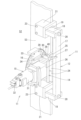
次に、本発明の実施の形態について図面を参照しながら説明する。まず、図1及び図2において、符号11は橋桁の縦リブ及び落橋防止ブロックの切断装置を示し、この切断装置11は、縦リブ53の長さ方向に沿って又は落橋防止ブロック55(図16参照)に沿って配設するガイド部12と、ガイド部12のガイドレール13(図1参照)に沿って移動可能で、かつ切断機15を保持するブロックジョイント14と、溶接部分を切断する切断刃16を備える切断機15とから構成される。
Next, an embodiment of the present invention will be described with reference to the drawings. First, in Figs. 1 and 2,
橋桁の縦リブ及び落橋防止ブロックの切断装置11は、高速道路51等の高架の橋桁52に垂直方向に沿って溶接された長板状の縦リブ53の溶接部分53aを切断するための、あるいは橋桁52のジョイント部分54近傍に溶接された落橋防止ブロック55の溶接部分55aを切断するための切断装置である(図8から図11、図16及び図17参照)。
The
ガイド部12は、図2から図4に示すように、角柱状に形成された所用長さの本体部17と、本体部17の内側に沿って設けられる長板状のガイドレール13(図1参照)と、本体部17の両端から折曲する折曲部18の基部19に設けられ、縦リブ53又は橋桁52を保持する保持手段(クランプ21又は磁石22)とを有する。
As shown in Figures 2 to 4, the
折曲部18は、本体部17とは別体で厚板状に形成され、本体部17と折曲部18とを取付ボルト20で一体的に固定する(図2から図4参照)。なお、取付ボルト20を用いずに、本体部17と折曲部18とを一体成形してもよい。
The
保持手段は、具体的には、縦リブ53を挟持するクランプ21(図1から図4参照)、又は橋桁52に磁着する磁石22(図17参照)である。
縦リブ53を切断するときは、クランプ21で縦リブ53を挟持して、クランプボルト23で強固に固定する(図1から図4参照)。また、落橋防止ブロック55を切断するときは磁石22を橋桁52に磁着させて強固に固定する(図17参照)。なお、図17及び図18中の符号22aは、磁力を作動又は解除するための磁石スイッチである。
Specifically, the holding means is a clamp 21 (see FIGS. 1 to 4) that clamps the
When cutting the
ブロックジョイント14は、図1及び図3に示すように、ガイドレール13を挟持して移動可能なブロック部24と、ガイドレール13に締め付けて固定可能なストッパー部25と、挿入された切断機15を保持する保持部26とを有する。
As shown in Figures 1 and 3, the block joint 14 has a
ブロック部24は、中央部分に図示しない溝状部を有しており、長板状のガイドレール13を挟持して長手方向に移動することができる仕組みになっている(図1参照)。
The
ストッパー部25は、レールストッパー27を操作することにより、ガイドレール13に締め付けて、ブロックジョイント14を固定状態に維持することができる。
このようにブロックジョイント14を固定状態に維持することによって、切断刃16の回転によって生じる反動力を抑止できる。つまり、縦リブ53や落橋防止ブロック55の切断時に切断刃16の回転方向又は回転方向と逆方向の反動力(図1の矢印A参照)を抑止できるので、切断刃16がブレたりズレたりしないで正確な切断位置を切断できるのである。
By operating the
By keeping the block joint 14 fixed in this way, it is possible to suppress the reaction force generated by the rotation of the
保持部26は、図1、図3及び図4に示すように、コ字状に形成されており、挿入される切断機15を囲繞して拘持する(図1及び図2参照)。
また、保持部26の両側には、板状の調整プレート28が設けられており、調整プレート28の端部に沿った位置には、凸条部30が設けられている(図2から図4参照)。
そして、調整プレート28は、長孔40にプレートボルト29が取り付けられており(図2から図4参照)、プレートボルト29の締緩操作で取付位置が調整可能であり、その結果、凸条部30を任意の位置に調整できる。
なお、凸条部30は、後述する切断ガイド33の係止レール34を係止する。
As shown in FIGS. 1, 3 and 4, the holding
Further, a plate-shaped
The
The protruding
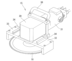
切断機15は、図5及び図6に示すように、切断刃16と、切断刃16を回転駆動させるモーター31と、モーター31の駆動をオンオフするスイッチ32と、切断刃16をコ字状に覆う切断ガイド33とを有する。
なお、図中の符号38は把手を示し、符号39は減速ギヤボックスを示す。
As shown in Figures 5 and 6, the
In the figure,
切断刃16は、円盤状に形成され、具体的木にはウェルディングソーである。従って、硬質な鋼材などを切断できるので、縦リブ53や落橋防止ブロック55の溶接部分53a、55aを切断することが可能である。
The
切断ガイド33の両側には、図5及び図6に示すように、L字状の係止レール34が所要長さに渡って設けられている。係止レール34は、切断機15を保持部26に挿入する状態において、調整プレート28の凸条部30を係止する部位である。
As shown in Figures 5 and 6, an L-shaped
調整プレート28の凸条部30と、切断ガイド33の係止レール34との関係について説明する。
調整プレート28は、プレートボルト29の締緩操作により取付位置調整することで、凸条部30の位置調整ができる。つまり、切断機15を保持部26に挿入するときに、切断ガイド33と一連の切断刃16による切断位置が最適位置になるよう凸条部30の位置調整ができるのである。
従って、凸条部30を係止レール34に係止することによって、切断ガイド33と一連の切断刃16が最適で任意な切断位置を切削できて、切断刃の浮き上がり現象も防止でき、その結果、橋桁を傷つけることがない。
The relationship between the
The position of the
Therefore, by engaging the
次に、切断装置11を使用して、図8及び図9に示す、高速道路51の橋桁52に垂直方向に沿って溶接された長板状の縦リブ53の溶接部分53a(図1参照)を切断する手順について説明する。
まず、ガイド部12のクランプ21で縦リブ53を挟持して、クランプボルト23で固定してから、ブロックジョイント14のブロック部24でガイドレール13を挟持し、レールストッパー27を操作してストッパー部25をガイドレール13に固定する。このときブロックジョイント14は固定状態に維持される。
そして、保持部26に対して調整プレート28の取付位置を調整してプレートボルト29で固定する。このとき、切断刃16による切断位置が適正位置になるよう凸条部30の位置調整がなされる。
次に、切断機15を保持部26に挿入すると共に、調整プレート28の凸条部30に切断ガイド33の係止レール34を係止させる。
さらに、切断機15のスイッチ32をオンにしてモーター31を駆動させて、切断刃16を縦リブ53の溶接部分に押し当てて切削する。
Next, a procedure for using the
First, the
Then, the mounting position of the
Next, the cutting
Furthermore, the
このようにして当該切断位置の切削が終了したら、レールストッパー27を操作してストッパー部25のガイドレール13への固定状態を解除し、ブロックジョイント14を縦リブ53の長さ方向に沿って下方向(又は上方向)に約5~20cm程度移動する。
そして、レールストッパー27を操作してストッパー部25をガイドレール13に再び固定してから、前記の場合と同様な手順を経て、切断刃16を縦リブ53の溶接部分に押し当てて切削する。
Once cutting of the cutting position has been completed in this manner, the
Then, the
このような手順を複数回繰り返して、ガイド部12の長さ方向に沿って切断が終了したら、クランプボルト23を緩めて、クランプ21での縦リブ53への固定状態を解除してから、ガイド部12を縦リブ53の長さ方向に沿って下方向(又は上方向)に、次の切削区間へ移動する。
そして、次の切削区間でのガイド部12のセッティングを行い、レールストッパー27を操作してストッパー部25をガイドレール13に再び固定してから、前記の場合と同様な手順を経て、切断刃16を縦リブ53の溶接部分に押し当てての切削を複数回繰り返して切削を行う。
This procedure is repeated several times, and when cutting along the length of the
Then, the
このようにして、縦リブ53を切削した後には、図10及び図11に示すように、縦リブ53上端部35及び下端部36に未切削部分が残る。
この未切削部分を切削する場合は、図12から図15に示す、クランプ付きガイド部材37を使用して切削を行う。
After the
When cutting this uncut portion, a clamp-equipped
クランプ付きガイド部材37は、図12から図15に示すように、挿入される切断機15を保持するコ字状の本体部41と、本体部41の一端との間に縦リブ53を挟持するクランプ板42と、クランプ板42に設けられるクランプボルト43と、本体部41の両側に設けられる板状の調整プレート44とを有し、調整プレート44の端部には、凸条部45が設けられている。そして、調整プレート44は、長孔46にプレートボルト47が取り付けられており、プレートボルト47の締緩操作で取付位置が調整可能であり、その結果、凸条部45を任意の位置に調整できる。
凸条部45は、切断ガイド33の係止レール34を係止する部位である。
12 to 15, the clamp-equipped
The protruding
このような構成のクランプ付きガイド部材37を縦リブ53の上端部35(又は下端部36)にセッティングして、調整プレート44の取付位置の調整を行い、本体部41に切断機15を挿入すると共に、調整プレート44の凸条部45に切断ガイド33の係止レール34を係止させる。
さらに、切断機15のスイッチ32をオンにしてモーター31を駆動させて、切断刃16を縦リブ53の溶接部分に押し当てて、縦リブ53上端部35及び下端部36に残る未切削部分を切削する。
さらに、未切削部分が残存する場合は、残存部分をセーバーソーやチップソーで撤去する。
The clamped
Furthermore, the
Furthermore, if any uncut portions remain, they are removed using a saber saw or a tipped saw.
以上のような手順で縦リブ53の全長を切断することにより、縦リブ53の溶接部分を正確に切断できて、橋桁52を傷つけることがない。また、火花が出ないので安全に作業が行える。
By cutting the entire length of the
次に、切断装置11を使用して、図16に示す、高速道路51の橋桁52のジョイント部分54近傍に溶接された落橋防止ブロック55の溶接部分を切断する手順について説明する。
まず、図17に示すように、ガイド部12の磁石22を磁石スイッチ22aのオンオフ操作で橋桁52に磁着して固定してから、ブロックジョイント14のブロック部24でガイドレール13を挟持するなどの、前記の縦リブ53を切断時と同様な手順を経て、切断刃16を落橋防止ブロック55の溶接部分に押し当てて切削する。
Next, a procedure for using the
First, as shown in Figure 17, the
なお、落橋防止ブロック55の近傍に横リブ57が存在する場合には、図18に示すように、磁石22に代えて、クランプ21で横リブ57を挟持して、クランプボルト23で固定してから、前記の場合と同様な手順を経て切削を行うことができる。
If a
以上のような手順で落橋防止ブロック55の溶接部分を切断することにより、落橋防止ブロック55の任意の切断位置を正確に切断できて、橋桁を傷つけることがない。また、火花が出ないので安全に作業が行える。
By cutting the welded parts of the bridge
また、本発明の橋桁の縦リブ及び落橋防止ブロックの切断装置11は、縦リブ53及び落橋防止ブロック55だけでなく、横リブ57に応用して切断することが可能である。
The cutting
11 橋桁の縦リブ及び落橋防止ブロックの切断装置
12 ガイド部
13 ガイドレール
14 ブロックジョイント
15 切断機
16 切断刃
17 本体部
18 折曲部
19 基部
20 取付ボルト
21 クランプ
22 磁石
22a 磁石スイッチ
23 クランプボルト
24 ブロック部
25 ストッパー部
26 保持部
27 レールストッパー
28 調整プレート
29 プレートボルト
30 凸条部
31 モーター
32 スイッチ
33 切断ガイド
34 係止レール
35 上端部
36 下端部
37 クランプ付きガイド部材
38 把手
39 減速ギヤボックス
40 長孔
41 本体部
42 クランプ板
43 クランプボルト
44 調整プレート
45 凸条部
46 長孔
47 プレートボルト
51 高速道路
52 橋桁
53 縦リブ(垂直補鋼材)
53a 溶接部分
54 ジョイント部分
55 落橋防止ブロック
55a 溶接部分
56 ワイヤー
57 横リブ
58 アスファルト舗装
REFERENCE SIGNS
53a Welded
Claims (4)
該切断装置は、前記縦リブの長さ方向に沿って配設するガイド部と、該ガイド部のガイドレールに沿って移動可能で、かつ切断機を保持するブロックジョイントと、前記溶接部分を切断する切断刃を備える前記切断機とから構成されており、
前記ガイド部は、所用長さの本体部と、該本体部に設けられる長板状の前記ガイドレールと、前記本体部の両端から折曲する折曲部の基部に設けられ前記縦リブを保持する保持手段とを有し、
前記ブロックジョイントは、前記ガイドレールを挟持して移動可能なブロック部と、前記ガイドレールに締め付けて固定可能なストッパー部と、挿入された前記切断機を保持する保持部とを有し、
前記切断機は、前記切断刃と、該切断刃を回転駆動させるモーターと、該モーターの駆動をオンオフするスイッチと、前記切断刃をコ字状に覆う切断ガイドとを有し、
前記保持部の両側には、プレートボルトの締緩で取付位置が調整可能な調整プレートが設けられており、該調整プレートの端部には、凸条部を有し、
前記切断ガイドには、前記凸条部に係止する係止レールが設けられており、
前記切断機を前記保持部に挿入する状態で、前記凸条部に前記係止レールを係止させて、前記切断刃による切断位置のズレを防止する構成であること
を特徴とする橋桁の縦リブの切断装置。 A cutting device for cutting a welded portion of a long plate-shaped longitudinal rib welded along a vertical direction to an elevated bridge girder,
The cutting device is composed of a guide section disposed along the longitudinal direction of the vertical rib, a block joint movable along the guide rail of the guide section and holding a cutting machine, and the cutting machine having a cutting blade for cutting the welded portion,
The guide portion has a main body portion of a required length, the guide rail having a long plate shape provided on the main body portion, and a holding means provided at a base of a bent portion that is bent from both ends of the main body portion and holds the vertical rib ,
the block joint has a block portion that can move while clamping the guide rail, a stopper portion that can be fastened to the guide rail and fixed thereto, and a holding portion that holds the inserted cutting machine,
The cutter includes the cutting blade, a motor for rotating the cutting blade, a switch for turning on and off the motor, and a cutting guide for covering the cutting blade in a U-shape,
An adjustment plate is provided on both sides of the holding portion, and the mounting position of the adjustment plate can be adjusted by tightening or loosening the plate bolt. The end of the adjustment plate has a protruding portion.
The cutting guide is provided with a locking rail that locks onto the protruding portion,
The locking rail is locked to the protruding portion when the cutting tool is inserted into the holding portion, thereby preventing the cutting position of the cutting blade from shifting.
A cutting device for longitudinal ribs of a bridge girder, comprising:
を特徴とする請求項1に記載の橋桁の縦リブの切断装置。 The cutting device for longitudinal ribs of a bridge girder according to claim 1, wherein the holding means is a clamp or a magnet .
を特徴とする請求項1に記載の橋桁の縦リブの切断装置。 The device for cutting longitudinal ribs of bridge girders according to claim 1, characterized in that the stopper portion is fastened to the guide rail to maintain a fixed state, thereby suppressing a reaction force generated by rotation of the cutting blade.
を特徴とする請求項1に記載の橋桁の縦リブの切断装置。 The device for cutting longitudinal ribs of a bridge girder according to claim 1, characterized in that the cutting blade is a welding saw.
Priority Applications (1)
| Application Number | Priority Date | Filing Date | Title |
|---|---|---|---|
| JP2021098561A JP7670552B2 (en) | 2021-06-14 | 2021-06-14 | Cutting device for longitudinal ribs of bridge girders |
Applications Claiming Priority (1)
| Application Number | Priority Date | Filing Date | Title |
|---|---|---|---|
| JP2021098561A JP7670552B2 (en) | 2021-06-14 | 2021-06-14 | Cutting device for longitudinal ribs of bridge girders |
Publications (2)
| Publication Number | Publication Date |
|---|---|
| JP2022190297A JP2022190297A (en) | 2022-12-26 |
| JP7670552B2 true JP7670552B2 (en) | 2025-04-30 |
Family
ID=84601923
Family Applications (1)
| Application Number | Title | Priority Date | Filing Date |
|---|---|---|---|
| JP2021098561A Active JP7670552B2 (en) | 2021-06-14 | 2021-06-14 | Cutting device for longitudinal ribs of bridge girders |
Country Status (1)
| Country | Link |
|---|---|
| JP (1) | JP7670552B2 (en) |
Citations (7)
| Publication number | Priority date | Publication date | Assignee | Title |
|---|---|---|---|---|
| JP2007196322A (en) | 2006-01-26 | 2007-08-09 | Shiyuuzo Hiwaki | Cutter |
| JP2013060761A (en) | 2011-09-14 | 2013-04-04 | Toshiba Corp | Anchor bolt cutting tool |
| JP2015121072A (en) | 2013-12-25 | 2015-07-02 | 株式会社ニチワ | Base plate cutting device |
| JP2017197916A (en) | 2016-04-25 | 2017-11-02 | ライト工業株式会社 | Repair method and repair structure for bridge falling prevention device |
| JP2018178555A (en) | 2017-04-14 | 2018-11-15 | 川田工業株式会社 | Method of repairing and reinforcing vertical joints in steel structure, and reinforcing material for vertical joints |
| JP2021004501A (en) | 2019-06-26 | 2021-01-14 | 中国電力株式会社 | Rake for dust remover, and dust remover |
| US20210308779A1 (en) | 2018-08-13 | 2021-10-07 | Utv Center Ab | Weld cutting machine and method for cutting welds |
-
2021
- 2021-06-14 JP JP2021098561A patent/JP7670552B2/en active Active
Patent Citations (7)
| Publication number | Priority date | Publication date | Assignee | Title |
|---|---|---|---|---|
| JP2007196322A (en) | 2006-01-26 | 2007-08-09 | Shiyuuzo Hiwaki | Cutter |
| JP2013060761A (en) | 2011-09-14 | 2013-04-04 | Toshiba Corp | Anchor bolt cutting tool |
| JP2015121072A (en) | 2013-12-25 | 2015-07-02 | 株式会社ニチワ | Base plate cutting device |
| JP2017197916A (en) | 2016-04-25 | 2017-11-02 | ライト工業株式会社 | Repair method and repair structure for bridge falling prevention device |
| JP2018178555A (en) | 2017-04-14 | 2018-11-15 | 川田工業株式会社 | Method of repairing and reinforcing vertical joints in steel structure, and reinforcing material for vertical joints |
| US20210308779A1 (en) | 2018-08-13 | 2021-10-07 | Utv Center Ab | Weld cutting machine and method for cutting welds |
| JP2021004501A (en) | 2019-06-26 | 2021-01-14 | 中国電力株式会社 | Rake for dust remover, and dust remover |
Also Published As
| Publication number | Publication date |
|---|---|
| JP2022190297A (en) | 2022-12-26 |
Similar Documents
| Publication | Publication Date | Title |
|---|---|---|
| US6899004B1 (en) | Sawing apparatus and saw fence system | |
| JP6715678B2 (en) | Cutting device and floor slab cutting method | |
| JP2011196172A (en) | Cutting method, and cutting tool guide jig and ruler used for the same | |
| JP7670552B2 (en) | Cutting device for longitudinal ribs of bridge girders | |
| US7257896B2 (en) | Tool for breaking spot welds | |
| JPH0643685B2 (en) | Horizontal cutting method of bridge deck | |
| JP2020012275A (en) | Removal method of floor slab and rail fixing device | |
| JP6456328B2 (en) | Grating lid fixing device | |
| JPH0643682B2 (en) | Bridge floor slab removal method | |
| JP5266538B2 (en) | Refurbishment method of free slope gutter | |
| JP2015121072A (en) | Base plate cutting device | |
| JPH0643684B2 (en) | Horizontal cutting method of bridge deck | |
| CN112847844B (en) | concrete cutter | |
| JP3968380B1 (en) | Removal method of expansion joint | |
| JP5222345B2 (en) | How to repair drainage | |
| JP6628452B2 (en) | Concrete slab cutting machine and concrete slab cutting method | |
| JP5723251B2 (en) | Anti-theft device for grating | |
| JP2019084634A (en) | Rib cutting device for steel deck plate for floor formwork | |
| JP4030378B2 (en) | How to cut and remove bridge joints | |
| JP4747080B2 (en) | Grating fixing device | |
| KR20100010216A (en) | A signs supporting appratus | |
| FR2639389A1 (en) | Construction joint profile | |
| JP2003268865A (en) | Grating | |
| JP2026046609A (en) | Stud dowel cutting machine | |
| JP4782148B2 (en) | Groove cover |
Legal Events
| Date | Code | Title | Description |
|---|---|---|---|
| A621 | Written request for application examination |
Free format text: JAPANESE INTERMEDIATE CODE: A621 Effective date: 20240408 |
|
| A521 | Request for written amendment filed |
Free format text: JAPANESE INTERMEDIATE CODE: A523 Effective date: 20240409 |
|
| A977 | Report on retrieval |
Free format text: JAPANESE INTERMEDIATE CODE: A971007 Effective date: 20241129 |
|
| A131 | Notification of reasons for refusal |
Free format text: JAPANESE INTERMEDIATE CODE: A131 Effective date: 20241203 |
|
| A521 | Request for written amendment filed |
Free format text: JAPANESE INTERMEDIATE CODE: A523 Effective date: 20250120 |
|
| TRDD | Decision of grant or rejection written | ||
| A01 | Written decision to grant a patent or to grant a registration (utility model) |
Free format text: JAPANESE INTERMEDIATE CODE: A01 Effective date: 20250325 |
|
| A61 | First payment of annual fees (during grant procedure) |
Free format text: JAPANESE INTERMEDIATE CODE: A61 Effective date: 20250417 |
|
| R150 | Certificate of patent or registration of utility model |
Ref document number: 7670552 Country of ref document: JP Free format text: JAPANESE INTERMEDIATE CODE: R150 |