JP7668552B2 - System and Program - Google Patents
System and Program Download PDFInfo
- Publication number
- JP7668552B2 JP7668552B2 JP2023028071A JP2023028071A JP7668552B2 JP 7668552 B2 JP7668552 B2 JP 7668552B2 JP 2023028071 A JP2023028071 A JP 2023028071A JP 2023028071 A JP2023028071 A JP 2023028071A JP 7668552 B2 JP7668552 B2 JP 7668552B2
- Authority
- JP
- Japan
- Prior art keywords
- color
- light
- alarm
- warning
- radio
- Prior art date
- Legal status (The legal status is an assumption and is not a legal conclusion. Google has not performed a legal analysis and makes no representation as to the accuracy of the status listed.)
- Active
Links
Images


Landscapes
- Navigation (AREA)
- Instrument Panels (AREA)
- Traffic Control Systems (AREA)
- Emergency Alarm Devices (AREA)
- Instructional Devices (AREA)
- Alarm Systems (AREA)
- Audible And Visible Signals (AREA)
Description
本発明は、警報条件を満たした場合に報知するシステム及びプログラムに関するものである。 The present invention relates to a system and program that issues an alert when an alarm condition is met.
近年、自動車の速度を測定する速度測定装置が路上周辺等に多数設置されるようになっている。速度測定装置の一例を示すと、所定周波数帯域のマイクロ波を車両に向けて発射し、その反射波を受信して車両の走行スピードを測定するようになっている。 In recent years, speed measuring devices that measure the speed of automobiles have been installed in large numbers around the roads. One example of a speed measuring device emits microwaves in a specific frequency band toward a vehicle, receives the reflected waves, and measures the vehicle's traveling speed.
一方、係る速度測定装置の存在を検出するため、その速度測定装置から発射されたマイクロ波を検出して警報を出力するように構成されたマイクロ波検出器が従来から知られている。しかし、速度測定装置の設置位置や、道路の状態その他の周囲環境により、従来のマイクロ波検出器は、比較的遠くから検出可能なものと、比較的近づいてからでないと検出しにくいものがある。 Meanwhile, microwave detectors that are configured to detect the presence of such speed measuring devices and output an alarm by detecting microwaves emitted from the speed measuring devices have been conventionally known. However, depending on the installation location of the speed measuring device, road conditions, and other surrounding environments, conventional microwave detectors can detect the speed measuring device from a relatively long distance, while others are difficult to detect unless the device is relatively close.
また、速度測定装置の中には、従来のマイクロ波検出器では検出できないものもある。
一例を挙げると、ループ式と称されるように、地中にループ状のコイルを埋め込み、そのコイルの上を車両が通過するのを検知するとともに車速も判定するものがある。また、マイクロ波以外の光を用いて車両の速度を検出するものもある。
Additionally, some speed measuring devices cannot be detected by conventional microwave detectors.
For example, there is a type called a loop type, which buries a loop-shaped coil in the ground and detects when a vehicle passes over the coil and determines the vehicle speed. There are also types that use light other than microwaves to detect the vehicle speed.
そこで、最近では、予め速度測定装置の設置位置情報を記憶させておき、GPS(Global
Positioning System )情報を利用して現在位置が記憶した設置位置に近づいた場合(所定の関係になった場合)に、マイクロ波の検知の有無に関係なく警告を発するようにした車載用電子機器がある(特許文献1)。
Recently, the location information of the speed measuring device is stored in advance and used for GPS (Global Positioning System).
There is an in-vehicle electronic device that uses information from the Automotive Positioning System (ADAS) to issue a warning when the current position approaches a stored installation position (when a specified relationship is reached), regardless of whether microwaves are detected or not (Patent Document 1).
たとえば、現在位置が、速度測定装置の設置位置から1000m以内に入った位置になった場合に第一の警告を行い、さらに速度測定装置の設置位置から500m以内に入った位置になった場合に、第二の警告を行うなどしている。 For example, if the current position is within 1000 m of the location of the speed measuring device, a first warning is issued, and if the current position is within 500 m of the location of the speed measuring device, a second warning is issued.
具体的な報知の態様としては、例えば、「左方向 1km先 高速道 Hシステムです」、「すぐ先 一般道 Nシステムです」などの相対位置関係や、目的の内容を特定する内容を音声情報としてスピーカから出力したり、それらの警報対象を直接的に表す文字やイメージを表示部に表示したりすることが行われる。警報対象を直接的に表すイメージは、速度測定装置等の警報対象を撮像した実写真や、それを模した画像などがある。 Specific notification modes include, for example, outputting from a speaker audio information specifying the relative position relationship, such as "Turn left, 1 km ahead, H system on the expressway," or "Just ahead, N system on the general road," or displaying on the display unit characters or an image that directly represents the target of the warning. Images that directly represent the target of the warning include an actual photograph of the target of the warning, such as a speed measuring device, or an image that mimics it.
さらに、表示部の画面サイズが大きくなるとともにカラー画面になることから、表示部を用いて出力する情報の種類と量も増えている。出力する情報の一例としては、自車位置周辺の地図があり、係る地図上に自車位置を示すマークと、警報対象を示すマーク(2D,3D)を重ねて表示することで、具体的な位置関係が認識できる。さらに、報知している警報対象の種類によって背景色を変え、警報対象との距離が基準値よりも近くなると背景色を赤色に変更することも行われる。 Furthermore, as the screen size of the display unit increases and the screen becomes color, the types and amount of information output using the display unit are also increasing. One example of the information output is a map of the area around the vehicle's position, and by displaying a mark indicating the vehicle's position and a mark (2D, 3D) indicating the target of the warning superimposed on the map, the specific positional relationship can be recognized. Furthermore, the background color changes depending on the type of target of the warning, and the background color is changed to red when the distance to the target of the warning becomes closer than a reference value.
従来の装置は、表示部の画面サイズが大きくなるに伴い表示部を用いて提供する情報量も増加したが、運転中のドライバーは前方その他車両の周囲を見る必要から、係る表示部を注視することは難しく、提供された情報の内容を瞬時に理解するのが難しいことがある。例えば、表示部に多数の情報を一度に出力されると、ユーザは表示された全ての情報を見ることができず、重要な情報を見落とすおそれがある。また、表示部に地図を表示している場合、現在位置と警報対象との距離が基準距離以下になり背景色を赤色などに変えると、地図が見にくくなる。特に、地図の場合、道路等を色分け表示しており、道路の色と変更した背景色が同色系となると、より見にくくなるといった各種の問題がある。 In conventional devices, as the screen size of the display unit increases, the amount of information provided by the display unit also increases. However, because a driver needs to look ahead and around the vehicle while driving, it is difficult for the driver to focus on the display unit, and it can be difficult to instantly understand the content of the information provided. For example, if a large amount of information is output to the display unit at once, the user cannot see all the displayed information and may miss important information. In addition, when a map is displayed on the display unit, if the distance between the current position and the alarm target falls below the reference distance and the background color is changed to red, for example, the map becomes difficult to see. In particular, in the case of a map, roads and the like are displayed in different colors, and if the color of the road and the changed background color are the same color system, various problems arise, such as the map becoming even more difficult to see.
上述した問題を解決するために、本発明に係るシステムは、(0)表示画面に情報の表示をさせる機能と、警報条件を満たした場合に、発光部の発光状態を制御して警報報知をさせる機能とを備えたシステムであって、前記発光状態の制御として、前記警報条件を満たした警報対象に対応した発光色で発光させる機能と、前記警報条件を満たした場合に、前記表示画面に前記発光部の発光色と同系色の表示をさせる機能を備え、前記発光部はロゴが前記発光色で発光する構成とした。 表示画面に情報の表示をさせる機能と、警報条件を満たした場合に、発光部の発光状態を制御して警報報知をさせる機能とを備えたシステムであって、前記発光状態の制御として、前記警報条件を満たした警報対象に対応した発光色で発光させる機能と、前記警報条件を満たした場合に、前記表示画面に前記発光部の発光色と同系色の表示をさせる機能を備え、前記発光部はロゴを含む周辺領域が前記発光色で発光する構成とした。
(1)警報条件を満たした場合に、LEDを光源とする発光部の発光状態を制御して警報報知をする制御手段を備えたシステムであって、前記発光状態の制御は、前記警報条件を満たした警報対象に対応した発光色で発光するようにした。
In order to solve the above-mentioned problems, the system according to the present invention is (0) a system having a function of displaying information on a display screen, and a function of controlling the light-emitting state of a light-emitting unit to issue an alarm when an alarm condition is satisfied, the system having a function of controlling the light-emitting state to emit light in a light-emitting color corresponding to an alarm target that satisfies the alarm condition, and a function of displaying a color similar to the light-emitting color of the light-emitting unit on the display screen when the alarm condition is satisfied, and the light-emitting unit is configured to emit a logo in the light-emitting color.A system having a function of displaying information on a display screen, and a function of controlling the light-emitting state of a light-emitting unit to issue an alarm when an alarm condition is satisfied, the system having ... to emit light in a light-emitting color corresponding to an alarm target that satisfies the alarm condition, and a function of displaying a color similar to the light-emitting color of the light-emitting unit on the display screen when the alarm condition is satisfied, and the light-emitting unit is configured to emit light in the light-emitting color around a surrounding area including a logo.
(1) A system equipped with a control means for controlling the light-emitting state of an LED-based light-emitting unit to issue an alarm when an alarm condition is met, the light-emitting state being controlled so as to emit light in a color corresponding to the object of the alarm that has met the alarm condition.
LEDを備えた発光部は、発光部の光源がLEDであることを言う。LEDが露出している場合、LED自体が発光部となり、装置のケース本体(筐体)内にLEDが内蔵されている場合にはケース本体の外部から発光しているのがわかる領域が発光部となる。後者の場合、例えばケース本体の表面の所定の領域が発光部となる。係る所定の領域は、例えばLEDからの光が透過するようにケース本体の壁面を肉薄にしたり、ケース本体の壁面に窓孔を開けるとともに係る窓孔に半透明等の光が透過する部材からなるカバーを装着したりして構成するとよい。 A light-emitting unit equipped with an LED means that the light source of the light-emitting unit is an LED. When the LED is exposed, the LED itself becomes the light-emitting unit, and when the LED is built into the case body (housing) of the device, the area where it is visible that the LED is emitting light from outside the case body becomes the light-emitting unit. In the latter case, for example, a specified area on the surface of the case body becomes the light-emitting unit. This specified area may be configured, for example, by making the wall of the case body thin so that light from the LED can pass through, or by opening a window hole in the wall of the case body and attaching a cover made of a light-transmitting material such as translucency to the window hole.
発光部は、警報条件を満たした警報対象に対応した発光色で発光する。例えば、警報対象と発光色情報を関係づけた関係情報を所定の記憶手段に記憶保持しておく。発光色情報は、発光色が何であるかを特定する情報である。制御手段は、警報条件を満たした場合、記憶手段にアクセスして記憶保持していた関係情報から当該警報条件を満たした警報対象
に対応する発光色情報を取得し、その発光色情報で特定される発光色になるようにLEDの発光を制御する。警報条件は、例えば警報対象と現在位置の位置関係が所定の接近関係にあるなど位置情報に基づくものや、所定の電波・無線信号の受信,車両の状態・運転状態など位置情報に基づかないものがある。位置情報に基づかないものとしては、上記例示列挙したように、所定の電波の受信のように車両の外部からの情報に基づくものと、急発進・急ハンドル(加速度センサのセンサ値が基準値以上)のような危険運転など、燃費の悪い走行など、車両内(車両自体・ドライバー)の情報に基づくものなどがある。
The light emitting unit emits light in a color corresponding to the object of warning that satisfies the warning condition. For example, relational information relating the object of warning and the light emitting color information is stored and held in a predetermined storage means. The light emitting color information is information that specifies what the light emitting color is. When the warning condition is satisfied, the control means accesses the storage means, acquires the light emitting color information corresponding to the object of warning that satisfies the warning condition from the relational information stored and held, and controls the light emission of the LED so that the light emitting color is the color specified by the light emitting color information. The warning condition may be based on position information, such as a positional relationship between the object of warning and the current position being in a predetermined proximity relationship, or may be not based on position information, such as reception of a predetermined radio wave or wireless signal, or the state or driving state of the vehicle. As examples of conditions that are not based on position information, there are conditions that are based on information from outside the vehicle, such as reception of a predetermined radio wave, and conditions that are based on information inside the vehicle (the vehicle itself or the driver), such as dangerous driving such as sudden starting or sudden steering (the sensor value of the acceleration sensor is equal to or greater than a reference value), or poor fuel consumption driving.
警報対象に対応する発光色であるが、位置情報に基づく警報対象の場合、例えば、位置情報が登録されている警報対象ごとに発光色を設定(関連付け)してもよいし、警報対象の種類毎に発光色を設定してもよい。また、警報対象の種類毎とした場合、実施形態で一部例示したように、固定設置される速度測定装置(レーダー)、Nシステム、交通監視ポイント、検問エリア、道の駅など細かい種類別に設定しても良いし、重要度(危険度)に応じて複数のグループに分けるとともにグループ毎に発光色を設定し、同一グループに属する警報対象は同じ発光色としても良い。重要度に基づく発光色の対応付けは、例えば、速度測定装置などの重要度の高いものは赤色、Nシステムなどの重要度が中(注意を与える)のものは青色、道の駅などの需要度が低い(情報提供程度)ものは緑色などとするとよい。 The light color corresponds to the target of the warning. In the case of a target of warning based on location information, for example, a light color may be set (associated) for each target of warning whose location information is registered, or a light color may be set for each type of target of warning. In addition, when a light color is set for each type of target of warning, as illustrated in the embodiment, a light color may be set for each detailed type such as a fixed speed measuring device (radar), N system, traffic monitoring point, checkpoint area, roadside station, etc., or a light color may be set for each group according to importance (danger level), and the same light color may be set for targets of warning belonging to the same group. For example, light colors may be associated based on importance such as red for high importance such as a speed measuring device, blue for medium importance (warning) such as N system, and green for low demand (information provision level) such as roadside stations.
ドライバーは、運転中、前方その他の車両の周囲を注意する必要がある。本発明では、警報条件を満たした場合に、警報対象に対応する発光色で発光部が発光するので、ドライバーは仮に本システムの装置(発光部)が視界に入っていなくても、発光したことはわかり、少し視線をずらすだけで視界内に発光部をとらえ、その発光色を確認できる。これにより、警報条件を満たした警報対象が周囲に存在していること、並びにその警報対象が何であるか等について知ることができる。多数の警報情報が報知されるのではなく、また、所定の発光色で発光というシンプルな警報であるため、ドライバーは発光部を長時間注視することなくその警報内容を理解できるので、車両の内外の運転に必要な情報収集に注力できる。 While driving, drivers need to pay attention to the area ahead and other areas around the vehicle. In this invention, when the warning conditions are met, the light-emitting unit emits light in a color that corresponds to the object of the warning. Therefore, even if the device (light-emitting unit) of this system is not in the driver's field of vision, the driver knows that the light has been emitted, and can catch the light-emitting unit in the driver's field of vision and confirm the color of the light by simply shifting his or her gaze slightly. This allows the driver to know that there is an object of warning that meets the warning conditions in the surroundings, as well as what the object of warning is. Since a large amount of warning information is not notified and the warning is a simple one that emits light in a specified color, the driver can understand the warning content without staring at the light-emitting unit for a long time, and can focus on collecting information necessary for driving inside and outside the vehicle.
(2)前記LEDはカラーLEDであり、前記制御手段は、警報レベルにより段階的に前記発光色を変えるとよい。カラーLEDを用いることで、1つのLEDでもって多種類の色を表現することができる。例えば、RGBの3原色LEDを使用し、PWMを使用した色強度制御で、Rが5ビット、Gが5ビット、Bが5ビットの合計で15bitとすると、32,768色の色制御が実現でき、Rが8ビット、Gが8ビット、Bが8ビットの合計24ビットの合計24ビットとすれば、16,777,216色の色制御が可能となる。よって、警報レベルが低い場合から高い場合まで、スムーズに階調制御を行うことで発光色が徐々に変化するような警報をすることができる。従来の表示画面上に警報レベルについての情報を報知する場合、例えば受信した電波の信号レベルを報知するには、警報レベルを例えば5段階に分け、レベルが1つ上がる毎に発光している領域を1つ分増やす(延ばす)といったレベルメータのような態様をとっていたが、警報レベルに応じて発光色を徐々に変える制御を行うことで、警報レベルをアナログ的に表現することができ、高級感が増す。発光色は、たとえば、警報レベルが上がるほど青色系から赤色系に変更していくようにすると良い。 (2) The LED may be a color LED, and the control means may change the emitted color in stages depending on the alarm level. By using a color LED, a variety of colors can be expressed with one LED. For example, if an RGB three-color LED is used, and R is 5 bits, G is 5 bits, and B is 5 bits, totaling 15 bits, with color intensity control using PWM, color control of 32,768 colors can be realized, and if R is 8 bits, G is 8 bits, and B is 8 bits, totaling 24 bits, color control of 16,777,216 colors is possible. Therefore, it is possible to issue an alarm in which the emitted color changes gradually by smoothly performing gradation control from low to high alarm levels. Conventionally, when displaying information about an alarm level on a display screen, for example to display the signal level of a received radio wave, the alarm level is divided into, for example, five stages, and the illuminated area is increased (extended) by one for each level increase, like a level meter. However, by controlling the color of the emitted light to gradually change according to the alarm level, the alarm level can be expressed in an analog manner, which gives a more luxurious feel. For example, it is advisable to change the color of the emitted light from blue to red as the alarm level increases.
(3)前記制御手段は、警報レベルにより前記LEDの発光強度を変化させるようにするとよい。発光強度の変更は例えば発光色の明度や輝度を変えることで実現する。係る変更は、例えば輝度用PWMを用いることで輝度を変えることができるし、その他の公知の方法(LEDメーカ指定の方法)でLEDの色と明るさは設定できる。また、LEDの印加電圧を調整し発光量自体を変えても良い。(2)の発明のように発光色を変えるのではなく、発光強度を変えることでも、上記と同様の効果が期待できる。また、発光色の変更と発光強度の変更をあわせて行うようにしても良い。発光強度は、たとえば、警報レベルが上がるほど、暗い色から明るい色に変更或いは発光量を強く(大きく)していくようにすると良い。 (3) The control means may change the light emission intensity of the LED depending on the alarm level. The change in light emission intensity may be achieved, for example, by changing the brightness or luminance of the emitted color. Such a change may be achieved, for example, by using a luminance PWM to change the luminance, or the color and brightness of the LED may be set by other known methods (methods specified by the LED manufacturer). The amount of light emitted may also be changed by adjusting the voltage applied to the LED. The same effect as described above can be expected by changing the light emission intensity, rather than changing the light emission color as in the invention of (2). The light emission color and the light emission intensity may also be changed at the same time. For example, the light emission intensity may be changed from a dark color to a bright color or the light emission amount may be increased as the alarm level increases.
(4)前記警報条件は、電波の受信であり、前記警報レベルは、受信した前記電波の信号レベルとするとよい。例えば、速度測定装置から出射されるマイクロ波などの警報対象となる所定周波数の電波を受信した場合、受信した電波の信号レベルに対応して発光色や発光の強度を変更することで、無機質なデジタルレーダーレベルメータではなく受信した信号レベルをアナログ的に表現できるのでよい。 (4) The warning condition is reception of radio waves, and the warning level may be the signal level of the received radio waves. For example, when radio waves of a specific frequency that is the subject of a warning, such as microwaves emitted from a speed measuring device, are received, the color and intensity of the emitted light may be changed according to the signal level of the received radio waves, so that the received signal level can be expressed in an analog manner, rather than in an inorganic digital radar level meter.
(5)前記警報条件は、現在位置と警報対象が接近関係にあることであり、前記警報レベルは、前記接近関係の程度としてもよい。接近関係の程度は、例えば、距離が近づくほど警報レベルが高くなる制御をする。このようにすると、警報対象までのおおよその残り距離を理解できるので好ましい。 (5) The warning condition is that the current location and the object to be warned are in close proximity, and the warning level may be the degree of the closeness. The degree of closeness is controlled, for example, so that the warning level becomes higher as the distance becomes closer. This is preferable because it allows the user to understand the approximate remaining distance to the object to be warned.
警報レベルは、上述した(4)の電波の受信や(5)の接近関係以外にも、例えば、危険運転の程度(加速度センサのセンサ値が大きいほど危険運転の程度が高い)や、燃費(単位時間当たりの燃料消費量が多い,急加速をするなど)など各種のものがある。 In addition to the above-mentioned (4) radio wave reception and (5) proximity, there are various other warning levels, such as the degree of dangerous driving (the higher the sensor value of the acceleration sensor, the more dangerous the driving) and fuel economy (high fuel consumption per unit time, sudden acceleration, etc.).
(6)前記警報レベルに対応して前記発光色の周波数を段階的に変えることで、前記発光色を変えるようにするとよい。周波数の変更をすることで発光色を連続的に変更できる。この場合に周波数の低い方を警報レベルが1、周波数の高い方を警報レベルが最大としてスムーズな階調制御をすると良い。 (6) The emitted color may be changed by gradually changing the frequency of the emitted color in response to the alarm level. By changing the frequency, the emitted color can be changed continuously. In this case, it is preferable to perform smooth gradation control by setting the alarm level at 1 for the lower frequency and the maximum alarm level at the higher frequency.
(7)前記制御手段は、前記警報条件を満たした場合に音声による警報を行う機能を備え、前記制御手段は、前記音声の強弱に対応して前記LEDの発光強度を変化させるとよい。警報条件を満たした場合、例えば、「1km先 ループコイルです 制限速度は60キロメートルです」や「すぐ先 Nシステムです」等といった警報対象についての情報を音声で報知すると、ドライバーは前方等を向いた状態でその内容を知ることができるので好ましい。この場合に音声の発音の強弱(例えば音量)に応じて、発光強度(明度・輝度等)を変化させることで、装置自体が意志を持って喋っている感覚になり、高級感が増すとともに面白みも増すのでよい。音声が強い(大きい)ほど発光強度も強く(大きく)なるようにすると良い。 (7) The control means may have a function of issuing an audio warning when the warning condition is satisfied, and the control means may change the light emission intensity of the LED in response to the strength of the voice. When the warning condition is satisfied, it is preferable to announce information about the object of the warning by voice, such as "1 km ahead, loop coil, speed limit 60 km" or "Just ahead, N system", so that the driver can know the content while facing forward, etc. In this case, by changing the light emission intensity (brightness, luminance, etc.) according to the strength of the voice pronunciation (e.g., volume), it is possible to create a sense that the device itself is speaking of its own volition, which is both luxurious and interesting. It is preferable to make the light emission intensity stronger (larger) the stronger (louder) the voice is.
(8)前記制御手段は、表示画面による情報の報知を行う機能を備え、前記制御手段は、前記警報条件を満たした場合に、前記表示画面の背景色を変えることなく前記発光部の発光状態を制御するとよい。表示画面に各種の情報を出力している際に警報条件を満たした場合、例えば表示画面の背景色を赤色などに変更すると表示画面全体が赤くなるので警報があったことを知らせることができるものの、元々提供していた情報が見えにくくなってしまい好ましくない。これに対し、本発明では、表示画面の背景色を変えることなく発光部の発光状態を変えることで、ドライバーに警報対象の存在を知らせるとともに、本来的に表示画面を用いて表示して提供していた情報が見にくくなることもないので好ましい。 (8) The control means has a function of notifying the driver of information by the display screen, and the control means may control the light-emitting state of the light-emitting unit without changing the background color of the display screen when the warning condition is satisfied. When the warning condition is satisfied while various information is being output to the display screen, for example, changing the background color of the display screen to red would cause the entire display screen to turn red, thereby notifying the driver that a warning has been issued, but this is undesirable as it would make the information originally provided difficult to see. In contrast, in the present invention, the light-emitting state of the light-emitting unit is changed without changing the background color of the display screen, which is preferable as it notifies the driver of the presence of a warning target and does not make it difficult to see the information originally provided by displaying it using the display screen.
(9)上記の(8)の発明を前提として、前記情報は地図情報とするとよい。地図情報は、例えば道路を色分けして表示しており、警報条件を満たした際に、背景色を道路の色と同系色の色とすると、道路が見づらくなる。特に、警報報知の場合には背景色を赤色にして報知することが多いとともに道路の色も国道等の幹線道路を赤色で表示することが多いので、両者は同系色になりやすく、背景色を変えると幹線道路が確認しにくくなるという問題を生じる。これに対し、本発明では表示画面の背景色を変えないので、警報中(発光部が発光中)であっても道路等の地図の内容も容易かつ正確に理解できるので好ましい。 (9) Assuming the invention of (8) above, the information may be map information. For example, the map information displays roads in different colors, and if the background color is similar to the color of the road when the alarm condition is met, the road becomes difficult to see. In particular, when an alarm is issued, the background color is often red, and the color of roads is often displayed in red for main roads such as national highways, so the two tend to be similar colors, and changing the background color creates a problem in that it becomes difficult to see the main roads. In contrast, the present invention does not change the background color of the display screen, which is preferable because the contents of the map, such as roads, can be easily and accurately understood even during an alarm (when the light-emitting section is emitting light).
(10)上記の(8)または(9)の発明を前提とし、前記制御手段は、前記警報条件を満たした場合に前記表示画面に警報情報を表示するとよい。表示画面に警報情報を表示することで、より具体的・詳細な内容をユーザに知らせることができる。この場合に、表示画面とは別に設けた発光部の発光により警報対象の存在をユーザに知らせることができる。つまり、同一画面中に複数の情報が混在するのではなく、警報対象の存在は表示画面の外に設けた表示部で行い詳細な内容は表示画面を用いるので、警報対象の存在のみ知りたいユーザは、表示画面を見ることなく目的を達成することができ、詳細な内容まで知りたいユーザは、表示画面に表示された警報情報も見ることで目的が達成できるのでよい。 (10) Based on the above invention (8) or (9), the control means may display alarm information on the display screen when the alarm condition is satisfied. By displaying alarm information on the display screen, the user can be informed of more specific and detailed information. In this case, the user can be informed of the presence of an alarm target by illuminating a light-emitting unit provided separately from the display screen. In other words, instead of multiple pieces of information being mixed on the same screen, the presence of an alarm target is indicated on a display unit provided outside the display screen, and detailed information is displayed on the display screen. This is advantageous in that a user who only wants to know the presence of an alarm target can achieve this goal without looking at the display screen, and a user who wants to know the detailed information can achieve this goal by also looking at the alarm information displayed on the display screen.
(11)上記の(10)の発明を前提とし、前記警報情報は文字情報であり、その文字情報の色と前記発光部の発光色とを同系色とするとよい。文字情報にすることで、内容をより理解しやすくなる。このとき、発光部の発光色と文字情報の色を同系色にすることで、表示部と警報情報(文字情報)の関連づけが強くなり、ユーザは表示画面内に表示されている警報情報としての文字情報の存在位置を容易に見つけやすくなるので好ましい。 (11) Based on the above invention (10), the alarm information is text information, and it is preferable that the color of the text information and the color of the light emitted by the light-emitting unit are similar colors. By using text information, the content is easier to understand. In this case, by using similar colors for the light emitted by the light-emitting unit and the color of the text information, the association between the display unit and the alarm information (text information) is strengthened, and it is preferable that the user can easily find the location of the text information displayed as alarm information on the display screen.
(12)前記警報条件は複数の条件からなり、前記制御手段は、複数の条件を全て充足する場合の発光状態と、複数の条件の一部を充足する場合の発光状態を異ならせるようにするとよい。一部の条件を充足している場合、その後に全部の条件を満たす可能性がある。よって、一部の条件を充足した際に前兆警報をすることでユーザに注意を与えるので良い。一部の条件を充足している際の発光状態は、全ての条件を充足する場合の発光状態よりも目立たない、おとなしめのものとすると良い。 (12) The warning conditions consist of a plurality of conditions, and the control means may differentiate the light emission state when all of the plurality of conditions are satisfied from the light emission state when some of the plurality of conditions are satisfied. When some of the conditions are satisfied, there is a possibility that all of the conditions will be satisfied later. Therefore, it is preferable to give a premonition warning when some of the conditions are satisfied, in order to warn the user. The light emission state when some of the conditions are satisfied may be less noticeable and more subdued than the light emission state when all of the conditions are satisfied.
例えば、複数の条件としては、「所定周波数のマイクロ波(電波)の受信」(条件1)と、「受信した信号レベルが基準値以上」(条件2)とした場合に、2つの条件を充足すると警報対象から発せられた電波を受信したとして所定の発光状態(例えば、赤色の発光)による警報をし、条件1のみ充足(信号レベルは基準値未満)の場合には異なる発光状態(例えば、青色の発光)による警報をする。警報対象までの距離が遠く、受信した信号
レベルが基準値未満でも、更に走行して警報対象に接近することで信号レベルが基準値以上になることは良くある。係る場合に、予め前兆警報をすることで、ユーザに心の準備をさせ、全ての条件を満たした警報が発せられても慌てることなく安全運転できるようになるのでよい。
For example, if the multiple conditions are "reception of microwaves (radio waves) of a predetermined frequency" (condition 1) and "the received signal level is equal to or higher than a reference value" (condition 2), when the two conditions are met, a radio wave emitted from the target of the warning is received and a warning is issued in a predetermined light emission state (e.g., red light emission), and when
(13)前記発光部は、外から見て1つの色が発光するように構成されるとよい。外から見て1つの色が発光するとは、外から見える発光部の発光色が1色であればよく、仮に複数の光源が内蔵されていたとしても、同時に発光させないようにしたり、同時に発光させる場合には同じ色を発光させたりすることで1色となる。また、例えば異なる色のLEDを近接配置するとともに、表面を白色(半透明)等のカバーで覆う。そして、1つ或いは所定数のLEDを発光させ、カバーを透過して外部に出射してくる光は、発光しているLEDの合成色の1色となるようにしてもよい。発光色を1つとすることで、何の警報対象についての警報かが容易に理解できる。 (13) The light-emitting unit may be configured to emit one color when viewed from the outside. Emitting one color when viewed from the outside means that the light-emitting unit as seen from the outside emits one color. Even if multiple light sources are built in, they are not made to emit light at the same time, or if they are made to emit light at the same time, they emit the same color, resulting in one color. Alternatively, for example, LEDs of different colors may be arranged close to each other, and the surface may be covered with a white (semi-transparent) cover. Then, one or a predetermined number of LEDs may be made to emit light, and the light that passes through the cover and is emitted to the outside may be a composite color of the emitting LEDs. By making the emitted color one, it is easy to understand what the alarm is about.
(14)本発明のプログラムは、上記の(1)~(13)のいずれかに記載のシステムにおける前記制御手段としての機能をコンピュータに実現させるためのプログラムとした。 (14) The program of the present invention is a program for causing a computer to realize the function of the control means in the system described in any one of (1) to (13) above.
本発明によれば、警報条件を満たした場合にLEDを光源とした発光部が警報対象に対応する所定の発光色で発光して警報するので、ユーザは、発光部を注視していなくても、係る発光の有無及び発光状態(発光色)を認識し、警報対象の存在を知ることができる。 According to the present invention, when an alarm condition is met, the light-emitting unit using an LED as a light source emits light in a predetermined color corresponding to the object of the alarm to warn the user, so that the user can recognize the presence or absence of light emission and the light-emitting state (light-emitting color) even if he or she is not staring at the light-emitting unit, and can be aware of the presence of the object of the alarm.
「電子機器の基本構成」
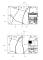
図1,図2は、本発明のシステムを構成する電子機器として好適な一実施形態であるレーダー探知機の構成を示している。レーダー探知機1は、薄型矩形状のケース本体2を備え、そのケース本体2の背面側下方に取り付けられたブラケット3を用いて車両のダッシュボード上等に貼り付けて固定される。
"Basic configuration of electronic devices"
1 and 2 show the configuration of a radar detector, which is a preferred embodiment of an electronic device that constitutes the system of the present invention. The
ケース本体2の前面(車両後方(運転者側)に向く面)には、表示部5を備える。表示部5は、3.2インチのカラーTFT液晶ディスプレイで構成する。この表示部5上には、表示部5のどの部分がタッチされたかを検出するタッチパネル6を備える。また、ケース本体2の前面の右サイドには音量調整ボタン7が配置され、同左サイドには各種の作業用ボタン8が配置される。
The front surface of the case body 2 (the surface facing the rear of the vehicle (the driver's side)) is equipped with a
ケース本体2の右側面には、着脱可能な記録媒体としてのメモリカードを装着するためのカード挿入口9を備え、ケース本体2内のカード挿入口9の内側にメモリカードリーダ10が内蔵される。このカード挿入口9からメモリカード11を挿入することで、そのメモリカード11はメモリカードリーダ10に装着される。メモリカードリーダ10は、装着されたメモリカード11に格納されたデータを制御部18へ渡す。より具体的には、制御部18が、メモリカード11に格納されたデータとして、新規な警報対象の情報(経度・緯度等の位置情報,種別情報等)などの更新情報がある場合、その更新情報をデータベース19に格納(ダウンロード)することで、データ更新がされる。
The right side of the
データベース19は、制御部18のマイコン内あるいはマイコンに外付けした不揮発性メモリ(たとえばEEPROM)により実現できる。なお、データベース19には、出荷時に地図データ並びに一定の警報対象に関する情報が登録されており、その後に追加された警報対象についてのデータ等が上記のようにしてデータ更新される。
The
ケース本体2の背面側中央上方の内部にGPS受信器13を配置し、さらにその横にマイクロ波受信器14,無線受信器15を配置する。GPS受信器13は、GPS衛星からのGPS信号を受信し、現在位置(経度・緯度)情報を出力する。マイクロ波受信器14は、速度測定装置から出射される所定周波数のマイクロ波を受信する。無線受信器15は、飛来する所定周波数の無線を受信する。ケース本体2内の下方には、スピーカ16も内蔵している。スピーカ口は、ケース本体2の底面に設けている。
A
ケース本体2の背面側下方には、DCジャック17を配置する。このDCジャック17は、図示省略のシガープラグコードを接続するためのもので、そのシガープラグコードを介して車両のシガーソケットに接続して電源供給を受け得るようにする。
A
また、制御部18は、CPU,ROM,RAM,不揮発性メモリ、I/O等を備えるマイコンであり、図2に示すように上述した各部と接続され、上記の各種の入力機器(タッチパネル6、GPS受信器13、マイクロ波受信器14、無線受信器15等)から入力される情報に基づき所定の処理を実行し、出力機器(表示部5,スピーカ16等)を利用して所定の警報・メッセージを出力する。これらの基本構成は、基本的に従来のものと同様のものを用いることができる。
The
本実施形態のレーダー探知機1における機能は、制御部18に有するコンピュータが実行するプログラムとして制御部18のEEPROM上に格納され、これを制御部18に有するコンピュータが実行することで実現する。制御部18の有するプログラムによってコンピュータが実現する機能としては、GPSログ機能、待ち受け画面表示機能、レーダースコープ表示機能、GPS警報機能、レーダー波警報機能、無線警報機能などがある。
The functions of the
GPSログ機能は、制御部18が1秒ごとにGPS受信器8によって検出された現在位置をその検出した時刻および速度(車速)と関連づけて位置履歴として不揮発性メモリに記憶する機能である。この位置履歴は例えばNMEA形式で記録する。
The GPS log function is a function in which the
待ち受け画面表示機能は、所定の待ち受け画面を表示部5に表示する機能である。図3(a)は、待ち受け画面の一例を示しており、ここではGPS受信器13によって検出した自車両の速度、緯度、経度、高度を示している。
The standby screen display function is a function for displaying a predetermined standby screen on the
MAP表示機能は、図3(b)に示すように、GPS受信器13によって検出した現在位置に基づき、データベース19にアクセスし、そこに記憶されている地図データを読み出して表示する機能である。また、MAP表示機能は、現在位置の周囲の警報対象をデータベース19に記憶された位置情報に基づいて検索し、周囲に警報対象が存在する場合に地図上の該当する位置にその警報対象を示す情報(ターゲットアイコン112等)を重ねて表示する機能も備える。具体的な表示態様は、以下の通りである。
As shown in FIG. 3(b), the MAP display function is a function that accesses the
制御部18は、表示部5のほぼ全面のメイン表示領域R1に、車両の進行方向が常に上を向くように地図を表示する。制御部18は、メイン表示領域R1の下側中央が現在の自車位置になるように地図を表示するとともに、当該位置に自車アイコン111を表示する。
The
制御部18は、メイン表示領域R1の上方側に設定されたステータスエリアR2に、ステータス情報を表示する。ステータスエリアR2に表示するステータス情報は、左から順に、現在時刻121(図では、「15:10」),GPS電波受信レベル表示アイコン122(図では、長さの異なる3本の直線が平行に起立した最大受信レベル),駐車禁止エリアアイコン123(駐車最重点エリア,駐車重点エリア内のときに表示),レーダーの受信感度を示す受信感度モード表示アイコン124(図では、最高感度の「SE」)、車両速度125(図では「30km/h」)、方位磁針126となっている。ステータスエリアR2は、透明な領域とし、メイン表示領域R1のレイアよりも上のレイアを用いて配置する。これにより、ステータスエリアR2内でも、ステータス情報が表示されていない場所では、下側に位置する地図が視認できる。
The
制御部18は、メイン表示領域R1の左サイドに設定されるスケール表示領域R3に、現在のスケール情報(縮尺)を表示する。スケールは、自車位置を0mとし、その自車位置からメイン領域R1の上下方向の中間位置までの距離(図では「500」)と、上方位置までの距離(図では「1000」)を表示する。単位は、「m」である。制御部18は、メイン表示領域R1が2回連続してタッチされたことを検知すると、メイン表示領域R1内の所定位置(スケール表示領域R3に添う位置)に地図スケール変更ボタンを表示し(図示省略)、その地図スケール変更ボタンに対するタッチに応じて地図スケールを変更する。つまり、制御部18は、変更した地図スケールの縮尺に合わせてメイン表示領域R1に表示する地図の縮尺を変更すると共に、スケール表示領域R3に表示するスケール情報も変更する。
The
図3(a)に示すような待ち受け画面表示機能実行中に、表示部5への1回のタッチを検知した制御部18は、所定のメニュー画面を表示する。そのメニュー画面中に用意された画面切り替えボタンがタッチされたことを検知した制御部18は、図3(b)に示すようなMAP表示機能に切り替える。同様にMAP表示機能実行中に表示部5への1回のタッチを検知した制御部18は、所定のメニュー画面を表示する。そのメニュー画面中に用意された画面切り替えボタンがタッチされたことを検知した制御部18は、待ち受け画面表示機能に切り替える処理を行う。
When the
制御部18は、待ち受け画面表示機能、MAP表示機能(以下これらの機能を総称して待受機能と称する)の実行中に、発生したイベントに応じて、GPS警報機能、レーダー波警報機能、無線警報機能等の各機能を実現する処理を実行し、当該機能の処理終了時には元の待受機能の処理に戻る。各機能の優先度は、高いほうから、レーダー波警報機能、無線警報機能、GPS警報機能の順に設定している。
The
GPS警報機能は、制御部18に有するタイマーからのイベントにより所定時間間隔(1秒間隔)で実行される処理であり、データベース19に記憶された警報対象の緯度経度とGPS受信器13によって検出した現在位置の緯度経度から両者の距離を求め、求めた距離が所定の接近距離になった場合に、表示部5に図4(a)に示すようなGPS警報表示130(警報対象の模式図・残り距離等)をし、スピーカ16からその旨を示す接近警告の音声を出力する処理である。
The GPS alarm function is a process executed at a predetermined time interval (1 second intervals) in response to an event from a timer in the
こうした警報対象としては、居眠り運転事故地点、レーダー、制限速度切替りポイント、取締エリア、検問エリア、駐禁監視エリア、Nシステム、交通監視システム、交差点監視ポイント、信号無視抑止システム、警察署、事故多発エリア、車上狙い多発エリア、急/連続カーブ(高速道)、分岐/合流ポイント(高速道)、ETCレーン事前案内(高速道)、サービスエリア(高速道)、パーキングエリア(高速道)、ハイウェイオアシス(高速道)、スマートインターチェンジ(高速道)、PA/SA内
ガソリンスタンド(高速道)、トンネル(高速道)、ハイウェイラジオ受信エリア(高速道)、県境告知、道の駅、ビューポイントパーキング等があり、これらの警報対象の種別情報とその位置を示す緯度経度情報と表示部5に表示する模式図または写真のデータと音声データとを対応付けてデータベース19に記憶している。
Such alarm targets include locations of drowsy driving accidents, radar, speed limit change points, enforcement areas, checkpoints, parking ban monitoring areas, N systems, traffic monitoring systems, intersection monitoring points, traffic light ignoring prevention systems, police stations, accident-prone areas, vehicle theft-prone areas, sharp/continuous curves (expressway), branching/merging points (expressway), ETC lane advance guidance (expressway), service areas (expressway), parking areas (expressway), highway oases (expressway), smart interchanges (expressway), gas stations in PAs/SAs (expressway), tunnels (expressway), highway radio receiving areas (expressway), prefectural border announcements, roadside stations, view point parking, etc., and information on the type of alarm target, latitude and longitude information indicating its position, schematic diagram or photograph data to be displayed on the
図4(b)は、レーダー波警報機能の表示例を示している。このレーダー波警報機能は、マイクロ波受信器14によって速度測定装置(移動式レーダー等(以下、単に「レーダー」と称する))から発せられる周波数帯のマイクロ波に対応する信号が検出された場合に、表示部5に対して警報画面131を表示するとともに、スピーカ20から警報音を出力する警報機能である。例えば、レーダーの発するマイクロ波の周波数帯のマイクロ波がマイクロ波受信器4によって検出された場合に、図4(b)に示すように、データベース19に記憶されたレーダーの模式図または写真を表示部5に警報画面として表示するとともに、データベース19に記憶された音声データを読み出して「レーダーです。スピード注意」という音声をスピーカ16から出力する。
Figure 4(b) shows an example of the display of the radar wave warning function. This radar wave warning function is an alarm function that displays an
無線警報機能は、無線受信器15によって、緊急車両等の発する無線電波を受信した場合に、その走行等の妨げとならないよう、警報を発する機能である。無線警報機能においては、取締無線、カーロケ無線、デジタル無線、特小無線、署活系無線、警察電話、警察活動無線、レッカー無線、ヘリテレ無線、消防ヘリテレ無線、消防無線、救急無線、高速道路無線、警備無線等で用いられる無線信号の周波数をスキャンし、スキャンした周波数で、無線信号を受信した場合には、データベース19に無線種別ごとに記憶されたその周波数に対応する無線信号を受信した旨の模式図を警報画面として表示部5に表示するとともに、データベース19に無線種別ごとに記憶された音声データを読み出して、スピーカ16からその無線の種別を示す警報音声を出力する。たとえば、取締無線を受信した場合には「取締無線です。スピード注意」のように音声を出力する。
The radio warning function is a function that issues a warning when radio waves emitted by an emergency vehicle or the like are received by the radio receiver 15 so as not to interfere with the driving of the vehicle. The radio warning function scans the frequencies of radio signals used in police radio, car location radio, digital radio, special small radio, police station radio, police telephone, police activity radio, tow truck radio, helicopter radio, fire helicopter radio, fire radio, emergency radio, highway radio, security radio, etc., and when a radio signal is received at a scanned frequency, a schematic diagram indicating that a radio signal corresponding to the frequency stored in the
[カラーLEDを利用した警報機能]
以下、本発明の特徴であるカラーLEDを用いた警報機能を説明する。ケース本体2の前面の所定位置に、発光部21を設ける。この発光部21の設置位置は、表示部5の表示画面の更に上方の中央部としている。この発光部21に対向するケース本体2の内部には、カラーLED22が配置される。カラーLED22は、RGB3原色LED、すなわち、三原色のチップを内蔵したLEDである。Rが5ビット、Gが5ビット、Bが5ビットの合計で15bitとすると、32,768色の色制御の色制御をする。発光部21は、例えばケース本体2を構成する前壁面の該当領域を肉薄にしたり、半透明の部材を嵌め込んだりして、内蔵したカラーLED22の発光色が外部から見て分かるようにする。さらに、外部から見て発光部21が、1つの色を発光しているようにする。
[Warning function using color LED]
The warning function using the color LED, which is a feature of the present invention, will be described below. The
制御部18は、カラーLED22の発光状態の制御を行う。すなわち、データベース19には、警報対象と発光色情報を関係づけた関係情報が記憶保持されている。この関係情報は、警報対象に関する情報の一つとして、出荷時に登録されている。本実施形態では、個々の警報対象ごとに発光色情報を関係づけるのではなく、警報対象の種類毎に関係づけている。すなわち、GPS警報機能における警報対象とした上記に例示列挙した固定設置される速度測定装置(レーダー)、Nシステム、交通監視ポイント、検問エリア、道の駅などの種類毎に表示する発光色を特定する発光色情報を関係づける。さらに、レーダー波警報機能における警報対象である速度測定装置(警報条件は、所定の周波数帯のマイクロ波に対応する信号検出)に対応する発光色を特定する発光色情報、無線警報機能における検出対象である無線種別ごとに対応する発光色を特定する発光色情報を関係づける。
The
図5は、この発光部21(カラーLED22)の発光状態の制御を行う制御部18の機能を示している。制御部18における発光部21(カラーLED22)に対する発光状態の制御は、警報条件を満たす警報対象が存在した場合、その警報対象に対応する発光色でカラーLED22を発光させ、警報条件を満たす警報対象が複数存在する場合には、その中の1つを報知すべき警報対象(ターゲット)とし、そのターゲットとなった警報対象に対応する発光色でカラーLED22を発光させる。そして、具体的には、制御部18は、図5に示すフローチャートを実行する。
Figure 5 shows the function of the
まず、制御部18は、マイクロ波受信器14により所定のマイクロ波を受信したか否かを判断する(S1)。制御部18は、マイクロ波を受信した場合(S1がYes)、データベース19にアクセスし、警報対象と発光色情報を関係づけた関係情報内に記録されているマイクロ波受信に伴う速度測定装置に対応する発光色情報を取得し、カラーLED22がその発光色情報で特定される発光色Aで発光するように制御する。この発光色Aは、例えば、赤色など緊急度の高いことが分かるような色とすると良い。
First, the
一方、所定のマイクロ波を受信していない場合(S1がNo)、制御部18は、無線受信器15により所定の無線信号を受信したか否かを判断する(S3)。制御部18は、所定の無線信号を受信した場合(S3がYes)、データベース19にアクセスし、警報対象と発光色情報を関係づけた関係情報内に記録されている受信した無線信号の無線種別に対応する発光色情報を取得し、カラーLED22がその発光色情報で特定される発光色Bで発光するように制御する。この発光色Bは、実際には、無線種別により異なり、例えば無線種別の緊急度のレベルに合わせて、適宜の色が設定されている。
On the other hand, if the specified microwave is not received (S1 is No), the
また、無線種別によっては、赤色など緊急度の高いことが分かるような色を関連付けているが、この場合、上記のマイクロ波受信に伴う速度測定装置に関連付けられた発光色よりも緊急度が低いことが分かるような色とすると良い。緊急度が低いことが分かるような色とは、例えば、赤みが少なかったり、明度及びまたは輝度を落とすようにしたりするとよい。 Depending on the type of wireless communication, a color such as red may be associated to indicate a high level of urgency. In this case, it is preferable to use a color that indicates a lower level of urgency than the color of light associated with the speed measuring device associated with the microwave reception. A color that indicates a lower level of urgency may be, for example, less red or have reduced brightness and/or luminance.
一方、所定の無線信号を受信していない場合(S3がNo)、制御部18は、GPS受信器13で検出した現在位置情報を取得し、周囲に所定の接近関係にある警報対象があるか否かを判断する(S5)。すなわち制御部18は、取得した現在位置に基づき、データベース19にアクセスし、現在位置の周囲にターゲットとなる警報対象が存在するか否かを判断する。ターゲットとなる警報対象は、自車の周囲(例えば進行方向に対して所定の角度範囲内(例えば進行方向に対して左右それぞれ90度以下の角度とするとよく、特に45度以下とするとよい。)で半径Xm(Xは基準距離)の扇形の領域内など)に警報対象が1つ存在する場合、その警報対象がターゲットとなり、複数の警報対象が存在する場合、その中で条件を満たす1つがターゲットとなる。係る条件は、進行方向に対して所定の角度範囲内に有り、最も近いものとする。
On the other hand, if the specified wireless signal is not received (S3 is No), the
制御部18は、位置情報に基づきターゲットとなる警報対象が存在した場合(S5がYes)、データベース19にアクセスし、警報対象と発光色情報を関係づけた関係情報内に記録されているターゲットとなる警報対象の種類に対応する発光色情報を取得し、カラーLED22がその発光色情報で特定される発光色Cで発光するように制御する。この発光色Cは、実際には、警報対象の種類により異なる。速度測定装置のように速度測定装置などの重要度の高いものは赤色、Nシステムなどの重要度が中(注意を与える)のものは青色、道の駅などの需要度が低い(情報提供程度)ものは緑色などとするとよい。
When a target object to be warned is found based on the position information (Yes in S5), the
ドライバーは、運転中、前方その他の車両の周囲を注意する必要がある。本実施形態では、警報条件を満たした場合、発光部21が警報対象に対応する所定の発光色で発光するので、ドライバーは仮にレーダー探知機(発光部21)が視界に入っていなくても、発光したことはわかり、少し視線をずらすだけで視界内に発光部21をとらえ、その発光色を確認できる。これにより、警報条件を満たした警報対象が周囲に存在していること、並びにその警報対象が何であるか等について知ることができる。係る所定の発光色による警報は、カラーLED22を光源とする発光部21を用いているので、多数の警報情報が報知されるのではなく、また、所定の発光色で発光というシンプルな警報であるため、ドライバーは発光部を長時間注視することなくその警報内容を理解できるので、車両の内外の運転に必要な情報収集に注力できる。
While driving, the driver needs to pay attention to the vehicle ahead and other surroundings. In this embodiment, when the warning conditions are met, the light-emitting
[表示部を用いた警報の兼用]
上述したように、カラーLED22(発光部21)による警報を行う場合、表示部5による警報はしなくても良いし、併用して行っても良い。併用する場合、表示部5において表示されるターゲットアイコン112,GPS警報表示130,警報画面131を表示して報知する警報対象と、カラーLED22(発光部21)による所定の発光色を用いた警報をする警報対象(ターゲット)は同じにする。
[Double warning using display unit]
As described above, when an alarm is issued by the color LED 22 (light-emitting unit 21), an alarm by the
そして、制御部18は、警報条件を満たした場合に表示部5の背景色を変えることなく所定の発光状態にする制御をする。このように背景色を変えないので、表示部5に表示していた地図情報等が見づらくなることもなく、元々表示部5に表示しユーザに提供する情報の報知がそのまま行える。
Then, when the alarm conditions are met, the
さらに、本実施形態では、制御部18は、警報条件を満たした場合に表示部5に各種の警報情報を表示しているで、より具体的・詳細な内容をユーザに知らせることができる。この場合に、表示画面とは別に設けた発光部21の発光により警報対象の存在をユーザに知らせることができる。つまり、同一画面中に複数の情報が混在するのではなく、警報対象の存在は表示画面の外に設けた表示部で行い詳細な内容は表示画面を用いるので、警報対象の存在のみ知りたいユーザは、表示画面を見ることなく発光部21の発光状態から目的を達成することができ、詳細な内容まで知りたいユーザは、表示画面に表示された警報情報も見ることで目的が達成できるのでよい。
Furthermore, in this embodiment, the
さらにまた、制御部は、表示部5を用いた警報を行うに際し、文字情報を用いると良い。この場合に、その文字情報の色と発光部21の発光色とを同系色とするとよい。文字情報にすることで、内容をより理解しやすくなる。このとき、発光部21の発光色と文字情報の色を同系色にすることで、発光部21と警報情報(文字情報)の関連づけが強くなる。よって、ユーザは表示部5内に表示されている警報情報としての文字情報の存在位置を容易に見つけやすくなるので好ましい。
Furthermore, the control unit may use text information when issuing an alarm using the
[警報対象による発光色の変更の他の例]
上述した実施形態では、警報対象の種類に対応して発光色を変更したが、本発明はこれに限ることはなく、例えば位置情報に基づく警報対象の場合、位置情報が登録されている警報対象ごとに発光色を設定(関連付け)してもよいし、重要度(危険度)に応じて複数のグループに分けるとともにグループ毎に発光色を設定し、同一グループに属する警報対象は同じ発光色としても良い。
[Another example of changing the light emission color depending on the alarm target]
In the above-described embodiment, the light color is changed according to the type of alarm target, but the present invention is not limited to this. For example, in the case of alarm targets based on location information, a light color may be set (associated) for each alarm target whose location information is registered, or the alarm targets may be divided into multiple groups according to importance (risk level) and a light color may be set for each group, with alarm targets belonging to the same group being the same light color.
また、上述した実施形態では、無線警報機能による発光色Bにおいて、赤色を用いる場合、レーダー波警報機能による発光色Bの赤色よりも緊急度が低くなるような色としたが、同じ色でも良い。 In addition, in the above-described embodiment, when red is used as the light emission color B for the wireless warning function, it is a color that indicates a lower level of urgency than the red light emission color B for the radar wave warning function, but the same color may be used.
[警報レベルによる発光状態の変更]
上述した実施形態では、警報対象に対応して発光色を変更する発光状態の制御を行うようにしたが、本発明はこれに限ることはなく、警報レベルにより発光状態を変更しても良い。カラーLEDを用いることで、1つのLEDでもって多種類の色を表現することができる。よって、警報レベルが低い場合から高い場合まで、スムーズに階調制御を行うことで発光色が徐々に変化するような警報をすることができる。そして、警報レベルによる発光状態の変更は、上記のように発光色の変化に替え、あるは変化とともにカラーLED22の発光強度を変化させるようにしてもよい。発光強度の変更は、例えば制御部18が、発光色の明度や輝度を変えたり(例えば、輝度用PWMを用いる)、LEDの印加電圧を調整し発光量自体を変えたりすることで行う。発光強度を変える場合、たとえば、警報レベルが上がるほど、暗い色から明るい色に変化、或いは発光量を強く(大きく)していくようにすると良い。
[Change the lighting state according to the warning level]
In the above embodiment, the light emission state is controlled to change the light emission color in response to the alarm target, but the present invention is not limited to this, and the light emission state may be changed according to the alarm level. By using a color LED, many kinds of colors can be expressed with one LED. Therefore, an alarm can be issued in which the light emission color changes gradually from a low alarm level to a high alarm level by smoothly performing gradation control. The change in the light emission state according to the alarm level may be changed by changing the light emission intensity of the
係る警報レベルであるが、例えば警報条件が電波の受信とした場合、受信した電波の信号レベルとするとよい。速度測定装置から出射されるマイクロ波などの警報対象となる所定周波数の電波を受信した場合、受信した電波の信号レベルに対応して発光色や発光の強度を変更することで、無機質なデジタルレーダーレベルメータではなく受信した信号レベルをアナログ的に表現できる。 Regarding the alarm level, if the alarm condition is, for example, reception of radio waves, it is advisable to set it to the signal level of the received radio waves. When radio waves of a specific frequency that is the subject of an alarm, such as microwaves emitted from a speed measuring device, are received, the received signal level can be expressed in an analog manner, rather than an inorganic digital radar level meter, by changing the emission color and intensity according to the signal level of the received radio waves.
また、警報条件が現在位置と警報対象が接近関係にある場合、警報レベルは接近関係の程度としてもよい。接近関係の程度による制御は、例えば、距離が近づくほど警報レベルが高くなる制御をする。このようにすると、警報対象までのおおよその残り距離を理解できる。すなわち、図5における発光色Cの発光を行う場合、制御部18は、警報対象に基づく発光色をベースとし、警報対象までの残り距離に基づいて係る発光色を変える制御をする。
In addition, when the alarm condition is that the current position and the object to be warned are in close proximity, the alarm level may be the degree of closeness. Control based on the degree of closeness may be performed, for example, so that the alarm level becomes higher as the distance becomes closer. In this way, the approximate remaining distance to the object to be warned can be understood. In other words, when emitting light of color C in FIG. 5, the
さらに警報レベルは、上述した所定の電波の受信,接近関係以外にも、例えば、危険運転の程度や、燃費など各種のものがある。危険運転の程度は、例えば加速度センサを設け、その加速度センサのセンサ値が大きいほど危険運転の程度が高い、すなわち、警報レベルが高くなる設定とする。また、燃費は、急加速をするほど悪くなるので、加速度センサのセンサ値に基づき、センサ値が大きいほど燃費が悪い運転をしていると判定する。また、燃費は、車両から提供される車両情報により求めると良い。車両に実装されているOBD-II(IIはローマ数字の「2」であり、以下「OBD-II」を「OBD2」と記す)コネクタは、故障診断コネクタとも称され、車両のECUに接続され、各種の車両情報が出力される。そこで、ケース本体に、OBD2コネクタに接続する接続ケーブルを取り付け、MAF値(mass air flow:空気量),インジェクション開時間,スロットル開度,燃料流量,瞬間燃費,残燃料量,アクセル開度等の車両情報を取得する。制御部18は、例えばMAF値から燃費を求めたり、車両情報として出力される瞬間燃費等に基づいて現在の燃費を求めたりする。
In addition to the above-mentioned predetermined radio wave reception and proximity, there are various warning levels, such as the degree of dangerous driving and fuel economy. The degree of dangerous driving is determined by, for example, providing an acceleration sensor, and the higher the sensor value of the acceleration sensor, the higher the degree of dangerous driving, i.e., the higher the warning level. Furthermore, since fuel economy worsens the more rapid the acceleration, it is determined based on the sensor value of the acceleration sensor that the greater the sensor value, the worse the fuel economy of the driving. Furthermore, fuel economy can be obtained from vehicle information provided by the vehicle. The OBD-II (II is the Roman numeral "2", and "OBD-II" will be referred to as "OBD2" below) connector installed in the vehicle is also called a fault diagnosis connector, and is connected to the vehicle's ECU and outputs various vehicle information. Therefore, a connection cable that connects to the OBD2 connector is attached to the case body, and vehicle information such as MAF value (mass air flow), injection opening time, throttle opening, fuel flow rate, instantaneous fuel economy, remaining fuel amount, and accelerator opening is obtained. The
一方、警報レベルに対応した発光状態の変更であるが、例えば発光色の周波数を段階的に変えることで、発光色を変えるようにするとよい。周波数の変更をすることで発光色を連続的に変更できる。この場合に周波数の低い方を警報レベルが1、周波数の高い方を警報レベルが最大としてスムーズな階調制御をすると良い。 On the other hand, to change the light emission state in response to the alarm level, it is a good idea to change the light emission color by, for example, gradually changing the frequency of the light emission color. By changing the frequency, the light emission color can be changed continuously. In this case, it is a good idea to set the alarm level to 1 for the lower frequency and the maximum alarm level for the higher frequency to achieve smooth gradation control.
[音声による警報との併用]
制御手部は、警報条件を満たした場合にスピーカ16から音声による警報を行う機能を備える。そして制御部は、音声の強弱に対応してLEDの発光強度を変化させるとよい。警報条件を満たした場合、例えば、「1km先 ループコイルです 制限速度は60キロメートルです」や「すぐ先 Nシステムです」等といった警報対象についての情報を音声で報知すると、ドライバーは前方等を向いた状態でその内容を知ることができるので好ましい。この場合に音声の発音の強弱(例えば音量)に応じて、発光強度(明度・輝度等)を変化させることで、装置自体が意志を持って喋っている感覚になり、高級感が増すとともに面白みも増すのでよい。音声が強い(大きい)ほど発光強度も強く(大きく)なるようにすると良い。
[Combined with audio warning]
The control unit has a function of issuing a voice warning from the
[複合条件による警報]
警報条件は複数の条件(複合条件)とすると良い。この場合に制御部18は、複数の条件を全て充足する場合の発光状態と、複数の条件の一部を充足する場合の発光状態を異ならせるようにするとよい。一部の条件を充足している場合、その後に全部の条件を満たす可能性がある。よって、一部の条件を充足した際に前兆警報をすることでユーザに注意を与えるので良い。一部の条件を充足している際の発光状態は、全ての条件を充足する場合の発光状態よりも目立たない、おとなしめのものとすると良い。
[Alarm due to multiple conditions]
The warning conditions may be multiple conditions (composite conditions). In this case, the
例えば、複数の条件としては、「所定周波数のマイクロ波(電波)の受信」(条件1)と、「受信した信号レベルが基準値以上」(条件2)とした場合に、2つの条件を充足すると警報対象から発せられた電波を受信したとして所定の発光状態(例えば、赤色の発光)による警報をし、条件1のみ充足(信号レベルは基準値未満)の場合には異なる発光状態(例えば、青色の発光)による警報をする。警報対象までの距離が遠く、受信した信号レベルが基準値未満でも、更に走行して警報対象に接近することで信号レベルが基準値以上になることは良くある。係る場合に、予め前兆警報をすることで、ユーザに心の準備をさせ、全ての条件を満たした警報が発せられても慌てることなく安全運転できるようになるのでよい。
For example, if multiple conditions are "reception of microwaves (radio waves) of a specified frequency" (condition 1) and "received signal level is equal to or greater than a reference value" (condition 2), then if both conditions are met, a radio wave emitted from the target of the warning is received and a warning is issued in a specified light emission state (e.g., red light emission), whereas if
<その他>
上述した実施形態では、LEDが、Rが5ビット、Gが5ビット、Bが5ビットの合計で15bitで色制御されるものについて説明したが、ビット数はこれに限るものではなく、多くても良いし少なくても良い。各ビット数が増えるほど、色制御する色の数は増え、例えば、Rが8ビット、Gが8ビット、Bが8ビットの合計24ビットの合計24ビットとすれば、16,777,216色の色制御が可能となる。
<Other>
In the above embodiment, the LED is color-controlled by 15 bits in total, 5 bits for R, 5 bits for G, and 5 bits for B, but the number of bits is not limited to this and may be more or less. The more bits there are, the more colors can be controlled. For example, if R is 8 bits, G is 8 bits, and B is 8 bits, for a total of 24 bits, then 16,777,216 colors can be controlled.
上述した実施形態では、表示部5を設けるとともに、表示部5に地図を表示しているが、地図を表示しないものでも良いし、さらに、表示部がないものでも良い。
In the above-described embodiment, a
また、カラーLED22はケース本体11内に内蔵したが、本発明はこれに限ることはなく、カラーLED22が外部に露出していても良い。また、カラーLEDの設置数は任意である。要は、外から見て発光部21が1つの色を発光しているように見えればよい。
In addition, the
更に、実施形態では、発光部21の位置は、表示部5の表示画面の更に上方の中央部としたが、これに限ることはなく、表示画面の外側の上方で左右いずれかに偏らせた位置としても良いし、表示画面の外側であって、その横或いは下方としてもよい。
In addition, in the embodiment, the position of the light-emitting
また、発光部21は、図1では長方形の矩形領域としたが、その形状は任意であり、楕円形・円形その他各種の形状をとることができる。また、図6に示すように、発光部21を所定の文字(文字列)・記号・マークなどとしてもよい。図6では、発光部21を表示画面5の左側に設けた例を示し、更に、発光部21が商標のメーカー名その他のロゴで構成した例を示している。そして、このロゴからなる発光部21の裏側(ケース本体2の内部)にカラーLED22を配置する。この例では、ロゴの部分のみが状況に応じて様々な色で発光する。これは、例えば、ケース本体2を黒色などのプラスチック等、光が透過しない材料で形成し、ロゴの部分に内外に貫通するスリットや孔部を設ける。そして、係る孔部を光が透過する材料(透明・半透明のプラスチック等)からなる閉塞部材を嵌め込んで塞ぐ。これにより、孔部を介してちり・ほこり等がケース本体2内に進入するのを抑制しつつ、カラーLED22からの光が当該閉塞部材を通過して外部に至る。よって、ユーザは、外から見た場合に、閉塞部材すなわちロゴの部分が発光しているように見える。
Although the light-emitting
ここでは、ロゴ等の部分のみが発光するようにしたが、ロゴ等を含む周辺領域全体が発光するようにしてもよい。これは、例えば、図1に示した長方形の発光部21に、ロゴ等を印刷する。これにより、発光部21である調方形の領域全体が状況に応じて様々な色で発光し、その光によりロゴが浮き上がって見えて目立つ。
Here, only the logo and other parts are illuminated, but the entire surrounding area including the logo and other parts may be illuminated. For example, the logo and other parts may be printed on the rectangular light-emitting
図7,図8は、警報対象の種類と、それに対応付けられた色(LEDの発光色)との対応関係の一例を示している。図に示すように、LEDの発光色と対応付けられる警報対象は、大きく分けたジャンルとしては、レーダー(実施形態の「レーダー波警報機能」に対応)、無線(実施形態の「無線警報機能」に対応)、GPS(実施形態の「GPS警報機能」に対応)、システムがある。システムは、レーダー、無線、GPSのいずれにも該当しないその他の全てであり、発光色は白色としている。従って、音と連動して発光するようにした場合、制御部18は、3つのジャンルに該当しないその他の全ての音を出力する際とともに、カラーLEDを白色に発光する制御を行う。
Figures 7 and 8 show an example of the correspondence between the type of alarm target and the associated color (LED light color). As shown in the figure, the alarm targets associated with the LED light color are roughly divided into categories: radar (corresponding to the "radar wave alarm function" of the embodiment), wireless (corresponding to the "wireless alarm function" of the embodiment), GPS (corresponding to the "GPS alarm function" of the embodiment), and system. Systems are everything else that does not fall into any of the categories of radar, wireless, or GPS, and the light color is white. Therefore, when light is emitted in conjunction with sound, the
また、レーダーのジャンルに属する具体的な警報対象としては、所定のマイクロ波を受信した場合の通常警報と、一瞬で強い電波が発せられる特徴があるステルス波を検知した場合のステルス警報がある。そして、通常警報は、受信レベル(受信信号の信号強度)により5段階に色分けして警報する。受信レベルが最も小さいのが「通常警報 レベル1」で発光色は「黄緑」としている。以下順に受信レベルが大きくなるにつれて、「通常警報 レベル2」の発光色は「黄」「通常警報 レベル3」の発光色は「薄いオレンジ」、「通常警報 レベル4」の発光色は「オレンジ」、「通常警報 レベル5」の発光色は「赤」を対応付けている。このように、受信レベルが小さいレベル1のときは、緑系(黄緑)といった比較的安全なイメージのある色を用い、少しレベルが上がる(レベル2)と、注意を促すことで「黄」としている。そして、レベル3以降になると、赤色系の危険・警報を表すイメージのある色を用いてユーザに警報するようにしている。 さらに、ステルス警報は、青系から赤系に徐々に発光色を変化させその後青系に徐々に向けて発光色を変化する制御を行うようにした。
Specific warning targets in the radar category include a normal warning when a certain microwave is received, and a stealth warning when a stealth wave is detected, which is characterized by the instantaneous emission of a strong radio wave. The normal warning is color-coded into five levels according to the reception level (signal strength of the received signal). The lowest reception level is "
無線のジャンルにおける具体的な警報対象の種類(警報項目)と発光色の関係づけは、「取締無線:ピンク」,「カーロケ近接:ピンク」,「カーロケ遠方:黄」,「デジタル無線:黄」,「カーロケ圏外:水色」,「特小無線:水色」,「署活系無線:水色」,「警察無線:水色」「レッカー無線:水色」,「ヘリテレ無線:黄緑」,「消防ヘリテレ無線:黄緑」,「消防無線:黄緑」,「救急無線:黄緑」,「高速道路無線:黄緑」,「警備無線:黄緑」とした。 The relationship between the specific types of alarm targets (alarm items) and the light colors in the radio category is as follows: "Police radio: pink", "Car location close by: pink", "Car location far away: yellow", "Digital radio: yellow", "Car location out of range: light blue", "Small radio: light blue", "Station activity radio: light blue", "Police radio: light blue", "Tow truck radio: light blue", "Helicopter radio: yellow-green", "Fire helicopter radio: yellow-green", "Fire radio: yellow-green", "Emergency radio: yellow-green", "Highway radio: yellow-green", "Security radio: yellow-green".
GPSのジャンルにおける具体的な警報対象の種類(警報項目)と発光色の関係づけは、「オービス:赤」,「速度超過:赤」,「制限速度切り替え:黄」,「取締エリア:黄」,「検問エリア:黄」,「駐禁最重点エリア:黄」,「駐禁重点エリア:黄」,「高速交通警察隊:黄」,「交差点監視ポイント:黄」,「信号無視抑止システム:黄」,「マイエリア:黄」,「Nシステム:青」,「交通監視システム:青」,「警察署:青」,「事故多発エリア:青」,「車上狙い多発エリア:青」,「高速道 急・連続カーブ:青」,「高速道 合流・分岐ポイント:青」,「ETCレーン:緑」,「サービスエリア:緑」,「パーキングエリア:緑」,「ハイウェイオアシス:緑」,「高速道 長い・連続トンネル:緑」,「ハイウェイラジオ受信エリア:緑」,「県境:緑」,「道の駅:緑」,「ビューポイントパーキング:緑」とした。 In the GPS genre, the relationship between the specific types of warning targets (warning items) and the light colors is as follows: "Automatic speed camera: red", "Speeding: red", "Speed limit switching: yellow", "Enforcement areas: yellow", "Checkpoint areas: yellow", "Priority parking ban areas: yellow", "Priority parking ban areas: yellow", "Highway traffic police: yellow", "Intersection monitoring points: yellow", "Red light ignoring prevention system: yellow", "My area: yellow", "N system: blue", "Traffic monitoring system: blue", "Police station: blue", "Areas with high accident rates: blue", "Areas with high rates of vehicle theft: blue", "Expressway sharp and continuous curves: blue", "Expressway merging and branching points: blue", "ETC lanes: green", "Service areas: green", "Parking areas: green", "Highway oases: green", "Expressway "Long/continuous tunnel: green", "Highway radio reception area: green", "Prefectural border: green", "Roadside station: green", "Viewpoint parking: green".
上記の実施形態では、本発明のシステムの適用機器としてダッシュボードその他の車内の所定位置にブラケット3を用いて貼り付け等により固定設置するためイブのレーダー探知機を例に挙げて説明したが、ルームミラーに取り付けるミラータイプのレーダー探知機にも適用できる。更に、本発明はレーダー探知機に限ることはなく車載用の各種の電子機器の機能として実施することができる。たとえば、ナビゲーション装置等の機能として組み込んでもよい。
In the above embodiment, an Eve radar detector was used as an example of an applicable device for the system of the present invention, which is fixedly installed by attaching it to the dashboard or other predetermined position inside the vehicle using the
上述した実施形態並びに変形例では、装置内に各種の情報を記憶したデータベース19を備え、制御部18は係るデータベース19にアクセスして必要な情報を読み出し、各種の処理をしたが、本発明はこれに限ることはない。すなわち、データベース19に登録する情報の一部または全部をサーバに登録しておく。そして、レーダー探知機その他の電子機器・装置は、係るサーバと通信する機能を備え、制御部18は、適宜サーバにアクセスし、必要な情報を取得して処理を実行するシステムとしてもよい。係るサーバに制御部の一部または全部を実装し、サーバ側で処理の一部を実行させ車載機側ではその結果を取得し、所定の表示をするものでもよい。さらに、表示装置は、別の車載機器や車両に実装された装置のものを利用するものでもよい。
In the above-described embodiment and modified example, the device is provided with a
実施形態等では現在位置情報を検出するGPS受信器を内蔵したが、本発明ではGPS受信器を備える構成は必須ではなく、車両或いは他の車載機から現在位置情報を取得し、その取得した情報に基づいて警報対象との接近関係の有無の判断等をするものでも良い。 In the embodiments, a GPS receiver is built in to detect current location information, but the present invention does not require a GPS receiver. It is also possible to obtain current location information from the vehicle or other in-vehicle device, and use the obtained information to determine whether or not the vehicle is approaching the target of an alarm.
5 表示器
6 タッチパネル
7 音量と調整ボタン
8 作業ボタン
10 メモリカードリーダ
11 メモリカード
13 GPS受信器
14 マイクロ波受信器
15 無線受信器
16 スピーカ
18 制御部
19 データベース
21 発光部
22 カラーLED
5
Claims (4)
表示部と、
前記表示部の画面の外の所定位置に配置された発光部と、
車両の速度を測定する速度測定装置から発せられる所定周波数のマイクロ波を受信した場合に警報を出力する機能と、
前記マイクロ波を受信していない場合において所定の無線種別の無線電波を受信した場合に、前記表示部の画面の外の所定位置に配置された前記発光部を前記無線種別ごとに設定された色で発光させるとともに、前記画面における所定の領域に前記無線種別ごとに対応する模式図を表示させる機能を備え、
前記無線種別ごとに設定された色として、第一の色には複数の無線種別が割り当てられ、前記第一の色とは異なる色である第二の色には前記第一の色に割り当てられた複数の無線種別とは異なる複数の無線種別が割り当てられ、
前記所定の無線種別として、消防無線と、署活系無線を備え、
前記消防無線の受信の場合には前記第一の色で、前記署活系無線の受信の場合には前記第二の色で、前記表示部の画面の外の所定位置に配置された発光部を発光させる機能
を有するシステム。 A system that issues an alarm when a radio wave of a predetermined radio type is received,
A display unit;
A light emitting unit disposed at a predetermined position outside the screen of the display unit;
a function of outputting an alarm when a microwave having a predetermined frequency is received from a speed measuring device that measures the speed of a vehicle;
a function of, when receiving radio waves of a predetermined radio type while not receiving the microwaves, making the light-emitting unit arranged at a predetermined position outside the screen of the display unit emit light in a color set for the radio type, and displaying a schematic diagram corresponding to the radio type in a predetermined area on the screen,
As the colors set for the respective wireless types, a first color is assigned to a plurality of wireless types, and a second color different from the first color is assigned to a plurality of wireless types different from the plurality of wireless types assigned to the first color,
The predetermined radio types include a fire radio and a police station activity radio,
A system having a function of illuminating an illumination unit located at a predetermined position outside the screen of the display unit in the first color when receiving a fire department radio signal, and in the second color when receiving a police station radio signal.
Priority Applications (2)
| Application Number | Priority Date | Filing Date | Title |
|---|---|---|---|
| JP2023028071A JP7668552B2 (en) | 2019-09-17 | 2023-02-27 | System and Program |
| JP2025063434A JP2025106434A (en) | 2019-09-17 | 2025-04-08 | System and Program |
Applications Claiming Priority (3)
| Application Number | Priority Date | Filing Date | Title |
|---|---|---|---|
| JP2019167912A JP7266296B2 (en) | 2019-09-17 | 2019-09-17 | System and program |
| JP2021174433A JP2022028678A (en) | 2019-09-17 | 2021-10-26 | System and program |
| JP2023028071A JP7668552B2 (en) | 2019-09-17 | 2023-02-27 | System and Program |
Related Parent Applications (1)
| Application Number | Title | Priority Date | Filing Date |
|---|---|---|---|
| JP2021174433A Division JP2022028678A (en) | 2019-09-17 | 2021-10-26 | System and program |
Related Child Applications (1)
| Application Number | Title | Priority Date | Filing Date |
|---|---|---|---|
| JP2025063434A Division JP2025106434A (en) | 2019-09-17 | 2025-04-08 | System and Program |
Publications (2)
| Publication Number | Publication Date |
|---|---|
| JP2023062197A JP2023062197A (en) | 2023-05-02 |
| JP7668552B2 true JP7668552B2 (en) | 2025-04-25 |
Family
ID=71106935
Family Applications (5)
| Application Number | Title | Priority Date | Filing Date |
|---|---|---|---|
| JP2019167912A Active JP7266296B2 (en) | 2019-09-17 | 2019-09-17 | System and program |
| JP2021174433A Pending JP2022028678A (en) | 2019-09-17 | 2021-10-26 | System and program |
| JP2022095456A Active JP7382667B2 (en) | 2019-09-17 | 2022-06-14 | System and program |
| JP2023028071A Active JP7668552B2 (en) | 2019-09-17 | 2023-02-27 | System and Program |
| JP2025063434A Pending JP2025106434A (en) | 2019-09-17 | 2025-04-08 | System and Program |
Family Applications Before (3)
| Application Number | Title | Priority Date | Filing Date |
|---|---|---|---|
| JP2019167912A Active JP7266296B2 (en) | 2019-09-17 | 2019-09-17 | System and program |
| JP2021174433A Pending JP2022028678A (en) | 2019-09-17 | 2021-10-26 | System and program |
| JP2022095456A Active JP7382667B2 (en) | 2019-09-17 | 2022-06-14 | System and program |
Family Applications After (1)
| Application Number | Title | Priority Date | Filing Date |
|---|---|---|---|
| JP2025063434A Pending JP2025106434A (en) | 2019-09-17 | 2025-04-08 | System and Program |
Country Status (1)
| Country | Link |
|---|---|
| JP (5) | JP7266296B2 (en) |
Citations (9)
| Publication number | Priority date | Publication date | Assignee | Title |
|---|---|---|---|---|
| JP2001175974A (en) | 1999-12-22 | 2001-06-29 | Nohmi Bosai Ltd | House information panel and disaster prevention panel |
| JP2005196312A (en) | 2003-12-26 | 2005-07-21 | Kikutaka Asaga | Operation switch illuminating device, electronic equipment and lighting system |
| JP2005242943A (en) | 2004-02-27 | 2005-09-08 | Yupiteru Ind Co Ltd | Traffic control warning device |
| JP2008250628A (en) | 2007-03-30 | 2008-10-16 | Maruhama:Kk | Radar detection device |
| US20100238026A1 (en) | 2009-03-19 | 2010-09-23 | Michael Batten | Mobile Electronic Detection Device With User Selectable Alerts |
| JP2010223620A (en) | 2009-03-19 | 2010-10-07 | Yupiteru Corp | Vehicle-mounted electronic apparatus and program |
| JP2010241383A (en) | 2009-04-09 | 2010-10-28 | Yupiteru Corp | On-vehicle electronic equipment and program |
| JP2010285097A (en) | 2009-06-12 | 2010-12-24 | Yupiteru Corp | Target detecting apparatus |
| JP2011100409A (en) | 2009-11-09 | 2011-05-19 | Yupiteru Corp | In-vehicle electronic apparatus and program |
Family Cites Families (29)
| Publication number | Priority date | Publication date | Assignee | Title |
|---|---|---|---|---|
| JPS5754866A (en) * | 1980-09-19 | 1982-04-01 | Matsushita Electric Ind Co Ltd | Speed alarm device |
| JPS62254178A (en) * | 1986-04-28 | 1987-11-05 | ソニー株式会社 | Panel apparatus |
| JPH0540166A (en) * | 1991-08-07 | 1993-02-19 | Yupiteru Kogyo Kk | Vehicle speed interlocking-type microwave detection device |
| JPH05276415A (en) * | 1992-03-27 | 1993-10-22 | Sony Corp | Telecamera |
| JPH07286858A (en) * | 1994-04-20 | 1995-10-31 | Hitachi Ltd | Obstacle detection device and navigation device including obstacle detection device |
| JPH0953955A (en) * | 1995-06-07 | 1997-02-25 | Toyoda Gosei Co Ltd | Meter for vehicle |
| JPH1114390A (en) * | 1997-06-20 | 1999-01-22 | Yamaha Motor Co Ltd | Route guidance method by navigation device |
| JP2000289525A (en) | 1999-04-01 | 2000-10-17 | Koichiro Tabuchi | Automotive warning light having high recognizing property |
| JP2001133539A (en) * | 1999-11-09 | 2001-05-18 | Funai Electric Co Ltd | Radar detection system |
| JP2001143189A (en) * | 1999-11-17 | 2001-05-25 | Funai Electric Co Ltd | Radar |
| JP3626390B2 (en) * | 2000-04-10 | 2005-03-09 | ユピテル工業株式会社 | Microwave detector |
| JP2002240765A (en) * | 2001-02-13 | 2002-08-28 | Yamaha Motor Co Ltd | Electric vehicle |
| JP4262083B2 (en) | 2003-12-25 | 2009-05-13 | キャタピラージャパン株式会社 | Overheat prevention structure for construction machine monitors |
| JP2006013938A (en) * | 2004-06-25 | 2006-01-12 | Funai Electric Co Ltd | Display device |
| JP4582012B2 (en) * | 2006-01-30 | 2010-11-17 | ソニー株式会社 | Operation panel device and display |
| JP4864911B2 (en) | 2007-02-09 | 2012-02-01 | 株式会社ユピテル | Target detection apparatus and program |
| JP5032180B2 (en) * | 2007-03-31 | 2012-09-26 | 渉 堀川 | Eco-drive support device, car navigation system and eco-drive support program |
| JP2009042972A (en) * | 2007-08-08 | 2009-02-26 | Cellstar Kogyo Kk | Receiving apparatus of road traffic information |
| JP4980177B2 (en) * | 2007-09-03 | 2012-07-18 | 象印マホービン株式会社 | Heating device and method for determining acceptance of operation of heating device |
| JP5150858B2 (en) | 2008-01-18 | 2013-02-27 | 株式会社ユピテル | Automotive electronic equipment and hinge parts |
| JP2009290846A (en) * | 2008-06-02 | 2009-12-10 | Yupiteru Corp | Microwave detector |
| JP4689725B2 (en) * | 2008-08-29 | 2011-05-25 | 株式会社ユピテル | In-vehicle electronic device and program |
| JP5326536B2 (en) * | 2008-12-11 | 2013-10-30 | 船井電機株式会社 | Liquid crystal display |
| JP4677485B2 (en) | 2008-12-25 | 2011-04-27 | 株式会社ユピテル | Traffic monitoring point detection device and program |
| JP4834741B2 (en) | 2009-01-07 | 2011-12-14 | 株式会社ユピテル | Target detection apparatus and program |
| JP5288350B2 (en) * | 2009-01-23 | 2013-09-11 | 株式会社ユピテル | Target detection apparatus and program |
| JP5316990B2 (en) | 2009-03-23 | 2013-10-16 | 株式会社ユピテル | In-vehicle electronic device and program |
| JP5312290B2 (en) * | 2009-10-28 | 2013-10-09 | 京セラ株式会社 | Portable electronic devices |
| JP4880061B2 (en) * | 2010-10-04 | 2012-02-22 | 株式会社ユピテル | Traffic monitoring point detection device and program |
-
2019
- 2019-09-17 JP JP2019167912A patent/JP7266296B2/en active Active
-
2021
- 2021-10-26 JP JP2021174433A patent/JP2022028678A/en active Pending
-
2022
- 2022-06-14 JP JP2022095456A patent/JP7382667B2/en active Active
-
2023
- 2023-02-27 JP JP2023028071A patent/JP7668552B2/en active Active
-
2025
- 2025-04-08 JP JP2025063434A patent/JP2025106434A/en active Pending
Patent Citations (9)
| Publication number | Priority date | Publication date | Assignee | Title |
|---|---|---|---|---|
| JP2001175974A (en) | 1999-12-22 | 2001-06-29 | Nohmi Bosai Ltd | House information panel and disaster prevention panel |
| JP2005196312A (en) | 2003-12-26 | 2005-07-21 | Kikutaka Asaga | Operation switch illuminating device, electronic equipment and lighting system |
| JP2005242943A (en) | 2004-02-27 | 2005-09-08 | Yupiteru Ind Co Ltd | Traffic control warning device |
| JP2008250628A (en) | 2007-03-30 | 2008-10-16 | Maruhama:Kk | Radar detection device |
| US20100238026A1 (en) | 2009-03-19 | 2010-09-23 | Michael Batten | Mobile Electronic Detection Device With User Selectable Alerts |
| JP2010223620A (en) | 2009-03-19 | 2010-10-07 | Yupiteru Corp | Vehicle-mounted electronic apparatus and program |
| JP2010241383A (en) | 2009-04-09 | 2010-10-28 | Yupiteru Corp | On-vehicle electronic equipment and program |
| JP2010285097A (en) | 2009-06-12 | 2010-12-24 | Yupiteru Corp | Target detecting apparatus |
| JP2011100409A (en) | 2009-11-09 | 2011-05-19 | Yupiteru Corp | In-vehicle electronic apparatus and program |
Also Published As
| Publication number | Publication date |
|---|---|
| JP7266296B2 (en) | 2023-04-28 |
| JP2023062197A (en) | 2023-05-02 |
| JP2020098564A (en) | 2020-06-25 |
| JP2025106434A (en) | 2025-07-15 |
| JP2022141635A (en) | 2022-09-29 |
| JP7382667B2 (en) | 2023-11-17 |
| JP2022028678A (en) | 2022-02-16 |
Similar Documents
| Publication | Publication Date | Title |
|---|---|---|
| JP5114814B2 (en) | System and program | |
| JP7696170B2 (en) | Systems and programs | |
| JP2024038388A (en) | Device | |
| JP2024069235A (en) | Electronic devices and programs | |
| JP6427779B2 (en) | Vehicle system and program | |
| JP6155495B2 (en) | Vehicle system and program | |
| JP6118972B2 (en) | System and program | |
| JP5201645B2 (en) | System and program | |
| JP2025106539A (en) | Equipment etc. | |
| JP7668552B2 (en) | System and Program | |
| JP6155443B2 (en) | Vehicle system and program | |
| JP6600864B2 (en) | System and program | |
| JP6316360B2 (en) | System and program | |
| JP6533923B2 (en) | Device and program | |
| JP2024099499A (en) | System and program and the like | |
| JP2024079738A (en) | In-Vehicle Electronics | |
| JP2019049726A (en) | Vehicle system and program | |
| JP6766294B2 (en) | Electronics | |
| JP2021054403A (en) | System and program for vehicle | |
| JP7716081B2 (en) | Systems and programs | |
| JP7627970B2 (en) | Vehicle system and program | |
| JP2025061527A (en) | System, receiving device and program | |
| JP2018091853A (en) | Vehicle system and program | |
| JP2014215642A (en) | Device |
Legal Events
| Date | Code | Title | Description |
|---|---|---|---|
| A521 | Request for written amendment filed |
Free format text: JAPANESE INTERMEDIATE CODE: A523 Effective date: 20230322 |
|
| A621 | Written request for application examination |
Free format text: JAPANESE INTERMEDIATE CODE: A621 Effective date: 20230322 |
|
| A977 | Report on retrieval |
Free format text: JAPANESE INTERMEDIATE CODE: A971007 Effective date: 20231114 |
|
| A131 | Notification of reasons for refusal |
Free format text: JAPANESE INTERMEDIATE CODE: A131 Effective date: 20240109 |
|
| A521 | Request for written amendment filed |
Free format text: JAPANESE INTERMEDIATE CODE: A523 Effective date: 20240310 |
|
| A131 | Notification of reasons for refusal |
Free format text: JAPANESE INTERMEDIATE CODE: A131 Effective date: 20240702 |
|
| A521 | Request for written amendment filed |
Free format text: JAPANESE INTERMEDIATE CODE: A523 Effective date: 20240902 |
|
| A131 | Notification of reasons for refusal |
Free format text: JAPANESE INTERMEDIATE CODE: A131 Effective date: 20241112 |
|
| A521 | Request for written amendment filed |
Free format text: JAPANESE INTERMEDIATE CODE: A523 Effective date: 20250109 |
|
| TRDD | Decision of grant or rejection written | ||
| A01 | Written decision to grant a patent or to grant a registration (utility model) |
Free format text: JAPANESE INTERMEDIATE CODE: A01 Effective date: 20250311 |
|
| A61 | First payment of annual fees (during grant procedure) |
Free format text: JAPANESE INTERMEDIATE CODE: A61 Effective date: 20250408 |
|
| R150 | Certificate of patent or registration of utility model |
Ref document number: 7668552 Country of ref document: JP Free format text: JAPANESE INTERMEDIATE CODE: R150 |