JP7653757B2 - Tube container - Google Patents
Tube container Download PDFInfo
- Publication number
- JP7653757B2 JP7653757B2 JP2018161743A JP2018161743A JP7653757B2 JP 7653757 B2 JP7653757 B2 JP 7653757B2 JP 2018161743 A JP2018161743 A JP 2018161743A JP 2018161743 A JP2018161743 A JP 2018161743A JP 7653757 B2 JP7653757 B2 JP 7653757B2
- Authority
- JP
- Japan
- Prior art keywords
- layer
- resin layer
- polyethylene
- reinforcing tape
- thickness
- Prior art date
- Legal status (The legal status is an assumption and is not a legal conclusion. Google has not performed a legal analysis and makes no representation as to the accuracy of the status listed.)
- Active
Links
- 239000010410 layer Substances 0.000 claims description 215
- 230000003014 reinforcing effect Effects 0.000 claims description 93
- 239000011241 protective layer Substances 0.000 claims description 46
- 229920013716 polyethylene resin Polymers 0.000 claims description 40
- 239000011888 foil Substances 0.000 claims description 38
- -1 polyethylene terephthalate Polymers 0.000 claims description 30
- 230000004888 barrier function Effects 0.000 claims description 22
- 229920000139 polyethylene terephthalate Polymers 0.000 claims description 20
- 239000005020 polyethylene terephthalate Substances 0.000 claims description 20
- 239000000463 material Substances 0.000 claims description 19
- 238000003860 storage Methods 0.000 claims description 19
- 229920005678 polyethylene based resin Polymers 0.000 claims description 16
- 229910052751 metal Inorganic materials 0.000 claims description 14
- 239000002184 metal Substances 0.000 claims description 14
- 239000000470 constituent Substances 0.000 claims description 4
- 229910052782 aluminium Inorganic materials 0.000 description 47
- XAGFODPZIPBFFR-UHFFFAOYSA-N aluminium Chemical compound [Al] XAGFODPZIPBFFR-UHFFFAOYSA-N 0.000 description 47
- 229920005989 resin Polymers 0.000 description 41
- 239000011347 resin Substances 0.000 description 41
- 239000004698 Polyethylene Substances 0.000 description 25
- 229920000573 polyethylene Polymers 0.000 description 25
- 239000012790 adhesive layer Substances 0.000 description 24
- 210000001503 joint Anatomy 0.000 description 24
- 238000007740 vapor deposition Methods 0.000 description 17
- 229920005672 polyolefin resin Polymers 0.000 description 13
- 229920002799 BoPET Polymers 0.000 description 12
- 238000007646 gravure printing Methods 0.000 description 10
- 239000004700 high-density polyethylene Substances 0.000 description 10
- 229920001684 low density polyethylene Polymers 0.000 description 10
- 239000004702 low-density polyethylene Substances 0.000 description 10
- 238000007789 sealing Methods 0.000 description 10
- 229920001903 high density polyethylene Polymers 0.000 description 9
- 238000005299 abrasion Methods 0.000 description 7
- 238000012360 testing method Methods 0.000 description 7
- 238000003466 welding Methods 0.000 description 7
- 229920010126 Linear Low Density Polyethylene (LLDPE) Polymers 0.000 description 5
- QVGXLLKOCUKJST-UHFFFAOYSA-N atomic oxygen Chemical compound [O] QVGXLLKOCUKJST-UHFFFAOYSA-N 0.000 description 5
- 229920000092 linear low density polyethylene Polymers 0.000 description 5
- 239000004707 linear low-density polyethylene Substances 0.000 description 5
- 239000001301 oxygen Substances 0.000 description 5
- 229910052760 oxygen Inorganic materials 0.000 description 5
- 230000002093 peripheral effect Effects 0.000 description 5
- XLYOFNOQVPJJNP-UHFFFAOYSA-N water Chemical compound O XLYOFNOQVPJJNP-UHFFFAOYSA-N 0.000 description 5
- 230000000052 comparative effect Effects 0.000 description 4
- 238000005034 decoration Methods 0.000 description 4
- 238000002844 melting Methods 0.000 description 4
- 230000008018 melting Effects 0.000 description 4
- BASFCYQUMIYNBI-UHFFFAOYSA-N platinum Chemical compound [Pt] BASFCYQUMIYNBI-UHFFFAOYSA-N 0.000 description 4
- 230000003746 surface roughness Effects 0.000 description 4
- BQCADISMDOOEFD-UHFFFAOYSA-N Silver Chemical compound [Ag] BQCADISMDOOEFD-UHFFFAOYSA-N 0.000 description 3
- 238000005452 bending Methods 0.000 description 3
- 230000007547 defect Effects 0.000 description 3
- 230000002542 deteriorative effect Effects 0.000 description 3
- 238000010586 diagram Methods 0.000 description 3
- PCHJSUWPFVWCPO-UHFFFAOYSA-N gold Chemical compound [Au] PCHJSUWPFVWCPO-UHFFFAOYSA-N 0.000 description 3
- 238000007542 hardness measurement Methods 0.000 description 3
- 238000004519 manufacturing process Methods 0.000 description 3
- 238000003825 pressing Methods 0.000 description 3
- RYGMFSIKBFXOCR-UHFFFAOYSA-N Copper Chemical compound [Cu] RYGMFSIKBFXOCR-UHFFFAOYSA-N 0.000 description 2
- PXHVJJICTQNCMI-UHFFFAOYSA-N Nickel Chemical compound [Ni] PXHVJJICTQNCMI-UHFFFAOYSA-N 0.000 description 2
- ATJFFYVFTNAWJD-UHFFFAOYSA-N Tin Chemical compound [Sn] ATJFFYVFTNAWJD-UHFFFAOYSA-N 0.000 description 2
- RTAQQCXQSZGOHL-UHFFFAOYSA-N Titanium Chemical compound [Ti] RTAQQCXQSZGOHL-UHFFFAOYSA-N 0.000 description 2
- 239000000853 adhesive Substances 0.000 description 2
- 230000001070 adhesive effect Effects 0.000 description 2
- 239000011889 copper foil Substances 0.000 description 2
- 238000012937 correction Methods 0.000 description 2
- 230000006866 deterioration Effects 0.000 description 2
- 238000002845 discoloration Methods 0.000 description 2
- 239000007789 gas Substances 0.000 description 2
- 238000000034 method Methods 0.000 description 2
- 238000012986 modification Methods 0.000 description 2
- 230000004048 modification Effects 0.000 description 2
- 238000011160 research Methods 0.000 description 2
- 239000004278 EU approved seasoning Substances 0.000 description 1
- 239000004743 Polypropylene Substances 0.000 description 1
- HCHKCACWOHOZIP-UHFFFAOYSA-N Zinc Chemical compound [Zn] HCHKCACWOHOZIP-UHFFFAOYSA-N 0.000 description 1
- 230000005540 biological transmission Effects 0.000 description 1
- 230000000903 blocking effect Effects 0.000 description 1
- 238000000748 compression moulding Methods 0.000 description 1
- 239000002537 cosmetic Substances 0.000 description 1
- 230000007423 decrease Effects 0.000 description 1
- 238000000151 deposition Methods 0.000 description 1
- 229940079593 drug Drugs 0.000 description 1
- 239000003814 drug Substances 0.000 description 1
- 238000011156 evaluation Methods 0.000 description 1
- 235000011194 food seasoning agent Nutrition 0.000 description 1
- 229910052737 gold Inorganic materials 0.000 description 1
- 239000010931 gold Substances 0.000 description 1
- 238000003475 lamination Methods 0.000 description 1
- 229920004889 linear high-density polyethylene Polymers 0.000 description 1
- 238000000691 measurement method Methods 0.000 description 1
- 238000001465 metallisation Methods 0.000 description 1
- 238000000465 moulding Methods 0.000 description 1
- 229910052759 nickel Inorganic materials 0.000 description 1
- 239000003960 organic solvent Substances 0.000 description 1
- 229910052697 platinum Inorganic materials 0.000 description 1
- 229920001155 polypropylene Polymers 0.000 description 1
- 238000007639 printing Methods 0.000 description 1
- 230000002787 reinforcement Effects 0.000 description 1
- 238000005096 rolling process Methods 0.000 description 1
- 229910052709 silver Inorganic materials 0.000 description 1
- 239000004332 silver Substances 0.000 description 1
- 229940034610 toothpaste Drugs 0.000 description 1
- 239000000606 toothpaste Substances 0.000 description 1
- 229910052725 zinc Inorganic materials 0.000 description 1
- 239000011701 zinc Substances 0.000 description 1
Images


Classifications
-
- B—PERFORMING OPERATIONS; TRANSPORTING
- B65—CONVEYING; PACKING; STORING; HANDLING THIN OR FILAMENTARY MATERIAL
- B65D—CONTAINERS FOR STORAGE OR TRANSPORT OF ARTICLES OR MATERIALS, e.g. BAGS, BARRELS, BOTTLES, BOXES, CANS, CARTONS, CRATES, DRUMS, JARS, TANKS, HOPPERS, FORWARDING CONTAINERS; ACCESSORIES, CLOSURES, OR FITTINGS THEREFOR; PACKAGING ELEMENTS; PACKAGES
- B65D35/00—Pliable tubular containers adapted to be permanently or temporarily deformed to expel contents, e.g. collapsible tubes for toothpaste or other plastic or semi-liquid material; Holders therefor
- B65D35/02—Body construction
- B65D35/10—Body construction made by uniting or interconnecting two or more components
-
- B—PERFORMING OPERATIONS; TRANSPORTING
- B65—CONVEYING; PACKING; STORING; HANDLING THIN OR FILAMENTARY MATERIAL
- B65D—CONTAINERS FOR STORAGE OR TRANSPORT OF ARTICLES OR MATERIALS, e.g. BAGS, BARRELS, BOTTLES, BOXES, CANS, CARTONS, CRATES, DRUMS, JARS, TANKS, HOPPERS, FORWARDING CONTAINERS; ACCESSORIES, CLOSURES, OR FITTINGS THEREFOR; PACKAGING ELEMENTS; PACKAGES
- B65D35/00—Pliable tubular containers adapted to be permanently or temporarily deformed to expel contents, e.g. collapsible tubes for toothpaste or other plastic or semi-liquid material; Holders therefor
- B65D35/02—Body construction
- B65D35/04—Body construction made in one piece
- B65D35/08—Body construction made in one piece from plastics material
-
- B—PERFORMING OPERATIONS; TRANSPORTING
- B32—LAYERED PRODUCTS
- B32B—LAYERED PRODUCTS, i.e. PRODUCTS BUILT-UP OF STRATA OF FLAT OR NON-FLAT, e.g. CELLULAR OR HONEYCOMB, FORM
- B32B1/00—Layered products having a non-planar shape
- B32B1/08—Tubular products
-
- B—PERFORMING OPERATIONS; TRANSPORTING
- B32—LAYERED PRODUCTS
- B32B—LAYERED PRODUCTS, i.e. PRODUCTS BUILT-UP OF STRATA OF FLAT OR NON-FLAT, e.g. CELLULAR OR HONEYCOMB, FORM
- B32B15/00—Layered products comprising a layer of metal
- B32B15/04—Layered products comprising a layer of metal comprising metal as the main or only constituent of a layer, which is next to another layer of the same or of a different material
- B32B15/08—Layered products comprising a layer of metal comprising metal as the main or only constituent of a layer, which is next to another layer of the same or of a different material of synthetic resin
- B32B15/085—Layered products comprising a layer of metal comprising metal as the main or only constituent of a layer, which is next to another layer of the same or of a different material of synthetic resin comprising polyolefins
-
- B—PERFORMING OPERATIONS; TRANSPORTING
- B32—LAYERED PRODUCTS
- B32B—LAYERED PRODUCTS, i.e. PRODUCTS BUILT-UP OF STRATA OF FLAT OR NON-FLAT, e.g. CELLULAR OR HONEYCOMB, FORM
- B32B15/00—Layered products comprising a layer of metal
- B32B15/04—Layered products comprising a layer of metal comprising metal as the main or only constituent of a layer, which is next to another layer of the same or of a different material
- B32B15/08—Layered products comprising a layer of metal comprising metal as the main or only constituent of a layer, which is next to another layer of the same or of a different material of synthetic resin
- B32B15/09—Layered products comprising a layer of metal comprising metal as the main or only constituent of a layer, which is next to another layer of the same or of a different material of synthetic resin comprising polyesters
-
- B—PERFORMING OPERATIONS; TRANSPORTING
- B32—LAYERED PRODUCTS
- B32B—LAYERED PRODUCTS, i.e. PRODUCTS BUILT-UP OF STRATA OF FLAT OR NON-FLAT, e.g. CELLULAR OR HONEYCOMB, FORM
- B32B15/00—Layered products comprising a layer of metal
- B32B15/20—Layered products comprising a layer of metal comprising aluminium or copper
-
- B—PERFORMING OPERATIONS; TRANSPORTING
- B32—LAYERED PRODUCTS
- B32B—LAYERED PRODUCTS, i.e. PRODUCTS BUILT-UP OF STRATA OF FLAT OR NON-FLAT, e.g. CELLULAR OR HONEYCOMB, FORM
- B32B27/00—Layered products comprising a layer of synthetic resin
- B32B27/06—Layered products comprising a layer of synthetic resin as the main or only constituent of a layer, which is next to another layer of the same or of a different material
- B32B27/08—Layered products comprising a layer of synthetic resin as the main or only constituent of a layer, which is next to another layer of the same or of a different material of synthetic resin
-
- B—PERFORMING OPERATIONS; TRANSPORTING
- B32—LAYERED PRODUCTS
- B32B—LAYERED PRODUCTS, i.e. PRODUCTS BUILT-UP OF STRATA OF FLAT OR NON-FLAT, e.g. CELLULAR OR HONEYCOMB, FORM
- B32B27/00—Layered products comprising a layer of synthetic resin
- B32B27/32—Layered products comprising a layer of synthetic resin comprising polyolefins
-
- B—PERFORMING OPERATIONS; TRANSPORTING
- B32—LAYERED PRODUCTS
- B32B—LAYERED PRODUCTS, i.e. PRODUCTS BUILT-UP OF STRATA OF FLAT OR NON-FLAT, e.g. CELLULAR OR HONEYCOMB, FORM
- B32B27/00—Layered products comprising a layer of synthetic resin
- B32B27/36—Layered products comprising a layer of synthetic resin comprising polyesters
-
- B—PERFORMING OPERATIONS; TRANSPORTING
- B32—LAYERED PRODUCTS
- B32B—LAYERED PRODUCTS, i.e. PRODUCTS BUILT-UP OF STRATA OF FLAT OR NON-FLAT, e.g. CELLULAR OR HONEYCOMB, FORM
- B32B3/00—Layered products comprising a layer with external or internal discontinuities or unevennesses, or a layer of non-planar shape; Layered products comprising a layer having particular features of form
- B32B3/02—Layered products comprising a layer with external or internal discontinuities or unevennesses, or a layer of non-planar shape; Layered products comprising a layer having particular features of form characterised by features of form at particular places, e.g. in edge regions
- B32B3/08—Layered products comprising a layer with external or internal discontinuities or unevennesses, or a layer of non-planar shape; Layered products comprising a layer having particular features of form characterised by features of form at particular places, e.g. in edge regions characterised by added members at particular parts
-
- B—PERFORMING OPERATIONS; TRANSPORTING
- B32—LAYERED PRODUCTS
- B32B—LAYERED PRODUCTS, i.e. PRODUCTS BUILT-UP OF STRATA OF FLAT OR NON-FLAT, e.g. CELLULAR OR HONEYCOMB, FORM
- B32B7/00—Layered products characterised by the relation between layers; Layered products characterised by the relative orientation of features between layers, or by the relative values of a measurable parameter between layers, i.e. products comprising layers having different physical, chemical or physicochemical properties; Layered products characterised by the interconnection of layers
- B32B7/02—Physical, chemical or physicochemical properties
- B32B7/023—Optical properties
-
- B—PERFORMING OPERATIONS; TRANSPORTING
- B32—LAYERED PRODUCTS
- B32B—LAYERED PRODUCTS, i.e. PRODUCTS BUILT-UP OF STRATA OF FLAT OR NON-FLAT, e.g. CELLULAR OR HONEYCOMB, FORM
- B32B7/00—Layered products characterised by the relation between layers; Layered products characterised by the relative orientation of features between layers, or by the relative values of a measurable parameter between layers, i.e. products comprising layers having different physical, chemical or physicochemical properties; Layered products characterised by the interconnection of layers
- B32B7/04—Interconnection of layers
- B32B7/12—Interconnection of layers using interposed adhesives or interposed materials with bonding properties
-
- B—PERFORMING OPERATIONS; TRANSPORTING
- B65—CONVEYING; PACKING; STORING; HANDLING THIN OR FILAMENTARY MATERIAL
- B65D—CONTAINERS FOR STORAGE OR TRANSPORT OF ARTICLES OR MATERIALS, e.g. BAGS, BARRELS, BOTTLES, BOXES, CANS, CARTONS, CRATES, DRUMS, JARS, TANKS, HOPPERS, FORWARDING CONTAINERS; ACCESSORIES, CLOSURES, OR FITTINGS THEREFOR; PACKAGING ELEMENTS; PACKAGES
- B65D35/00—Pliable tubular containers adapted to be permanently or temporarily deformed to expel contents, e.g. collapsible tubes for toothpaste or other plastic or semi-liquid material; Holders therefor
- B65D35/14—Pliable tubular containers adapted to be permanently or temporarily deformed to expel contents, e.g. collapsible tubes for toothpaste or other plastic or semi-liquid material; Holders therefor with linings or inserts
-
- B—PERFORMING OPERATIONS; TRANSPORTING
- B32—LAYERED PRODUCTS
- B32B—LAYERED PRODUCTS, i.e. PRODUCTS BUILT-UP OF STRATA OF FLAT OR NON-FLAT, e.g. CELLULAR OR HONEYCOMB, FORM
- B32B2250/00—Layers arrangement
- B32B2250/44—Number of layers variable across the laminate
-
- B—PERFORMING OPERATIONS; TRANSPORTING
- B32—LAYERED PRODUCTS
- B32B—LAYERED PRODUCTS, i.e. PRODUCTS BUILT-UP OF STRATA OF FLAT OR NON-FLAT, e.g. CELLULAR OR HONEYCOMB, FORM
- B32B2255/00—Coating on the layer surface
- B32B2255/06—Coating on the layer surface on metal layer
-
- B—PERFORMING OPERATIONS; TRANSPORTING
- B32—LAYERED PRODUCTS
- B32B—LAYERED PRODUCTS, i.e. PRODUCTS BUILT-UP OF STRATA OF FLAT OR NON-FLAT, e.g. CELLULAR OR HONEYCOMB, FORM
- B32B2255/00—Coating on the layer surface
- B32B2255/10—Coating on the layer surface on synthetic resin layer or on natural or synthetic rubber layer
-
- B—PERFORMING OPERATIONS; TRANSPORTING
- B32—LAYERED PRODUCTS
- B32B—LAYERED PRODUCTS, i.e. PRODUCTS BUILT-UP OF STRATA OF FLAT OR NON-FLAT, e.g. CELLULAR OR HONEYCOMB, FORM
- B32B2255/00—Coating on the layer surface
- B32B2255/20—Inorganic coating
- B32B2255/205—Metallic coating
-
- B—PERFORMING OPERATIONS; TRANSPORTING
- B32—LAYERED PRODUCTS
- B32B—LAYERED PRODUCTS, i.e. PRODUCTS BUILT-UP OF STRATA OF FLAT OR NON-FLAT, e.g. CELLULAR OR HONEYCOMB, FORM
- B32B2307/00—Properties of the layers or laminate
- B32B2307/40—Properties of the layers or laminate having particular optical properties
- B32B2307/402—Coloured
-
- B—PERFORMING OPERATIONS; TRANSPORTING
- B32—LAYERED PRODUCTS
- B32B—LAYERED PRODUCTS, i.e. PRODUCTS BUILT-UP OF STRATA OF FLAT OR NON-FLAT, e.g. CELLULAR OR HONEYCOMB, FORM
- B32B2307/00—Properties of the layers or laminate
- B32B2307/40—Properties of the layers or laminate having particular optical properties
- B32B2307/406—Bright, glossy, shiny surface
-
- B—PERFORMING OPERATIONS; TRANSPORTING
- B32—LAYERED PRODUCTS
- B32B—LAYERED PRODUCTS, i.e. PRODUCTS BUILT-UP OF STRATA OF FLAT OR NON-FLAT, e.g. CELLULAR OR HONEYCOMB, FORM
- B32B2307/00—Properties of the layers or laminate
- B32B2307/40—Properties of the layers or laminate having particular optical properties
- B32B2307/412—Transparent
-
- B—PERFORMING OPERATIONS; TRANSPORTING
- B32—LAYERED PRODUCTS
- B32B—LAYERED PRODUCTS, i.e. PRODUCTS BUILT-UP OF STRATA OF FLAT OR NON-FLAT, e.g. CELLULAR OR HONEYCOMB, FORM
- B32B2307/00—Properties of the layers or laminate
- B32B2307/40—Properties of the layers or laminate having particular optical properties
- B32B2307/416—Reflective
-
- B—PERFORMING OPERATIONS; TRANSPORTING
- B32—LAYERED PRODUCTS
- B32B—LAYERED PRODUCTS, i.e. PRODUCTS BUILT-UP OF STRATA OF FLAT OR NON-FLAT, e.g. CELLULAR OR HONEYCOMB, FORM
- B32B2307/00—Properties of the layers or laminate
- B32B2307/50—Properties of the layers or laminate having particular mechanical properties
- B32B2307/536—Hardness
-
- B—PERFORMING OPERATIONS; TRANSPORTING
- B32—LAYERED PRODUCTS
- B32B—LAYERED PRODUCTS, i.e. PRODUCTS BUILT-UP OF STRATA OF FLAT OR NON-FLAT, e.g. CELLULAR OR HONEYCOMB, FORM
- B32B2307/00—Properties of the layers or laminate
- B32B2307/50—Properties of the layers or laminate having particular mechanical properties
- B32B2307/538—Roughness
-
- B—PERFORMING OPERATIONS; TRANSPORTING
- B32—LAYERED PRODUCTS
- B32B—LAYERED PRODUCTS, i.e. PRODUCTS BUILT-UP OF STRATA OF FLAT OR NON-FLAT, e.g. CELLULAR OR HONEYCOMB, FORM
- B32B2307/00—Properties of the layers or laminate
- B32B2307/50—Properties of the layers or laminate having particular mechanical properties
- B32B2307/546—Flexural strength; Flexion stiffness
-
- B—PERFORMING OPERATIONS; TRANSPORTING
- B32—LAYERED PRODUCTS
- B32B—LAYERED PRODUCTS, i.e. PRODUCTS BUILT-UP OF STRATA OF FLAT OR NON-FLAT, e.g. CELLULAR OR HONEYCOMB, FORM
- B32B2307/00—Properties of the layers or laminate
- B32B2307/50—Properties of the layers or laminate having particular mechanical properties
- B32B2307/584—Scratch resistance
-
- B—PERFORMING OPERATIONS; TRANSPORTING
- B32—LAYERED PRODUCTS
- B32B—LAYERED PRODUCTS, i.e. PRODUCTS BUILT-UP OF STRATA OF FLAT OR NON-FLAT, e.g. CELLULAR OR HONEYCOMB, FORM
- B32B2307/00—Properties of the layers or laminate
- B32B2307/70—Other properties
- B32B2307/71—Resistive to light or to UV
-
- B—PERFORMING OPERATIONS; TRANSPORTING
- B32—LAYERED PRODUCTS
- B32B—LAYERED PRODUCTS, i.e. PRODUCTS BUILT-UP OF STRATA OF FLAT OR NON-FLAT, e.g. CELLULAR OR HONEYCOMB, FORM
- B32B2307/00—Properties of the layers or laminate
- B32B2307/70—Other properties
- B32B2307/724—Permeability to gases, adsorption
- B32B2307/7242—Non-permeable
- B32B2307/7244—Oxygen barrier
-
- B—PERFORMING OPERATIONS; TRANSPORTING
- B32—LAYERED PRODUCTS
- B32B—LAYERED PRODUCTS, i.e. PRODUCTS BUILT-UP OF STRATA OF FLAT OR NON-FLAT, e.g. CELLULAR OR HONEYCOMB, FORM
- B32B2307/00—Properties of the layers or laminate
- B32B2307/70—Other properties
- B32B2307/724—Permeability to gases, adsorption
- B32B2307/7242—Non-permeable
- B32B2307/7246—Water vapor barrier
-
- B—PERFORMING OPERATIONS; TRANSPORTING
- B32—LAYERED PRODUCTS
- B32B—LAYERED PRODUCTS, i.e. PRODUCTS BUILT-UP OF STRATA OF FLAT OR NON-FLAT, e.g. CELLULAR OR HONEYCOMB, FORM
- B32B2307/00—Properties of the layers or laminate
- B32B2307/70—Other properties
- B32B2307/732—Dimensional properties
-
- B—PERFORMING OPERATIONS; TRANSPORTING
- B32—LAYERED PRODUCTS
- B32B—LAYERED PRODUCTS, i.e. PRODUCTS BUILT-UP OF STRATA OF FLAT OR NON-FLAT, e.g. CELLULAR OR HONEYCOMB, FORM
- B32B2307/00—Properties of the layers or laminate
- B32B2307/70—Other properties
- B32B2307/75—Printability
-
- B—PERFORMING OPERATIONS; TRANSPORTING
- B32—LAYERED PRODUCTS
- B32B—LAYERED PRODUCTS, i.e. PRODUCTS BUILT-UP OF STRATA OF FLAT OR NON-FLAT, e.g. CELLULAR OR HONEYCOMB, FORM
- B32B2439/00—Containers; Receptacles
- B32B2439/40—Closed containers
Landscapes
- Engineering & Computer Science (AREA)
- Mechanical Engineering (AREA)
- Tubes (AREA)
- Laminated Bodies (AREA)
Description
本開示は、胴部の押圧によって内容物を注出可能なチューブ容器に関する。 This disclosure relates to a tube container that allows the contents to be dispensed by pressing the body.
化粧料、練り歯磨き、薬剤又は調味料等を内容物として充填し、容器の胴部を押圧することによって内容物を注出可能なチューブ容器は、内容物の劣化を抑制するために、遮光性及びガスバリア性に優れると共に、容器の美観を向上させたものが求められている。 Tube containers, which are filled with cosmetics, toothpaste, medicines, seasonings, etc. and from which the contents can be poured out by pressing the body of the container, are required to have excellent light-shielding and gas barrier properties to prevent deterioration of the contents, as well as improved aesthetics.
例えば、特許文献1には、金属蒸着層とバリア層とを有し、遮光性及びガスバリア性に加えて光沢性を備えることを目的としたチューブ容器が開示されている。
For example,
しかしながら、特許文献1に記載のチューブ容器では、光沢性が改善し得るものの、容器の製造時や製造後に容器の表面に傷が発生する場合があり、容器の美観の向上という観点では未だ改善の余地があった。
However, although the gloss of the tube container described in
本開示は、このような問題点を解決することを課題とするものであり、その目的は、容器表面への傷の発生を抑制することが可能なチューブ容器を提案することである。 The present disclosure aims to solve these problems, and its purpose is to propose a tube container that can prevent scratches from occurring on the container surface.
本開示のチューブ容器は、
内容物の収容空間を形成するチューブ体が複数材料による積層構造を有するチューブ容器であって、
前記チューブ体は、
シートの両側端を突き合わせた筒状のラミネートシートと、
該ラミネートシートの内側面に、前記突き合わせ部に沿って設けられた補強テープ部と
を有し、
前記ラミネートシートは、最外層を形成する高硬度保護層と、該高硬度保護層の内側に形成される外側ポリエチレン系樹脂層と、該外側ポリエチレン系樹脂層の内側に形成され内側面に蒸着膜を有すると共に外側面に印刷が施された高反射層と、該高反射層の内側に形成され金属箔を有するバリア層と、最内層を形成する内側ポリエチレン系樹脂層とを有し、前記高硬度保護層は、鉛筆硬度が3B又は3Bより硬くポリエチレンテレフタレートを含み、
前記補強テープ部は、前記ラミネートシートの内側面に当接する最外層がポリエチレン系樹脂層であることを特徴とする。
The tube container of the present disclosure comprises:
A tube container having a tube body forming a storage space for contents, the tube body having a laminated structure made of multiple materials,
The tube body is
A cylindrical laminate sheet with both ends of the sheet butted together;
A reinforcing tape portion is provided along the butted portion on the inner surface of the laminate sheet,
The laminate sheet has a high-hardness protective layer forming an outermost layer, an outer polyethylene-based resin layer formed inside the high-hardness protective layer, a highly reflective layer formed inside the outer polyethylene-based resin layer, having a vapor-deposited film on its inner surface and having a printed outer surface, a barrier layer formed inside the highly reflective layer and having a metal foil, and an inner polyethylene-based resin layer forming an innermost layer, the high-hardness protective layer having a pencil hardness of 3B or harder than 3B and containing polyethylene terephthalate,
The reinforcing tape portion is characterized in that the outermost layer in contact with the inner surface of the laminate sheet is a polyethylene-based resin layer.
また、本開示のチューブ容器は、上記構成において、前記外側ポリエチレン系樹脂層の厚みは、前記高硬度保護層の厚みよりも大きいことが好ましい。 In addition, in the tube container of the present disclosure, in the above configuration, it is preferable that the thickness of the outer polyethylene resin layer is greater than the thickness of the high hardness protective layer.
また、本開示のチューブ容器は、上記構成において、前記外側ポリエチレン系樹脂層の厚みは30μm以上であり、前記高硬度保護層の厚みは16μm以下であることが好ましい。 In addition, in the tube container of the present disclosure, in the above configuration, it is preferable that the thickness of the outer polyethylene resin layer is 30 μm or more, and the thickness of the high hardness protective layer is 16 μm or less.
また、本開示のチューブ容器は、上記構成において、前記補強テープ部の最外層及び最内層は、該補強テープ部の他のいずれの中間層よりも厚みが厚く形成されていることが好ましい。 In addition, in the tube container of the present disclosure, in the above configuration, it is preferable that the outermost layer and the innermost layer of the reinforcing tape portion are formed to be thicker than any other intermediate layer of the reinforcing tape portion.
また、本開示のチューブ容器は、上記構成において、前記補強テープ部の最外層は、該補強テープ部の他の構成層とは異なる色を有していることが好ましい。 In addition, in the tube container of the present disclosure, in the above configuration, it is preferable that the outermost layer of the reinforcing tape portion has a color different from the other constituent layers of the reinforcing tape portion.
また、本開示のチューブ容器は、上記構成において、前記ラミネートシート及び前記補強テープ部は、金属箔を有するバリア層を備えることが好ましい。 In addition, in the tube container of the present disclosure, in the above configuration, it is preferable that the laminate sheet and the reinforcing tape portion have a barrier layer having a metal foil.
本開示によれば、容器表面への傷の発生を抑制することが可能なチューブ容器を提案することができる。 This disclosure provides a tube container that can prevent scratches from occurring on the container surface.
以下、図面を参照して、本開示をより具体的に説明する。 The present disclosure will now be described in more detail with reference to the drawings.
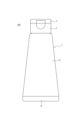
図1は、本開示の一実施形態であるチューブ容器100の構成を示す正面図である。チューブ容器100は、内容物の収容空間S(図2参照)を形成する容器本体1と、容器本体1の口部42(図2参照)に装着される注出キャップ2と、注出キャップ2の注出孔を閉塞する蓋体3とを備えている。なお、本明細書、特許請求の範囲、要約書および図面では、蓋体3が位置する側を上方(図1における上側)とし、容器本体1が位置する側を下方(図1における下側)とする。また、容器本体1の層構成の説明においては、収容空間S側を内側とし、容器本体1の外周面側を外側とする。
Figure 1 is a front view showing the configuration of a
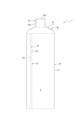
まず、容器本体1について説明する。容器本体1は、図1に示すように、内容物の収容空間S(図2参照)を形成し、押圧することで内容物を注出する胴部1aと、胴部1aの下端を閉塞する底部1bとを備えている。容器本体1の製造方法としては、例えば図2に示すように内容物の収容空間Sを形成するチューブ体30とヘッド40を組み合わせて形成することができる。ヘッド40には、上方に向けて開口し注出キャップ2を装着する口部42が形成されている。
First, the
チューブ体30は、例えば、帯状に成形された積層構造を有するラミネートシート31を、その両側端31a,31bを突き合わせ部32において突き合わせるようにして丸め、当該突き合わせ部32において高周波シールやヒートシール等の手段によって溶着することによって略円筒状に形成することができる。本実施形態において、チューブ体30は略円筒状とされているが、略筒状であれば、例えば略楕円筒状とすることもできる。
The
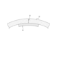
また、ラミネートシート31の突き合わせ部32の接合を補強するために、図2及び図3に示すように、チューブ体30の内面には、突き合わせ部32に沿って補強テープ35が設けられている。
In addition, to reinforce the joint at the
ヘッド40は、本実施形態では、円錐台形状に形成された肩部41を有している。ヘッド40は、例えば肩部41の外周縁がチューブ体30の上端の内周面に全周に亘って溶着されることで、チューブ体30に一体に連ねて設けることができる。ヘッド40は、また、上述のチューブ体30をヘッド40の材料と共に金型に装着し、圧縮成形を行うことによってチューブ体30と一体形成することもできる。
In this embodiment, the
肩部41の中心部分には、円筒状の口部42が上方に向かって突出して設けられている。口部42の先端は、内容物の収容空間Sに通じる開口42aとなっている。口部42の外周面には、口部42に注出キャップ2を装着するための環状突部42bが設けられている。
A
このような略円筒形を有するチューブ体30の下部の開放端を通して内容物を収容空間S内に充填した後、当該開放端を高周波シールやヒートシール等の手段により閉塞して底部1bを形成することによって容器本体1を構成することができる。
The contents are filled into the storage space S through the open end at the bottom of the
本実施形態において、容器本体1の胴部1aを構成するチューブ体30のラミネートシート31は、図4に示す層構成を有している。すなわち、容器本体1のラミネートシート31は、収容空間S側である内側より順に、内側ポリエチレン系樹脂層11、ドライラミネート(DL)接着層23、ポリエチレンテレフタレート(PET)フィルム層13、押出ポリエチレン(PE)層14、ポリエチレン(PE)フィルムによるポリオレフィン樹脂層15、押出ポリエチレン(PE)層16、バリア層としてのアルミニウム(AL)箔17、ドライラミネート(DL)接着層25、PETフィルムの外側にグラビア印刷を施し、内側にアルミニウムを蒸着した高反射層19、ドライラミネート接着層27、外側ポリエチレン系樹脂層21、ドライラミネート接着層29、及び高硬度保護層18を備えている。なお、容器本体1における胴部1a以外の部位は、胴部1aと同一の層構成を有していてもよいし、一部の層を省略したり、一部の層を付加した構成であってもよい。
In this embodiment, the
アルミニウム箔17は、遮光性、酸素バリア性及び水蒸気バリア性を備えたバリア層として機能する。アルミニウム箔17の厚みは、必要な遮光性、酸素バリア性及び水蒸気バリア性を確保しつつ、胴部1aの可撓性及び復元性等を確保し得る観点から7μm~20μmの範囲であることが好ましい。本実施形態では、アルミニウム箔17の厚みは約12μmである。なお、バリア層として、アルミニウム以外の金属箔(例えば、金箔、銀箔、白金箔、銅箔、チタン箔、錫箔など)を用いるように構成してもよい。
The
高反射層19は、ポリエチレンテレフタレート(PET)フィルム製のベース材の一方の面(内側面)にアルミニウム蒸着膜が形成され、他方の面(外側面)に装飾のためのグラビア印刷が施されている。本実施形態において、アルミニウム蒸着膜は、表面粗さが小さいベース材の片面に形成されるため同様に表面粗さが小さく入射光の散乱が少ないことから、薄肉でありながら高い光反射率(光沢度)を得ることができる。本実施形態では、ベース材の厚みは約12μmであり、アルミニウム蒸着膜の厚みは約100nmである。アルミニウム蒸着膜の厚みは、高反射率(光沢度)を得るために、50nm以上であることが好ましい。なお、アルミニウム蒸着膜に代えて、金、銀、白金、亜鉛、ニッケル等の他の金属蒸着膜を形成するように構成してもよい。
The highly
本実施形態では、ベース材の外側面にグラビア印刷を施すと共に、内側面にアルミニウム蒸着膜を施すことで容器本体1の装飾性と光沢性及び光輝性とを両立させている。出願人が鋭意検討した結果、アルミニウム蒸着膜の上に更にグラビア印刷を施すと、アルミニウム蒸着膜がグラビア印刷に用いる有機溶剤によって劣化し所望の反射率が得られない場合があった。従って、アルミニウム蒸着膜とグラビア印刷による装飾は、ベース材の異なる面に形成する必要がある。また、アルミニウム蒸着膜をベース材の外側に形成すると、ベース材の内側に形成したグラビア印刷による装飾の視認性が低下する。以上の理由により、高反射層19は、ベース材の外側にグラビア印刷による装飾を施し、ベース材の内側にアルミニウム蒸着膜を形成する構成としている。なお、ベース材には、ポリエチレンテレフタレート(PET)フィルム以外の各種樹脂製フィルムを用いてもよく、金属蒸着膜の表面粗さを小さく抑えることができればよい。金属蒸着膜の表面粗さは、金属箔の表面粗さよりも小さいことが好ましい。
In this embodiment, the
本実施形態では、高反射層19は、図4に示すように、ドライラミネート(DL)接着層25によりアルミニウム箔17の外側面と接着されている。ドライラミネート接着層25は、積層前の一方のフィルムに接着剤を塗布し乾燥させた後に、もう一方のフィルムに圧着により貼り合わせるための接着層である。
In this embodiment, as shown in FIG. 4, the highly
外側ポリエチレン系樹脂層21は、本実施形態では、柔軟性、透明性及びシール性を備えた直鎖状低密度ポリエチレン(LLDPE)によって構成されている。外側ポリエチレン系樹脂層21に用いるポリエチレンには、LLDPEの他、例えば低密度ポリエチレン(LDPE)、又は高密度ポリエチレン樹脂(HDPE)等の各種ポリエチレン系樹脂を用いることができる。本実施形態において、外側ポリエチレン系樹脂層21の厚みは約60μmである。後述するように、外側ポリエチレン系樹脂層21の厚みを高硬度保護層18の厚みよりも厚く構成することによって、ラミネートシート31の両側端31a,31b(図3参照)を突き合わせて高周波シール又はヒートシールする際に、この外側ポリエチレン系樹脂層21の両側端同士を所定の強度で溶着することができる。従って、高硬度保護層18の融点が高いこと等に起因して高硬度保護層18の両側端同士が十分な強度でシールされない場合でも、外側ポリエチレン系樹脂層21の部分で溶着強度を確保することができるので、突き合わせ部32において両側端31a,31b同士の溶着が剥がれて突き合わせ部32が屈曲してしまう等の不具合を抑制することができる。なお、外側ポリエチレン系樹脂層21は、ドライラミネート接着層27によって、高反射層19の外側面に接着されている。
In this embodiment, the outer
高硬度保護層18は、本実施形態においてラミネートシート31の最外層を構成し、容器本体1の外表面に傷等が発生しにくいように、高硬度を有するポリエチレンテレフタレート(PET)フィルムによって形成されている。本実施形態において、高硬度保護層18の厚みは約12μmである。本実施形態において高硬度保護層18として用いられるPETフィルムは、JIS K 5600-5-4で定められる、引っかき硬度(鉛筆法)測定によって得られた鉛筆硬度が「H」である。なお、出願人が鋭意検討した結果、高硬度保護層18の鉛筆硬度が「3B」、又は「3B」より硬ければ、後述する耐摩耗試験において基準以上の傷が発生しないという結果が得られている。高硬度保護層18は、ドライラミネート接着層29によって、外側ポリエチレン系樹脂層21の外側面に接着されている。
In this embodiment, the high-hardness
なお、上述のラミネートシート31の両側端31a,31bを突き合わせて良好に高周波シール又はヒートシールするためには、高硬度保護層18の厚みを16μm以下とすることが好ましく、外側ポリエチレン系樹脂層21の厚みを30μm以上とすることが好ましい。
In order to butt both side ends 31a, 31b of the
内側ポリエチレン系樹脂層11は、本実施形態においてラミネートシート31の最内層を構成し、外側ポリエチレン系樹脂層21と同様に柔軟性、透明性及びシール性を備えた直鎖状低密度ポリエチレン(LLDPE)によって構成されている。本実施形態において、内側ポリエチレン系樹脂層11の厚みは約80μmである。このように、ラミネートシート31の最内層に融点が低いポリエチレン系樹脂を用いているので、チューブ体30の下部の開放端を高周波シール又はヒートシール等の手段により容易に閉塞して底部1bを形成することができる。なお、内側ポリエチレン系樹脂層11についても、外側ポリエチレン系樹脂層21と同様に、LLDPEの他、例えば低密度ポリエチレン(LDPE)、又は高密度ポリエチレン樹脂(HDPE)等の各種ポリエチレン系樹脂を用いることができる。
The inner polyethylene resin layer 11 constitutes the innermost layer of the
内側ポリエチレン系樹脂層11の外側面には、ドライラミネート接着層23を介して、PETフィルム層13が接着されている。本実施形態では、PETフィルム層13の厚みは約12μmである。
A
上述の内側ポリエチレン系樹脂層11とPETフィルム層13の積層体は、PETフィルム層13の外側面に接着強度を高めるためのアンカーコート(AC)層13aを塗布し、押出ポリエチレン層14を接着層としてポリオレフィン樹脂層15と接着される。本実施形態では、押出ポリエチレン層14の厚みは約30μmである。
The laminate of the inner polyethylene resin layer 11 and the
ポリオレフィン樹脂層15は、本実施形態ではポリエチレン(PE)で形成されたフィルム部材である。ポリオレフィン樹脂層15に用いるポリエチレンには、例えば低密度ポリエチレン(LDPE)、直鎖状低密度ポリエチレン(LLDPE)又は高密度ポリエチレン樹脂(HDPE)を用いることができる。特にLLDPEを用いた場合には、容器本体1の胴部1aに高いスクイズ性を付与することができる。ポリオレフィン樹脂層15の厚みは、容器本体1の胴部1aの可撓性及び復元性等を確保し得る観点から60μm~200μmの範囲であることが好ましい。本実施形態では、ポリオレフィン樹脂層15の厚みは約100μmである。このように、ポリオレフィン樹脂層15の厚みをバリア層及び高反射層19の厚みよりも大きく形成することで、胴部1aの復元性を確保することができる。なお、ポリオレフィン樹脂層15の構成は上記態様には限定されず、ポリエチレン以外のポリオレフィン樹脂であるポリプロピレン等を用いてもよい。また、ポリオレフィン樹脂以外の各種樹脂を用いてもよい。
In this embodiment, the
アルミニウム箔17、高反射層19、外側ポリエチレン系樹脂層21、及び高硬度保護層18の積層体には、アルミニウム箔17の内側面にAC層17aが塗布される。そして、押出ポリエチレン層16を接着層として、内側ポリエチレン系樹脂層11、PETフィルム層13及びポリオレフィン樹脂層15の積層体と接着される。本実施形態では、押出ポリエチレン層16の厚みは約30μmである。
The laminate of the
次に、補強テープ35について説明する。補強テープ35は、図2及び図3に示すように、チューブ体30の内面において、突き合わせ部32に沿って上下方向に帯状に延びる態様で設けられている。本実施形態の補強テープ35は、図5に示す層構成を有している。すなわち、補強テープ35は、収容空間S側である内側より順に、内側補強樹脂層51、ドライラミネート(DL)接着層61、ポリエチレンテレフタレート(PET)フィルム層53、ドライラミネート(DL)接着層63、アルミニウム(AL)箔55、押出ポリエチレン(PE)層57、及び外側補強樹脂層59を備えている。
Next, the reinforcing
内側補強樹脂層51は、本実施形態では直鎖状低密度ポリエチレン(LLDPE)によって構成されている。内側補強樹脂層51には、LLDPEの他、例えば低密度ポリエチレン(LDPE)、又は高密度ポリエチレン樹脂(HDPE)等の各種ポリエチレン系樹脂を用いることができる。本実施形態において、内側補強樹脂層51の厚みは約80μmである。
In this embodiment, the inner reinforcing
内側補強樹脂層51の外側面には、ドライラミネート接着層61を介して、PETフィルム層53が接着されている。このように、補強テープ35にPETフィルム層53を設けるようにしたので、補強テープ35の強度を高めて、突き合わせ部32における両側端31a,31bの接合をより確実に補強することができる。本実施形態では、PETフィルム層53の厚みは約12μmである。
A
PETフィルム層53の外側面には、ドライラミネート接着層63を介して、アルミニウム(AL)箔55が接着されている。アルミニウム箔55は、遮光性、酸素バリア性及び水蒸気バリア性を備えたバリア層として機能する。すなわち、突き合わせ部32における両側端31a,31bの接合が剥がれた場合であっても、容器本体1の収容空間Sに収容されている内容物が、光、酸素、水蒸気等に触れることによる劣化や変質を生じることを抑制することができる。アルミニウム箔55の厚みは、必要な遮光性、酸素バリア性及び水蒸気バリア性を確保しつつ、胴部1aの可撓性を適切に維持する観点から7μm~20μmの範囲であることが好ましい。本実施形態では、アルミニウム箔55の厚みは約12μmである。なお、バリア層として、アルミニウム以外の金属箔(例えば、金箔、銀箔、白金箔、銅箔、チタン箔、錫箔など)を用いるように構成してもよい。
An aluminum (AL)
アルミニウム箔55の外側面には、接着強度を高めるためのアンカーコート(AC)層65が塗布され、押出ポリエチレン層57を接着層として外側補強樹脂層59と接着される。本実施形態では、押出ポリエチレン層57の厚みは約30μmである。
The outer surface of the
外側補強樹脂層59は、本実施形態では直鎖状低密度ポリエチレン(LLDPE)によって構成されている。外側補強樹脂層59には、LLDPEの他、例えば低密度ポリエチレン(LDPE)、又は高密度ポリエチレン樹脂(HDPE)等の各種ポリエチレン系樹脂を用いることができる。本実施形態において、外側補強樹脂層59の厚みは約60μmであり、白色に着色されている。
In this embodiment, the outer reinforcing
図2に示すように、本実施形態の補強テープ35は、突き合わせ部32に沿ってチューブ体30のヘッド40と連接される一端から閉塞されて底部1bを形成する他端まで延びており、突き合わせ部32の長手方向の全範囲において両側端31a,31bを跨いでチューブ体30の内面に貼り付けられている。このような構成によって、ラミネートシート31の突き合わせ部32の接合が補強テープ35により補強されると共に、当該突き合わせ部32において両側端31a,31bの接合が剥がれたとしても、当該部分を補強テープ35により繋いだ状態に保持して、当該部分から内容物が漏れ出すことを抑制することができる。
2, the reinforcing
上述の補強テープ35は、図6に示すような補強テープ35の供給装置70を用いてラミネートシート31に供給することができる。供給装置70は、予め図5に示す積層構造を有する補強テープ35を供給するロール72を有し、このロール72から供給される補強テープ35を案内ローラ74と案内ローラ75とを通してラミネートシート31の内側に向けて供給する。
The above-mentioned reinforcing
上述の供給装置70を用いて、ラミネートシート31の内面に供給された補強テープ35は、例えば図示しない成型装置により所定温度にまで加熱されつつラミネートシート31の内面に向けて押し付けられて、両側端31a,31bの突き合わせ部32に溶着される。このとき、補強テープ35は、図5に示すように、外側補強樹脂層59及び内側補強樹脂層51の厚みが他のいずれの中間層の厚みよりも厚く形成されているため、外側補強樹脂層59及び内側補強樹脂層51の一部が他の中間層よりも側方(図3の周方向)に向けて押し出され、外側補強樹脂層59及び内側補強樹脂層51の当該押し出された部分が互いに溶着して他の中間層の周方向端部を覆うと共にラミネートシート31の内面に溶着される。これによって、図5に示すアルミニウム箔55等の周方向端部が外側補強樹脂層59及び内側補強樹脂層51によって覆われるため、アルミニウム箔55等が収容空間Sから隔離されることになる。従って、収容空間S内の内容物がアルミニウム箔55等に直接触れることを抑制することができるので、当該内容物の変色等による品質低下を抑制することができる。補強テープ35が溶着されたラミネートシート31は、長手方向に裁断されてチューブ体30が形成される。
The reinforcing
また、本実施形態では、外側補強樹脂層59を白色に着色し、他の層(内側補強樹脂層51やアルミニウム箔55)とは異なる色になるようにしている。このような構成によって、補強テープ35の構成層のうち、ラミネートシート31の内周面に対向する外側補強樹脂層59を、内側補強樹脂層51やアルミニウム箔55などの他の層とは異なる色とすることができる。従って、補強テープ35が設けられたラミネートシート31を内側から目視し、外側補強樹脂層59の側方(周方向)へのはみ出し具合を確認することによって、アルミニウム箔55等の側方が外側補強樹脂層59等によって十分に覆われているか否かを容易に確認することができる。
In addition, in this embodiment, the outer reinforcing
次に、注出キャップ2について説明する。注出キャップ2は、容器本体1の収容空間S内の内容物を外部に注出するための注出孔を備えており、容器本体1の口部42の環状突部42bにアンダーカット係合により装着されている。また、注出キャップ2の上方には、注出孔を覆う蓋体3が設けられている。蓋体3は、図示しないヒンジによって注出キャップ2と一体的に形成されており、蓋体3をヒンジ周りに回動させることで、注出孔を開放したり、蓋体3で注出孔を閉塞することができる。なお、注出キャップ2の容器本体1への装着は、上述のアンダーカット係合に限定されず、容器本体1の口部42に形成された雄ねじ部に注出キャップ2をねじ係合させる等によって装着するように構成してもよい。
Next, the pouring
上記のように構成されるチューブ容器100から内容物を注出するにあたっては、蓋体3をヒンジ周りに回動させて注出孔を開放状態とした後、注出孔が塗布領域に対向するようにチューブ容器100を姿勢変更して、胴部1aを押圧(スクイズ)する。これにより、容器本体1の収容空間S内の圧力が高まり、内容物が注出孔から外部に注出される。
When pouring the contents from the
所要量の内容物を注出した後は、胴部1aへの押圧を解除する。これによって収容空間S内の圧力が外気圧へと戻り、容器本体1の胴部1aは、それ自身の復元力により元の形状へと戻る。容器本体1の胴部1aを構成するチューブ体30のラミネートシート31は、バリア層としてのアルミニウム箔17、並びに光沢性及び光輝性向上のための高反射層19よりも厚みが大きなポリオレフィン樹脂層15を有している。そのため、胴部1aの押圧の解除に伴い、その材料特性に起因した変形に対する優れた復元性により胴部1aは押圧前の元の形状へと戻る。
After the required amount of contents has been dispensed, the pressure on the
以上述べたように、本実施形態に係るチューブ容器100は、内容物の収容空間Sを形成するチューブ体30が複数材料による積層構造を有するチューブ容器100であって、チューブ体30は、シートの両側端31a,31bを突き合わせた筒状のラミネートシート31と、ラミネートシート31の内側面に、突き合わせ部32に沿って設けられた補強テープ部(補強テープ35)とを有し、ラミネートシート31は、最外層を形成する高硬度保護層18と、高硬度保護層18の内側に形成される外側ポリエチレン系樹脂層21と、最内層を形成する内側ポリエチレン系樹脂層11とを有し、高硬度保護層18は、鉛筆硬度が3B又は3Bより硬く、補強テープ部(補強テープ35)は、ラミネートシート31の内側面に当接する最外層がポリエチレン系樹脂層(外側補強樹脂層59)であるように構成した。このような構成の採用によって、チューブ容器100の容器本体1の最外層に所定の硬度を有する高硬度保護層18が形成されるので、チューブ容器100の表面への傷の発生を抑制することが可能となる。
As described above, the
なお、本実施形態では、ラミネートシート31の最内層、及び補強テープ35の最内層をいずれもポリエチレン系樹脂層としているので、チューブ体30の下部の開放端を高周波シールやヒートシール等の手段により閉塞して底部1bを形成する際に、補強テープ35部分も含めて容易にシールすることができる。同様に、チューブ体30の上端をヘッド40に溶着する場合にも、肩部41の外周縁をチューブ体30の上端の内周面に全周に亘って容易に溶着することができる。
In this embodiment, the innermost layer of the
また、本実施形態では、高硬度保護層18がポリエチレンテレフタレートを含むように構成した。このような構成の採用によって、チューブ容器100の最外層をなす高硬度保護層18として所定の硬度を有するポリエチレンテレフタレートを適用することでチューブ容器100の表面への傷の発生を効果的に抑制することが可能となる。
In addition, in this embodiment, the high-hardness
また、本実施形態では、外側ポリエチレン系樹脂層21の厚みが、高硬度保護層18の厚みよりも大きくなるように構成した。このような構成の採用によって、ラミネートシート31の両側端31a,31bを突き合わせて高周波シール又はヒートシールする際に、比較的融点が低い外側ポリエチレン系樹脂層21の両側端同士を所定の強度で溶着することができる。従って、高硬度保護層18の融点が高いこと等に起因して高硬度保護層18の両側端同士が十分な強度でシールされない場合でも、外側ポリエチレン系樹脂層21の部分で溶着強度を確保することができるので、突き合わせ部32において両側端31a,31b同士の溶着が剥がれて突き合わせ部32が屈曲してしまう等の不具合を抑制することができる。
In this embodiment, the thickness of the outer
また、本実施形態では、外側ポリエチレン系樹脂層21の厚みは30μm以上であり、高硬度保護層18の厚みは16μm以下であるように構成した。このような構成の採用によって、高硬度保護層18の両側端同士が十分な強度でシールされない場合でも、外側ポリエチレン系樹脂層21の部分で溶着強度を確保することができるので、突き合わせ部32において両側端31a,31b同士の溶着が剥がれて突き合わせ部32が屈曲してしまう等の不具合を抑制することができる。
In this embodiment, the thickness of the outer
また、本実施形態では、補強テープ部(補強テープ35)の最外層及び最内層は、他のいずれの中間層よりも厚みが厚く形成されるように構成した。このような構成の採用によって、アルミニウム箔55等の中間層の周方向端部が外側補強樹脂層59及び内側補強樹脂層51によって覆われるため、収容空間S内の内容物がアルミニウム箔55等に直接触れることを抑制でき、当該内容物の変色等による品質低下を抑制することができる。
In addition, in this embodiment, the outermost and innermost layers of the reinforcing tape portion (reinforcing tape 35) are configured to be thicker than any of the other intermediate layers. By adopting such a configuration, the circumferential ends of the intermediate layers such as the
また、本実施形態では、補強テープ部(補強テープ35)の最外層は、補強テープ部の他の構成層とは異なる色を有するように構成した。このような構成の採用によって、補強テープ35をラミネートシート31の内面に高周波シール又はヒートシールする際に、外側補強樹脂層59の側方(周方向)へのはみ出し具合を確認することによって、アルミニウム箔55等の側方が外側補強樹脂層59によって十分に覆われているか否かを容易に確認することができる。
In addition, in this embodiment, the outermost layer of the reinforcing tape portion (reinforcing tape 35) is configured to have a color different from the other constituent layers of the reinforcing tape portion. By adopting such a configuration, when the reinforcing
また、本実施形態では、ラミネートシート31及び補強テープ部(補強テープ35)は、金属箔を有するバリア層を備えるように構成した。このような構成の採用によって、突き合わせ部32における両側端31a,31bの接合が剥がれた場合であっても、補強テープ35が有する金属箔(アルミニウム箔55)によって光、酸素、水蒸気等の透過を抑制することができるので、容器本体1の収容空間Sに収容されている内容物が、光、酸素、水蒸気等に触れることによる劣化や変質を生じることを抑制することができる。
In addition, in this embodiment, the
本開示を諸図面や実施例に基づき説明してきたが、当業者であれば本開示に基づき種々の変形や修正を行うことが容易であることに注意されたい。従って、これらの変形や修正は本発明の範囲に含まれることに留意されたい。例えば、各構成部に含まれる機能などは論理的に矛盾しないように再配置可能であり、複数の構成部を1つに組み合わせたり、或いは分割したりすることが可能である。本発明の範囲にはこれらも包含されるものと理解されたい。 Although the present disclosure has been described based on various drawings and examples, it should be noted that a person skilled in the art would be able to easily make various modifications and corrections based on the present disclosure. Therefore, it should be noted that these modifications and corrections are included in the scope of the present invention. For example, the functions contained in each component can be rearranged so as not to cause logical inconsistencies, and multiple components can be combined into one or divided. It should be understood that these are also included in the scope of the present invention.
例えば、本実施形態では、高硬度保護層18として、ポリエチレンテレフタレート(PET)フィルムを用いるように構成したが、この態様には限定されない。高硬度保護層18として、PETフィルム以外の所定の硬度を有するフィルムを用いてもよい。
For example, in this embodiment, a polyethylene terephthalate (PET) film is used as the high-hardness
また、本実施形態では、外側ポリエチレン系樹脂層21の厚みが、高硬度保護層18の厚みよりも大きくなるように構成したが、この態様には限定されない。補強テープ35による補強によって、ラミネートシート31の突き合わせ部32から内容物が漏れ出すのを抑止可能であればよい。
In addition, in this embodiment, the thickness of the outer
また、本実施形態では、補強テープ35の最外層及び最内層は、他のいずれの中間層よりも厚みが厚く形成されるように構成したが、この態様には限定されない。他の手段によって中間層が内容物に触れないように構成してもよいし、内容物によっては必ずしも中間層が内容物に触れないように構成する必要はない。
In addition, in this embodiment, the outermost and innermost layers of the reinforcing
また、本実施形態では、補強テープ35の外側補強樹脂層59を白色に着色するように構成したが、この態様には限定されない。外側補強樹脂層59は、補強テープ35の他の層とは異なる白色以外の色に着色されていてもよい。また、外側補強樹脂層59は、着色されていなくてもよい。
In addition, in this embodiment, the outer reinforcing
また、本実施形態では、ラミネートシート31及び補強テープ35は、アルミニウム箔17,55を有するバリア層を備えるように構成したが、この態様には限定されない。ラミネートシート31のみがバリア層を備えるように構成してもよいし、内容物によってはラミネートシート31及び補強テープ35のいずれもがバリア層を有していなくてもよい。
In addition, in this embodiment, the
また、本実施形態では、高反射層19は、ベース材の外側面にグラビア印刷による装飾を施すと共に内側面にアルミニウム蒸着膜を形成するように構成したが、この態様には限定されない。ベース材の外側面に印刷による装飾を施さなくてもよく、その場合アルミニウム蒸着膜は、ベース材の外側面に形成してもよい。また、アルミニウム蒸着膜をベース材の両面に形成してもよい。また、ラミネートシート31は高反射層19を備えていなくてもよい。
In addition, in this embodiment, the highly
また、グラビア印刷は、高硬度保護層18の内側面に施してもよい。
Gravure printing may also be applied to the inner surface of the high-hardness
(硬度と耐摩耗性)
次に、図1に示すチューブ容器100の胴部1aを構成するチューブ体30のラミネートシート31の層構成について、図4に示す層構成(実施例1)と、図4から外側の高硬度保護層18及びドライラミネート(DL)接着層29を除いた層構成(比較例1)を用意し、各層構成について、鉛筆硬度の測定と耐摩耗試験を行った。
(Hardness and wear resistance)
Next, for the layer structure of the
表1は、実施例1と比較例1のそれぞれについて、鉛筆硬度の測定、及び耐摩耗試験を行った結果をまとめたものである。鉛筆硬度の測定は、JIS K 5600-5-4で定められる、引っかき硬度(鉛筆法)測定によるものである。また、耐摩耗試験は、濾紙とラミネートシートの最外層との間に1.8kgfの荷重を加えながら100回往復運動させて、ラミネートシートの最外層に基準以上の傷が発生したか否かを評価した。 Table 1 shows the results of pencil hardness measurements and abrasion resistance tests for Example 1 and Comparative Example 1. Pencil hardness measurements were made according to the scratch hardness (pencil method) measurement method defined in JIS K 5600-5-4. The abrasion resistance test involved applying a load of 1.8 kgf between the filter paper and the outermost layer of the laminate sheet and reciprocating 100 times to evaluate whether scratches greater than the standard occurred on the outermost layer of the laminate sheet.

表1の耐摩耗試験において、「良」は、基準以上の傷が発生しないことを意味し、「否」は、基準以上の傷が発生することを意味するものとする。 In the abrasion resistance test in Table 1, "good" means that no scratches greater than the standard occurred, and "bad" means that scratches greater than the standard occurred.
鉛筆硬度については、実施例1で「H」の鉛筆硬度が得られたのに対して、比較例1では「6B未満」という結果になった。また、耐摩耗試験については、実施例1で基準以上の傷が発生しなかったのに対して、比較例1では、基準以上の傷の発生が認められた。なお、出願人が鉛筆硬度ごとに耐摩耗試験を実施したところ、鉛筆硬度が「3B」以上であれば、基準以上の傷が発生しないことを確認することができた。 With regard to pencil hardness, Example 1 achieved a pencil hardness of "H," while Comparative Example 1 achieved a result of "less than 6B." In addition, with regard to the abrasion resistance test, Example 1 did not produce scratches greater than the standard, whereas Comparative Example 1 confirmed the production of scratches greater than the standard. When the applicant carried out abrasion resistance tests for each pencil hardness, it was confirmed that scratches greater than the standard did not occur if the pencil hardness was "3B" or greater.
(高硬度保護層の厚みと突き合わせ部の接合強度)
次に、高硬度保護層18及び外側ポリエチレン系樹脂層21の厚みと、突き合わせ部32の接合強度との関係について評価を行った。結果を表2に示す。
(Thickness of high-hardness protective layer and bonding strength of butted joint)
Next, an evaluation was conducted on the relationship between the thickness of the high-hardness
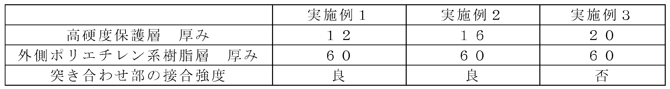
表2によれば、高硬度保護層18の厚みが12μm(実施例1)、又は16μm(実施例2)では、突き合わせ部32の接合強度が良好であり、突き合わせ部32の剥離等の不具合は見られなかった。一方、高硬度保護層18の厚みが20μm(実施例3)では、突き合わせ部32の剥離が認められた。これは、実施例1,2では、外側ポリエチレン系樹脂層21の厚み(60μm)が、高硬度保護層18の厚み(12μm又は16μm)よりも十分に大きいため、高硬度保護層18における接合強度が十分ではなくても、外側ポリエチレン系樹脂層21部分の接合によって突き合わせ部32全体の接合強度が良好な状態に維持されていたものと考えられる。これに対して、実施例3では、外側ポリエチレン系樹脂層21の厚み(60μm)と、高硬度保護層18の厚み(20μm)との差が小さくなっているため、高硬度保護層18における接合強度が十分ではない場合に、外側ポリエチレン系樹脂層21部分の接合によって突き合わせ部32全体の接合強度を良好な状態に維持することができなくなっていると考えられる。なお、外側ポリエチレン系樹脂層21の厚みについても、30μm以上であることが望ましいという結果が得られた。
According to Table 2, when the thickness of the high-hardness
本開示によれば、容器表面への傷の発生を抑制することが可能なチューブ容器100を提案することが可能となる。
This disclosure makes it possible to propose a
1 容器本体
1a 胴部
1b 底部
2 注出キャップ
3 蓋体
11 内側ポリエチレン系樹脂層
13 ポリエチレンテレフタレート(PET)フィルム層
13a アンカーコート(AC)層
14 押出ポリエチレン(PE)層
15 ポリオレフィン樹脂層
16 押出ポリエチレン(PE)層
17 アルミニウム箔(金属箔)
17a アンカーコート(AC)層
18 高硬度保護層
19 高反射層
21 外側ポリエチレン系樹脂層
23 ドライラミネート接着層
25 ドライラミネート接着層
27 ドライラミネート接着層
29 ドライラミネート接着層
30 チューブ体
31 ラミネートシート
31a,31b 側端
32 突き合わせ部
35 補強テープ(補強テープ部)
40 ヘッド
41 肩部
42 口部
42a 開口
42b 環状突部
51 内側補強樹脂層
53 ポリエチレンテレフタレート(PET)フィルム層
55 アルミニウム箔(金属箔)
57 押出ポリエチレン(PE)層
59 外側補強樹脂層(ポリエチレン系樹脂層)
61 ドライラミネート接着層
63 ドライラミネート接着層
65 アンカーコート(AC)層
70 供給装置
72 ロール
74 案内ローラ
75 案内ローラ
100 チューブ容器
S 収容空間
REFERENCE SIGNS
17a Anchor coat (AC)
40
57 Extruded polyethylene (PE)
61 Dry laminate
Claims (6)
前記チューブ体は、
シートの両側端を突き合わせた筒状のラミネートシートと、
該ラミネートシートの内側面に、突き合わせ部に沿って設けられた補強テープ部とを有し、
前記ラミネートシートは、最外層を形成する高硬度保護層と、該高硬度保護層の内側に形成される外側ポリエチレン系樹脂層と、該外側ポリエチレン系樹脂層の内側に形成され内側面に蒸着膜を有すると共に外側面に印刷が施された高反射層と、該高反射層の内側に形成され金属箔を有するバリア層と、最内層を形成する内側ポリエチレン系樹脂層とを有し、前記高硬度保護層は、鉛筆硬度が3B又は3Bより硬くポリエチレンテレフタレートを含み、
前記補強テープ部は、前記ラミネートシートの内側面に当接する最外層がポリエチレン系樹脂層であることを特徴とするチューブ容器。 A tube container having a tube body forming a storage space for contents, the tube body having a laminated structure made of multiple materials,
The tube body is
A cylindrical laminate sheet with both ends of the sheet butted together;
A reinforcing tape portion is provided along the butted portion on the inner surface of the laminate sheet,
The laminate sheet has a high-hardness protective layer forming an outermost layer, an outer polyethylene-based resin layer formed inside the high-hardness protective layer, a highly reflective layer formed inside the outer polyethylene-based resin layer and having a vapor-deposited film on its inner surface and printed on its outer surface, a barrier layer formed inside the highly reflective layer and having a metal foil, and an inner polyethylene-based resin layer forming an innermost layer, the high-hardness protective layer having a pencil hardness of 3B or harder than 3B and containing polyethylene terephthalate,
The tube container is characterized in that the reinforcing tape portion has an outermost layer that abuts against the inner surface of the laminate sheet and is a polyethylene-based resin layer.
Priority Applications (4)
| Application Number | Priority Date | Filing Date | Title |
|---|---|---|---|
| JP2018161743A JP7653757B2 (en) | 2018-08-30 | 2018-08-30 | Tube container |
| PCT/JP2019/024237 WO2020044741A1 (en) | 2018-08-30 | 2019-06-19 | Tube container |
| US17/271,120 US11542066B2 (en) | 2018-08-30 | 2019-06-19 | Tube container |
| EP19855198.8A EP3845469A4 (en) | 2018-08-30 | 2019-06-19 | Tube container |
Applications Claiming Priority (1)
| Application Number | Priority Date | Filing Date | Title |
|---|---|---|---|
| JP2018161743A JP7653757B2 (en) | 2018-08-30 | 2018-08-30 | Tube container |
Publications (2)
| Publication Number | Publication Date |
|---|---|
| JP2020033060A JP2020033060A (en) | 2020-03-05 |
| JP7653757B2 true JP7653757B2 (en) | 2025-03-31 |
Family
ID=69644178
Family Applications (1)
| Application Number | Title | Priority Date | Filing Date |
|---|---|---|---|
| JP2018161743A Active JP7653757B2 (en) | 2018-08-30 | 2018-08-30 | Tube container |
Country Status (4)
| Country | Link |
|---|---|
| US (1) | US11542066B2 (en) |
| EP (1) | EP3845469A4 (en) |
| JP (1) | JP7653757B2 (en) |
| WO (1) | WO2020044741A1 (en) |
Citations (5)
| Publication number | Priority date | Publication date | Assignee | Title |
|---|---|---|---|---|
| JP2010235160A (en) | 2009-03-31 | 2010-10-21 | Dainippon Printing Co Ltd | Laminated tube |
| WO2011083499A2 (en) | 2010-01-11 | 2011-07-14 | Ashok Chaturvedi | Flexible overlap sealed laminate tube, laminates, and method for forming tube from laminates |
| JP2011232388A (en) | 2010-04-23 | 2011-11-17 | Shin Etsu Chem Co Ltd | Pellicle storage container |
| JP2017114507A (en) | 2015-12-24 | 2017-06-29 | 大日本印刷株式会社 | Laminate and tube container |
| CN206750531U (en) | 2017-03-20 | 2017-12-15 | 林志弘 | Bottle class buffer packing bag |
Family Cites Families (12)
| Publication number | Priority date | Publication date | Assignee | Title |
|---|---|---|---|---|
| DE3445815A1 (en) * | 1983-12-30 | 1985-07-11 | Colgate-Palmolive Co., New York, N.Y. | LAMINATE FILM AND COMPRESSIBLE DISPENSER MADE FROM IT |
| US4595612A (en) * | 1983-12-30 | 1986-06-17 | Colgate-Palmolive Company | Laminated polyester containing substrate and collapsible dispensing container made therefrom |
| SE445031B (en) * | 1984-10-02 | 1986-05-26 | Akerlund & Rausing Ab | PACKAGING TUBES AND PROCEDURES AND DEVICES FOR MANUFACTURING THEREOF |
| JP3484542B2 (en) * | 1992-11-30 | 2004-01-06 | 大日本印刷株式会社 | Tube container body |
| JP3756200B2 (en) * | 1993-07-28 | 2006-03-15 | 大日本印刷株式会社 | Tube container body |
| JPH08104340A (en) * | 1993-11-08 | 1996-04-23 | Toppan Printing Co Ltd | Laminated tube container |
| JP3893650B2 (en) * | 1996-11-06 | 2007-03-14 | 東洋製罐株式会社 | Cyclic olefin copolymer container with excellent scratch resistance |
| JPH11254595A (en) * | 1998-03-11 | 1999-09-21 | Toppan Printing Co Ltd | Packaging material and packaging container using this packaging material |
| JP2007030424A (en) * | 2005-07-28 | 2007-02-08 | Mitsubishi Plastics Ind Ltd | Laminated sheet for packaging body and packaging body formed by this sheet |
| JP5412963B2 (en) * | 2009-06-03 | 2014-02-12 | 凸版印刷株式会社 | Laminated packaging bags |
| EP2674368A1 (en) | 2012-06-15 | 2013-12-18 | Aisapack Holding SA | Butt-welded tubular packaging body |
| JP6907458B2 (en) | 2015-12-24 | 2021-07-21 | 大日本印刷株式会社 | Laminates and tube containers |
-
2018
- 2018-08-30 JP JP2018161743A patent/JP7653757B2/en active Active
-
2019
- 2019-06-19 US US17/271,120 patent/US11542066B2/en active Active
- 2019-06-19 WO PCT/JP2019/024237 patent/WO2020044741A1/en not_active Ceased
- 2019-06-19 EP EP19855198.8A patent/EP3845469A4/en active Pending
Patent Citations (5)
| Publication number | Priority date | Publication date | Assignee | Title |
|---|---|---|---|---|
| JP2010235160A (en) | 2009-03-31 | 2010-10-21 | Dainippon Printing Co Ltd | Laminated tube |
| WO2011083499A2 (en) | 2010-01-11 | 2011-07-14 | Ashok Chaturvedi | Flexible overlap sealed laminate tube, laminates, and method for forming tube from laminates |
| JP2011232388A (en) | 2010-04-23 | 2011-11-17 | Shin Etsu Chem Co Ltd | Pellicle storage container |
| JP2017114507A (en) | 2015-12-24 | 2017-06-29 | 大日本印刷株式会社 | Laminate and tube container |
| CN206750531U (en) | 2017-03-20 | 2017-12-15 | 林志弘 | Bottle class buffer packing bag |
Also Published As
| Publication number | Publication date |
|---|---|
| EP3845469A1 (en) | 2021-07-07 |
| EP3845469A4 (en) | 2022-06-15 |
| JP2020033060A (en) | 2020-03-05 |
| US20210245930A1 (en) | 2021-08-12 |
| WO2020044741A1 (en) | 2020-03-05 |
| US11542066B2 (en) | 2023-01-03 |
Similar Documents
| Publication | Publication Date | Title |
|---|---|---|
| RU2501656C1 (en) | Flexible laminate pipe with sealed overlapped edges, laminates with method of pipe moulding of laminates | |
| CN101421166B (en) | Can container with screw | |
| TWI665138B (en) | A double-sided adhesive sealing container by induction heating and a compact cosmetics container with tamper function by using it and a flip cap container with tamper function by using it | |
| JP5453879B2 (en) | Laminated body and tube container using the same | |
| JP7293830B2 (en) | tube container | |
| JP7653757B2 (en) | Tube container | |
| US20070131750A1 (en) | Unsupported lap-sealable liner for composite container | |
| JP2010235177A (en) | Laminated body and tube container using the same | |
| WO2016109963A1 (en) | Holographic laminate and the tube made thereof | |
| JP3921883B2 (en) | Laminated film for laminated tube | |
| JP2011121628A (en) | Paper container for liquid | |
| CN104884360B (en) | The tubular container of tape label | |
| JP2025007487A (en) | Container and method for manufacturing container | |
| JP2013010527A (en) | Paper container | |
| JP2022026738A (en) | Trunk of tubular container and tubular container | |
| JP7774936B2 (en) | Tube container | |
| JP4648688B2 (en) | Threaded can container | |
| JP4962835B2 (en) | Opening structure for containers | |
| JP2025169075A (en) | Container, container manufacturing method, and method for detecting overlapping portions of laminated sheets | |
| JP2020019493A (en) | Tube container | |
| JP6939200B2 (en) | Packaging bag | |
| JP2024152205A (en) | glue | |
| JP2025154691A (en) | Laminates and laminated tubes | |
| JPS5836684Y2 (en) | Inner seal material for sealing the container mouth | |
| JP2017197199A (en) | Tube container |
Legal Events
| Date | Code | Title | Description |
|---|---|---|---|
| A621 | Written request for application examination |
Free format text: JAPANESE INTERMEDIATE CODE: A621 Effective date: 20210305 |
|
| A131 | Notification of reasons for refusal |
Free format text: JAPANESE INTERMEDIATE CODE: A131 Effective date: 20211207 |
|
| A521 | Request for written amendment filed |
Free format text: JAPANESE INTERMEDIATE CODE: A523 Effective date: 20220203 |
|
| A131 | Notification of reasons for refusal |
Free format text: JAPANESE INTERMEDIATE CODE: A131 Effective date: 20220308 |
|
| A521 | Request for written amendment filed |
Free format text: JAPANESE INTERMEDIATE CODE: A523 Effective date: 20220502 |
|
| A131 | Notification of reasons for refusal |
Free format text: JAPANESE INTERMEDIATE CODE: A131 Effective date: 20220823 |
|
| A02 | Decision of refusal |
Free format text: JAPANESE INTERMEDIATE CODE: A02 Effective date: 20230207 |
|
| C60 | Trial request (containing other claim documents, opposition documents) |
Free format text: JAPANESE INTERMEDIATE CODE: C60 Effective date: 20230417 |
|
| A521 | Request for written amendment filed |
Free format text: JAPANESE INTERMEDIATE CODE: A523 Effective date: 20250127 |
|
| A61 | First payment of annual fees (during grant procedure) |
Free format text: JAPANESE INTERMEDIATE CODE: A61 Effective date: 20250318 |
|
| R150 | Certificate of patent or registration of utility model |
Ref document number: 7653757 Country of ref document: JP Free format text: JAPANESE INTERMEDIATE CODE: R150 |