JP7652016B2 - Cutting device and tool wear evaluation method - Google Patents
Cutting device and tool wear evaluation method Download PDFInfo
- Publication number
- JP7652016B2 JP7652016B2 JP2021140006A JP2021140006A JP7652016B2 JP 7652016 B2 JP7652016 B2 JP 7652016B2 JP 2021140006 A JP2021140006 A JP 2021140006A JP 2021140006 A JP2021140006 A JP 2021140006A JP 7652016 B2 JP7652016 B2 JP 7652016B2
- Authority
- JP
- Japan
- Prior art keywords
- wear
- rotating tool
- data
- tool
- cutting
- Prior art date
- Legal status (The legal status is an assumption and is not a legal conclusion. Google has not performed a legal analysis and makes no representation as to the accuracy of the status listed.)
- Active
Links
Images


Landscapes
- Testing Of Devices, Machine Parts, Or Other Structures Thereof (AREA)
- Measurement Of Mechanical Vibrations Or Ultrasonic Waves (AREA)
- Machine Tool Sensing Apparatuses (AREA)
- Numerical Control (AREA)
Description
本発明は、切削加工装置および工具摩耗評価方法に関し、さらに詳しくは、回転工具の摩耗状態を評価することができる切削加工装置および工具摩耗評価方法に関する。 The present invention relates to a cutting device and a tool wear evaluation method, and more specifically, to a cutting device and a tool wear evaluation method that can evaluate the wear state of a rotating tool.
回転工具を備えた切削加工装置において、回転工具を長期にわたって切削加工に使用すると、回転工具に摩耗が生じる。回転工具の摩耗が進行すると、欠けやチッピング等の損傷にも発展しうる。回転工具の摩耗は、加工品質や加工効率の低下につながりうるため、なるべく早期に検知して、必要ならば対策を講じることが好ましい。回転工具の摩耗を検知するための方法として、接触式やレーザー式、撮像式等の検査装置を用いて、回転工具の状態を直接検査する方法がある。 In cutting equipment equipped with rotating tools, when the rotating tools are used for cutting over a long period of time, wear occurs on the rotating tools. As wear on the rotating tools progresses, it can develop into damage such as chipping and chipping. Since wear on rotating tools can lead to a decrease in processing quality and efficiency, it is preferable to detect it as early as possible and take measures if necessary. Methods for detecting wear on rotating tools include directly inspecting the condition of the rotating tools using inspection devices such as contact, laser, and imaging devices.
また、加工中の切削加工装置において、回転工具の主軸に供給される電力等、回転工具の摩耗状態に影響を受けるパラメータを監視することで、回転工具の摩耗状態を間接的にモニターすることも行われている。回転工具の摩耗が進行すると、切削加工時に回転工具に印加される負荷が大きくなり、回転工具の主軸に供給される電力が増大する。回転工具の主軸に供給される電力の変動は、回転工具の摩耗以外にも、切削加工中の異常や加工条件の変動を反映するものであり、例えば、特許文献1に、旋盤を用いた切削加工方法において、切削開始直後の主軸を駆動するモーターの電力量の一時的変動を検知することで、切削異常を検出できるようにすることが開示されている。
In addition, in a cutting device during processing, the wear state of a rotating tool is indirectly monitored by monitoring parameters that are affected by the wear state of the rotating tool, such as the power supplied to the spindle of the rotating tool. As wear of the rotating tool progresses, the load applied to the rotating tool during cutting processing increases, and the power supplied to the spindle of the rotating tool increases. Fluctuations in the power supplied to the spindle of the rotating tool reflect not only wear of the rotating tool, but also abnormalities during cutting processing and fluctuations in processing conditions. For example,
切削加工装置において、接触式やレーザー式、撮像式等の検査装置を用いて、回転工具の状態を検査する場合には、回転工具の摩耗状態を直接的に把握することができる。しかし、回転工具によって切削を行っている間に検査を実施することは、通常は行えないため、回転工具の回転を停止したうえで、各種検査装置を用いて回転工具の状態を検査する工程を、一連の切削加工の流れの中に追加する必要があり、加工のサイクルタイムが長くなりやすい。一方、回転工具の主軸に供給される電力等、回転工具の摩耗状態に影響を受けるパラメータを介して回転工具の摩耗状態を間接的に監視する形態においては、切削加工を進めながら、リアルタイムに監視を行える利点があるが、それらのパラメータの検出値を回転工具の摩耗状態に正確に対応づける方法は、確立されていない。また、特許文献1に挙げられている切削異常のように、回転工具の摩耗以外の要因の寄与によるパラメータの検出値の変化を、回転工具の摩耗による寄与と区別することも困難である。
In a cutting machine, when the condition of a rotating tool is inspected using an inspection device such as a contact type, laser type, or imaging type, the wear condition of the rotating tool can be directly grasped. However, since inspection cannot usually be performed while cutting is being performed using the rotating tool, it is necessary to add a process of stopping the rotation of the rotating tool and inspecting the condition of the rotating tool using various inspection devices to the flow of a series of cutting processes, which tends to lengthen the cycle time of the process. On the other hand, in a form in which the wear condition of the rotating tool is indirectly monitored via parameters that are affected by the wear condition of the rotating tool, such as the power supplied to the spindle of the rotating tool, there is an advantage that monitoring can be performed in real time while cutting is proceeding, but a method for accurately correlating the detection values of these parameters with the wear condition of the rotating tool has not been established. In addition, it is difficult to distinguish changes in the detection values of parameters due to the contribution of factors other than the wear of the rotating tool, such as the cutting abnormality listed in
本発明が解決しようとする課題は、回転工具による切削加工を進めながら、回転工具の摩耗状態を高精度に評価することができる切削加工装置および工具摩耗評価方法を提供することにある。 The problem that the present invention aims to solve is to provide a cutting device and a tool wear evaluation method that can evaluate the wear state of a rotating tool with high accuracy while cutting with the rotating tool is in progress.
上記課題を解決するために、本発明にかかる切削加工装置は、回転しながら被加工材を切削する回転工具と、前記回転工具による切削中に、前記回転工具の摩耗状態を反映する少なくとも1種のパラメータを検出する検出部と、前記検出部による検出結果を入力され、前記回転工具の摩耗状態を評価する評価部と、を有し、前記評価部は、第一軸と、前記第一軸に交差する第二軸を有し、前記検出部による検出結果を示すデータ点を、一定の時間幅ごとに区切って第一軸に沿って表示したものを、第二軸に沿って複数並列した二次元マトリクスであるデータマトリクスを作成するマトリクス作成工程と、前記データマトリクスと前記回転工具の摩耗状態との関係を教師データとした機械学習によって得られた摩耗モデルを用いて、前記マトリクス作成工程において取得されたデータマトリクスから、前記回転工具の摩耗状態を評価する評価工程と、を実行する。 In order to solve the above problems, the cutting device according to the present invention includes a rotating tool that cuts a workpiece while rotating, a detection unit that detects at least one parameter that reflects the wear state of the rotating tool while the rotating tool is cutting, and an evaluation unit that receives the detection results from the detection unit and evaluates the wear state of the rotating tool. The evaluation unit executes the following steps: a matrix creation step of creating a data matrix, which is a two-dimensional matrix that has a first axis and a second axis that intersects the first axis, and in which data points that indicate the detection results from the detection unit are displayed along the first axis at intervals of a certain time interval and arranged in parallel along the second axis; and an evaluation step of evaluating the wear state of the rotating tool from the data matrix acquired in the matrix creation step, using a wear model obtained by machine learning using the relationship between the data matrix and the wear state of the rotating tool as training data.
ここで、前記検出部によって検出される前記パラメータは、前記回転工具の振動の加速度、前記回転工具または前記被加工材に発生する弾性波、前記回転工具と前記被加工材との間の切削抵抗、前記回転工具に供給される主軸電力、のいずれか少なくとも1つを含むとよい。 Here, the parameters detected by the detection unit may include at least one of the following: acceleration of vibration of the rotating tool, elastic waves generated in the rotating tool or the workpiece, cutting resistance between the rotating tool and the workpiece, and spindle power supplied to the rotating tool.
前記評価部は、前記回転工具の摩耗状態として、前記回転工具の摩耗幅を評価するとよい。また、前記摩耗モデルは、ニューラルネットワークを用いて作成されているとよい。前記摩耗モデルは、前記データマトリクスにノイズを付加して、前記教師データに用いたものであるとよい。 The evaluation unit may evaluate the wear width of the rotating tool as the wear state of the rotating tool. The wear model may be created using a neural network. The wear model may be used as the training data by adding noise to the data matrix.
前記検出部は、種類および検出方向の少なくとも一方が異なる複数のパラメータを検出し、前記データマトリクスにおいては、前記複数のパラメータのそれぞれの検出値が、同一の前記データ点に格納されるとよい。 The detection unit detects multiple parameters that differ in at least one of type and detection direction, and in the data matrix, the detection values of each of the multiple parameters are stored at the same data point.
本発明にかかる工具摩耗評価方法は、前記切削加工装置を用いて、前記回転工具によって前記被加工材の切削加工を行うに際し、前記検出部によって少なくとも1種の前記パラメータを検出したうえで、前記評価部によって前記マトリクス作成工程および前記評価工程を実施することで、前記回転工具の摩耗状態を評価する。 The tool wear evaluation method of the present invention uses the cutting device to perform cutting of the workpiece with the rotating tool, detects at least one of the parameters with the detection unit, and then performs the matrix creation process and the evaluation process with the evaluation unit, thereby evaluating the wear state of the rotating tool.
上記発明にかかる切削加工装置においては、回転工具による切削を進めながら、回転工具の摩耗状態を反映するパラメータを検出部にて検出し、評価部にて、そのパラメータの情報を二次元マトリクス化したうえで、機械学習による摩耗モデルを適用して回転工具の摩耗状態を評価するものである。これにより、切削加工を行いながら、回転工具の摩耗状態を、高精度に評価することができる。 In the cutting device according to the above invention, while cutting with the rotating tool is being performed, the detection unit detects parameters that reflect the wear state of the rotating tool, and the evaluation unit converts the parameter information into a two-dimensional matrix, and then applies a wear model based on machine learning to evaluate the wear state of the rotating tool. This makes it possible to evaluate the wear state of the rotating tool with high accuracy while performing cutting.
ここで、検出部によって検出されるパラメータが、回転工具の振動の加速度、回転工具または被加工材に発生する弾性波、回転工具と被加工材との間の切削抵抗、回転工具に供給される主軸電力、のいずれか少なくとも1つを含む場合には、それら各パラメータは、回転工具の摩耗状態の変化を敏感に反映するものであるうえ、切削加工を行いながら簡便に検出することができるので、切削加工の進行中における回転工具の摩耗状態の高精度な評価を、好適に実施することができる。 Here, when the parameters detected by the detection unit include at least one of the vibration acceleration of the rotating tool, the elastic waves generated in the rotating tool or the workpiece, the cutting resistance between the rotating tool and the workpiece, and the spindle power supplied to the rotating tool, each of these parameters sensitively reflects changes in the wear condition of the rotating tool and can be easily detected while cutting is being performed, so that a highly accurate evaluation of the wear condition of the rotating tool while cutting is in progress can be suitably performed.
評価部が、回転工具の摩耗状態として、前記回転工具の摩耗幅を評価する場合には、機械学習による摩耗モデルの作成およびその摩耗モデルを利用した回転工具の摩耗状態の評価を、高精度に行いやすくなる。また、回転工具の摩耗状態を定量的に表現することで、回転工具の交換や切削加工にかかる条件の変更等、摩耗の進行への対処を行う際の指標として、好適に利用することができる。 When the evaluation unit evaluates the wear width of the rotating tool as the wear state of the rotating tool, it becomes easier to create a wear model by machine learning and evaluate the wear state of the rotating tool using the wear model with high accuracy. In addition, by quantitatively expressing the wear state of the rotating tool, it can be suitably used as an index when dealing with the progress of wear, such as replacing the rotating tool or changing the conditions for cutting processing.
摩耗モデルが、ニューラルネットワークを用いて作成されている場合には、二次元マトリクスであるデータマトリクスに対する解析、および回転工具の摩耗状態との対応付けを、高精度に行いやすい。 When the wear model is created using a neural network, it is easy to analyze the data matrix, which is a two-dimensional matrix, and to associate it with the wear condition of the rotating tool with a high degree of accuracy.
摩耗モデルが、データマトリクスにノイズを付加して、教師データに用いたものである場合には、摩耗モデルを作成する際の過学習を抑制し、切削加工中に得られる未知のデータマトリクスに対して、摩耗モデルを用いた回転工具の摩耗状態の評価を、正確に行いやすくなる。 When the wear model is created by adding noise to a data matrix and using it as training data, over-learning is suppressed when creating the wear model, and it becomes easier to accurately evaluate the wear condition of a rotating tool using the wear model for an unknown data matrix obtained during cutting processing.
検出部が、種類および検出方向の少なくとも一方が異なる複数のパラメータを検出し、データマトリクスにおいて、複数のパラメータのそれぞれの検出値が、同一の前記データ点に格納される場合には、回転工具の摩耗状態を評価するための情報として複数のパラメータを用いることで、回転工具の摩耗状態を反映する多様な情報を利用して、摩耗状態の評価を行うことができる。 When the detection unit detects multiple parameters that differ in at least one of type and detection direction, and the detection values of the multiple parameters are stored in the same data point in the data matrix, the multiple parameters are used as information for evaluating the wear condition of the rotating tool, and the wear condition can be evaluated using a variety of information that reflects the wear condition of the rotating tool.
上記発明にかかる工具摩耗評価方法においては、上記で説明した切削加工装置を用いて、回転工具の摩耗状態を反映するパラメータの検出部による検出と、評価部によるマトリクス作成工程および評価工程の実施により、回転工具の摩耗状態を評価するものであることから、回転工具による切削を進めながら、回転工具の摩耗状態を高精度に評価することができる。 The tool wear evaluation method according to the above invention uses the cutting device described above to evaluate the wear state of the rotating tool by detecting parameters reflecting the wear state of the rotating tool with a detection unit and by carrying out a matrix creation process and an evaluation process with an evaluation unit, so that the wear state of the rotating tool can be evaluated with high accuracy while cutting with the rotating tool is proceeding.
以下、本発明の一実施形態にかかる切削加工装置および工具摩耗評価方法について、図面を参照しながら説明する。 The cutting device and tool wear evaluation method according to one embodiment of the present invention will be described below with reference to the drawings.
[切削加工装置の構成]
まず、本発明の一実施形態にかかる切削加工装置の構成について説明する。図1に、本発明の一実施形態にかかる切削加工装置1の構成の概略を表示する。切削加工装置1は、回転工具10と、回転工具10を支持する主軸11と、ワーク(被加工材)Wを保持するテーブル12とを備えている。回転工具10は、主軸11によって回転されながら切削加工を行う工具であり、具体的な種類は特に限定されないが、フライスカッターやエンドミル等を例示することができる。ワーククランプ等の固定治具13によってテーブル12に支持された金属材料等のワークWに、回転している回転工具10を接触させ、適宜、ワークWを固定したテーブル12に対して回転工具10を並進方向に相対運動させることで、ワークWを切削することができる。切削加工装置1には適宜、主軸11およびテーブル12のそれぞれの制御装置を含んで構築した制御系31を設け、主軸11の回転状態やテーブル12に対する回転工具10の並進運動を制御するようにすればよい。本切削加工装置1において、主軸11および回転工具10の軸に沿った方向をZ方向とし、ワークWの面内において、回転工具の移動に沿った方向をX方向、そのX方向に直交する方向をY方向としている。
[Configuration of cutting device]
First, the configuration of a cutting device according to an embodiment of the present invention will be described. FIG. 1 shows an outline of the configuration of a
さらに、切削加工装置1は、後に説明する各種パラメータを検出する検出部2を備える。図示した形態においては、検出部2として、加速度センサ21と動力計22が取り付けられている。加速度センサ21は、回転工具10を支持する主軸11に取り付けられており、回転工具10に発生する振動の加速度を検出することができる。加速度センサ21は、回転工具10に発生する振動の加速度を、X,Y,Zの各方向の成分に分離して検出することができる。動力計22は、テーブル12に取り付けられており、回転工具10とワークWの間の切削抵抗を検出することができる。動力計22も、X,Y,Zの各方向に生じる切削抵抗を分離して検出することができる。
The
また、切削加工装置1は、検出部2による検出結果を入力され、その検出結果をもとに回転工具10の摩耗状態を評価する評価部30を有している。評価部30は、コンピュータ等の演算装置より構成される。さらに、切削加工装置1は、評価部30からの出力を制御系31に伝達する出入力部32を適宜備えていてもよい。出入力部は、I/Oコントローラ等より構成することができる。本実施形態にかかる切削加工装置1は、フライス盤等、回転工具と主軸、テーブルを備える従来の切削加工装置に、検出部2と評価部30、また適宜出入力部32を付加することにより、構築することができる。
The
評価部30による回転工具10の摩耗状態の評価については後に詳しく説明するが、回転工具10の摩耗状態とは、回転工具10の摩耗の有無や摩耗の程度、摩耗の形態、また摩耗による影響の程度等、回転工具10の摩耗に関する特徴を示す情報である。摩耗状態として得られる情報の例としては、回転工具10の摩耗幅(回転工具10の切刃の摩耗量の最大値;図3(b)に符号Lにて表示)や、摩耗の種類(正常摩耗、チッピング、欠け等)、回転工具10の交換を要する程度の摩耗が生じているか否か、等を挙げることができる。評価結果を定量的な情報として出力できるという点で、回転工具10の摩耗状態として、摩耗幅を出力する形態が特に好ましい。
The evaluation of the wear state of the
評価部30は、ディスプレイ画面に回転工具10の摩耗状態の評価結果を表示し、作業者に通知することができる。また、ディスプレイ画面への表示の代わりに、あるいは表示に加えて、評価部30から出入力部32に、摩耗状態の評価結果を出力するようにしてもよい。例えば、評価部30が、回転工具10の交換を要する程度の摩耗が生じていることを示す情報を出力した場合に、その情報を出入力部32より受け取った制御系31が、回転工具10を交換すべきことを報知するアラームを発出するように、切削加工装置1を構築することができる。あるいは、評価部30が回転工具10の摩耗幅を出力した場合に、その摩耗幅が所定値よりも大きければ、切削加工に関わる条件を、それ以上の回転工具10の摩耗の進行を抑えられるような条件に変更する制御や、切削加工を停止する制御を、制御系31によって行えるようにすることが考えられる。なお、後に説明するように、評価部30は、回転工具10の摩耗状態を評価するに際し、二次元のデータマトリクスを作成するが、作成されたデータマトリクスを、二次元画像としてディスプレイ画面に表示するようにしてもよい。
The
[回転工具の摩耗状態を反映するパラメータの検出]
本実施形態にかかる切削加工装置1においては、検出部2を備え、その検出部2による検出結果に基づいて、回転工具10の摩耗状態を評価する。検出部2によって検出されるパラメータとしては、回転工具10の摩耗状態を反映し、かつ回転工具10が回転してワークWの切削を行っている途中に、回転工具10によるワークWの切削を止めることなく検出可能なパラメータとして設定される。検出部2によって検出されるパラメータは、回転工具10の摩耗状態を反映し、切削中に検出できるものであれば、特に限定されない。ただし、レーザー照射や撮像等によって回転工具10の切刃の形状を直接観察して得られるパラメータは、対象としない。
[Detection of parameters reflecting the wear state of a rotating tool]
The
検出部2で検出されるパラメータとしては、切削加工中に、回転工具10またはワークWに発生する振動または衝撃、また回転工具10に印加される負荷のいずれかを反映するパラメータを、好適に採用することができる。それらのパラメータはいずれも、回転工具10の摩耗状態を敏感に反映する。回転工具10の摩耗が進行すると、回転工具10およびワークWに生じる振動や衝撃が大きくなる。また、回転工具10に印加される負荷も大きくなる。
The parameters detected by the
回転工具10またはワークに発生する振動を反映するパラメータの具体例は、以下のとおりである。
・回転工具10の振動の加速度:上で説明したように、主軸11に取り付けた加速度センサ21によって検知することができる。回転工具10の摩耗が進行すると、切削中に大きな加速度を有する振動が発生しやすくなる。
・ワークWの振動の加速度:ワークWまたは固定治具13に取り付けた加速度センサ(不図示)によって検知することができる。回転工具10の摩耗が進行すると、切削中にワークWにも大きな加速度を有する振動が発生しやすくなる。
Specific examples of parameters that reflect the vibrations generated in the
Acceleration of vibration of the rotating tool 10: As described above, this can be detected by the
Acceleration of vibration of the workpiece W: This can be detected by an acceleration sensor (not shown) attached to the workpiece W or the fixing
回転工具10またはワークWに発生する衝撃を反映するパラメータの具体例は、以下のとおりである。
・ワークWに発生する弾性波:ワークWまたは固定治具13に取り付けたAEセンサ(acoustic emission sensor;不図示)によって計測することができる。回転工具10の摩耗が進行すると、回転工具10によってワークWの組織を変形または破壊する際に発生する弾性波の強度が大きくなる。
・回転工具に発生する弾性波:主軸11に取り付けたAEセンサ(不図示)によって計測することができる。回転工具10の摩耗が進行し、回転工具10の変形または破壊が生じると、回転工具10における弾性波の強度が大きくなる。
Specific examples of parameters that reflect the impact generated on the rotating
Elastic waves generated in the workpiece W: These can be measured by an acoustic emission sensor (not shown) attached to the workpiece W or the fixing
Elastic waves generated in the rotating tool: These can be measured by an AE sensor (not shown) attached to the
回転工具10に印加される負荷を反映するパラメータの具体例は、以下のとおりである。
・回転工具10とワークWとの間の切削抵抗:上で説明したように、ワークWを固定したテーブル12に取り付けた動力計22によって検知することができる。回転工具10の摩耗が進行すると、切削時に回転工具10とワークWの間に大きな切削抵抗が発生し、回転工具10に大きな負荷が印加されることになる。
・回転工具10に供給される主軸電力:回転工具10を回転させるために主軸11に供給される電力をモニターすることで、検知することができる。回転工具10の摩耗が進行し、回転工具10に印加される負荷が大きくなると、回転工具10の回転に必要な消費電力が大きくなる。
Specific examples of parameters reflecting the load applied to the
Cutting resistance between the
Spindle power supplied to the rotating tool 10: This can be detected by monitoring the power supplied to the
検出部2の設置と検出の簡便性、また実用性という観点では、上に列挙した各パラメータのうち、回転工具10の振動の加速度を検出する形態が、特に優れている。一方、加工点に近い位置で検出を行うことで、回転工具10の摩耗による状態の変化を敏感に検出できるという点では、回転工具10とワークWの間の切削抵抗を検出する形態が、特に優れている。
From the viewpoint of ease of installation and detection of the
検出部2で検出されるパラメータとしては、上に具体例を挙げたもの、あるいはそれ以外のものを、少なくとも1種採用すればよい。パラメータを1種のみ用いる場合には、検出部2の構成および評価部30でのデータ処理を簡素化することができる一方、パラメータを複数用いる場合には、回転工具10の摩耗状態に関する情報量が増えるため、回転工具10の摩耗状態の評価の精度を高めることができる。パラメータを複数用いる場合に、それら複数のパラメータとしては、相互に種類または検出方向の少なくとも一方が異なるものを用いればよい。ここで、パラメータの種類が異なるとは、例えば加速度センサ21で検出される回転工具10の振動の加速度と、動力計22で検出される回転工具10とワークWの間の切削抵抗のように、検出する現象が異なる形態を指す。また、パラメータの検出方向が異なるとは、加速度センサ21で検出される回転工具10の振動の加速度のうち、X方向の成分、Y方向の成分、Z方向の成分等、同じ現象でも検出する方向が異なる形態を指す。
At least one of the parameters listed above or other parameters may be used as the parameters detected by the
[評価部におけるデータ処理]
評価部30は、検出部2での検出結果(検出したパラメータ値)を入力されたうえで、マトリクス作成工程を実施して、入力された検出結果に基づいてデータマトリクスを作成する。そして、評価工程を実施して、機械学習によってあらかじめ得られている摩耗モデルを用いて、マトリクス作成工程で得られたデータマトリクスから回転工具10の摩耗状態を評価する。評価部30には、回転工具10の摩耗状態の評価において利用する情報として、検出部2での検出結果に加え、切削トルクや回転工具10の送り速度、回転工具10の種類(型番)等の情報を、あらかじめ入力しておいてもよい。
[Data processing in evaluation section]
The
(1)データマトリクスの作成
まず、マトリクス作成工程におけるデータマトリクスの作成について説明する。上記のように、検出部2にて検出され、評価部30に入力されるパラメータの種類および検出方法は、特に限定されるものではないが、以下では、主に、ワークWと回転工具10の間の切削抵抗、特に切削抵抗のY成分を例として説明を行う。
(1) Creation of the Data Matrix First, creation of the data matrix in the matrix creation process will be described. As described above, the types and detection methods of parameters detected by the
検出部2としての動力計22から評価部30に入力される検出結果のデータは、X,Y,Zの各方向に働く切削抵抗の時間変化を示すものとなっている。図4(a),(b)に、切削抵抗の時間変化データの例を示す。横軸が時間、縦軸がX,Y,Zの各方向の切削抵抗の検出値となっている。右下の挿入図は、一部の時間領域を抜き出して拡大表示したものである。図4(a),(b)において、切削抵抗の検出値は、細かく波打った挙動を示しており、波の1周期が、回転工具10の1回転に対応している。
The detection result data input from the
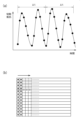
評価部30は、マトリクス作成工程において、図4(a),(b)のような検出結果の時間変化データを、二次元マトリクスであるデータマトリクスに変換する。データマトリクスへの変換方法を、図2(a),(b)の模式図に基づいて説明する。図2(a)は検出結果の時間変化データを示しており、図4(a),(b)のグラフの1方向のデータを模式化したものに相当する。図2(a)の時間変化データにおいては、検出部2によってパラメータ値を検出した検出点を、丸印にて表示している。図2(b)は検出結果に基づいて作成されるデータマトリクスを示している。
In the matrix creation process, the
図2(b)のデータマトリクスにおいて、格子状に表示されている各データ点(ピクセル)には、時間変化データにおける各検出点での検出結果が表示されることになる。つまり、検出部2での検出値が、数値として、データマトリクスの各データ点に格納される。この際、検出値そのものがデータ点に格納されても、検出値に適当な係数を乗じたもの等、検出値の大きさを反映する別の数値に変換されてから、その数値がデータ点に格納されてもよい。
In the data matrix of FIG. 2(b), each data point (pixel) displayed in a grid pattern displays the detection result at each detection point in the time-varying data. In other words, the detection value at the
時間に対して一次元の時間変化データとして与えられた検出結果を、二次元のデータマトリクスに変換するために、時間変化データにおいて、検出結果を一定の時間幅Δtごとに区切る。時間幅Δtは、おおむね、検出結果における波の周期、つまり、回転工具10の回転周期の整数倍の時間となるように設定すればよい。このように、時間幅Δtで区画された検出結果を、1区画ごとに、データマトリクスの縦軸(第一軸)に沿って表示する。図2(b)には、縦軸に沿って区画ごとのデータ点を配置する操作を、細い矢印にて示している。そして、それら区画ごとに縦軸に沿って並べたデータを、時間の順に、横軸(第一軸に交差する第二軸)に沿って並べる。図2(b)には、それら複数の区画のデータを横軸に沿って配置する操作を、太い矢印にて示している。データマトリクスは、画像として表示することもできる。この場合には、各データ点に格納された検出部2での検出結果を示す数値を、明度(輝度)として表示すればよい。つまり、検出結果の数値が大きいほど(例えば切削抵抗が大きいほど)、比例して各データ点の明度が大きくなるように表示すればよい。なお、評価部30においては、上記のように、ディスプレイ画面に、そのようにして得られる画像を表示するように構成してもよいが、データマトリクスを画像情報として扱うことなく、評価部30内で単なる二次元データとして処理するように構成してもよい。
In order to convert the detection results given as one-dimensional time change data to a two-dimensional data matrix, the detection results are divided into certain time intervals Δt in the time change data. The time interval Δt may be set to be roughly the period of the waves in the detection results, that is, an integer multiple of the rotation period of the
図4(a),(b)の切削抵抗の時間変化データのうち、Y方向のデータを、二次元のデータマトリクスに変換したものをそれぞれ、画像表示にて、図5(a),(b)に示している。画像表示としては、切削抵抗の検出値に比例するグレースケールによって、検出結果を表示している(以降の説明においても、データマトリクスを画像表示したものに基づいて、説明を行う)。得られたデータマトリクスの画像表示を見ると、おおむね横方向に沿って、複数の明るい筋が走っている。これらの明るい筋は、時間変化データにおける切削抵抗の波打ち構造の頂部が、時間幅Δtを周期として配列されたものに対応している。 Figures 5(a) and 5(b) show the Y-direction data of the cutting resistance over time change data in Figures 4(a) and 4(b) converted into two-dimensional data matrices as images. The detection results are displayed as grayscales proportional to the detected value of the cutting resistance (the following explanation will also be based on the image display of the data matrix). Looking at the image display of the obtained data matrix, multiple bright streaks can be seen running roughly horizontally. These bright streaks correspond to the peaks of the wavy structure of the cutting resistance in the time change data, arranged in a periodic pattern with a time width of Δt.
次に、切削抵抗の挙動と回転工具10の摩耗の関係について検討する。上にも説明したとおり、回転工具10の摩耗が進行すると、回転工具10とワークWの間に発生する切削抵抗が大きくなる。図3(a),(b)に、実際の回転工具10の切刃を撮影した写真を示している。図3(a)が、回転工具10が摩耗を起こす前(切削加工を開始する前)の状態を示し、図3(b)が、回転工具10が摩耗を起こした後の状態を示している。図3(b)には摩耗幅を符号Lにて表示している。図4(a),(b)は、それぞれ図3(a),(b)の状態の回転工具10に対して実測された切削抵抗の時間変化データである。図4(a)の摩耗前の時間変化データと、図4(b)の摩耗後の時間変化データはいずれも、細かな波打ち構造を示しており、それぞれのデータに特異な特徴を見出すことや、両者の間の系統的な差異を認識することは、目視では容易に行えない。
Next, the relationship between the behavior of the cutting resistance and the wear of the
しかし、一次元の時間変化データを二次元のデータマトリクスに変換すると、摩耗前と摩耗後の差を認識しやすくなる。上に説明したとおり、図5(a),(b)は、図4(a),(b)の切削抵抗の時間変化データにおけるY成分を、それぞれデータマトリクスにしたものである。小さな差ではあるが、図5(a)の摩耗前のデータマトリクスと比較して、図5(b)の摩耗後のデータマトリクスにおいて、画像上で明るく表示された筋の幅が広くなり、また筋の輝度が高くなっているのが分かる。これは、回転工具10の摩耗によって切削抵抗が上昇したことを反映していると解釈される。
However, if the one-dimensional time-varying data is converted into a two-dimensional data matrix, it becomes easier to recognize the difference between before and after wear. As explained above, Figures 5(a) and (b) are data matrices of the Y component of the time-varying cutting resistance data of Figures 4(a) and (b), respectively. Although the difference is small, it can be seen that the width of the brightly displayed streaks on the image is wider and the streaks are brighter in the data matrix of after wear in Figure 5(b) compared to the data matrix of before wear in Figure 5(a). This is interpreted as reflecting an increase in cutting resistance due to wear of the
このように、摩耗前後の切削抵抗の挙動における変化は、時間変化データのままでは、系統的な変化として認識できなかったのに対し、データマトリクスとすることで、明確な傾向として認識可能になる。ただし、図3(b)に示した例では、回転工具10の摩耗が、比較的大きな切刃の欠けに至っており、切削抵抗の変化も大きくなるため、データマトリクスを画像表示したものを視覚的に観察するだけでも、変化を明確に認識することができるが、摩耗が切刃の欠けにまで至っていないなど、摩耗の程度が小さい場合や、摩耗による切削抵抗への影響が小さい場合、また摩耗が生じている領域が小さい場合等には、切削抵抗をデータマトリクスとし、画像表示したとしても、視覚では変化を認識できない可能性がある。また、回転工具10の摩耗以外の現象の寄与や偶発的なノイズの寄与による切削抵抗の変化が、回転工具10の摩耗による切削抵抗の変化に重なった場合に、データマトリクスの画像において、回転工具10の摩耗に起因する切削抵抗の変化を認識するのが難しくなる。さらに、摩耗の種類や進行形態によっては、回転工具10の摩耗によるデータマトリクスの変化が、多様な形態を取り、それら全ての形態の変化を、画像に対する視覚情報で回転工具10の摩耗に対応づけることに、困難を伴う場合も想定される。これらのケースのように、データマトリクスを画像表示したものを視覚認識によって分析する手法では、画像情報から回転工具10の摩耗の進行を明確に認識できない場合もある。また、視覚認識を行う場合には、図5(a),(b)を相互に比較する場合のように、画像に変化が生じていることを認識することで、回転工具10に摩耗が起こっていることは分かっても、摩耗量を定量的に推定することは、実質的に不可能である。そこで、本切削加工装置1の評価部30においては、マトリクス作成工程で作成したデータマトリクスに対して、次の評価工程において、機械学習によって得られた摩耗モデルを適用することで、視覚的には認識しにくい回転工具10の摩耗に対応する特徴も認識し、摩耗幅を定量的に見積もるなど、精度の高い摩耗状態の評価を実行することができる。
In this way, the change in the behavior of the cutting resistance before and after wear cannot be recognized as a systematic change if the data is used as time-varying data, but by using the data matrix, it becomes possible to recognize it as a clear trend. However, in the example shown in FIG. 3(b), the wear of the
評価工程について説明する前に、データマトリクスの作成に関して、別の形態を挙げておく。上で説明した例では、検出部2で検出され、データマトリクスの作成に用いられるパラメータとして、回転工具10とワークWの間の切削抵抗のY成分を用いたが、加速度センサ21によって検出される回転工具10の振動の加速度のY成分を用いて作成したデータマトリクスの例を、画像表示にて、図6(a)に示す。図6(a)の振動の加速度のデータマトリクスにおいても、図5の切削抵抗のデータマトリクスと同様に、回転工具10の回転周期を反映した明瞭な筋状のパターンが生じている。なお、図6(a)の振動の加速度を用いたデータマトリクスの方が、図5の場合よりも筋が密に表示されているのは、データマトリクスに含まれる振動周期の数が多いためである。このように、切削抵抗のみならず、回転工具10の振動の加速度、また回転工具10の摩耗を反映する他のパラメータを用いても、切削抵抗を用いる場合と同様に、二次元のデータマトリクスを作成することができ、さらに、作成したデータマトリクスに対して、後に説明する評価工程を実行することで、回転工具10の摩耗状態を評価することができる。
Before describing the evaluation process, another form of data matrix creation will be mentioned. In the above-described example, the Y component of the cutting resistance between the
以上では、単一のパラメータの検出結果をデータマトリクスの各データ点に格納する形態について説明した。しかし、複数のパラメータのそれぞれの検出値を、同一のデータ点に格納し、複数のパラメータを単一のデータマトリクスに表示することもできる。この場合には、同じ時間に検出された複数のパラメータを、1つのデータ点に格納すればよい。複数のパラメータとしては、種類および検出方向の少なくとも一方が異なる複数のパラメータを任意に選択すればよいが、好ましくは、同じ種類のパラメータを異なる検出方向で検出した結果を、単一のデータマトリクスに表示するようにすればよい。例えば、あるパラメータ(例えば切削抵抗)のX,Y,Zの各方向における検出値が、それぞれa,b,cである場合に、(X,Y,Z)=(a,b,c)とのデータを、各データ点に格納すればよい。このように、異なる複数のパラメータを用いてデータマトリクスを作成することで、1種のみのパラメータを用いる場合よりも情報量が増えるため、次の評価工程において、データマトリクスからの情報抽出による摩耗状態の評価を、高精度で行うことができる。 The above describes a form in which the detection result of a single parameter is stored in each data point of a data matrix. However, it is also possible to store the detection values of multiple parameters in the same data point and display the multiple parameters in a single data matrix. In this case, multiple parameters detected at the same time can be stored in one data point. As the multiple parameters, multiple parameters with at least one different type and detection direction can be arbitrarily selected, but preferably, the results of detecting the same type of parameter in different detection directions can be displayed in a single data matrix. For example, if the detection values of a certain parameter (e.g., cutting resistance) in the X, Y, and Z directions are a, b, and c, respectively, data (X, Y, Z) = (a, b, c) can be stored in each data point. In this way, by creating a data matrix using multiple different parameters, the amount of information increases compared to when only one type of parameter is used, so that in the next evaluation process, the wear state can be evaluated with high accuracy by extracting information from the data matrix.
複数のパラメータの情報を含むデータマトリクスも、画像として表示することができる、この場合には、例えば複数のパラメータを、それぞれ異なる色相に対応づけて、各パラメータの検出値を、それぞれの色相の明度として表現すればよい。そして、データマトリクスの各データ点(ピクセル)において、同じ時間に検出された複数のパラメータに対応する色相および明度を合成し、そのデータ点を、画像の各ピクセルに表示すればよい。例えば、RGB表示のように、3つの原色で色を表現する場合に、3つのパラメータを3つの原色に割り当てて、明度を合成すればよい。上記の例において、(X,Y,Z)=(a,b,c)との数値がデータ点に格納されている場合に、RGB表示を適用するならば、(R,G,B)=(a,b,c)と表現される色が、そのピクセルに表示されることになる。 A data matrix containing information on multiple parameters can also be displayed as an image. In this case, for example, multiple parameters can be associated with different hues, and the detected value of each parameter can be expressed as the brightness of each hue. Then, at each data point (pixel) of the data matrix, the hues and brightness corresponding to the multiple parameters detected at the same time can be synthesized, and the data point can be displayed at each pixel of the image. For example, when expressing a color with three primary colors, as in RGB display, three parameters can be assigned to the three primary colors, and the brightness can be synthesized. In the above example, if the numerical values (X, Y, Z) = (a, b, c) are stored in the data point, if RGB display is applied, the color expressed as (R, G, B) = (a, b, c) will be displayed at that pixel.
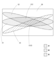
図7に、3方向の切削抵抗を単一のデータ画像に表現したものを、赤、緑、青の3つの原色を含む画像として表示する形態を、模式的に示す。ここでは、X方向の検出値に対応する赤色を縦縞のハッチングで、Y方向の検出値に対応する緑色を横縞のハッチングで、Z方向の検出値に対応する青色を斜めのハッチングで表示している。図7において、画像上の各位置で、赤、緑、青の各色が重なっていない領域C1,C2,C3には、それぞれの色相の色が表示されているが、複数の色が重なっている領域には、2つまたは3つの色相が、それぞれの明度によって重みづけされて合成された色が、表示されている。例えば、3方向のいずれの切削抵抗もゼロである領域C0においては、(R,G,B)=(0,0,0)で黒色に表示される(図ではハッチングのない表示)。一方、3方向の切削抵抗の成分が重畳されている領域C123は、赤、緑、青の3原色が、それぞれの方向の切削抵抗の大きさに比例する明度で合成された色が表示される(図では格子に斜めのハッチングが重なったパターンで表示)。例えば3方向の切削抵抗がいずれも最高水準であるならば、(R,G,B)=(255,255,255)で白色が表示される。また、X方向の成分とY方向の成分の2種が重畳されている領域C12では、赤と緑がそれぞれの明度で合成された色が表示される(図では格子状のパターンで表示)。例えばX方向およびY方向の切削抵抗がともに最高水準であるならば、(R,G,B)=(255,255,0)で黄色が表示される。 Figure 7 shows a schematic diagram of a form in which cutting resistance in three directions is expressed in a single data image and displayed as an image containing the three primary colors of red, green, and blue. Here, red, which corresponds to the detection value in the X direction, is displayed with vertical hatching, green, which corresponds to the detection value in the Y direction, is displayed with horizontal hatching, and blue, which corresponds to the detection value in the Z direction, is displayed with diagonal hatching. In Figure 7, in the areas C1, C2, and C3 where the red, green, and blue colors do not overlap at each position on the image, the colors of each hue are displayed, but in the areas where multiple colors overlap, a color obtained by weighting two or three hues by their respective brightnesses and combining them is displayed. For example, in the area C0 where the cutting resistance in all three directions is zero, (R, G, B) = (0, 0, 0) is displayed in black (no hatching in the figure). On the other hand, in the area C123 where the cutting resistance components in the three directions are superimposed, the three primary colors red, green, and blue are displayed in a color that is a composite of the three primary colors red, green, and blue, with a brightness that is proportional to the magnitude of the cutting resistance in each direction (shown in the figure as a grid pattern with diagonal hatching superimposed). For example, if the cutting resistance in all three directions is at its highest level, (R, G, B) = (255, 255, 255) is displayed as white. In the area C12 where the X-direction component and the Y-direction component are superimposed, a color that is a composite of red and green with their respective brightness is displayed (shown in a grid pattern in the figure). For example, if the cutting resistance in both the X-direction and Y-direction is at its highest level, (R, G, B) = (255, 255, 0) is displayed as yellow.
(2)回転工具の摩耗状態の評価
次に、評価部30において評価工程を実施し、回転工具10の摩耗状態を評価する方法について説明する。評価工程においては、評価部30に記憶されている摩耗モデルを用いて、先のマトリクス作成工程で得られたデータマトリクスから、回転工具10の摩耗状態を評価する。回転工具10の摩耗状態として評価する具体的な事象としては、上記のように、摩耗幅、摩耗の種類、摩耗による回転工具10の交換の要否等、特に限定されるものではないが、以下では摩耗幅を評価する場合を中心に、説明を行う。摩耗幅は、定量的な数値であるため、作業者が明快に認識でき、回転工具10の交換や切削加工条件の見直し等の処置の指標としても利用しやすい。
(2) Evaluation of Wear State of Rotary Tool Next, a method of evaluating the wear state of the
評価工程において利用する摩耗モデルは、過去に取得されたデータマトリクスと回転工具10の摩耗状態との関係を教師データとした機械学習によって得られたモデルである。回転工具10の摩耗状態については、評価対象の回転工具10と同じ種類(型番)の回転工具10を用いて、種々の条件で切削加工試験を行って、摩耗を起こさせたうえで、摩耗幅の実測等によって評価される。そのように評価された摩耗状態が、切削加工試験中に得られたデータマトリクスと対応付けられて、摩耗モデルを作成するための教師データとされる。
The wear model used in the evaluation process is a model obtained by machine learning using the relationship between the previously acquired data matrix and the wear state of the
このようにして、既知のデータマトリクスと回転工具10の摩耗状態との対応関係に基づいて得られた摩耗モデルに、回転工具10の摩耗状態が未知であるデータマトリクス、つまり摩耗状態の評価を実施したい回転工具10に対して実際に得られたデータマトリクスを入力することで、出力として、そのデータマトリクスが取得された際の回転工具10の摩耗状態を評価(推定)することができる。例えば、摩耗モデルが、既知のデータマトリクスと摩耗幅の相関性を示すものである場合に、摩耗幅が未知であるデータマトリクスに対してその摩耗モデルを適用することで、そのデータマトリクスを与える摩耗幅の推定値が、数値として出力される。なお、切削加工装置1で用いられる回転工具10の種類や、切削トルク、回転工具10の回転速度等、切削加工にかかる条件が変更される可能性がある場合には、それらのパラメータに応じた摩耗モデルを評価部30に複数記憶させておき、入力されたパラメータに応じて使用する摩耗モデルを選択できるようにすればよい。あるいはそれらのパラメータまで取り込んで摩耗モデルを構築しておいてもよい。
In this way, by inputting a data matrix in which the wear state of the
機械学習によって摩耗モデルを作成する際に用いる手法としては、教師あり学習が行えるものであれば、特に限定されるものではない。例えば、ニューラルネットワーク、ランダムフォレスト、決定木、バギング、ブースティング、サポートベクターマシン等、公知のモデルを利用することができる。これらの中でも、画像認識に高い能力を示し、二次元情報の解析に好適に利用することができるニューラルネットワーク、中でも畳み込みニューラルネットワーク(CNN)を用いることが好ましい。CNNを用いた摩耗モデルは、データマトリクスを入力層とし、摩耗幅等の摩耗状態を出力層として作成される。入力層に入力されるデータマトリクスは、マトリクス作成工程において作成されたデータマトリクスから、適宜、機械学習に適した所定のサイズの領域を切り出したものとすることが好ましい。公知のCNNと同様に、中間層は、複数の畳み込み層(さらにプーリング層を合わせて含んでもよい)と、全結合層を有し、畳み込み層においては、データマトリクスに対して複数のカーネルが適用される。上記でRGBカラーモデルを用いて説明したように、複数の異なるパラメータの情報が単一のデータマトリクスに含まれる場合には、各パラメータの成分に対して、異なるカーネルを適用してもよい。 The method used to create a wear model by machine learning is not particularly limited as long as it can perform supervised learning. For example, known models such as neural networks, random forests, decision trees, bagging, boosting, and support vector machines can be used. Among these, it is preferable to use a neural network that shows high ability in image recognition and can be suitably used for analyzing two-dimensional information, and in particular a convolutional neural network (CNN). A wear model using a CNN is created by using a data matrix as an input layer and a wear state such as wear width as an output layer. It is preferable that the data matrix input to the input layer is an area of a predetermined size suitable for machine learning that is appropriately cut out from the data matrix created in the matrix creation process. As with a known CNN, the intermediate layer has multiple convolution layers (which may further include a pooling layer) and a fully connected layer, and in the convolution layer, multiple kernels are applied to the data matrix. As explained above using the RGB color model, when information on multiple different parameters is included in a single data matrix, different kernels may be applied to the components of each parameter.
図8に、機械学習によって得られた摩耗モデルを用いて、データマトリクスから回転工具10の摩耗幅を評価した例を示す。図では横軸に摩耗幅の実測値を示し、縦軸に摩耗モデルによって推定された摩耗幅の値を示している。ここで、摩耗モデルは、X,Y,Zの3方向における回転工具10の振動の加速度に基づいて作成されたデータマトリクスと、摩耗幅の関係から、CNNによって構築したものである。図では、丸印(●)にて、機械学習によって摩耗モデルを作成する際に入力層として用いた既知のデータマトリクスそのものを、作成した摩耗モデルに入力して出力された摩耗幅の推定値と、実測された摩耗幅との関係を表示している。一方、四角印(■)にて、機械学習による摩耗モデルの作成には用いなかった未知のデータマトリクスを、摩耗モデルに入力して出力された摩耗幅の推定値と、実測された摩耗幅との関係を表示している。なお、ここで用いている摩耗モデルは、後に説明するノイズの付加をデータマトリクスに対して実施したうえで、作成したものである。
Figure 8 shows an example of evaluating the wear width of the
図8において、丸印(●)にて示される既知のデータマトリクスを対象とした場合については、摩耗幅の推定値と実測値が高い線形性を示しており(近似直線を破線にて表示)、しかも推定値が実測値とほぼ一致している。さらに、四角印(■)にて示される未知のデータマトリクスを対象とした場合にも、データ点が、上記既知のデータマトリクスを対象とした場合の近似直線上によく乗っている。また、推定値が実測値とほぼ一致している。このことは、既知のデータマトリクスを用いた機械学習によって得られた摩耗モデルを、未知のデータマトリクスに適用することで、未知のデータマトリクスに対しても、摩耗幅の推定を高い精度で行えることを意味している。つまり、事前の試験等から既知のデータマトリクスと摩耗幅の対応関係を用いて、摩耗モデルを構築しておけば、以降は、実際の回転工具10に対して摩耗幅を実測しなくても、回転工具10の振動の加速度等、検出部2で検出されたパラメータに基づいて作成されるデータマトリクスから、回転工具10の摩耗幅を評価することができる。
In FIG. 8, when the known data matrix indicated by the circle (●) is used, the estimated wear width and the actual measured wear width show high linearity (the approximate straight line is shown by a dashed line), and the estimated wear width almost coincides with the actual measured wear width. Furthermore, when the unknown data matrix indicated by the square (■) is used, the data points are well on the approximate straight line when the known data matrix is used. The estimated wear width also almost coincides with the actual measured wear width. This means that by applying the wear model obtained by machine learning using the known data matrix to the unknown data matrix, the wear width can be estimated with high accuracy even for the unknown data matrix. In other words, if a wear model is constructed using the correspondence between the known data matrix and the wear width from a prior test, the wear width of the
ここで、機械学習における過学習について検討する。一般に、機械学習においては、過学習が起こる可能性がある。つまり、機械学習によって作成されるモデルが、教師データとして入力された既知のデータに適合しすぎた場合に、未知のデータを入力した際に、正しい出力が得られにくくなる可能性がある。本実施形態にかかる切削加工装置1で用いられる摩耗モデルを機械学習によって作成する場合にも、過学習は起こりうる。過学習が起こると、例えば摩耗モデルの作成に用いた既知のデータマトリクスを摩耗モデルに入力した場合には、摩耗幅の推定を高精度に行えるのに対し、摩耗モデルの作成に用いていない未知のデータマトリクスを摩耗モデルに入力した場合には、摩耗幅を高精度に推定できない事態が生じうる。これは、過学習によって摩耗モデルが既知のデータ群に適合しすぎた結果、未知のデータに対しては、正確に摩耗幅を評価できなくなるために起こる現象である。
Here, overlearning in machine learning will be considered. In general, overlearning may occur in machine learning. In other words, if a model created by machine learning is too compatible with known data input as training data, it may be difficult to obtain a correct output when unknown data is input. Overlearning may also occur when the wear model used in the
過学習は、教師データが少ない場合に起こりやすいため、過学習を抑制する手段の1つとして、摩耗モデルを作成する際に、多様な摩耗状態に対して得られた多数のデータマトリクスを、教師データとして入力すればよい。過学習を解消するための別の手段として、摩耗モデルを作成する際に教師データとして用いるデータマトリクスに、ノイズを付加しておく手法を挙げることができる。ノイズの付加によって、教師データの偏りを解消することで、教師データへの過剰適合が抑制される。例えば、回転工具10の振動の加速度について、検出値から得られたデータマトリクスそのものを、既に説明した図6(a)に示しているが、このデータマトリクスの各ピクセルの値にランダムにノイズを付加したものが、図6(b)となる。図6(a)と図6(b)を比較することで、ノイズ付加によって、筋状のパターンを含む画像全体が、若干不鮮明になっているのが分かる。
Overfitting is likely to occur when there is little training data, so one way to prevent overfitting is to input a large number of data matrices obtained for various wear conditions as training data when creating a wear model. Another way to eliminate overfitting is to add noise to the data matrix used as training data when creating a wear model. By adding noise, the bias of the training data is eliminated, and overfitting to the training data is suppressed. For example, the data matrix itself obtained from the detection value for the acceleration of the vibration of the
図8に示したグラフは、図6(b)のように、データマトリクスを用いて得た摩耗モデルに基づいて推定される摩耗幅と、実測の摩耗幅の関係を示したものである。なお、摩耗モデルの作成に用いたデータマトリクス(学習に使用したデータ)にはノイズを付加したが、摩耗モデルの適用による摩耗幅推定の対象とするデータマトリクス(学習に使用しなかったデータ)には、ノイズは付加していない。このように、ノイズを付加したデータマトリクスを用いて摩耗モデルを作成することで、未知のデータマトリクスに対しても、既知のデータマトリクスの場合と同様に、摩耗幅が正確に推定できている。このことは、摩耗モデルを作成する際のデータマトリクスへのノイズの付加により、過学習を抑制できることを示している。 The graph in Figure 8 shows the relationship between the wear width estimated based on the wear model obtained using a data matrix, as in Figure 6 (b), and the actually measured wear width. Note that noise was added to the data matrix (data used for learning) used to create the wear model, but noise was not added to the data matrix (data not used for learning) that was the target of wear width estimation by applying the wear model. In this way, by creating a wear model using a data matrix with noise added, wear width can be accurately estimated even for unknown data matrices, just as in the case of a known data matrix. This shows that overlearning can be suppressed by adding noise to the data matrix when creating a wear model.
このように、教師データとしてのデータマトリクスへのノイズの付加によって過学習を抑制することで、摩耗モデルを用いた回転工具10の摩耗状態の推定の精度を高めることができる。ただし、検出部2で検出されるパラメータの種類や、回転工具10の摩耗の程度、また回転工具10の摩耗によってパラメータに生じる影響の程度、機械学習に用いる教師データの量や質などによっては、過学習が問題にならない場合もあり、そのような場合には、ノイズの付加を行う必要はない。
In this way, overlearning can be suppressed by adding noise to the data matrix as training data, thereby improving the accuracy of estimating the wear state of the
機械学習にCNNを用いる場合に、過学習が起こるか否か、また過学習の程度は、中間層における層の数や、カーネルのサイズ等、機械学習の諸条件にも依存する。そこで、それら諸条件やノイズ付加の程度を変更しながら、過学習が適切に抑えられた摩耗モデルを構築すればよい。この際、学習曲線を作成し、過学習の抑制の指標として利用すればよい。学習曲線は、エポック(学習パラメータの更新回数)と損失(実測値と推定値のずれ)の関係を示したものであり、既知のデータマトリクス(学習に使用したデータ)に対しても、未知のデータマトリクス(学習に使用しなかったデータ)に対しても、損失がエポックの増加とともに減少する学習曲線が得られれば、過学習が起こっていないと判断することができる。過学習が起こると、未知のデータマトリクスに対する学習曲線において、エポックの増加に対して損失の増大が起こる。 When using CNN for machine learning, whether overfitting occurs and the degree of overfitting also depend on various machine learning conditions, such as the number of layers in the intermediate layer and the kernel size. Therefore, a wear model in which overfitting is appropriately suppressed can be constructed by changing these conditions and the degree of noise addition. In this case, a learning curve can be created and used as an indicator of suppressing overfitting. A learning curve shows the relationship between epochs (the number of times the learning parameters are updated) and loss (the deviation between the actual value and the estimated value). If a learning curve is obtained in which the loss decreases with an increase in epochs for both known data matrices (data used for learning) and unknown data matrices (data not used for learning), it can be determined that overfitting has not occurred. When overfitting occurs, the loss increases with an increase in epochs in the learning curve for an unknown data matrix.
[切削加工装置における回転工具の摩耗状態の評価]
次に、本発明の一実施形態にかかる工具摩耗評価方法について説明する。本実施形態にかかる工具摩耗評価方法は、上記で説明した切削加工装置1を用いて実行することができる。
[Evaluation of wear state of rotary tools in cutting equipment]
Next, a tool wear evaluation method according to an embodiment of the present invention will be described. The tool wear evaluation method according to the present embodiment can be executed by using the
本実施形態にかかる工具摩耗評価方法においては、切削加工装置1を用いて、回転工具10によってワークWの切削加工を行うに際し、検出部2によって、回転工具10の摩耗状態を反映するパラメータを検出する。そして、検出結果の時間変化を用いて、評価部30にてマトリクス作成工程を実施し、二次元のデータマトリクスを作成する。さらに、評価部30において、評価工程を実施し、回転工具10の摩耗状態を評価する。つまり、評価工程において、既知のデータマトリクスと回転工具10の摩耗状態との対応関係を教師データとした機械学習によって作成し、評価部30に記憶させておいた摩耗モデルを、マトリクス作成工程で作成された未知のデータマトリクスに対して適用することで、摩耗幅等、回転工具10の摩耗状態に関する情報を出力する。
In the tool wear evaluation method according to the present embodiment, when cutting the workpiece W with the rotating
本実施形態にかかる工具摩耗評価方法においては、検出部2によるパラメータの検出は、切削加工を行っている間に、リアルタイムで行うが、評価部30によるマトリクス作成工程および評価工程は、切削加工中にリアルタイムで行っても、切削加工がある程度進行してから、あるいは完了してから、まとめて行ってもよい。いずれの場合にも、回転工具10の摩耗状態に関する情報の把握、およびその情報に基づく処置を、早期に行うことが可能となる。特にマトリクス作成工程および評価工程もリアルタイムで実施した場合に、それらの効果が高くなる。評価工程によって、回転工具10の摩耗が進行していることが明らかになった場合に行うべき処置としては、切削加工の停止、回転工具10の点検や交換、切削加工にかかる条件の変更等を挙げることができる。それらの処置は、評価部30から出力される摩耗状態に関する情報を、ディスプレイ画面などを通じて確認した作業者が、行うことができる。あるいは、評価部30から出入力部32を介して情報を入力された制御系31が、それらの処置を自動的に実行するか、またはアラーム等によって処置の実行を作業者に促す形態としてもよい。
In the tool wear evaluation method according to the present embodiment, the
上記で説明した切削加工装置1は、回転工具10による切削中に、検出部2によって、回転工具10の摩耗状態を反映するパラメータを、リアルタイムに検出するものである。そのため、接触式やレーザー式、撮像式等の検査装置を用いて、回転工具10の状態を直接検査する場合とは異なり、回転工具10が回転して切削加工を行っている加工工程の最中に、回転工具10の摩耗状態を評価することができ、回転工具10に摩耗が発生すれば、速やかに、また簡素な工程で、検知することができる。
The
さらに、本切削加工装置1においては、検出部2で検出されたパラメータの挙動に基づく回転工具10の摩耗状態の推定を、機械学習によって得られた摩耗モデルを用いて行っている。この際に用いられる摩耗モデルが、過去に実際に検出部2で検出されたパラメータの挙動に基づくデータマトリクスを、回転工具10の摩耗状態に対応づけたものを教師データとして作成されていることから、検出部2で検出されるパラメータに基づく回転工具10の摩耗状態の評価を、高い精度で行うことができる。
Furthermore, in this
さらに、摩耗モデルの作成、および作成した摩耗モデルを用いた回転工具10の摩耗状態の評価に用いるデータとして、検出部2で検出されたパラメータの時間変化そのものを示す一次元データではなく、パラメータの時間変化を二次元マトリクスであるデータマトリクスとして構成したものを用いることで、回転工具10の摩耗状態に変化が生じた際に、その変化に起因して検出部2に検出されるパラメータに生じる変化を、敏感に検知することができる。また、回転工具10の摩耗状態によって、検出されるパラメータ値に生じる変化のうち、回転工具10の回転の1周期以内など、短い時間スケールで生じる変化も、回転工具10の回転の複数周期にわたるものなど、比較的長い時間スケールで生じる変化も、同一のデータマトリクスに特徴として出現するため、様々な時間スケールで生じる変化を検知し、情報として利用しやすくなる。さらに、画像解析等、二次元情報の解析の分野においては、機械学習の発達が特に著しく、本実施形態にかかる切削加工装置1においても、データを二次元マトリクスの形で扱うことで、特徴の抽出や、抽出した特徴に基づく解析を高精度に行うことができる。それらの結果として、検出部2で検出されるパラメータにおいて、回転工具10の摩耗による変化量が小さい場合や、回転工具10の摩耗以外の要因が寄与している場合、また回転工具10の摩耗を含む諸要因が多様に寄与する場合等、検出されたパラメータと回転工具10の摩耗状態との対応づけが一般的には困難である場合にも、検出部2で検出されたパラメータの時間変化を、データマトリクスとして扱って、機械学習によって得られた摩耗モデルを適用することで、回転工具10の摩耗状態に高精度に対応づけることができる。摩耗モデルを作成する際に教師データとして用いるデータマトリクスにノイズを付与すれば、過学習を抑制して、さらに摩耗状態の評価の精度を高めることができる。
Furthermore, as the data used for creating the wear model and for evaluating the wear state of the
このように、回転工具10による切削を進めながら、回転工具10の摩耗状態に関する情報を取得し、その情報を二次元マトリクス化したうえで、機械学習による摩耗モデルを適用して回転工具10の摩耗状態を評価することで、切削加工を中断しなくても、回転工具10の摩耗状態を、高精度にまた簡便に評価することができる。その評価結果に基づいて、回転工具10の交換や切削加工の停止、加工条件の変更等の処置を、回転工具10の摩耗が深刻になる前に適時に行うことで、摩耗の進んだ回転工具10で切削加工を継続することによる加工品質や加工効率の低下、また切削加工装置1への影響を回避しやすくなる。一方で、回転工具10の個体ごとに、実際の摩耗状態を評価して、交換等の判断を行うことができるので、摩耗がそれほど進行していない回転工具10を予防的に交換する場合と比べて、回転工具10の交換に要するコストや手間を低減し、また切削加工装置1の稼働率を向上させることができる。
In this way, by acquiring information on the wear state of the
以上、本発明の実施形態について詳細に説明したが、本発明は上記実施形態に限定されるものではなく、本発明の要旨を逸脱しない範囲で種々の改変が可能である。 Although the embodiments of the present invention have been described in detail above, the present invention is not limited to the above embodiments, and various modifications are possible without departing from the gist of the present invention.
1 切削加工装置
10 回転工具
11 主軸
12 テーブル
13 固定治具
2 検知部
21 加速度センサ
22 動力計
30 評価部
31 制御系
32 出入力部
W ワーク(被加工材)
1 Cutting
Claims (7)
前記回転工具による切削中に、前記回転工具の摩耗状態を反映する少なくとも1種のパラメータを検出する検出部と、
前記検出部による検出結果を入力され、前記回転工具の摩耗状態を評価する評価部と、を有し、
前記評価部は、
第一軸と、前記第一軸に交差する第二軸を有し、前記検出部による検出結果を示すデータ点を、一定の時間幅ごとに区切って第一軸に沿って配置したものを、第二軸に沿って時間の順に複数並べて表示した二次元マトリクスであるデータマトリクスを作成するマトリクス作成工程と、
前記データマトリクスと前記回転工具の摩耗状態との関係を教師データとした機械学習によって得られた摩耗モデルを用いて、前記マトリクス作成工程において取得されたデータマトリクスから、前記回転工具の摩耗状態を評価する評価工程と、
を実行する切削加工装置。 A rotating tool that cuts a workpiece while rotating;
A detection unit that detects at least one parameter reflecting a wear state of the rotary tool during cutting by the rotary tool;
an evaluation unit that receives a detection result from the detection unit and evaluates a wear state of the rotary tool,
The evaluation unit is
a matrix creation step of creating a data matrix, which is a two-dimensional matrix having a first axis and a second axis intersecting the first axis, in which data points indicating the detection results by the detection unit are arranged along the first axis at intervals of a certain time width, and the data points are arranged in order of time along the second axis;
an evaluation step of evaluating a wear state of the rotating tool from the data matrix acquired in the matrix creation step by using a wear model obtained by machine learning using a relationship between the data matrix and the wear state of the rotating tool as training data;
A cutting processing device that performs the above steps.
前記回転工具の振動の加速度、
前記回転工具または前記被加工材に発生する弾性波、
前記回転工具と前記被加工材との間の切削抵抗、
前記回転工具に供給される主軸電力、
のいずれか少なくとも1つを含む、請求項1に記載の切削加工装置。 The parameter detected by the detection unit is
The acceleration of the vibration of the rotary tool;
Elastic waves generated in the rotary tool or the workpiece;
cutting resistance between the rotary tool and the workpiece;
a spindle power supplied to the rotary tool;
The cutting device according to claim 1 , comprising at least one of the following:
前記データマトリクスにおいては、同一の時間に検出された前記複数のパラメータのそれぞれの検出値が、同一の前記データ点に格納される、請求項1から請求項5のいずれか1項に記載の切削加工装置。 The detection unit detects a plurality of parameters having different types and/or detection directions,
6. The cutting device according to claim 1, wherein in the data matrix, the detected values of the plurality of parameters detected at the same time are stored in the same data point.
前記検出部によって少なくとも1種の前記パラメータを検出したうえで、
前記評価部によって前記マトリクス作成工程および前記評価工程を実施することで、
前記回転工具の摩耗状態を評価する、工具摩耗評価方法。 When the cutting device according to any one of claims 1 to 6 is used to cut the workpiece with the rotary tool,
After detecting at least one of the parameters by the detection unit,
The matrix creation step and the evaluation step are performed by the evaluation unit,
A tool wear evaluation method for evaluating a wear state of the rotary tool.
Priority Applications (1)
| Application Number | Priority Date | Filing Date | Title |
|---|---|---|---|
| JP2021140006A JP7652016B2 (en) | 2021-08-30 | 2021-08-30 | Cutting device and tool wear evaluation method |
Applications Claiming Priority (1)
| Application Number | Priority Date | Filing Date | Title |
|---|---|---|---|
| JP2021140006A JP7652016B2 (en) | 2021-08-30 | 2021-08-30 | Cutting device and tool wear evaluation method |
Publications (2)
| Publication Number | Publication Date |
|---|---|
| JP2023033986A JP2023033986A (en) | 2023-03-13 |
| JP7652016B2 true JP7652016B2 (en) | 2025-03-27 |
Family
ID=85505045
Family Applications (1)
| Application Number | Title | Priority Date | Filing Date |
|---|---|---|---|
| JP2021140006A Active JP7652016B2 (en) | 2021-08-30 | 2021-08-30 | Cutting device and tool wear evaluation method |
Country Status (1)
| Country | Link |
|---|---|
| JP (1) | JP7652016B2 (en) |
Families Citing this family (2)
| Publication number | Priority date | Publication date | Assignee | Title |
|---|---|---|---|---|
| KR20250102940A (en) * | 2023-12-28 | 2025-07-07 | 주식회사 애드아임 | CNC tool life prediction system |
| CN119952536B (en) * | 2025-01-07 | 2025-09-26 | 重庆大学 | PCD cutter-based real-time sensing method for abnormal cutting conditions of ceramic matrix composite |
Citations (5)
| Publication number | Priority date | Publication date | Assignee | Title |
|---|---|---|---|---|
| CN104723171A (en) | 2015-03-17 | 2015-06-24 | 洛阳理工学院 | Cutter wear monitoring method based on current and acoustic emission compound signals |
| JP2018138327A (en) | 2017-02-24 | 2018-09-06 | ファナック株式会社 | Tool state estimation device and machine tool |
| CN110509109A (en) | 2019-07-16 | 2019-11-29 | 西安交通大学 | Tool Wear Monitoring method based on multiple dimensioned depth convolution loop neural network |
| JP2021070114A (en) | 2019-10-31 | 2021-05-06 | 株式会社ジェイテクト | Tool wear prediction system |
| WO2021166790A1 (en) | 2020-02-17 | 2021-08-26 | 京セラ株式会社 | Wear amount estimation model creation method, wear amount estimation method, wear amount estimation model creation device, wear amount estimation model creation program, wear amount estimation device, and wear amount estimation program |
-
2021
- 2021-08-30 JP JP2021140006A patent/JP7652016B2/en active Active
Patent Citations (5)
| Publication number | Priority date | Publication date | Assignee | Title |
|---|---|---|---|---|
| CN104723171A (en) | 2015-03-17 | 2015-06-24 | 洛阳理工学院 | Cutter wear monitoring method based on current and acoustic emission compound signals |
| JP2018138327A (en) | 2017-02-24 | 2018-09-06 | ファナック株式会社 | Tool state estimation device and machine tool |
| CN110509109A (en) | 2019-07-16 | 2019-11-29 | 西安交通大学 | Tool Wear Monitoring method based on multiple dimensioned depth convolution loop neural network |
| JP2021070114A (en) | 2019-10-31 | 2021-05-06 | 株式会社ジェイテクト | Tool wear prediction system |
| WO2021166790A1 (en) | 2020-02-17 | 2021-08-26 | 京セラ株式会社 | Wear amount estimation model creation method, wear amount estimation method, wear amount estimation model creation device, wear amount estimation model creation program, wear amount estimation device, and wear amount estimation program |
Also Published As
| Publication number | Publication date |
|---|---|
| JP2023033986A (en) | 2023-03-13 |
Similar Documents
| Publication | Publication Date | Title |
|---|---|---|
| CN109840900B (en) | A fault online detection system and detection method applied to intelligent manufacturing workshops | |
| US6845340B2 (en) | System and method for machining data management | |
| JP7652016B2 (en) | Cutting device and tool wear evaluation method | |
| JP2021146500A (en) | Method of determining wear state of tool | |
| KR102491716B1 (en) | Machining environment estimation device | |
| TWI649152B (en) | Tool state detection system and method | |
| JP6795562B2 (en) | Inspection equipment and machine learning method | |
| JP2016075663A (en) | System and method for inspecting composite component being manufactured | |
| KR102656853B1 (en) | System for artificial intelligence-based cutting tool wear management and method thereof | |
| CN119855669A (en) | Method for monitoring a machining process in a machine tool, monitoring device and computer program therefor | |
| JP7187397B2 (en) | Re-learning Necessity Determining Method and Re-learning Necessity Determining Device for Diagnosis Model in Machine Tool, Re-learning Necessity Determining Program | |
| CN114034772A (en) | Expert system for detecting potential failure and predicting residual service life of roller | |
| JPH0652181B2 (en) | Abnormality diagnosis device | |
| Ahmad et al. | Milling machine fault detection and identification based on a novel vitality index and temporal-residual network | |
| CN101801603A (en) | Method for the classification of defects and running of lamination cylinder grinding | |
| JP4500876B1 (en) | production management system | |
| JP2021174417A (en) | Industrial inspection system | |
| JP6728089B2 (en) | Position determination device, position determination system including the same, position determination method, and position determination program | |
| JP2000315111A (en) | Diagnosis method and device for equipment and product process abnormal state | |
| TWI399660B (en) | A method of detecting variance by regression model | |
| JP6263519B2 (en) | Inner surface inspection device | |
| KR20240081719A (en) | Real-Time Monitoring Data Clustering Analysis-Based Automatic Tool Replacement Time Detection Method | |
| TW202333890A (en) | Turning tool collapse detection system and method thereof | |
| CN111132819B (en) | Method for the computer-aided processing of quality information of an object and corresponding auxiliary device | |
| KR20230072741A (en) | System and method for diagnosing abnormal operation of machine tool based on deep learning |
Legal Events
| Date | Code | Title | Description |
|---|---|---|---|
| A621 | Written request for application examination |
Free format text: JAPANESE INTERMEDIATE CODE: A621 Effective date: 20240613 |
|
| A131 | Notification of reasons for refusal |
Free format text: JAPANESE INTERMEDIATE CODE: A131 Effective date: 20241112 |
|
| A977 | Report on retrieval |
Free format text: JAPANESE INTERMEDIATE CODE: A971007 Effective date: 20241113 |
|
| A521 | Request for written amendment filed |
Free format text: JAPANESE INTERMEDIATE CODE: A523 Effective date: 20250106 |
|
| TRDD | Decision of grant or rejection written | ||
| A01 | Written decision to grant a patent or to grant a registration (utility model) |
Free format text: JAPANESE INTERMEDIATE CODE: A01 Effective date: 20250212 |
|
| A61 | First payment of annual fees (during grant procedure) |
Free format text: JAPANESE INTERMEDIATE CODE: A61 Effective date: 20250225 |
|
| R150 | Certificate of patent or registration of utility model |
Ref document number: 7652016 Country of ref document: JP Free format text: JAPANESE INTERMEDIATE CODE: R150 |