JP7635404B2 - Carts and transport devices - Google Patents

Carts and transport devices Download PDF

Info

Publication number
JP7635404B2
JP7635404B2 JP2023546671A JP2023546671A JP7635404B2 JP 7635404 B2 JP7635404 B2 JP 7635404B2 JP 2023546671 A JP2023546671 A JP 2023546671A JP 2023546671 A JP2023546671 A JP 2023546671A JP 7635404 B2 JP7635404 B2 JP 7635404B2
Authority
JP
Japan
Prior art keywords
transport vehicle
carriage body
reference surface
trolley
transport
Prior art date
Legal status (The legal status is an assumption and is not a legal conclusion. Google has not performed a legal analysis and makes no representation as to the accuracy of the status listed.)
Active
Application number
JP2023546671A
Other languages
Japanese (ja)
Other versions
JPWO2023037498A1 (en
Inventor
重義 稲垣
英俊 川合
Current Assignee (The listed assignees may be inaccurate. Google has not performed a legal analysis and makes no representation or warranty as to the accuracy of the list.)
Individual
Original Assignee
Individual
Priority date (The priority date is an assumption and is not a legal conclusion. Google has not performed a legal analysis and makes no representation as to the accuracy of the date listed.)
Filing date
Publication date
Application filed by Individual filed Critical Individual
Publication of JPWO2023037498A1 publication Critical patent/JPWO2023037498A1/ja
Application granted granted Critical
Publication of JP7635404B2 publication Critical patent/JP7635404B2/en
Active legal-status Critical Current
Anticipated expiration legal-status Critical

Links

Images

Classifications

    • BPERFORMING OPERATIONS; TRANSPORTING
    • B65CONVEYING; PACKING; STORING; HANDLING THIN OR FILAMENTARY MATERIAL
    • B65GTRANSPORT OR STORAGE DEVICES, e.g. CONVEYORS FOR LOADING OR TIPPING, SHOP CONVEYOR SYSTEMS OR PNEUMATIC TUBE CONVEYORS
    • B65G41/00Supporting frames or bases for conveyors as a whole, e.g. transportable conveyor frames
    • B65G41/02Frames mounted on wheels for movement on rail tracks
    • BPERFORMING OPERATIONS; TRANSPORTING
    • B66HOISTING; LIFTING; HAULING
    • B66FHOISTING, LIFTING, HAULING OR PUSHING, NOT OTHERWISE PROVIDED FOR, e.g. DEVICES WHICH APPLY A LIFTING OR PUSHING FORCE DIRECTLY TO THE SURFACE OF A LOAD
    • B66F9/00Devices for lifting or lowering bulky or heavy goods for loading or unloading purposes
    • B66F9/06Devices for lifting or lowering bulky or heavy goods for loading or unloading purposes movable, with their loads, on wheels or the like, e.g. fork-lift trucks
    • B66F9/063Automatically guided
    • BPERFORMING OPERATIONS; TRANSPORTING
    • B62LAND VEHICLES FOR TRAVELLING OTHERWISE THAN ON RAILS
    • B62BHAND-PROPELLED VEHICLES, e.g. HAND CARTS OR PERAMBULATORS; SLEDGES
    • B62B3/00Hand carts having more than one axis carrying transport wheels; Steering devices therefor; Equipment therefor
    • B62B3/04Hand carts having more than one axis carrying transport wheels; Steering devices therefor; Equipment therefor involving means for grappling or securing in place objects to be carried; Loading or unloading equipment
    • BPERFORMING OPERATIONS; TRANSPORTING
    • B62LAND VEHICLES FOR TRAVELLING OTHERWISE THAN ON RAILS
    • B62BHAND-PROPELLED VEHICLES, e.g. HAND CARTS OR PERAMBULATORS; SLEDGES
    • B62B5/00Accessories or details specially adapted for hand carts
    • B62B5/0006Bumpers; Safety devices
    • BPERFORMING OPERATIONS; TRANSPORTING
    • B65CONVEYING; PACKING; STORING; HANDLING THIN OR FILAMENTARY MATERIAL
    • B65GTRANSPORT OR STORAGE DEVICES, e.g. CONVEYORS FOR LOADING OR TIPPING, SHOP CONVEYOR SYSTEMS OR PNEUMATIC TUBE CONVEYORS
    • B65G2203/00Indexing code relating to control or detection of the articles or the load carriers during conveying
    • B65G2203/02Control or detection
    • B65G2203/0266Control or detection relating to the load carrier(s)
    • B65G2203/0283Position of the load carrier
    • YGENERAL TAGGING OF NEW TECHNOLOGICAL DEVELOPMENTS; GENERAL TAGGING OF CROSS-SECTIONAL TECHNOLOGIES SPANNING OVER SEVERAL SECTIONS OF THE IPC; TECHNICAL SUBJECTS COVERED BY FORMER USPC CROSS-REFERENCE ART COLLECTIONS [XRACs] AND DIGESTS
    • Y02TECHNOLOGIES OR APPLICATIONS FOR MITIGATION OR ADAPTATION AGAINST CLIMATE CHANGE
    • Y02PCLIMATE CHANGE MITIGATION TECHNOLOGIES IN THE PRODUCTION OR PROCESSING OF GOODS
    • Y02P90/00Enabling technologies with a potential contribution to greenhouse gas [GHG] emissions mitigation
    • Y02P90/60Electric or hybrid propulsion means for production processes

Landscapes

  • Engineering & Computer Science (AREA)
  • Transportation (AREA)
  • Mechanical Engineering (AREA)
  • Chemical & Material Sciences (AREA)
  • Combustion & Propulsion (AREA)
  • Structural Engineering (AREA)
  • Civil Engineering (AREA)
  • Life Sciences & Earth Sciences (AREA)
  • Geology (AREA)
  • Handcart (AREA)
  • Control Of Position, Course, Altitude, Or Attitude Of Moving Bodies (AREA)

Description

本明細書は、搬送物を載せて移動可能な台車、およびこの台車を含んで構成される搬送装置に関する。This specification relates to a cart capable of carrying an object to be transported and a transport device including the cart.

近年、物流や生産の省力化を推進するために、物流倉庫内や生産工場内で搬送物を搬送する無人搬送車の適用が進められている。また、最大積載重量を超過した搬送物や大型で不安定な搬送物などに対応するために、搬送物を載せた台車を牽引しながら走行する無人搬送車が用いられる。この種の牽引タイプの台車および搬送車の一技術例が、特許文献1に開示されている。In recent years, automated guided vehicles have been increasingly used to transport goods within logistics warehouses and production plants in order to promote labor-saving in logistics and production. In addition, to handle goods that exceed the maximum load weight or are large and unstable, automated guided vehicles that travel while towing a cart carrying the goods are used. One technical example of this type of towing type cart and transport vehicle is disclosed in Patent Document 1.

特許文献1に開示された部品搬送装置は、トレイが搭載される搭載部および車輪を有するカート(台車)と、連結機構を介してカートと相対移動可能に連結される無人搬送車と、を備える。さらに、相対移動可能な連結機構の一実施形態として、カートに設けられた円形の開口と、無人搬送車に弾性部材を介して設けられたシャフトとを二組備え、開口の内部でシャフトが移動する構成が開示されている。これによれば、多数の部品を保持するトレイを搬送して、部品を適切に管理できる、とされている。The part transport device disclosed in Patent Document 1 includes a cart (trolley) having wheels and a mounting section on which a tray is mounted, and an automated guided vehicle that is connected to the cart via a connecting mechanism so that the cart can move relatively. Furthermore, as one embodiment of the relatively movable connecting mechanism, a configuration is disclosed that includes two sets of circular openings in the cart and shafts connected to the automated guided vehicle via elastic members, with the shafts moving inside the openings. This is said to enable the parts to be managed appropriately by transporting trays that hold a large number of parts.

特開2019-91770号公報JP 2019-91770 A

ところで、特許文献1に開示された部品搬送装置では、無人搬送車の方向転換走行や弾性部材の伸縮などに起因して開口とシャフトの相対位置関係が変化し、カートと無人搬送車の位置関係や姿勢(向き)が一致しない状態で走行することが生じ得る。これによると、無人搬送車が正規の停止位置に正規の姿勢で停止しても、カートの位置や姿勢がずれる場合が発生する。この場合、カート上のトレイは、位置や姿勢のずれにより積み降ろしに支障が生じるおそれがある。However, in the part conveying device disclosed in Patent Document 1, the relative positional relationship between the opening and the shaft can change due to the directional changes of the automated guided vehicle or the expansion and contraction of the elastic member, causing the cart and the automated guided vehicle to travel in a state where their positions and postures (orientations) do not match. As a result, even if the automated guided vehicle stops in the correct posture at the correct stopping position, the position and posture of the cart may shift. In this case, the tray on the cart may be unable to be loaded or unloaded due to the shift in position or posture.

それゆえ、本明細書では、停止するときの位置および姿勢を高い精度で管理することができる台車、および、この台車を含んで構成される搬送装置を提供することを解決すべき課題とする。Therefore, the problem to be solved in this specification is to provide a cart whose position and posture when stopped can be managed with high precision, and a conveying device including this cart.

本明細書は、搬送物を載せる荷台および走行用の車輪を有する台車本体と、前記台車本体の下側に進入した状態の搬送車に対して前記台車本体の左右方向の位置を位置決めするとともに、前記搬送車に対する前記台車本体の姿勢変化を許容しつつ、前記搬送車に対して前記台車本体を牽引可能に連結する連結部と、前記台車本体の前後方向の正面に設けられ、前記台車本体が前記搬送車に牽引されて搬送目標まで移動するときに、前記搬送目標に設けられた基準面に対して左右方向に離隔した少なくとも二点で当接することにより、前後方向の所定位置に前記台車本体を位置決めするとともに、前記基準面に対して前記台車本体を正対させるバンパー部と、を備える台車を開示する。This specification discloses a trolley that includes a trolley body having a platform for placing an article to be transported and wheels for traveling; a coupling section that positions the trolley body in the left-right direction relative to a transport vehicle that has entered underneath the trolley body and connects the trolley body to the transport vehicle so that it can be towed while allowing the attitude of the trolley body to change relative to the transport vehicle; and a bumper section that is provided on the front side of the trolley body in the front-to-rear direction and that, when the trolley body is towed by the transport vehicle and moves to the transport target, abuts against a reference surface provided on the transport target at at least two points spaced apart in the left-right direction, thereby positioning the trolley body at a predetermined position in the front-to-rear direction and facing the trolley body directly relative to the reference surface.

また、本明細書は、上記した台車と、前記台車本体の下側に進入可能な前記搬送車と、を備える搬送装置を開示する。This specification also discloses a conveying device comprising the above-mentioned trolley and a conveying vehicle capable of entering the underside of the trolley body.

開示した台車や搬送装置において、台車本体は、連結された搬送車に対して左右方向の位置が位置決めされるが、搬送車に対する姿勢(向き)が変化し得る。それでも、台車が搬送車に牽引されて搬送目標まで移動するときに、バンパー部の左右方向に離隔した少なくとも二点が基準面に対して当接することにより、台車本体は、前後方向の所定位置に位置決めされ、かつ基準面に対して正対する姿勢となる。したがって、台車が停止するときの位置および姿勢を高い精度で管理することができる。 In the disclosed trolley and transport device, the trolley body is positioned in the left-right direction relative to the connected transport vehicle, but its attitude (orientation) relative to the transport vehicle can change. Even so, when the trolley is towed by the transport vehicle and moves to the transport target, at least two points spaced apart in the left-right direction of the bumper section abut against a reference surface, so that the trolley body is positioned at a predetermined position in the front-rear direction and is oriented directly facing the reference surface. Therefore, the position and attitude of the trolley when it stops can be managed with high precision.

実施形態の台車を含んで構成される搬送装置の斜視図であり、搬送物を載せた状態が示されている。1 is a perspective view of a conveying device including a dolly according to an embodiment, showing a state in which an object to be conveyed is placed on the conveying device. 実施形態の台車の単体斜視図である。FIG. 2 is a perspective view of the bogie according to the embodiment. 搬送装置を構成する搬送車の単体斜視図である。FIG. 2 is a perspective view of a single transport vehicle constituting the transport device. 連結部の構成を示す部分透視斜視図である。FIG. 4 is a partial perspective view showing the configuration of a connecting portion. 台車側の受電コネクタおよび搬送車側の給電コネクタを示す部分斜視図である。FIG. 4 is a partial perspective view showing a power receiving connector on the dolly side and a power supply connector on the transport vehicle side. 搬送装置の正面図である。FIG. 搬送装置の右側面図である。FIG. 位置決め部を構成するバンパー部、支持部、弾性部材、および検出部を説明する部分斜視図である。4 is a partial perspective view illustrating a bumper portion, a support portion, an elastic member, and a detection portion that configure the positioning portion. FIG. バンパー部が基準面に当接したことを検出部が検出している状態を示す部分斜視図である。11 is a partial perspective view showing a state in which a detection unit detects that a bumper portion has come into contact with a reference surface; FIG. 搬送装置が搬送目標まで走行した状況を示す斜視図である。FIG. 13 is a perspective view showing a state in which the transport device has traveled to the transport target. 固定側通信部および可動側通信部の構成および機能を模式的に説明する平面図である。3 is a plan view for illustrating the configurations and functions of a fixed-side communication unit and a movable-side communication unit. FIG. 台車と搬送車の姿勢が相違して、バンパー部の左前端が基準面に当接したときの作用を模式的に説明する平面図である。13 is a plan view for explaining a schematic operation when the carriage and the transport vehicle are in different postures and the left front end of the bumper portion abuts against a reference surface. FIG. コロ部材をもつバンパー部の平面図である。FIG. 4 is a plan view of a bumper portion having roller members.

1.搬送装置1の概要
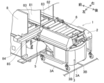
まず、実施形態の台車2を含んで構成される搬送装置1の概要について、図1を参考にして説明する。搬送装置1は、台車2および搬送車3を含んで構成される。図1の右上の矢印に示されるように、搬送装置1、台車2、および搬送車3の前後左右を便宜的に定める。台車2および搬送車3は、前後方向に延びる中心線に対して概ね左右対称に構成される。台車2は、連結部4(詳細後述)によって搬送車3に連結される。搬送車3は、台車2の下側に後方から進入し、連結された台車2を牽引して移動させ、台車2の後方に退出する。
1. Overview of the conveying device 1 First, an overview of the conveying device 1 including the dolly 2 of the embodiment will be described with reference to FIG. 1. The conveying device 1 includes the dolly 2 and the conveying vehicle 3. As shown by the arrows in the upper right of FIG. 1, the front, rear, left and right of the conveying device 1, the dolly 2 and the conveying vehicle 3 are conveniently defined. The dolly 2 and the conveying vehicle 3 are configured approximately symmetrically with respect to a center line extending in the front-rear direction. The dolly 2 is connected to the conveying vehicle 3 by a connecting portion 4 (described in detail later). The conveying vehicle 3 enters the underside of the dolly 2 from the rear, pulls and moves the connected dolly 2, and exits behind the dolly 2.

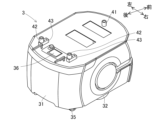
搬送装置1は、複数の搬送目標の間で搬送物Cを搬送する。搬送物Cとして、後側に開口部をもつ収納ケースを例示することができる。この搬送物C(収納ケース)は、開口部から内部に収納する部材の点数が多い場合に重量物となり、搬送車3の最大積載荷重を超過する場合がある。したがって、搬送装置1は、搬送物Cを載せた台車2を搬送車3が牽引する方法により、搬送物Cを搬送する。また、搬送目標として、搬送物Cを収容する収容装置8(詳細後述)を例示することができる。The conveying device 1 conveys the transported item C between multiple transport targets. An example of the transported item C is a storage case with an opening on the rear side. This transported item C (storage case) becomes heavy when a large number of items are to be stored inside through the opening, and may exceed the maximum load capacity of the transport vehicle 3. Therefore, the conveying device 1 conveys the transported item C by having the transport vehicle 3 pull a cart 2 carrying the transported item C. Another example of the transport target is a storage device 8 (described in detail below) that stores the transported item C.

2.台車本体20
実施形態の台車2は、台車本体20、連結部4、および位置決め部5などで構成される。図2等に示されるように、台車本体20は、荷台21、左右の側面部22、左右の脚部23、2個の前車輪24、および2個の後車輪25などで構成される。また、荷台21には、連結部4の一部、位置決め部5、および可動側通信部(71、72)が配置される(これらについては後で別途説明する)。荷台21は、搬送物Cを載せる部位である。荷台21は、平面視で概ね長方形に形成され、床面から離隔して水平に配置される。荷台21は、その上面に積み降ろし部6を有する。
2. Cart body 20
The dolly 2 of the embodiment is composed of a dolly body 20, a coupling section 4, a positioning section 5, and the like. As shown in FIG. 2 and other figures, the dolly body 20 is composed of a loading platform 21, left and right side sections 22, left and right legs 23, two front wheels 24, and two rear wheels 25. In addition, a part of the coupling section 4, the positioning section 5, and a movable side communication section (71, 72) are arranged on the loading platform 21 (these will be described separately later). The loading platform 21 is a portion on which the transported object C is placed. The loading platform 21 is formed in a roughly rectangular shape in a plan view, and is arranged horizontally away from the floor surface. The loading platform 21 has a loading and unloading section 6 on its upper surface.

積み降ろし部6は、搬送物Cを荷台21の正面から前後方向に積み降ろしする。積み降ろし部6は、主ローラ61、6個の駆動ローラ62、ガイドローラ63、係止機構64、操作パネル66、および図略の駆動モータなどで構成される。3種類のローラは、左右方向に延在する円柱状または円筒状の部材であり、中心軸の回りに自転可能に支持されている。荷台21の前側から後側に向かって、ガイドローラ63、3個の駆動ローラ62、主ローラ61、および3個の駆動ローラ62が記載順に配置される。The loading/unloading section 6 loads and unloads the transported goods C from the front of the loading platform 21 in the front-rear direction. The loading/unloading section 6 is composed of a main roller 61, six drive rollers 62, a guide roller 63, a locking mechanism 64, an operation panel 66, and a drive motor (not shown). The three types of rollers are cylindrical or cylindrical members extending in the left-right direction and supported so as to be rotatable around a central axis. From the front to the rear of the loading platform 21, the guide roller 63, the three drive rollers 62, the main roller 61, and the three drive rollers 62 are arranged in the order shown.

主ローラ61は、駆動モータの正回転および逆回転によって駆動され、正方向および逆方向に自転する。6個の駆動ローラ62は、図略の伝達ベルトによって主ローラ61に連結され、主ローラ61と同じ回転方向に同じ回転速度で同期して自転する。ガイドローラ63は、駆動力が付与されず、フリーで自転することができる。主ローラ61および駆動ローラ62の正方向の自転により搬送物Cが積まれ、逆方向の自転により搬送物Cが降ろされる。駆動モータの始動および停止の制御、ならびに回転方向の制御は、図略の台車制御部から行われる。 The main roller 61 is driven by the forward and reverse rotation of the drive motor, and rotates in the forward and reverse directions. The six drive rollers 62 are connected to the main roller 61 by a transmission belt (not shown), and rotate synchronously at the same rotational direction and speed as the main roller 61. No driving force is applied to the guide roller 63, which can rotate freely. The transported item C is loaded by the forward rotation of the main roller 61 and drive roller 62, and is unloaded by their reverse rotation. The start and stop of the drive motor, as well as the rotation direction, are controlled by a trolley control unit (not shown).

係止機構64は、最後部の駆動ローラ62の後方に配置される。係止機構64は、係止フック65を用いて積まれた搬送物Cを係止する。係止フック65は、その前側が上方に屈曲するとともに、弾性部材を用いて上下方向に揺動可能に支持される。搬送物Cが積まれるとき、係止フック65は、一旦下降してから上昇することにより、搬送物Cの後端に設けられた被係止部を自動的に係止する。または、係止フック65は、搬送物Cの底部に設けられた被係止孔に自動的に嵌入する。一方、搬送物Cが降ろされる直前に、係止フック65は、図略の電磁ソレノイドによって下降駆動され、搬送物Cの係止を解除する。電磁ソレノイドは、台車制御部から制御される。The locking mechanism 64 is disposed behind the rearmost drive roller 62. The locking mechanism 64 locks the stacked transported goods C using a locking hook 65. The front side of the locking hook 65 is bent upward and is supported by an elastic member so that it can swing up and down. When the transported goods C are stacked, the locking hook 65 descends once and then ascends, automatically locking the locking part provided at the rear end of the transported goods C. Alternatively, the locking hook 65 automatically fits into the locking hole provided at the bottom of the transported goods C. Meanwhile, just before the transported goods C are lowered, the locking hook 65 is driven downward by an electromagnetic solenoid (not shown) to release the lock on the transported goods C. The electromagnetic solenoid is controlled by the trolley control unit.

上記したように、積み降ろし部6の積み降ろし動作は、主に台車制御部からの制御によって自動で行われる。一方、荷台21の後部に配置された操作パネル66は、積み降ろし部6に係る一部の手動操作に用いられる。例えば、操作パネル66は、積み降ろし部6がエラー停止した場合のエラー解除操作や、積み降ろし部6の非常停止操作に用いられる。積み降ろし部6が安定した積み降ろし動作を行うために、台車2は、搬送目標ごとに設定された停止位置に正確に停止し、かつ搬送目標に正対することが重要となる。As described above, the loading and unloading operations of the loading and unloading unit 6 are mainly performed automatically under control of the trolley control unit. Meanwhile, the operation panel 66 located at the rear of the platform 21 is used for some of the manual operations related to the loading and unloading unit 6. For example, the operation panel 66 is used for an error release operation when the loading and unloading unit 6 stops due to an error, and for an emergency stop operation of the loading and unloading unit 6. In order for the loading and unloading unit 6 to perform stable loading and unloading operations, it is important that the trolley 2 stops accurately at the stop position set for each transport target and faces the transport target directly.

左右の側面部22は、荷台21の左縁および右縁から下方に延びるように設けられる。荷台21の下側の左右の側面部22の間に、搬送車3が進入する空間が区画される。側面部22の各々の下側に、前後方向に延在する左右の脚部23が設けられる。脚部23の前側下部に走行用の前車輪24が設けられ、脚部23の後側下部に走行用の後車輪25が設けられる。合計で4個の前車輪24および後車輪25は、走行方向が可変の自在車輪である。また、2個の後車輪25には、ストッパ26が付加されている。The left and right side sections 22 are provided so as to extend downward from the left and right edges of the loading platform 21. A space for the transport vehicle 3 to enter is defined between the left and right side sections 22 on the underside of the loading platform 21. Left and right legs 23 extending in the front-to-rear direction are provided on the underside of each of the side sections 22. Front wheels 24 for running are provided on the front lower part of the legs 23, and rear wheels 25 for running are provided on the rear lower part of the legs 23. A total of four front wheels 24 and rear wheels 25 are swivel wheels whose running direction can be changed. In addition, stoppers 26 are attached to the two rear wheels 25.

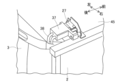
荷台21は、さらに受電コネクタ27を有する。受電コネクタ27は、図5に示されるように、荷台21の底板45の上面の後右側に設けられる。受電コネクタ27は、搬送車3側の給電コネクタ37に嵌合される。給電コネクタ37は、電源ケーブル38を用いて搬送車3が内蔵する図略のバッテリに接続されている。したがって、受電コネクタ27は、給電コネクタ37に嵌合して、積み降ろし部6、台車制御部、および電磁ソレノイドを駆動する電力を搬送車3側のバッテリから受け取ることができる。これによれば、台車2は、バッテリが不要となり、軽量化が実現される。 The loading platform 21 further has a power receiving connector 27. As shown in FIG. 5, the power receiving connector 27 is provided on the rear right side of the upper surface of the bottom plate 45 of the loading platform 21. The power receiving connector 27 is fitted into a power supply connector 37 on the transport vehicle 3 side. The power supply connector 37 is connected to a battery (not shown) built into the transport vehicle 3 using a power cable 38. Therefore, the power receiving connector 27 can be fitted into the power supply connector 37 to receive power to drive the loading/unloading unit 6, the cart control unit, and the electromagnetic solenoid from the battery on the transport vehicle 3 side. This eliminates the need for a battery in the cart 2, making it lighter.

3.搬送車3
搬送車3は、図3等に示されるように、車両本体31、2個の駆動車輪32、2個の前車輪34、2個の後車輪35、操作パネル36、前述した給電コネクタ37、テープ検出部39、および図略の走行モータなどで構成される。また、搬送車3は、連結部4の残部が配置される(これについては後で別途説明する)。車両本体31は、概ね前後方向に長い直方体形状で、平面視で四隅に丸みをもつ形状に形成されている。車両本体31は、床面からわずかに離隔して水平に配置される。
3. Transport vehicle 3
As shown in Fig. 3 and other figures, the transport vehicle 3 is composed of a vehicle body 31, two drive wheels 32, two front wheels 34, two rear wheels 35, an operation panel 36, the power supply connector 37 described above, a tape detection unit 39, and a running motor (not shown). The remaining part of the coupling unit 4 is also arranged on the transport vehicle 3 (this will be described separately later). The vehicle body 31 is formed in a shape of a rectangular parallelepiped that is generally long in the front-rear direction and has rounded corners in a plan view. The vehicle body 31 is arranged horizontally and slightly spaced from the floor surface.

2個の駆動車輪32は、車両本体31の下側の前後方向の中間位置に、左右方向に並んで配置される(図6、図7参照)。駆動車輪32の各々は、走行モータの正回転および逆回転によって駆動される。2個の駆動車輪32は、互いに異なる回転速度や、互いに異なる回転方向での回転が可能となっている。これにより、搬送車3の前進、後退、および方向転換が自在とされる。走行モータの始動、停止および回転方向の制御、ならびに走行モータが出力する走行駆動力の調整は、図略の搬送車制御部から行われる。当然ながら、走行駆動力の増減にしたがい、駆動車輪32の回転速度および搬送車3の走行速度は変化する。The two drive wheels 32 are arranged side by side in the left-right direction at a central position in the front-rear direction on the underside of the vehicle body 31 (see Figures 6 and 7). Each of the drive wheels 32 is driven by forward and reverse rotation of the travel motor. The two drive wheels 32 are capable of rotating at different rotation speeds and in different rotation directions. This allows the transport vehicle 3 to move forward, backward, and change direction freely. The start, stop, and rotation direction of the travel motor are controlled, and the travel driving force output by the travel motor is adjusted by a transport vehicle control unit (not shown). Naturally, the rotation speed of the drive wheels 32 and the travel speed of the transport vehicle 3 change as the travel driving force increases or decreases.

2個の前車輪34は、車両本体31の下側の前寄り位置に、左右に離隔して配置される。2個の後車輪35は、車両本体31の下側の後寄り位置に、左右に離隔して配置される。合計で4個の前車輪34および後車輪35は、走行方向を変更することができる自在車輪である。前車輪34および後車輪35は、2個の駆動車輪32の回転状況に追従して従動回転する。図6に示されるように、左右の車輪間の距離すなわちトレッド幅は、駆動車輪32で最大とされ、前車輪34で最小とされ、後車輪35で中間値とされている。駆動車輪32のトレッド幅が最大であることにより、搬送車3の良好な操舵性能が確保される。The two front wheels 34 are arranged at a distance from each other on the left and right sides of the lower front side of the vehicle body 31. The two rear wheels 35 are arranged at a distance from each other on the lower rear side of the vehicle body 31. A total of four front wheels 34 and rear wheels 35 are free-wheeling wheels that can change the direction of travel. The front wheels 34 and rear wheels 35 rotate in response to the rotation of the two drive wheels 32. As shown in FIG. 6, the distance between the left and right wheels, i.e., the tread width, is maximum for the drive wheels 32, minimum for the front wheels 34, and intermediate for the rear wheels 35. The maximum tread width of the drive wheels 32 ensures good steering performance of the transport vehicle 3.

テープ検出部39は、車両本体31の下側の中心線上の前寄り位置および後寄り位置に、前後一対の形態で設けられる(図6参照)。テープ検出部39は、床面に設けられた経路表示テープ3A(図10参照)を検出して、検出結果を搬送車制御部に出力する。経路表示テープ3Aは、搬送車3の走行経路を表示するものである。搬送車制御部は、搬送車3が経路表示テープ3Aに沿って走行するように制御する。経路表示テープ3Aとして、磁気表示方式や光学表示方式のテープを用いることができる。テープ検出部39は、経路表示テープ3Aの表示方式に対応する検出方式とされる。The tape detection units 39 are provided in a pair, front and rear, at positions toward the front and rear on the center line of the underside of the vehicle body 31 (see FIG. 6). The tape detection units 39 detect the route display tape 3A (see FIG. 10) provided on the floor surface and output the detection results to the transport vehicle control unit. The route display tape 3A displays the travel route of the transport vehicle 3. The transport vehicle control unit controls the transport vehicle 3 so that it travels along the route display tape 3A. Tapes using a magnetic display method or an optical display method can be used as the route display tape 3A. The tape detection units 39 use a detection method that corresponds to the display method of the route display tape 3A.

また、テープ検出部39は、経路表示テープ3Aによって示される走行経路の分岐点3Bを検出することができる。搬送車3が分岐点3Bを通過した後の走行経路は、搬送車制御部によって選択される。搬送車制御部は、テープ検出部39による経路表示テープ3Aの検出結果と、駆動車輪32の制御量とを用いて、搬送車3の現在位置、姿勢(向き)、および走行速度を演算推定し、これらに基づいて以降の搬送車3の走行を制御する。 The tape detection unit 39 can also detect a branch point 3B of the travel route indicated by the route display tape 3A. The travel route after the transport vehicle 3 passes the branch point 3B is selected by the transport vehicle control unit. The transport vehicle control unit calculates and estimates the current position, attitude (direction), and travel speed of the transport vehicle 3 using the detection result of the route display tape 3A by the tape detection unit 39 and the control amount of the drive wheels 32, and controls the subsequent travel of the transport vehicle 3 based on these.

上記したように、搬送車3の走行は、主に搬送車制御部からの制御によって自動で行われる。一方、車両本体31の上面の後部に配置された操作パネル36は、搬送車3に係る一部の手動操作に用いられる。例えば、操作パネル36は、搬送車3がエラー停止した場合のエラー解除操作や、搬送車3の非常停止操作に用いられる。As described above, the transport vehicle 3 travels automatically, mainly under control of the transport vehicle control unit. Meanwhile, the operation panel 36 located at the rear of the top surface of the vehicle body 31 is used for some manual operations related to the transport vehicle 3. For example, the operation panel 36 is used to clear errors when the transport vehicle 3 stops due to an error, and to perform an emergency stop operation for the transport vehicle 3.

4.連結部4
連結部4は、図4に示されるように、荷台21の下部の底板45と搬送車3の上面の間に配置される。連結部4は、台車本体20の下側に進入した状態の搬送車3に対して、台車本体20を牽引可能に連結する。連結部4は、搬送車3の上面に設けられた3個の連結ピン、荷台21の底板45に設けられた前側係止部材46および左右一対の切換機構4Aなどで構成される。なお、図4において、底板45が透視されている。
4. Connection part 4
As shown in Fig. 4, the connecting part 4 is disposed between a bottom plate 45 at the bottom of the platform 21 and the upper surface of the transport vehicle 3. The connecting part 4 connects the cart body 20 to the transport vehicle 3 that has entered under the cart body 20 so that the cart body 20 can be towed. The connecting part 4 is composed of three connecting pins provided on the upper surface of the transport vehicle 3, a front locking member 46 provided on the bottom plate 45 of the platform 21, and a pair of left and right switching mechanisms 4A. Note that the bottom plate 45 is seen through in Fig. 4.

図3および図4に示されるように、搬送車3の上面の左右方向の中央の前寄り位置に、前側連結ピン41が立てて設けられる。前側連結ピン41は、金属性の丸棒の外周側に円筒形のウレタンゴムが嵌められて形成される。また、搬送車3の上面の右後部の位置および左後部の位置に、左右一対の後側連結ピン42が立てて設けられる。後側連結ピン42は、前側連結ピン41と同一材質で同一形状に形成される。後側連結ピン42は、搬送車3の上面にスペーサ43を介して取り付けられ、前側連結ピン41よりも高く配置される。 As shown in Figures 3 and 4, a front connecting pin 41 is provided upright at a front position in the center of the left-right direction on the top surface of the transport vehicle 3. The front connecting pin 41 is formed by fitting cylindrical urethane rubber onto the outer periphery of a metallic round bar. In addition, a pair of left and right rear connecting pins 42 are provided upright at the right rear position and the left rear position on the top surface of the transport vehicle 3. The rear connecting pins 42 are formed of the same material and have the same shape as the front connecting pin 41. The rear connecting pin 42 is attached to the top surface of the transport vehicle 3 via a spacer 43, and is positioned higher than the front connecting pin 41.

一方、荷台21の底板45は、前縁および後縁が下方に折り曲げられている。底板45の下面の左右方向の中央の前寄り位置に、前側係止部材46が設けられる。前側係止部材46は、平面視でクランク形状に形成されており、後方に開口する収容部をもつ。前側係止部材46の収容部は、概ね中間高さに最狭部をもちつつ上下では拡がったテーパ形状の内壁面をもつ。前側係止部材46の最狭部における開口幅寸法は、前側連結ピン41の直径に概ね等しいか、または負の公差を許容して等しく設定される。 Meanwhile, the front and rear edges of the bottom plate 45 of the loading platform 21 are bent downwards. A front locking member 46 is provided on the underside of the bottom plate 45 at a position toward the front of the left-right center. The front locking member 46 is formed in a crank shape in a plan view, and has a storage section that opens to the rear. The storage section of the front locking member 46 has a tapered inner wall surface that has its narrowest part roughly at the mid-height and widens at the top and bottom. The opening width dimension at the narrowest part of the front locking member 46 is roughly equal to the diameter of the front connecting pin 41, or is set to be equal while allowing a negative tolerance.

搬送車3が台車本体20の下側に進入するとき、前側係止部材46の収容部内に向かって前側連結ピン41が後方から進入する。前側連結ピン41は、前側係止部材46の最狭部に内接し、最狭部以外の内壁面には殆ど接しない。また、前側連結ピン41が最狭部に内接するとき、外周側のウレタンゴムの微小な変形が許容される。これにより、前側係止部材46の収容部は、前側連結ピン41を係止して左右方向の移動を許容しない。したがって、搬送車3に対する台車本体20の左右方向の位置が位置決めされる。一方、前側係止部材46の収容部は、前側連結ピン41の左右方向および前後方向の倒れを許容する。したがって、搬送車3に対する台車本体20の左右方向および前後方向の相対的な傾きが許容されるので、床面にうねりが生じていたとしても、搬送車3および台車2はスムーズに走行することができる。また、前側連結ピン41は、前側係止部材46の収容部内を前後方向に相対移動可能となっている。When the transport vehicle 3 enters the underside of the dolly body 20, the front connecting pin 41 enters from the rear toward the inside of the storage section of the front locking member 46. The front connecting pin 41 is inscribed in the narrowest part of the front locking member 46 and hardly comes into contact with the inner wall surface other than the narrowest part. In addition, when the front connecting pin 41 is inscribed in the narrowest part, slight deformation of the urethane rubber on the outer periphery is allowed. As a result, the storage section of the front locking member 46 locks the front connecting pin 41 and does not allow movement in the left-right direction. Therefore, the left-right position of the dolly body 20 relative to the transport vehicle 3 is determined. On the other hand, the storage section of the front locking member 46 allows the front connecting pin 41 to fall in the left-right and front-back directions. Therefore, since the relative inclination of the dolly body 20 relative to the transport vehicle 3 in the left-right and front-back directions is allowed, the transport vehicle 3 and the dolly 2 can run smoothly even if the floor surface is undulated. Further, the front connecting pin 41 is capable of moving relatively in the front-rear direction within the housing portion of the front locking member 46 .

さらに、底板45の下側に、左右一対の棒形状または板形状のガイド部材47が設けられる。左右一対のガイド部材47は、荷台21の後側から前側に進むにつれて前側係止部材46の収容部に徐々に接近するように斜めに配置される。ガイド部材47は、搬送車3が台車本体20の下側に進入する際に両者の中心線がずれていた場合に、前側連結ピン41を前側係止部材46の収容部に向かって案内する。 Furthermore, a pair of left and right rod- or plate-shaped guide members 47 are provided below the bottom plate 45. The pair of left and right guide members 47 are arranged at an angle so as to gradually approach the storage portion of the front locking member 46 as they proceed from the rear to the front of the loading platform 21. The guide members 47 guide the front connecting pin 41 toward the storage portion of the front locking member 46 if the center lines of the two are misaligned when the transport vehicle 3 enters the underside of the trolley body 20.

また、底板45の後縁は、その中央部分がクランク形状に切り欠かれたクランク縁部48、および切り欠かれていない左右の後縁部49からなる。左右の後縁部49の各々に、切換機構4Aが設けられる。左右一対の切換機構4Aの各々は、機構本体4B、後側係止部材4C、および操作ノブ4Dなどで構成される。The rear edge of the bottom plate 45 is made up of a crank edge portion 48, the center of which is cut into a crank shape, and left and right rear edge portions 49, which are not cut out. A switching mechanism 4A is provided on each of the left and right rear edge portions 49. Each of the pair of left and right switching mechanisms 4A is made up of a mechanism body 4B, a rear locking member 4C, an operating knob 4D, and the like.

機構本体4Bは、後縁部49に固定される。後側係止部材4Cは、山形状に折り曲げられた板状の部材である。後側係止部材4Cは、左右方向にスライド移動可能に(図4の矢印A1参照)機構本体4Bに支持される。換言すると、後側係止部材4Cは、機構本体4Bから中心線の方向に突出した係止位置と、機構本体4Bに収納された非係止位置との間を移動可能に支持される。切換機構4Aの初期状態において、後側係止部材4Cは、非係止位置に位置する。操作ノブ4Dは、機構本体4Bに設けられる。操作ノブ4Dの回転操作により、後側係止部材4Cが非係止位置と係止位置との間を移動する。The mechanism body 4B is fixed to the rear edge portion 49. The rear locking member 4C is a plate-shaped member bent into a mountain shape. The rear locking member 4C is supported by the mechanism body 4B so that it can slide left and right (see arrow A1 in FIG. 4). In other words, the rear locking member 4C is supported so that it can move between an engaged position protruding from the mechanism body 4B in the direction of the center line and an unengaged position stored in the mechanism body 4B. In the initial state of the switching mechanism 4A, the rear locking member 4C is located in the unengaged position. The operation knob 4D is provided on the mechanism body 4B. By rotating the operation knob 4D, the rear locking member 4C moves between the unengaged position and the engaged position.

後側係止部材4Cは、非係止位置にあるときに後側連結ピン42の前後方向の通過を許容して、台車本体20の下側への搬送車3の進入および退出を許容する。図4に示されるように、搬送車3が台車本体20の下側に進入して前側連結ピン41が前側係止部材46に係止されたとき、左右一対の後側連結ピン42は、クランク縁部48のクランク形状の内部まで進入し、かつクランク縁部48よりも上方まで突出する。When the rear locking member 4C is in the unlocked position, it allows the rear connecting pin 42 to pass in the fore-and-aft direction, allowing the transport vehicle 3 to enter and exit under the cart body 20. As shown in FIG. 4, when the transport vehicle 3 enters the underside of the cart body 20 and the front connecting pin 41 is locked by the front locking member 46, the pair of left and right rear connecting pins 42 enter into the crank shape of the crank edge portion 48 and protrude above the crank edge portion 48.

ここで、作業者が操作ノブ4Dを回転操作することにより、後側係止部材4Cは、非係止位置から係止位置にスライド移動して、後側連結ピン42の後方に位置する。後側係止部材4Cは、係止位置にあるときに後側連結ピン42の後方への通過を阻止して、台車本体20の下側からの搬送車3の退出を許容しない。Here, when the operator rotates the operation knob 4D, the rear locking member 4C slides from the non-locking position to the locking position and is positioned behind the rear connecting pin 42. When in the locking position, the rear locking member 4C blocks the rear connecting pin 42 from passing backward, and does not allow the transport vehicle 3 to exit from under the trolley body 20.

この状態において、後側連結ピン42とクランク縁部48の間、および、後側連結ピン42と後側係止部材4Cの間に、前後方向の遊び寸法に相当する隙間が生じる。つまり、クランク縁部48および後側係止部材4Cは、所定の遊び寸法の範囲内で後側連結ピンを前後方向に相対移動可能に係止する。したがって、前側連結ピン41および後側連結ピン42は、ともに前後方向に相対移動可能となっている。これによれば、搬送車3に対する台車本体20の前後方向の位置は、位置決めされない。In this state, gaps corresponding to the play dimension in the front-rear direction are created between the rear connecting pin 42 and the crank edge portion 48, and between the rear connecting pin 42 and the rear locking member 4C. In other words, the crank edge portion 48 and the rear locking member 4C lock the rear connecting pin so that it can move relatively in the front-rear direction within a range of a predetermined play dimension. Therefore, both the front connecting pin 41 and the rear connecting pin 42 are able to move relatively in the front-rear direction. As a result, the front-rear position of the cart body 20 relative to the transport vehicle 3 is not determined.

一方、後側連結ピン42とクランク縁部48の間には、左右方向の遊び寸法に相当する隙間が生じる。つまり、クランク縁部48は、左右方向の遊び寸法の範囲内で後側連結ピン42を相対移動可能に係止する係止部材として機能する。これによれば、台車本体20は、前側連結ピン41を回転中心として、その後部が左右方向に回転し得る。換言すると、台車本体20は、搬送車3に対する姿勢変化が許容されている。 Meanwhile, a gap corresponding to the left-right play dimension is created between the rear connecting pin 42 and the crank edge 48. In other words, the crank edge 48 functions as a locking member that locks the rear connecting pin 42 so that it can move relatively within the range of the left-right play dimension. This allows the rear part of the trolley body 20 to rotate left-right around the front connecting pin 41 as the center of rotation. In other words, the trolley body 20 is allowed to change its posture relative to the transport vehicle 3.

この後、受電コネクタ27と給電コネクタ37の嵌合操作が行われて、台車2と搬送車3との連結処理が終了する。搬送車3が台車2を牽引しながら前進する場合、前側連結ピン41が前側係止部材46を押動する。搬送車3が台車2を牽引しながら後退する場合、後側連結ピン42が後側係止部材4Cを押動する。搬送車3の前進や後退、および方向転換の際などに、搬送車3に対する台車2の前後方向の位置および姿勢は、随時変化する可能性がある。 After this, the power receiving connector 27 and the power supply connector 37 are mated, completing the connection process between the trolley 2 and the transport vehicle 3. When the transport vehicle 3 moves forward while towing the trolley 2, the front connecting pin 41 pushes the front locking member 46. When the transport vehicle 3 moves backward while towing the trolley 2, the rear connecting pin 42 pushes the rear locking member 4C. When the transport vehicle 3 moves forward, backward, or changes direction, the fore-and-aft position and attitude of the trolley 2 relative to the transport vehicle 3 may change from time to time.

また、前側連結ピン41が前側係止部材46に対して鉛直方向に所定の変位量だけ変位しても、前側係止部材46は前側連結ピン41を係止し続ける。同様に、後側連結ピン42がクランク縁部48および後側係止部材4Cに対して鉛直方向に所定の変位量だけ変位しても、クランク縁部48および後側係止部材4Cは後側連結ピン42を係止し続ける。上記した機能を実現できるように、前側連結ピン41および後側連結ピン42や、その他の部材の寸法および形状が設計される。Furthermore, even if the front connecting pin 41 is displaced a predetermined amount in the vertical direction relative to the front locking member 46, the front locking member 46 continues to lock the front connecting pin 41. Similarly, even if the rear connecting pin 42 is displaced a predetermined amount in the vertical direction relative to the crank edge portion 48 and the rear locking member 4C, the crank edge portion 48 and the rear locking member 4C continue to lock the rear connecting pin 42. The dimensions and shapes of the front connecting pin 41, the rear connecting pin 42, and other members are designed to achieve the above-mentioned functions.

これによれば、連結部4は、搬送車3に対する台車本体20の鉛直方向の姿勢変化を許容する。つまり、搬送車3に対して台車本体20が上下動することが許容される。さらに、搬送車3が水平姿勢であるときに台車本体20が前後方向や左右方向に傾斜する傾斜姿勢であることや、逆に搬送車3が傾斜姿勢で台車本体20が水平姿勢であることが許容される。したがって、走行する床面に起伏や多少の段差があっても、搬送車3は、台車2を牽引しながら走行し続けることができる。 As a result, the connecting portion 4 allows the carriage body 20 to change its vertical position relative to the transport vehicle 3. In other words, the carriage body 20 is allowed to move up and down relative to the transport vehicle 3. Furthermore, when the transport vehicle 3 is in a horizontal position, the carriage body 20 is allowed to be in an inclined position in the front-to-back or left-to-right direction, or conversely, when the transport vehicle 3 is in an inclined position, the carriage body 20 is allowed to be in a horizontal position. Therefore, even if the floor surface on which the transport vehicle 3 is traveling is uneven or has some steps, the transport vehicle 3 can continue to travel while towing the carriage 2.

5.位置決め部5
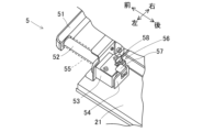
位置決め部5は、図8に示されるように台車本体20の荷台21の前部に設けられる。位置決め部5は、台車本体20を搬送目標に設けられた基準面に正対させる部位である。位置決め部5は、バンパー部51、支持部53、弾性部材55、および検出部56などで構成される。
5. Positioning unit 5
The positioning unit 5 is provided at the front of the platform 21 of the cart body 20 as shown in Fig. 8. The positioning unit 5 is a portion that faces the cart body 20 directly against a reference surface provided at the transport target. The positioning unit 5 is composed of a bumper unit 51, a support unit 53, an elastic member 55, a detection unit 56, and the like.

バンパー部51は、荷台21の前後方向の正面に設けられて左右方向に延在する(図2、6、7参照)。バンパー部51は、例えば、機械的強度が大きな金属や硬質樹脂などを用いて、水平配置される直線状の棒形状に形成される。バンパー部51の前面の両端には、面取りに類似する丸みが形成されている。The bumper section 51 is provided on the front of the loading platform 21 in the front-rear direction and extends in the left-right direction (see Figs. 2, 6, and 7). The bumper section 51 is formed in a horizontally arranged linear rod shape using, for example, metal or hard resin with high mechanical strength. Both ends of the front surface of the bumper section 51 are rounded, similar to chamfering.

バンパー部51は、荷台21の前端よりも後方に位置する。それでも、バンパー部51は、荷台21が搬送目標に衝突する以前に、搬送目標に設けられた基準面に当接する。このとき、バンパー部51は、左右方向に離隔した少なくとも二点で基準面に当接することが可能である。バンパー部51は、その後面の左側および右側の対称位置から後方に延びる左右一対の支持ロッド52をもつ。支持ロッド52として、例えば、金属や硬質樹脂などで形成された丸棒を用いることができる。The bumper portion 51 is located rearward of the front end of the loading platform 21. Even so, the bumper portion 51 abuts against a reference surface provided on the transport target before the loading platform 21 collides with the transport target. At this time, the bumper portion 51 can abut against the reference surface at at least two points spaced apart in the left-right direction. The bumper portion 51 has a pair of left and right support rods 52 that extend rearward from symmetrical positions on the left and right sides of its rear surface. The support rods 52 can be, for example, round bars made of metal or hard resin.

一方、台車本体20の荷台21の正面には、左右一対の支持部53が設けられる(図8参照)。支持部53は、前後方向に貫通する支持孔をもち、この支持孔を用いて支持ロッド52を前後方向に移動可能に支持する。換言すると、支持部53は、台車本体20に対してバンパー部51を前後方向に平行移動可能に支持する。支持ロッド52は、支持部53を突き抜けた後側に当て板54をもつ。当て板54は、支持孔の外径よりも大型に形成されており、支持ロッド52が支持部53から前側へ抜け出ることを防止する。On the other hand, a pair of left and right support parts 53 are provided on the front of the loading platform 21 of the trolley body 20 (see Figure 8). The support parts 53 have a support hole that penetrates in the front-rear direction, and support the support rod 52 so that it can move in the front-rear direction using this support hole. In other words, the support parts 53 support the bumper part 51 so that it can move parallel to the front-rear direction relative to the trolley body 20. The support rod 52 has a backing plate 54 on its rear side that passes through the support parts 53. The backing plate 54 is formed to be larger than the outer diameter of the support hole, and prevents the support rod 52 from slipping out of the support parts 53 to the front.

弾性部材55は、バンパー部51と支持部53の間に設けられ、支持ロッド52の外周面を取り囲む。弾性部材55には、円筒状のコイルばねが用いられる。弾性部材55は、前後方向に伸縮する弾性を有し、圧縮状態で組み付けられる。つまり、弾性部材55は、台車本体20に対してバンパー部51を前方に向けて付勢する。これにより、通常時に当て板54が支持部53に当接した状態が維持される。弾性部材55は、バンパー部51が基準面に当接するときにさらに圧縮されて、ショックを和らげる緩衝材の役割を果たす。The elastic member 55 is provided between the bumper portion 51 and the support portion 53, and surrounds the outer circumferential surface of the support rod 52. A cylindrical coil spring is used for the elastic member 55. The elastic member 55 has elasticity that allows it to expand and contract in the front-to-rear direction, and is assembled in a compressed state. In other words, the elastic member 55 biases the bumper portion 51 forward relative to the bogie body 20. This maintains the contact plate 54 in contact with the support portion 53 under normal conditions. The elastic member 55 is further compressed when the bumper portion 51 contacts the reference surface, and acts as a cushioning material that cushions shocks.

検出部56は、バンパー部51が基準面に当接したことを検出する。検出部56は、センサドッグ57および遮光検出センサ58などで構成される。センサドッグ57は、屈折された板材で形成されており、当て板54の後面に取り付けられる。センサドッグ57は、当て板54の後面から上方に延在し、さらに前側に屈折している。遮光検出センサ58は、支持部53の上側に設けられる。遮光検出センサ58は、上下方向に離隔する投光部および受光部を有し、上下方向に投射する検出光が遮光されているか否かを検出する。 The detection unit 56 detects when the bumper portion 51 abuts against a reference surface. The detection unit 56 is composed of a sensor dog 57 and a light-blocking detection sensor 58. The sensor dog 57 is formed of a bent plate material and is attached to the rear surface of the backing plate 54. The sensor dog 57 extends upward from the rear surface of the backing plate 54 and is further bent forward. The light-blocking detection sensor 58 is provided on the upper side of the support portion 53. The light-blocking detection sensor 58 has a light-emitting portion and a light-receiving portion spaced apart in the vertical direction, and detects whether the detection light projected in the vertical direction is blocked or not.

図8に示されるように、通常時に当て板54が支持部53に当接している状態において、センサドッグ57は、遮光検出センサ58の投光部と受光部の間に入り込む。したがって、遮光検出センサ58は、遮光状態を検出する。本実施形態において、遮光検出センサ58が検出する遮光状態は、バンパー部51が基準面に当接していないことを表す。8, when the contact plate 54 is in contact with the support portion 53 under normal circumstances, the sensor dog 57 enters between the light-emitting portion and the light-receiving portion of the light-blocking detection sensor 58. Therefore, the light-blocking detection sensor 58 detects the light-blocking state. In this embodiment, the light-blocking state detected by the light-blocking detection sensor 58 indicates that the bumper portion 51 is not in contact with the reference surface.

一方、台車2が牽引されてバンパー部51が基準面に当接するとき、搬送車3から台車2に走行駆動力が付与される。この走行駆動力により、バンパー部51が基準面に押し付けられ、弾性部材55が圧縮される。これにより、図9に示されるように、バンパー部51、支持ロッド52、当て板54、およびセンサドッグ57は、台車本体20に対して相対的に後退する。そしてこのとき、センサドッグ57は、遮光検出センサ58の投光部と受光部の間から抜け出る。したがって、遮光検出センサ58は、受光状態を検出する。本実施形態において、遮光検出センサ58が検出する受光状態は、バンパー部51が基準面に当接していることを表す。On the other hand, when the cart 2 is towed and the bumper portion 51 abuts against the reference surface, a driving force for travel is applied from the transport vehicle 3 to the cart 2. This driving force for travel presses the bumper portion 51 against the reference surface, compressing the elastic member 55. As a result, as shown in FIG. 9, the bumper portion 51, support rod 52, contact plate 54, and sensor dog 57 retreat relative to the cart body 20. At this time, the sensor dog 57 slips out from between the light-emitting portion and the light-receiving portion of the light-blocking detection sensor 58. Therefore, the light-blocking detection sensor 58 detects the light-receiving state. In this embodiment, the light-receiving state detected by the light-blocking detection sensor 58 indicates that the bumper portion 51 is abutting against the reference surface.

遮光検出センサ58は、検出結果を台車制御部に出力する。したがって、台車制御部は、バンパー部51が基準面に当接した状態を認識することができる。なお、上述したように、台車2は、バンパー部51の左右方向の対称位置に配置される二組の支持部53および弾性部材55を備える。これにより、台車本体20に対するバンパー部51の相対的な後退動作が円滑化される。また、検出部56は、左右一対の形態で設けられてバンパー部51の左右非対称動作に対応することが好ましいが、左右いずれか片側だけに簡略化されてもよい。The light blocking detection sensor 58 outputs the detection result to the trolley control unit. Therefore, the trolley control unit can recognize the state in which the bumper part 51 abuts against the reference surface. As described above, the trolley 2 has two sets of support parts 53 and elastic members 55 arranged at symmetrical positions in the left-right direction of the bumper part 51. This facilitates the relative retreat movement of the bumper part 51 with respect to the trolley body 20. In addition, it is preferable that the detection part 56 is provided in a pair on the left and right to correspond to the asymmetric movement of the bumper part 51, but it may be simplified to only one side, either the left or right.

6.収容装置8等
次に、搬送目標の一例である収容装置8について、図10および図11を参考にして説明する。収容装置8は、概ね直方体形状の装置であり、2個の搬送物Cを収容することができる。収容装置8は、第1収容位置81、第2収容位置82、基準面84、第1固定側通信部85、および第2固定側通信部86を有する。図10および図11において、台車2および搬送車3は、第2収容位置82の後方で基準面84に正対している。なお、「正対する」とは、台車2や搬送車3の中心線が基準面84に正確に直交することを指し示す。
6. Storage device 8, etc. Next, the storage device 8, which is an example of a transport target, will be described with reference to Figs. 10 and 11. The storage device 8 is a device having a roughly rectangular parallelepiped shape and can store two transport objects C. The storage device 8 has a first storage position 81, a second storage position 82, a reference surface 84, a first fixed side communication unit 85, and a second fixed side communication unit 86. In Figs. 10 and 11, the dolly 2 and the transport vehicle 3 face the reference surface 84 behind the second storage position 82. Note that "facing" refers to the center line of the dolly 2 and the transport vehicle 3 being exactly perpendicular to the reference surface 84.

第1収容位置81は、収容装置8の左側上部に区画されて後方に開口する直方体形状の収容空間が相当する。第2収容位置82は、収容装置8の右側上部に区画されて後方に開口する直方体形状の収容空間が相当する。第1収容位置81および第2収容位置82の内部の下側に、それぞれローラコンベア83が設けられる。ローラコンベア83は、台車2側の積み降ろし部6と概ね同じ高さに配置される。ローラコンベア83は、収容制御部(図略)から制御される駆動モータ(図略)により駆動される。ローラコンベア83は、積み降ろし部6と協調して動作し、搬送物Cを積み降ろしする。 The first storage position 81 corresponds to a rectangular parallelepiped storage space that is defined in the upper left part of the storage device 8 and opens to the rear. The second storage position 82 corresponds to a rectangular parallelepiped storage space that is defined in the upper right part of the storage device 8 and opens to the rear. A roller conveyor 83 is provided on the lower inside of each of the first storage position 81 and the second storage position 82. The roller conveyor 83 is positioned at approximately the same height as the loading/unloading section 6 on the trolley 2 side. The roller conveyor 83 is driven by a drive motor (not shown) controlled by a storage control section (not shown). The roller conveyor 83 operates in coordination with the loading/unloading section 6 to load and unload the transported item C.

基準面84は、第1収容位置81および第2収容位置82の後端よりも後方の下側に設けられる。基準面84は、台車2側のバンパー部51の高さを含んで鉛直方向に起立して配置され、かつ左右方向に長く延在する。基準面84が第1収容位置81および第2収容位置82よりも後方に設けられることにより、台車2の荷台21が第1収容位置81および第2収容位置82に到達する以前に、バンパー部51が基準面84に当接する。これにより、収容装置8と台車2の適正な位置関係が確保される。The reference surface 84 is provided below and behind the rear ends of the first storage position 81 and the second storage position 82. The reference surface 84 is arranged upright in the vertical direction, including the height of the bumper portion 51 on the trolley 2 side, and extends long in the left-right direction. By providing the reference surface 84 behind the first storage position 81 and the second storage position 82, the bumper portion 51 abuts against the reference surface 84 before the loading platform 21 of the trolley 2 reaches the first storage position 81 and the second storage position 82. This ensures an appropriate positional relationship between the storage device 8 and the trolley 2.

なお、基準面84に傾斜を設け、バンパー部51の前面にも傾斜を設けて、バンパー部51が基準面84に当接したときに、基準面84からバンパー部51に下向きの反力が作用するように構成してもよい。これによれば、台車2が前進してバンパー部51が基準面84に当接したときに、台車2が後退しにくくなる。 It is also possible to provide an inclination in the reference surface 84 and an inclination in the front surface of the bumper portion 51, so that when the bumper portion 51 abuts against the reference surface 84, a downward reaction force acts on the bumper portion 51 from the reference surface 84. In this way, when the cart 2 moves forward and the bumper portion 51 abuts against the reference surface 84, the cart 2 is less likely to move backward.

第1固定側通信部85は、基準面84の下側の左端付近の位置に、後向きに設けられる(図10、11参照)。第1固定側通信部85は、第1収容位置81に対応して、その下方に設けられたものである。第2固定側通信部86は、基準面84の下側の右端付近の位置に、後向きに設けられる(図11参照)。第2固定側通信部86は、第2収容位置82に対応して、その下方に設けられたものである。第1固定側通信部85および第2固定側通信部86は、収容制御部から制御される。なお、基準面84の下側の中央付近の位置は、図略の構造物が障害となり、固定側通信部を設けることができない。The first fixed side communication unit 85 is provided facing backwards at a position near the left end on the lower side of the reference surface 84 (see Figures 10 and 11). The first fixed side communication unit 85 is provided below the first storage position 81. The second fixed side communication unit 86 is provided facing backwards at a position near the right end on the lower side of the reference surface 84 (see Figure 11). The second fixed side communication unit 86 is provided below the second storage position 82. The first fixed side communication unit 85 and the second fixed side communication unit 86 are controlled by the storage control unit. Note that a fixed side communication unit cannot be provided near the center on the lower side of the reference surface 84 due to an obstruction caused by a structure (not shown).

一方、図6に示されるように、台車本体20(荷台21)には、第1可動側通信部71および第2可動側通信部72が設けられる。第1可動側通信部71は、台車本体20の前面の左寄りのバンパー部51よりも低い位置に、前向きに配置される。第2可動側通信部72は、台車本体20の前面の右寄りのバンパー部51よりも低い位置に、前向きに配置される。第1可動側通信部71および第2可動側通信部72は、台車制御部から制御される。 On the other hand, as shown in Figure 6, the trolley body 20 (cargo platform 21) is provided with a first movable side communication unit 71 and a second movable side communication unit 72. The first movable side communication unit 71 is arranged facing forward at a position lower than the bumper portion 51 on the left side of the front surface of the trolley body 20. The second movable side communication unit 72 is arranged facing forward at a position lower than the bumper portion 51 on the right side of the front surface of the trolley body 20. The first movable side communication unit 71 and the second movable side communication unit 72 are controlled by the trolley control unit.

図10および図11に示されるように、台車2が第2収容位置82の後方に位置するとき、第2固定側通信部86と第2可動側通信部72とが正対する。したがって、第2固定側通信部86および第2可動側通信部72は、基準面84に直交する方向に伝搬する光信号を用いた送受信が可能となる。これにより、第2可動側通信部72および台車制御部は、台車2が第2収容位置82の後方に位置すると確認することができる。一方、第2固定側通信部86および収容制御部は、第2収容位置82の後方に台車2が到着したと確認することができる。なお、このとき、第1固定側通信部85および第1可動側通信部71は、正対する通信相手が存在しない。10 and 11, when the trolley 2 is located behind the second storage position 82, the second fixed side communication unit 86 and the second movable side communication unit 72 face each other. Therefore, the second fixed side communication unit 86 and the second movable side communication unit 72 can transmit and receive using optical signals propagating in a direction perpendicular to the reference plane 84. This allows the second movable side communication unit 72 and the trolley control unit to confirm that the trolley 2 is located behind the second storage position 82. On the other hand, the second fixed side communication unit 86 and the storage control unit can confirm that the trolley 2 has arrived behind the second storage position 82. At this time, the first fixed side communication unit 85 and the first movable side communication unit 71 do not have a communication partner that they face each other with.

また、台車2が第1収容位置81の後方に位置するとき、第1固定側通信部85と第1可動側通信部71とが正対する。したがって、第1固定側通信部85および第1可動側通信部71は、基準面84に直交する方向に伝搬する光信号を用いた送受信が可能となる。これにより、第1可動側通信部71および台車制御部は、台車2が第1収容位置81の後方に位置すると確認することができる。一方、第1固定側通信部85および収容制御部は、第1収容位置81の後方に台車2が到着したと確認することができる。なお、このとき、第2固定側通信部86および第2可動側通信部72は、正対する通信相手が存在しない。 When the trolley 2 is located behind the first storage position 81, the first fixed side communication unit 85 and the first movable side communication unit 71 face each other. Therefore, the first fixed side communication unit 85 and the first movable side communication unit 71 can transmit and receive using optical signals propagating in a direction perpendicular to the reference plane 84. This allows the first movable side communication unit 71 and the trolley control unit to confirm that the trolley 2 is located behind the first storage position 81. On the other hand, the first fixed side communication unit 85 and the storage control unit can confirm that the trolley 2 has arrived behind the first storage position 81. At this time, the second fixed side communication unit 86 and the second movable side communication unit 72 have no communication partner to face.

光信号を用いた確認により、収容制御部および台車制御部は、台車2の到着位置および到着時期を正確かつ迅速に確認することができる。これにより、収容制御部は、2組のローラコンベア83のうち台車2が到着した側を間違いなく動作させることができる。加えて、収容制御部および台車制御部の協調制御により、ローラコンベア83と積み降ろし部6とが協調して動作するので、効率的に搬送物Cを積み降ろしすることができる。 By using optical signals to confirm, the storage control unit and the trolley control unit can accurately and quickly confirm the arrival position and arrival time of the trolley 2. This allows the storage control unit to operate the side of the two sets of roller conveyors 83 where the trolley 2 has arrived without fail. In addition, the roller conveyors 83 and the loading/unloading unit 6 operate in coordination through cooperative control by the storage control unit and the trolley control unit, allowing the transported goods C to be loaded and unloaded efficiently.

仮に、障害となる構造物が無く、図11に破線で示されるように第2固定側通信部86を基準面84の下側の中央付近の位置に設けることができる場合、第2可動側通信部72を省略することができる。この態様では、第1可動側通信部71に対して第1固定側通信部85が通信可能である場合に、台車2が第1収容位置81の後方に位置したと確認することができ、第1可動側通信部71に対して第2固定側通信部86が通信可能である場合に、台車2が第2収容位置82の後方に位置したと確認することができる。 If there are no obstructing structures and the second fixed side communication unit 86 can be provided near the center of the lower side of the reference plane 84 as shown by the dashed line in Fig. 11, the second movable side communication unit 72 can be omitted. In this embodiment, when the first fixed side communication unit 85 can communicate with the first movable side communication unit 71, it can be confirmed that the trolley 2 is located behind the first storage position 81, and when the second fixed side communication unit 86 can communicate with the first movable side communication unit 71, it can be confirmed that the trolley 2 is located behind the second storage position 82.

7.搬送装置1および台車2の動作、作用
次に、搬送装置1および台車2の動作、作用について、台車2が収容装置8まで移動して停止する場合を例にして説明する。この場合、搬送車3は、連結部4によって連結された台車2を牽引しながら経路表示テープ3Aに沿って走行し、収容装置8の基準面84に正対する方向から接近する。この時点で、台車2の左右方向の位置が定まっており以降は変化しない。
また、搬送車3は、基準面84に接近した後に走行駆動力を一定にして、一定速度でバンパー部51を基準面84に当接させる。このときの一定速度は、搬送車3の通常時の走行速度でもよいし、それよりも低速度であってもよい。バンパー部51が基準面84に当接するとき、台車2は、いつも搬送車3と同じ姿勢(向き)であるとは限らず、換言すると、台車2は、基準面84に正対しているとは限らない。
7. Operation and Function of the Conveying Device 1 and the Carriage 2 Next, the operation and function of the conveying device 1 and the carriage 2 will be described using as an example a case where the carriage 2 moves to the storage device 8 and stops there. In this case, the conveying vehicle 3 travels along the route display tape 3A while pulling the carriage 2 connected by the connector 4, and approaches the storage device 8 from a direction directly facing the reference surface 84. At this point, the left-right position of the carriage 2 is determined and does not change thereafter.
In addition, after approaching the reference surface 84, the transport vehicle 3 makes the traveling drive force constant and abuts the bumper portion 51 against the reference surface 84 at a constant speed. The constant speed at this time may be the normal traveling speed of the transport vehicle 3 or may be a speed slower than that. When the bumper portion 51 abuts against the reference surface 84, the cart 2 is not always in the same posture (orientation) as the transport vehicle 3; in other words, the cart 2 is not always facing the reference surface 84.

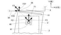
例えば、図12に示される例では、台車2の姿勢が搬送車3に対して右向きに傾いており、台車2の左側が前方に出ている。ここで、図12の右上の矢印に示されるように、搬送車3の右方向をX軸方向とし、前方向をY軸方向とする。この場合、基準面84は、X軸に平行して延在する。また、図12において、台車2の姿勢の自動修正の作用を見易く説明するために、台車2の姿勢の傾きが誇張して描かれている。For example, in the example shown in Figure 12, the attitude of the trolley 2 is tilted to the right relative to the transport vehicle 3, and the left side of the trolley 2 is protruding forward. Here, as shown by the arrow in the upper right corner of Figure 12, the right direction of the transport vehicle 3 is the X-axis direction, and the forward direction is the Y-axis direction. In this case, the reference plane 84 extends parallel to the X-axis. Also, in Figure 12, the tilt of the attitude of the trolley 2 is exaggerated to easily explain the action of automatic correction of the attitude of the trolley 2.

図示されるように、台車2が搬送車3に対して右向きに傾いた姿勢の場合、バンパー部51の左前端59が基準面84に最初に当接する。このとき、搬送車3の前側連結ピン41が台車2の前側係止部材46を押動する走行駆動力F1は、台車本体20から弾性部材55を介してバンパー部51に作用する。この走行駆動力F1は、左前端59に向かう斜め左前方向の分力F2と、斜め右前方向に向かう分力F3とに分けて考えることができる。さらに、分力F2は、Y軸方向の分力F2Yと、X軸マイナス方向の分力F2Xとに分けて考えることができる。As shown in the figure, when the trolley 2 is tilted to the right relative to the transport vehicle 3, the left front end 59 of the bumper portion 51 first abuts against the reference surface 84. At this time, the traveling drive force F1, which causes the front connecting pin 41 of the transport vehicle 3 to push the front locking member 46 of the trolley 2, acts on the bumper portion 51 from the trolley body 20 via the elastic member 55. This traveling drive force F1 can be considered to be divided into a component force F2 in the diagonally left front direction toward the left front end 59, and a component force F3 in the diagonally right front direction. Furthermore, the component force F2 can be considered to be divided into a component force F2Y in the Y-axis direction and a component force F2X in the negative X-axis direction.

分力F2Yは、基準面84からの反力と釣り合って相殺される。分力F2Xの作用により、バンパー部51の左前端59は、基準面84に摺接しながら左方に移動する。一方、分力F3のX軸方向成分は、前車輪24および後車輪25の接地摩擦抵抗と釣り合って相殺される。また、分力F3のY軸方向成分の作用により、台車2は、Y軸方向に駆動される。したがって、台車2は、バンパー部51の左前端59が左方に移動しながら、X軸方向(左右方向)に移動せずにY軸方向に前進する。 The force component F2Y is balanced and cancelled out by the reaction force from the reference surface 84. Due to the action of the force component F2X, the left front end 59 of the bumper portion 51 moves to the left while sliding against the reference surface 84. Meanwhile, the X-axis component of the force component F3 is balanced and cancelled out by the ground friction resistance of the front wheels 24 and rear wheels 25. Furthermore, the trolley 2 is driven in the Y-axis direction due to the action of the Y-axis component of the force component F3. Therefore, while the left front end 59 of the bumper portion 51 moves to the left, the trolley 2 advances in the Y-axis direction without moving in the X-axis direction (left-right direction).

これにより、台車2は、前側連結ピン41を回転中心として図12の反時計回りに徐々に姿勢が変化して、搬送車3に平行する姿勢へと自動的に修正されてゆく。この結果、台車2は、搬送車3に平行する姿勢となり、バンパー部51の左前端59および右前端を含む前面の全体が基準面84に当接する。つまり、台車2は、バンパー部51が基準面84に対して左右方向に離隔した少なくとも二点で当接することにより、基準面84に対して台車本体20を正対させることができる。したがって、台車2は、基準面84に正対する。12 around the front connecting pin 41 as the center of rotation, and is automatically corrected to a position parallel to the transport vehicle 3. As a result, the trolley 2 assumes a position parallel to the transport vehicle 3, and the entire front surface, including the left front end 59 and right front end of the bumper portion 51, abuts against the reference surface 84. In other words, the trolley 2 can have the trolley body 20 directly facing the reference surface 84 by having the bumper portion 51 abut against the reference surface 84 at least at two points spaced apart in the left-right direction. Therefore, the trolley 2 faces the reference surface 84 directly.

さらに、台車2の前進に伴い、弾性部材55が圧縮される。最終的に、搬送車3からの走行駆動力F1と、弾性部材55の圧縮による反力とが釣り合う状態で、台車2および搬送車3が所定位置に停止する。この停止状態は、検出部56の遮光検出センサ58によって検出され、台車制御部によって認識される。Furthermore, as the trolley 2 moves forward, the elastic member 55 is compressed. Eventually, the trolley 2 and the transport vehicle 3 stop at a predetermined position when the driving force F1 from the transport vehicle 3 and the reaction force caused by the compression of the elastic member 55 are balanced. This stopped state is detected by the light blocking detection sensor 58 of the detection unit 56 and recognized by the trolley control unit.

ここで、毎回の停止時に走行駆動力F1を一定とするので、バンパー部51は、弾性部材55によって所定の押し付け力で基準面84に押し付けられることになる。これによれば、弾性部材55の圧縮量が一定となり、台車2の前後方向の停止位置が安定化される。以上説明したように、台車2を基準面84に対して正対させることができ、さらに、台車2の停止位置を安定化することができる。 Here, since the driving force F1 is constant each time the vehicle stops, the bumper portion 51 is pressed against the reference surface 84 with a predetermined pressing force by the elastic member 55. This makes the compression amount of the elastic member 55 constant, and stabilizes the stopping position of the trolley 2 in the fore-and-aft direction. As described above, the trolley 2 can be made to face the reference surface 84 directly, and further, the stopping position of the trolley 2 can be stabilized.

なお、走行駆動力F1を大きめの一定値に設定すると、台車2が停止する所定位置は基準面84に近づき、走行駆動力F1を小さめの一定値に設定すると、所定位置は基準面84から遠ざかる。また、バンパー部51が基準面84に当接するときのショックの大小は、走行駆動力F1に依存して変化する。このため、走行駆動力F1の大きさは、搬送目標の種類や形状、搬送物Cの耐ショック性能などに基づいて、適正な一定値に設定される。 When the driving force F1 is set to a large constant value, the predetermined position where the trolley 2 stops approaches the reference surface 84, and when the driving force F1 is set to a small constant value, the predetermined position moves away from the reference surface 84. The magnitude of the shock when the bumper portion 51 abuts against the reference surface 84 varies depending on the driving force F1. For this reason, the magnitude of the driving force F1 is set to an appropriate constant value based on the type and shape of the transport target, the shock resistance of the transported item C, etc.

実施形態の台車2や搬送装置1において、台車本体20は、連結された搬送車3に対して左右方向の位置が位置決めされるが、搬送車3に対する姿勢(向き)が変化し得る。それでも、台車2が搬送車3に牽引されて収容装置8まで移動するときに、バンパー部51の左右方向に離隔した少なくとも二点が基準面84に対して当接することにより、台車本体20は、前後方向の所定位置に位置決めされ、かつ基準面84に対して正対する姿勢となる。したがって、台車2が停止するときの位置および姿勢を高い精度で管理することができる。In the embodiment of the trolley 2 and transport device 1, the trolley body 20 is positioned in the left-right direction relative to the connected transport vehicle 3, but the attitude (orientation) relative to the transport vehicle 3 can change. Even so, when the trolley 2 is towed by the transport vehicle 3 and moves to the storage device 8, at least two points spaced apart in the left-right direction of the bumper portion 51 abut against the reference surface 84, so that the trolley body 20 is positioned at a predetermined position in the front-rear direction and is oriented directly facing the reference surface 84. Therefore, the position and attitude of the trolley 2 when it stops can be managed with high precision.

8.応用例のバンパー部5A
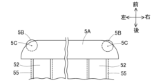
次に、応用例のバンパー部5Aについて、図13を参考にして説明する。応用例のバンパー部5Aは、そのサイズが実施形態のバンパー部51と同程度であり、2個のコロ部材5Bをもつ点が実施形態と相違する。コロ部材5Bは、バンパー部5Aの左前端の位置および右前端の位置にそれぞれ配置される。
8. Bumper part 5A of application example
Next, the bumper portion 5A of the application example will be described with reference to Fig. 13. The bumper portion 5A of the application example is approximately the same in size as the bumper portion 51 of the embodiment, but differs from the embodiment in that it has two roller members 5B. The roller members 5B are disposed at the left front end and the right front end of the bumper portion 5A.

コロ部材5Bは、鉛直軸5Cを中心とする円柱形状または円筒形状に形成される。かつコロ部材5Bは、鉛直軸5Cの周りに自転自在となるようにバンパー部5Aに取り付けられる。コロ部材5Bの一部分は、バンパー部5Aの左前端の外面および右前端の外面から前方に突出しており、基準面84に当接可能となっている。The roller member 5B is formed in a columnar or cylindrical shape centered on the vertical axis 5C. The roller member 5B is attached to the bumper portion 5A so as to be rotatable about the vertical axis 5C. A portion of the roller member 5B protrudes forward from the outer surface of the left front end and the outer surface of the right front end of the bumper portion 5A and is capable of abutting against the reference surface 84.

応用例において、図12を用いて説明した台車2の姿勢の自動修正の作用が、同様に発生する。また、バンパー部5Aは、基準面84に沿って左右方向に移動する場合に、コロ部材5Bが基準面84に接する。このため、バンパー部5Aの左右方向の移動に際して、摺動摩擦抵抗よりも小さな転がり摩擦抵抗で済むため、円滑な移動が可能となる。この結果、台車2の姿勢の自動修正の作用は、より確実なものとなる。In the application example, the action of automatically correcting the posture of the trolley 2 described using Figure 12 occurs in the same manner. Furthermore, when the bumper portion 5A moves in the left-right direction along the reference surface 84, the roller members 5B come into contact with the reference surface 84. Therefore, when the bumper portion 5A moves in the left-right direction, the rolling friction resistance is smaller than the sliding friction resistance, allowing for smooth movement. As a result, the action of automatically correcting the posture of the trolley 2 becomes more reliable.

9.変形例の位置決め部
変形例の位置決め部では、バンパー部51またはバンパー部5Aを用い、支持ロッド52の後端を直接的に台車本体20に固定する。この変形に伴い、支持部53、当て板54、弾性部材55、および検出部56は省略される。変形例では、弾性部材55が省略されるため、バンパー部51が基準面84に当接するときのショックに起因する台車2の位置ずれおよび姿勢変化の懸念に対して対策を行う。
9. Positioning Section of Modified Example In the positioning section of the modified example, the bumper section 51 or the bumper section 5A is used, and the rear end of the support rod 52 is directly fixed to the cart body 20. With this modification, the support section 53, the contact plate 54, the elastic member 55, and the detection section 56 are omitted. Since the elastic member 55 is omitted in the modified example, measures are taken to address concerns about misalignment and change in attitude of the cart 2 caused by the shock when the bumper section 51 abuts against the reference surface 84.

具体的には、搬送車3は、台車2を牽引して収容装置8まで移動させるときに、基準面84に正対する方向から減速しつつ接近して、通常時の走行速度よりも低速度でバンパー部(51、5A)を基準面84に当接させる。これにより、前記したショックを軽減して、前記した懸念を解消することができる。Specifically, when the transport vehicle 3 tows the cart 2 to the storage device 8, it approaches the reference surface 84 from a direction directly facing the reference surface 84 while decelerating, and abuts the bumper portion (51, 5A) against the reference surface 84 at a speed slower than the normal traveling speed. This reduces the shock and eliminates the above-mentioned concerns.

変形例において、図12を用いて説明した台車2の姿勢の自動修正の作用が、同様に発生する。また、省略された弾性部材55の圧縮量を考慮する必要が無いため、搬送車3は、毎回の停止時に低速度であればよく、一定速度とする必要がない。それでも、バンパー部(51、5A)の左右方向に離隔した少なくとも二点が基準面84に当接した状態で台車2が停止するので、台車2の停止位置および停止姿勢が安定化される。In the modified example, the action of automatically correcting the posture of the trolley 2 described with reference to Fig. 12 occurs in the same way. Also, since there is no need to consider the amount of compression of the omitted elastic member 55, the transport vehicle 3 only needs to move at a low speed each time it stops, and does not need to move at a constant speed. Nevertheless, the trolley 2 stops with at least two points of the bumper portion (51, 5A) spaced apart in the left-right direction abutting the reference surface 84, so the stopping position and stopping posture of the trolley 2 are stabilized.

10.実施形態の変形および応用
なお、バンパー部(51、5A)は、実施形態で説明した直線状の棒形状に限定されない。例えば、バンパー部は、左前端および右前端が前方に突出して中央部分が後方にへこんだ曲線形状でもよく、あるいは、左右に分離された分離型であってもよい。また、バンパー部(51、5A)を含む位置決め部5の構成は、搬送車3の後側や前側に連結される台車に適用することが可能である。
10. Modifications and Applications of the Embodiments The bumper portion (51, 5A) is not limited to the straight rod shape described in the embodiment. For example, the bumper portion may be a curved shape with the left and right front ends protruding forward and the center portion recessed backward, or may be a separate type separated into left and right. In addition, the configuration of the positioning portion 5 including the bumper portion (51, 5A) can be applied to a cart connected to the rear or front of the transport vehicle 3.

さらに、連結部4を構成する前側連結ピン41および後側連結ピン42を台車2側に設け、前側係止部材46および切換機構4Aを搬送車3側に設けてもよい。また、搬送車3の走行経路は、経路表示テープ3A以外により定められてもよい。また、第1可動側通信部71および第2可動側通信部72は、台車2でなく搬送車3に設けられてもよい。実施形態は、他にも様々な変形や応用が可能である。 Furthermore, the front connecting pin 41 and the rear connecting pin 42 constituting the connecting portion 4 may be provided on the trolley 2 side, and the front engaging member 46 and the switching mechanism 4A may be provided on the transport vehicle 3 side. The travel route of the transport vehicle 3 may also be determined by something other than the route display tape 3A. The first movable side communication unit 71 and the second movable side communication unit 72 may also be provided on the transport vehicle 3 instead of the trolley 2. Various other modifications and applications of the embodiment are possible.

1:搬送装置 2:台車 20:台車本体 21:荷台 24:前車輪 25:後車輪 27:受電コネクタ 3:搬送車 31:車両本体 32:駆動車輪 37:給電コネクタ 4:連結部 41:前側連結ピン 42:後側連結ピン 45:底板 46:前側係止部材 48:クランク縁部 4A:切換機構 4C:後側係止部材 5:位置決め部 51:バンパー部 53:支持部 55:弾性部材 56:検出部 57:センサドッグ 58:遮光検出センサ 5A:バンパー部 5B:コロ部材 6:積み降ろし部 71:第1可動側通信部 72:第2可動側通信部 8:収容装置 84:基準面 85:第1固定側通信部 86:第2固定側通信部 C:搬送物 1: Transport device 2: Cart 20: Cart body 21: Loading platform 24: Front wheels 25: Rear wheels 27: Power receiving connector 3: Transport vehicle 31: Vehicle body 32: Drive wheels 37: Power supply connector 4: Connection section 41: Front connecting pin 42: Rear connecting pin 45: Bottom plate 46: Front locking member 48: Crank edge section 4A: Switching mechanism 4C: Rear locking member 5: Positioning section 51: Bumper section 53: Support section 55: Elastic member 56: Detection section 57: Sensor dog 58: Shading detection sensor 5A: Bumper section 5B: Roller member 6: Loading/unloading section 71: First movable side communication section 72: Second movable side communication section 8: Storage device 84: Reference surface 85: First fixed side communication section 86: Second fixed side communication section C: Transported goods

Claims (15)

搬送物を載せる荷台および走行用の車輪を有する台車本体と、
前記台車本体の下側に進入した状態の搬送車に対して前記台車本体の左右方向の位置を位置決めするとともに、前記搬送車に対する前記台車本体の姿勢変化を許容しつつ、前記搬送車に対して前記台車本体を牽引可能に連結する連結部と、
前記台車本体の前後方向の正面に設けられ、前記台車本体が前記搬送車に牽引されて搬送目標まで移動するときに、前記搬送目標に設けられた基準面に対して左右方向に離隔した少なくとも二点で当接することにより、前後方向の所定位置に前記台車本体を位置決めするとともに、前記基準面に対して前記台車本体を正対させるバンパー部と、
を備える台車。
A carriage body having a platform for carrying an object to be transported and wheels for traveling;
a coupling section that determines a left-right position of the carriage body with respect to the transport vehicle that has entered under the carriage body and couples the carriage body to the transport vehicle so as to be towable while allowing a change in posture of the carriage body with respect to the transport vehicle;
a bumper section that is provided on a front side of the carriage body in a front-rear direction, and that, when the carriage body is towed by the transport vehicle and moves to a transport target, contacts with a reference surface provided on the transport target at at least two points spaced apart in the left-right direction, thereby positioning the carriage body at a predetermined position in the front-rear direction and facing the carriage body directly relative to the reference surface;
A trolley equipped with:
前記台車本体に対して前記バンパー部を前後方向に平行移動可能に支持する支持部と、
前記台車本体に対して前記バンパー部を前方に向けて付勢する弾性部材と、を備える、請求項1に記載の台車。
A support portion that supports the bumper portion so as to be movable in parallel in a front-rear direction relative to the carriage body;
The bogie according to claim 1 , further comprising: an elastic member that biases the bumper portion forward relative to the bogie body.
前記バンパー部の左右方向の対称位置に配置される複数組の前記支持部および前記弾性部材を備える、請求項2に記載の台車。 The bogie according to claim 2, comprising multiple sets of the support parts and the elastic members arranged at symmetrical positions in the left-right direction of the bumper part. 前記バンパー部は、前記搬送車が前記台車本体を牽引して前記搬送目標まで移動したときに、前記弾性部材によって所定の押し付け力で前記基準面に押し付けられる、請求項2または3に記載の台車。 The cart according to claim 2 or 3, wherein the bumper portion is pressed against the reference surface with a predetermined pressing force by the elastic member when the transport vehicle tows the cart body and moves to the transport target. 前記バンパー部が前記基準面に当接したことを検出する検出部を備える、請求項1~4のいずれか一項に記載の台車。 The bogie according to any one of claims 1 to 4, further comprising a detection unit that detects when the bumper portion abuts against the reference surface. 搬送物を載せる荷台および走行用の車輪を有する台車本体と、
搬送車に対して前記台車本体を牽引可能に連結する連結部と、
前記台車本体に設けられ、搬送目標に設けられた基準面に当接可能なバンパー部と、
前記バンパー部が前記基準面に当接したことを検出する検出部と、を備え
前記バンパー部は、自転自在であって前記基準面に当接可能なコロ部材をもつ、
台車。
A carriage body having a platform for carrying an object to be transported and wheels for traveling;
A coupling portion that couples the carriage body to a transport vehicle so as to be towable;
A bumper portion provided on the carriage body and capable of contacting a reference surface provided on a conveyance target;
a detection unit that detects when the bumper portion abuts on the reference surface ,
The bumper portion has a roller member that is rotatable and can contact the reference surface.
Trolley.
前記連結部は、
前記台車本体の下面および前記搬送車の上面の一方に垂直に設けられた連結ピンと、
前記台車本体の前記下面および前記搬送車の前記上面の他方に設けられ、左右方向および前後方向の少なくとも一方向において、所定の遊び寸法の範囲内で前記連結ピンを相対移動可能に係止する係止部材と、を有して、
前記搬送車に対する前記台車本体の水平方向の姿勢変化を許容する、
請求項1~のいずれか一項に記載の台車。
The connecting portion is
A connecting pin provided vertically on one of the lower surface of the carriage body and the upper surface of the transport vehicle;
a locking member provided on the other of the lower surface of the carriage body and the upper surface of the transport vehicle, and locking the connecting pin so as to be relatively movable within a range of a predetermined play dimension in at least one of a left-right direction and a front-rear direction,
Allowing a change in the horizontal attitude of the carriage body relative to the transport vehicle;
The cart according to any one of claims 1 to 6 .
前記係止部材を係止位置と非係止位置とに切換える切換機構を有し、
前記係止部材が前記係止位置にあるときは、前記台車本体の下側からの前記搬送車の退出を許容せず、前記係止部材が前記非係止位置にあるときは、前記台車本体の下側からの前記搬送車の退出を許容する、請求項に記載の台車。
A switching mechanism is provided for switching the locking member between a locking position and a non-locking position,
A trolley as described in claim 7, wherein when the locking member is in the locking position, it does not allow the transport vehicle to exit from under the trolley body, and when the locking member is in the non-locking position , it allows the transport vehicle to exit from under the trolley body.
前記連結部は、前記搬送車に対する前記台車本体の鉛直方向の姿勢変化を許容する、請求項1~のいずれか一項に記載の台車。 The cart according to any one of claims 1 to 8 , wherein the coupling portion allows a change in the vertical attitude of the cart body relative to the transport vehicle. 搬送物を載せる荷台および走行用の車輪を有する台車本体と、
搬送車に対して前記台車本体を牽引可能に連結する連結部と、
前記台車本体に設けられ、搬送目標に設けられた基準面に当接可能なバンパー部と、
前記バンパー部が前記基準面に当接したことを検出する検出部と、を備え
前記荷台は、
前記搬送物を正面から前後方向に積み降ろしする積み降ろし部と、
前記搬送車の給電コネクタに嵌合して、前記積み降ろし部を駆動する電力を受け取る受電コネクタと、を有する、
台車。
A carriage body having a platform for carrying an object to be transported and wheels for traveling;
A coupling portion that couples the carriage body to a transport vehicle so as to be towable;
A bumper portion provided on the carriage body and capable of contacting a reference surface provided on a conveyance target;
a detection unit that detects when the bumper portion abuts on the reference surface ,
The loading platform is:
A loading and unloading unit that loads and unloads the transported object from the front in a front-rear direction;
a power receiving connector that is fitted into a power supply connector of the transport vehicle to receive power for driving the loading/unloading unit,
Trolley.
前記台車本体に設けられ、前記搬送目標に設けられた固定側通信部と正対して通信を行う可動側通信部を備える、請求項1~10のいずれか一項に記載の台車。 The cart according to any one of claims 1 to 10 , further comprising a movable side communication unit provided on the cart body, facing directly to a fixed side communication unit provided on the transport target and communicating with the fixed side communication unit. 前記搬送目標は、前記搬送物を収容する複数の収容位置、および前記収容位置の各々に対応して設けられた複数の前記固定側通信部を備え、
前記可動側通信部は、いずれかの前記固定側通信部に正対して通信が可能となることにより、前記台車本体が正対する前記収容位置を確認する、
請求項11に記載の台車。
the transport target includes a plurality of storage positions for storing the transported object, and a plurality of the fixed-side communication units provided corresponding to each of the storage positions;
The movable-side communication unit is capable of communicating with any one of the fixed-side communication units to confirm the storage position to which the carriage body faces.
12. The dolly according to claim 11 .
前記可動側通信部および前記固定側通信部は、前記基準面に交差する方向に伝搬する光信号を送受信する、請求項11または12に記載の台車。 The dolly according to claim 11 or 12 , wherein the movable-side communication unit and the fixed-side communication unit transmit and receive optical signals propagating in a direction intersecting the reference plane. 請求項1~1のいずれか一項に記載された台車と、
前記台車本体の下側に進入可能な前記搬送車と、
を備える搬送装置。
A dolly according to any one of claims 1 to 13 ;
The transport vehicle capable of entering under the carriage body;
A conveying device comprising:
前記搬送車は、前記台車を牽引して前記搬送目標まで移動させるときに、前記基準面に正対する方向から減速しつつ接近して、通常時の走行速度よりも低速度で前記バンパー部を前記基準面に当接させる、請求項14に記載の搬送装置。
The transport device described in claim 14, wherein when the transport vehicle tows the cart to move it to the transport target, the transport vehicle approaches the reference surface from a direction directly facing the reference surface while decelerating, and abuts the bumper portion against the reference surface at a speed slower than the normal traveling speed.
JP2023546671A 2021-09-10 2021-09-10 Carts and transport devices Active JP7635404B2 (en)

Applications Claiming Priority (1)

Application Number Priority Date Filing Date Title
PCT/JP2021/033326 WO2023037498A1 (en) 2021-09-10 2021-09-10 Cart and transport device

Publications (2)

Publication Number Publication Date
JPWO2023037498A1 JPWO2023037498A1 (en) 2023-03-16
JP7635404B2 true JP7635404B2 (en) 2025-02-25

Family

ID=85506180

Family Applications (1)

Application Number Title Priority Date Filing Date
JP2023546671A Active JP7635404B2 (en) 2021-09-10 2021-09-10 Carts and transport devices

Country Status (5)

Country Link
US (1) US20240375923A1 (en)
JP (1) JP7635404B2 (en)
CN (1) CN117751081A (en)
DE (1) DE112021008220T5 (en)
WO (1) WO2023037498A1 (en)

Families Citing this family (5)

* Cited by examiner, † Cited by third party
Publication number Priority date Publication date Assignee Title
WO2025088664A1 (en) * 2023-10-23 2025-05-01 株式会社Fuji Conveyance device
WO2025109651A1 (en) * 2023-11-20 2025-05-30 ヤマハ発動機株式会社 Work device, work target device, work system, and method for adjusting position of working part with respect to work target device
WO2025115165A1 (en) * 2023-11-30 2025-06-05 株式会社Fuji Automatic conveyance device and automatic conveyance system
WO2025169377A1 (en) * 2024-02-08 2025-08-14 株式会社Fuji Attaching/detaching mechanism and article-transporting device
CN119953763B (en) * 2025-03-17 2025-12-16 中车长江运输设备集团有限公司 Cargo delivery methods, unmanned transport vehicles and storage media

Citations (3)

* Cited by examiner, † Cited by third party
Publication number Priority date Publication date Assignee Title
WO2017090108A1 (en) 2015-11-25 2017-06-01 株式会社日立製作所 Shelf arrangement system, conveyance robot, and shelf arrangement method
JP2019091770A (en) 2017-11-13 2019-06-13 Juki株式会社 Component transfer device
WO2021144866A1 (en) 2020-01-14 2021-07-22 株式会社Fuji Article transport system

Family Cites Families (7)

* Cited by examiner, † Cited by third party
Publication number Priority date Publication date Assignee Title
JP2798307B2 (en) * 1990-12-11 1998-09-17 日本輸送機株式会社 Stop positioning guidance device for automatic guided vehicles
JPH05265551A (en) * 1992-03-23 1993-10-15 Suzuki Motor Corp Carrying device
JP2933154B2 (en) * 1994-09-21 1999-08-09 株式会社椿本チエイン Traveling car bumper device
JP2682970B2 (en) * 1995-06-30 1997-11-26 川崎重工業株式会社 Bumper device for carrier truck
JP5132471B2 (en) * 2008-08-01 2013-01-30 矢崎化工株式会社 Automatic connection device for transport cart and automatic guided vehicle
JP6888819B2 (en) * 2016-07-29 2021-06-16 日本電産シンポ株式会社 Automated guided vehicle and automatic guided vehicle control method
CN211844692U (en) * 2020-04-09 2020-11-03 杨雨航 AGV intelligence commodity circulation dolly

Patent Citations (3)

* Cited by examiner, † Cited by third party
Publication number Priority date Publication date Assignee Title
WO2017090108A1 (en) 2015-11-25 2017-06-01 株式会社日立製作所 Shelf arrangement system, conveyance robot, and shelf arrangement method
JP2019091770A (en) 2017-11-13 2019-06-13 Juki株式会社 Component transfer device
WO2021144866A1 (en) 2020-01-14 2021-07-22 株式会社Fuji Article transport system

Also Published As

Publication number Publication date
JPWO2023037498A1 (en) 2023-03-16
CN117751081A (en) 2024-03-22
US20240375923A1 (en) 2024-11-14
WO2023037498A1 (en) 2023-03-16
DE112021008220T5 (en) 2024-07-18

Similar Documents

Publication Publication Date Title
JP7635404B2 (en) Carts and transport devices
US11820596B2 (en) Automated storage and retrieval system
JP4813409B2 (en) Trailer
US9327903B2 (en) Suspension system for autonomous transports
KR101395752B1 (en) Arrangement for storage, warehouse rack and handling machine particularly for such arrangement
KR20070033972A (en) Automated loading system and method
US12187337B2 (en) Conveyance system and conveyance method
CN217498014U (en) Loading and unloading vehicle system
CN116002266A (en) Warehouse system, picking and placing method and robot
WO2024139910A1 (en) Robot and warehousing system
CN114955594B (en) Loading and unloading vehicle system
US20250332874A1 (en) Mechanically-adaptable hitch guide
JP2026003098A (en) Roller device
CN218987713U (en) Robot and warehousing system
JP2023014790A (en) traction jig
WO2025141648A1 (en) Unmanned transport vehicle
EP3562763B1 (en) Automated storage and retrieval system
JP7279663B2 (en) Bogie connection system
CN211846097U (en) logistics robot
CN217497386U (en) Loading and unloading robot
JP6070074B2 (en) Stopper device and automatic warehouse
JP5365604B2 (en) Article supply / discharge device
JP7491253B2 (en) Box delivery mechanism and box delivery system
JP7538178B2 (en) Loading and unloading vehicle
US20250313406A1 (en) Assembly for an automated storage and retrieval system

Legal Events

Date Code Title Description
A621 Written request for application examination

Free format text: JAPANESE INTERMEDIATE CODE: A621

Effective date: 20240118

A131 Notification of reasons for refusal

Free format text: JAPANESE INTERMEDIATE CODE: A131

Effective date: 20240820

A601 Written request for extension of time

Free format text: JAPANESE INTERMEDIATE CODE: A601

Effective date: 20241008

A521 Request for written amendment filed

Free format text: JAPANESE INTERMEDIATE CODE: A523

Effective date: 20241216

TRDD Decision of grant or rejection written
A01 Written decision to grant a patent or to grant a registration (utility model)

Free format text: JAPANESE INTERMEDIATE CODE: A01

Effective date: 20250128

A61 First payment of annual fees (during grant procedure)

Free format text: JAPANESE INTERMEDIATE CODE: A61

Effective date: 20250212

R150 Certificate of patent or registration of utility model

Ref document number: 7635404

Country of ref document: JP

Free format text: JAPANESE INTERMEDIATE CODE: R150