JP7635296B2 - Improved microporous membranes, separators and lithium batteries - Google Patents
Improved microporous membranes, separators and lithium batteries Download PDFInfo
- Publication number
- JP7635296B2 JP7635296B2 JP2023074683A JP2023074683A JP7635296B2 JP 7635296 B2 JP7635296 B2 JP 7635296B2 JP 2023074683 A JP2023074683 A JP 2023074683A JP 2023074683 A JP2023074683 A JP 2023074683A JP 7635296 B2 JP7635296 B2 JP 7635296B2
- Authority
- JP
- Japan
- Prior art keywords
- microporous
- separator
- membrane
- battery
- separator membrane
- Prior art date
- Legal status (The legal status is an assumption and is not a legal conclusion. Google has not performed a legal analysis and makes no representation as to the accuracy of the status listed.)
- Active
Links
Images


Classifications
-
- H—ELECTRICITY
- H01—ELECTRIC ELEMENTS
- H01M—PROCESSES OR MEANS, e.g. BATTERIES, FOR THE DIRECT CONVERSION OF CHEMICAL ENERGY INTO ELECTRICAL ENERGY
- H01M50/00—Constructional details or processes of manufacture of the non-active parts of electrochemical cells other than fuel cells, e.g. hybrid cells
- H01M50/40—Separators; Membranes; Diaphragms; Spacing elements inside cells
- H01M50/409—Separators, membranes or diaphragms characterised by the material
- H01M50/449—Separators, membranes or diaphragms characterised by the material having a layered structure
-
- B—PERFORMING OPERATIONS; TRANSPORTING
- B32—LAYERED PRODUCTS
- B32B—LAYERED PRODUCTS, i.e. PRODUCTS BUILT-UP OF STRATA OF FLAT OR NON-FLAT, e.g. CELLULAR OR HONEYCOMB, FORM
- B32B27/00—Layered products comprising a layer of synthetic resin
- B32B27/06—Layered products comprising a layer of synthetic resin as the main or only constituent of a layer, which is next to another layer of the same or of a different material
- B32B27/08—Layered products comprising a layer of synthetic resin as the main or only constituent of a layer, which is next to another layer of the same or of a different material of synthetic resin
-
- B—PERFORMING OPERATIONS; TRANSPORTING
- B32—LAYERED PRODUCTS
- B32B—LAYERED PRODUCTS, i.e. PRODUCTS BUILT-UP OF STRATA OF FLAT OR NON-FLAT, e.g. CELLULAR OR HONEYCOMB, FORM
- B32B27/00—Layered products comprising a layer of synthetic resin
- B32B27/16—Layered products comprising a layer of synthetic resin specially treated, e.g. irradiated
-
- B—PERFORMING OPERATIONS; TRANSPORTING
- B32—LAYERED PRODUCTS
- B32B—LAYERED PRODUCTS, i.e. PRODUCTS BUILT-UP OF STRATA OF FLAT OR NON-FLAT, e.g. CELLULAR OR HONEYCOMB, FORM
- B32B27/00—Layered products comprising a layer of synthetic resin
- B32B27/32—Layered products comprising a layer of synthetic resin comprising polyolefins
-
- H—ELECTRICITY
- H01—ELECTRIC ELEMENTS
- H01M—PROCESSES OR MEANS, e.g. BATTERIES, FOR THE DIRECT CONVERSION OF CHEMICAL ENERGY INTO ELECTRICAL ENERGY
- H01M50/00—Constructional details or processes of manufacture of the non-active parts of electrochemical cells other than fuel cells, e.g. hybrid cells
- H01M50/40—Separators; Membranes; Diaphragms; Spacing elements inside cells
- H01M50/409—Separators, membranes or diaphragms characterised by the material
- H01M50/411—Organic material
- H01M50/414—Synthetic resins, e.g. thermoplastics or thermosetting resins
- H01M50/417—Polyolefins
-
- H—ELECTRICITY
- H01—ELECTRIC ELEMENTS
- H01M—PROCESSES OR MEANS, e.g. BATTERIES, FOR THE DIRECT CONVERSION OF CHEMICAL ENERGY INTO ELECTRICAL ENERGY
- H01M50/00—Constructional details or processes of manufacture of the non-active parts of electrochemical cells other than fuel cells, e.g. hybrid cells
- H01M50/40—Separators; Membranes; Diaphragms; Spacing elements inside cells
- H01M50/409—Separators, membranes or diaphragms characterised by the material
- H01M50/449—Separators, membranes or diaphragms characterised by the material having a layered structure
- H01M50/457—Separators, membranes or diaphragms characterised by the material having a layered structure comprising three or more layers
-
- H—ELECTRICITY
- H01—ELECTRIC ELEMENTS
- H01M—PROCESSES OR MEANS, e.g. BATTERIES, FOR THE DIRECT CONVERSION OF CHEMICAL ENERGY INTO ELECTRICAL ENERGY
- H01M50/00—Constructional details or processes of manufacture of the non-active parts of electrochemical cells other than fuel cells, e.g. hybrid cells
- H01M50/40—Separators; Membranes; Diaphragms; Spacing elements inside cells
- H01M50/489—Separators, membranes, diaphragms or spacing elements inside the cells, characterised by their physical properties, e.g. swelling degree, hydrophilicity or shut down properties
-
- B—PERFORMING OPERATIONS; TRANSPORTING
- B32—LAYERED PRODUCTS
- B32B—LAYERED PRODUCTS, i.e. PRODUCTS BUILT-UP OF STRATA OF FLAT OR NON-FLAT, e.g. CELLULAR OR HONEYCOMB, FORM
- B32B2457/00—Electrical equipment
- B32B2457/10—Batteries
-
- H—ELECTRICITY
- H01—ELECTRIC ELEMENTS
- H01M—PROCESSES OR MEANS, e.g. BATTERIES, FOR THE DIRECT CONVERSION OF CHEMICAL ENERGY INTO ELECTRICAL ENERGY
- H01M10/00—Secondary cells; Manufacture thereof
- H01M10/05—Accumulators with non-aqueous electrolyte
- H01M10/052—Li-accumulators
- H01M10/0525—Rocking-chair batteries, i.e. batteries with lithium insertion or intercalation in both electrodes; Lithium-ion batteries
-
- Y—GENERAL TAGGING OF NEW TECHNOLOGICAL DEVELOPMENTS; GENERAL TAGGING OF CROSS-SECTIONAL TECHNOLOGIES SPANNING OVER SEVERAL SECTIONS OF THE IPC; TECHNICAL SUBJECTS COVERED BY FORMER USPC CROSS-REFERENCE ART COLLECTIONS [XRACs] AND DIGESTS
- Y02—TECHNOLOGIES OR APPLICATIONS FOR MITIGATION OR ADAPTATION AGAINST CLIMATE CHANGE
- Y02E—REDUCTION OF GREENHOUSE GAS [GHG] EMISSIONS, RELATED TO ENERGY GENERATION, TRANSMISSION OR DISTRIBUTION
- Y02E60/00—Enabling technologies; Technologies with a potential or indirect contribution to GHG emissions mitigation
- Y02E60/10—Energy storage using batteries
Landscapes
- Chemical & Material Sciences (AREA)
- Chemical Kinetics & Catalysis (AREA)
- Electrochemistry (AREA)
- General Chemical & Material Sciences (AREA)
- Cell Separators (AREA)
- Engineering & Computer Science (AREA)
- Manufacturing & Machinery (AREA)
- Materials Engineering (AREA)
- Manufacture Of Porous Articles, And Recovery And Treatment Of Waste Products (AREA)
Description
関連する出願の相互参照
本出願は、2015年4月10日出願日の共係属中の米国仮特許出願シリアルナンバー62/145,549号の優先権と権益を請求し、その全体を参照によって本願明細書に組み入れる。
CROSS-REFERENCE TO RELATED APPLICATIONS This application claims priority to and the benefit of co-pending U.S. Provisional Patent Application Serial No. 62/145,549, filed April 10, 2015, which is hereby incorporated by reference in its entirety.
少なくとも選択された実施態様によれば、本出願または発明は、新規または改良されたセパレータ膜、セパレータ、かかるセパレータを包含する電池、かかる膜および/またはセパレータの製造方法、および/またはかかる膜および/またはセパレータの使用方法を対象にする。少なくともある実施態様によれば、本発明は、イオン化放射処理した微多孔質ポリオレフィン、ポリエチレン(PE)、ポリプロピレン(PP)、コポリマーおよび/またはポリマーブレンド(例えば、PEおよびポリプロピレン(PP)などの他のポリマーを含むコポリマーまたはブレンド)膜、微多孔質膜、セパレータ膜、電池セパレータ、および/または二次電池または充電式リチウム電池用の微多孔質電池セパレータ、および/またはイオン化放射処理膜、微多孔質膜、セパレータ膜、電池セパレータ、および/
または微孔質電池セパレータを製造および/または使用する方法を対象にする。
According to at least selected embodiments, the present application or invention is directed to new or improved separator membranes, separators, batteries incorporating such separators, methods of making such membranes and/or separators, and/or methods of using such membranes and/or separators. According to at least certain embodiments, the present invention is directed to ionizing radiation treated microporous polyolefin, polyethylene (PE), polypropylene (PP), copolymer and/or polymer blend (e.g., copolymers or blends including PE and other polymers such as polypropylene (PP)) membranes, microporous membranes, separator membranes, battery separators, and/or microporous battery separators for secondary or rechargeable lithium batteries, and/or ionizing radiation treated membranes, microporous membranes, separator membranes, battery separators, and/or microporous battery separators for secondary or rechargeable lithium batteries.
or methods of making and/or using the microporous battery separator.
本発明の微孔質膜または電池セパレータは、サーマルシャットダウン(または熱遮断、以下同じ)のより低い開始温度を提供することができ、物理的、寸法的および機械的完全性が高温で維持される、拡大されたサーマルシャットダウン・ウインドウ(またはサーマルシャットダウン・ウインドウ、以下同じ)を有することができ、より良好な耐酸化性を有することができ、充電式リチウム電池の電池安全性能を改良でき、処理されたポリエチレン、ポリプロピレンまたはポリオレフィンセパレータ膜を提供することができ、湿式プロセス製品に近いかまたはそれを上回る性能を有する処理された乾式プロセス製品を提供することができ、高温性能を有する処理されたポリエチレン、ポリプロピレンまたはポリオレフィンセパレータ膜を提供することができ、ポリプロピレンベースの製品の高温性能を有する処理されたポリエチレンセパレータ膜を提供することができ、ポリプロピレンベースの多層または三層製品(単なる例示により、2つのポリプロピレン層とその間にポリプロピレンまたはポリエチレン層から作られた三層膜、または2つのポリエチレン層とその間にポリプロピレン層またはポリエチレン層から作られた三層膜)の高温性能を有する処理されたポリエチレンセパレータ膜を提供することができ、熱収縮率が減少して熱安定性および高温物理的完全性の両方をもたらし、それが電池システムにおける陰極と陽極の分離を維持し、高温、高エネルギー、高充電率、および/または高電圧機能を改善し、安全性を改善し、および/または充電式または二次リチウム電池、および/またはそれらの
組み合わせ中の短絡または熱暴走事象を回避するために重要となり得る。
The microporous membrane or battery separator of the present invention can provide a lower onset temperature of thermal shutdown, can have an extended thermal shutdown window where physical, dimensional and mechanical integrity is maintained at high temperatures, can have better oxidation resistance, can improve the battery safety performance of rechargeable lithium batteries, can provide a treated polyethylene, polypropylene or polyolefin separator membrane, can provide a treated dry process product with performance approaching or exceeding that of wet process products, can provide a treated polyethylene, polypropylene or polyolefin separator membrane with high temperature performance, can provide a high performance polypropylene based product. A treated polyethylene separator membrane can be provided with high temperature capabilities, and a polypropylene based multi-layer or tri-layer product (by way of example only, a tri-layer membrane made from two polypropylene layers with a polypropylene or polyethylene layer in between, or a tri-layer membrane made from two polyethylene layers with a polypropylene or polyethylene layer in between) can be provided with reduced heat shrinkage providing both thermal stability and high temperature physical integrity, which can be important for maintaining separation of cathode and anode in battery systems, improving high temperature, high energy, high charge rate, and/or high voltage functionality, improving safety, and/or avoiding short circuit or thermal runaway events in rechargeable or secondary lithium batteries, and/or combinations thereof.
イオン化放射は、高速、高エネルギー、亜原子粒子、イオンまたは小原子などを包含し得る。理論に拘束されることを望まないが、イオン化放射は、物質が材料を通過するかまたは材料と衝突するときに、原子または分子から電子を除去し得る。イオン化された原子または分子は、放射線分解を受け、フリーラジカルを形成し、さらなる化学反応を誘発し得る。イオン化放射の1つの形態は、電子ビームまたはe-ビーム放射である。e-ビーム放射は、エネルギーレベルが高(5~10MeV)、中程度(500keV~5MeV)または低(80~500keV)であり得る。 Ionizing radiation may include high speed, high energy, subatomic particles, ions or small atoms, etc. Without wishing to be bound by theory, ionizing radiation may remove electrons from atoms or molecules as they pass through or collide with a material. The ionized atoms or molecules may undergo radiolysis, forming free radicals and inducing further chemical reactions. One form of ionizing radiation is electron beam or e-beam radiation. E-beam radiation may be of high (5-10 MeV), medium (500 keV-5 MeV) or low (80-500 keV) energy levels.
様々なポリマー材料の特性を改変し、ポリマーの機械的、熱的、および/または化学的特性を改善し、ポリマーの適用範囲を広げることは望ましい場合がある。さらに、e-ビ
ーム線量のレベルは、リチウム金属および/またはリチウムイオン電池などの様々なリチウム電池などの充電式電池用の微多孔質ポリオレフィン電池セパレータ膜に一般に使用されるポリオレフィンなどのポリマーの機械的、熱的および/または化学的性能特性の改変および改良において重要であり得る。
It may be desirable to modify the properties of various polymeric materials, improve the mechanical, thermal, and/or chemical properties of the polymer, and expand the range of applications of the polymer. Furthermore, the level of e-beam dosage can be significant in modifying and improving the mechanical, thermal, and/or chemical performance properties of polymers, such as polyolefins commonly used in microporous polyolefin battery separator membranes for rechargeable batteries, such as various lithium batteries, such as lithium metal and/or lithium ion batteries.
ポリエチレン(PE)およびポリプロピレン(PP)などのポリオレフィンは、充電式リチウム電池の電池セパレータとして使用するための微多孔質セパレータ膜の製造に一般的に使用される半結晶性ポリマー材料である。理論に縛られることなく、ポリオレフィン材料のe-ビーム放射は、C-C(4.25eV)およびC-H(3.60eV)結合を破壊し得、鎖切断対架橋の競合プロセスを誘発し得るフリーラジカルを形成する。鎖切断対架橋の優位性は、ポリマーの分子量、立体規則性および結晶化度、ならびに圧力、温度、不活性雰囲気および電子線量などの電子ビーム処理条件によって決定される。 Polyolefins such as polyethylene (PE) and polypropylene (PP) are semi-crystalline polymeric materials commonly used in the manufacture of microporous separator membranes for use as battery separators in rechargeable lithium batteries. Without being bound by theory, e-beam irradiation of polyolefin materials forms free radicals that can break C-C (4.25 eV) and C-H (3.60 eV) bonds and induce the competing processes of chain scission versus crosslinking. The dominance of chain scission versus crosslinking is determined by the molecular weight, stereoregularity and crystallinity of the polymer, as well as the electron beam processing conditions such as pressure, temperature, inert atmosphere and electron dose.
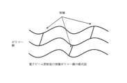
図1は、非晶性領域と結晶性領域とからなる半結晶性ポリマーを示しており、非晶性領域のポリマー鎖は、ポリマーの結晶性領域のラメラの積み重ねを一緒に結ぶゆるやかにらせん状に巻かれた鎖として現れる。フリーラジカルの移動性の欠如のために結晶性領域において鎖切断が優勢であるが、ポリマー鎖の絡み合いのために非晶性領域において架橋が支配的である。架橋ポリマー鎖は、図1および図2の両方に示されている。分子量の増加と架橋によって作られる3Dネットワークのために、架橋ポリマー材料は、高温において高粘度と高機械的強度を有する傾向にある。 Figure 1 shows a semi-crystalline polymer consisting of amorphous and crystalline regions, where the polymer chains in the amorphous regions appear as loosely spirally wound chains that link together stacks of lamellae in the crystalline regions of the polymer. While chain scission predominates in the crystalline regions due to the lack of free radical mobility, crosslinking predominates in the amorphous regions due to the entanglement of the polymer chains. Crosslinked polymer chains are shown in both Figures 1 and 2. Due to the increased molecular weight and the 3D network created by the crosslinks, crosslinked polymer materials tend to have high viscosity and high mechanical strength at high temperatures.
ポリマー材料は微多孔質電池セパレータ膜に使用され得る。電池セパレータは、陰極と陽極間の物理的接触を防止し、一方で、電池の充電および放電サイクル中の電界イオン流を可能にするために、電池システムにおける陰極、陽極間に配置された微多孔質膜を包含する。高エネルギー密度の二次リチウム電池(例えば、場合によっては、リチウムイオン電池)には、需要が高まっている。 The polymeric materials may be used in microporous battery separator membranes. Battery separators include microporous membranes disposed between the cathode and anode in a battery system to prevent physical contact between the cathode and anode while allowing field ion flow during the charge and discharge cycles of the battery. There is an increasing demand for high energy density secondary lithium batteries (e.g., in some cases, lithium ion batteries).
スマートフォンやラップトップコンピュータなどの民生用電子機器適用向け、電動工具向け、電気/ハイブリッド電気自動車応用の高エネルギーリチウム電池の需要が高まっている。かかる充電式、または二次的なリチウム電池には、リチウムイオン電池が包含される。リチウムイオン電池は、高性能微多孔質セパレータ膜を包含し得る。 There is an increasing demand for high energy lithium batteries for consumer electronics applications such as smart phones and laptop computers, for power tools, and for electric/hybrid electric vehicle applications. Such rechargeable, or secondary, lithium batteries include lithium ion batteries. Lithium ion batteries may include high performance microporous separator membranes.
少なくとも選択された実施態様によれば、本出願または発明は、上のニーズまたは需要に対処することができ、および/または新規または改良された膜、セパレータ膜、セパレータ、かかるセパレータを包含する電池、かかる膜および/またはセパレータの製造方法、および/またはかかる膜および/またはセパレータの使用方法を対象にする。少なくともある実施態様によれば、本発明は、二次電池または充電式リチウム電池用のイオン化放射処理されたポリオレフィン、ポリエチレン(PE)、コポリマーおよび/またはポリマーブレンド(例えば、PE、およびポリプロピレン(PP)などの他のポリマーを含むコポリマーまたはブレンド)二次または充電式リチウム電池用の電池セパレータ、および/またはイオン化放射処理された微多孔質膜電池セパレータの製造方法を対象にする。 According to at least selected embodiments, the present application or invention may address the above needs or demands and/or is directed to new or improved membranes, separator membranes, separators, batteries incorporating such separators, methods of making such membranes and/or separators, and/or methods of using such membranes and/or separators. According to at least certain embodiments, the present invention is directed to ionizing radiation treated polyolefin, polyethylene (PE), copolymers and/or polymer blends (e.g., copolymers or blends including PE and other polymers such as polypropylene (PP)) battery separators for secondary or rechargeable lithium batteries, and/or methods of making ionizing radiation treated microporous membrane battery separators.
少なくとも選択された実施態様、側面または目的によれば、本願または発明は、新規または改良されたセパレータ膜、セパレータ、かかるセパレータを包含する電池、かかる膜および/またはセパレータの製造方法、および/またはかかる膜および/またはセパレータの使用方法を提供し得るか、対象にする。少なくとも1つのある実施態様によれば、本発明は、イオン化放射処理された微多孔質ポリオレフィン、ポリエチレン(PE)、ポリプロピレン(PP)、コポリマーおよび/またはポリマーブレンド(例えば、PEおよびポリプロピレン(PP)などの他のポリマーを含むコポリマーまたはブレンド )膜、微
多孔質膜、セパレータ膜、電池セパレータ、および/または二次電池または充電式リチウム電池用の微多孔質電池セパレータ、および/またはイオン化放射処理膜、微多孔質膜、
セパレータ膜、電池セパレータ、および/または微多孔質電池セパレータの製造および/または使用方法を対象にする。
According to at least selected embodiments, aspects or objects, the present application or invention may provide or is directed to new or improved separator membranes, separators, batteries incorporating such separators, methods of making such membranes and/or separators, and/or methods of using such membranes and/or separators. According to at least one certain embodiment, the present invention provides ionizing radiation treated microporous polyolefin, polyethylene (PE), polypropylene (PP), copolymer and/or polymer blend (e.g., copolymers or blends including PE and other polymers such as polypropylene (PP)) membranes, microporous membranes, separator membranes, battery separators, and/or microporous battery separators for secondary batteries or rechargeable lithium batteries, and/or ionizing radiation treated membranes, microporous membranes,
The present invention is directed to methods of making and/or using separator membranes, battery separators, and/or microporous battery separators.
本発明の微多孔質膜または電池セパレータは、サーマルシャットダウンのより低い開始温度を提供することができ、物理的、寸法的および機械的完全性が高温で維持される拡大されたサーマルシャットダウン・ウインドウを有することができ、より良好な耐酸化性を有することができ、充電式リチウム電池の電池安全性能を改善することができ、処理されたポリエチレン、ポリプロピレンまたはポリオレフィンセパレータ膜を提供することができ、湿式プロセス製品に近いか、そのものまたはそれを上回る性能を有する処理された乾式プロセス製品を提供することができ、より高い温度性能を持つ処理されたポリエチレン、ポリプロピレンまたはポリオレフィンセパレータ膜を提供することができ、ポリプロピレンベースの製品の高温性能を持つ処理されたポリエチレンセパレータ膜を提供することができ、ポリプロピレンベースの多層または三層製品の高温性能を持つ処理されたポリエチレンセパレータ膜を提供することができ(例として、間にポリエチレンまたはポリプロピレン層を持つ2つのポリプロピレン層からなる三層膜、または間にポリプロピレンまたはポリエチレン層を持つ2つのポリエチレン層で作られている三層膜)、低減された熱収縮率を有することができ、電池システムにおける陰極と陽極の分離を維持し、高温、高エネルギー、高充電速度、および/または高電圧機能を改善し、安全性を改善し、および/または短絡、または充電式または二次リチウム電池、またはその組合せの熱暴走事象を回避するために重要な、熱的安定性と高温物理的完全性の両方をもたらす。 The microporous membrane or battery separator of the present invention can provide a lower onset temperature of thermal shutdown, can have an extended thermal shutdown window where physical, dimensional and mechanical integrity are maintained at high temperatures, can have better oxidation resistance, can improve the battery safety performance of rechargeable lithium batteries, can provide a treated polyethylene, polypropylene or polyolefin separator membrane, can provide a treated dry process product with performance approaching, matching or exceeding that of wet process products, can provide a treated polyethylene, polypropylene or polyolefin separator membrane with higher temperature performance, can provide a treated polypropylene based product with high temperature performance. Treated polyethylene separator membranes can be provided, treated polyethylene separator membranes can be provided that have high temperature performance for polypropylene-based multi-layer or tri-layer products (e.g., tri-layer membranes made of two polypropylene layers with a polyethylene or polypropylene layer between them, or tri-layer membranes made of two polyethylene layers with a polypropylene or polyethylene layer between them), can have reduced heat shrinkage, and provide both thermal stability and high temperature physical integrity that are important for maintaining separation of the cathode and anode in a battery system, improving high temperature, high energy, high charge rate, and/or high voltage capabilities, improving safety, and/or avoiding short circuits or thermal runaway events in rechargeable or secondary lithium batteries, or combinations thereof.
発明に係る微多孔質膜、または電池セパレータは、好ましくはサーマルシャットダウンの低開始温度を提供でき、高温で物理的、寸法的、および機械的完全性を維持する拡大されたサーマルシャットダウン・ウインドウを有することができ、充電式のリチウム電池における電池安全性能を改善することができ、ポリプロピレンベースの三層製品の高温性能を持つ処理されたポリエチレンセパレータ膜を提供することができ(例としてのみ、間にポリエチレンを持つ2つのポリプロピレン層で作られた三層膜)、低減された熱収縮率を有することができ、改善された熱安定性および高温物理的完全性の両方をもたらし、それは、電池システムの陰極と陽極の分離を維持し、充電式または二次リチウム電池、および/またはその組合せにおける熱暴走の事象を回避するために重要である。 The microporous membrane, or battery separator, of the invention can preferably provide a low onset temperature of thermal shutdown, have an extended thermal shutdown window that maintains physical, dimensional, and mechanical integrity at high temperatures, can improve battery safety performance in rechargeable lithium batteries, can provide a treated polyethylene separator membrane with the high temperature performance of polypropylene-based tri-layer products (by way of example only, a tri-layer membrane made of two polypropylene layers with polyethylene in between), can have reduced heat shrinkage, and can provide both improved thermal stability and high temperature physical integrity, which is important for maintaining separation of the cathode and anode of the battery system and avoiding thermal runaway events in rechargeable or secondary lithium batteries, and/or combinations thereof.
微多孔質ポリエチレン電池セパレータのイオン化放射処理は、サーマルシャットダウンの開始温度を低下させる発明に係る方法を提供する。さらに、イオン化放射で処理された微多孔質ポリエチレン電池セパレータ膜は、微多孔質セパレータ膜の物理的、寸法的および機械的完全性がより高い温度で維持される、拡大されたサーマルシャットダウン・ウインドウを有する。発明に係るイオン化放射処理されたセパレータ膜の拡大された高温寸法の完全性は、充電式リチウムイオン電池の電池安全性能を向上させる。加えて、発明に係るイオン化放射処理されたセパレータ膜の拡大された高温寸法の完全性は、ポリプロピレンベースの三層製品の高温性能に近づく(例としてのみ、間にポリエチレン層を有する2つのポリプロピレン層からなる三層膜)。加えて、本発明の電池セパレータ膜は、熱収縮率を低減し、電池システムにおける陰極および陽極の分離を維持し、充電式または二次リチウム電池の熱暴走事象を回避するために重要であり得る改良された熱安定性および高温物理的完全性の両方をもたらす。 Ionizing radiation treatment of microporous polyethylene battery separators provides an inventive method for lowering the onset temperature of thermal shutdown. Additionally, the microporous polyethylene battery separator membranes treated with ionizing radiation have an extended thermal shutdown window where the physical, dimensional and mechanical integrity of the microporous separator membrane is maintained at higher temperatures. The extended high temperature dimensional integrity of the inventive ionizing radiation treated separator membranes improves the battery safety performance of rechargeable lithium ion batteries. In addition, the extended high temperature dimensional integrity of the inventive ionizing radiation treated separator membranes approaches the high temperature performance of polypropylene based tri-layer products (by way of example only, a tri-layer membrane consisting of two polypropylene layers with a polyethylene layer in between). Additionally, the battery separator membranes of the present invention provide both improved thermal stability and high temperature physical integrity, which may be important for reducing thermal shrinkage, maintaining separation of the cathode and anode in a battery system, and avoiding thermal runaway events in rechargeable or secondary lithium batteries.
好ましいサーマルシャットダウンの特徴は、低開始温度、早いシャットダウン速度、および持続的サーマルシャットダウン・ウインドウである。サーマルシャットダウンの特徴を有することができる様々なセパレータは、単層ポリエチレン膜、またはポリプロピレンとポリエチレンからなる三層を包含し得るが、これに限定されるものではない。シャット
ダウンはその130~140℃の低融点のために、ポリエチレンによって提供され得る。本願明細書に開示するように、電子ビーム放射は、経済的で、容認でき、清潔で早い方法を使用して微多孔質電池セパレータ膜の熱的、機械的および/または化学的特性を改善し、特注に従って変更する手段を提供し得る。
Preferred thermal shutdown characteristics are low onset temperature, fast shutdown speed, and sustained thermal shutdown window. Various separators that can have thermal shutdown characteristics can include, but are not limited to, a monolayer polyethylene membrane, or a trilayer of polypropylene and polyethylene. Shutdown can be provided by polyethylene due to its low melting point of 130-140° C. As disclosed herein, electron beam radiation can provide a means to improve and customize the thermal, mechanical and/or chemical properties of microporous battery separator membranes using an economical, acceptable, clean and fast method.
スマートフォンやラップトップコンピュータ、電動工具などの民生用応用向け、電気/ハイブリッド電気自動車向けの高エネルギーまたは高電圧リチウム電池の需要が高まっている。いくつかのかかる充電式二次リチウム電池は、リチウムイオン電池を包含する。リチウムイオン電池には、高性能の微多孔質セパレータ膜を包含する。本願明細書に記載されるとおり、電子ビーム放射は、経済的で、電子ビーム促進の方向において優れた指向性を有し、ならびに高処理速度で実行し得るプロセスを使用して、微多孔質電池セパレータ膜の機械的、熱的および化学的特性を改善し、特注に従って変更するための手段を提供し得る。 There is an increasing demand for high energy or high voltage lithium batteries for consumer applications such as smart phones, laptop computers, power tools, and for electric/hybrid electric vehicles. Some such rechargeable secondary lithium batteries include lithium ion batteries. Lithium ion batteries include high performance microporous separator membranes. As described herein, electron beam radiation can provide a means to improve and customize the mechanical, thermal, and chemical properties of microporous battery separator membranes using a process that is economical, has excellent directionality in the direction of electron beam acceleration, and can be performed at high throughput rates.
電子ビーム(e-ビーム)放射線を使用したイオン化放射処理は、充電式、または二次リチウム電池(例としてのみ、リチウム金属電池、リチウムイオン電池など)などの様々な電池の安全性および/または性能を最適化するために、微多孔質電池セパレータ膜の機械的、熱的および/または化学的特性の改変を制御し、および特注に従って変更する方法である。微多孔質セパレータ膜の熱収縮率の減少は、リチウム電池における高温での寸法安定性のレベルの向上および安全性能の改善をもたらす。セパレータ膜の熱収縮率が非常に低いかまたは零であると、陰極と陽極との間の物理的接触が防止され、電池の電子的短絡の可能性が低減される。 Ionizing radiation treatment using electron beam (e-beam) radiation is a method for controlled and customized modification of the mechanical, thermal and/or chemical properties of microporous battery separator membranes to optimize safety and/or performance of various batteries, such as rechargeable or secondary lithium batteries (by way of example only, lithium metal batteries, lithium ion batteries, etc.). The reduction in the thermal shrinkage of the microporous separator membranes results in increased levels of dimensional stability and improved safety performance at elevated temperatures in lithium batteries. The very low or no thermal shrinkage of the separator membranes prevents physical contact between the cathode and anode, reducing the possibility of electronic shorting of the battery.
繰り返しの充電と放電のサイクルは、電池内の一部の内部部品の寸法が変化し得る。電池アセンブリプロセスは、層の陰極/セパレータ/陽極の積み重ねを包含し得るか、ロールケーキタイプの構成で巻かれた積み重ね陰極/セパレータ/陽極の全長を包含し得る。陰極と陽極の間の物理的および電気的絶縁は、セパレータによって提供される。機械方向または横方向のセパレータの収縮率は、場合によっては、陰極と陽極間の接触を導き、短絡または熱暴走事象に対するポテンシャルを生じる。 Repeated charge and discharge cycles can change the dimensions of some internal components within the battery. The battery assembly process can involve stacking of cathode/separator/anode in layers or can involve a full length of stacked cathode/separator/anode rolled in a roll cake type configuration. Physical and electrical insulation between the cathode and anode is provided by the separator. Shrinkage of the separator in the machine or cross direction can potentially lead to contact between the cathode and anode, creating the potential for a short circuit or thermal runaway event.
ポリエチレン(PE)微多孔質電池セパレータ膜の電子ビーム処理は、膜の熱寸法収縮率の低減を達成し得る。湿式法または乾式法を用いて製造されたPE微多孔質電池セパレータ膜に対して電子ビーム処理を行い得る。湿式プロセスは、熱誘導相分離プロセス(またはTIPSプロセス)を包含し、それは典型的にはポリマーおよび加工助剤(および可能であれば他の成分)を溶融および混合して非多孔質押出物前駆体膜を形成し、続いて任意の順序で、または複数のステップの組み合わせで1以上の抽出ステップが続くか、または先行し得る、一軸方向および二軸方向の1以上の伸張ステップを包含する。電子ビーム処理は、延伸前または延伸後、抽出前または押出後に、任意の順序で、最終的に完成した良品およびこれらのステップの任意の組み合わせで、非多孔質押出物前駆体膜上で行うことができる。 Electron beam treatment of polyethylene (PE) microporous battery separator membranes can achieve a reduction in the thermal dimensional shrinkage of the membrane. Electron beam treatment can be performed on PE microporous battery separator membranes manufactured using wet or dry processes. Wet processes include the thermally induced phase separation process (or TIPS process), which typically involves melting and mixing the polymer and processing aids (and possibly other ingredients) to form a nonporous extrudate precursor membrane, followed by one or more uniaxial and biaxial stretching steps that may be followed or preceded by one or more extraction steps in any order or combination of steps. Electron beam treatment can be performed on the nonporous extrudate precursor membrane before or after stretching, before extraction or after extrusion, in any order, and on the final finished good product and any combination of these steps.
電池の安全性を向上させるために、リチウム電池製造業者は、セパレータの孔が閉じてシャットダウン温度での電極間のイオンの流れを阻止するサーマルシャットダウン機能を持つ微多孔質電池セパレータを使用し得る。イオンの流れがなければ、電池は機能しなくなる。シャットダウンされた微多孔質電池セパレータ膜の電子ビーム放射処理は、サーマルシャットダウンの開始温度を調整する手段を提供し得る。シャットダウンが可能な微多孔質電池セパレータ膜の電子線照射処理は、サーマルシャットダウンの開始温度を微調整し、開始温度をより低い温度に調整する手段を提供し得る。より低いサーマルシャットダウン温度を持つ微多孔質電池セパレータ膜は、低温でイオン流の妨害状態を提供する。 To improve battery safety, lithium battery manufacturers may use microporous battery separators with thermal shutdown capabilities where the pores of the separator close to prevent ion flow between the electrodes at a shutdown temperature. Without ion flow, the battery will not function. Electron beam irradiation treatment of a shut down microporous battery separator membrane may provide a means to tune the onset temperature of thermal shutdown. Electron beam irradiation treatment of a shut down capable microporous battery separator membrane may provide a means to fine tune the onset temperature of thermal shutdown, adjusting the onset temperature to a lower temperature. A microporous battery separator membrane with a lower thermal shutdown temperature provides an impeded condition for ion flow at lower temperatures.
サーマルシャットダウンは、セパレータ膜の電気抵抗を温度の関数として測定する電気抵抗テストを使用して測定することができる。電気抵抗(ER)は、電解質で満たされたセパレータのオーム・cm2での抵抗値で定義される。電池セパレータ膜でサーマルシャットダウンが発生すると、ERは約1,000~10,000オーム・cm2オーダーの高レベルの抵抗値に達する。セパレータ膜が180℃以上の高温でこのレベルの電気抵抗を維持する場合、これは持続された高温サーマルシャットダウンと呼ばれる。サーマルシャットダウン温度の低下とシャットダウン温度持続の延長は、サーマルシャットダウンの持続された‘窓’を広げる。広いサーマルシャットダウン・ウインドウは、熱暴走事象のポテンシャル、および火災または爆発の可能性を低減することによって電池の安全性を改良し得る。 Thermal shutdown can be measured using an electrical resistance test, which measures the electrical resistance of the separator membrane as a function of temperature. Electrical resistance (ER) is defined as the resistance in ohms- cm2 of a separator filled with electrolyte. When thermal shutdown occurs in a battery separator membrane, the ER reaches a high level of resistance, on the order of about 1,000-10,000 ohms- cm2 . If the separator membrane maintains this level of electrical resistance at temperatures as high as 180°C or higher, it is called a sustained high temperature thermal shutdown. Reducing the thermal shutdown temperature and extending the shutdown temperature duration widens the sustained 'window' of thermal shutdown. A wide thermal shutdown window can improve battery safety by reducing the potential for thermal runaway events and the possibility of fire or explosion.
サーマルシャットダウンはポリマーの融点またはその近傍で起こる。ポリエチレン微多孔質電池セパレータ膜のサーマルシャットダウンは、PEの分子量に依存し、130℃~145℃の範囲のPEの融点で起こる。電池の温度が150℃に上昇すると、特定のPEセパレータ膜の融点の完全性の損失のために、サーマルシャットダウンは失われ得る。ポリエチレン微多孔質電池セパレータのサーマルシャットダウン・ウインドウは、場合によっては、5-15℃で、それは狭いウインドウと見なされ得る。ポリプロピレン(PP)とポリエチレン(PE)を含有する三層の微多孔質電池セパレータ膜において、ポリプロピレン部分は約165℃で溶融し得る。 Thermal shutdown occurs at or near the melting point of the polymer. Thermal shutdown of polyethylene microporous battery separator membranes occurs at the melting point of PE, which ranges from 130°C to 145°C, depending on the molecular weight of the PE. If the temperature of the battery increases to 150°C, thermal shutdown may be lost due to loss of integrity of the melting point of the particular PE separator membrane. The thermal shutdown window of polyethylene microporous battery separators is, in some cases, 5-15°C, which may be considered a narrow window. In a tri-layer microporous battery separator membrane containing polypropylene (PP) and polyethylene (PE), the polypropylene portion may melt at approximately 165°C.
ポリプロピレン/ポリエチレン/ポリプロピレン(PP/PE/PP)三層電池セパレータ膜のサーマルシャットダウンは、場合によっては、PE層のために135~145℃のサーマルシャットダウン開始温度を有する可能性があるが、PP層のために165℃まで十分に溶融しない。持続的なサーマルシャットダウン・ウインドウは、場合によっては135~145℃から165℃まで発生し得、PP層の完全性が失われるまで続く。したがって、場合によっては、PP/PE/PP三層電池セパレータ膜のサーマルシャットダウン・ウインドウは、例えば単層ポリエチレンセパレータのサーマルシャットダウン・ウインドウよりも広く、したがって、リチウム充電式電池の良好な熱性能などのいくつかの所望の特徴を有し得る。 Thermal shutdown of a polypropylene/polyethylene/polypropylene (PP/PE/PP) tri-layer battery separator membrane may in some cases have a thermal shutdown onset temperature of 135-145°C due to the PE layer, but does not melt sufficiently until 165°C due to the PP layer. A sustained thermal shutdown window may in some cases occur from 135-145°C up to 165°C, continuing until the integrity of the PP layer is lost. Thus, in some cases, the thermal shutdown window of a PP/PE/PP tri-layer battery separator membrane may be wider than that of, for example, a mono-layer polyethylene separator, and therefore may have some desirable characteristics, such as good thermal performance in lithium rechargeable batteries.
熱的性能に関しては、様々なPE微多孔質電池セパレータのためのサーマルシャットダウン・ウインドウを広げることが望ましい場合がある。PE微多孔質電池セパレータ膜の電子ビーム処理は、より低いシャットダウン開始温度およびより高い溶融完全性のPE層を達成し、所望の広げられたサーマルシャットダウン・ウインドウを生成する。 With regard to thermal performance, it may be desirable to widen the thermal shutdown window for various PE microporous battery separators. Electron beam treatment of PE microporous battery separator membranes achieves lower shutdown initiation temperatures and higher melt integrity of the PE layer, producing the desired widened thermal shutdown window.
電子ビーム処理は、微多孔質電池セパレータ膜の電解質湿潤を改善する追加の利益を有し得る。PE微多孔質電池レータ膜の低e-ビーム放射は、セパレータ膜表面上と微多孔質セパレータ膜の内部多孔質構造内の両方の電解質液の接触角を減少させることによって、リチウム電池の電解質湿潤を変化させ得る。より低い接触角は、リチウム電池の容量を改良するように導き得る高い電解質吸収を示す。 Electron beam treatment may have the additional benefit of improving electrolyte wetting of microporous battery separator membranes. Low e-beam irradiation of PE microporous battery separator membranes may alter the electrolyte wetting of lithium batteries by reducing the contact angle of the electrolyte liquid both on the separator membrane surface and within the internal porous structure of the microporous separator membrane. Lower contact angles indicate higher electrolyte absorption which may lead to improved capacity of lithium batteries.
少なくとも選択された実施態様によれば、本願または本発明は、新規または改善されたセパレータ膜、セパレータ、かかるセパレータを包含する電池、かかる膜および/またはセパレータの製造方法、および/またはかかる膜および/またはセパレータの使用方法を対象にする。少なくとも1つの特定の実施態様によれば、本発明は、イオン化放射で処理された微孔性ポリオレフィン、ポリエチレン(PE)、コポリマーおよび/またはポリマーブレンド(例えば、PEとポリプロピレン(PP)などの他のポリマーを含むコポリマーまたはブレンド)二次または充電式リチウム電池用電池セパレータ、および/またはイオン化放射処理された微多孔質電池セパレータの製造方法を対象にする。PEを含むブレンドまたはコポリマーが使用される様々な実施態様において、かかるブレンドまたはコポリマーは、例えば、約90%以上のPE、または約95%以上のPEなどを包含し得る。 According to at least selected embodiments, the present application or invention is directed to new or improved separator membranes, separators, batteries incorporating such separators, methods of making such membranes and/or separators, and/or methods of using such membranes and/or separators. According to at least one particular embodiment, the present invention is directed to ionizing radiation treated microporous polyolefin, polyethylene (PE), copolymers and/or polymer blends (e.g., copolymers or blends including PE and other polymers such as polypropylene (PP)) battery separators for secondary or rechargeable lithium batteries, and/or methods of making ionizing radiation treated microporous battery separators. In various embodiments in which PE-containing blends or copolymers are used, such blends or copolymers may include, for example, about 90% or more PE, or about 95% or more PE, etc.
本発明に係る微多孔質膜または電池セパレータは、好ましくは、サーマルシャットダウンのより低い開始温度を提供し、物理的、寸法的、および機械的完全性が高温で維持される、拡大されたサーマルシャットダウン・ウインドウを有することができ、充電式リチウム電池において、電池安全性能を改善することができ、ポリプロピレンベースの三層製品の高温性能を持つ処理されたポリエチレンセパレータ膜を提供することができ、(一例としてのみ、ポリエチレン層を間に有する2つのポリプロピレン層からなる三層膜)、熱収縮率を低減して、電池システムにおいて陰極と陽極の分離を維持し、充電式、または二次
リチウム電池、および/またはそれらの組み合わせにおける熱暴走事象を回避するために重要である、熱安定性と高温物理的完全性の両方をもたらし得る。
The microporous membrane or battery separator of the present invention may preferably provide a lower onset temperature of thermal shutdown, have an extended thermal shutdown window where physical, dimensional, and mechanical integrity are maintained at high temperatures, improve battery safety performance in rechargeable lithium batteries, provide a treated polyethylene separator membrane with the high temperature performance of polypropylene based tri-layer products (by way of example only, a tri-layer membrane consisting of two polypropylene layers with a polyethylene layer between), reduce thermal shrinkage, maintain separation of cathode and anode in battery systems, and provide both thermal stability and high temperature physical integrity that are important for avoiding thermal runaway events in rechargeable or secondary lithium batteries, and/or combinations thereof.
微多孔質ポリエチレン電池セパレータのイオン化放射処理は、サーマルシャットダウンの開始温度を低下させる方法を提供する。さらに、イオン化放射で処理された微多孔質ポリエチレン電池セパレータ膜は、微多孔質セパレータ膜の物理的、寸法的および機械的完全性がより高い温度で維持される、拡大されたサーマルシャットダウン・ウインドウを有する。本発明に係るイオン化放射処理されたセパレータ膜の拡大された高温寸法の完全性は、充電式リチウムイオン電池の電池安全性能を向上させる。さらに、本発明のイオン化放射処理されたセパレータ膜の拡大された高温寸法の完全性は、ポリプロピレンベースの三層製品の高温性能に近づく(一例としてのみ、間にポリエチレン層を有する2つのポリプロピレン層から作られた三層膜)。加えて、本発明に係る電池セパレータ膜は、熱収縮率を低減し、電池システムにおける陰極と陽極の分離を維持し、充電式または二次リチウム電池の熱暴走事象を回避するために重要である熱安定性および高温物理的完全性の両方をもたらし得る。 Ionizing radiation treatment of microporous polyethylene battery separators provides a method to reduce the onset temperature of thermal shutdown. Additionally, microporous polyethylene battery separator membranes treated with ionizing radiation have an extended thermal shutdown window where the physical, dimensional and mechanical integrity of the microporous separator membrane is maintained at higher temperatures. The extended high temperature dimensional integrity of the ionizing radiation treated separator membranes of the present invention improves the battery safety performance of rechargeable lithium ion batteries. Additionally, the extended high temperature dimensional integrity of the ionizing radiation treated separator membranes of the present invention approaches the high temperature performance of polypropylene based tri-layer products (as an example only, a tri-layer membrane made from two polypropylene layers with a polyethylene layer in between). Additionally, the battery separator membranes of the present invention can provide both thermal stability and high temperature physical integrity, which are important for reducing thermal shrinkage, maintaining separation of the cathode and anode in battery systems, and avoiding thermal runaway events in rechargeable or secondary lithium batteries.
電子線放射の形態のイオン化放射処理は、微多孔質電池セパレータ膜の熱的、機械的および/または化学的特性または側面を制御および改変し、様々な二次または充電式リチウム電池におけるその安全性および/または性能を最適化する方法または手段を提供し得る。本明細書に記載の様々な実施態様において、e-ビーム放射は、セパレータ膜上で単独で実施されてもよく、または熱処理、IR処理、他の化学的架橋処理などの他の処理の前、後、または同時に行い得る。 Ionizing radiation treatment in the form of electron beam radiation may provide a method or means to control and modify the thermal, mechanical and/or chemical properties or aspects of a microporous battery separator membrane to optimize its safety and/or performance in various secondary or rechargeable lithium batteries. In various embodiments described herein, e-beam radiation may be performed alone on the separator membrane or may be performed before, after, or simultaneously with other treatments such as thermal treatments, IR treatments, other chemical crosslinking treatments, etc.
充電式リチウム電池製造業者は、厚さ6~20μm(場合により薄いものさえ)、より好ましくは厚さ8~16μmの範囲、最も好ましくは厚さ8~14μmの範囲の薄い微多孔質セパレータ膜をしばしば要求する。リチウム電池製造業者は、リチウム電池の安全性能に非常に重点を置いており、電池セパレータ膜がエネルギー密度、サイクル寿命および電池の安全性において重要な役割を果たすと考えている。 Rechargeable lithium battery manufacturers often require thin microporous separator membranes with thicknesses of 6-20 μm (sometimes even thinner), more preferably in the range of 8-16 μm thick, and most preferably in the range of 8-14 μm thick. Lithium battery manufacturers place great emphasis on the safety performance of lithium batteries and believe that the battery separator membrane plays a key role in the energy density, cycle life and safety of the battery.
薄いセパレータは、高いエネルギー密度のリチウム電池、例えば重量の軽いリチウムイオン電池を製造しようと努める電池製造業者に好まれる。セパレータ膜が薄ければそれだけ、より多くの電極/セパレータのサンドイッチが電池セルに詰め込まれ、高エネルギー密度をもたらす。しかし乍ら、14μm未満の厚さを持つ薄い電池セパレータは、高温で機械方向(MD)と横方向(TD)の両方で寸法的に安定であるべきであり、また電池の充電および放電サイクル最中に電池の陽極と陰極間の物理的分離を維持するために、低い熱MDおよびTD収縮率を有するべきである。 Thin separators are preferred by battery manufacturers seeking to produce high energy density lithium batteries, e.g., lithium-ion batteries, with low weight. The thinner the separator membrane, the more electrode/separator sandwiches can be packed into a battery cell, resulting in high energy density. However, thin battery separators with thicknesses less than 14 μm should be dimensionally stable in both the machine direction (MD) and transverse direction (TD) at high temperatures and should have low thermal MD and TD shrinkage to maintain physical separation between the battery anode and cathode during charge and discharge cycling of the battery.
充電および放電サイクルを繰り返すと、電池寿命を通じて電池セパレータ膜の寸法において変化を引き起こす。電池アセンブリ工程は、陰極/セパレータ/陽極の積み重ね、またはロールケーキタイプの構成において巻かれた積み重ね陰極/セパレータ/陽極サンドイッチ状の構造の全長を含む。セパレータは、陰極、陽極間の物理的、電気的絶縁を提供する。セパレータの機械方向または横方向の収縮率は、陰極と陽極間の接触を導き、短絡または熱暴走事象のポテンシャル、および電池火災や爆発のポテンシャルを生じる。 Repeated charge and discharge cycles cause changes in the dimensions of the battery separator membrane throughout the life of the battery. The battery assembly process involves the length of the cathode/separator/anode stack or stacked cathode/separator/anode sandwich-like structure rolled in a roll-cake type configuration. The separator provides physical and electrical insulation between the cathode and anode. Shrinkage in the machine or cross direction of the separator can lead to contact between the cathode and anode, creating the potential for a short circuit or thermal runaway event, and the potential for battery fire or explosion.
単層および多層ポリエチレン微多孔質セパレータ膜は、リチウム電池における安全性能を改善するために、電子ビーム放射でそれらの熱機械的性能特性を変更するように処理することができる(一例として、単層および多層膜、コポリマー膜、ポリマーブレンド 膜
、および/またはそれらの組合せを包含する)。電子ビーム照射の線量の範囲は、ポリマーの分子量、ポリマーの結晶化度/非晶質含有量、装置のプロセス条件、処理前および処理中のガス雰囲気曝露の化学的性質、 処理される膜の厚さ、ならびに目標とするセパレ
ータ膜の化学的、機械的および熱的性能特性などいくつかの要因に依存する。本明細書に記載される様々な実施態様において、使用されるポリマーは、約800,000未満の分子量を有するポリエチレンであり得る。 いくつかの実施態様において、ポリエチレンは
高密度ポリエチレンである。
Monolayer and multilayer polyethylene microporous separator membranes can be treated with electron beam radiation to modify their thermomechanical performance properties to improve safety performance in lithium batteries (including, by way of example, monolayer and multilayer membranes, copolymer membranes, polymer blend membranes, and/or combinations thereof). The dose range of electron beam radiation depends on several factors, such as the molecular weight of the polymer, the crystallinity/amorphous content of the polymer, the process conditions of the equipment, the chemistry of the gas atmosphere exposure before and during treatment, the thickness of the membrane being treated, and the chemical, mechanical, and thermal performance properties of the separator membrane that are targeted. In various embodiments described herein, the polymer used can be a polyethylene having a molecular weight of less than about 800,000. In some embodiments, the polyethylene is a high density polyethylene.
半結晶性ポリマーは、非晶性領域と、非晶性領域内のポリマー鎖がポリマーの結晶領域のラメラスタックと結び付ける結晶領域とからなる。結晶性領域の量は、結晶化度または結晶化度パーセントによって示される。ポリオレフィンの結晶化度は、電子ビームが鎖切断によって化学結合を破壊し、より短いポリマー鎖を生成し得るため、電子ビーム放射への曝露によって影響され得る。電子ビーム処理はまた、図2に示すように、ポリマー鎖間の架橋反応を生じさせることができるフリーラジカル化学種を生成することができ、より長いポリマー鎖を作るか、または化学結合したポリマー鎖のネットワークを作り出す。 Semicrystalline polymers consist of amorphous regions and crystalline regions where polymer chains in the amorphous regions connect with lamellar stacks in the crystalline regions of the polymer. The amount of crystalline regions is indicated by the degree of crystallinity or percent crystallinity. The crystallinity of polyolefins can be affected by exposure to electron beam radiation because the electron beam can break chemical bonds through chain scission, producing shorter polymer chains. Electron beam treatment can also produce free radical species that can cause crosslinking reactions between polymer chains, making longer polymer chains or creating a network of chemically bonded polymer chains, as shown in Figure 2.
連鎖切断対架橋活性の優位性は、ポリマーのタイプ、その分子量および分布、結晶化度、アモルファス含有量、および立体規則性などのパラメータを選択することによって、および圧力、温度、選択された気体雰囲気中の酸素の存在および電子ビーム線量などの電子ビーム処理条件を選択することによってバランスされる。多くのポリマーは架橋および切断の両方を受け、これらのプロセスのうちの優位性は、ポリマーの化学構造および形態、ならびに選択された電子ビーム処理条件に依存する。 The dominance of chain scission versus crosslinking activity is balanced by selecting parameters such as the type of polymer, its molecular weight and distribution, crystallinity, amorphous content, and stereoregularity, and by selecting electron beam processing conditions such as pressure, temperature, the presence of oxygen in the selected gas atmosphere, and electron beam dose. Many polymers undergo both crosslinking and scission, and the dominance of these processes depends on the chemical structure and morphology of the polymer, as well as the selected electron beam processing conditions.
電池メーカーは、リチウムイオン電池などの高エネルギー電池の高まる需要から、セパレータ膜が薄ければ薄いほど、より多くの電極材料を電池セルに設計することができるので、厚さ8~20μm、より好ましくは厚さ8~16μm、最も好ましくは厚さが8~14μmの範囲にある非常に薄い微多孔質セパレータ膜を使用している。より薄いセパレータ膜は、単位体積当たりのポリマーがより少なく、したがって、場合によっては、より厚いセパレータよりも機械方向および横方向の二次元X-Y方向の機械的強度が弱いことがある。より薄いセパレータ膜は単位体積当たりのポリマーが少ないため、場合によっては、より厚いセパレータよりも穿刺強度によって測定される“Z”方向でより弱くなり得る。E-ビーム処理は、ポリマー鎖の長さ、鎖間のポリマー間結合の量、およびポリマー鎖の絡まりを化学的および永久的に改変することによって、X、YおよびZ方向のセパレータ膜の高温機械的強度を改良するために使用し得る。 Battery manufacturers use very thin microporous separator membranes ranging from 8-20 μm thick, more preferably 8-16 μm thick, and most preferably 8-14 μm thick, because the thinner the separator membrane, the more electrode material can be designed into the battery cell due to the increasing demand for high energy batteries such as lithium ion batteries. Thinner separator membranes have less polymer per unit volume and therefore, in some cases, may have weaker mechanical strength in the two dimensional X-Y directions, the machine direction and the transverse direction, than thicker separators. Because thinner separator membranes have less polymer per unit volume, in some cases, they may be weaker in the "Z" direction, as measured by puncture strength, than thicker separators. E-beam processing can be used to improve the high temperature mechanical strength of separator membranes in the X, Y, and Z directions by chemically and permanently modifying the length of the polymer chains, the amount of interpolymer bonds between the chains, and the entanglement of the polymer chains.
ポリマー材料の電子ビーム放射は、フリーラジカルの生成に導き得る。フリーラジカルは、ポリマー材料において分解および/または架橋現象に導き得る。連鎖劣化に伴うフリーラジカル生成の優位性対e-ビーム処理の結果としての連鎖延長につながる架橋の発生は、ポリマー中の結晶性および非晶性領域の量によって影響を受ける。e-ビーム処理は、架橋として知られているポリマー間結合の形成によって、ポリマーの非晶性領域に影響を及ぼす。図1は、ポリマー上のe-ビーム放射の結果を示す。e-ビーム処理は、ポリマー鎖のより利用可能な部分、例えば、折り畳まれたラメラ結晶領域のポリマー鎖の1つ以上の外側の曲げ部上にフリーラジカルを生成する鎖の切断によって、ポリマーの結晶領域に影響を及ぼし得る。 Electron beam irradiation of polymeric materials can lead to the generation of free radicals. Free radicals can lead to degradation and/or crosslinking phenomena in polymeric materials. The predominance of free radical generation with chain degradation versus the occurrence of crosslinking leading to chain extension as a result of e-beam treatment is influenced by the amount of crystalline and amorphous regions in the polymer. E-beam treatment affects the amorphous regions of a polymer by the formation of interpolymer bonds known as crosslinks. Figure 1 shows the results of e-beam irradiation on a polymer. E-beam treatment can affect the crystalline regions of a polymer by chain scission generating free radicals on the more available parts of the polymer chains, for example on one or more outer bends of the polymer chains in folded lamellar crystalline regions.
ポリエチレンセパレータ膜のe-ビーム(またはeビーム)処理は、電子ビーム線量の選択に応じて機械的強度特性のいくつかに影響を及ぼし得る。本発明のセパレータ膜のMDおよびTD引張強さ、引張歪みおよびヤング率のような機械的特性は、多くの実験的努力で決定されたプロセス条件のために、9μmおよび12μmの微多孔質セパレータ膜のe-ビーム処理によって悪影響を受けない。さらに、e-ビーム処理されたPE微多孔質セパレータ膜の絶縁破壊、微小押し込みおよび混合浸透は、悪影響を受けない。熱機械分析(TMA)は、試験サンプルが一定の張力下に保持され、温度が室温から上昇した温度に上昇するテンションモードで実施すると、熱破断温度がより高い温度にシフトする(図
11参照)。
E-beam (or e-beam) treatment of polyethylene separator membranes can affect some of the mechanical strength properties depending on the choice of electron beam dose. Mechanical properties such as MD and TD tensile strength, tensile strain and Young's modulus of the separator membranes of the present invention are not adversely affected by e-beam treatment of 9 μm and 12 μm microporous separator membranes due to process conditions determined in many experimental efforts. Furthermore, the dielectric breakdown, microindentation and mixed infiltration of e-beam treated PE microporous separator membranes are not adversely affected. Thermomechanical analysis (TMA) performed in tension mode where test samples are held under constant tension and the temperature is increased from room temperature to elevated temperatures shifts the thermal rupture temperature to higher temperatures (see FIG. 11).
熱破裂温度は、温度が上昇するにつれて膜が加えられた張力下で壊れる温度である。微多孔質PEセパレータ膜のe-ビーム処理の結果としての架橋の効果は、破裂温度のこの上方シフトを引き起こし、e-ビーム処理膜がより高温での張力下で容易に破損しないことを実証する。100kGyの電子ビーム線量後の寸法変化率は急激ではない。e-ビーム処理は、PE微多孔質セパレータ膜の熱破裂温度を、リチウムイオン電池などの電池の所望の熱的性能に応じて高くまたは低く移動させることによって微調整する方法を提供する。 The thermal burst temperature is the temperature at which the membrane breaks under applied tension as the temperature is increased. The effect of crosslinking as a result of e-beam treatment of the microporous PE separator membrane causes this upward shift in burst temperature, demonstrating that the e-beam treated membrane does not break as easily under tension at higher temperatures. The rate of dimensional change after an electron beam dose of 100 kGy is not as rapid. E-beam treatment provides a way to fine-tune the thermal burst temperature of the PE microporous separator membrane by moving it higher or lower depending on the desired thermal performance of the battery, such as a lithium ion battery.
サーマルシャットダウンは、微多孔質セパレータ膜の孔が閉じ、セパレータ膜がもはやイオンを伝導することができない温度で起こる。ポリエチレン微多孔質電池セパレータ膜のサーマルシャットダウンは、PEの分子量、密度、立体規則性および結晶化度に依存し、典型的には130~145℃の範囲内にあるポリマーの融点またはその付近で生じる。電池セパレータ膜でサーマルシャットダウンが発生すると、電気抵抗(ER)は約1,000~10,000オーム・cm2程度の高レベルの抵抗に達し、電池は“シャットダウン”状態にあると言われる。セパレータ膜が≧180℃の温度でこのレベルの電気抵抗を維持する場合、これは持続的な高温サーマルシャットダウンと呼ばれる。 Thermal shutdown occurs at a temperature where the pores in the microporous separator membrane close and the separator membrane can no longer conduct ions. Thermal shutdown in polyethylene microporous battery separator membranes occurs at or near the melting point of the polymer, which depends on the molecular weight, density, stereoregularity and crystallinity of the PE and is typically in the range of 130-145°C. When thermal shutdown occurs in a battery separator membrane, the electrical resistance (ER) reaches a high level of resistance, on the order of about 1,000-10,000 ohms cm2 , and the battery is said to be in a "shutdown" state. If the separator membrane maintains this level of electrical resistance at temperatures ≧180°C, it is referred to as a sustained high temperature thermal shutdown.
ポリエチレン微多孔質セパレータ膜の場合、電池温度が130~145℃に達し、サーマルシャットダウンが発生した後も、電池の温度は上昇し続ける可能性がある。150℃の温度では、場合によっては、ポリエチレンセパレータ膜の‘溶融完全性’の損失のためにサーマルシャットダウンが失われ得る。溶融完全性は、膜が軟化しているがその形状を保持している寸法によって定義される膜の物理的構造をいう。溶融完全性の損失は、膜がもはやその形状を保持せず、流体であることを意味する。電池の安全性の観点からは、微多孔質セパレータ膜が高温で物理的形状を維持し、高温溶融完全性(HTMI)を有することが望ましい。 For polyethylene microporous separator membranes, the temperature of the battery may continue to rise even after the battery temperature reaches 130-145°C and thermal shutdown occurs. At temperatures of 150°C, in some cases thermal shutdown may be lost due to loss of 'melt integrity' of the polyethylene separator membrane. Melt integrity refers to the physical structure of the membrane, defined by the dimensions where the membrane has softened but retained its shape. Loss of melt integrity means that the membrane no longer retains its shape and is fluid. From a battery safety perspective, it is desirable for the microporous separator membrane to maintain its physical shape at high temperatures and have high temperature melt integrity (HTMI).
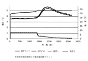
図3の実施例3の電子ビーム処理されたポリエチレン微多孔質セパレータ膜は、約137.5℃で熱シャットダウンが開始されてから180℃まで延長されたサーマルシャットダウン・ウインドウを有する。サーマルシャットダウンの開始に伴い、電気抵抗(ER)が10オーム・cm2から10,000オーム・cm2以上に急激に上昇し、セパレータ膜の孔がポリマーの溶融により閉じられ、電池の中のイオンの流れが遮断されることが示される。膜の物理的完全性が維持され、ERが高いままであると、電池セパレータは、陽極を陰極から分離する物理的障壁をもたらし、熱暴走事象が起こる機会を妨げている。 The electron beam treated polyethylene microporous separator membrane of Example 3 in Figure 3 has an extended thermal shutdown window from about 137.5°C with thermal shutdown initiation at 180°C. With the onset of thermal shutdown, the electrical resistance (ER) rises sharply from 10 ohms cm2 to over 10,000 ohms cm2 , indicating that the pores in the separator membrane are closing due to melting of the polymer, blocking the flow of ions through the battery. If the physical integrity of the membrane is maintained and the ER remains high, the battery separator provides a physical barrier separating the anode from the cathode, preventing the opportunity for a thermal runaway event to occur.
約25μm以下の厚さを有する典型的なポリエチレン微多孔質電池セパレータのサーマルシャットダウン・ウインドウは、5~15℃程度、時にはさらに低い(例えば、3℃の約144~147℃の全シャットダウン・ウインドウ)。これは狭いサーマルシャットダウン・ウインドウであると考えられる。サーマルシャットダウン・ウインドウを増加させる1つの可能な手段は、より高い溶融温度のポリマーをPEに組み入れることである。多孔質セパレータ膜のサーマルシャットダウン・ウインドウを延長する別の方法は、ポリプロピレン多孔質膜層などの1つ以上のより高い溶融温度の多孔質層で該PEを層状にすることである。サーマルシャットダウン・ウインドウは、例えば、‘ポリプロピレン/ポリエチレン/ポリプロピレン’三層分離膜構成においてポリプロピレン(PP)を使用することによって調整することもでき、この場合、内側のポリエチレン層は130~145℃の早期サーマルシャットダウンに寄与し、ポリプロピレン外層は165℃付近でより高いサーマルシャットダウンに寄与する。 The thermal shutdown window of a typical polyethylene microporous battery separator with a thickness of about 25 μm or less is on the order of 5-15°C, sometimes even lower (e.g., a total shutdown window of about 144-147°C of 3°C). This is considered a narrow thermal shutdown window. One possible means of increasing the thermal shutdown window is to incorporate a higher melting temperature polymer into the PE. Another way to extend the thermal shutdown window of a porous separator membrane is to layer the PE with one or more higher melting temperature porous layers, such as a polypropylene porous membrane layer. The thermal shutdown window can also be tailored by using polypropylene (PP), for example, in a 'polypropylene/polyethylene/polypropylene' three-layer separator configuration, where the inner polyethylene layer contributes to an early thermal shutdown of 130-145°C, and the polypropylene outer layer contributes to a higher thermal shutdown around 165°C.
ポリプロピレン/ポリエチレン/ポリプロピレン(PP/PE/PP)の三層電池セパ
レータ膜のサーマルシャットダウンは、130℃程度の低い開始温度を有し得る。と言うのは、PE内部層は、 いくつかの湿式プロセスPE膜またはフィルムを製造するために
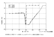
使用されるPEよりも低い分子量のPEを使用し得る、乾式プロセスを用いて製造し得るからである。図4の比較例4は、130.5℃のシャットダウン開始温度および約180℃に延長する持続的なサーマルシャットダウン・ウインドウを持つPP/PE/PP膜である。ポリプロピレン含有三層電池セパレータ膜のサーマルシャットダウン・ウインドウは、非放射PEセパレータ膜のサーマルシャットダウン・ウインドウよりも広く、高温でリチウムイオン充電式電池に良好な熱安全性能を付与する。
The thermal shutdown of a polypropylene/polyethylene/polypropylene (PP/PE/PP) trilayer battery separator membrane can have an onset temperature as low as 130° C. because the PE inner layer can be produced using a dry process that can use a lower molecular weight PE than the PE used to produce some wet process PE membranes or films. Comparative Example 4 in FIG. 4 is a PP/PE/PP membrane with a shutdown onset temperature of 130.5° C. and a sustained thermal shutdown window that extends to about 180° C. The thermal shutdown window of the polypropylene-containing trilayer battery separator membrane is wider than that of the non-radiated PE separator membrane, imparting good thermal safety performance to lithium-ion rechargeable batteries at high temperatures.
本発明に係る方法は、低エネルギー電子ビーム放射を用いてPE微多孔質電池セパレータ膜を改変し、高温性能に関して、三層PP/PE/PP微孔質電池セパレータ膜と競合することができる熱安定性PE微孔質電池セパレータ膜を製造する。低エネルギーe-ビーム放射で処理されたPE微孔質電池セパレータ膜は、より低い開始シャットダウン温度およびより高溶融完全性を達成することができ、PP含有膜と同様の所望の拡大されたサーマルシャットダウン・ウインドウを生じる。本明細書に記載される様々な実施態様において、シャットダウン・ウインドウは、ある狭い範囲(例えば、約3から約15℃の合計ウインドウ)から約30℃を超えるウインドウまで増加させることができる(例えば、シャットダウンの開始温度は約138℃未満、例えば137℃に広げられ、そこにおいては、シャットダウンが170℃超までに持続される)。PE微多孔質セパレータ膜の電子ビーム処理は、リチウムイオン電池用電池セパレータ膜のPEとPPとの間の高温性能における隙間を閉じ、PPを含む膜と同様に実行する。 The method of the present invention uses low energy electron beam radiation to modify PE microporous battery separator membranes to produce thermally stable PE microporous battery separator membranes that can compete with trilayer PP/PE/PP microporous battery separator membranes for high temperature performance. PE microporous battery separator membranes treated with low energy e-beam radiation can achieve lower initiation shutdown temperatures and higher melt integrity, resulting in the desired extended thermal shutdown window similar to PP-containing membranes. In various embodiments described herein, the shutdown window can be increased from a narrow range (e.g., a total window of about 3 to about 15° C.) to a window of more than about 30° C. (e.g., the onset temperature of shutdown is extended to less than about 138° C., e.g., 137° C., where shutdown is sustained to above 170° C.). Electron beam treatment of PE microporous separator membranes closes the gap in high temperature performance between PE and PP in battery separator membranes for lithium ion batteries, performing similarly to PP-containing membranes.
単層ポリエチレン微多孔質セパレータ膜を電子ビーム放射で処理し、熱的および機械的性能特性を改変し、リチウムイオン電池の安全性能を改善した。電子ビーム放射を用いたイオン化放射処理は、リチウムイオン電池の安全性能を最適化するために、微多孔質電池セパレータ膜の機械的、熱的および化学的特性の制御可能な特性改変への有望な革新的アプローチである。厚さが14μm未満の非常に薄い微多孔質セパレータ膜の電子ビーム放射は、高温での熱収縮率が低減され、寸法安定性の高いレベルのセパレータ膜を製造し、リチウムイオン電池の安全性能の向上をもたらした。 Monolayer polyethylene microporous separator membranes were treated with electron beam radiation to modify thermal and mechanical performance characteristics and improve safety performance in lithium-ion batteries. Ionizing radiation treatment using electron beam radiation is a promising innovative approach to controllable modification of mechanical, thermal and chemical properties of microporous battery separator membranes to optimize safety performance in lithium-ion batteries. Electron beam radiation of very thin microporous separator membranes with thicknesses of less than 14 μm produced separator membranes with reduced thermal shrinkage at high temperatures and high levels of dimensional stability, resulting in improved safety performance in lithium-ion batteries.
セパレータ膜の熱収縮率が非常に低いかまたはゼロであると、陽極と陰極との間の物理的接触が防止され、電池の電気的短絡の機会が低減される。場合によっては、繰り返しの充放電サイクルは、セパレータ膜を包含する電池のいくつかの内部部品の寸法に僅かな変化を引き起こし得る。電池組立プロセスは、陰極/セパレータ/陽極層の積み重ね、またはロールケーキ型構成で巻かれた積層された陰極/セパレータ/陽極の全長を包含する。陰極と陽極との間の物理的および電気的絶縁は、セパレータによって提供される。セパレータの機械方向または横方向の収縮率は、陰極電極と陽極電極との間の接触を導き、短絡または熱暴走のポテンシャルを生じさせ、バッテリの火災または爆発のポテンシャルを低減する。 A very low or zero thermal shrinkage of the separator film prevents physical contact between the anode and cathode, reducing the chance of electrical shorting of the battery. In some cases, repeated charge-discharge cycles can cause slight changes in the dimensions of some internal components of the battery, including the separator film. The battery assembly process involves stacking cathode/separator/anode layers, or the entire length of the laminated cathode/separator/anode rolled in a roll-cake configuration. Physical and electrical insulation between the cathode and anode is provided by the separator. The separator's machine or cross-machine shrinkage can lead to contact between the cathode and anode electrodes, creating the potential for shorting or thermal runaway, reducing the potential for battery fire or explosion.
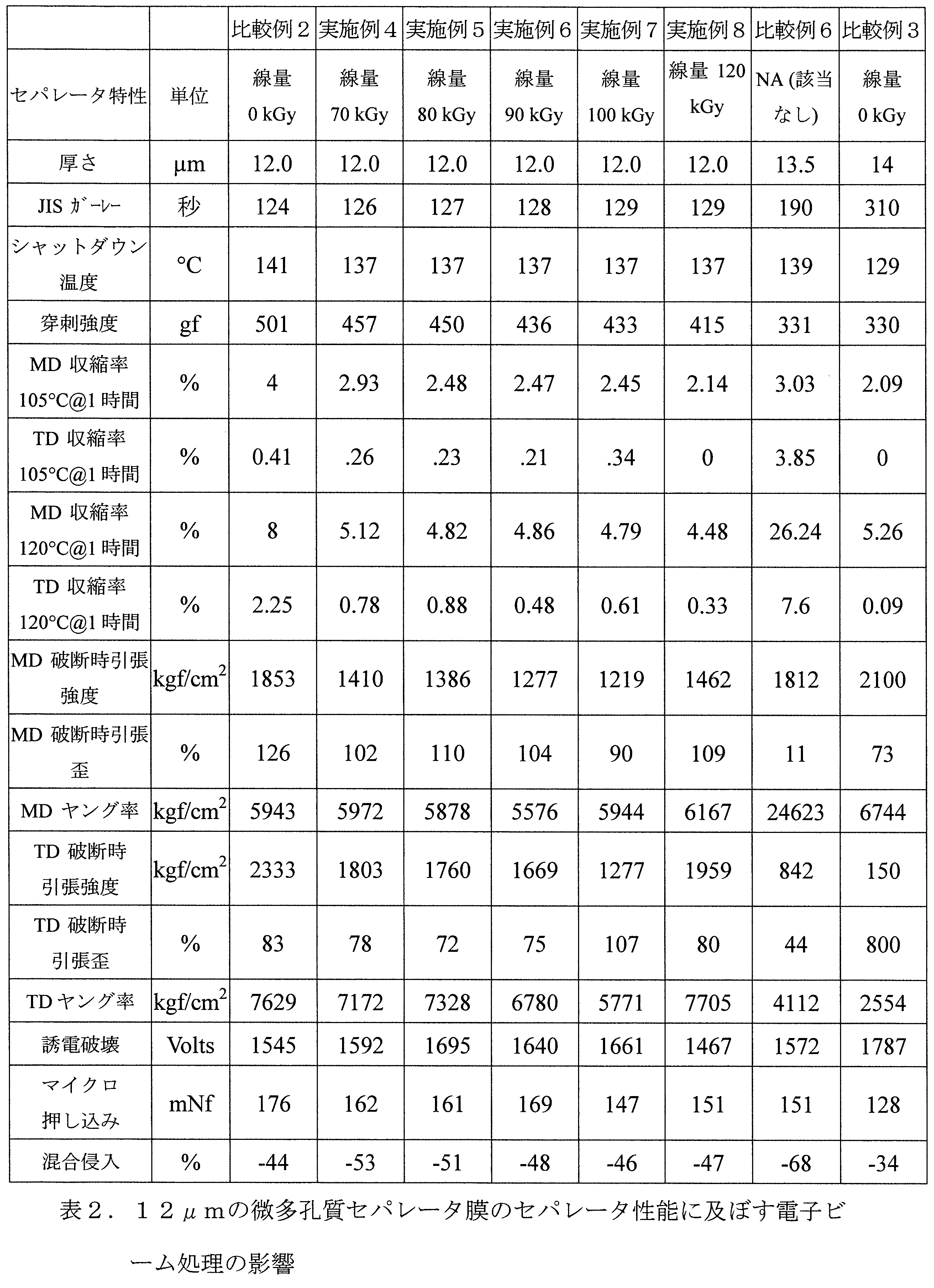
以下の表1および表2は、約9μmおよび12μmの範囲の厚さを有する様々なセパレータ膜の性能データを列挙しており、そのいくつかは、電子ビーム処理された微多孔質セパレータ膜である。電子ビームの線量は、加速電圧180kVで70~120kGyの範囲であった。ライン速度は50フィート/分であり、フィルムは酸素レベルが10ppm未満に維持された窒素雰囲気中で処理された。 Tables 1 and 2 below list performance data for various separator membranes having thicknesses ranging from about 9 μm and 12 μm, some of which were microporous separator membranes that were electron beam treated. The electron beam doses ranged from 70 to 120 kGy at an accelerating voltage of 180 kV. The line speed was 50 feet/min, and the films were processed in a nitrogen atmosphere with oxygen levels maintained below 10 ppm.
表1において、特許例実施例1、2および3は、本発明の9μm(約9μm)の湿式プロセス微多孔質単層ポリエチレン電池セパレータ膜の例であり、gそれは、それぞれ70、80および90kGyの電子線量で処理された。比較例1および比較例5は、電子ビー
ム処理されていない9μm(約9μm)の湿式プロセス微多孔質単層ポリエチレン電池セパレータ膜である。比較例4は、e-ビーム処理されていない8.7μmの乾式プロセスのポリプロピレン含有PP/PE/PP三層微多孔質電池セパレータ膜である。
In Table 1, Patent Examples 1, 2 and 3 are examples of 9 μm (approximately 9 μm) wet process microporous monolayer polyethylene battery separator membranes of the present invention that were treated with electron doses of 70, 80 and 90 kGy, respectively. Comparative Examples 1 and 5 are 9 μm (approximately 9 μm) wet process microporous monolayer polyethylene battery separator membranes that were not e-beam treated. Comparative Example 4 is an 8.7 μm dry process polypropylene-containing PP/PE/PP trilayer microporous battery separator membrane that was not e-beam treated.
表2において、特許例実施例4、5、6、7および8は、本発明の12μmの湿式プロセス微多孔質単層ポリエチレン電池セパレータ膜の例であり、それは、それぞれ70、80、90、100および120kGyの電子線量で処理された。比較例2および比較例6は、それぞれ電子ビーム処理されていない、12μmおよび13.5μmの湿式プロセス微多孔質単層ポリエチレン電池セパレータ膜である。 比較例3は、電子ビーム処理され
ていない14μmの乾式プロセスのポリプロピレン含有PP/PE/PP三層微多孔質電池セパレータ膜である。
In Table 2, Patent Examples 4, 5, 6, 7 and 8 are examples of 12 μm wet process microporous monolayer polyethylene battery separator membranes of the present invention, which were treated with electron doses of 70, 80, 90, 100 and 120 kGy, respectively. Comparative Examples 2 and 6 are 12 μm and 13.5 μm wet process microporous monolayer polyethylene battery separator membranes, respectively, that are not e-beam treated. Comparative Example 3 is a 14 μm dry process polypropylene-containing PP/PE/PP trilayer microporous battery separator membrane that is not e-beam treated.
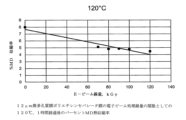
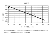
PE微多孔質膜の熱的性能を改変するために電子ビーム放射を使用する本発明の方法は、機械方向(MD)および横方向(TD)収縮率の減少を達成した。図5は、電子ビーム処理線量の関数としての12μmの微多孔質ポリエチレンセパレータ膜の1時間、105℃での%MD熱収縮率を示す。電子ビームの線量レベルは、70~120kGyの範囲である。120kGy電子ビーム線量で処理した微多孔質ポリエチレンセパレータ膜の%MD熱収縮率のレベルは、4%から2%に減少した。図6は、電子ビーム処理線量の関数としての、12μmの微孔性ポリエチレンセパレータ膜の1時間、120℃での%MD熱収縮率を示す。120kGyの電子ビーム線量で処理された微多孔質ポリエチレンセパレータ膜の%MD熱収縮率レベルは、8%から4.5%に減少した。 The method of the present invention using electron beam radiation to modify the thermal performance of PE microporous membranes achieved a reduction in machine direction (MD) and transverse direction (TD) shrinkage. Figure 5 shows the %MD heat shrinkage of 12 μm microporous polyethylene separator membranes at 105°C for 1 hour as a function of electron beam treatment dose. The electron beam dose levels range from 70 to 120 kGy. The %MD heat shrinkage level of the microporous polyethylene separator membranes treated with 120 kGy electron beam dose decreased from 4% to 2%. Figure 6 shows the %MD heat shrinkage of 12 μm microporous polyethylene separator membranes at 120°C for 1 hour as a function of electron beam treatment dose. The %MD heat shrinkage level of the microporous polyethylene separator membranes treated with 120 kGy electron beam dose decreased from 8% to 4.5%.
図7および図8は、70kGy~120kGyの範囲の電子ビーム線量での電子ビーム処理PEセパレータ膜の横方向(TD)熱収縮試験の結果を示す。%TDの熱収縮率は、120℃でほぼ0に減少した。 Figures 7 and 8 show the results of transverse direction (TD) heat shrinkage testing of e-beam treated PE separator membranes at e-beam doses ranging from 70 kGy to 120 kGy. The %TD heat shrinkage was reduced to nearly 0 at 120°C.

熱収縮率の減少に加えて、e-ビーム放射はサーマルシャットダウンの開始温度に影響を及ぼす。図3は、電子ビーム線量の関数としての9μm微多孔質PEセパレータ膜のサーマルシャットダウン曲線を示す。サーマルシャットダウンの開始温度は、約143℃から139℃へ減少するのが観察される。 In addition to reducing the thermal shrinkage, e-beam radiation affects the onset temperature of thermal shutdown. Figure 3 shows the thermal shutdown curve for a 9 μm microporous PE separator membrane as a function of e-beam dose. The onset temperature of thermal shutdown is observed to decrease from approximately 143°C to 139°C.
電子ビームは、加速された電子がポリマー中の化学結合を破壊するのに十分なエネルギーを有するイオン化放射線の一種である。 電子ビーム放射によって生成される2つの一
般的なタイプの化学プロセスは、鎖切断および架橋である。これらのプロセスは、ポリマーが低エネルギー電子ビームを用いて照射されるときに同時に起こり得る。連鎖切断は、電子ビームが化学結合を破壊し、短縮されたポリマー鎖またはフラグメントにつながり得る1つ以上のフリーラジカルを生成する場合に起こる。同時に、低エネルギーの電子ビームは、ポリマー鎖に沿ってまたは架橋反応のための部位を生成するポリマー鎖の末端にフリーラジカルを生成することができる。図2は、1以上のポリマー鎖を化学的に一緒に結合させるために電子ビーム放射を用いて架橋された種々のポリマー鎖の模式図を示す。
Electron beam is a type of ionizing radiation in which accelerated electrons have enough energy to break chemical bonds in polymers. Two common types of chemical processes produced by electron beam radiation are chain scission and crosslinking. These processes can occur simultaneously when a polymer is irradiated with a low-energy electron beam. Chain scission occurs when the electron beam breaks chemical bonds and generates one or more free radicals that can lead to shortened polymer chains or fragments. At the same time, low-energy electron beams can generate free radicals along the polymer chain or at the end of the polymer chain that create sites for crosslinking reactions. Figure 2 shows a schematic diagram of various polymer chains that have been crosslinked using electron beam radiation to chemically bond one or more polymer chains together.
本発明のe-ビーム処理されたPE微多孔質セパレータ膜は、未処理のPEセパレータ膜よりもサーマルシャットダウンの開始が低い。セパレータ内のサーマルシャットダウンのより低い開始温度は、より高いサーマルシャットダウン温度を持つセパレータと比較して改善されたレベルの安全性を有する。サーマルシャットダウンの温度が低いことは、圧倒的に鎖切断に起因し得るが、その一方で、拡大され、広げられたサーマルシャットダウン・ウインドウは主に架橋によるものであり得る。ポリマーの種類、その分子量および分布、結晶化度、アモルファス含有量、および立体規則性などのパラメータを選択することによって、およびe-ビーム処理条件、例えば圧力、温度、気体雰囲気中の酸素の存在およびe-ビームの線量を選択することによって、連鎖切断対架橋活性の優位性をバランスさせることができる。電子ビームの線量は、加速電圧180kVで70~120kGyの範囲であった。ライン速度は50フィート/分であり、フィルムは酸素レベルが10ppm未満に維持された窒素雰囲気中で処理された。多くのポリマーは、架橋および切断の両方を受け、優勢なプロセスは、ポリマーの化学構造および形態、ならびに選択されたe-ビーム処理条件に依存する。 The e-beam treated PE microporous separator membranes of the present invention have a lower onset of thermal shutdown than untreated PE separator membranes. The lower onset temperature of thermal shutdown in the separator has an improved level of safety compared to separators with higher thermal shutdown temperatures. The lower temperature of thermal shutdown can be predominantly attributed to chain scission, while the enlarged and widened thermal shutdown window can be primarily due to crosslinking. The dominance of chain scission versus crosslinking activity can be balanced by selecting parameters such as the type of polymer, its molecular weight and distribution, crystallinity, amorphous content, and stereoregularity, and by selecting the e-beam processing conditions, such as pressure, temperature, presence of oxygen in the gas atmosphere, and e-beam dose. The electron beam dose ranged from 70 to 120 kGy at an accelerating voltage of 180 kV. The line speed was 50 feet/min, and the films were processed in a nitrogen atmosphere with oxygen levels maintained below 10 ppm. Many polymers undergo both crosslinking and scission, and the process that prevails depends on the chemical structure and morphology of the polymer and the e-beam processing conditions selected.
ポリエチレン微多孔質電池セパレータ膜のサーマルシャットダウンは、PEの分子量および結晶化度に依存し得、ポリマーの融点またはその付近で起こり、それは典型的には130~145℃の範囲である。電池セパレータ膜においてサーマルシャットダウンが起こると、電気抵抗(ER)は約1,000~10,000オーム・cm2オーダーの高いイオン抵抗レベルに達し、セパレータ膜は‘シャットダウン’すると言われる。セパレータ膜が180℃以上の温度で電気抵抗1000~10,000オーム・cm2を超える高レベルを維持する場合、これは‘持続的高温サーマルシャットダウン’と呼ばれる。 Thermal shutdown of polyethylene microporous battery separator membranes may depend on the molecular weight and crystallinity of the PE and occurs at or near the melting point of the polymer, which is typically in the range of 130-145°C. When thermal shutdown occurs in a battery separator membrane, the electrical resistance (ER) reaches a high ionic resistance level, on the order of about 1,000-10,000 ohm- cm2 , and the separator membrane is said to 'shut down'. If the separator membrane maintains a high level of electrical resistance, above 1000-10,000 ohm- cm2 , at temperatures of 180°C or greater, this is referred to as a 'sustained high temperature thermal shutdown'.
ポリエチレン微多孔質電池セパレータ膜の場合、電池温度が150℃に上昇すると、ポリエチレンセパレータ膜の溶融完全性が失われるために、場合によっては、サーマルシャットダウンが失われる可能性がある。ポリエチレン微多孔質電池セパレータのサーマルシャットダウン・ウインドウは、5-15℃のオーダーであり、狭いサーマルシャットダウン・ウインドウとみなされる。サ-マルシャットダウン・ウインドウは、PEとPPとをブレンドすることにより、ポリプロピレンなどのより高い溶融温度のポリマーとポリエチレンとを組み合わせることによって調整することができる。しかし、PPはPEとの相溶性が低く、PPとPEの2つのポリマーは混ざり合い難い傾向にある。PPとPEをセパレータに組み込む別の方法は、PPの1つ以上の層をPEの1つ以上の層と積層して、積み重ねられた積層構造の膜を作ることによる。 For polyethylene microporous battery separator membranes, thermal shutdown may be lost in some cases when the battery temperature increases to 150°C due to loss of melt integrity of the polyethylene separator membrane. The thermal shutdown window for polyethylene microporous battery separators is on the order of 5-15°C, which is considered a narrow thermal shutdown window. The thermal shutdown window can be adjusted by combining polyethylene with a higher melting temperature polymer, such as polypropylene, by blending PE with PP. However, PP has low compatibility with PE, and the two polymers tend not to mix well. Another way to incorporate PP and PE into the separator is by laminating one or more layers of PP with one or more layers of PE to create a stacked laminated membrane.
積層PPおよびPEを含有するセパレータの好ましい構成は、‘ポリプロピレン/ポリエチレン/ポリプロピレン’三層セパレータ膜構成であり、内側ポリエチレン層が約130~135℃の早期サーマルシャットダウンに寄与し、ポリプロピレン外側層が 約16
5℃でのより高いサーマルシャットダウンに寄与する。ポリプロピレン/ポリエチレン/ポリプロピレン(PP/PE/PP)三層電池セパレータ膜のサーマルシャットダウンは
、例えば、乾式プロセスの内側PE層のために、場合によっては130℃の開始サーマルシャットダウンを有することがあるが、PP層のために165℃まで完全には溶融しないことがある。
A preferred configuration for a separator containing laminated PP and PE is a 'polypropylene/polyethylene/polypropylene' three layer separator membrane configuration, with the inner polyethylene layer contributing to early thermal shutdown at about 130-135°C and the polypropylene outer layer contributing to early thermal shutdown at about 16
This contributes to a higher thermal shutdown at 5° C. The thermal shutdown of a polypropylene/polyethylene/polypropylene (PP/PE/PP) tri-layer battery separator membrane, for example, may in some cases have an onset thermal shutdown of 130° C. due to the dry process inner PE layer, but may not fully melt until 165° C. due to the PP layer.
図4は、PP含有膜比較例4、PP/PE/PPセパレータ膜のサーマルシャットダウン曲線を包含する。比較例4の持続的なサーマルシャットダウン・ウインドウは130.5℃から起こり、180℃以上のPP層の完全性の喪失まで続く。PP/PE/PP三層電池セパレータ膜のサーマルシャットダウン・ウインドウは、放射処理されていないPEセパレータ膜比較例1よりも広い。PP含有比較例4三層電池セパレータ膜は、リチウムイオン充電式電池において良好な熱的性能を有する。 Figure 4 contains the thermal shutdown curves for the PP-containing membrane Comparative Example 4, a PP/PE/PP separator membrane. The sustained thermal shutdown window for Comparative Example 4 begins at 130.5°C and continues until loss of integrity of the PP layer above 180°C. The thermal shutdown window for the PP/PE/PP trilayer battery separator membrane is wider than the non-irradiated PE separator membrane Comparative Example 1. The PP-containing Comparative Example 4 trilayer battery separator membrane has good thermal performance in lithium-ion rechargeable batteries.
PE微多孔質電池セパレータ膜が熱的性能の点で三層のPP/PE/PP微多孔質電池セパレータ膜と競合するためには、PEサーマルシャットダウン・ウインドウを広げる必要がある。PE微多孔質電池セパレータ膜の電子ビーム処理は、低いシャットダウンの開始温度を達成し、PP含有膜に類似した所望の広がったサーマルシャットダウン・ウインドウを有するより高い溶融完全性PE層を生成する。電子処理されたPE微多孔質電池セパレータ膜は、広いサーマルシャットダウン・ウインドウを有し、充電式リチウムイオン電池におけるPP含有電池セパレータ膜と同様に180℃以上の温度まで高温溶融完全性を維持する。 For PE microporous battery separator membranes to compete in thermal performance with trilayer PP/PE/PP microporous battery separator membranes, the PE thermal shutdown window needs to be extended. Electron beam treatment of PE microporous battery separator membranes achieves low shutdown onset temperatures and produces a higher melt integrity PE layer with the desired extended thermal shutdown window similar to PP-containing membranes. Electron-treated PE microporous battery separator membranes have a wide thermal shutdown window and maintain high temperature melt integrity up to temperatures of 180°C or higher, similar to PP-containing battery separator membranes in rechargeable lithium ion batteries.
図3は、70~90kGyの範囲の電子線放射で処理された9μmセパレータ膜のサーマルシャットダウン曲線を示す。実施例1、実施例2および実施例3は、それぞれ70、80および90kGyのe-ビーム線量で処理された。サーマルシャットダウンの開始温度は、e-ビーム線量が増加するにつれて約142℃から137.5℃に減少した。 e
-ビーム線量が増加するにつれて、熱的遮断ウインドウが広げられる。図4は、実施例3のサーマルシャットダウン・ウインドウが、PP含有三層のPP/PE/PPセパレータ膜比較例4のものに類似する約180℃に及ぶことを示す。図9は、e-ビーム線量は70~120kGyの範囲にある、種々の12μm厚のPE微多孔質セパレータ膜についてのサーマルシャットダウン曲線を示している。e-ビーム線量が増加するにつれて、12μmのセパレータ膜のサーマルシャットダウン・ウインドウが高温で拡大される。
FIG. 3 shows the thermal shutdown curves for 9 μm separator membranes treated with e-beam radiation ranging from 70 to 90 kGy. Examples 1, 2, and 3 were treated with e-beam doses of 70, 80, and 90 kGy, respectively. The onset temperature of thermal shutdown decreased from approximately 142° C. to 137.5° C. as the e-beam dose increased.
As the e-beam dose increases, the thermal shutdown window is widened. Figure 4 shows that the thermal shutdown window of Example 3 extends to about 180°C, similar to that of the PP-containing trilayer PP/PE/PP separator membrane Comparative Example 4. Figure 9 shows the thermal shutdown curves for various 12 μm thick PE microporous separator membranes with e-beam doses ranging from 70 to 120 kGy. As the e-beam dose increases, the thermal shutdown window of the 12 μm separator membrane is widened at high temperatures.
実施例8は120kGyのe-ビーム線量で処理され、180℃以上に及ぶ広いサーマルシャットダウン・ウインドウを有する。図10は、実施例8および比較例2のサーマルシャットダウン曲線を示し、後者は電子ビーム処理されなかったPEセパレータ膜である。e-ビーム処理の有益な効果は、実施例8および比較例2を比較して示され、ここで、比較例2は約5℃の非常に狭いサーマルウインドウしか有さないが、一方で、実施例8は、比較例3のPP/PE/PP三層積層セパレータ膜のものと同様の拡大されたサーマルシャットダウン・ウインドウを有し、電子ビーム処理が1つ以上のPP層を含有する膜と同様のサーマルシャットダウン・ウインドウを有するPE膜を生成したことを示す。 Example 8 was treated with an e-beam dose of 120 kGy and has a wide thermal shutdown window spanning over 180°C. Figure 10 shows the thermal shutdown curves of Example 8 and Comparative Example 2, the latter of which is a PE separator membrane that was not e-beam treated. The beneficial effect of e-beam treatment is shown by comparing Example 8 and Comparative Example 2, where Comparative Example 2 has a very narrow thermal window of only about 5°C, while Example 8 has an expanded thermal shutdown window similar to that of the PP/PE/PP tri-laminate separator membrane of Comparative Example 3, indicating that e-beam treatment produced a PE membrane with a thermal shutdown window similar to that of membranes containing one or more PP layers.
PE微多孔質セパレータ膜のための本発明のe-ビーム処理は、サーマルシャットダウンの開始温度を下げ、サーマルシャットダウン・ウインドウを180℃以上に広げることの重要性を証明する。微多孔質セパレータ膜のe-ビーム処理は、充電式リチウムイオン電池における改善されたレベルの安全性能を持つより高い溶融完全性のセパレータ膜を生成する。 The inventive e-beam treatment of PE microporous separator membranes demonstrates the importance of lowering the onset temperature of thermal shutdown and extending the thermal shutdown window to 180°C or more. E-beam treatment of microporous separator membranes produces separator membranes of higher melt integrity with improved levels of safety performance in rechargeable lithium ion batteries.
セパレータ膜の機械的強度に及ぼす低エネルギー電子ビーム処理の効果を、温度の関数として膜の機械的強度を測定する熱機械分析(TMA)を用いて検討した。TMAが‘引っ張り’モードで行われる場合、試験サンプルは一定の張力下に保持され、一方、温度は室温から高温に上昇させられる。e-ビーム処理PE微多孔膜のTMA試験は、熱破裂温
度のより高い温度へのシフトを示した(図11参照)。未処理比較例2は141℃付近で急激に溶融し、物理的寸法の急激な変化を経る。
The effect of low energy electron beam treatment on the mechanical strength of separator membranes was investigated using thermomechanical analysis (TMA), which measures the mechanical strength of the membrane as a function of temperature. When TMA is performed in 'tensile' mode, the test sample is held under constant tension while the temperature is increased from room temperature to an elevated temperature. TMA testing of e-beam treated PE microporous membranes showed a shift in the thermal burst temperature to higher temperatures (see Figure 11). The untreated Comparative Example 2 melts rapidly near 141°C and undergoes a rapid change in physical dimensions.
e-ビーム処理された試料の実施例6および実施例7は、90および100kGyでそれぞれ処理され、異なる方法で適用された応力に応答した。実施例6および実施例7は、温度が上昇するにつれてより緩やかな寸法変化率を示し、e-ビーム処理による膜の寸法変化に対する耐性が高いことを示している。強度の増加は、PEポリマー膜における架橋の発生によるものであり得、破裂温度の上方シフトは、膜がその溶融温度付近でより強いことを示し得ると考えられる。 The e-beam treated samples, Examples 6 and 7, were treated at 90 and 100 kGy, respectively, and responded to the applied stress in different ways. Examples 6 and 7 showed a slower rate of dimensional change as the temperature increased, indicating that the membranes were more resistant to dimensional changes due to e-beam treatment. It is believed that the increase in strength may be due to the occurrence of crosslinking in the PE polymer membrane, and the upward shift in burst temperature may indicate that the membrane is stronger near its melting temperature.
e-ビーム処理は、所望の熱的性能に応じてPE微多孔質セパレータ膜をより高くまたはより低く移動させることによって、PE微多孔質膜の熱破裂温度を微調整する方法を提供する。増加した高温溶融強度は、熱暴走事象の場合に陰極と陽極の分離を維持するのに役立つことがある。 E-beam processing provides a way to fine-tune the thermal burst temperature of the PE microporous separator membrane by moving it higher or lower depending on the desired thermal performance. The increased high temperature melt strength can help maintain separation of the cathode and anode in the event of a thermal runaway event.
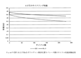
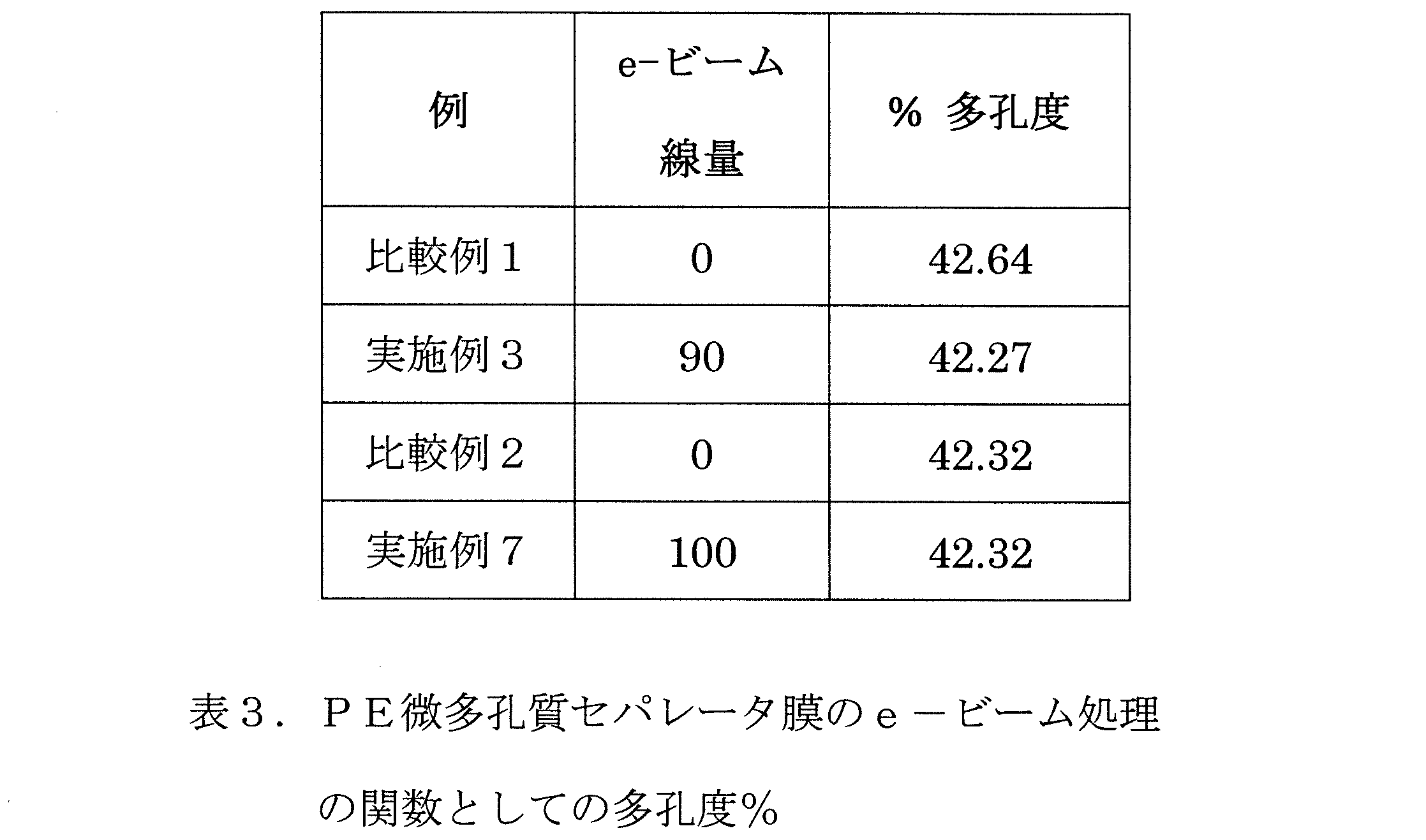
微多孔質PEセパレータ膜の細孔径分布に対する電子ビーム放射の影響を図12および図13に示す。9μmおよび12μmのPE微孔質セパレータ膜の両方に対するe-ビーム処理に起因する細孔径分布に統計的差はない。表3は、多孔度データのパーセントを示し、e-ビーム放射が微多孔質セパレータ膜の多孔度に影響しないことを示す。 The effect of electron beam radiation on the pore size distribution of microporous PE separator membranes is shown in Figures 12 and 13. There is no statistical difference in the pore size distribution resulting from e-beam treatment for both 9 μm and 12 μm PE microporous separator membranes. Table 3 shows the percentage of porosity data and indicates that e-beam radiation does not affect the porosity of the microporous separator membranes.
e-ビーム処理されたPE微多孔質セパレータ膜の表面形態は、図15に表わした走査型電子顕微鏡写真に示されている。低エネルギーe-ビーム処理は、膜の表面または細孔を損傷しなかった(未処理の膜を表わした図14も参照)。e-ビーム処理は、低いe-ビーム線量レベルで行われ、PE微多孔質セパレータ膜の表面または内部細孔構造には劣化は観察されなかった。 The surface morphology of the e-beam treated PE microporous separator membrane is shown in the scanning electron micrograph depicted in Figure 15. The low energy e-beam treatment did not damage the membrane's surface or pores (see also Figure 14, which depicts an untreated membrane). The e-beam treatment was performed at low e-beam dose levels, and no degradation was observed on the surface or internal pore structure of the PE microporous separator membrane.
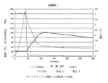
電子ビーム処理は、微多孔質電池セパレータ膜の電解質濡れを改善する追加の利点を有する。PE微多孔質電池セパレータ膜の低e-ビーム放射は、セパレータ膜の表面および微多孔質セパレータ膜の内部細孔構造全体の両方の上における電解液の接触角を減少させることによって、リチウムイオン電池における電解質濡れを変化させ得る。より低い接触角は、より高い電解質吸収を示し、リチウムイオン電池の容量を改善することを導き得る。表4は、9μmのPE微多孔質セパレータ膜の接触角測定結果を列挙する。実施例3の
表面上の電解質プロピレンカーボネートを用いた接触角を90kGyの線量でe-ビーム放射に曝露した場合、接触角が75.8°から60.2°に減少し、それは、20%減少である。
Electron beam treatment has the added benefit of improving electrolyte wetting of microporous battery separator membranes. Low e-beam radiation of PE microporous battery separator membranes can change electrolyte wetting in lithium ion batteries by decreasing the contact angle of the electrolyte on both the separator membrane surface and throughout the microporous separator membrane's internal pore structure. Lower contact angles indicate higher electrolyte absorption, which can lead to improved capacity of lithium ion batteries. Table 4 lists the contact angle measurements of 9 μm PE microporous separator membranes. When the contact angle with electrolyte propylene carbonate on the surface of Example 3 was exposed to e-beam radiation at a dose of 90 kGy, the contact angle decreased from 75.8° to 60.2°, which is a 20% decrease.

過充電、サイクリング、ホットボックスおよびボールクラッシュ安全性試験を、本発明のe-ビーム処理されたPE微多孔質膜を含有する電池セルで行実施例った。e-ビーム放射膜で行った過充電試験の間、完全に充電されたセルは5Vで3Cの充電速度に付される。過充電試験に合格するための要件は、爆発しないか、または電池に火災が発生しないことである。比較例1と実施例3の過充電試験結果がそれぞれ図16および図17に示されており、実施例3に対するシャットダウン後の過充電時の残留電流が、非電子ビーム放射膜比較例1と比較してより低いことを示しており、これは過充電性能の改善である。 Overcharge, cycling, hot box and ball crush safety tests were performed on battery cells containing the e-beam treated PE microporous membrane of the present invention. During the overcharge test performed with the e-beam radiated membrane, the fully charged cell is subjected to a charge rate of 3C at 5V. The requirement for passing the overcharge test is that there is no explosion or fire in the battery. The overcharge test results for Comparative Example 1 and Example 3 are shown in Figures 16 and 17, respectively, and show that the residual current upon overcharge after shutdown for Example 3 is lower compared to the non-e-beam radiated membrane Comparative Example 1, which is an improvement in overcharge performance.
実施例3は150℃で1時間ホットボックス試験を行った。ホットボックス試験後のe-ビーム処理された膜の外観を観察するために、電池セルを冷却して開いた。図18は、プリズム状の電池から除去した後の実施例3の写真である。電子ビーム処理した実施例3は無傷の片で陰極から剥ぎ取られ、これは溶融完全性を失っておらず、その物理的寸法を維持していたことを示している。対照的に、図19は、未処理PE膜比較例1が陰極に完全に付着したことを示している。比較例1は陰極から分離または剥離することができず、ホットボックス試験中に高温を経た結果、未処理のPE膜が陰極に対して溶けていることが示している。 Example 3 was subjected to hot box testing at 150°C for 1 hour. The battery cell was cooled and opened to observe the appearance of the e-beam treated film after hot box testing. Figure 18 is a photograph of Example 3 after removal from the prismatic battery. The e-beam treated Example 3 peeled away from the cathode in an intact piece, indicating that it had not lost its fusion integrity and maintained its physical dimensions. In contrast, Figure 19 shows that the untreated PE film Comparative Example 1 was completely attached to the cathode. Comparative Example 1 could not be separated or peeled away from the cathode, indicating that the untreated PE film had melted to the cathode as a result of the high temperatures experienced during the hot box testing.
ボールクラッシュ試験の結果は、温度と電圧が測定される間に、時間の関数としてプロットされ、図20と21に示される。ボールクラッシュ試験は、内部短絡試験の一種で、球形のプローブが電池セルの外面に押し付けられ、増加する負荷が加えられる。両方のサンプルがボールクラッシュ試験に合格し、e-ビーム処理が、リチウムイオン電池のPE微多孔質セパレータ膜の安全性能に悪影響を及ぼさなかったことが示された。 The results of the ball crush test, plotted as a function of time while temperature and voltage were measured, are shown in Figures 20 and 21. The ball crush test is a type of internal short circuit test in which a spherical probe is pressed against the outer surface of the battery cell and an increasing load is applied. Both samples passed the ball crush test, indicating that the e-beam treatment did not adversely affect the safety performance of the PE microporous separator membrane in lithium-ion batteries.
電池サイクル試験の結果は図22に示され、実施例3は比較例1よりも容量が高く、これはe-ビーム処理の結果として電解質吸収が増加したことに起因するものであり得る。
e-ビーム処理の間、ポリエチレンは酸化を含む一連の化学反応を受け、1720cm-1でFTIR分析によって検出可能なカルボニル基を生成し得る。カルボニル基は、ポリエチレンをより親水性にすることができ、それは、PE膜がより多くの電解質を吸収し、より高い容量をもたらすことを導き得る。実施例3は約200サイクル繰り返され、一貫した非放射処理の比較例1よりも高い容量を示している。
The results of the battery cycling test are shown in FIG. 22, and Example 3 has a higher capacity than Comparative Example 1, which can be attributed to the increased electrolyte absorption as a result of the e-beam treatment.
During e-beam treatment, polyethylene undergoes a series of chemical reactions including oxidation, which can produce carbonyl groups detectable by FTIR analysis at 1720 cm -1 . The carbonyl groups can make polyethylene more hydrophilic, which can lead to the PE membrane absorbing more electrolyte and resulting in higher capacity. Example 3 has been cycled for about 200 times and shows a higher capacity than the consistent non-radiation treated Comparative Example 1.
試験方法
厚さ
厚さは、試験方法ASTM D374によって、Emveco Microgage 210-A精密マイクロメータ厚みテスターを使用して測定される。厚さ値は、ミクロン、μmの単位で報告される。
Test Methods Thickness Thickness is measured using an Emveco Microgage 210-A precision micrometer thickness tester according to test method ASTM D374. Thickness values are reported in microns, μm.
穿刺強度
試験サンプルは、最初に、最低20分間73.4℃および50%の相対湿度に予備調整される。インストロンモデル4442が、ASTM D3763に基づいて試験サンプルの穿刺強度を測定するために使用される。11/4”×40”連続試料の斜め方向に30回
測定し平均した。針は半径0.5mmである。下降速度は25mm/分である。フィルムは、Oリングを利用して試験サンプルを定位置にしっかりと保持する締付け器具でしっかりと保持される。この固定された領域の直径は25mmである。ニードルによって穿孔されたフィルムの変位(mm)は、試験されたフィルムによって生じる抵抗力(グラム力)に対して記録される。最大抵抗力は、グラム力(gf)単位の穿刺強度である。この試験方法によって荷重-変位プロットが作られる。
Puncture Strength Test samples are first preconditioned at 73.4°C and 50% relative humidity for a minimum of 20 minutes. An Instron Model 4442 is used to measure the puncture strength of the test samples according to ASTM D3763. Thirty measurements were taken diagonally on a 1¼″×40″ continuous sample and averaged. The needle has a 0.5 mm radius. The descent rate is 25 mm/min. The film is held securely in a clamping fixture that utilizes an O-ring to hold the test sample securely in place. The diameter of this clamped area is 25 mm. The displacement (mm) of the film punctured by the needle is recorded against the force (gram force) exerted by the tested film. The maximum force is the puncture strength in grams force (gf). A load-displacement plot is generated by this test method.
細孔径分布
Porous Materials, Inc. (PMI)社を通じて入手可能なアクアポア ポロシメータ(Aquapore Porosimeter)を使用して測定される。細孔径は、μm単位で表示される。
Pore size distribution
Pore size is measured using an Aquapore Porosimeter available through Porous Materials, Inc. (PMI). Pore size is reported in μm.
多孔度
微多孔質フィルム試料の多孔度は、ASTM法D-2873を使用して測定され、微多孔質膜のボイドスペース・パーセントとして定義される。
Porosity The porosity of the microporous film samples was measured using ASTM method D-2873 and is defined as the percent void space of the microporous membrane.
TDおよびMD引張強度
引張強度が、機械方向(MD)と横方向(TD)に沿って、ASTM D-882法によってInstron Model 4201を使用して測定される。
TD and MD Tensile Strength Tensile strength is measured along the machine direction (MD) and transverse direction (TD) using an Instron Model 4201 according to ASTM D-882 method.
電気抵抗(ER)(イオン抵抗、IRとしても知られる)
電気抵抗は、電解質を充填したセパレータのオーム・cm2の抵抗値で定義される。電気抵抗の単位はオーム・cm2である。セパレータ抵抗は、完成した材料からセパレータの小片を切断し、次にそれらを2つの遮断電極の間に配置することによって特徴付けられる。セパレータは、容積比3:7のEC/EMC溶媒中の1.0MのLiPF6塩を持つ電池電解質で飽和される。セパレータのオーム(Ω)での抵抗(R)は、4プローブACインピーダンス技術によって測定される。電極/セパレータ界面の測定誤差を低減するために、より多くの層を追加することによって多数の測定が必要となる。多数の層の測定値に基づいて、電解質で飽和されたセパレータの電気(イオン)抵抗Rs(Ω)は、式Rs=psl/Aによって計算され、psはセパレータのΩ-cmのイオン抵抗率で、Aはc
m2単位の電極面積であり、lはcm単位のセパレータの厚さである。比ps/Aは、多数層(Δδ)のセパレータ抵抗(ΔR)の変化、それはΔR/Δδで表わされ、に対して計算された勾配である。
Electrical Resistance (ER) (also known as Ionic Resistance, IR)
Electrical resistance is defined as the resistance value in ohms- cm2 of the separator filled with electrolyte. The unit of electrical resistance is ohms- cm2 . The separator resistance is characterized by cutting small pieces of separator from the finished material and then placing them between two blocking electrodes. The separator is saturated with battery electrolyte with 1.0 M LiPF6 salt in EC/EMC solvent with a volume ratio of 3:7. The resistance (R) in ohms (Ω) of the separator is measured by a four-probe AC impedance technique. To reduce the measurement error of the electrode/separator interface, multiple measurements are required by adding more layers. Based on the measurements of multiple layers, the electrical (ionic) resistance Rs (Ω) of the separator saturated with electrolyte is calculated by the formula Rs = ps l/A, where ps is the ionic resistivity of the separator in Ω-cm and A is the capacitance of the separator.
where m is the electrode area in m2 and l is the separator thickness in cm. The ratio p s /A is the calculated slope for the change in separator resistance (ΔR) for multiple layers (Δδ), which is expressed as ΔR/Δδ.
熱収縮率
収縮率試験は、10cm×10cmの膜サンプルをマニラフォルダに置き、次にこれをクリップを使用してオーブン中に吊るすことによって測定する。収縮率は、試験サンプルを105℃のオーブンに1時間入れた前後のMDおよびTD方向の収縮率をキャリパーを使用して測定した。収縮率はまた、第2の試験サンプルを120℃のオーブンに1時間入れた前後のMD方向およびTD方向の収縮率をキャリパーを用いて測定した。収縮率は、改変したASTM 2732-96を使用して、%MD収縮率および%TD収縮率として表される。
Heat Shrinkage Shrinkage testing is measured by placing a 10 cm x 10 cm membrane sample in a manila folder, which is then hung in an oven using clips. Shrinkage was measured using calipers in the MD and TD directions before and after placing a test sample in an oven at 105°C for 1 hour. Shrinkage was also measured using calipers in the MD and TD directions before and after placing a second test sample in an oven at 120°C for 1 hour. Shrinkage is expressed as % MD shrinkage and % TD shrinkage using a modified ASTM 2732-96.
誘電破壊(DB)
誘電破壊(DB)は、セパレータの電気絶縁性の測定値である。試料の誘電破壊が観察されるまで、電圧をセパレータ膜に6,000V/秒のランプ速度で印加する。高いDBは、セパレータが良好な巻線収率および低いHiPot故障率を有するであろうことを示す。
Dielectric Breakdown (DB)
Dielectric breakdown (DB) is a measurement of the electrical insulation of the separator. A voltage is applied to the separator film at a ramp rate of 6,000 V/sec until dielectric breakdown of the sample is observed. A high DB indicates that the separator will have good winding yield and low HiPot failure rate.
ホット電気抵抗(ER)
ホット電気抵抗は、温度が60℃/分の速度で直線的に増加する間の50ポンドの圧力下でのセパレータフィルムの抵抗の尺度である。セパレータの直径3/8”の一片は、電解液で飽和され、AlまたはCuから作られた2つの電極ディスクの間に挟まれる。インピーダンスとして測定された抵抗の上昇は、セパレータ膜の溶融または“シャットダウン”による細孔構造の崩壊に相当する。セパレータ膜が高温で高レベルの電気抵抗を持続する場合、これはセパレータ膜がバッテリの電極の短絡を防止し得ることを示している。
Hot Electrical Resistance (ER)
Hot electrical resistance is a measure of the resistance of a separator film under 50 pounds of pressure while the temperature is increased linearly at a rate of 60°C/min. A 3/8" diameter piece of separator is saturated with electrolyte and sandwiched between two electrode disks made from Al or Cu. An increase in resistance, measured as impedance, corresponds to the collapse of the pore structure due to melting or "shutdown" of the separator membrane. If the separator membrane maintains a high level of electrical resistance at high temperatures, this is an indication that the separator membrane can prevent shorting of the electrodes of the battery.
ガーレー(Gurley)
ガーレー(Gurley)は、日本工業規格(JIS Gurley)JIS P8117として定義されており、OHKEN透過性試験機を使用して測定された透過性試験である。JIS Gurleyは、100ccの空気が4.8インチの一定水圧で1平方インチのフィルムを通過するのに必要な時間(秒)である。
Gurley
Gurley is defined as Japanese Industrial Standard (JIS) Gurley JIS P8117 and is a permeability test measured using an OHKEN permeability tester. JIS Gurley is the time (seconds) required for 100 cc of air to pass through 1 square inch of film at a constant water pressure of 4.8 inches.
混合侵入
混合侵入とは、陰極と陽極の材料の間に配置されたときにセパレータを通って短絡するのに必要な力である。この試験は、電池組立中にセパレータが短絡する傾向を示すために使用される。この方法の詳細は、US2010/209758に記載されている。
Mixed Penetration Mixed penetration is the force required to short through a separator when placed between cathode and anode materials. This test is used to indicate the tendency of a separator to short during battery assembly. Details of this method are described in US 2010/209758.
マイクロ押し込み
マイクロ押し込み(マイクロ侵入としても知られている)は、微細なミクロンの円錐形の圧子先端が非導電性フィルムサンプルを貫通し、電気抵抗の突然の低下によって定義されるように試験台上の導電性基板と接触する最大の力である。試験方法は、米国特許出願第2014/0090480号に記載されている。それはmNfの単位で表される。
Microindentation Microindentation (also known as micropenetration) is the maximum force at which a fine micron conical indenter tip penetrates a non-conductive film sample and makes contact with a conductive substrate on a test stand as defined by a sudden drop in electrical resistance. The test method is described in U.S. Patent Application Publication No. 2014/0090480. It is expressed in units of mNf.
接触角測定
接触角は、Kruss Drop Shape Analyzerを使用して測定した。接触角試験に用いた電解
質は、無水プロピレンカーボネート(PC)であった。PCの3μLの液滴を、慎重かつ穏やかにセパレータ試験サンプルの表面上に分注した。接触角は、PCの液滴の塗布の3秒以内に測定した。接触角は、度の単位で報告される。
Contact Angle Measurements Contact angles were measured using a Kruss Drop Shape Analyzer. The electrolyte used for contact angle testing was anhydrous propylene carbonate (PC). A 3 μL drop of PC was carefully and gently dispensed onto the surface of the separator test sample. Contact angles were measured within 3 seconds of application of the drop of PC. Contact angles are reported in degrees.
少なくとも選択された実施態様、側面または目的によれば、本出願または本発明は、新規または改善されたセパレータ膜、セパレータ、かかるセパレータを包含する電池、かかる膜および/またはセパレータの製造方法、および/またはかかる膜および/またはセパレータの使用方法を対象にする。少なくとも1つの特定の実施態様によれば、本発明は、イオン化放射で処理された微多孔質ポリオレフィン、ポリエチレン(PE)、コポリマー
および/またはポリマーブレンド(例えば、PEとポリプロピレン(PP)などの別のポリマーを含むコポリマーまたはブレンド)二次または充電式リチウム電池用の電池セパレータおよび/またはイオン化放射処理された微多孔質電池セパレータを製造する方法を対象にする。
According to at least selected embodiments, aspects or objectives, the present application or invention is directed to new or improved separator membranes, separators, batteries incorporating such separators, methods of making such membranes and/or separators, and/or methods of using such membranes and/or separators. According to at least one particular embodiment, the present invention is directed to a microporous polyolefin, polyethylene (PE), copolymer and/or polymer blend (e.g., a copolymer or blend including PE and another polymer such as polypropylene (PP)) battery separator for secondary or rechargeable lithium batteries treated with ionizing radiation and/or a method of making an ionizing radiation treated microporous battery separator.
本発明の微多孔質膜または電池セパレータは、サーマルシャットダウンのより低い開始温度を提供することができ、高温で物理的、寸法的および機械的完全性が維持される拡大されたサーマルシャットダウン・ウインドウを有することができ、充電式リチウム電池の電池安全性能を改善することができ、ポリプロピレンベースの三層製品の高温性能を有する処理されたポリエチレンセパレータ膜(一例として、ポリエチレン層を間に有する2つのポリプロピレン層からなる三層膜)を提供し得、熱収縮率を低減して、熱安定性と高温物理的完全性の両方をもたらし、それは、電池システムの陰極および陽極間の分離を維持し、充電式または二次リチウム電池、および/またはそれらの組み合わせにおける熱暴走事象を回避し得るのに重要であり得る。 The microporous membrane or battery separator of the present invention can provide a lower onset temperature of thermal shutdown, can have an extended thermal shutdown window where physical, dimensional and mechanical integrity is maintained at high temperatures, can improve battery safety performance of rechargeable lithium batteries, can provide a treated polyethylene separator membrane with the high temperature performance of polypropylene-based tri-layer products (an example being a tri-layer membrane made of two polypropylene layers with a polyethylene layer between them), can reduce heat shrinkage and provide both thermal stability and high temperature physical integrity, which can be important in maintaining separation between the cathode and anode of a battery system and avoiding thermal runaway events in rechargeable or secondary lithium batteries, and/or combinations thereof.
微多孔質ポリエチレン電池セパレータのイオン化放射処理は、サーマルシャットダウンの開始温度を低下させる方法を提供する。さらに、イオン化放射で処理された微孔性ポリエチレン電池セパレータ膜は、微多孔質セパレータ膜の物理的、寸法的および機械的完全性がより高い温度で維持される拡大されたサーマルシャットダウン・ウインドウを有する。本発明のイオン化放射処理されたセパレータ膜の拡大された高温寸法の完全性は、充電式リチウムイオン電池の電池安全性能を改善する。 Ionizing radiation treatment of microporous polyethylene battery separators provides a method to reduce the onset temperature of thermal shutdown. Additionally, microporous polyethylene battery separator membranes treated with ionizing radiation have an extended thermal shutdown window in which the physical, dimensional and mechanical integrity of the microporous separator membrane is maintained at higher temperatures. The extended high temperature dimensional integrity of the ionizing radiation treated separator membranes of the present invention improves the battery safety performance of rechargeable lithium ion batteries.
加えて、本発明のイオン化放射処理されたセパレータ膜の拡大された高温寸法の完全性は、ポリプロピレンベースの三層製品(一例として、間にポリエチレン層を有する2つのポリプロピレン層からなる三層膜)の高温性能に近づく。加えて、本発明の電池セパレータ膜は、熱収縮率を低減し、熱安定性および高温物理的完全性の両方をもたらし、それは、電池システムにおける陰極および陽極の分離を維持し、充電式または二次リチウム電池の熱暴走事象を回避するために重要であり得る。 In addition, the enhanced high temperature dimensional integrity of the ionizing radiation treated separator membranes of the present invention approaches the high temperature performance of polypropylene based tri-layer products (as an example, a tri-layer membrane consisting of two polypropylene layers with a polyethylene layer in between). In addition, the battery separator membranes of the present invention reduce thermal shrinkage and provide both thermal stability and high temperature physical integrity, which can be important for maintaining separation of cathodes and anodes in battery systems and avoiding thermal runaway events in rechargeable or secondary lithium batteries.
少なくとも選択された実施態様、側面、または目的に応じて、本出願または本発明は、新規なまたは改良されたまたは改変されたセパレータ膜、セパレータ、かかるセパレータを包含する電池、かかる膜および/またはセパレータの製造方法、および/またはかかる膜および/またはセパレータを使用する方法を提供し得るか、対象にする。少なくとも1つの特定の実施態様によれば、本発明は、ポリオレフィン、ポリエチレン(PE)、ポリプロピレン(PP)、コポリマーおよび/またはポリマーブレンド(例えば、PEおよび例えば、ポリプロピレン(PP)などの別のポリマーを含むコポリマーまたはブレンド)膜、微多孔質膜、セパレータ膜、電池セパレータ、および/または二次電池または充電式リチウム電池用の微多孔質電池セパレータ、および/またはイオン化放射処理膜、微多孔質膜、セパレータ膜、バッテリセパレータ、および/または微多孔質電池セパレータを製造しおよび/または使用する方法を対象にする。 Depending on at least selected embodiments, aspects, or objectives, the present application or invention may provide or is directed to new or improved or modified separator membranes, separators, batteries incorporating such separators, methods of making such membranes and/or separators, and/or methods of using such membranes and/or separators. According to at least one particular embodiment, the present invention is directed to polyolefin, polyethylene (PE), polypropylene (PP), copolymer and/or polymer blend (e.g., copolymer or blend including PE and another polymer such as, e.g., polypropylene (PP)) membranes, microporous membranes, separator membranes, battery separators, and/or microporous battery separators for secondary or rechargeable lithium batteries, and/or methods of making and/or using ionizing radiation treated membranes, microporous membranes, separator membranes, battery separators, and/or microporous battery separators.
本発明の微多孔質膜または電池セパレータは、サーマルシャットダウンのより低い開始温度を提供することができ、物理的、寸法的および機械的完全性が高温で維持される、拡大されたサーマルシャットダウン・ウインドウを有し得、より良好な耐酸化性を有し得、充電式リチウム電池の電池安全性を改善し得、処理されたポリエチレン、ポリプロピレンまたはポリオレフィンセパレータ膜を提供することができ、湿式プロセス製品に近いかまたはそれと同じ、またはそれを上回る性能を有する処理された乾式プロセス製品を提供することができ、より高温性能を持つ処理されたポリエチレン、ポリプロピレンまたはポリオレフィンセパレータ膜を提供することができ、ポリプロピレンベースの製品の高温性能を持つ処理されたポリエチレンセパレータ膜を提供することができ、ポリプロピレンベース
の多層または三層製品の高温性能を有する処理されたポリエチレンセパレータ膜を提供することができ(一例としてのみ、その間にポリエチレンまたはポリプロピレン層を有する2つのポリプロピレン層からなる三層膜、またはその間にポリプロピレンまたはポリエチレン層を有する2つのポリエチレン層からなる三層膜)、熱収縮率を低減し得、改善された熱安定性および高温物理的完全性の両方をもたらし、それは、電池システムにおける陰極および陽極の分離を維持するため、高温、高エネルギー、高充電率、および/または高電圧機能を改善し、安全性を改善し、および/または充電式または二次リチウム電池および/またはそれらの組み合わせの短絡または熱暴走事象を回避するために重要であり得る。
The microporous membrane or battery separator of the present invention can provide a lower onset temperature of thermal shutdown, can have an extended thermal shutdown window where physical, dimensional and mechanical integrity is maintained at high temperatures, can have better oxidation resistance, can improve battery safety of rechargeable lithium batteries, can provide a treated polyethylene, polypropylene or polyolefin separator membrane, can provide a treated dry process product with performance approaching or equal to or exceeding that of wet process products, can provide a treated polyethylene, polypropylene or polyolefin separator membrane with higher temperature performance, can provide a treated polyethylene separator membrane with the high temperature performance of polypropylene based products. and can provide treated polyethylene separator membranes with high temperature performance for polypropylene based multi-layer or tri-layer products (by way of example only, a tri-layer membrane consisting of two polypropylene layers with a polyethylene or polypropylene layer therebetween, or a tri-layer membrane consisting of two polyethylene layers with a polypropylene or polyethylene layer therebetween), which can reduce heat shrinkage and provide both improved thermal stability and high temperature physical integrity, which can be important for maintaining separation of cathode and anode in battery systems, improving high temperature, high energy, high charge rate, and/or high voltage capability, improving safety, and/or avoiding short circuit or thermal runaway events in rechargeable or secondary lithium batteries and/or combinations thereof.
本発明は、その趣旨および本質的な特性から逸脱することなく他の態様で実施することができ、例えば、架橋はe-ビーム、熱、光、添加剤、薬剤などを介して達成され、 し
たがって、本発明の範囲を示すものとして、前述の明細書というよりは添付の特許請求の範囲を参照すべきである。さらに、本明細書に開示された発明は、本明細書に具体的に開示されていない、任意の要素が存在しない場合にも、適切に実施することができる。
The invention may be practiced in other manners without departing from its spirit and essential characteristics, for example, crosslinking is accomplished via e-beam, heat, light, additives, agents, etc. Accordingly, reference should be made to the appended claims, rather than the foregoing specification, as indicating the scope of the invention. Moreover, the invention disclosed herein may suitably be practiced in the absence of any element not specifically disclosed herein.
Claims (5)
厚さが14μm未満を有する微多孔質ポリエチレンセパレータ膜を含み、
前記ポリエチレンの分子量が800000未満であり、
前記微多孔質ポリエチレンセパレータ膜が、138℃以下の温度でサーマルシャットダウンが開始され、
前記微多孔質ポリエチレンセパレータ膜が、120℃、1時間において7.5%以下の機械方向の熱収縮率を有し、
前記微多孔質ポリエチレンセパレータ膜が、120℃、1時間において、1%以下の横方向の熱収縮率を有し、
前記微多孔質ポリエチレンセパレータ膜が、70kGy~120kGy範囲の線量の電子ビーム放射を使用することにより前記微多孔質ポリエチレンセパレータ膜のアモルファス領域に架橋ポリマーと遊離ラジカルが形成されており、
前記微多孔質ポリエチレンセパレータ膜が、138℃~155℃で測定した電気抵抗が1000オーム・cm2以上を有し、
前記微多孔質ポリエチレンセパレータ膜は、電子ビーム放射処理をされていない微多孔質ポリエチレンセパレータ膜に比較して、プロピレンカーボネートとの接触角が20%減少されている、微多孔質電池セパレータ膜。 1. A microporous battery separator membrane comprising:
a microporous polyethylene separator membrane having a thickness of less than 14 μm;
The molecular weight of the polyethylene is less than 800,000;
the microporous polyethylene separator membrane initiates thermal shutdown at a temperature of 138° C. or less;
the microporous polyethylene separator membrane has a machine direction heat shrinkage of 7.5% or less at 120° C. for 1 hour;
the microporous polyethylene separator film has a thermal shrinkage rate in the transverse direction of 1% or less at 120° C. for 1 hour;
the microporous polyethylene separator membrane is subjected to electron beam radiation at a dose ranging from 70 kGy to 120 kGy to form crosslinked polymers and free radicals in the amorphous regions of the microporous polyethylene separator membrane ;
the microporous polyethylene separator membrane has an electrical resistance of 1000 ohms cm2 or greater measured at 138°C to 155°C;
A microporous battery separator membrane, wherein the microporous polyethylene separator membrane has a 20% reduction in contact angle with propylene carbonate compared to a microporous polyethylene separator membrane that has not been treated with electron beam radiation.
Priority Applications (1)
| Application Number | Priority Date | Filing Date | Title |
|---|---|---|---|
| JP2025020209A JP2025072589A (en) | 2015-04-10 | 2025-02-10 | Improved microporous membranes, separators, lithium batteries, and related methods |
Applications Claiming Priority (3)
| Application Number | Priority Date | Filing Date | Title |
|---|---|---|---|
| US201562145549P | 2015-04-10 | 2015-04-10 | |
| US62/145,549 | 2015-04-10 | ||
| JP2021025001A JP2021101423A (en) | 2015-04-10 | 2021-02-19 | Improved microporous membrane, separator, lithium battery, and associated method |
Related Parent Applications (1)
| Application Number | Title | Priority Date | Filing Date |
|---|---|---|---|
| JP2021025001A Division JP2021101423A (en) | 2015-04-10 | 2021-02-19 | Improved microporous membrane, separator, lithium battery, and associated method |
Related Child Applications (1)
| Application Number | Title | Priority Date | Filing Date |
|---|---|---|---|
| JP2025020209A Division JP2025072589A (en) | 2015-04-10 | 2025-02-10 | Improved microporous membranes, separators, lithium batteries, and related methods |
Publications (2)
| Publication Number | Publication Date |
|---|---|
| JP2023099131A JP2023099131A (en) | 2023-07-11 |
| JP7635296B2 true JP7635296B2 (en) | 2025-02-25 |
Family
ID=57073409
Family Applications (4)
| Application Number | Title | Priority Date | Filing Date |
|---|---|---|---|
| JP2017553135A Pending JP2018511156A (en) | 2015-04-10 | 2016-04-08 | Improved microporous membrane, separator, lithium battery, and related methods |
| JP2021025001A Pending JP2021101423A (en) | 2015-04-10 | 2021-02-19 | Improved microporous membrane, separator, lithium battery, and associated method |
| JP2023074683A Active JP7635296B2 (en) | 2015-04-10 | 2023-04-28 | Improved microporous membranes, separators and lithium batteries |
| JP2025020209A Pending JP2025072589A (en) | 2015-04-10 | 2025-02-10 | Improved microporous membranes, separators, lithium batteries, and related methods |
Family Applications Before (2)
| Application Number | Title | Priority Date | Filing Date |
|---|---|---|---|
| JP2017553135A Pending JP2018511156A (en) | 2015-04-10 | 2016-04-08 | Improved microporous membrane, separator, lithium battery, and related methods |
| JP2021025001A Pending JP2021101423A (en) | 2015-04-10 | 2021-02-19 | Improved microporous membrane, separator, lithium battery, and associated method |
Family Applications After (1)
| Application Number | Title | Priority Date | Filing Date |
|---|---|---|---|
| JP2025020209A Pending JP2025072589A (en) | 2015-04-10 | 2025-02-10 | Improved microporous membranes, separators, lithium batteries, and related methods |
Country Status (5)
| Country | Link |
|---|---|
| US (3) | US10461293B2 (en) |
| JP (4) | JP2018511156A (en) |
| CN (2) | CN115764170A (en) |
| DE (1) | DE112016001677T5 (en) |
| WO (1) | WO2016164677A1 (en) |
Families Citing this family (16)
| Publication number | Priority date | Publication date | Assignee | Title |
|---|---|---|---|---|
| US10587002B2 (en) * | 2015-03-24 | 2020-03-10 | Nec Corporation | Secondary battery, method for manufacturing secondary battery, electric vehicle and electricity storage system |
| EP3704748A4 (en) * | 2017-11-03 | 2021-08-11 | Celgard, LLC | IMPROVED MICROPOROUS MEMBRANES, BATTERY SEPARATORS, BATTERIES AND DEVICES THEREFORE |
| CN113809473B (en) * | 2018-07-19 | 2023-04-07 | 河南天工膜材新能源科技有限公司 | Polypropylene diaphragm and preparation method thereof |
| KR102181126B1 (en) * | 2018-07-24 | 2020-11-23 | 더블유스코프코리아 주식회사 | A coating composition, a method for manufacturing thereof and a separator comprising the same |
| JP2022534698A (en) * | 2019-05-24 | 2022-08-03 | セルガード エルエルシー | Improved coated battery separator |
| CN111081944B (en) * | 2019-12-18 | 2021-04-13 | 江苏厚生新能源科技有限公司 | Multilayer microporous composite polyolefin membrane and preparation method, lithium ion battery and FE racing car |
| CN111211275B (en) * | 2020-01-14 | 2022-03-11 | 江苏厚生新能源科技有限公司 | Partially cross-linked composite polyethylene lithium battery separator and preparation method thereof |
| JP7440296B2 (en) * | 2020-02-28 | 2024-02-28 | 帝人株式会社 | Separators for non-aqueous secondary batteries and non-aqueous secondary batteries |
| CN111416086B (en) * | 2020-03-04 | 2021-09-14 | 华为技术有限公司 | Battery diaphragm and preparation method thereof, battery and terminal |
| CN111900491A (en) * | 2020-07-31 | 2020-11-06 | 合肥佐佑信息技术有限公司 | Lithium battery cell and preparation method thereof |
| EP4251422A4 (en) | 2020-12-15 | 2024-10-30 | Celgard, LLC | POLYETHYLENE MEMBRANES FOR DRY PROCESSES, COATED MEMBRANES, SEPARATORS AND RELATED PROCESSES |
| CN112952292B (en) * | 2020-12-23 | 2022-12-09 | 重庆大学 | A kind of composite membrane that can be used for metal lithium battery and metal sodium battery and its preparation method and application |
| US20230022742A1 (en) * | 2021-07-13 | 2023-01-26 | Nano And Advanced Materials Institute Limited | Method for manufacturing an electrochemical cell having a separator membrane for separation of electrodes in the electrochemical cell and a device thereof |
| DE102021212076B4 (en) | 2021-10-26 | 2024-01-25 | Volkswagen Aktiengesellschaft | Battery cell |
| CN115224435B (en) * | 2022-04-28 | 2024-07-23 | 中材锂膜(宁乡)有限公司 | Graphene hydrogel/polyolefin-based lithium ion battery composite diaphragm |
| WO2024243815A1 (en) * | 2023-05-30 | 2024-12-05 | Celanese International Corporation | Ion separator and compositon therefor |
Citations (2)
| Publication number | Priority date | Publication date | Assignee | Title |
|---|---|---|---|---|
| CN103421208A (en) | 2013-05-23 | 2013-12-04 | 浙江大学 | Irradiation cross-linking lithium-ion battery diaphragm and preparation method thereof |
| WO2014126079A1 (en) | 2013-02-13 | 2014-08-21 | 東レバッテリーセパレータフィルム株式会社 | Separator for batteries and method for producing separator for batteries |
Family Cites Families (38)
| Publication number | Priority date | Publication date | Assignee | Title |
|---|---|---|---|---|
| JPS55105963A (en) * | 1979-02-05 | 1980-08-14 | Japan Atom Energy Res Inst | Separator for cell |
| JPH06302311A (en) * | 1993-04-15 | 1994-10-28 | Yuasa Corp | Manufacture of separator for battery |
| US5318866A (en) * | 1993-04-23 | 1994-06-07 | Pall Corporation | Battery separators |
| JPH0912758A (en) * | 1995-06-23 | 1997-01-14 | Kao Corp | Porous film, method for producing the same, and battery separator |
| JP3735150B2 (en) * | 1996-02-09 | 2006-01-18 | 日東電工株式会社 | Battery separator and battery using the same |
| JPH10112305A (en) * | 1996-10-07 | 1998-04-28 | Sony Corp | Non-aqueous electrolyte secondary battery and method of manufacturing the same |
| JPH11102683A (en) * | 1997-09-25 | 1999-04-13 | Nitto Denko Corp | Evaluation method of porous film |
| US6057061A (en) | 1997-11-13 | 2000-05-02 | Celgard Inc. | Ethylene-vinyl alcohol copolymer battery separator |
| US6080507A (en) | 1998-04-13 | 2000-06-27 | Celgard Inc. | Trilayer battery separator |
| KR100371398B1 (en) * | 1998-12-08 | 2003-05-12 | 주식회사 엘지화학 | Breathable film made of polyolefin blend, manufacturing method thereof, and separator for secondary battery |
| KR100667052B1 (en) * | 1999-02-19 | 2007-01-10 | 토넨 케미칼 코퍼레이션 | Polyolefin Microporous Membrane and Manufacturing Method Thereof |
| JP2001200082A (en) * | 2000-01-14 | 2001-07-24 | Tonen Chem Corp | Polyethylene microporous membrane and method for producing the same |
| JP2001200081A (en) * | 2000-01-14 | 2001-07-24 | Tonen Chem Corp | Polyethylene microporous membrane and method for producing the same |
| US6391069B1 (en) | 2000-03-29 | 2002-05-21 | Valence Technology (Nevada), Inc. | Method of making bonded-electrode rechargeable electrochemical cells |
| JP2003022793A (en) * | 2001-07-09 | 2003-01-24 | Oji Paper Co Ltd | Battery separator and battery |
| JP4156894B2 (en) * | 2002-09-30 | 2008-09-24 | 旭化成ケミカルズ株式会社 | High heat-resistant polyethylene microporous membrane |
| WO2004112183A1 (en) | 2003-06-17 | 2004-12-23 | Samshin Creation Co., Ltd. | A complex membrane for electrochemical device, manufacturing method and electrochemical device having the same |
| JP4999292B2 (en) * | 2004-07-21 | 2012-08-15 | 三洋電機株式会社 | Non-aqueous electrolyte battery |
| CN1744348A (en) * | 2004-08-30 | 2006-03-08 | 北京东皋膜技术有限公司 | Composite diaphragm for lithium ion secondary cell and lithium ion secondary cell therewith |
| KR100775310B1 (en) | 2004-12-22 | 2007-11-08 | 주식회사 엘지화학 | Organic/inorganic composite microporous membrane and electrochemical device prepared thereby |
| US8795565B2 (en) | 2006-02-21 | 2014-08-05 | Celgard Llc | Biaxially oriented microporous membrane |
| US20070238017A1 (en) | 2006-04-07 | 2007-10-11 | Celgard Llc | Multilayer separator exhibiting improved strength and stability |
| US20070264578A1 (en) * | 2006-05-15 | 2007-11-15 | Tonen Chemical Corporation | Microporous polyolefin membrane, its production method and battery separator |
| JP5198779B2 (en) * | 2007-03-14 | 2013-05-15 | 日東電工株式会社 | Porous film |
| KR101458243B1 (en) * | 2007-05-24 | 2014-11-04 | 닛토덴코 가부시키가이샤 | Method for production of porous film, porous film, separator for non-aqueous electrolyte battery, and non-aqueous electrolyte battery using the separator |
| US20090226813A1 (en) * | 2008-03-07 | 2009-09-10 | Kotaro Takita | Microporous Membrane, Battery Separator and Battery |
| WO2009125984A2 (en) * | 2008-04-08 | 2009-10-15 | Sk Energy Co., Ltd. | Microporous polyolefin composite film with a thermally stable porous layer at high temperature |
| JP5572334B2 (en) * | 2008-05-30 | 2014-08-13 | 旭化成イーマテリアルズ株式会社 | Polyolefin microporous membrane |
| JP4822567B2 (en) * | 2008-12-19 | 2011-11-24 | 旭化成イーマテリアルズ株式会社 | Polyolefin microporous membrane and separator for lithium ion secondary battery |
| CH701976A2 (en) * | 2009-10-02 | 2011-04-15 | Oxyphen Ag | Electrochemical energy storage with separator. |
| US9034509B2 (en) * | 2010-03-24 | 2015-05-19 | Teijin Limited | Polyolefin microporous membrane and method of producing the same, separator for non-aqueous secondary battery and non-aqueous secondary battery |
| US20110311787A1 (en) | 2010-06-21 | 2011-12-22 | Sustainable Cards, Llc | Decomposable composite wood sheets |
| CN108320916A (en) * | 2010-08-02 | 2018-07-24 | 赛尔格有限责任公司 | The partition board and its correlation technique of superelevation melt temperature microporous high-temperature battery |
| WO2012054710A1 (en) | 2010-10-22 | 2012-04-26 | Celgard Llc | Testing and measuring devices, systems, components and methods |
| WO2012090632A1 (en) | 2010-12-28 | 2012-07-05 | 旭化成イーマテリアルズ株式会社 | Polyolefin porous membrane and method of producing the same |
| CN102786755B (en) * | 2011-05-19 | 2014-06-25 | 中国科学院大连化学物理研究所 | A kind of LnF3/Nafion composite film and its preparation and application |
| JP5296917B1 (en) * | 2012-11-16 | 2013-09-25 | 東レバッテリーセパレータフィルム株式会社 | Battery separator |
| JP5495457B1 (en) * | 2013-08-30 | 2014-05-21 | 東レバッテリーセパレータフィルム株式会社 | Battery separator and method for producing the battery separator |
-
2016
- 2016-04-08 DE DE112016001677.8T patent/DE112016001677T5/en active Pending
- 2016-04-08 US US15/093,899 patent/US10461293B2/en active Active
- 2016-04-08 WO PCT/US2016/026576 patent/WO2016164677A1/en not_active Ceased
- 2016-04-08 CN CN202211412909.9A patent/CN115764170A/en active Pending
- 2016-04-08 CN CN201680027871.XA patent/CN107636860A/en active Pending
- 2016-04-08 JP JP2017553135A patent/JP2018511156A/en active Pending
-
2019
- 2019-09-18 US US16/574,444 patent/US11196126B2/en active Active
-
2021
- 2021-02-19 JP JP2021025001A patent/JP2021101423A/en active Pending
- 2021-11-22 US US17/531,929 patent/US12573717B2/en active Active
-
2023
- 2023-04-28 JP JP2023074683A patent/JP7635296B2/en active Active
-
2025
- 2025-02-10 JP JP2025020209A patent/JP2025072589A/en active Pending
Patent Citations (2)
| Publication number | Priority date | Publication date | Assignee | Title |
|---|---|---|---|---|
| WO2014126079A1 (en) | 2013-02-13 | 2014-08-21 | 東レバッテリーセパレータフィルム株式会社 | Separator for batteries and method for producing separator for batteries |
| CN103421208A (en) | 2013-05-23 | 2013-12-04 | 浙江大学 | Irradiation cross-linking lithium-ion battery diaphragm and preparation method thereof |
Also Published As
| Publication number | Publication date |
|---|---|
| WO2016164677A1 (en) | 2016-10-13 |
| US10461293B2 (en) | 2019-10-29 |
| US20200067046A1 (en) | 2020-02-27 |
| US20220149481A1 (en) | 2022-05-12 |
| JP2023099131A (en) | 2023-07-11 |
| CN107636860A (en) | 2018-01-26 |
| JP2021101423A (en) | 2021-07-08 |
| US11196126B2 (en) | 2021-12-07 |
| DE112016001677T5 (en) | 2018-01-25 |
| US20160301052A1 (en) | 2016-10-13 |
| US12573717B2 (en) | 2026-03-10 |
| JP2025072589A (en) | 2025-05-09 |
| CN115764170A (en) | 2023-03-07 |
| JP2018511156A (en) | 2018-04-19 |
Similar Documents
| Publication | Publication Date | Title |
|---|---|---|
| JP7635296B2 (en) | Improved microporous membranes, separators and lithium batteries | |
| JP7508186B2 (en) | Polyolefin battery separator, method for producing microporous separator membrane, and method for producing microporous trilayer separator membrane | |
| JP7451648B2 (en) | Improved multilayer microporous separators and related methods for lithium ion secondary batteries | |
| KR102072763B1 (en) | Separator and electrochemical device containing the same | |
| KR101686409B1 (en) | Polyolefin multilayer microporous membrane and battery separator | |
| TWI700851B (en) | Polyolefin microporous membrane, separator for non-aqueous electrolyte secondary battery, and non-aqueous electrolyte secondary battery | |
| CN1954447A (en) | Improved Performance Break Diaphragms | |
| CN101663778B (en) | Separator for nonaqueous electrolyte secondary battery and multilayer separator for nonaqueous electrolyte secondary battery | |
| JPWO2018164056A1 (en) | Polyolefin microporous membrane | |
| KR20200050439A (en) | Separator and electrochemical device containing the same | |
| JPWO2019065073A1 (en) | Polyolefin microporous membrane, battery separator and secondary battery | |
| KR20150145309A (en) | Manufacturing method for separator including filler and electro-chemical device having the same | |
| KR20200000372A (en) | A separator for an electrochemical device and an electrochemical device comprising the same | |
| JP2019102126A (en) | Battery separator and non-aqueous electrolyte secondary battery | |
| WO2023002818A1 (en) | Polyolefin multilayer microporous membrane, laminated polyolefin multilayer microporous membrane, and battery separator | |
| HK1141897A (en) | Separator for nonaqueous electrolyte secondary battery and multilayer separator for nonaqueous electrolyte secondary battery |
Legal Events
| Date | Code | Title | Description |
|---|---|---|---|
| A521 | Request for written amendment filed |
Free format text: JAPANESE INTERMEDIATE CODE: A523 Effective date: 20230524 |
|
| A621 | Written request for application examination |
Free format text: JAPANESE INTERMEDIATE CODE: A621 Effective date: 20230524 |
|
| A131 | Notification of reasons for refusal |
Free format text: JAPANESE INTERMEDIATE CODE: A131 Effective date: 20240716 |
|
| A521 | Request for written amendment filed |
Free format text: JAPANESE INTERMEDIATE CODE: A523 Effective date: 20241011 |
|
| TRDD | Decision of grant or rejection written | ||
| A01 | Written decision to grant a patent or to grant a registration (utility model) |
Free format text: JAPANESE INTERMEDIATE CODE: A01 Effective date: 20250128 |
|
| A61 | First payment of annual fees (during grant procedure) |
Free format text: JAPANESE INTERMEDIATE CODE: A61 Effective date: 20250212 |
|
| R150 | Certificate of patent or registration of utility model |
Ref document number: 7635296 Country of ref document: JP Free format text: JAPANESE INTERMEDIATE CODE: R150 |