JP7635124B2 - Integrated cooling element for battery modules - Google Patents
Integrated cooling element for battery modules Download PDFInfo
- Publication number
- JP7635124B2 JP7635124B2 JP2021529363A JP2021529363A JP7635124B2 JP 7635124 B2 JP7635124 B2 JP 7635124B2 JP 2021529363 A JP2021529363 A JP 2021529363A JP 2021529363 A JP2021529363 A JP 2021529363A JP 7635124 B2 JP7635124 B2 JP 7635124B2
- Authority
- JP
- Japan
- Prior art keywords
- housing
- polymer composition
- thermoplastic polymer
- cooling body
- holder
- Prior art date
- Legal status (The legal status is an assumption and is not a legal conclusion. Google has not performed a legal analysis and makes no representation as to the accuracy of the status listed.)
- Active
Links
Images

Classifications
-
- B—PERFORMING OPERATIONS; TRANSPORTING
- B29—WORKING OF PLASTICS; WORKING OF SUBSTANCES IN A PLASTIC STATE IN GENERAL
- B29C—SHAPING OR JOINING OF PLASTICS; SHAPING OF MATERIAL IN A PLASTIC STATE, NOT OTHERWISE PROVIDED FOR; AFTER-TREATMENT OF THE SHAPED PRODUCTS, e.g. REPAIRING
- B29C45/00—Injection moulding, i.e. forcing the required volume of moulding material through a nozzle into a closed mould; Apparatus therefor
- B29C45/16—Making multilayered or multicoloured articles
-
- H—ELECTRICITY
- H01—ELECTRIC ELEMENTS
- H01M—PROCESSES OR MEANS, e.g. BATTERIES, FOR THE DIRECT CONVERSION OF CHEMICAL ENERGY INTO ELECTRICAL ENERGY
- H01M10/00—Secondary cells; Manufacture thereof
- H01M10/60—Heating or cooling; Temperature control
- H01M10/61—Types of temperature control
- H01M10/613—Cooling or keeping cold
-
- H—ELECTRICITY
- H01—ELECTRIC ELEMENTS
- H01M—PROCESSES OR MEANS, e.g. BATTERIES, FOR THE DIRECT CONVERSION OF CHEMICAL ENERGY INTO ELECTRICAL ENERGY
- H01M10/00—Secondary cells; Manufacture thereof
- H01M10/60—Heating or cooling; Temperature control
- H01M10/64—Heating or cooling; Temperature control characterised by the shape of the cells
- H01M10/643—Cylindrical cells
-
- H—ELECTRICITY
- H01—ELECTRIC ELEMENTS
- H01M—PROCESSES OR MEANS, e.g. BATTERIES, FOR THE DIRECT CONVERSION OF CHEMICAL ENERGY INTO ELECTRICAL ENERGY
- H01M10/00—Secondary cells; Manufacture thereof
- H01M10/60—Heating or cooling; Temperature control
- H01M10/65—Means for temperature control structurally associated with the cells
- H01M10/653—Means for temperature control structurally associated with the cells characterised by electrically insulating or thermally conductive materials
-
- H—ELECTRICITY
- H01—ELECTRIC ELEMENTS
- H01M—PROCESSES OR MEANS, e.g. BATTERIES, FOR THE DIRECT CONVERSION OF CHEMICAL ENERGY INTO ELECTRICAL ENERGY
- H01M10/00—Secondary cells; Manufacture thereof
- H01M10/60—Heating or cooling; Temperature control
- H01M10/65—Means for temperature control structurally associated with the cells
- H01M10/655—Solid structures for heat exchange or heat conduction
- H01M10/6551—Surfaces specially adapted for heat dissipation or radiation, e.g. fins or coatings
-
- H—ELECTRICITY
- H01—ELECTRIC ELEMENTS
- H01M—PROCESSES OR MEANS, e.g. BATTERIES, FOR THE DIRECT CONVERSION OF CHEMICAL ENERGY INTO ELECTRICAL ENERGY
- H01M10/00—Secondary cells; Manufacture thereof
- H01M10/60—Heating or cooling; Temperature control
- H01M10/65—Means for temperature control structurally associated with the cells
- H01M10/655—Solid structures for heat exchange or heat conduction
- H01M10/6554—Rods or plates
- H01M10/6555—Rods or plates arranged between the cells
-
- H—ELECTRICITY
- H01—ELECTRIC ELEMENTS
- H01M—PROCESSES OR MEANS, e.g. BATTERIES, FOR THE DIRECT CONVERSION OF CHEMICAL ENERGY INTO ELECTRICAL ENERGY
- H01M10/00—Secondary cells; Manufacture thereof
- H01M10/60—Heating or cooling; Temperature control
- H01M10/65—Means for temperature control structurally associated with the cells
- H01M10/655—Solid structures for heat exchange or heat conduction
- H01M10/6556—Solid parts with flow channel passages or pipes for heat exchange
-
- H—ELECTRICITY
- H01—ELECTRIC ELEMENTS
- H01M—PROCESSES OR MEANS, e.g. BATTERIES, FOR THE DIRECT CONVERSION OF CHEMICAL ENERGY INTO ELECTRICAL ENERGY
- H01M10/00—Secondary cells; Manufacture thereof
- H01M10/60—Heating or cooling; Temperature control
- H01M10/65—Means for temperature control structurally associated with the cells
- H01M10/656—Means for temperature control structurally associated with the cells characterised by the type of heat-exchange fluid
- H01M10/6567—Liquids
-
- H—ELECTRICITY
- H01—ELECTRIC ELEMENTS
- H01M—PROCESSES OR MEANS, e.g. BATTERIES, FOR THE DIRECT CONVERSION OF CHEMICAL ENERGY INTO ELECTRICAL ENERGY
- H01M50/00—Constructional details or processes of manufacture of the non-active parts of electrochemical cells other than fuel cells, e.g. hybrid cells
- H01M50/20—Mountings; Secondary casings or frames; Racks, modules or packs; Suspension devices; Shock absorbers; Transport or carrying devices; Holders
- H01M50/204—Racks, modules or packs for multiple batteries or multiple cells
- H01M50/207—Racks, modules or packs for multiple batteries or multiple cells characterised by their shape
- H01M50/213—Racks, modules or packs for multiple batteries or multiple cells characterised by their shape adapted for cells having curved cross-section, e.g. round or elliptic
-
- H—ELECTRICITY
- H01—ELECTRIC ELEMENTS
- H01M—PROCESSES OR MEANS, e.g. BATTERIES, FOR THE DIRECT CONVERSION OF CHEMICAL ENERGY INTO ELECTRICAL ENERGY
- H01M50/00—Constructional details or processes of manufacture of the non-active parts of electrochemical cells other than fuel cells, e.g. hybrid cells
- H01M50/20—Mountings; Secondary casings or frames; Racks, modules or packs; Suspension devices; Shock absorbers; Transport or carrying devices; Holders
- H01M50/218—Mountings; Secondary casings or frames; Racks, modules or packs; Suspension devices; Shock absorbers; Transport or carrying devices; Holders characterised by the material
- H01M50/22—Mountings; Secondary casings or frames; Racks, modules or packs; Suspension devices; Shock absorbers; Transport or carrying devices; Holders characterised by the material of the casings or racks
- H01M50/222—Inorganic material
-
- H—ELECTRICITY
- H01—ELECTRIC ELEMENTS
- H01M—PROCESSES OR MEANS, e.g. BATTERIES, FOR THE DIRECT CONVERSION OF CHEMICAL ENERGY INTO ELECTRICAL ENERGY
- H01M50/00—Constructional details or processes of manufacture of the non-active parts of electrochemical cells other than fuel cells, e.g. hybrid cells
- H01M50/20—Mountings; Secondary casings or frames; Racks, modules or packs; Suspension devices; Shock absorbers; Transport or carrying devices; Holders
- H01M50/218—Mountings; Secondary casings or frames; Racks, modules or packs; Suspension devices; Shock absorbers; Transport or carrying devices; Holders characterised by the material
- H01M50/22—Mountings; Secondary casings or frames; Racks, modules or packs; Suspension devices; Shock absorbers; Transport or carrying devices; Holders characterised by the material of the casings or racks
- H01M50/227—Organic material
-
- H—ELECTRICITY
- H01—ELECTRIC ELEMENTS
- H01M—PROCESSES OR MEANS, e.g. BATTERIES, FOR THE DIRECT CONVERSION OF CHEMICAL ENERGY INTO ELECTRICAL ENERGY
- H01M50/00—Constructional details or processes of manufacture of the non-active parts of electrochemical cells other than fuel cells, e.g. hybrid cells
- H01M50/20—Mountings; Secondary casings or frames; Racks, modules or packs; Suspension devices; Shock absorbers; Transport or carrying devices; Holders
- H01M50/218—Mountings; Secondary casings or frames; Racks, modules or packs; Suspension devices; Shock absorbers; Transport or carrying devices; Holders characterised by the material
- H01M50/22—Mountings; Secondary casings or frames; Racks, modules or packs; Suspension devices; Shock absorbers; Transport or carrying devices; Holders characterised by the material of the casings or racks
- H01M50/229—Composite material consisting of a mixture of organic and inorganic materials
-
- H—ELECTRICITY
- H01—ELECTRIC ELEMENTS
- H01M—PROCESSES OR MEANS, e.g. BATTERIES, FOR THE DIRECT CONVERSION OF CHEMICAL ENERGY INTO ELECTRICAL ENERGY
- H01M50/00—Constructional details or processes of manufacture of the non-active parts of electrochemical cells other than fuel cells, e.g. hybrid cells
- H01M50/20—Mountings; Secondary casings or frames; Racks, modules or packs; Suspension devices; Shock absorbers; Transport or carrying devices; Holders
- H01M50/233—Mountings; Secondary casings or frames; Racks, modules or packs; Suspension devices; Shock absorbers; Transport or carrying devices; Holders characterised by physical properties of casings or racks, e.g. dimensions
- H01M50/24—Mountings; Secondary casings or frames; Racks, modules or packs; Suspension devices; Shock absorbers; Transport or carrying devices; Holders characterised by physical properties of casings or racks, e.g. dimensions adapted for protecting batteries from their environment, e.g. from corrosion
-
- B—PERFORMING OPERATIONS; TRANSPORTING
- B29—WORKING OF PLASTICS; WORKING OF SUBSTANCES IN A PLASTIC STATE IN GENERAL
- B29K—INDEXING SCHEME ASSOCIATED WITH SUBCLASSES B29B, B29C OR B29D, RELATING TO MOULDING MATERIALS OR TO MATERIALS FOR MOULDS, REINFORCEMENTS, FILLERS OR PREFORMED PARTS, e.g. INSERTS
- B29K2101/00—Use of unspecified macromolecular compounds as moulding material
- B29K2101/12—Thermoplastic materials
-
- B—PERFORMING OPERATIONS; TRANSPORTING
- B29—WORKING OF PLASTICS; WORKING OF SUBSTANCES IN A PLASTIC STATE IN GENERAL
- B29L—INDEXING SCHEME ASSOCIATED WITH SUBCLASS B29C, RELATING TO PARTICULAR ARTICLES
- B29L2031/00—Other particular articles
- B29L2031/18—Heat-exchangers or parts thereof
-
- H—ELECTRICITY
- H01—ELECTRIC ELEMENTS
- H01M—PROCESSES OR MEANS, e.g. BATTERIES, FOR THE DIRECT CONVERSION OF CHEMICAL ENERGY INTO ELECTRICAL ENERGY
- H01M10/00—Secondary cells; Manufacture thereof
- H01M10/60—Heating or cooling; Temperature control
- H01M10/62—Heating or cooling; Temperature control specially adapted for specific applications
- H01M10/625—Vehicles
-
- H—ELECTRICITY
- H01—ELECTRIC ELEMENTS
- H01M—PROCESSES OR MEANS, e.g. BATTERIES, FOR THE DIRECT CONVERSION OF CHEMICAL ENERGY INTO ELECTRICAL ENERGY
- H01M10/00—Secondary cells; Manufacture thereof
- H01M10/60—Heating or cooling; Temperature control
- H01M10/64—Heating or cooling; Temperature control characterised by the shape of the cells
- H01M10/647—Prismatic or flat cells, e.g. pouch cells
-
- H—ELECTRICITY
- H01—ELECTRIC ELEMENTS
- H01M—PROCESSES OR MEANS, e.g. BATTERIES, FOR THE DIRECT CONVERSION OF CHEMICAL ENERGY INTO ELECTRICAL ENERGY
- H01M2220/00—Batteries for particular applications
- H01M2220/20—Batteries in motive systems, e.g. vehicle, ship, plane
-
- Y—GENERAL TAGGING OF NEW TECHNOLOGICAL DEVELOPMENTS; GENERAL TAGGING OF CROSS-SECTIONAL TECHNOLOGIES SPANNING OVER SEVERAL SECTIONS OF THE IPC; TECHNICAL SUBJECTS COVERED BY FORMER USPC CROSS-REFERENCE ART COLLECTIONS [XRACs] AND DIGESTS
- Y02—TECHNOLOGIES OR APPLICATIONS FOR MITIGATION OR ADAPTATION AGAINST CLIMATE CHANGE
- Y02E—REDUCTION OF GREENHOUSE GAS [GHG] EMISSIONS, RELATED TO ENERGY GENERATION, TRANSMISSION OR DISTRIBUTION
- Y02E60/00—Enabling technologies; Technologies with a potential or indirect contribution to GHG emissions mitigation
- Y02E60/10—Energy storage using batteries
Landscapes
- Chemical & Material Sciences (AREA)
- Chemical Kinetics & Catalysis (AREA)
- Electrochemistry (AREA)
- General Chemical & Material Sciences (AREA)
- Engineering & Computer Science (AREA)
- Manufacturing & Machinery (AREA)
- Inorganic Chemistry (AREA)
- Materials Engineering (AREA)
- Composite Materials (AREA)
- Mechanical Engineering (AREA)
- Compositions Of Macromolecular Compounds (AREA)
- Battery Mounting, Suspending (AREA)
- Injection Moulding Of Plastics Or The Like (AREA)
- Secondary Cells (AREA)
Description
本発明は、少なくとも1つの発熱素子のための筺体であって、筺体壁と、筺体壁に接合した、少なくとも1つの発熱素子を収容するホルダーと、ホルダーとは反対側の筺体壁の側面に配置され、筺体壁に接合した冷却体とを含む筺体に関する。発熱素子は、好ましくは、電気エネルギーの貯蔵所である。本発明は、同様に、かかる筺体を有する車両、好ましくは電気自動車に関する。 The invention relates to an enclosure for at least one heat generating element, the enclosure comprising an enclosure wall, a holder joined to the enclosure wall for accommodating at least one heat generating element, and a cooling body arranged on a side of the enclosure wall opposite the holder and joined to the enclosure wall. The heat generating element is preferably a store of electrical energy. The invention also relates to a vehicle, preferably an electric vehicle, having such an enclosure.
電気自動車において使用されるようなバッテリーモジュールが動作する際、バッテリーモジュールは熱くなり得る。そのため、寿命を延ばし、効率を向上させるために、バッテリーモジュールを冷却する。 When battery modules, such as those used in electric vehicles, operate, they can get hot. Therefore, to extend their life and improve their efficiency, they are cooled.
バッテリーモジュール内では、バッテリーセルが、セルホルダーとして知られるものに配置され、固定されている。このセルホルダーは、例えば、プラスチック製とすることができる。セルの下では、従来、アルミニウム製のプレート状熱交換器によって冷却を行うことが普通である。よって、通常、セルホルダーにセルが固定された上部と、冷却を実現する下部とが存在する。熱伝達領域は、最終的には、プレート状である。個々の部分は、クランプされ、バッテリー筺体に一体化されている。 In a battery module, the battery cells are placed and fixed in what are known as cell holders, which can be made of plastic, for example. Under the cells, cooling is usually provided by plate-like heat exchangers, conventionally made of aluminum. Thus, there is usually an upper part, where the cells are fixed in the cell holder, and a lower part, where the cooling is provided. The heat transfer area is finally plate-like. The individual parts are clamped and integrated into the battery housing.
セルホルダーと筺体とを一体的に作製し、その下で従来通りアルミニウム製のプレート状熱交換器によって冷却を行うバリエーションもある。 In one variation, the cell holder and the housing are made as a single unit, and cooling is performed underneath using an aluminum plate heat exchanger as in the conventional method.
特許文献1は、電気的に接続された多数のバッテリーセルを有するバッテリーモジュールであって、個々のバッテリーセルの温度を熱伝達流体によって制御する、バッテリーモジュールに関する。熱伝達流体が流れる流路システムは、バッテリーセル同士の間を走っており、この流路システムは、脱ガスシステムによってバッテリーセルから分離されている。 Patent document 1 relates to a battery module having a number of electrically connected battery cells, in which the temperature of each battery cell is controlled by a heat transfer fluid. A flow path system through which the heat transfer fluid flows runs between the battery cells, and the flow path system is separated from the battery cells by a degassing system.
特許文献2には、複数のバッテリーセル、特に、リチウムイオンバッテリーセルを収容するための筺体であって、該筺体、特に、プラスチック製の筺体が、バッテリーセル冷却用空気流のための入口位置及び出口位置を有する冷却装置を含む、筺体が開示されている。この筺体は、該筺体と一体化された冷却装置と共に、一体的な部品として構成されており、冷却装置は、全てのバッテリーセルが、バッテリーセル間に空気導通中間空間を有して収容されるように配置するスペーサを追加で有している。その結果、空気流は、バッテリーセル間の空気流路によって提供される。 Patent document 2 discloses an enclosure for housing a plurality of battery cells, particularly lithium-ion battery cells, in which the enclosure, particularly a plastic enclosure, includes a cooling device having inlet and outlet positions for airflow for cooling the battery cells. The enclosure is constructed as an integral part with the cooling device integrated with the enclosure, which additionally includes spacers that position all the battery cells so that they are housed with air-conducting intermediate spaces between the battery cells. As a result, airflow is provided by air flow paths between the battery cells.
本発明は、製造が簡便な発熱素子のための筺体を提供することを目的とする。 The present invention aims to provide a housing for a heating element that is easy to manufacture.
本発明によると、請求項1に係る筺体によって、上記目的が達成される。本発明は、同様に、請求項12に係る方法及び請求項13に係るシステムを提供する。従属項において、有利な更なる発展形態が示される。これらは、文脈が明確に反対を示していない限り、任意のやり方で互いに組み合わせることができる。筺体に関連して説明した実施の形態は、方法及びシステムにも適用可能である。 According to the invention, this object is achieved by a housing according to claim 1. The invention likewise provides a method according to claim 12 and a system according to claim 13. Advantageous further developments are given in the dependent claims. These can be combined with one another in any way, unless the context clearly indicates otherwise. The embodiments described in relation to the housing are also applicable to the method and the system.
少なくとも1つの発熱素子のための筺体は、筺体壁と、筺体壁に接合した、少なくとも1つの発熱素子を収容するホルダーと、ホルダーとは反対側の筺体壁の側面に配置され、筺体壁に接合した冷却体とを備える。筺体壁、ホルダー、及び冷却体は、一体的な部品として共に存在している。冷却体は、少なくとも1つの冷媒用流路を有する。その結果、冷却体は、筺体壁上に成形された構造体を有する。本発明の目的のため、「筺体壁の反対側に配置される」とは、ホルダーが筺体の内部に配置される一方で、冷却体が筺体の外側に配置されることを意味する。少なくとも冷却体の材料は、ASTM E1461-01に従って求めた熱伝導率が0.2W/(m K)以上である第1の熱可塑性ポリマーを含む。本出願中で「熱伝導率」について話す場合、面貫通熱伝導率を常に意味する。本発明の目的のため、「ポリマー」は「ポリマー組成物」と同義である。よって、冷却体の少なくとも1つのサブ領域が、ASTM E1461-01に従って求めた熱伝導率が0.2W/(m K)以上である熱可塑性ポリマー組成物からなる。冷却体全体がこの第1の熱可塑性ポリマー組成物からなることが好ましい。 The housing for at least one heat generating element comprises a housing wall, a holder that is joined to the housing wall and that houses at least one heat generating element, and a cooling body that is arranged on the side of the housing wall opposite the holder and is joined to the housing wall. The housing wall, the holder and the cooling body are present together as an integral part. The cooling body has at least one flow path for a coolant. As a result, the cooling body has a structure molded on the housing wall. For the purposes of the present invention, "arranged on the opposite side of the housing wall" means that the holder is arranged inside the housing, while the cooling body is arranged outside the housing. At least the material of the cooling body comprises a first thermoplastic polymer having a thermal conductivity of 0.2 W/(m K) or more, determined according to ASTM E1461-01. When speaking of "thermal conductivity" in this application, we always mean through-plane thermal conductivity. For the purposes of the present invention, "polymer" is synonymous with "polymer composition". Thus, at least one subregion of the cooling body is made of a thermoplastic polymer composition having a thermal conductivity of 0.2 W/(m K) or more as determined according to ASTM E1461-01. It is preferable that the entire cooling body is made of this first thermoplastic polymer composition.
筺体壁、ホルダー、及び冷却体は、一体的に共に存在しているため、射出成形によって筺体を容易に製造することができる。第1の熱可塑性ポリマー組成物の熱伝導率は、0.2W/(m K)以上20W/(m K)以下の範囲、より好ましくは0.3W/(m K)以上16W/(m K)以下の範囲、特に好ましくは0.4W/(m K)以上8W/(m K)以下の範囲であることが好ましい。 Since the housing wall, the holder, and the cooling body are integrally present together, the housing can be easily manufactured by injection molding. The thermal conductivity of the first thermoplastic polymer composition is preferably in the range of 0.2 W/(m K) to 20 W/(m K), more preferably in the range of 0.3 W/(m K) to 16 W/(m K), and particularly preferably in the range of 0.4 W/(m K) to 8 W/(m K).
一体型筺体要素は、同じ材料から形成することができるが、一体型筺体を得るために、異なる材料を使用して、次いで、これらを物質間結合(substance-to-substance bonding)によって互いに接合させることも可能である。熱を除去するため、少なくとも冷却体の材料が、上述の熱伝導性熱可塑性ポリマー組成物を含む。 The integral housing elements can be made of the same material, but it is also possible to use different materials which are then bonded together by substance-to-substance bonding to obtain an integral housing. To remove heat, at least the material of the cooling body comprises the thermally conductive thermoplastic polymer composition described above.
本発明による筺体を製造する方法は、射出成形法によって、前記筺体壁、前記ホルダー、及び前記冷却体を一体的な部品として作製する工程を含む。ここでも、種々の材料又は全体的に同じ材料(第1の熱可塑性ポリマー組成物)を使用することができる。 The method for manufacturing the housing according to the invention includes the step of producing the housing wall, the holder and the cooling body as an integral part by an injection molding process. Here again, different materials or the same material overall (first thermoplastic polymer composition) can be used.
製造に関しては、全ての関連する部品を、好ましくは、2ショット又は更には1ショットのみから製造することができる。これにより、モジュールの組み立て及び製造が簡便になる。 In terms of manufacturing, all relevant parts can preferably be manufactured from only two shots or even one shot. This simplifies assembly and manufacturing of the module.
或るシステムは、本発明による筺体と、該筺体の前記ホルダー内に収容された発熱素子とを備える。前記発熱素子は、電気エネルギーの電気化学貯蔵所又は電気エネルギーの電気化学源であることが好ましい。特に好適な貯蔵所は、スーパーキャパシタ/ウルトラキャパシタ、又は充電式リチウムポリマーバッテリー等の充電式バッテリーであり、特に好適な電気化学源は、固体高分子型燃料電池及び直接メタノール燃料電池等の燃料電池である。 A system comprises a housing according to the invention and a heating element housed in the holder of the housing. The heating element is preferably an electrochemical reservoir of electrical energy or an electrochemical source of electrical energy. Particularly suitable reservoirs are supercapacitors/ultracapacitors or rechargeable batteries such as rechargeable lithium polymer batteries, and particularly suitable electrochemical sources are fuel cells such as polymer electrolyte fuel cells and direct methanol fuel cells.
一実施の形態においては、前記第1の熱可塑性ポリマー組成物のポリマーは、ポリカーボネート、ポリアミド、アクリロニトリル-ブタジエン-スチレンコポリマー、ポリフェニレンスルフィド、ポリプロピレン、又はこれらのポリマーのうち少なくとも2種の混合物の中から選択される。 In one embodiment, the polymer of the first thermoplastic polymer composition is selected from polycarbonate, polyamide, acrylonitrile-butadiene-styrene copolymer, polyphenylene sulfide, polypropylene, or a mixture of at least two of these polymers.
熱伝達に関与する全ての要素が、ポリカーボネート系材料からなることが好ましい。これにより、従来の冷却と比較して、熱伝達面の大幅な増加を達成することができる。類似の材料の使用は、接合部における類似の熱膨張係数と関連する。これにより、材料同士を直接接触させることが可能となり、これにより既知の従来技術と比較して熱伝達抵抗を低減することができる。長期安定性に関しては、ポリカーボネートの有する寸法精度も有利である。 All elements involved in the heat transfer are preferably made of polycarbonate-based materials. This allows a significant increase in the heat transfer surface to be achieved compared to conventional cooling. The use of similar materials is associated with similar thermal expansion coefficients at the joints. This allows for direct contact between the materials, which reduces the heat transfer resistance compared to known prior art. With regard to long-term stability, the dimensional precision of polycarbonate is also advantageous.
好ましいポリカーボネートは、芳香族ポリカーボネート、芳香族アルコールに由来する複数の構造単位を有するポリカーボネート、ポリエステルカーボネート、及びこれらのポリカーボネートを主成分として含むブレンドである。ポリカーボネートは、好ましくは、22000g/mol~29000g/molの重量平均分子量Mwを有する。ここで、Mw値は、溶離液としてジクロロメタンを使用してビスフェノールAポリカーボネート標準に対して較正したゲル浸透クロマトグラフィーによって求められる。ポリカーボネートは、好ましくは、ビスフェノール化合物と、炭酸化合物、特に、ホスゲンとの反応によって、又はジフェニルカーボネート若しくはジメチルカーボネートを用いた溶融エステル交換法によって調製する。 Preferred polycarbonates are aromatic polycarbonates, polycarbonates with multiple structural units derived from aromatic alcohols, polyester carbonates, and blends containing these polycarbonates as the main component. The polycarbonates preferably have a weight average molecular weight Mw of 22000 g/mol to 29000 g/mol, where the Mw value is determined by gel permeation chromatography using dichloromethane as eluent and calibrated against bisphenol A polycarbonate standards. The polycarbonates are preferably prepared by reaction of bisphenol compounds with carbonate compounds, in particular phosgene, or by the melt transesterification process with diphenyl carbonate or dimethyl carbonate.
ここで、ビスフェノールAに基づくホモポリカーボネート、並びに単量体であるビスフェノールA及び1,1-ビス(4-ヒドロキシフェニル)-3,3,5-トリメチルシクロヘキサンに基づくコポリカーボネート、例えば、Covestro Deutschland AG社製のApec(商標)が特に好ましい。 Particular preference is given here to homopolycarbonates based on bisphenol A and copolycarbonates based on the monomers bisphenol A and 1,1-bis(4-hydroxyphenyl)-3,3,5-trimethylcyclohexane, for example Apec™ from Covestro Deutschland AG.
好ましいポリアミドは、PA-6,1、PA-6,T、PA-6,6、PA-6,6/6T、PA-6,6/6,T/6,1コポリアミド、PA-6,T/2-MPMDTコポリアミド、PA-9,T、PA-4,6、及びこれらの混合物又はコポリアミドである。 Preferred polyamides are PA-6,1, PA-6,T, PA-6,6, PA-6,6/6T, PA-6,6/6,T/6,1 copolyamide, PA-6,T/2-MPMDT copolyamide, PA-9,T, PA-4,6, and mixtures or copolyamides thereof.
更なる実施の形態においては、前記第1の熱可塑性ポリマー組成物は、ISO 1133-1:2012-03(300℃、1.2kg)に従って求めたメルトボリュームレートMVRが、8cm3/(10分)~20cm3/(10分)であるポリカーボネートを含有する。このMVRは、15cm3/(10分)~20cm3/(10分)であることが好ましい。 In a further embodiment, the first thermoplastic polymer composition comprises a polycarbonate having a melt volume rate MVR, determined according to ISO 1133-1:2012-03 (300°C, 1.2 kg), of from 8 cm3 /(10 min) to 20 cm3 /(10 min), preferably from 15 cm3 /(10 min) to 20 cm3 /(10 min).
更なる実施の形態においては、前記第1の熱可塑性ポリマー組成物は、酸化アルミニウム、窒化ホウ素、酸化ケイ素、カオリン、タルク、又はこれらのフィラーのうち少なくとも2種の混合物からなる群より選択されるフィラーを含有する。かかるフィラーは、ポリマー組成物の熱伝導率を高める働きをする。当然、第1の熱可塑性ポリマー組成物は、安定剤、流動性向上剤、離型剤、UV吸収剤、難燃剤等の更なる添加剤を含有することができる。添加剤を含有するこのようなポリマーも、全体として「第1の熱可塑性ポリマー」と見なすことができる。すなわち、高分子と添加剤との間に人為的な違いは必ずしもなく、「ポリマー」と「ポリマー組成物」は、本明細書では同じ意味を有する。好ましい組み合わせは、ポリカーボネートと窒化ホウ素、ポリカーボネートとカオリン、又はポリカーボネートとタルクである。 In further embodiments, the first thermoplastic polymer composition contains a filler selected from the group consisting of aluminum oxide, boron nitride, silicon oxide, kaolin, talc, or a mixture of at least two of these fillers. Such fillers serve to increase the thermal conductivity of the polymer composition. Naturally, the first thermoplastic polymer composition can contain further additives such as stabilizers, flow improvers, mold release agents, UV absorbers, flame retardants, etc. Such polymers containing additives can also be considered as a whole as the "first thermoplastic polymer". That is, there is not necessarily an artificial distinction between the polymer and the additive, and "polymer" and "polymer composition" have the same meaning in this specification. Preferred combinations are polycarbonate and boron nitride, polycarbonate and kaolin, or polycarbonate and talc.
使用する窒化ホウ素は、立方晶窒化ホウ素、六方晶窒化ホウ素、非晶質窒化ホウ素、部分結晶性窒化ホウ素、乱層構造(turbostratic)窒化ホウ素、ウルツ鉱構造(wurtzitic)窒化ホウ素、菱面体窒化ホウ素、及び/又は、更なる同質異形(allotropic)の形態とすることができるが、六方晶の形態であることが好ましい。 The boron nitride used can be in the form of cubic boron nitride, hexagonal boron nitride, amorphous boron nitride, partially crystalline boron nitride, turbostratic boron nitride, wurtzite boron nitride, rhombohedral boron nitride and/or further allotropic forms, but is preferably in the hexagonal form.
上述の熱伝導性フィラーの、レーザー光散乱によって求められる凝集粒度(D(0.5)値)は1μm~100μm、好ましくは3μm~60μm、特に好ましくは5μm~30μmであることが好ましい。レーザー光散乱では、分散粒子試料を通過するレーザービームの散乱光の強度の角度依存性を測定することによって、粒度分布が求められる。本明細書で、粒度分布は、光散乱のミー理論を使用して計算する。D(0.5)値は、検査対象の材料に存在する全ての粒子の50体積%が、示された値よりも小さいことを意味する。 The agglomeration particle size (D(0.5) value) of the above-mentioned thermally conductive fillers, as determined by laser light scattering, is preferably 1 μm to 100 μm, preferably 3 μm to 60 μm, particularly preferably 5 μm to 30 μm. In laser light scattering, the particle size distribution is determined by measuring the angular dependence of the intensity of the scattered light of a laser beam passing through a dispersed particle sample. In this specification, the particle size distribution is calculated using the Mie theory of light scattering. The D(0.5) value means that 50% by volume of all particles present in the material under examination are smaller than the indicated value.
本発明による筺体が、例えば、電気自動車における充電式バッテリー用の筺体としての使用中に、外的影響によって損傷を受ける可能性がある場合、材料が非常に低い伝導率を有すると、安全性が高まる。筺体が破損又は変形した場合、筺体の導電性要素によって、充電式バッテリーが短絡する可能性がある。そのため、更なる実施の形態においては、第1の熱可塑性ポリマー組成物は導電性フィラーを含まない。避けるべきフィラーは、特に、カーボンブラック、グラフェン、フラーレン、及びカーボンナノチューブである。 If the housing according to the invention may be damaged by external influences during use, for example as a housing for a rechargeable battery in an electric vehicle, a very low conductivity of the material increases safety. If the housing is broken or deformed, the conductive elements of the housing may short-circuit the rechargeable battery. Therefore, in a further embodiment, the first thermoplastic polymer composition does not contain a conductive filler. Fillers to be avoided are in particular carbon black, graphene, fullerenes and carbon nanotubes.
更なる実施の形態においては、第1の熱可塑性ポリマー組成物の、ISO 527-1/-2に従って求めた弾性率が、2000MPa以上3500MPa以下(好ましくは2500MPa以上3000MPa以下)であり、及び/又は、ISO 180/Aに従って23℃で求めたアイゾット衝撃靭性が、5kJ/m2以上60kJ/m2以下(好ましくは10kJ/m2以上50kJ/m2以下、より好ましくは20kJ/m2以上40kJ/m2以下)である。このような機械的性質を有するポリカーボネートは、特に、衝突応力下又は衝撃応力下で有利である。一時的な応力ピークがかかる場合、材料は脆性的に突然劣化するのではなく、塑性的に劣化する。これは、過度に応力をかけた後の要素が構造的に一体性を有することに貢献する。脆い挙動を示し、破損により劣化する材料とは対照的に、靭性のあるポリカーボネートは単に変形するだけである。 In a further embodiment, the first thermoplastic polymer composition has an elastic modulus, determined according to ISO 527-1/-2, of ≥ 2000 MPa to ≤ 3500 MPa (preferably ≥ 2500 MPa to ≤ 3000 MPa) and/or an Izod impact toughness, determined according to ISO 180/A at 23°C, of ≥ 5 kJ/m 2 to ≤ 60 kJ/m 2 (preferably ≥ 10 kJ/m 2 to ≤ 50 kJ/m 2 , more preferably ≥ 20 kJ/m 2 to ≤ 40 kJ/m 2 ). Polycarbonates with such mechanical properties are particularly advantageous under impact or shock stresses. When subjected to temporary stress peaks, the material does not suddenly degrade in a brittle manner, but rather plastically. This contributes to the structural integrity of the element after excessive stressing. In contrast to materials that behave brittlely and degrade by fracture, tough polycarbonates simply deform.
以下、本発明を、添付の図面を用いて更に説明するが、それらに限定されるものではない。 The present invention will now be further described with reference to the accompanying drawings, but is not limited thereto.
図1に、対応するホルダー300内に発熱素子100、例えば、充電式バッテリーを収容した本発明による筺体を有する本発明によるシステムを概略的に示す。図1の下部には、システムを平面図で示し、図1の上部には、下部の図で引いたD-D線に沿った断面図を示す。
Figure 1 shows a schematic representation of a system according to the invention with a housing according to the invention housing a
筺体は、筺体壁200と、複数のホルダー300と、冷却体400とを一体的な部品として備える。ホルダー300は、発熱素子100を、その上部領域及び下部領域で囲むことによって、発熱素子100を所定の位置に固定する。冷却体400は、ホルダー300とは反対側の筺体壁200の側面、この場合は筺体の下側に配置されている。一体的であるという性質のために、選択領域において、ホルダー300が筺体壁200に入り込み、筺体壁200が冷却体400に入り込むという設計は同等である。
The housing comprises a
冷却体400は、少なくとも1つの冷媒用流路500を有する。a)少なくとも1つの冷媒用流路500が、周囲に対して開放した流路であり、冷媒が空気であることが好ましい。これは、図1に示している。よって、流路500の側壁を、冷却フィンとして説明することもできる。代替的には、b)少なくとも1つの流路500が閉流路であり、冷媒が液体である。例えば、水冷はこのようにして実現することができる。
The cooling
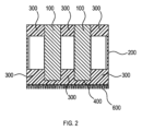
図2に示す更なる実施形態においては、冷却体400は、2つの部分にあり、第1の熱可塑性組成物から構成されるサブ領域と、第2の熱可塑性組成物から構成されるサブ領域とを有する。第1の熱可塑性組成物から構成されるサブ領域は、ホルダー300から遠い方の側面が平面であり、この平面側面は、第2の熱可塑性組成物600から構成される領域と物質間結合によって接合されている。
In a further embodiment shown in FIG. 2, the cooling
更なる実施形態において、筺体の材料は、該筺体の総重量に対して、前記第1の熱可塑性ポリマーを90重量%以上含む。ポリマーの配合に組み込まれている、又はすでに組み込まれているフィラー及び他のポリマー添加剤は、ポリマー(「ポリマー組成物」)のこの重量比に含まれる。この重量比は、筺体の総重量に対して、好ましくは95重量%以上、より好ましくは99重量%以上である。よって、筺体は「1成分型筺体」として特徴付けることができる。1つの材料のみを使用することで、製造工程を削減することができる。 In a further embodiment, the housing material comprises 90% or more by weight of the first thermoplastic polymer, based on the total weight of the housing. Fillers and other polymer additives that are or have been incorporated into the polymer formulation are included in this weight ratio of the polymer ("polymer composition"). This weight ratio is preferably 95% or more, more preferably 99% or more, based on the total weight of the housing. Thus, the housing can be characterized as a "one-component housing". The use of only one material can reduce manufacturing steps.
更なる実施形態において、筺体の材料は、前記第1の熱可塑性ポリマー組成物とは異なり、前記第1の熱可塑性ポリマー組成物が存在しない筺体の区域に存在する第2の熱可塑性ポリマー組成物を更に含む。第1のポリマー組成物に関して述べた事は、原則として、第2の熱可塑性ポリマー組成物にも当てはまる。第2の熱可塑性ポリマー組成物のポリマーは、第1の熱可塑性ポリマー組成物のポリマーと同じであるが、熱伝導性フィラーの量が少ないか、又は除去されていることが好ましい。このような「2成分型筺体」では、射出成形法で異なる流れ方をする熱可塑性物質を、良好な熱伝導率の重要性がより低い筺体上の場所で使用することによって、通常、製造要件を満たすことができる。第1の熱可塑性ポリマー組成物と、第2の熱可塑性ポリマー組成物とは、伴ってそれらの界面で物質間結合を形成する。 In a further embodiment, the material of the enclosure further comprises a second thermoplastic polymer composition different from the first thermoplastic polymer composition and present in areas of the enclosure where the first thermoplastic polymer composition is absent. What has been said with respect to the first polymer composition also applies in principle to the second thermoplastic polymer composition. The polymer of the second thermoplastic polymer composition is preferably the same as the polymer of the first thermoplastic polymer composition, but with a reduced amount of thermally conductive filler or without it. In such "two-component enclosures", manufacturing requirements can usually be met by using thermoplastics that flow differently in the injection molding process in places on the enclosure where good thermal conductivity is less important. The first thermoplastic polymer composition and the second thermoplastic polymer composition form inter-material bonds together at their interface.
更なる実施形態において、前記第2の熱可塑性ポリマー組成物のポリマーは、ポリカーボネート、ポリアミド、アクリロニトリル-ブタジエン-スチレンコポリマー、ポリフェニレンスルフィド、ポリプロピレン、又はこれらのポリマーのうち少なくとも2種の混合物の中から選択される。繰り返しを避けるために、第1のポリマー組成物に関して上で述べたことを参照することができる。 In a further embodiment, the polymer of the second thermoplastic polymer composition is selected from among polycarbonate, polyamide, acrylonitrile-butadiene-styrene copolymer, polyphenylene sulfide, polypropylene, or a mixture of at least two of these polymers. To avoid repetition, reference may be made to what has been said above with respect to the first polymer composition.
更なる実施形態において、前記第2の熱可塑性ポリマー組成物は難燃剤を含有する。好適な難燃剤は、特に、BDP(ビスフェノールAビス(ジフェニルホスフェート))等のホスフェートである。更に好適な難燃剤は、式(I)及び式(II)の環状ホスファゼン及び鎖状ホスファゼン等のホスファゼンである:

本発明に従って使用される式(I)の環状ホスファゼン中、式(I)中のaが3~8の範囲の整数、特に好ましくは3~5の範囲内の整数であるものを使用することが好ましい。 Among the cyclic phosphazenes of formula (I) used in accordance with the present invention, it is preferable to use those in which a in formula (I) is an integer in the range of 3 to 8, and particularly preferably an integer in the range of 3 to 5.
本発明に従って使用される式(II)の鎖状ホスファゼン中、bが3~1000の範囲、特に好ましくは3~100の範囲、特に好ましくは3~25の範囲の整数であるものを使用することが好ましい。 Among the linear phosphazenes of formula (II) used in accordance with the present invention, it is preferable to use those in which b is an integer in the range of 3 to 1000, particularly preferably in the range of 3 to 100, and particularly preferably in the range of 3 to 25.
例えば、日本の香川県の株式会社伏見製薬所から、Rabitle(商標)FP110(CAS番号1203646-63-2)の商品名で入手できるような環状フェノキシホスファゼンを使用することが特に好ましく、又は、aが3の場合であれば、2,2,4,4,6,6-ヘキサヒドロ-2,2,4,4,6,6-ヘキサフェノキシトリアザトリホスホリン(CAS番号1184-10-7)を使用することが特に好ましい。 For example, it is particularly preferred to use a cyclic phenoxyphosphazene such as that available from Fushimi Pharmaceutical Co., Ltd., Kagawa, Japan, under the trade name Rabitle™ FP110 (CAS No. 1203646-63-2), or, when a is 3, 2,2,4,4,6,6-hexahydro-2,2,4,4,6,6-hexaphenoxytriazatriphosphorine (CAS No. 1184-10-7).
Claims (10)
筺体壁(200)と、
前記筺体壁(200)に接合した、前記少なくとも1つの発熱素子(100)を収容するホルダー(300)と、
前記筺体壁(200)の側面に配置され、前記筺体壁(200)に接合した冷却体(400)と、
を備え、
ここで、前記ホルダー(300)が前記筺体の内部に配置される一方で、前記冷却体(400)が前記筺体の外側に配置され、
前記筺体壁(200)、前記ホルダー(300)、及び前記冷却体(400)が、一体的な部品として共に存在しており、ここで、前記冷却体(400)が、少なくとも1つの冷媒用流路(500)を有し、前記冷却体(400)の少なくともサブ領域が、ASTM E1461-01に従って求めた熱伝導率が0.2W/(m K)以上である第1の熱可塑性ポリマー組成物からなることを特徴とする、筺体。 An enclosure for at least one heating element (100), comprising:
An enclosure wall (200);
a holder (300) attached to the housing wall (200) and housing the at least one heating element (100);
A cooling body (400) disposed on a side surface of the housing wall (200) and joined to the housing wall (200);
Equipped with
Here, the holder (300) is disposed inside the housing, while the cooling body (400) is disposed outside the housing;
An enclosure, characterized in that the enclosure wall (200), the holder (300) and the cooling body (400) are present together as an integral part, the cooling body (400) having at least one flow channel (500) for a coolant, and at least a sub-area of the cooling body (400) consists of a first thermoplastic polymer composition having a thermal conductivity, determined according to ASTM E1461-01, of 0.2 W/(m K) or more.
Applications Claiming Priority (3)
| Application Number | Priority Date | Filing Date | Title |
|---|---|---|---|
| EP18208973.0 | 2018-11-28 | ||
| EP18208973 | 2018-11-28 | ||
| PCT/EP2019/081103 WO2020108988A1 (en) | 2018-11-28 | 2019-11-13 | Integrated cooling element for a battery module |
Publications (3)
| Publication Number | Publication Date |
|---|---|
| JP2022510621A JP2022510621A (en) | 2022-01-27 |
| JPWO2020108988A5 JPWO2020108988A5 (en) | 2022-11-22 |
| JP7635124B2 true JP7635124B2 (en) | 2025-02-25 |
Family
ID=64556815
Family Applications (1)
| Application Number | Title | Priority Date | Filing Date |
|---|---|---|---|
| JP2021529363A Active JP7635124B2 (en) | 2018-11-28 | 2019-11-13 | Integrated cooling element for battery modules |
Country Status (6)
| Country | Link |
|---|---|
| US (1) | US20210399358A1 (en) |
| EP (1) | EP3888158B1 (en) |
| JP (1) | JP7635124B2 (en) |
| KR (1) | KR20210093912A (en) |
| CN (1) | CN113196553B (en) |
| WO (1) | WO2020108988A1 (en) |
Families Citing this family (3)
| Publication number | Priority date | Publication date | Assignee | Title |
|---|---|---|---|---|
| KR20220053268A (en) * | 2020-10-22 | 2022-04-29 | 주식회사 엘지에너지솔루션 | Battery pack and manufacturing method thereof |
| DE102022102620A1 (en) | 2022-02-03 | 2023-08-03 | Webasto SE | Cell holder for holding a plurality of battery cells and vehicle battery assembly |
| DE102023113877A1 (en) * | 2023-05-26 | 2024-11-28 | Bayerische Motoren Werke Aktiengesellschaft | Housing for a battery, battery with the housing, method for producing the battery and motor vehicle |
Citations (5)
| Publication number | Priority date | Publication date | Assignee | Title |
|---|---|---|---|---|
| JP2002528619A (en) | 1998-11-03 | 2002-09-03 | ゼネラル・エレクトリック・カンパニイ | Polycarbonate sheet with improved flame retardancy |
| JP2008204990A (en) | 2007-02-16 | 2008-09-04 | Matsushita Electric Ind Co Ltd | Power storage unit |
| JP2010540715A (en) | 2007-09-26 | 2010-12-24 | ダウ グローバル テクノロジーズ インコーポレイティド | Improved carbonate polymer blend with reduced gloss |
| WO2014208423A1 (en) | 2013-06-26 | 2014-12-31 | 三菱瓦斯化学株式会社 | Flame retardant sheet or film, product using same, and method for manufacturing same |
| JP2018116805A (en) | 2017-01-17 | 2018-07-26 | 積水化学工業株式会社 | Secondary battery module |
Family Cites Families (12)
| Publication number | Priority date | Publication date | Assignee | Title |
|---|---|---|---|---|
| US6886625B1 (en) * | 2001-08-23 | 2005-05-03 | Cool Options, Inc. | Elastomeric heat sink with a pressure sensitive adhesive backing |
| US20070037053A1 (en) * | 2005-08-12 | 2007-02-15 | Satish Anantharaman | Battery case having improved thermal conductivity |
| JP4508221B2 (en) * | 2007-08-27 | 2010-07-21 | 豊田合成株式会社 | Battery assembly |
| DE102008024672A1 (en) * | 2008-05-21 | 2009-11-26 | Bayer Materialscience Ag | Low-temperature polycarbonate blends |
| DE102008031175A1 (en) * | 2008-07-03 | 2010-01-07 | Johnson Controls Hybrid And Recycling Gmbh | Rundzellenakkumulator |
| DE102008058351A1 (en) * | 2008-11-20 | 2010-06-02 | Kronos International, Inc. | Surface treated titanium dioxide pigments for plastics and method of manufacture |
| JP5833519B2 (en) * | 2012-09-27 | 2015-12-16 | アイシン軽金属株式会社 | Cell type battery case |
| EP3053206B1 (en) * | 2013-10-02 | 2017-08-02 | Covestro Deutschland AG | Battery module having a safety section, battery pack, and electric vehicle |
| DE102014201165A1 (en) | 2014-01-23 | 2015-08-06 | Robert Bosch Gmbh | Battery pack with air cooling |
| DE102014221684A1 (en) | 2014-07-11 | 2016-01-14 | Robert Bosch Gmbh | Housing for receiving a plurality of battery cells with a cooling device integrated in the housing |
| JP5955990B2 (en) * | 2014-08-27 | 2016-07-20 | 武延 本郷 | Planar heating device, snow melting device and lighting device |
| US10862078B2 (en) * | 2017-01-24 | 2020-12-08 | Ticona Llc | Battery module for an electric vehicle |
-
2019
- 2019-11-13 US US17/294,481 patent/US20210399358A1/en not_active Abandoned
- 2019-11-13 KR KR1020217015762A patent/KR20210093912A/en active Pending
- 2019-11-13 CN CN201980078090.7A patent/CN113196553B/en active Active
- 2019-11-13 EP EP19804700.3A patent/EP3888158B1/en active Active
- 2019-11-13 JP JP2021529363A patent/JP7635124B2/en active Active
- 2019-11-13 WO PCT/EP2019/081103 patent/WO2020108988A1/en not_active Ceased
Patent Citations (5)
| Publication number | Priority date | Publication date | Assignee | Title |
|---|---|---|---|---|
| JP2002528619A (en) | 1998-11-03 | 2002-09-03 | ゼネラル・エレクトリック・カンパニイ | Polycarbonate sheet with improved flame retardancy |
| JP2008204990A (en) | 2007-02-16 | 2008-09-04 | Matsushita Electric Ind Co Ltd | Power storage unit |
| JP2010540715A (en) | 2007-09-26 | 2010-12-24 | ダウ グローバル テクノロジーズ インコーポレイティド | Improved carbonate polymer blend with reduced gloss |
| WO2014208423A1 (en) | 2013-06-26 | 2014-12-31 | 三菱瓦斯化学株式会社 | Flame retardant sheet or film, product using same, and method for manufacturing same |
| JP2018116805A (en) | 2017-01-17 | 2018-07-26 | 積水化学工業株式会社 | Secondary battery module |
Also Published As
| Publication number | Publication date |
|---|---|
| CN113196553B (en) | 2024-11-29 |
| JP2022510621A (en) | 2022-01-27 |
| EP3888158A1 (en) | 2021-10-06 |
| US20210399358A1 (en) | 2021-12-23 |
| KR20210093912A (en) | 2021-07-28 |
| EP3888158B1 (en) | 2023-04-05 |
| CN113196553A (en) | 2021-07-30 |
| WO2020108988A1 (en) | 2020-06-04 |
Similar Documents
| Publication | Publication Date | Title |
|---|---|---|
| JP7635124B2 (en) | Integrated cooling element for battery modules | |
| CN104124488B (en) | Device for the battery module of indirect cooling environment protection type automobile | |
| US10862078B2 (en) | Battery module for an electric vehicle | |
| KR101470072B1 (en) | Heat control plate for battery cell module and battery cell module having the same | |
| KR102256098B1 (en) | Battery Pack having heat conductive medium of louver fin form | |
| JP5994345B2 (en) | Storage battery temperature control device | |
| US10847770B2 (en) | Battery module | |
| KR101780037B1 (en) | Cooling device for battery cell and battery module comprising the same | |
| JP5712697B2 (en) | Heat dissipation structure of heat dissipation member and heating element | |
| CN113614985B (en) | Battery module and battery pack including the same | |
| US20150034287A1 (en) | Heat exchanger for cooling a vehicle battery, in particular for hybrid or electric vehicles | |
| CN110326154B9 (en) | Battery module case and battery module including the same | |
| US20200122589A1 (en) | Battery for a motor vehicle, and motor vehicle | |
| KR20170014924A (en) | Battery Module of Indirect Cooling | |
| CN114051667B (en) | Battery module, battery pack including the battery module, and vehicle including the battery pack | |
| JP2007234371A (en) | Power supply device for vehicle | |
| WO2023204261A1 (en) | Battery holder, battery pack, and battery holder manufacturing method | |
| KR102825106B1 (en) | Curable composition | |
| KR101637765B1 (en) | Thermal control system of the battery module | |
| KR20130121255A (en) | Battery cooling device for vehicle | |
| CN119948674A (en) | Double-walled battery housing to provide heat transfer | |
| KR20170136066A (en) | Heat dissipation cartridge and battery pack for electric vehicle using the same | |
| WO2022265018A1 (en) | Case and pack |
Legal Events
| Date | Code | Title | Description |
|---|---|---|---|
| A521 | Request for written amendment filed |
Free format text: JAPANESE INTERMEDIATE CODE: A523 Effective date: 20221111 |
|
| A621 | Written request for application examination |
Free format text: JAPANESE INTERMEDIATE CODE: A621 Effective date: 20221111 |
|
| A977 | Report on retrieval |
Free format text: JAPANESE INTERMEDIATE CODE: A971007 Effective date: 20231226 |
|
| A131 | Notification of reasons for refusal |
Free format text: JAPANESE INTERMEDIATE CODE: A131 Effective date: 20240206 |
|
| A711 | Notification of change in applicant |
Free format text: JAPANESE INTERMEDIATE CODE: A712 Effective date: 20240401 |
|
| A521 | Request for written amendment filed |
Free format text: JAPANESE INTERMEDIATE CODE: A523 Effective date: 20240507 |
|
| A521 | Request for written amendment filed |
Free format text: JAPANESE INTERMEDIATE CODE: A523 Effective date: 20240925 |
|
| A131 | Notification of reasons for refusal |
Free format text: JAPANESE INTERMEDIATE CODE: A131 Effective date: 20241022 |
|
| A521 | Request for written amendment filed |
Free format text: JAPANESE INTERMEDIATE CODE: A523 Effective date: 20241211 |
|
| TRDD | Decision of grant or rejection written | ||
| A01 | Written decision to grant a patent or to grant a registration (utility model) |
Free format text: JAPANESE INTERMEDIATE CODE: A01 Effective date: 20250128 |
|
| A61 | First payment of annual fees (during grant procedure) |
Free format text: JAPANESE INTERMEDIATE CODE: A61 Effective date: 20250212 |
|
| R150 | Certificate of patent or registration of utility model |
Ref document number: 7635124 Country of ref document: JP Free format text: JAPANESE INTERMEDIATE CODE: R150 |