JP7630516B2 - Medical Device Connections - Google Patents
Medical Device Connections Download PDFInfo
- Publication number
- JP7630516B2 JP7630516B2 JP2022535565A JP2022535565A JP7630516B2 JP 7630516 B2 JP7630516 B2 JP 7630516B2 JP 2022535565 A JP2022535565 A JP 2022535565A JP 2022535565 A JP2022535565 A JP 2022535565A JP 7630516 B2 JP7630516 B2 JP 7630516B2
- Authority
- JP
- Japan
- Prior art keywords
- snap
- lock
- stent
- present disclosure
- medical device
- Prior art date
- Legal status (The legal status is an assumption and is not a legal conclusion. Google has not performed a legal analysis and makes no representation as to the accuracy of the status listed.)
- Active
Links
Images


Classifications
-
- A—HUMAN NECESSITIES
- A61—MEDICAL OR VETERINARY SCIENCE; HYGIENE
- A61F—FILTERS IMPLANTABLE INTO BLOOD VESSELS; PROSTHESES; DEVICES PROVIDING PATENCY TO, OR PREVENTING COLLAPSING OF, TUBULAR STRUCTURES OF THE BODY, e.g. STENTS; ORTHOPAEDIC, NURSING OR CONTRACEPTIVE DEVICES; FOMENTATION; TREATMENT OR PROTECTION OF EYES OR EARS; BANDAGES, DRESSINGS OR ABSORBENT PADS; FIRST-AID KITS
- A61F2/00—Filters implantable into blood vessels; Prostheses, i.e. artificial substitutes or replacements for parts of the body; Appliances for connecting them with the body; Devices providing patency to, or preventing collapsing of, tubular structures of the body, e.g. stents
- A61F2/02—Prostheses implantable into the body
- A61F2/24—Heart valves ; Vascular valves, e.g. venous valves; Heart implants, e.g. passive devices for improving the function of the native valve or the heart muscle; Transmyocardial revascularisation [TMR] devices; Valves implantable in the body
- A61F2/2427—Devices for manipulating or deploying heart valves during implantation
-
- A—HUMAN NECESSITIES
- A61—MEDICAL OR VETERINARY SCIENCE; HYGIENE
- A61F—FILTERS IMPLANTABLE INTO BLOOD VESSELS; PROSTHESES; DEVICES PROVIDING PATENCY TO, OR PREVENTING COLLAPSING OF, TUBULAR STRUCTURES OF THE BODY, e.g. STENTS; ORTHOPAEDIC, NURSING OR CONTRACEPTIVE DEVICES; FOMENTATION; TREATMENT OR PROTECTION OF EYES OR EARS; BANDAGES, DRESSINGS OR ABSORBENT PADS; FIRST-AID KITS
- A61F2/00—Filters implantable into blood vessels; Prostheses, i.e. artificial substitutes or replacements for parts of the body; Appliances for connecting them with the body; Devices providing patency to, or preventing collapsing of, tubular structures of the body, e.g. stents
- A61F2/02—Prostheses implantable into the body
- A61F2/24—Heart valves ; Vascular valves, e.g. venous valves; Heart implants, e.g. passive devices for improving the function of the native valve or the heart muscle; Transmyocardial revascularisation [TMR] devices; Valves implantable in the body
- A61F2/2412—Heart valves ; Vascular valves, e.g. venous valves; Heart implants, e.g. passive devices for improving the function of the native valve or the heart muscle; Transmyocardial revascularisation [TMR] devices; Valves implantable in the body with soft flexible valve members, e.g. tissue valves shaped like natural valves
- A61F2/2418—Scaffolds therefor, e.g. support stents
-
- A—HUMAN NECESSITIES
- A61—MEDICAL OR VETERINARY SCIENCE; HYGIENE
- A61F—FILTERS IMPLANTABLE INTO BLOOD VESSELS; PROSTHESES; DEVICES PROVIDING PATENCY TO, OR PREVENTING COLLAPSING OF, TUBULAR STRUCTURES OF THE BODY, e.g. STENTS; ORTHOPAEDIC, NURSING OR CONTRACEPTIVE DEVICES; FOMENTATION; TREATMENT OR PROTECTION OF EYES OR EARS; BANDAGES, DRESSINGS OR ABSORBENT PADS; FIRST-AID KITS
- A61F2/00—Filters implantable into blood vessels; Prostheses, i.e. artificial substitutes or replacements for parts of the body; Appliances for connecting them with the body; Devices providing patency to, or preventing collapsing of, tubular structures of the body, e.g. stents
- A61F2/82—Devices providing patency to, or preventing collapsing of, tubular structures of the body, e.g. stents
- A61F2/86—Stents in a form characterised by the wire-like elements; Stents in the form characterised by a net-like or mesh-like structure
- A61F2/90—Stents in a form characterised by the wire-like elements; Stents in the form characterised by a net-like or mesh-like structure characterised by a net-like or mesh-like structure
-
- A—HUMAN NECESSITIES
- A61—MEDICAL OR VETERINARY SCIENCE; HYGIENE
- A61F—FILTERS IMPLANTABLE INTO BLOOD VESSELS; PROSTHESES; DEVICES PROVIDING PATENCY TO, OR PREVENTING COLLAPSING OF, TUBULAR STRUCTURES OF THE BODY, e.g. STENTS; ORTHOPAEDIC, NURSING OR CONTRACEPTIVE DEVICES; FOMENTATION; TREATMENT OR PROTECTION OF EYES OR EARS; BANDAGES, DRESSINGS OR ABSORBENT PADS; FIRST-AID KITS
- A61F2/00—Filters implantable into blood vessels; Prostheses, i.e. artificial substitutes or replacements for parts of the body; Appliances for connecting them with the body; Devices providing patency to, or preventing collapsing of, tubular structures of the body, e.g. stents
- A61F2/82—Devices providing patency to, or preventing collapsing of, tubular structures of the body, e.g. stents
- A61F2002/828—Means for connecting a plurality of stents allowing flexibility of the whole structure
-
- A—HUMAN NECESSITIES
- A61—MEDICAL OR VETERINARY SCIENCE; HYGIENE
- A61F—FILTERS IMPLANTABLE INTO BLOOD VESSELS; PROSTHESES; DEVICES PROVIDING PATENCY TO, OR PREVENTING COLLAPSING OF, TUBULAR STRUCTURES OF THE BODY, e.g. STENTS; ORTHOPAEDIC, NURSING OR CONTRACEPTIVE DEVICES; FOMENTATION; TREATMENT OR PROTECTION OF EYES OR EARS; BANDAGES, DRESSINGS OR ABSORBENT PADS; FIRST-AID KITS
- A61F2/00—Filters implantable into blood vessels; Prostheses, i.e. artificial substitutes or replacements for parts of the body; Appliances for connecting them with the body; Devices providing patency to, or preventing collapsing of, tubular structures of the body, e.g. stents
- A61F2/95—Instruments specially adapted for placement or removal of stents or stent-grafts
- A61F2002/9505—Instruments specially adapted for placement or removal of stents or stent-grafts having retaining means other than an outer sleeve, e.g. male-female connector between stent and instrument
-
- A—HUMAN NECESSITIES
- A61—MEDICAL OR VETERINARY SCIENCE; HYGIENE
- A61F—FILTERS IMPLANTABLE INTO BLOOD VESSELS; PROSTHESES; DEVICES PROVIDING PATENCY TO, OR PREVENTING COLLAPSING OF, TUBULAR STRUCTURES OF THE BODY, e.g. STENTS; ORTHOPAEDIC, NURSING OR CONTRACEPTIVE DEVICES; FOMENTATION; TREATMENT OR PROTECTION OF EYES OR EARS; BANDAGES, DRESSINGS OR ABSORBENT PADS; FIRST-AID KITS
- A61F2220/00—Fixations or connections for prostheses classified in groups A61F2/00 - A61F2/26 or A61F2/82 or A61F9/00 or A61F11/00 or subgroups thereof
- A61F2220/0025—Connections or couplings between prosthetic parts, e.g. between modular parts; Connecting elements
- A61F2220/0033—Connections or couplings between prosthetic parts, e.g. between modular parts; Connecting elements made by longitudinally pushing a protrusion into a complementary-shaped recess, e.g. held by friction fit
-
- A—HUMAN NECESSITIES
- A61—MEDICAL OR VETERINARY SCIENCE; HYGIENE
- A61F—FILTERS IMPLANTABLE INTO BLOOD VESSELS; PROSTHESES; DEVICES PROVIDING PATENCY TO, OR PREVENTING COLLAPSING OF, TUBULAR STRUCTURES OF THE BODY, e.g. STENTS; ORTHOPAEDIC, NURSING OR CONTRACEPTIVE DEVICES; FOMENTATION; TREATMENT OR PROTECTION OF EYES OR EARS; BANDAGES, DRESSINGS OR ABSORBENT PADS; FIRST-AID KITS
- A61F2250/00—Special features of prostheses classified in groups A61F2/00 - A61F2/26 or A61F2/82 or A61F9/00 or A61F11/00 or subgroups thereof
- A61F2250/0058—Additional features; Implant or prostheses properties not otherwise provided for
- A61F2250/006—Additional features; Implant or prostheses properties not otherwise provided for modular
Landscapes
- Health & Medical Sciences (AREA)
- Cardiology (AREA)
- Engineering & Computer Science (AREA)
- Biomedical Technology (AREA)
- Heart & Thoracic Surgery (AREA)
- Transplantation (AREA)
- Oral & Maxillofacial Surgery (AREA)
- Vascular Medicine (AREA)
- Life Sciences & Earth Sciences (AREA)
- Animal Behavior & Ethology (AREA)
- General Health & Medical Sciences (AREA)
- Public Health (AREA)
- Veterinary Medicine (AREA)
- Prostheses (AREA)
- Infusion, Injection, And Reservoir Apparatuses (AREA)
Description
本発明は、新規の医療用の接続装置、少なくとも1つの新規の医療用の接続装置を備える医療装置ならびに医療用のプロテーゼへの新規の医療用の接続装置の使用に関する。 The present invention relates to a novel medical connection device, a medical device comprising at least one novel medical connection device, and the use of the novel medical connection device in a medical prosthesis.
低侵襲技術およびカテーテルベースの埋込み技術は長年にわたって進歩し、現在多くの医療分野で実現可能である。 Minimally invasive and catheter-based implantation techniques have advanced over the years and are now feasible in many medical fields.
多くの医療分野で、現在、カテーテルベースの技術によって患者を治療することが可能になり、患者の体調および手術に伴うリスクのために適切に治療することができなかった患者の治療が可能になった。このようなカテーテルベースの技術は、患者の体内へのそれぞれ異なるアクセス経路を介して医療装置を所望の標的部位に埋め込むための例えばカテーテルおよび/またはイントロデューサシースなどの送達システムに適用される。 In many medical fields, catheter-based technologies now make it possible to treat patients who could not be adequately treated due to their physical condition and the risks associated with surgery. Such catheter-based technologies apply to delivery systems, e.g., catheters and/or introducer sheaths, for implanting medical devices at desired target sites via different access routes into the patient's body.
このような処置では、使用されるプロテーゼは1つのパーツで構成されているか、2つ以上のパーツで構成されている。パーツは、互いに縫い合わせるか、2つのパーツを互いに形状接続することによって互いに取り付けることができる。展開処置中に生体内で異なるパーツを組み立てることも可能である。適正な形状接続および耐久性は、そのような医療装置の重要な側面である。 In such procedures, the prosthesis used may consist of one part or may consist of two or more parts. The parts may be attached to each other by sewing them together or by form-fitting two parts together. It is also possible to assemble the different parts in vivo during the deployment procedure. Proper form-fit and durability are important aspects of such medical devices.
特に、近年、心臓弁膜症および心臓弁の欠損の治療はますます成功するようになっている。例としては、大動脈弁治療または僧帽弁治療などの、心臓弁置換療法のための経心尖、経頸静脈および経大腿動脈の処置がある。 In particular, in recent years, the treatment of valvular heart disease and defects has become increasingly successful. Examples include transapical, transjugular and transfemoral procedures for heart valve replacement therapy, such as aortic or mitral valve repair.
多くの場合、組織ベースの置換弁を備えたステントベースのプロテーゼが使用され、カテーテル送達システムを使用して生来の心臓弁を置換するために埋め込まれる。 Often, a stent-based prosthesis with a tissue-based replacement valve is used and implanted to replace the native heart valve using a catheter delivery system.
交換用の心臓弁プロテーゼは、圧着してカテーテルに装着する必要がある。このようなプロテーゼは、単一のパーツで構成されてよく、または2つ以上のパーツで構成されてもよい。このようなプロテーゼの1つの態様は、患者への埋込み前または埋込み時に、1つの機能的なプロテーゼを形成するために、様々なパーツを接続することである。 The replacement heart valve prosthesis must be crimped and attached to a catheter. Such a prosthesis may be constructed of a single part, or may be constructed of two or more parts. One aspect of such a prosthesis is that the various parts are connected to form a functional prosthesis prior to or at the time of implantation in the patient.
より詳細には、医療装置に有用なかつ/またはカテーテルベースの送達方法に良好に適合する寸法を示す、使いやすくて信頼性の高い接続手段を提供すること、または、従来技術に対して改善された機構を備えた医療装置に有用な接続手段を提供することが課題である。 More specifically, the objective is to provide an easy to use and reliable connection means useful for medical devices and/or exhibiting dimensions that are well suited to catheter-based delivery methods, or to provide a connection means useful for medical devices with improved mechanisms over the prior art.
したがって、2つの医療装置パーツまたは多数の医療装置パーツを接続するために有用な、好ましくはカテーテルベースの送達方法の必要性に適合する、使いやすくて信頼性の高い接続手段が必要とされている。 Therefore, there is a need for an easy-to-use and reliable connection means useful for connecting two or multiple medical device parts, preferably adapted to the needs of catheter-based delivery methods.
したがって、本開示の1つの目的は、医療装置パーツを容易にかつ/または効率よくかつ/または高い信頼性でかつ/またはカテーテル圧着および/またはカテーテル送達に適合可能に組み合わせるための信頼性の高い接続手段を提供すること、または、少なくとも先行技術の欠点が実質的に回避されるか先行技術に対して減じられた欠点を示す接続手段を提供することである。 Accordingly, one object of the present disclosure is to provide a reliable connection means for easily and/or efficiently and/or reliably and/or compatiblely combining medical device parts for catheter crimping and/or catheter delivery, or at least to provide a connection means that substantially avoids or exhibits reduced disadvantages relative to the prior art.
開示の簡単な概要
1つの態様では、本開示は、2つ以上の医療装置パーツを接続するために有用な医療用の接続装置において、2つの医療装置パーツの2つの接続機構の係合および係止を含み、第1の接続機構は、第1の医療装置の一部を形成しており、第2の接続機構は、第2の医療装置の一部を形成しており、医療用の接続装置は、少なくとも1つのスナップ係止舌片と1つのスナップ係止カバーとを備えているか示していることを特徴とする、医療用の接続装置に関する。
BRIEF SUMMARY OF THE DISCLOSURE In one aspect, the present disclosure relates to a medical connection device useful for connecting two or more medical device parts, comprising engagement and locking of two connection mechanisms of two medical device parts, a first connection mechanism forming part of the first medical device and a second connection mechanism forming part of the second medical device, the medical connection device comprising or exhibiting at least one snap-lock tongue and one snap-lock cover.
別の態様では、本開示は、2パーツ医療装置であって、第1のパーツと、第2のパーツとを備え、各々のパーツは、少なくとも1つの接続機構を備え、第1のパーツの1つの接続機構と、第2のパーツの1つの接続機構とは、同一方向または反対方向で位置合わせされており、スナップ係止カバーが、2つの接続機構に係合しており、2つの接続機構は、少なくとも1つのスナップ係止舌片、好ましくは1つまたは2つのスナップ係止舌片と、各々の接続機構の少なくとも1つの支柱舌片ストップとによって係止され、複数の医療装置パーツは接続されてもよい、2パーツ医療装置に関する。 In another aspect, the present disclosure relates to a two-part medical device, comprising a first part and a second part, each part comprising at least one connection mechanism, the one connection mechanism of the first part and the one connection mechanism of the second part being aligned in the same or opposite directions, a snap-lock cover engaging the two connection mechanisms, the two connection mechanisms being locked by at least one snap-lock tongue, preferably one or two snap-lock tongues, and at least one strut tongue stop of each connection mechanism, and multiple medical device parts may be connected.
別の態様では、本開示は、2パーツステントであって、内側ステントと、外側ステントとを備え、各々のステントは、少なくとも1つの接続機構を備え、第1のステントの1つの接続機構と、第2のステントの1つの接続機構とは、同一方向または反対方向で位置合わせされており、スナップ係止カバーが、2つの接続機構に係合していて、少なくとも1つのスナップ係止舌片、好ましくは1つまたは2つのスナップ係止舌片と、各々の接続機構の少なくとも1の支柱舌片ストップとによって2つの接続機構を係止しており、複数の医療装置パーツは接続されてもよい、2パーツステントに関する。 In another aspect, the present disclosure relates to a two-part stent comprising an inner stent and an outer stent, each stent comprising at least one connection mechanism, the one connection mechanism of the first stent and the one connection mechanism of the second stent being aligned in the same or opposite direction, a snap-lock cover engaging the two connection mechanisms and locking the two connection mechanisms with at least one snap-lock tongue, preferably one or two snap-lock tongues, and at least one strut tongue stop of each connection mechanism, and multiple medical device parts may be connected to the two-part stent.
別の態様では、本開示は、心臓弁置換プロテーゼであって、置換弁と、2パーツステントとを備え、2パーツステントは、内側ステントと、外側ステントとを備え、各々のステントは、少なくとも1つの接続機構を備え、第1のステントの1つの接続機構と、第2のステントの1つの接続機構とは、同一方向または反対方向で位置合わせされており、スナップ係止カバーが、2つの接続機構に係合していて、少なくとも1つのスナップ係止舌片と、各々の接続機構の1つの支柱舌片ストップとによって2つの接続機構を係止している、心臓弁置換プロテーゼに関する。 In another aspect, the present disclosure relates to a heart valve replacement prosthesis comprising a replacement valve and a two-part stent, the two-part stent comprising an inner stent and an outer stent, each stent comprising at least one connection mechanism, the one connection mechanism of the first stent and the one connection mechanism of the second stent being aligned in the same or opposite directions, and a snap-lock cover engaging the two connection mechanisms and locking the two connection mechanisms with at least one snap-lock tongue and one strut tongue stop of each connection mechanism.
別の態様では、本開示は、組み立てられた医療装置のプロテーゼを得るために、本開示による1つ以上の医療用の接続装置を使用して、2つ以上の医療装置パーツ、例えばステントパーツを組み立てるための方法に関する。 In another aspect, the present disclosure relates to a method for assembling two or more medical device parts, such as stent parts, using one or more medical connecting devices according to the present disclosure to obtain an assembled medical device prosthesis.
別の態様では、本開示は、それぞれ異なる医療装置パーツを接続するための、本開示による1つ以上の医療用の接続装置の使用に関する。 In another aspect, the present disclosure relates to the use of one or more medical connection devices according to the present disclosure to connect different medical device parts.
本開示の様々な実施形態は、以下の図によって例示される。
詳細な説明
以下に本開示の特定の用語を定義する。本開示の文脈におけるそれ以外の技術用語は、該当する当業者であれば理解することができる。
DETAILED DESCRIPTION Certain terms of the present disclosure are defined below. Other technical terms in the context of the present disclosure will be understood by those of ordinary skill in the relevant art.
本開示の意味での「プロテーゼ」または「医療装置」または「インプラント」という用語は、低侵襲性であるか、またはカテーテルベースの処置によって送達することができる任意の医療装置として理解される。これらの用語は交換可能に使用することができる。本開示の意味でのプロテーゼは、例えば、ステント、またはステントベースのプロテーゼ、または大動脈弁の置換心臓弁、僧帽弁の置換心臓弁もしくは三尖弁の置換心臓弁のようなステントベースの置換心臓弁プロテーゼであってよい。 The term "prosthesis" or "medical device" or "implant" in the sense of this disclosure is understood as any medical device that is minimally invasive or can be delivered by a catheter-based procedure. These terms can be used interchangeably. A prosthesis in the sense of this disclosure can be, for example, a stent, or a stent-based prosthesis, or a stent-based replacement heart valve prosthesis, such as a replacement heart valve for the aortic valve, a replacement heart valve for the mitral valve, or a replacement heart valve for the tricuspid valve.
本開示の意味での「カテーテル」または「送達装置」という用語は、例えば、生来の大動脈弁、僧帽弁または三尖弁のような心臓弁を置換するために、決定された部位で患者にプロテーゼを展開するために使用される装置として理解される。 The term "catheter" or "delivery device" in the sense of this disclosure is understood as a device used to deploy a prosthesis in a patient at a determined site, for example to replace a heart valve such as the native aortic, mitral or tricuspid valve.
本開示の意味での「メッシュステント」または「編込みメッシュステント」または「編込みステント」は、例えば、レーザ切断されたニチノール管とは対照的に、ワイヤで構成されるステントである。 A "mesh stent" or "woven mesh stent" or "woven stent" within the meaning of this disclosure is a stent that is constructed of wire, as opposed to, for example, laser cut Nitinol tubing.
本開示の意味での「切断ステント」または「レーザ切断ステント」は、例えばニチノール管からレーザ切断されたステントである。ニチノール管が出発点であるため、外側の半径は内側の半径よりも大きく、ひいてはステントに切断されると、ステントは、(当初の管の)外側から内側に向かうテーパ状である。 A "cut stent" or "laser cut stent" within the meaning of this disclosure is a stent that has been laser cut, for example, from a Nitinol tube. Since the Nitinol tube is the starting point, the outside radius is larger than the inside radius, and thus, when cut into a stent, the stent tapers from the outside (of the original tube) to the inside.
本開示の意味での「ステント領域」または「複数のステント領域」は、外側ステント、メッシュステントもしくは置換心臓弁プロテーゼの規定された領域であり、特にそれは、近位領域、中間領域もしくは遠位領域、または心房、弁輪もしくは心室として規定された長手方向セクションもしくは外側セクションである。 A "stent region" or "stent regions" in the sense of this disclosure is a defined region of an outer stent, mesh stent or replacement heart valve prosthesis, in particular a proximal region, an intermediate region or a distal region, or a longitudinal section or an outer section defined as an atrium, annulus or ventricle.
本開示の意味での「近位領域」、「中間領域」、「遠位領域」は、カテーテルの使用によって埋込みを行う手術者に関連するステントもしくはプロテーゼの領域を示し、近位が手術者に近く、遠位が手術者から離れている。「中間領域」は、本開示の意味でのステントもしくはプロテーゼにおいて、遠位領域と近位領域との間の領域を意味している。個人(人または患者)の原位置、すなわち、生体内での本来の血流に関して、「近位領域」はまた、流入端部または流入領域を表すことができ、「遠位領域」はまた、流出端部または流出領域を示すことができる。近位は心房、中間は弁輪、遠位は心室と示すこともできる。 The terms "proximal region", "intermediate region" and "distal region" in the sense of this disclosure refer to the region of the stent or prosthesis relative to the operator who performs the implantation by use of a catheter, with proximal being closer to the operator and distal being further from the operator. "Intermediate region" refers to the region of the stent or prosthesis in the sense of this disclosure between the distal region and the proximal region. With respect to the native blood flow in situ, i.e. in vivo, of an individual (person or patient), the "proximal region" can also refer to the inflow end or inflow region and the "distal region" can also refer to the outflow end or outflow region. Proximal can also be referred to as the atrium, intermediate as the annulus and distal as the ventricle.
本開示の意味での「弁輪領域(annulus area)」または「弁輪領域(annular area)」は、内生の心臓弁の各々の領域、または埋込み部位に位置決めされて内生の弁輪と位置合わせされることになっている置換心臓弁またはステントの各々の領域を規定する。 "Annulus area" or "annular area" within the meaning of this disclosure defines the respective area of an endogenous heart valve or the respective area of a replacement heart valve or stent that is positioned at the implantation site and is to be aligned with the endogenous annulus.
本開示の意味での「弁輪下領域」は、内生の心臓弁の弁輪の遠位方向(または流入方向または心室方向)にあるプロテーゼの領域である。プロテーゼは、「弁輪下領域」をU字形もしくはV字形の溝領域、および遠位領域で覆ってよい。 The "subannular region" in the sense of this disclosure is the region of the prosthesis that is distal (or in the inflow or ventricular direction) of the annulus of the endogenous heart valve. The prosthesis may cover the "subannular region" with a U-shaped or V-shaped groove region, and a distal region.
本開示の意味での「溝」は、他の領域よりも小さい直径を示すステントの領域またはプロテーゼの領域を表し、前記溝の遠位および近位で、より大きな直径を有するステントの他の領域またはプロテーゼの他の領域が前記溝の近辺にある。前記溝は、V字形もしくはU字形またはそれらの組み合わせ、または他の任意の曲げられた有用な幾何学的形状を有することができ、または、溝は、心房のステント領域および心室のステント領域と比較してわずかに小さい直径によって特徴付けることができる。 A "groove" in the sense of this disclosure refers to a region of a stent or a region of a prosthesis exhibiting a smaller diameter than other regions, distal and proximal to said groove, and adjacent to said groove other regions of the stent or prosthesis having a larger diameter. The grooves may have a V-shape or U-shape or a combination thereof, or any other useful curved geometric shape, or the grooves may be characterized by a slightly smaller diameter compared to the atrial and ventricular stented regions.
本開示の意味での「マルチパーツステント」は、「2パーツステント」または「3パーツステント」を指すことができ、内側ステントは、本開示による医療用の接続装置によって接続される。本開示による医療用の接続装置は、内側ステントの心房端部もしくは心房領域、または生来の弁の弁輪領域に位置決めすることができる。 A "multi-part stent" in the sense of this disclosure can refer to a "two-part stent" or a "three-part stent" in which the inner stent is connected by a medical connection device according to the present disclosure. The medical connection device according to the present disclosure can be positioned at the atrial end or atrial region of the inner stent or in the annular region of the native valve.
本開示の意味での「標的部位」は、置換心臓弁プロテーゼが埋め込まれる位置または場所であり、ここで機能障害または機能不全が、例えば、三尖弁の弁輪または僧帽弁の弁輪において、治療される。 A "target site" within the meaning of this disclosure is the location or place where a replacement heart valve prosthesis is implanted where a dysfunction or insufficiency is to be treated, for example, in the tricuspid or mitral annulus.
本開示の意味でのステントの「接続」は、2つの医療装置パーツを本開示による1つの医療用の接続装置で固定する方法であり、幾つかの医療装置パーツは、この方法により、すでに埋込みの準備がされ、または、患者への埋込み中に組み立てられる最終的な複数パーツの医療装置に組み立てられ得る。 A "connection" of a stent in the sense of this disclosure is a method of fastening two medical device parts with one medical connecting device according to this disclosure, and several medical device parts may be assembled in this manner into a final multi-part medical device that is either already prepared for implantation or assembled during implantation in a patient.
本開示の意味での「固定手段」または「アンカ固定手段」は、内側ステントに接続され、任意選択で付加的な手段と協働して、実質的に標的部位にプロテーゼをアンカ固定するための構成要素である。特定の態様では、固定手段は、アンカ固定ループと、アンカ固定アームと、接続アーチと、内側ステントアンカとから構成されるか、それらを備え、好ましくは、接続手段は、固定手段の内側ステントアンカを内側ステントに接続する。 "Fixing means" or "anchor fixing means" in the sense of this disclosure is a component connected to the inner stent and, optionally in cooperation with additional means, for substantially anchoring the prosthesis at the target site. In a particular embodiment, the fixing means consists of or comprises an anchor fixing loop, an anchor fixing arm, a connecting arch, and an inner stent anchor, and preferably a connecting means connects the inner stent anchor of the fixing means to the inner stent.
本開示の意味での「アンカ固定ループ」は、ステントもしくはプロテーゼの固定に有用なステントの一部であり、標的部位でのステントもしくはプロテーゼの移動を回避するのを補助する。概して、本開示の意味でのアンカ固定ループは、ステントもしくはプロテーゼの改善された固定に有用な手段であり、ループは、内側ステントに固定されるか、内側ステントに接続されるか、内側ステントの一部を形成するか、内側ステントの一体部分である。本開示の意味での「ループ」または「複数のループ」は、丸みを帯びた形、正方形などの異なる形状を有してよく、規定のパターンで規定された領域に配置される。本開示の意味での「ループ」は、ステントの内側表面に関して規定された角度を示し、ステントもしくはプロテーゼが展開初期に、場合によっては部分的な展開後にカテーテルに回収される際に、直線状に延びても反転してもよいように設計されてよい。 An "anchor loop" in the sense of the present disclosure is a part of a stent that is useful for the fixation of a stent or prosthesis and helps to avoid migration of the stent or prosthesis at the target site. In general, an anchor loop in the sense of the present disclosure is a means useful for improved fixation of a stent or prosthesis, where the loop is fixed to, connected to, forms part of, or is an integral part of the inner stent. A "loop" or "loops" in the sense of the present disclosure may have different shapes, such as rounded, square, etc., and are arranged in a defined pattern and in a defined area. A "loop" in the sense of the present disclosure presents a defined angle with respect to the inner surface of the stent and may be designed to extend straight or to invert when the stent or prosthesis is retrieved into the catheter during initial deployment and, in some cases, after partial deployment.
本開示の意味での「角度構造」または「角度」は、内側ステントのような他のステント構造に関して、特定の幾何学的形状を規定するために特定の領域またはステント層に引かれる、前記ステントパーツまたはアーチまたは層の2つの補助線の間の角度である。 An "angular structure" or "angle" in the sense of this disclosure is the angle between two auxiliary lines of said stent parts or arches or layers that are drawn in a particular region or stent layer to define a particular geometric shape with respect to other stent structures, such as an inner stent.
本開示の意味での「半径方向の力」は、半径方向の外向き方向に、ステントもしくはプロテーゼによって示される力であり、より具体的には、メッシュステントまたは例えばニチノールステントなどのレーザ切断ステントであってもよいプロテーゼの外側ステントによって発揮される力である。半径方向の力は、特定のメッシュステントまたは切断ステントの設計に依存し、材料密度、例えばメッシュステントの単位面積あたりのワイヤの密度、または特定のレーザ切断ステントのレベルもしくは領域の、例えば、近位/心房、中間/弁輪もしくは遠位/心室の領域の周方向のセルの数と前記セルのサイズとに関連する。本開示による置換心臓弁プロテーゼにおける半径方向の力は、外側ステントに対して、または内側ステントおよび外側ステントと固定手段との組み合わせに対して、周辺組織との良好な接触を提供し、ステントもしくはプロテーゼの固定機能を支持する大きさで、また任意選択で、標的部位の内生の環境および生体への干渉を避けるためにできるだけ小さい大きさで選択することになる。したがって、埋込み部位および内生の組織および機能との干渉を回避するために、それは大きさで選択される。半径方向の力は、他の手段、例えば固定用のループによって、その固定機能のために支持されてよい。 A "radial force" in the sense of the present disclosure is a force exhibited by a stent or prosthesis in a radially outward direction, more specifically by the outer stent of the prosthesis, which may be a mesh stent or a laser cut stent, such as a Nitinol stent. The radial force depends on the design of the particular mesh or cut stent and is related to the material density, e.g. the density of wires per unit area of a mesh stent, or the number of circumferential cells and the size of said cells at the level or area of a particular laser cut stent, e.g. the proximal/atrial, middle/annular or distal/ventricular area. The radial force in a replacement heart valve prosthesis according to the present disclosure will be selected for the outer stent, or for the combination of the inner and outer stents with the fixation means, in a magnitude that provides good contact with the surrounding tissue and supports the fixation function of the stent or prosthesis, and optionally as small as possible to avoid interference with the endogenous environment and organism of the target site. It is therefore selected in a magnitude to avoid interference with the implantation site and endogenous tissues and functions. The radial force may be supported by other means, such as a fastening loop, for its fastening function.
本開示の意味での「標的領域」は、例えば三尖弁または僧帽弁であってよい生来の心臓弁のような生来の器官を取り囲むかまたはその中にある三次元空間である。 A "target area" within the meaning of this disclosure is the three-dimensional space surrounding or within a native organ, such as a native heart valve, which may be, for example, the tricuspid or mitral valve.
本開示の意味でのループの「非外傷性設計」とは、ステントもしくはプロテーゼのループまたは他の手段またはパーツが、前記パーツまたは少なくともそれらが接触する組織の損傷または/および負傷を最小限に抑えるように製造されたパーツに接触する周辺組織もしくは組織のあらゆる損傷もしくは実質的にあらゆる損傷を避けるように設計されていることである。 An "atraumatic design" of a loop in the sense of this disclosure means that the loop or other means or parts of a stent or prosthesis are designed to avoid any or substantially any damage to surrounding tissue or tissues contacting said parts or at least parts manufactured to minimize damage or/and injury to the tissues they contact.
本開示の意味での、例えば、外側メッシュステント内の内側のレーザ切断ステント、またはレーザ切断外側ステント内のレーザ切断内側ステントを備える、ステントもしくは置換心臓弁プロテーゼの「適合性」は、標的組織との正の干渉に関する。「適合性」は、ステントもしくはプロテーゼの埋込み部位への良好な幾何学的形状適応を示し、ステントもしくはプロテーゼが有利な固定特性、弁機能に関する良好な機能性を示し、同時に内生の心臓構造および心臓機能への干渉を最小限に抑える設計に関する。 In the sense of the present disclosure, the "fit" of a stent or replacement heart valve prosthesis, for example with an inner laser-cut stent within an outer mesh stent or a laser-cut inner stent within a laser-cut outer stent, refers to a positive interference with the target tissue. "Fit" refers to a design that exhibits good geometrical adaptation of the stent or prosthesis to the implantation site, that exhibits favorable fixation properties, good functionality with respect to valve function, and at the same time minimizes interference with endogenous cardiac structures and functions.
本開示の意味での「医療装置」は、医療の文脈または医療用途で使用することができる任意のパーツもしくはパーツのアセンブリを意味してよい。それは、カテーテルのような送達システムを使用する低侵襲性技術による外科手術による患者への送達物の埋込みのために設計された手術装置または微小侵襲性ツールまたは医療装置に関連してよい。特に、「医療装置」は、ステント、置換心臓弁プロテーゼ、修復装置、または一般的な置換装置、例えば、大動脈弁、肺動脈弁、僧帽弁、三尖弁などの置換心臓弁プロテーゼに関連してよい。 A "medical device" in the sense of the present disclosure may refer to any part or assembly of parts that can be used in a medical context or application. It may relate to a surgical device or a micro-invasive tool or a medical device designed for implantation into a patient by surgery with minimally invasive techniques using a delivery system such as a catheter. In particular, a "medical device" may relate to a stent, a replacement heart valve prosthesis, a repair device, or a general replacement device, e.g., a replacement heart valve prosthesis such as aortic valve, pulmonary valve, mitral valve, tricuspid valve, etc.
本開示の意味での「医療用の接続装置」とは、最小では、2つの接続手段(例えば支柱)と、2つの接続手段を解離可能にまたは解離不能に接続する手段を備えるカバー、例えばスナップ係止カバーとを用いて、医療装置の2つのパーツを接続することができる装置を意味している。本開示による医療用の接続装置を使用することにより、複数の医療装置パーツを接続して、患者にすぐに使用することができる最終的な医療装置を形成することができ、または、その全部もしくは一部を、例えばカテーテルによって、送達処置中に接続することができる。したがって、本開示による1つ、2つ、3つ、4つ、5つ、6つ、またはそれ以上の医療用の接続装置は、パーツが別々に製造され、後にこの方法により接続される複数パーツの医療装置を提供するために有用であってよい。 A "medical connection device" in the sense of this disclosure means, at a minimum, a device that can connect two parts of a medical device using two connection means (e.g., posts) and a cover, e.g., a snap-lock cover, that has a means for releasably or non-releasably connecting the two connection means. Using a medical connection device according to the present disclosure, multiple medical device parts can be connected to form a final medical device that is ready for use on a patient, or all or part of it can be connected during a delivery procedure, e.g., by a catheter. Thus, one, two, three, four, five, six or more medical connection devices according to the present disclosure may be useful to provide a multi-part medical device, the parts of which are manufactured separately and later connected by this method.
本開示の意味での「スナップ係止カバー」とは、ステントもしくは置換心臓弁プロテーゼの、支柱などの2つの接続手段を解離可能にまたは解離不能に接続することができるパーツを意味している。それは、1つ以上のスナップ係止舌片と、1つ以上のスナップ係止ハードストップと、1つ以上のスナップ係止カバースカートとを備えてよい。 "Snap-lock cover" in the sense of this disclosure means a part that can releasably or non-releasably connect two connection means, such as struts, of a stent or replacement heart valve prosthesis. It may comprise one or more snap-lock tongues, one or more snap-lock hard stops, and one or more snap-lock cover skirts.
本開示の意味での「スナップ係止舌片」は、支柱などの接続手段に係合し、例えば2つの支柱を所定の位置に保持し、ひいては2つの医療用パーツを接続するために有用なスナップ係止カバーの一部を形成するパーツを意味している。スナップ係止舌片は各支柱に対応部分を有しており、ひいては2つの支柱を共に保持して固定することができる。 "Snap-lock tongue" in the sense of this disclosure means a part that engages with a connecting means such as a post and holds, for example, two posts in place, thus forming part of a snap-lock cover useful for connecting two medical parts. The snap-lock tongue has a corresponding portion on each post, thus holding and fixing the two posts together.
本開示の意味での「スナップ係止ハードストップ」は、支柱に係合するためのスナップ係止カバー内の事前に規定されたストップを意味している。 "Snap-lock hard stops" within the meaning of this disclosure means predefined stops in the snap-lock cover for engaging the posts.
本開示の意味での「支柱舌片ストップ」は、スナップ係止舌片と係合して接続部を形成し、それぞれ2つの医療用パーツとその接続手段とを互いに接続することができるストラットまたは任意の接続手段に構成された対応部分である。 A "strut tongue stop" in the sense of this disclosure is a corresponding part configured on a strut or any connecting means that can engage with a snap-lock tongue to form a connection, connecting two medical parts and their connecting means, respectively, to each other.
本開示の意味での「接続機構」は、スナップ係止カバーに係合することを意図された医療装置パーツの一部である。 A "connection mechanism" in the sense of this disclosure is a portion of a medical device part that is intended to engage with a snap-lock cover.
本開示の意味での「スナップ係止カバースカート」は、例えば2つの支柱の位置合わせをサポートし、スナップ係止カバー内の接続手段の接続および適正な位置決めを付加するために有用なスナップ係止カバーの一部である。 A "snap-lock cover skirt" in the sense of this disclosure is a part of a snap-lock cover that is useful, for example, to support the alignment of two posts and to add connection and proper positioning of a connection means within the snap-lock cover.
本開示の意味での「遠位」とは、カテーテル手段を使用するときに手術者から離れていることを意味している。 "Distal" in the sense of this disclosure means away from the operator when using the catheter means.
本開示の意味での「近位」とは、カテーテル手段を使用するときに手術者に近いことを意味している。 "Proximal" in the sense of this disclosure means closer to the operator when using the catheter means.
本開示の意味での「長手」または「長手方向」とは、医療装置、例えば心臓弁置換プロテーゼの長手方向を意味している。 "Longitudinal" or "longitudinal" in the sense of this disclosure means the longitudinal direction of a medical device, e.g., a heart valve replacement prosthesis.
本開示の意味での「所定の角度を成して内向き」とは、例えば、弁もしくは置換心臓弁において、外側パーツもしくは外側領域に対して装置の中間パーツまたは内側パーツもしくは内側領域に向かう方向を意味している。 "At an angle inward" in the sense of this disclosure means, for example, in a valve or replacement heart valve, in a direction toward an intermediate part or inner part or region of a device relative to an outer part or region.
本開示の意味での「丸みを帯びた形状」、「正方形に切断した形状」または「角形状」は、スナップ係止カバーの設計に関する。正方形に切断した形状または角形状は、使用する空間が少なく、ひいては医療装置がカテーテル送達によって埋め込まれ、置換心臓弁プロテーゼのように装置を圧着する必要がある状況では、小さいことが好ましい可能性がある。 "Rounded", "square cut" or "angular" in the sense of this disclosure refers to the design of the snap lock cover. Square cut or angular shapes use less space and thus may be preferable in situations where the medical device is implanted by catheter delivery and the device needs to be crimped, such as a replacement heart valve prosthesis.
本開示の意味での「位置」または「位置決め」という用語は、概して、本開示によって接続される2つの医療装置パーツのより広い配向に関連する。用語はまた、送達装置もしくは展開装置を操作している手術者に関して、近位(手術者/カテーテルのハンドルに近い)および遠位(手術者/カテーテルのハンドルから離れている)の意味で空間内の配向を指すことができる。心臓弁置換プロテーゼの文脈において、それは、カテーテル処置によって生来の心臓弁部位に埋め込まれるプロテーゼの長手方向に延びる形状を指す。 The term "position" or "positioning" in the sense of this disclosure generally relates to the broader orientation of two medical device parts that are connected by this disclosure. The term can also refer to orientation in space in a proximal (closer to the operator/catheter handle) and distal (away from the operator/catheter handle) sense with respect to the operator manipulating the delivery or deployment device. In the context of a heart valve replacement prosthesis, it refers to the longitudinal shape of the prosthesis that is implanted at the native heart valve site by catheterization.
本開示の意味でのパーツを「位置合わせする」またはパーツの「位置合わせ」とは、2つの接続手段を相並んで微少位置合わせすること、およびスナップ係止カバーに適合するように2つの接続手段を微少位置合わせすることを意味している。したがって、スナップ係止カバーおよびそれとの接続の状況において、2つの医療装置パーツの支柱の配向は、極めて近接した距離にある。好ましくは、2つの支柱(接続手段)の位置合わせは、スナップ係止カバーとの接続前または接続中に2つの支柱を極めて正確に位置合わせするために、支柱位置合わせ手段によって支持することができる。 "Aligning" parts or "aligning" parts in the sense of this disclosure means micro-aligning two connection means side by side and micro-aligning two connection means to fit the snap lock cover. Thus, in the context of the snap lock cover and its connection, the orientation of the posts of the two medical device parts is in very close distance. Preferably, the alignment of the two posts (connection means) can be supported by a post alignment means to align the two posts very accurately before or during connection with the snap lock cover.
支柱とスナップ係止カバーとの位置合わせは、医療装置パーツが、切断された当初の管(レーザ切断方法)に関連して、または手術者に対してカテーテルの送達処置中および展開処置中に空間内に位置決めされる配向、すなわち(カテーテルのハンドルに対して)手術者の近位、または(カテーテルのハンドルに対して)手術者の遠位に関連して、説明することが可能である。 The alignment of the posts and the snap lock cover can be described in terms of the original tube that was cut (laser cutting methods) or in terms of the orientation that the medical device parts are positioned in space relative to the operator during the catheter delivery and deployment procedures, i.e., proximal to the operator (relative to the catheter handle) or distal to the operator (relative to the catheter handle).
本開示の意味で「上から下に」もしくは「下から上に」(2つの用語は観察者の視点に関連する)または「重畳されて」位置合わせするとは、図2で説明するように、2つの接続手段を互いに位置決めすることを意味している。支柱(接続手段)は、図2に示すように、プロテーゼの近位方向から遠位方向に関連して重畳される。 In the sense of this disclosure, alignment "top-to-bottom" or "bottom-to-top" (the two terms relate to the viewer's point of view) or "overlapping" refers to positioning two connection means relative to one another as illustrated in FIG. 2. The posts (connection means) are overlapping relative to the proximal to distal direction of the prosthesis as shown in FIG. 2.
本開示の意味での内側パーツまたは内側ステントの接続機構の「管の切断縁部と管の切断縁部」を位置合わせすることは、当該の医療用パーツの製造方法およびレーザ切断方法にも言及する。この場合、管(例えばニチノール管)は、管の内側表面および外側表面と、管が切断された縁部とを有している。医療用パーツ、例えばステントが切断される当初の管に言及すると、管ひいては医療用パーツ(例えばステント)の内側および外側での本開示による位置合わせを規定することができ、他方では、切断レベルおよび切断面または切断面積とを規定することができる。したがって、2つのパーツの外側と内側の位置合わせを規定することができ、視点に応じて、これは、内側と外側(inside-to-outside)もしくは外側と内側(outside-to-inside)(これは、異なる視点のため、同一のことが異なることを意味している)または外側と外側(outside-to-outside)もしくは内側と内側(inside-to-inside)を意味することができ、相並んでとは、切断側と切断側(cut side-to-cut side)を意味するができる。 Aligning the "cut edge of the tube to the cut edge of the tube" of the connection mechanism of the inner part or inner stent in the sense of the present disclosure also refers to the manufacturing method and laser cutting method of the medical part in question. In this case, the tube (e.g. Nitinol tube) has an inner and outer surface of the tube and an edge at which the tube is cut. With reference to the original tube from which the medical part, e.g. stent, is cut, the alignment according to the present disclosure on the inside and outside of the tube and thus the medical part (e.g. stent) can be defined, on the other hand, the cut level and the cut surface or cut area can be defined. Thus, the alignment of the outside and the inside of the two parts can be defined, and depending on the point of view, this can mean inside-to-outside or outside-to-inside (which means the same thing differently due to different points of view) or outside-to-outside or inside-to-inside, and side by side can mean cut side-to-cut side.
医療装置パーツの配向を規定する別の方法は、カテーテルを使用する手術者に関連してよく、すなわち、それぞれ、手術者とカテーテルのハンドルとに関連して、近位および遠位であってよい。 Another way to define the orientation of a medical device part may be relative to the operator using the catheter, i.e., proximal and distal relative to the operator and the handle of the catheter, respectively.
本開示の意味での、内側パーツもしくはステントの、接続機構を「相並んで」位置合わせすることは、2パーツステント(または2パーツ心臓弁置換プロテーゼ)の2つの支柱が、カテーテルベースの送達処置の場合に手術者の視点を基準として近位方向から遠位方向としても表現することができる、装置の長手方向と関連して相並んで位置決めされることを意味している。したがって、プロテーゼの支柱は、近位方向から遠位方向に関連して、また手術者に関連して、同一のレベルにある。 Aligning the connection mechanisms of the inner parts or stents "side-by-side" in the sense of this disclosure means that the two struts of a two-part stent (or two-part heart valve replacement prosthesis) are positioned side-by-side in relation to the longitudinal direction of the device, which in the case of a catheter-based delivery procedure can also be expressed as proximal to distal relative to the operator's point of view. Thus, the struts of the prosthesis are at the same level in relation to the proximal to distal direction and in relation to the operator.
本開示の意味での「内向きに向いた」方向とは、スナップ係止舌片のようなパーツが、その最外縁部を長手方向に100%向けるのではなく、装置(003)の長手方向に対して内向き方向に特定の角度を付けることを意味している。角度は有用なように変化してよく、ひいては5°~75°の間の角度を有してよい。 An "inwardly facing" orientation in the sense of this disclosure means that a part such as a snap-lock tongue does not have its outermost edge facing 100% in the longitudinal direction, but is angled inwardly relative to the longitudinal direction of the device (003). The angle may be usefully varied, and may thus have an angle between 5° and 75°.
本開示の意味での「係合する」または「係合」とは、2つの医療装置パーツを接続するために、接続および/または係止するための2つの手段が密接に接触することを意味している。 "Engage" or "engagement" in the sense of this disclosure means intimate contact of two means for connecting and/or locking to connect two medical device parts.
本開示の意味での「係止する」または「係止」とは、2つの医療装置パーツが、スナップ係止カバーと係合するように設計された機構によって接続されていることを意味している。 "Lock" or "locking" in the sense of this disclosure means that two medical device parts are connected by a mechanism designed to engage with a snap-lock cover.
本開示の意味での「スナップ係止カバー」とは、2つの医療装置パーツの2つの手段を機能的に接続し、それらの接続を安定かつ確実に容易にすることができるパーツを意味している。 A "snap-lock cover" in the sense of this disclosure means a part that functionally connects two means of two medical device parts and can facilitate their connection in a stable and reliable manner.
本開示の意味での「スナップ係止カバースカート」とは、スナップ係止カバーを延ばすことによって両側に安定性を付加するという意味で、確実な係止をサポートする機構を意味している。さらに、支柱ハードストップと組み合わせたスナップ係止カバースカートは、スナップ係止カバー内の支柱の傾き、ひいては支柱とスナップ係止カバーとの望ましくない分離を有利に低減するか、または実質的に完全に回避する。 "Snap-lock cover skirt" in the sense of this disclosure means a mechanism that supports positive locking in the sense that it adds stability to both sides by extending the snap-lock cover. Furthermore, the snap-lock cover skirt in combination with the post hard stop advantageously reduces or substantially completely avoids tilting of the post within the snap-lock cover and thus undesirable separation of the post and the snap-lock cover.
本開示の意味での「支柱位置合わせ手段」とは、図11に示されるように、2つの医療装置パーツの2つの接続手段(例えば、支柱)の位置合わせを容易にするために役立つ。支柱位置合わせ手段は、支柱を適正に組み立ててスナップ係止カバーに適正に位置決めし、係止することを有利に提供するだけでなく、支柱が互いにスライドすることを回避し、ひいては腐食または/および材料疲労を回避する。これは、支柱を相並んで位置合わせする一実施形態、および心臓の鼓動中に患者内で極めて高い力が発生する心臓弁置換プロテーゼの状況において極めて有利である可能性がある。 A "post alignment means" in the sense of this disclosure serves to facilitate alignment of two connection means (e.g., posts) of two medical device parts, as shown in FIG. 11. The post alignment means advantageously not only provides for proper assembly and proper positioning and locking of the posts into the snap-lock cover, but also prevents the posts from sliding against each other, thus avoiding corrosion or/and material fatigue. This can be extremely advantageous in an embodiment where the posts are aligned side-by-side, and in the context of heart valve replacement prostheses, where extremely high forces are generated within the patient during heart beating.
本開示の意味での「機構の対を接続する2つの支柱位置合わせ手段」または「機構の対を接続する」とは、対が、本開示による医療用の接続装置によって2つの医療装置パーツを接続するために使用されるパーツおよび対応部分であることを意味している。これにより、装置の位置合わせと耐久性とが向上する。 "Two post alignment means connecting a pair of features" or "connecting a pair of features" in the sense of this disclosure means that the pair are parts and counterparts used to connect two medical device parts by a medical connecting device according to this disclosure. This improves the alignment and durability of the device.
本開示の意味での「2パーツ」または「2パーツ医療装置」とは、各々の場合において、本開示による1つの医療用の接続装置で2つのパーツが接続されることを意味し、複数パーツ(2つ、3つ、4つ、5つ、6つまたはそれ以上)同士を接続して機能的な複数パーツの医療装置を形成することができる。 "Two-part" or "two-part medical device" within the meaning of this disclosure means, in each case, two parts connected by a single medical connection device according to this disclosure, and multiple parts (2, 3, 4, 5, 6 or more) can be connected together to form a functional multi-part medical device.
以下に、本開示の様々な態様を説明する。 Various aspects of this disclosure are described below.
本開示の1つの態様では、本願の根底にある課題は、2つ以上の医療装置パーツを接続するために有用な医療用の接続装置において、2つの医療装置パーツの2つの接続機構の係合および係止を含み、第1の接続機構が、第1の医療装置の一部を形成しており、第2の接続機構が、第2の医療装置の一部を形成しており、医療用の接続装置は、少なくとも1つのスナップ係止舌片と1つのスナップ係止カバーとを備えているかまたは示していることを特徴とする、医療用の接続装置によって解決される。 In one aspect of the present disclosure, the problem underlying the present application is solved by a medical connection device useful for connecting two or more medical device parts, the medical connection device comprising engagement and locking of two connection mechanisms of two medical device parts, the first connection mechanism forming part of the first medical device and the second connection mechanism forming part of the second medical device, the medical connection device comprising or exhibiting at least one snap-lock tongue and one snap-lock cover.
医療用の接続装置は、有利には、医療装置の2つ以上のパーツを接続するための高速で容易なかつ信頼性の高い手段を提供する。加えて、埋込み前もしくは埋込み中または送達プロセス中もしくは展開処置中に前記医療装置パーツを接続することが可能であってもよい。 Medical connection devices advantageously provide a fast, easy and reliable means for connecting two or more parts of a medical device. In addition, it may be possible to connect the medical device parts before or during implantation or during the delivery process or deployment procedure.
それぞれ異なる医療装置パーツは接続されさえすればよく、それぞれ異なるパーツの正確で緊密な接続を自動的に形成する。この接続は、その構造により、周辺組織の損傷を回避するスナップ係止カバーの非侵襲的で有利な形状のため、組織に損傷を与ない信頼性の高い安全な接続でもある。 The different medical device parts only need to be connected and automatically form a precise and tight connection between the different parts. This connection is also a reliable and safe connection without causing any damage to the tissue due to the non-invasive and advantageous shape of the snap-lock cover which avoids damage to the surrounding tissue due to its construction.
さらに、付加的な利点は、接続が、溶接、縫合または接着などの付加的な組立てステップまたは材料を含まないことである。 Furthermore, an added advantage is that the connection does not involve additional assembly steps or materials, such as welding, stitching or gluing.
加えて、本開示による有利な医療用の接続装置によって、医療用パーツの材料およびその材料は、患者への使用時に装置の材料および耐久性にマイナスの影響を与える可能性のある機械的応力、熱的応力、化学的応力または別の応力に曝されない。 In addition, the advantageous medical connection devices of the present disclosure do not expose the medical part materials and their materials to mechanical, thermal, chemical or other stresses that may negatively affect the materials and durability of the device during use on a patient.
最後に、本開示による有利な医療用の接続装置は、より高速な製造および組立て、低減された材料およびプロセス時間、ひいては、より少ないコストを伴う。したがって、本開示による医療用の接続装置は経済的に有利である。 Finally, the advantageous medical connection device according to the present disclosure involves faster manufacturing and assembly, reduced material and process time, and therefore less cost. Thus, the medical connection device according to the present disclosure is economically advantageous.
本開示による医療用の接続装置の使用はまた、化学的接続アプローチの既知の機構では不可能である特別な音によって再開される。 The use of the medical connection device according to the present disclosure is also reinstated by a special sound that is not possible with the known mechanisms of chemical connection approaches.
本開示による医療用の接続装置は、その設計の変形例を示すことができ、例えば、ステント、置換心臓弁プロテーゼに使用される特定の用途に適合させることができる。 The medical connection devices of the present disclosure may exhibit variations in their design and may be adapted for specific applications, such as for use with stents, replacement heart valve prostheses, etc.
特定の態様では、本開示による医療用の接続装置は、スナップ係止カバーが、少なくとも1つ、好ましくは2つ、3つ、4つ、5つ、6つ、7つまたは8つのスナップ係止ハードストップおよび/または少なくとも1つ、好ましくは2つ、3つまたは4つのスナップ係止カバースカートをさらに備えるように変更されていると好適であり得る。したがって、有利には、接続支柱の位置をより正確に調整することができ、2つ以上の異なる医療装置パーツを必要に応じて極めて正確に位置合わせして接続することができる。 In certain aspects, the medical connection device according to the present disclosure may be advantageously modified so that the snap-lock cover further comprises at least one, preferably two, three, four, five, six, seven or eight snap-lock hard stops and/or at least one, preferably two, three or four snap-lock cover skirts. Thus, advantageously, the position of the connection posts can be more precisely adjusted, and two or more different medical device parts can be connected with highly accurate alignment as required.
本開示による医療用の接続装置の1つ以上のスナップ係止ハードストップは、有用であって、他の設計上の特徴と調和するように位置決めすることができる。本開示による医療用の接続装置は、1つ以上のスナップ係止ハードストップが、スナップ係止カバーの近位端部もしくは遠位端部または/および遠位端部と近位端部との間の領域に位置決めされているように設計することができる。 The one or more snap-lock hard stops of the medical connection device according to the present disclosure can be positioned to be useful and consistent with other design features. The medical connection device according to the present disclosure can be designed such that the one or more snap-lock hard stops are positioned at the proximal or distal end of the snap-lock cover or/and in the area between the distal and proximal ends.
本開示による医療用の接続装置のスナップ係止カバーは、その幾何学的な寸法もしくは幾何学的な設計に限定されず、他の機構の必要性に応じて、機能的考慮および技術的考慮の下で適合させることができる。本開示によるスナップ係止カバーは、例えば、医療用の接続装置であってよく、スナップ係止カバーは、丸みを帯びた形状、正方形に切断された形状もしくは角形状または/および長手方向に延びる形状である。 The snap-lock cover of the medical connection device according to the present disclosure is not limited in its geometric dimensions or geometric design, and can be adapted under functional and technical considerations according to the needs of other mechanisms. The snap-lock cover according to the present disclosure can be, for example, a medical connection device, and the snap-lock cover is rounded, square-cut or angular, or/and longitudinally extending.
本開示の別の態様では、本願の根底にある課題は、2パーツ医療装置であって、第1のパーツと、第2のパーツとを備え、各々のパーツは、少なくとも1つの接続機構を備え、第1のパーツの1つの接続機構と、第2のパーツの1つの接続機構とは、同一方向または反対方向で位置合わせされており、スナップ係止カバーが、2つの接続機構に係合しており、2つの接続機構は、少なくとも1つのスナップ係止舌片、好ましくは1つまたは2つのスナップ係止舌片と、各々の接続機構の少なくとも1つの支柱舌片ストップとによって係止され、複数の医療装置パーツは接続されてもよい、2パーツ医療装置によって解決される。 In another aspect of the present disclosure, the problem underlying the present application is solved by a two-part medical device, comprising a first part and a second part, each part comprising at least one connecting mechanism, the one connecting mechanism of the first part and the one connecting mechanism of the second part being aligned in the same or opposite direction, a snap-lock cover engaging the two connecting mechanisms, the two connecting mechanisms being locked by at least one snap-lock tongue, preferably one or two snap-lock tongues, and at least one strut tongue stop of each connecting mechanism, and multiple medical device parts may be connected.
本開示の別の態様では、本願の根底にある課題は、2パーツステントであって、内側ステントと、外側ステントとを備え、各々のステントは、少なくとも1つの接続機構を備え、第1のステントの1つの接続機構と、第2のステントの1つの接続機構とは、同一方向または反対方向で位置合わせされており、スナップ係止カバーが、2つの接続機構に係合していて、少なくとも1つのスナップ係止舌片、好ましくは1つまたは2つのスナップ係止舌片と、各々の接続機構の少なくとも1つの支柱舌片ストップとによって2つの接続機構を係止しており、複数の医療装置パーツは接続されてもよい、2パーツステントによって解決される。 In another aspect of the present disclosure, the problem underlying the present application is solved by a two-part stent, comprising an inner stent and an outer stent, each stent comprising at least one connection mechanism, one connection mechanism of the first stent and one connection mechanism of the second stent being aligned in the same or opposite direction, a snap-lock cover engaging the two connection mechanisms and locking the two connection mechanisms by at least one snap-lock tongue, preferably one or two snap-lock tongues, and at least one strut tongue stop of each connection mechanism, and multiple medical device parts may be connected.
本開示の別の態様では、本願の根底にある課題は、心臓弁置換プロテーゼであって、置換弁と、2パーツステントとを備え、2パーツステントは、内側ステントと、外側ステントとを備え、各々のステントは、少なくとも1つの接続機構を備え、第1のステントの1つの接続機構と、第2のステントの1つの接続機構とは、同一方向または反対方向で位置合わせされており、スナップ係止カバーが、2つの接続機構に係合していて、少なくとも1つのスナップ係止舌片と、各々の接続機構の1つの支柱舌片ストップとによって2つの接続機構を係止している、心臓弁置換プロテーゼによって解決される。スナップ係止舌片および各々の支柱舌片ストップ、支柱ハードストップ、スナップ係止ハードストップの数は、各々の用途に有用であるように適合させることができ、各々の手段について1つ、2つ、3つ、4つ、5つまたは6つであってよい。 In another aspect of the present disclosure, the problem underlying the present application is solved by a heart valve replacement prosthesis comprising a replacement valve and a two-part stent, the two-part stent comprising an inner stent and an outer stent, each stent comprising at least one connection mechanism, the one connection mechanism of the first stent and the one connection mechanism of the second stent being aligned in the same or opposite direction, and a snap-lock cover engaging the two connection mechanisms and locking the two connection mechanisms by at least one snap-lock tongue and one strut tongue stop of each connection mechanism. The number of snap-lock tongues and each strut tongue stop, strut hard stop, snap-lock hard stop can be adapted to be useful for each application and may be one, two, three, four, five or six for each means.
(管を出発点とするため)当初の管に関して外側方向から内側方向へテーパ状になる管の切断縁部が、相並んだ領域の改善された位置合わせのために、テーパが反対方向に配向されるように位置合わせされるように、支柱が位置合わせされると有利であり得る。これは、心臓が鼓動しているときに、心臓弁が心臓にある状況での動作中に、より少ない腐食および摩耗を意味する場合がある。 It may be advantageous for the struts to be aligned so that the cut edges of the tube that taper from an outside direction to an inside direction with respect to the original tube (to start with the tube) are aligned so that the tapers are oriented in opposite directions for improved alignment of the side-by-side regions. This may mean less erosion and wear during operation in the context of the heart valve in the heart when the heart is beating.
本開示による、および上記のような心臓弁置換プロテーゼは、その材料が、患者に使用される際に、装置の材料および耐久性に悪影響を及ぼす可能性のある機械的、熱的、化学的または他の応力を受けないという利点を意味している。特に患者の心臓への埋込みの状況では、大きな力が発生し、優れた耐久性が必要となる。 Heart valve replacement prostheses according to the present disclosure and as described above have the advantage that their materials are not subject to mechanical, thermal, chemical or other stresses that may adversely affect the material and durability of the device when used in a patient. Especially in the context of implantation in a patient's heart, large forces are generated and excellent durability is required.
概して、以下の特徴の変形例は、2パーツまたは複数パーツで構成することができる2パーツ医療装置または2パーツステントまたは心臓弁置換プロテーゼに等しく適用される。 In general, the following feature variations apply equally to two-part medical devices or two-part stents or heart valve replacement prostheses, which may be constructed of two or more parts.
本開示による2パーツ医療装置または2パーツステントまたは心臓弁置換プロテーゼの一実施形態では、内側パーツもしくは内側ステントの接続機構は、内側パーツもしくは内側ステントの長手方向に対して約3°~60°、好ましくは5°~30°、より好ましくは25°の角度を成して内向きに向けられていることが有利であり得る。 In one embodiment of a two-part medical device or two-part stent or heart valve replacement prosthesis according to the present disclosure, the connection mechanism of the inner part or stent may advantageously be oriented inwardly at an angle of about 3° to 60°, preferably 5° to 30°, more preferably 25°, relative to the longitudinal direction of the inner part or stent.
接続されるパーツは、スナップ係止カバーによって2つのパーツを接続するための特別な支柱または他の手段を有することができ、パーツは、スナップ係止カバーによって接続され、それによって固定されるために適している。したがって、2つのパーツは、適正に位置合わせされ、信頼性が高いように接続されて、所望の最終的な医療装置を形成する。例えば2つのパーツは、最終的な医療装置を形成するために相互内に位置決めすることができる。好ましい実施形態では、本開示による2パーツ医療装置または2パーツステントまたは心臓弁置換プロテーゼは、有利に設計することができ、外側パーツもしくは外側ステントの接続機構は、遠位方向から近位方向に対して重畳されている(上から下に位置合わせされている)か、またはパーツまたはステントが切断された当初の管を基準にして、内側と外側、内側と内側もしくは外側と外側で相並んで位置合わせされているか、もしくは管の切断縁部と管の切断縁部で内側のパーツもしくは内側ステントの接続機構に位置合わせされている。 The parts to be connected may have special posts or other means for connecting the two parts by a snap-lock cover, and the parts are suitable for being connected by and fixed by the snap-lock cover. Thus, the two parts are properly aligned and reliably connected to form the desired final medical device. For example, the two parts may be positioned within each other to form the final medical device. In a preferred embodiment, a two-part medical device or two-part stent or heart valve replacement prosthesis according to the present disclosure may be advantageously designed such that the connection mechanism of the outer part or stent is superimposed (aligned from top to bottom) in the distal to proximal direction, or aligned side by side, inside to outside, inside to inside or outside to outside, relative to the original tube from which the parts or stents were cut, or aligned with the connection mechanism of the inner part or stent at the cut edge of the tube to the cut edge of the tube.
したがって、医療装置の単一パーツの設計または/およびこれらのパーツの互いの相対的な位置関係に応じて、接続手段、例えば2つの支柱(1つの医療装置パーツからの各支柱もしくは接続手段)は、組み立てられた医療装置の最終的な設計に最も良好に形状接続するように互いに位置決めされ、位置合わせされてよい。 Thus, depending on the design of the single parts of the medical device and/or the relative positioning of these parts to each other, the connection means, e.g., two posts (each post or connection means from one medical device part) may be positioned and aligned with each other to best form-fit the final design of the assembled medical device.
本開示によれば、医療用の接続装置の特定のパーツおよび手段または/および2パーツ医療装置または2パーツステントまたは心臓弁置換プロテーゼは、技術的利点または/および必要性に応じて変形させることができる。したがって、単一の特徴であるスナップ係止カバー、スナップ係止舌片、スナップ係止ハードストップ、支柱ハードストップ、支柱舌片ストップ、支柱位置合わせ手段、スナップ係止カバースカートおよび/または支柱(接続支柱または接続手段)は、特定の用途の下で要求されるように、それぞれ異なる設計、それぞれ異なる数を有することができる。本開示による医療用の接続装置または/および2パーツ医療装置または2パーツステントまたは心臓弁置換プロテーゼは、好ましくは、1つのスナップ係止カバーと、2つ、3つまたは4つのスナップ係止舌片と、接続機構の、対応する個数の支柱舌片ストップとを備えてよい。 According to the present disclosure, the specific parts and means of the medical connection device or/and the two-part medical device or the two-part stent or heart valve replacement prosthesis can be modified according to technical advantages or/and needs. Thus, the single features of the snap-lock cover, the snap-lock tongue, the snap-lock hard stop, the strut hard stop, the strut tongue stop, the strut alignment means, the snap-lock cover skirt and/or the strut (connecting strut or connecting means) can have different designs and different numbers as required under a specific application. The medical connection device or/and the two-part medical device or the two-part stent or heart valve replacement prosthesis according to the present disclosure may preferably comprise one snap-lock cover, two, three or four snap-lock tongues and a corresponding number of strut tongue stops of the connection mechanism.
本開示による別の好ましい実施形態では、2パーツ医療装置または2パーツステントまたは心臓弁置換プロテーゼは、1つのスナップ係止ハードストップと、各々の接続機構の1つの支柱ハードストップとを備えてもよく、2つ、3つまたは4つのスナップ係止ハードストップと、各々の接続機構の1つまたは2つの支柱ハードストップとを備えてもよい。 In another preferred embodiment according to the present disclosure, a two-part medical device or two-part stent or heart valve replacement prosthesis may have one snap-lock hard stop and one strut hard stop on each connection mechanism, or may have two, three or four snap-lock hard stops and one or two strut hard stops on each connection mechanism.
本開示による別の好ましい実施形態では、2パーツ医療装置または2パーツステントまたは心臓弁置換プロテーゼは、スナップ係止舌片が、医療装置、ステントもしくはプロテーゼの長手方向に位置決めされるか、長手方向に対して実質的に90°の角度を成して位置決めされるか、長手方向に対して5°~90°、もしくは10°~45°、もしくは45°の角度を成して位置決めされることを特徴としている。 In another preferred embodiment according to the present disclosure, the two-part medical device or two-part stent or heart valve replacement prosthesis is characterized in that the snap-lock tabs are positioned along the length of the medical device, stent or prosthesis, positioned at an angle of substantially 90° to the length, or positioned at an angle of 5° to 90°, or 10° to 45°, or 45° to the length.
本開示による別の好ましい実施形態では、2パーツ医療装置または2パーツステントまたは心臓弁置換プロテーゼは、接続機構が、医療装置、ステントまたはプロテーゼの各々のパーツから延在する支柱の遠位領域または遠位端部に位置決めされていることを特徴とする。 In another preferred embodiment according to the present disclosure, the two-part medical device or two-part stent or heart valve replacement prosthesis is characterized in that the connection mechanism is positioned at a distal region or distal end of a strut extending from each part of the medical device, stent or prosthesis.
本開示による別の好ましい実施形態では、2パーツ医療装置または2パーツステントまたは心臓弁置換プロテーゼは、接続機構または各々の接続機構が、少なくとも1つの支柱位置合わせ手段、好ましくは、接続機構の対の2つの支柱位置合わせ手段を備えることを特徴とする。 In another preferred embodiment according to the present disclosure, the two-part medical device or two-part stent or heart valve replacement prosthesis is characterized in that the or each connecting mechanism comprises at least one strut alignment means, preferably two strut alignment means of the pair of connecting mechanisms.
本開示による別の好ましい実施形態では、2パーツ医療装置または2パーツステントまたは心臓弁置換プロテーゼは、本開示による少なくとも1つの医療用の接続装置を備えることを特徴とする。 In another preferred embodiment according to the present disclosure, a two-part medical device or a two-part stent or heart valve replacement prosthesis is characterized in that it comprises at least one medical connection device according to the present disclosure.
本開示の別の態様では、本願の根底にある課題は、組み立てられた医療装置のプロテーゼを得るために、本開示による1つ以上の医療用の接続装置を使用して、2つ以上の医療装置パーツ、例えばステントパーツを組み立てるための方法によって解決される。 In another aspect of the present disclosure, the problem underlying the present application is solved by a method for assembling two or more medical device parts, e.g., stent parts, using one or more medical connecting devices according to the present disclosure to obtain an assembled medical device prosthesis.
特に、本開示による医療用の接続装置の組立ておよび医療用パーツを組み立てるための各々の方法は、接続が、溶接、縫合または接着などの時間および/または材料を要する付加的な組立てステップを伴わないという利点を有する。 In particular, the assembly of medical connection devices and respective methods for assembling medical parts according to the present disclosure have the advantage that the connections do not involve additional assembly steps that require time and/or material, such as welding, suturing or gluing.
本開示の別の態様では、本願の根底にある課題は、それぞれ異なる医療装置パーツを接続するために、本開示による1つ以上の医療用の接続装置を使用することによって解決される。 In another aspect of the present disclosure, the problem underlying the present application is solved by using one or more medical connecting devices according to the present disclosure to connect different medical device parts.
本開示による医療用の接続装置の使用は、従来技術の既知のアプローチに対して、容易で信頼性が高く、費用対効果の高いアプローチを提供し、ひいては、既知のアプローチに比べて優れている。 The use of the medical connection device according to the present disclosure provides an easy, reliable, and cost-effective approach to, and is therefore superior to, known approaches in the prior art.
実施例
以下の実施例は、本開示の様々な実施形態を説明するために役立つ。これらの例は、決して限定的なものとして解釈されることを意図したものではない。
EXAMPLES The following examples serve to illustrate various embodiments of the present disclosure and are not intended to be construed as limiting in any way.
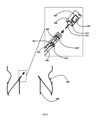
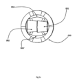
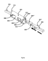
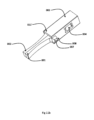
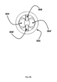
図1は、本開示による接続装置の一実施形態を示し、第1の支柱(001)および第2の支柱(002)は、スナップ係止カバー(003)の内側に配置され、第1の支柱(001)および第2の支柱(002)は、スナップ係止舌片(004)によって係止される。オプション機構のスナップ係止ハードストップ(008)および支柱ハードストップ(007,007’)は、スナップ係止カバー(003)内に支柱(001,002)をより適切に位置決めして係止するために有利であり得る。オプション機構のスナップ係止カバースカート(011,011’)は、スナップ係止カバー(003)内での支柱(001,002)の保持性をさらに向上させることができる。スナップ係止ハードストップ(008)および支柱ハードストップ(007,007’)は、支柱(001,002)がスナップ係止カバー(003)内でスライドし続けることを回避または防止することができる。スナップ係止カバースカート(011,011’)は、支柱(001,002)のねじれを回避または少なくとも軽減することをサポートし、ひいては支柱の係止解除を防止する。 1 shows an embodiment of a connection device according to the present disclosure, in which a first post (001) and a second post (002) are disposed inside a snap-lock cover (003), and the first post (001) and the second post (002) are locked by a snap-lock tongue (004). Optional features of the snap-lock hard stop (008) and post hard stop (007, 007') can be advantageous to better position and lock the posts (001, 002) in the snap-lock cover (003). Optional features of the snap-lock cover skirt (011, 011') can further improve the retention of the posts (001, 002) in the snap-lock cover (003). The snap-lock hard stop (008) and the post hard stop (007, 007') can prevent or prevent the post (001, 002) from continuing to slide within the snap-lock cover (003). The snap-lock cover skirt (011, 011') helps to prevent or at least reduce twisting of the post (001, 002), thus preventing the post from unlocking.
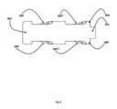
図2は、2パーツ心臓弁置換プロテーゼの縦断面を示す主要図であり、まだ組み立てられていないが、スナップ係止カバー(003)によって接続される予定のプロテーゼの異なるパーツからの支柱(001,002)の拡大図である。外側の第1のステント(005)と内側の第2のステント(006)とが図示されており、拡大図では、各々の支柱(001,002)が位置合わせされ(矢印参照)、次のステップでスナップ係止カバー(003)内に導入される様子が図示されている。第2のステント(006)は第1のステント(005)の内側に上向きに押圧され、ひいては支柱(001,002)は下と上に、または上と下に位置決めされる(第2のステント006の支柱002は「下の支柱」、第1のステント005の支柱001は「上の支柱」である)。また、それは、長手方向のステント/プロテーゼの方向と、埋込みおよび展開のためにカテーテル装置を操作する手術者との関係とで示すことができ、すなわち、遠位は「下方向」ひいては「下の支柱」であり、近位は「上方向」ひいては「上の支柱」である。位置合わせの際に、スナップ係止カバー(003)は、2つの支柱(001,002)に被せられ、スナップ係止舌片(004)によって係止され、オプション機構のスナップ係止ハードストップ(008)は、スナップ係止舌片(004)による支柱(001,002)の最適な係止のために、支柱ハードストップ(007,007’)によって2つの支柱(001,002)を適正な位置で停止させる。オプション機構のスナップ係止カバースカート(011,011’)は、近位方向および遠位方向(上方向および下方向)の付加的な係止力に寄与する。さらに、これらは、接続の開放を回避するかまたは防止することに寄与し、ひいては支柱の安全な接続に寄与することができる。
2 is a main view of a longitudinal section of a two-part heart valve replacement prosthesis, with a close-up of the struts (001, 002) from different parts of the prosthesis that are not yet assembled but are to be connected by a snap-lock cover (003). The outer first stent (005) and the inner second stent (006) are shown, and in the close-up the struts (001, 002) are shown aligned (see arrows) and introduced in the next step into the snap-lock cover (003). The second stent (006) is pressed upwards inside the first stent (005), thus the struts (001, 002) are positioned below and above or above and below (strut 002 of the
図2aは、図2の組立てプロセス(係止プロセス)の続きを示している。これで、2つのステント(005,006)の支柱(001,002)が完全に位置合わせされる。2つの支柱(001,002)が位置合わせされ、スナップ係止カバー(003)がそれらに被せられ、支柱(001,002)がスナップ係止カバー(003)の内側に導入される。 Figure 2a shows the continuation of the assembly process (locking process) of Figure 2. Now the struts (001, 002) of the two stents (005, 006) are perfectly aligned. Once the two struts (001, 002) are aligned, the snap-lock cover (003) is placed over them and the struts (001, 002) are introduced inside the snap-lock cover (003).
図2bは、接続されたステント(005,006)を拡大図で示しており、支柱(001,002)はスナップ係止カバー(003)の内側に導入されて、スナップ係止舌片(004)によって係止されている。適正かつ安全で確実な係止のための他のすべてのオプションの手段は、適正な位置(007,007’,008,011,011’)にある。 Figure 2b shows the connected stent (005, 006) in an enlarged view, with the struts (001, 002) introduced inside the snap-lock cover (003) and locked by the snap-lock tongues (004). All other optional means for proper, safe and secure locking are in the correct position (007, 007', 008, 011, 011').
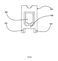
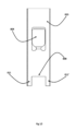
図3、図3a、図3bは、本開示によるスナップ係止カバーの異なる図(側面図および平面図)を示しており、スナップ係止カバー(003)は、2つのスナップ係止舌片(004,004’)と、2つのスナップ係止ハードストップ(008,008’)とを備える。 Figures 3, 3a and 3b show different views (side and top views) of a snap lock cover according to the present disclosure, where the snap lock cover (003) has two snap lock tongues (004, 004') and two snap lock hard stops (008, 008').
図3cは、スナップ係止カバー(003)の長手方向の切断面を示し、切断線(A-A)を示している。スナップ係止舌片(004,004’)は、内向きに向けられており、支柱(001,002、ここでは図示せず)がスナップ係止カバーの内側に必要なだけ導入されて押圧され、支柱(001,002)上の対応部分がスナップ係止舌片(004,004’)に係止されるような範囲まで可撓性である。オプション機構のスナップ係止ハードストップ(008,008’)およびスナップ係止カバースカート(011)もまた示されている。 Figure 3c shows a longitudinal cut of the snap-lock cover (003), showing the cut line (A-A). The snap-lock tongues (004, 004') are directed inward and are flexible to the extent that the posts (001, 002, not shown here) are introduced and pressed as far as necessary into the inside of the snap-lock cover, so that the corresponding parts on the posts (001, 002) are locked onto the snap-lock tongues (004, 004'). Optional features of the snap-lock hard stops (008, 008') and the snap-lock cover skirt (011) are also shown.
図4は、1つのスナップ係止舌片(004)のみが使用される本開示によるスナップ係止カバー(003)の変形例を示す。この図は、平面図と、切断面(B-B)と、オプション機構(008,008’,011)とを示している。 Figure 4 shows a variation of the snap-lock cover (003) according to the present disclosure in which only one snap-lock tab (004) is used. This figure shows a top view, a cutaway (B-B), and optional features (008, 008', 011).
図5は、2つの支柱(001,002)の位置合わせ(矢印を参照)の詳細を示し、支柱(001,002)の支柱舌片ストップ(009,009’)と支柱ハードストップ(007,007’、オプションである)とが示されている。 Figure 5 shows the alignment (see arrows) of the two posts (001, 002) in detail, showing the post tongue stops (009, 009') and post hard stops (007, 007', optional) of the posts (001, 002).
図5a、図5bは、2つの医療装置パーツを安全かつ簡単に接続するためのパーツ(001,002,003)の組立てを示している。図5aの矢印は、スナップ係止カバー(003)を支柱(001,002)に被せることを示している。図5bでは、パーツ(001,002,003)が組み立てられ、2つの医療用パーツが安全に相互に接続されている。 Figures 5a and 5b show the assembly of parts (001, 002, 003) to safely and easily connect two medical device parts. The arrow in Figure 5a shows the snap lock cover (003) being placed over the posts (001, 002). In Figure 5b, the parts (001, 002, 003) are assembled and the two medical parts are safely connected to each other.
図5cは、スナップ係止カバー(003)内での2つの支柱(001,002)の位置合わせを示し、支柱は、左から右に見ると、外側と内側で位置合わせされており、または右から左に見ると、内側と外側で位置合わせされている。管、例えばニチノール管から切断された医療用パーツが出発点であることにより、すなわち、管の外側は管の内側よりも大きいので、支柱はテーパ状になっている。装置の遠位方向/近位方向に関して、2つの支柱は遠位方向から近位方向に重畳させることも、遠位方向から近位方向に相並んでいることもできる。異なる配向と位置合わせとは、支柱ハードストップ(007,007’)と支柱舌片ストップ(009,009’,009’’,009’’’)とが、適正な位置合わせと、スナップ係止カバー(003)内への適正な導入とのために支柱に適正に配置されることを意味している。 Figure 5c shows the alignment of the two posts (001, 002) in the snap lock cover (003), where the posts are aligned outside to inside when viewed from left to right, or inside to outside when viewed from right to left. The posts are tapered because the starting point is a medical part cut from a tube, e.g., a Nitinol tube, i.e., the outside of the tube is larger than the inside of the tube. With respect to the distal/proximal direction of the device, the two posts can be overlapping from distal to proximal, or side by side from distal to proximal. The different orientations and alignments mean that the post hard stop (007, 007') and post tongue stop (009, 009', 009'', 009''') are properly positioned on the posts for proper alignment and proper introduction into the snap lock cover (003).
図5dは、図5a~図5cの側面図であり、1つのスナップ係止舌片(004)を備えるスナップ係止カバー(003)と、スナップ係止ハードストップ(008)と、2つのスナップ係止カバースカート(011,011’)と、支柱ハードストップ(007,007’)を有する2つの支柱(001,002)とを示している。004’および008’は見えない。 Figure 5d is a side view of Figures 5a-c, showing a snap-lock cover (003) with one snap-lock tongue (004), a snap-lock hard stop (008), two snap-lock cover skirts (011, 011') and two posts (001, 002) with post hard stops (007, 007'). 004' and 008' are not visible.
図6~図8は、本開示によるスナップ係止カバー(003)の様々な実施形態を示している。 Figures 6-8 show various embodiments of a snap-lock cover (003) according to the present disclosure.
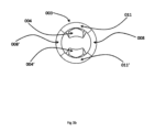
図6、図6a、図6bは、丸みを帯びた形状の形態のスナップ係止カバー(003)を示している。両側に2つのスナップ係止舌片(004,004’,004’’,004’’’)が構成されており(図6a、図6bでは一方の側は見えない)、スナップ係止カバー(003)の一方の側に、スナップ係止ハードストップ(008)と、2つのスナップ係止カバースカート(011,011’)とが構成されていて、可視である。したがって、接続手段(例えば2つの医療装置パーツの支柱)は、2つの医療装置パーツの接続のために、一方の側からスナップ係止カバー(003)内に係合されることになる。ある種の詳細は、図の裏側にあるため、見えない。 Figures 6, 6a, 6b show the snap-lock cover (003) in the form of a rounded shape. Two snap-lock tongues (004, 004', 004'', 004''') are configured on both sides (one side is not visible in Figures 6a, 6b), and on one side of the snap-lock cover (003) a snap-lock hard stop (008) and two snap-lock cover skirts (011, 011') are configured and visible. Thus, the connection means (e.g. posts of two medical device parts) will be engaged in the snap-lock cover (003) from one side for the connection of two medical device parts. Certain details are not visible because they are on the reverse side of the figures.
特に、図6は、4つのスナップ係止舌片(004,004’,004’’,004’’’)と、2つのスナップ係止ハードストップ(008,008’)と、2つのスナップ係止カバースカート(011,011’は見えない)とを備える丸みを帯びた形状の形態のスナップ係止カバー(003)を示している。したがって、接続手段(例えば2つの医療装置パーツの支柱)は、2つの医療装置パーツの接続のために、一方の側からスナップ係止カバー(003)内に係合されることになる。 In particular, FIG. 6 shows the snap-lock cover (003) in the form of a rounded shape with four snap-lock tongues (004, 004', 004'', 004'''), two snap-lock hard stops (008, 008') and two snap-lock cover skirts (011, 011' not visible). Thus, the connection means (e.g. posts of two medical device parts) are engaged into the snap-lock cover (003) from one side for connection of the two medical device parts.
図6aは、特に図6の側面図を示しており、2つのスナップ係止舌片(004’,004’’’)および1つのスナップ係止ハードストップ(008’)などの機構は見えない。 Figure 6a specifically shows a side view of Figure 6, where features such as the two snap-lock tongues (004', 004''') and one snap-lock hard stop (008') are not visible.
図6bは、特に図6の等角図を示し、2つのスナップ係止舌片(004’,004’’’)、1つのスナップ係止ハードストップ(008’)、および1つのスナップ係止カバースカート(011’)などの機構は見えない。 Figure 6b specifically shows an isometric view of Figure 6, with features such as the two snap-lock tongues (004', 004'''), one snap-lock hard stop (008'), and one snap-lock cover skirt (011') not visible.
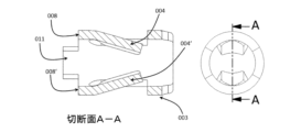
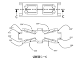
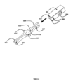
図7~図9cは、接続手段(例えば、支柱001,002)が、互いに異なる側からスナップ係止カバー(003)に導入され、係合される、本開示によるスナップ係止カバー(003)を示す。各支柱(001,002)は、2つの支柱舌片ストップ(009,009’,009’’,009’’’)と、2つの支柱ハードストップ(007,007’)とを備えている。矢印は、支柱(001,002)がスナップ係止カバー(003)に導入される方向を示している。 7-9c show a snap lock cover (003) according to the present disclosure, where the connection means (e.g. posts 001, 002) are introduced into and engaged with the snap lock cover (003) from different sides. Each post (001, 002) has two post tongue stops (009, 009', 009'', 009''') and two post hard stops (007, 007'). The arrows indicate the direction in which the posts (001, 002) are introduced into the snap lock cover (003).
図8は、図7の切断面(C-C)を示しており、内向きに向けられたスナップ係止舌片(004,004’,004’’,004’’’)の詳細を示している。オプション機構のスナップ係止ハードストップ(008,008’,008’’,008’’’)およびスナップ係止カバースカート(011,011’)もまた示されている。 Figure 8 shows a cutaway (C-C) of Figure 7, detailing the inwardly directed snap-lock tangs (004, 004', 004'', 004'''). Also shown are optional snap-lock hard stops (008, 008', 008'', 008''') and snap-lock cover skirts (011, 011').
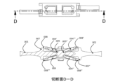
図9、図9a~図9cは、本開示によるスナップ係止カバーを使用する異なる医療装置パーツの接続支柱の本開示による異なる実施形態を示す。したがって、支柱舌片ストップ(009,009’,009’’,009’’’)は、各々の支柱(001,002)の遠位に位置決めされ、スナップ係止舌片が、各々の支柱(001,002)がスナップ係止カバー(003)に導入される側からさらに離れている状態で係止されている。スナップ係止カバー(003)の同一の側または異なる側、例えば180°反対側に、2つのスナップ係止舌片(004)のみが含まれていてもよい。スナップ係止舌片の位置を回動させる他の角度を想定することができる。 9, 9a-9c show different embodiments of the present disclosure of connecting posts of different medical device parts using a snap-lock cover according to the present disclosure. Thus, the post tongue stops (009, 009', 009'', 009''') are positioned distal to each post (001, 002) and the snap-lock tongues are locked further away from the side where each post (001, 002) is introduced into the snap-lock cover (003). Only two snap-lock tongues (004) may be included on the same or different sides of the snap-lock cover (003), e.g., 180° opposite. Other angles of rotation of the snap-lock tongue position can be envisioned.
図9bには、完全に組み立てられた装置が示されている。図9cは、接続装置の切断面(D-D)を含み、支柱はスナップ係止舌片(004,004’,004’’,004’’’)と、支柱舌片ストップ(009,009’,009’’,009’’’)とにより係止されて示されている。 Figure 9b shows the fully assembled device. Figure 9c includes a cutaway (D-D) of the connection device, with the posts shown engaged by the snap lock tongues (004, 004', 004'', 004''') and the post tongue stops (009, 009', 009'', 009''').
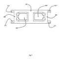
図10、図10a、図10bは、スナップ係止カバーが矩形の形状を有する、本開示によるスナップ係止カバーの異なる実施形態を示している。これは、支柱(001,002)とスナップ係止カバー(003)とが中空領域なしで極めて密に接続されているという利点を有する。スナップ係止舌片(004)、スナップ係止カバースカート(011,011’)、およびスナップ係止ハードストップ(008,008’)が図示されている。 Figures 10, 10a and 10b show different embodiments of the snap lock cover according to the present disclosure, where the snap lock cover has a rectangular shape. This has the advantage that the posts (001, 002) and the snap lock cover (003) are very tightly connected without hollow areas. The snap lock tongues (004), the snap lock cover skirts (011, 011') and the snap lock hard stops (008, 008') are shown.
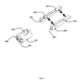
図11は、2つの支柱(001,002)に位置決めされた支柱位置合わせ手段(010,010’)の一実施形態を示し、これは、2つの支柱の正確な位置合わせおよびスナップ係止カバー(003)内での適正な位置決めを容易にする。矢印は、支柱を組み立ててスナップ係止カバー(003、図11に図示されていない)に接続する際の支柱(001,002)の移動を示している。ここで、支柱の配向は、上向きまたは下向きが、レーザ切断された当初の管(例えば、ニチノール管)の外側または内側である。したがって、2つの支柱は、切断側同士で位置合わせされ、当初の管に関して、切断側同士が位置合わせされ、外側の管側および内側の管側は、それぞれ、上向きおよび下向き、またはその逆で向かい合っている。切断された管に関して、切断に関して相並んで組み立てられていることを示すこともできる。 Figure 11 shows an embodiment of the post alignment means (010, 010') positioned on the two posts (001, 002) to facilitate accurate alignment of the two posts and proper positioning within the snap lock cover (003). The arrows indicate the movement of the posts (001, 002) when they are assembled and connected to the snap lock cover (003, not shown in Figure 11). Here, the orientation of the posts is up or down on the outside or inside of the original laser cut tube (e.g., Nitinol tube). Thus, the two posts are aligned cut side to cut side with respect to the original tube, with the outside tube side and the inside tube side facing up and down, respectively, or vice versa. With respect to the cut tube, they can also be shown assembled side by side with respect to the cut.
図11aは、支柱(001,002)に被せられ、2つの医療装置パーツを簡単かつ安全に接続するスナップ係止カバー(003)への、支柱位置合わせ手段(010,010’)を含む支柱(001,002)の接続プロセスを示す図である。図11bは、完全に組み立てられたパーツ(001,002,003)を示している。 Figure 11a shows the connection process of the posts (001, 002) including the post alignment means (010, 010') to the snap lock cover (003) that fits over the posts (001, 002) and connects the two medical device parts easily and safely. Figure 11b shows the fully assembled parts (001, 002, 003).
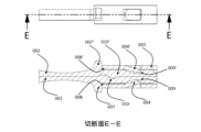
図12は、図11bの切断面(E-E)であり、スナップ係止カバー(003)によって接続された支柱(001,002)を示している。 Figure 12 is a cross-section (E-E) of Figure 11b, showing the posts (001, 002) connected by a snap-lock cover (003).
図13は、この図ではスナップ係止カバー(003)の遠位端部にあるスナップ係止ハードストップ(008,008’)の変形例を示している。したがって、スナップ係止ハードストップは、スナップ係止カバーの近位端部または遠位端部のいずれかに配置することができ、近位位置は、支柱がスナップ係止カバー(003)に導入される側を示し、スナップ係止ハードストップの遠位位置は、支柱のスナップ係止カバー(003)への導入側と反対側の側を示す。スナップ係止ハードストップは1つ以上であってよく、支柱導入側の反対側に位置決めされる場合には、1つ以上のスナップ係止ハードストップであってよい(例えば、図13、図13a、図13b、図13cを参照)。 Figure 13 shows a variation of the snap-lock hard stop (008, 008'), which in this view is at the distal end of the snap-lock cover (003). Thus, the snap-lock hard stop can be located at either the proximal or distal end of the snap-lock cover, with the proximal location indicating the side where the post is introduced into the snap-lock cover (003) and the distal location of the snap-lock hard stop indicating the side opposite the side where the post is introduced into the snap-lock cover (003). There can be more than one snap-lock hard stop, and there can be more than one snap-lock hard stop when positioned opposite the post introduction side (see e.g. Figures 13, 13a, 13b, 13c).
図14は、支柱(001,002)と共に、図13cのスナップ係止カバー(003)を示し、矢印によって支柱(001,002)の位置合わせと、そのアセンブリ(図14a、図14b)とを示している。 Figure 14 shows the snap lock cover (003) of Figure 13c together with the posts (001, 002) and the arrows showing the alignment of the posts (001, 002) and their assembly (Figures 14a, 14b).
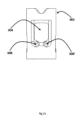
図15、図15a、図15bおよび図15c(切断面F-F)は、本開示による変形例を示し、スナップ係止ハードストップ(008,008’)は、スナップ係止カバー(003)の内部に位置決めされ、図16に示すように切断または彫刻された、支柱(001,002)に設けられた特別な設計上の機構としての対応部分(支柱ハードストップ007,007’)にたどり着く。
Figures 15, 15a, 15b and 15c (cut plane F-F) show a variation according to the present disclosure, where the snap lock hard stop (008, 008') is positioned inside the snap lock cover (003) and reaches to its counterpart (post
図16aおよび図16bは、支柱(001,002)の組立て(矢印を参照)と、支柱(001,002)とスナップ係止カバー(003)および特別に設計されたスナップ係止ハードストップ(008)との接続を示している。 Figures 16a and 16b show the assembly of the posts (001, 002) (see arrows) and their connection to the snap-lock cover (003) and specially designed snap-lock hardstop (008).
001 第1の支柱
002 第2の支柱
003 スナップ係止カバー
004/004’/004’’/004’’’ スナップ係止舌片
005 第1のステント
006 第2のステント
007/007’ 支柱ハードストップ
008/008’/008’’/008’’’ スナップ係止ハードストップ
009/009’/009’’/009’’’ 支柱舌片ストップ
010/010’ 支柱位置合わせ手段
011/011’ スナップ係止カバースカート
001
Claims (7)
第1の接続機構を有する第1のパーツと、
第2の接続機構を有する第2のパーツと、
筒状のスナップ係止カバーと、
を備え、
前記第1の接続機構および前記第2の接続機構はそれぞれ、支柱と、支柱の先端に形成された支柱舌片ストップと、を有し、
前記スナップ係止カバーは、2つのスナップ係止舌片を有し、前記2つのスナップ係止舌片は、筒状の前記スナップ係止カバーの内部に向けられており、
前記第1の接続機構の支柱と前記第2の接続機構の支柱とが前記スナップ係止カバーの内部に同一方向に一緒に導入され、2つの前記支柱舌片ストップが前記スナップ係止舌片の可撓性により前記スナップ係止舌片を通過し、前記スナップ係止舌片に係止される、2パーツ医療装置。 1. A two-part medical device comprising:
a first part having a first connection mechanism ;
a second part having a second connection mechanism ;
A cylindrical snap-lock cover;
Equipped with
Each of the first connection mechanism and the second connection mechanism includes a support and a support tongue stop formed at a tip of the support,
The snap-lock cover has two snap-lock tongues, and the two snap-lock tongues are directed toward the inside of the cylindrical snap-lock cover;
A two-part medical device, wherein the posts of the first connection mechanism and the posts of the second connection mechanism are introduced together in the same direction inside the snap-lock cover, and the two post tongue stops pass through the snap-lock tongue due to the flexibility of the snap-lock tongue and are engaged with the snap-lock tongue .
前記第2のパーツは、第2のステントである、the second part is a second stent;
請求項1記載の2パーツ医療装置。10. The two-part medical device of claim 1.
置換弁と、
請求項2記載の2パーツ医療装置と、
を備える、
心臓弁置換プロテーゼ。 1. A heart valve replacement prosthesis comprising:
A replacement valve;
A two-part medical device according to claim 2 ;
Equipped with
Heart valve replacement prosthesis.
Applications Claiming Priority (3)
| Application Number | Priority Date | Filing Date | Title |
|---|---|---|---|
| EP19215990 | 2019-12-13 | ||
| EP19215990.3 | 2019-12-13 | ||
| PCT/EP2020/085708 WO2021116377A1 (en) | 2019-12-13 | 2020-12-11 | Connecting device for medical devices |
Publications (2)
| Publication Number | Publication Date |
|---|---|
| JP2023505698A JP2023505698A (en) | 2023-02-10 |
| JP7630516B2 true JP7630516B2 (en) | 2025-02-17 |
Family
ID=68916381
Family Applications (1)
| Application Number | Title | Priority Date | Filing Date |
|---|---|---|---|
| JP2022535565A Active JP7630516B2 (en) | 2019-12-13 | 2020-12-11 | Medical Device Connections |
Country Status (7)
| Country | Link |
|---|---|
| US (1) | US20230019677A1 (en) |
| EP (2) | EP4072473B1 (en) |
| JP (1) | JP7630516B2 (en) |
| CN (1) | CN114765949B (en) |
| AU (1) | AU2020403542B2 (en) |
| CA (1) | CA3157212A1 (en) |
| WO (1) | WO2021116377A1 (en) |
Citations (2)
| Publication number | Priority date | Publication date | Assignee | Title |
|---|---|---|---|---|
| US20070233117A1 (en) | 2006-02-21 | 2007-10-04 | Life Spine, Llc | Structure for joining and retaining multi-part orthopedic implants |
| WO2019158628A1 (en) | 2018-02-15 | 2019-08-22 | Tricares SAS | Stent and replacement heart valve prosthesis with improved fixation features |
Family Cites Families (8)
| Publication number | Priority date | Publication date | Assignee | Title |
|---|---|---|---|---|
| DE4438620A1 (en) * | 1994-05-02 | 1995-11-09 | Laghaollah Dr Elhami | Joint prosthesis and device for making a bore in at least one joint head |
| US7972363B2 (en) * | 2005-04-12 | 2011-07-05 | Moskowitz Ahmnon D | Bi-directional fixating/locking transvertebral body screw/intervertebral cage stand-alone constructs and posterior cervical and lumbar interarticulating joint stapling guns and devices for spinal fusion |
| US7914574B2 (en) * | 2005-08-02 | 2011-03-29 | Reva Medical, Inc. | Axially nested slide and lock expandable device |
| US20090275945A1 (en) * | 2008-04-30 | 2009-11-05 | Exploramed Nc4, Inc. | Sheaths for extra-articular implantable systems |
| SG10201609392XA (en) * | 2012-12-31 | 2017-01-27 | Edwards Lifesciences Corp | Post-implant expandable surgical heart valve configurations |
| CN111329541B (en) * | 2015-11-17 | 2023-09-19 | 波士顿科学国际有限公司 | Implantable devices and delivery systems for reshaping cardiac annulus |
| US11026785B2 (en) * | 2017-06-05 | 2021-06-08 | Edwards Lifesciences Corporation | Mechanically expandable heart valve |
| US11051934B2 (en) * | 2018-02-28 | 2021-07-06 | Edwards Lifesciences Corporation | Prosthetic mitral valve with improved anchors and seal |
-
2020
- 2020-12-11 AU AU2020403542A patent/AU2020403542B2/en active Active
- 2020-12-11 US US17/783,868 patent/US20230019677A1/en active Pending
- 2020-12-11 CN CN202080083422.3A patent/CN114765949B/en active Active
- 2020-12-11 JP JP2022535565A patent/JP7630516B2/en active Active
- 2020-12-11 CA CA3157212A patent/CA3157212A1/en active Pending
- 2020-12-11 EP EP20820963.5A patent/EP4072473B1/en active Active
- 2020-12-11 EP EP25152772.7A patent/EP4548884A3/en active Pending
- 2020-12-11 WO PCT/EP2020/085708 patent/WO2021116377A1/en not_active Ceased
Patent Citations (2)
| Publication number | Priority date | Publication date | Assignee | Title |
|---|---|---|---|---|
| US20070233117A1 (en) | 2006-02-21 | 2007-10-04 | Life Spine, Llc | Structure for joining and retaining multi-part orthopedic implants |
| WO2019158628A1 (en) | 2018-02-15 | 2019-08-22 | Tricares SAS | Stent and replacement heart valve prosthesis with improved fixation features |
Also Published As
| Publication number | Publication date |
|---|---|
| EP4072473B1 (en) | 2025-01-22 |
| CN114765949A (en) | 2022-07-19 |
| AU2020403542A1 (en) | 2022-06-16 |
| CA3157212A1 (en) | 2021-06-17 |
| WO2021116377A1 (en) | 2021-06-17 |
| JP2023505698A (en) | 2023-02-10 |
| CN114765949B (en) | 2025-08-26 |
| EP4548884A2 (en) | 2025-05-07 |
| AU2020403542B2 (en) | 2025-09-11 |
| EP4548884A3 (en) | 2025-07-23 |
| EP4072473A1 (en) | 2022-10-19 |
| EP4072473C0 (en) | 2025-01-22 |
| US20230019677A1 (en) | 2023-01-19 |
Similar Documents
| Publication | Publication Date | Title |
|---|---|---|
| US20240058122A1 (en) | Three part stent second generation | |
| US12144729B2 (en) | Implantable transcatheter intracardiac devices and methods for treating incompetent atrioventricular valves | |
| CN110831546B (en) | Valved stent and delivery system for in situ replacement of dysfunctional heart valves | |
| EP3200726B1 (en) | A heart valve treatment device | |
| US9795476B2 (en) | Collapsible heart valve with angled frame | |
| CN109789019A (en) | Heart valve paired wire ring and system | |
| KR20230012397A (en) | artificial heart valve | |
| JP2025071166A (en) | Prosthetic heart valve devices, systems and methods | |
| US20250143878A1 (en) | Transcatheter valve introducer system and methods | |
| JP7630516B2 (en) | Medical Device Connections | |
| JP2025514517A (en) | Prosthetic heart valves, systems and methods | |
| JP2025540736A (en) | Heart Valve Delivery Device | |
| CN118251195A (en) | Valve prostheses and transcatheter delivery systems |
Legal Events
| Date | Code | Title | Description |
|---|---|---|---|
| A621 | Written request for application examination |
Free format text: JAPANESE INTERMEDIATE CODE: A621 Effective date: 20231128 |
|
| A977 | Report on retrieval |
Free format text: JAPANESE INTERMEDIATE CODE: A971007 Effective date: 20240821 |
|
| A131 | Notification of reasons for refusal |
Free format text: JAPANESE INTERMEDIATE CODE: A131 Effective date: 20240903 |
|
| A521 | Request for written amendment filed |
Free format text: JAPANESE INTERMEDIATE CODE: A523 Effective date: 20241129 |
|
| TRDD | Decision of grant or rejection written | ||
| A01 | Written decision to grant a patent or to grant a registration (utility model) |
Free format text: JAPANESE INTERMEDIATE CODE: A01 Effective date: 20250106 |
|
| A61 | First payment of annual fees (during grant procedure) |
Free format text: JAPANESE INTERMEDIATE CODE: A61 Effective date: 20250204 |
|
| R150 | Certificate of patent or registration of utility model |
Ref document number: 7630516 Country of ref document: JP Free format text: JAPANESE INTERMEDIATE CODE: R150 |