EP3200726B1 - A heart valve treatment device - Google Patents
A heart valve treatment device Download PDFInfo
- Publication number
- EP3200726B1 EP3200726B1 EP15770921.3A EP15770921A EP3200726B1 EP 3200726 B1 EP3200726 B1 EP 3200726B1 EP 15770921 A EP15770921 A EP 15770921A EP 3200726 B1 EP3200726 B1 EP 3200726B1
- Authority
- EP
- European Patent Office
- Prior art keywords
- valve
- anchor
- support
- leaflets
- ring
- Prior art date
- Legal status (The legal status is an assumption and is not a legal conclusion. Google has not performed a legal analysis and makes no representation as to the accuracy of the status listed.)
- Active
Links
Images


Classifications
-
- A—HUMAN NECESSITIES
- A61—MEDICAL OR VETERINARY SCIENCE; HYGIENE
- A61F—FILTERS IMPLANTABLE INTO BLOOD VESSELS; PROSTHESES; DEVICES PROVIDING PATENCY TO, OR PREVENTING COLLAPSING OF, TUBULAR STRUCTURES OF THE BODY, e.g. STENTS; ORTHOPAEDIC, NURSING OR CONTRACEPTIVE DEVICES; FOMENTATION; TREATMENT OR PROTECTION OF EYES OR EARS; BANDAGES, DRESSINGS OR ABSORBENT PADS; FIRST-AID KITS
- A61F2/00—Filters implantable into blood vessels; Prostheses, i.e. artificial substitutes or replacements for parts of the body; Appliances for connecting them with the body; Devices providing patency to, or preventing collapsing of, tubular structures of the body, e.g. stents
- A61F2/02—Prostheses implantable into the body
- A61F2/24—Heart valves ; Vascular valves, e.g. venous valves; Heart implants, e.g. passive devices for improving the function of the native valve or the heart muscle; Transmyocardial revascularisation [TMR] devices; Valves implantable in the body
- A61F2/2442—Annuloplasty rings or inserts for correcting the valve shape; Implants for improving the function of a native heart valve
- A61F2/246—Devices for obstructing a leak through a native valve in a closed condition
-
- A—HUMAN NECESSITIES
- A61—MEDICAL OR VETERINARY SCIENCE; HYGIENE
- A61F—FILTERS IMPLANTABLE INTO BLOOD VESSELS; PROSTHESES; DEVICES PROVIDING PATENCY TO, OR PREVENTING COLLAPSING OF, TUBULAR STRUCTURES OF THE BODY, e.g. STENTS; ORTHOPAEDIC, NURSING OR CONTRACEPTIVE DEVICES; FOMENTATION; TREATMENT OR PROTECTION OF EYES OR EARS; BANDAGES, DRESSINGS OR ABSORBENT PADS; FIRST-AID KITS
- A61F2/00—Filters implantable into blood vessels; Prostheses, i.e. artificial substitutes or replacements for parts of the body; Appliances for connecting them with the body; Devices providing patency to, or preventing collapsing of, tubular structures of the body, e.g. stents
- A61F2/02—Prostheses implantable into the body
- A61F2/24—Heart valves ; Vascular valves, e.g. venous valves; Heart implants, e.g. passive devices for improving the function of the native valve or the heart muscle; Transmyocardial revascularisation [TMR] devices; Valves implantable in the body
- A61F2/2412—Heart valves ; Vascular valves, e.g. venous valves; Heart implants, e.g. passive devices for improving the function of the native valve or the heart muscle; Transmyocardial revascularisation [TMR] devices; Valves implantable in the body with soft flexible valve members, e.g. tissue valves shaped like natural valves
-
- A—HUMAN NECESSITIES
- A61—MEDICAL OR VETERINARY SCIENCE; HYGIENE
- A61F—FILTERS IMPLANTABLE INTO BLOOD VESSELS; PROSTHESES; DEVICES PROVIDING PATENCY TO, OR PREVENTING COLLAPSING OF, TUBULAR STRUCTURES OF THE BODY, e.g. STENTS; ORTHOPAEDIC, NURSING OR CONTRACEPTIVE DEVICES; FOMENTATION; TREATMENT OR PROTECTION OF EYES OR EARS; BANDAGES, DRESSINGS OR ABSORBENT PADS; FIRST-AID KITS
- A61F2/00—Filters implantable into blood vessels; Prostheses, i.e. artificial substitutes or replacements for parts of the body; Appliances for connecting them with the body; Devices providing patency to, or preventing collapsing of, tubular structures of the body, e.g. stents
- A61F2/02—Prostheses implantable into the body
- A61F2/24—Heart valves ; Vascular valves, e.g. venous valves; Heart implants, e.g. passive devices for improving the function of the native valve or the heart muscle; Transmyocardial revascularisation [TMR] devices; Valves implantable in the body
- A61F2/2427—Devices for manipulating or deploying heart valves during implantation
- A61F2/2436—Deployment by retracting a sheath
-
- A—HUMAN NECESSITIES
- A61—MEDICAL OR VETERINARY SCIENCE; HYGIENE
- A61F—FILTERS IMPLANTABLE INTO BLOOD VESSELS; PROSTHESES; DEVICES PROVIDING PATENCY TO, OR PREVENTING COLLAPSING OF, TUBULAR STRUCTURES OF THE BODY, e.g. STENTS; ORTHOPAEDIC, NURSING OR CONTRACEPTIVE DEVICES; FOMENTATION; TREATMENT OR PROTECTION OF EYES OR EARS; BANDAGES, DRESSINGS OR ABSORBENT PADS; FIRST-AID KITS
- A61F2/00—Filters implantable into blood vessels; Prostheses, i.e. artificial substitutes or replacements for parts of the body; Appliances for connecting them with the body; Devices providing patency to, or preventing collapsing of, tubular structures of the body, e.g. stents
- A61F2/02—Prostheses implantable into the body
- A61F2/24—Heart valves ; Vascular valves, e.g. venous valves; Heart implants, e.g. passive devices for improving the function of the native valve or the heart muscle; Transmyocardial revascularisation [TMR] devices; Valves implantable in the body
- A61F2/2442—Annuloplasty rings or inserts for correcting the valve shape; Implants for improving the function of a native heart valve
- A61F2/2451—Inserts in the coronary sinus for correcting the valve shape
-
- A—HUMAN NECESSITIES
- A61—MEDICAL OR VETERINARY SCIENCE; HYGIENE
- A61F—FILTERS IMPLANTABLE INTO BLOOD VESSELS; PROSTHESES; DEVICES PROVIDING PATENCY TO, OR PREVENTING COLLAPSING OF, TUBULAR STRUCTURES OF THE BODY, e.g. STENTS; ORTHOPAEDIC, NURSING OR CONTRACEPTIVE DEVICES; FOMENTATION; TREATMENT OR PROTECTION OF EYES OR EARS; BANDAGES, DRESSINGS OR ABSORBENT PADS; FIRST-AID KITS
- A61F2/00—Filters implantable into blood vessels; Prostheses, i.e. artificial substitutes or replacements for parts of the body; Appliances for connecting them with the body; Devices providing patency to, or preventing collapsing of, tubular structures of the body, e.g. stents
- A61F2/02—Prostheses implantable into the body
- A61F2/24—Heart valves ; Vascular valves, e.g. venous valves; Heart implants, e.g. passive devices for improving the function of the native valve or the heart muscle; Transmyocardial revascularisation [TMR] devices; Valves implantable in the body
- A61F2/2442—Annuloplasty rings or inserts for correcting the valve shape; Implants for improving the function of a native heart valve
- A61F2/2454—Means for preventing inversion of the valve leaflets, e.g. chordae tendineae prostheses
- A61F2/2457—Chordae tendineae prostheses
-
- A—HUMAN NECESSITIES
- A61—MEDICAL OR VETERINARY SCIENCE; HYGIENE
- A61F—FILTERS IMPLANTABLE INTO BLOOD VESSELS; PROSTHESES; DEVICES PROVIDING PATENCY TO, OR PREVENTING COLLAPSING OF, TUBULAR STRUCTURES OF THE BODY, e.g. STENTS; ORTHOPAEDIC, NURSING OR CONTRACEPTIVE DEVICES; FOMENTATION; TREATMENT OR PROTECTION OF EYES OR EARS; BANDAGES, DRESSINGS OR ABSORBENT PADS; FIRST-AID KITS
- A61F2/00—Filters implantable into blood vessels; Prostheses, i.e. artificial substitutes or replacements for parts of the body; Appliances for connecting them with the body; Devices providing patency to, or preventing collapsing of, tubular structures of the body, e.g. stents
- A61F2/02—Prostheses implantable into the body
- A61F2/24—Heart valves ; Vascular valves, e.g. venous valves; Heart implants, e.g. passive devices for improving the function of the native valve or the heart muscle; Transmyocardial revascularisation [TMR] devices; Valves implantable in the body
- A61F2/2442—Annuloplasty rings or inserts for correcting the valve shape; Implants for improving the function of a native heart valve
- A61F2/2466—Delivery devices therefor
-
- A—HUMAN NECESSITIES
- A61—MEDICAL OR VETERINARY SCIENCE; HYGIENE
- A61F—FILTERS IMPLANTABLE INTO BLOOD VESSELS; PROSTHESES; DEVICES PROVIDING PATENCY TO, OR PREVENTING COLLAPSING OF, TUBULAR STRUCTURES OF THE BODY, e.g. STENTS; ORTHOPAEDIC, NURSING OR CONTRACEPTIVE DEVICES; FOMENTATION; TREATMENT OR PROTECTION OF EYES OR EARS; BANDAGES, DRESSINGS OR ABSORBENT PADS; FIRST-AID KITS
- A61F2/00—Filters implantable into blood vessels; Prostheses, i.e. artificial substitutes or replacements for parts of the body; Appliances for connecting them with the body; Devices providing patency to, or preventing collapsing of, tubular structures of the body, e.g. stents
- A61F2/95—Instruments specially adapted for placement or removal of stents or stent-grafts
- A61F2/9517—Instruments specially adapted for placement or removal of stents or stent-grafts handle assemblies therefor
-
- A—HUMAN NECESSITIES
- A61—MEDICAL OR VETERINARY SCIENCE; HYGIENE
- A61B—DIAGNOSIS; SURGERY; IDENTIFICATION
- A61B17/00—Surgical instruments, devices or methods
- A61B17/04—Surgical instruments, devices or methods for suturing wounds; Holders or packages for needles or suture materials
- A61B17/0401—Suture anchors, buttons or pledgets, i.e. means for attaching sutures to bone, cartilage or soft tissue; Instruments for applying or removing suture anchors
- A61B2017/0419—H-fasteners
-
- A—HUMAN NECESSITIES
- A61—MEDICAL OR VETERINARY SCIENCE; HYGIENE
- A61B—DIAGNOSIS; SURGERY; IDENTIFICATION
- A61B17/00—Surgical instruments, devices or methods
- A61B17/04—Surgical instruments, devices or methods for suturing wounds; Holders or packages for needles or suture materials
- A61B17/0401—Suture anchors, buttons or pledgets, i.e. means for attaching sutures to bone, cartilage or soft tissue; Instruments for applying or removing suture anchors
- A61B2017/044—Suture anchors, buttons or pledgets, i.e. means for attaching sutures to bone, cartilage or soft tissue; Instruments for applying or removing suture anchors with a threaded shaft, e.g. screws
-
- A—HUMAN NECESSITIES
- A61—MEDICAL OR VETERINARY SCIENCE; HYGIENE
- A61B—DIAGNOSIS; SURGERY; IDENTIFICATION
- A61B17/00—Surgical instruments, devices or methods
- A61B17/04—Surgical instruments, devices or methods for suturing wounds; Holders or packages for needles or suture materials
- A61B17/0401—Suture anchors, buttons or pledgets, i.e. means for attaching sutures to bone, cartilage or soft tissue; Instruments for applying or removing suture anchors
- A61B2017/0464—Suture anchors, buttons or pledgets, i.e. means for attaching sutures to bone, cartilage or soft tissue; Instruments for applying or removing suture anchors for soft tissue
-
- A—HUMAN NECESSITIES
- A61—MEDICAL OR VETERINARY SCIENCE; HYGIENE
- A61B—DIAGNOSIS; SURGERY; IDENTIFICATION
- A61B17/00—Surgical instruments, devices or methods
- A61B17/22—Implements for squeezing-off ulcers or the like on inner organs of the body; Implements for scraping-out cavities of body organs, e.g. bones; for invasive removal or destruction of calculus using mechanical vibrations; for removing obstructions in blood vessels, not otherwise provided for
- A61B2017/22038—Implements for squeezing-off ulcers or the like on inner organs of the body; Implements for scraping-out cavities of body organs, e.g. bones; for invasive removal or destruction of calculus using mechanical vibrations; for removing obstructions in blood vessels, not otherwise provided for with a guide wire
- A61B2017/22042—Details of the tip of the guide wire
- A61B2017/22044—Details of the tip of the guide wire with a pointed tip
-
- A—HUMAN NECESSITIES
- A61—MEDICAL OR VETERINARY SCIENCE; HYGIENE
- A61B—DIAGNOSIS; SURGERY; IDENTIFICATION
- A61B17/00—Surgical instruments, devices or methods
- A61B17/22—Implements for squeezing-off ulcers or the like on inner organs of the body; Implements for scraping-out cavities of body organs, e.g. bones; for invasive removal or destruction of calculus using mechanical vibrations; for removing obstructions in blood vessels, not otherwise provided for
- A61B2017/22038—Implements for squeezing-off ulcers or the like on inner organs of the body; Implements for scraping-out cavities of body organs, e.g. bones; for invasive removal or destruction of calculus using mechanical vibrations; for removing obstructions in blood vessels, not otherwise provided for with a guide wire
- A61B2017/22047—Means for immobilising the guide wire in the patient
-
- A—HUMAN NECESSITIES
- A61—MEDICAL OR VETERINARY SCIENCE; HYGIENE
- A61F—FILTERS IMPLANTABLE INTO BLOOD VESSELS; PROSTHESES; DEVICES PROVIDING PATENCY TO, OR PREVENTING COLLAPSING OF, TUBULAR STRUCTURES OF THE BODY, e.g. STENTS; ORTHOPAEDIC, NURSING OR CONTRACEPTIVE DEVICES; FOMENTATION; TREATMENT OR PROTECTION OF EYES OR EARS; BANDAGES, DRESSINGS OR ABSORBENT PADS; FIRST-AID KITS
- A61F2/00—Filters implantable into blood vessels; Prostheses, i.e. artificial substitutes or replacements for parts of the body; Appliances for connecting them with the body; Devices providing patency to, or preventing collapsing of, tubular structures of the body, e.g. stents
- A61F2/02—Prostheses implantable into the body
- A61F2/24—Heart valves ; Vascular valves, e.g. venous valves; Heart implants, e.g. passive devices for improving the function of the native valve or the heart muscle; Transmyocardial revascularisation [TMR] devices; Valves implantable in the body
- A61F2/2412—Heart valves ; Vascular valves, e.g. venous valves; Heart implants, e.g. passive devices for improving the function of the native valve or the heart muscle; Transmyocardial revascularisation [TMR] devices; Valves implantable in the body with soft flexible valve members, e.g. tissue valves shaped like natural valves
- A61F2/2418—Scaffolds therefor, e.g. support stents
-
- A—HUMAN NECESSITIES
- A61—MEDICAL OR VETERINARY SCIENCE; HYGIENE
- A61F—FILTERS IMPLANTABLE INTO BLOOD VESSELS; PROSTHESES; DEVICES PROVIDING PATENCY TO, OR PREVENTING COLLAPSING OF, TUBULAR STRUCTURES OF THE BODY, e.g. STENTS; ORTHOPAEDIC, NURSING OR CONTRACEPTIVE DEVICES; FOMENTATION; TREATMENT OR PROTECTION OF EYES OR EARS; BANDAGES, DRESSINGS OR ABSORBENT PADS; FIRST-AID KITS
- A61F2220/00—Fixations or connections for prostheses classified in groups A61F2/00 - A61F2/26 or A61F2/82 or A61F9/00 or A61F11/00 or subgroups thereof
- A61F2220/0008—Fixation appliances for connecting prostheses to the body
- A61F2220/0016—Fixation appliances for connecting prostheses to the body with sharp anchoring protrusions, e.g. barbs, pins, spikes
-
- A—HUMAN NECESSITIES
- A61—MEDICAL OR VETERINARY SCIENCE; HYGIENE
- A61F—FILTERS IMPLANTABLE INTO BLOOD VESSELS; PROSTHESES; DEVICES PROVIDING PATENCY TO, OR PREVENTING COLLAPSING OF, TUBULAR STRUCTURES OF THE BODY, e.g. STENTS; ORTHOPAEDIC, NURSING OR CONTRACEPTIVE DEVICES; FOMENTATION; TREATMENT OR PROTECTION OF EYES OR EARS; BANDAGES, DRESSINGS OR ABSORBENT PADS; FIRST-AID KITS
- A61F2230/00—Geometry of prostheses classified in groups A61F2/00 - A61F2/26 or A61F2/82 or A61F9/00 or A61F11/00 or subgroups thereof
- A61F2230/0063—Three-dimensional shapes
- A61F2230/0067—Three-dimensional shapes conical
-
- A—HUMAN NECESSITIES
- A61—MEDICAL OR VETERINARY SCIENCE; HYGIENE
- A61F—FILTERS IMPLANTABLE INTO BLOOD VESSELS; PROSTHESES; DEVICES PROVIDING PATENCY TO, OR PREVENTING COLLAPSING OF, TUBULAR STRUCTURES OF THE BODY, e.g. STENTS; ORTHOPAEDIC, NURSING OR CONTRACEPTIVE DEVICES; FOMENTATION; TREATMENT OR PROTECTION OF EYES OR EARS; BANDAGES, DRESSINGS OR ABSORBENT PADS; FIRST-AID KITS
- A61F2250/00—Special features of prostheses classified in groups A61F2/00 - A61F2/26 or A61F2/82 or A61F9/00 or A61F11/00 or subgroups thereof
- A61F2250/0004—Special features of prostheses classified in groups A61F2/00 - A61F2/26 or A61F2/82 or A61F9/00 or A61F11/00 or subgroups thereof adjustable
- A61F2250/001—Special features of prostheses classified in groups A61F2/00 - A61F2/26 or A61F2/82 or A61F9/00 or A61F11/00 or subgroups thereof adjustable for adjusting a diameter
-
- A—HUMAN NECESSITIES
- A61—MEDICAL OR VETERINARY SCIENCE; HYGIENE
- A61F—FILTERS IMPLANTABLE INTO BLOOD VESSELS; PROSTHESES; DEVICES PROVIDING PATENCY TO, OR PREVENTING COLLAPSING OF, TUBULAR STRUCTURES OF THE BODY, e.g. STENTS; ORTHOPAEDIC, NURSING OR CONTRACEPTIVE DEVICES; FOMENTATION; TREATMENT OR PROTECTION OF EYES OR EARS; BANDAGES, DRESSINGS OR ABSORBENT PADS; FIRST-AID KITS
- A61F2250/00—Special features of prostheses classified in groups A61F2/00 - A61F2/26 or A61F2/82 or A61F9/00 or A61F11/00 or subgroups thereof
- A61F2250/0058—Additional features; Implant or prostheses properties not otherwise provided for
- A61F2250/006—Additional features; Implant or prostheses properties not otherwise provided for modular
Definitions
- the invention relates to surgical devices, specifically for treating the heart.
- the invention relates to treating leaking heart valves, such as the atrioventricular (AV) valves.
- AV atrioventricular
- the heart contains four valves, two semilunar, the aortic and pulmonary valves, and two AV valves, the mitral and tricuspid valves.
- the heart fills with blood from the lungs and body when the AV valves are open.
- the AV valves close and prevent the blood from regurgitating backwards.
- the semilunar valves open when the heart pumps allowing the blood to flow into the aorta and main pulmonary artery.
- Dysfunction of the cardiac AV valves is common and can have profound clinical consequences. Failure of the AV valves to prevent regurgitation leads to an increase in the pressure of blood in the lungs or liver and reduces forward blood flow. Valvular dysfunction either results from a defect in the valve leaflet or supporting structure, or dilation of the fibrous ring supporting the valve. These factors lead to a failure of valve leaflets to meet one another, known as co-aptation, allowing the blood to travel in the wrong direction.
- Percutaneous techniques of valve repair have the advantage of being significantly less traumatic for the patient. During such procedures the valve repair is performed from within the heart, accessing the heart through a vein in the neck or the groin. Percutaneous procedures are performed under local anaesthetic and the incisions required to perform the procedures are extremely small. In addition, procedural times and recovery phases are also expected to be significantly less.
- Current attempts at percutaneous repair of leaking heart valves include insertion of a mitral valve support structure into a large cardiac vein known as the coronary sinus. Another is insertion of a stitch or clip into the mitral valve leaflets to hold them together. Another is insertion of a new prosthetic valve percutaneously.
- WO2006/064490 (Mednua ) describes a device with a generally cylindrical treatment element for location between a pair of valve leaflets. The device occludes the valve opening to resist retrograde flow. A tether extends into the ventricle and is connected to an anchor engaging the ventricle wall to support the device.
- WO2007/144865 also describes a device for treatment of a mitral valve, located in the region of co-aptation of the native leaflets.
- An anchor element anchors the device to the ventricle wall at the apex of the ventricle.
- WO2009/053952 (Mednua ) describes a percutaneous approach in which a treatment element is located between a pair of valve leaflets.
- a support has an anchor with for example a screw for engaging heart wall tissue.
- the treatment element comprises a hydrogel.
- US2013/0090728 and WO2006/111391 (Edwards Lifesciences AG ) describe an approach in which a mitral valve flow improvement device is percutaneously inserted. It has a prosthetic mitral valve leaflet, and a tissue-penetrating anchor. Blood flow from the left ventricle to the left atrium expands the prosthetic leaflet into the closed state so that it is umbrella-shaped. Support for the device is provided by either a stent-like support or by anchors which engage tissue within the heart.
- US2013/0325110 (Edwards Lifesciences Corp. ) describes devices for improving the functioning of a defective heart valve.
- a locking mechanism locks position of a co-apting element within the tricuspid valve (TV) and relative to a fixed anchor rail.
- the locking mechanism is a collet mechanism which locks a catheter onto the anchor rail, which runs through the catheter.
- the catheter and rail exit the subclavian vein (SV) at a puncture and remain implanted.
- the locking mechanism remains external, on a coil of the catheter/rail.
- An alternative arrangement is crimping the catheter onto the rail near the entry point.
- US2013/0338763 (Edwards Lifesciences ) also describes a heart valve co-aptation system with a locking collet. It also discloses anchoring of the co-aptation element using stent structures which straddle the tricuspid valve.
- WO2008/141322 discloses a heart valve implant on an anchor to engage tissue.
- EP2032080 discloses a device and methods for improving the function of a heart valve.
- US6332893 discloses a device for heart valve repair including at least one tension member.
- WO2005/087140 Percutaneous Cardiovascular ) describes a percutaneous heart valve prosthesis that has a valve body with a passage extending between the first and second ends of the valve body.
- the invention is directed towards providing an improved heart valve treatment device for percutaneous delivery.
- heart valve therapeutic device as set out in claim 1.
- Features of the disclosed device are set out in appended claims 2 to 14.
- the device comprises a stylet or a shaped or stiff collar arranged to provide a desired shape to the anchor.
- the actuator comprises control cables which are arranged to be moved axially under surgeon control.
- the device comprises an adjustment mechanism for varying individual chords connecting at least one coupler to the prosthetic valve element, and wherein the mechanism is arranged to shorten one or more chords and lengthen one or more other chord.
- the device comprises at least two couplers supporting the valve element on the anchor and the actuator is configured to set mutual separation of the couplers for configuration of the valve element.
- the actuator comprises a mechanism which shortens or lengthens linking of a support ring to the anchor, for tilting of the valve element.
- said ring is configured to engage atrium tissue and the valve element further comprises arms extending distally and axially.
- the device comprises an adjustment mechanism for varying said chords to adjust angle of the valve element with respect to the axis of the elongate anchor
- the valve element comprises prosthetic leaflets shaped for co-apting with native leaflets, and said prosthetic leaflets have together a smaller radial dimension for at least some of their length when the native leaflets are closed and a larger radial dimension when the native leaflets are open.
- the valve element comprises prosthetic valve leaflets that are supported to extend axially and radially outwardly towards the proximal end, with an apex facing into a heart chamber in use.
- the prosthetic valve leaflets are supported at their proximal end on a ring.
- the prosthetic valve leaflets are arranged so that in use blood flows through the centre of the valve.
- the support includes a radial support part which is radially distant from the anchor and is configured to engage atrial tissue on a proximal side of a valve.
- the radial support part comprises a ring extending around a device axis.
- the ring is on spokes.
- the ring is connected to chords extending from a coupler on an anchor.
- the ring comprises a proximal skirt arranged to prevent regurgitation between the native leaflets and the valve element.
- said skirt comprises a rim of material.
- said rim is of material which is the same material as material of valve element leaflets sewn or glued to a distal side of the radial support.
- the anchor is configured to rest against a posterior atrial wall upon deployment.
- the distal end of the support is deflectable such that position of the support can be altered to position the valve element to provide maximum reduction in regurgitation, the device comprising a mechanism for altering tension in elements within the support.
- the radial support abuts against a coupler of the valve attached to the anchor.
- the actuator further comprises a controller arranged to be implanted subcutaneously on the anchor to allow the position of the valve element to be changed after insertion.
- the device comprises an element for clamping the anchor to a wall through which the anchor passes.
- the valve element comprises leaflets shaped like native leaflets and having a ring-shaped support around its circumference.
- valve element is connected to the anchor by a coupler so that rotation of the support moves the valve to fit to the shape of the native valve.
- the support comprises a ring and one or more members extending distally such that they cross an AV valve in use, said members including a member interconnecting opposed side of the ring.
- the support includes a ring which is circular or oval or crescent-shaped.
- the device further comprises a sheath for delivering the anchor.
- the valve element comprises at least one fenestration configured to, in use, provide central flow such as washing jets to prevent or reduce thrombosis, wherein the fenestrations are at or adjacent to the base of the prosthetic valve element.
- fenestrations there are a plurality of fenestrations arranged circumferentially around a valve element axis, and wherein the fenestrations each have a cross-sectional area in the range of 0.5 mm 2 to 3 mm 2 , and they may have any suitable shape to suit the available areas such as circular, triangular, square or slit-like.
- valve element comprises leaflets which are cup-shaped and are secured directly to a support frame which attaches to the anchor.
- the invention provides a heart valve therapeutic kit comprising a plurality of devices as defined above in any embodiment, at least some of which are of different sizes to suit different sizes of patient valve defects.
- the invention provides a pacemaker comprising a device as defined above in any embodiment and pacemaker electrodes mounted on the anchor at a distal end of the anchor.
- the actuator is at a proximal end of the device.
- the prosthetic valve comprises a proximal coupler, and leaflets connected to the coupler by chords.
- the prosthetic valve comprises proximal and distal couplers connecting the valve to the elongate anchor.
- the actuator comprises control cables which are arranged to be moved axially under surgeon control.
- the device comprises an adjustment mechanism for varying individual chords connecting at least one coupler to the prosthetic valve leaflets.
- the mechanism is arranged to shorten one or more chords while lengthening one or more other chords or chords.
- the actuator comprises a rotating mechanism which shortens or lengthens chords upon rotation of one or more actuator device in a selected direction.
- the chords are attached to a coupler within the anchor which can be locked down onto the anchor.
- the device comprises an adjustment mechanism for varying said chords to adjust angle of the leaflets with respect to the axis of the elongate anchor.
- the prosthetic valve comprises valve leaflets that are supported to extend axially and radially outwardly towards the proximal end, with an apex facing into a heart chamber in use.
- the leaflets are supported at their proximal end on a ring.
- the leaflets are arranged so that in use blood flows through the centre of the valve.
- the device comprises a stylet arranged to be introduced by sliding along the anchor to provide a desired shape at the prosthetic valve.
- the prosthetic valve comprises a deformable element which is adapted to deform to seal the chamber.
- the deformable element is adapted to deform under heart chamber pressure.
- the device comprises an actuator for assisting or solely causing deformation of the deformable element.
- the deformable element comprises a stem which is configured to extend into a heart chamber, and a head which remains outside, the stem decreasing in volume and expanding the head during chamber higher pressure.
- the prosthetic valve comprises at least one fenestration configured to, in use, provide central flow such as washing jets to prevent or reduce thrombosis.
- the fenestrations are at or adjacent to the base of the prosthetic valve.
- the fenestrations each have a cross-sectional area in the range of 0.5 mm 2 to 3 mm 2 , and they may have any suitable shape to suit the available areas such as circular, triangular, square or slit-like.
- the device comprises a support at least part of which is radially distant from the anchor and is configured to engage tissue.
- the support comprises a ring extending around the device axis.
- the ring is on spokes.
- the support is arranged to be delivered over an anchor to rest against the posterior atrial wall.
- the support abuts against a coupler of the valve attached to the anchor.
- the invention provides a heart valve therapeutic kit comprising a plurality of devices as described above in any embodiment, at least some of which are of different sizes to suit different sizes of patient valve defects.
- a percutaneously-delivered valve made up of one or more leaflets, which can be made from porcine or bovine pericardium or other materials, which is attached to an anchor by one or more supports either on a ring on the atrial side of the native valve or directly to the anchor.
- the valve may be supported by the proximal portion of the anchor against the atrial wall. This can be re-enforced by the use of stylets within the anchor.
- the valve may be additionally or alternatively be supported by struts or hooks on the LV (distal) side of the valve. There may be a compressive force between these and the atrial ring or they may rest against the AV groove to resist the valve moving back into the atrium.
- Such a support may do away with the need for the anchor and the anchor could be removed at the end of the case.
- there may be fenestrations at the base of the valve to allow a small amount of blood flow back into the atrium to prevent clot formation.
- the anchor has a variable shape.
- the device further comprises a controller arranged to be implanted subcutaneously on the supports.
- the support comprises an element for clamping the support to a wall through which it passes.
- the valve comprises leaflets shaped like native leaflets and having a ring-shaped support around its circumference.
- the valve is only supported in a support in the form of a wire, whereby rotation of the support moves the valve to fit to the shape of the native valve structure.
- the support comprises a wire and a plurality of support members extending distally and radially from a location at or near a distal end of the wire.
- the support comprises a ring and one or more members extending distally such that cross an AV valve in use.
- said members include a member interconnecting opposed side of the ring.
- the support includes a ring which is circular or oval or crescent-shaped.
- a heart valve therapeutic device has a prosthetic valve insert or element which is positioned on an elongate anchor having a longitudinal axis at a desired axial position on the anchor during delivery.
- the valve element positioning on the anchor is set by the surgeon using an actuator at the proximal end of the anchor.
- the terms "valve insert” and “valve element” are used in this specification to mean the therapeutic element which is inserted into the AV area to assist the native valve leaflets or in some cases function closer to or as a full valve where the native valve is considerably damaged. In the latter case it may be referred to as a "prosthetic valve".
- a device with a valve insert to reduce regurgitation that is inserted through a blood vessel on a deflectable support that may (not forming part of the invention) or may not be fixed to the heart wall.
- the shape and position of the valve insert and of the support can be altered and the support acts against the force pushing the valve insert back into the atrium.
- the valve insert is designed to allow the native leaflets to continue to move and co-apt against the surface of the valve insert.
- Stiff stylets or outer cover/catheter may be employed to stiffen the anchor to support the valve element against the heart wall or atrial septum, and this arrangement may avoid need for fixing to the heart tissue.
- a deflectable and/or lockable catheter with inherent stiffness may be used to maintain the valve element in position.
- the catheter is adjustable post-implantation through motorized controls implanted under the skin at the point of exit of the catheter from the vein.
- a part of the support which fixes to the heart tissue in the atrium such as a ring which engages the atrium adjacent and around the AV valve. Hooks may attach to the atrial ring and support the valve from the commissures or the ventricular side of the valve.
- the valve element may be fixed to the distal end of the anchor, and this may be at a universal-type joint allowing it to pivot or rotate to adjust to the movement of the heart native leaflets.
- the support in several embodiments comprises an elongate anchor which extends through a blood vessel and is left in situ , being sutured in some embodiments at a proximal location such as in the shoulder area. It is supported in examples of the disclosure not forming part of the invention by engaging the heart wall such as by a barb or other fixing element at its distal end, and/or by its inherent stiffness. In the latter case the atrial or vessel wall can provide support at a bend in the anchor.
- a stylet or collar may be provided to slide along the anchor to provide a desired shape at the valve element and also a desired position.
- the position of the device on the anchor may in some embodiments be changed after delivery. Moreover, in some embodiments, the orientation and/or radial/longitudinal position of the valve element may be adjusted either during delivery or afterwards using controls at a proximal end of the elongate anchor.
- the position and orientation of the device is not fixed by the requirement to affix it directly to the heart using a tether and fixing element such as a barb or screw, this being avoided by stiffness and locking of the anchor, possibly using support from the atrium wall.
- the valve element may have any of a variety of configurations. If the defect is large it may be of the parachute type, operating like a fully-functioning valve. If the defect is not large the valve element may have leaflets or a closed body with a shape suitable for the native valve leaflets to co-apt against it. In some such embodiments, it merely prevents on-axis retrograde flow Importantly, the invention allows adjustment of axial position of the valve element, and in some embodiments orientation of the valve element on the elongate anchor. This allows the surgeon to achieve optimum position of the valve for its purpose.
- the surgeon has visibility of the position of the device during surgery by virtue of a combination of known techniques such as an echo cardiogram and X-ray equipment for visibility of metal parts of the device.
- the device may be incorporated in a pacemaker lead, in which case the anchor forms the elongate body of the pacemaker lead, and supports both the valve element in the AV region and the pacemaker electrodes.
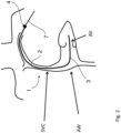
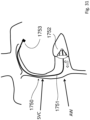
- a percutaneous heart valve treatment device 1 is shown at a general level.
- the device 1 comprises a first sheath 2 with a distal end 3 which is deformable because it has a pulley system within its core which flexes and extends the distal end of the sheath by rotation of the proximal handle.
- a proximal handle 4 comprising a haemostatic valve through which the guide wire passes, is used by the surgeon to route the first sheath 2 along the superior or inferior vena cava (SVC).
- SVC superior or inferior vena cava
- the sheath distal end 3 crosses the tricuspid or mitral AV valve ("AV") and into the right or left ventricle as illustrated.
- the guide wire is removed and the sheath is orientated towards the ventricular wall below the level of the defect in the AV valve.
- Figs. 1 to 6 show the AV valve denoted "AV”, and the atrial wall as "AW".
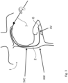
- a wire anchor 7 is then delivered ( Fig. 2 ) through the first sheath 2 to the ventricle. This is an elongate anchor which is left in situ after the procedure ( Fig. 15 )
- rotation of the guide wire anchor 7 delivers an anchor element in the form of a screw 6 to the ventricular wall.
- Rotation of the anchor 7 causes the anchor element screw 6 to penetrate and lodge in the ventricular wall. This fixes the elongate anchor 7 in place at the distal end, where it will remain after surgery.
- the anchor 7 can now be used during surgery for valve delivery and optimum positioning, and subsequently for valve support after surgery.
- the first (anchor delivery) sheath 2 is removed.
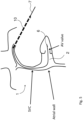
- a second, device delivery, sheath 10 is then fed in ( Fig. 5 ) using the guide wire anchor 7.
- the sheath is pulled back ( Fig. 6 ) to deploy a prosthetic valve 15. This deployment, as described in more detail below, is at an optimum longitudinal position on the anchor 7.
- the anchor 7 may for example be akin to the Biosense Webstar EZ TM steer catheter.
- the catheter delivery sheath may for example be the Medtronic TM Attain Deflectable catheter delivery system.
- first sheath 2 may be left in situ and used as the delivery sheath or support for the prosthetic valve 15.
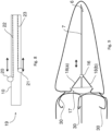
- the valve element is a prosthetic valve 15 which comprises a coupler 16 of Nitonol which locks onto the guide wire anchor 7 upon release from the delivery sheath 10, due to its shape-memory characteristic in which the Nitonol reassuming the tighter shape in body temperature to lock down on the anchor.
- the valve 15 also comprises leaflets 17 of bovine or porcine pericardium or other material connected to the coupler 16 by chords 18. As shown, the coupler 16 is slidable and lockable on the guide wire anchor 7 under control of an actuator so that the valve area encompassed by the leaflets 17 can be changed.
- Nitonol stainless steel or other suitable biocompatible material may be used.
- Fig. 8 shows the actuator, 19, at the proximal end of the second sheath (catheter).
- knobs 20 and 21 which are slidable on the sheath to axially move control cables 22 and 23. This alters the distance between the valve leaflets and the chord support coupler 16.
- Fig. 9 shows the effect of operation of the actuator 20/21 for X (axial) adjustment.
- a second coupler in the form of Nitonol prongs 30 at the level of the valve.
- the adjustable axial supports move the valve 17 and coupler in the X and Y axes. They are lockable within the anchor support as the Nitonol within the support changes shape within the anchor 7 to lock the support in place.
- a proximal collet arrangement may be used.
- the coupler 16 is of Nitonol or stainless steel and there is a similar coupler, 50, for the leaflets 17 at the opposite (distal) end of the valve 15.
- the coupler 16 is a spring maintained in an expanded state by the second sheath 10, withdrawal of which causes it to contract onto the guide wire 7 when the valve is in the correct position.
- Each coupler is held open by the sheath/tube and pulling back the sheath allows the coupler to lock down on the anchor.
- the inner tube is pulled back much the same way as a Nitonol stent or valve is delivered, however instead of expanding to fill an orifice it contracts down on the anchor.
- Fig. 12 also shows a coupler 60 transitioning between the contracted and expanded positions.
- Valve delivery is also shown in Fig. 13 , withdrawal of the delivery sheath 10 causing the coupler 16 to contract from a position supported by a tube with in the sheath onto the anchor 7.
- the axial position of the leaflet coupler 16 can be chosen and adjusted for optimum effectiveness of the prosthetic valve. This is determined by observing when regurgitation is maximally reduced.
- the valve is delivered out of the sheath first and the ideal position along the anchor identified, in examples of the disclosure not forming part of the invention then the fixation devices or couplers are released, first the distal and the then the proximal or vice versa.
- one or more stylets or collars 70 can be introduced along the guide wire anchor 7 to change shape of the device in the atrium.
- These stylets or collars are shapeable and are inserted through the core or outside of the guide wire anchor to change the orientation of the anchor and support it against the atrial or vessel wall.
- a collar may be sized to fit around the anchor and slide along the anchor to support the valve against the force of the valve regurgitation.
- the collar may in examples of the disclosure not forming part of the invention, be sutured to the subcutaneous tissue around the anchor to maintain its position, similar to collars used to fix pacemaker leads to the subcutaneous tissues as would be understood by a person skilled in the art..
- the atrial shape of the anchor can be altered by shapeable stylets or collars 70 that are inserted into the inner core or outside of the anchor guide wire.
- This provides an additional support for the anchor 7 and the prosthetic valve 15, in some cases avoiding need for the anchor to fix to heart tissue.
- the stiffness of the anchor and the foundation provided by the atrium wall provide the necessary resistance to the forces applied to the valve element from the ventricular side.
- the proximal end of the guide wire anchor 7 is sutured along a suture line 5 to subcutaneous tissue to prevent migration and to allow re-access to the prosthetic valve 15. This allows repeated access to the device to move or remove the valve 15.
- an alternative device, 100 has a valve element 101 with coupler 102 which is radially expandable in addition to being axially moveable on the guide wire anchor 7. There is also a coupler 103 at the other end of the device 100. The length and width of the coupler 102 can be varied by movement of knobs 105 on the proximal end. When width is correct, this is locked in position.
- Fig. 17 shows a device 200 having a distal coupler 201, from which extend chords 202 to a valve treatment element 203 connected to the anchor by a proximal coupler 204.
- a mechanism 210 to vary length of chords 202.
- An actuator of the mechanism 210 at the proximal end of the catheter is rotated or moved to lengthen or shorten the chords 202.
- the rotation/movement of the actuator knobs 211 and 212 varies length of the chords by virtue of cables/wires within the elongate anchor.
- the chords are attached to the chordal support on the anchor 7 which can be locked down onto the anchor similar to locking the valve.
- a valve element may be delivered and fixed to a wire/lead anchor.
- the valve element may be a prosthetic valve of the "parachute" type supported by chords that are adjustable.
- the support frame of the chords may be adjustable and fixable.
- the chords in examples of the disclosure not forming part of the invention, may be fixed to the wall of the heart.
- the atrial configuration of the anchor may be adjustable and can be fixed through the delivery of stiff wire stylets or collars.
- the valve can be made as leaflets or a deformable material that deforms due to the pressure in the ventricle to form the valve support.
- Fig. 18 shows in a device 220 altering of the position and configuration of a chordal support coupler 221, in which the coupler 221 expands radially.
- the coupler 221 is made of preformed Nitonol and takes up a curved shape as it exits the catheter, sliding knobs on the proximal end of the catheter delivers more of the Nitonol support from the distal end thus changing the position of the chordal support and
- Fig. 19 shows an actuator 225 having knobs 226 and 226 which are slid to alter the distance between the chordal support and the coupler. The extent of variation is shown in Fig. 20 by the interrupted lines.
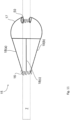
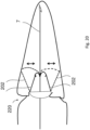
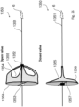
- Figs. 21(a) and 21(b) show a valve element 235 in the closed and open positions.
- Valve leaflets 240 are supported on the proximal end on an atrial ring 241 and at the distal end they form an apex where they are supported on the anchor by a coupler 243.
- the valve element 235 opens through the centre.
- Chords 242 are attached to the chordal support (or "coupler") 243 but the leaflets 240 are attached in the alternate fashion so that the blood flows through the centre of the valve next to the anchor 241.
- the bases of the prosthetic leaflets 240 are attached to the Nitonol support that sits on the atrial side of the AV valve.
- the ventricle contracts blood flow and the change in pressure in the ventricle causes the leaflets 240 to close against each other and the native heart leaflets co-apt against/on the prosthetic leaflets 240.
- the heart relaxes the pressure drops in the ventricle below the pressure in the atrium and the valve leaflets 240 open to allow blood flow into the ventricle.
- the ring holds and supports the leaflets on the atrial side on the valve. It is flexible in that it is Nitonol and can be compressed into a delivery catheter for delivery and then returns to its ring-like shape post-insertion.
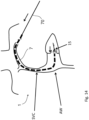
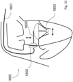
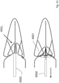
- Fig. 22 shows a view from the left atrium into the ventricle a valve 900 having leaflets 901 and 902 which are shaped to match the shape of the native valve leaflets NL (also shown for illustration purposes).
- a valve support 904 is shown.
- the perimeter of the valve is defined by a Nitonol ring 903 which may for example, reside on the atrial side of the valve and may be sized to the line of insertion of the native valve leaflets in the atrium.
- the leaflets 901 of the implantable valve are shaped to match the shape of the native valve leaflets.
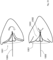
- a support has an anchor 1000, ring 1001, and a ball and socket joint distal coupler 1002.
- This allows the valve leaflets 1003 to rotate and pivot to follow the movement of the heart, and the valve 1001 is only connected to the support at the distal end.
- the support anchor 1000 has a stiffness such that the valve 1003 may be moved to fit the shape of the native valve structure, by rotation of the support anchor 1000.
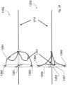
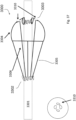
- Fig. 24 shows a configuration of valve, 1100, having a Nitonol atrial ring 1102 supporting leaflets 1101 moved by chords 1103 attached to a ring Nitonol support with support posts 1104 which extend into the ventricular side of the valve.
- leaflets 1101 are shaped and sized to match the native leaflets.
- the two lower diagrams are views from the ventricle of the open and closed valve.
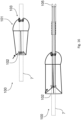
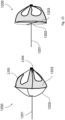
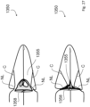
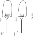
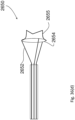
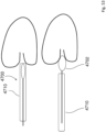
- Fig. 25 shows a valve in the open configuration 1200 having a wire support 1201 at the distal end of which there are Nitonol supports 1202 which extend radially and distally to their ends which are attached to a support ring 1203 (also of Nitonol).
- the valve leaflets are attached at their base to the Nitonol ring 1203.
- the apex of the leaflets are attached to the coupler on the anchor 1204.
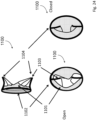
- Figs. 26 to 28 show a device 1350 having an anchor 1351, a distal coupler 1352, a proximal coupler 1353, chords 1354, and leaflets 1355 with the leaflets fixed at their base to the Nitonol or an inflatable ring 1358.
- the ring 1358 may be supported by one or more struts 1357 which attach to the anchor via the proximal coupler or may be attached to the distal coupler 1352 by a Nitonol struts.
- the support 1353, 1357, and 1358 provides support for the device in use in addition to or instead of the fixation device at the distal end of the anchor, in a manner not within the scope of the claims.
- the support 1353/1357/1358 and the leaflets 1355 are sewn or glued to the ring 1358 and the chords are tied or sewn or clamped or glued onto the chordal support 1352.
- the chords may be integral parts of the material used to form the leaflets and the leaflets are cut in such a way as to from the chordal supports attached to the chords 1354.
- the leaflets 1355 are hook-shaped, extending at their ends distally and radially. This provides more surface area to prevent regurgitation with less assistance from co-apting native leaflets, which may be badly damaged.
- the native leaflets NL native chords C also shown
- the top diagram shows the valve open, while the bottom diagram shows it closed.
- Fig. 28 shows a device 1359, in which like parts are indicated by the same reference numerals, and in which there are spring-loaded clamps 1360 on radial arms or spokes 1361.
- Fig. 29 shows a device 1600 with an outer skirt 1605 attached to an atrial ring to prevent regurgitation between the native leaflets and the valve. Otherwise, the arrangement of the valve leaflet sand their chords is as described above.
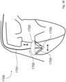
- a device 1700 comprises an elongate wire anchor 1701 supporting at its distal end a prosthetic valve 1702.
- the valve 1702 has a parachute-shaped valve member 1702 linked by chords 1704 to a coupler 1705 on the anchor 1701.
- the anchor 1701 does not need, for some uses at least, to be fixed to the heart wall by a fixing element. Instead, anchoring support is provided by stiffness of the anchor 1701.
- the anchor 1701 rests against, for example, posterior atrial tissue (atrial wall, AW) or the inter-atrial septum.
- a device 1750 also has an anchor 1751 which does not need a fixing element, supporting a prosthetic valve 1752.
- an anchor 1751 which does not need a fixing element, supporting a prosthetic valve 1752.
- a sub-cutaneous motorized controller 1753 which can deflect the positions of the anchor 1751 and the valve 1752 post implantation.
- a device 1800 also has an anchor 1801 which does not need a fixing element.
- the support element 1802 is akin to an ASD closure device with a central aperture through which the support passes.
- the anchor 1801 at the distal end 1805 bends through 90° in a variable manner so that the positions of the valve (1803) can be changed.
- the shape of the distal segment of the support is variable so that the position of the valve can be changed. Once in the correct position the shape of the support is lockable
- Fig. 33 shows leaflet supports 2300 and 2350.
- the support 2300 has a ring and posts extending from the ring across the AV valve into the ventricle.
- the support 2350 has a ring and an arch extending across the ring and into the ventricle.
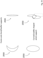
- a leaflet support 2400 for a valve has only a ring.
- a support 2450 has a ring 2451 and member 2452 connected at diametrically opposed sides of the ring 2451 extending into the ventricle with a shape of the AV valve co-apting line.
- This is a Nitonol atrial ring to which the leaflets are sewn.
- Fig. 35 shows alternative supports 2500 and 2550.
- the support 2500 is crescent (saddle) shaped in en face view, whereas the support 2550 is oval in en face view.
- Fig. 36(a) shows a supports 2600 having a ring 2601 and valve leaflets 2603 are sewn to posts 2602 extending across the valve. This is a ring member and two post supports to which the leaflets are attached.
- Figs. 36(b) to 36(e) show a device 2650, similar to the device in Fig. 36 (a) having an elongate anchor 2651 with proximal-end actuators. At the distal end there is an atrium support ring 2652 linked by Nitonol supports 2653 to a distal actuator 2654. There are also axial support arms 2655 which in use extend across the valve and support leaflets 2656.
- Actuators are connected via wires to the atrial support ring of the valve.
- Fig. 36(c) shows the open and closed valve with native leaflets co-apting on the valve leaflets.
- Fig. 36(d) shows a magnified view of the support cables for an atrial ring of the valve running the length of the support.
- FIG. 36(e) there is an outer deflectable support sheath 2657.
- This diagram also shows an inner support tube can rotate within outer deflectable support sheath. The valve is rotated to align with the commissures of the native valve.
- a device 3300 has an anchor 3301, Nitonol couplers 3302 and 3303, valve leaflets 3304, and chords 3305. There are also secondary chords 3306 extending from the distal coupler 3302 to the proximal sides of the leaflets 3304.
- the leaflets 3304 have fenestrations 3310 arranged around the axis close to the coupler 3303. The fenestrations 3310 allow washing jets as the pressure in the ventricle rises and the valve closes causing blood flow from the high pressure ventricular side of the valve to the lower pressure atrial side of the valve, ensuring small amounts of blood flow at the base of the valve to prevent clot formation.
- Fig. 37 includes, on the bottom left, a view of the valve from the atrium, showing the fenestrations 3310 more clearly.
- chords 4001 in a device 4000 rotation of the knobs causes chords 4001 to be fixed to the wall of the heart by way of fixation devices at the ends.
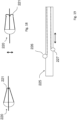
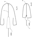
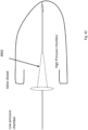
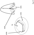
- Figs. 39 and 40 show a valve element 4050. It has a native state shown in Fig. 39 which is frustoconical with the narrow end facing into the chamber, and has a resilience such that when pressure rises in the chamber it narrows to a point facing into the chamber and the larger outer end seals the chamber as shown in Fig. 40 .
- Figs. 41 and 42 show a valve element 4060 in which the element has an elastic shape which conforms to the shape of the orifice under high pressure and returns to its native state under chamber low pressure conditions.
- the overall shape is T-shaped in cross-section, with a discshaped head outside and a stem inside.
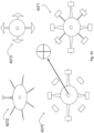
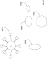
- Figs. 43 and 44 are diagrams showing various alternative configurations 4071, 4072, 4073, 4074 of material cuts during manufacture to suit the nature of the valve defect.
- the valve and chords may be made from a single piece of pericardium or other suitable biocompatible material, or alternatively suture material or the like may be sewn into the leaflets to form the chords.
- the shapes in end view may have 4, 8 or any desired number of arms, and the leaflets may have any desired configuration of end shape at the radial outer position.
- the central part, for engaging the native valve leaflets may have a round, oval (4080, 4081, 4082), or polygonal (4083) shape when viewed in the axial direction.
- Fig. 45 shows a view from within the ventricle in use, of a device with an anchor coupler 4351 and chords 4352 from the coupler 4351 to an atrial ring 4354.
- This support arrangement effectively clamps on both sides of the native valve, the arms and clamps 4360 on the V side and the ring on the A side.
- An alternative is also shown, namely a Nitonol hook 4380 not within the scope of the claims, on the ventricular side of the AV valve.
- Within the delivery catheter there are two smaller sheaths that maintain the Nitonol clamps in an open state. When the clamps are in the correct positions the sheaths are pulled back to release the Nitonol to engage the heart tissue.
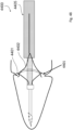
- Figs. 46 and 47 show Nitonol supports 4390 for engagement on the LV side of the valve.
- the supports 4390 are Y-shaped, with two radially distal branches for engaging within the tissue not within the scope of the claims. They extend from a ring 4391 on the atrium side in use.
- Fig. 47 is a ventricle-side view.
- Fig. 48 shows delivery of a device 4400 with clamp/hook like valve supports to AV groove.
- Hooks 4401 being delivered in a compressed state in a delivery catheter 4405.
- Chords 4402 are shown.
- the hooks 4401 or spring-loaded clamps are delivered in a compressed state in delivery of the catheter and are released/positioned in the commissures of the valve at the AV groove.
- Fig. 49 shows a device 4410 having hook-like supports 4411 at the ends of chords 4412.
- the Nitonol supports 4411 are attached to chordal supports on the LV side of the AV groove
- Figs. 50 and 51 show delivery of a device 4500 with spring-loaded wing-like supports 4501. These engage the LV side of the annulus. Nitonol wings 4503 are attached to the chordal supports 4501 and are delivered by pulling back the sheath 4502.
- a device 4700 has an elongate anchor 4701 and a valve element 4702 comprising a Nitonol frame 4703 covered by a cover 4704.
- the cover may be of any biocompatible material such as pericardium.
- the shape is to allow the native valve leaflets to co-apt against it.
- the device is delivered by a catheter 4710, in which retraction of the delivery sheath allows the valve element to expand.
- Nitonol springs are released to clamp the device at this position.
- Fig. 55 shows an alternative arrangement of parachute valve 4800 without leaflet chords.
- Leaflets 4801 are cup-shaped and are sewn or glued directly to a Nitonol support frame 4804 which attaches to an anchor 4803.
- valve support of the device has one or more of the following features.
- the valve may have one or more of the following features.
- the invention achieves a percutaneously-delivered valve made up of one or more leaflets, which can be made from porcine or bovine pericardium or other materials, which is attached to an anchor by one or more supports either on a ring on the atrial side of the native valve or directly to the anchor.
- the stiffness of the anchor resists the force pushing the valve into the atrium and maintains the valve in the desired position.
- leaflets may be supported by chords which can be varied in length and position and may also in examples of the disclosure not forming part of the invention be fixed to the wall of the heart.
- the valve may be supported not within the scope of the claims, by an anchor which is fixed to the wall of the heart.
- the valve may be supported by a portion of the anchor against the atrial wall, due to stiffness of the anchor. This can be re-enforced by the use of stylets or collars within or around the anchor.
- the valve may be additionally or alternatively be supported by struts or hooks on the LV (distal) side of the valve.
- the device has fenestrations it allows blood flow back into the atrium. This is a very simple and effective mechanism to prevent clot formation.
- leaflets and chords may be attached to a single elongate support that attaches to the anchor.
- the distance between the leaflets and chords is fixed and there are different sizes of device that are implanted depending on the size of defect in the valve.
- a support from the atrial or interatrial wall which supports the valve (and possibly also an anchor) and prevents it prolapsing back into the atrium.
- the support is delivered over the anchor to rest against the posterior atrial wall.
- the support may be hollow and fit around the anchor or the valve maybe attached to the distal end of the support.
- the distal end of the support is deflectable by means of a mechanism such as a pulley system within its core that alters the tension in elements within its wall.
- the shape of the distal end of the support may be lockable.
- the support may abut against the coupler of the valve attached to the anchor.
- the support has an inherent stiffness that serves to maintain the valve in the desired position. For a support for the left sided AV valve there will be a fixed angle bend in the support as it crosses the interatrial septum and the distal end of the support is deflectable as well.
- arms to position the valve in the superior/inferior axis can be fed through to rest against the posterior atrial wall to support the valve.
- any part of the device may be of a material which is visible to equipment such as echo or X-ray imaging equipment.
- the prosthetic valve adaptation may not be under user control, even where it has leaflets. For example pressure differential may be availed of to cause adaptation of the leaflets to suit the nature of the defect in the heart valve.
- the device may further comprise a controller arranged to be implanted sub-cutaneously on the supports to allow the position of the valve element and the couplers to be changed after insertion. Electromagnetic switches may be used to activate motors which increase the tension in the wires within the wall of the support to alter the shape/position of the distal end of the anchor/support.
Landscapes
- Health & Medical Sciences (AREA)
- Cardiology (AREA)
- Engineering & Computer Science (AREA)
- Biomedical Technology (AREA)
- Heart & Thoracic Surgery (AREA)
- Transplantation (AREA)
- Oral & Maxillofacial Surgery (AREA)
- Vascular Medicine (AREA)
- Life Sciences & Earth Sciences (AREA)
- Animal Behavior & Ethology (AREA)
- General Health & Medical Sciences (AREA)
- Public Health (AREA)
- Veterinary Medicine (AREA)
- Prostheses (AREA)
Description
- The invention relates to surgical devices, specifically for treating the heart.
- In particular the invention relates to treating leaking heart valves, such as the atrioventricular (AV) valves.
- The heart contains four valves, two semilunar, the aortic and pulmonary valves, and two AV valves, the mitral and tricuspid valves. The heart fills with blood from the lungs and body when the AV valves are open. When the heart pumps or contracts, the AV valves close and prevent the blood from regurgitating backwards. The semilunar valves open when the heart pumps allowing the blood to flow into the aorta and main pulmonary artery.
- Dysfunction of the cardiac AV valves is common and can have profound clinical consequences. Failure of the AV valves to prevent regurgitation leads to an increase in the pressure of blood in the lungs or liver and reduces forward blood flow. Valvular dysfunction either results from a defect in the valve leaflet or supporting structure, or dilation of the fibrous ring supporting the valve. These factors lead to a failure of valve leaflets to meet one another, known as co-aptation, allowing the blood to travel in the wrong direction.
- Conventional treatment of leaking AV valves often involves replacement or operative repair of the valves. These treatments are considerable surgical operations requiring cardiopulmonary bypass and are associated with significant morbidity. In many instances patients are too sick or too frail to undergo these operations and hospital stays and recovery phases after such operations are prolonged.
- Percutaneous techniques of valve repair have the advantage of being significantly less traumatic for the patient. During such procedures the valve repair is performed from within the heart, accessing the heart through a vein in the neck or the groin. Percutaneous procedures are performed under local anaesthetic and the incisions required to perform the procedures are extremely small. In addition, procedural times and recovery phases are also expected to be significantly less. Current attempts at percutaneous repair of leaking heart valves include insertion of a mitral valve support structure into a large cardiac vein known as the coronary sinus. Another is insertion of a stitch or clip into the mitral valve leaflets to hold them together. Another is insertion of a new prosthetic valve percutaneously.
-
WO2006/064490 (Mednua ) describes a device with a generally cylindrical treatment element for location between a pair of valve leaflets. The device occludes the valve opening to resist retrograde flow. A tether extends into the ventricle and is connected to an anchor engaging the ventricle wall to support the device. -
WO2007/144865 (Mednua ) also describes a device for treatment of a mitral valve, located in the region of co-aptation of the native leaflets. An anchor element anchors the device to the ventricle wall at the apex of the ventricle. -
WO2009/053952 (Mednua ) describes a percutaneous approach in which a treatment element is located between a pair of valve leaflets. A support has an anchor with for example a screw for engaging heart wall tissue. The treatment element comprises a hydrogel. -
US2013/0090728 andWO2006/111391 (Edwards Lifesciences AG ) describe an approach in which a mitral valve flow improvement device is percutaneously inserted. It has a prosthetic mitral valve leaflet, and a tissue-penetrating anchor. Blood flow from the left ventricle to the left atrium expands the prosthetic leaflet into the closed state so that it is umbrella-shaped. Support for the device is provided by either a stent-like support or by anchors which engage tissue within the heart. -
US2013/0325110 (Edwards Lifesciences Corp. ) describes devices for improving the functioning of a defective heart valve. A locking mechanism locks position of a co-apting element within the tricuspid valve (TV) and relative to a fixed anchor rail. The locking mechanism is a collet mechanism which locks a catheter onto the anchor rail, which runs through the catheter. The catheter and rail exit the subclavian vein (SV) at a puncture and remain implanted. The locking mechanism remains external, on a coil of the catheter/rail. An alternative arrangement is crimping the catheter onto the rail near the entry point. -
US2013/0338763 (Edwards Lifesciences ) also describes a heart valve co-aptation system with a locking collet. It also discloses anchoring of the co-aptation element using stent structures which straddle the tricuspid valve. -
WO2008/141322 (Cardiosolutions ) discloses a heart valve implant on an anchor to engage tissue.EP2032080 (Edwards Lifesciences ) discloses a device and methods for improving the function of a heart valve.US6332893 (Mortier Todd ) discloses a device for heart valve repair including at least one tension member.WO2005/087140 (Percutaneous Cardiovascular ) describes a percutaneous heart valve prosthesis that has a valve body with a passage extending between the first and second ends of the valve body. - The invention is directed towards providing an improved heart valve treatment device for percutaneous delivery.
- According to the invention, there is provided a heart valve therapeutic device as set out in
claim 1. Features of the disclosed device are set out in appendedclaims 2 to 14. - Preferably, the device comprises a stylet or a shaped or stiff collar arranged to provide a desired shape to the anchor.
- In one embodiment, the actuator comprises control cables which are arranged to be moved axially under surgeon control.
- In one embodiment, the device comprises an adjustment mechanism for varying individual chords connecting at least one coupler to the prosthetic valve element, and wherein the mechanism is arranged to shorten one or more chords and lengthen one or more other chord. Preferably, the device comprises at least two couplers supporting the valve element on the anchor and the actuator is configured to set mutual separation of the couplers for configuration of the valve element.
- Preferably, the actuator comprises a mechanism which shortens or lengthens linking of a support ring to the anchor, for tilting of the valve element. Preferably, said ring is configured to engage atrium tissue and the valve element further comprises arms extending distally and axially.
- In one embodiment, the device comprises an adjustment mechanism for varying said chords to adjust angle of the valve element with respect to the axis of the elongate anchor
- In one embodiment, the valve element comprises prosthetic leaflets shaped for co-apting with native leaflets, and said prosthetic leaflets have together a smaller radial dimension for at least some of their length when the native leaflets are closed and a larger radial dimension when the native leaflets are open. Preferably, the valve element comprises prosthetic valve leaflets that are supported to extend axially and radially outwardly towards the proximal end, with an apex facing into a heart chamber in use. In one embodiment, the prosthetic valve leaflets are supported at their proximal end on a ring.
- In one embodiment, the prosthetic valve leaflets are arranged so that in use blood flows through the centre of the valve.
- In one embodiment, the support includes a radial support part which is radially distant from the anchor and is configured to engage atrial tissue on a proximal side of a valve. Preferably, the radial support part comprises a ring extending around a device axis. In one embodiment, the ring is on spokes.
- In one embodiment, the ring is connected to chords extending from a coupler on an anchor.
- In one embodiment, the ring comprises a proximal skirt arranged to prevent regurgitation between the native leaflets and the valve element. In one embodiment, said skirt comprises a rim of material. In one embodiment, said rim is of material which is the same material as material of valve element leaflets sewn or glued to a distal side of the radial support.
- In one embodiment, the anchor is configured to rest against a posterior atrial wall upon deployment.
- In one embodiment, the distal end of the support is deflectable such that position of the support can be altered to position the valve element to provide maximum reduction in regurgitation, the device comprising a mechanism for altering tension in elements within the support.
- In one embodiment, the radial support abuts against a coupler of the valve attached to the anchor.
- In one embodiment, the actuator further comprises a controller arranged to be implanted subcutaneously on the anchor to allow the position of the valve element to be changed after insertion.
- In one embodiment, the device comprises an element for clamping the anchor to a wall through which the anchor passes.
- In one embodiment, the valve element comprises leaflets shaped like native leaflets and having a ring-shaped support around its circumference.
- In one embodiment, the valve element is connected to the anchor by a coupler so that rotation of the support moves the valve to fit to the shape of the native valve.
- In one embodiment, the support comprises a ring and one or more members extending distally such that they cross an AV valve in use, said members including a member interconnecting opposed side of the ring.
- In one embodiment, the support includes a ring which is circular or oval or crescent-shaped.
- In one embodiment, the device further comprises a sheath for delivering the anchor.
- In one embodiment, the valve element comprises at least one fenestration configured to, in use, provide central flow such as washing jets to prevent or reduce thrombosis, wherein the fenestrations are at or adjacent to the base of the prosthetic valve element.
- In one embodiment, there are a plurality of fenestrations arranged circumferentially around a valve element axis, and wherein the fenestrations each have a cross-sectional area in the range of 0.5 mm2 to 3 mm2, and they may have any suitable shape to suit the available areas such as circular, triangular, square or slit-like.
- In one embodiment, the valve element comprises leaflets which are cup-shaped and are secured directly to a support frame which attaches to the anchor.
- In another aspect, the invention provides a heart valve therapeutic kit comprising a plurality of devices as defined above in any embodiment, at least some of which are of different sizes to suit different sizes of patient valve defects.
- In another aspect, the invention provides a pacemaker comprising a device as defined above in any embodiment and pacemaker electrodes mounted on the anchor at a distal end of the anchor.
- In one embodiment, the actuator is at a proximal end of the device. In one embodiment, the prosthetic valve comprises a proximal coupler, and leaflets connected to the coupler by chords. Preferably, the prosthetic valve comprises proximal and distal couplers connecting the valve to the elongate anchor. In one embodiment, the actuator comprises control cables which are arranged to be moved axially under surgeon control.
- In one embodiment, the device comprises an adjustment mechanism for varying individual chords connecting at least one coupler to the prosthetic valve leaflets. In one embodiment, the mechanism is arranged to shorten one or more chords while lengthening one or more other chords or chords. In one embodiment, the actuator comprises a rotating mechanism which shortens or lengthens chords upon rotation of one or more actuator device in a selected direction. In one embodiment, the chords are attached to a coupler within the anchor which can be locked down onto the anchor.
- In one embodiment, the device comprises an adjustment mechanism for varying said chords to adjust angle of the leaflets with respect to the axis of the elongate anchor.
- In one embodiment, the prosthetic valve comprises valve leaflets that are supported to extend axially and radially outwardly towards the proximal end, with an apex facing into a heart chamber in use. In one embodiment, the leaflets are supported at their proximal end on a ring. In one embodiment, the leaflets are arranged so that in use blood flows through the centre of the valve.
- In one embodiment, the device comprises a stylet arranged to be introduced by sliding along the anchor to provide a desired shape at the prosthetic valve.
- In one embodiment, the prosthetic valve comprises a deformable element which is adapted to deform to seal the chamber. Preferably, the deformable element is adapted to deform under heart chamber pressure. In one embodiment, the device comprises an actuator for assisting or solely causing deformation of the deformable element.
- In one embodiment, the deformable element comprises a stem which is configured to extend into a heart chamber, and a head which remains outside, the stem decreasing in volume and expanding the head during chamber higher pressure.
- In one embodiment, the prosthetic valve comprises at least one fenestration configured to, in use, provide central flow such as washing jets to prevent or reduce thrombosis. In one embodiment, the fenestrations are at or adjacent to the base of the prosthetic valve.
- In one embodiment, there are a plurality of fenestrations arranged circumferentially around a device axis.
- In one embodiment, the fenestrations each have a cross-sectional area in the range of 0.5 mm2 to 3 mm2, and they may have any suitable shape to suit the available areas such as circular, triangular, square or slit-like.
- In one embodiment, the device comprises a support at least part of which is radially distant from the anchor and is configured to engage tissue. In one embodiment, the support comprises a ring extending around the device axis. In one embodiment, the ring is on spokes.
- In one embodiment, the support is arranged to be delivered over an anchor to rest against the posterior atrial wall.
- In one embodiment, the support abuts against a coupler of the valve attached to the anchor.
- In another aspect, the invention provides a heart valve therapeutic kit comprising a plurality of devices as described above in any embodiment, at least some of which are of different sizes to suit different sizes of patient valve defects.
- In various embodiments we describe a percutaneously-delivered valve made up of one or more leaflets, which can be made from porcine or bovine pericardium or other materials, which is attached to an anchor by one or more supports either on a ring on the atrial side of the native valve or directly to the anchor. The valve may be supported by the proximal portion of the anchor against the atrial wall. This can be re-enforced by the use of stylets within the anchor. The valve may be additionally or alternatively be supported by struts or hooks on the LV (distal) side of the valve. There may be a compressive force between these and the atrial ring or they may rest against the AV groove to resist the valve moving back into the atrium. Such a support may do away with the need for the anchor and the anchor could be removed at the end of the case. In some embodiments of the device there may be fenestrations at the base of the valve to allow a small amount of blood flow back into the atrium to prevent clot formation.
- In one embodiment, the anchor has a variable shape.
- In one embodiment, the device further comprises a controller arranged to be implanted subcutaneously on the supports.
- In one embodiment, the support comprises an element for clamping the support to a wall through which it passes.
- In one embodiment, the valve comprises leaflets shaped like native leaflets and having a ring-shaped support around its circumference.
- In one embodiment, the valve is only supported in a support in the form of a wire, whereby rotation of the support moves the valve to fit to the shape of the native valve structure.
- In one embodiment, the support comprises a wire and a plurality of support members extending distally and radially from a location at or near a distal end of the wire.
- In one embodiment, the support comprises a ring and one or more members extending distally such that cross an AV valve in use.
- In one embodiment, said members include a member interconnecting opposed side of the ring.
- In one embodiment, the support includes a ring which is circular or oval or crescent-shaped.
- The invention will be more clearly understood from the following description of some embodiments thereof, given by way of example only with reference to the accompanying drawings, in which aspects not within the scope of the claims are indicated as such in the detailed description which follows, and in which:-
-
Figs. 1 to 6 are a series of diagrams illustrating deployment of a device of the invention to treat a patient's AV valve; -
Figs. 7(a) and 7(b) are diagrams illustrating adjustment of a prosthetic valve of the device when deployed; -
Fig. 8 is a diagram showing an actuator at a proximal end of the device; -
Figs. 9 and10 are diagrams illustrating differential adjustment of the prosthetic valve to provide a non-symmetrical configuration to suit the clinical situation; -
Fig. 11 shows a specific example of the fixing devices of the treatment device andFig. 12 is a pair of diagrams illustrating a principle of operation of couplers on the anchor, andFig. 13 shows the mechanism in more detail; -
Fig. 14 is a diagram showing addition of stylets to achieve a desired shape in the atrium; -
Fig. 15 shows suturing of the anchor guide wire at the proximal end; -
Fig. 16 is a pair of diagrams showing a treatment device with a chordal support with adjustable width; -
Fig. 17 is a pair of diagrams showing a treatment device of another embodiment with chordal length adjustment; and -
Fig. 18 is a diagram showing altering the position of chordal supports, andFig. 19 is a diagram showing a user actuator for this altering; -
Fig. 20 is a diagram showing adjustment of chordal supports; - Figs. 21(1) and
21(b) are diagrams showing an alternative prosthetic valve in which leaflets extend proximally and radially from a distal coupler for optimum co-aptation; -
Fig. 22 shows another valve element with leaflets shaped to match the native leaflets and the orifice; -
Fig. 23 is a pair of diagrams showing a valve element which can change orientation about a distal apex at which the anchor is terminated; -
Fig. 24 is a set of diagrams showing alternative valve element leaflets; -
Fig. 25 is a pair of diagrams showing a valve element having Nitonol or steel supports attached to a ring for engagement in the atrium side; -
Figs. 26 to 29 show devices which are variations of the device ofFig. 25 , in open and closed positions, in which:-
Fig. 26 is a pair of views of a device with a prosthetic valve in open and closed states, the valve having a support ring attached centrally to the anchor and the ring being arranged for engaging surrounding tissue for additional device support; -
Fig. 27 shows this device in situ with the support engaging tissue on the atrium side and native leaflets co-apting against the prosthetic valve leaflets; -
Fig. 28 is a pair of views of an alternative device in the open and closed positions, in which there is also a ring-shaped support and additionally this support has spring-loaded clamps on diametrically opposed sides of the ring, this being one example of fixation elements on the ring, alternatives being hooks or barbs; and -
Fig. 29 shows a device with an outer skirt attached to an atrial ring to prevent regurgitation;
-
-
Fig. 30 shows another device having a wire anchor without a fixing element, the anchor being stiff and adjustable; -
Fig. 31 shows a device which has a sub-cutaneous controller; -
Fig. 32 shows a device in which a wire anchor has a variable distal end to change position of its prosthetic valve; -
Fig. 33 is a set of views showing two valve elements, each having parts extending from a ring across the AV valve into the ventricle; -
Fig. 34 shows further valve elements with atrium-side support rings, andFigs. 35 and36 show further support shapes; -
Fig. 37 is a side view diagram showing a device with fenestrations for allowing flow at the base of the leaflets and so help to prevent clot formation; -
Fig. 38 is a diagram showing fixing of valve element chords to the wall of the heart; -
Fig. 39 is a diagram showing a valve open element in a native state, andFig. 40 shows forming of a valve-like structure; -
Fig. 41 shows how an elastic shape conforms to shape of an orifice to seal between low and high pressure chambers; -
Fig. 42 shows return of the elastic shape to its native shape; -
Figs. 43 and44 show some examples of shapes for various valve elements as they are cut from material during manufacture, particularly parachute-type valve elements; -
Fig. 45 is an AV enface view from the ventricle of part of the device ofFig. 28 in use, with a ring on the atrial side and showing a magnified view of a spring-loaded clamp, and a similar view of an alternative fixation device in this case a Nitonol hook configured to engage surrounding tissue on the ventricular side; -
Figs. 46 and47 are views, also from the ventricular side, showing an alternative pair of diametrically opposed fixation devices, in this case on radial arms or spokes and configured for engaging on the LV side, while a ring engages on the atrium side; -
Fig. 48 is a side view of a device being delivered by a catheter so that the fixation devices on a ring are correctly positioned at the AV groove; -
Fig. 49 is a side view of a device with fixation devices on support arms to support the device against the force of the blood being pushed back into the atrium, and thereby adding additional support to the anchor screw; -
Fig. 50 is a pair of views of a device with strut-like supports being delivered, andFig. 51 shows the supports in place; -
Fig. 52 shows a valve insert having a Nitonol frame with a skin cover, in this case of pericardium,Fig. 53 shows delivery of the valve, andFig. 54 shows details including clamping of the valve to the elongate support by way of Nitonol springs; and -
Fig. 55 shows a valve insert without chords. - A heart valve therapeutic device has a prosthetic valve insert or element which is positioned on an elongate anchor having a longitudinal axis at a desired axial position on the anchor during delivery. The valve element positioning on the anchor is set by the surgeon using an actuator at the proximal end of the anchor. The terms "valve insert" and "valve element" are used in this specification to mean the therapeutic element which is inserted into the AV area to assist the native valve leaflets or in some cases function closer to or as a full valve where the native valve is considerably damaged. In the latter case it may be referred to as a "prosthetic valve".
- In various examples of the disclosure, we describe a device with a valve insert to reduce regurgitation, that is inserted through a blood vessel on a deflectable support that may (not forming part of the invention) or may not be fixed to the heart wall. The shape and position of the valve insert and of the support can be altered and the support acts against the force pushing the valve insert back into the atrium. The valve insert is designed to allow the native leaflets to continue to move and co-apt against the surface of the valve insert.
- Stiff stylets or outer cover/catheter may be employed to stiffen the anchor to support the valve element against the heart wall or atrial septum, and this arrangement may avoid need for fixing to the heart tissue. A deflectable and/or lockable catheter with inherent stiffness may be used to maintain the valve element in position. The catheter is adjustable post-implantation through motorized controls implanted under the skin at the point of exit of the catheter from the vein.
- There may be in examples of the disclosure not forming part of the invention a part of the support which fixes to the heart tissue in the atrium, such as a ring which engages the atrium adjacent and around the AV valve. Hooks may attach to the atrial ring and support the valve from the commissures or the ventricular side of the valve. The valve element may be fixed to the distal end of the anchor, and this may be at a universal-type joint allowing it to pivot or rotate to adjust to the movement of the heart native leaflets.
- The support in several embodiments comprises an elongate anchor which extends through a blood vessel and is left in situ, being sutured in some embodiments at a proximal location such as in the shoulder area. It is supported in examples of the disclosure not forming part of the invention by engaging the heart wall such as by a barb or other fixing element at its distal end, and/or by its inherent stiffness. In the latter case the atrial or vessel wall can provide support at a bend in the anchor. A stylet or collar may be provided to slide along the anchor to provide a desired shape at the valve element and also a desired position.
- The position of the device on the anchor may in some embodiments be changed after delivery. Moreover, in some embodiments, the orientation and/or radial/longitudinal position of the valve element may be adjusted either during delivery or afterwards using controls at a proximal end of the elongate anchor.
- Advantageously, the position and orientation of the device is not fixed by the requirement to affix it directly to the heart using a tether and fixing element such as a barb or screw, this being avoided by stiffness and locking of the anchor, possibly using support from the atrium wall.
- The valve element may have any of a variety of configurations. If the defect is large it may be of the parachute type, operating like a fully-functioning valve. If the defect is not large the valve element may have leaflets or a closed body with a shape suitable for the native valve leaflets to co-apt against it. In some such embodiments, it merely prevents on-axis retrograde flow Importantly, the invention allows adjustment of axial position of the valve element, and in some embodiments orientation of the valve element on the elongate anchor. This allows the surgeon to achieve optimum position of the valve for its purpose.
- The surgeon has visibility of the position of the device during surgery by virtue of a combination of known techniques such as an echo cardiogram and X-ray equipment for visibility of metal parts of the device.
- Advantageously, the device may be incorporated in a pacemaker lead, in which case the anchor forms the elongate body of the pacemaker lead, and supports both the valve element in the AV region and the pacemaker electrodes.
- Referring to
Figs. 1 to 6 a percutaneous heartvalve treatment device 1 is shown at a general level. Thedevice 1 comprises afirst sheath 2 with adistal end 3 which is deformable because it has a pulley system within its core which flexes and extends the distal end of the sheath by rotation of the proximal handle. - A
proximal handle 4, comprising a haemostatic valve through which the guide wire passes, is used by the surgeon to route thefirst sheath 2 along the superior or inferior vena cava (SVC). At the end of the travel the sheathdistal end 3 crosses the tricuspid or mitral AV valve ("AV") and into the right or left ventricle as illustrated. The guide wire is removed and the sheath is orientated towards the ventricular wall below the level of the defect in the AV valve.Figs. 1 to 6 show the AV valve denoted "AV", and the atrial wall as "AW". - A
wire anchor 7 is then delivered (Fig. 2 ) through thefirst sheath 2 to the ventricle. This is an elongate anchor which is left in situ after the procedure (Fig. 15 ) - As shown in
Fig. 3 , in examples of the disclosure not forming part of the invention rotation of theguide wire anchor 7 delivers an anchor element in the form of ascrew 6 to the ventricular wall. Rotation of theanchor 7 causes theanchor element screw 6 to penetrate and lodge in the ventricular wall. This fixes theelongate anchor 7 in place at the distal end, where it will remain after surgery. Theanchor 7 can now be used during surgery for valve delivery and optimum positioning, and subsequently for valve support after surgery. - As shown in
Fig. 4 , in examples of the disclosure not forming part of the invention, with theanchor element screw 6 fixed to the ventricular wall the first (anchor delivery)sheath 2 is removed. A second, device delivery,sheath 10 is then fed in (Fig. 5 ) using theguide wire anchor 7. When the distal end of thesecond sheath 10 is in the ventricle the sheath is pulled back (Fig. 6 ) to deploy aprosthetic valve 15. This deployment, as described in more detail below, is at an optimum longitudinal position on theanchor 7. - The
anchor 7 may for example be akin to the Biosense Webstar EZ™ steer catheter. The catheter delivery sheath may for example be the Medtronic™ Attain Deflectable catheter delivery system. - In an alternative embodiment, the
first sheath 2 may be left in situ and used as the delivery sheath or support for theprosthetic valve 15. - Referring to
Figs. 7(a) and 7(b) the valve element is aprosthetic valve 15 which comprises acoupler 16 of Nitonol which locks onto theguide wire anchor 7 upon release from thedelivery sheath 10, due to its shape-memory characteristic in which the Nitonol reassuming the tighter shape in body temperature to lock down on the anchor. Thevalve 15 also comprisesleaflets 17 of bovine or porcine pericardium or other material connected to thecoupler 16 bychords 18. As shown, thecoupler 16 is slidable and lockable on theguide wire anchor 7 under control of an actuator so that the valve area encompassed by theleaflets 17 can be changed. Instead of Nitonol, stainless steel or other suitable biocompatible material may be used. -
Fig. 8 shows the actuator, 19, at the proximal end of the second sheath (catheter). There are twoknobs move control cables chord support coupler 16. -
Fig. 9 shows the effect of operation of theactuator 20/21 for X (axial) adjustment. There is a second coupler in the form of Nitonol prongs 30 at the level of the valve. The adjustable axial supports move thevalve 17 and coupler in the X and Y axes. They are lockable within the anchor support as the Nitonol within the support changes shape within theanchor 7 to lock the support in place. In other embodiments, a proximal collet arrangement may be used. - Also, as shown in
Fig. 10 there is movement of theanchor 7 with the valve attached in the Y direction. - Referring to
Fig. 11 thevalve 15 is shown in more detail. Thecoupler 16 is of Nitonol or stainless steel and there is a similar coupler, 50, for theleaflets 17 at the opposite (distal) end of thevalve 15. - As shown in
Fig. 12 thecoupler 16 is a spring maintained in an expanded state by thesecond sheath 10, withdrawal of which causes it to contract onto theguide wire 7 when the valve is in the correct position. Each coupler is held open by the sheath/tube and pulling back the sheath allows the coupler to lock down on the anchor. The inner tube is pulled back much the same way as a Nitonol stent or valve is delivered, however instead of expanding to fill an orifice it contracts down on the anchor.Fig. 12 also shows acoupler 60 transitioning between the contracted and expanded positions. - Valve delivery is also shown in
Fig. 13 , withdrawal of thedelivery sheath 10 causing thecoupler 16 to contract from a position supported by a tube with in the sheath onto theanchor 7. The axial position of theleaflet coupler 16 can be chosen and adjusted for optimum effectiveness of the prosthetic valve. This is determined by observing when regurgitation is maximally reduced. The valve is delivered out of the sheath first and the ideal position along the anchor identified, in examples of the disclosure not forming part of the invention then the fixation devices or couplers are released, first the distal and the then the proximal or vice versa. - Referring to
Fig. 14 , one or more stylets orcollars 70 can be introduced along theguide wire anchor 7 to change shape of the device in the atrium. These stylets or collars are shapeable and are inserted through the core or outside of the guide wire anchor to change the orientation of the anchor and support it against the atrial or vessel wall. Where a collar is used it may be sized to fit around the anchor and slide along the anchor to support the valve against the force of the valve regurgitation. The collar may in examples of the disclosure not forming part of the invention, be sutured to the subcutaneous tissue around the anchor to maintain its position, similar to collars used to fix pacemaker leads to the subcutaneous tissues as would be understood by a person skilled in the art.. Hence, the atrial shape of the anchor can be altered by shapeable stylets orcollars 70 that are inserted into the inner core or outside of the anchor guide wire. This provides an additional support for theanchor 7 and theprosthetic valve 15, in some cases avoiding need for the anchor to fix to heart tissue. In this case the stiffness of the anchor and the foundation provided by the atrium wall provide the necessary resistance to the forces applied to the valve element from the ventricular side. - Referring to
Fig. 15 , after delivery, the proximal end of theguide wire anchor 7 is sutured along asuture line 5 to subcutaneous tissue to prevent migration and to allow re-access to theprosthetic valve 15. This allows repeated access to the device to move or remove thevalve 15. - Referring to
Fig. 16 , an alternative device, 100, has avalve element 101 withcoupler 102 which is radially expandable in addition to being axially moveable on theguide wire anchor 7. There is also acoupler 103 at the other end of thedevice 100. The length and width of thecoupler 102 can be varied by movement ofknobs 105 on the proximal end. When width is correct, this is locked in position. -
Fig. 17 shows adevice 200 having adistal coupler 201, from which extendchords 202 to avalve treatment element 203 connected to the anchor by aproximal coupler 204. There is amechanism 210 to vary length ofchords 202. An actuator of themechanism 210 at the proximal end of the catheter is rotated or moved to lengthen or shorten thechords 202. The rotation/movement of the actuator knobs 211 and 212 varies length of the chords by virtue of cables/wires within the elongate anchor. The chords are attached to the chordal support on theanchor 7 which can be locked down onto the anchor similar to locking the valve. - In various embodiments a valve element may be delivered and fixed to a wire/lead anchor. The valve element may be a prosthetic valve of the "parachute" type supported by chords that are adjustable. The support frame of the chords may be adjustable and fixable. The chords in examples of the disclosure not forming part of the invention, may be fixed to the wall of the heart. The atrial configuration of the anchor may be adjustable and can be fixed through the delivery of stiff wire stylets or collars. The valve can be made as leaflets or a deformable material that deforms due to the pressure in the ventricle to form the valve support.
-
Fig. 18 shows in adevice 220 altering of the position and configuration of achordal support coupler 221, in which thecoupler 221 expands radially. Thecoupler 221 is made of preformed Nitonol and takes up a curved shape as it exits the catheter, sliding knobs on the proximal end of the catheter delivers more of the Nitonol support from the distal end thus changing the position of the chordal support andFig. 19 shows anactuator 225 havingknobs Fig. 20 by the interrupted lines. -
Figs. 21(a) and21(b) show avalve element 235 in the closed and open positions.Valve leaflets 240 are supported on the proximal end on anatrial ring 241 and at the distal end they form an apex where they are supported on the anchor by acoupler 243. Thevalve element 235 opens through the centre.Chords 242 are attached to the chordal support (or "coupler") 243 but theleaflets 240 are attached in the alternate fashion so that the blood flows through the centre of the valve next to theanchor 241. The bases of theprosthetic leaflets 240 are attached to the Nitonol support that sits on the atrial side of the AV valve. When the ventricle contracts blood flow and the change in pressure in the ventricle causes theleaflets 240 to close against each other and the native heart leaflets co-apt against/on theprosthetic leaflets 240. When the heart relaxes the pressure drops in the ventricle below the pressure in the atrium and thevalve leaflets 240 open to allow blood flow into the ventricle. The ring holds and supports the leaflets on the atrial side on the valve. It is flexible in that it is Nitonol and can be compressed into a delivery catheter for delivery and then returns to its ring-like shape post-insertion. -
Fig. 22 shows a view from the left atrium into the ventricle avalve 900 havingleaflets valve support 904 is shown. The perimeter of the valve is defined by aNitonol ring 903 which may for example, reside on the atrial side of the valve and may be sized to the line of insertion of the native valve leaflets in the atrium. Theleaflets 901 of the implantable valve are shaped to match the shape of the native valve leaflets. There may befenestrations 905 at the bases of the valve leaflets to allow as much blood flow through the device to prevent thrombosis. - Referring to
Fig. 23 , this illustrates an aspect whereby a support has ananchor 1000,ring 1001, and a ball and socket jointdistal coupler 1002. This allows thevalve leaflets 1003 to rotate and pivot to follow the movement of the heart, and thevalve 1001 is only connected to the support at the distal end. Thesupport anchor 1000 has a stiffness such that thevalve 1003 may be moved to fit the shape of the native valve structure, by rotation of thesupport anchor 1000. -
Fig. 24 shows a configuration of valve, 1100, having a Nitonolatrial ring 1102 supportingleaflets 1101 moved bychords 1103 attached to a ring Nitonol support withsupport posts 1104 which extend into the ventricular side of the valve. In this case theleaflets 1101 are shaped and sized to match the native leaflets. The two lower diagrams are views from the ventricle of the open and closed valve. -
Fig. 25 shows a valve in theopen configuration 1200 having awire support 1201 at the distal end of which there areNitonol supports 1202 which extend radially and distally to their ends which are attached to a support ring 1203 (also of Nitonol). The valve leaflets are attached at their base to theNitonol ring 1203. The apex of the leaflets are attached to the coupler on theanchor 1204. -
Figs. 26 to 28 show adevice 1350 having ananchor 1351, adistal coupler 1352, aproximal coupler 1353,chords 1354, andleaflets 1355 with the leaflets fixed at their base to the Nitonol or aninflatable ring 1358. Thering 1358 may be supported by one ormore struts 1357 which attach to the anchor via the proximal coupler or may be attached to thedistal coupler 1352 by a Nitonol struts. - There is an expandable support having
radial spokes 1357 extending from theproximal coupler 1353 to thering 1358. Thesupport support 1353/1357/1358 and theleaflets 1355 are sewn or glued to thering 1358 and the chords are tied or sewn or clamped or glued onto thechordal support 1352. The chords may be integral parts of the material used to form the leaflets and the leaflets are cut in such a way as to from the chordal supports attached to thechords 1354. - The
leaflets 1355 are hook-shaped, extending at their ends distally and radially. This provides more surface area to prevent regurgitation with less assistance from co-apting native leaflets, which may be badly damaged. As shown inFig. 27 , the native leaflets NL (native chords C also shown) co-apt against thevalve leaflets 1355 within the ventricle, while thesupport ring 1358 engages the atrium wall immediately proximal of the native valve. The top diagram shows the valve open, while the bottom diagram shows it closed. -
Fig. 28 shows adevice 1359, in which like parts are indicated by the same reference numerals, and in which there are spring-loadedclamps 1360 on radial arms orspokes 1361. -
Fig. 29 shows adevice 1600 with anouter skirt 1605 attached to an atrial ring to prevent regurgitation between the native leaflets and the valve. Otherwise, the arrangement of the valve leaflet sand their chords is as described above. - Referring to
Fig. 30 adevice 1700 comprises anelongate wire anchor 1701 supporting at its distal end aprosthetic valve 1702. Thevalve 1702 has a parachute-shapedvalve member 1702 linked bychords 1704 to acoupler 1705 on theanchor 1701. Theanchor 1701 does not need, for some uses at least, to be fixed to the heart wall by a fixing element. Instead, anchoring support is provided by stiffness of theanchor 1701. Theanchor 1701 rests against, for example, posterior atrial tissue (atrial wall, AW) or the inter-atrial septum. - Referring to
Fig. 31 adevice 1750 also has ananchor 1751 which does not need a fixing element, supporting aprosthetic valve 1752. In this case there is a sub-cutaneousmotorized controller 1753 which can deflect the positions of theanchor 1751 and thevalve 1752 post implantation. - Referring to
Fig. 32 , adevice 1800 also has ananchor 1801 which does not need a fixing element. There is asupport element 1802 for retaining the anchor at a particular position as it passes through a wall, by clamping an opposed sides of the wall. Thesupport element 1802 is akin to an ASD closure device with a central aperture through which the support passes. As shown, theanchor 1801 at thedistal end 1805 bends through 90° in a variable manner so that the positions of the valve (1803) can be changed. The shape of the distal segment of the support is variable so that the position of the valve can be changed. Once in the correct position the shape of the support is lockable -
Fig. 33 shows leaflet supports 2300 and 2350. Thesupport 2300 has a ring and posts extending from the ring across the AV valve into the ventricle. Thesupport 2350 has a ring and an arch extending across the ring and into the ventricle. - Referring to
Fig. 34 aleaflet support 2400 for a valve has only a ring. Also, asupport 2450 has aring 2451 andmember 2452 connected at diametrically opposed sides of thering 2451 extending into the ventricle with a shape of the AV valve co-apting line. This is a Nitonol atrial ring to which the leaflets are sewn. These diagrams show that the ring can have a chord or leaflet support that extends in an arc from the ring into the ventricle -
Fig. 35 showsalternative supports support 2500 is crescent (saddle) shaped in en face view, whereas thesupport 2550 is oval in en face view. -
Fig. 36(a) shows asupports 2600 having aring 2601 andvalve leaflets 2603 are sewn toposts 2602 extending across the valve. This is a ring member and two post supports to which the leaflets are attached. -
Figs. 36(b) to 36(e) show adevice 2650, similar to the device inFig. 36 (a) having anelongate anchor 2651 with proximal-end actuators. At the distal end there is anatrium support ring 2652 linked by Nitonol supports 2653 to adistal actuator 2654. There are alsoaxial support arms 2655 which in use extend across the valve andsupport leaflets 2656. - Movement of all the proximal actuators together moves the valve more apically or more into the atrium. Actuators are connected via wires to the atrial support ring of the valve.
- Movement of one of the proximal actuators tilts the valve.
-
Fig. 36(c) shows the open and closed valve with native leaflets co-apting on the valve leaflets. -
Fig. 36(d) shows a magnified view of the support cables for an atrial ring of the valve running the length of the support. - As shown in
Fig. 36(e) , there is an outerdeflectable support sheath 2657. This diagram also shows an inner support tube can rotate within outer deflectable support sheath. The valve is rotated to align with the commissures of the native valve. - Referring to
Fig. 37 adevice 3300 has ananchor 3301,Nitonol couplers valve leaflets 3304, andchords 3305. There are alsosecondary chords 3306 extending from thedistal coupler 3302 to the proximal sides of theleaflets 3304. Theleaflets 3304 have fenestrations 3310 arranged around the axis close to thecoupler 3303. Thefenestrations 3310 allow washing jets as the pressure in the ventricle rises and the valve closes causing blood flow from the high pressure ventricular side of the valve to the lower pressure atrial side of the valve, ensuring small amounts of blood flow at the base of the valve to prevent clot formation.Fig. 37 includes, on the bottom left, a view of the valve from the atrium, showing thefenestrations 3310 more clearly. - As shown in
Fig. 38 , in examples of the disclosure not forming part of the invention, in adevice 4000 rotation of the knobs causeschords 4001 to be fixed to the wall of the heart by way of fixation devices at the ends. -
Figs. 39 and 40 show avalve element 4050. It has a native state shown inFig. 39 which is frustoconical with the narrow end facing into the chamber, and has a resilience such that when pressure rises in the chamber it narrows to a point facing into the chamber and the larger outer end seals the chamber as shown inFig. 40 . -
Figs. 41 and42 show avalve element 4060 in which the element has an elastic shape which conforms to the shape of the orifice under high pressure and returns to its native state under chamber low pressure conditions. The overall shape is T-shaped in cross-section, with a discshaped head outside and a stem inside. -
Figs. 43 and44 are diagrams showing variousalternative configurations -
Fig. 45 shows a view from within the ventricle in use, of a device with ananchor coupler 4351 andchords 4352 from thecoupler 4351 to anatrial ring 4354. There may be a spring-loadedclamp 4360 fixed onto the commissure. This support arrangement effectively clamps on both sides of the native valve, the arms and clamps 4360 on the V side and the ring on the A side. An alternative is also shown, namely aNitonol hook 4380 not within the scope of the claims, on the ventricular side of the AV valve. Within the delivery catheter there are two smaller sheaths that maintain the Nitonol clamps in an open state. When the clamps are in the correct positions the sheaths are pulled back to release the Nitonol to engage the heart tissue. -
Figs. 46 and47 show Nitonol supports 4390 for engagement on the LV side of the valve. Thesupports 4390 are Y-shaped, with two radially distal branches for engaging within the tissue not within the scope of the claims. They extend from aring 4391 on the atrium side in use.Fig. 47 is a ventricle-side view. -
Fig. 48 shows delivery of adevice 4400 with clamp/hook like valve supports to AV groove.Hooks 4401 being delivered in a compressed state in adelivery catheter 4405.Chords 4402 are shown. Thehooks 4401 or spring-loaded clamps are delivered in a compressed state in delivery of the catheter and are released/positioned in the commissures of the valve at the AV groove. -
Fig. 49 shows adevice 4410 having hook-like supports 4411 at the ends ofchords 4412. The Nitonol supports 4411 are attached to chordal supports on the LV side of the AV groove -
Figs. 50 and51 show delivery of adevice 4500 with spring-loaded wing-like supports 4501. These engage the LV side of the annulus. Nitonol wings 4503 are attached to the chordal supports 4501 and are delivered by pulling back thesheath 4502. - Referring to
Fig. 52 adevice 4700 has anelongate anchor 4701 and avalve element 4702 comprising aNitonol frame 4703 covered by acover 4704. The cover may be of any biocompatible material such as pericardium. The shape is to allow the native valve leaflets to co-apt against it. As shown inFig. 53 , the device is delivered by acatheter 4710, in which retraction of the delivery sheath allows the valve element to expand. As shown inFig. 54 , when the device is in the optimal position on the elongate anchor Nitonol springs are released to clamp the device at this position. -
Fig. 55 shows an alternative arrangement ofparachute valve 4800 without leaflet chords.Leaflets 4801 are cup-shaped and are sewn or glued directly to aNitonol support frame 4804 which attaches to ananchor 4803. There may be fenestrations 4805 at the base of the leaflets to allow the washout of blood to prevent thrombosis. - In various embodiments the valve support of the device has one or more of the following features.
- Lead like structure which anchors in the ventricle.
- Stiff stylets or outer cover/catheter that stiffens the anchor to support the valve element against the heart wall or atrial septum
- Deflectable/lockable catheter with inherent stiffness that maintains valve element in position
- Catheter is adjustable post implantation through motorized control implanted under the skin at the point of exit of the catheter from the vein.
- Nitonol plug with central lumen through which the support catheter is delivered, similar to amplatzer ASD device maybe placed across the atrial septum to provide support to the catheter as it crosses the atrial septum
- Hooks which attach to atrial ring of valve and support the valve from the commissures or the ventricular side of the valve
- Valve element is fixed to the distal end of the support or is moveable along the support and fixable to the support when in the correct position
- Chords and atrial ring may be fixed separately to the support and adjustable along the support
- Valve element may pivot or rotate to adjust to the movement of the heart/native leaflets
- The valve may have one or more of the following features.
- Parachute valve shape with multiple chords holding valve leaflets against the regurgitant flow of blood
- Chords are supported by chordal supports
- Chords and chordal supports may be adjustable in length and position and fixable on anchor
- Valve element may have one, two, three or more leaflets
- Valve element may be shaped to replicate the shape of the native leaflets and commissure
- Valve element may have atrial ring to which the leaflets are attached and the orifice of the valve is in the center
- Valve element may have only one leaflet attached to atrial support
- Valve element may have skirt or lip on atrial ring to prevent regurgitation around the valve
- The atrial ring sits against the atrial side of the native leaflets.
- The native leaflets co-apt onto the atrial ring and leaflets of the prosthetic valve
- It will be appreciated that the invention achieves a percutaneously-delivered valve made up of one or more leaflets, which can be made from porcine or bovine pericardium or other materials, which is attached to an anchor by one or more supports either on a ring on the atrial side of the native valve or directly to the anchor. The stiffness of the anchor resists the force pushing the valve into the atrium and maintains the valve in the desired position.
- Versatility to suit the individual clinical conditions is achieved because the leaflets may be supported by chords which can be varied in length and position and may also in examples of the disclosure not forming part of the invention be fixed to the wall of the heart. The valve may be supported not within the scope of the claims, by an anchor which is fixed to the wall of the heart. The valve may be supported by a portion of the anchor against the atrial wall, due to stiffness of the anchor. This can be re-enforced by the use of stylets or collars within or around the anchor. The valve may be additionally or alternatively be supported by struts or hooks on the LV (distal) side of the valve.
- Where the device has fenestrations it allows blood flow back into the atrium. This is a very simple and effective mechanism to prevent clot formation.
- Also, it is envisaged that the leaflets and chords may be attached to a single elongate support that attaches to the anchor. In this case the distance between the leaflets and chords is fixed and there are different sizes of device that are implanted depending on the size of defect in the valve.
- Also, it is envisaged that there may be a support from the atrial or interatrial wall which supports the valve (and possibly also an anchor) and prevents it prolapsing back into the atrium. The support is delivered over the anchor to rest against the posterior atrial wall. The support may be hollow and fit around the anchor or the valve maybe attached to the distal end of the support. The distal end of the support is deflectable by means of a mechanism such as a pulley system within its core that alters the tension in elements within its wall. The shape of the distal end of the support may be lockable. The support may abut against the coupler of the valve attached to the anchor. The support has an inherent stiffness that serves to maintain the valve in the desired position. For a support for the left sided AV valve there will be a fixed angle bend in the support as it crosses the interatrial septum and the distal end of the support is deflectable as well.
- Also, arms to position the valve in the superior/inferior axis can be fed through to rest against the posterior atrial wall to support the valve.
- The invention is not limited to the embodiments described but may be varied in construction and detail within the scope of the claims. Any part of the device (such as a coupler or chord) may be of a material which is visible to equipment such as echo or X-ray imaging equipment. Also, the prosthetic valve adaptation may not be under user control, even where it has leaflets. For example pressure differential may be availed of to cause adaptation of the leaflets to suit the nature of the defect in the heart valve. The device may further comprise a controller arranged to be implanted sub-cutaneously on the supports to allow the position of the valve element and the couplers to be changed after insertion. Electromagnetic switches may be used to activate motors which increase the tension in the wires within the wall of the support to alter the shape/position of the distal end of the anchor/support.
Claims (14)
- A heart valve therapeutic device comprising:a support comprising an elongate wire anchor (7, 1701, 1750) configured to percutaneously extend through a blood vessel to the heart of a patient;a prosthetic valve element (15) comprising a coupler (16) for coupling the prosthetic valve element (15) to the anchor (7, 1701, 1750); anda user actuator (20, 21) for allowing user coupling of the valve element on the anchor at a desired location, and in which said user actuator (19) is for allowing user control of the valve element shape and/or location, and wherein the actuator is arranged to change axial position of the coupler (16, 50) on the elongate anchor,characterized in that,the wire anchor has a stiffness to hold its shape and location to support the prosthetic valve element without fixing to a heart wall, and in thatthe coupler (16, 50) comprises an annular spring or clip which contracts around the elongate wire anchor (7), the device further comprises a delivery catheter (10), and said coupler is configured to support the valve element after removal of the delivery catheter.
- A heart valve therapeutic device as claimed in claim 1, wherein the device comprises a stylet or a shaped or stiff collar (70) configured to be inserted within an inner core of the anchor or along an outside of the anchor to provide a desired shape to the anchor (7, 1701).
- A heart valve therapeutic device as claimed in claims 1 or 2, wherein the user actuator (19) is at a proximal end of the device and is configured to adjust orientation and/or shape of the prosthetic valve element on the anchor.
- A heart valve therapeutic device as claimed in any preceding claim, wherein the valve element (17) comprises leaflets supported at their proximal end on a ring (241).
- A heart valve therapeutic device as claimed in any preceding claim, wherein the valve element comprises one or more leaflets attached to the anchor by one or more supports either on a ring on an atrial side of the native valve or directly to the wire anchor.
- A heart valve therapeutic device as claimed in any preceding claim, wherein the support (1001, 1358) includes a radial support part which is radially distant from the anchor and is configured to engage atrial tissue on a proximal side of a valve, and wherein the radial support part comprises a ring (1001, 1358) extending around a device axis, and wherein the ring is connected to chords (1354) extending from a coupler (1352) on the wire anchor (1351).
- A heart valve therapeutic device as claimed in claim 6, wherein the ring comprises a proximal skirt (1605) arranged to prevent regurgitation between the native leaflets and the valve element.
- A heart valve therapeutic device as claimed in claim 7, wherein the proximal skirt comprises a rim which is of the same material as that of the leaflets.
- A heart valve therapeutic device as claimed in claim 8, wherein the leaflets are sewn or glued to the ring at a distal side of the ring.
- A heart valve therapeutic device as claimed in any preceding claim, wherein the distal end of the support is deflectable such that position of the support can be altered to position the valve element to provide maximum reduction in regurgitation, the device comprising a mechanism for altering tension in elements within the support.
- A heart valve therapeutic device as claimed in any preceding claim, wherein the device comprises an element (1802) for clamping the anchor to a wall through which the anchor passes.
- A heart valve therapeutic device as claimed in any preceding claim, wherein the valve element comprises leaflets (901) shaped like native leaflets (NL) and having a ring-shaped support around its circumference.
- A heart valve therapeutic device as claimed in any preceding claim, wherein the valve element comprises at least one fenestration (3310) configured to, in use, provide central flow such as washing jets to prevent or reduce thrombosis, wherein the fenestrations (3310) are at or adjacent to a base of the prosthetic valve element.
- A heart valve therapeutic device as claimed in any of claims 4 to 13, wherein the ring is of Nitinol and is flexible and can be compressed into a delivery catheter.
Applications Claiming Priority (4)
| Application Number | Priority Date | Filing Date | Title |
|---|---|---|---|
| EP14186930 | 2014-09-29 | ||
| EP14190855 | 2014-10-29 | ||
| EP15168947 | 2015-05-22 | ||
| PCT/EP2015/072388 WO2016050751A1 (en) | 2014-09-29 | 2015-09-29 | A heart valve treatment device and method |
Publications (2)
| Publication Number | Publication Date |
|---|---|
| EP3200726A1 EP3200726A1 (en) | 2017-08-09 |
| EP3200726B1 true EP3200726B1 (en) | 2023-07-05 |
Family
ID=54199247
Family Applications (1)
| Application Number | Title | Priority Date | Filing Date |
|---|---|---|---|
| EP15770921.3A Active EP3200726B1 (en) | 2014-09-29 | 2015-09-29 | A heart valve treatment device |
Country Status (3)
| Country | Link |
|---|---|
| US (4) | US10383729B2 (en) |
| EP (1) | EP3200726B1 (en) |
| WO (1) | WO2016050751A1 (en) |
Families Citing this family (37)
| Publication number | Priority date | Publication date | Assignee | Title |
|---|---|---|---|---|
| US10952843B2 (en) | 2014-03-29 | 2021-03-23 | Cormatrix Cardiovascular, Inc. | Prosthetic tissue valves |
| US10952845B2 (en) | 2014-03-29 | 2021-03-23 | Co-Matrix Cardiovascular, Inc. | Prosthetic tissue valves and methods for replacing native atrioventricular valves with same |
| US10945838B2 (en) | 2014-03-29 | 2021-03-16 | Co-Matrix Cardiovascular, Inc. | Prosthetic cardiovascular valves and methods for replacing native atrioventricular valves with same |
| US12343254B2 (en) | 2014-03-29 | 2025-07-01 | Corvivo Cardiovascular, Inc. | Prosthetic heart valves |
| US11160903B2 (en) | 2014-03-29 | 2021-11-02 | Cormatrix Cardiovascular, Inc. | Prosthetic tissue valves |
| US12350147B2 (en) | 2014-03-29 | 2025-07-08 | Corvivo Cardiovascular, Inc. | Adaptable prosthetic tissue valves |
| US12201518B2 (en) | 2014-03-29 | 2025-01-21 | Cormatrix Cardiovascular, Inc. | Reinforced prosthetic valves |
| EP3200726B1 (en) | 2014-09-29 | 2023-07-05 | The Provost, Fellows, Foundation Scholars, & the other members of Board, of the College of the Holy & Undiv. Trinity of Queen Elizabeth near Dublin | A heart valve treatment device |
| WO2018013361A1 (en) | 2016-07-11 | 2018-01-18 | Cormatrix Cardiovascular, Inc. | Prosthetic tissue valves |
| CN114668553B (en) * | 2016-10-07 | 2025-10-21 | 伊莱克特罗迪塞尔公司 | Assembly for replacement of heart valves or assembly for coronary angioplasty |
| CN115137529B (en) | 2016-12-21 | 2025-12-02 | 特里弗洛心血管公司 | Heart valve support device and method for manufacturing and using the device |
| US10820992B2 (en) | 2017-04-05 | 2020-11-03 | Opus Medical Therapies, LLC | Transcatheter atrial sealing skirt, anchor, and tether and methods of implantation |
| US11123187B2 (en) | 2017-04-05 | 2021-09-21 | Opus Medical Therapies, LLC | Transcatheter atrial anchors and methods of implantation |
| KR102339027B1 (en) | 2017-04-05 | 2021-12-13 | 오푸스 메디칼 테라피스, 엘엘씨 | Atrial sealing skirt, anchor and tare via catheter and implantation method |
| US11103351B2 (en) | 2017-04-05 | 2021-08-31 | Opus Medical Therapies, LLC | Transcatheter atrial sealing skirt and related method |
| US11337685B2 (en) | 2017-04-05 | 2022-05-24 | Opus Medical Therapies, LLC | Transcatheter anchoring assembly for a mitral valve, a mitral valve, and related methods |
| US10993807B2 (en) * | 2017-11-16 | 2021-05-04 | Medtronic Vascular, Inc. | Systems and methods for percutaneously supporting and manipulating a septal wall |
| WO2019108440A1 (en) | 2017-11-30 | 2019-06-06 | Tendyne Holdings, Inc. | Prosthetic heart valve and methods for cardiac hemodynamic optimization and monitoring |
| EP3749253B1 (en) | 2018-02-09 | 2023-07-05 | The Provost, Fellows, Foundation Scholars, and the other members of Board, of the College of the Holy & Undiv. Trinity of Queen Elizabeth near Dublin | A heart valve therapeutic device |
| US12121775B2 (en) | 2018-06-27 | 2024-10-22 | Dhiren Rajagopal | Brace for preventing finger injuries |
| EP3972534A4 (en) | 2019-05-22 | 2023-08-02 | Triflo Cardiovascular Inc. | Heart valve support device |
| EP3986331A4 (en) | 2019-06-18 | 2023-06-21 | Shifamed Holdings, LLC | ADJUSTABLE INTERAURICULAR SHUNTS AND RELATED SYSTEMS AND METHODS |
| WO2021024183A1 (en) | 2019-08-05 | 2021-02-11 | Croivalve Ltd. | Apparatus and methods for treating a defective cardiac valve |
| US11944536B2 (en) * | 2019-08-13 | 2024-04-02 | The Chinese University Of Hong Kong | Transcatheter self-expandable tricuspid valve replacement system |
| US12151071B2 (en) | 2019-09-09 | 2024-11-26 | Shifamed Holdings, Llc | Adjustable shunts and associated systems and methods |
| IL294980A (en) | 2020-01-22 | 2022-09-01 | Opus Medical Therapies Llc | Support for an infiltrating catheter anchor, catheter devices, systems and methods of application |
| US11622695B1 (en) | 2020-04-23 | 2023-04-11 | Shifamed Holdings, Llc | Intracardiac sensors with switchable configurations and associated systems and methods |
| WO2021217059A1 (en) | 2020-04-23 | 2021-10-28 | Shifamed Holdings, Llc | Power management for interatrial shunts and associated systems and methods |
| US12213817B2 (en) | 2020-04-23 | 2025-02-04 | Shifamed Holdings, Llc | Systems and methods for radiographic monitoring of shunts |
| CN116367795A (en) | 2020-08-25 | 2023-06-30 | 施菲姆德控股有限责任公司 | Adjustable interatrial shunt and associated systems and methods |
| IL301826A (en) | 2020-10-01 | 2023-06-01 | Opus Medical Therapies Llc | Transcatheter anchor support and implantation methods |
| WO2022093918A1 (en) | 2020-10-28 | 2022-05-05 | Shifamed Holdings, Llc | Systems and methods for electrical monitoring of implantable devices |
| WO2022103973A1 (en) | 2020-11-12 | 2022-05-19 | Shifamed Holdings, Llc | Adjustable implantable devices and associated methods |
| US20220151776A1 (en) * | 2020-11-16 | 2022-05-19 | The Regents Of The University Of California | Temporary Vascular Valve and Related Systems and Methods |
| US12090290B2 (en) | 2021-03-09 | 2024-09-17 | Shifamed Holdings, Llc | Shape memory actuators for adjustable shunting systems, and associated systems and methods |
| US20240261101A1 (en) | 2021-07-28 | 2024-08-08 | Croivalve Ltd. | Systems and methods for delivering prosthetics to treat a cardiac valve |
| EP4658207A1 (en) | 2023-01-31 | 2025-12-10 | Croivalve Ltd. | Systems and methods for delivering prosthetics to treat a cardiac valve |
Citations (5)
| Publication number | Priority date | Publication date | Assignee | Title |
|---|---|---|---|---|
| WO1999030647A1 (en) * | 1997-12-17 | 1999-06-24 | Myocor, Inc. | Valve to myocardium tension members device and method |
| WO2005087140A1 (en) * | 2004-03-11 | 2005-09-22 | Percutaneous Cardiovascular Solutions Pty Limited | Percutaneous heart valve prosthesis |
| WO2006111391A1 (en) * | 2005-04-21 | 2006-10-26 | Edwards Lifesciences Ag | A blood flow controlling apparatus |
| US20140172078A1 (en) * | 2012-12-19 | 2014-06-19 | W. L. Gore & Associates, Inc. | Geometric control of bending character in prosthetic heart valve leaflets |
| EP2032080B1 (en) * | 2006-06-01 | 2017-05-03 | Edwards Lifesciences Corporation | Prosthetic insert for improving heart valve function |
Family Cites Families (138)
| Publication number | Priority date | Publication date | Assignee | Title |
|---|---|---|---|---|
| US2684069A (en) | 1952-07-05 | 1954-07-20 | Donaldson | Precision linear-fracture instrument for heart valve surgery |
| US3689942A (en) | 1969-11-28 | 1972-09-12 | Richard K Rapp | Prosthetic heart valve |
| US3634924A (en) | 1970-04-20 | 1972-01-18 | American Hospital Supply Corp | Method of making multilumen balloon catheter |
| DK124690D0 (en) | 1990-05-18 | 1990-05-18 | Henning Rud Andersen | FAT PROTECTION FOR IMPLEMENTATION IN THE BODY FOR REPLACEMENT OF NATURAL FLEET AND CATS FOR USE IN IMPLEMENTING A SUCH FAT PROTECTION |
| US5509428A (en) | 1994-05-31 | 1996-04-23 | Dunlop; Richard W. | Method and apparatus for the creation of tricuspid regurgitation |
| US5792179A (en) | 1996-07-16 | 1998-08-11 | Sideris; Eleftherios B. | Retrievable cardiac balloon placement |
| FR2768324B1 (en) | 1997-09-12 | 1999-12-10 | Jacques Seguin | SURGICAL INSTRUMENT FOR PERCUTANEOUSLY FIXING TWO AREAS OF SOFT TISSUE, NORMALLY MUTUALLY REMOTE, TO ONE ANOTHER |
| US6605294B2 (en) | 1998-08-14 | 2003-08-12 | Incept Llc | Methods of using in situ hydration of hydrogel articles for sealing or augmentation of tissue or vessels |
| US6425916B1 (en) * | 1999-02-10 | 2002-07-30 | Michi E. Garrison | Methods and devices for implanting cardiac valves |
| US6752813B2 (en) | 1999-04-09 | 2004-06-22 | Evalve, Inc. | Methods and devices for capturing and fixing leaflets in valve repair |
| DE60045429D1 (en) | 1999-04-09 | 2011-02-03 | Evalve Inc | Device for heart valve surgery |
| US7011682B2 (en) | 2000-01-31 | 2006-03-14 | Edwards Lifesciences Ag | Methods and apparatus for remodeling an extravascular tissue structure |
| US20050070999A1 (en) * | 2000-02-02 | 2005-03-31 | Spence Paul A. | Heart valve repair apparatus and methods |
| AU2001233227A1 (en) | 2000-02-02 | 2001-08-14 | Robert V. Snyders | Artificial heart valve |
| US6821297B2 (en) | 2000-02-02 | 2004-11-23 | Robert V. Snyders | Artificial heart valve, implantation instrument and method therefor |
| US6527800B1 (en) | 2000-06-26 | 2003-03-04 | Rex Medical, L.P. | Vascular device and method for valve leaflet apposition |
| US7077861B2 (en) | 2000-07-06 | 2006-07-18 | Medtentia Ab | Annuloplasty instrument |
| US7691144B2 (en) | 2003-10-01 | 2010-04-06 | Mvrx, Inc. | Devices, systems, and methods for reshaping a heart valve annulus |
| US6893459B1 (en) | 2000-09-20 | 2005-05-17 | Ample Medical, Inc. | Heart valve annulus device and method of using same |
| US6723038B1 (en) | 2000-10-06 | 2004-04-20 | Myocor, Inc. | Methods and devices for improving mitral valve function |
| US6810882B2 (en) | 2001-01-30 | 2004-11-02 | Ev3 Santa Rosa, Inc. | Transluminal mitral annuloplasty |
| US6955689B2 (en) | 2001-03-15 | 2005-10-18 | Medtronic, Inc. | Annuloplasty band and method |
| US8202315B2 (en) | 2001-04-24 | 2012-06-19 | Mitralign, Inc. | Catheter-based annuloplasty using ventricularly positioned catheter |
| US6908478B2 (en) | 2001-12-05 | 2005-06-21 | Cardiac Dimensions, Inc. | Anchor and pull mitral valve device and method |
| US6764510B2 (en) | 2002-01-09 | 2004-07-20 | Myocor, Inc. | Devices and methods for heart valve treatment |
| AU2003245507A1 (en) | 2002-06-13 | 2003-12-31 | Guided Delivery Systems, Inc. | Devices and methods for heart valve repair |
| US20050171572A1 (en) | 2002-07-31 | 2005-08-04 | Microvention, Inc. | Multi-layer coaxial vaso-occlusive device |
| US8172856B2 (en) | 2002-08-02 | 2012-05-08 | Cedars-Sinai Medical Center | Methods and apparatus for atrioventricular valve repair |
| AU2003277118A1 (en) | 2002-10-01 | 2004-04-23 | Ample Medical, Inc. | Devices for retaining native heart valve leaflet |
| US7404824B1 (en) | 2002-11-15 | 2008-07-29 | Advanced Cardiovascular Systems, Inc. | Valve aptation assist device |
| US20050107871A1 (en) | 2003-03-30 | 2005-05-19 | Fidel Realyvasquez | Apparatus and methods for valve repair |
| US7175656B2 (en) | 2003-04-18 | 2007-02-13 | Alexander Khairkhahan | Percutaneous transcatheter heart valve replacement |
| US7316706B2 (en) | 2003-06-20 | 2008-01-08 | Medtronic Vascular, Inc. | Tensioning device, system, and method for treating mitral valve regurgitation |
| WO2005048883A1 (en) | 2003-11-13 | 2005-06-02 | Fidel Realyvasquez | Methods and apparatus for valve repair |
| US20050228495A1 (en) | 2004-01-15 | 2005-10-13 | Macoviak John A | Suspended heart valve devices, systems, and methods for supplementing, repairing, or replacing a native heart valve |
| CA2848445C (en) | 2004-09-14 | 2016-10-25 | Edwards Lifesciences Ag | Device and method for treatment of heart valve regurgitation |
| WO2009053952A2 (en) | 2007-10-26 | 2009-04-30 | Mednua Limited | A medical device for use in treatment of a valve |
| IE20050841A1 (en) | 2004-12-15 | 2006-10-04 | Mednua Ltd | A medical device suitable for use in treatment of a valve |
| US8470028B2 (en) | 2005-02-07 | 2013-06-25 | Evalve, Inc. | Methods, systems and devices for cardiac valve repair |
| US20100298929A1 (en) | 2005-02-07 | 2010-11-25 | Thornton Troy L | Methods, systems and devices for cardiac valve repair |
| US20110060407A1 (en) | 2005-02-07 | 2011-03-10 | Ted Ketai | Methods, systems and devices for cardiac valve repair |
| CA2597066C (en) | 2005-02-07 | 2014-04-15 | Evalve, Inc. | Methods, systems and devices for cardiac valve repair |
| US7854762B2 (en) | 2005-05-20 | 2010-12-21 | Mayo Foundation For Medical Education And Research | Devices and methods for reducing cardiac valve regurgitation |
| EP1906873A2 (en) | 2005-07-27 | 2008-04-09 | Georgia Tech Research Corporation | Implantable prosthetic vascular valve |
| CA2660892A1 (en) | 2005-09-09 | 2007-03-15 | Edwards Lifesciences Corporation | Device and method for reshaping mitral valve annulus |
| US7785366B2 (en) | 2005-10-26 | 2010-08-31 | Maurer Christopher W | Mitral spacer |
| US9259317B2 (en) | 2008-06-13 | 2016-02-16 | Cardiosolutions, Inc. | System and method for implanting a heart implant |
| US8216302B2 (en) | 2005-10-26 | 2012-07-10 | Cardiosolutions, Inc. | Implant delivery and deployment system and method |
| US8092525B2 (en) | 2005-10-26 | 2012-01-10 | Cardiosolutions, Inc. | Heart valve implant |
| US8449606B2 (en) | 2005-10-26 | 2013-05-28 | Cardiosolutions, Inc. | Balloon mitral spacer |
| US8852270B2 (en) | 2007-11-15 | 2014-10-07 | Cardiosolutions, Inc. | Implant delivery system and method |
| US8778017B2 (en) | 2005-10-26 | 2014-07-15 | Cardiosolutions, Inc. | Safety for mitral valve implant |
| EP1959865B1 (en) | 2005-12-15 | 2014-12-10 | The Cleveland Clinic Foundation | Apparatus for treating a regurgitant valve |
| US20070185571A1 (en) | 2006-02-06 | 2007-08-09 | The Cleveland Clinic Foundation | Apparatus and method for treating a regurgitant valve |
| US7691151B2 (en) | 2006-03-31 | 2010-04-06 | Spiration, Inc. | Articulable Anchor |
| US8932348B2 (en) | 2006-05-18 | 2015-01-13 | Edwards Lifesciences Corporation | Device and method for improving heart valve function |
| IE20070428A1 (en) | 2006-06-15 | 2007-12-21 | Mednua Ltd | A medical device suitable for use in treatment of a valve |
| US20080033541A1 (en) | 2006-08-02 | 2008-02-07 | Daniel Gelbart | Artificial mitral valve |
| SE530568C2 (en) | 2006-11-13 | 2008-07-08 | Medtentia Ab | Device and method for improving the function of a heart valve |
| JP4236681B2 (en) * | 2006-12-15 | 2009-03-11 | 東洋鋼鈑株式会社 | Method for producing stretched film |
| FR2915087B1 (en) | 2007-04-20 | 2021-11-26 | Corevalve Inc | IMPLANT FOR TREATMENT OF A HEART VALVE, IN PARTICULAR OF A MITRAL VALVE, EQUIPMENT INCLUDING THIS IMPLANT AND MATERIAL FOR PLACING THIS IMPLANT. |
| US8480730B2 (en) | 2007-05-14 | 2013-07-09 | Cardiosolutions, Inc. | Solid construct mitral spacer |
| US8597347B2 (en) | 2007-11-15 | 2013-12-03 | Cardiosolutions, Inc. | Heart regurgitation method and apparatus |
| US8216303B2 (en) | 2007-11-19 | 2012-07-10 | The Cleveland Clinic Foundation | Apparatus and method for treating a regurgitant heart valve |
| US20100298930A1 (en) | 2007-12-02 | 2010-11-25 | Boris Orlov | Access to the left atrium and reduction of mitral valve leaflet mobility |
| US8382829B1 (en) | 2008-03-10 | 2013-02-26 | Mitralign, Inc. | Method to reduce mitral regurgitation by cinching the commissure of the mitral valve |
| US20100121437A1 (en) | 2008-04-16 | 2010-05-13 | Cardiovascular Technologies, Llc | Transvalvular intraannular band and chordae cutting for ischemic and dilated cardiomyopathy |
| US8323336B2 (en) * | 2008-04-23 | 2012-12-04 | Medtronic, Inc. | Prosthetic heart valve devices and methods of valve replacement |
| US8591460B2 (en) | 2008-06-13 | 2013-11-26 | Cardiosolutions, Inc. | Steerable catheter and dilator and system and method for implanting a heart implant |
| ES2994342T3 (en) | 2008-07-15 | 2025-01-22 | St Jude Medical Llc | Collapsible and re-expandable prosthetic heart valve cuff designs and complementary technological applications |
| US20100217382A1 (en) | 2009-02-25 | 2010-08-26 | Edwards Lifesciences | Mitral valve replacement with atrial anchoring |
| US20110313434A1 (en) | 2009-03-04 | 2011-12-22 | Ozgur Kocaturk | Tensioning device and methods for use |
| EP2416739B1 (en) | 2009-04-10 | 2016-06-08 | Lon Sutherland Annest | An implantable scaffolding containing an orifice for use with a prosthetic or bio-prosthetic valve |
| US9011522B2 (en) | 2009-04-10 | 2015-04-21 | Lon Sutherland ANNEST | Device and method for temporary or permanent suspension of an implantable scaffolding containing an orifice for placement of a prosthetic or bio-prosthetic valve |
| US20100262233A1 (en) | 2009-04-12 | 2010-10-14 | Texas Tech University System | Mitral Valve Coaptation Plate For Mitral Valve Regurgitation |
| KR101116867B1 (en) | 2009-08-28 | 2012-03-06 | 김준홍 | The device for delivering optimal tension safaely and effectively in cerclage annuloplasty procedure |
| EP4491159A3 (en) | 2009-09-15 | 2025-04-02 | Evalve, Inc. | Methods, systems and devices for cardiac valve repair |
| EP3120811A3 (en) | 2009-09-17 | 2017-04-19 | Abbott Vascular | Methods, systems and devices for cardiac valve repair |
| US20110077733A1 (en) | 2009-09-25 | 2011-03-31 | Edwards Lifesciences Corporation | Leaflet contacting apparatus and method |
| US8449599B2 (en) | 2009-12-04 | 2013-05-28 | Edwards Lifesciences Corporation | Prosthetic valve for replacing mitral valve |
| US8475525B2 (en) | 2010-01-22 | 2013-07-02 | 4Tech Inc. | Tricuspid valve repair using tension |
| US8961596B2 (en) | 2010-01-22 | 2015-02-24 | 4Tech Inc. | Method and apparatus for tricuspid valve repair using tension |
| US8357195B2 (en) | 2010-04-15 | 2013-01-22 | Medtronic, Inc. | Catheter based annuloplasty system and method |
| US20110257721A1 (en) | 2010-04-15 | 2011-10-20 | Medtronic, Inc. | Prosthetic Heart Valves and Delivery Methods |
| US8408214B2 (en) | 2010-07-08 | 2013-04-02 | Benjamin Spenser | Method for implanting prosthetic valve |
| FR2964855B1 (en) | 2010-09-17 | 2013-10-18 | Ct Hospitalier Regional Universitaire D Amiens | IMPLANT INTENDED TO BE PLACED IN AURICULO-VENTRICULAR BLOOD PASSAGE |
| US9005279B2 (en) | 2010-11-12 | 2015-04-14 | Shlomo Gabbay | Beating heart buttress and implantation method to prevent prolapse of a heart valve |
| EP2478868A1 (en) | 2011-01-25 | 2012-07-25 | The Provost, Fellows, Foundation Scholars, and the other Members of Board, of the College of the Holy and Undivided Trinity of Queen Elizabeth | Implant device |
| US9662208B2 (en) | 2011-01-25 | 2017-05-30 | Emory University | Devices and methods for surgical and percutaneous repair of heart valve lesions |
| US8845717B2 (en) | 2011-01-28 | 2014-09-30 | Middle Park Medical, Inc. | Coaptation enhancement implant, system, and method |
| CA2863939A1 (en) | 2011-02-04 | 2012-08-09 | Lon Sutherland Annest | A device and method for temporary or permanent suspension of an implantable scaffolding containing an orifice for placement of a prosthetic or bio-prosthetic valve |
| US9011523B2 (en) | 2011-06-20 | 2015-04-21 | Jacques Seguin | Prosthetic leaflet assembly for repairing a defective cardiac valve and methods of using the same |
| CN107496054B (en) | 2011-06-21 | 2020-03-03 | 托尔福公司 | Prosthetic heart valve devices and related systems and methods |
| EP2734157B1 (en) | 2011-07-21 | 2018-09-05 | 4Tech Inc. | Apparatus for tricuspid valve repair using tension |
| US9161837B2 (en) | 2011-07-27 | 2015-10-20 | The Cleveland Clinic Foundation | Apparatus, system, and method for treating a regurgitant heart valve |
| US9370422B2 (en) | 2011-07-28 | 2016-06-21 | St. Jude Medical, Inc. | Expandable radiopaque marker for transcatheter aortic valve implantation |
| CA3091387C (en) | 2011-08-11 | 2023-01-03 | Tendyne Holdings, Inc. | Improvements for prosthetic valves and related inventions |
| US9510948B2 (en) | 2011-09-09 | 2016-12-06 | Emory University | Systems, devices and methods for repair of heart valve lesions |
| WO2013059747A1 (en) | 2011-10-19 | 2013-04-25 | Foundry Newco Xii, Inc. | Prosthetic heart valve devices, prosthetic mitral valves and associated systems and methods |
| US8923973B2 (en) | 2011-11-10 | 2014-12-30 | Rainbow Medical Ltd. | Blood flow control element |
| WO2013076724A2 (en) | 2011-11-21 | 2013-05-30 | Mor Research Applications Ltd. | Device for placement in the tricuspid annulus |
| US9827092B2 (en) | 2011-12-16 | 2017-11-28 | Tendyne Holdings, Inc. | Tethers for prosthetic mitral valve |
| CA2871156C (en) | 2012-05-16 | 2020-06-30 | Edwards Lifesciences Corporation | Devices and methods for reducing cardiac valve regurgitation |
| CA2872611C (en) | 2012-05-16 | 2020-09-15 | Edwards Lifesciences Corporation | Systems and methods for placing a coapting member between valvular leaflets |
| US9474605B2 (en) | 2012-05-16 | 2016-10-25 | Edwards Lifesciences Corporation | Devices and methods for reducing cardiac valve regurgitation |
| DE102012010798A1 (en) | 2012-06-01 | 2013-12-05 | Universität Duisburg-Essen | Implantable device for improving or eliminating heart valve insufficiency |
| US9510946B2 (en) | 2012-09-06 | 2016-12-06 | Edwards Lifesciences Corporation | Heart valve sealing devices |
| US9132007B2 (en) | 2013-01-10 | 2015-09-15 | Medtronic CV Luxembourg S.a.r.l. | Anti-paravalvular leakage components for a transcatheter valve prosthesis |
| US9642706B2 (en) | 2013-03-11 | 2017-05-09 | St. Jude Medical, Llc | Apparatus and method for heart valve repair |
| US9999425B2 (en) | 2013-03-13 | 2018-06-19 | St. Jude Medical, Cardiology Division, Inc. | Mitral valve leaflet clip |
| US9232998B2 (en) | 2013-03-15 | 2016-01-12 | Cardiosolutions Inc. | Trans-apical implant systems, implants and methods |
| US9289297B2 (en) | 2013-03-15 | 2016-03-22 | Cardiosolutions, Inc. | Mitral valve spacer and system and method for implanting the same |
| KR101429005B1 (en) | 2013-05-06 | 2014-08-12 | 부산대학교 산학협력단 | Holding Device of Cardiac Valves |
| US9763781B2 (en) | 2013-05-07 | 2017-09-19 | George Kramer | Inflatable transcatheter intracardiac devices and methods for treating incompetent atrioventricular valves |
| US10149759B2 (en) | 2013-05-09 | 2018-12-11 | Mitrassist Medical Ltd. | Heart valve assistive prosthesis |
| CN105473107B (en) | 2013-06-14 | 2018-05-11 | 心脏解决方案有限公司 | Mitral valve spacer and implantation system and method thereof |
| DE102013017750A1 (en) | 2013-10-28 | 2015-04-30 | Universität Duisburg-Essen | Implantable device for improving or eliminating heart valve insufficiency |
| US9622863B2 (en) | 2013-11-22 | 2017-04-18 | Edwards Lifesciences Corporation | Aortic insufficiency repair device and method |
| DE102013017993A1 (en) | 2013-11-29 | 2015-06-03 | Universität Duisburg-Essen | Implantable device for improving or eliminating heart valve insufficiency |
| US9986993B2 (en) | 2014-02-11 | 2018-06-05 | Tendyne Holdings, Inc. | Adjustable tether and epicardial pad system for prosthetic heart valve |
| EP4400061A3 (en) | 2014-02-14 | 2024-09-25 | Edwards Lifesciences Corporation | Percutaneous leaflet augmentation |
| CN104042359B (en) | 2014-06-30 | 2017-01-04 | 江苏大学 | A kind of Bicuspid valve closure plate occluder of the adaptive location repairing mitral incompetence |
| EP4066786B1 (en) | 2014-07-30 | 2025-05-14 | Cardiovalve Ltd. | Articulatable prosthetic valve |
| EP3200726B1 (en) | 2014-09-29 | 2023-07-05 | The Provost, Fellows, Foundation Scholars, & the other members of Board, of the College of the Holy & Undiv. Trinity of Queen Elizabeth near Dublin | A heart valve treatment device |
| FR3027212A1 (en) | 2014-10-16 | 2016-04-22 | Seguin Jacques | INTERVALVULAR IMPLANT FOR MITRAL VALVE |
| US10105225B2 (en) | 2014-10-22 | 2018-10-23 | Medtronic, Inc. | Devices, systems and methods for tissue approximation, including approximating mitral valve leaflets |
| US11173031B2 (en) | 2014-11-17 | 2021-11-16 | Mitrassist Medical Ltd. | Assistive device for a cardiac valve |
| EP3284412A1 (en) | 2014-12-02 | 2018-02-21 | 4Tech Inc. | Off-center tissue anchors |
| US9517131B2 (en) | 2014-12-12 | 2016-12-13 | Than Nguyen | Cardiac valve repair device |
| US10383726B2 (en) | 2015-01-13 | 2019-08-20 | George Kramer | Implantable transcatheter intracardiac devices and methods for treating incompetent atrioventricular valves |
| US10105226B2 (en) | 2015-02-10 | 2018-10-23 | Edwards Lifesciences Corporation | Offset cardiac leaflet coaptation element |
| EP3273912A1 (en) | 2015-03-23 | 2018-01-31 | St. Jude Medical, Cardiology Division, Inc. | Heart valve repair |
| US10524912B2 (en) | 2015-04-02 | 2020-01-07 | Abbott Cardiovascular Systems, Inc. | Tissue fixation devices and methods |
| US9629720B2 (en) | 2015-05-04 | 2017-04-25 | Jacques Seguin | Apparatus and methods for treating cardiac valve regurgitation |
| EP3370649B1 (en) | 2015-11-02 | 2023-03-15 | Edwards Lifesciences Corporation | Devices for reducing cardiac valve regurgitation |
| CN115137529B (en) | 2016-12-21 | 2025-12-02 | 特里弗洛心血管公司 | Heart valve support device and method for manufacturing and using the device |
| US10159570B1 (en) | 2018-01-09 | 2018-12-25 | Edwards Lifesciences Corporation | Native valve repair devices and procedures |
| EP3749253B1 (en) | 2018-02-09 | 2023-07-05 | The Provost, Fellows, Foundation Scholars, and the other members of Board, of the College of the Holy & Undiv. Trinity of Queen Elizabeth near Dublin | A heart valve therapeutic device |
-
2015
- 2015-09-29 EP EP15770921.3A patent/EP3200726B1/en active Active
- 2015-09-29 WO PCT/EP2015/072388 patent/WO2016050751A1/en not_active Ceased
- 2015-09-29 US US15/514,204 patent/US10383729B2/en active Active
-
2019
- 2019-06-17 US US16/443,792 patent/US10682231B2/en active Active
-
2020
- 2020-06-12 US US16/900,791 patent/US10987220B2/en active Active
-
2021
- 2021-04-22 US US17/238,060 patent/US20210259829A1/en active Pending
Patent Citations (5)
| Publication number | Priority date | Publication date | Assignee | Title |
|---|---|---|---|---|
| WO1999030647A1 (en) * | 1997-12-17 | 1999-06-24 | Myocor, Inc. | Valve to myocardium tension members device and method |
| WO2005087140A1 (en) * | 2004-03-11 | 2005-09-22 | Percutaneous Cardiovascular Solutions Pty Limited | Percutaneous heart valve prosthesis |
| WO2006111391A1 (en) * | 2005-04-21 | 2006-10-26 | Edwards Lifesciences Ag | A blood flow controlling apparatus |
| EP2032080B1 (en) * | 2006-06-01 | 2017-05-03 | Edwards Lifesciences Corporation | Prosthetic insert for improving heart valve function |
| US20140172078A1 (en) * | 2012-12-19 | 2014-06-19 | W. L. Gore & Associates, Inc. | Geometric control of bending character in prosthetic heart valve leaflets |
Also Published As
| Publication number | Publication date |
|---|---|
| US20190298514A1 (en) | 2019-10-03 |
| EP3200726A1 (en) | 2017-08-09 |
| US20200345484A1 (en) | 2020-11-05 |
| WO2016050751A1 (en) | 2016-04-07 |
| US10987220B2 (en) | 2021-04-27 |
| US10383729B2 (en) | 2019-08-20 |
| US10682231B2 (en) | 2020-06-16 |
| US20210259829A1 (en) | 2021-08-26 |
| US20170239041A1 (en) | 2017-08-24 |
Similar Documents
| Publication | Publication Date | Title |
|---|---|---|
| US10987220B2 (en) | Heart valve treatment device and method | |
| US12144729B2 (en) | Implantable transcatheter intracardiac devices and methods for treating incompetent atrioventricular valves | |
| EP3370649B1 (en) | Devices for reducing cardiac valve regurgitation | |
| EP2379012B1 (en) | System for placing a percutaneous valve device | |
| ES2533913T3 (en) | Method and apparatus for fine adjustment of a percutaneous valve structure | |
| EP2760375B1 (en) | Prosthetic mitral valve with ventricular tethers | |
| US10098733B2 (en) | Expandable prosthetic valve having anchoring appendages | |
| US10076410B2 (en) | Catheter-guided replacement valves apparatus and methods | |
| US20070027533A1 (en) | Cardiac valve annulus restraining device | |
| US20130166023A1 (en) | Collapsible heart valve with angled frame | |
| US20060282161A1 (en) | Valve annulus reduction system | |
| US20130304197A1 (en) | Cardiac valve modification device | |
| WO2005102015A2 (en) | Implantable prosthetic valve | |
| JP2022508943A (en) | Transcatheter fixation assembly for mitral valve, mitral valve, and related methods | |
| HK40015236A (en) | Transcatherer atrial sealing skirt, anchor, and tether and methods of implantation | |
| HK40015236B (en) | Implantational components of transcatheter atrial sealing skirt, anchor and tether | |
| HK1158051B (en) | System for placing a percutaneous valve device |
Legal Events
| Date | Code | Title | Description |
|---|---|---|---|
| STAA | Information on the status of an ep patent application or granted ep patent |
Free format text: STATUS: THE INTERNATIONAL PUBLICATION HAS BEEN MADE |
|
| PUAI | Public reference made under article 153(3) epc to a published international application that has entered the european phase |
Free format text: ORIGINAL CODE: 0009012 |
|
| STAA | Information on the status of an ep patent application or granted ep patent |
Free format text: STATUS: REQUEST FOR EXAMINATION WAS MADE |
|
| 17P | Request for examination filed |
Effective date: 20170426 |
|
| AK | Designated contracting states |
Kind code of ref document: A1 Designated state(s): AL AT BE BG CH CY CZ DE DK EE ES FI FR GB GR HR HU IE IS IT LI LT LU LV MC MK MT NL NO PL PT RO RS SE SI SK SM TR |
|
| AX | Request for extension of the european patent |
Extension state: BA ME |
|
| RAP1 | Party data changed (applicant data changed or rights of an application transferred) |
Owner name: THE PROVOST, FELLOWS, FOUNDATION SCHOLARS, & THE O |
|
| DAV | Request for validation of the european patent (deleted) | ||
| DAX | Request for extension of the european patent (deleted) | ||
| STAA | Information on the status of an ep patent application or granted ep patent |
Free format text: STATUS: EXAMINATION IS IN PROGRESS |
|
| 17Q | First examination report despatched |
Effective date: 20210430 |
|
| GRAP | Despatch of communication of intention to grant a patent |
Free format text: ORIGINAL CODE: EPIDOSNIGR1 |
|
| STAA | Information on the status of an ep patent application or granted ep patent |
Free format text: STATUS: GRANT OF PATENT IS INTENDED |
|
| INTG | Intention to grant announced |
Effective date: 20230215 |
|
| GRAS | Grant fee paid |
Free format text: ORIGINAL CODE: EPIDOSNIGR3 |
|
| GRAA | (expected) grant |
Free format text: ORIGINAL CODE: 0009210 |
|
| STAA | Information on the status of an ep patent application or granted ep patent |
Free format text: STATUS: THE PATENT HAS BEEN GRANTED |
|
| AK | Designated contracting states |
Kind code of ref document: B1 Designated state(s): AL AT BE BG CH CY CZ DE DK EE ES FI FR GB GR HR HU IE IS IT LI LT LU LV MC MK MT NL NO PL PT RO RS SE SI SK SM TR |
|
| P01 | Opt-out of the competence of the unified patent court (upc) registered |
Effective date: 20230529 |
|
| REG | Reference to a national code |
Ref country code: CH Ref legal event code: EP |
|
| REG | Reference to a national code |
Ref country code: AT Ref legal event code: REF Ref document number: 1584121 Country of ref document: AT Kind code of ref document: T Effective date: 20230715 |
|
| REG | Reference to a national code |
Ref country code: DE Ref legal event code: R096 Ref document number: 602015084448 Country of ref document: DE |
|
| REG | Reference to a national code |
Ref country code: IE Ref legal event code: FG4D |
|
| REG | Reference to a national code |
Ref country code: LT Ref legal event code: MG9D |
|
| REG | Reference to a national code |
Ref country code: NL Ref legal event code: MP Effective date: 20230705 |
|
| REG | Reference to a national code |
Ref country code: AT Ref legal event code: MK05 Ref document number: 1584121 Country of ref document: AT Kind code of ref document: T Effective date: 20230705 |
|
| PG25 | Lapsed in a contracting state [announced via postgrant information from national office to epo] |
Ref country code: NL Free format text: LAPSE BECAUSE OF FAILURE TO SUBMIT A TRANSLATION OF THE DESCRIPTION OR TO PAY THE FEE WITHIN THE PRESCRIBED TIME-LIMIT Effective date: 20230705 |
|
| PG25 | Lapsed in a contracting state [announced via postgrant information from national office to epo] |
Ref country code: GR Free format text: LAPSE BECAUSE OF FAILURE TO SUBMIT A TRANSLATION OF THE DESCRIPTION OR TO PAY THE FEE WITHIN THE PRESCRIBED TIME-LIMIT Effective date: 20231006 |
|
| PG25 | Lapsed in a contracting state [announced via postgrant information from national office to epo] |
Ref country code: ES Free format text: LAPSE BECAUSE OF FAILURE TO SUBMIT A TRANSLATION OF THE DESCRIPTION OR TO PAY THE FEE WITHIN THE PRESCRIBED TIME-LIMIT Effective date: 20230705 |
|
| PG25 | Lapsed in a contracting state [announced via postgrant information from national office to epo] |
Ref country code: IS Free format text: LAPSE BECAUSE OF FAILURE TO SUBMIT A TRANSLATION OF THE DESCRIPTION OR TO PAY THE FEE WITHIN THE PRESCRIBED TIME-LIMIT Effective date: 20231105 |
|
| PG25 | Lapsed in a contracting state [announced via postgrant information from national office to epo] |
Ref country code: SE Free format text: LAPSE BECAUSE OF FAILURE TO SUBMIT A TRANSLATION OF THE DESCRIPTION OR TO PAY THE FEE WITHIN THE PRESCRIBED TIME-LIMIT Effective date: 20230705 Ref country code: RS Free format text: LAPSE BECAUSE OF FAILURE TO SUBMIT A TRANSLATION OF THE DESCRIPTION OR TO PAY THE FEE WITHIN THE PRESCRIBED TIME-LIMIT Effective date: 20230705 Ref country code: PT Free format text: LAPSE BECAUSE OF FAILURE TO SUBMIT A TRANSLATION OF THE DESCRIPTION OR TO PAY THE FEE WITHIN THE PRESCRIBED TIME-LIMIT Effective date: 20231106 Ref country code: NO Free format text: LAPSE BECAUSE OF FAILURE TO SUBMIT A TRANSLATION OF THE DESCRIPTION OR TO PAY THE FEE WITHIN THE PRESCRIBED TIME-LIMIT Effective date: 20231005 Ref country code: LV Free format text: LAPSE BECAUSE OF FAILURE TO SUBMIT A TRANSLATION OF THE DESCRIPTION OR TO PAY THE FEE WITHIN THE PRESCRIBED TIME-LIMIT Effective date: 20230705 Ref country code: LT Free format text: LAPSE BECAUSE OF FAILURE TO SUBMIT A TRANSLATION OF THE DESCRIPTION OR TO PAY THE FEE WITHIN THE PRESCRIBED TIME-LIMIT Effective date: 20230705 Ref country code: IS Free format text: LAPSE BECAUSE OF FAILURE TO SUBMIT A TRANSLATION OF THE DESCRIPTION OR TO PAY THE FEE WITHIN THE PRESCRIBED TIME-LIMIT Effective date: 20231105 Ref country code: HR Free format text: LAPSE BECAUSE OF FAILURE TO SUBMIT A TRANSLATION OF THE DESCRIPTION OR TO PAY THE FEE WITHIN THE PRESCRIBED TIME-LIMIT Effective date: 20230705 Ref country code: GR Free format text: LAPSE BECAUSE OF FAILURE TO SUBMIT A TRANSLATION OF THE DESCRIPTION OR TO PAY THE FEE WITHIN THE PRESCRIBED TIME-LIMIT Effective date: 20231006 Ref country code: FI Free format text: LAPSE BECAUSE OF FAILURE TO SUBMIT A TRANSLATION OF THE DESCRIPTION OR TO PAY THE FEE WITHIN THE PRESCRIBED TIME-LIMIT Effective date: 20230705 Ref country code: ES Free format text: LAPSE BECAUSE OF FAILURE TO SUBMIT A TRANSLATION OF THE DESCRIPTION OR TO PAY THE FEE WITHIN THE PRESCRIBED TIME-LIMIT Effective date: 20230705 Ref country code: AT Free format text: LAPSE BECAUSE OF FAILURE TO SUBMIT A TRANSLATION OF THE DESCRIPTION OR TO PAY THE FEE WITHIN THE PRESCRIBED TIME-LIMIT Effective date: 20230705 |
|
| PG25 | Lapsed in a contracting state [announced via postgrant information from national office to epo] |
Ref country code: PL Free format text: LAPSE BECAUSE OF FAILURE TO SUBMIT A TRANSLATION OF THE DESCRIPTION OR TO PAY THE FEE WITHIN THE PRESCRIBED TIME-LIMIT Effective date: 20230705 |
|
| REG | Reference to a national code |
Ref country code: DE Ref legal event code: R097 Ref document number: 602015084448 Country of ref document: DE |
|
| PG25 | Lapsed in a contracting state [announced via postgrant information from national office to epo] |
Ref country code: SM Free format text: LAPSE BECAUSE OF FAILURE TO SUBMIT A TRANSLATION OF THE DESCRIPTION OR TO PAY THE FEE WITHIN THE PRESCRIBED TIME-LIMIT Effective date: 20230705 Ref country code: RO Free format text: LAPSE BECAUSE OF FAILURE TO SUBMIT A TRANSLATION OF THE DESCRIPTION OR TO PAY THE FEE WITHIN THE PRESCRIBED TIME-LIMIT Effective date: 20230705 Ref country code: EE Free format text: LAPSE BECAUSE OF FAILURE TO SUBMIT A TRANSLATION OF THE DESCRIPTION OR TO PAY THE FEE WITHIN THE PRESCRIBED TIME-LIMIT Effective date: 20230705 Ref country code: DK Free format text: LAPSE BECAUSE OF FAILURE TO SUBMIT A TRANSLATION OF THE DESCRIPTION OR TO PAY THE FEE WITHIN THE PRESCRIBED TIME-LIMIT Effective date: 20230705 Ref country code: CZ Free format text: LAPSE BECAUSE OF FAILURE TO SUBMIT A TRANSLATION OF THE DESCRIPTION OR TO PAY THE FEE WITHIN THE PRESCRIBED TIME-LIMIT Effective date: 20230705 Ref country code: SK Free format text: LAPSE BECAUSE OF FAILURE TO SUBMIT A TRANSLATION OF THE DESCRIPTION OR TO PAY THE FEE WITHIN THE PRESCRIBED TIME-LIMIT Effective date: 20230705 |
|
| REG | Reference to a national code |
Ref country code: CH Ref legal event code: PL |
|
| PLBE | No opposition filed within time limit |
Free format text: ORIGINAL CODE: 0009261 |
|
| STAA | Information on the status of an ep patent application or granted ep patent |
Free format text: STATUS: NO OPPOSITION FILED WITHIN TIME LIMIT |
|
| PG25 | Lapsed in a contracting state [announced via postgrant information from national office to epo] |
Ref country code: LU Free format text: LAPSE BECAUSE OF NON-PAYMENT OF DUE FEES Effective date: 20230929 |
|
| REG | Reference to a national code |
Ref country code: BE Ref legal event code: MM Effective date: 20230930 |
|
| PG25 | Lapsed in a contracting state [announced via postgrant information from national office to epo] |
Ref country code: LU Free format text: LAPSE BECAUSE OF NON-PAYMENT OF DUE FEES Effective date: 20230929 Ref country code: IT Free format text: LAPSE BECAUSE OF FAILURE TO SUBMIT A TRANSLATION OF THE DESCRIPTION OR TO PAY THE FEE WITHIN THE PRESCRIBED TIME-LIMIT Effective date: 20230705 Ref country code: MC Free format text: LAPSE BECAUSE OF FAILURE TO SUBMIT A TRANSLATION OF THE DESCRIPTION OR TO PAY THE FEE WITHIN THE PRESCRIBED TIME-LIMIT Effective date: 20230705 |
|
| 26N | No opposition filed |
Effective date: 20240408 |
|
| PG25 | Lapsed in a contracting state [announced via postgrant information from national office to epo] |
Ref country code: CH Free format text: LAPSE BECAUSE OF NON-PAYMENT OF DUE FEES Effective date: 20230930 |
|
| PG25 | Lapsed in a contracting state [announced via postgrant information from national office to epo] |
Ref country code: CH Free format text: LAPSE BECAUSE OF NON-PAYMENT OF DUE FEES Effective date: 20230930 Ref country code: SI Free format text: LAPSE BECAUSE OF FAILURE TO SUBMIT A TRANSLATION OF THE DESCRIPTION OR TO PAY THE FEE WITHIN THE PRESCRIBED TIME-LIMIT Effective date: 20230705 |
|
| PG25 | Lapsed in a contracting state [announced via postgrant information from national office to epo] |
Ref country code: BE Free format text: LAPSE BECAUSE OF NON-PAYMENT OF DUE FEES Effective date: 20230930 |
|
| PG25 | Lapsed in a contracting state [announced via postgrant information from national office to epo] |
Ref country code: BG Free format text: LAPSE BECAUSE OF FAILURE TO SUBMIT A TRANSLATION OF THE DESCRIPTION OR TO PAY THE FEE WITHIN THE PRESCRIBED TIME-LIMIT Effective date: 20230705 |
|
| PG25 | Lapsed in a contracting state [announced via postgrant information from national office to epo] |
Ref country code: BG Free format text: LAPSE BECAUSE OF FAILURE TO SUBMIT A TRANSLATION OF THE DESCRIPTION OR TO PAY THE FEE WITHIN THE PRESCRIBED TIME-LIMIT Effective date: 20230705 |
|
| PG25 | Lapsed in a contracting state [announced via postgrant information from national office to epo] |
Ref country code: CY Free format text: LAPSE BECAUSE OF FAILURE TO SUBMIT A TRANSLATION OF THE DESCRIPTION OR TO PAY THE FEE WITHIN THE PRESCRIBED TIME-LIMIT; INVALID AB INITIO Effective date: 20150929 |
|
| PG25 | Lapsed in a contracting state [announced via postgrant information from national office to epo] |
Ref country code: HU Free format text: LAPSE BECAUSE OF FAILURE TO SUBMIT A TRANSLATION OF THE DESCRIPTION OR TO PAY THE FEE WITHIN THE PRESCRIBED TIME-LIMIT; INVALID AB INITIO Effective date: 20150929 |
|
| PGFP | Annual fee paid to national office [announced via postgrant information from national office to epo] |
Ref country code: DE Payment date: 20250819 Year of fee payment: 11 |
|
| PGFP | Annual fee paid to national office [announced via postgrant information from national office to epo] |
Ref country code: GB Payment date: 20250926 Year of fee payment: 11 |
|
| PGFP | Annual fee paid to national office [announced via postgrant information from national office to epo] |
Ref country code: FR Payment date: 20250924 Year of fee payment: 11 |
|
| PGFP | Annual fee paid to national office [announced via postgrant information from national office to epo] |
Ref country code: IE Payment date: 20250919 Year of fee payment: 11 |
|
| PG25 | Lapsed in a contracting state [announced via postgrant information from national office to epo] |
Ref country code: TR Free format text: LAPSE BECAUSE OF FAILURE TO SUBMIT A TRANSLATION OF THE DESCRIPTION OR TO PAY THE FEE WITHIN THE PRESCRIBED TIME-LIMIT Effective date: 20230705 |