JP7629552B2 - Inkjet recording system - Google Patents
Inkjet recording system Download PDFInfo
- Publication number
- JP7629552B2 JP7629552B2 JP2024025056A JP2024025056A JP7629552B2 JP 7629552 B2 JP7629552 B2 JP 7629552B2 JP 2024025056 A JP2024025056 A JP 2024025056A JP 2024025056 A JP2024025056 A JP 2024025056A JP 7629552 B2 JP7629552 B2 JP 7629552B2
- Authority
- JP
- Japan
- Prior art keywords
- cleaning
- print head
- ink
- unit
- controller
- Prior art date
- Legal status (The legal status is an assumption and is not a legal conclusion. Google has not performed a legal analysis and makes no representation as to the accuracy of the status listed.)
- Active
Links
- 238000004140 cleaning Methods 0.000 claims description 377
- 239000002904 solvent Substances 0.000 claims description 176
- 238000001514 detection method Methods 0.000 claims description 149
- 239000007788 liquid Substances 0.000 claims description 78
- 238000011084 recovery Methods 0.000 claims description 6
- 238000007641 inkjet printing Methods 0.000 claims description 4
- 230000004044 response Effects 0.000 claims description 2
- 238000000034 method Methods 0.000 description 170
- 230000008569 process Effects 0.000 description 167
- 238000007639 printing Methods 0.000 description 57
- 238000012790 confirmation Methods 0.000 description 38
- 238000010586 diagram Methods 0.000 description 38
- 239000002245 particle Substances 0.000 description 38
- 238000004891 communication Methods 0.000 description 33
- 239000012459 cleaning agent Substances 0.000 description 29
- 238000012545 processing Methods 0.000 description 29
- 238000012423 maintenance Methods 0.000 description 23
- 230000005856 abnormality Effects 0.000 description 20
- 238000012986 modification Methods 0.000 description 20
- 230000004048 modification Effects 0.000 description 20
- 230000003750 conditioning effect Effects 0.000 description 16
- 230000015654 memory Effects 0.000 description 15
- 239000002184 metal Substances 0.000 description 13
- 230000002093 peripheral effect Effects 0.000 description 11
- 238000005259 measurement Methods 0.000 description 10
- 230000007704 transition Effects 0.000 description 7
- 239000012530 fluid Substances 0.000 description 6
- 238000003860 storage Methods 0.000 description 6
- 230000002159 abnormal effect Effects 0.000 description 5
- 230000006870 function Effects 0.000 description 5
- 238000002347 injection Methods 0.000 description 5
- 239000007924 injection Substances 0.000 description 5
- 238000011109 contamination Methods 0.000 description 4
- 239000000758 substrate Substances 0.000 description 4
- 238000005406 washing Methods 0.000 description 4
- 102100022441 Sperm surface protein Sp17 Human genes 0.000 description 3
- 238000006073 displacement reaction Methods 0.000 description 3
- 230000003287 optical effect Effects 0.000 description 3
- 238000000889 atomisation Methods 0.000 description 2
- 230000005540 biological transmission Effects 0.000 description 2
- 230000005611 electricity Effects 0.000 description 2
- 238000005516 engineering process Methods 0.000 description 2
- 238000009434 installation Methods 0.000 description 2
- 230000007774 longterm Effects 0.000 description 2
- 230000007246 mechanism Effects 0.000 description 2
- 239000007787 solid Substances 0.000 description 2
- 239000007921 spray Substances 0.000 description 2
- 238000005507 spraying Methods 0.000 description 2
- 239000002699 waste material Substances 0.000 description 2
- 240000006829 Ficus sundaica Species 0.000 description 1
- 102100025297 Mannose-P-dolichol utilization defect 1 protein Human genes 0.000 description 1
- 208000002693 Multiple Abnormalities Diseases 0.000 description 1
- 238000009825 accumulation Methods 0.000 description 1
- 238000013459 approach Methods 0.000 description 1
- 239000012298 atmosphere Substances 0.000 description 1
- 238000013475 authorization Methods 0.000 description 1
- 230000008859 change Effects 0.000 description 1
- 239000004020 conductor Substances 0.000 description 1
- 238000011437 continuous method Methods 0.000 description 1
- 238000000151 deposition Methods 0.000 description 1
- 238000007865 diluting Methods 0.000 description 1
- 238000007599 discharging Methods 0.000 description 1
- 238000001035 drying Methods 0.000 description 1
- 230000000694 effects Effects 0.000 description 1
- 238000009429 electrical wiring Methods 0.000 description 1
- 239000004973 liquid crystal related substance Substances 0.000 description 1
- 239000000463 material Substances 0.000 description 1
- 239000012046 mixed solvent Substances 0.000 description 1
- 239000000203 mixture Substances 0.000 description 1
- 238000003825 pressing Methods 0.000 description 1
- 239000011347 resin Substances 0.000 description 1
- 229920005989 resin Polymers 0.000 description 1
- 239000004065 semiconductor Substances 0.000 description 1
- 238000000926 separation method Methods 0.000 description 1
- 239000000725 suspension Substances 0.000 description 1
- 238000011144 upstream manufacturing Methods 0.000 description 1
- XLYOFNOQVPJJNP-UHFFFAOYSA-N water Substances O XLYOFNOQVPJJNP-UHFFFAOYSA-N 0.000 description 1
Images


Classifications
-
- B—PERFORMING OPERATIONS; TRANSPORTING
- B41—PRINTING; LINING MACHINES; TYPEWRITERS; STAMPS
- B41J—TYPEWRITERS; SELECTIVE PRINTING MECHANISMS, i.e. MECHANISMS PRINTING OTHERWISE THAN FROM A FORME; CORRECTION OF TYPOGRAPHICAL ERRORS
- B41J2/00—Typewriters or selective printing mechanisms characterised by the printing or marking process for which they are designed
- B41J2/005—Typewriters or selective printing mechanisms characterised by the printing or marking process for which they are designed characterised by bringing liquid or particles selectively into contact with a printing material
- B41J2/01—Ink jet
- B41J2/135—Nozzles
- B41J2/165—Prevention or detection of nozzle clogging, e.g. cleaning, capping or moistening for nozzles
- B41J2/16517—Cleaning of print head nozzles
- B41J2/16552—Cleaning of print head nozzles using cleaning fluids
-
- B—PERFORMING OPERATIONS; TRANSPORTING
- B41—PRINTING; LINING MACHINES; TYPEWRITERS; STAMPS
- B41J—TYPEWRITERS; SELECTIVE PRINTING MECHANISMS, i.e. MECHANISMS PRINTING OTHERWISE THAN FROM A FORME; CORRECTION OF TYPOGRAPHICAL ERRORS
- B41J2/00—Typewriters or selective printing mechanisms characterised by the printing or marking process for which they are designed
- B41J2/005—Typewriters or selective printing mechanisms characterised by the printing or marking process for which they are designed characterised by bringing liquid or particles selectively into contact with a printing material
- B41J2/01—Ink jet
- B41J2/135—Nozzles
- B41J2/165—Prevention or detection of nozzle clogging, e.g. cleaning, capping or moistening for nozzles
- B41J2/16517—Cleaning of print head nozzles
-
- B—PERFORMING OPERATIONS; TRANSPORTING
- B41—PRINTING; LINING MACHINES; TYPEWRITERS; STAMPS
- B41J—TYPEWRITERS; SELECTIVE PRINTING MECHANISMS, i.e. MECHANISMS PRINTING OTHERWISE THAN FROM A FORME; CORRECTION OF TYPOGRAPHICAL ERRORS
- B41J2/00—Typewriters or selective printing mechanisms characterised by the printing or marking process for which they are designed
- B41J2/005—Typewriters or selective printing mechanisms characterised by the printing or marking process for which they are designed characterised by bringing liquid or particles selectively into contact with a printing material
- B41J2/01—Ink jet
- B41J2/17—Ink jet characterised by ink handling
- B41J2/1707—Conditioning of the inside of ink supply circuits, e.g. flushing during start-up or shut-down
-
- B—PERFORMING OPERATIONS; TRANSPORTING
- B41—PRINTING; LINING MACHINES; TYPEWRITERS; STAMPS
- B41J—TYPEWRITERS; SELECTIVE PRINTING MECHANISMS, i.e. MECHANISMS PRINTING OTHERWISE THAN FROM A FORME; CORRECTION OF TYPOGRAPHICAL ERRORS
- B41J2/00—Typewriters or selective printing mechanisms characterised by the printing or marking process for which they are designed
- B41J2/005—Typewriters or selective printing mechanisms characterised by the printing or marking process for which they are designed characterised by bringing liquid or particles selectively into contact with a printing material
- B41J2/01—Ink jet
- B41J2/17—Ink jet characterised by ink handling
- B41J2/1721—Collecting waste ink; Collectors therefor
-
- B—PERFORMING OPERATIONS; TRANSPORTING
- B41—PRINTING; LINING MACHINES; TYPEWRITERS; STAMPS
- B41J—TYPEWRITERS; SELECTIVE PRINTING MECHANISMS, i.e. MECHANISMS PRINTING OTHERWISE THAN FROM A FORME; CORRECTION OF TYPOGRAPHICAL ERRORS
- B41J2/00—Typewriters or selective printing mechanisms characterised by the printing or marking process for which they are designed
- B41J2/005—Typewriters or selective printing mechanisms characterised by the printing or marking process for which they are designed characterised by bringing liquid or particles selectively into contact with a printing material
- B41J2/01—Ink jet
- B41J2/17—Ink jet characterised by ink handling
- B41J2/18—Ink recirculation systems
-
- B—PERFORMING OPERATIONS; TRANSPORTING
- B41—PRINTING; LINING MACHINES; TYPEWRITERS; STAMPS
- B41J—TYPEWRITERS; SELECTIVE PRINTING MECHANISMS, i.e. MECHANISMS PRINTING OTHERWISE THAN FROM A FORME; CORRECTION OF TYPOGRAPHICAL ERRORS
- B41J25/00—Actions or mechanisms not otherwise provided for
- B41J25/304—Bodily-movable mechanisms for print heads or carriages movable towards or from paper surface
-
- B—PERFORMING OPERATIONS; TRANSPORTING
- B41—PRINTING; LINING MACHINES; TYPEWRITERS; STAMPS
- B41J—TYPEWRITERS; SELECTIVE PRINTING MECHANISMS, i.e. MECHANISMS PRINTING OTHERWISE THAN FROM A FORME; CORRECTION OF TYPOGRAPHICAL ERRORS
- B41J29/00—Details of, or accessories for, typewriters or selective printing mechanisms not otherwise provided for
- B41J29/38—Drives, motors, controls or automatic cut-off devices for the entire printing mechanism
-
- B—PERFORMING OPERATIONS; TRANSPORTING
- B41—PRINTING; LINING MACHINES; TYPEWRITERS; STAMPS
- B41J—TYPEWRITERS; SELECTIVE PRINTING MECHANISMS, i.e. MECHANISMS PRINTING OTHERWISE THAN FROM A FORME; CORRECTION OF TYPOGRAPHICAL ERRORS
- B41J2/00—Typewriters or selective printing mechanisms characterised by the printing or marking process for which they are designed
- B41J2/005—Typewriters or selective printing mechanisms characterised by the printing or marking process for which they are designed characterised by bringing liquid or particles selectively into contact with a printing material
- B41J2/01—Ink jet
- B41J2/135—Nozzles
- B41J2/165—Prevention or detection of nozzle clogging, e.g. cleaning, capping or moistening for nozzles
- B41J2/16517—Cleaning of print head nozzles
- B41J2002/1657—Cleaning of only nozzles or print head parts being selected
-
- B—PERFORMING OPERATIONS; TRANSPORTING
- B41—PRINTING; LINING MACHINES; TYPEWRITERS; STAMPS
- B41J—TYPEWRITERS; SELECTIVE PRINTING MECHANISMS, i.e. MECHANISMS PRINTING OTHERWISE THAN FROM A FORME; CORRECTION OF TYPOGRAPHICAL ERRORS
- B41J2/00—Typewriters or selective printing mechanisms characterised by the printing or marking process for which they are designed
- B41J2/005—Typewriters or selective printing mechanisms characterised by the printing or marking process for which they are designed characterised by bringing liquid or particles selectively into contact with a printing material
- B41J2/01—Ink jet
- B41J2/135—Nozzles
- B41J2/165—Prevention or detection of nozzle clogging, e.g. cleaning, capping or moistening for nozzles
- B41J2/16517—Cleaning of print head nozzles
- B41J2002/16573—Cleaning process logic, e.g. for determining type or order of cleaning processes
Landscapes
- Ink Jet (AREA)
- Particle Formation And Scattering Control In Inkjet Printers (AREA)
Description
本開示は、インクジェット記録システムに関する。 This disclosure relates to an inkjet recording system.
従来、ワークに印字を行うためのインクジェット記録装置が知られている。 Conventionally, inkjet recording devices for printing on workpieces are known.
例えば、特許文献1には、ワークに印字を行っていないときであっても、装置内部にインクを循環させる、いわゆるコンティニュアンス方式のインクジェット記録装置が開示されている。このインクジェット記録装置は、インク粒を吐出するための印字ヘッドと、この印字ヘッドに接続されたコントローラとを備えている。このインクジェット記録装置は洗浄台も備えており、これらによってインクジェット記録システムが構成されている。
For example,
印字ヘッドは、インクまたは溶剤を吐出する印字ノズルと、この印字ノズルから吐出された粒子状のインク(インク粒)を帯電させる帯電電極と、この帯電電極によって帯電されたインクの飛翔方向(進行方向)を偏向させる偏向電極とを内部に収容しており、その偏向電極により偏向されたインクを外部に吐出して印字を行うように構成されている。印字に使用されなかったインク粒は、印字ヘッドのガターから回収されるようになっている。 The print head contains a print nozzle that ejects ink or solvent, a charging electrode that charges the particulate ink (ink particles) ejected from the print nozzle, and a deflection electrode that deflects the flight direction (travel direction) of the ink charged by the charging electrode, and is configured to eject the ink deflected by the deflection electrode to the outside to perform printing. Ink particles not used for printing are collected from the gutter of the print head.
また、コントローラは、印字ノズルにインクを供給するためのインク供給経路等を含むインク供給部と、各部を制御する制御部とを備えている。 The controller also includes an ink supply unit that includes an ink supply path for supplying ink to the print nozzles, and a control unit that controls each unit.
特許文献1のインクジェット記録装置を、インクの循環が停止した状態から稼働状態に移行する際には、インク供給部を制御することにより、加圧されたインクを印字ノズルから吐出させて印字を実行可能な状態にする立上げ処理が実行される。この立上げ処理の際、印字ヘッドを洗浄台に載置し、印字ヘッド内に印字ノズルとは別に設けられた洗浄ノズルから洗浄液を印字ノズルに向けて噴射し、印字ノズルやその周辺を自動的に洗浄することにより、印字ノズルの穴やガターの開口に付着しているインクの固形物を除去するようにしている。洗浄時には、洗浄液が印字ヘッドから漏れ出すことになるが、この漏れ出した洗浄液は洗浄台で回収される。
When the inkjet recording device of
ところで、印字を実行する現場に、第1のインクジェット記録装置、第2のインクジェット記録装置、・・・のように、複数台のインクジェット記録装置が導入されている場合がある。各インクジェット記録装置は、印字ヘッド、コントローラ及び洗浄台を備えているので、印字ヘッドは第1の印字ヘッド、第2の印字ヘッド、・・・が存在し、コントローラは第1のコントローラ、第2のコントローラ、・・・が存在し、洗浄台は第1の洗浄台、第2の洗浄台、・・・が存在することになる。 However, there are cases where multiple inkjet recording devices are installed at the site where printing is performed, such as a first inkjet recording device, a second inkjet recording device, etc. Each inkjet recording device is equipped with a print head, a controller, and a cleaning table, so there are a first print head, a second print head, etc. as print heads, a first controller, a second controller, etc. as controllers, and a first cleaning table, a second cleaning table, etc. as cleaning tables.
このような現場では、印字ヘッドの自動洗浄が誤って行われる可能性があった。すなわち、ユーザが第1のコントローラに接続された第1の印字ヘッドを洗浄するために第1の洗浄台に載置したつもりが、誤って、第2のコントローラに接続された第2の印字ヘッドを第1の洗浄台に載置した場合、第1の印字ヘッドが洗浄台に載置されていない状態になる。この状態で自動洗浄が行われると、第1の印字ヘッドから漏れ出した洗浄液を受ける物がないので、洗浄液が周囲環境を汚染したり、揮発して好ましくない環境になり得るおそれがある。 In such situations, there is a risk that automatic cleaning of the print head may be performed by mistake. That is, if a user intends to place the first print head connected to the first controller on the first cleaning stand to clean it, but mistakenly places the second print head connected to the second controller on the first cleaning stand, the first print head may not be placed on the cleaning stand. If automatic cleaning is performed in this state, there is nothing to receive the cleaning fluid leaking from the first print head, and so the cleaning fluid may contaminate the surrounding environment or evaporate, creating an undesirable environment.
本発明は、かかる点に鑑みてなされたものであり、その目的とするところは、洗浄載置部に載置されていない印字ヘッドが洗浄されないようにして洗浄液による周囲環境の汚染を未然に防止することにある。 The present invention was made in consideration of these points, and its purpose is to prevent print heads that are not placed on the cleaning platform from being cleaned, thereby preventing contamination of the surrounding environment by cleaning fluid.
上記目的を達成するために、本開示の第1の側面は、インクを吐出するノズル、該ノズルから吐出された粒子状のインクを帯電させる帯電電極、及び該帯電電極により帯電されたインクの飛翔方向を偏向させる偏向電極を内部に収容し、かつ前記偏向電極により偏向されたインクを外部に吐出する印字ヘッドと、前記印字ヘッドに接続されるとともに、前記印字ヘッドに対してインクを供給するインク供給部、前記印字ヘッドに接続されるとともに、前記印字ヘッドに対して溶剤を供給する溶剤供給部、及び前記インク供給部から前記印字ヘッドへのインク供給を制御するとともに、前記溶剤供給部から前記印字ヘッドへの溶剤供給を制御する制御部を有するコントローラとを備え、前記インク供給部から供給されるインクを用いてワークへの印字を行うインクジェット記録装置と、前記インクジェット記録装置により印字を行う際の前記印字ヘッドの設置場所とは異なる場所に配置され、前記溶剤供給部から供給される溶剤を用いて前記印字ヘッドを洗浄する際に前記印字ヘッドが載置される洗浄載置部とを備えたインクジェット記録システムであって、前記洗浄載置部に前記印字ヘッドが載置されたことを検知可能に構成され、前記印字ヘッドが載置されたことを検知した場合に、前記洗浄載置部に載置された前記印字ヘッドに接続される前記制御部に対し、前記印字ヘッドの載置確認に基づく信号を送る載置検知部を備えていることを特徴とする。 In order to achieve the above object, a first aspect of the present disclosure includes a print head that houses a nozzle for ejecting ink, a charging electrode for charging particulate ink ejected from the nozzle, and a deflection electrode for deflecting the flight direction of the ink charged by the charging electrode, and ejects the ink deflected by the deflection electrode to the outside, and a controller having an ink supply unit connected to the print head and supplying ink to the print head, a solvent supply unit connected to the print head and supplying solvent to the print head, and a control unit that controls the supply of ink from the ink supply unit to the print head and the supply of solvent from the solvent supply unit to the print head. The inkjet recording system includes an inkjet recording device that prints on a workpiece using ink supplied from the ink supply unit, and a cleaning placement unit that is arranged in a location different from the location where the print head is installed when printing is performed by the inkjet recording device and on which the print head is placed when cleaning the print head using the solvent supplied from the solvent supply unit, and is characterized in that it is configured to detect that the print head has been placed on the cleaning placement unit, and has a placement detection unit that, when it detects that the print head has been placed, sends a signal based on confirmation that the print head has been placed to the control unit connected to the print head placed on the cleaning placement unit.
この構成によれば、印字ヘッドを洗浄載置部に載置すると、印字ヘッドが載置されたことを載置検知部が検知する。載置検知部により印字ヘッドが載置されたことを検知した場合には、印字ヘッドの載置確認に基づく信号が、洗浄載置部に載置された印字ヘッドと接続されている制御部に対して送られる。これにより、制御部は、自身に接続されている印字ヘッドが洗浄載置部に載置されていることを確認できるので、印字ヘッドの洗浄が行える状態であると判定できる。従って、洗浄載置部に載置されている印字ヘッドを洗浄できるので、印字ヘッドから漏れ出した溶剤を洗浄載置部で受けることができ、周囲環境の汚染が防止される。 According to this configuration, when the print head is placed on the cleaning placement section, the placement detection section detects that the print head has been placed. When the placement detection section detects that the print head has been placed, a signal based on confirmation that the print head has been placed is sent to the control section connected to the print head placed on the cleaning placement section. This allows the control section to confirm that the print head connected to it is placed on the cleaning placement section, and therefore determines that the print head is in a state where it can be cleaned. Therefore, the print head placed on the cleaning placement section can be cleaned, and the cleaning placement section can receive any solvent leaking from the print head, preventing contamination of the surrounding environment.
ここで、複数台のインクジェット記録装置、即ち、第1のインクジェット記録装置及び第2のインクジェット記録装置が導入されている現場を想定すると、第1のコントローラに接続されている第1の印字ヘッドを洗浄するつもりであるのが、実際には、第2のコントローラに接続された第2の印字ヘッドを第1の洗浄載置部に載置することが考えられる。この場合、第1の印字ヘッドが第1の洗浄載置部に載置されていないので、第1の印字ヘッドの載置確認に基づく信号が第1のコントローラの制御部には送られない。これにより、第1のコントローラは、自身に接続されている第1の印字ヘッドが洗浄載置部に載置されていないと判定できるので、第1の印字ヘッドを洗浄しないようにして第1の印字ヘッドから洗浄液が漏れ出すのを防止できる。 Assuming a site where multiple inkjet recording devices, i.e., a first inkjet recording device and a second inkjet recording device, have been introduced, it is conceivable that the intention is to clean the first print head connected to the first controller, but in reality, the second print head connected to the second controller is placed on the first cleaning placement section. In this case, since the first print head is not placed on the first cleaning placement section, a signal based on confirmation of placement of the first print head is not sent to the control section of the first controller. As a result, the first controller can determine that the first print head connected to itself is not placed on the cleaning placement section, and therefore can prevent the first print head from being cleaned and the cleaning liquid from leaking from the first print head.
なお、載置検知部は、印字ヘッドに設けられていてもよいし、洗浄載置部に設けられていてもよい。また、印字ヘッドの載置確認に基づく信号は、印字ヘッドが洗浄載置部に載置されたことを示す信号であってもよいし、載置された印字ヘッドがコントローラに接続されていることを示す信号であってもよい。また、印字ヘッドが洗浄載置部に載置されているか否かの判定は、コントローラで行ってもよい。 The placement detection unit may be provided in the print head or in the cleaning placement unit. The signal based on confirmation of placement of the print head may be a signal indicating that the print head has been placed on the cleaning placement unit, or a signal indicating that the placed print head is connected to the controller. The determination of whether the print head is placed on the cleaning placement unit may be performed by the controller.
また、載置検知部は、各種センサで構成することもできるし、印字ヘッドが洗浄載置部に載置されたときのみ通電するように、印字ヘッド及び洗浄載置部にそれぞれ設けた接点や通電端子のような検知手段で構成することもでき、この場合、印字ヘッドが洗浄載置部に載置されたことを接点間の通電によって検知できる。 The placement detection unit can also be configured with various sensors, or it can be configured with detection means such as contacts or electrical terminals provided on the print head and cleaning placement unit, respectively, so that electricity is passed only when the print head is placed on the cleaning placement unit. In this case, it is possible to detect that the print head has been placed on the cleaning placement unit by the passage of electricity between the contacts.
本開示の第2の側面は、前記コントローラは、前記制御部が前記載置検知部により送られた前記印字ヘッドの載置確認に基づく信号を受信した場合に、前記洗浄載置部に載置された前記印字ヘッドの洗浄動作を行う洗浄動作部を備え、前記載置検知部は、前記印字ヘッドの載置確認に基づく信号を、前記洗浄動作部による洗浄動作を許可するための許可信号として前記制御部に送ることを特徴とする。 A second aspect of the present disclosure is characterized in that the controller includes a cleaning operation unit that performs a cleaning operation of the print head placed on the cleaning placement unit when the control unit receives a signal based on confirmation of placement of the print head sent by the placement detection unit, and the placement detection unit sends the signal based on confirmation of placement of the print head to the control unit as an authorization signal for authorizing the cleaning operation by the cleaning operation unit.
この構成によれば、印字ヘッドの載置確認に基づく信号を受信すると、印字ヘッドの洗浄を自動的に行うことができる。 With this configuration, when a signal based on confirmation that the print head is placed is received, the print head can be automatically cleaned.
本開示の第3の側面は、前記載置検知部は、前記印字ヘッドの載置確認に基づく信号を、前記印字ヘッド及び前記制御部によるワークへの印字を不許可とするための不許可信号として前記制御部に送ることを特徴とする。 A third aspect of the present disclosure is characterized in that the placement detection unit sends a signal based on confirmation that the print head is placed to the control unit as a disallowance signal for disallowing printing on the work by the print head and the control unit.
本開示の第4の側面は、前記洗浄動作部は、前記印字ヘッドの載置確認に基づく信号を受信していない時には、前記印字ヘッドの洗浄動作を禁止するように構成されていることを特徴とする。 A fourth aspect of the present disclosure is characterized in that the cleaning operation unit is configured to prohibit the cleaning operation of the print head when a signal based on confirmation of placement of the print head is not received.
すなわち、印字ヘッドの載置確認に基づく信号を受信していないということは、印字ヘッドが洗浄載置部に載置されていないということであり、この場合に印字ヘッドの洗浄動作が禁止されるので、洗浄載置部に載置されていない印字ヘッドが誤って洗浄されることが無くなる。 In other words, if a signal based on confirmation that the print head is placed is not received, it means that the print head is not placed on the cleaning platform. In this case, the cleaning operation of the print head is prohibited, so that a print head that is not placed on the cleaning platform will not be accidentally cleaned.
本開示の第5の側面は、前記載置検知部は、前記印字ヘッドの載置確認に基づく信号を、前記印字ヘッドと前記コントローラとを接続するケーブルを介して前記制御部に送るように構成されていることを特徴とする。 A fifth aspect of the present disclosure is characterized in that the placement detection unit is configured to send a signal based on confirmation of placement of the print head to the control unit via a cable connecting the print head and the controller.
この構成によれば、ケーブルを介してコントローラの制御信号が印字ヘッドに送られて印字ヘッドが制御される。このケーブルを、印字ヘッドの載置確認に基づく信号を送る手段として利用することができるので、システム構成をシンプルにすることができる。 With this configuration, the controller's control signal is sent to the print head via the cable, controlling the print head. This cable can be used as a means of sending a signal based on confirmation that the print head is placed, making it possible to simplify the system configuration.
本開示の第6の側面は、前記印字ヘッドと前記コントローラとは、ケーブルにより接続されており、前記コントローラと前記洗浄載置部とは、前記ケーブルとは異なる有線又は無線からなる信号ラインにより接続されており、前記載置検知部は、前記印字ヘッドの載置確認に基づく信号を、前記信号ラインを介して前記制御部に送るように構成されていることを特徴とする。 A sixth aspect of the present disclosure is characterized in that the print head and the controller are connected by a cable, the controller and the cleaning placement unit are connected by a signal line that is wired or wireless and different from the cable, and the placement detection unit is configured to send a signal based on confirmation of placement of the print head to the control unit via the signal line.
本開示の第7の側面は、前記コントローラと前記洗浄載置部とは、前記コントローラが有する識別情報を前記洗浄載置部に送信可能な有線または無線からなる信号ラインにより接続されており、前記印字ヘッドの載置確認に基づく信号と、前記信号ラインを介して予め取得した前記コントローラの識別情報とを前記制御部に送るように構成されていることを特徴とする。 A seventh aspect of the present disclosure is characterized in that the controller and the cleaning placement unit are connected by a wired or wireless signal line capable of transmitting identification information possessed by the controller to the cleaning placement unit, and configured to send a signal based on confirmation of placement of the print head and identification information of the controller previously acquired via the signal line to the control unit.
この構成によれば、コントローラの識別情報を事前に取得することができる。このコントローラの識別情報を制御部に送ることで、制御部は、送られてきた識別情報と自身の識別情報との整合を判定でき、整合している場合には、自身に接続された印字ヘッドであると判定でき、整合していない場合には、自身に接続された印字ヘッドではないと判定できる。これにより、洗浄動作の可否判定がより正確に行える。 With this configuration, it is possible to obtain the identification information of the controller in advance. By sending this identification information of the controller to the control unit, the control unit can determine whether the sent identification information matches its own identification information, and if they match, it can determine that the print head is connected to itself, and if they do not match, it can determine that the print head is not connected to itself. This makes it possible to more accurately determine whether or not to perform the cleaning operation.
コントローラが有する識別情報は、例えばコントローラのシリアルナンバー等のようにコントローラに固有の情報とすることができ、例えば数字、文字、記号等で構成することができ、数字、文字、記号等のうち、任意の1つのみで構成されていてもよいし、任意の2つ以上を組み合わせて構成されていてもよい。コントローラの識別情報と、印字ヘッドの載置確認に基づく信号とは同時に送ってもよいし、異なるタイミングで送ってもよい。 The identification information possessed by the controller can be information unique to the controller, such as the controller's serial number, and can be composed of, for example, numbers, letters, symbols, etc., and may be composed of any one of numbers, letters, symbols, etc., or any two or more of them in combination. The controller's identification information and the signal based on confirmation of print head placement may be sent simultaneously, or may be sent at different times.
本開示の第8の側面は、前記印字ヘッドの載置確認に基づく信号と、前記コントローラの識別情報とを前記信号ラインを介して前記制御部に送るように構成されている。 The eighth aspect of the present disclosure is configured to send a signal based on confirmation of placement of the print head and identification information of the controller to the control unit via the signal line.
この構成によれば、コントローラの識別情報を取得するための信号ラインを利用して、ヘッドの載置確認に基づく信号と、コントローラの識別情報とを制御部へ送ることができるので、システム構成をシンプルにすることができる。 With this configuration, a signal based on confirmation of head placement and the controller's identification information can be sent to the control unit using a signal line for acquiring the controller's identification information, making it possible to simplify the system configuration.
本開示の第9の側面は、前記洗浄載置部に載置されている前記印字ヘッドが有する識別情報を取得し、前記印字ヘッドの載置確認に基づく信号を送る際に、前記印字ヘッドの識別情報も前記制御部へ送るように構成されている。 A ninth aspect of the present disclosure is configured to obtain identification information of the print head placed on the cleaning placement section, and to send the identification information of the print head to the control section when sending a signal based on confirmation of placement of the print head.
この構成によれば、洗浄載置部に載置されている印字ヘッドの識別情報が制御部へ送られるので、当該印字ヘッドとコントローラとが互いに接続されたものであるか否かを判定でき、これにより、洗浄動作の可否判定がより正確に行える。 With this configuration, the identification information of the print head placed on the cleaning placement section is sent to the control section, so it can determine whether the print head and controller are connected to each other, allowing for a more accurate determination of whether or not a cleaning operation can be performed.
印字ヘッドが有する識別情報は、例えば印字ヘッドのシリアルナンバー等のように印字ヘッドに固有の情報とすることができ、例えば数字、文字、記号等で構成することができ、数字、文字、記号等のうち、任意の1つのみで構成されていてもよいし、任意の2つ以上を組み合わせて構成されていてもよい。印字ヘッドの識別情報と、印字ヘッドの載置確認に基づく信号とは同時に送ってもよいし、異なるタイミングで送ってもよい。 The identification information possessed by the print head can be information unique to the print head, such as the print head's serial number, and can be composed of, for example, numbers, letters, symbols, etc., and may be composed of any one of numbers, letters, symbols, etc., or any two or more of them in combination. The print head identification information and the signal based on confirmation of print head placement may be sent simultaneously, or may be sent at different times.
本開示の第10の側面は、前記制御部と前記洗浄載置部とは通信可能に接続され、前記洗浄載置部と前記印字ヘッドとは通信可能に接続され、前記印字ヘッドと前記制御部とは通信可能に接続され、前記制御部は認証情報を前記洗浄載置部に送信し、前記洗浄載置部は前記制御部から送信された前記認証情報を前記印字ヘッドに送信し、前記印字ヘッドは前記洗浄載置部から送信された前記認証情報を前記制御部に送信し、前記制御部は、前記洗浄載置部に送信した前記認証情報と、前記印字ヘッドから受信した前記認証情報とに基づいて、前記印字ヘッドが当該制御部に接続されたものであるか否かの認証処理を実行するように構成されている。 A tenth aspect of the present disclosure is configured such that the control unit and the cleaning placement unit are communicatively connected, the cleaning placement unit and the print head are communicatively connected, the print head and the control unit are communicatively connected, the control unit transmits authentication information to the cleaning placement unit, the cleaning placement unit transmits the authentication information transmitted from the control unit to the print head, the print head transmits the authentication information transmitted from the cleaning placement unit to the control unit, and the control unit is configured to perform authentication processing to determine whether or not the print head is connected to the control unit based on the authentication information transmitted to the cleaning placement unit and the authentication information received from the print head.
この構成によれば、コントローラ、洗浄載置部及び印字ヘッドが正規の組み合わせである場合には、コントローラが送信した認証情報が、洗浄載置部及び印字ヘッドを介して制御部に送信されるので、認証処理において印字ヘッドが当該コントローラに接続されたものであると認証される。一方、正規の組み合わせでない場合には、認証情報の受信自体がなされない場合があるとともに、認証処理において、制御部が送信した認証情報と、印字ヘッドから受信した認証情報とに食い違いが生じる場合がある。これにより、正規の組み合わせになっていないと判定できるので、洗浄動作の可否判定がより正確に行える。 According to this configuration, if the controller, cleaning platform, and print head are a valid combination, the authentication information sent by the controller is sent to the control unit via the cleaning platform and print head, and the print head is authenticated as being connected to the controller in the authentication process. On the other hand, if the combination is not valid, the authentication information may not be received at all, and in the authentication process, a discrepancy may occur between the authentication information sent by the control unit and the authentication information received from the print head. This makes it possible to determine that the combination is not valid, and therefore makes it possible to more accurately determine whether or not to perform the cleaning operation.
認証情報は、例えばコントローラのシリアルナンバーであってもよいし、乱数であってもよいし、日時情報であってもよい。 The authentication information may be, for example, the serial number of the controller, a random number, or date and time information.
以上説明したように、前記インクジェット記録システムによれば、洗浄載置部に載置されていない印字ヘッドが洗浄されないようにすることができるので、溶剤による周囲環境の汚染を未然に防止できる。 As described above, the inkjet recording system can prevent print heads that are not placed on the cleaning platform from being cleaned, thereby preventing contamination of the surrounding environment by solvents.
以下、本発明の実施形態を図面に基づいて詳細に説明する。尚、以下の好ましい実施形態の説明は、本質的に例示に過ぎず、本発明、その適用物或いはその用途を制限することを意図するものではない。 The following describes in detail an embodiment of the present invention with reference to the drawings. Note that the following description of the preferred embodiment is essentially merely an example and is not intended to limit the present invention, its applications, or its uses.
すなわち、本明細書では、インクジェット記録装置の一例として、産業用インクジェットプリンタについて説明するが、ここに開示する技術は、インクジェット記録装置および産業用インクジェットプリンタという名称に関わらず、粒子状のインクを飛翔させてワークに着弾させるインクジェットを用いた一般の機器に適用することができる。 In other words, in this specification, an industrial inkjet printer will be described as an example of an inkjet recording device, but the technology disclosed here can be applied to general equipment that uses inkjet to propel ink particles onto a workpiece, regardless of whether it is called an inkjet recording device or an industrial inkjet printer.
また、本明細書においては、インクジェット記録装置による印字について説明するが、ここでいう「印字」には、文字の印刷、図形のマーキング等、インクジェットを応用したあらゆる加工処理が含まれる。 In addition, this specification describes printing using an inkjet recording device, but "printing" here includes any processing that uses inkjet technology, such as printing characters and marking graphics.
<全体構成>
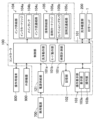
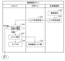
図1はインクジェット記録システムSの全体構成を例示する図である。また、図2はインクジェット記録装置Iの概略構成を例示する図であり、図3はインクジェット記録装置Iにおける印字ヘッド1の概略構成を例示する図である。そして、図4は、インクジェット記録装置Iにおけるインクおよび溶剤の経路を例示する図である。図1に例示する自動印字システムSは、例えば工場等の搬送ラインLに設置されており、その搬送ラインLを流れる各ワークWに対し、順番に印字を施すように構成されている。なお、本開示の適用対象は、自動印字システムSには限定されない。自動以外の方法を用いた印字システムに適用することもできる。搬送ラインLは、例えばベルトコンベア等で構成することができる。
<Overall composition>
FIG. 1 is a diagram illustrating an example of the overall configuration of an inkjet recording system S. FIG. 2 is a diagram illustrating a schematic configuration of an inkjet recording apparatus I, and FIG. 3 is a diagram illustrating a schematic configuration of a
具体的に、自動印字システムSは、粒子状のインク(インク粒)をワークWに着弾させることで印字を行うインクジェット記録装置Iと、インクジェット記録装置Iに接続される操作用端末800及び外部機器900と、インクジェット記録装置Iに接続されて印字ヘッド1の洗浄を行う洗浄載置部200と、を備えている。なお、操作用端末800および外部機器900は、必須ではない。
Specifically, the automatic printing system S includes an inkjet recording device I that performs printing by depositing particulate ink (ink grains) on a workpiece W, an
図1~図3に例示するインクジェット記録装置Iは、インク粒をノズル12から吐出するとともに、そのインク粒をワークWに着弾させる印字ヘッド1と、この印字ヘッド1に対し制御信号、インクおよび溶剤を供給するコントローラ100と、を備えている。コントローラ100が印字ヘッド1に制御信号を供給することで、インク粒の軌跡を制御する。これにより、ワークW上でのインク粒の着弾位置が調整されて、所望の印字が実現されるようになっている。
The inkjet recording device I illustrated in Figures 1 to 3 includes a
特に、本実施形態に係るインクジェット記録装置Iは、いわゆるコンティニュアス方式のインクジェットプリンタ(Continuous Ink Jet printer:CIJ)として構成されている。すなわち、インクジェット記録装置Iは、インクの揮発に起因した目詰まり(特に、ノズル12の目詰まり)等を防止するために、印字を実行していないときであっても、インクジェット記録装置Iが稼働状態であれば、インクジェット記録装置Iの内部を常にインクが循環している。コンティニュアス方式を採用することで、インクによる目詰まりを招くことなく、速乾性のインクを用いることができるようになる。 In particular, the inkjet recording device I according to this embodiment is configured as a so-called continuous ink jet printer (CIJ). That is, in order to prevent clogging (particularly clogging of nozzles 12) caused by ink volatilization, ink is constantly circulating inside the inkjet recording device I even when printing is not being performed, as long as the inkjet recording device I is in operation. By adopting the continuous method, it becomes possible to use quick-drying ink without causing clogging due to ink.
また、本実施形態に係るインクジェット記録装置Iは、溶剤を印字ヘッド1へ送り出すことで、ノズル12等、印字ヘッド1の各部を洗浄することができるようになっている。洗浄に用いられた溶剤は、必要に応じて回収されて、インクの濃度(粘度)を調整するために再利用することができる。
The inkjet recording device I according to this embodiment is also capable of cleaning each part of the
インクの循環を実現するために、印字ヘッド1は、インクまたは溶剤を吐出するノズル12に加えて、そのノズル12から吐出されたインクまたは溶剤を回収するガター16を備えている(図3参照)。コントローラ100から印字ヘッド1へ送り込まれたインクまたは溶剤は、ノズル12から吐出されてガター16によって回収される。そうして回収されたインクまたは溶剤は、コントローラ100へ送り戻されて再利用される。こうした工程を繰り返し行うことで、インクを循環させることができる。
To achieve ink circulation, the
操作用端末800は、例えば中央演算処理装置(Central Processing Unit:CPU)および記憶装置を有しており、コントローラ100に接続されている。この操作用端末800は、印字における加工条件を設定するとともに、印字に関連した情報をユーザに示すための端末として機能する。
The
操作用端末800により設定される加工条件は、コントローラ100に出力されて、その記憶部102に記憶される。コントローラ100の記憶部102に加えて、または、この記憶部102に代えて、操作用端末800が加工条件を記憶してもよい。
The processing conditions set by the
なお、本実施形態に係る加工条件には、印字されるべき文字列等の内容に加えて、後述の立下処理に関連した条件およびパラメータ(以下、これを「洗浄設定」ともいう)が含まれる。 In addition to the content of the text to be printed, the processing conditions in this embodiment also include conditions and parameters related to the start-up process (hereinafter referred to as "cleaning settings"), which will be described later.
なお、操作用端末800は、例えばコントローラ100に組み込んで一体化することができる。この場合は「操作用端末」という呼称ではなく、コントロールユニット等の呼称が用いられることになる。
The
外部機器900は、必要に応じてコントローラ100に接続される。図1および図2に示す例では、外部機器900として、ワーク検出センサ901、搬送速度センサ902およびプログラマブルロジックコントローラ(Programmable Logic Controller:PLC)903が設けられている。
The
具体的に、ワーク検出センサ901は、搬送ラインLにおけるワークWの有無を検出し、その検出結果を示す信号(検出信号)をコントローラ100へ出力する。ワーク検出センサ901から出力される検出信号は、印字を開始するためのトリガー(印字トリガ)として機能する。
Specifically, the
搬送速度センサ902は、例えばロータリエンコーダから構成されており、ワークWの搬送速度を検出することができる。搬送速度センサ902は、その検出結果を示す信号(検出信号)をコントローラ100へ出力する。コントローラ100は、搬送速度センサ902から入力された検出信号に基づいて、印字ヘッド1からインク粒を吐出するタイミング等を制御する。
The
またPLC903は、図2に例示するように、コントローラ100と電気的に接続されている。PLC903は、予め定めたシーケンスに従ってインクジェット記録システムSを制御するために用いられる。
The
インクジェット記録装置Iには、上述した機器や装置以外にも、操作および制御を行うための装置、その他の各種処理を行うためのコンピュータ、記憶装置、周辺機器等を接続することもできる。この場合の接続は、例えば、IEEE1394、RS-232、RS-422およびUSB等のシリアル接続、またはパラレル接続としてもよい。あるいは、10BASE-T、100BASE-TX、1000BASE-T等のネットワークを介して電気的、磁気的または光学的な接続を採用することもできる。また、有線接続以外にも、IEEE802等の無線LAN、または、Bluetooth(登録商標)等の電波、赤外線、光通信等を利用した無線接続でもよい。さらに、データの交換や各種設定の保存等を行うための記憶装置に用いる記憶媒体としては、例えば、各種メモリカード、磁気ディスク、光磁気ディスク、半導体メモリ、ハードディスク等を利用することができる。 In addition to the above-mentioned devices and equipment, the inkjet recording apparatus I can also be connected to devices for operating and controlling, computers for performing various other processes, storage devices, peripheral devices, etc. In this case, the connection may be, for example, a serial connection such as IEEE1394, RS-232, RS-422, or USB, or a parallel connection. Alternatively, electrical, magnetic, or optical connections may be adopted via networks such as 10BASE-T, 100BASE-TX, or 1000BASE-T. In addition to wired connections, wireless connections using wireless LANs such as IEEE802, or radio waves, infrared rays, optical communications, etc. such as Bluetooth (registered trademark) may also be used. Furthermore, as storage media used in storage devices for exchanging data and saving various settings, for example, various memory cards, magnetic disks, magneto-optical disks, semiconductor memories, hard disks, etc. can be used.
<コントローラ100>
コントローラ100は、印字ヘッド1を電気的に制御するとともに、印字用のインク、および、インクを希釈するための溶剤を印字ヘッド1へ供給することができるように構成されている。
<
The
具体的に、本実施形態に係るコントローラ100は、電気的な制御に関連した構成要素として、前述の加工条件を記憶する記憶部102と、コントローラ100および印字ヘッド1の各部を制御する制御部101と、ユーザによる操作を受け付けるとともに、ユーザへ情報を表示する操作表示部103と、外部から供給される電力を制御部101へ導く電源供給部121と、を備えている。
Specifically, the
コントローラ100はまた、インク等の供給に関連した構成要素として、印字ヘッド1のノズル12にインクを供給するインク供給部104と、このノズル12およびインク供給部104に溶剤を供給する溶剤供給部105と、を備えている。
The
制御部101と、インク供給部104及び溶剤供給部105とは、別ユニットで構成されていてもよい。記憶部102も、インク供給部104及び溶剤供給部105とは、別ユニットで構成されていてもよい。操作表示部103も、インク供給部104及び溶剤供給部105とは、別ユニットで構成されていてもよい。これらの場合も、構成要素を合わせてコントローラ100とすることができる。
The
(記憶部102)
記憶部102は、後述の操作表示部103、または、操作用端末800を介して設定された加工条件を記憶するとともに、外部からの制御信号に基づいて、記憶された加工条件を制御部101へと出力するように構成されている。
(Memory unit 102)
The
具体的に、記憶部102は、揮発性メモリ、不揮発性メモリ、ハードディスクドライブ(Hard Disk Drive:HDD)、ソリッドステートドライブ(Solid State Drive:SSD)等を用いて構成されており、加工条件を示す情報を一時的または継続的に記憶することができる。なお、操作用端末800をコントローラ100に組み込んだ場合には、操作用端末800が記憶部102を兼用してもよい。
Specifically, the
(制御部101)
制御部101は、記憶部102に記憶された加工条件に基づいて、少なくとも、コントローラ100におけるインク供給部104および溶剤供給部105と、印字ヘッド1におけるノズル12、帯電電極13および偏向電極15と、を制御する。制御部101が各部を制御することにより、ワークWへの印字が所定のタイミングで実施される。
(Control unit 101)
The
具体的に、制御部101は、例えばCPU、メモリ、入出力バス等を有しており、操作表示部103または操作用端末800を介して入力された情報を示す信号と、記憶部102から読み込んだ加工条件を示す信号と、に基づいて制御信号を生成する。制御部101は、そうして生成した制御信号をコントローラ100およびインクジェット記録装置Iの各部へと出力することにより、ワークWに対する印字を制御する。
Specifically, the
例えば制御部101は、ワークWに印字するときには、記憶部102に記憶されたワークWへの印字内容を読み込んで、その印字内容に基づいた制御信号を生成する。そして、制御部101は、その制御信号を帯電電極13へと出力することで、印字内容に対応した着弾位置を実現するようにインク粒の飛翔方向を設定する。
For example, when printing on the workpiece W, the
(操作表示部103)
図1に示すように、操作表示部103は、例えばコントローラ100を構成する筐体等に設けることができるが、筐体とは別に構成し、筐体とは異なる所に設置するようにしてもよい。この操作表示部103は、インクジェット記録装置Iに関連した種々の情報を表示する表示部103aと、例えば、タッチ式操作パネルやボタン、スイッチ等からなる操作部103bと、を備えている。表示部103aは、例えば液晶表示パネルや有機EL表示パネル等で構成されており、制御部101によって制御され、後述するようなユーザインターフェース等も表示可能に構成されている。
(Operation display section 103)
1, the
ユーザが操作表示部103の操作部103bを操作すると、その操作情報が制御部101に入力され、制御部101はどのような操作が行われたか検知することができる。例えば、操作部103bを操作することで、インクジェット記録装置Iの電源ON/OFF等を切替えることや、各種設定、情報の入力等を行うことができる。なお、操作用端末800をコントローラ100に組み込んだ場合には、操作用端末800が操作表示部103を兼用してもよい。操作表示部103の表示部103aは、ユーザに各種情報を通知する通知部であり、また、操作部103bは各種情報を入力可能な入力部である。
When a user operates the
この操作表示部103は、前述の操作用端末800と同様に、印字における加工条件を設定することもできる。操作表示部103により設定される加工条件は、コントローラ100に出力されて、その記憶部102に記憶される。以下の記載では、ユーザが操作表示部103を操作するケースを前提に説明するが、操作表示部103の代わりに操作用端末800を用いることもできる。
This
(インク供給部104)
インク供給部104は、主たる構成要素として、補充用のインクを収容したインクカートリッジ104aと、このインクカートリッジ104aからインクが供給されるメインタンク104bと、インク流通経路104cとを有している。インクカートリッジ104a、メインタンク104bおよび印字ヘッド1は、インク流通経路104cを介して流体的に接続されている。
(Ink supply unit 104)
The
このうち、インクカートリッジ104aは、コントローラ100に対して着脱自在に構成されており、これを付け替えることで、メインタンク104bにインクを補充することができる。
Of these, the
このように、本実施形態に係るインクジェット記録装置Iは、いわゆる“カートリッジ式”のインクジェットプリンタとして構成されているが、この構成には限定されない。例えば、手動で開閉可能なタンクを設けるとともに、そのタンクに対してインクを補充するように構成してもよい。 Thus, the inkjet recording device I according to this embodiment is configured as a so-called "cartridge-type" inkjet printer, but is not limited to this configuration. For example, it may be configured to have a tank that can be opened and closed manually, and to refill the tank with ink.
メインタンク104bは、ノズル12へ供給されるインクを蓄える容器であり、具体的には溶剤によって濃度(粘度)調整されたインクを収容するように構成されている。こうした構成を実現するために、インクカートリッジ104aからメインタンク104bへ至る経路には、溶剤供給用の経路が接続されている。
The
また、インク流通経路104cは、印字ヘッド1にインクを供給するための経路であり、例えば、ノズル12にインクを送り込むための経路と、ガター16からインクを送り戻すための経路と、を有している。ノズル12にインクを送り込むための経路は、インクカートリッジ104aと、メインタンク104bと、ノズル12とを接続している。ガター16からインクを送り戻すための経路は、ガター16と、メインタンク104bとを接続している。これらの経路によって、印字ヘッド1とコントローラ100との間でインクを循環させることができる。
The
後述の如く、インク流通経路104cには、第1バルブV1をはじめとする複数の電磁弁と、インクポンプP1をはじめとする複数のポンプと、が設けられている。このうち、各電磁弁は、制御部101から出力された制御信号を受けて開閉し、インクの流れを制御することができる。一方、各ポンプは、制御部101から出力された制御信号を受けてインクを圧送し、電磁弁と同様に、インクの流れを制御することができる。
As described below, the
(溶剤供給部105)
溶剤供給部105は、主たる構成要素として、補充用の溶剤を収容した溶剤カートリッジ105aと、洗浄に用いられた溶剤を蓄えるコンディショニングタンク105bと、溶剤流通経路105cと、を有している。溶剤カートリッジ105a、コンディショニングタンク105bおよび印字ヘッド1は、溶剤流通経路105cを介して流体的に接続されている。溶剤が流通する溶剤流通経路105cは、複数の経路からなり、そのうちの一部は、ガター16からインクを送り戻す経路により兼用されている。
(Solvent supply unit 105)
The solvent supply unit 105 has, as its main components, a
溶剤カートリッジ105aは、コントローラ100に対して着脱自在に構成されている。この溶剤カートリッジ105aを付け替えることで、コントローラ100に溶剤を補充することができる。溶剤カートリッジ105aの代わりに溶剤タンクを設けてもよい。なお、溶剤供給部105は、溶剤カートリッジ105a内の溶剤が空になったか否か、又は、溶剤が残り少なくなったか否かを検知する機能を有する。溶剤カートリッジ105aに収容されている溶剤は、インクの濃度調整に用いられるとともに、インクが流通する経路等を洗浄する洗浄剤としても使用される。
The
コンディショニングタンク105bは、洗浄に用いられた溶剤を収容するように構成されている。前述のように、ノズル12から吐出された溶剤は、インクと同様にガター16によって回収される。そのため、ガター16からインクを送り戻すための経路は、溶剤を送り戻すための経路を兼用している。
The
また、溶剤流通経路105cは、印字ヘッド1およびメインタンク104b等に溶剤を供給するための経路を含み、例えば、ノズル12に溶剤を送り込むための経路と、ガター16から溶剤を送り戻すための経路と、を有している。ノズル12に溶剤を送り込むための経路は、溶剤カートリッジ105aとノズル12とを接続している。ガター16から溶剤を送り戻すための経路は、前述のように、インクを送り戻すための経路を兼ねている。
The
後述の如く、溶剤流通経路105cには、第16バルブV16をはじめとする複数の電磁弁と、溶剤ポンプP2をはじめとする複数のポンプと、が設けられている。このうち、各電磁弁は、制御部101から出力された制御信号を受けて開閉し、溶剤の流れを制御することができる。一方、各ポンプは、制御部101から出力された制御信号を受けて溶剤を圧送し、電磁弁と同様に、溶剤の流れを制御することができる。
As described below, the
なお、溶剤流通経路105c、および、前述のインク流通経路104cという分類は、説明を簡潔にするためになされた便宜上の分類に過ぎない。溶剤流通経路105cおよびインク流通経路104cは、相互に接続されていたり、一方が他方を兼ねていたりするため、実質的に不可分となっている。
The classification of the
(電源供給部121)
電源供給部121は、商用電源700と制御部101の間に介在しており、商用電源700)から供給される電力を中継し、これを制御部101へと供給することができる。
(Power supply unit 121)
The
(他の構成要素)
コントローラ100には、制御信号を送受するための電気配線と、インクを送受するためのチューブ(具体的には、インク流通経路104cを区画するチューブ)と、溶剤を送受するためのチューブ(具体的には、溶剤流通経路105cを区画するチューブ)と、が束になって被覆された接続ケーブル107が設けられている。この接続ケーブル107は可撓性を有しており、印字ヘッド1の上端部に接続されている(図1を参照)。コントローラ100と印字ヘッド1は、この接続ケーブル107を介して電気的にかつ流体的に接続されている。
(Other components)
The
<印字ヘッド1>
印字ヘッド1は、コントローラ100から供給される制御信号、インクおよび溶剤に基づいて濃度調整されたインクを粒子状のインク粒として吐出する。印字ヘッド1は、そうして吐出されたインク粒の飛翔方向を偏向せしめるとともに、偏向されたインク粒をワークWの表面に着弾させることで、そのワークWに対して印字を実行することができる。
<
The
具体的には、図3に示すように、本実施形態に係る印字ヘッド1は、インクを加振する加振器11と、加振器11により加振されたインクを吐出するノズル12と、ノズル12から吐出された粒子状のインクを帯電させる帯電電極13と、インクの帯電状態を監視する帯電検出センサ14と、帯電電極13により帯電されたインクの飛翔方向を偏向させる偏向電極15と、偏向電極15により非偏向とされたインク、または、ノズル12から吐出された溶剤を回収するガター16と、を備えている。
Specifically, as shown in FIG. 3, the
印字ヘッド1は、加振器11、ノズル12、帯電電極13、帯電検出センサ14、偏向電極15およびガター16を内部に収容し、かつ、インク粒の飛翔空間S1を区画する筐体10を備えている。この印字ヘッド1は、偏向電極15によって偏向されたインク粒を、飛翔空間S1を介して筐体10の外部に吐出することができる。
The
図5にも示すように、印字ヘッド1の外形状をなす筐体10の下面には、偏向電極15により偏向されたインクを外部に吐出するための吐出口Aが開口している。インクは、この吐出口Aから筐体10の下方へ向けて吐出されるようになっている。
As shown in FIG. 5, the underside of the
図1に示すように、印字時における印字ヘッド1は、例えば支持部材2によって支持されている。支持部材2によって支持された状態の印字ヘッド1は、その吐出孔AがワークWの印字面に対して上方向から対向するように配置される。この場所が、インクジェット記録装置Iにより印字を行う際の印字ヘッド1の設置場所の一例である。
As shown in FIG. 1, during printing, the
以下、印字ヘッド1をなす各部について、順番に説明をする。なお、以下の記載において「上下方向」とは、鉛直方向に沿った方向を指す。例えば、図3の紙面上方が「上方向」に相当し、同図の紙面下方が「下方向」に相当する。他の図においても、これに対応する方向を「上下方向」という。
Below, each part of the
(加振器11)
図3に例示するように、加振器11は、筐体10の飛翔空間S1における上端付近に配置されている。本実施形態に係る加振器11には、インクに上下振動を付与(加振)するためのデバイス(例えばピエゾ素子)が内蔵されている。この加振器11は、接続ケーブル107を介してインクが供給されるように構成されており、そうして供給されたインクを加振することができる。加振器11によって加振されたインクは、ノズル12へと供給される。
(Vibrator 11)
3, the
なお、図示は省略したが、本実施形態に係る加振器11は接地されている。
Although not shown in the figure, the
(ノズル12)
図3に例示するように、ノズル12は、加振器11の下端部に接続されており、その開口端(インクの噴射口)を下方に向けた姿勢で配置されている。ノズル12の開口端から、加振器11によって加振されたインクを吐出することができる。このノズル12には、例えば立下時に印字ヘッド1内部の圧力を抜くためのリターン経路として機能する吸引経路27が接続されている(図4を参照)。また、吸引経路27を通じて、ノズル12から溶剤を吸引させることもできる。
(Nozzle 12)
As shown in Fig. 3, the
ここで、加振器11によって加振されずにノズル12から吐出されたインクは、軸状のいわゆる“インク軸”となって流れる。一方、加振されたインクは、ノズル12から吐出された直後に粒子化されて、いわゆる“インク粒”となる。ノズル12から吐出されたインクは、ノズル12から吐出された直後は軸状であるが、ノズル12から離れるに従って粒子状になる。この粒子状になる位置をブレークポイントと呼ぶ。ノズル12から吐出されたインク(インク粒)は、後述する帯電電極13を通過する。
Here, the ink ejected from the
なお、印字ヘッド1を洗浄すべく供給された溶剤は、加振器11とノズル12を順番に通過して、ノズル12の先端部から吐出される。そうして吐出される溶剤は、軸状に流れて、帯電電極13を通過する。
The solvent supplied to clean the
(帯電電極13)
図3に例示するように、帯電電極13は、一対の伝導性を有する金属板によって構成されており、ノズル12の下方に配置されている。ここで、帯電電極13を構成する一対の金属板は、それぞれの長手方向を上下方向に沿わせた姿勢で、かつ互いに水平方向に向い合うような姿勢で筐体10に固定されている。一対の金属板の間隔は、ノズル12から吐出されたインクの粒径よりも大きく設定されており、ノズル12から吐出されたインクが一対の金属板の間を通過することになる。
(Charged electrode 13)
3, the charged
本実施形態に係る帯電電極13には、少なくとも印字動作を実行するときに電位(正電位)が印加される。これにより、加振器11と帯電電極13との間に電位差を生じさせ、帯電電極13を通過するインク粒を帯電させることが可能となる。各インク粒を帯電させるために、本実施形態に係る帯電電極13は、ノズル12から吐出されたインクが粒子化するブレークポイント付近に配置される。
A potential (positive potential) is applied to the charging
帯電電極13には、コントローラ100によって制御可能なパルス電位が印加される。ここで、帯電電極13に対して相対的に高い電圧を印加した場合は、それよりも低い電圧を印加した場合に比して、各インク粒の帯電量(負の電荷の大きさ)が大きくなる。各インク粒は、その帯電量が大きい場合には、それが小さい場合に比して、偏向電極15によって大きく偏向される。コントローラ100がパルス電位の大きさを調整することで、インク粒の偏向量を制御することができる。帯電電極13によって帯電されたインク粒は、帯電検出センサ14の側方を通過した偏向電極15へ至る。
A pulse potential that can be controlled by the
また、ノズル12から吐出される溶剤は、帯電されることなく、帯電検出センサ14の側方を通過して偏向電極15へ至る。
The solvent discharged from the
(帯電検出センサ14)
図3に例示するように、帯電検出センサ14は、帯電電極13の下方に配置されている。詳しくは、帯電検出センサ14は、帯電電極13を構成する金属板(図3に示す例では、紙面右側の金属板)の下方において、インク粒が飛翔する際の軌跡と交わらないように配置されている。帯電検出センサ14をこのように配置することで、インク粒と帯電検出センサ14との衝突を避けることが可能となる。
(Charge detection sensor 14)
3, the
また、本実施形態に係る帯電検出センサ14は、筐体10の内部に設けた回路基板に接続されている。帯電検出センサ14は、その側方を通過するインク粒の帯電状態を検出することができる。帯電検出センサ14による検出結果は、検出信号として制御部101に出力される。この検出信号に基づいて、制御部101は、各インク粒が適切に帯電しているか否かを判定することができる。
The
(偏向電極15)
図3に例示するように、偏向電極15は、一対の伝導性を有する金属板(いわゆる「対向電極」)によって構成されており、帯電電極13および帯電検出センサ14の下方に配置されている。ここで、一対の金属板は、それぞれの長手方向を略上下方向に沿わせた姿勢で、かつ互いに水平方向に向い合うような姿勢で筐体10に固定されている。帯電電極13を構成する一対の金属板の間を通過したインク粒は、偏向電極15を構成する一対の金属板の間を通過することになる。
(Deflection electrode 15)
3, the
偏向電極15には、コントローラ100によって制御可能な電圧が印加される。これにより、偏向電極15を構成する一対の金属板の間には電位差が生じることになる。この電位差によって、インク粒の帯電量に応じて、そのインク粒の飛翔方向を偏向させることができる。インク粒の飛翔方向は、偏向電極15を構成する一対の金属板の並び方向に沿って偏向され得る。
A voltage that can be controlled by the
すなわち、帯電電極13および偏向電極15のそれぞれに印加される電圧を介して、インク粒の飛翔方向を制御することができる。そうして飛翔方向が制御されるインク粒には、偏向電極15により偏向されたものと、偏向電極15により偏向されないもの(非偏向とされたもの)と、が含まれる。このうち、偏向電極15により偏向されたインク粒がワークWの印字に関与する。偏向電極15により偏向されたインク粒は、筐体10の下面に設けた吐出口Aから吐出されて、ワークWに着弾する。
That is, the flight direction of the ink particles can be controlled via the voltages applied to the charged
一方、偏向電極15により非偏向とされたインク粒は、ワークWの印字に関与しない。こうしたインク粒、または、そもそも粒子化されていない軸状のインクは、図3において鎖線で例示したように、ガター16の中に到達する。同様に、印字ヘッド1におけるノズル12等の洗浄に用いられて偏向電極15を通過した溶剤もまた、ガター16の中に至る。
On the other hand, ink particles that are not deflected by the
(ガター16)
図3に例示するように、ガター16は、その開口端を上方に向けた曲管によって構成されており、偏向電極15の下方に配置されている。本実施形態に係るガター16は、ワークWの印字に関与しないインクと、ノズル12を通過した溶剤(具体的には、ノズル12から吐出された溶剤)と、を回収することができる。
(Gutter 16)
3, the
詳しくは、本実施形態においては、ガター16の開口端(上流端)と、ノズル12の開口端とが互いに向い合うように配置されており、ガター16の開口端の真上にノズル12の開口端が位置している。このように配置することで、ノズル12の開口端から鉛直方向に沿って流れた流体を、ガター16の開口端から受け入れることが可能になる。
More specifically, in this embodiment, the open end (upstream end) of the
ガター16によって回収されたインクまたは溶剤は、インク流通経路104c、溶剤流通経路105c等を通じてコントローラ100に送り戻されて、メインタンク104bまたはコンディショニングタンク105bに蓄えられるようになっている。
The ink or solvent collected by the
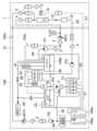
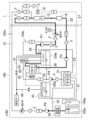
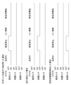
以下、ガター16によるインクまたは溶剤の回収について詳細に説明するために、インク流通経路104cおよび溶剤流通経路105cに係る構成について、図4を用いて説明をする。なお、図4において符号Fが付された構成要素は、フィルタを例示している。以下の記載では、フィルタFの配置、構成等の説明を省略する。
Below, in order to provide a detailed explanation of the recovery of ink or solvent by the
<インクおよび溶剤の経路について>
前述のように、本実施形態に係るコントローラ100は、印字ヘッド1にインクを供給するためのインク流通経路104cと、印字ヘッド1およびメインタンク104b等に溶剤を供給するための溶剤流通経路105cと、を備えている。
<Ink and solvent routes>
As described above, the
具体的に、インク流通経路104cは、ノズル12へのインクの供給に関連した経路として、インクカートリッジ104aおよび第1分岐部51を接続する第1インク経路21と、第1分岐部51(詳細には、第2インク経路22における中途の部位)、および、第2分岐部52を接続する第6インク経路26と、第2分岐部52およびメインタンク104bを接続する第8インク経路28と、メインタンク104bおよびノズル12を接続する第4インク経路24と、を有している。ここで、本実施形態に係る第6インク経路26は、後述の第5インク経路25を介して第2分岐部52と接続されるようになっている。
Specifically, the
また、インク流通経路104cは、粘度計53による粘度測定に関連した経路として、第1分岐部51およびメインタンク104bを接続し、かつ粘度計53が介設された第2インク経路22と、この第2インク経路22とは独立して設けられ、メインタンク104bおよび第1分岐部51を接続する第3インク経路23と、を有している。
The
また、インク流通経路104cは、ガター16によるインクの回収に関連した経路として、ガター16およびメインタンク104bを接続する第5インク経路25を有している。
In addition, the
ここで、第2インク経路22には、循環ポンプP4と、第11バルブV11と、粘度計53と、が順番に設けられている。第4インク経路24には、インクポンプP1と、減圧弁と、圧力計と、第14バルブV14と、が順番に設けられている。第5インク経路25には、第10バルブV10と、ガターポンプP3と、第2分岐部52と、が順番に設けられている。
Here, the
一方、溶剤流通経路105cは、ノズル12への溶剤の供給に関連した経路として、溶剤カートリッジ105aおよびノズル12を接続する第1溶剤経路31を有している。
On the other hand, the
また、溶剤流通経路105cは、溶剤カートリッジ105aに収容された溶剤によるインクの濃度(粘度)調整に関連した経路(溶剤カートリッジ105aとメインタンク104bとを結ぶ経路の一部要素)として、第1溶剤経路31における中途の部位、および、第1分岐部51を接続する第2溶剤経路32を有していてもよい。
The
また、溶剤流通経路105cは、コンディショニングタンク105bに収納された溶剤による濃度調整に関連した経路(メインタンク104bとコンディショニングタンク105bとを結ぶ経路の一部要素)として、第1分岐部51とコンディショニングタンク105bを接続する第3溶剤経路33を有していてもよい。
The
なお、インク流通経路104cとして例示された第5インク経路25は、ガター16による溶剤の回収に関連している。前述のように、「インク流通経路104c」および「溶剤流通経路105c」という分類は、便宜上の分類に過ぎない。
The
ここで、第1溶剤経路31には、光学式空検知機構44と、溶剤ポンプP2と、第16バルブV16と、第12バルブV12と、が順番に設けられている。第1溶剤経路31には、溶剤噴射部としての洗浄ノズル19が接続されている。洗浄ノズル19は、印字ヘッド1における加振器11、ノズル12の先端部、帯電電極13、偏向電極15等に溶剤を噴射することによってそれらを洗浄するためのノズルであって、洗浄液としての溶剤を噴出することができる。洗浄ノズル19から第1溶剤経路31に至る途中には、第15バルブV15が設けられている。
Here, the first
ここで、第1分岐部51は、第3インク経路23および第2インク経路22の間を開閉する第5バルブV5と、第1インク経路21および第2インク経路22の間を開閉する第8バルブV8と、第3溶剤経路33および第2インク経路22の間を開閉する第9バルブV9と、第2溶剤経路32および第2インク経路の間を開閉する第13バルブV13と、を有している。
Here, the
また、第2分岐部52は、第6インク経路26および第8インク経路28の間を開閉する第1バルブV1と、第6インク経路26およびコンディショニングタンク105bの間を開閉する第3バルブV3と、第6インク経路26および廃液タンク(図4において、「廃液」と図示)の間を開閉する第4バルブV4と、を有している。
The
制御部101は、第11バルブV11など、各経路に設けられたバルブに制御信号を出力したり、第1分岐部51および第2分岐部52をなす各バルブに制御信号を出力したりすることで、コントローラ100内に所望の流路を構成することができる。
The
例えば、第8バルブV8と第1バルブV1を開くことで、インクカートリッジ104aからメインタンク104bにインクを補充することが可能になる。また、本来の循環動作ではないが、第5バルブV5と第11バルブV11を開くことで、第2インク経路22と、メインタンクと、第3インク経路23と、の間でインクを循環させて、粘度計53によってインクの粘度を測定することが可能になる。
For example, by opening the eighth valve V8 and the first valve V1, it becomes possible to refill the
溶剤に関連した経路についても同様である。例えば、第13バルブV13と、第1バルブV1と、を開くことで、溶剤カートリッジ105aに収容された溶剤をメインタンク104bに供給し、同タンクに蓄えられたインクの濃度を調整することができるようになる。また、第9バルブV9と、第1バルブV1と、を開くことで、コンディショニングタンク105bに貯蔵されたインク混じりの溶剤が、第3溶剤経路33、第1分岐部51、第6インク経路26、第2分岐部52および第8インク経路28を通過して、メインタンク105aに供給される。
The same is true for paths related to the solvent. For example, by opening the thirteenth valve V13 and the first valve V1, the solvent contained in the
コントローラ100は、空気の流通に関連した経路も有している。例えば、メインタンク104bには、不図示の排気口に通じる第1排気管41が接続されている。同様に、コンディショニングタンク105bには、前記排気口に通じる第2排気管42が接続されている。
The
空気の流通に関連した経路の別例として、コントローラ100は、ノズル12および第1分岐部51を接続する吸引経路27を有している。吸引経路27には第6バルブV6が設けられていて、この第6バルブV6と、前述の第5バルブV5を開くことで、吸引経路27、第1分岐部51、第6インク経路26、第2分岐部52、第8インク経路28、メインタンク104bおよび第1排気管41を介してノズル12を大気と連通させることができる。これにより、ノズル12から吐出されるインク粒の噴射圧を調整することができるようになる。
As another example of a path related to air circulation, the
また、印字を実施する際には、第14バルブV14を開くことで、メインタンク104bから第4インク経路24を介してインクが供給される。そうして供給されたインクは、粒子状のインク粒となってノズル12から吐出される。
When printing is to be performed, the 14th valve V14 is opened, and ink is supplied from the
ここで、ノズル12から吐出されたインク(インク粒)のうち、印字に関与するインクは、図3を用いて説明したように印字ヘッド1から吐出される。一方、印字に関与しないインク、および、ノズル12等の洗浄に用いられた溶剤は、ガター16に回収されて、第5インク経路25を通じてコントローラ100に送り戻される。
Of the ink (ink particles) ejected from the
その場合、メインタンク104bに送り戻されるべきインクは、第1分岐部51から、第6インク経路26、及び、第2分岐部52における第1バルブV1、および、第8インク経路28を介してメインタンク104bに供給される。一方、コンディショニングタンク105bに送り戻されるべき溶剤は、第5経路25から、第2分岐部52における第3バルブV3を介してコンディショニングタンク105bに供給される。
In this case, the ink to be returned to the
ガター16によるインクまたは溶剤の回収は、例えば、インクジェット記録装置Iの立上処理および立下処理と関連して行われるようになっている。ここで、「立上処理」とは、インクジェット記録装置Iへの電源投入時に、印字を開始する前に実行される処理をいう。一方、「立下処理」とは、インクジェット記録装置Iの電源遮断時に、同装置の動作を停止する前に実行される処理をいう。
The recovery of ink or solvent by the
詳しくは、本実施形態に係るインクジェット記録装置Iは、電源スイッチがONにされても、印字を直ちには開始しない。インクジェット記録装置Iは、印字を開始する前に所定の立上処理を実行する。この立上処理においては、溶剤を用いて印字ヘッド1を洗浄した後に、インクの吐出が開始される。立上処理の開始直後に吐出されるインクは、前述したインク軸を形成し、ガター16によって回収される。
More specifically, the inkjet recording device I according to this embodiment does not immediately start printing even when the power switch is turned on. The inkjet recording device I executes a predetermined start-up process before starting printing. In this start-up process, the
同様に、本実施形態に係るインクジェット記録装置Iは、電源スイッチがOFFにされようとしたときには、その動作を直ちには停止しない。インクジェット記録装置Iは、動作を停止する前に、ノズル洗浄などからなる所定の立下処理を実行する。この立下処理においては、ノズル12から溶剤を吐出させて、これに残存したインクを洗浄および回収することができる。溶剤の吐出に伴ってノズル12から排出されたインクは、立上処理におけるインク軸と同様に、ガター16によって回収される。
Similarly, the inkjet recording device I according to this embodiment does not immediately stop operation when the power switch is turned off. Before stopping operation, the inkjet recording device I executes a predetermined shutdown process, which includes nozzle cleaning. In this shutdown process, a solvent is ejected from the
なお、本実施形態における「電源スイッチ」には、物理的な押し釦に加えて、操作表示部103等に表示されるタッチ式操作パネルで構成されるスイッチ類も含む。そして、電源スイッチのOFF操作とは、押し釦等を物理的に押下する操作に加えて、操作用端末800、操作表示部103等を通じて指令されるシャットダウン操作も指す。電源スイッチのON操作についても同様である。
In addition, the "power switch" in this embodiment includes not only a physical push button, but also switches configured with a touch-type operation panel displayed on the
以下、インクジェット記録装置Iの立上処理および立下処理について詳細に説明する。 The start-up and shut-down processes of the inkjet recording device I are described in detail below.
<インクジェット記録装置Iの基本動作>
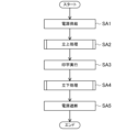
図6は、インクジェット記録装置Iの基本動作を例示するフローチャートである。このフローチャートは、立上処理をはじめとするインクジェット記録装置Iの基本動作を例示している。
<Basic Operation of Inkjet Recording Apparatus I>
6 is a flow chart illustrating an example of the basic operation of the inkjet recording apparatus I. This flow chart illustrates an example of the basic operation of the inkjet recording apparatus I, including the start-up process.
まず、図6のステップSA1では、インクジェット記録装置Iの電源スイッチがOFFFからONにされて、インクジェット記録装置Iに電源が投入される。 First, in step SA1 of FIG. 6, the power switch of the inkjet recording device I is turned from OFF to ON, and power is applied to the inkjet recording device I.
ステップSA1から続くステップSA2において、制御部101が立上処理を実行する。
In step SA2, which follows step SA1, the
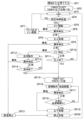
図7は、インクジェット記録装置Iの立上処理を例示するフローチャートである。このフローチャートは、図6におけるステップSA2の詳細を例示している。すなわち、図7における4つのステップSB1、SB2、SB3、SB4が、図6のステップSA2を構成している。 Figure 7 is a flow chart illustrating the start-up process of the inkjet recording device I. This flow chart illustrates the details of step SA2 in Figure 6. In other words, the four steps SB1, SB2, SB3, and SB4 in Figure 7 constitute step SA2 in Figure 6.
また、図8は立上処理における工程Aを説明するための図であり、図9は立上処理における工程Bを説明するための図であり、図10は立上処理における工程Cを説明するための図である。 Figure 8 is a diagram for explaining step A in the start-up process, Figure 9 is a diagram for explaining step B in the start-up process, and Figure 10 is a diagram for explaining step C in the start-up process.
ステップSB1においては、制御部101が工程Aを実行し、インクジェット記録装置Iにおけるインクおよび溶剤の経路を昇圧する。この工程Aにおいては、溶剤を準備するために、制御部101は、第16バルブV16を開いた状態で、第12バルブV12を閉状態で待機させる。その状態で溶剤ポンプP2が作動することで、溶剤カートリッジ105aに収容された溶剤が、第1溶剤経路31を介して第12バルブV12付近まで供給される(図8の太線を参照)。
In step SB1, the
また、インクを準備するために、制御部101は、第14バルブV14を閉状態で待機させる。その状態でインクポンプP1が作動することで、第4インク経路24内のインクの圧力が上昇する(図8の太線を参照)。
To prepare the ink, the
また、ガター16を準備するために、制御部101は、第10バルブV10および第1バルブV1を開状態で待機させる。その状態でガターポンプP3が作動することで、ガター16によって回収されたインクまたは溶剤を、第5インク経路25および第2分岐部52を介してメインタンク104bまで送り戻すことができるようになる(図8の太線を参照)。
To prepare the
工程Aにおいて、制御部101には、圧力計の検知信号が入力される。制御部101は、そうした検知信号に基づいて、第4インク経路24の圧力が規定値以上になるまで待機する。
In step A, a detection signal from the pressure gauge is input to the
ステップSA1から続くステップSA2では、制御部101が工程Bを実行し、ノズル12から溶剤を吐出させる。この工程Bにおいては、制御部101が第12バルブV12を開くことで、ノズル12から溶剤が吸い出されて吐出される。そうして吐出された溶剤は、ガター16によって回収される。この工程Bは、1秒未満の短期間にわたって実行されるため、他の工程に比して、少量の溶剤が吐出されることになる。そのため、工程Bにおいて吐出される溶剤は、第1バルブV1を介して第5インク経路25からメインタンク104bに送り戻される(図9の太線を参照)。
In step SA2, which follows step SA1, the
なお、工程Bにおいて多量の溶剤が噴射される場合は、第1バルブV1ではなく第3バルブV3が開放されて、第5インク経路25からコンディショニングタンク105bへ溶剤が送り戻される。
When a large amount of solvent is sprayed in process B, the third valve V3 is opened instead of the first valve V1, and the solvent is sent back from the
ステップSA2から続くステップSA3では、制御部101が工程Cを実行し、ノズル12からインクを吐出させる。この工程Cにおいては、インクを吐出させるために、制御部101は、第12バルブV12を閉じて第14バルブV14を開く。これにより、ノズル12から軸状のインク(インク軸)が吐出される。そうして吐出されたインクは、ガター16によって回収される。そうして回収されたインクは、第1バルブV1を介して第5インク経路25からメインタンク104bに送り戻される(図10の太線を参照)。
In step SA3, which follows step SA2, the
ステップSA3から続くステップSA4では、制御部101が、ノズル12から吐出されるインクへの加振、並びに、帯電電極13および偏向電極15への印加を開始させる。これにより、インクを粒子化させたり、帯電させたり、偏向させたりすることが可能となる。
In step SA4, which follows step SA3, the
ステップSA4に示す処理が終了するとリターンされて、図7に示す制御プロセスから図6に示す制御プロセスに戻る。そして、制御部101が、ステップSA2から続くステップSA3を実行する。
When the process shown in step SA4 is completed, a return is made and the control process shown in FIG. 7 returns to the control process shown in FIG. 6. Then, the
ステップSA3において、制御部101は、粒子状のインク(インク粒)をワークWに着弾させることで、そのワークWに対して印字を行う。
In step SA3, the
ワークWへの印字動作を開始すると、図3に示すように、加振器11によって加振されたインクがノズル12から吐出される。このインクは、コントローラ100のインク供給部104から適宜供給されるようになっている。ノズル12から吐出されたインクは、その吐出直後から粒子化を開始し、粒子化した段階で帯電電極13によって帯電される。帯電電極13によって帯電されたインク粒は、帯電検出センサ14によって帯電状態が検出された上で、偏向電極15を通過する。
When the printing operation on the workpiece W is started, as shown in FIG. 3, ink vibrated by the
そして、偏向電極15によって飛翔方向が偏向されたインク粒は、筐体10内の飛翔区間S1を通過して、印字ヘッド1の外部に吐出される。印字ヘッド1から吐出されたインク粒は、図1に示すように、ワークWの表面上に着弾して文字や図形を形成する。ここで、インク粒の着弾位置は、各インク粒の帯電量と、偏向電極15への印加電圧を介して制御される。
The ink particles, whose flight direction has been deflected by the
また、前述のように、本実施形態に係るインクジェット記録装置Iは、コンティニュアス方式のインクジェットプリンタとして構成されているため、立上処理後の印字可能状態(インクジェット記録装置Iの稼働状態)にあっては、印字を実行しないときであっても、ノズル12からインクが吐出され続けるようになっている。このときに吐出されるインクは、偏向電極15によって偏向されない(換言すれば、「非偏向」とされる)。非偏向とされたインクは、印字に関与することなく、ガター16により回収されて装置内部を循環し、再利用される。
As described above, the inkjet recording device I according to this embodiment is configured as a continuous-type inkjet printer, so that in a printable state after start-up processing (operating state of the inkjet recording device I), ink continues to be ejected from the
ここで、印字が滞りなく完了し、インクジェット記録装置Iが正常にシャットダウンされる場合を考える。具体的に、ステップSA3において、インクジェット記録装置Iの電源スイッチがONからOFFに切り替えられようとしたものとする。 Now consider the case where printing is completed without any problems and the inkjet recording device I is shut down normally. Specifically, assume that in step SA3, the power switch of the inkjet recording device I is about to be switched from ON to OFF.
この場合、ステップSA4において、制御部101が立下処理を実行する。この立下処理は、本実施形態における「洗浄動作」の例示である。洗浄動作は、制御部101の洗浄動作部101aが実行する。
In this case, in step SA4, the
図11は、インクジェット記録装置Iの立下処理を例示するフローチャートである。このフローチャートは、図6におけるステップSA4の詳細を例示している。すなわち、図11における5つのステップSC1~ステップSC5が図6のステップSA4を構成している。 Figure 11 is a flow chart illustrating the shut-down process of the inkjet recording device I. This flow chart illustrates the details of step SA4 in Figure 6. In other words, the five steps SC1 to SC5 in Figure 11 constitute step SA4 in Figure 6.
また、図12は立下処理における工程Dを説明するための図であり、図13は立下処理における工程Eを説明するための図であり、図14は立下処理における工程Fを説明するための図である。 In addition, FIG. 12 is a diagram for explaining step D in the falling process, FIG. 13 is a diagram for explaining step E in the falling process, and FIG. 14 is a diagram for explaining step F in the falling process.
ステップSC1においては、制御部101が、ノズル12から吐出されるインクへの加振、並びに、帯電電極13および偏向電極15への電圧印加を停止する(インクの粒子化、帯電、偏向:ON→OFF)。これにより、インクの粒子化、帯電および偏向が停止され、ノズル12からは軸状のインク軸が吐出されるようになる。
In step SC1, the
ステップSC1から続くステップSC2では、制御部101が、インク軸の吐出を停止させる(インクの吐出停止)。具体的に、このステップSC2では、インクの吐出を停止するために、制御部101は、第14バルブV14を閉じる。これにより、ノズル12からインクが吐出されないようになる。
In step SC2, which follows step SC1, the
ステップSC2から続くステップSC3では、制御部101が、溶剤の間欠吐出を実行する(溶剤の間欠噴出)。具体的に、制御部101は、溶剤を間欠的に吐出させるために、図12に例示する工程Dと、図13に例示する工程Eと、を交互に実行する。溶剤を間欠的に吐出することで、インクジェット記録装置I、特に印字ヘッド1をなすノズル12を洗浄することができる。以下、この動作を「間欠噴出動作」という。
In step SC3, which follows step SC2, the
このうち、図12に示す工程Dにおいては、制御部101は、第16バルブV16と、第12バルブ(溶剤噴射バルブともいう。)V12と、第10バルブV10と、第1バルブV1と、を開く。その状態で溶剤ポンプP2およびガターポンプP3を作動させることで、溶剤カートリッジ105aに収容された溶剤が、第1溶剤経路31を介してノズル12から吐出されてガター16により回収される。ガター16により回収された溶剤は、第5インク経路25および第2分岐部52を介してメインタンク104bに送り戻される(図12の太線を参照)。
In step D shown in FIG. 12, the
図11に示す処理を開始した直後は、第5インク経路25に多くのインクが残存していると考えられるため、図12に示す工程Dにおける溶剤は、コンディショニングタンク105bではなく、メインタンク104bへ送り戻されるようになっている。
Immediately after starting the process shown in FIG. 11, it is believed that a large amount of ink remains in the
また、図13に示す工程Eにおいては、制御部101は、第12バルブV12を閉じて、第6バルブV6を開く。そうすると、循環ポンプP4が及ぼす負圧によって、ノズル12に残存した溶剤が、吸引経路27、第1分岐部51、第6インク経路26、第1バルブV1、第8インク経路28を介してメインタンク104bに吸い込まれるようになる(図13の太線を参照)。
In addition, in step E shown in FIG. 13, the
なお、図13に示す工程Eにおいては、第12バルブV12を閉じずに、開いたままとしてもよい。その場合、溶剤カートリッジ105aからノズル12へ溶剤が供給されつつも、そうして供給された溶剤がそのまま、吸引経路27から吸い込まれるようになる。こうすることで、第6バルブV6を流れる溶剤の流量を向上させ、より十分に洗浄することができるようになる。
In step E shown in FIG. 13, the twelfth valve V12 may be left open rather than closed. In that case, while the solvent is being supplied from the
図12に示す工程Dと図13に示す工程Eとは、複数回(例えば数セット)にわたって繰り返される。ここで、ステップSC3において工程Dを実施する時間(例えば1秒未満)は、工程Eを実施する時間(例えば数秒程度)よりも短い。 Step D shown in FIG. 12 and step E shown in FIG. 13 are repeated multiple times (e.g., several sets). Here, the time for performing step D in step SC3 (e.g., less than one second) is shorter than the time for performing step E (e.g., several seconds).
また、工程Eにおいて第12バルブV12を閉じた後に、工程Dにおいて第12バルブV12を開くことで、溶剤が間欠的に噴射されるようになる。工程Dから工程Eへ移行する際に、数秒程度にわたって第12バルブV12を閉じてもよい。こうすることで、第12バルブV12付近における溶剤の圧力を高めることができ、第12バルブV12を開いたときに、溶剤を勢いよく吐出することができるようになる。 In addition, after closing the 12th valve V12 in step E, the 12th valve V12 is opened in step D, so that the solvent is sprayed intermittently. When transitioning from step D to step E, the 12th valve V12 may be closed for a few seconds. This increases the pressure of the solvent near the 12th valve V12, so that the solvent can be forcefully ejected when the 12th valve V12 is opened.
ステップSC3から続くステップSC4において、制御部101が図12に示す工程Dのみを実行し、ノズル12から溶剤を吐出させる。このステップSC4において工程Dを実施する時間は、例えば30秒程度であり、ステップSC3において工程Dを実施する時間よりも長い。このステップSC4を実行することで、主に、ガター16に通じる第5インク経路25を洗浄することができる。以下、この動作を「ガター洗浄動作」という。
In step SC4, which follows step SC3, the
ステップSC4から続くステップSC5において、制御部101が図14に示す工程Fを実行し、印字ヘッド1から溶剤を回収する。具体的に、この工程Fにおいて、制御部101は、第10バルブV10および第3バルブV3を開く。その状態でガターポンプP3が作動することで、ノズル12に残存した溶剤が、第5インク経路25および第2分岐部52を介してコンディショニングタンク105bに吸引される(図14の太線を参照)。このステップS65を実行することで、洗浄に用いた溶剤を回収することができる。
In step SC5, which follows step SC4, the
ステップSC5が実行される前に、ステップSC4において溶剤を吐出させたため、第5インク経路25には相対的に多くの溶剤が残存していると考えられる。そのため、工程Fにおける溶剤は、メインタンク104bではなく、コンディショニングタンク105bへと送り戻されるようになっている。
Because the solvent was ejected in step SC4 before step SC5 was executed, it is believed that a relatively large amount of solvent remains in the
ステップSC5に示す処理が終了するとリターンされて、図11に示す制御プロセスから図6に示す制御プロセスに戻る。そして、ステップSA4から続くステップSA5では、インクジェット記録装置Iへの電源供給が遮断され、インクジェット記録装置Iは、その動作を停止する。 When the process shown in step SC5 is completed, a return is made, and the control process shown in FIG. 11 returns to the control process shown in FIG. 6. Then, in step SA5, which follows step SA4, the power supply to the inkjet recording device I is cut off, and the inkjet recording device I stops operating.
<洗浄載置部200>
図1に示すように、洗浄載置部200は、インクジェット記録装置Iにより印字を行う際の印字ヘッド1の設置場所とは異なる場所に配置されている。図15に示すように、洗浄載置部200は、洗浄液を用いて印字ヘッド1を洗浄する際に印字ヘッド1が載置されるように構成されたものである。洗浄液は、溶剤以外の液体を用いることもできる。
<
As shown in Fig. 1, the cleaning
洗浄載置部200と印字ヘッド1とは、通信可能に接続されており、その接続形態は有線であってもよいし、無線であってもよい。また、印字ヘッド1と、コントローラ100とは通信可能に接続されており、その接続形態は有線であってもよいし、無線であってもよい。さらに、コントローラ100と洗浄載置部200とは通信可能に接続されており、その接続形態は有線であってもよいし、無線であってもよい。これらの接続形態の一例として、信号の送受信が可能な信号ラインを用いることができる。
The
インクジェット記録装置Iにより印字を行う際の印字ヘッド1の設置場所が図1に示すように規定されている場合、その設置場所から離れた場所に、洗浄載置部200が設置されている。洗浄載置部200は、コントローラ100から離して設置することができるが、コントローラ100と同じ場所に設置してもよい。洗浄載置部200は、印字ヘッド1が載置された状態で印字ヘッド1の洗浄を行うユニットであり、例えば、洗浄ステーション、洗浄ドック、洗浄載置装置、洗浄ユニット等と呼ぶこともできる。
When the installation location of the
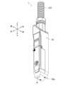
図16に示すように、洗浄載置部200は、本体部210と、印字ヘッド1の洗浄液を回収するための回収容器300とを備えている。本体部210は、上下方向に延びる背板部211を備えている。背板部211の上部には、印字ヘッド1を案内するとともに支持する案内支持部材230が設けられている。図17に示すように、案内支持部材230は、左右一対のレール部230a、230aと、支持部230bとを有している。レール部230a、230aは互いに左右方向に間隔をあけて設けられており、共に上下方向に延びるとともに、背板部211の前面から前側へ突出するように配置されている。レール部230a、230aの上端部は開放されている。支持部230bは、正規の位置に載置された印字ヘッド1を支持する部分であり、レール部230a、230aの間から前側へ向けて突出する突出部で構成されている。支持部230bはストッパ部と呼ぶこともできる。
As shown in FIG. 16, the
一方、図18に示すように、印字ヘッド1の筐体10の背面における上下方向中間部には、被案内部材18が設けられている。被案内部材18は、筐体10の背面から突出するように配設された板材等で構成されている。被案内部材18の左側には、洗浄載置部200の左側のレール部230aに嵌まるように形成された被案内部18aが左方向に突出するように形成されている。被案内部材18の右側には、洗浄載置部200の右側のレール部230aに嵌まるように形成された被案内部18aが右方向に突出するように形成されている。
On the other hand, as shown in FIG. 18, a guided
左右の被案内部18a、18aは上下方向に延びており、洗浄載置部200のレール部230a、230aの上端部から当該レール部230a、230a内に差し込むことが可能に形成されている。被案内部18a、18aはレール部230a、230a内に差し込まれた状態で当該レール部230a、230aによって上下方向に案内される。このとき、印字ヘッド1の移動方向は上下方向のみに規制され、洗浄載置部200に対して左右方向や前後方向には移動しないようになっている。
The left and right guided
被案内部材18の下端面は、洗浄載置部200の案内支持部材230に設けられている支持部230bの上面に当接する当接面18bとされている。当接面18bが図17に示す支持部230bの上面に当接するまで印字ヘッド1を洗浄載置部200に対して下方へ移動させることができる。言い換えると、被案内部材18の当接面18bの高さまたは支持部230bの上面の高さにより、洗浄載置部200に載置した状態の印字ヘッド1の高さを設定することができる。この実施形態では、洗浄載置部200に載置した状態の印字ヘッド1の高さは図15に示すように設定されており、この位置が正規の位置である。なお、図示しないが、レール部が印字ヘッド1に設けられていて、被案内部材が洗浄載置部200に設けられていてもよい。印字ヘッド1を正規の位置に位置決めする構造は上述した構造に限られるものではなく、印字ヘッド1を本体部210の一部によって正規の位置で支持可能な構成であればよい。
The lower end surface of the guided
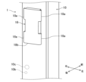
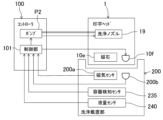
図16及び図19に示すように、洗浄載置部200の背板部211の内部には、磁石211aが設けられている。磁石211aは、磁力が背板部211を透過して前方へ作用するように配置されている。また、図19に示すように、背板部211の内部には、基板211bが設けられており、この基板211bには、赤外線通信を行うための赤外光を発する発光素子211cが実装されている。図20に示すように、発光素子211cは、コントローラ100の制御部101に接続されており、制御部101によって制御されるようになっている。図19に示すように、発光素子211cの発光面は前に向いている。背板部211には、発光素子211cの赤外光を透過する透過部材211dが設けられている。発光素子211cから照射された赤外光は透過部材211dを透過して背板部211の前方へ向けて照射される。
As shown in Figs. 16 and 19, a
一方、印字ヘッド1の筐体10の内部には、基板10aが設けられている。基板10aには、磁気センサ10bと、赤外線通信用の受光素子10cとが実装されている。磁気センサ10bは、所定閾値以上の磁力を検知したときに、そのことを電気信号に変換して出力するように構成された非接触の磁気センサであり、例えばホール素子等で構成することができる。磁気センサ10bは、印字ヘッド10が正規の位置にあるときに、洗浄載置部200の磁石211aと略同じ高さとなるように位置付けられている。磁石211aの前側において当該磁石211aと同じ高さが最も磁力の大きな所であり、この位置にあるときのみ、磁気センサ10bは、磁力検知信号を出力するように構成されている。したがって、例えば印字センサ1が正規の位置よりも上に載置されていた場合には、磁気センサ10bと磁石211aとの距離が遠くなるので、磁気センサ10bは磁力検知信号を出力しない。これを利用して印字ヘッド1が洗浄載置部200に載置されているか否か、正規の位置に載置されているか否かを検知できる。磁気センサ10bは、コントローラ100の制御部101に接続されており、制御部101に信号を出力するように構成されている。印字ヘッド1が洗浄載置部200に載置されているか否か、正規の位置に載置されているか否かの判定は、制御部101が行うようにしてもよい。
On the other hand, a
受光素子10cは、洗浄載置部200の発光素子211cから照射された赤外光を受光可能となるように、受光面が後側に向いている。印字ヘッド10が正規の位置にあるときにのみ、受光素子10cが発光素子211cの赤外光を受光できるように、受光素子10cの高さが設定されている。発光素子211cの赤外光は広範囲に拡散しないように指向性を狭めておくとともに、受光素子10cの指向性も狭めておくことで、印字ヘッド10が正規の位置にあるときにのみ、受光素子10cが発光素子211cの赤外光を受光可能になる。この通信の成立可否に基づいて、印字ヘッド1が洗浄載置部200に載置されているか否か、正規の位置に載置されているか否かを検知できる。受光素子10cは、コントローラ100の制御部101に接続されており、制御部101に信号を出力するように構成されている。印字ヘッド1が洗浄載置部200に載置されているか否か、正規の位置に載置されているか否かの判定は、通信の成立可否に基づいて、制御部101が行うようにしてもよい。なお、筐体10には、発光素子211cの赤外光を透過させる窓部10dが設けられている。
The
発光素子211c及び受光素子10cの位置は、図示した位置に限られるものではなく、印字ヘッド1が正規の位置に載置された状態でのみ、発光素子211cから照射された赤外光を受光素子10cが受光できる位置関係であればよい。同様に、磁石211a及び磁気センサ10bの位置は、図示した位置に限られるものではなく、印字ヘッド1が正規の位置に載置された状態でのみ、磁気センサ10bが磁力検知信号を出力する位置関係であればよい。
The positions of the light-emitting
上述したように、洗浄載置部200に印字ヘッド1が載置されなければ磁気センサ10bが磁力検知信号を出力しないので、磁気センサ10bは、洗浄載置部200に印字ヘッド1が載置されたことを検知する載置検知部に相当するものである。また、洗浄載置部200に対して印字ヘッド1が正規の位置に載置されていなければ磁気センサ10bが磁力検知信号を出力しないので、磁気センサ10bは、洗浄載置部200に対して印字ヘッド1が正規の位置に載置したことを検知することもできる。磁力検知信号は、印字ヘッド1の載置確認に基づく信号である。
As described above, the
また、洗浄載置部200に印字ヘッド1が載置されなければ受光素子10cが発光素子211cから照射された赤外光を受光することができないので、受光素子10cは、洗浄載置部200に印字ヘッド1が載置されたことを検知する載置検知部に相当するものである。また、洗浄載置部200に対して印字ヘッド1が正規の位置に載置されていなければ受光素子10cが発光素子211cから照射された赤外光を受光することができないので、受光素子10cは、洗浄載置部200に対して印字ヘッド1が正規の位置に載置したことを検知することもできる。また、発光素子211cと受光素子10cとが赤外線通信を行うことができなければ印字ヘッド1が載置されていないと推定できるので、制御部101は、受光素子10cの出力に基づいて、赤外線通信が可能な状態であるときには洗浄載置部200に印字ヘッド1が載置されていると検知することができる。同様に、洗浄載置部200に対して印字ヘッド1が正規の位置に載置されていなければ、発光素子211cと受光素子10cとが赤外線通信を行うことができないので、制御部101は、受光素子10cの出力に基づいて、赤外線通信が可能な状態であるときには洗浄載置部200に対して印字ヘッド1が正規の位置に載置されていると検知することができる。受光素子10cで取得された赤外線通信の信号は、印字ヘッド1の載置確認に基づく信号である。
In addition, if the
磁気センサ10bから出力される磁力検知信号及び受光素子10cで取得された赤外線通信の信号は、接続ケーブル107を介して印字ヘッド1からコントローラ100の制御部101に送られる。
The magnetic force detection signal output from the
載置検知部は、磁力検知信号や赤外線通信を利用したもの以外にも、例えば近接センサ、光電センサ、レーザセンサ等であってもよい。これらセンサを利用する場合、印字ヘッド1と洗浄載置部200との距離が所定距離以下となった場合に、印字ヘッド1が洗浄載置部200に対して載置した、または正規の位置に載置したことを検知できる。
In addition to using a magnetic detection signal or infrared communication, the placement detection unit may be, for example, a proximity sensor, a photoelectric sensor, a laser sensor, etc. When using these sensors, when the distance between the
この実施形態では、印字ヘッド1の載置確認に基づく信号として、磁力検知信号と赤外線通信との両方を出力可能構成しているが、これらのうち、一方のみ出力可能に構成してもよい。印字ヘッド1の載置確認に基づく信号を2種類以上出力することで、検知精度を向上させることができる。
In this embodiment, both a magnetic detection signal and infrared communication are configured to be output as signals based on confirmation that the
図16に示すように、背板部211には、上下方向中間部から前側へ向けて延びる底壁部212と、底壁部212から上方へ延びる周壁部213とが設けられており、底壁部212と周壁部213とによってコップ形状をなしている。図24に仮想線で示すように、周壁部213内に、正規の位置に載置されている印字ヘッド1の下側が挿入されるようになっている。この状態で印字ヘッド1の上側は周壁部213の上端部から上方へ突出している。また、印字ヘッド1の吐出口A(図5に示す)から下方に離れた所に底壁部212が位置している。印字ヘッド1の洗浄時に使用された溶剤は、主に印字ヘッド1の吐出口Aから漏れ出すことになるが、この吐出口Aから漏れ出した溶剤を底壁部212と周壁部213とによって受けることができるようになっている。底壁部212と周壁部213とは、説明の上で区別して示しているが、これらの境界が区別不能に一体化した形状であってもよく、要するに、印字ヘッド1の下側を収容可能な有底筒状に形成されていればよい。
As shown in FIG. 16, the
<回収容器300の取り付け構造>
図16に示すように、底壁部212には、印字ヘッド1の洗浄剤を回収するための回収容器300が取り付けられるようになっている。回収容器300は、例えば樹脂製ボトル等で構成することができ、内部の洗浄液量を外部から把握可能な透光性を有するものや、目盛りの付いたものを使用することができる。図21に示す変形例のように、回収容器300を底壁部212に直接取り付けることなく、例えばホースや配管部材等からなる管350を底壁部212に取り付け、この管350を介して洗浄液を別の回収容器(図示せず)に回収するようにしてもよい。この場合、回収容器は、コントローラ100に設けておくことができる。管350は回収容器の一部を構成する部材であってもよいし、洗浄載置部200の一部を構成する部材であってもよい。回収容器300の底壁部212への取付構造と、管350の底壁部212への取付構造とは、異なっていてもよいし、同じにすることもできる。以下、回収容器300の底壁部212への取付構造について詳細に説明する。
<Attachment structure of
As shown in FIG. 16, a
図22に示すように、回収容器300の上部には、円筒状の口部301が設けられている。口部301の外周面にはネジ山301aが形成されている。口部301の外周面には、ネジ山301aの下側にフランジ部301bが形成されている。回収容器300は、洗浄載置部200の一部を構成する部材とすることができる。
As shown in FIG. 22, a
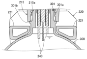
図24に示すように、底壁部212には、下方へ突出する筒状部212aが形成されている。筒状部212aの外径は、回収容器300の口部301の内径よりも小さく設定されている。筒状部212aの下端部は、図26に示すように回収容器300が底壁部212に取り付けられた状態で回収容器300の内部に挿入され、口部301の下端部よりも下に達するようになっている。
As shown in FIG. 24, the
図24に示すように、筒状部212a内には、印字ヘッド1の洗浄液が通過する通過孔212bが上下方向に延びるように形成されている。通過孔212bの上端部は、底壁部212の上面において前寄りの部分に開口している。また、通過孔212bの下端部は、筒状部212aの下端部において開口している。
As shown in FIG. 24, a through
図25にも示すように、底壁部212の上面には、導電性を有する金属製の板材からなる受け部材214が設けられている。受け部材214は、印字ヘッド1から漏れ出すインクを受ける部材であり等電位線と接続されている。印字ヘッド1から漏れ出すインクは、上記帯電電極13や偏向電極15により帯電していることがある。帯電したインクが受け部材214に触れると、インクの電荷を逃がすことができ、これにより、電荷の蓄積を抑制することができる。
As shown in FIG. 25, a receiving
受け部材214は、印字ヘッド1の吐出孔Aと対向するように配置されている。図24に示すように、受け部材214は、前側へ行くほど下に位置するように傾斜している。これにより、受け部材214で受けた洗浄液を受け部材214によって底壁部212の前側へ向けて案内して通過孔212bの上端開口部へ向けて流すことができる。
The receiving
受け部材214の前端部及び前後方向の中間部には、上方へ突出する突出板部214aが形成されている。受け部材214には、開口部214bも形成されている。突出板部214aや開口部214bは、必須なものではない。
A protruding
底壁部212の下面には、取付筒部215が下方へ突出するように形成されている。取付筒部215は、筒状部212aを囲むように、当該筒状部212aよりも大径となっている。取付筒部215の下端部は、筒状部212aの下端部よりも上に位置している。取付筒部215の内周面には、ネジ溝215aが形成されている。ネジ溝215aには、回収容器300のネジ山301aが螺合するようになっている。ネジ溝215aに回収容器300のネジ山301aを螺合させることにより、回収容器300を底壁部212に対して液漏れすることなく、取り付けることができる。図26に示すように、回収容器300の取付状態では、口部301が取付筒部215内に入り込むとともに、筒状部212aの下端部が回収容器300内に配置される。なお、図21に示す管350の場合もネジによって取り付けることができる。
The bottom surface of the
図16や図22に示すように、洗浄載置部200は、容器ホルダ220を備えている。容器ホルダ220は、本体部210の背板部211における底壁部212よりも下側部分に対して上下方向にスライド可能に取り付けられている。容器ホルダ220は、前方へ突出するように設けられた左右一対の係合突出部221、221を有している。係合突出部221、221間には、回収容器300の口部301を横方向に差し込むことが可能な隙間が形成されている。係合突出部221、221の左右方向の離間距離は、口部301のフランジ部301bの外径寸法よりも短く設定されており、回収容器300の口部301を係合突出部221、221間に横方向(図22に矢印Xで示す方向)から差し込むことにより、口部301のフランジ部301bを係合突出部221、221に対して上方から引っ掛けて保持することができるようになっている。
As shown in Figures 16 and 22, the
容器ホルダ220は、図22~図24に示す非装着位置と、図15、図16、図26等に示す装着完了位置とに切り替えることができるようになっている。容器ホルダ220は、周知のロック機構やストッパ等により、非装着位置から下方へ移動しないように停止させておくことができ、ユーザが非装着位置から装着完了位置に容易に切り替えることができる。洗浄載置部200は、容器ホルダ220を下方へ付勢するバネ等の付勢部材を備えていてもよい。
The
非装着位置は、容器ホルダ220の下降端位置であり、回収容器300を洗浄載置部200から取り外した位置である。非装着位置では、回収容器300の口部301を係合突出部221、221の間に差し込むこと、及び、係合突出部221、221の間に差し込んだ口部301を取り出すことが可能になっている。非装着位置にある容器ホルダ220を上方向、即ち縦方向に移動させていくことにより、装着完了位置に切り替えることができる。この装着完了位置では、容器ホルダ220が上昇端位置にあり、回収容器300の口部301を係合突出部221、221の間に差し込むことができなくなる。装着完了位置にある容器ホルダ220に保持されている回収容器300の口部301は取付筒部215に差し込まれるので、回収容器300を横方向に移動させることができなくなっている。
The non-attached position is the lower end position of the
容器ホルダ220を保持した状態の容器ホルダ220を装着位置にした後、回収容器300を、口部301のネジ山301aが取付筒部215のネジ溝215aに螺合する方向に回転させることで、ネジ山301aをネジ溝215aに螺合させて回収容器300を底壁部212に取り付けることができる。ネジ山301aをネジ溝215aに螺合させる過程で、回収容器300が上方へ徐々に移動していくが、この回収容器300の上方へ移動に伴って容器ホルダ220が当該回収容器300によって上方へ押し上げられ、図26に示す装着完了位置になる。この状態で、底壁部212に形成されている通過孔212bの下端開口が回収容器300内に臨むように配置されるので、印字ヘッド1から漏れ出した洗浄液の全量を回収容器300で回収することが可能になる。
After the
回収容器300を取り外す際には、取付時とは反対方向に回収容器300を回転させて口部301を取付筒部215から離脱させる。その後、容器ホルダ220を非装着位置に切り替えてから回収容器300を横方向に移動させて口部301を係合突出部221、221の間から抜くことができる。
When removing the
回収容器300の取付構造は上述した構造に限られるものではなく、例えば回収容器300の口部301を取付筒部215に圧入する構造であってもよい。図21に示す管350の場合も取付筒部215に圧入する構造であってもよい。また、容器ホルダ220は、回収容器300に取り付けるようにし、本体部210によって案内される構成のものであってもよい。また、容器ホルダ220を省略してもよい。
The attachment structure of the
<容器検知センサ235>
図24に示すように、洗浄載置部200は、回収容器300が取り付けられたことを検知する容器検知部としての容器検知センサ235を備えている。容器検知センサ235は、非接触の磁気センサを用いることができ、例えばホール素子等で構成することができる。すなわち、容器ホルダ220には、磁石231が設けられている。磁石231は、磁力が上方へ作用するように配置されている。一方、容器検知センサ235は、例えば底壁部212の内部に設けられており、磁石231の真上に配置されている。容器ホルダ220が非装着位置にあるときには、磁石231と容器検知センサ235とが最も離れることになり、磁石231の磁力を容器検知センサ235で検知することができず、容器検知センサ235は磁力検知信号を出力しない。図26に示すように、口部301のネジ山301aを取付筒部215のネジ溝215aに螺合させ、容器ホルダ220が装着完了位置にあるときには、容器ホルダ220が装着完了位置になるので、磁石231と容器検知センサ235とが最も接近することになる。このときにのみ、容器検知センサ235が磁力検知信号を出力するように構成されている。つまり、回収容器300が容器ホルダ220に保持されていたとしても、口部301が取付筒部215に接続されていないと、容器検知センサ235が磁力検知信号を出力しないように構成されている。容器検知センサ235は、コントローラ100の制御部101に接続されており、制御部101に信号を出力するように構成されている。
<
As shown in FIG. 24, the
図示しないが、磁石は、回収容器300に設けてもよい。この場合も回収容器300が装着完了位置になったときにのみ、容器検知センサ235がONになるので、回収容器300が取り付けられたことを容器検知センサ235で検知できる。容器ホルダ220を省略する場合には、磁石を回収容器300に設けることで回収容器300が取り付けられたことを検知できる。
Although not shown, a magnet may be provided on the
容器検知部は、磁力検知信号を利用したもの以外にも、例えば近接センサ、光電センサ、レーザセンサ、上述した赤外線通信を利用したもの等であってもよい。近接センサ、光電センサ、レーザセンサを利用する場合、回収容器300と底壁部212との距離が所定距離以下となった場合に、回収容器300が底壁部212に対して取り付けられたことを検知できる。赤外線通信の場合、回収容器300と底壁部212の一方に発光素子を設け、他方に受光素子を設けておき、発光素子と受光素子との通信可否に基づいて、回収容器300が底壁部212に対して取り付けられたこと判定できる。
In addition to using a magnetic detection signal, the container detection unit may be, for example, a proximity sensor, a photoelectric sensor, a laser sensor, or the above-mentioned infrared communication. When using a proximity sensor, a photoelectric sensor, or a laser sensor, it is possible to detect that the
容器ホルダ200を下方へ付勢する付勢部材を備えている場合には、回収容器300が取り付けられていない状態で容器ホルダ200だけが上昇端位置に配置されてしまうのを防止することができる。これにより、容器検知センサ235による誤検知を防止できる。
If a biasing member that biases the
<液量センサ240>
図23及び図27に示すように、洗浄載置部200は、回収容器300内の液量を検知する液量センサ240を備えている。液量センサ240は、2本の電極を備えている。これら電極は、底壁部212の下面から下方へ突出しており、取付状態にある回収容器300の口部301から当該口部301よりも下に達するように形成されている。液量センサ240による測定原理は、インクを含んだ洗浄液が導体であることを利用したものであり、2本の電極間のインピーダンスを測定し、そのインピーダンス変化に基づいて液量が所定以上であるか否かを検知することができる。例えば、洗浄液の液面が回収容器300内の口部301近傍に達したときに、当該洗浄液に接触するように両電極の下端部の位置を設定しておくことができる。この場合、2本の電極間のインピーダンスが急に変化した場合には、洗浄液が満量にあるということであり、満量を検知するセンサとして液量センサ240を利用することができる。また、液量センサ240は、洗浄液が溢れる直前の状態を検知する溢れ検知センサと呼ぶこともできる。液量センサ240は、コントローラ100の制御部101に接続されており、制御部101に信号を出力するように構成されている。
<
As shown in FIG. 23 and FIG. 27, the
純粋な洗浄液が非導体である場合には、洗浄動作前に少量のインクをノズル12から吐出させる制御を行うことにより、回収容器300内の洗浄液にインクを必ず含ませることができる。これにより、上述した検知手法を利用することができる。
If the pure cleaning liquid is non-conductive, ink can be ensured in the cleaning liquid in the
液量センサ240の構成は上述した構成に限られるものではなく、回収容器300内の洗浄液の液面の高さ、回収容器300内の洗浄液の量や重さを直接または間接的に取得できるセンサであれば、どのようなセンサであってもよい。洗浄液の液面の高さを取得するセンサの一例としては、例えば変位センサ等がある。変位センサで液量を検知する場合、回収容器300の有無を当該変位センサによって検知することもできる。
The configuration of the
また、液量センサ240は、例えばフロートセンサ、静電容量式レベルセンサ、光電センサ等であってもよい。
The
<メンテナンス実行処理>
図28は、メンテナンスを実行する際に行われる処理を例示するフローチャートである。メンテナンスとは、例えば洗浄動作である。以下の判定や制御は、コントローラ100の制御部101によって行うことができる。ユーザが印字ヘッド1を洗浄載置部200にセットすると、ステップSE1で印字ヘッド1が洗浄載置部200に対して正規の位置に載置されたか否かを判定する。この判定には、磁気センサ10bの出力信号を用いることができる。磁気センサ10bから磁力検知信号が出力されていれば、印字ヘッド1が洗浄載置部200の正規の位置に載置されているのでYESと判定する一方、磁気センサ10bから磁力検知信号が出力されていなければ、印字ヘッド1が洗浄載置部200の正規の位置に載置されていないのでNOと判定される。ステップSE1では、発光素子211cと受光素子10cとの赤外線通信が成立した否かに基づいて判定することもでき、この場合、発光素子211cと受光素子10cとの赤外線通信が成立すればYESと判定する一方、発光素子211cと受光素子10cとの赤外線通信が成立しなければNOと判定する。また、ステップSE1では、磁気センサ10bの信号と、赤外線通信との2つに基づいて判定することもでき、磁気センサ10bから磁力検知信号が出力されていないか、赤外線通信が成立していなければ、NOと判定する。ステップSE1でYESと判定された場合にはステップSE4に進む。
<Maintenance execution process>
FIG. 28 is a flow chart illustrating the process performed when performing maintenance. Maintenance is, for example, a cleaning operation. The following judgments and controls can be performed by the
一方、ステップSE1でNOと判定されてステップSE2に進むと、印字ヘッド1を正規の位置に載置するようにメッセージを出す。メッセージは、例えば図2に示す表示部103aに表示させることができる。これにより、ユーザに印字ヘッド1の位置確認を促すことができる。その後、ステップSE3に進み、ステップSE1と同様な判定を行い、NOと判定された場合にはステップSE2に進んで再度メッセージを出す。ステップSE3でYESと判定されて印字ヘッド1が正規の位置に載置されると、ステップSE4に進む。
On the other hand, if the determination in step SE1 is NO and the process proceeds to step SE2, a message is issued to place the
ステップSE4では、容器検知センサ235がONであるか否か、即ち、回収容器300が取り付けられているか否かを判定する。回収容器300が取り付けられると、容器検知センサ235が磁力検知信号を出力する(容器検知センサ235がONになる)ので、この場合には、YESと判定とされてステップSE7に進む。一方、回収容器300が取り付けられていない場合には、ステップSE4でNOと判定されてステップSE5に進み、回収容器300を取り付けるようにメッセージを出す。メッセージは、例えば図2に示す表示部103aに表示させることができる。これにより、ユーザに回収容器300を取り付けるように促すことができる。その後、ステップSE6に進み、ステップSE4と同様な判定を行い、NOと判定された場合にはステップSE5に進んで再度メッセージを出す。ステップSE6でYESと判定されて回収容器300が取り付けられると、ステップSE7に進む。
In step SE4, it is determined whether the
ステップSE7では、液量センサがONであるか否か、即ち、回収容器300が満量または満量に近い状態であるか否かを判定する。回収容器300が満量または満量に近い状態でない場合には、液量センサ240がOFFになるので、この場合には、YESと判定とされてステップSE10に進む。一方、回収容器300が満量または満量に近い状態である場合には、ステップSE7でNOと判定されてステップSE8に進み、回収容器300内の洗浄液を廃棄するようにメッセージを出す。メッセージは、例えば図2に示す表示部103aに表示させることができる。これにより、ユーザに回収容器300内の廃液を促すことができる。その後、ステップSE9に進み、ステップSE7と同様な判定を行い、NOと判定された場合にはステップSE8に進んで再度メッセージを出す。ステップSE9でYESと判定されて廃液されると、ステップSE10に進む。ステップSE10では、洗浄動作の許可信号を出力して各種メンテナンスを実行可能にする。
In step SE7, it is determined whether the liquid level sensor is ON, that is, whether the
この例では、コントローラ100の洗浄動作部101aは、ステップSE1またSE3において、載置検知部である磁気センサ10bから送られた印字ヘッド1の載置確認に基づく信号(磁力検知信号)を受信した場合に、洗浄載置部200に載置された印字ヘッド1の洗浄動作を行い、それ以外の場合には洗浄動作を禁止する。また、コントローラ100の洗浄動作部101aは、ステップSE1またSE3において、受光素子10cで取得された赤外線通信の信号(印字ヘッド1の載置確認に基づく信号)を受信した場合に、洗浄載置部200に載置された印字ヘッド1の洗浄動作を行い、それ以外の場合には洗浄動作を禁止する。つまり、ステップSE1またはSE3では、洗浄動作部101aが印字ヘッド1の載置確認に基づく信号を受信していない時には、印字ヘッド1の洗浄動作を禁止することができる。
In this example, in step SE1 or SE3, the
<接続確認処理>
上述した図28に示すフローチャートの処理では、印字ヘッド1の載置確認に基づく信号を受信すれば、回収容器300の検知及び液量検知を行い、それらが問題なければ、洗浄動作部101aが印字ヘッド1の洗浄動作を行うことになる。自動印字システムSが1台のみ導入されている現場であれば、洗浄載置台200に載置される印字ヘッド1はその自動印字システムSのものであるため、図28に示すフローチャートの処理で特に問題は生じない。
<Connection confirmation process>
In the processing of the flowchart shown in Figure 28 described above, when a signal based on confirmation of the placement of the
しかし、図29に示すように、複数台の自動印字システムSが1つの現場に導入されている場合がある。この例では、第1のコントローラA、第1の印字ヘッドA及び第1の洗浄載置部Aで1つの自動印字システムSが構成され、第2のコントローラB、第2の印字ヘッドB及び第2の洗浄載置部Bで別の自動印字システムSが構成されている。第1及び第2の印字ヘッドA、Bの構造及び形状は同じで、第1及び第2の洗浄載置部A、Bの構造及び形状も同じであるため、図29に示すように、ユーザが第1のコントローラAに接続された第1の印字ヘッドAを洗浄するために第1の洗浄載置部Aに載置したつもりが、誤って、第2のコントローラBに接続された第2の印字ヘッドBを第1の洗浄部Aに載置した場合、第1の印字ヘッドAが洗浄載置部A、Bのいずれにも載置されていない状態になる。この状態で自動洗浄が行われると、第1の印字ヘッドAから漏れ出した洗浄液を受ける物がないので、洗浄液が周囲環境を汚染したり、揮発して好ましくない環境になり得るおそれがある。つまり、図28に示すフローチャートの処理では、誤った載置がなされた場合であるにも関わらず、印字ヘッド1の洗浄が行われてしまう可能性がある。
However, as shown in FIG. 29, there are cases where multiple automatic printing systems S are installed at one site. In this example, one automatic printing system S is configured with a first controller A, a first print head A, and a first cleaning placement unit A, and another automatic printing system S is configured with a second controller B, a second print head B, and a second cleaning placement unit B. The first and second print heads A and B have the same structure and shape, and the first and second cleaning placement units A and B also have the same structure and shape. Therefore, as shown in FIG. 29, if a user intends to place the first print head A connected to the first controller A on the first cleaning placement unit A to clean it, but mistakenly places the second print head B connected to the second controller B on the first cleaning unit A, the first print head A will not be placed on either of the cleaning placement units A or B. If automatic cleaning were to be performed in this state, there would be nothing to receive the cleaning fluid leaking from the first print head A, and the cleaning fluid could contaminate the surrounding environment or evaporate, creating an undesirable environment. In other words, in the process of the flowchart shown in Figure 28, even if the
この場合、図30に示すフローチャートの処理を行うことができる。ステップSF1では、印字ヘッド1の洗浄載置部200への載置を検知する。これは磁気センサ10bから出力される磁力検知信号または受光素子10cで取得された赤外線通信の信号に基づいて検知できる。その後、ステップSF2では、コントローラ100の洗浄動作部101aが、印字ヘッド1が載置されていることを確認する。
In this case, the process of the flowchart shown in Figure 30 can be performed. In step SF1, placement of the
ステップSF3では、コントローラ100が有する識別情報であるシリアルNo.を洗浄載置部200に送信する。コントローラ100が有する識別情報は、シリアルNo.に限られるものではなく、コントローラ100に固有の情報とすることができ、例えば数字、文字、記号等で構成することができ、数字、文字、記号等のうち、任意の1つのみで構成されていてもよいし、任意の2つ以上を組み合わせて構成されていてもよい。コントローラ100が有する識別情報は、乱数であってもよい。
In step SF3, the serial number, which is identification information possessed by the
ステップSF4では、コントローラ100から送信されたシリアルNo.を洗浄載置部200が受信する。ステップSF5では、洗浄載置部200がコントローラ100から送信されたシリアルNo.を印字ヘッド1に送信する。このとき、発光素子211cと受光素子10cによる赤外線通信によって送信することができる。ステップSF6では、洗浄載置部200から送信されたコントローラ100のシリアルNo.を印字ヘッド1が受信する。ステップSF7では洗浄載置部200から送信されたコントローラ100のシリアルNo.をコントローラ100に送信する。ステップSF8では、印字ヘッド1から送信されたシリアルNo.をコントローラ100が受信する。ステップSF9では、コントローラ100の制御部101は、印字ヘッド1から送信されたコントローラ100のシリアルNo.が、ステップSF3でコントローラ100が送信したシリアルNo.と一致しているか否かを判定する。この処理は、洗浄載置部200に載置された印字ヘッド1がコントローラ100に接続されたものであるか否かの認証処理である。両者が一致していないということは、このコントローラ100に接続された印字ヘッド1ではないということなので、以下の処理には進まず、ステップSF3に戻り、ステップSF3~SF9の処理を繰り返す。所定回数繰り返してもステップSF9で不一致と判定される場合には、このフローを中断してユーザに報知するか、エラー表示を行う。
In step SF4, the
一方、ステップSF9において、印字ヘッド1から送信されたコントローラ100のシリアルNo.が、ステップSF3でコントローラ100が送信したシリアルNo.と一致していると判定された場合には、ステップSF10に進む。ステップSF10では、センサ状態の出力要求を洗浄載置部200に対して行う。ステップSF11では、洗浄載置部200がセンサ状態、即ち、容器検知センサ235及び液量センサ240の状態をコントローラ100の洗浄動作部101aに送信する。ステップSF12では洗浄動作部101aがセンサ状態を受信する。ステップSF13では、メンテナンスが実行可能か否かを確認する。
On the other hand, if it is determined in step SF9 that the serial number of the
確認時のフローチャートは図31に示す。センサ状態の確認開始後、ステップSG1では、磁気センサ10bの状態を確認する。磁気センサ10bがON、即ち磁力検知信号を出力していればステップSG2に進む一方、磁気センサ10bがOFF、即ち磁力検知信号を出力していなければステップSG4に進む。磁気センサ10bの代わりに、受光素子10cで取得された赤外線通信の信号を用いることができる。
The flowchart for confirmation is shown in FIG. 31. After starting to check the sensor state, in step SG1, the state of the
ステップSG2では、容器検知センサ235の状態を確認する。容器検知センサ235がON、即ち回収容器300が取り付けられていればステップSG3に進む一方、容器検知センサ235がOFF、即ち回収容器300が取り付けられていなければステップSG4に進む。ステップSG3では、液量センサ240の状態を確認する。液量センサ240がOFF、即ち回収容器300内の洗浄剤の量が満量よりも少なければ、始めのステップに戻ってメンテナンス実行可能とする一方、液量センサ240がON、即ち回収容器300内の洗浄剤の量が満量であれば、ステップSG4に進む。ステップSG4では、メンテナンスを禁止するので、洗浄動作部101aが洗浄動作を許可しない。ステップSG4に進まない限りは、洗浄動作部101aが洗浄動作を許可する。したがって、図30に示すフローチャートのステップSF13において「可能」と判定されてステップSF14に進む。図31に示すフローチャートのステップSG4に進むと、図30に示すフローチャートのステップSF13で「不可能」と判定されてステップSF10に戻る。
In step SG2, the state of the
ステップSF14では洗浄動作部101aがメンテナンスを実行する。具体的には、コントローラ100の溶剤ポンプP2を作動させるとともに、溶剤噴射バルブを開く。洗浄動作中は、図31に示すフローチャートが繰り返し実行されており、ステップSG4に進んだ時点で洗浄動作部101aは洗浄動作を中断する。
In step SF14, the
印字ヘッド1は、ステップSF1で印字ヘッド1の載置確認に基づく信号を送り、ステップSF7で信号ラインを介して予め取得したコントローラ100の識別情報を、コントローラ100に送るように構成されている。従って、印字ヘッド1が載置されただけでは洗浄動作が実行されることはなく、ステップSF9でコントローラ100の識別情報が一致しなければ洗浄動作が実行されない。例えば、図29に示すように第2の印字ヘッドBが第1の洗浄載置部Aに載置されている場合には、第1のコントローラAから送信された識別情報は第2のコントローラBが受信することになり、その結果、第1のコントローラAには送信されないので、第1のコントローラAが洗浄動作を行うことはない。よって、第1の印字ヘッドAから洗浄液が漏れ出さないようにすることができる。
The
また、ステップSF1で印字ヘッド1の載置確認に基づく信号を送る際に、印字ヘッド1の識別情報もコントローラ100へ送るように構成することもできる。コントローラ100に接続されている印字ヘッド1に固有の識別番号等からなる識別情報を付与している場合に、印字ヘッド1の識別情報をコントローラ100で確認することで、当該コントローラ100に接続されている印字ヘッド1であるか否かを確認することができる。印字ヘッド1の載置確認が行われ、かつ、当該コントローラ100に接続されている印字ヘッド1であると確認された場合に、印字ヘッド1の洗浄動作を許可するように、洗浄動作部101aを構成することができる。
The
<変形例1>
図32は、実施形態の変形例1に係る簡易ブロック図である。変形例1では、印字ヘッド1に、磁石10e及び発光素子10fを設けており、発光素子10fはコントローラ100の制御部101によって制御される。載置洗浄部200には、磁気センサ200a及び受光素子200bを設けている。印字ヘッド1の磁石10eの磁力を載置洗浄部200の磁気センサ200aが検知可能になっている。印字ヘッド1の発光素子10fが照射した赤外光を載置洗浄部200の受光素子200bが受光可能になっている。磁気センサ200a及び受光素子200bは、コントローラ100の制御部101に接続されている。この変形例1では、赤外線通信及び磁気センサ200aによる検知結果に基づいて印字ヘッド10の載置確認や正規の位置にあるか否かを正確に判定できる。
<
32 is a simplified block diagram according to a first modified example of the embodiment. In the first modified example, the
図33は、実施形態の変形例1に係る処理を例示するフローチャートである。ステップSH1では、洗浄載置部200が、印字ヘッド1の洗浄載置部200への載置を検知する。これは磁気センサ200aから出力された磁力検知信号または受光素子200bで取得された赤外線通信の信号に基づいて検知できる。その後、ステップSH2では、コントローラ100の洗浄動作部101aが、印字ヘッド1が載置されていることを確認する。
Figure 33 is a flow chart illustrating the process according to the first modified example of the embodiment. In step SH1, the
ステップSH3では、コントローラ100が有する識別情報であるシリアルNo.を印字ヘッド1に送信する。ステップSH4では、コントローラ100から送信されたシリアルNo.を印字ヘッド1が受信する。ステップSH5では、印字ヘッド1がコントローラ100から送信されたシリアルNo.を洗浄載置部200に送信する。このとき、発光素子10fと受光素子200bによる赤外線通信によって送信することができる。ステップSH6では、印字ヘッド1から送信されたコントローラ100のシリアルNo.を洗浄載置部200が受信する。ステップSH7では、印字ヘッド1から送信されたコントローラ100のシリアルNo.をコントローラ100に送信する。ステップSH8では、洗浄載置部200から送信されたシリアルNo.をコントローラ100が受信する。ステップSH9~SH16は、それぞれ図30に示すフローチャートのステップSF9~SF16と同じである。これにより、ステップSH9でシリアルNo.が一致しなければ洗浄動作が実行されないので、図29に示すような状態で第1の印字ヘッドAが洗浄されることはない。
In step SH3, the serial number, which is the identification information possessed by the
<変形例2>
図34は、実施形態の変形例2に係る簡易ブロック図である。変形例2では、印字ヘッド1に、受光素子10cだけでなく発光素子10fを設けている。発光素子10fはコントローラ100の制御部101によって制御される。洗浄載置部200には、発光素子211cだけでなく、受光素子200bも設けられている。さらに、洗浄載置部200には、制御部200cが設けられている。制御部200cには、容器検知センサ235、液量センサ240、受光素子200b及び発光素子211cが接続されている。容器検知センサ235及び液量センサ240の検知結果と、受光素子200bが受信した情報とは、制御部200cで処理された後、発光素子211cによって印字ヘッド1側に送信されて、受光素子10cで受信される。印字ヘッド1で受信された情報は、コントローラ100の制御部101に送信される。この変形例2では、コントローラ100が洗浄載置部200に電力を供給するだけであり、コントローラ100と洗浄載置部200との直接の通信は行わない。洗浄載置部200にはバッテリが内蔵されていてもよい。
<
FIG. 34 is a simplified block diagram according to a second modified example of the embodiment. In the second modified example, the
図35は、実施形態の変形例2に係る処理を例示するフローチャートである。ステップSI1では、印字ヘッド1の洗浄載置部200への載置を当該印字ヘッド1が検知する。これは磁気センサ10bから出力された磁力検知信号または受光素子10cで取得された赤外線通信の信号に基づいて検知できる。その後、ステップSI2では、コントローラ100の洗浄動作部101aが、印字ヘッド1が載置されていることを確認する。
Figure 35 is a flow chart illustrating the process according to the second modified embodiment. In step SI1, the
ステップSI3では、センサ状態の出力要求を印字ヘッド1に対して行う。ステップSI4では、印字ヘッド1がセンサ状態の出力要求を洗浄載置部200に対して行う。ステップSI5では、印字ヘッド1から送信されたセンサ状態の出力要求を洗浄載置部200が受信する。ステップSI6では、洗浄載置部200が、容器検知センサ235及び液量センサ240の状態を印字ヘッド1に送信する。ステップSI7では、印字ヘッド1が洗浄載置部200から送信された容器検知センサ235及び液量センサ240の状態を受信する。
In step SI3, a sensor status output request is made to the
ステップSI8では、容器検知センサ235及び液量センサ240の状態を受信し、メンテナンスが実行可能か否かを確認する。「可能」であればステップSI9に進んだ後、ステップSI10、SI11に進み、洗浄動作を実行する。「不可能」であれば、ステップSI13に戻る。
In step SI8, the status of the
この変形例2では、容器検知センサ235及び液量センサ240の状態を、印字ヘッド1を経由して取得することができるので、図29に示すような誤った載置であっても、器検知センサ235及び液量センサ240の状態に基づいて制御を行うことができ、安全性を担保できる。
In this
<変形例3>
図36は、実施形態の変形例3に係る簡易ブロック図である。変形例3では、洗浄載置部200に、制御部200cが設けられている。制御部200cには、磁気センサ211a、容器検知センサ235、液量センサ240及び発光素子211cが接続されている。磁気センサ211a、容器検知センサ235及び液量センサ240の検知結果は、制御部200cで処理された後、発光素子211cによって印字ヘッド1側に送信されて、受光素子10cで受信される。印字ヘッド1で受信された情報は、コントローラ100の制御部101に送信される。この変形例3では、コントローラ100が洗浄載置部200に電力を供給するだけであり、コントローラ100と洗浄載置部200との直接の通信は行わない。
<Modification 3>
36 is a simplified block diagram according to a third modification of the embodiment. In the third modification, the
図37は、実施形態の変形例3に係る処理を例示するフローチャートである。ステップSJ1では、洗浄載置部200が、印字ヘッド1の洗浄載置部200への載置を検知する。これは磁気センサ211aから出力された磁力検知信号に基づいて検知できる。その後、ステップSJ2では、洗浄載置部200が容器検知センサ235及び液量センサ240の状態を印字ヘッド1に対して送信する。ステップSJ3では、洗浄載置部200から送信されたセンサ状態を印字ヘッド1がコントローラ100に送信する。
Figure 37 is a flow chart illustrating a process according to the third modified example of the embodiment. In step SJ1, the
ステップSJ4では、容器検知センサ235及び液量センサ240の状態を受信し、メンテナンスが実行可能か否かを確認する。「可能」であればステップSJ5に進んだ後、ステップSJ6、SJ7に進み、洗浄動作を実行する。「不可能」であれば、このフローを終了する。
In step SJ4, the status of the
変形例3では、コントローラ100からのコマンドレスポンス方式ではなく、洗浄載置部200が載置検知すると、センサ状態を一方向的に出力する。これにより、赤外線通信部を一方向通信で構成すればよいので、発光素子及び受光素子の個数を削減できる。
In the third modification, instead of using a command response method from the
<変形例4>
図38は、実施形態の変形例4に係る簡易ブロック図である。変形例4では、洗浄載置部200に、洗浄剤ノズル200d及び洗浄剤ポンプP5を設けるとともに、制御部200cも設けている。洗浄剤ポンプP5には、図示しない洗浄剤タンクまたは洗浄剤カートリッジが接続されている。制御部200cには、磁気センサ211a、容器検知センサ235、液量センサ240及び発光素子211cが接続されている。磁気センサ211a、容器検知センサ235及び液量センサ240の検知結果は、制御部200cで処理され、制御部200cが洗浄剤ノズル200dの電磁弁(洗浄剤噴射バルブ)及び洗浄剤ポンプP5を制御して、洗浄動作を実行することができる。洗浄剤ノズル200dは、図24に示す洗浄剤ノズル360のように配設することができる。この変形例4では、洗浄剤としてコントローラ100内の溶剤を利用しなくてもよいので、水や水溶性洗浄剤を使用することができる。
<Modification 4>
FIG. 38 is a simplified block diagram according to the fourth modification of the embodiment. In the fourth modification, the
図39は、実施形態の変形例3に係る処理を例示するフローチャートである。ステップSK1では、洗浄載置部200が、印字ヘッド1の洗浄載置部200への載置を検知する。これは磁気センサ211aから出力された磁力検知信号に基づいて検知できる。その後、ステップSK2では、コントローラ100の洗浄動作部101aが、印字ヘッド1が載置されていることを確認する。
Figure 39 is a flow chart illustrating the process according to the third modified example of the embodiment. In step SK1, the
ステップSK3では、コントローラ100が有する識別情報であるシリアルNo.を洗浄載置部200に送信する。ステップSK4では、コントローラ100から送信されたシリアルNo.を洗浄載置部200が受信する。ステップSK5では、洗浄載置部200がコントローラ100から送信されたシリアルNo.を印字ヘッド1に送信する。ステップSK6では、洗浄載置部200から送信されたコントローラ100のシリアルNo.を印字ヘッド1が受信する。ステップSK7では、浄載置部200から送信されたコントローラ100のシリアルNo.をコントローラ100に送信する。ステップSK8では、印字ヘッド1から送信されたシリアルNo.をコントローラ100が受信する。ステップSK9では、印字ヘッド1から送信されたコントローラ100のシリアルNo.が、ステップSK3でコントローラ100が送信したシリアルNo.と一致しているか否かを判定する。両者が一致していない場合には、ステップSK3に戻る。
In step SK3, the serial number, which is identification information possessed by the
一方、ステップSK9において、印字ヘッド1から送信されたコントローラ100のシリアルNo.が、ステップSK3でコントローラ100が送信したシリアルNo.と一致していると判定された場合には、ステップSK10に進む。ステップSK10では、メンテナンス実行要求を洗浄載置部200に送信する。ステップSK11では、容器検知センサ235及び液量センサ240の状態を制御部200cに送信する。ステップSK12では、制御部200cが、容器検知センサ235及び液量センサ240の状態に基づいてメンテナンスを実行可能か否か判定する。「不可能」である場合には、ステップSK10に戻る。「可能」である場合には、ステップSK13に進んだ後、ステップSK14でポンプP5を作動させ、ステップSK15で洗浄剤噴射バルブを開く。
On the other hand, if it is determined in step SK9 that the serial number of the
<変形例5>
図40は、実施形態の変形例5に係る簡易ブロック図である。変形例5では、印字ヘッド1がAND回路を有しており、AND回路によって洗浄ノズル19の電磁弁を制御することができるようになっている。AND回路には、制御部101からの制御信号が入力されるとともに、磁気センサ10bの出力信号が入力されるようになっている。制御部101からの制御信号が洗浄動作許可信号であり、かつ、磁気センサ10bの磁力検知信号が入力されると、洗浄ノズル19の電磁弁を閉から開に切り替えて洗浄動作を行うことができる。
<Modification 5>
40 is a simplified block diagram according to a fifth modification of the embodiment. In the fifth modification, the
図41は、実施形態の変形例3に係る処理を例示するフローチャートである。ステップSL1では、コントローラ100がシリアルNo.を洗浄載置部200に送信する。ステップSL2では、コントローラ100から送信されたシリアルNo.を洗浄載置部200が受信する。ステップSL3は、コントローラ100から受信したシリアルNo.を洗浄載置部200が印字ヘッド1に送信する。ステップSL4では、洗浄載置部200から送信されたシリアルNo.を印字ヘッド1が受信する。ステップSL5では、洗浄載置部200から受信したシリアルNo.を印字ヘッド1がコントローラ100に送信する。ステップSL6では、印字ヘッド1から送信されたシリアルNo.をコントローラ100が受信する。
Figure 41 is a flow chart illustrating a process according to the third modified example of the embodiment. In step SL1, the
ステップSL7では、印字ヘッド1から送信されたコントローラ100のシリアルNo.が、ステップSL1でコントローラ100が送信したシリアルNo.と一致しているか否かを判定する。両者が一致していない場合には、ステップSL1に戻る。一致していれば、ステップSL8に進み、センサ状態の出力要求を洗浄載置部200に対して行う。ステップSL9では、洗浄載置部200が容器検知センサ235及び液量センサ240の状態をコントローラ100に送信する。ステップSL10では、容器検知センサ235及び液量センサ240の状態を受信し、ステップSL11では、メンテナンスが実行可能か否かを確認する。「不可能」であればステップSL8に進み、「可能」であればステップSL12に進んでメンテナンスを実行する。この場合、ステップSL14でポンプを作動させる。一方、印字ヘッド1は、磁気センサ10bの出力信号に基づいて印字ヘッド1の載置検知の結果を取得し、この載置検知の信号と、メンテナンス実行許可信号とのAND条件が成立した場合にのみ、ステップSL15に進んで溶剤噴射バルブを開く。
In step SL7, it is determined whether the serial number of the
この変形例5では、容器検知センサ235、液量センサ240及び載置検知の信号のANDをもってバルブを制御することができ、制御部101には、載置検知の信号が伝達されない。この変形例5の洗浄制御部は、印字ヘッド1のAND回路を含むように構成することができる。
In this modification 5, the valve can be controlled by the AND of the signals from the
<スリープモード>
この実施形態では、自動印字システムSの稼働停止期間が長期間に亘る場合に、インクの固着による不具合を起こりにくくするために自動洗浄を定期的に行うスリープモードを実行可能に構成されている。図2に示すように、コントローラ100の制御部101は、モード動作部101bを備えている。モード動作部101bは、載置検知部(磁気センサ10bや受光素子10c等)により印字ヘッド1が洗浄載置部200に載置されたことを検知した場合に、外部電力が供給されたインクジェット記録装置Iの稼働停止中に所定間隔で自動的に印字ヘッド1の洗浄動作を行うためのスリープモードを動作させる部分である。スリープモードを動作させるためには、図2に示すように例えば商用電源700等からインクジェット記録装置Iに電力を供給しておく。
<Sleep mode>
In this embodiment, when the automatic printing system S is out of operation for a long period of time, the system is configured to be able to execute a sleep mode in which automatic cleaning is performed periodically to prevent problems caused by ink adhesion. As shown in Fig. 2, the
図42は、スリープモードの動作の一例を示すフローチャートである。立下げ後に、印字ヘッド1を洗浄載置部200に載置されていることを検知すると、このフローが開始される。フローが開始されると、モード動作部101bは、図43に示すメンテナンス用ユーザインターフェース400を生成し、図2に示す表示部103aに表示させる。メンテナンス開始ユーザインターフェース400には、スリープモードを開始する際に操作する開始ボタン400aと、スリープモードに関する説明文や説明図を表示する表示領域400bとが設けられている。図42のステップSM1において開始ボタン400aが押されると、モード動作部101bがそのことを検知し、スリープモードを動作させる。また、モード動作部101bは、図44に示す状態表示ユーザインターフェース401を生成し、図2に示す表示部103aに表示させる。状態表示ユーザインターフェース401には、スリープモードを解除(終了)する際に操作する解除ボタン401aと、インク残量等を表示する状態表示領域401bと、説明文や説明図を表示する表示領域401cとが設けられている。スリープモード中は、状態表示ユーザインターフェース401を表示させておくことができる。
Figure 42 is a flowchart showing an example of the operation of the sleep mode. After power-down, this flow is started when it is detected that the
図42のステップSM2では、数週間から数ヶ月以上に亘って長期間放置された場合を示している。この間に、洗浄動作部101aは、インクジェット記録装置Iを自動的に立ち上げて溶剤供給部105によって溶剤をノズル12に供給して当該ノズル12から吐出させる洗浄動作を行う。洗浄動作は、溶剤をノズル12に供給して当該ノズル12から吐出させる洗浄動作以外にも、例えば、溶剤を洗浄ノズル19から噴射する洗浄動作であってもよいし、インクをインク供給部104からノズルに供給して当該ノズルから吐出させる洗浄動作であってもよい。これら複数の洗浄動作のうち、2以上を行うようにすることもできる。洗浄用のノズルは洗浄ノズル19に限られるものではなく、例えば図24に仮想線で示すように、洗浄載置部200に設けられた洗浄剤ノズル360であってもよい。洗浄剤ノズル360には、コントローラ100から洗浄ノズル19と同様に洗浄剤を供給することができる。洗浄剤ノズル360は、ノズル12や帯電電極13等に洗浄剤を噴射することができる。
Step SM2 in FIG. 42 shows a case where the inkjet recording apparatus I is left for a long period of time, from several weeks to several months. During this time, the
図2に示すように、コントローラ100の制御部101は、インクジェット記録装置Iがスリープモード動作中である時間を計測する時間計測部101cを備えている。この時間計測部101cは、いわゆるタイマーであり、図43に示すメンテナンス用ユーザインターフェース400の開始ボタン400aが押された時から計時を開始するように構成することができ、また、モード動作部101bがスリープモードを動作させた時から計時を開始するように構成することができる。
As shown in FIG. 2, the
洗浄動作部101aは、モード動作部101bがスリープモードを動作させたことを検知したとき、時間計測部101cにより計測されたスリープモード動作中の時間を取得する。時間計測部101cにより計測されたスリープモード動作中の時間が所定時間に達した場合、洗浄動作部101aが洗浄動作を行う。
When the
図42に示すステップSM3において、図44に示す状態表示ユーザインターフェース401の解除ボタン401aが押されると、モード動作部101bがそのことを検知し、スリープモードを解除する。制御部101は、モード動作部101bがスリープモードを解除したことを検知すると、ステップSM4の立上処理を実行し、その後、ステップSM5の印字処理を実行する。
In step SM3 shown in FIG. 42, when the release button 401a of the status display user interface 401 shown in FIG. 44 is pressed, the
上記の例では、洗浄載置部200側の異常を確認することなく、スリープモードを動作させた場合について説明したが、これに限らず、洗浄載置部200側の異常を確認しながらスリープモードを動作させることもできる。
In the above example, the case where the sleep mode is operated without checking for abnormalities on the
図45は、洗浄載置部200側の異常を確認しながらスリープモードを動作させる場合のフローチャートである。ステップSN1において図43に示す開始ボタン400aが押されると、モード動作部101bがそのことを検知し、スリープモードを動作させる。ステップSN2では、時間計測部101cが計時を開始するとともに、インクジェット記録装置Iが立下げられた日時に「7日」を加える処理を行う。この「7日」は、洗浄動作が必要であると判断される期間であり、「7日」に限られるものではない。日数の代わりに時間を加える処理を行ってもよい。
Figure 45 is a flow chart for operating the sleep mode while checking for abnormalities on the
ステップSN3で待った後、ステップSN4に進み、所定時間(この例では上記7日間)経過したか否かを判定する。ステップSN4でNOと判定されて7日間経過していない場合にはステップSN3に進んで待ち、再びステップSN4の判定を行う。ステップSN4でYESと判定されて、インクジェット記録装置Iが立下げられてから7日間経過すると、ステップSN5に進み、エラー解除処理を行う。エラーについては後述する。 After waiting in step SN3, the process proceeds to step SN4 to determine whether a predetermined time has passed (in this example, the above-mentioned seven days). If the determination in step SN4 is NO and seven days have not passed, the process proceeds to step SN3 to wait, and the determination in step SN4 is made again. If the determination in step SN4 is YES and seven days have passed since the inkjet recording device I was shut down, the process proceeds to step SN5 to perform error removal processing. Errors will be described later.
その後、ステップSN6に進み、異常検出判定を行う。異常検出は、図31に示すフローチャートで行うことができる。すなわち、載置検知部である磁気センサ10bがOFFであると、印字ヘッド1が正規の位置に存在しないということなので、図45のステップSN6において異常として検出される。また、容器検知センサ235がOFFであると、回収容器300が取り付けられていないということなので、図45のステップSN6において異常として検出される。さらに、液量センサ240がONであると、回収容器300内の洗浄剤が満量かそれに近い状態にあるということなので、図45のステップSN6において異常として検出される。
Then, the process proceeds to step SN6, where an abnormality detection determination is performed. Abnormality detection can be performed according to the flowchart shown in FIG. 31. That is, if the
洗浄動作部101aは、スリープモード動作中の時間が所定時間に達し、かつ、洗浄動作を行う前に、洗浄載置部200に印字ヘッド1が載置されたことが載置検知部によって検知されているか否かを確認する載置確認処理をステップSN6において実行するように構成されている。
The
上記複数の異常のうち、1つでも検出した場合には、ステップSN6で「異常」となり、ステップSN7に進む。ステップSN7では、アラート出力し、エラー画面を表示部103a等に表示させるとともに、エラーが記録される。つまり、洗浄動作部101aは、ステップSN6の載置確認処理の実行結果により、洗浄載置部200に印字ヘッド1が載置されたことが載置検知部によって検知されていないと判定される場合には、ステップSN7においてエラー出力を行うように構成されている。エラー出力は、表示部103aにエラー表示を行う形態や、エラー音声をスピーカ等(図示せず)から発生させる形態であってもよいし、外部機器に対してエラー信号を出力する形態であってもよい。
If any one of the above multiple abnormalities is detected, the process becomes "abnormal" in step SN6 and proceeds to step SN7. In step SN7, an alert is output, an error screen is displayed on the
ステップSN6で「正常」と判定された場合にはステップSN8に進み、洗浄動作部101aが洗浄動作を行う。これにより、立上げ成功率を高めることができる。
If step SN6 is judged to be "normal", the process proceeds to step SN8, where the
洗浄動作を開始するとステップSN9に進み、ステップSN6と同様な異常検出判定を行う。このステップSN9において、洗浄動作部101aは、洗浄動作中に、洗浄載置部200に印字ヘッド1が載置されたことが載置検知部によって検知されているか否かを確認する載置確認処理を実行する。そして、ステップSN9で「異常」と判定された場合は、ステップSN20に進み、洗浄動作を緊急停止した後、ステップSN19に進む。したがって、洗浄動作部101aは、ステップSN9における載置確認処理の実行結果により、洗浄載置部200に印字ヘッド1が載置されたことが載置検知部によって検知されていないと判定される場合には、洗浄動作を停止させるように構成されている。
When the cleaning operation starts, the process proceeds to step SN9, where an abnormality detection judgment is performed similar to that of step SN6. In this step SN9, the
例えば、図46に示すように、洗浄動作中に印字ヘッド1が抜き取られると、磁気センサ10bがOFFになって洗浄動作が緊急停止され、また、洗浄動作中に回収容器300からの洗浄剤の溢れを液量センサ240で検出した場合には洗浄動作が緊急停止され、また、洗浄動作中に回収容器300が離脱したことを容器検知センサ235で検出した場合には洗浄動作が緊急停止される。
For example, as shown in FIG. 46, if the
ステップSN9で「正常」と判定された場合にはステップSN10に進み、洗浄動作が終了したか否かを判定する。ステップSN10でNOと判定されて洗浄動作が終了していない場合には洗浄動作を継続する。ステップSN10でYESと判定されて洗浄動作が終了している場合にはステップSN11に進み、立上処理を実行する。立上処理を実行した後、ステップSN12に進み、ステップSN6と同様な異常検出判定を行う。ステップSN12で「異常」と判定された場合は、ステップSN18に進み、直ちに立下処理を実行する。ステップSN12で「正常」と判定された場合には、ステップSN13に進み、立上処理が終了したか否かを判定する。ステップSN13でNOと判定されて立上処理が終了していない場合には立上処理を継続する。ステップSN13でYESと判定されて立上処理が終了している場合にはステップSN14に進み、時間計測部101cが新たに計時を開始するとともに、現在日時に「7日」を加える処理を行う。
If step SN9 is judged as "normal", the process proceeds to step SN10 to determine whether the cleaning operation has been completed. If step SN10 is judged as NO and the cleaning operation has not been completed, the cleaning operation continues. If step SN10 is judged as YES and the cleaning operation has been completed, the process proceeds to step SN11 to execute the start-up process. After executing the start-up process, the process proceeds to step SN12 to perform an abnormality detection judgment similar to step SN6. If step SN12 is judged as "abnormal", the process proceeds to step SN18 to immediately execute the stop-down process. If step SN12 is judged as "normal", the process proceeds to step SN13 to determine whether the start-up process has been completed. If step SN13 is judged as NO and the start-up process has not been completed, the start-up process continues. If step SN13 is judged as YES and the start-up process has been completed, the process proceeds to step SN14, where the
その後、ステップSN15に進み、インクを循環させるとともに、インクの粘度調整を行うことでインクの固着が抑制される。次いで、ステップSN16に進み、ステップSN6と同様な異常検出判定を行う。ステップSN16で「異常」と判定された場合は、ステップSN18に進み、直ちに立下処理を実行する。ステップSN16で「正常」と判定された場合には、ステップSN17に進み、予め規定されているインクの調整時間が経過したか否かを判定する。調整時間が経過していなければ、ステップSN15を継続して行う。 Then, proceed to step SN15, where the ink is circulated and the ink viscosity is adjusted to prevent ink adhesion. Next, proceed to step SN16, where an abnormality detection determination is made similar to step SN6. If an "abnormal" is determined in step SN16, proceed to step SN18, where the start-up process is immediately executed. If a "normal" is determined in step SN16, proceed to step SN17, where it is determined whether a predetermined ink adjustment time has elapsed. If the adjustment time has not elapsed, step SN15 is continued.
ステップSN17でYESと判定されてインクの調整時間が経過すると、ステップSN18に進み、立下処理を実行する。その後、ステップSN19に進み、インクジェット記録装置Iを停止状態にしてから、ステップSN3に進む。その後に進むステップSN5では、上述したエラーが解除される。 If step SN17 returns YES and the ink adjustment time has elapsed, the process proceeds to step SN18, where the start-up process is executed. After that, the process proceeds to step SN19, where the inkjet recording device I is stopped, and then the process proceeds to step SN3. In step SN5 that follows, the above-mentioned error is cleared.
<スリープモードの変形例>
図47は、スリープモードの変形例を示すフローチャートであり、この変形例では洗浄剤の消費量を減らすことができる点で図45に示す処理とは異なっている。ステップSP1~SP7は、図45に示すフローチャートのステップSN1~SN7と同じである。ステップSP8では立上処理を行い、ステップSP9に進む。ステップSP9では、図45のステップSN6と同様に異常検出判定を行う。そして、ステップSP9で「異常」と判定された場合は、ステップSP21に進み、立上処理を緊急停止した後、ステップSP20に進む。
<Modifications of the sleep mode>
Fig. 47 is a flowchart showing a modified sleep mode, which differs from the process shown in Fig. 45 in that the amount of cleaning agent consumed can be reduced. Steps SP1 to SP7 are the same as steps SN1 to SN7 in the flowchart shown in Fig. 45. In step SP8, start-up processing is performed, and the process proceeds to step SP9. In step SP9, an abnormality detection determination is performed similarly to step SN6 in Fig. 45. Then, if an "abnormality" is determined in step SP9, the process proceeds to step SP21, where the start-up processing is stopped urgently, and then the process proceeds to step SP20.
ステップSP9で「正常」と判定された場合にはステップSP10に進み、エラーが検出されたか否かを判定する。このエラーは、異常検出判定によるエラーとは異なり、例えばノズル12の詰まり等が発生した際のエラーである。ステップSP10で「正常」と判定された場合にはステップSP11に進んで立上処理が終了したか否かを判定する。ステップSP11でNOと判定されて立上処理が終了していない場合には立上処理を継続する。
If step SP9 judges the state to be "normal," the process proceeds to step SP10 to determine whether an error has been detected. This error is different from an error resulting from an abnormality detection judgment, and is an error that occurs when, for example, the
一方、ステップSP10で「異常」と判定された場合にはノズル12の詰まり等が発生しているということであり、洗浄動作の必要性が高いので、ステップSP12に進んで洗浄動作を実行する。つまり、この変形例では、洗浄動作の必要性が高いと判定されるときのみ洗浄動作を実行するので、洗浄剤の消費量を抑制することができる。
On the other hand, if step SP10 determines that there is an "abnormality," this means that there is a blockage in the
ステップSP12からステップSP13に進むと、ステップSP9と同様に異常検出判定を行う。ステップSP13で「異常」と判定された場合は、ステップSP21に進み、洗浄動作を緊急停止した後、ステップSP20に進む。ステップSP13で「正常」と判定された場合にはステップSP14に進んで洗浄動作が終了したか否かを判定する。ステップSP14でNOと判定されて洗浄動作が終了していない場合には洗浄動作を継続する。 When proceeding from step SP12 to step SP13, an abnormality detection determination is performed in the same manner as in step SP9. If an "abnormal" is determined in step SP13, proceed to step SP21, make an emergency stop of the cleaning operation, and then proceed to step SP20. If a "normal" is determined in step SP13, proceed to step SP14 to determine whether or not the cleaning operation has ended. If a NO determination is made in step SP14 and the cleaning operation has not ended, the cleaning operation continues.
ステップSP14でYESと判定されて洗浄動作が終了した場合には、ステップSP15に進み、時間計測部101cが新たに計時を開始するとともに、現在日時に「7日」を加える処理を行う。
If step SP14 returns YES and the cleaning operation is completed, the process proceeds to step SP15, where the
その後、ステップSP16に進み、インクを循環させるとともに、インクの粘度調整を行う。次いで、ステップSP17に進み、ステップSP9と同様な異常検出判定を行う。ステップSP17で「異常」と判定された場合は、ステップSP19に進み、直ちに立下処理を実行する。ステップSP17で「正常」と判定された場合には、ステップSP18に進み、インクの粘度が正常は粘度範囲にあるか否かを判定する。ステップSP18でNOと判定された場合には、インクの粘度が正常は粘度範囲となるまで粘度調整を行う。ステップSN18でYESと判定された場合には、ステップSN19に進み、立下処理を実行する。その後、ステップSP20に進み、インクジェット記録装置Iを停止状態にしてから、ステップSP3に進む。 Then, proceed to step SP16, circulate the ink, and adjust the ink viscosity. Next, proceed to step SP17, and perform an abnormality detection determination similar to step SP9. If step SP17 determines that the ink is "abnormal," proceed to step SP19, and immediately execute the tumble process. If step SP17 determines that the ink is "normal," proceed to step SP18, and determine whether the ink viscosity is within the normal viscosity range. If step SP18 determines that the ink viscosity is NO, viscosity adjustment is performed until the ink viscosity is within the normal viscosity range. If step SN18 determines that the ink viscosity is YES, proceed to step SN19, and execute the tumble process. Then, proceed to step SP20, stop the inkjet recording device I, and then proceed to step SP3.
<スリープモード移行判定>
スリープモードへは、立下処理後に自動的に移行するようにしてもよいし、立下処理後に、図48に示す期間選択用ユーザインターフェース402をモード動作部101bが生成し、これを図2に示す表示部103aに表示させ、その期間選択結果に応じて移行可否を決定するようにしてもよい。
<Sleep mode transition determination>
The sleep mode may be automatically entered after the falling edge processing, or after the falling edge processing, the
図48に示す期間選択用ユーザインターフェース402には、インクジェット記録装置Iを稼働停止させる前に、稼働停止してから次回稼働させるまでの期間に関する情報を入力可能な入力部402aと、OKボタン402bと、キャンセルボタン402cとが設けられている。入力部402aには、インクジェット記録装置Iを稼働停止してから次回稼働させるまでの期間として、6日以内、7日以上、21日以上の各選択ボタンが設けられており、選択ボタンの操作により、上記期間を入力することができるようになっている。なお、インクジェット記録装置Iを稼働停止してから次回稼働させるまでの日数を入力してもよく、この場合、入力された日数が稼働停止してから次回稼働させるまでの期間に関する情報になる。また、次回稼働させる年月日を例えばカレンダー等から入力可能にしてもよく、この場合、入力された年月日が稼働停止してから次回稼働させるまでの期間に関する情報になる。いずれの場合も、次回稼働するまでの期間を取得することができる。
The
図49は、スリープモード移行判定処理の一例を示すフローチャートである。このフローはインクジェット記録装置Iにより印字処理が終了した後、立下処理の開始によって始まる。立下処理の開始は、ユーザによる立下処理の開始ボタン(図示せず)の操作によって検知できる。 Figure 49 is a flow chart showing an example of a sleep mode transition determination process. This flow starts with the start of the shutdown process after the printing process is completed by the inkjet recording device I. The start of the shutdown process can be detected by the user operating a shutdown process start button (not shown).
ステップSQ1では、図48に示す期間選択用ユーザインターフェース402の入力部402aに入力された期間に関する情報に基づいて、期間判定を行う。6日以内であれば、ステップSQ2に進み、通常の立下処理を行う。7日以上であれば、ステップSQ3に進み、長期立下処理を行う。長期立下処理は、通常の立下処理に比べて洗浄剤の吐出時間が長時間に設定されていたり、洗浄剤の吐出量が多くなるように設定されていたり、洗浄剤の吐出回数が多くなるように設定されている。
In step SQ1, a period determination is made based on information about the period entered in the
ステップSQ1における期間判定の結果、21日以上であれば、ステップSQ4に進む。ステップSQ4では、コントローラ100と洗浄載置部200との通信確認を行う。確認の結果、コントローラ100と洗浄載置部200とが未接続である場合には、ステップSQ3に進む一方、コントローラ100と洗浄載置部200とが接続されている場合には、ステップSQ5に進み、図43に示すメンテナンス用ユーザインターフェース400を図2に示す表示部103aに表示させる。ステップSQ6において開始ボタン400aが押されると、モード動作部101bがそのことを検知し、スリープモードを動作させ、ステップSQ7に進む。ステップSQ7では、洗浄載置部200に印字ヘッド1が載置されたことが載置検知部によって検知されているか否かを確認する載置確認処理を行う。
If the result of the period determination in step SQ1 is 21 days or more, the process proceeds to step SQ4. In step SQ4, a communication check is performed between the
ステップSQ7で「非載置」と判定されて洗浄載置部200に印字ヘッド1が載置されていない場合には、ステップSQ8に進んでアラート出力して表示部103aに表示する。一方、ステップSQ7で「載置」と判定された場合にはステップSQ9に進み、立下処理を行い、その後、モード動作部101bがスリープモードを動作させる。したがって、モード動作部101bは、図48に示す期間選択用ユーザインターフェース402の入力部402aに入力された期間に関する情報に基づいて、次回稼働させるまでの期間が所定期間以上であるか否かをステップSQ1において判定し、次回稼働させるまでの期間が所定期間以上である判定される場合には、ステップSQ4~SQ7、SQ7に進んだ後、スリープモードを動作させるように構成されているので、稼働停止期間に応じたメンテナンスを自動で行うことができる。一方、次回稼働させるまでの期間が所定期間未満であると判定される場合には、ステップSQ2またはSQ3に進むので、モード動作部101bはスリープモードを動作させない。
If the
<スリープモード自動移行>
図50は、スリープモード自動移行判定処理の一例を示すフローチャートである。このフローは、印字ヘッド1を洗浄載置部200に載置したことを検知すると開始する。ステプSR1では、コントローラ100の各ポンプが停止中であるか否かを判定する。ステップSR1でNOと判定された場合には稼働中であると考えられるのでステップSR2に進み、稼働日時を更新し、記憶しておく。稼働中、即ち印字処理を行っているとき等のように、ポンプが作動していれば、稼働日時が随時更新されて書き換えられることになる。一方、ステップSR1でYESと判定された場合にはステップSR3に進み、放置期間を算出する。放置期間は、現在日時から稼働日時を差し引くことによって得る。
<Automatic sleep mode transition>
FIG. 50 is a flow chart showing an example of a sleep mode automatic transition determination process. This flow starts when it is detected that the
ステップSR4では、モード動作部101bが放置期間が規定日数よりも長いか否かを判定する。規定日数は、例えば数週間程度に設定することができるが、この実施形態では21日としている。ステップSR4でNOと判定されて放置期間が規定日数に満たない場合には、ステップSR1に戻る一方、ステップSR4でYESと判定されて放置期間が規定日数よりも長い場合には、モード動作部101bがスリープモードを動作させる。
In step SR4, the
この例では、図48に示す期間選択用ユーザインターフェース402を表示させることなく、インクジェット記録システムSの放置期間に基づいてスリープモードに移行するべきか否かをインクジェット記録システムSが自動的に判定し、必要であればスリープモードに移行するので、ユーザがスリープモードに設定し忘れていても洗浄動作を行うことができる。
In this example, the inkjet recording system S automatically determines whether or not to switch to sleep mode based on the period of time the inkjet recording system S has been left unused, without displaying the period
(実施形態の作用効果)
以上説明したように、この実施形態によれば、印字ヘッド1を洗浄載置部200に載置すると、印字ヘッド1が洗浄載置部200に載置されたことを検知できる。そして、印字ヘッド1の載置確認に基づく信号が、洗浄載置部200に載置された印字ヘッド1と接続されているコントローラ100に対して送られる。これにより、コントローラ100は、自身に接続されている印字ヘッド1が洗浄載置部200に載置されていることを確認できるので、印字ヘッド1の洗浄が行える状態であると判定できる。従って、洗浄載置部200に載置された印字ヘッド1を洗浄できるので、印字ヘッド1から漏れ出した洗浄液を洗浄載置部200で受けることができ、周囲環境の汚染が防止される。
(Effects of the embodiment)
As described above, according to this embodiment, when the
また、インクジェット記録装置Iの稼働停止中にモード動作部101bによってスリープモードを動作させることができる。スリープモード動作中の時間が所定時間に達すると、洗浄動作部101aが、インクジェット記録装置Iを自動的に立ち上げて洗浄動作を行う。これにより、再稼働まで長期間の保管が想定される場合に、インクの固着に起因する不具合が起こりにくくなる。
In addition, the
上述の実施形態はあらゆる点で単なる例示に過ぎず、限定的に解釈してはならない。さらに、特許請求の範囲の均等範囲に属する変形や変更は、全て本発明の範囲内のものである。 The above-described embodiments are merely illustrative in all respects and should not be interpreted as limiting. Furthermore, all modifications and variations within the scope of the claims are within the scope of the present invention.
以上説明したように、本発明は、例えば各種ワークに印字を行う場合に利用することができる。 As explained above, the present invention can be used, for example, when printing on various types of work.
1 印字ヘッド
10b 磁気センサ
10c 受光素子
12 ノズル
13 帯電電極
15 偏向電極
100 コントローラ
101 制御部
101a 洗浄動作部
101b モード動作部
101c 時間計測部
104 インク供給部
105 溶剤供給部
200 洗浄載置部
211a 磁石
211c 発光素子
212 底壁部
212b 通過孔
213 周壁部
235 容器検知センサ
240 液量センサ
300 回収容器
I インクジェット記録装置
S インクジェット記録システム
REFERENCE SIGNS
Claims (12)
前記コントローラと有線又は無線の信号ラインを介して通信可能に接続されて該コントローラの外部に設置されるとともに、溶剤を用いて前記印字ヘッドを洗浄する際に該印字ヘッドがセットされる洗浄載置部と、
前記洗浄載置部に取り付けられ、溶剤を回収する回収容器と、
前記回収容器が前記洗浄載置部に取り付けられたことを検知して、前記コントローラに信号を出力する容器検知部と、
前記インクジェット記録装置の前記コントローラに設けられ、前記印字ヘッドの洗浄動作を自動的に行い、前記容器検知部により出力される信号に基づいて、該洗浄動作中に前記容器検知部により前記回収容器の取り外しが検知されると該洗浄動作を停止する洗浄動作部と、
を有し、
前記洗浄動作部は、前記洗浄動作として、ユーザの操作入力に応じて開始する第1洗浄動作と、前記インクジェット記録装置の稼働停止中に期間の判定に基づいて開始する第2洗浄動作とを行うインクジェット記録システム。 a continuous ink jet recording device having a controller and a print head that is electrically and fluidly connected to the controller via a connection cable and that is installed outside the controller;
a cleaning platform on which the print head is set when the print head is cleaned with a solvent; and
a recovery container attached to the cleaning placement portion for recovering a solvent;
a container detection unit that detects that the collection container is attached to the cleaning placement unit and outputs a signal to the controller;
a cleaning operation unit that is provided in the controller of the inkjet recording device , automatically performs a cleaning operation of the print head, and stops the cleaning operation when the container detection unit detects that the collection container has been removed during the cleaning operation based on a signal output by the container detection unit;
having
The cleaning operation unit performs, as the cleaning operation, a first cleaning operation that is started in response to a user's operation input, and a second cleaning operation that is started based on a determination of a period during which the inkjet recording device is stopped .
前記コントローラに設けられ、ユーザによる操作入力を受け付けるとともに各種情報を表示する操作表示部を有し、
前記操作表示部は、前記洗浄動作部による洗浄動作中に前記容器検知部により前記回収容器の取り外しが検知されるとエラー画面を表示することを特徴とする請求項1又は2に記載のインクジェット記録システム。 The inkjet recording apparatus further comprises:
an operation display unit that is provided in the controller and that receives operation inputs from a user and displays various information;
3. The inkjet recording system according to claim 1, wherein the operation display unit displays an error screen when the container detection unit detects removal of the collection container during the cleaning operation by the cleaning operation unit.
前記洗浄動作部は、前記インクジェット記録装置の稼働停止中に、前記操作表示部により受け付けた日数の経過に応じて前記印字ヘッドの洗浄動作を自動的に行うことを特徴とする請求項3に記載のインクジェット記録システム。 the operation display unit accepts an input of a number of days from a user;
The inkjet recording system according to claim 3 , wherein the cleaning operation unit automatically performs a cleaning operation of the print head during a period when the inkjet recording device is not in operation, in accordance with the number of days that have elapsed that are received via the operation display unit.
前記インクジェット記録装置の稼働停止中に前記洗浄動作部により前記印字ヘッドの洗浄動作を自動的に行うスリープモードを動作させるモード動作部を有し、
前記モード動作部は、前記操作表示部により受け付けたユーザの操作入力に基づいて、前記スリープモードを動作させることを特徴とする請求項3又は4に記載のインクジェット記録システム。 The inkjet recording apparatus further comprises:
a mode operation unit that operates a sleep mode in which the cleaning operation unit automatically performs a cleaning operation of the print head while the inkjet recording device is not in operation,
5. The inkjet printing system according to claim 3, wherein the mode operation unit activates the sleep mode based on an operation input from a user received by the operation display unit.
ノズルから溶剤を吐出させる第1の動作、前記ノズルとは異なる洗浄用ノズルであって、前記印字ヘッドまたは前記洗浄載置部に設けられた洗浄用ノズルから溶剤を吐出させる第2の動作、及び前記ノズルからインクを吐出させる第3の動作のうち、少なくとも1つの動作を含むことを特徴とする請求項1から7のいずれか1つに記載のインクジェット記録システム。 The cleaning operation unit performs the following as a cleaning operation for the print head:
8. The inkjet recording system according to claim 1, further comprising at least one of a first operation of ejecting a solvent from a nozzle, a second operation of ejecting a solvent from a cleaning nozzle that is different from the nozzle and is provided on the print head or the cleaning placement section, and a third operation of ejecting ink from the nozzle.
前記回収容器内の液量を検知する液量検知部を有することを特徴とする請求項1から8のいずれか1つに記載のインクジェット記録システム。 The inkjet recording system further comprises:
9. The ink jet recording system according to claim 1, further comprising a liquid amount detector that detects the amount of liquid in the recovery container.
前記洗浄載置部に前記印字ヘッドがセットされたことを検知する載置検知部を有することを特徴とする請求項1から10のいずれか1つに記載のインクジェット記録システム。 The inkjet recording system further comprises:
11. The inkjet recording system according to claim 1, further comprising a placement detector that detects that the print head is placed on the cleaning placement section.
前記コントローラは、前記印字ヘッドにインクを供給するインク供給部及び前記印字ヘッドに溶剤を供給する溶剤供給部を有し、
前記洗浄動作部は、前記溶剤供給部から供給される溶剤を用いて前記印字ヘッドの洗浄動作を自動的に行うことを特徴とする請求項1に記載のインクジェット記録システム。 the print head comprises a nozzle for ejecting ink, a charging electrode for charging ink droplets ejected from the nozzle, a deflection electrode for deflecting the ink droplets charged by the charging electrode, and a gutter for collecting the ink droplets not deflected by the deflection electrode;
the controller has an ink supply unit that supplies ink to the print head and a solvent supply unit that supplies a solvent to the print head;
2. The inkjet recording system according to claim 1, wherein the cleaning operation unit automatically performs a cleaning operation of the print head using the solvent supplied from the solvent supply unit.
Priority Applications (2)
| Application Number | Priority Date | Filing Date | Title |
|---|---|---|---|
| JP2024025056A JP7629552B2 (en) | 2019-12-12 | 2024-02-22 | Inkjet recording system |
| JP2025014477A JP7839916B2 (en) | 2019-12-12 | 2025-01-31 | Inkjet recording system |
Applications Claiming Priority (3)
| Application Number | Priority Date | Filing Date | Title |
|---|---|---|---|
| JP2019224104A JP7366725B2 (en) | 2019-12-12 | 2019-12-12 | inkjet recording system |
| JP2023175427A JP7472382B2 (en) | 2019-12-12 | 2023-10-10 | Inkjet recording system |
| JP2024025056A JP7629552B2 (en) | 2019-12-12 | 2024-02-22 | Inkjet recording system |
Related Parent Applications (1)
| Application Number | Title | Priority Date | Filing Date |
|---|---|---|---|
| JP2023175427A Division JP7472382B2 (en) | 2019-12-12 | 2023-10-10 | Inkjet recording system |
Related Child Applications (1)
| Application Number | Title | Priority Date | Filing Date |
|---|---|---|---|
| JP2025014477A Division JP7839916B2 (en) | 2019-12-12 | 2025-01-31 | Inkjet recording system |
Publications (3)
| Publication Number | Publication Date |
|---|---|
| JP2024045701A JP2024045701A (en) | 2024-04-02 |
| JP2024045701A5 JP2024045701A5 (en) | 2024-05-09 |
| JP7629552B2 true JP7629552B2 (en) | 2025-02-13 |
Family
ID=76311494
Family Applications (5)
| Application Number | Title | Priority Date | Filing Date |
|---|---|---|---|
| JP2019224104A Active JP7366725B2 (en) | 2019-12-12 | 2019-12-12 | inkjet recording system |
| JP2023175427A Active JP7472382B2 (en) | 2019-12-12 | 2023-10-10 | Inkjet recording system |
| JP2024025056A Active JP7629552B2 (en) | 2019-12-12 | 2024-02-22 | Inkjet recording system |
| JP2024025055A Active JP7478917B2 (en) | 2019-12-12 | 2024-02-22 | Inkjet recording system |
| JP2025014477A Active JP7839916B2 (en) | 2019-12-12 | 2025-01-31 | Inkjet recording system |
Family Applications Before (2)
| Application Number | Title | Priority Date | Filing Date |
|---|---|---|---|
| JP2019224104A Active JP7366725B2 (en) | 2019-12-12 | 2019-12-12 | inkjet recording system |
| JP2023175427A Active JP7472382B2 (en) | 2019-12-12 | 2023-10-10 | Inkjet recording system |
Family Applications After (2)
| Application Number | Title | Priority Date | Filing Date |
|---|---|---|---|
| JP2024025055A Active JP7478917B2 (en) | 2019-12-12 | 2024-02-22 | Inkjet recording system |
| JP2025014477A Active JP7839916B2 (en) | 2019-12-12 | 2025-01-31 | Inkjet recording system |
Country Status (3)
| Country | Link |
|---|---|
| US (1) | US11298943B2 (en) |
| JP (5) | JP7366725B2 (en) |
| CN (1) | CN112976807B (en) |
Families Citing this family (4)
| Publication number | Priority date | Publication date | Assignee | Title |
|---|---|---|---|---|
| JP7326051B2 (en) * | 2019-07-10 | 2023-08-15 | 株式会社日立産機システム | INKJET RECORDING DEVICE AND METHOD OF CONTROLLING INKJET RECORDING DEVICE |
| JP7366725B2 (en) * | 2019-12-12 | 2023-10-23 | 株式会社キーエンス | inkjet recording system |
| JP7667037B2 (en) * | 2021-08-30 | 2025-04-22 | 株式会社日立産機システム | INKJET PRINTING APPARATUS AND METHOD FOR MANAGING INKJET PRINTING APPARATUS |
| JP7775411B1 (en) * | 2024-10-09 | 2025-11-25 | 株式会社日立産機システム | Inkjet recording apparatus and method for controlling inkjet recording apparatus |
Citations (4)
| Publication number | Priority date | Publication date | Assignee | Title |
|---|---|---|---|---|
| WO2009157139A1 (en) | 2008-06-24 | 2009-12-30 | 株式会社マスターマインド | Printing device |
| WO2016002896A1 (en) | 2014-07-03 | 2016-01-07 | 株式会社ミマキエンジニアリング | Head-washing device and inkjet printer |
| WO2019073478A1 (en) | 2017-10-13 | 2019-04-18 | Vachhani Bhavesh Maganbhai | Web – fed inkjet digital printing machine |
| JP2019111804A (en) | 2017-12-25 | 2019-07-11 | ローランドディー.ジー.株式会社 | Inkjet printer |
Family Cites Families (19)
| Publication number | Priority date | Publication date | Assignee | Title |
|---|---|---|---|---|
| DE3234107C2 (en) * | 1981-09-14 | 1986-09-25 | Konishiroku Photo Industry Co. Ltd., Tokio/Tokyo | Cleaning device for an ink drop pen |
| US5183066A (en) * | 1991-04-02 | 1993-02-02 | General Dynamics Corp., Air Defense Systems Division | Spray nozzle cleaning apparatus and method |
| US5500659A (en) * | 1993-11-15 | 1996-03-19 | Xerox Corporation | Method and apparatus for cleaning a printhead maintenance station of an ink jet printer |
| CN1123448C (en) * | 1997-07-01 | 2003-10-08 | 录象射流系统国际有限公司 | Clean-in-place system for ink jet printhead |
| JP3347680B2 (en) | 1998-12-28 | 2002-11-20 | キヤノン株式会社 | Recording device |
| JP4144214B2 (en) * | 2001-11-30 | 2008-09-03 | セイコーエプソン株式会社 | Cleaning device, printing device, and cleaning method |
| JP4711773B2 (en) * | 2005-08-09 | 2011-06-29 | 株式会社リコー | Inkjet printer and image processing apparatus |
| CN101497265B (en) * | 2008-01-28 | 2011-08-31 | 株式会社日立产机系统 | Inkjet recording apparatus |
| JP5525885B2 (en) * | 2010-03-26 | 2014-06-18 | 富士フイルム株式会社 | Liquid applying apparatus, image forming apparatus, and pump and filter determination method |
| JP5786331B2 (en) * | 2010-12-24 | 2015-09-30 | 大日本印刷株式会社 | Component built-in wiring board |
| JP6099946B2 (en) | 2012-11-22 | 2017-03-22 | 株式会社ミマキエンジニアリング | Printer head cleaning apparatus and inkjet printing apparatus |
| JP6266359B2 (en) | 2014-01-24 | 2018-01-24 | 株式会社キーエンス | Ink jet recording apparatus and head cleaning method thereof |
| CN104941876A (en) * | 2015-07-15 | 2015-09-30 | 合肥鑫晟光电科技有限公司 | Cleaning equipment of gumming machine rubber heads |
| JP7144171B2 (en) | 2018-03-28 | 2022-09-29 | 株式会社日立産機システム | Cleaning device and inkjet recording device |
| WO2019234965A1 (en) | 2018-06-06 | 2019-12-12 | 株式会社日立産機システム | Inkjet recording device |
| JP7280677B2 (en) * | 2018-09-27 | 2023-05-24 | 株式会社日立産機システム | Inkjet recording device |
| JP7326051B2 (en) | 2019-07-10 | 2023-08-15 | 株式会社日立産機システム | INKJET RECORDING DEVICE AND METHOD OF CONTROLLING INKJET RECORDING DEVICE |
| JP7364690B2 (en) | 2019-12-04 | 2023-10-18 | 株式会社日立産機システム | Inkjet recording device, inkjet recording device cleaning unit and liquid level detection device |
| JP7366725B2 (en) | 2019-12-12 | 2023-10-23 | 株式会社キーエンス | inkjet recording system |
-
2019
- 2019-12-12 JP JP2019224104A patent/JP7366725B2/en active Active
-
2020
- 2020-08-07 US US16/987,541 patent/US11298943B2/en active Active
- 2020-12-07 CN CN202011431356.2A patent/CN112976807B/en active Active
-
2023
- 2023-10-10 JP JP2023175427A patent/JP7472382B2/en active Active
-
2024
- 2024-02-22 JP JP2024025056A patent/JP7629552B2/en active Active
- 2024-02-22 JP JP2024025055A patent/JP7478917B2/en active Active
-
2025
- 2025-01-31 JP JP2025014477A patent/JP7839916B2/en active Active
Patent Citations (4)
| Publication number | Priority date | Publication date | Assignee | Title |
|---|---|---|---|---|
| WO2009157139A1 (en) | 2008-06-24 | 2009-12-30 | 株式会社マスターマインド | Printing device |
| WO2016002896A1 (en) | 2014-07-03 | 2016-01-07 | 株式会社ミマキエンジニアリング | Head-washing device and inkjet printer |
| WO2019073478A1 (en) | 2017-10-13 | 2019-04-18 | Vachhani Bhavesh Maganbhai | Web – fed inkjet digital printing machine |
| JP2019111804A (en) | 2017-12-25 | 2019-07-11 | ローランドディー.ジー.株式会社 | Inkjet printer |
Non-Patent Citations (1)
| Title |
|---|
| 産業用インクジェットプリンタ「Gravis UX シリーズ ヘッド洗浄ユニット付モデル」を販売,[online],株式会社日立製作所,2018年12月13日,[2024年2月29日検索],<https://www.hitachi.co.jp/New/cnews/month/2018/12/1213.pdf> |
Also Published As
| Publication number | Publication date |
|---|---|
| JP7478917B2 (en) | 2024-05-07 |
| CN112976807B (en) | 2025-06-03 |
| JP7839916B2 (en) | 2026-04-02 |
| JP2023171534A (en) | 2023-12-01 |
| JP7366725B2 (en) | 2023-10-23 |
| JP2024045700A (en) | 2024-04-02 |
| JP2024045701A (en) | 2024-04-02 |
| US11298943B2 (en) | 2022-04-12 |
| JP2021091169A (en) | 2021-06-17 |
| CN112976807A (en) | 2021-06-18 |
| JP2025069962A (en) | 2025-05-01 |
| JP7472382B2 (en) | 2024-04-22 |
| US20210178767A1 (en) | 2021-06-17 |
Similar Documents
| Publication | Publication Date | Title |
|---|---|---|
| JP7629552B2 (en) | Inkjet recording system | |
| JP7675784B2 (en) | Inkjet recording device | |
| JP7326051B2 (en) | INKJET RECORDING DEVICE AND METHOD OF CONTROLLING INKJET RECORDING DEVICE | |
| JP7365219B2 (en) | inkjet recording system | |
| JP7451757B2 (en) | inkjet recording device | |
| US11618261B2 (en) | Ink jet recording apparatus | |
| JP7365218B2 (en) | inkjet recording system | |
| JP7813397B2 (en) | Refill cartridges and ink cartridges | |
| JP7388903B2 (en) | inkjet recording device | |
| JP7356780B2 (en) | inkjet recording system | |
| JP7312098B2 (en) | inkjet recording system | |
| JP7667037B2 (en) | INKJET PRINTING APPARATUS AND METHOD FOR MANAGING INKJET PRINTING APPARATUS | |
| JP7370238B2 (en) | inkjet recording device | |
| JP7312097B2 (en) | Inkjet recording device | |
| JP7321072B2 (en) | Inkjet recording device | |
| WO2026009714A1 (en) | Inkjet recording system | |
| WO2025094722A1 (en) | Inkjet recording device and inkjet recording system | |
| JP4492171B2 (en) | Liquid ejecting apparatus and liquid ejecting apparatus cleaning method |
Legal Events
| Date | Code | Title | Description |
|---|---|---|---|
| A521 | Request for written amendment filed |
Free format text: JAPANESE INTERMEDIATE CODE: A523 Effective date: 20240222 |
|
| A621 | Written request for application examination |
Free format text: JAPANESE INTERMEDIATE CODE: A621 Effective date: 20240319 |
|
| A521 | Request for written amendment filed |
Free format text: JAPANESE INTERMEDIATE CODE: A523 Effective date: 20240426 |
|
| A977 | Report on retrieval |
Free format text: JAPANESE INTERMEDIATE CODE: A971007 Effective date: 20241017 |
|
| A131 | Notification of reasons for refusal |
Free format text: JAPANESE INTERMEDIATE CODE: A131 Effective date: 20241029 |
|
| A521 | Request for written amendment filed |
Free format text: JAPANESE INTERMEDIATE CODE: A523 Effective date: 20241219 |
|
| TRDD | Decision of grant or rejection written | ||
| A01 | Written decision to grant a patent or to grant a registration (utility model) |
Free format text: JAPANESE INTERMEDIATE CODE: A01 Effective date: 20250107 |
|
| A61 | First payment of annual fees (during grant procedure) |
Free format text: JAPANESE INTERMEDIATE CODE: A61 Effective date: 20250131 |
|
| R150 | Certificate of patent or registration of utility model |
Ref document number: 7629552 Country of ref document: JP Free format text: JAPANESE INTERMEDIATE CODE: R150 |