JP7628005B2 - Inkjet printer - Google Patents
Inkjet printer Download PDFInfo
- Publication number
- JP7628005B2 JP7628005B2 JP2020143337A JP2020143337A JP7628005B2 JP 7628005 B2 JP7628005 B2 JP 7628005B2 JP 2020143337 A JP2020143337 A JP 2020143337A JP 2020143337 A JP2020143337 A JP 2020143337A JP 7628005 B2 JP7628005 B2 JP 7628005B2
- Authority
- JP
- Japan
- Prior art keywords
- printing
- time
- scanning direction
- carriage
- passes
- Prior art date
- Legal status (The legal status is an assumption and is not a legal conclusion. Google has not performed a legal analysis and makes no representation as to the accuracy of the status listed.)
- Active
Links
Images


Landscapes
- Ink Jet (AREA)
Description
本発明は、インクジェットプリンタに関する。 The present invention relates to an inkjet printer.
従来から、記録媒体にインクを吐出するインクヘッドと、インクヘッドを主走査方向に移動させるキャリッジと、記録媒体を主走査方向と直交する副走査方向に搬送する搬送装置と、を備えたインクジェットプリンタが知られている。比較的大きい記録媒体に画像を印刷する際には印刷時間が長くなる傾向にあるため、印刷開始時に印刷時間を予測することが行われている。例えば、特許文献1には、印刷データを受信してから印刷物を生成して印刷処理を完了するまでの処理時間を推定する技術が開示されている。 Conventionally, inkjet printers have been known that include an ink head that ejects ink onto a recording medium, a carriage that moves the ink head in a main scanning direction, and a transport device that transports the recording medium in a sub-scanning direction perpendicular to the main scanning direction. Since printing an image onto a relatively large recording medium tends to take a long time, the printing time is predicted at the start of printing. For example, Patent Document 1 discloses a technology that estimates the processing time from receiving print data to generating a printed matter and completing the printing process.
ところで、印刷時間の他の予測方法として、例えば、画像を印刷する際の総パス数と、1パスを印刷する際のキャリッジの移動時間とに基づいて予測する方法がある。キャリッジの移動時間は、キャリッジの加減速とキャリッジの移動速度から近似していることが多いため、予測した印刷時間と実際の印刷時間との間にずれが生じることがあり得る。 Meanwhile, another method for predicting print time is, for example, a method that predicts based on the total number of passes when printing an image and the carriage movement time when printing one pass. Since the carriage movement time is often approximated from the carriage acceleration/deceleration and carriage movement speed, there may be a discrepancy between the predicted print time and the actual print time.
本発明はかかる点に鑑みてなされたものであり、その目的は、印刷時間をより精度よく推定することができるインクジェットプリンタを提供することである。 The present invention was made in consideration of these points, and its purpose is to provide an inkjet printer that can estimate printing time with greater accuracy.
本願発明者らは、印刷する画像によっては総パス数には実際に印刷を行うパス(即ち印刷パス)と、印刷が行われないパス(即ち非印刷パス)が含まれていることに着目した。印刷が行われないパスでは、キャリッジを主走査方向に移動させる必要がなく、そのまま記録媒体は副走査方向に搬送されるため、印刷時間が短くなることに気が付いた。そこで、非印刷パスを考慮することによって、より精度よく印刷時間を推定することができることを見出した。 The inventors of the present application noticed that, depending on the image to be printed, the total number of passes may include passes where printing actually occurs (i.e. printing passes) and passes where printing does not occur (i.e. non-printing passes). They noticed that in passes where printing does not occur, there is no need to move the carriage in the main scanning direction, and the recording medium is transported directly in the sub-scanning direction, thereby shortening the printing time. They therefore discovered that by taking non-printing passes into account, it is possible to estimate the printing time with greater accuracy.
本発明に係るインクジェットプリンタは、記録媒体にインクを吐出して画像を印刷するインクヘッドと、前記インクヘッドが搭載され、主走査方向に移動可能なキャリッジと、前記記録媒体を前記主走査方向と直交する副走査方向に搬送する搬送装置と、前記インクヘッド、前記キャリッジおよび前記搬送装置を制御する制御装置と、を備えている。前記制御装置は、前記画像のデータであって、インクが吐出される印刷パスの数である印刷パス数とインクが吐出されない非印刷パスの数である非印刷パス数とから構成される総パス数を含む画像データと、前記記録媒体を前記副走査方向に所定の距離だけ搬送するのに要する搬送時間と、を記憶する記憶部と、1印刷パス当たりの印刷幅を設定する設定部と、前記キャリッジを前記印刷幅だけ前記主走査方向に1回往復移動させて、1回の往復移動に要した実移動時間を計測する計測部と、前記画像データと前記搬送時間と前記実移動時間とに基づいて、前記画像を印刷するのに要する印刷時間を推定する推定部と、を備えている。 The inkjet printer according to the present invention includes an ink head that prints an image by ejecting ink onto a recording medium, a carriage on which the ink head is mounted and which is movable in a main scanning direction, a transport device that transports the recording medium in a sub-scanning direction perpendicular to the main scanning direction, and a control device that controls the ink head, the carriage, and the transport device. The control device includes a storage unit that stores image data of the image, the image data including a total number of passes consisting of a number of printing passes in which ink is ejected and a number of non-printing passes in which ink is not ejected, and a transport time required to transport the recording medium a predetermined distance in the sub-scanning direction, a setting unit that sets a printing width per printing pass, a measurement unit that moves the carriage back and forth once in the main scanning direction by the printing width and measures the actual travel time required for one reciprocating movement, and an estimation unit that estimates the printing time required to print the image based on the image data, the transport time, and the actual travel time.
本発明のインクジェットプリンタによると、計測部は、設定部によって設定された印刷幅だけキャリッジを主走査方向に1回往復移動させて、1回の往復移動に要した実移動時間を計測する。このように、キャリッジが1回の往復移動に要した実際の移動時間(即ち実移動時間)を用いるため、インクが吐出される1印刷パス当たりの印刷時間がより正確になる。さらに、推定部は、印刷パス数および搬送時間および実移動時間に加えて非印刷パス数に基づいて印刷時間を推定している。ここで、非印刷パスでは、キャリッジを主走査方向に移動させないため、非印刷パスでは実移動時間を考慮する必要がない。このように、推定部は実際の印刷動作に基づいて印刷時間を推定することができるため、推定された印刷時間はより精度の高いものになる。 According to the inkjet printer of the present invention, the measurement unit moves the carriage back and forth once in the main scanning direction by the printing width set by the setting unit, and measures the actual movement time required for one back and forth movement. In this way, the actual movement time required for one back and forth movement of the carriage is used (i.e., the actual movement time), so the printing time per printing pass in which ink is ejected becomes more accurate. Furthermore, the estimation unit estimates the printing time based on the number of printing passes, the transport time, and the actual movement time in addition to the number of non-printing passes. Here, since the carriage is not moved in the main scanning direction in the non-printing passes, it is not necessary to consider the actual movement time in the non-printing passes. In this way, the estimation unit can estimate the printing time based on the actual printing operation, so the estimated printing time becomes more accurate.
また、本発明に係る他のインクジェットプリンタは、記録媒体にインクを吐出して画像を印刷するインクヘッドと、前記インクヘッドが搭載され、主走査方向に移動可能なキャリッジと、前記記録媒体を前記主走査方向と直交する副走査方向に搬送する搬送装置と、前記インクヘッド、前記キャリッジおよび前記搬送装置を制御する制御装置と、を備えている。前記制御装置は、前記画像のデータであって、インクが吐出される印刷パスの数である印刷パス数とインクが吐出されない非印刷パスの数である非印刷パス数とから構成される総パス数および前記印刷パスに関連付けられた1印刷パス当たりの印刷幅を含む画像データと、前記キャリッジを前記印刷幅だけ前記主走査方向に1回往復移動させるときの1回の往復移動に要する移動時間と前記印刷幅との関係を示したテーブルと、前記記録媒体を前記副走査方向に所定の距離だけ移動させるのに要する搬送時間と、を記憶する記憶部と、前記画像データと前記テーブルと前記搬送時間とに基づいて、前記画像を印刷するのに要する印刷時間を推定する推定部と、を備えている。 Another inkjet printer according to the present invention includes an ink head that prints an image by ejecting ink onto a recording medium, a carriage on which the ink head is mounted and that is movable in a main scanning direction, a transport device that transports the recording medium in a sub-scanning direction perpendicular to the main scanning direction, and a control device that controls the ink head, the carriage, and the transport device. The control device includes: image data of the image, the image data including a total number of passes consisting of a number of printing passes in which ink is ejected and a number of non-printing passes in which ink is not ejected, and a printing width per printing pass associated with the printing passes; a table showing the relationship between the movement time required for one reciprocating movement of the carriage in the main scanning direction by the printing width and the printing width; and a transport time required to move the recording medium a predetermined distance in the sub-scanning direction; and an estimation unit that estimates the printing time required to print the image based on the image data, the table, and the transport time.
本発明の他のインクジェットプリンタによると、推定部は、移動時間と印刷幅との関係を示したテーブルに基づいて印刷時間を推定している。このように、予め測定された移動時間を用いるため、インクが吐出される1印刷パス当たりの印刷時間がより正確になる。さらに、推定部は、印刷パス数および搬送時間およびテーブルに加えて非印刷パス数に基づいて印刷時間を推定している。ここで、非印刷パスでは、キャリッジを主走査方向に移動させないため、非印刷パスでは移動時間を考慮する必要がない。このように、推定部は予め測定された印刷動作に基づいて印刷時間を推定することができるため、推定された印刷時間はより精度の高いものになる。 According to another inkjet printer of the present invention, the estimation unit estimates the printing time based on a table showing the relationship between the movement time and the printing width. In this way, the use of a movement time measured in advance makes the printing time per printing pass in which ink is ejected more accurate. Furthermore, the estimation unit estimates the printing time based on the number of non-printing passes in addition to the number of printing passes, the transport time, and the table. Here, in the non-printing passes, the carriage is not moved in the main scanning direction, so there is no need to consider the movement time in the non-printing passes. In this way, the estimation unit can estimate the printing time based on a printing operation measured in advance, so the estimated printing time becomes more accurate.
本発明によれば、印刷時間をより精度よく推定することができるインクジェットプリンタを提供することができる。 The present invention provides an inkjet printer that can estimate printing time more accurately.
以下、図面を参照しながら、本発明に係るインクジェットプリンタ(以下、プリンタとする。)の実施形態について説明する。ここで説明される実施形態は、当然ながら特に本発明を限定することを意図したものではない。また、同じ作用を奏する部材・部位には同じ符号を付し、重複する説明は省略または簡略化する。 Below, an embodiment of an inkjet printer (hereinafter referred to as printer) according to the present invention will be described with reference to the drawings. The embodiment described here is, of course, not intended to limit the present invention in any particular way. In addition, the same reference numerals are used for components and parts that perform the same function, and duplicate descriptions will be omitted or simplified.
<第1実施形態>
図1は、第1実施形態に係るプリンタ10の正面図である。図2は、後述するキャリッジ25の底面図である。以下の説明では、プリンタ10を正面から見たときに、プリンタ10から遠ざかる方を前方、プリンタ10に近づく方を後方とする。図面中の符号F、Rr、L、R、U、Dは、それぞれ前、後、左、右、上、下を表している。また、図面中の符号Yは主走査方向を示し、符号Xは主走査方向Yと直交する(例えば平面視で直交する)副走査方向Xを示す。主走査方向Yは、左右方向に対応し、副走査方向Xは、前後方向に対応する。また、後は副走査方向Xの上流側に相当し、前は副走査方向Xの下流側に相当する。ただし、これらは説明の便宜上の方向に過ぎず、プリンタ10の設置態様等を限定するものではない。
First Embodiment
FIG. 1 is a front view of the
図1に示すように、プリンタ10は、ロール状に巻かれた記録媒体5を順次前方(即ち副走査方向Xの下流側)に移動させると共に、主走査方向Yに移動するキャリッジ25に搭載されたインクヘッド40(図2参照)からインクを吐出することによって、記録媒体5上に画像を印刷する。
As shown in FIG. 1, the
記録媒体5は、画像が印刷される対象物である。記録媒体5は特に限定されない。記録媒体5は、例えば、普通紙やインクジェット用印刷紙等の紙類であってもよいし、樹脂製やガラス製などの透明なシートであってもよいし、金属製やゴム製等のシートであってもよい。
The
図1に示すように、プリンタ10は、プリンタ本体10aと、プリンタ本体10aを支持する脚11と、制御装置50と、を備えている。プリンタ本体10aは、主走査方向Yに延びている。プリンタ本体10aは、ガイドレール21と、ガイドレール21に係合したキャリッジ25と、キャリッジ移動機構26とを備えている。ガイドレール21は、主走査方向Yに延びている。ガイドレール21は、キャリッジ25の主走査方向Yへの移動をガイドする。キャリッジ25には、インクヘッド40(図2参照)が搭載される。キャリッジ移動機構26は、ガイドレール21の右側に設けられたプーリ23aと、ガイドレール21の左側に設けられたプーリ23bと、プーリ23aおよびプーリ23bに巻き掛けられた無端状のベルト22と、右側のプーリ23aに取り付けられたキャリッジモータ24とを備えている。ベルト22は、キャリッジ25に固定されている。キャリッジモータ24は、制御装置50と電気的に接続されている。キャリッジモータ24は、制御装置50によって制御される。キャリッジモータ24が駆動するとプーリ23aが回転し、ベルト22が走行する。それにより、キャリッジ25がガイドレール21に沿って主走査方向Yに移動する。このように、キャリッジ25が主走査方向Yに移動することによって、インクヘッド40も主走査方向Yに移動する。
As shown in FIG. 1, the
図1に示すように、キャリッジ25の下方には、プラテン12が配置されている。プラテン12は、主走査方向Yに延びている。プラテン12には記録媒体5が載置される。プラテン12の上方には、記録媒体5を上から押下するピンチローラ31が設けられている。ピンチローラ31は、キャリッジ25より後方に配置されている。プラテン12には、グリットローラ32が設けられている。グリットローラ32は、ピンチローラ31の下方に配置されている。グリットローラ32は、ピンチローラ31と対向する位置に設けられている。グリットローラ32は、フィードモータ33(図3参照)に連結されている。グリットローラ32は、フィードモータ33の駆動力を受けて回転可能に形成されている。フィードモータ33は、制御装置50と電気的に接続されている。フィードモータ33は、制御装置50によって制御される。ピンチローラ31とグリットローラ32との間に記録媒体5が挟まれた状態でグリットローラ32が回転すると、記録媒体5は副走査方向Xに搬送される。本実施形態では、ピンチローラ31とグリットローラ32とフィードモータ33とが、記録媒体5を副走査方向Xに搬送する搬送装置30の一例である。
As shown in FIG. 1, a
図2に示すように、インクヘッド40は、キャリッジ25の下面に保持されている。インクヘッド40は、副走査方向Xの長さが主走査方向Yの長さよりも長い形状に形成されている。インクヘッド40は、同じ形状かつ同じ大きさに形成されている。インクヘッド40は、副走査方向Xに関して同じ位置に配置されている。インクヘッド40は、副走査方向Xに並ぶ複数のノズル41と、ノズル41が形成されたノズル面42とを備えている。ノズル41は、記録媒体5にインクを吐出する。図2において、インクヘッド40には、12個のノズルが図示されているが、実際にはさらに多数(例えば180個)のノズルが形成されている。ただし、ノズルの個数は何ら限定されるわけではない。また、インクヘッド40の数は4個に限定されない。
As shown in FIG. 2, the
図1に示すように、プリンタ本体10aの右端部には、操作パネル15が設けられている。操作パネル15には、機器状態を表示する表示部と、ユーザによって操作される入力キー等が設けられている。操作パネル15の内側には、プリンタ10の各種の動作を制御する制御装置50が収容されている。
As shown in FIG. 1, an
図3に示すように、制御装置50は、操作パネル15と、キャリッジ移動機構26のキャリッジモータ24と、搬送装置30のフィードモータ33と、インクヘッド40と通信可能に接続されている。制御装置50は、インクヘッド40、キャリッジ25および搬送装置30の動作を制御する。制御装置50は、典型的にはコンピュータである。制御装置50は、例えば、ホストコンピュータ等の外部機器からの画像データ(印刷データ)等を受信するインターフェイス(I/F)と、制御プログラムの命令を実行する中央演算処理装置(CPU)と、CPUが実行するプログラムを格納したROMと、プログラムを展開するワーキングエリアとして使用されるRAMと、上記プログラムや各種データを格納するメモリなどの記憶装置とを備えている。
As shown in FIG. 3, the
図3に示すように、制御装置50は、記憶部52と、設定部54と、画像印刷部56と、計測部58と、推定部60とを備えている。制御装置50の各部の機能は、プログラムによって実現されている。このプログラムは、例えばCDやDVDなどの記録媒体から読み込まれる。なお、このプログラムは、インターネットを通じてダウンロードされるものであってもよい。また、制御装置50の各部の機能は、プロセッサおよび/または回路などによって実現可能なものであってもよい。なお、これら各部の具体的な機能については後述する。
As shown in FIG. 3, the
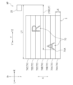
記憶部52は、画像データを記憶する。画像データは、所定の画像70(図4参照)を表す。画像データは、総パス数を含む。総パス数は、インクが吐出される印刷パス72(図4参照)の数である印刷パス数とインクが吐出されない非印刷パス74(図4参照)の数である非印刷パス数とから構成される。本実施形態の総パス数は、1つの画像データに基づいて画像を印刷するときに記録媒体5が副走査方向Xに所定の距離ずつ搬送される回数と等しい。図4に示す例では、総パス数は7であり、前方から後方に向けて非印刷パス74A、印刷パス72A、印刷パス72B、非印刷パス74B、印刷パス72C、印刷パス72D、非印刷パス74Cの順に並ぶ。即ち、印刷パス数は4であり、非印刷パス数は3である。記憶部52は、記録媒体5を副走査方向Xに所定の距離LXだけ搬送するのに要する搬送時間を記憶する。ここでは、記録媒体5は、後方から前方(即ち副走査方向Xの上流側から下流側)に向けて搬送される。所定の距離LXは各パスにおいて共通である。即ち、記録媒体5所定の距離LXずつ前方(即ち副走査方向Xの下流側)に搬送される。
The
設定部54は、1印刷パス当たりの印刷幅LYを設定する。印刷幅LYは、例えば、操作パネル15を介してユーザによって設定される。1印刷パスにおいて、キャリッジ25は主走査方向Yの右方から左方に向かう方向である往路方向Y1に印刷幅LYだけ移動し、その後、主走査方向Yの左方から右方に向かう方向である復路方向Y2に印刷幅LYだけ移動する。図4に示す例では、印刷幅LYは、移動開始位置HPに位置するキャリッジ25の右端から記録媒体5の左端までの長さである。なお、印刷幅LYは、画像70のうちキャリッジ25の移動開始位置HPから主走査方向Yに最も離れた部分にインクを吐出することが可能な最小の長さに設定されてもよい。図4に示す例では、印刷幅LYMは、画像70のうちキャリッジ25の移動開始位置HPから主走査方向Yに最も離れた部分70Aにインクを吐出することが可能な最小の長さである。
The setting
画像印刷部56は、キャリッジモータ24、フィードモータ33およびインクヘッド40を制御することで記録媒体5に画像の印刷を行う。画像印刷部56は、記憶部52に記憶された画像データに基づいた画像を、往路方向印刷および復路方向印刷によって記録媒体5上に印刷する。ここで、「往路方向印刷」とは、往路方向Y1にインクヘッド40を移動させながら記録媒体5にノズル41からインクを吐出させる印刷を意味する。また、「復路方向印刷」とは、復路方向Y2にインクヘッド40を移動させながら記録媒体5にノズル41からインクを吐出させる印刷を意味する。画像印刷部56は、印刷パス72では往路方向印刷および復路方向印刷が各1回終了すると、フィードモータ33を制御して、記録媒体5を前方(即ち副走査方向Xの下流側)に搬送する。また、画像印刷部56は、非印刷パス74では往路方向印刷および復路方向印刷を行うことなく(即ちキャリッジ25を主走査方向Yに移動させることなく)、フィードモータ33を制御して、記録媒体5を前方に搬送する。画像印刷部56は、往路方向印刷および復路方向印刷および記録媒体5の搬送を繰り返して、記録媒体5上に画像を印刷する。図4に示す例では、画像印刷部56は、非印刷パス74A、74B、74Cでは、キャリッジ25を主走査方向Yに移動させることなく、記録媒体5を所定の距離LXだけ前方に搬送する。また、画像印刷部56は、印刷パス72A、72B、72C、72Dでは、キャリッジ25を往路方向Y1に印刷幅LYだけ移動させた後、復路方向Y2に印刷幅LYだけ移動させて、その後記録媒体5を所定の距離LXだけ前方に搬送する。
The
計測部58は、キャリッジ25を印刷幅LYだけ主走査方向Yに1回往復移動させて、1回の往復移動に要した実移動時間を計測する。計測部58は、通常、画像印刷部56が記憶部52に記憶された画像データに基づいた画像を印刷するときに同時に実移動時間を計測する。図4に示す例では、計測部58は、印刷パス72Aにおいてキャリッジ25が印刷幅LYだけ主走査方向Yに1回往復移動したときに要した実移動時間を計測する。なお、計測部58は、画像印刷部56によって画像の印刷が開始される前に、予めキャリッジ25を設定部54によって設定された印刷幅LYだけ主走査方向Yに1回往復移動させて、1回の往復移動に要した実移動時間を計測してもよい。
The
推定部60は、記憶部52に記憶された画像データに含まれる印刷パス数および非印刷パス数、記憶部52に記憶された搬送時間、および計測部58によって計測された実移動時間に基づいて、画像を印刷するのに要する印刷時間を推定する。推定部60は、例えば、1つの印刷パスに関して、実移動時間と搬送時間との和を印刷パス時間とし、かつ、1つの非印刷パスに関して、搬送時間を非印刷パス時間とする。そして、推定部60は、印刷パス数と印刷パス時間、および非印刷パス数と非印刷パス時間から印刷時間を推定する。図4に示す例において、例えば、搬送時間をTAとしかつ実移動時間をTBとしたとき、推定部60によって印刷時間は4(TA+TB)+3TAと推定される。
The
以上のように、本実施形態のプリンタ10によると、計測部58は、設定部54によって設定された印刷幅LYだけキャリッジ25を主走査方向Yに1回往復移動させて、1回の往復移動に要した実移動時間を計測する。このように、キャリッジ25が1回の往復移動に要した実際の移動時間(即ち実移動時間)を用いるため、インクが吐出される1印刷パス72当たりの印刷時間がより正確になる。さらに、推定部60は、印刷パス数および搬送時間および実移動時間に加えて非印刷パス数に基づいて印刷時間を推定している。ここで、非印刷パス74では、キャリッジ25を主走査方向Yに移動させないため、非印刷パス74では実移動時間を考慮する必要がない。このように、推定部60は実際の印刷動作に基づいて印刷時間を推定することができるため、推定された印刷時間はより精度の高いものになる。
As described above, according to the
本実施形態のプリンタ10では、推定部60は、1つの印刷パス72に関して、実移動時間と搬送時間との和を印刷パス時間とし、かつ、1つの非印刷パス74に関して、搬送時間を非印刷パス時間とする。これにより、印刷時間をより精度高く推定することができる。
In the
本実施形態のプリンタ10では、印刷幅LYMは、画像のうちキャリッジ25の移動開始位置HPから主走査方向Yに最も離れた部分70Aにインクを吐出することが可能な最小の長さに設定される。これにより、キャリッジ25の移動量を最小限に抑えることができるため、印刷時間の短縮が実現される。
In the
<第2実施形態>
次に、第2実施形態に係るプリンタ110について説明する。図5は、第2実施形態に係るプリンタ110の構成を示すブロック図である。プリンタ110は、制御装置50に代えて制御装置150を備えている点を除き、プリンタ10と同様の構成である。
Second Embodiment
Next, a
図5に示すように、制御装置150は、記憶部152と、推定部154と、画像印刷部56と、計測部158と、補正部160とを備えている。制御装置150の各部の機能は、プログラムによって実現されている。このプログラムは、例えばCDやDVDなどの記録媒体から読み込まれる。なお、このプログラムは、インターネットを通じてダウンロードされるものであってもよい。また、制御装置150の各部の機能は、プロセッサおよび/または回路などによって実現可能なものであってもよい。なお、これら各部の具体的な機能については後述する。
As shown in FIG. 5, the
記憶部152は、画像データを記憶する。画像データは、所定の画像170(図6参照)を表す。画像データは、総パス数を含む。総パス数は、インクが吐出される印刷パス172(図6参照)の数である印刷パス数とインクが吐出されない非印刷パス174(図6参照)の数である非印刷パス数とから構成される。図6に示す例では、総パス数は7であり、前方から後方に向けて非印刷パス174A、印刷パス172A、印刷パス172B、非印刷パス174B、印刷パス172C、印刷パス172D、非印刷パス174Cの順に並ぶ。即ち、印刷パス数は4であり、非印刷パス数は3である。印刷パス172には、1印刷パス当たりの印刷幅LYが関連付けられている。ここでの印刷幅LYは、印刷パス172に含まれる画像170を印刷するのに最低限必要な印刷幅である。図6に示す例では、印刷パス172Aには印刷幅LY1が関連付けられ、印刷パス172Bには印刷幅LY2が関連付けられ、印刷パス172C、172Dには印刷幅LY3が関連付けられている。印刷幅LY1は、印刷パス172Aに含まれる画像170のうちキャリッジ25の移動開始位置HPから主走査方向Yに最も離れた部分170Aにインクを吐出することが可能な最小の長さである。印刷幅LY2は、印刷パス172Bに含まれる画像170のうちキャリッジ25の移動開始位置HPから主走査方向Yに最も離れた部分170Bにインクを吐出することが可能な最小の長さである。印刷幅LY3は、印刷パス172Cおよび印刷パス172Dに含まれる画像170のうちキャリッジ25の移動開始位置HPから主走査方向Yに最も離れた部分170Cにインクを吐出することが可能な最小の長さである。記憶部152は、記録媒体5を副走査方向Xに所定の距離LXだけ搬送するのに要する搬送時間を記憶する。所定の距離LXは各パスにおいて共通である。記憶部152は、キャリッジ25を印刷幅だけ主走査方向Yに1回往復移動させるときの1回の往復移動に要する移動時間と1印刷パス当たりの印刷幅との関係を示したテーブルを記憶する。
The
推定部154は、記憶部152に記憶された画像データに含まれる印刷パス数および非印刷パス数および印刷幅、テーブルおよび搬送時間に基づいて、画像を印刷するのに要する印刷時間を推定する。推定部154は、例えば、印刷パス毎に移動時間と搬送時間との和を印刷パス時間とし、かつ、1つの非印刷パスに関して、搬送時間を非印刷パス時間とする。そして、推定部154は、印刷パス数と印刷パス時間、および非印刷パス数と非印刷パス時間から印刷時間を推定する。推定部154は、画像印刷部56による印刷が開始される前に、印刷時間を推定する。推定部154は、例えば、外部機器から送信された画像データを受信したときに、印刷時間を推定する。図6に示す例において、例えば、搬送時間をTA、印刷パス172Aの移動時間をTC、印刷パス172Bの移動時間をTD、印刷パス172C、172Cの移動時間をTEとしたとき、推定部154によって印刷時間は(TA+TC)+(TA+TD)+2(TA+TE)+3TAと推定される。
The
図6に示す例では、画像印刷部56は、非印刷パス174A、174B、174Cでは、キャリッジ25を主走査方向Yに移動させることなく、記録媒体5を所定の距離LXだけ前方(即ち副走査方向Xの下流側)に搬送する。また、画像印刷部56は、印刷パス172A、172B、172C、172Dでは、それぞれ、キャリッジ25を往路方向Y1に印刷幅LY1、LY2、LY3、LY3だけ移動させた後、復路方向Y2に印刷幅LY1、LY2、LY3、LY3だけ移動させて、その後記録媒体5を所定の距離LXだけ前方に搬送する。このように、第2実施形態では、画像170を印刷するときの印刷幅LYは印刷パス毎に異なり得る。
6, in the non-printing passes 174A, 174B, and 174C, the
計測部158は、記憶部152に記憶された画像データに基づいてキャリッジ25を印刷幅LYだけ主走査方向Yに1回往復移動させたときの1回の往復移動に要した実移動時間を計測する。計測部158は、通常、画像印刷部56が記憶部152に記憶された画像データに基づいた画像を印刷するときに、同時に印刷パス172毎に実移動時間を計測する。図6に示す例では、計測部158は、印刷パス172A、172B、172C、172Dにおいてキャリッジ25がそれぞれ印刷幅LY1、LY2、LY3、LY3だけ主走査方向Yに1回往復移動したときに要した実移動時間を計測する。
The
補正部160は、計測部158によって測定された実移動時間に基づいて推定部154によって推定された印刷時間を補正する。なお、補正部160は、計測部158によって測定された実移動時間とテーブルに示された移動時間とに差がない場合には、印刷時間を補正しない。また、補正部160は、計測部158によって測定された実移動時間に基づいて記憶部152に記憶されたテーブルの移動時間を補正する。例えば、テーブルの印刷幅LY1に関連付けられた移動時間がS1秒であって、計測部158によって測定された実移動時間がS2秒の場合、補正部160は、テーブルの印刷幅LY1に関連付けられた移動時間をS2秒に補正する。
The
以上のように、本実施形態のプリンタ110によると、推定部154は、移動時間と印刷幅LYとの関係を示したテーブルに基づいて印刷時間を推定している。このように、予め測定された移動時間を用いるため、インクが吐出される1印刷パス172当たりの印刷時間がより正確になる。さらに、推定部154は、印刷パス数および搬送時間およびテーブルに加えて非印刷パス数に基づいて印刷時間を推定している。ここで、非印刷パス174では、キャリッジ25を主走査方向Yに移動させないため、非印刷パス174では移動時間を考慮する必要がない。このように、推定部154は予め測定された印刷動作に基づいて印刷時間を推定することができるため、推定された印刷時間はより精度の高いものになる。
As described above, according to the
本実施形態のプリンタ110では、推定部154は、印刷パス172毎に移動時間と搬送時間との和を印刷パス時間とし、かつ、1つの非印刷パス174に関して、搬送時間を非印刷パス時間とする。これにより、印刷時間をより精度高く推定することができる。
In the
本実施形態のプリンタ110では、制御装置150は、画像データに基づいてキャリッジ25を印刷幅LYだけ主走査方向Yに1回往復移動させたときの1回の往復移動に要した実移動時間を計測する計測部158と、実移動時間に基づいて印刷時間を補正する補正部160と、を備えている。ここで、キャリッジ25は経時変化によって移動時間が変化する虞がある。そこで、キャリッジ25が1回の往復移動に要した実際の移動時間(即ち実移動時間)に基づいて印刷時間を補正することで、印刷時間がより正確になる。
In the
本実施形態のプリンタ110では、補正部160は、実移動時間に基づいてテーブルの移動時間を補正する。これにより、インクが吐出される1印刷パス172当たりの印刷時間がより正確になる。
In the
以上、本発明の好適な実施形態について説明した。しかし、上述の各実施形態は例示に過ぎず、本発明は他の種々の形態で実施することができる。 The above describes preferred embodiments of the present invention. However, the above-described embodiments are merely examples, and the present invention can be implemented in various other forms.
ここで開示される技術は様々なタイプのプリンタに適用することができる。上述した実施形態で示したロール状の記録媒体5を搬送する、所謂、Roll-to-Rollタイプのプリンタ10の他、例えばフラットベッドタイプのプリンタにも同様に適用することができる。
The technology disclosed herein can be applied to various types of printers. In addition to the so-called roll-to-
5 記録媒体
10 プリンタ(インクジェットプリンタ)
25 キャリッジ
30 搬送装置
40 インクヘッド
50 制御装置
52 記憶部
54 設定部
58 計測部
60 推定部
70 画像
72 印刷パス
74 非印刷パス
5 Recording
25
Claims (3)
前記インクヘッドが搭載され、主走査方向に移動可能なキャリッジと、
前記記録媒体を前記主走査方向と直交する副走査方向に搬送する搬送装置と、
前記インクヘッド、前記キャリッジおよび前記搬送装置を制御する制御装置と、を備え、
前記制御装置は、
前記画像のデータであって、インクが吐出される印刷パスの数である印刷パス数とインクが吐出されない非印刷パスの数である非印刷パス数とから構成される総パス数を含む画像データと、前記記録媒体を前記副走査方向に所定の距離だけ搬送するのに要する搬送時間と、を記憶する記憶部と、
1印刷パス当たりの印刷幅を設定する設定部と、
前記画像の印刷が開始される前に、前記キャリッジを前記印刷幅だけ前記主走査方向に1回往復移動させて、1回の往復移動に要した実移動時間を計測する計測部と、
前記画像データと前記搬送時間と前記実移動時間とに基づいて、前記画像を印刷するのに要する印刷時間を推定する推定部と、を備えている、インクジェットプリンタ。 an ink head that ejects ink onto a recording medium to print an image;
a carriage on which the ink head is mounted and which is movable in a main scanning direction;
a conveying device that conveys the recording medium in a sub-scanning direction perpendicular to the main scanning direction;
a control device that controls the ink head, the carriage, and the transport device,
The control device includes:
a storage unit that stores image data of the image, the image data including a total number of passes configured from a number of printing passes, which is the number of printing passes in which ink is ejected, and a number of non-printing passes, which is the number of non-printing passes in which ink is not ejected, and a transport time required to transport the recording medium a predetermined distance in the sub-scanning direction;
A setting unit that sets a printing width per printing pass;
a measurement unit that moves the carriage back and forth once in the main scanning direction by the printing width before printing of the image is started , and measures an actual movement time required for one back and forth movement;
an estimation unit that estimates a printing time required to print the image based on the image data, the transport time, and the actual movement time.
Priority Applications (1)
| Application Number | Priority Date | Filing Date | Title |
|---|---|---|---|
| JP2020143337A JP7628005B2 (en) | 2020-08-27 | 2020-08-27 | Inkjet printer |
Applications Claiming Priority (1)
| Application Number | Priority Date | Filing Date | Title |
|---|---|---|---|
| JP2020143337A JP7628005B2 (en) | 2020-08-27 | 2020-08-27 | Inkjet printer |
Publications (2)
| Publication Number | Publication Date |
|---|---|
| JP2022038711A JP2022038711A (en) | 2022-03-10 |
| JP7628005B2 true JP7628005B2 (en) | 2025-02-07 |
Family
ID=80498054
Family Applications (1)
| Application Number | Title | Priority Date | Filing Date |
|---|---|---|---|
| JP2020143337A Active JP7628005B2 (en) | 2020-08-27 | 2020-08-27 | Inkjet printer |
Country Status (1)
| Country | Link |
|---|---|
| JP (1) | JP7628005B2 (en) |
Citations (8)
| Publication number | Priority date | Publication date | Assignee | Title |
|---|---|---|---|---|
| JP2000203131A (en) | 1999-01-18 | 2000-07-25 | Ricoh Co Ltd | Ink jet recording device |
| JP2005035024A (en) | 2003-07-16 | 2005-02-10 | Ricoh Co Ltd | Inkjet recording apparatus, recording time calculation method, and computer-readable recording medium storing a program for executing the method |
| JP2005287253A (en) | 2004-03-30 | 2005-10-13 | Seiko Epson Corp | Electronics |
| JP2007090615A (en) | 2005-09-28 | 2007-04-12 | Sony Corp | Thermal head printer, print kiosk device, total printing time prediction device, total printing time prediction method, total printing time display method and program |
| JP2007237673A (en) | 2006-03-10 | 2007-09-20 | Canon Inc | Inkjet recording device |
| JP2008132668A (en) | 2006-11-28 | 2008-06-12 | Canon Inc | Recording device and printing time detection method |
| JP2011079180A (en) | 2009-10-05 | 2011-04-21 | Canon Inc | Printing device, processing method of the same, and information processor |
| JP2013208879A (en) | 2012-03-30 | 2013-10-10 | Ricoh Co Ltd | Image forming apparatus |
-
2020
- 2020-08-27 JP JP2020143337A patent/JP7628005B2/en active Active
Patent Citations (8)
| Publication number | Priority date | Publication date | Assignee | Title |
|---|---|---|---|---|
| JP2000203131A (en) | 1999-01-18 | 2000-07-25 | Ricoh Co Ltd | Ink jet recording device |
| JP2005035024A (en) | 2003-07-16 | 2005-02-10 | Ricoh Co Ltd | Inkjet recording apparatus, recording time calculation method, and computer-readable recording medium storing a program for executing the method |
| JP2005287253A (en) | 2004-03-30 | 2005-10-13 | Seiko Epson Corp | Electronics |
| JP2007090615A (en) | 2005-09-28 | 2007-04-12 | Sony Corp | Thermal head printer, print kiosk device, total printing time prediction device, total printing time prediction method, total printing time display method and program |
| JP2007237673A (en) | 2006-03-10 | 2007-09-20 | Canon Inc | Inkjet recording device |
| JP2008132668A (en) | 2006-11-28 | 2008-06-12 | Canon Inc | Recording device and printing time detection method |
| JP2011079180A (en) | 2009-10-05 | 2011-04-21 | Canon Inc | Printing device, processing method of the same, and information processor |
| JP2013208879A (en) | 2012-03-30 | 2013-10-10 | Ricoh Co Ltd | Image forming apparatus |
Also Published As
| Publication number | Publication date |
|---|---|
| JP2022038711A (en) | 2022-03-10 |
Similar Documents
| Publication | Publication Date | Title |
|---|---|---|
| US7914112B2 (en) | Printing apparatus with switchover section that switches over patterns of velocity data | |
| JP5928093B2 (en) | Inkjet recording device | |
| JP6540387B2 (en) | Printing apparatus control method and printing apparatus | |
| US7431521B2 (en) | Printing method, printing apparatus, and computer-readable storage medium for shortening stoppage period of both motors | |
| JP7628005B2 (en) | Inkjet printer | |
| US10940703B2 (en) | Liquid jetting apparatus | |
| US10688781B2 (en) | Printing apparatus | |
| JP4192629B2 (en) | Printing apparatus, printing method, and printing system | |
| JP6003156B2 (en) | Image forming apparatus | |
| JP5741135B2 (en) | Inkjet recording device | |
| JP2006334810A (en) | Inkjet recording device | |
| JP5404120B2 (en) | Discharge timing correction apparatus and discharge timing correction method | |
| JP2009113329A (en) | Inkjet recording device | |
| JP2021194897A (en) | Recording device and control method in recording device | |
| JP6031794B2 (en) | Inkjet recording device | |
| CN102139582B (en) | Image forming device | |
| JP2011143556A (en) | Image forming apparatus and method for controlling the same | |
| JP2004338303A (en) | Printing apparatus, printing method and printing system | |
| JP5037430B2 (en) | Conveying apparatus in image recording apparatus, and conveying speed correction method in conveying apparatus of image recording apparatus | |
| JP2006007640A (en) | Printing apparatus, printing method, and printing system | |
| JP6111621B2 (en) | Ink discharge timing correction method for ink jet printer and ink jet printer | |
| JP4027002B2 (en) | Inkjet recording apparatus and image forming apparatus | |
| JP4466263B2 (en) | Printing apparatus, printing method, and printing system | |
| JP2005088217A (en) | Printing device | |
| JP4360185B2 (en) | Serial printer |
Legal Events
| Date | Code | Title | Description |
|---|---|---|---|
| A621 | Written request for application examination |
Free format text: JAPANESE INTERMEDIATE CODE: A621 Effective date: 20230515 |
|
| A977 | Report on retrieval |
Free format text: JAPANESE INTERMEDIATE CODE: A971007 Effective date: 20240229 |
|
| A131 | Notification of reasons for refusal |
Free format text: JAPANESE INTERMEDIATE CODE: A131 Effective date: 20240402 |
|
| A521 | Request for written amendment filed |
Free format text: JAPANESE INTERMEDIATE CODE: A523 Effective date: 20240530 |
|
| A131 | Notification of reasons for refusal |
Free format text: JAPANESE INTERMEDIATE CODE: A131 Effective date: 20240820 |
|
| A711 | Notification of change in applicant |
Free format text: JAPANESE INTERMEDIATE CODE: A712 Effective date: 20250114 |
|
| TRDD | Decision of grant or rejection written | ||
| A01 | Written decision to grant a patent or to grant a registration (utility model) |
Free format text: JAPANESE INTERMEDIATE CODE: A01 Effective date: 20250121 |
|
| A61 | First payment of annual fees (during grant procedure) |
Free format text: JAPANESE INTERMEDIATE CODE: A61 Effective date: 20250128 |
|
| R150 | Certificate of patent or registration of utility model |
Ref document number: 7628005 Country of ref document: JP Free format text: JAPANESE INTERMEDIATE CODE: R150 |