JP7626041B2 - Wire Harness - Google Patents
Wire Harness Download PDFInfo
- Publication number
- JP7626041B2 JP7626041B2 JP2021192254A JP2021192254A JP7626041B2 JP 7626041 B2 JP7626041 B2 JP 7626041B2 JP 2021192254 A JP2021192254 A JP 2021192254A JP 2021192254 A JP2021192254 A JP 2021192254A JP 7626041 B2 JP7626041 B2 JP 7626041B2
- Authority
- JP
- Japan
- Prior art keywords
- path
- fixing
- regulating member
- path regulating
- wire harness
- Prior art date
- Legal status (The legal status is an assumption and is not a legal conclusion. Google has not performed a legal analysis and makes no representation as to the accuracy of the status listed.)
- Active
Links
Images


Classifications
-
- H—ELECTRICITY
- H01—ELECTRIC ELEMENTS
- H01B—CABLES; CONDUCTORS; INSULATORS; SELECTION OF MATERIALS FOR THEIR CONDUCTIVE, INSULATING OR DIELECTRIC PROPERTIES
- H01B7/00—Insulated conductors or cables characterised by their form
- H01B7/17—Protection against damage caused by external factors, e.g. sheaths or armouring
-
- B—PERFORMING OPERATIONS; TRANSPORTING
- B60—VEHICLES IN GENERAL
- B60R—VEHICLES, VEHICLE FITTINGS, OR VEHICLE PARTS, NOT OTHERWISE PROVIDED FOR
- B60R16/00—Electric or fluid circuits specially adapted for vehicles and not otherwise provided for; Arrangement of elements of electric or fluid circuits specially adapted for vehicles and not otherwise provided for
- B60R16/02—Electric or fluid circuits specially adapted for vehicles and not otherwise provided for; Arrangement of elements of electric or fluid circuits specially adapted for vehicles and not otherwise provided for electric constitutive elements
- B60R16/0207—Wire harnesses
- B60R16/0215—Protecting, fastening and routing means therefor
-
- H—ELECTRICITY
- H01—ELECTRIC ELEMENTS
- H01B—CABLES; CONDUCTORS; INSULATORS; SELECTION OF MATERIALS FOR THEIR CONDUCTIVE, INSULATING OR DIELECTRIC PROPERTIES
- H01B7/00—Insulated conductors or cables characterised by their form
- H01B7/40—Insulated conductors or cables characterised by their form with arrangements for facilitating mounting or securing
-
- H—ELECTRICITY
- H02—GENERATION; CONVERSION OR DISTRIBUTION OF ELECTRIC POWER
- H02G—INSTALLATION OF ELECTRIC CABLES OR LINES, OR OF COMBINED OPTICAL AND ELECTRIC CABLES OR LINES
- H02G3/00—Installations of electric cables or lines or protective tubing therefor in or on buildings, equivalent structures or vehicles
- H02G3/02—Details
- H02G3/06—Joints for connecting lengths of protective tubing or channels, to each other or to casings, e.g. to distribution boxes; Ensuring electrical continuity in the joint
-
- H—ELECTRICITY
- H02—GENERATION; CONVERSION OR DISTRIBUTION OF ELECTRIC POWER
- H02G—INSTALLATION OF ELECTRIC CABLES OR LINES, OR OF COMBINED OPTICAL AND ELECTRIC CABLES OR LINES
- H02G3/00—Installations of electric cables or lines or protective tubing therefor in or on buildings, equivalent structures or vehicles
- H02G3/30—Installations of cables or lines on walls, floors or ceilings
- H02G3/32—Installations of cables or lines on walls, floors or ceilings using mounting clamps
-
- H—ELECTRICITY
- H01—ELECTRIC ELEMENTS
- H01B—CABLES; CONDUCTORS; INSULATORS; SELECTION OF MATERIALS FOR THEIR CONDUCTIVE, INSULATING OR DIELECTRIC PROPERTIES
- H01B7/00—Insulated conductors or cables characterised by their form
- H01B7/0045—Cable-harnesses
-
- H—ELECTRICITY
- H02—GENERATION; CONVERSION OR DISTRIBUTION OF ELECTRIC POWER
- H02G—INSTALLATION OF ELECTRIC CABLES OR LINES, OR OF COMBINED OPTICAL AND ELECTRIC CABLES OR LINES
- H02G3/00—Installations of electric cables or lines or protective tubing therefor in or on buildings, equivalent structures or vehicles
- H02G3/02—Details
- H02G3/04—Protective tubing or conduits, e.g. cable ladders or cable troughs
Landscapes
- Engineering & Computer Science (AREA)
- Architecture (AREA)
- Civil Engineering (AREA)
- Structural Engineering (AREA)
- Mechanical Engineering (AREA)
- Details Of Indoor Wiring (AREA)
- Joints That Cut Off Fluids, And Hose Joints (AREA)
- Protection Of Pipes Against Damage, Friction, And Corrosion (AREA)
- Insulated Conductors (AREA)
Description
本開示は、ワイヤハーネスに関する。 This disclosure relates to a wire harness.
従来、車両用のワイヤハーネスとしては、電線部材及び電線部材を覆う外装部材を有するワイヤハーネス本体と、外装部材に外周に取り付けられ、ワイヤハーネス本体の経路を規制する経路規制部材とを備えたものがある(例えば、特許文献1参照)。 Conventionally, there is a wire harness for a vehicle that includes a wire harness main body having an electric wire member and an exterior member that covers the electric wire member, and a path control member that is attached to the outer periphery of the exterior member and controls the path of the wire harness main body (see, for example, Patent Document 1).
ところで、上記のようなワイヤハーネスにおいて、経路規制部材は、他の経路規制部材等の取付部材に対して取り付けられることがあり、その場合、経路規制部材と取付部材との取付部位にがたつきが生じないことが望まれる。なお、取付部位のがたつきは、例えば、振動等によって取付部位を破損させる原因となる。 In the above-mentioned wire harness, the path-regulating member may be attached to a mounting member of another path-regulating member, etc. In such a case, it is desirable that there is no rattle at the mounting portion between the path-regulating member and the mounting member. Furthermore, rattle at the mounting portion may cause the mounting portion to be damaged by, for example, vibration, etc.
本開示の目的は、がたつきを抑制可能としたワイヤハーネスを提供することにある。 The objective of this disclosure is to provide a wire harness that can suppress rattling.
本開示のワイヤハーネスは、電線部材及び前記電線部材の外周を覆う外装部材を有するワイヤハーネス本体と、前記外装部材の外周に取り付けられ、前記ワイヤハーネス本体の経路を規制する第1経路規制部材と、前記第1経路規制部材の長さ方向の一部における外周に取り付けられる取付部材と、を備え、前記第1経路規制部材は、前記第1経路規制部材の長さ方向と直交する方向に開口するとともに前記第1経路規制部材の長さ方向の全体にわたって延びる挿入口を有し、前記取付部材は、前記第1経路規制部材の周方向の一部を覆う受け部と、前記受け部と共に前記第1経路規制部材の全周を覆う蓋と、前記受け部における周方向の両端部に設けられた第1固定部と、前記蓋における周方向の両端部に設けられた第2固定部と、重ね合わされた前記第1固定部及び前記第2固定部に対して取り付けられて前記第1固定部と前記第2固定部とが離れることを阻止する固定部材と、を有し、前記受け部と前記蓋とは、前記第1経路規制部材を挟み込んでいる。 The wire harness of the present disclosure includes a wire harness main body having an electric wire member and an exterior member covering the outer periphery of the electric wire member, a first path regulating member attached to the outer periphery of the exterior member and regulating the path of the wire harness main body, and an attachment member attached to the outer periphery of the first path regulating member in a portion of the longitudinal direction, the first path regulating member having an insertion opening that opens in a direction perpendicular to the longitudinal direction of the first path regulating member and extends over the entire longitudinal direction of the first path regulating member, the attachment member includes a receiving portion that covers a portion of the circumferential direction of the first path regulating member, a lid that covers the entire periphery of the first path regulating member together with the receiving portion, a first fixing portion provided at both circumferential ends of the receiving portion, a second fixing portion provided at both circumferential ends of the lid, and a fixing member that is attached to the overlapped first fixing portion and second fixing portion to prevent the first fixing portion and the second fixing portion from separating, and the receiving portion and the lid sandwich the first path regulating member.
本開示のワイヤハーネスによれば、がたつきを抑制できる。 The wire harness disclosed herein can reduce rattling.
[本開示の実施形態の説明]
最初に本開示の実施態様を列記して説明する。
本開示のワイヤハーネスは、
[1]電線部材及び前記電線部材の外周を覆う外装部材を有するワイヤハーネス本体と、前記外装部材の外周に取り付けられ、前記ワイヤハーネス本体の経路を規制する第1経路規制部材と、前記第1経路規制部材の長さ方向の一部における外周に取り付けられる取付部材と、を備え、前記第1経路規制部材は、前記第1経路規制部材の長さ方向と直交する方向に開口するとともに前記第1経路規制部材の長さ方向の全体にわたって延びる挿入口を有し、前記取付部材は、前記第1経路規制部材の周方向の一部を覆う受け部と、前記受け部と共に前記第1経路規制部材の全周を覆う蓋と、前記受け部における周方向の両端部に設けられた第1固定部と、前記蓋における周方向の両端部に設けられた第2固定部と、重ね合わされた前記第1固定部及び前記第2固定部に対して取り付けられて前記第1固定部と前記第2固定部とが離れることを阻止する固定部材と、を有し、前記受け部と前記蓋とは、前記第1経路規制部材を挟み込んでいる。
[Description of the embodiments of the present disclosure]
First, the embodiments of the present disclosure will be listed and described.
The wire harness of the present disclosure includes:
[1] A wire harness main body having an electric wire member and an exterior member covering an outer periphery of the electric wire member, a first path regulating member attached to the outer periphery of the exterior member and regulating a path of the wire harness main body, and an attachment member attached to the outer periphery of the first path regulating member in a part of a longitudinal direction, wherein the first path regulating member has an insertion opening that opens in a direction perpendicular to the longitudinal direction of the first path regulating member and extends over the entire longitudinal direction of the first path regulating member, and the attachment member has a receiving portion covering a part of a circumferential direction of the first path regulating member, a lid covering the entire circumference of the first path regulating member together with the receiving portion, a first fixing portion provided at both circumferential ends of the receiving portion, a second fixing portion provided at both circumferential ends of the lid, and a fixing member attached to the overlapping first fixing portion and the second fixing portion and preventing the first fixing portion and the second fixing portion from being separated, and the receiving portion and the lid sandwich the first path regulating member.
同構成によれば、受け部における周方向の両端部には第1固定部が設けられ、蓋における周方向の両端部には第2固定部が設けられる。そして、重ね合わされた第1固定部及び第2固定部に対して固定部材が取り付けられ、固定部材によって第1固定部と第2固定部とが離れることは阻止される。このようにすると、例えば、受け部に蓋が薄肉のヒンジ部を介して一体成形され、閉状態で爪部の係合によって受け部に蓋がロックされる構成に比べて、受け部と蓋とのがたつきが抑制される。すなわち、薄肉のヒンジ部及び爪部を有する構成では、ヒンジ部及び爪部の各部位で受け部と蓋とのがたつきが生じ易いが、それを回避することができる。よって、受け部と蓋とで第1経路規制部材をがたつきなく挟み込むことができ、第1経路規制部材と取付部材とのがたつきを抑制できる。 According to this configuration, a first fixing portion is provided at both circumferential ends of the receiving portion, and a second fixing portion is provided at both circumferential ends of the lid. A fixing member is attached to the overlapping first and second fixing portions, and the fixing member prevents the first and second fixing portions from separating. In this way, rattling between the receiving portion and the lid is suppressed compared to a configuration in which, for example, the lid is integrally molded with the receiving portion via a thin hinge portion, and the lid is locked to the receiving portion by engagement of the claw portion in the closed state. In other words, in a configuration having a thin hinge portion and claw portion, rattling between the receiving portion and the lid is likely to occur at each part of the hinge portion and the claw portion, but this can be avoided. Therefore, the first path regulating member can be sandwiched between the receiving portion and the lid without rattling, and rattling between the first path regulating member and the mounting member can be suppressed.
[2]前記固定部材は、重ね合わされた前記第1固定部及び前記第2固定部に対して前記取付部材の長さ方向に沿ったスライド移動によって取付可能とされ取り付けられていることが好ましい。 [2] It is preferable that the fixing member is attachable to the overlapping first fixing part and the second fixing part by sliding movement along the length of the mounting member.
同構成によれば、固定部材は、取付部材の長さ方向に沿ったスライド移動によって取り付けられるため、例えば、第1固定部と第2固定部とが離れることを強固に阻止することが可能となる。すなわち、例えば、固定部材が取付部材の径方向外側から撓められながら取り付けられる構成では、固定部材が撓み易い設計となることで、第1固定部及び第2固定部に対して外れ易くなる虞があるが、これを回避することができる。 According to this configuration, the fixing member is attached by sliding movement along the length of the mounting member, so it is possible to firmly prevent, for example, the first fixing part and the second fixing part from separating. That is, for example, in a configuration in which the fixing member is attached while being bent from the radial outside of the mounting member, the fixing member is designed to be easily bent, which may cause it to easily come off from the first fixing part and the second fixing part, but this can be avoided.
[3]前記第1固定部及び前記第2固定部の少なくとも一方は、前記固定部材の取り付けを許容しながらも取り付けられた状態から取り外す方向に係合して前記固定部材の脱落を抑制する係合凸部を有することが好ましい。 [3] At least one of the first fixing portion and the second fixing portion preferably has an engaging protrusion that allows the fixing member to be attached while engaging in a direction to remove the fixing member from the attached state, thereby preventing the fixing member from falling off.
同構成によれば、第1固定部及び第2固定部の少なくとも一方は、固定部材の取り付けを許容しながらも取り付けられた状態から取り外す方向に係合して固定部材の脱落を抑制する係合凸部を有するため、固定部材の脱落が抑制される。 According to this configuration, at least one of the first and second fixing parts has an engaging protrusion that allows the fixing member to be attached while engaging in a direction to remove the fixing member from the attached state, thereby preventing the fixing member from falling off.
[4]前記係合凸部は、前記取付部材の長さ方向において取り付けられた状態の前記固定部材の両側に設けられていることが好ましい。
同構成によれば、係合凸部は、取付部材の長さ方向において取り付けられた状態の固定部材の両側に設けられているため、例えば、固定部材を取付部材の長さ方向のどちら側からでも取り付けることが可能となる。
[4] It is preferable that the engaging protrusions are provided on both sides of the fixing member in the longitudinal direction of the mounting member when the mounting member is in the mounted state.
According to this configuration, the engaging protrusions are provided on both sides of the fixing member in the attached state in the longitudinal direction of the mounting member, so that, for example, the fixing member can be attached from either side in the longitudinal direction of the mounting member.
[5]前記固定部材は、重ね合わされた前記第1固定部及び前記第2固定部に対して前記取付部材の径方向外側から取付可能とされ取り付けられていることが好ましい。
同構成によれば、固定部材は、取付部材の径方向外側から取り付けられるため、例えば、固定部材の取り付けが容易となる。
[5] It is preferable that the fixing member is attachable to the overlapping first fixing portion and the second fixing portion from a radially outer side of the mounting member.
According to this configuration, the fixing member is attached from the radially outer side of the mounting member, which makes it easy to attach the fixing member, for example.
[6]前記取付部材は、前記外装部材の外周に取り付けられ、前記ワイヤハーネス本体の経路を規制する第2経路規制部材であり、前記受け部は、前記第2経路規制部材の長さ方向の端部に設けられ、前記第1経路規制部材の長さ方向の端部における周方向の一部を覆うことが好ましい。 [6] The mounting member is a second path-regulating member that is attached to the outer periphery of the exterior member and regulates the path of the wire harness main body, and the receiving portion is preferably provided at the end in the longitudinal direction of the second path-regulating member and covers a circumferential portion of the end in the longitudinal direction of the first path-regulating member.
同構成によれば、受け部は、第2経路規制部材の長さ方向の端部に設けられ、第1経路規制部材の長さ方向の端部における周方向の一部を覆うため、第1経路規制部材と第2経路規制部材とが長さ方向に連結される。よって、ワイヤハーネス本体は、第1経路規制部材と第2経路規制部材とによって経路が連続的に規制される。 According to this configuration, the receiving portion is provided at the end of the second path regulating member in the longitudinal direction and covers a part of the circumference of the end of the first path regulating member in the longitudinal direction, so that the first path regulating member and the second path regulating member are connected in the longitudinal direction. Therefore, the path of the wire harness main body is continuously regulated by the first path regulating member and the second path regulating member.
[7]前記第1経路規制部材は、前記ワイヤハーネス本体の経路において直線状をなす部分である直線部の経路を規制しており、前記第2経路規制部材は、前記ワイヤハーネス本体の経路において屈曲する部分である屈曲部の経路を規制していることが好ましい。 [7] It is preferable that the first path regulating member regulates the path of a straight portion, which is a straight portion in the path of the wire harness main body, and the second path regulating member regulates the path of a bent portion, which is a bent portion in the path of the wire harness main body.
同構成によれば、第1経路規制部材によって直線部の経路が規制され、第2経路規制部材によって屈曲部の経路が規制される。これにより、ワイヤハーネス本体の直線部の経路及び屈曲部の経路がそれぞれ所望の経路から外れることが連続的に抑制される。 According to this configuration, the path of the straight section is restricted by the first path restriction member, and the path of the bent section is restricted by the second path restriction member. This continuously prevents the paths of the straight section and the bent section of the wire harness main body from deviating from the desired paths.
[本開示の実施形態の詳細]
本開示のワイヤハーネスの具体例を、以下に図面を参照しつつ説明する。各図面では、説明の便宜上、構成の一部を誇張又は簡略化して示す場合がある。また、各部分の寸法比率については各図面で異なる場合がある。本明細書における「平行」や「直交」は、厳密に平行や直交の場合のみでなく、本実施形態における作用効果を奏する範囲内で概ね平行や直交の場合も含まれる。なお、本発明はこれらの例示に限定されるものではなく、特許請求の範囲によって示され、特許請求の範囲と均等の意味及び範囲内でのすべての変更が含まれることが意図される。
[Details of the embodiment of the present disclosure]
Specific examples of the wire harness of the present disclosure will be described below with reference to the drawings. In each drawing, for convenience of explanation, some of the configuration may be exaggerated or simplified. In addition, the dimensional ratio of each part may differ in each drawing. In this specification, "parallel" and "orthogonal" do not only mean strictly parallel or orthogonal, but also include roughly parallel or orthogonal within the range in which the action and effect of this embodiment is achieved. Note that the present invention is not limited to these examples, but is indicated by the claims, and is intended to include all modifications within the meaning and scope equivalent to the claims.
(ワイヤハーネス10の全体構成)
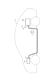
図1に示すワイヤハーネス10は、例えば、ハイブリッド車や電気自動車等の車両Vに搭載されるものである。ワイヤハーネス10は、2個以上の車載機器同士を電気的に接続する。車載機器は、車両Vに搭載された電気機器である。ワイヤハーネス10は、例えば、車両Vの前部に設置されたインバータM1と、そのインバータM1よりも車両Vの後方に設置された高圧バッテリM2とを電気的に接続する。ワイヤハーネス10は、例えば、車両Vの前後方向に延びるように長尺状に形成されている。ワイヤハーネス10は、例えば、ワイヤハーネス10の長さ方向の中間部分が車両Vの床下などの車室外を通るように車両Vに配索されている。
(Overall configuration of wire harness 10)
The
インバータM1は、例えば、車両走行の動力源となる図示しない車輪駆動用のモータと接続される。インバータM1は、高圧バッテリM2の直流電力から交流電力を生成し、その交流電力をモータに供給する。高圧バッテリM2は、例えば、数百ボルトの電圧を供給可能なバッテリである。 The inverter M1 is connected, for example, to a wheel drive motor (not shown) that serves as a power source for driving the vehicle. The inverter M1 generates AC power from the DC power of the high-voltage battery M2 and supplies the AC power to the motor. The high-voltage battery M2 is, for example, a battery capable of supplying a voltage of several hundred volts.
ワイヤハーネス10は、ワイヤハーネス本体11を有している。ワイヤハーネス本体11は、電線部材20と、電線部材20の外周を覆う筒状の外装部材30とを有している。ワイヤハーネス10は、電線部材20の両端部に取り付けられたコネクタC1,C2を有している。電線部材20の長さ方向の一端部はコネクタC1を介してインバータM1と接続されるとともに、電線部材20の長さ方向の他端部はコネクタC2を介して高圧バッテリM2と接続されている。
The
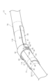
図2及び図3に示すように、ワイヤハーネス10は、外装部材30の外周に取り付けられる第1経路規制部材40と、外装部材30の外周に取り付けられる取付部材としての第2経路規制部材60とを有している。第1経路規制部材40及び第2経路規制部材60は、ワイヤハーネス本体11の配索される経路を規制している。なお、図1では、第1経路規制部材40及び第2経路規制部材60の図示を省略している。
2 and 3, the
(電線部材20の構成)
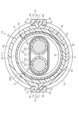
図4及び図6に示すように、電線部材20は、例えば、1本又は複数本であって、本実施形態では、2本の電線21と、複数本の電線21の外周を一括して包囲する編組部材25とを有している。
(Configuration of the wire member 20)
As shown in Figures 4 and 6, the
図6に示すように、各電線21は、導電性を有する芯線22と、芯線22の外周を囲うとともに絶縁性を有する絶縁被覆23とを有する被覆電線である。各電線21は、例えば、高電圧・大電流に対応可能な高圧電線である。各電線21は、例えば、自身に電磁シールド構造を有しないノンシールド電線であってもよいし、自身に電磁シールド構造を有するシールド電線であってもよい。本実施形態の各電線21は、ノンシールド電線である。
As shown in FIG. 6, each
芯線22としては、例えば、複数の金属素線を撚り合わせてなる撚線や単一の導体からなる単芯線などを用いることができる。単芯線としては、例えば、内部が中実構造をなす柱状の1本の金属棒からなる柱状導体や内部が中空構造をなす筒状導体などを用いることができる。芯線22としては、撚線、柱状導体や筒状導体を組み合わせて用いてもよい。芯線22の材料としては、例えば、銅系やアルミニウム系などの金属材料を用いることができる。
As the
絶縁被覆23は、例えば、芯線22の外周面を周方向全周にわたって被覆している。絶縁被覆23は、例えば、絶縁性を有する樹脂材料により構成されている。
各電線21の長さ方向と直交する平面によって電線21を切断した断面形状、つまり各電線21の横断面形状は、任意の形状に形成することができる。各電線21の横断面形状は、例えば、円形状、半円状、多角形状、正方形状、扁平形状等に形成されている。本実施形態の各電線21の横断面形状は、円形状に形成されている。
The insulating
The cross-sectional shape of each
編組部材25は、例えば、全体として複数の電線21の外周を一括して包囲する筒状をなしている。編組部材25としては、例えば、複数の金属素線が編成された編組線や、金属素線と樹脂素線とを組み合わせて編成された編組線を用いることができる。金属素線の材料としては、例えば、銅系やアルミニウム系などの金属材料を用いることができる。図示は省略するが、編組部材25の長さ方向の両端部は、例えば、コネクタC1,C2(図1参照)などにおいてアース接続されている。
The
(外装部材30の構成)
図4に示すように、外装部材30は、電線部材20の外周を周方向全周にわたって包囲する筒状をなしている。本実施形態の外装部材30は、円筒状に形成されている。外装部材30は、例えば、外装部材30の周方向全周にわたって連続して周壁が形成されている。外装部材30は、例えば、外装部材30の内部を周方向全周にわたって密閉している。外装部材30は、例えば、飛翔物や水滴から電線部材20を保護する機能を有している。
(Configuration of exterior member 30)
As shown in Fig. 4, the
外装部材30は、例えば、可撓性を有し、容易に屈曲可能である。可撓性を有する外装部材30の例としては、例えば、樹脂製のコルゲートチューブやゴム製の防水カバーなどが挙げられる。本実施形態の外装部材30は、外装部材30の長さ方向において径が大小繰り返す蛇腹形状をなす樹脂製のコルゲートチューブである。すなわち、本実施形態の外装部材30は、外装部材30の長さ方向に沿って大径部31と大径部31よりも径の小さい小径部32とが交互に連なって設けられた蛇腹構造を有している。大径部31及び小径部32の各々は、例えば、外装部材30の周方向に沿って1周する環状をなしている。外装部材30の材料としては、例えば、ポリオレフィン、ポリアミド、ポリエステル、ABS樹脂などの合成樹脂を用いることができる。なお、図1~図3では、図面の簡略化のために、外装部材30を簡略化して図示している。
The
(第1経路規制部材40及び第2経路規制部材60の構成)
図2及び図3に示すように、第1経路規制部材40及び第2経路規制部材60の各々は、外装部材30を保持する。第1経路規制部材40及び第2経路規制部材60の各々は、例えば、外装部材30よりも堅硬である。第1経路規制部材40及び第2経路規制部材60の各々は、外装部材30に比べて、ワイヤハーネス本体11の長さ方向と直交する方向に曲がり難い硬さを有している。これにより、第1経路規制部材40及び第2経路規制部材60の各々は、ワイヤハーネス本体11の経路を規制する。例えば、第1経路規制部材40及び第2経路規制部材60の各々は、ワイヤハーネス本体11が自重などで撓んで所望の経路から外れないように、外装部材30を補助する。
(Configuration of the first
2 and 3, each of the first
図2に示すように、第1経路規制部材40は、ワイヤハーネス本体11の長さ方向において部分的に設けられている。第1経路規制部材40は、例えば、ワイヤハーネス本体11の経路のうち直線状をなす部分である直線部11Aにおいて、外装部材30の外周に取り付けられている。第1経路規制部材40は、直線部11Aにおけるワイヤハーネス本体11の経路を規制する。ここで、直線部11Aは、ワイヤハーネス本体11の経路が一方向に直線状に延びる部分である。なお、第1経路規制部材40は、ワイヤハーネス本体11の経路に応じて、単数または複数設けられる。
As shown in FIG. 2, the first
第2経路規制部材60は、ワイヤハーネス本体11の長さ方向において部分的に設けられている。第2経路規制部材60は、例えば、ワイヤハーネス本体11の経路のうち屈曲する部分である屈曲部11Bにおいて、外装部材30の外周に取り付けられている。第2経路規制部材60は、屈曲部11Bにおけるワイヤハーネス本体11の経路を規制する。ここで、屈曲部11Bは、ワイヤハーネス本体11の経路が一直線上から外れるように屈曲している部分である。なお、第2経路規制部材60は、ワイヤハーネス本体11の経路に応じて、単数または複数設けられる。
The second
(第1経路規制部材40の構成)
図6に示すように、第1経路規制部材40は、外装部材30の外周のうち外装部材30の周方向の一部を覆っている。第1経路規制部材40は、外装部材30の周方向の一部において外装部材30の外周を被覆する形状である。第1経路規制部材40の横断面形状は、全体としてC字状をなしている。第1経路規制部材40は、例えば、外装部材30の外周の半分よりも大きい範囲を覆っている。すなわち、第1経路規制部材40は、外装部材30の外周のうち外装部材30の周方向全周の半分よりも大きい範囲を覆っている。図2に示すように、第1経路規制部材40は、直線部11Aにおける外装部材30の長さ方向に沿って延びている。第1経路規制部材40は、例えば、一方向に直線状に延びる形状に形成されている。第1経路規制部材40の横断面形状は、例えば、第1経路規制部材40の長さ方向の全長にわたって一様である。
(Configuration of the first path regulating member 40)
As shown in FIG. 6, the first
第1経路規制部材40は、例えば、金属製又は樹脂製である。本実施形態の第1経路規制部材40は、樹脂製である。第1経路規制部材40の材料としては、例えば、ポリプロピレン、ポリアミド、ポリアセタールなどの合成樹脂を用いることができる。第1経路規制部材40は、例えば、押出成形や射出成形などの周知の製造方法によって製造することができる。本実施形態では、第1経路規制部材40は、押出成形によって製造された押出成形品である。よって、第1経路規制部材40の原料を長さ方向に押し出す押出成形機を用いることで、第1経路規制部材40を容易に製造することができる。また、単一の押出成形機を用いて、長さ方向の寸法が異なる複数種類の第1経路規制部材40を製造することができる。例えば、単一の押出成形機で形成された第1経路規制部材40の母材を、切断機を用いて任意の長さで切断することによって、長さ方向の寸法が異なる複数種類の第1経路規制部材40を製造することができる。
The first
第1経路規制部材40は、第1経路規制部材40の長さ方向と直交する方向に開口する挿入口40Xを有している。挿入口40Xは、第1経路規制部材40の長さ方向の全体にわたって延びている。第1経路規制部材40は、第1経路規制部材40の周方向の両端部であって挿入口40Xを形成する第1端部41及び第2端部42を有している。第1経路規制部材40は、第1端部41と第2端部42とを連結する連結部43を有している。換言すると、第1経路規制部材40は、外装部材30の周方向の一部を覆うように形成された連結部43と、連結部43の両端部に設けられた第1端部41及び第2端部42と、第1端部41及び第2端部42によって形成された挿入口40Xとを有している。
The first
図6に示すように、連結部43は、第1経路規制部材40の主部分を構成している。連結部43の径方向の厚さは、例えば、第1経路規制部材40の周方向において一様である。連結部43の横断面形状は、例えば、外装部材30の外面に沿った形状に形成されている。第1端部41と第2端部42と連結部43との横断面形状は、例えば、円弧状に形成されている。
As shown in FIG. 6, the connecting
第1端部41と第2端部42とは、第1経路規制部材40の周方向において互いに反対側に設けられている。第1端部41と第2端部42とは、第1経路規制部材40の周方向において挿入口40Xを挟んで互いに離れて設けられている。換言すると、第1経路規制部材40の周方向において第1端部41と第2端部42との間の間隙が挿入口40Xとして構成される。このように、第1経路規制部材40は、第1経路規制部材40の周方向の一部に挿入口40Xを有するC字状に形成されている。
The
第1端部41及び第2端部42の先端の横断面形状は、湾曲形状に形成されている。本実施形態の第1端部41及び第2端部42の先端の横断面形状は、円弧形状に形成されている。
The cross-sectional shape of the tip of the
第1経路規制部材40は、第1端部41の内面から突出する突出部45と、第2端部42の内面から突出する突出部46とを有している。各突出部45,46は、第1経路規制部材40の内部に挿入された外装部材30に向かって突出して外装部材30の外面に接触している。各突出部45,46は、外装部材30の大径部31の外面に接触している。突出部45は、例えば、第1端部41の先端の内面から突出している。突出部46は、例えば、第2端部42の先端の内面から突出している。各突出部45,46の横断面形状は、例えば、湾曲形状に形成されている。本実施形態の各突出部45,46の横断面形状は、円弧形状に形成されている。
The first
図3に示すように、各突出部45,46は、第1経路規制部材40の長さ方向に延びている。各突出部45,46は、例えば、第1経路規制部材40の長さ方向の全長にわたって延びている。
As shown in FIG. 3, each of the
各突出部45,46は、外装部材30を外装部材30の外側から押圧する。外装部材30は、突出部45と突出部46と連結部43とによって弾性的に挟まれている。これにより、外装部材30に対する第1経路規制部材40の連結が強固となる。
Each of the
図6に示すように、挿入口40Xの開口幅、つまり第1端部41と第2端部42との最短距離は、外装部材30の外径よりも小さい。
挿入口40Xの開口幅は、第1経路規制部材40が弾性変形することによって大きくなる。例えば、挿入口40Xの開口幅は、第1経路規制部材40の長さ方向と直交する方向から挿入口40Xに外装部材30が挿入されることにより、大きくなる。外装部材30が第1経路規制部材40の内部に挿入されると、第1経路規制部材40は元の形状に戻ろうと弾性復帰する。これにより、挿入口40Xの開口幅は外装部材30の外径よりも小さくなるため、外装部材30の外周に対して第1経路規制部材40が取り付けられる。
As shown in FIG. 6 , the opening width of the
The opening width of the
(第2経路規制部材60の構成)
図2に示すように、第2経路規制部材60は、第1経路規制部材40の長さ方向の一部における外周に取り付けられる。第2経路規制部材60は、第1経路規制部材40の長さ方向の端部における外周に取り付けられる。また、第2経路規制部材60は、屈曲部11Bにおける外装部材30の外周に取り付けられる。第2経路規制部材60は、屈曲部11Bにおける外装部材30の長さ方向に沿って延びている。第2経路規制部材60は、例えば、屈曲部11Bの形状に沿って屈曲している。
(Configuration of the second path regulating member 60)
2, the second
第2経路規制部材60は、第2経路規制本体61と、蓋62と、固定部材63とを有する。
第2経路規制部材60を構成する第2経路規制本体61と、蓋62と、固定部材63とは、例えば、それぞれ金属製又は樹脂製である。本実施形態の第2経路規制本体61と、蓋62と、固定部材63とは、樹脂製である。第2経路規制本体61と、蓋62と、固定部材63との材料としては、例えば、ポリプロピレン、ポリアミド、ポリアセタールなどの合成樹脂を用いることができる。第2経路規制本体61と、蓋62と、固定部材63とは、例えば、射出成形などの周知の製造方法によって製造することができる。
The second
The second
第2経路規制本体61は、本体部64と、受け部65とを有している。
本体部64は、外装部材30の外周のうち外装部材30の周方向の一部を覆っている。本体部64は、外装部材30の周方向の一部において外装部材30の外周を被覆する形状である。本体部64の横断面形状は、全体として半円筒形状をなしている。本体部64は、外装部材30の外周の半分を覆っている。図2に示すように、本体部64は、屈曲部11Bにおける外装部材30の長さ方向に沿って延びている。本体部64は、屈曲部11Bの形状に沿って屈曲している。
The second
The
受け部65は、第2経路規制部材60の長さ方向の端部であって本体部64の長さ方向の端部に設けられている。受け部65は、第1経路規制部材40の外周のうち第1経路規制部材40の周方向の一部を覆っている。受け部65は、第1経路規制部材40の長さ方向の端部における周方向の一部を覆っている。受け部65は、第1経路規制部材40の周方向の一部において第1経路規制部材40の外周を被覆する形状である。受け部65の横断面形状は、全体として半円筒形状をなしている。受け部65は、本体部64よりも径の大きい半円筒形状をなしている。受け部65は、第1経路規制部材40の外周の半分を覆っている。
The receiving
受け部65は、第1固定部66を有している。第1固定部66は、受け部65における周方向の両端部に設けられている。第1固定部66は、受け部65における周方向の両端部から径方向外側に突出している。図6に示すように、第1固定部66は、受け部65における周方向の端面と連続した平面であって第2経路規制部材60の径方向に沿った第1合わせ面67を有している。また、第1固定部66は、第1合わせ面67と反対側の面であって第2経路規制部材60の径方向外側に向かうほど第1合わせ面67から離れる第1傾斜面68を有している。第1傾斜面68は、係合凸部69を有している。図5に示すように、係合凸部69は、受け部65の長さ方向に2つ設けられている。係合凸部69は、受け部65においてそれぞれ受け部65の長さ方向の端部寄りに設けられている。係合凸部69は、球面状である。詳しくは、係合凸部69は、球体の半分以下の一部を一平面で切り取った形状である。
The receiving
蓋62は、受け部65と共に第1経路規制部材40の全周を覆っている。詳しくは、蓋62は、受け部65と共に第1経路規制部材40の外周に沿った周方向の全体を覆っている。本実施形態の蓋62は、第1経路規制部材40の外周の一部と、外装部材30の外周において挿入口40Xから露出した部位とを覆っている。蓋62の横断面形状は、全体として半円筒形状をなしている。蓋62は、受け部65の径と同じ径の半円筒形状をなしている。蓋62は、第1経路規制部材40の外周に沿った周方向のうち受け部65によって覆われていない部分であって、第1経路規制部材40の外周に沿った周方向の半分を覆っている。
The
蓋62は、第2固定部70を有している。第2固定部70は、蓋62における周方向の両端部に設けられている。第2固定部70は、蓋62における周方向の両端部から径方向外側に突出している。図6に示すように、第2固定部70は、蓋62における周方向の端面と連続した平面であって第2経路規制部材60の径方向に沿った第2合わせ面71を有している。また、第2固定部70は、第2合わせ面71と反対側の面であって第2経路規制部材60の径方向外側に向かうほど第2合わせ面71から離れる第2傾斜面72を有している。第2傾斜面72は、係合凸部73を有している。図5に示すように、係合凸部73は、蓋62の長さ方向に2つ設けられている。係合凸部73は、蓋62においてそれぞれ蓋62の長さ方向の端部寄りに設けられている。係合凸部73は、球面状である。詳しくは、係合凸部73は、球体の半分以下の一部を一平面で切り取った形状である。すなわち、第2固定部70は、第1固定部66と同じ形状である。
The
受け部65と蓋62とは、第1固定部66と第2固定部70とが重ね合わされた状態であって第1合わせ面67と第2合わせ面71とが重ね合わされた状態で、第1経路規制部材40の全周を覆うとともに第1経路規制部材40を挟み込むように設定されている。
The receiving
固定部材63は、重ね合わされた第1固定部66及び第2固定部70に対して取り付けられて第1固定部66と第2固定部70とが離れることを阻止する。詳しくは、固定部材63は、固定連結部74と、固定連結部74の一端から突出して第1傾斜面68に接触可能な第1爪75と、固定連結部74の他端から突出して第2傾斜面72に接触可能な第2爪76とを有している。第1爪75と第2爪76とは、固定連結部74の両端から突出しつつその先端側に向かうほど互いの距離が近くなるように形成されている。固定部材63は、第1爪75と第2爪76とによって重ね合わされた第1固定部66及び第2固定部70を挟むことで第1固定部66と第2固定部70とが離れることを阻止する。
The fixing
固定部材63は、重ね合わされた第1固定部66及び第2固定部70に対して第1経路規制部材40の長さ方向に沿ったスライド移動によって取付可能とされ、取り付けられている。図5に示すように、固定部材63は、第2経路規制部材60の長さ方向において係合凸部69,73同士の間に取り付けられている。言い換えると、係合凸部69,73は、第2経路規制部材60の長さ方向において取り付けられた状態の固定部材63の両側に設けられている。ここで、係合凸部69,73は、第2経路規制部材60の長さ方向に沿ったスライド移動による固定部材63の取り付けを許容している。すなわち、係合凸部69,73は、固定部材63が僅かに撓むことなどによって、固定部材63が取り付けられる際に固定部材63の第1爪75と第2爪76とが乗り越えることが可能な程度に突出している。また、係合凸部69,73は、取り付けられた固定部材63の取り外す方向に固定部材63と係合して固定部材63の脱落を抑制する。すなわち、係合凸部69,73は、第2経路規制部材60に振動等の小さな力が加わっても、取り付けられた固定部材63が第2経路規制部材60の長さ方向に沿ってスライド移動しない程度に固定部材63と係合する。
The fixing
また、図2に示すように、ワイヤハーネス10は、例えば、外装部材30の長さ方向に対する第1経路規制部材40のスライド移動を規制するスライド規制部材77を有している。ワイヤハーネス10は、例えば、外装部材30の長さ方向に対する第2経路規制部材60のスライド移動を規制するスライド規制部材78を有している。スライド規制部材77,78としては、例えば、樹脂製又は金属製の結束バンド、カシメリングや粘着テープなどを用いることができる。本実施形態のスライド規制部材77,78は、粘着テープである。スライド規制部材77は、第1経路規制部材40の第2経路規制部材60に連結されていない側の端部と、外装部材30とにわたって巻き付けられている。スライド規制部材78は、第2経路規制部材60の第1経路規制部材40に連結されていない側の端部と、外装部材30とにわたって巻き付けられている。
2, the
次に、本実施形態の作用について説明する。
受け部65と蓋62とは、第1経路規制部材40を挟み込んだ状態が固定部材63によって維持される。よって、第1経路規制部材40と第2経路規制部材60とが連結された状態が維持される。よって、ワイヤハーネス本体11の経路が連続的に規制される。
Next, the operation of this embodiment will be described.
The receiving
次に、上記実施形態の効果を以下に記載する。
(1)受け部65における周方向の両端部には第1固定部66が設けられ、蓋62における周方向の両端部には第2固定部70が設けられる。そして、重ね合わされた第1固定部66及び第2固定部70に対して固定部材63が取り付けられ、固定部材63によって第1固定部66と第2固定部70とが離れることは阻止される。このようにすると、例えば、受け部65に蓋62が薄肉のヒンジ部を介して一体成形され、閉状態で爪部の係合によって受け部65に蓋62がロックされる構成に比べて、受け部65と蓋62とのがたつきが抑制される。すなわち、薄肉のヒンジ部及び爪部を有する構成では、ヒンジ部及び爪部の各部位で受け部65と蓋62とのがたつきが生じ易いが、それを回避することができる。よって、本実施形態では、受け部65と蓋62とで第1経路規制部材40をがたつきなく挟み込むことができ、第1経路規制部材40と第2経路規制部材60とのがたつきを抑制できる。その結果、例えば、第1経路規制部材40と第2経路規制部材60との取付部位の破損を抑制でき、ひいてはワイヤハーネス本体11の経路を安定して規制できる。
Next, the effects of the above embodiment will be described below.
(1) The
(2)固定部材63は、第2経路規制部材60の長さ方向に沿ったスライド移動によって取り付けられるため、例えば、第1固定部66と第2固定部70とが離れることを強固に阻止することが可能となる。すなわち、例えば、固定部材が第2経路規制部材60の径方向外側から撓められながら取り付けられる構成では、固定部材が撓み易い設計となることで、第1固定部66及び第2固定部70に対して外れ易くなる虞があるが、これを回避することができる。
(2) The fixing
(3)第1固定部66及び第2固定部70は、固定部材63の取り付けを許容しながらも取り付けられた状態から取り外す方向に係合して固定部材63の脱落を抑制する係合凸部69,73を有するため、固定部材63の脱落が抑制される。
(3) The
(4)係合凸部69,73は、第2経路規制部材60の長さ方向において取り付けられた状態の固定部材63の両側に設けられているため、例えば、固定部材63を第2経路規制部材60の長さ方向のどちら側からでも取り付けることが可能となる。
(4) The engaging
(5)第1経路規制部材40に取り付けられる取付部材は、外装部材30の外周に取り付けられ、ワイヤハーネス本体11の経路を規制する第2経路規制部材60である。そして、受け部65は、第2経路規制部材60の長さ方向の端部に設けられ、第1経路規制部材40の長さ方向の端部における周方向の一部を覆うため、第1経路規制部材40と第2経路規制部材60とが長さ方向に連結される。よって、ワイヤハーネス本体11は、第1経路規制部材40と第2経路規制部材60とによって経路が連続的に規制される。
(5) The mounting member attached to the first
(6)第1経路規制部材40によってワイヤハーネス本体11の直線部11Aの経路が規制され、第2経路規制部材60によってワイヤハーネス本体11の屈曲部11Bの経路が規制される。これにより、ワイヤハーネス本体11の直線部11Aの経路及び屈曲部11Bの経路がそれぞれ所望の経路から外れることが連続的に抑制される。
(6) The first
(他の実施形態)
上記実施形態は、以下のように変更して実施することができる。上記実施形態及び以下の変更例は、技術的に矛盾しない範囲で互いに組み合わせて実施することができる。
Other Embodiments
The above embodiment can be modified as follows: The above embodiment and the following modifications can be combined with each other to the extent that no technical contradiction occurs.
・上記実施形態では、第1固定部66及び第2固定部70は、係合凸部69,73を有するとしたが、これに限定されず、第1固定部66及び第2固定部70のいずれか一方のみが有する構成としてもよいし、いずれも有していない構成としてもよい。
- In the above embodiment, the first fixing
・上記実施形態では、係合凸部69,73は、第2経路規制部材60の長さ方向において取り付けられた状態の固定部材63の両側に設けられるとしたが、これに限定されず、他の構成に変更してもよい。
- In the above embodiment, the
例えば、図7に示すように、係合凸部69,73は、第2経路規制部材60の長さ方向において取り付けられた状態の固定部材63の一側にのみ設けられ、固定部材63の他側には固定部材63の取り付けを許容しない規制部80が設けられた構成としてもよい。規制部80は、第1固定部66及び第2固定部70の端部から第2経路規制部材60の周方向に延びている。このようにすると、固定部材63は、重ね合わされた第1固定部66及び第2固定部70に対して第2経路規制部材60の長さ方向の一方側からのみ取付可能となり、第2経路規制部材60の長さ方向の他方側に抜けてしまうことが規制部80によって規制される。
7, the engaging
・上記実施形態では、固定部材63は、重ね合わされた第1固定部66及び第2固定部70に対して第2経路規制部材60の長さ方向に沿ったスライド移動によって取付可能とされているとしたが、これに限定されず、他の方向から取付可能な構成としてもよい。
- In the above embodiment, the fixing
例えば、図8及び図9に示すように、変更してもよい。この例の固定部材90は、重ね合わされた第1固定部66及び第2固定部70に対して第2経路規制部材60の径方向外側から取付可能とされ、第2経路規制部材60の径方向外側から取り付けられている。なお、この例の第1固定部66における第1傾斜面68の角度、及び第2固定部70における第2傾斜面72の角度、及び固定部材90の形状や材質は、固定部材90を第2経路規制部材60の径方向外側から撓めながら取付可能な構成に変更されている。また、この例では、上記実施形態の係合凸部69,73は削除され、規制部91が設けられている。規制部91は、第2経路規制部材60の長さ方向において第1固定部66及び第2固定部70の両端部から第2経路規制部材60の周方向に延びている。また、この例の規制部91は、第2経路規制部材60の全周にわたって設けられている。
8 and 9, for example. The fixing
このようにすると、固定部材90は、第2経路規制部材60の径方向外側から取り付けられるため、例えば、固定部材90の取り付けが容易となる。また、このようにすると、第2経路規制部材60の長さ方向における受け部65と蓋62と固定部材90とのスライド移動が規制部91によって強固に抑制される。
In this way, the fixing
・上記実施形態の第2経路規制部材60は、ワイヤハーネス本体11の屈曲部11Bの経路を規制するように形成したが、これに限定されない。例えば、第2経路規制部材60を、ワイヤハーネス本体11の直線部11Aの経路を規制する形状に変更してもよい。この場合の第2経路規制部材60は、例えば、本体部64における屈曲形状が直線状に延びる形状に変更される。
- In the above embodiment, the second
・上記実施形態では、第1経路規制部材40に取り付けられる取付部材として、第2経路規制部材60に具体化したが、これに限定されない。例えば、取付部材を、第1経路規制部材40を車両Vに取り付けるための車両取付部材に具体化してもよい。
- In the above embodiment, the attachment member attached to the first
・上記実施形態の第1経路規制部材40の構造は適宜変更可能である。例えば、第1経路規制部材40は、挿入口40Xを有し、外装部材30の外周に取り付け可能な構造を有していれば、その他の構造は特に限定されない。
The structure of the first
・上記実施形態の突出部45を、第1経路規制部材40の周方向において、第1端部41の先端よりも挿入口40Xから離した位置に設けてもよい。
・上記実施形態の突出部46を、第1経路規制部材40の周方向において、第2端部42の先端よりも挿入口40Xから離した位置に設けてもよい。
The
The
・上記実施形態の突出部45,46を、第1経路規制部材40の長さ方向において部分的に設けてもよい。
・上記実施形態の突出部45,46の少なくとも一方を省略してもよい。
The
At least one of the
・上記実施形態の第1経路規制部材40において、連結部43の径方向の厚さが周方向において変わるように構成してもよい。
・上記実施形態の第1経路規制部材40における連結部43の形状は、円弧状に限定されるものではなく、例えば楕円弧形状やU字形状などに変更可能である。
In the first
The shape of the connecting
・上記実施形態では、第1経路規制部材40及び第2経路規制部材60は、外装部材30よりも堅硬であるとしたが、これに限定されず、外装部材30と同等かそれ以下の堅さであってもよい。すなわち、第1経路規制部材40及び第2経路規制部材60は、第1経路規制部材40及び第2経路規制部材60が取り付けられていない状態のワイヤハーネス本体11よりもワイヤハーネス本体11が曲がり難くなるように作用すればよい。
- In the above embodiment, the first
・上記実施形態の外装部材30は、例えば、樹脂製のコルゲートチューブの外面に金属材料を含む金属層が設けられるものであってもよい。
・上記実施形態の外装部材30は、コルゲートチューブに限らず、例えば、大径部31及び小径部32を有さない外装部材であってもよい。
The
The
・上記実施形態の外装部材30は、外装部材30の長さ方向に延びるスリットを有するものであってもよい。
・上記実施形態では、電線21を高圧電線としたが、これに限定されるものではなく、例えば、電線21を低圧電線としてもよい。
The
In the above embodiment, the
・上記実施形態の電線部材20では、電磁シールド部材を編組部材25に具体化したが、これに限定されない。例えば、電線部材20における電磁シールド部材を金属箔に具体化してもよい。
- In the above embodiment of the
・上記実施形態の電線部材20における編組部材25を省略してもよい。
・上記実施形態では、電線部材20を構成する電線21を2本としたが、これに限定されない。電線21の本数は1本であってもよいし、3本以上であってもよい。
The
In the above embodiment, the
・車両VにおけるインバータM1と高圧バッテリM2の配置関係は、上記実施形態に限定されるものではなく、車両構成に応じて適宜変更してもよい。
・上記実施形態では、ワイヤハーネス10が電気的に接続する複数の車載機器を、インバータM1及び高圧バッテリM2に具体化したが、これに限定されない。ワイヤハーネス10が電気的に接続する複数の車載機器は、車両Vに搭載される電気機器であれば、特に限定されない。
The relative positions of the inverter M1 and the high-voltage battery M2 in the vehicle V are not limited to those in the above embodiment and may be changed as appropriate depending on the vehicle configuration.
In the above embodiment, the multiple on-board devices electrically connected to the
・今回開示された実施の形態はすべての点で例示であって制限的なものではないと考えられるべきである。本発明の範囲は、上記した意味ではなく、特許請求の範囲によって示され、特許請求の範囲と均等の意味及び範囲内でのすべての変更が含まれることが意図される。 The embodiments disclosed herein should be considered in all respects as illustrative and not restrictive. The scope of the present invention is indicated by the claims, not the meaning described above, and is intended to include all modifications within the meaning and scope of the claims.
10 ワイヤハーネス
11 ワイヤハーネス本体
11A 直線部
11B 屈曲部
20 電線部材
21 電線
22 芯線
23 絶縁被覆
25 編組部材
30 外装部材
31 大径部
32 小径部
40 第1経路規制部材
40X 挿入口
41 第1端部
42 第2端部
43 連結部
45 突出部
46 突出部
60 第2経路規制部材(取付部材)
61 第2経路規制本体
62 蓋
63 固定部材
64 本体部
65 受け部
66 第1固定部
67 第1合わせ面
68 第1傾斜面
69 係合凸部
70 第2固定部
71 第2合わせ面
72 第2傾斜面
73 係合凸部
74 固定連結部
75 第1爪
76 第2爪
77 スライド規制部材
78 スライド規制部材
80 規制部
90 固定部材
91 規制部
C1 コネクタ
C2 コネクタ
M1 インバータ
M2 高圧バッテリ
V 車両
REFERENCE SIGNS
61 Second
Claims (7)
前記外装部材の外周に取り付けられ、前記ワイヤハーネス本体の経路を規制する第1経路規制部材と、
前記第1経路規制部材の長さ方向の一部における外周に取り付けられる取付部材と、を備え、
前記第1経路規制部材は、前記第1経路規制部材の長さ方向と直交する方向に開口するとともに前記第1経路規制部材の長さ方向の全体にわたって延びる挿入口を有し、
前記取付部材は、前記第1経路規制部材の周方向の一部を覆う受け部と、前記受け部と共に前記第1経路規制部材の全周を覆う蓋と、前記受け部における周方向の両端部に設けられた第1固定部と、前記蓋における周方向の両端部に設けられた第2固定部と、重ね合わされた前記第1固定部及び前記第2固定部に対して取り付けられて前記第1固定部と前記第2固定部とが離れることを阻止する固定部材と、を有し、
前記受け部と前記蓋とは、前記第1経路規制部材を挟み込んでいる、
ワイヤハーネス。 a wire harness main body having an electric wire member and an exterior member covering an outer periphery of the electric wire member;
a first path restricting member attached to an outer periphery of the exterior member and restricting a path of the wire harness main body;
an attachment member attached to an outer periphery of the first path regulating member in a portion in a longitudinal direction thereof,
the first path regulating member has an insertion opening that opens in a direction perpendicular to a longitudinal direction of the first path regulating member and extends over the entire longitudinal direction of the first path regulating member,
the mounting member has a receiving portion covering a portion of the first path regulating member in a circumferential direction, a lid covering the entire circumference of the first path regulating member together with the receiving portion, a first fixing portion provided at both ends of the receiving portion in the circumferential direction, a second fixing portion provided at both ends of the lid in the circumferential direction, and a fixing member attached to the overlapped first fixing portion and second fixing portion to prevent the first fixing portion and the second fixing portion from being separated,
The receiving portion and the lid sandwich the first path regulating member.
Wire harness.
請求項1に記載のワイヤハーネス。 The fixing member is attachable to the overlapping first fixing portion and the second fixing portion by sliding movement along the length direction of the mounting member.
The wire harness according to claim 1 .
請求項2に記載のワイヤハーネス。 At least one of the first fixing portion and the second fixing portion has an engaging protrusion that allows the fixing member to be attached while engaging with the fixing member in a direction to remove the fixing member from the attached state, thereby preventing the fixing member from falling off.
The wire harness according to claim 2.
請求項3に記載のワイヤハーネス。 The engaging protrusions are provided on both sides of the fixing member in the attached state in the longitudinal direction of the mounting member.
The wire harness according to claim 3.
請求項1に記載のワイヤハーネス。 The fixing member is attachable to the overlapping first fixing portion and the second fixing portion from a radially outer side of the mounting member.
The wire harness according to claim 1 .
前記受け部は、前記第2経路規制部材の長さ方向の端部に設けられ、前記第1経路規制部材の長さ方向の端部における周方向の一部を覆う、
請求項1から請求項5のいずれか1項に記載のワイヤハーネス。 the mounting member is a second path restricting member that is attached to an outer periphery of the exterior member and restricts a path of the wire harness main body,
the receiving portion is provided at an end portion in a longitudinal direction of the second path regulating member and covers a circumferential portion of the end portion in the longitudinal direction of the first path regulating member,
The wire harness according to any one of claims 1 to 5.
前記第2経路規制部材は、前記ワイヤハーネス本体の経路において屈曲する部分である屈曲部の経路を規制している、
請求項6に記載のワイヤハーネス。 The first path restriction member restricts a path of a straight portion that is a straight portion of a path of the wire harness main body,
The second path regulating member regulates a path of a bent portion, which is a bent portion in the path of the wire harness main body.
The wire harness according to claim 6.
Priority Applications (3)
| Application Number | Priority Date | Filing Date | Title |
|---|---|---|---|
| JP2021192254A JP7626041B2 (en) | 2021-11-26 | 2021-11-26 | Wire Harness |
| US17/989,799 US11987189B2 (en) | 2021-11-26 | 2022-11-18 | Wire harness |
| CN202211468185.XA CN116189974A (en) | 2021-11-26 | 2022-11-22 | wiring harness |
Applications Claiming Priority (1)
| Application Number | Priority Date | Filing Date | Title |
|---|---|---|---|
| JP2021192254A JP7626041B2 (en) | 2021-11-26 | 2021-11-26 | Wire Harness |
Publications (2)
| Publication Number | Publication Date |
|---|---|
| JP2023078917A JP2023078917A (en) | 2023-06-07 |
| JP7626041B2 true JP7626041B2 (en) | 2025-02-04 |
Family
ID=86446893
Family Applications (1)
| Application Number | Title | Priority Date | Filing Date |
|---|---|---|---|
| JP2021192254A Active JP7626041B2 (en) | 2021-11-26 | 2021-11-26 | Wire Harness |
Country Status (3)
| Country | Link |
|---|---|
| US (1) | US11987189B2 (en) |
| JP (1) | JP7626041B2 (en) |
| CN (1) | CN116189974A (en) |
Citations (3)
| Publication number | Priority date | Publication date | Assignee | Title |
|---|---|---|---|---|
| JP2005146668A (en) | 2003-11-17 | 2005-06-09 | Yamaha Livingtec Corp | Door cut-off structure of bathroom unit |
| JP2019209852A (en) | 2018-06-05 | 2019-12-12 | 株式会社オートネットワーク技術研究所 | Wire harness |
| JP2020167783A (en) | 2019-03-28 | 2020-10-08 | 株式会社オートネットワーク技術研究所 | Wire harness |
Family Cites Families (13)
| Publication number | Priority date | Publication date | Assignee | Title |
|---|---|---|---|---|
| JPS5811991Y2 (en) * | 1977-03-11 | 1983-03-07 | 古河電気工業株式会社 | Split body connector |
| JPS58170488U (en) * | 1982-05-10 | 1983-11-14 | 永岡 伸二 | connection device |
| US4911387A (en) * | 1988-06-27 | 1990-03-27 | Creative Systems Engineering, Inc. | Modular conduit system |
| PT750378E (en) * | 1995-06-21 | 2000-06-30 | Raymond A & Cie | PROTECTIVE TUBULAR SHELF TO WRAP CABLE BEAMS |
| DE19522405C1 (en) * | 1995-06-21 | 1996-11-07 | Raymond A & Cie | Tubular plastics sheath element for bundling electrical cables together e.g. for motor vehicle |
| JPH09112761A (en) * | 1995-10-13 | 1997-05-02 | Inoac Corp | Coupling of corrugated pipe |
| DE102004058252B4 (en) * | 2004-08-14 | 2010-03-25 | Protechna S.A. | Union nut made of plastic |
| US7740211B2 (en) * | 2005-05-27 | 2010-06-22 | Panduit Corp. | Conduit attachment apparatus |
| JP2009038899A (en) * | 2007-08-01 | 2009-02-19 | Furukawa Electric Co Ltd:The | Corrugated clamp support body and corrugated clamp |
| JP2012085442A (en) * | 2010-10-12 | 2012-04-26 | Auto Network Gijutsu Kenkyusho:Kk | Electric wire protector and wiring harness |
| JP5831137B2 (en) * | 2011-10-28 | 2015-12-09 | 住友電装株式会社 | Corrugated tube with path maintenance member and wire harness |
| JP5935709B2 (en) * | 2013-01-31 | 2016-06-15 | 住友電装株式会社 | Protective member and wire harness |
| JP7008260B2 (en) * | 2017-09-15 | 2022-01-25 | 住友電装株式会社 | Wire harness |
-
2021
- 2021-11-26 JP JP2021192254A patent/JP7626041B2/en active Active
-
2022
- 2022-11-18 US US17/989,799 patent/US11987189B2/en active Active
- 2022-11-22 CN CN202211468185.XA patent/CN116189974A/en active Pending
Patent Citations (3)
| Publication number | Priority date | Publication date | Assignee | Title |
|---|---|---|---|---|
| JP2005146668A (en) | 2003-11-17 | 2005-06-09 | Yamaha Livingtec Corp | Door cut-off structure of bathroom unit |
| JP2019209852A (en) | 2018-06-05 | 2019-12-12 | 株式会社オートネットワーク技術研究所 | Wire harness |
| JP2020167783A (en) | 2019-03-28 | 2020-10-08 | 株式会社オートネットワーク技術研究所 | Wire harness |
Also Published As
| Publication number | Publication date |
|---|---|
| US11987189B2 (en) | 2024-05-21 |
| CN116189974A (en) | 2023-05-30 |
| JP2023078917A (en) | 2023-06-07 |
| US20230166670A1 (en) | 2023-06-01 |
Similar Documents
| Publication | Publication Date | Title |
|---|---|---|
| JP7700651B2 (en) | Wire Harness | |
| CN115864244A (en) | wiring harness | |
| JP7647513B2 (en) | Wire Harness | |
| JP7616017B2 (en) | Wire Harness | |
| JP7619231B2 (en) | Wire Harness | |
| JP2023047076A (en) | wire harness | |
| JP7616008B2 (en) | Wire Harness | |
| JP7626041B2 (en) | Wire Harness | |
| JP7613329B2 (en) | Wire Harness | |
| JP7690865B2 (en) | Wire Harness | |
| JP7704017B2 (en) | Wire Harness | |
| JP7655205B2 (en) | Wire Harness | |
| JP7643309B2 (en) | Wire Harness | |
| JP7647514B2 (en) | Wire Harness | |
| JP7690874B2 (en) | Wire Harness | |
| JP7767932B2 (en) | Wire harness | |
| JP7700652B2 (en) | Wire Harness | |
| JP7647512B2 (en) | Wire Harness | |
| JP7704018B2 (en) | Wire Harness | |
| JP7687198B2 (en) | Wire Harness | |
| JP2023078919A (en) | wire harness |
Legal Events
| Date | Code | Title | Description |
|---|---|---|---|
| A621 | Written request for application examination |
Free format text: JAPANESE INTERMEDIATE CODE: A621 Effective date: 20240325 |
|
| TRDD | Decision of grant or rejection written | ||
| A01 | Written decision to grant a patent or to grant a registration (utility model) |
Free format text: JAPANESE INTERMEDIATE CODE: A01 Effective date: 20241224 |
|
| A977 | Report on retrieval |
Free format text: JAPANESE INTERMEDIATE CODE: A971007 Effective date: 20241225 |
|
| A61 | First payment of annual fees (during grant procedure) |
Free format text: JAPANESE INTERMEDIATE CODE: A61 Effective date: 20250106 |
|
| R150 | Certificate of patent or registration of utility model |
Ref document number: 7626041 Country of ref document: JP Free format text: JAPANESE INTERMEDIATE CODE: R150 |