JP7621677B2 - Gaming Machines - Google Patents
Gaming Machines Download PDFInfo
- Publication number
- JP7621677B2 JP7621677B2 JP2023174095A JP2023174095A JP7621677B2 JP 7621677 B2 JP7621677 B2 JP 7621677B2 JP 2023174095 A JP2023174095 A JP 2023174095A JP 2023174095 A JP2023174095 A JP 2023174095A JP 7621677 B2 JP7621677 B2 JP 7621677B2
- Authority
- JP
- Japan
- Prior art keywords
- special symbol
- main cpu
- game
- control
- gaming machine
- Prior art date
- Legal status (The legal status is an assumption and is not a legal conclusion. Google has not performed a legal analysis and makes no representation as to the accuracy of the status listed.)
- Active
Links
Images


Classifications
-
- Y—GENERAL TAGGING OF NEW TECHNOLOGICAL DEVELOPMENTS; GENERAL TAGGING OF CROSS-SECTIONAL TECHNOLOGIES SPANNING OVER SEVERAL SECTIONS OF THE IPC; TECHNICAL SUBJECTS COVERED BY FORMER USPC CROSS-REFERENCE ART COLLECTIONS [XRACs] AND DIGESTS
- Y02—TECHNOLOGIES OR APPLICATIONS FOR MITIGATION OR ADAPTATION AGAINST CLIMATE CHANGE
- Y02E—REDUCTION OF GREENHOUSE GAS [GHG] EMISSIONS, RELATED TO ENERGY GENERATION, TRANSMISSION OR DISTRIBUTION
- Y02E60/00—Enabling technologies; Technologies with a potential or indirect contribution to GHG emissions mitigation
- Y02E60/10—Energy storage using batteries
Landscapes
- Pinball Game Machines (AREA)
Description
本発明は、例えばパチンコ機などの遊技機に関する。 The present invention relates to gaming machines, such as pachinko machines.
従来、例えばパチンコ機などの遊技機は公知となっている。例えば、特許文献1に記載
の如くである。
2. Description of the Related Art Gaming machines such as pachinko machines have been publicly known in the art, for example as described in Japanese Patent Application Laid-Open No. 2003-233666.
特許文献1には、回転動作を行うことで所定の可動演出を行う可動演出役物を備えた遊
技機が開示されている。
このような遊技機において、遊技の興趣をさらに向上させることが望まれている。 It is desirable to further increase the entertainment value of such gaming machines.
本発明は、上述した課題に鑑みてなされたものであり、遊技の興趣を向上させることが
できる遊技機を提供することを目的とする。
The present invention has been made in consideration of the above-mentioned problems, and has an object to provide a gaming machine that can increase the enjoyment of the game.
本発明に係る遊技機は、
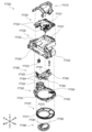
第1の部分(例えば、塔役物P7400等)と、第2の部分(例えば、振分部P7360等)と、第3の部分(例えば、特定領域ユニットP7900等)と、を備えた構造部を有する遊技機であって、
前記第1の部分は、当該第1の部分に供給された遊技球の流路(例えば、通路部P7612等)を備え、
前記第2の部分は、遊技球を前記第1の部分へ誘導する流路(例えば、通路部P7361b等)を備え、
前記第3の部分は、前記第1の部分の流路を通過した遊技球の入賞を検出可能な検出手段(例えば、センサ部P7911a等)を備え、
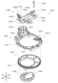
前記第1の部分は、
第1の流路(例えば、特定領域側ガイド部P7424a等)と、
前記第1の流路とは異なる第2の流路(例えば、非特定領域側ガイド部P7424b等)と、
遊技球が転動可能な傾斜する転動面を有し、当該第1の部分に供給された遊技球を前記第1の流路又は前記第2の流路へ振り分け可能な振分部(例えば、第3のステージ部P7700等)と、
前記振分部を転動する遊技球の転動方向を変更可能な転動障害部と、を備え、
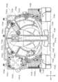
前記転動障害部は、
前記振分部を転動する遊技球と接触可能なように第1の面(例えば、垂直部P7733aの内面等)から突出する第1の突出部(例えば、突出部P7733b等)と、
前記振分部を転動する遊技球と接触可能なように前記第1の面とは異なる第2の面(例えば、第3のステージ本体P7720の転動面等)から突出する第2の突出部(例えば、突起部P7721等)と、を含み、
前記第1の突出部及び前記第2の突出部は、遊技球が前記第1の突出部と前記第2の突出部の間を通り前記転動面より下流側に移動可能なように配置され(例えば、第3のステージ本体P7720の転動面より下流側の特定領域側ガイド部P7424aまたは非特定領域側ガイド部P7424bへ移動可能なように配置されている等)、
前記転動面の外側の少なくとも一部に、前記転動面を転動する遊技球の転動方向を変更可能な移動制限部(例えば、第3のガイド部P7424の壁部分及びフレームカバー部P7411の壁部分等)を設け、
前記振分部が変位することにより、遊技球が前記転動面より下流側に移動可能となり、前記振分部の変位する位置に応じて、
遊技球が前記転動面より下流側に移動せずに前記転動面での転動を継続する場合と、
遊技球が前記転動面より下流側の前記第1の流路に移動する場合と、
遊技球が前記転動面より下流側の前記第2の流路に移動する場合と、がある、
ことを特徴とする。
The gaming machine according to the present invention comprises:
A gaming machine having a structural part including a first part (e.g., a tower role P7400, etc.), a second part (e.g., a distribution part P7360, etc.), and a third part (e.g., a specific area unit P7900, etc.),
The first portion includes a flow path (e.g., a passage portion P7612, etc.) for the game ball supplied to the first portion,
The second portion is provided with a flow path (e.g., a passage portion P7361b, etc.) that guides the game ball to the first portion,
The third section includes a detection means (e.g., a sensor unit P7911a, etc.) capable of detecting the winning of a game ball that has passed through the flow path of the first section,
The first portion is
A first flow path (for example, a specific area side guide portion P7424a, etc.),
A second flow path (for example, a non-specific region side guide portion P7424b, etc.) different from the first flow path;
A distribution section (e.g., a third stage section P7700, etc.) having an inclined rolling surface on which the game balls can roll and capable of distributing the game balls supplied to the first section to the first flow path or the second flow path;
A rolling obstacle portion capable of changing the rolling direction of the game ball rolling in the distribution portion,
The rolling obstacle portion is
A first protrusion (e.g., protrusion P7733b, etc.) protruding from a first surface (e.g., an inner surface of the vertical portion P7733a, etc.) so as to be able to come into contact with the game ball rolling on the distribution portion;
A second protruding portion (e.g., a protrusion P7721, etc.) protruding from a second surface (e.g., a rolling surface of the third stage main body P7720, etc.) different from the first surface so as to be able to come into contact with the game ball rolling on the distribution portion,
The first protrusion and the second protrusion are arranged so that the game ball can pass between the first protrusion and the second protrusion and move downstream from the rolling surface (for example, arranged so that the game ball can move to the specific area side guide portion P7424a or the non-specific area side guide portion P7424b downstream from the rolling surface of the third stage body P7720) ,
A movement limiting portion (e.g., a wall portion of the third guide portion P7424 and a wall portion of the frame cover portion P7411, etc.) capable of changing the rolling direction of the game ball rolling on the rolling surface is provided on at least a part of the outer side of the rolling surface,
By displacing the distribution part, the game ball can move downstream from the rolling surface, and depending on the position to which the distribution part is displaced,
A case where the game ball continues to roll on the rolling surface without moving downstream from the rolling surface,
When the game ball moves to the first flow path downstream of the rolling surface,
The game ball may move to the second flow path downstream of the rolling surface.
It is characterized by:
本発明によれば、遊技の興趣を向上させることができる。 The present invention can increase the enjoyment of games.
本発明の実施形態にかかる遊技機の一例として、第1のパチンコ遊技機、第2のパチン
コ遊技機および第3のパチンコ遊技機を例に挙げて説明する。
As examples of gaming machines according to the embodiments of the present invention, a first pachinko gaming machine, a second pachinko gaming machine, and a third pachinko gaming machine will be described.
なお、この明細書において、特に断りがない限り、パチンコ遊技機の正面側を前方向、
パチンコ遊技機の背面側を後方向、パチンコ遊技機を前方から見たときの左側を左方向、
パチンコ遊技機を前方から見たときの右側を右方向、パチンコ遊技機の上側を上方向、パ
チンコ遊技機の下側を下方向、パチンコ遊技機を前方から見たときの時計回りの方向を右
回り方向、その逆に反時計回りの方向を左回り方向として定義する。
In this specification, unless otherwise specified, the front side of the pachinko machine is referred to as the forward direction.
The rear side of the pachinko machine is called the rear direction, and the left side when looking at the pachinko machine from the front is called the left direction.
The right side when the pachinko game machine is viewed from the front is defined as the right direction, the upper side of the pachinko game machine as the upper direction, the lower side of the pachinko game machine as the lower direction, the clockwise direction when the pachinko game machine is viewed from the front as the rightward direction, and conversely, the counterclockwise direction as the leftward direction.
第1のパチンコ遊技機および第2のパチンコ遊技機は、いずれも、デジパチと称される
所謂1種タイプのパチンコ遊技機である。このうち、第1のパチンコ遊技機は、第1特別
図柄と第2特別図柄とが並行して可変表示可能なパチンコ遊技機である。また、第2のパ
チンコ遊技機は、第1特別図柄と第2特別図柄とが並行して可変表示されることがなくい
ずれか一方のみが可変表示されるパチンコ遊技機である。
Both the first and second pachinko gaming machines are so-called
また、第3のパチンコ遊技機は、デジパチと称される所謂1種タイプの遊技機と羽根モ
ノと称される2種タイプの遊技機とを混合した1種2種混合機と称されるパチンコ遊技機
である。この明細書で説明する第3のパチンコ遊技機も、第1特別図柄および第2特別図
柄を有するが、この明細書では、第1特別図柄と第2特別図柄とが並行して可変表示され
ることがなくいずれか一方のみが可変表示されるものを例に挙げて説明する。ただし、第
1特別図柄と第2特別図柄とが並行して可変表示可能な1種2種混合機のパチンコ遊技機
を排除する趣旨ではない。
The third pachinko machine is a pachinko machine called a
なお、この明細書において、単に「特別図柄」と称するときは、とくに言及しない限り
、第1特別図柄および第2特別図柄の両方を意味するものとする。
In this specification, when the term "special design" is used, it means both the first special design and the second special design, unless otherwise specified.
また、本明細書でいう「可変表示」とは、例えば、図柄が変動して表示される「変動表
示」、および、図柄が停止して表示される「停止表示」等の両方を含む概念であり、変動
表示の開始から停止表示されるまでの動作を1回の「可変表示」と称する。変動表示して
いる図柄が停止表示(以下、「導出」とも称する)されると、後述する特別図柄の当り判
定処理(以下、「特別図柄抽選」もと称する)の結果や普通図柄の当り判定処理(以下、
「普通図柄抽選」とも称する)の結果が確定する。なお、図柄が見掛け上は停止している
ように見えるものの、特別図柄の当り判定処理や普通図柄の当り判定処理の結果が確定し
ない態様(例えば仮停止した態様)で図柄が表示される場合もあるが、このような態様は
上記の変動表示に含まれる。なお、図柄が例えば仮停止した場合であっても、この時点で
は特別図柄の当り判定処理や普通図柄の当り判定処理の結果が確定していないため、再び
図柄を変動表示させることができる。
In addition, the term "variable display" in this specification is a concept that includes both "variable display" where the pattern is displayed by changing, and "static display" where the pattern is displayed by stopping, and the operation from the start of the variable display to the stop display is called one "variable display". When the variable display pattern is stopped (hereinafter also called "deriving"), the result of the special pattern hit determination process (hereinafter also called "special pattern lottery") described later or the normal pattern hit determination process (hereinafter also called "selection of special patterns") is displayed.
The result of the "regular symbol lottery" is determined. Note that although the symbols appear to be stopped, there are cases where the symbols are displayed in a manner in which the results of the special symbol hit determination process and the regular symbol hit determination process are not yet determined (for example, a provisionally stopped state), and such a manner is included in the variable display described above. Note that even if the symbols are temporarily stopped, for example, the results of the special symbol hit determination process and the regular symbol hit determination process are not yet determined at this point, so the symbols can be displayed again in a variable manner.
また、この明細書において、第1のパチンコ遊技機、第2のパチンコ遊技機および第3
のパチンコ遊技機を説明するにあたり、いずれも特別図柄の数が2つ(第1特別図柄、第
2特別図柄)の場合を例に挙げて説明する。ただし、第2のパチンコ遊技機および第3の
パチンコ遊技機については、特別図柄の数は1つであっても良い。
In addition, in this specification, a first pachinko gaming machine, a second pachinko gaming machine and a third pachinko gaming machine
In explaining the pachinko gaming machine of the above, the case where the number of special symbols is two (first special symbol and second special symbol) will be explained as an example. However, the number of special symbols may be one for the second pachinko gaming machine and the third pachinko gaming machine.
[1.第1のパチンコ遊技機]
先ず、第1のパチンコ遊技機について説明する。
[1. The first pachinko game machine]
First, the first pachinko gaming machine will be described.
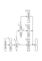
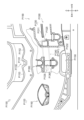
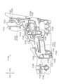
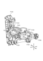
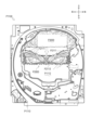
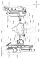
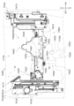
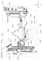
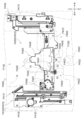
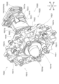
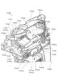
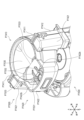
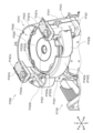
[1-1.外観構成]
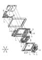
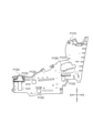
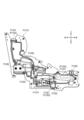
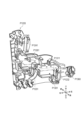
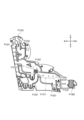
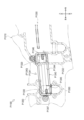
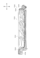
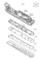
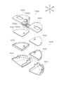
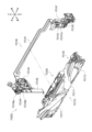
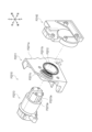
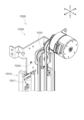
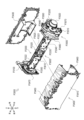
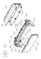
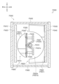
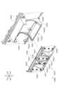
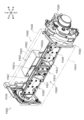
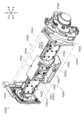
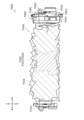
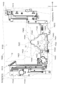
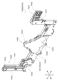
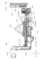
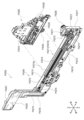
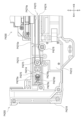
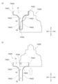
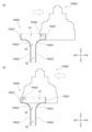
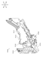
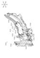
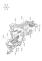
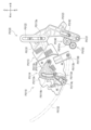
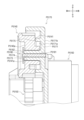
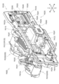
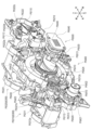
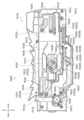
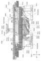
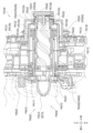
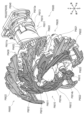
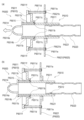
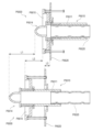
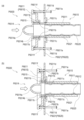
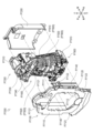
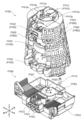
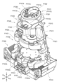
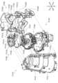
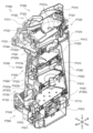
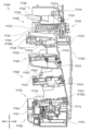
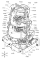
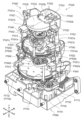
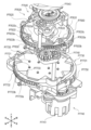
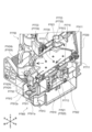
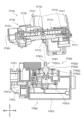
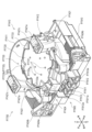
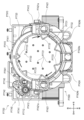
図1は、第1のパチンコ遊技機を前方向右斜め上から見たときの外観を示す斜視図の一
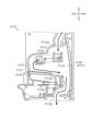
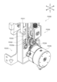
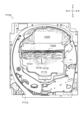
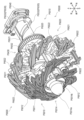
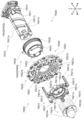
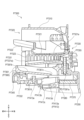
例である。図2は、第1のパチンコ遊技機を前方向右斜め上から見たときの分解斜視図の
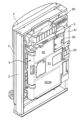
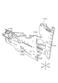
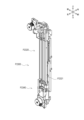
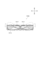
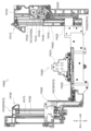
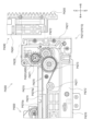
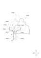
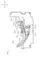
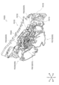
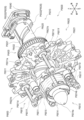
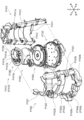
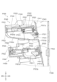
一例である。図3は、第1のパチンコ遊技機を後方向右斜め上から見たときの外観を示す
斜視図の一例である。
[1-1. Appearance]
Fig. 1 is an example of a perspective view showing the appearance of the first pachinko gaming machine when viewed from diagonally above the front right. Fig. 2 is an example of an exploded perspective view of the first pachinko gaming machine when viewed from diagonally above the front right. Fig. 3 is an example of a perspective view showing the appearance of the first pachinko gaming machine when viewed from diagonally above the rear right.
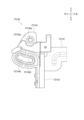
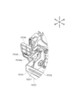
[1-1-1.基本構成]
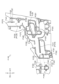
図1~図3に示されるように、第1のパチンコ遊技機は、外枠2、ベースドア3、ガラ
スドア4、皿ユニット5、発射装置6、表示装置7(図2参照)、払出ユニット8(図2
、図3参照)、基板ユニット9(図2、図3参照)、および、遊技盤ユニット10(図2
参照)等を備える。さらに、遊技盤ユニット10の右下部にはLEDユニット160(図
2参照)が設けられている。ここでは、外枠2、ベースドア3、ガラスドア4、皿ユニッ
ト5、発射装置6、表示装置7、払出ユニット8および基板ユニット9について簡単に説
明し、遊技盤ユニット10およびLEDユニット160についての詳細を後述する。なお
、上記の括弧書きは、図1に図示がない構成についての参照図面を示している。
[1-1-1. Basic configuration]
As shown in FIGS. 1 to 3, the first pachinko gaming machine includes an
3), a board unit 9 (see FIGS. 2 and 3), and a game board unit 10 (see FIG. 2
In addition, an LED unit 160 (see FIG. 2) is provided at the lower right of the
(外枠)
外枠2は、正面視略矩形状の枠体であり、前後方向に貫通する開口21を有する。この
外枠2は、遊技場の島設備に固定して取り付けられる。外枠2の例えば左端部の前側には
蝶番(参照符号なし)が設けられており、この蝶番には、ベースドア3が軸支されている
。このようにすることで、蝶番を軸として外枠2に対してベースドア3を前方に回動させ
ることが可能となっている。
(Outer frame)
The
なお、外枠2は、ベースドア3を介して、後述する払出ユニット8、基板ユニット9、
表示装置7、遊技盤ユニット10、ガラスドア4および皿ユニット5等の多数の部材を支
持するため、高い強度が必要とされる。その一方で、演出効果を高めることを目的として
例えば表示装置7(図2参照)や遊技盤ユニット10の大型化が要求されている。そのた
め、外枠2を例えば薄板の金属で構成することにより、表示装置7や遊技盤ユニット10
の大型化を図りつつ、高い強度を保つことができる。とくに外枠2をアルミ製にすれば、
軽量化を図ることも可能となる。
The
High strength is required to support many components such as the
It is possible to increase the size while maintaining high strength. In particular, if the
It is also possible to reduce weight.
(ベースドア)
ベースドア3は、裏面側に例えば払出ユニット8および基板ユニット9等が取り付けら
れており、これらを支持している。
(Base door)
The
ベースドア3の表面側には遊技盤ユニット10がはめ込まれる。また、ベースドア3の
例えば左端部の前側には、上端部、上下方向略中央部よりも下方側の中途部、および、下
端部のそれぞれに蝶番(参照符号なし)が設けられており、上端部および中途部の蝶番に
ガラスドア4が軸支され、中途部および下端部の蝶番に皿ユニット5がそれぞれ軸支され
ている。このようにすることで、蝶番を軸としてベースドア3に対してガラスドア4およ
び皿ユニット5を一体でまたは個別に前方に回動させることが可能となっている。
A
また、ベースドア3の表面側の例えば右側下方には発射装置6が固定して取り付けられ
ており、例えば上方側の左右のそれぞれには、スピーカ32(図2参照)が固定して取り
付けられている。このスピーカ32からは、例えば、表示装置7に表示されるキャラクタ
等の音声演出、楽曲、効果音、音声による告知、エラー報知等の演出音等が出力される。
The
さらに、ベースドア3の蝶番と反対側(すなわち右端部)には、施錠装置(不図示)が
設けられている。この施錠装置は、外枠2に対してベースドア3を施錠したり、ベースド
ア3に対してガラスドア4を施錠したりする機能を備えている。
Furthermore, a locking device (not shown) is provided on the opposite side (i.e., the right end) of the
(ガラスドア)
ガラスドア4は、開口41が形成された枠状の部材である。この開口41には、透過性
を有する保護ガラス43(図2参照)が後面側から取り付けられている。ガラスドア4が
ベースドア3に対して閉じられると、遊技盤ユニット10に形成される遊技領域105(
後述の図4参照)と保護ガラス43とが対向する。このようにして、ガラスドア4がベー
スドア3に対して閉じられた状態で遊技領域105を前方から視認することができるとと
もに、遊技領域105を流下する遊技球が前方に飛び出さないようにすることができる。
(Glass door)
The
4 described later) faces the
なお、保護ガラス43は、複数枚(例えば2枚)のガラスを互いに間隙を有して取り付
けるものであってもよいし、互いに間隙を有するように複数枚のガラスがユニット化され
たものであってもよい。さらには、ユニット化されたものである場合、ガラスとガラスと
の間に例えば導光板が備えられたものであってもよい。上記の保護ガラス43は、ガラス
製に限られず、例えば透明樹脂製であってもよい。
The
また、ガラスドア4の下部には、遊技情報提供サービス(例えば、「ユニメモ(登録商
標)」)の提供を受けるために例えば遊技者が操作することが可能な操作部66が設けら
れる。この操作部66は、遊技場の管理者等がホールメニュー画面上で操作することが可
能な操作部として機能させることもできる。
In addition, an
また、ガラスドア4の上部には、上述したスピーカ32の前方に配置されるスピーカカ
バー45が設けられている。さらに、ガラスドア4の開口41の周縁部には、発光演出等
に用いられる多数のLED群46が配置されており、これらのLED群46の前方にはL
EDカバーが設けられている。図1および図2において図示される符号46は、厳密にい
えばLEDカバーであるが、便宜上、LED群46として説明する。LED群46は、例
えば、光での告知や、さまざまなバリエーションで発光演出等を行う演出用の発光手段で
あるが、このような発光演出等を実行できればLEDに限られず、例えば液晶やランプ等
であってもよい。
A
1 and 2 is an LED cover, strictly speaking, but for convenience, it will be described as an
(皿ユニット)
皿ユニット5は、上皿51と下皿52とをユニット化したものである。皿ユニット5は
、ベースドア3の前下部であって、ガラスドア4の下方に配置される。この皿ユニット5
は、例えば球詰まり等の発生時に遊技場の店員等が球詰まりを解消できるように、上述し
たとおり、ベースドア3に対して回動させて開閉できるように構成されている。なお、皿
ユニット5は、必ずしも上皿51と下皿52とをそれぞれ設ける必要はなく、一体皿とし
て構成してもよい。
(Dish unit)
The
As described above, the
上皿51は、遊技球を貯留可能に設けられており、上皿51に貯留された遊技球は、発
射装置6から遊技領域105(後述の図4参照)に向けて発射される。上皿51には、払
出口53および演出ボタン54等が設けられる。貸し出される遊技球や賞球として払い出
される遊技球は、払出口53から上皿51に払い出される。演出ボタン54は、所謂「C
HANCEボタン」や、「プッシュボタン」等と呼ばれるものである。演出ボタン54は
、遊技者によって操作される操作機能の他、所定の演出機能を有してもよい。所定の演出
機能としては、例えば特別図柄の当り判定処理の結果に基づいて振動したり上方に突出す
るような機能が相当する。また、上記操作部66の機能を兼用するようにしてもよい。
The
This is called a "HANCE button" or a "push button". The
下皿52は、主として上皿51から溢れた遊技球を貯留するためのものである。下皿5
2には上皿51と連通する払出口55が設けられており、上皿51から溢れた遊技球は払
出口55から下皿52に払い出される。
The
2 is provided with a
下皿52の底面には、遊技者の操作によって開閉させることが可能な開口部(参照符号
なし)が形成されている。下皿52の底面に形成された開口部を開状態にすると、下皿5
2に貯留されている遊技球を、下皿52の下方に載置された球箱に移すことができる。な
お、所謂各台計数システムが各台に設けられている場合、球箱を必要としないだけでなく
、各台計数システムで計数された遊技球を貯球し、貯球された遊技球を再び遊技に供する
こともできる。
An opening (without a reference symbol) that can be opened and closed by the player is formed on the bottom surface of the
The game balls stored in the
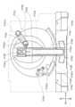
(発射装置)
発射装置6は、上皿51に貯留された遊技球を、遊技領域105(後述の図4参照)に
向けて発射するためのものである。発射装置6は、ベースドア3の前右下部であって、皿
ユニット5の右下方に配置される。発射装置6は、パネル体61、駆動装置(不図示)お
よび発射ハンドル62を備える。
(Launch device)
The
パネル体61は、ベースドア3に対し皿ユニット5が閉じられた状態において、皿ユニ
ット5と、ベースドア3に固定して取り付けられた発射装置6とが外観上一体となるよう
に設けられる。
The
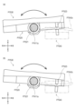
発射ハンドル62は、右回りまたは左回りに回動可能に構成されており、パネル体61
の表面側に配置される。上記の駆動装置は、パネル体61の裏面側に配置され、例えば発
射ソレノイド(図示せず)により構成される。遊技者によって発射ハンドル62が操作さ
れると、駆動装置の動作により遊技球が発射される。なお、発射ハンドル62を操作する
際に、右回りへの回動量(操作量)が大きいほど遊技球の発射強度が強くなる。
The firing handle 62 is configured to be rotatable clockwise or counterclockwise.
The drive device is disposed on the front side of the
皿ユニット5の右下方に配置された発射装置6から発射された遊技球は、発射レール(
不図示)を経てガイドレール110(後述の図4参照)に沿って円弧状に転動して遊技領
域105(後述の図4参照)に打ち出される。なお、発射装置6の配置位置は、皿ユニッ
ト5の右下方に限られず、皿ユニット5の左下方であってもよい。この場合、上記の発射
レールが不要となり、ガラスドア4の下方の領域を有効に利用することができ、汎用性を
高めることが可能となる。
The game balls launched from the
The balls pass through a guide rail 110 (not shown) and roll in an arc along the guide rail 110 (see FIG. 4 described later) to be launched into the play area 105 (see FIG. 4 described later). The location of the
(表示装置)
表示装置7(図2参照)は、遊技に関する各種の演出画像を表示する表示領域を有する
ものであって、遊技パネル100の開口に上記の表示領域が臨むように取り付けられる。
表示装置7は、例えば、液晶表示装置、7セグ表示装置、ドットマトリクス表示装置、エ
レクトロルミネッセンスで構成される表示装置等であってもよいし、プロジェクタ等の投
影装置を用いて映像を投影するものであってもよい。表示装置7の表示領域には、例えば
、演出用識別図柄(例えば、装飾図柄)を可変表示させて特別図柄の当り判定処理の結果
を表示したり、特別図柄の当り判定処理の結果に応じた演出画像、大当り遊技状態中の演
出画像、デモ演出画像、特別図柄の可変表示の保留状況を示す演出画像等が表示される。
本実施例では、表示装置7が遊技盤ユニット10に取り付けられているが、表示装置7の
表示領域が遊技パネル100の開口に臨むように配置されていれば、表示装置7はベース
ドア3に取り付けられるようにしてもよい。
(Display Device)
The display device 7 (see FIG. 2) has a display area for displaying various presentation images related to the game, and is attached to the
The
In this embodiment, the
なお、本実施例では、上記各種の演出画像を表示するものとして一つの表示装置7を備
えているが、複数(例えば二つ)の表示装置を設けて、これら複数の表示装置を用いて演
出画像を表示するようにしても良い。
In this embodiment, one
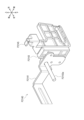
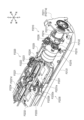
(払出ユニット)
払出ユニット8(図2、図3参照)は、ベースドア3の背面側に配置されており、球通
路81、払出装置82等で構成される。球通路81には、貯留タンク80(図2、図3参
照)から遊技球が供給される。なお、貯留タンク80には、島設備(不図示)から遊技球
が供給される。払出装置82は、払出条件が成立すると、貯留タンク80から球通路81
に供給された遊技球のうち所定個数の遊技球を例えば上皿51に払い出す。また、払出ユ
ニット8の背面側には、図3に示されるように電源スイッチ95が設けられる。
(Payout unit)
The payout unit 8 (see Figures 2 and 3) is disposed on the rear side of the
Of the game balls supplied to the
(基板ユニット)
基板ユニット9(図2、図3参照)は、ベースドア3の背面側に配置される。基板ユニ
ット9には、各種制御基板等が設けられる。
(Board unit)
The board unit 9 (see Figs. 2 and 3) is disposed on the rear side of the
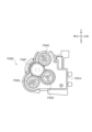
具体的には、図3に示されるように、主制御回路200(後述の図6参照)が実装され
た主制御基板91、サブ制御回路300(後述の図6参照)が実装されたサブ制御基板9
2、遊技球の払出・発射を制御する払出・発射制御回路400(後述の図6参照)が実装
された払出・発射制御基板93、および、電源を供給する電源供給回路450(後述の図
6参照)が実装された電源供給基板等が基板ユニット9に設けられている。
Specifically, as shown in FIG. 3, a
2. The
なお、図3では、便宜上、主制御基板91、サブ制御基板92、払出・発射制御基板9
3および電源供給基板94を参照符号として示しているが、これらの基板は、全て、基板
ケースに収容されている。
In FIG. 3, for convenience, a
3 and a power supply board 94 are shown by reference numerals, and these boards are all housed in a board case.
また、本実施例では、サブ制御基板92を、ワンボード基板(1つの基板に1つの制御
LSIまたは複数のLSIが設けられた基板)として構成する。ただし、これに限られず
、例えば、後述する表示制御回路304、音声制御回路305、LED制御回路306お
よび役物制御回路307(いずれも後述の図6参照)等の全部または一部を別個の基板と
することで、サブ制御基板92を複数の基板で構成してもよい。
In this embodiment, the
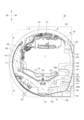
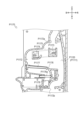
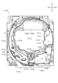
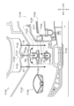
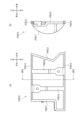
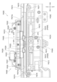
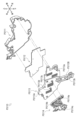
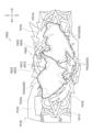
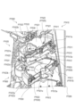
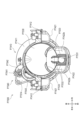
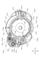
[1-1-2.遊技盤ユニット]
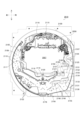
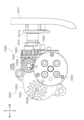
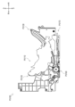
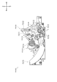
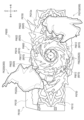
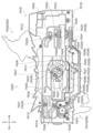
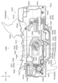
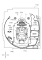
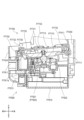
図4は、第1のパチンコ遊技機が備える遊技盤ユニット10の外観を示す正面図の一例
である。
[1-1-2. Game board unit]
FIG. 4 is an example of a front view showing the appearance of the
図4に示されるように、遊技盤ユニット10は、主として、発射された遊技球が転動流
下可能な遊技領域105が形成される遊技パネル100と、ガイドレール110と、遊技
領域105の略中央部に配置されるセンター役物115と、第1始動口120と、一般入
賞口122と、通過ゲートユニット125と、特別電動役物ユニット130と、第2始動
口140A,140Bと、普通電動役物ユニット145と、小当りユニット150と、L
EDユニット160と、アウト口178と、遊技盤ユニット10の後方に配置される裏ユ
ニット(図示せず)とを備える。なお、上述したとおり、LEDユニット160について
は後述する。
As shown in FIG. 4, the
The
(遊技パネル)
遊技パネル100には、表示装置7の表示領域が臨む位置に開口(参照符号なし)が形
成されている。また、遊技パネル100の前面には、ガイドレール110が設けられると
ともに遊技釘(参照符号なし)等が植設されている。発射装置6(図1、図2参照)から
発射された遊技球は、ガイドレール110から遊技領域105に向けて飛び出し、遊技釘
等と衝突して進行方向を変えながら遊技領域105の下方に向けて流下する。
(Game panel)
An opening (no reference number) is formed in the
また、遊技パネル100の後方には、演出効果を高めるために装飾体が設けられた裏ユ
ニット(図示せず)が配置されている。遊技パネル100は、裏ユニットに設けられた装
飾体を正面視で視認できるように透明樹脂で構成されている。この場合、遊技パネル10
0の全部が透明部材で構成されていてもよいし、例えば、裏ユニットに設けられた装飾体
を正面視で視認できる部位のみが透明部材で構成されていてもよい。また、遊技パネル1
00を、透明部分を有さない部材(例えば木製)で構成し、一部に透明部材を設けて演出
効果を高めるようにしてもよい。
In addition, a back unit (not shown) on which a decorative body is provided to enhance the presentation effect is disposed behind the
The entirety of the
00 may be constructed from materials that do not have transparent parts (e.g., wood), with transparent materials provided in some areas to enhance the presentation effect.
なお、本実施例では、裏ユニットを正面視で視認できるように遊技パネル100が透明
樹脂で構成されているが、遊技パネル100の全部を透明としてもよいし、一部のみを透
明としてもよい。
In this embodiment, the
(ガイドレール)
ガイドレール110は、円弧状の外レールおよび内レール(いずれも参照符号なし)に
より構成される。遊技領域105は、ガイドレール110によって区画(画定)される。
外レールおよび内レールは、発射装置6から発射された遊技球を遊技領域105の上部に
案内する機能を有する。
(Guide rail)
The
The outer rail and the inner rail have the function of guiding the game ball launched from the
(センター役物)
センター役物115は、遊技パネル100の開口にはめ込まれるように構成されており
、上方には円弧状のセンターレール116を備えている。遊技領域105に向けて発射さ
れた遊技球は、センターレール116によって左右に振り分けられる。
(Center role)
The
この第1のパチンコ遊技機において、遊技領域105のうち、センター役物115より
も左側の領域を左側領域106と称し、センター役物115よりも右側の領域を右側領域
107と称する。左側領域および右側領域の定義は、後述する第2のパチンコ遊技機およ
び第3のパチンコ遊技機についても同様である。
In this first pachinko gaming machine, the area of the
発射装置6によって遊技領域105に向けて発射された遊技球は、左側領域106また
は右側領域107を流下する。左側領域106または右側領域107を流下する遊技球は
、遊技パネル100に植設された遊技釘等との衝突により、進行方向を変えながら下方へ
向けて流下する。発射ハンドル62の操作量が小さい場合、発射された遊技球は左側領域
106を流下する。一方、発射ハンドル62の操作量が大きい場合、発射された遊技球は
右側領域107を流下する。
A game ball launched by the
なお、この明細書において、発射ハンドル62の操作態様(打ち方)として、左側領域
106を流下するように遊技球を発射させる打ち方を「左打ち」と称し、右側領域107
を流下するように遊技球を発射させる打ち方を「右打ち」と称する。このように、遊技者
によって左側領域106または右側領域107に向けて遊技球を打ち分け可能とされてい
る。
In this specification, as an operation mode (hitting method) of the
The hitting style in which the game ball is shot so as to flow down the
また、センター役物115には、左側の外周縁部に、左側領域106を流下する遊技球
が進入可能とされたワープ入口117が形成されている。ワープ入口117に進入した遊
技球は、センター役物115に形成されたステージ118に誘導可能に構成されている。
ステージ118は、表示装置7の表示領域の下方前方において遊技球が左右方向に転動可
能に形成されている。なお、ステージ118は、例えば、上段側のステージおよび下段側
のステージといったように、複数段で形成されていてもよい。
In addition, a
The
ステージ118の左右方向略中央の後側には、遊技球が進入可能なチャンス入口119
が形成されており、チャンス入口119に進入した遊技球は、第1始動口120の直上に
放出されるように構成されている。そのため、チャンス入口119に進入した遊技球は、
ワープ入口117に進入しなかった遊技球や、ワープ入口117に進入したもののチャン
ス入口119に進入しなかった遊技球と比べて高い確率で第1始動口120に入賞(通過
)するようになっている。
At the rear of the
is formed, and the game ball that enters the
The probability of the game ball entering (passing) the
(第1始動口)
第1始動口120は、表示装置7の表示領域の下方に配置されており、左打された遊技
球が入賞可能(右打ちされた遊技球が入賞困難または不可能)となるように配置されてい
る。第1始動口120に遊技球が入賞すると、第1始動口スイッチ121(後述の図6参
照)により検出される。なお、右打ちされた遊技球が第1始動口120に入賞可能であっ
てもよい。また、上記の第1始動口120に代えてまたは加えて、右打ちされた遊技球が
入賞可能(左打ちされた遊技球が入賞困難または不可能)な第1始動口を備えるようにし
てもよい。
(First starting point)
The
第1始動口スイッチ121(後述の図6参照)により第1始動口120への遊技球の入
賞(通過)が検出されると、第1特別図柄にかかる各種データ(例えば、第1特別図柄の
大当り判定用乱数値、第1特別図柄の図柄乱数値、第1特別図柄のリーチ判定用乱数値、
および、第1特別図柄の演出選択用乱数値等の各種乱数値等)が抽出され、抽出された各
種データは所定数(例えば最大4個)まで記憶される。記憶された各種データは、始動条
件が成立すると、第1特別図柄の当り判定処理に供される。第1始動口120に遊技球が
入賞すると例えば3個の賞球が払い出される。ただし、第1始動口120への遊技球の入
賞に基づいて払い出される賞球数はこれに限られない。
When the first start hole switch 121 (see FIG. 6 described later) detects the entry (passage) of a game ball into the
and various random numbers such as a random number for selecting the effect of the first special symbol) are extracted, and the various extracted data are stored up to a predetermined number (for example, up to four). When the start condition is met, the various stored data are used for the winning determination process of the first special symbol. When a gaming ball enters the
この明細書において、第1始動口120への遊技球の入賞を第1特別図柄の始動入賞と
称し、第1特別図柄にかかる各種データ(例えば、第1特別図柄の大当り判定用乱数値、
第1特別図柄の図柄乱数値、第1特別図柄のリーチ判定用乱数値、および、第1特別図柄
の演出選択用乱数値等の各種乱数値等)を第1特別図柄の始動情報と称する。また、始動
条件が成立するまで第1特別図柄の始動情報を記憶することを保留と称し、保留されてい
る第1特別図柄の始動情報を「第1特別図柄の保留球」とも称する。第2特別図柄につい
ても同様である。
In this specification, the entry of a gaming ball into the
The random numbers, such as the random number of the first special symbol, the random number for reach judgment of the first special symbol, and the random number for performance selection of the first special symbol, are referred to as the start information of the first special symbol. In addition, storing the start information of the first special symbol until the start condition is established is referred to as reservation, and the reserved start information of the first special symbol is also referred to as the "reserved ball of the first special symbol." The same applies to the second special symbol.
(一般入賞口)
一般入賞口122は、遊技領域105の左下方に複数配置されており、左打された遊技
球が入賞可能(右打ちされた遊技球が入賞困難または不可能)となるように配置されてい
る。一般入賞口122に遊技球が入賞すると、一般入賞口スイッチ123(後述の図6参
照)により検出される。
(General prize entry)
The general winning
一般入賞口スイッチ123(後述の図6参照)により一般入賞口122への遊技球の入
賞(通過)が検出されると、例えば4個の賞球が払い出されるが、一般入賞口122への
遊技球の入賞に基づいて払い出される賞球数は4個に限られない。
When the general prize opening switch 123 (see Figure 6 described below) detects the entry (passage) of a game ball into the
また、本実施例において、一般入賞口122は、右打ちされた遊技球が入賞困難または
不可能となるように配置されているが、必ずしもこれに限られず、上記の一般入賞口12
2に代えてまたは加えて、右打ちされた遊技球が入賞可能な一般入賞口を備えてもよい。
In this embodiment, the general winning
In place of or in addition to 2, a general winning hole may be provided through which a game ball hit to the right can win a prize.
(通過ゲートユニット)
通過ゲートユニット125は、右側領域107に配置されており、右打ちされた遊技球
がほぼ通過できるように構成された通過ゲート126と、通過ゲート126への遊技球の
通過を検出する通過ゲートスイッチ127(後述の図6参照)とを一体化したユニット体
である。
(Passing gate unit)
The
通過ゲートスイッチ127により通過ゲート126への遊技球の通過が検出されると、
普通図柄にかかる各種データ(例えば、普通図柄の当り判定用乱数値等)が抽出され、抽
出された各種データは所定数(例えば最大4個)まで記憶される。記憶された各種データ
は、普通図柄の当り判定処理に供される。なお、通過ゲートスイッチ127により通過ゲ
ートユニット125への遊技球の通過が検出されたとしても、賞球は払い出されない。ま
た、通過ゲートユニット125は、右側領域107に代えてまたは加えて左側領域106
に配置されていてもよい。
When the passing
Various data related to the normal symbols (e.g., random numbers for determining whether a normal symbol is a winning symbol, etc.) are extracted, and the extracted various data are stored up to a predetermined number (e.g., up to four). The stored various data are used for the process of determining whether a normal symbol is a winning symbol. Even if the passing
may be arranged in
また、通過ゲート126を、役物連続作動装置を作動させるための契機となるように機
能させてもよい。すなわち、大当りでない遊技状態(例えば通常遊技状態等)から大当り
遊技状態への移行条件は、条件装置および役物連続作動装置の両方が作動することである
が、大当りであることを示す停止表示態様(図柄組合せ)が導出された際に、条件装置に
ついては作動させるものの役物連続作動装置については作動させないようにすることがで
きる。そして、条件装置が作動していることを前提として、通過ゲート126への遊技球
の通過すなわち通過ゲートスイッチ127(後述の図6参照)により遊技球が検出された
ことをもって役物連続作動装置を作動させて、大当り遊技状態に移行するようにしてもよ
い。
The
この明細書において、通過ゲート126への遊技球の通過を始動通過と称し、通過ゲー
ト126への遊技球の通過によって抽出された普通図柄にかかる各種データ(例えば、普
通図柄の当り判定用乱数値等)を普通図柄の始動情報と称する。また、始動条件が成立す
るまで普通図柄の始動情報を記憶することを保留と称し、保留されている普通図柄の始動
情報を「普通図柄の保留球」とも称する。
In this specification, the passage of the game ball through the passing
(特別電動役物ユニット)
特別電動役物ユニット130は、大当り用大入賞口131と、大当り用大入賞口131
への遊技球の入賞(通過)を検出する大当り用大入賞口カウントスイッチ132(後述の
図6参照)と、特別電動役物133とを一体化したユニット体である。特別電動役物ユニ
ット130は、遊技領域105内の略右下部であって、通過ゲートユニット125よりも
下方に配置されている。
(Special electric feature unit)
The special
The special
大当り用大入賞口131は、右打ちされた遊技球が入賞可能(左打ちされた遊技球が入
賞困難または不可能)となるように配置されている。ただし、これに限定されるものでは
なく、上記の大当り用大入賞口131に代えてまたは加えて、左打ちされた遊技球が入賞
可能な大当り用大入賞口を配置したり、センター役物115の上部において遊技球が入賞
可能な大当り用大入賞口を配置するようにしてもよい。
The
また、大当り用大入賞口131は、遊技者に有利な遊技状態である大当り遊技状態に制
御されているときに所定個数(例えば10個)の遊技球が入賞(通過)可能となるように
開放される入賞口である。大当り用大入賞口カウントスイッチ132(後述の図6参照)
により大当り用大入賞口131への遊技球の入賞が検出されると、例えば10個の賞球が
払い出される。ただし、大当り用大入賞口131への遊技球の入賞に基づいて払い出され
る賞球数は10個に限られない。
The
When the entry of a game ball into the big winning
特別電動役物133は、前後方向に進退可能な特電用シャッタ134と、この特電用シ
ャッタ134を作動させる特電用ソレノイド135(後述の図6参照)とを備える。特別
電動役物133すなわち特電用シャッタ134は、大当り用大入賞口131への遊技球の
入賞(通過)が可能または容易な開放状態と、大当り用大入賞口131への遊技球の入賞
(通過)が不可能または困難な閉鎖状態と、に状態移行可能に構成される。なお、大当り
用大入賞口131の閉鎖状態から開放状態への状態移行は、所定のラウンド数にわたって
行われる。すなわち、大当り遊技状態は、大当り用大入賞口131が閉鎖状態から所定期
間にわたって開放状態に移行するラウンド遊技を複数ラウンドにわたって行うことにより
、多量の遊技球を賞球として払い出すことを可能にした遊技状態である。
The special
(第2始動口)
本実施例では、第2始動口として、第2始動口140Aおよび第2始動口140Bが遊
技領域105に配置されており、これらの第2始動口140A,140Bは、いずれも、
右打された遊技球が入賞可能(左打ちされた遊技球が入賞困難または不可能)となってい
る。ただし、これに限られず、左打ちされた遊技球が第2始動口140Aまたは/および
第2始動口140Bに入賞可能であってもよい。
(Second starting hole)
In this embodiment, the
A game ball hit to the right can win a prize (a game ball hit to the left has difficulty or cannot win a prize). However, this is not limited to this, and a game ball hit to the left may be able to win a prize in the
第2始動口140Aに遊技球が入賞すると、第2始動口スイッチ141A(後述の図6
参照)により検出される。また、第2始動口140Bに遊技球が入賞すると、第2始動口
スイッチ141B(後述の図6参照)により検出される。第2始動口140A,140B
のいずれに遊技球が入賞したとしても、第2特別図柄の当り判定処理の契機となる。
When the game ball enters the
When the game ball enters the
Regardless of which of the above the game ball lands on, it triggers the process of determining whether or not the second special symbol has been won.
第2始動口スイッチ141A,141B(後述の図6参照)により第2始動口140A
,140Bへの遊技球の入賞(通過)が検出されると、第2特別図柄の始動情報が抽出さ
れ、抽出された始動情報は所定数(例えば最大4個)まで保留される。保留された始動情
報は、第2特別図柄の当り判定処理に供される。第2始動口140Aに遊技球が入賞する
と例えば3個の賞球が払い出される。一方、第2始動口140Bに遊技球が入賞すると例
えば1個の賞球が払い出される。ただし、第2始動口140A,140Bへの遊技球の入
賞に基づいて払い出される賞球数はこれに限られない。
The
When the entry (passage) of a game ball into
ところで、本実施例では、右打ちされたものの大当り用大入賞口131に入賞しなかっ
た遊技球の流下方向としての下流側には、遊技球の流下経路として上下に2つの流下経路
107a,107bが形成されている。右打ちされて大当り用大入賞口131に入賞せず
にさらに下流側に向けて流下した遊技球は、例えば図4に示される分岐釘108によって
、上方の流下経路107aまたは下方の流下経路107bに振り分けられる。
In this embodiment, two
第2始動口140Aは、上方の流下経路107aに振り分けられた遊技球が入賞可能に
配置されており、上方の流下経路107aを流下する遊技球の殆どが入賞可能となってい
る。ただし、上方の流下経路107aを流下する遊技球の殆どが第2始動口140Aに入
賞するように構成することは必須ではなく、例えば、第2始動口140Aへの入賞が殆ど
期待できない構成であってもよいし、上方の流下経路107aを流下する遊技球のうち所
定の期待値(例えば、概ね3分の1~5分の1)で入賞可能な構成であってもよい。なお
、上方の流下経路107aを流下したものの第2始動口140Aに入賞しなかった遊技球
は、アウト口178から機外に排出されるように構成されている。
The
第2始動口140Bは、下方の流下経路107bに振り分けられた遊技球が入賞可能に
配置されているが、その詳細については普通電動役物ユニット145の説明において後述
する。
The
(普通電動役物ユニット)
普通電動役物ユニット145は、下方の流下経路107b側に配置されており、遊技球
が入賞(通過)することによって所定数の遊技球が賞球として払い出される入賞口と、こ
の入賞口への遊技球の入賞を検出するスイッチと、普通電動役物146とを一体化したユ
ニット体である。本実施例では、上記の入賞口を第2始動口140Bとし、上記のスイッ
チを第2始動口スイッチ141Bとしている。ただし、上記の入賞口を第2始動口140
Bとすることは必須ではなく、例えば第1始動口を上記の入賞口としてもよい。
(Normal electric role unit)
The normal
It is not essential to use B, and for example, the first starting hole may be the winning hole.
普通電動役物146は、前後方向に進退可能な普電用シャッタ147と、この普電用シ
ャッタ147を作動させる普電用ソレノイド148(後述の図6参照)とを備える。普通
電動役物146すなわち普電用シャッタ147は、第2始動口140Bへの遊技球の入賞
(通過)が可能または容易な開放状態と、第2始動口140Bへの遊技球の入賞が不可能
または困難な閉鎖状態と、に状態移行可能に構成される。なお、前後方向に進退可能な上
記の普電用シャッタ147に代えて、所謂電動チューリップと呼ばれる例えば一対の羽根
部材からなる可動部材を採用してもよい。また、可動部材は、一対に限られず、羽根型、
扉型、突出板型等を含む。
The normal
Includes door type, protruding plate type, etc.
(小当りユニット)
小当りユニット150は、小当り用大入賞口151と、小当り用大入賞口151への遊
技球の入賞(通過)を検出する小当り用大入賞口カウントスイッチ152(後述の図6参
照)と、前後方向に進退可能な小当り用シャッタ153と、この小当り用シャッタ153
を作動させることが可能な小当り用ソレノイド154とを一体化したユニット体である。
(Small hit unit)
The
It is a unit body that integrates a
小当り用シャッタ153は、前後方向に進退させることで、小当り用大入賞口151へ
の遊技球の入賞(通過)が可能または容易な開放状態と、小当り用大入賞口151への遊
技球の入賞が不可能または困難な閉鎖状態と、に状態移行可能に構成される。
The
小当り用大入賞口151が開放されたときに遊技球が入賞すると、入賞した遊技球が小
当り用大入賞口カウントスイッチ152(後述の図6参照)に検出される。小当り用大入
賞口カウントスイッチ152に遊技球が検出されると、例えば10個の賞球が払い出され
る。ただし、小当り用大入賞口151への遊技球の入賞に基づいて払い出される賞球数は
10個に限られない。
When the small win
また、小当りユニット150は、下方の流下経路107bであって普通電動役物ユニッ
ト145の下流側に配置されている。したがって、普通電動役物146の作動によって第
2始動口140Bが開放されている場合、たとえ小当り用大入賞口151が開放されてい
たとしても、下方の流下経路107bを流下した遊技球は小当り用大入賞口151に到達
する前に、上流側に設けられる第2始動口140Bに入賞するため、小当り用大入賞口1
51に入賞することが困難(または不可能)となる。
In addition, the small winning
It becomes difficult (or impossible) to score 51.
なお、本実施例では、大当り用大入賞口131と小当り用大入賞口151とをそれぞれ
別に設けているが、これに限られず、大当り遊技制御処理の実行時に開放される大入賞口
と、小当り遊技制御処理の実行時に開放される大入賞口とを、同じ大入賞口としてもよい
。
In this embodiment, the
(アウト口)
アウト口178は、遊技領域105に向けて発射されたものの各種入賞口(例えば、第
1始動口120、第2始動口140A,140B、大当り用大入賞口131、一般入賞口
122等)のいずれにも入賞しなかった遊技球を、機外に排出するためのものである。こ
のアウト口178は、左打ちされた遊技球および右打ちされた遊技球のいずれについても
機外に排出できるように、遊技領域105の最下流側に設けられている。ただし、上記の
アウト口178に加えて、最下流側でない位置、例えば複数の一般入賞口122の間や普
通電動役物ユニット145と小当りユニット150との間等にアウト口を設けて、遊技領
域105を流下中の遊技球を機外に排出するようにしてもよい。
(Outlet)
The
(裏ユニット)
裏ユニット(不図示)は、装飾体を有するものであって、上述したように、透過性のあ
る遊技パネル100の後方側に設けられる。この裏ユニットは、サブ制御回路300(後
述の図6参照)によって制御される可動役物等の演出用役物群58を備える。演出用役物
群58は、表示装置7の表示領域の周囲に配置される。これらの演出用役物群58のうち
少なくとも一以上の役物または役物を構成する演出用役物構成部材は、特別図柄の当り判
定処理の結果にもとづいて動作可能な演出用役物として機能する。
(Back unit)
The back unit (not shown) has a decorative body, and is provided on the rear side of the
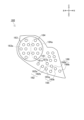
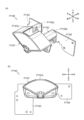
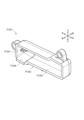
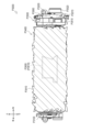
[1-1-3.LEDユニット]
LEDユニット160は、遊技盤ユニット10の右下部であって、遊技領域105の外
側に配置される(図4、図5参照)。LEDユニット160は、各種の表示部を一体化し
たユニット体である。
[1-1-3. LED unit]
The
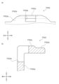
図5は、第1のパチンコ遊技機が備えるLEDユニット160を示す正面図の一例であ
る。
FIG. 5 is an example of a front view showing the
図5に示されるように、LEDユニット160は、普通図柄表示部161、普通図柄用
保留表示部162、第1特別図柄表示部163、第2特別図柄表示部164、第1特別図
柄用保留表示部165、および、第2特別図柄用保留表示部166を備える。
As shown in Figure 5, the
(普通図柄表示部)
普通図柄表示部161は、普通図柄の当り判定処理の結果を表示するものであって、普
通図柄表示LED161a,161bを備える。普通図柄の可変表示を開始するための条
件(以下、「普通図柄の始動条件」と称する)が成立すると、普通図柄表示LED161
a,161bが交互に点灯・消灯を繰り返す普通図柄の可変表示が開始される。普通図柄
の可変表示が開始されてから所定時間が経過すると、普通図柄の可変表示が停止し、普通
図柄の当り判定処理の結果が導出される。
(Normal pattern display section)
The normal
The variable display of the normal symbol is started, in which the
普通図柄の当り判定処理の結果が普通図柄当りである場合、普通図柄表示LED161
a,161bの点灯・消灯の組み合わせが特定の停止表示態様となる。例えば、普通図柄
の当り判定処理の結果が普通図柄当りである場合、普通図柄表示LED161aが点灯す
るとともに普通図柄表示LED161bが消灯する。一方、普通図柄の当り判定処理の結
果がハズレである場合、例えば、普通図柄表示LED161aが消灯するとともに普通図
柄表示LED161bが点灯する。ただし、普通図柄の当り判定処理の結果を示す普通図
柄表示LED161a,161bの停止表示態様はこれに限られない。そして、普通図柄
が特定の停止表示態様で停止表示されると、普通電動役物146を作動させることが決定
し、普電用シャッタ147が所定のパターンで開閉駆動し、第2始動口140Bへの遊技
球の入賞(通過)が容易となる。
When the result of the normal symbol winning judgment process is a normal symbol winning, the normal
A combination of the on/off of the
(普通図柄用保留表示部)
普通図柄用保留表示部162は、普通図柄の可変表示が保留されている場合、保留され
ている普通図柄の可変表示の数(以下、「普通図柄の保留数」と称する)を表示するもの
であって、普通図柄用保留表示LED162a,162bを備える。上記の「普通図柄の
可変表示が保留されている」とは、通過ゲート126への遊技球の通過が検出されて普通
図柄にかかる各種データ(例えば、普通図柄の当り判定用乱数値等)が抽出されてから、
普通図柄の始動条件が成立するまでの状態をいう。なお、普通図柄の始動条件は、普通図
柄が可変表示中でないこと、および、普通図柄の可変表示が保留されていること、を少な
くとも全て満たす場合に成立する。
(Regular pattern reserved display section)
The
This refers to the state until the start condition of the normal pattern is established. The start condition of the normal pattern is established when at least the following is satisfied: the normal pattern is not being displayed in a variable manner, and the variable display of the normal pattern is on hold.
普通図柄用保留表示部162は、普通図柄用保留表示LED162a,162bの点灯
・消灯の組み合わせによって普通図柄の可変表示の保留数を表示する。例えば、普通図柄
の保留数が1個である場合、普通図柄用保留表示LED162aが点灯するとともに普通
図柄用保留表示LED162bが消灯する。また、普通図柄の保留数が2個である場合、
普通図柄用保留表示LED162a,162bの両方が点灯する。また、普通図柄の保留
数が3個である場合、普通図柄用保留表示LED162aが点滅するとともに普通図柄用
保留表示LED162bが点灯する。さらに、普通図柄の保留数が4個である場合、普通
図柄用保留表示LED162a,162bの両方が点滅する。ただし、普通図柄の保留数
を示す普通図柄用保留表示LED162a,162bの表示態様はこれに限られない。
The ordinary symbol reserved
Both of the
(特別図柄表示部)
特別図柄表示部は、特別図柄の当り判定処理の結果を表示するものであって、第1特別
図柄表示部163および第2特別図柄表示部164を備える。第1特別図柄表示部163
は、例えば8個のLEDからなる第1特別図柄表示LED群163aを備える。同様に、
第2特別図柄表示部164も、例えば8個のLEDからなる第2特別図柄表示LED群1
64aを備える。
(Special design display section)
The special symbol display unit displays the result of the special symbol winning determination process, and includes a first special
is provided with a first special symbol
The second special
64a.
第1特別図柄の可変表示を開始するための条件(以下、「第1特別図柄の始動条件」と
称する)が成立すると、第1特別図柄表示LED群163aが交互または相互に点灯・消
灯を繰り返す第1特別図柄の可変表示が開始される。第1特別図柄の可変表示が開始され
てから所定時間が経過すると、第1特別図柄の可変表示が停止し、第1特別図柄の当り判
定処理の結果が導出される。
When the condition for starting the variable display of the first special symbol (hereinafter referred to as the "start condition of the first special symbol") is satisfied, the variable display of the first special symbol is started in which the first special symbol
第1特別図柄の当り判定処理の結果が大当りである場合、第1特別図柄表示部163を
構成する第1特別図柄表示LED群163a(例えば8個のLED)の点灯・消灯の組み
合わせが特定の停止表示態様となる。そして、第1特別図柄表示部163が特定の停止表
示態様で停止表示されると、大当り遊技状態への移行が決定する。
When the result of the hit determination process of the first special symbol is a jackpot, a combination of on/off of the first special symbol
第2特別図柄の可変表示を開始するための条件(以下、「第2特別図柄の始動条件」と
称する)が成立すると、第2特別図柄表示LED群164aが交互または相互に点灯・消
灯を繰り返す第2特別図柄の可変表示が開始される。第2特別図柄の可変表示が開始され
てから所定時間が経過すると、第2特別図柄の可変表示が停止し、第2特別図柄の当り判
定処理の結果が導出される。
When the condition for starting the variable display of the second special symbol (hereinafter referred to as the "start condition of the second special symbol") is satisfied, the variable display of the second special symbol is started in which the second special symbol
第2特別図柄の当り判定処理の結果が大当りである場合、第2特別図柄表示部164を
構成する第2特別図柄表示LED群164a(例えば8個のLED)の点灯・消灯の組み
合わせが特定の停止表示態様となる。そして、第2特別図柄表示部164が特定の停止表
示態様で停止表示されると、大当り遊技状態への移行が決定する。
When the result of the hit determination process of the second special symbol is a jackpot, a combination of on/off of the second special symbol
(特別図柄用保留表示部)
特別図柄用保留表示部は、特別図柄の可変表示が保留されている場合、保留されている
特別図柄の可変表示の数(以下、「特別図柄の保留数」と称する)を表示するものであっ
て、第1特別図柄用保留表示部165および第2特別図柄用保留表示部166を備える。
(Special design reserved display section)
The special pattern reserve display unit displays the number of reserved variable displays of special patterns (hereinafter referred to as the "reserved number of special patterns") when variable displays of special patterns are reserved, and is provided with a first special pattern
第1特別図柄用保留表示部165は、第1特別図柄の可変表示が保留されている場合、
第1特別図柄の保留数を表示するものであって、第1特別図柄用保留表示LED165a
,165bを備える。「第1特別図柄の可変表示が保留されている」とは、第1始動口1
20への遊技球の入賞(通過)が検出されて第1特別図柄にかかる各種データ(例えば、
第1特別図柄の大当り判定用乱数値、第1特別図柄の図柄乱数値、第1特別図柄のリーチ
判定用乱数値、および、第1特別図柄の変動パターンの決定時に用いられる演出選択用乱
数値等の各種乱数値等)が抽出されてから、第1特別図柄の始動条件が成立するまでの状
態をいう。なお、第1特別図柄の始動条件については後述する。
When the variable display of the first special symbol is reserved, the first special symbol reserved
The number of reserved first special symbols is displayed. The
, 165b. "The variable display of the first special symbol is reserved" means that the
When the entry (passage) of the game ball into 20 is detected, various data related to the first special symbol (for example,
The state from when the random numbers for determining the jackpot of the first special symbol, the random number for the symbol of the first special symbol, the random number for determining the reach of the first special symbol, and the random number for selecting the performance used when determining the variation pattern of the first special symbol are extracted to when the start condition of the first special symbol is established. The start condition of the first special symbol will be described later.
第1特別図柄用保留表示部165は、第1特別図柄用保留表示LED165a,165
bの点灯・消灯の組み合わせによって第1特別図柄の可変表示の保留数を表示する。例え
ば、第1特別図柄の保留数が1個である場合、第1特別図柄用保留表示LED165aが
点灯するとともに第1特別図柄用保留表示LED165bが消灯する。また、第1特別図
柄の保留数が2個である場合、第1特別図柄用保留表示LED165a,165bの両方
が点灯する。また、第1特別図柄の保留数が3個である場合、第1特別図柄用保留表示L
ED165aが点滅するとともに第1特別図柄用保留表示LED165bが点灯する。さ
らに、第1特別図柄の保留数が4個である場合、第1特別図柄用保留表示LED165a
,165bの両方が点滅する。ただし、第1特別図柄の保留数を示す第1特別図柄用保留
表示LED165a,165bの表示態様はこれに限られない。
The first special symbol reserved
The number of reserved first special symbols is displayed by a combination of the lighting and extinguishing of the first special symbol reserved
The
However, the display mode of the first special symbol reserved
第2特別図柄用保留表示部166は、第2特別図柄の可変表示が保留されている場合、
第2特別図柄の保留数を表示するものであって、第2特別図柄用保留表示LED166a
,166bを備える。「第2特別図柄の可変表示が保留されている」とは、第2始動口1
40A,140Bへの遊技球の入賞(通過)が検出されて第2特別図柄にかかる各種デー
タ(例えば、第2特別図柄の大当り判定用乱数値、第2特別図柄の図柄乱数値、第2特別
図柄のリーチ判定用乱数値、および、第2特別図柄の変動パターンの決定時に用いられる
演出選択用乱数値等の各種乱数値等)が抽出されてから、第2特別図柄の始動条件が成立
するまでの状態をいう。なお、第2特別図柄の始動条件については後述する。
The second special symbol reserved
The number of reserved second special symbols is displayed. The
, 166b. "The variable display of the second special symbol is reserved" means that the
It refers to the state from when the entrance (passage) of the game ball into 40A, 140B is detected and various data related to the second special symbol (for example, various random numbers such as a random number value for determining a jackpot for the second special symbol, a random number value for the symbol of the second special symbol, a random number value for determining a reach for the second special symbol, and a random number value for selecting an effect used when determining the variation pattern of the second special symbol) is extracted until the start condition of the second special symbol is established. The start condition of the second special symbol will be described later.
第2特別図柄用保留表示部166は、第2特別図柄用保留表示LED166a,166
bの点灯・消灯の組み合わせによって第2特別図柄の可変表示の保留数を表示する。例え
ば、第2特別図柄の保留数が1個である場合、第2特別図柄用保留表示LED166aが
点灯するとともに第2特別図柄用保留表示LED166bが消灯する。また、第2特別図
柄の保留数が2個である場合、第2特別図柄用保留表示LED166a,166bの両方
が点灯する。また、第2特別図柄の保留数が3個である場合、第2特別図柄用保留表示L
ED166aが点滅するとともに第2特別図柄用保留表示LED166bが点灯する。さ
らに、第2特別図柄の保留数が4個である場合、第2特別図柄用保留表示LED166a
,166bの両方が点滅する。ただし、第2特別図柄の保留数を示す第2特別図柄用保留
表示LED166a,166bの表示態様はこれに限られない。
The second special symbol reserved
The number of reserved second special symbols is displayed by a combination of lighting and extinguishing
The
However, the display mode of the second special symbol reserved
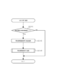
[1-2.電気的構成]
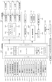
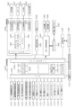
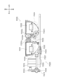
次に、図6を参照して、第1のパチンコ遊技機の制御回路について説明する。図6は、
第1のパチンコ遊技機の制御回路を示すブロック図の一例である。
[1-2. Electrical configuration]
Next, the control circuit of the first pachinko gaming machine will be described with reference to FIG.
2 is an example of a block diagram showing a control circuit of the first pachinko gaming machine;
図6に示されるように、第1のパチンコ遊技機は、主に、遊技の制御を行う主制御回路
200と、遊技の進行に応じた演出の制御を行うサブ制御回路300と、払出・発射制御
回路400と、電源供給回路450と、から構成される。
As shown in FIG. 6, the first pachinko game machine is mainly composed of a
[1-2-1.主制御回路]
主制御回路200は、例えば電源投入時に実行される処理や遊技動作にかかわる処理等
を制御するものであって、メインCPU201、メインROM202(読み出し専用メモ
リ)、メインRAM203(読み書き可能メモリ)、初期リセット回路204およびバッ
クアップコンデンサ207等を備えており、主基板ケース(不図示)内に収容されている
。
[1-2-1. Main control circuit]
The
メインCPU201には、メインROM202、メインRAM203および初期リセッ
ト回路204等が接続される。メインCPU201は、動作を監視するWDT(watchdog
timer)や不正を防止するための機能等が内蔵されている。
A
It also has built-in functions such as a password timer and fraud prevention features.
メインROM202には、メインCPU201により第1のパチンコ遊技機の動作を制
御するためのプログラムや、各種のテーブル等が記憶されている。メインCPU201は
、メインROM202に記憶されたプログラムに従って、各種の処理を実行する機能を有
する。
The
メインRAM203には、遊技の進行に必要な各種データを記憶する記憶領域が設けら
れている。このメインRAM203は、メインCPU201の一時記憶領域として、種々
のフラグや変数の値を記憶する機能を有する。なお、本実施例においては、メインCPU
201の一時記憶領域としてRAMを用いているが、これに限らず、読み書き可能な記憶
媒体であればよい。
The
Although a RAM is used as the
初期リセット回路204は、メインCPU201を監視し、必要に応じてリセット信号
を出力するものである。
The
バックアップコンデンサ207は、電断時等に、メインRAM203に格納されている
データが消失しないように一時的に電力を供給する機能を有するものである。
The
さらに、主制御回路200は、各種デバイス等との間で通信可能に接続されるI/Oポ
ート205、および、サブ制御回路300に対して各種コマンドを出力可能に接続される
コマンド出力ポート206等も備える。
Furthermore, the
また、主制御回路200には、各種のデバイスが接続されている。例えば、主制御回路
200には、上述した普通図柄表示部161、普通図柄用保留表示部162、第1特別図
柄表示部163、第2特別図柄表示部164、第1特別図柄用保留表示部165、第2特
別図柄用保留表示部166、普電用ソレノイド148、特電用ソレノイド135、および
、小当り用ソレノイド154等が接続されている。また、主制御回路200には、これら
の他、性能表示モニタ170およびエラー報知モニタ172等も接続されている。主制御
回路200は、I/Oポート205を介して信号を送信することにより、これらのデバイ
スの動作を制御することができる。
In addition, various devices are connected to the
性能表示モニタ170には、メインCPU201の制御により性能表示データや後述す
る設定値等が表示される。性能表示データは、例えば、所定数(例えば60000個)の
遊技球の発射に対して大当り遊技状態以外の遊技状態で払い出された遊技球の割合を示す
データであり、ベース値とも呼ばれる。
The performance display monitor 170 displays performance display data and setting values (described later) under the control of the
エラー報知モニタ172には、エラーコードが表示される。また、エラー報知モニタ1
72には、エラーコードの他に、例えば後述する設定機能付きのパチンコ遊技機であれば
、設定変更処理中であることを示す設定変更中コード、設定確認処理中であることを示す
設定確認中コード等を表示することもできる。なお、設定変更中コードとしては、特別図
柄表示装置において通常では表示することのない図柄(例えば、設定変更中であることを
示す設定変更図柄)を表示するようにしてもよい。
The error notification monitor 172 displays an error code.
In addition to the error code, for example, in the case of a pachinko game machine with a setting function described later, a setting change code indicating that a setting change process is in progress, a setting confirmation code indicating that a setting confirmation process is in progress, etc. can be displayed on 72. Note that, as the setting change code, a symbol that is not normally displayed on the special symbol display device (for example, a setting change symbol indicating that a setting change is in progress) may be displayed.
また、主制御回路200には、第1始動口スイッチ121、第2始動口スイッチ141
A,141B、通過ゲートスイッチ127、大当り用大入賞口カウントスイッチ132、
一般入賞口スイッチ123および小当り用大入賞口カウントスイッチ152等も接続され
ている。これらのスイッチが検出されると、検出信号がI/Oポート205を介して主制
御回路200に出力される。
In addition, the
A, 141B, a
Also connected are the general winning
さらに、主制御回路200には、ホール係員を呼び出す機能や大当り回数を表示する機
能等を有する呼出装置(不図示)、ホール全体のパチンコ遊技機を管理するホールコンピ
ュータ186にデータ送信する際に用いる外部端子板184、後述する設定機能付きのパ
チンコ遊技機であれば設定値を変更したり確認したりする際に操作される設定キー174
、メインRAM203に格納されるバックアップデータを遊技場の管理者の操作に応じて
クリアすることが可能なバックアップクリアスイッチ176等が接続されている。本実施
例において、バックアップクリアスイッチ176は、後述する設定値を変更する際のスイ
ッチも兼用しているが、これに限られず、設定値を変更するための設定スイッチを設ける
ようにしてもよい。
Furthermore, the
A backup clear switch 176 is connected to the
また、設定キー174およびバックアップクリアスイッチ176は、遊技場の管理者以
外の第三者(例えば遊技者)が容易に触ることができないように、所定のケース内に収容
されていることが好ましい。「所定のケース内」には、当該ケースを開放しないと設定キ
ー174やバックアップクリアスイッチ176に接触できない構成のものだけでなく、当
該ケースの設定キー174およびバックアップクリアスイッチ176の対応箇所にのみ切
欠きが設けられ、遊技場の管理者が管理する鍵を使用して島設備からパチンコ遊技機を回
動させて背面を露出させたときに、遊技場の管理者が設定キー174または/およびバッ
クアップクリアスイッチ176に接触できるように構成されているものも含まれる。
Moreover, the setting
なお、本実施例では、設定キー174およびバックアップクリアスイッチ176は、主
制御回路200に接続されているが、これに限られず、例えば、払出・発射制御回路40
0や電源供給回路450に接続されるような構成にしてもよい。この場合にもまた、遊技
場の管理者以外の第三者が設定キー174やバックアップクリアスイッチ176に容易に
接触できないようにすることが好ましい。
In this embodiment, the setting
0 or the
[1-2-2.サブ制御回路]
サブ制御回路300は、サブCPU301、プログラムROM302、ワークRAM3
03、表示制御回路304、音声制御回路305、LED制御回路306、役物制御回路
307およびコマンド入力ポート308等を備える。サブ制御回路300は、主制御回路
200からの指令に応じて遊技の進行に応じた演出を実行する。なお、図6には示されて
いないが、サブ制御回路300には、遊技者が操作可能な演出ボタン54(図1参照)等
も接続されている。
[1-2-2. Sub-control circuit]
The
6, the
プログラムROM302には、サブCPU301により第1のパチンコ遊技機の遊技演
出を制御するためのプログラムや、各種のテーブル等が記憶されている。サブCPU30
1は、プログラムROM302に記憶されたプログラムに従って、各種の処理を実行する
機能を有する。特に、サブCPU301は、主制御回路200から送信される各種のコマ
ンドに従って、遊技演出にかかる制御を行う。
The
The
ワークRAM303は、サブCPU301の一時記憶領域として種々のフラグや変数の
値を記憶する機能を有する。
The
表示制御回路304は、表示装置7における表示制御を行うための回路である。表示制
御回路304は、画像データプロセッサ(以下、VDPと称する)や、各種の画像データ
を生成するためのデータが記憶されている画像データROM、画像データを一時的に格納
するフレームバッファ、画像データを画像信号として変換するD/Aコンバータ等を備え
る。
The
表示制御回路304は、サブCPU301からの画像表示命令に応じて、表示装置7に
表示させるための画像データを一時的にフレームバッファに格納する。なお、表示装置7
に表示させるための画像データには、装飾図柄を示す装飾図柄画像データ、背景画像デー
タ、演出用画像データ等の、遊技に関する各種の画像データが含まれる。
The
The image data to be displayed includes various image data related to the game, such as decorative pattern image data showing decorative patterns, background image data, and image data for effects.
そして、表示制御回路304は、所定のタイミングで、フレームバッファに格納された
画像データをD/Aコンバータに供給する。D/Aコンバータは、画像データを画像信号
として変換し、当該変換した画像信号を所定のタイミングで表示装置7に供給する。表示
装置7に画像信号が供給されると、表示装置7に当該画像信号に関する画像が表示される
。こうして、表示制御回路304は、表示装置7に遊技に関する画像を表示させる制御を
行うことができる。
Then, the
音声制御回路305は、スピーカ32から発生させる音声に関する制御を行うための回
路である。音声制御回路305は、音声に関する制御を行う音源ICや、各種の音声デー
タを記憶する音声データROM、音声信号を増幅するための増幅器(以下、AMPと称す
る)等を備える。
The
音源ICは、スピーカ32から出力される音声の制御を行う。音源ICは、サブCPU
301からの音声発生命令に応じて、音声データROMに記憶されている複数の音声デー
タから一つの音声データを選択する。また、音源ICは、選択された音声データを音声デ
ータROMから読み出し、音声データを所定の音声信号に変換し、当該変換した音声信号
をAMPに供給する。AMPは、スピーカ32から出力される音声や効果音等の信号を増
幅させるものである。
The sound source IC controls the sound output from the
In response to a voice generation command from the
LED制御回路306は、装飾LED等を含むLED群46の制御を行うための回路で
ある。LED制御回路306は、LED制御信号を供給するためのドライブ回路や、複数
種類のLED装飾パターンが記憶されている装飾データROM等を備える。
The
役物制御回路307は、各役物(例えば、演出用役物群58のうちの一または複数の役
物)の動作を制御するための回路である。役物制御回路307は、各役物に対して、駆動
信号を供給するための駆動回路や動作パターンが記憶されている役物データROM等を備
える。
The
また、役物制御回路307は、サブCPU301からの役物作動命令に応じて、役物デ
ータROMに記憶されている複数の動作パターンから一つの動作パターンを選択する。そ
して、選択した動作パターンを役物データROMから読み出し、読み出した動作パターン
に対応する駆動信号を供給することにより、各役物の機械的な動作を制御する。また、点
灯回路は、サブCPU301からの点灯命令に基づいて、役物データROMに記憶されて
いる複数の点灯パターンから一つの点灯パターンを選択する。そして、選択した点灯パタ
ーンを役物データROMから読み出し、読み出した点灯パターンに対応する点灯制御信号
を供給することにより、各役物の点灯動作を制御する。
In addition, the
コマンド入力ポート308は、コマンド出力ポート206と接続されており、主制御回
路200から送信された各種コマンドを受信するものである。
The
払出・発射制御回路400は、賞球や貸球の払い出しを制御するものであり、この払出
・発射制御回路400には、遊技球を払い出すことが可能な払出装置82、遊技球を発射
させることが可能な発射装置6、球貸しにかかる制御を実行可能なカードユニット180
等が接続されている。
The payout/
etc. are connected.
払出・発射制御回路400は、主制御回路200から送信される賞球制御コマンドを受
信すると、払出装置82に対して所定の信号を送信し、払出装置82に遊技球を払い出さ
せる制御を行う。
When the payout/
カードユニット180には、球貸し操作パネル182が接続されている。球貸し操作パ
ネル182には、球貸しを受けるための球貸しボタンや、キャッシュデータが記憶されて
いる球貸しカードの返却を受けるための貸出返却ボタン(いずれも不図示)が設けられて
いる。例えば遊技者によって球貸し操作が行われると、球貸し操作に応じた貸し球制御信
号がカードユニット180に送信される。払出・発射制御回路400は、カードユニット
180から送信された貸し球制御信号に基づいて、払出装置82に遊技球を払い出させる
制御を行う。なお、操作パネル182は、パチンコ遊技機側に設けられることが多いが、
カードユニット180側に設けられてもよい。
A ball
It may be provided on the
また、払出・発射制御回路400は、発射ハンドル62が時計回りの方向へ回動操作さ
れたことに基づいて、その回動角度(回動量)に応じて発射ソレノイド(図示せず)に電
力を供給し、遊技球を発射させる制御を行う。
In addition, when the launch handle 62 is rotated clockwise, the payout/
電源供給回路450は、遊技に際して必要な電源電圧を、主制御回路200、サブ制御
回路300、払出・発射制御回路400等に供給するために作成する電源回路である。
The
電源供給回路450には、電源スイッチ95等が接続されている。電源スイッチ95は
、パチンコ遊技機(より詳しくは、主制御回路200、サブ制御回路300、払出・発射
制御回路400等)に必要な電源を供給するときにオン操作するものである。
A
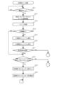
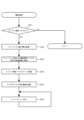
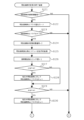
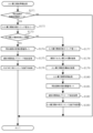
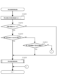
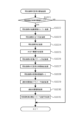
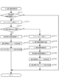
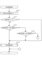
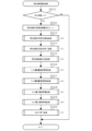
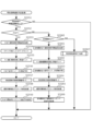
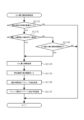
[1-3.遊技フロー]
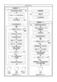
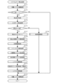
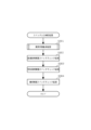
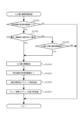
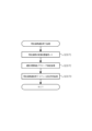
次に、図7を参照して、第1のパチンコ遊技機の遊技フローについて説明する。図7は
、第1のパチンコ遊技機の遊技フローの一例である。なお、図7に示される遊技フローは
、制御上のフローではなく、外観で把握できるフローである。
[1-3. Game flow]
Next, the game flow of the first pachinko game machine will be described with reference to Fig. 7. Fig. 7 is an example of the game flow of the first pachinko game machine. Note that the game flow shown in Fig. 7 is not a control flow but a flow that can be grasped from the outside.
図7に示されるように、パチンコゲームでは、遊技者等のユーザー操作により遊技球が
発射され、その遊技球が各種入賞口(例えば、第1始動口120等)に入賞した場合に遊
技球の払出制御処理が行われる。パチンコゲームには、特別図柄を用いる特別図柄ゲーム
と、普通図柄を用いる普通図柄ゲームとが含まれる。特別図柄ゲームとは、例えば、始動
口120,140A,140Bへの遊技球の入賞に基づいて特別図柄の当り判定処理を実
行し、大当り遊技状態に移行させるか否か等を決定するゲームである。また、普通図柄ゲ
ームとは、例えば、通過ゲート126への遊技球の通過に基づいて普通図柄の当り判定処
理を実行し、普通電動役物146を作動させて入賞口(本実施例では第2始動口140B
)を開放状態とするか否か等を決定するゲームである。なお、この明細書において、「特
別図柄ゲーム」を「遊技」と称する場合もあるが、「遊技」は広い概念で用いられる用語
であり、例えば、普通図柄ゲームや演出ボタン54等の操作部(例えば図1参照)を使用
する演出上のゲーム等も「遊技」に含まれる。
As shown in FIG. 7, in a pachinko game, a game ball is launched by a user operation such as a player, and when the game ball enters one of the various winning ports (for example, the
In this specification, the "special symbol game" may be referred to as a "game", but the term "game" is used in a broad sense, and for example, normal symbol games and games using an operation unit such as the effect button 54 (see FIG. 1) are also included in the "game".
また、この明細書において、特別図柄の可変表示が開始されてから、この可変表示が終
了して特別図柄の当り判定処理の結果が確定表示(導出)されるまで(より詳しくは、特
別図柄確定時間が経過するまで)を1回の特別図柄ゲームとする。ただし、特別図柄の当
り判定処理の結果が導出された後、大当り遊技状態や小当り遊技状態に制御された場合は
、大当り遊技状態や小当り遊技状態の終了までを1回の特別図柄ゲームとする。
In this specification, one special symbol game is defined as the period from when the variable display of the special symbol starts until the variable display ends and the result of the special symbol hit determination process is displayed (derived) (more specifically, until the special symbol determination time has elapsed). However, if the game is controlled to a big hit game state or a small hit game state after the result of the special symbol hit determination process is derived, one special symbol game is defined as the period until the big hit game state or the small hit game state ends.
特別図柄ゲームにおいて大当りを示す停止表示態様が第1特別図柄表示部163または
第2特別図柄表示部164に導出されると、大当り遊技状態に制御される。大当り遊技状
態では、特別電動役物133の作動によって大当り用大入賞口131が所定時間(例えば
最大30000msec)にわたって開放状態となるラウンド遊技が実行され、大当り用
大入賞口131への入賞可能性が相対的に高められる。
When a stop display mode indicating a jackpot in the special symbol game is derived to the first special
また、普通図柄ゲームにおいて普通図柄当りを示す停止表示態様が普通図柄表示部16
1に導出されると、普通電動役物146の作動によって入賞口(例えば、本実施例では第
2始動口140B)が開放状態となり、例えば第2始動口140Bへの入賞可能性が相対
的に高められる。
In addition, in the normal symbol game, the stop display mode indicating the normal symbol win is set to the normal symbol display unit 16.
When the ball is led out to 1, the winning hole (for example, the
なお、パチンコゲームにおいて実行可能なゲームは、特別図柄ゲームおよび普通図柄ゲ
ームに限られず、これらとは別の新たなゲームを実行可能であってもよい。
It should be noted that games that can be executed in a pachinko game are not limited to special symbol games and normal symbol games, and new games different from these may also be executable.
以下、特別図柄ゲームおよび普通図柄ゲームの遊技フローの概要を説明する。 The following provides an overview of the game flow for special symbol games and regular symbol games.
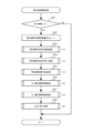
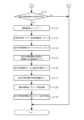
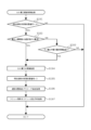
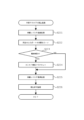
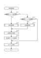
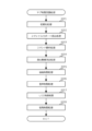
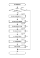
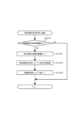
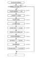
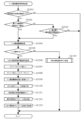
[1-3-1.特別図柄ゲーム]
図7に示されるように、特別図柄ゲームには、主として、第1始動口120または第2
始動口140A,140Bへの入賞(通過)があった場合に行われる特別図柄始動入賞処
理、および、特別図柄の始動条件が成立したことに基づいて行われる特別図柄制御処理、
等が含まれる。
[1-3-1. Special symbol game]
As shown in FIG. 7, the special symbol game mainly includes a
A special symbol start winning process which is carried out when a winning (passing) occurs in the start opening 140A, 140B, and a special symbol control process which is carried out based on the establishment of the start condition of the special symbol;
etc. are included.
第1始動口120または第2始動口140A,140Bへの遊技球の入賞があった場合
、特別図柄始動入賞処理が行われる。この特別図柄始動入賞処理では、特別図柄用の各種
カウンタ(例えば、大当り判定用カウンタ、図柄決定用カウンタ等)から特別図柄にかか
る各種データ(例えば、大当り判定用乱数値、図柄乱数値、リーチ判定用乱数値、および
、演出選択用乱数値等の各種乱数値等)がそれぞれ抽出(取得)される。抽出された各乱
数値は始動情報として保留される。この特別図柄始動入賞処理は、特別図柄制御処理の実
行中であっても行われる。
When a game ball enters the
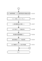
また、特別図柄制御処理では、特別図柄の始動条件が成立したか否かが判定される。特
別図柄の始動条件が成立すると、特別図柄の大当り判定用カウンタから抽出された大当り
判定用乱数値を参照し、「大当り」であるか否かを判定する特別図柄の当り判定処理が行
われる。その後、停止図柄を決定する停止図柄決定処理が行われる。停止図柄決定処理で
は、特別図柄の図柄決定用カウンタから抽出された図柄決定用乱数値と、特別図柄の当り
判定処理の結果とを参照し、停止表示させる特別図柄が決定される。
In addition, in the special symbol control process, it is determined whether or not the start condition of the special symbol is satisfied. When the start condition of the special symbol is satisfied, a special symbol hit determination process is performed to determine whether or not there is a "big hit" by referring to a random number value for determining a big hit extracted from a counter for determining a big hit of the special symbol. After that, a stop symbol determination process is performed to determine a stop symbol. In the stop symbol determination process, the special symbol to be stopped is determined by referring to the random number value for determining a symbol extracted from the counter for determining a symbol of the special symbol and the result of the hit determination process of the special symbol.
なお、本実施例では、確変フラグがオンであれば確変制御が実行される。上記の特別図
柄の当り判定処理では、確変フラグがオフの場合は相対的に低い確率で「大当り」である
と判定され、確変フラグがオンの場合は相対的に高い確率で「大当り」であると判定され
る。以下、この明細書において、「大当り」であると判定される確率を「大当り確率」と
称する。
In this embodiment, if the probability variable flag is on, the probability variable control is executed. In the above-mentioned special symbol winning judgment process, if the probability variable flag is off, it is judged to be a "jackpot" with a relatively low probability, and if the probability variable flag is on, it is judged to be a "jackpot" with a relatively high probability. Hereinafter, in this specification, the probability of being judged to be a "jackpot" is referred to as the "jackpot probability."
なお、確変フラグは、メインRAM203に格納される管理フラグの一つであり、確変
制御を実行するか否かを管理するためのフラグである。確変フラグがオンの場合、確変制
御が実行される遊技状態(例えば、本実施例では高確時短遊技状態や高確非時短遊技状態
)において遊技が進行する。一方、確変フラグがオフの場合、確変制御が実行されない遊
技状態(例えば、通常遊技状態や低確時短遊技状態)において遊技が進行する。
The probability variable flag is one of the management flags stored in the
次いで、特別図柄の変動パターン決定処理が行われる。この処理では、変動パターン決
定用カウンタから乱数値を抽出し、その乱数値と、上述した特別図柄の当り判定処理の結
果と、上述した停止表示させる特別図柄とを参照し、特別図柄の変動パターン(可変表示
パターン)が決定される。そして、特別図柄の変動パターン決定処理の結果に基づいて特
別図柄の可変表示制御処理が行われる。
Next, a process for determining the variation pattern of the special symbols is performed. In this process, a random number is extracted from the variation pattern determination counter, and the variation pattern (variable display pattern) of the special symbols is determined by referring to the random number, the result of the above-mentioned special symbol winning judgment process, and the above-mentioned special symbols to be stopped and displayed. Then, a process for controlling the variable display of the special symbols is performed based on the result of the variation pattern determination process of the special symbols.
特別図柄の変動パターンが決定されると、次に演出パターンを決定するための演出パタ
ーン決定処理が行われる。そして、演出パターン決定処理の結果に基づいて、表示装置7
の表示領域に表示される例えば装飾図柄やキャラクタ演出等の表示演出、および、スピー
カ32から出力される音声や効果音等の音演出等の演出制御処理が行われる。なお、演出
制御処理はサブCPU301によって行われる。
When the variation pattern of the special symbol is determined, a performance pattern determination process is then performed to determine the performance pattern. Then, based on the result of the performance pattern determination process, the
The sub-CPU 301 controls the display of the display area, such as decorative patterns and character effects, and the sound effects, such as voice and sound effects, output from the
そして、特別図柄の可変表示制御処理および演出制御処理が終了し、大当りである場合
、大当り遊技制御処理が行われる。大当り遊技制御処理は、大当り遊技状態において実行
される処理である。大当り遊技状態が終了すると、特別図柄ゲームが終了し、大当りでな
い遊技状態への遊技状態移行制御処理が行われる。この場合、大当りの種類に応じて遊技
状態が移行する。例えば、確変フラグおよび時短フラグのいずれもがオンにセットされる
大当り種類である場合、大当り遊技状態の終了後、確変時短遊技状態に移行する。
Then, when the special symbol variable display control process and the presentation control process are completed and it is a jackpot, a jackpot game control process is performed. The jackpot game control process is a process executed in the jackpot game state. When the jackpot game state ends, the special symbol game ends, and a game state transition control process to a game state that is not a jackpot is performed. In this case, the game state transitions according to the type of jackpot. For example, when the jackpot type is one in which both the probability variable flag and the time-saving flag are set to on, the game state transitions to the probability variable time-saving game state after the jackpot game state ends.
一方、大当りでないすなわちハズレである場合、特別図柄ゲームが終了する。なお、図
7には示されていないが、小当りである場合、小当り遊技制御処理が行われる。
On the other hand, if the winning combination is not a big win, i.e., a miss, the special symbol game ends. Although not shown in FIG. 7, if the winning combination is a small win, a small win game control process is performed.
そして、特別図柄の始動条件が成立する都度、上述した特別図柄制御処理の各種処理が
繰り返される。
Then, each time the starting condition for the special symbol is satisfied, various processes of the special symbol control process described above are repeated.
なお、特別図柄制御処理中に始動口120,140A,140Bへの遊技球の入賞があ
った場合、特別図柄始動入賞処理が実行される。また、始動口120,140A,140
Bへの遊技球の入賞時に抽出される特別図柄の始動情報(例えば、大当り判定用乱数値、
特別図柄の図柄乱数値、リーチ判定用乱数値、および、演出選択用乱数値等の各種乱数値
等の各種データ)を、特別図柄の始動条件が成立するまで保留する。
In addition, if a game ball enters the
The starting information of the special pattern extracted when the game ball enters B (for example, the random number value for determining the big win,
Various data such as random number values for the special pattern, random number values for reach determination, and random number values for performance selection are held until the conditions for starting the special pattern are met.
また、第1のパチンコ遊技機では、第1特別図柄の始動情報の4個と第2特別図柄の始
動情報の4個とで合計最大8個まで特別図柄の始動情報を保留することができるが、保留
できる特別図柄の始動情報の数はこれに限られない。例えば、第1特別図柄の始動情報を
第2特別図柄の始動情報よりも多く保留できるようにしてもよいし、第2特別図柄の始動
情報を第1特別図柄の始動情報よりも多く保留できるようにしてもよい。
In addition, in the first pachinko game machine, the start information of the special symbols can be reserved up to a maximum of eight in total, consisting of four pieces of start information of the first special symbol and four pieces of start information of the second special symbol, but the number of start information of the special symbols that can be reserved is not limited to this. For example, the start information of the first special symbol may be reserved more than the start information of the second special symbol, or the start information of the second special symbol may be reserved more than the start information of the first special symbol.
また、図7には示されていないが、特別図柄が始動入賞してから特別図柄の始動条件が
成立するまでの間に、始動口120,140A,140Bへの遊技球の入賞(通過)時に
抽出された始動情報に基づいて当落(「大当り」当選の有無)や変動パターンを特別図柄
の当り判定処理に先だって判定する先読み判定を行い、この先読み判定の結果に基づいて
所定の演出を行う先読み演出機能を備えるようにしてもよい。なお、上記の先読み判定は
、始動口120,140A,140Bへの遊技球の入賞によって抽出された始動情報が保
留される前に行ってもよいし、保留された後に行ってもよい。
7, a pre-reading function may be provided that performs a pre-reading judgment to judge whether or not a special symbol will win (whether or not a "jackpot" will be won) and a variation pattern prior to the hit judgment process of the special symbol based on the start information extracted when the game ball enters (passes) the start holes 120, 140A, and 140B between the start entry of the special symbol and the establishment of the start condition of the special symbol, and performs a predetermined performance based on the result of this pre-reading judgment. Note that the above-mentioned pre-reading judgment may be performed before or after the start information extracted by the entry of the game ball into the start holes 120, 140A, and 140B is reserved.
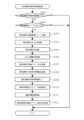
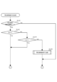
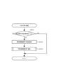
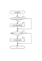
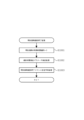
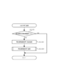
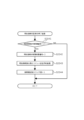
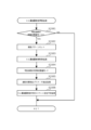
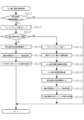
[1-3-2.普通図柄ゲーム]
図7に示されるように、普通図柄ゲームには、主として、通過ゲート126への遊技球
の通過があった場合に行われる普通図柄始動通過処理、および、普通図柄の始動条件が成
立したことに基づいて行われる普通図柄制御処理、等が含まれる。
[1-3-2. Normal symbol game]
As shown in FIG. 7, the normal pattern game mainly includes a normal pattern start passing process which is carried out when the game ball passes through the passing
通過ゲート126への遊技球の通過があった場合、普通図柄始動通過処理が実行される
。この普通図柄始動通過処理では、普通図柄用の当り判定用カウンタから普通図柄の始動
情報(例えば、普通図柄の当り判定用乱数値等)を抽出(取得)し、抽出した始動情報を
保留する。
When the game ball passes through the passing
また、普通図柄制御処理では、メインCPU201は、普通図柄の始動条件が成立した
か否かを判定する。普通図柄の可変表示を開始する場合、メインCPU201は、普通図
柄用の当り判定用カウンタから抽出された普通図柄の当り判定用乱数値を参照し、「普通
図柄当り」とするか否かの普通図柄の当り判定処理を実行し、その後、変動パターン決定
処理を実行する。この処理では、普通図柄の当り判定処理の結果が参照され、普通図柄の
変動パターンが決定される。
In addition, in the normal symbol control process, the
次いで、メインCPU201は、普通図柄当り判定処理の結果、および、決定された普
通図柄の変動パターンを参照し、普通図柄の可変表示の制御を行う可変表示制御処理、お
よび、所定の演出を行う演出制御処理を実行する。なお、演出制御処理は実行されない場
合もある。
Next, the
そして、普通図柄の可変表示制御処理および演出制御処理が終了すると、メインCPU
201は、「普通図柄当り」を示す普通当り図柄が普通図柄表示部161(図6参照)に
導出されたか否かを判定する。普通当りを示す停止表示態様が導出されたと判定すると、
メインCPU201は、普通図柄当り遊技制御処理を実行する。この普通図柄当り遊技制
御処理では、普通電動役物146(図4、図6参照)が作動し、入賞口(例えば、本実施
例では例えば第2始動口140B(図4参照))への遊技球の入賞(通過)が可能または
容易な開放状態となる。一方、普通当りを示す停止表示態様が導出されなかったと判定す
ると、メインCPU201は、普通図柄当り遊技制御処理を実行せず、普通図柄制御処理
を終了する。
Then, when the variable display control process and the performance control process of the normal pattern are completed, the main CPU
201 judges whether or not a normal winning pattern indicating a "normal winning pattern" has been output to the normal pattern display unit 161 (see FIG. 6). When it is judged that a stop display mode indicating a normal winning pattern has been output,
The
なお、時短制御が実行されない遊技状態(例えば、通常遊技状態)では、普通当りを示
す停止表示態様が導出される確率を0にしてもよい。時短制御は、時短制御が実行されて
いないときと比べて、特別図柄の可変表示時間を短縮させる特図短縮制御、および、普通
電動役物146を作動させて入賞口(本実施例では例えば第2始動口140B)を開放状
態とする頻度を高める電サポ制御、のうち少なくともいずれか一方が行われる制御が相当
する。この時短制御は、特図短縮制御および電サポ制御の両方を行う制御としてもよいし
、特図短縮制御および電サポ制御のうちいずれか一方のみを行う制御としてもよい。
In addition, in a game state where the time-saving control is not executed (for example, a normal game state), the probability of deriving a stop display mode indicating a normal win may be set to 0. The time-saving control corresponds to at least one of the following: a special symbol shortening control that shortens the variable display time of the special symbol, and an electric support control that increases the frequency of opening the winning hole (for example, the
そして、普通図柄の始動条件が成立する都度、上述した普通図柄制御処理の各種処理が
繰り返される。
Then, each time the starting condition for the normal symbol is satisfied, various processes of the normal symbol control process described above are repeated.
なお、普通図柄制御処理中に通過ゲート126への遊技球の通過があった場合、普通図
柄始動通過処理が実行される。また、通過ゲート126への遊技球の通過時に抽出される
普通図柄の始動情報(例えば、普通図柄の当り判定用乱数値等)を、普通図柄の始動条件
が成立するまで保留する。
In addition, when the game ball passes through the passing
なお、普通図柄の可変表示の開始は保留された順に行われ、普通図柄の始動条件が成立
すると、保留されている普通図柄の始動情報のうち最先で保留された始動情報についての
可変表示を実行する。
The variable display of the normal symbols is started in the order in which they are reserved, and when the start condition of the normal symbols is established, the variable display is executed for the start information that was reserved first among the start information of the reserved normal symbols.
なお、各種乱数値(例えば、第1特別図柄の大当り判定用乱数値、第1特別図柄の図柄
乱数値、第1特別図柄のリーチ判定用乱数値、第2特別図柄の大当り判定用乱数値、第2
特別図柄の図柄乱数値、第2特別図柄のリーチ判定用乱数値、および、普通図柄の当り判
定用乱数値等)の抽出方式は、メインCPU201によりプログラムを実行することによ
って所定の範囲(幅)内で乱数値を生成するソフト乱数方式を用いてもよいし、所定周期
で乱数が更新される乱数発生器におけるカウンタから乱数値を抽出するハード乱数方式を
用いてもよい。
In addition, various random number values (for example, a random number value for determining a jackpot of the first special symbol, a random number value for a symbol of the first special symbol, a random number value for determining a reach of the first special symbol, a random number value for determining a jackpot of the second special symbol,
The method of extracting the random number values for the special pattern, the random number value for reach determination of the second special pattern, and the random number value for hit determination of the normal pattern, etc. may use a soft random number method in which random number values are generated within a specified range (width) by executing a program by the
[1-4.基本仕様]
次に、図8~図12を参照して、第1のパチンコ遊技機の基本仕様について説明する。
[1-4. Basic specifications]
Next, the basic specifications of the first pachinko gaming machine will be described with reference to FIG. 8 to FIG.
なお、第1のパチンコ遊技機では、確変制御および時短制御のいずれも実行されない通
常遊技状態、確変制御および時短制御の両方が実行される高確時短遊技状態、確変制御は
実行されるものの時短制御が実行されない高確非時短遊技状態、並びに、確変制御は実行
されないものの時短制御が実行される低確時短遊技状態が用意されており、メインCPU
201は、これらの遊技状態のうちいずれかの遊技状態において遊技を進行させることが
可能となっている。ただし、メインCPU201の制御によって進行される遊技状態はこ
れに限られず、通常遊技状態、高確時短遊技状態、高確非時短遊技状態および低確時短遊
技状態のうちいずれかの遊技状態については進行されないようにしてもよい。例えば、通
常遊技状態、高確時短遊技状態および低確時短遊技状態のうちいずれかの遊技状態におい
て遊技が進行するようにし、高確非時短遊技状態において遊技が進行しないようにする等
してもよい。
In addition, in the first pachinko game machine, a normal game state in which neither the probability variable control nor the time-saving control is executed, a high probability time-saving game state in which both the probability variable control and the time-saving control are executed, a high probability non-time-saving game state in which the probability variable control is executed but the time-saving control is not executed, and a low probability time-saving game state in which the probability variable control is not executed but the time-saving control is executed are prepared, and the main CPU
201 is capable of progressing the game in any one of these game states. However, the game states progressed under the control of the
本実施例において、通常遊技状態では左打ちが推奨され、高確時短遊技状態、高確非時
短遊技状態および低確時短遊技状態では右打ちが推奨される。サブCPU301は、推奨
される打ち方を、例えば表示装置7の表示領域に表示する制御を実行する。
In this embodiment, left hitting is recommended in the normal game state, and right hitting is recommended in the high probability time-saving game state, the high probability non-time-saving game state, and the low probability time-saving game state. The
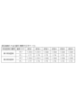
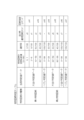
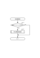
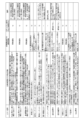
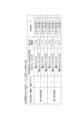
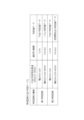
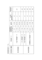
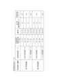
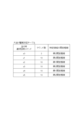
[1-4-1.設定値毎の大当り確率]
図8は、第1のパチンコ遊技機における設定値毎の大当り確率(概算)を示すテーブル
の一例である。図8に示されるように、第1のパチンコ遊技機では、上述の設定キー17
4やバックアップクリアスイッチ176(いずれも図6参照)等を用いて、例えば設定1
~設定6といった複数の設定値のうちいずれか一の設定値にセットすることができる。こ
のような設定機能付きパチンコ遊技機の場合、大当り確率は設定値に応じて異なっており
、メインCPU201は、セットされた設定値に基づいて特別図柄の当り判定処理を実行
する。
[1-4-1. Jackpot Probability for Each Setting Value]
8 is an example of a table showing the probability of winning (approximate) for each setting value in the first pachinko gaming machine. As shown in FIG. 8, in the first pachinko gaming machine, the setting
4 or backup clear switch 176 (see FIG. 6) to set, for example, setting 1
The setting value can be set to any one of a plurality of setting values, such as setting 1 through setting 6. In the case of such a pachinko game machine with a setting function, the probability of a big win differs according to the setting value, and the
具体的には、確変制御が実行されない確変フラグがオフの遊技状態(本実施例では例え
ば通常遊技状態および低確時短遊技状態)における大当り確率は、第1特別図柄の当り判
定処理および第2特別図柄の当り判定処理のいずれが実行された場合であっても、例えば
、設定1で約319分の1、設定2で約314分の1、設定3で約309分の1、設定4
で約304分の1、設定5で約299分の1、設定6で約294分の1となっている。ま
た、確変制御が実行される確変フラグがオンの遊技状態(本実施例では例えば高確時短遊
技状態および高確非時短遊技状態)における大当り確率は、設定1で約77分の1、設定
2で約76分の1、設定3で約75分の1、設定4で約74分の1、設定5で約73分の
1、設定6で約72分の1となっている。なお、小当り確率については図8に示されてい
ないが、設定値に応じて異なるようにしてもよいし、設定1~設定6で共通の確率として
もよい。
Specifically, the probability of a jackpot in a game state in which the probability jackpot control is not executed and the probability jackpot flag is off (for example, in the normal game state and the low probability time-saving game state in this embodiment), regardless of whether the hit determination process for the first special symbol or the hit determination process for the second special symbol is executed, is, for example, about 1 in 319 in setting 1, about 1 in 314 in setting 2, about 1 in 309 in setting 3, and about 1 in 4 in setting 5.
1 in 304 for setting 1, 1 in 299 for setting 5, and 1 in 294 for setting 6. The probability of a big win in a game state where the probability variable control is executed and the probability variable flag is on (for example, in this embodiment, the high probability time-saving game state and the high probability non-time-saving game state) is about 1 in 77 for setting 1, about 1 in 76 for setting 2, about 1 in 75 for setting 3, about 1 in 74 for setting 4, about 1 in 73 for setting 5, and about 1 in 72 for setting 6. The probability of a small win is not shown in FIG. 8, but it may be different depending on the setting value, or it may be a common probability for
また、本実施例では、全ての設定値においてそれぞれ大当り確率が異なっているが、こ
れに限定されず、例えば、設定1と設定2とで共通の大当り確率、設定3と設定4とで共
通の大当り確率、設定5と設定6とで共通の大当り確率といったように、複数の設定値で
大当り確率を同じにしてもよい。
In addition, in this embodiment, the probability of a jackpot is different for each setting value, but this is not limited to this. For example, the probability of a jackpot may be the same for multiple setting values, such as a common jackpot probability for
また、本実施例では、設定値に応じて大当り確率が異なっているが、遊技者にとっての
有利度合いが設定値に応じて異なれば、設定値に応じて異なる対象が必ずしも大当り確率
に限定されない。例えば、特定の入賞口に遊技球が入賞すると大当り遊技状態に制御され
るようなパチンコ遊技機であれば、設定値に応じて特定の入賞口への入賞確率を異ならせ
るようにしてもよい。なお、パチンコ遊技機を、設定機能付きパチンコ遊技機とすること
は必須ではない。
In this embodiment, the probability of winning a jackpot is different depending on the setting value, but if the degree of advantage for the player differs depending on the setting value, the target that differs depending on the setting value is not necessarily limited to the probability of winning a jackpot. For example, in a pachinko game machine that is controlled to a jackpot game state when a game ball enters a specific winning hole, the probability of winning a prize in the specific winning hole may be made different depending on the setting value. Note that it is not essential that the pachinko game machine be a pachinko game machine with a setting function.
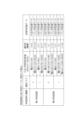
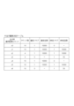
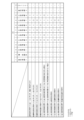
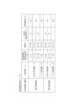
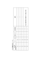
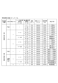
[1-4-2.特別図柄の当り判定テーブル]
図9は、第1のパチンコ遊技機が備える主制御回路200のメインROM202に記憶
されている特別図柄の当り判定テーブルの一例である。なお、図9に示される特別図柄の
当り判定テーブルは、図8に示される設定1の場合を一例として示したものである。
[1-4-2. Special symbol winning judgment table]
9 is an example of a special symbol winning judgment table stored in the
特別図柄の当り判定テーブルは、特別図柄の当り判定処理において参照されるテーブル
、すなわち、第1始動口120または第2始動口140A,140Bに遊技球が入賞した
際に取得される大当り判定用乱数値に基づいて「大当り」、「小当り」または「ハズレ」
を抽選により決定する際に参照されるテーブルである。なお、本実施例では、第1特別図
柄の当り判定処理における抽選対象は「大当り」および「ハズレ」のみである。これに対
し、第2特別図柄の当り判定処理における抽選対象は「大当り」、「小当り」および「ハ
ズレ」である。ただし、第1特別図柄の当り判定処理における抽選対象に「小当り」を含
めるようにしてもよい。
The special symbol winning judgment table is a table referred to in the winning judgment process of the special symbol, that is, a "big win", a "small win" or a "miss" based on a random number value for winning judgment obtained when a game ball enters the
This is a table to be referred to when determining by lottery. In this embodiment, the lottery targets in the hit determination process of the first special symbol are only "big hit" and "miss". In contrast, the lottery targets in the hit determination process of the second special symbol are "big hit", "small hit" and "miss". However, the lottery targets in the hit determination process of the first special symbol may include "small hit".
大当り判定用乱数値は、上述したとおり、特別図柄の当り判定処理に用いられる乱数値
である。本実施例において、大当り判定用乱数値は、0~65535(65536種類)
の中から抽出される。ただし、発生する乱数値の範囲は上記に限られない。
As described above, the random number value for determining a jackpot is a random number value used in the process of determining whether or not a special symbol is selected. In this embodiment, the random number value for determining a jackpot is 0 to 65535 (65536 types).
However, the range of the generated random numbers is not limited to the above.
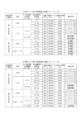
本実施例では、第1特別図柄の当り判定処理において、抽出された大当り判定用乱数値
に基づいて「大当り」または「ハズレ」に決定される。第1特別図柄の当り判定テーブル
には、確変フラグの値(0または1)毎に、「大当り」に決定される大当り判定用乱数値
の範囲(幅)とこれに対応する大当り判定値データとの関係、および、「ハズレ」に決定
される大当り判定用乱数値の範囲(幅)とこれに対応するハズレ判定値データとの関係が
規定されている。
In this embodiment, in the hit determination process of the first special symbol, a "hit" or a "miss" is determined based on the extracted random number value for hit determination. In the hit determination table of the first special symbol, the relationship between the range (width) of the random number value for hit determination determined as a "hit" and the corresponding hit determination value data, and the relationship between the range (width) of the random number value for hit determination determined as a "miss" and the corresponding miss determination value data are specified for each value (0 or 1) of the probability variable flag.
なお、本明細書において、確変フラグの値が「0」の場合、確変フラグがオフであり、
確変フラグの値が「1」の場合、確変フラグがオンである。
In this specification, when the value of the probability flag is "0", the probability flag is off,
When the value of the probability variable flag is "1", the probability variable flag is on.
また、第2特別図柄の当り判定処理において、抽出された大当り判定用乱数値に基づい
て「大当り」、「小当り」または「ハズレ」に決定される。第2特別図柄の当り判定テー
ブルには、確変フラグの値(0または1)毎に、「大当り」に決定される大当り判定用乱
数値の範囲(幅)とこれに対応する大当り判定値データとの関係、「小当り」に決定され
る大当り判定用乱数値の範囲(幅)とこれに対応する小当り判定値データとの関係、およ
び、「ハズレ」に決定される大当り判定用乱数値の範囲(幅)とこれに対応するハズレ判
定値データとの関係が規定される。
In addition, in the hit determination process of the second special symbol, a "hit", a "small hit" or a "miss" is determined based on the extracted random number value for hit determination. In the hit determination table of the second special symbol, for each value (0 or 1) of the probability variable flag, the relationship between the range (width) of the random number value for hit determination determined as a "hit" and the corresponding hit determination value data, the relationship between the range (width) of the random number value for hit determination determined as a "small hit" and the corresponding small hit determination value data, and the relationship between the range (width) of the random number value for hit determination determined as a "miss" and the corresponding miss determination value data are specified.
本実施例では、第1特別図柄の当り判定処理時に確変フラグがオフであって、抽出され
た大当り判定用乱数値が0~204のいずれかである場合は「大当り」と判定され、当落
判定値データは「大当り判定値データ」に決定される。また、第1特別図柄の当り判定処
理時に確変フラグがオフであって、抽出された大当り判定用乱数値が0~204のいずれ
でもない場合は「ハズレ」と判定され、判定値データは「ハズレ判定値データ」に決定さ
れる。
In this embodiment, if the probability variable flag is off during the hit determination process of the first special symbol and the extracted random number value for the hit determination is any one of 0 to 204, it is determined as a "hit" and the hit/loss determination value data is determined as "hit determination value data." Also, if the probability variable flag is off during the hit determination process of the first special symbol and the extracted random number value for the hit determination is not any one of 0 to 204, it is determined as a "miss" and the determination value data is determined as "miss determination value data."
また、第1特別図柄の当り判定処理時に確変フラグがオンであって、抽出された大当り
判定用乱数値が0~850のいずれかである場合は「大当り」と判定され、判定値データ
は「大当り判定値データ」に決定される。また、第1特別図柄の当り判定処理時に確変フ
ラグがオンであって、抽出された大当り判定用乱数値が0~850のいずれでもない場合
、「ハズレ」と判定され、判定値データは「ハズレ判定値データ」に決定される。
In addition, if the probability variable flag is on during the hit determination process of the first special symbol and the extracted random number value for the hit determination is any one of 0 to 850, it is determined as a "hit" and the determination value data is determined as "hit determination value data." In addition, if the probability variable flag is on during the hit determination process of the first special symbol and the extracted random number value for the hit determination is not any one of 0 to 850, it is determined as a "miss" and the determination value data is determined as "miss determination value data."
同様に、第2特別図柄の当り判定処理時に確変フラグがオフであって、抽出された大当
り判定用乱数値が0~204のいずれかである場合は「大当り」と判定され、判定値デー
タは「大当り判定値データ」に決定される。また、第2特別図柄の当り判定処理時に確変
フラグがオフであって、抽出された大当り判定用乱数値が205~22049のいずれか
である場合は「小当り」と判定され、判定値データは「小当り判定値データ」に決定され
る。さらに、第2特別図柄の当り判定処理時に確変フラグがオフであって、抽出された大
当り判定用乱数値が0~22049のいずれでもない場合は「ハズレ」と判定され、判定
値データは「ハズレ判定値データ」に決定される。
Similarly, if the probability variable flag is off during the hit determination process of the second special symbol and the extracted random number value for the big hit determination is any one of 0 to 204, it is determined as a "big hit" and the determination value data is determined as "big hit determination value data". Also, if the probability variable flag is off during the hit determination process of the second special symbol and the extracted random number value for the big hit determination is any one of 205 to 22049, it is determined as a "small hit" and the determination value data is determined as "small hit determination value data". Furthermore, if the probability variable flag is off during the hit determination process of the second special symbol and the extracted random number value for the big hit determination is not any one of 0 to 22049, it is determined as a "miss" and the determination value data is determined as "miss determination value data".
また、第2特別図柄の当り判定処理時に確変フラグがオンであって、抽出された大当り
判定用乱数値が0~850のいずれかである場合は「大当り」と判定され、判定値データ
は「大当り判定値データ」に決定される。また、第2特別図柄の当り判定処理時に確変フ
ラグがオンであって、抽出された大当り判定用乱数値が851~22695のいずれかで
ある場合は「小当り」と判定され、判定値データは「小当り判定値データ」に決定される
。さらに、第2特別図柄の当り判定処理時に確変フラグがオンであって、抽出された大当
り判定用乱数値が0~22695のいずれでもない場合は「ハズレ」と判定され、判定値
データは「ハズレ判定値データ」に決定される。
In addition, if the probability variable flag is on during the hit determination process of the second special symbol and the extracted random number value for the big hit determination is any one of 0 to 850, it is determined as a "big hit" and the determination value data is determined as "big hit determination value data". In addition, if the probability variable flag is on during the hit determination process of the second special symbol and the extracted random number value for the big hit determination is any one of 851 to 22695, it is determined as a "small hit" and the determination value data is determined as "small hit determination value data". In addition, if the probability variable flag is on during the hit determination process of the second special symbol and the extracted random number value for the big hit determination is not any one of 0 to 22695, it is determined as a "miss" and the determination value data is determined as "miss determination value data".
[1-4-3.特別図柄判定テーブル]
図10は、第1のパチンコ遊技機が備える主制御回路200のメインROM202に記
憶されている特別図柄判定テーブルの一例である。
[1-4-3. Special symbol determination table]
FIG. 10 is an example of a special symbol determination table stored in the
特別図柄判定テーブルは、第1始動口120または第2始動口140A、140Bに遊
技球が入賞した際に取得される特別図柄の図柄乱数値と先述の当落判定値データとに基づ
いて、停止図柄を決定付ける「当り時選択図柄コマンド」および「図柄指定コマンド」を
選択する際に参照されるテーブルである。「当り時選択図柄コマンド」は、特別図柄の当
り判定処理の結果が大当りであった場合に、大当り種類に応じて定められる当り図柄を指
定するためのコマンドであり、「図柄指定コマンド」は、特別図柄の可変表示の停止時に
表示される図柄を指定するためのコマンドである。特別図柄の図柄乱数値は、例えば0~
99(100種類)の中から抽出される。
The special symbol determination table is a table that is referenced when selecting a "symbol selection command at win" and a "symbol designation command" that determine the symbols to be stopped based on the symbol random number value of the special symbol obtained when the game ball enters the
It is selected from 99 (100 types).
図10に示される特別図柄判定テーブルによれば、第1特別図柄の当り判定処理の結果
として大当り判定値データが得られた場合、例えば、当り時選択図柄コマンドおよび図柄
指定コマンドは以下のように選択される。すなわち、第1特別図柄の図柄乱数値が0また
は1である場合、当り時選択図柄コマンドとして「z0」が選択され、図柄指定コマンド
として「zA1」が選択される。また、第1特別図柄の図柄乱数値が2~9のいずれかで
ある場合、当り時選択図柄コマンドとして「z1」が選択され、図柄指定コマンドとして
「zA1」が選択される。また、第1特別図柄の図柄乱数値が10~59のいずれかであ
る場合、当り時選択図柄コマンドとして「z2」が選択され、図柄指定コマンドとして「
zA2」が選択される。さらに、第1特別図柄の図柄乱数値が60~99のいずれかであ
る場合、当り時選択図柄コマンドとして「z3」が選択され、図柄指定コマンドとして「
zA2」が選択される。
According to the special symbol determination table shown in FIG. 10, when jackpot determination value data is obtained as a result of the hit determination process for the first special symbol, for example, the hit-time selection symbol command and the symbol designation command are selected as follows. That is, when the symbol random number value of the first special symbol is 0 or 1, "z0" is selected as the hit-time selection symbol command, and "zA1" is selected as the symbol designation command. Also, when the symbol random number value of the first special symbol is any value between 2 and 9, "z1" is selected as the hit-time selection symbol command, and "zA1" is selected as the symbol designation command. Also, when the symbol random number value of the first special symbol is any value between 10 and 59, "z2" is selected as the hit-time selection symbol command, and "zA2" is selected as the symbol designation command.
Furthermore, if the symbol random number value of the first special symbol is any one of 60 to 99, "z3" is selected as the winning symbol selection command, and "
zA2" is selected.
また、第1特別図柄の当り判定処理の結果としてハズレ判定値データが得られた場合、
第1特別図柄の図柄乱数値が0~99のいずれであっても、当り時選択図柄コマンドは選
択されず、図柄指定コマンドは「zA3」が選択される。
In addition, when the miss judgment value data is obtained as a result of the hit judgment process of the first special pattern,
Regardless of whether the random number value of the first special symbol is 0 to 99, the symbol selection command is not selected when a winning combination occurs, and the symbol designation command "zA3" is selected.
また、第2特別図柄の当り判定処理の結果として大当り判定値データが得られた場合、
例えば、当り時選択図柄コマンドおよび図柄指定コマンドは以下のように選択される。す
なわち、第2特別図柄の図柄乱数値が0~29のいずれかである場合、当り時選択図柄コ
マンドとして「z4」が選択され、図柄指定コマンドとして「zA4」が選択される。ま
た、第2特別図柄の図柄乱数値が30~59のいずれかである場合、当り時選択図柄コマ
ンドとして「z5」が選択され、図柄指定コマンドとして「zA5」が選択される。さら
に、第2特別図柄の図柄乱数値が60~99のいずれかである場合、当り時選択図柄コマ
ンドとして「z6」が選択され、図柄指定コマンドとして「zA5」が選択される。
In addition, when the jackpot determination value data is obtained as a result of the hit determination process of the second special pattern,
For example, the winning symbol selection command and the symbol designation command are selected as follows. That is, when the symbol random number value of the second special symbol is any of 0 to 29, "z4" is selected as the winning symbol selection command, and "zA4" is selected as the symbol designation command. When the symbol random number value of the second special symbol is any of 30 to 59, "z5" is selected as the winning symbol selection command, and "zA5" is selected as the symbol designation command. When the symbol random number value of the second special symbol is any of 60 to 99, "z6" is selected as the winning symbol selection command, and "zA5" is selected as the symbol designation command.
また、第2特別図柄の当り判定処理の結果として小当り判定値データが得られた場合、
特別図柄の図柄乱数値が0~99のいずれであっても、当り時選択図柄コマンドとして「
z7」が選択され、図柄指定コマンドとして「zA6」が選択される。
In addition, when small hit determination value data is obtained as a result of the hit determination process of the second special pattern,
Regardless of whether the random number of the special symbol is 0 to 99, the symbol selection command when the special symbol is selected is "
"z7" is selected, and "zA6" is selected as the symbol designation command.
なお、第2特別図柄の当り判定処理の結果として小当り判定値データが得られると、メ
インCPU201は、小当り遊技制御処理を実行する。小当り遊技制御処理では、例えば
小当り用シャッタ153(図6参照)を作動させて、小当り用大入賞口151(図4参照
)への遊技球の入賞(通過)が可能または容易な開放状態となる制御を実行し、賞球が払
い出され得る。
When the small win determination value data is obtained as a result of the hit determination process of the second special symbol, the
また、第2特別図柄の当り判定処理の結果が「ハズレ」であった場合、特別図柄の図柄
乱数値が0~99のいずれであっても、当り時選択図柄コマンドは選択されず、図柄指定
コマンドは「zA7」が選択される。
In addition, if the result of the winning determination process for the second special symbol is "miss," even if the symbol random number value of the special symbol is any value from 0 to 99, the symbol selection command at the time of winning is not selected, and the symbol designation command "zA7" is selected.
なお、本実施例では、特別図柄の当り判定テーブル(図9参照)を参照して、抽出され
た大当り判定用乱数値に基づいて当落判定値データを決定し、その後、特別図柄判定テー
ブル(図10参照)を参照して、特別図柄の図柄乱数値に基づいて当り時選択図柄コマン
ドおよび図柄指定コマンドを決定するといった所謂2段階抽選を行うようにしているが、
これに限られない。例えば、抽出された大当り判定用乱数値と特別図柄の図柄乱数値とに
基づいて、特別図柄の当落、当り時選択図柄コマンドおよび図柄指定コマンドを決定する
といった所謂1段階抽選を行うようにしてもよい。
In this embodiment, the winning/losing judgment value data is determined based on the extracted random number value for jackpot judgment by referring to the winning judgment table for the special symbols (see FIG. 9), and then the winning selection symbol command and the symbol designation command are determined based on the symbol random number value of the special symbols by referring to the special symbol judgment table (see FIG. 10). In this way, a so-called two-stage lottery is performed.
For example, a so-called one-stage lottery may be performed to determine the winning or losing of the special symbol, the winning selection symbol command, and the symbol designation command based on the extracted random number value for determining the big win and the symbol random number value of the special symbol.
[1-4-4.大当り種類決定テーブル]
図11は、第1のパチンコ遊技機が備える主制御回路200のメインROM202に記
憶されている大当り種類決定テーブルの一例である。大当り種類決定テーブルは、特別図
柄の図柄乱数値に対応して決定される当り時選択図柄コマンドに応じて、大当り遊技状態
において実行されるラウンド数、確変フラグの値、確変回数、時短フラグの値、および、
時短回数等、大当りの種類を決定する際に参照される。
[1-4-4. Jackpot type determination table]
11 is an example of a jackpot type determination table stored in the
This is referred to when determining the type of jackpot, such as the number of time-saving rounds.
なお、本明細書において、確変フラグの場合と同様に、時短フラグの値が「0」の場合
が時短フラグオフであり、時短フラグの値が「1」の場合が時短フラグオンである。
In this specification, as in the case of the special bonus flag, when the value of the time-saving flag is "0", the time-saving flag is off, and when the value of the time-saving flag is "1", the time-saving flag is on.
本実施例では、第1特別図柄の当り判定処理の結果が「大当り」であった場合、大当り
種類は次のとおり決定される。例えば、当り時選択図柄コマンドが「z0」の場合、ラウ
ンド数が「10」、確変フラグがオン、確変回数が「10000」、時短フラグがオフに
決定される。また、当り時選択図柄コマンドが「z1」の場合、ラウンド数が「10」、
確変フラグがオン、確変回数が「10000」、時短フラグがオン、時短回数が「100
00」に決定される。また、当り時選択図柄コマンドが「z2」の場合、ラウンド数が「
4」、確変フラグがオン、確変回数が「10000」、時短フラグがオン、時短回数が「
10000」に決定される。さらに、当り時選択図柄コマンドが「z3」の場合、ラウン
ド数が「4」、確変フラグがオフ、時短フラグがオン、時短回数が「50」に決定される
。
In this embodiment, if the result of the hit determination process of the first special symbol is a "jackpot", the type of the jackpot is determined as follows. For example, if the hit selection symbol command is "z0", the number of rounds is determined to be "10", the probability bonus flag is on, the number of probability bonuses is "10000", and the time-saving flag is off. Also, if the hit selection symbol command is "z1", the number of rounds is determined to be "10",
The probability of winning is 10,000. The time-saving flag is on. The time-saving flag is on.
00". Also, if the winning symbol command is "z2", the number of rounds is "
4", the probability of winning is on, the probability of winning is 10,000, the time-saving flag is on, and the time-saving number is
Furthermore, if the winning symbol selection command is "z3", the number of rounds is determined to be "4", the probability bonus flag is OFF, the time-saving flag is ON, and the number of time-saving times is determined to be "50".
また、第2特別図柄の当り判定処理の結果が「大当り」であった場合、大当り種類は次
のとおり決定される。例えば、当り時選択図柄コマンドが「z4」の場合、ラウンド数が
「10」、確変フラグがオン、確変回数が「10000」、時短フラグがオフに決定され
る。また、当り時選択図柄コマンドが「z5」の場合、ラウンド数が「10」、確変フラ
グがオン、確変回数が「10000」、時短フラグがオン、時短回数が「10000」に
決定される。さらに、当り時選択図柄コマンドが「z6」の場合、ラウンド数が「10」
、確変フラグがオフ、時短フラグがオン、時短回数が「50」に決定される。
Furthermore, if the result of the hit determination process for the second special symbol is a "jackpot," the type of jackpot is determined as follows. For example, if the symbol command selected when a hit is "z4," the number of rounds is determined to be "10," the special rate flag is on, the number of special rate times is "10,000," and the time-saving flag is off. Also, if the symbol command selected when a hit is "z5," the number of rounds is determined to be "10," the special rate flag is on, the number of special rate times is "10,000," the time-saving flag is on, and the number of time-saving times is "10,000." Furthermore, if the symbol command selected when a hit is "z6," the number of rounds is determined to be "10."
The special bonus flag is turned off, the time-saving flag is turned on, and the number of time-saving times is set to "50."
ただし、図11に示される大当りの種類は一例であって、これに限られない。なお、確
変フラグの値が「0」に決定される場合、確変回数は決定されないが、確変制御が実行さ
れないという意味で確変回数が「0」にセットされるようにしてもよい。
However, the types of jackpots shown in Fig. 11 are examples and are not limited to these. When the value of the probability change flag is determined to be "0", the probability change count is not determined, but the probability change count may be set to "0" in the sense that the probability change control is not executed.
なお、確変回数の「10000」は、大当り遊技状態終了後の遊技状態において実行さ
れる特別図柄の当り判定処理において大当りであると判定される(すなわち次回大当り)
まで、確変制御を継続して実行できる趣旨である。
In addition, the "10000" probability of winning is determined to be a jackpot in the special symbol winning determination process executed in the game state after the jackpot game state ends (i.e., the next jackpot).
The purpose is to be able to continue executing the variable probability control until the end.
[1-4-5.特別図柄の変動パターンテーブル]
図12は、第1のパチンコ遊技機の特別図柄の変動パターンテーブルの一例であって、
(A)低スタート用の特別図柄の変動パターンテーブル、(B)高スタート用の特別図柄
の変動パターンテーブルである。なお、図12中の「演出内容」の欄は、分かりやすいよ
うに便宜上示したものである。メインCPU201は、第1始動口120への遊技球の入
賞に基づくときは第1特別図柄の変動パターンを決定し、第2始動口140A,140B
への遊技球の入賞に基づくときは第2特別図柄の変動パターンを決定する。
[1-4-5. Special symbol variation pattern table]
FIG. 12 is an example of a variation pattern table of special symbols of the first pachinko gaming machine.
(A) A variation pattern table of special symbols for low start, (B) A variation pattern table of special symbols for high start. Note that the "Performance Content" column in FIG. 12 is shown for the sake of convenience. The
When it is based on the winning of the gaming ball into the slot, the variation pattern of the second special symbol is determined.
左打ちが推奨される通常遊技状態では、例えば図12(A)に示される低スタート用の
特別図柄の変動パターンテーブルを参照して特別図柄の変動パターンが決定される。
In a normal game state in which left-handed play is recommended, the variation pattern of the special symbols is determined by referring to a variation pattern table of special symbols for a low start, for example, as shown in FIG. 12(A).
一方、右打ちが推奨される遊技状態、すなわち、高確時短遊技状態、高確非時短遊技状
態または低確時短遊技状態では、例えば図12(B)に示される高スタート用の特別図柄
の変動パターンテーブルを参照して特別図柄の変動パターンが決定される。
On the other hand, in a gaming state in which right-hitting is recommended, i.e., a high-probability time-saving gaming state, a high-probability non-time-saving gaming state, or a low-probability time-saving gaming state, the variation pattern of the special symbol is determined by referring to the variation pattern table of the special symbol for a high start shown, for example, in Figure 12 (B).
図12(A)および(B)に示されるように、特別図柄の変動パターンは、特別図柄の
種別、特別図柄の当り判定処理の結果(当落)、リーチ判定用乱数値、および、演出選択
用乱数値に基づいて決定される。ただし、これに限られず、上記のいずれかに代えてまた
は加えて他の値等に基づいて決定されるようにしてもよい。
As shown in Figures 12(A) and 12(B), the variation pattern of the special symbol is determined based on the type of the special symbol, the result of the special symbol hit determination process (win or lose), the reach determination random number value, and the performance selection random number value. However, it is not limited to this, and it may be determined based on other values instead of or in addition to any of the above.
なお、リーチ判定用乱数値は例えば0~249(250種類)の中から抽出され、演出
選択用乱数値は例えば0~99(100種類)の中から抽出される。ただし、発生する乱
数値の範囲は上記に限られない。
The random number for reach determination is selected from, for example, 0 to 249 (250 types), and the random number for effect selection is selected from, for example, 0 to 99 (100 types). However, the range of the generated random numbers is not limited to the above.
高スタート用の特別図柄の変動パターンテーブルを参照して特別図柄の変動パターンを
決定した場合、低スタート用の特別図柄の変動パターンテーブルを参照して特別図柄の変
動パターンを決定した場合と比べて、単位時間あたりの特別図柄の可変表示回数の期待値
が大きい。とくに、低スタート用の特別図柄の変動パターンテーブルを参照して特別図柄
の変動パターンを決定する場合、第2特別図柄は、例えば概ね600000msec(例
えば、長変動A~C)と極めて長時間にわたって可変表示が行われる。一方、高スタート
用の特別図柄の変動パターンテーブルを参照して特別図柄の変動パターンを決定する場合
、第2特別図柄は、例えば1000msec(例えば、超速変動)と極めて短時間だけ可
変表示が行われる。
When the special symbol variation pattern is determined by referring to the special symbol variation pattern table for high start, the expected number of times the special symbol is variably displayed per unit time is larger than when the special symbol variation pattern is determined by referring to the special symbol variation pattern table for low start. In particular, when the special symbol variation pattern is determined by referring to the special symbol variation pattern table for low start, the second special symbol is variably displayed for an extremely long time, for example, about 600,000 msec (for example, long variation A to C). On the other hand, when the special symbol variation pattern is determined by referring to the special symbol variation pattern table for high start, the second special symbol is variably displayed for an extremely short time, for example, 1,000 msec (for example, super-fast variation).
メインCPU201は、決定した変動パターン情報をサブCPU301に送信する。サ
ブCPU301は、メインCPU201から送信された変動パターン情報に基づいて、表
示装置7の表示領域に表示される表示演出や、スピーカ32から出力される音演出を制御
する。
The
なお、図12には示されていないが、設定値毎に、例えば演出選択用乱数値の範囲を変
えて、決定される特別図柄の変動パターン(可変表示時間)が異なるようにしてもよい。
Although not shown in FIG. 12, the variation pattern (variable display time) of the special symbol to be determined may be different for each set value, for example by changing the range of the random number value for effect selection.
また、本実施例では、例えば通常遊技状態では低スタート用の特別図柄の変動パターン
テーブルを参照して特別図柄の変動パターンを決定し、例えば高確時短遊技状態、高確非
時短遊技状態または低確時短遊技状態では高スタート用の特別図柄の変動パターンテーブ
ルを参照して特別図柄の変動パターンを決定するようにしたが、これに限られない。
In addition, in this embodiment, for example, in a normal game state, the variation pattern of the special pattern is determined by referring to a variation pattern table of special patterns for a low start, and, for example, in a high-probability time-saving game state, a high-probability non-time-saving game state, or a low-probability time-saving game state, the variation pattern of the special pattern is determined by referring to a variation pattern table of special patterns for a high start, but this is not limited to this.
[1-5.主制御処理]
次に、図13~図39を参照して、主制御回路200のメインCPU201により実行
される各種処理(各種モジュール)の内容について説明する。
[1-5-1.主制御メイン処理]
次に、図13~図16を参照して、メインCPU201により実行されるメイン処理(
主制御メイン処理)について説明する。図13~図16は、第1のパチンコ遊技機におけ
る主制御メイン処理の一例を示すフローチャートである。
[1-5. Main control processing]
Next, the contents of various processes (various modules) executed by the
[1-5-1. Main control main processing]
Next, referring to FIG. 13 to FIG. 16, the main process (
13 to 16 are flow charts showing an example of the main control process in the first pachinko gaming machine.
メインCPU201は、先ず、電断信号がHighレベルであるか否かを判定する(S
11)。なお、図示しないが、メインCPU201は、スタックポインタの設定や割込み
ベクタテーブルのアドレスの設定をS11に先だって行うことは言うまでもない。
The
11) Although not shown, it goes without saying that the
S11において電断信号がHighレベルでないと判定された場合(S11がNO判定
の場合)、メインCPU201は、S11の判定処理を繰り返す。
If it is determined in S11 that the power interruption signal is not at a high level (if S11 is a NO determination), the
一方、S11において電断信号がHighレベルであると判定された場合(S11がY
ES判定の場合)、メインCPU201は、処理を、S12に移す。
On the other hand, if it is determined in S11 that the power interruption signal is at a high level (S11 is Y
In the case of ES determination, the
S12において、メインCPU201は、バックアップクリアスイッチ176および設
定キー174のフラグ管理処理を行う(S12)。この処理では、バックアップクリアス
イッチ176のオン/オフ状態、および、設定キー174のオン/オフ状態の退避処理が
行われる。すなわち、バックアップクリアスイッチ176および設定キー174のオン/
オフ状態を、メインRAM203内の起動制御フラグ領域に格納する。また、この処理で
は、遊技許可フラグがオフにセットされる。メインCPU201は、S12の処理を実行
した後、処理を、S13に移す。
In S12, the
The OFF state is stored in the start control flag area in the
S13において、メインCPU201は、ウェイト処理を行う。この処理では、サブ制
御回路300側の起動待ちが行われる。この場合の起動待ち時間(ウェイト期間)は、例
えば12000.07msecである。メインCPU201は、S13の処理を実行した
後、処理を、S14に移す。
In S13, the
なお、サブ制御回路300側の起動待ちを行っている間、メインCPU201は、例え
ば、割込要求信号のチェック処理、割込要求信号発生時のWDTの出力処理、所定のタイ
ミングでの各種センサ初期化信号の出力処理等を行うようにしてもよい。
In addition, while waiting for the
S14において、メインCPU201は、起動前(前回)の電断が正常電断であったか
否かを判定する。この処理では、メインRAM203内の電断検知フラグ領域に格納され
た値に基づいて、正常電断であるか異常電断であるかが判定される。
In S14, the
S14において正常電断でなかったと判定された場合(S14がNO判定の場合)、メ
インCPU201は、処理を、S18に移す。
If it is determined in S14 that the power interruption was not normal (if S14 is a NO determination), the
一方、S14において正常電断であったと判定された場合(S14がYES判定の場合
)、メインCPU201は、メインRAM203内に格納された作業領域のチェックサム
値を算出し(S15)、その後、作業領域のチェックサム値の照合処理を行う(S16)
。メインCPU201は、S16の処理を実行した後、処理を、S17に移す。
On the other hand, if it is determined in S14 that the power interruption was normal (if S14 is judged as YES), the
After executing the process of S16, the
S17において、メインCPU201は、照合結果が異常であるか否かを判定する。
In S17, the
S17において照合結果が異常でないすなわち正常であると判定された場合(S17が
NO判定の場合)、メインCPU201は、処理を、S22に移す。なお、S22以降の
処理については後述する。
If it is determined in S17 that the collation result is not abnormal, that is, is normal (NO in S17), the
一方、S17において照合結果が異常であるすなわち正常でないと判定された場合(S
17がYES判定の場合)、メインCPU201は、処理を、S18に移す。
On the other hand, if it is determined in S17 that the collation result is abnormal, i.e., abnormal (S
17 is a YES judgement), the
S18において、メインCPU201は、設定キー174およびバックアップクリアス
イッチ176のうち、少なくともいずれか一方がオフであるか否かを判定する。すなわち
、設定キー174およびバックアップクリアスイッチ176の両方がオンである場合はN
O判定となり、設定キー174およびバックアップクリアスイッチ176の両方がオフで
ある場合、および、設定キー174およびバックアップクリアスイッチ176のいずれか
一方がオフである場合はYES判定となる。
In S18, the
If both the setting
S18において設定キー174およびバックアップクリアスイッチ176の少なくとも
いずれか一方がオフでないすなわち両方ともオンであると判定された場合(S18がNO
判定の場合)、メインCPU201は、処理を、S21に移す。なお、S21の処理につ
いては後述する。
If it is determined in S18 that at least one of the setting
If so, the
一方、S18において設定キー174およびバックアップクリアスイッチ176のうち
少なくともいずれか一方がオフであると判定された場合(S18がYES判定の場合)、
メインCPU201は、処理を、S19に移す。
On the other hand, if it is determined in S18 that at least one of the setting
The
S19において、メインCPU201は、外部端子のセキュリティ信号をオンにセット
する。メインCPU201は、S19の処理を実行した後、処理を、S20に移す。
In S19, the
S20において、メインCPU201は、性能表示モニタ170(図6参照)にエラー
表示処理を行う。この処理は、性能表示モニタ170に信号が出力されるI/Oポート2
05の出力ポートに、エラー表示用のデータをセットする。これにより、性能表示モニタ
170内の所定のLEDが点灯し、エラー表示が行われる。メインCPU201は、S2
0の処理を実行した後、永久ループに入る。
In S20, the
The
After executing the process for 0, an endless loop is entered.
このように、前回の電断が正常電断でなかった場合や、メインRAM203内に格納さ
れた作業領域のチェックサム値の照合結果が正常でなかった場合には、設定キー174お
よびバックアップクリアスイッチ176の両方がオンであると判定されるまで、第1のパ
チンコ遊技機において遊技の実行が可能とならない。
In this way, if the previous power outage was not normal, or if the comparison result of the checksum value of the working area stored in the
次に、S21の処理について説明する。S21において、メインCPU201は、設定
変更であることを示す値をメインRAM203内の起動制御フラグ領域に格納する。この
処理は、異常起動時に行われる処理であり、設定変更であることを示す値を再度格納する
ようにしたものである。メインCPU201は、S21の処理を実行した後、処理を、S
22に移す。
Next, the process of S21 will be described. In S21, the
Move to 22.
S22において、メインCPU201は、メインRAM203内のXINT検知フラグ
領域および電断検知フラグ領域のクリア処理を行う(S22)。メインCPU201は、
S22の処理を実行した後、処理を、S23に移す。
In S22, the
After executing the process of S22, the process proceeds to S23.
S23において、メインCPU201は、起動状態判定処理を行う。この処理では、メ
インRAM203内の起動制御フラグ領域に格納された起動制御フラグの値に基づいて、
現在の起動状態(電断復帰/設定変更/設定確認/RAMクリア)を判定する。メインC
PU201は、S23の処理を実行した後、処理を、S24に移す。
In S23, the
Determine the current startup state (power failure recovery/setting change/setting confirmation/RAM clear). Main C
After executing the process of S23, the
S24において、メインCPU201は、起動時のRAM設定処理を行う。この処理で
は、フラグ等を管理するメインRAM203内の作業領域(揮発性領域)のクリア処理(
例えば作業領域の構築およびアドレス設定等)が行われる。なお、この処理は、電断復帰
時と初期化時とで共通して行われるものであって、バックアップ領域はクリアされない。
メインCPU201は、S24の処理を実行した後、処理を、S25に移す。
In S24, the
For example, the creation of a working area and address setting are performed. This process is performed both when power is restored after a power outage and when the system is initialized, and the backup area is not cleared.
After executing the process of S24, the
S25において、メインCPU201は、起動時初期設定処理を行う。この処理では、
現在の起動状態(電断復帰/設定変更/設定確認/RAMクリア)に応じた初期設定処理
が行われる。なお、起動時初期設定処理の詳細については、図17を参照して後述する。
メインCPU201は、S25の処理を実行した後、処理を、S26に移す。
In S25, the
An initial setting process is performed according to the current startup state (power failure recovery/setting change/setting confirmation/RAM clear). Details of the startup initial setting process will be described later with reference to FIG.
After executing the process of S25, the
S26において、メインCPU201は、割込禁止処理を行う。メインCPU201は
、S26の処理を実行した後、処理を、S27に移す。
In S26, the
S27において、メインCPU201は、電断処理を行う。メインCPU201は、S
27の処理を実行した後、処理を、S28に移す。なお、電断処理の詳細については、図
18を参照して後述する。
In S27, the
After executing the process of S27, the process proceeds to S28. Details of the power cut process will be described later with reference to FIG.
S28において、メインCPU201は、初期値乱数の更新処理を行う。この処理では
、各種乱数カウンタ(例えば、特別図柄の大当り判定用乱数カウンタ等)の初期値乱数の
更新処理が行われる。メインCPU201は、S28の処理を実行した後、処理を、S2
9に移す。
In S28, the
Move to 9.
S29において、メインCPU201は、遊技許可状態であるか否かを判定する。この
判定処理は、遊技許可フラグの値に基づいて行われる。
In S29, the
S29において遊技許可状態でないと判定された場合(S29がNO判定の場合)、メ
インCPU201は、処理を、S30に移す。
When it is determined in S29 that the game is not permitted (when a NO judgment is made in S29), the
一方、S29において遊技許可状態であると判定された場合(S29がYES判定の場
合)、メインCPU201は、処理を、S31に移す。
On the other hand, when it is determined in S29 that the game is permitted (when S29 is judged as YES), the
S30において、メインCPU201は、割込許可処理を行う。メインCPU201は
、S30の処理を実行した後、処理を、S26に戻し、S26以降の処理を行う。
In S30, the
S31において、メインCPU201は、レジスタの退避処理を行う。メインCPU2
01は、S31の処理を実行した後、処理を、S32に移す。
In S31, the
After executing the process of S31, the process proceeds to S32.
S32において、メインCPU201は、性能表示モニタ集計演算処理を行う。この処
理では、各種ベース値の算出および更新が行われる。また、この処理は、メインRAM2
03内の作業領域とは別の領域(領域外)を使用して行われる。メインCPU201は、
S32の処理を実行した後、処理を、S33に移す。
In S32, the
The
After executing the process of S32, the process proceeds to S33.
S33において、メインCPU201は、S31で退避させたレジスタの復帰処理を行
う。メインCPU201は、S33の処理を実行した後、処理を、S34に移す。
In S33, the
S34において、メインCPU201は、割込許可処理を行う。メインCPU201は
、S34の処理を実行した後、処理を、S35に移す。
In S34, the
S35において、メインCPU201は、システム周期時間が経過したか否かを判定す
る。システム周期時間は、例えば、割込み周期(例えば2msec)の3倍である6ms
ecである。
In S35, the
ec.
S35においてシステム周期時間が経過していないと判定された場合(S35がNO判
定の場合)、メインCPU201は、処理をS26の処理に戻し、S26以降の処理を行
う。
If it is determined in S35 that the system cycle time has not elapsed (if a NO determination is made in S35), the
一方、S35においてシステム周期時間が経過したと判定された場合(S35がYES
判定の場合)、メインCPU201は、処理を、S36に移す。
On the other hand, if it is determined in S35 that the system period has elapsed (S35 is YES),
If so, the
S36において、メインCPU201は、メインRAM203の割込みカウンタ領域に
格納された割込みカウンタの値から1減算する処理を3回行う。この処理により、主制御
メイン処理内の割込禁止区間を管理する割込みカウンタの値がリセットされる。メインC
PU201は、S36の処理を実行した後、処理を、S37に移す。
In S36, the
After executing the process of S36, the
なお、本実施例では、主制御メイン処理内において、後述する遊技制御に関する各種処
理(例えば、S37~S44の処理)の実行前に、例えば6msecの割込禁止区間(S
26~S35の処理区間)が設けられる。それゆえ、本実施例では、後述する遊技制御に
関する各種処理が例えば6msec毎(システム周期毎)に実行されることになる。なお
、本実施例では、割込禁止区間を割込み周期の3倍とする例を説明したが、これに限られ
ない。
In this embodiment, in the main control process, before various processes related to game control (for example, the processes of S37 to S44) described later are executed, an interrupt prohibition period of, for example, 6 msec (S
A processing period of S26 to S35 is provided. Therefore, in this embodiment, various processes related to game control described later are executed, for example, every 6 msec (every system cycle). In this embodiment, an example in which the interrupt inhibition period is three times the interrupt cycle has been described, but this is not limited to this.
S37において、メインCPU201は、システムタイマの更新処理を行う。システム
タイマは、システム周期(例えば6msec)を管理するタイマである。システムタイマ
の値は、メインRAM203の作業領域内のシステム周期管理タイマ領域に格納される。
メインCPU201は、S37の処理を実行した後、処理を、S38に移す。
In S37, the
After executing the process of S37, the
S38において、メインCPU201は、主制御コマンド送受信処理を行う。この処理
では、主として、払出制御のコマンド送受信処理が行われる。メインCPU201は、S
38の処理を実行した後、処理を、S39に移す。
In S38, the
After executing the process of S38, the process proceeds to S39.
S39において、メインCPU201は、特別図柄制御処理を行う。この処理では、特
別図柄ゲームにかかわる処理が行われる。この特別図柄制御処理の詳細については、図1
9を参照して後述する。メインCPU201は、S39の処理を実行した後、処理を、S
40に移す。
In S39, the
After executing the process of S39, the
Move to 40.
S40において、メインCPU201は、普通図柄制御処理を行う。この処理にでは、
普通図柄ゲームにかかわる処理が行われる。この普通図柄制御処理の詳細については、図
30を参照して後述する。メインCPU201は、S40の処理を実行した後、処理を、
S41に移す。
In S40, the
The process for the normal symbol game is carried out. Details of the normal symbol control process will be described later with reference to FIG. 30. After carrying out the process of S40, the
Go to S41.
S41において、メインCPU201は、遊技動作表示ユニット制御処理を行う。この
処理では、LEDユニット160の各表示部(例えば、第1特別図柄表示部163、第2
特別図柄表示部164等)に出力する表示データの設定処理が行われる。メインCPU2
01は、S41の処理を実行した後、処理を、S42に移す。
In S41, the
The
After executing the process of S41, the process proceeds to S42.
S42において、メインCPU201は、遊技情報データ生成処理を行う。この処理で
は、外部端子板パルス信号の制御処理、出力データの設定処理、試射試験信号の生成処理
等が行われる。なお、試射試験信号の生成処理は、メインRAM203内の作業領域とは
別の領域(領域外)を使用して行われる。メインCPU201は、S42の処理を実行し
た後、処理を、S43に移す。
In S42, the
S43において、メインCPU201は、ポート出力処理を行う。この処理では、コマ
ンド出力ポート206(図6参照)への出力データのセット(転送)が行われる。メイン
CPU201は、S43の処理を実行した後、処理を、S44に移す。
In S43, the
S44において、メインCPU201は、状態監視処理を行う。この処理では、発射位
置判定処理、遊技異常検知判定処理および払出異常検知判定処理等が行われる。発射位置
判定処理では、発射位置(例えば、右打ちまたは左打ち)に変化があれば、発射位置コマ
ンドが送信予約される。遊技異常検知判定処理では、異常があれば、遊技異常検知コマン
ドが送信予約される。払出異常検知判定処理では、異常があれば、払出異常検知コマンド
が送信予約される。メインCPU201は、S44の処理を実行した後、処理を、S26
に戻し、S26以降の処理を行う。
In S44, the
and executes the processes from S26 onward.
[1-5-2.起動時初期設定処理]
次に、図17を参照して、主制御メイン処理(図13~図16参照)中のS25で行わ
れる起動時初期設定処理について説明する。図17は、第1のパチンコ遊技機における起
動時初期設定処理の一例を示すフローチャートである。
[1-5-2. Initial setting process at startup]
Next, the startup initial setting process performed in S25 in the main control main process (see Figs. 13 to 16) will be described with reference to Fig. 17. Fig. 17 is a flow chart showing an example of the startup initial setting process in the first pachinko gaming machine.
メインCPU201は、先ず、起動制御フラグをロードする処理を行う(S51)。メ
インCPU201は、S51の処理を実行した後、処理を、S52に移す。
The
S52において、メインCPU201は、起動制御フラグの値が電断復帰を示す値であ
るか否かを判定する。
In S52, the
S52において起動制御フラグの値が電断復帰を示す値でないと判定された場合(S5
2がNO判定の場合)、メインCPU201は、処理を、S54に移す。
If it is determined in S52 that the value of the start control flag is not a value indicating power interruption recovery (S5
2 is judged as NO), the
一方、S52において起動制御フラグの値が電断復帰を示す値であると判定された場合
(S52がYES判定の場合)、メインCPU201は、処理を、S53に移す。
On the other hand, if it is determined in S52 that the value of the start-up control flag is a value indicating power interruption recovery (if S52 is determined as YES), the
S53において、メインCPU201は、第2通常遊技前処理を行う。この第2通常遊
技前処理の詳細については、図37を参照して後述する。第2通常遊技前処理が行われる
と、遊技許可フラグがオンにセットされ、遊技許可状態となる。メインCPU201は、
S53の処理を実行した後、起動時初期設定処理を終了し、処理を、主制御メイン処理(
図13~図16参照)に戻す。
In S53, the
After the process of S53 is executed, the startup initial setting process is ended, and the process is returned to the main control main process (
13 to 16).
S54において、メインCPU201は、起動制御フラグの値が設定変更または設定確
認を示す値であるか否かを判定する。
In S54, the
S54において起動状態フラグの値が設定変更または設定確認を示す値でないすなわち
RAMクリアを示す値であると判定された場合(S54がNO判定の場合)、メインCP
U201は、処理を、S56に移す。
If it is determined in S54 that the value of the startup status flag is not a value indicating a setting change or setting confirmation, i.e., a value indicating RAM clear (if NO is determined in S54), the main CPU
U201 transfers the processing to S56.
一方、S54において起動状態フラグの値が設定変更または設定確認を示す値であると
判定された場合(S54がYES判定の場合)、メインCPU201は、処理を、S55
に移す。
On the other hand, if it is determined in S54 that the value of the startup status flag is a value indicating a setting change or setting confirmation (YES in S54), the
Move to.
S55において、メインCPU201は、設定操作コマンドの送信予約処理を行う。な
お、この処理で送信予約された設定操作コマンドは、次回のシステムタイマ割込処理中の
演出制御コマンド送信処理(後述の図32のS242参照)で、サブ制御回路300に向
けて送信される。メインCPU201は、S55の処理を実行した後、起動時初期設定処
理を終了し、処理を、主制御メイン処理(図13~図16参照)に戻す。
In S55, the
S56において、メインCPU201は、第1通常遊技前処理を行う。この第1通常遊
技前処理の詳細については、図36を参照して後述する。第1通常遊技前処理が行われる
と、遊技許可フラグがオンにセットされ、遊技許可状態となる。メインCPU201は、
S56の処理を実行した後、起動時初期設定処理を終了し、処理を、主制御メイン処理(
図13~図16参照)に戻す。
In S56, the
After the process of S56 is executed, the startup initial setting process is ended, and the process is returned to the main control main process (
13 to 16).
[1-5-3.電断処理]
次に、図18を参照して、主制御メイン処理(図13~図16参照)中のS27で行わ
れる電断処理について説明する。図18は、第1のパチンコ遊技機における電断処理の一
例を示すフローチャートである。
[1-5-3. Electrical disconnection processing]
Next, the power cut process performed in S27 in the main control main process (see Figs. 13 to 16) will be described with reference to Fig. 18. Fig. 18 is a flow chart showing an example of the power cut process in the first pachinko gaming machine.
メインCPU201は、先ず、XINT検知フラグがオンであるか否かを判定する(S
61)。
The
61).
S61においてXINT検知フラグがオンでないと判定された場合(S61がNO判定
の場合)、メインCPU201は、電断処理を終了し、処理を、主制御メイン処理(図1
3~図16参照)に戻す。
When it is determined in S61 that the XINT detection flag is not on (when S61 is a NO determination), the
3 to FIG. 16).
一方、S61においてXINT検知フラグがオンであると判定された場合(S61がY
ES判定の場合)、メインCPU201は、処理を、S62に移す。
On the other hand, if it is determined in S61 that the XINT detection flag is on (S61 is Y),
In the case of ES determination, the
S62において、メインCPU201は、チェックサム値の算出処理を行う。メインC
PU201は、S62の処理を実行した後、処理を、S63に移す。
In S62, the
After executing the process of S62, the
S63において、メインCPU201は、チェックサム値および電断検知フラグの値を
、メインRAM203内の対応する所定の格納領域にそれぞれ格納する。この場合、メイ
ンRAM203のバックアップ領域に格納される。メインCPU201は、S63の処理
を実行した後、処理を、S64に移す。
In S63, the
S64において、メインCPU201は、XINT検知フラグのクリア処理を行う。そ
して、S64の処理を実行した後、メインCPU201は、RAMアクセス禁止値設定処
理を行う(S65)を行う。メインCPU201は、S65の処理を実行した後、処理を
、S66に移す。
In S64, the
S66において、メインCPU201は、電断まで、CPUリセット待ち処理を繰り返
す。
In S66, the
[1-5-4.特別図柄制御処理]
次に、図19を参照して、メインCPU201により実行される特別図柄制御処理につ
いて説明する。図19および図20は、第1のパチンコ遊技機において、主制御メイン処
理(図13~図16参照)中のS39で行われる特別図柄制御処理の一例を示すフローチ
ャートである。
[1-5-4. Special symbol control process]
Next, the special symbol control process executed by the
図19に示されるように、メインCPU201は、先ず、S71において、第2特別図
柄の制御状態番号をロードする。特別図柄の制御状態番号は、各特別図柄の可変表示(特
別図柄ゲーム)に関する制御処理の状態(ステータス)を示す番号である。メインCPU
201は、S71の処理を実行した後、処理を、S72に移す。
As shown in Fig. 19, the
After executing the process of S71, the process proceeds to S72.
なお、図示しないが、メインCPU201は、特別図柄制御処理を実行するにあたり、
S71の処理に先だって、メインRAM203内の各特別図柄の作業領域等のアドレスを
所定のレジスタにセットするアドレス設定処理を行う。
Although not shown, when the
Prior to the process of S71, an address setting process is performed in which the addresses of the work areas and the like of each special symbol in the
また、同じく図示しないが、メインCPU201は、特別図柄制御処理を実行するにあ
たり、第1特別図柄の保留数および第2特別図柄の保留数をチェックする処理も行う。そ
して、メインCPU201は、第1特別図柄の保留数が一定時間以上にわたって「0」で
ある場合、第1特別図柄についてのデモ表示コマンド送信予約処理を行い、第2特別図柄
の保留数が一定時間以上にわたって「0」である場合、第2特別図柄についてのデモ表示
コマンド送信予約処理を行う。なお、この処理で送信予約されたデモ表示コマンドは、次
回のシステムタイマ割込処理中の演出制御コマンド送信処理(後述の図32のS242参
照)において、サブ制御回路300に送信される。そして、デモ表示コマンドをサブ制御
回路300が受信すると、かかるデモ表示コマンドが主特別図柄のデモ表示コマンドであ
る場合、サブCPU301はデモ表示演出を行う。主特別図柄については後述のサブ制御
処理において説明する。
Also, although not shown, the
S72において、メインCPU201は、S71でロードした第2特別図柄の制御状態
番号に基づいて、第2特別図柄が可変表示開始のタイミングであるか否かを判定する。
In S72, the
S72において第2特別図柄が可変表示開始のタイミングでないと判定された場合(S
72がNO判定の場合)、すなわち第2特別図柄にかかわる何れかの処理が実行されてい
る場合、メインCPU201は、処理を、S73に移す。例えば、第2特別図柄の当り判
定処理の結果に基づく大当り遊技制御処理の実行中は、S72においてNO判定される。
If it is determined in S72 that the second special symbol is not at the timing to start variable display (S
If S72 is a NO judgment, that is, if any process related to the second special symbol is being executed, the
一方、S72において第2特別図柄が可変表示開始のタイミングであると判定された場
合(S72がYES判定の場合)、メインCPU201は、処理を、S74に移す。
On the other hand, when it is determined in S72 that it is time to start variable display of the second special symbol (when S72 is determined as YES), the
S73において、メインCPU201は、特別図柄管理処理を行う。この特別図柄管理
処理の詳細については、図20を参照して後述する。メインCPU201は、S73の処
理を実行した後、処理を、S74に移す。
In S73, the
S74において、メインCPU201は、第1特別図柄の制御状態番号をロードする。
メインCPU201は、S74の処理を実行した後、処理を、S75に移す。
In S74, the
After executing the process of S74, the
S75において、メインCPU201は、S74でロードした第1特別図柄の制御状態
番号に基づいて、第1特別図柄が可変表示開始のタイミングであるか否かを判定する。
In S75, the
S75において第1特別図柄が可変表示開始のタイミングでないと判定された場合(S
75がNO判定の場合)、すなわち第1特別図柄にかかわる何れかの処理が実行されてい
る場合、メインCPU201は、処理を、S76に移す。例えば、第1特別図柄の当り判
定処理の結果に基づく大当り遊技制御処理の実行中は、S75においてNO判定される。
If it is determined in S75 that the first special symbol is not at the timing to start variable display (S
If S75 is a NO judgment, that is, if any process related to the first special symbol is being executed, the
一方、S75において第1特別図柄が可変表示開始のタイミングであると判定された場
合(S75がYES判定の場合)、メインCPU201は、処理を、S77に移す。
On the other hand, when it is determined in S75 that it is time to start variable display of the first special symbol (when S75 is determined as YES), the
S76において、メインCPU201は、特別図柄管理処理を行う。上述したとおり、
特別図柄管理処理の詳細については、図20を参照して後述する。メインCPU201は
、S76の処理を実行した後、処理を、S77に移す。
In S76, the
Details of the special symbol management process will be described later with reference to Fig. 20. After executing the process of S76, the
S77において、メインCPU201は、第2特別図柄の制御状態番号をロードする。
メインCPU201は、S77の処理を実行した後、処理を、S78に移す。
In S77, the
After executing the process of S77, the
S78において、メインCPU201は、S77でロードした第2特別図柄の制御状態
番号に基づいて、第2特別図柄が可変表示開始のタイミングであるか否かを判定する。
In S78, the
S78において第2特別図柄が可変表示開始のタイミングでないと判定された場合(S
78がNO判定の場合)、メインCPU201は、処理を、S80に移す。
If it is determined in S78 that the second special symbol is not at the timing to start variable display (S
If step S78 is answered "NO", the
一方、S78において第2特別図柄が可変表示開始のタイミングであると判定された場
合(S78がYES判定の場合)、すなわち第2特別図柄にかかわる処理が何ら実行され
ておらず可変表示を開始可能である場合、メインCPU201は、処理をS79に移す。
On the other hand, if it is determined in S78 that it is time to start the variable display of the second special pattern (if S78 is determined as YES), that is, if no processing related to the second special pattern has been executed and variable display can be started, the
S79において、メインCPU201は、特別図柄管理処理を行う。上述したとおり、
特別図柄管理処理の詳細については、図20を参照して後述する。メインCPU201は
、S79の処理を実行した後、処理を、S80に移す。
In S79, the
Details of the special symbol management process will be described later with reference to Fig. 20. After executing the process of S79, the
S80において、メインCPU201は、第1特別図柄の制御状態番号をロードする。
メインCPU201は、S80の処理を実行した後、処理を、S81に移す。
In S80, the
After executing the process of S80, the
S81において、メインCPU201は、S80でロードした第1特別図柄の制御状態
番号に基づいて、第1特別図柄が可変表示開始のタイミングであるか否かを判定する。
In S81, the
S81において第1特別図柄が可変表示開始のタイミングでないと判定された場合(S
81がNO判定の場合)、メインCPU201は、特別図柄制御処理を終了し、処理を、
主制御メイン処理(図13~図16参照)に戻す。
When it is determined in S81 that the timing for starting the variable display of the first special symbol is not yet reached (S
81 is judged as NO), the
The process returns to the main control process (see FIGS. 13 to 16).
一方、S81において第1特別図柄が可変表示開始のタイミングであると判定された場
合(S81がYES判定の場合)、すなわち第1特別図柄にかかわる処理が何ら実行され
ておらず可変表示を開始可能である場合、メインCPU201は、処理をS82に移す。
On the other hand, if it is determined in S81 that it is time for the first special pattern to start being variable displayed (if S81 is determined as YES), that is, if no processing related to the first special pattern has been executed and variable display can be started, the
S82において、メインCPU201は、特別図柄管理処理を行う。上述したとおり、
特別図柄管理処理の詳細については、図20を参照して後述する。メインCPU201は
、S82の処理を実行した後、特別図柄制御処理を終了し、処理を、主制御メイン処理(
図13~図16参照)に戻す。
In S82, the
Details of the special symbol management process will be described later with reference to FIG. 20. After executing the process of S82, the
13 to 16).
なお、メインCPU201は、割込禁止区間を設定し、上述の特別図柄制御処理(S7
1~S82)を、割込禁止区間内で行うことが好ましい。
In addition, the
1 to S82) should preferably be performed within an interrupt prohibited section.
このように、本実施例では、第2特別図柄にかかわる何れかの処理が実行されている場
合、第1特別図柄にかかわる何れかの処理が実行されている場合、第2特別図柄にかかわ
る処理が何ら実行されておらず可変表示を開始可能である場合、第1特別図柄にかかわる
処理が何ら実行されておらず可変表示を開始可能である場合、の優先順位で、後述の特別
図柄管理処理が実行されるようにしている。
In this manner, in this embodiment, the special pattern management process described below is executed in the following order of priority: when any process related to the second special pattern is being executed, when any process related to the first special pattern is being executed, when no process related to the second special pattern is being executed and variable display can be started, when no process related to the first special pattern is being executed and variable display can be started.
[1-5-5.特別図柄管理処理]
次に、図20を参照して、特別図柄制御処理(図19参照)中のS73、S76、S7
9、S82でメインCPU201により実行される特別図柄管理処理について説明する。
図20は、第1のパチンコ遊技機における特別図柄管理処理の一例を示すフローチャート
である。
[1-5-5. Special design management process]
Next, referring to FIG. 20, in the special symbol control process (see FIG. 19), S73, S76, and S7
The special symbol management process executed by the
FIG. 20 is a flowchart showing an example of the special symbol management process in the first pachinko gaming machine.
なお、例えば、特別図柄管理処理が特別図柄制御処理中のS73またはS79で呼び出
されて実行される場合には第2特別図柄が処理対象となり、特別図柄管理処理が特別図柄
制御処理中のS76またはS82で呼び出されて実行される場合には第1特別図柄が処理
対象となる。
For example, when the special pattern management process is called and executed at S73 or S79 during the special pattern control process, the second special pattern is the target of processing, and when the special pattern management process is called and executed at S76 or S82 during the special pattern control process, the first special pattern is the target of processing.
また、図20に示す各処理の右方に括弧書きで記載した数値(「0」~「5」)は、処
理対象となる特別図柄の制御状態番号である。メインCPU201は、制御状態番号に対
応する各処理を実行することにより、特別図柄ゲームを進行させる。
20, the numbers ("0" to "5") in parentheses to the right of each process are the control state numbers of the special symbols to be processed. The
メインCPU201は、先ず、特別図柄の待ち時間が0であるか否かを判定する(S9
1)。
First, the
1).
S91において特別図柄の待ち時間が0でないと判定された場合(S91がNO判定の
場合)、メインCPU201は、特別図柄管理処理を終了し、処理を、特別図柄制御処理
(図19参照)に戻す。
When it is determined in S91 that the waiting time for the special symbol is not 0 (when S91 is determined as NO), the
一方、S91において特別図柄の待ち時間が0であると判定された場合(S91がYE
S判定の場合)、メインCPU201は、処理を、S92に移す。
On the other hand, if it is determined in S91 that the waiting time for the special symbol is 0 (S91 is YES),
In the case of S judgment), the
S92において、メインCPU201は、特別図柄の制御状態番号をロードする。メイ
ンCPU201は、S92の処理を実行した後、処理を、S93に移す。なお、メインC
PU201は、S92の処理で読み出された制御状態番号に基づいて、S93以降の処理
を行う。
In S92, the
The
S93において、メインCPU201は、特別図柄可変表示開始処理を行う。このS9
3の処理は、特別図柄の制御状態番号が「0」である場合に行われる処理である。この特
別図柄可変表示開始処理の詳細については、図21を参照して後述する。特別図柄の制御
状態番号が「0」でない場合、メインCPU201は、処理を、S94に移す。
In S93, the
The process of S93 is carried out when the control state number of the special symbol is "0". Details of this special symbol variable display start process will be described later with reference to Fig. 21. When the control state number of the special symbol is not "0", the
S94において、メインCPU201は、特別図柄可変表示終了処理を行う。このS9
4の処理は、特別図柄の制御状態番号が「1」である場合に行われる処理である。この特
別図柄可変表示終了処理の詳細については、図22および図23を参照して後述する。特
別図柄の制御状態番号が「1」でない場合、メインCPU201は、処理を、S95に移
す。
In S94, the
The process of S4 is carried out when the control state number of the special symbol is "1". Details of the special symbol variable display end process will be described later with reference to Fig. 22 and Fig. 23. When the control state number of the special symbol is not "1", the
S95において、メインCPU201は、特別図柄遊技判定処理を行う。このS95の
処理は、特別図柄の制御状態番号が「2」である場合に行われる処理である。この特別図
柄遊技判定処理の詳細については、図24および図25を参照して後述する。特別図柄の
制御状態番号が「2」でない場合、メインCPU201は、処理を、S96に移す。
In S95, the
S96において、メインCPU201は、大入賞口開放準備処理を行う。このS96の
処理は、特別図柄の制御状態番号が「3」である場合に行われる処理である。この大入賞
口開放準備処理の詳細については、図27を参照して後述する。特別図柄の制御状態番号
が「3」でない場合、メインCPU201は、処理を、S97に移す。
In S96, the
S97において、メインCPU201は、大入賞口開放制御処理を行う。このS97の
処理は、特別図柄の制御状態番号が「4」である場合に行われる。この大入賞口開放制御
処理の詳細については、図28を参照して後述する。特別図柄の制御状態番号が「4」で
ない場合、メインCPU201は、処理を、S98に移す。
In S97, the
S98において、メインCPU201は、大当り終了処理を行う。このS98の処理は
、特別図柄の制御状態番号が「5」である場合に行われる処理である。この大当り終了処
理の詳細については、図29を参照して後述する。
In S98, the
メインCPU201は、S93~S98の処理を終了後、処理を、特別図柄制御処理(
図19参照)に戻す。なお、メインCPU201は、特別図柄管理処理が特別図柄制御処
理中のS73で呼び出されている場合には処理をS74に戻し、S76で呼び出されてい
る場合には処理をS77に戻し、S79で呼び出されている場合には処理をS80に戻し
、S82で呼び出されている場合には、特別図柄制御処理も終了する。
After completing the processes of S93 to S98, the
Refer to FIG. 19. If the special symbol management process is called in S73 during the special symbol control process, the
[1-5-6.特別図柄可変表示開始処理]
次に、図21を参照して、特別図柄管理処理(図20参照)中のS93でメインCPU
201により実行される特別図柄可変表示開始処理について説明する。図21は、第1の
パチンコ遊技機における特別図柄可変表示開始処理の一例を示すフローチャートである。
[1-5-6. Special symbol variable display start process]
Next, referring to FIG. 21, in S93 of the special symbol management process (see FIG. 20), the main CPU
21 is a flow chart showing an example of the special symbol variable display start process in the first pachinko gaming machine.
なお、特別図柄可変表示開始処理が第1特別図柄を処理対象とする特別図柄管理処理中
のS93で呼び出された場合、第1特別図柄が処理対象となる。同様に、特別図柄可変表
示開始処理が第2特別図柄を処理対象とする特別図柄管理処理中のS93で呼び出された
場合、第2特別図柄が処理対象となる。
In addition, when the special symbol variable display start process is called in S93 during the special symbol management process for the first special symbol, the first special symbol is the target of the process. Similarly, when the special symbol variable display start process is called in S93 during the special symbol management process for the second special symbol, the second special symbol is the target of the process.
図21に示されるように、メインCPU201は、先ず、特別図柄の制御状態番号が「
0」であるか否かを判定する(S101)。
As shown in FIG. 21, the
It is determined whether the value is "0" (S101).
S101において特別図柄の制御状態番号が「0」でないと判定された場合(S101
がNO判定の場合)、メインCPU201は、特別図柄可変表示開始処理を終了し、処理
を、特別図柄管理処理(図20参照)に戻す。
If it is determined in S101 that the control state number of the special symbol is not "0" (S101
If the answer is NO, the
一方、S101において特別図柄の制御状態番号が「0」であると判定された場合(S
101がYES判定の場合)、メインCPU201は、処理を、S102に移す。
On the other hand, if it is determined in S101 that the control state number of the special symbol is "0" (S
If step S101 is judged as YES, the
S102において、メインCPU201は、特別図柄休止フラグがオフであるか否かを
判定する。特別図柄休止フラグは、次の処理に進まないように遊技の進行を止めるフラグ
である。したがって、このS102では、たとえS101がYES判定であったとしても
(すなわち、特別図柄の始動条件が成立していたとしても)、特別図柄休止フラグがオフ
でないすなわちオンである場合(S102がNO判定である場合)、特別図柄可変表示開
始処理が進行せずに終了する。
In S102, the
S102において特別図柄休止フラグがオフでないすなわちオンであると判定された場
合(S102がNO判定の場合)、上述したとおり、特別図柄可変表示開始処理が進行せ
ず、メインCPU201は、特別図柄可変表示開始処理を終了する。その後、メインCP
U201は、処理を、特別図柄管理処理(図20参照)に戻す。
If it is determined in S102 that the special symbol pause flag is not OFF, i.e., ON (if NO is determined in S102), as described above, the special symbol variable display start process does not proceed, and the
U201 returns the process to the special symbol management process (see FIG. 20).
一方、S102において特別図柄休止フラグがオフであると判定された場合(S102
がYES判定の場合)、メインCPU201は、処理を、S103に移す。
On the other hand, if it is determined in S102 that the special symbol pause flag is off (S102
is judged as YES), the
S103において、メインCPU201は、特別図柄の始動情報のシフト処理を行う。
メインCPU201は、S103の処理を実行した後、処理を、S104に移す。
In S103, the
After executing the process of S103, the
S104において、メインCPU201は、特別図柄の当り判定処理を行う。この処理
では、特別図柄当り判定テーブル(図6参照)を参照し、特別図柄の大当り判定用乱数値
を用いて特別図柄の当り判定が行われる。本実施例では、大当り、小当りおよびハズレの
うちいずれであるかが判定される。なお、特別図柄の当り判定処理では、まず、大当りで
あるか否かの判定処理を行い、この処理で大当りでないと判定された場合に小当りである
か否かの判定処理を行い、この処理で小当りでないと判定された場合にハズレであると判
定される。メインCPU201は、S104の処理を実行した後、処理を、S105に移
す。
In S104, the
S105において、メインCPU201は、特別図柄決定処理を行う。この処理は、特
別図柄の当り判定処理(S104)の結果(例えば、大当り、小当りまたはハズレ)に対
応する特別図柄の停止図柄を判定乃至決定する処理である。この処理では、特別図柄判定
テーブル(図10参照)を参照し、特別図柄の図柄乱数値を用いて、上述の「当り時選択
図柄コマンド」や「図柄指定コマンド」が判定される。なお、本実施例では、ハズレの種
類が1種類であるため、特別図柄の当り判定処理がハズレの場合、停止図柄を決定する必
要がない。メインCPU201は、S105の処理を実行した後、処理を、S106に移
す。
In S105, the
S106において、メインCPU201は、大当り種類決定処理を行う。この処理は、
特別図柄の当り判定処理の結果が例えば大当りである場合に、かかる大当りの種類を判定
乃至決定する処理である。この処理では、大当り種類決定テーブル(図11参照)を参照
し、特別図柄決定処理(S105)で判定された「当り時選択図柄コマンド」に応じて大
当りの種類が決定される。なお、本実施例では、大当りの種類を複数種類としているが、
大当りの種類は1つであってもよい。さらには、大当りの種類を複数種類とすることに代
えてまたは加えて、他の当り(例えば、小当り)の種類を複数設けるようにしてもよいし
、ハズレの種類を複数設けるようにしてもよい。メインCPU201は、S106の処理
を実行した後、処理を、S107に移す。
In S106, the
When the result of the special symbol hit determination process is, for example, a big hit, this process determines or determines the type of the big hit. In this process, the big hit type determination table (see FIG. 11) is referenced and the type of big hit is determined according to the "hit time selection symbol command" determined in the special symbol determination process (S105). In this embodiment, there are multiple types of big hits,
There may be only one type of big win. Furthermore, instead of or in addition to multiple types of big wins, multiple types of other wins (e.g., small wins) may be provided, or multiple types of losses may be provided. After executing the process of S106, the
S107において、メインCPU201は、特別図柄の変動パターン決定処理を行う。
この処理は、特別図柄の変動パターンを判定乃至決定する処理である。この処理では、変
動パターンテーブル(図12参照)を参照し、例えば、特別図柄の種類、特別図柄の当り
判定処理(S104)の結果、リーチ判定用乱数値または/および演出選択用乱数値等に
応じて、特別図柄の変動パターンが決定される。なお、本実施例では、左打ちが推奨され
る通常遊技状態では、低スタート用の特別図柄の変動パターンテーブル(図12(A)参
照)を参照して特別図柄の変動パターンが決定され、右打ちが推奨される遊技状態(例え
ば、高確時短遊技状態、高確非時短遊技状態、低確時短遊技状態)では、高スタート用の
特別図柄の変動パターンテーブル(図12(B)参照)を参照して特別図柄の変動パター
ンが決定される。メインCPU201は、S107の処理を実行した後、処理を、S10
8に移す。
In S107, the
This process is a process for judging or determining the variation pattern of the special symbol. In this process, the variation pattern of the special symbol is determined by referring to the variation pattern table (see FIG. 12) according to, for example, the type of the special symbol, the result of the special symbol hit judgment process (S104), the reach judgment random number value and/or the performance selection random number value. In this embodiment, in a normal game state in which left-handed hitting is recommended, the variation pattern of the special symbol is determined by referring to the variation pattern table of the special symbol for low start (see FIG. 12(A)), and in a game state in which right-handed hitting is recommended (for example, a high-probability time-saving game state, a high-probability non-time-saving game state, a low-probability time-saving game state), the variation pattern of the special symbol is determined by referring to the variation pattern table of the special symbol for high start (see FIG. 12(B)). After executing the process of S107, the
Move to step 8.
S108において、メインCPU201は、特別図柄の可変表示時間設定処理を行う。
この処理では、変動パターンテーブル(図12参照)を参照し、特別図柄の変動パターン
決定処理(S107)で決定された変動パターンに対応する変動時間が、特別図柄の変動
時間として決定される。メインCPU201は、S108の処理を実行した後、処理を、
S109に移す。
In S108, the
In this process, the change pattern table (see FIG. 12) is referenced, and the change time corresponding to the change pattern determined in the special symbol change pattern determination process (S107) is determined as the special symbol change time. After executing the process of S108, the
Proceed to S109.
S109において、メインCPU201は、特別図柄の制御状態番号に「1」をセット
する処理を行う。このように、特別図柄の制御状態番号を「1」にセットする処理を行っ
て制御状態番号を切り替えることにより、この特別図柄可変表示開始処理の終了後に、特
別図柄可変表示終了処理(図20のS94参照)が行われることとなる。メインCPU2
01は、S109の処理を実行した後、処理を、S110に移す。
In S109, the
After executing the process of S109, the process proceeds to S110.
S110において、メインCPU201は、遊技状態指定パラメータ設定処理を行う。
この処理では、例えば、メインRAM203内の所定領域に格納されている遊技状態にか
かわるパラメータ(例えば、確変残回数や時短残回数等)の更新処理等が行われる。メイ
ンCPU201は、S110の処理を実行した後、処理を、S111に移す。
In S110, the
In this process, for example, an update process is performed on parameters related to the game state (for example, the number of times of the probability bonus remaining, the number of times of the time-saving remaining, etc.) stored in a predetermined area in the
S111において、メインCPU201は、遊技状態管理処理を行う。この処理では、
主に、遊技状態の管理に関する各種フラグ(例えば、確変フラグや時短フラグ等)の更新
処理を行う。メインCPU201は、S111の処理を実行した後、処理を、S112に
移す。
In S111, the
It mainly performs update processing of various flags related to management of the game state (for example, a probability variable flag, a time-saving flag, etc.) After executing the processing of S111, the
S112において、メインCPU201は、特別図柄演出開始コマンドの送信予約処理
を行う。なお、この処理で送信予約された特別図柄演出開始コマンドは、次回のシステム
タイマ割込処理中の演出制御コマンド送信処理(後述の図32のS242参照)において
、サブ制御回路300に送信される。
In S112, the
なお、メインCPU201は、割込禁止区間を設定し、上述の特別図柄可変表示開始処
理(とくに、遊技状態管理処理(S111)および特別図柄演出開始コマンド送信予約処
理(S112))を、割込禁止区間内で行うことが好ましい。
It is preferable that the
[1-5-7.特別図柄可変表示終了処理]
次に、図22および図23を参照して、特別図柄管理処理(図20参照)中のS94で
メインCPU201により実行される特別図柄可変表示終了処理について説明する。図2
2および図23は、第1のパチンコ遊技機における特別図柄可変表示終了処理の一例を示
すフローチャートである。
[1-5-7. Special symbol variable display end processing]
Next, a special symbol variable display end process executed by the
2 and 23 are flow charts showing an example of special symbol variable display ending processing in the first pachinko gaming machine.
なお、特別図柄可変表示終了処理が第1特別図柄を処理対象とする特別図柄管理処理中
のS94で呼び出された場合、第1特別図柄が処理対象となる。同様に、特別図柄可変表
示終了処理が第2特別図柄を処理対象とする特別図柄管理処理中のS94で呼び出された
場合、第2特別図柄が処理対象となる。また、以下に説明する特別図柄可変表示終了処理
において、処理対象である方の特別図柄を単に「特別図柄」と称し、処理対象でない方の
特別図柄を「他方の特別図柄」と称する。
In addition, when the special symbol variable display end process is called in S94 during the special symbol management process in which the first special symbol is the processing target, the first special symbol is the processing target. Similarly, when the special symbol variable display end process is called in S94 during the special symbol management process in which the second special symbol is the processing target, the second special symbol is the processing target. In addition, in the special symbol variable display end process described below, the special symbol that is the processing target is simply referred to as the "special symbol," and the special symbol that is not the processing target is referred to as the "other special symbol."
メインCPU201は、先ず、特別図柄の制御状態番号が「1」であるか否かを判定す
る(S121)。
The
S121において特別図柄の制御状態番号が「1」でないと判定された場合(S121
がNO判定の場合)、メインCPU201は、特別図柄可変表示終了処理を終了し、処理
を、特別図柄管理処理(図20参照)に戻す。
If it is determined in S121 that the control state number of the special symbol is not “1” (S121
If the answer is NO, the
一方、S121において特別図柄の制御状態番号が「1」であると判定された場合(S
121がYES判定の場合)、メインCPU201は、処理を、S122に移す。
On the other hand, if it is determined in S121 that the control state number of the special symbol is "1" (S
If step S121 is judged as YES, the
S122において、メインCPU201は、特別図柄休止フラグ値をロードする。メイ
ンCPU201は、S122の処理を実行した後、処理を、S123に移す。
In S122, the
S123において、メインCPU201は、S122でロードした特別図柄休止フラグ
値に基づいて、特別図柄休止フラグがオフであるか否かを判定する。
In S123, the
S123において特別図柄休止フラグがオフでないすなわちオンであると判定された場
合(S123がNO判定の場合)、メインCPU201は、特別図柄可変表示終了処理を
終了し、処理を、特別図柄管理処理(図20参照)に戻す。
If it is determined in S123 that the special pattern pause flag is not off, i.e., is on (if S123 is a NO determination), the
一方、S123において特別図柄休止フラグがオフであると判定された場合(S123
がYES判定の場合)、メインCPU201は、処理を、S124に移す。
On the other hand, if it is determined in S123 that the special symbol pause flag is off (S123
is judged as YES), the
S124において、メインCPU201は、特別図柄の制御状態番号を「2」にセット
する。このように、特別図柄の制御状態番号を「2」にセットする処理を行って制御状態
番号を切り替えることにより、この特別図柄可変表示終了処理の終了後に、特別図柄遊技
判定処理(図20のS95参照)が行われることとなる。メインCPU201は、S12
4の処理を実行した後、処理を、S125に移す。
In S124, the
After executing step S4, the process proceeds to step S125.
S125において、メインCPU201は、特別図柄演出停止コマンドの送信予約処理
を行う。この処理では、特別図柄の可変表示を停止させる処理も行われる。なお、この処
理で送信予約された特別図柄演出停止コマンドは、次回のシステムタイマ割込処理中の演
出制御コマンド送信処理(後述の図32のS242参照)において、サブ制御回路300
に送信される。メインCPU201は、S125の処理を実行した後、処理を、S126
に移す。
In S125, the
After executing the process of S125, the
Move to.
S126において、メインCPU201は、図柄確定数カウンタの値を1加算する。図
柄確定数カウンタは、特別図柄の確定回数(特別図柄ゲームの実行回数)を計数するため
のカウンタであり、その計数値は、メインRAM203内の所定領域に格納される。例え
ば、確変残回数や時短残回数等の特定状態下で行われた特別図柄ゲームのゲーム数を管理
するカウンタを設けてもよいが、図柄確定数カウンタにより特定状態下での特別図柄ゲー
ムのゲーム数を管理してもよい。メインCPU201は、S126の処理を実行した後、
処理を、S127に移す。
In S126, the
The process proceeds to S127.
S127において、メインCPU201は、特別図柄の当り判定処理(図21のS10
4参照)の結果が小当りであるか否かを判定する。
In S127, the
Determine whether the result of (see 4) is a small win or not.
S127において、特別図柄の当り判定処理(図21のS104参照)の結果が小当り
でないと判定された場合(S127がNO判定の場合)、メインCPU201は、処理を
、S129に移す。
In S127, if it is determined that the result of the special symbol hit determination process (see S104 in FIG. 21) is not a small hit (if S127 is a NO determination), the
一方、S127において、特別図柄の当り判定処理(図21のS104参照)の結果が
小当りであると判定された場合(S127がYES判定の場合)、メインCPU201は
、処理を、S128に移す。
On the other hand, in S127, if the result of the special symbol hit determination process (see S104 in FIG. 21) is determined to be a small hit (YES determination in S127), the
S128において、メインCPU201は、他方の特別図柄に対して特別図柄休止フラ
グをセットする。この処理が行われることにより、小当り遊技制御処理の実行中に他方の
特別図柄の可変表示を開始乃至停止しないようにすることができる。メインCPU201
は、S128の処理を実行した後、処理を、S129に移す。
In S128, the
After executing the process of S128, the process proceeds to S129.
S129において、メインCPU201は、特別図柄の当り判定処理(図21のS10
4参照)の結果が大当りであるか否かを判定する。
In S129, the
4) is determined to be a jackpot or not.
S129において、特別図柄の当り判定処理(図21のS104参照)の結果が大当り
でないと判定された場合(S129がNO判定の場合)、メインCPU201は、特別図
柄可変表示終了処理を終了し、処理を、特別図柄管理処理(図20参照)に戻す。
In S129, if the result of the special pattern hit determination process (see S104 in Figure 21) is determined to be not a jackpot (if S129 is a NO determination), the
一方、S129において、特別図柄の当り判定処理(図21のS104参照)の結果が
大当りであると判定された場合(S129がYES判定の場合)、メインCPU201は
、処理を、S130に移す。
On the other hand, in S129, if the result of the special symbol hit determination process (see S104 in FIG. 21) is determined to be a big hit (YES determination in S129), the
S130において、メインCPU201は、他方の特別図柄に対して特別図柄休止フラ
グをセットする。この処理が行われることにより、大当り遊技制御処理の実行中に他方の
特別図柄の可変表示を開始しないようにすることができる。メインCPU201は、S1
30の処理を実行した後、処理を、S131に移す。
In S130, the
After executing the process of S30, the process proceeds to S131.
S131において、メインCPU201は、他方の特別図柄が可変表示中であるか否か
を判定する(S131)。
In S131, the
S131において他方の特別図柄が可変表示中でないと判定された場合(S131がN
O判定の場合)、メインCPU201は、特別図柄可変表示終了処理を終了し、処理を、
特別図柄管理処理(図20参照)に戻す。
If it is determined in S131 that the other special symbol is not being variably displayed (S131 is N
In the case of O judgment), the
Return to the special symbol management process (see FIG. 20).
一方、S131において他方の特別図柄が可変表示中であると判定された場合(S13
1がYES判定の場合)、メインCPU201は、処理を、S132に移す。
On the other hand, if it is determined in S131 that the other special symbol is being variably displayed (S13
1 is a YES judgment), the
S132において、メインCPU201は、図柄確定数カウンタの値を1加算する。メ
インCPU201は、S132の処理を実行した後、処理を、S133に移す。
In S132, the
S133において、メインCPU201は、可変表示停止フラグをセットする。この処
理が行われると、試射試験信号が外部に出力されるようになる。この試射試験信号は、他
方の特別図柄が強制的にハズレで停止されたことを示す信号である。メインCPU201
は、S133の処理を実行した後、処理を、S134に移す。
In S133, the
After executing the process of S133, the process proceeds to S134.
S134において、メインCPU201は、他方の特別図柄の当りフラグを強制的にハ
ズレに変えてセットする。この処理を行うことにより、処理対象の特別図柄の当り判定処
理(図21のS104参照)の結果が大当りである場合、他方の特別図柄が可変表示中で
あって、この他方の特別図柄の当り判定処理の結果が大当りであったとしても、他方の特
別図柄が強制的にハズレで停止することとなる。メインCPU201は、S134の処理
を実行した後、処理を、S135に移す。
In S134, the
S135において、メインCPU201は、他方の特別図柄の可変表示に関連する作業
領域をクリアする処理を行う。メインCPU201は、S135の処理を実行した後、処
理を、S136に移す。
In S135, the
S136において、メインCPU201は、他方の特別図柄のタイマに、所定の確定待
ち時間をセットする処理を行う。この処理では、特別図柄が大当りを示す停止表示態様で
停止したときに他方の特別図柄がハズレを示す停止表示態様で停止するように、確定待ち
時間がセットされる。メインCPU201は、S136の処理を実行した後、処理を、S
137に移す。
In S136, the
Move to 137.
S137において、メインCPU201は、他方の特別図柄の制御状態番号に「2」を
セットする。メインCPU201は、S137の処理を実行した後、処理を、S138に
移す。
In S137, the
S138において、メインCPU201は、遊技状態指定パラメータ設定処理を行う。
メインCPU201は、S138の処理を実行した後、処理を、S139に移す。
In S138, the
After executing the process of S138, the
S139において、メインCPU201は、他方の特別図柄演出停止コマンドの送信予
約処理を行う。なお、この処理で送信予約された他方の特別図柄演出停止コマンドは、次
回のシステムタイマ割込処理中の演出制御コマンド送信処理(後述の図32のS242参
照)において、サブ制御回路300に送信される。メインCPU201は、S139の処
理を実行した後、特別図柄可変表示終了処理を終了し、処理を、特別図柄管理処理(図2
0参照)に戻す。
In S139, the
Return to step 0 (see page 11).
このように、本実施例の特別図柄可変表示終了処理では、処理対象である特別図柄に対
して特別図柄休止フラグがセットされておらず、この特別図柄の当り判定処理(図21の
S104参照)の結果が大当りであり、且つ、他方の特別図柄が可変表示中である場合に
は、他方の特別図柄の可変表示を強制的にハズレにする処理が行われる。
In this way, in the special pattern variable display termination processing of this embodiment, if the special pattern pause flag is not set for the special pattern being processed, and the result of the hit determination processing for this special pattern (see S104 in Figure 21) is a jackpot, and the other special pattern is being variably displayed, processing is performed to forcibly change the variable display of the other special pattern to a miss.
[1-5-8.特別図柄遊技判定処理]
次に、図24および図25を参照して、特別図柄管理処理(図20参照)中のS95で
メインCPU201により実行される特別図柄遊技判定処理について説明する。図24お
よび図25は、第1のパチンコ遊技機における特別図柄遊技判定処理の一例を示すフロー
チャートである。
[1-5-8. Special symbol game determination process]
Next, a special symbol game determination process executed by the
なお、この特別図柄遊技判定処理が第1特別図柄を処理対象とする特別図柄管理処理中
のS95で呼び出された場合、第1特別図柄が処理対象となる。同様に、特別図柄遊技判
定処理が第2特別図柄を処理対象とする特別図柄管理処理中のS95で呼び出された場合
、第2特別図柄が処理対象となる。
In addition, when the special symbol game judgment process is called in S95 during the special symbol management process for the first special symbol, the first special symbol is the object of processing. Similarly, when the special symbol game judgment process is called in S95 during the special symbol management process for the second special symbol, the second special symbol is the object of processing.
メインCPU201は、先ず、特別図柄の制御状態番号が「2」であるか否かを判定す
る(S141)。
The
S141において特別図柄の制御状態番号が「2」でないと判定された場合(S141
がNO判定の場合)、メインCPU201は、特別図柄遊技判定処理を終了し、処理を、
特別図柄管理処理(図20参照)に戻す。
If it is determined in S141 that the control state number of the special symbol is not “2” (S141
If the result is NO, the
Return to the special symbol management process (see FIG. 20).
一方、S141において特別図柄の制御状態番号が「2」であると判定された場合(S
141がYES判定の場合)、メインCPU201は、処理を、S142に移す。
On the other hand, if it is determined in S141 that the control state number of the special symbol is “2” (S
If step S141 is judged as YES, the
S142において、メインCPU201は、大当りであるか否か、すなわち停止した特
別図柄が大当りを示す停止表示態様であるか否かを判定する。
In S142, the
S142において、大当りでないすなわち停止した特別図柄が大当りを示す停止表示態
様でないと判定された場合(S142がNO判定の場合)、メインCPU201は、処理
を、S143に移す。一方、S142において、大当りであるすなわち停止した特別図柄
が大当りを示す停止表示態様であると判定された場合(S142がYES判定の場合)、
メインCPU201は、処理を、S145に移す。
In S142, if it is determined that the reel is not a jackpot, i.e., the stopped special symbols are not in a stopped display mode that indicates a jackpot (if S142 is a NO judgment), the
The
S143において、メインCPU201は、小当りであるか否か、すなわち停止した特
別図柄が小当りを示す停止表示態様であるか否かを判定する。
In S143, the
S143において、小当りでないすなわち停止した特別図柄がハズレを示す停止表示態
様であると判定された場合(S143がNO判定の場合)、メインCPU201は、処理
を、S144に移す。
In S143, when it is determined that the special symbol is not a small win, that is, when it is determined that the stopped special symbol is a stop display pattern indicating a miss (when S143 is a NO judgment), the
S144において、メインCPU201は、特別図柄遊技終了処理を行う。この特別図
柄遊技終了処理については、図26を参照して後述する。なお、メインCPU201は、
特別図柄遊技終了処理を行うと、特別図柄遊技判定処理を終了し、処理を、特別図柄管理
処理(図20参照)に戻す。
In S144, the
When the special symbol game ending process is performed, the special symbol game determination process is ended, and the process returns to the special symbol management process (see FIG. 20).
一方、S143において、小当りであるすなわち停止した特別図柄が小当りを示す停止
表示態様であると判定された場合(S143がYES判定の場合)、メインCPU201
は、処理を、S145に移す。
On the other hand, in S143, if it is determined that a small win has occurred, that is, if the stopped special symbol is determined to be in a stopped display mode that indicates a small win (if S143 is determined to be YES), the
The process proceeds to S145.
S145において、メインCPU201は、大当り遊技制御処理または小当り遊技制御
処理の開始設定処理を行う。この処理では、外部端子板184を介して例えばホールコン
ピュータ186(いずれも図6参照)や島コンピュータ(不図示)に出力される信号の生
成および更新が行われる。なお、この処理で生成および更新が行われる信号は、特別図柄
遊技判定処理の処理対象である特別図柄にかかわる信号である。メインCPU201は、
S145の処理を行った後、処理を、S146に移す。なお、外部端子板184を介して
例えばホールコンピュータ186や島コンピュータに出力される信号については後述する
。
In S145, the
After the process of S145 is performed, the process proceeds to S146. Note that the signals outputted via the external
S146において、メインCPU201は、ラウンド表示LEDデータをセットする処
理を行う。その後、メインCPU201は、例えば、開放される大入賞口(例えば、大当
り用大入賞口131または小当り用大入賞口151)の開放回数の上限値をセットする処
理(S147)、外部端子板184への大当り信号セット処理(S148)、特別図柄の
制御状態番号を「3」にセットする処理(S149)、遊技状態指定パラメータ設定処理
(S150)、および、大当り開始表示コマンドの送信予約処理(S151)等の処理を
行う。なお、特別図柄の制御状態番号を「3」にセットする処理(S149)を行って制
御状態番号を切り替えることにより、この特別図柄遊技判定処理の終了後に、大入賞口開
放準備処理(図20のS96参照)が行われることとなる。その後、メインCPU201
は、特別図柄遊技判定処理を終了し、処理を、特別図柄管理処理(図20参照)に戻す。
In S146, the
ends the special symbol game judgment process, and returns the process to the special symbol management process (see FIG. 20).
なお、メインCPU201は、割込禁止区間を設定し、上述の特別図柄遊技判定処理(
S141~S151)を、割込禁止区間内で行うことが好ましい。
In addition, the
It is preferable to perform steps S141 to S151 within an interrupt prohibited section.
[1-5-9.特別図柄遊技終了処理]
次に、図26を参照して、特別図柄遊技判定処理(図24および図25参照)中のS1
44でメインCPU201により実行される特別図柄遊技終了処理について説明する。図
26は、第1のパチンコ遊技機における特別図柄遊技終了処理の一例を示すフローチャー
トである。
[1-5-9. Special symbol game end processing]
Next, referring to FIG. 26, in the special symbol game determination process (see FIG. 24 and FIG. 25), S1
The special symbol game ending process executed by the
メインCPU201は、先ず、特別図柄の制御状態番号に「0」をセットする(S16
1)。このように、特別図柄の制御状態番号を「0」にセットする処理が行われると、次
回の特別図柄遊技の実行が可能となる。メインCPU201は、S161の処理を実行し
た後、処理を、S162に移す。
First, the
1). When the process of setting the control state number of the special symbol to "0" is performed in this manner, the next special symbol game can be executed. After executing the process of S161, the
S162において、メインCPU201は、特別図柄の遊技状態指定パラメータ設定処
理を行う。その後、メインCPU201は、特別図柄遊技終了コマンドの送信予約処理(
S163)を行う。なお、この処理で送信予約された特別図柄遊技終了コマンドは、次回
のシステムタイマ割込処理中の演出制御コマンド送信処理(後述の図32のS242参照
)において、サブ制御回路300に送信される。そして、S163の処理後、メインCP
U201は、特別図柄遊技終了処理を終了するとともに特別図柄遊技判定処理を終了し、
処理を、特別図柄管理処理(図20参照)に戻す。
In S162, the
The special symbol game end command reserved for transmission in this process is transmitted to the
U201 ends the special symbol game end process and ends the special symbol game determination process.
The process returns to the special symbol management process (see FIG. 20).
[1-5-10.大入賞口開放準備処理]
次に、図27を参照して、特別図柄管理処理(図20参照)中のS96でメインCPU
201により実行される大入賞口開放準備処理について説明する。図27は、第1のパチ
ンコ遊技機における大入賞口開放準備処理の一例を示すフローチャートである。
[1-5-10. Large prize opening preparation process]
Next, referring to FIG. 27, in S96 during the special symbol management process (see FIG. 20), the main CPU
27 is a flow chart showing an example of the special prize opening preparation process in the first pachinko gaming machine.
なお、この大入賞口開放準備処理が第1特別図柄を処理対象とする特別図柄管理処理中
のS96で呼び出された場合、第1特別図柄が処理対象となる。同様に、大入賞口開放準
備処理が第2特別図柄を処理対象とする特別図柄管理処理中のS96で呼び出された場合
、第2特別図柄が処理対象となる。
In addition, when the large prize opening preparation process is called in S96 during the special symbol management process for the first special symbol, the first special symbol is the object of processing. Similarly, when the large prize opening preparation process is called in S96 during the special symbol management process for the second special symbol, the second special symbol is the object of processing.
メインCPU201は、先ず、特別図柄の制御状態番号が「3」であるか否かを判定す
る(S171)。
The
S171において特別図柄の制御状態番号が「3」でないと判定された場合(S171
がNO判定の場合)、メインCPU201は、大入賞口開放準備処理を終了し、処理を、
特別図柄管理処理(図20参照)に戻す。
If it is determined in S171 that the control state number of the special symbol is not "3" (S171
If the result is NO, the
Return to the special symbol management process (see FIG. 20).
一方、S171において特別図柄の制御状態番号が「3」であると判定された場合(S
171がYES判定の場合)、メインCPU201は、処理を、S172に移す。
On the other hand, if it is determined in S171 that the control state number of the special symbol is "3" (S
If step S171 is judged as YES, the
S172において、メインCPU201は、大入賞口開放回数カウンタ値をロードする
。大入賞口開放回数カウンタは、大当り遊技制御処理の実行時であれば、大当り遊技状態
において実行されたラウンド遊技の実行回数を計数するカウンタが相当し、小当り遊技制
御処理の実行時であれば、小当り遊技制御処理の実行回数を計数するカウンタが相当する
。なお、大入賞口開放回数カウンタの計数値(大入賞口開放回数カウンタ値)は、メイン
RAM203内の所定領域に格納される。メインCPU201は、S172の処理を実行
した後、処理を、S173に移す。
In S172, the
S173において、メインCPU201は、大入賞口(例えば、大当り用大入賞口13
1または小当り用大入賞口151)の開放回数が上限値であるか否かを判定する。なお、
本実施例では、大当り遊技状態において開放される大当り用大入賞口131の開放回数で
あるラウンド数の上限値は、例えば大当り種類決定テーブル(図11参照)に示されるよ
うに4ラウンドまたは10ラウンドである。一方、小当り遊技状態において開放される小
当り用大入賞口151の開放回数の上限値は例えば1回である。
In S173, the
It is determined whether the number of times the
In this embodiment, the upper limit of the number of rounds, which is the number of times the
S173において大入賞口の開放回数が上限値であると判定された場合(S173がY
ES判定の場合)、メインCPU201は、処理を、S174に移す。
If it is determined in S173 that the number of times the large prize opening has been opened is the upper limit (S173 is Y
In the case of ES determination, the
S174において、メインCPU201は、特別図柄の制御状態番号を「5」にセット
する。このように、特別図柄の制御状態番号を「5」にセットする処理(S174)を行
って制御状態番号を切り替えることにより、この大入賞口開放準備処理の終了後に、大当
り終了処理(図20のS98参照)が行われることとなる。メインCPU201は、S1
74の処理を実行した後、処理を、S175に移す。
In S174, the
After executing the process of S74, the process proceeds to S175.
S175において、メインCPU201は、遊技状態指定パラメータ設定処理を行う。
その後、メインCPU201は、大当り終了表示コマンドの送信予約処理を行う(S17
6)。なお、この処理で送信予約された大当り終了表示コマンドは、次回のシステムタイ
マ割込処理中の演出制御コマンド送信処理(後述の図32のS242参照)において、サ
ブ制御回路300に送信される。そして、S176の処理後、メインCPU201は、大
入賞口開放準備処理を終了し、処理を、特別図柄管理処理(図20参照)に戻す。
In S175, the
After that, the
6). The big win end display command reserved for transmission in this process is transmitted to the
S173に戻って、大入賞口の開放回数が上限値でないと判定された場合(S173が
NO判定の場合)、メインCPU201は、処理を、S177に移す。
Returning to S173, if it is determined that the number of times the large prize opening has been opened is not the upper limit (if S173 returns NO), the
S177において、メインCPU201は、大入賞口開放回数カウンタ値に1を加算す
る処理を行う。メインCPU201は、S177の処理を実行した後、処理を、S178
に移す。
In S177, the
Move to.
S178において、メインCPU201は、開放する大入賞口の選択処理を行う。この
処理では、開放する大入賞口として、大当り遊技制御処理の実行時であれば大当り用大入
賞口131(図4参照)が選択され、小当り遊技制御処理の実行時であれば小当り用大入
賞口151(図4参照)が選択される。メインCPU201は、S178の処理を実行し
た後、処理を、S179に移す。
In S178, the
S179において、メインCPU201は、大入賞口関連各種設定処理を行う。この処
理では、例えば、大入賞口(大当り用大入賞口131、小当り用大入賞口151)の開放
回数、大入賞口の最大開放時間、大入賞口への最大入賞個数、大入賞口入賞時の賞球数等
がセットされる。大入賞口の開放回数は、大当り遊技制御処理の実行時であればラウンド
数が相当し、小当り遊技制御処理の実行時であれば小当り用大入賞口151の開放回数が
相当する。なお、1ラウンドまたは小当り遊技制御処理において大入賞口が複数回開放さ
れるものを排除する趣旨ではない。ただしこの場合は、ラウンド数を管理する制御と、大
入賞口の開閉回数を管理する制御とを、別の処理として行うことが好ましい。メインCP
U201は、S179の処理を実行した後、処理を、S180に移す。
In S179, the
After executing the process of S179, U201 transfers the process to S180.
なお、本実施例において、大入賞口の最大開放時間は、大当り遊技制御処理の実行時で
あれば例えば最大30000msecにセットされ、小当り遊技制御処理の実行時であれ
ば例えば最大1800msecにセットされる。大入賞口への最大入賞個数は、大当り遊
技制御処理の実行時であれば例えば最大10個にセットされ、小当り遊技制御処理の実行
時であれば例えば最大5個にセットされる。大入賞口入賞時の賞球数は、例えば、大当り
用大入賞口131および小当り用大入賞口151のいずれについても10個にセットされ
る。ただし、大入賞口関連各種設定処理においてセットされる値は上記に限られない。
In this embodiment, the maximum opening time of the large prize winning hole is set to, for example, a maximum of 30,000 msec when the large prize winning control process is executed, and is set to, for example, a maximum of 1,800 msec when the small prize winning control process is executed. The maximum number of winning balls into the large prize winning hole is set to, for example, a maximum of 10 balls when the large prize winning control process is executed, and is set to, for example, a maximum of 5 balls when the small prize winning control process is executed. The number of winning balls when the large prize winning hole is entered is set to, for example, 10 balls for both the large
S180において、メインCPU201は、大入賞口開閉制御処理を行う。この処理で
は、大入賞口(大当り用大入賞口131、小当り用大入賞口151)の開閉制御データの
生成処理が行われる。メインCPU201は、S180の処理を実行した後、処理を、S
181に移す。
In S180, the
Move to 181.
S181において、メインCPU201は、特別図柄の制御状態番号を「4」にセット
する。このように、特別図柄の制御状態番号を「4」にセットする処理(S181)を行
って制御状態番号を切り替えることにより、この大入賞口開放準備処理の終了後に、大入
賞口開放制御処理(図20のS97参照)が行われることとなる。メインCPU201は
、S181の処理を実行した後、処理を、S182に移す。
In S181, the
S182において、メインCPU201は、遊技状態指定パラメータ設定処理を行う。
メインCPU201は、S182の処理を実行した後、処理を、S183に移す。
In S182, the
After executing the process of S182, the
S183において、メインCPU201は、大入賞口開放中表示コマンドの送信予約処
理を行う。この処理で送信予約された大入賞口開放中表示コマンドは、次回のシステムタ
イマ割込処理中の演出制御コマンド送信処理(後述の図32のS242参照)において、
サブ制御回路300に送信される。メインCPU201は、S183の処理を実行した後
、大入賞口開放準備処理を終了し、処理を、特別図柄管理処理(図20参照)に戻す。
In S183, the
The signal is transmitted to the
[1-5-11.大入賞口開放制御処理]
次に、図28を参照して、特別図柄管理処理(図20参照)中のS97でメインCPU
201により実行される大入賞口開放制御処理について説明する。図28は、第1のパチ
ンコ遊技機における大入賞口開放制御処理の一例を示すフローチャートである。
[1-5-11. Big prize opening control process]
Next, referring to FIG. 28, in S97 during the special symbol management process (see FIG. 20), the main CPU
28 is a flowchart showing an example of the special prize opening control process in the first pachinko gaming machine.
なお、この大入賞口開放制御処理が第1特別図柄を処理対象とする特別図柄管理処理中
のS97で呼び出された場合、第1特別図柄が処理対象となる。同様に、大入賞口開放制
御処理が第2特別図柄を処理対象とする特別図柄管理処理中のS97で呼び出された場合
、第2特別図柄が処理対象となる。
In addition, when this large prize opening control process is called in S97 during the special symbol management process for the first special symbol, the first special symbol is the object of processing. Similarly, when this large prize opening control process is called in S97 during the special symbol management process for the second special symbol, the second special symbol is the object of processing.
メインCPU201は、先ず、特別図柄の制御状態番号が「4」であるか否かを判定す
る(S191)。
The
S191において特別図柄の制御状態番号が「4」でないと判定された場合(S191
がNO判定の場合)、メインCPU201は、大入賞口開放制御処理を終了し、処理を、
特別図柄管理処理(図20参照)に戻す。
If it is determined in S191 that the control state number of the special symbol is not “4” (S191
If the result is NO, the
Return to the special symbol management process (see FIG. 20).
一方、S191において特別図柄の制御状態番号が「4」であると判定された場合(S
191がYES判定の場合)、メインCPU201は、処理を、S192に移す。
On the other hand, if it is determined in S191 that the control state number of the special symbol is “4” (S
If step S191 is judged as YES, the
S192において、メインCPU201は、大入賞口(大当り用大入賞口131、小当
り用大入賞口151)に入賞した遊技球の個数が最大入賞個数であるか否かを判定する。
この処理では、大入賞口への遊技球の入賞個数を計数する大入賞口入賞カウンタ(例えば
、大当り用大入賞口カウントスイッチ132、小当り用大入賞口カウントスイッチ152
(いずれも図6参照)等)により計数された値が最大入賞個数以上の値であるか否かが判
定される。なお、大入賞口入賞カウンタにより計数された大入賞口入賞カウンタ値は、メ
インRAM203内の所定領域に格納される。
In S192, the
In this process, a large prize winning port winning counter (for example, a large prize winning
It is determined whether the value counted by the special prize opening winning counter (see FIG. 6 for both) is equal to or greater than the maximum number of winnings. The special prize opening winning counter value counted by the special prize opening winning counter is stored in a predetermined area of the
S192において、大入賞口(大当り用大入賞口131、小当り用大入賞口151)に
入賞した遊技球の個数が最大入賞個数でないと判定された場合(S192がNO判定の場
合)、メインCPU201は、処理を、S193に移す。
In S192, if it is determined that the number of game balls that have entered the large prize openings (
一方、S192において、大入賞口(大当り用大入賞口131、小当り用大入賞口15
1)に入賞した遊技球の個数が最大入賞個数以上であると判定された場合(S192がY
ES判定の場合)、メインCPU201は、処理を、S194に移す。
On the other hand, in S192, the large prize winning hole (large
1) If it is determined that the number of winning balls is equal to or greater than the maximum number of winning balls (S192 is Y
In the case of ES determination, the
S193において、メインCPU201は、大入賞口(大当り用大入賞口131、小当
り用大入賞口151)の最大開放時間が経過したか否かを判定する。この処理では、大入
賞口関連各種設定処理(図27のS179参照)においてセットされた最大開放時間が経
過しているか否かが判定される。
In S193, the
S193において大入賞口(大当り用大入賞口131、小当り用大入賞口151)の最
大開放時間が経過していないと判定された場合(S193がNO判定の場合)、メインC
PU201は、大入賞口開放制御処理を終了し、処理を、特別図柄管理処理(図20参照
)に戻す。
If it is determined in S193 that the maximum opening time of the large prize winning port (large
The PU201 ends the large prize opening control process, and returns the process to the special pattern management process (see FIG. 20).
一方、S193において大入賞口(大当り用大入賞口131、小当り用大入賞口151
)の最大開放時間が経過していると判定された場合(S193がYES判定の場合)、メ
インCPU201は、処理を、S194に移す。
On the other hand, in S193, the large prize winning hole (large
) has elapsed (YES in S193), the
S194において、メインCPU201は、大入賞口(大当り用大入賞口131、小当
り用大入賞口151)の閉鎖処理を行う。メインCPU201は、S194の処理を実行
した後、処理を、S195に移す。
In S194, the
S195において、メインCPU201は、特別図柄の制御状態番号を「3」にセット
する処理を行う。このように、特別図柄の制御状態番号を「3」にセットする処理(S1
95)を行って制御状態番号を切り替えることにより、この大入賞口開放制御処理の終了
後に、再び、大入賞口開放準備処理(図20のS96参照)が行われることとなる。メイ
ンCPU201は、S195の処理を実行した後、処理を、S196に移す。
In S195, the
By performing step S195) to switch the control state number, the special prize opening preparation process (see S96 in FIG. 20) is performed again after the special prize opening control process is completed. After executing the process of S195, the
S196において、メインCPU201は、遊技状態指定パラメータ設定処理を行う。
メインCPU201は、S196の処理を実行した後、処理を、S197に移す。
In S196, the
After executing the process of S196, the
S197において、メインCPU201は、ラウンド間表示コマンドの送信予約処理を
行う。この処理で送信予約されたラウンド間表示コマンドは、次回のシステムタイマ割込
処理中の演出制御コマンド送信処理(後述の図32のS242参照)において、サブ制御
回路300に送信される。そして、S197の処理後、メインCPU201は、大入賞口
開制御処理を終了し、処理を、特別図柄管理処理(図20参照)に戻す。
In S197, the
[1-5-12.大当り終了処理]
次に、図29を参照して、特別図柄管理処理(図20参照)中のS98でメインCPU
201により実行される大当り終了処理について説明する。図29は、第1のパチンコ遊
技機における大当り終了処理の一例を示すフローチャートである。
[1-5-12. Big win end processing]
Next, referring to FIG. 29, in S98 during the special symbol management process (see FIG. 20), the main CPU
Next, a description will be given of the big win end process executed by 201. Fig. 29 is a flow chart showing an example of the big win end process in the first pachinko gaming machine.
なお、この大当り終了処理が第1特別図柄を処理対象とする特別図柄管理処理中のS9
8で呼び出された場合、第1特別図柄が処理対象となる。同様に、大当り終了処理が第2
特別図柄を処理対象とする特別図柄管理処理中のS98で呼び出された場合、第2特別図
柄が処理対象となる。
In addition, this jackpot end processing is S9 during the special pattern management processing for processing the first special pattern.
If it is called with 8, the first special symbol will be processed. Similarly, the jackpot end process will be the second
When called in S98 during special symbol management processing in which a special symbol is the processing target, the second special symbol is the processing target.
メインCPU201は、先ず、特別図柄の制御状態番号が「5」であるか否かを判定す
る(S201)。
The
S201において特別図柄の制御状態番号が「5」でないと判定された場合(S201
がNO判定の場合)、メインCPU201は、大当り終了処理を終了するとともに特別図
柄管理処理(図20参照)も終了し、処理を、特別図柄制御処理(図19参照)に戻す。
この場合、特別図柄管理処理が呼び出された処理に戻す。
If it is determined in S201 that the control state number of the special symbol is not "5" (S201
If the result is NO), the
In this case, the special symbol management process returns to the process from which it was called.
一方、S201において特別図柄の制御状態番号が「5」であると判定された場合(S
201がYES判定の場合)、メインCPU201は、処理を、S202に移す。
On the other hand, if it is determined in S201 that the control state number of the special symbol is “5” (S
If step S201 is judged as YES, the
S202において、メインCPU201は、特別図柄遊技終了設定処理を行う。この処
理では、各種フラグ(例えば、確変フラグ、時短フラグ等)の値をセットまたはリセット
や、各種カウンタ(例えば、確変カウンタ、時短カウンタ、図柄確定数カウンタ、大入賞
口開放回数カウンタ、大入賞口入賞カウンタ等)の値をセットまたはリセットする処理が
行われる。なお、特別図柄休止フラグは、特別図柄遊技終了設定処理(S202)におい
てリセットされる。メインCPU201は、S202の処理を実行した後、処理を、S2
03に移す。
In S202, the
Move to 03.
S203において、メインCPU201は、特別図柄遊技終了処理を行う。この処理で
は、図26を参照して説明した特別図柄遊技終了処理が行われる。メインCPU201は
、S203の処理を実行した後、大当り終了処理を終了するとともに特別図柄管理処理(
図20参照)も終了し、処理を、特別図柄制御処理(図19参照)に戻す。この場合、上
述したとおり、特別図柄管理処理が呼び出された処理に戻す。
In S203, the
20) is also ended, and the process returns to the special symbol control process (see FIG. 19). In this case, as described above, the process returns to the process from which the special symbol management process was called.
なお、メインCPU201は、割込禁止区間を設定し、上述の大当り終了処理を、割込
禁止区間内で行うことが好ましい。
In addition, it is preferable that the
[1-5-13.普通図柄制御処理]
次に、図30を参照して、主制御メイン処理(図13~図16参照)中のS40でメイ
ンCPU201により実行される普通図柄制御処理について説明する。
[1-5-13. Normal symbol control process]
Next, with reference to FIG. 30, the normal symbol control process executed by the
図30は、第1のパチンコ遊技機における普通図柄制御処理の一例を示すフローチャー
トである。なお、図30に示すフローチャート中の各処理の右方に括弧書きで記載した数
値(「0」~「4」)は、普通図柄の制御状態番号である。メインCPU201は、普通
図柄の制御状態番号に対応する各処理を実行することにより、普通図柄ゲームを進行させ
る。
Fig. 30 is a flow chart showing an example of normal symbol control processing in the first pachinko gaming machine. The numbers ("0" to "4") written in parentheses to the right of each process in the flow chart shown in Fig. 30 are control state numbers of normal symbols. The
メインCPU201は、先ず、普通図柄の待ち時間が0であるか否かを判定する(S2
11)。
The
11).
S211において普通図柄の待ち時間が0でないと判定された場合(S211がNO判
定の場合)、メインCPU201は、普通図柄制御処理を終了し、処理を、S41(図1
6参照)に戻す。
When it is determined in S211 that the waiting time for the normal symbol is not 0 (when S211 is a NO determination), the
Return to step 6).
一方、S211において普通図柄の待ち時間が0であると判定された場合(S211が
YES判定の場合)、メインCPU201は、処理を、S212に移す。
On the other hand, if it is determined in S211 that the waiting time for the normal symbol is 0 (YES in S211), the
S212において、メインCPU201は、普通図柄の制御状態番号をロードする(S
212)。メインCPU201は、S212の処理を実行した後、処理を、S213に移
す。なお、メインCPU201は、S212の処理で読み出された制御状態番号に基づい
て、S213以降の処理を行う。
In S212, the
After executing the process of S212, the
S213において、メインCPU201は、普通図柄の可変表示開始処理を行う。この
S213の処理は、普通図柄の制御状態番号が「0」である場合に行われる処理である。
普通図柄の制御状態番号が「0」でない場合、メインCPU201は、処理を、S214
に移す。
In S213, the
If the control state number of the normal symbol is not "0", the
Move to.
S214において、メインCPU201は、普通図柄の可変表示終了処理を行う。この
S214の処理は、普通図柄の制御状態番号が「1」である場合に行われる処理である。
この処理においてメインCPU201は、普通図柄の可変表示を終了する際の各種処理を
行う。普通図柄の制御状態番号が「1」でない場合、メインCPU201は、処理を、S
215に移す。
In S214, the
In this process, the
Move to 215.
S215において、メインCPU201は、普通図柄遊技判定処理を行う。このS21
5の処理は、普通図柄の制御状態番号が「2」である場合に行われる処理である。この普
通図柄遊技判定処理では、普通図柄の導出結果(例えば、普通図柄当りまたはハズレ)の
判定処理を行う。普通図柄の制御状態番号が「2」でない場合、メインCPU201は、
処理を、S216に移す。
In S215, the
The process of No. 5 is carried out when the control state number of the normal symbol is "2". In this normal symbol game judgment process, a process of judging the derived result of the normal symbol (for example, whether the normal symbol is a hit or a miss) is carried out. When the control state number of the normal symbol is not "2", the
The process proceeds to S216.
S216において、メインCPU201は、普通電動役物開放処理を行う。このS21
6の処理は、普通図柄の制御状態番号が「3」である場合に行われる処理である。この処
理では、例えば、予め定められた態様で、普通電動役物146の開放処理が行われる。普
通図柄の制御状態番号が「3」でない場合、メインCPU201は、処理を、S217に
移す。
In S216, the
The process of S216 is performed when the control state number of the normal symbol is "3". In this process, for example, the opening process of the normal
S217において、メインCPU201は、普通図柄当り終了処理を行う。このS21
7の処理は、普通図柄の制御状態番号が「4」である場合に行われる処理である。メイン
CPU201は、この普通図柄当り終了処理を終了すると、普通図柄制御処理を終了し、
処理を、主制御メイン処理(図13~図16参照)に戻す。
In S217, the
The process of No. 7 is performed when the control state number of the normal symbol is "4". When the
The process returns to the main control process (see FIGS. 13 to 16).
なお、本実施例では、普通図柄の当り判定用乱数を例えば0~255の範囲(幅)で発
生させ、例えば0~255を普通図柄当り判定値データとしている。普通図柄当り確率は
、普通図柄の当り判定用乱数の総乱数に対する普通図柄当り判定値データの数によって定
められるため、例えば普通図柄の当り確率は、本実施例では256分の255である。こ
の普通図柄当り確率は、時短制御が実行される場合と時短制御が実行されない場合とで同
じまたはほぼ同じである。ただし、普通図柄の可変表示は、時短制御が実行されない遊技
状態では例えば600secと相対的に長時間にわたって実行されるのに対し、時短制御
が実行される遊技状態では例えば1secと相対的に短時間しか実行されない。このよう
にして、時短制御が実行されると、普通電動役物開放処理の実行頻度すなわち第2始動口
140A,140Bへの遊技球の入賞頻度が高められる。
In this embodiment, the random numbers for determining whether a normal symbol wins are generated in a range (width) of, for example, 0 to 255, and 0 to 255 is used as the normal symbol winning judgment value data. The probability of winning a normal symbol is determined by the number of normal symbol winning judgment value data relative to the total number of random numbers for determining whether a normal symbol wins, so in this embodiment, for example, the winning probability of a normal symbol is 255/256. This probability of winning a normal symbol is the same or almost the same when the time-saving control is executed and when the time-saving control is not executed. However, the variable display of the normal symbol is executed for a relatively long time, for example, 600 sec, in a game state in which the time-saving control is not executed, whereas it is executed for a relatively short time, for example, 1 sec, in a game state in which the time-saving control is executed. In this way, when the time-saving control is executed, the frequency of execution of the normal electric accessory release process, i.e., the frequency of the game ball entering the
[1-5-14.外部マスカブル割込処理]
次に、図31を参照して、メインCPU201の制御により実行される外部マスカブル
割込処理について説明する。この処理は、例えば電断時等に発生する外部割込み要求に応
じて行われる割込処理である。なお、図31は、第1のパチンコ遊技機における外部マス
カブル割込処理の一例を示すフローチャートである。
[1-5-14. External Maskable Interrupt Processing]
Next, an external maskable interrupt process executed under the control of the
メインCPU201は、先ず、保護レジスタの退避処理を行う(S221)。メインC
PU201は、S221の処理を実行した後、処理を、S222に移す。
First, the
After executing the process of S221, the
S222において、メインCPU201は、I/Oポート205の所定の入力ポートの
状態を読み出す。上記の所定の入力ポートは、例えば、電断検知ライン、バックアップク
リアスイッチライン、センサ異常検知ライン、電波センサライン、開放検知ライン、磁気
センサライン、振動センサライン、ソレノイド監視センサライン等の状態がセットされる
入力ポートである。メインCPU201は、S222の処理を実行した後、処理を、S2
23に移す。
In S222, the
Move to 23.
S223において、メインCPU201は、電断検知であるか否かを判定する。
In S223, the
S223において電断検知でないと判定された場合(S223がNO判定の場合)、メ
インCPU201は、処理をS225に移す。一方、S223において電断検知であると
判定された場合(S223がYES判定の場合)、メインCPU201は、処理をS22
4に移す。
If it is determined in S223 that a power interruption has not been detected (if S223 is a NO judgment), the
Move to 4.
S224において、メインCPU201は、XINT検知フラグをセット(オンに)す
る。XINT検知フラグは電断することを示すフラグであり、XINT検知フラグの値は
、メインRAM203の作業領域内のXINT検知フラグ領域に格納される。メインCP
U201は、S2224の処理を実行した後、処理を、S225に移す。
In S224, the
After executing the process of S2224, U201 transfers the process to S225.
S225において、メインCPU201は、S221で退避させた保護レジスタの復帰
処理を行う。メインCPU201は、S225の処理を実行した後、処理を、S226に
移す。
In S225, the
S226において、メインCPU201は、割込許可処理を行う。この処理を実行した
後、メインCPU201は、外部マスカブル割込処理を終了する。
In S226, the
[1-5-15.システムタイマ割込処理]
次に、図32を参照して、メインCPU201により、例えば2msecの割込み周期
で実行されるシステムタイマ割込処理について説明する。なお、図32は、第1のパチン
コ遊技機において実行されるシステムタイマ割込処理の一例を示すフローチャートである
。
[1-5-15. System timer interrupt processing]
Next, a system timer interrupt process executed by the
メインCPU201は、先ず、保護レジスタの退避処理を行う(S231)。
The
次いで、メインCPU201は、XINT検知フラグがオフであるか否かを判定する(
S232)。XINT検知フラグがオフでない(すなわち電断検知時である)と判定され
た場合(S232がNO判定の場合)、メインCPU201は、処理をS246に移す。
一方、XINT検知フラグがオフである(すなわち電断非検知時である)と判定された場
合(S232がYES判定の場合)、メインCPU201は、処理をS233に移す。
Next, the
If it is determined that the XINT detection flag is not OFF (i.e., a power interruption has been detected) (if a NO determination is made in S232), the
On the other hand, if it is determined that the XINT detection flag is off (i.e., power interruption is not detected) (YES in S232), the
S233において、メインCPU201は割込許可処理を行う。その後、メインCPU
201は、I/Oポート205の入力ポートの状態の読込処理を行い(S234)、処理
を、S235に移す。
In S233, the
The I/
S235において、メインCPU201は、遊技許可状態であるか否かを判定する。こ
の処理において、メインCPU201は、例えば起動制御フラグの値等に基づいて、遊技
許可状態であるか否かを判定する。起動制御フラグは、電源投入時の起動状態が、電断復
帰、設定変更、設定確認およびRAMクリア等のうちのいずれの状態であるかを判定する
ためのフラグである。例えば、電断復帰の場合は遊技許可状態であると判定され、設定変
更、設定確認およびRAMクリア等である場合は遊技許可状態でないと判定される。
In S235, the
なお、起動制御フラグは、電源投入時におけるバックアップクリアスイッチ176およ
び設定キー174のオン/オフ情報の組合せで構成される。例えば、電源投入時に、バッ
クアップクリアスイッチ176および設定キー174の両方がオフであれば電断復帰、バ
ックアップクリアスイッチ176および設定キー174の両方がオンであれば設定変更、
バックアップクリアスイッチ176がオフ且つ設定キー174がオンであれば設定確認、
バックアップクリアスイッチ176がオン且つ設定キー174がオフであればRAMクリ
アと判定される。
The start control flag is formed by a combination of on/off information of the backup clear switch 176 and the setting key 174 when the power is turned on. For example, when the power is turned on, if both the backup clear switch 176 and the setting
If the backup clear switch 176 is off and the setting
If the backup clear switch 176 is on and the setting
S235において遊技許可状態でないと判定された場合(S235がNO判定の場合)
、メインCPU201は、設定制御処理を行う(S236)。この設定制御処理では、設
定変更処理または設定確認処理が行われる。すなわち、本実施例では、設定変更処理およ
び設定確認処理は、例えば2msec周期で行われるシステムタイマ割込処理内で行われ
、遊技許可状態でない場合すなわち遊技不許可状態である場合に行われる。なお、設定制
御処理(S236)の詳細については、図33を参照して後述する。設定制御処理(S2
36)を実行した後、メインCPU201は、処理を、S246に移す。
When it is determined in S235 that the game is not permitted (when S235 is determined as NO)
The
After executing step S246, the
なお、遊技許可状態でない場合(S235がNO判定の場合)、メインCPU201は
、発射装置6(図6参照)からの遊技球の発射禁止、特定のスイッチ(例えば、設定キー
174、バックアップクリアスイッチ176等)を除く各種スイッチの無効化、払出装置
82からの賞球の払い出し禁止等を設定することが好ましい。
In addition, if play is not permitted (if S235 is judged as NO), it is preferable for the
一方、S235において遊技許可状態であると判定された場合(S235がYES判定
の場合)、メインCPU201は、処理を、S237に移す。
On the other hand, when it is determined in S235 that the game is permitted (when S235 is judged as YES), the
S237において、メインCPU201は、割込みカウンタの値を1加算する処理を実
行する。割込みカウンタは、主制御メイン処理(図13~図16参照)中の割込禁止区間
を計数(管理)するためのカウンタであり、割込みカウンタの計数値は、メインRAM2
03の作業領域内の割込カウンタ領域に格納される。メインCPU201は、S237の
処理を実行した後、処理を、S238に移す。
In S237, the
The interrupt counter value is stored in an interrupt counter area in a working area of 03. After executing the process of S237, the
S238において、メインCPU201は、割込み周期タイマの更新処理を行う。メイ
ンCPU201は、S238の処理を実行した後、処理を、S239に移す。なお、割込
み周期タイマは、割込み周期(例えば2msec)管理用のタイマであり、割込み周期タ
イマの計数値は、メインRAM203の作業領域内の割込み周期管理タイマ領域に格納さ
れる。
In S238, the
S239において、メインCPU201は乱数更新処理を行う。この乱数更新処理では
、各種乱数カウンタ(例えば、特別図柄の大当り判定用乱数カウンタ等)の更新処理が行
われる。このように、所定周期(本実施例では2msec)で乱数更新処理を行うことに
より、出玉にかかわる重要な要素である各種乱数の信頼性を担保することが可能となる。
メインCPU201は、S239の処理を実行した後、処理を、S240に移す。
In S239, the
After executing the process of S239, the
S240において、メインCPU201は、スイッチ入力検知処理を行う。このスイッ
チ入力検知処理の詳細については、図38を参照して後述する。メインCPU201は、
S240の処理を実行した後、処理を、S241に移す。
In S240, the
After executing the process of S240, the process proceeds to S241.
S241において、メインCPU201は、入賞情報コマンド設定処理を行う。この処
理では、演出制御コマンド(入賞情報コマンド)の送信予約処理が行われる。メインCP
U201は、S241の処理を実行した後、処理を、S242に移す。
In S241, the
After executing the process of S241, U201 transfers the process to S242.
S242において、メインCPU201は、演出制御コマンド送信処理を行う。この処
理では、送信予約されているコマンドが主制御回路200からサブ制御回路300に送信
される。メインCPU201は、S242の処理を実行した後、処理を、S243に移す
。
In S242, the
S243において、メインCPU201は、レジスタ退避処理を行う。メインCPU2
01は、S243の処理を実行した後、処理を、S244に移す。
In S243, the
After executing the process of S243, the process proceeds to S244.
S244において、メインCPU201は、性能表示モニタ制御処理を行う。この処理
では、遊技判定処理、賞球加算判定処理、性能表示モニタ170の表示内容更新処理等が
行われる。この処理で格納されるデータは、遊技の進行に必要なデータが格納される作業
領域とは別の領域(領域外)、すなわちバックアップされる領域内であって例えばRAM
クリアされた場合であってもデータがクリアされない領域に格納される。メインCPU2
01は、S244の処理を実行した後、処理を、S245に移す。
In S244, the
Even if the data is cleared, it is stored in an area where the data is not cleared.
After executing the process of S244, the process proceeds to S245.
S245において、メインCPU201は、S243で退避させたレジスタの復帰処理
を行う。メインCPU201は、S245の処理を実行した後、処理を、S246に移す
。
In S245, the
S246において、メインCPU201は、S231で退避させた保護レジスタの復帰
処理を行い、システムタイマ割込処理を終了する。
In S246, the
[1-5-16.設定制御処理]
次に、図33を参照して、システムタイマ割込処理(図32参照)中のS236で行わ
れる設定制御処理について説明する。図33は、第1のパチンコ遊技機における設定制御
処理の一例を示すフローチャートである。
[1-5-16. Setting control process]
Next, the setting control process performed in S236 during the system timer interrupt process (see FIG. 32) will be described with reference to Fig. 33. Fig. 33 is a flow chart showing an example of the setting control process in the first pachinko gaming machine.
図33に示されるように、メインCPU201は、先ず、起動制御フラグの値が設定変
更を示す値であるか否かを判定する(S251)。
As shown in FIG. 33, the
S251において起動制御フラグの値が設定変更を示す値であると判定された場合(S
251がYES判定の場合)、メインCPU201は設定変更処理を行う(S252)。
この設定変更処理の詳細については、図34を参照して後述する。設定変更処理(S25
2)の実行後、メインCPU201は、処理を、S255に移す。
If it is determined in S251 that the value of the start control flag indicates a setting change (S
If the answer is YES in step S251, the
The details of this setting change process will be described later with reference to FIG.
After executing 2), the
一方、S251において起動制御フラグの値が設定変更を示す値でないと判定された場
合(S251がNO判定の場合)、メインCPU201は、処理を、S253に移す。
On the other hand, if it is determined in S251 that the value of the start-up control flag is not a value indicating a setting change (if the determination is NO in S251), the
S253において、メインCPU201は、起動制御フラグの値が設定確認を示す値で
あるか否かを判定する。
In S253, the
S253において起動制御フラグの値が設定確認を示す値であると判定された場合(S
253がYES判定の場合)、メインCPU201は設定確認処理を行う(S254)。
この設定確認処理の詳細については、図35を参照して後述する。設定確認処理(S25
4)の実行後、メインCPU201は、処理を、処理をS255に移す。
If it is determined in S253 that the value of the start control flag is a value indicating the setting confirmation (S
If the answer is YES in step S253, the
Details of this setting confirmation process will be described later with reference to FIG.
After executing step 4), the
一方、S253において起動制御フラグの値が設定確認を示す値でないと判定された場
合すなわちRAMクリアであると判定された場合(S253がNO判定の場合)、メイン
CPU201は、処理を、S257に移す。
On the other hand, if it is determined in S253 that the value of the startup control flag is not a value indicating setting confirmation, i.e., if it is determined that the RAM is to be cleared (if S253 is a NO judgment), the
S255において、メインCPU201は、設定操作表示処理を行う。この処理では、
現在、セットされている設定値の表示処理が行われる。メインCPU201は、S255
の処理を実行した後、処理を、S256に移す。
In S255, the
The
After executing the process of step S256, the process proceeds to step S256.
S256において、メインCPU201は、演出制御コマンド送信処理を行う。この処
理では、設定変更処理(S252)、設定確認処理(S254)または起動時初期設定処
理(S25)内で送信予約されているコマンド(初期化コマンド、電断復帰コマンドまた
は設定操作コマンド)がサブ制御回路300に送信される。メインCPU201は、S2
56の処理を実行した後、処理を、S257に移す。
In S256, the
After executing the process of S256, the process proceeds to S257.
S257において、メインCPU201は、WDT(watchdog timer)の出力処理を行
う。この処理(WDT出力処理)では、WDTクリアレジスタアドレスの読込処理、WD
Tのクリア処理およびWDTのリスタート処理がこの順で行われる。なお、他の処理では
記載していないが、このWDT出力処理は適宜行われる。そして、S257の処理後、メ
インCPU201は、設定制御処理を終了し、処理を、システムタイマ割込処理(図32
参照)に戻す。
In S257, the
The T clear process and the WDT restart process are performed in this order. Although not described in the other processes, this WDT output process is performed as appropriate. Then, after the process of S257, the
Return to the previous page (see reference).
[1-5-17.設定変更処理]
次に、図34を参照して、設定制御処理(図33参照)中のS252で行われる設定変
更処理について説明する。なお、図34は、第1のパチンコ遊技機における設定変更処理
の一例を示すフローチャートである。
[1-5-17. Setting change processing]
Next, the setting change process performed in S252 in the setting control process (see FIG. 33) will be described with reference to Fig. 34. Note that Fig. 34 is a flow chart showing an example of the setting change process in the first pachinko gaming machine.
メインCPU201は、先ず、バックアップクリアスイッチ176が押下されたか否か
を判定する(S261)。この処理は、I/Oポート205の入力ポートにセットされて
いる情報を読み出して行われる。
The
S261においてバックアップクリアスイッチ176が押下されていないと判定された
場合(S261がNO判定の場合)、メインCPU201は、処理をS263に移す。一
方、バックアップクリアスイッチ176が押下されたと判定された場合(S261がYE
S判定の場合)、メインCPU201は、処理を、S262に移す。
If it is determined in S261 that the backup clear switch 176 has not been pressed (if the determination in S261 is NO), the
In the case of S judgment), the
S262において、メインCPU201は、設定値の範囲内更新処理を行う。メインC
PU201は、S262の処理を実行した後、処理を、S263に移す。
In S262, the
After executing the process of S262, the
なお、本実施例では、設定変更処理において、バックアップクリアスイッチ176を操
作することによって設定値を変更できるようにしたが、これに代えてまたは加えて、例え
ば設定スイッチを設けて、この設定スイッチを操作することによって設定値を変更できる
ようにしてもよい。
In this embodiment, in the setting change process, the setting value can be changed by operating the backup clear switch 176. However, instead of or in addition to this, for example, a setting switch may be provided so that the setting value can be changed by operating this setting switch.
S263において、メインCPU201は、設定キー174がオフにされたか否かを判
定する(S263)。
At S263, the
S263において設定キー174がオフにされていないと判定された場合(S263が
NO判定の場合)、メインCPU201は、設定変更処理を終了し、処理を、設定制御処
理(図33参照)に戻す。一方、S263において設定キー174がオフにされたと判定
された場合(S263がYES判定の場合)、メインCPU201は、処理を、S264
に移す。
If it is determined in S263 that the setting
Move to.
S264において、メインCPU201は、第1通常遊技前処理を行う。この第1通常
遊技前処理の詳細については、図36を参照して後述する。なお、上述したとおり、この
第1通常遊技前処理が行われると、遊技許可フラグがオンにセットされ、遊技許可状態と
なる。第1通常遊技前処理(S264)の実行後、メインCPU201は、設定変更処理
を終了し、処理を、設定制御処理(図33参照)に戻す。
In S264, the
[1-5-18.設定確認処理]
次に、図35を参照して、設定制御処理(図33参照)中のS253で行われる設定確
認処理について説明する。なお、図35は、第1のパチンコ遊技機における設定確認処理
の一例を示すフローチャートである。
[1-5-18. Setting confirmation process]
Next, the setting confirmation process performed in S253 in the setting control process (see FIG. 33) will be described with reference to Fig. 35. Note that Fig. 35 is a flow chart showing an example of the setting confirmation process in the first pachinko gaming machine.
メインCPU201は、先ず、設定キー174がオフにされたか否かを判定する(S2
71)。この判定処理は、上述した設定変更処理(図34参照)中のS263の処理と同
様にして行われる。
The
71) This determination process is performed in the same manner as in S263 of the setting change process described above (see FIG. 34).
S271において設定キー174がオフにされていないと判定された場合(S271が
NO判定の場合)、メインCPU201は、設定確認処理を終了し、処理を、設定制御処
理(図33参照)に戻す。
If it is determined in S271 that the setting
一方、S271において設定キー174がオフにされたと判定された場合(S271が
YES判定の場合)、メインCPU201は、第2通常遊技前処理を行う(S272)。
この第2通常遊技前処理の詳細については、図37を参照して後述する。なお、上述した
とおり、この第2通常遊技前処理が行われると、遊技許可フラグがオンにセットされ、遊
技許可状態となる。第2通常遊技前処理(S272)の実行後、メインCPU201は、
設定確認処理を終了し、処理を、設定制御処理(図33参照)に戻す。
On the other hand, when it is determined in S271 that the setting
Details of this second normal game pre-processing will be described later with reference to Fig. 37. As described above, when this second normal game pre-processing is performed, the game permission flag is set to ON, and the game is permitted. After the second normal game pre-processing (S272) is performed, the
The setting confirmation process ends, and the process returns to the setting control process (see FIG. 33).
[1-5-19.第1通常遊技前処理]
次に、図36を参照して、設定変更処理(図34参照)中のS264で行われる第1通
常遊技前処理について説明する。図36は、第1のパチンコ遊技機における第1通常遊技
前処理の一例を示すフローチャートである。なお、この第1通常遊技前処理は、起動時初
期設定処理(図17参照)において、電断復帰、設定変更および設定確認のいずれでもな
い場合、すなわちRAMクリア時の初期設定処理としても行われる。
[1-5-19. First normal game pre-processing]
Next, referring to Fig. 36, the first normal game pre-processing performed at S264 during the setting change processing (see Fig. 34) will be described. Fig. 36 is a flow chart showing an example of the first normal game pre-processing in the first pachinko gaming machine. Note that this first normal game pre-processing is also performed as the initial setting processing when the power failure recovery, setting change, and setting confirmation are not performed in the startup initial setting processing (see Fig. 17), that is, when the RAM is cleared.
メインCPU201は、先ず、初期化時RAM設定処理を行う(S281)。この処理
では、電断時にバックアップデータが格納されるメインRAM203内の領域(以下、「
バックアップ領域」と称する)のクリア処理(例えば作業領域の構築およびアドレス設定
等)が行われる。なお、性能表示モニタ制御処理(図32のS244参照)でデータが格
納される領域はクリアされない。また、この処理では、初期データが生成され、生成され
た初期データは、それぞれ、構築されたメインRAM203内の作業領域に格納される。
すなわち、電断時にバックアップされたデータは消去され、遊技状態を、初期化された状
態に戻すことが可能となる。なお、図示しないが、この処理では、遊技状態が初期化され
た状態に戻されることで遊技を開始することが可能となり、遊技許可フラグがオンにセッ
トされ、遊技許可状態となる。初期化時RAM設定処理(S281)の実行後、メインC
PU201は、処理を、S282に移す。
The
A clearing process (e.g., constructing a working area and setting an address) is performed on the "backup area" (referred to as the "backup area"). Note that the area in which data is stored in the performance display monitor control process (see S244 in FIG. 32) is not cleared. Also, in this process, initial data is generated, and the generated initial data is stored in the constructed working area in the
That is, the data backed up at the time of power failure is erased, and the game state can be returned to the initialized state. Although not shown, in this process, the game state is returned to the initialized state, making it possible to start playing, and the game permission flag is set to ON, resulting in a game permission state. After the initialization RAM setting process (S281) is executed, the main C
The
S282において、メインCPU201は、初期化コマンドの送信予約処理を行う。こ
の処理で送信予約された初期化コマンドは、設定制御処理(図33参照)中の演出制御コ
マンド送信処理(S256)においてサブ制御回路300に送信される。S282の処理
を実行すると、メインCPU201は、第1通常遊技前処理を終了する。この第1通常遊
技前処理を終了すると、遊技許可フラグがオンにセットされ、遊技許可状態となる。
In S282, the
[1-5-20.第2通常遊技前処理]
次に、図37を参照して、設定確認処理(図35参照)中のS272で行われる第2通
常遊技前処理について説明する。図37は、第1のパチンコ遊技機における第2通常遊技
前処理の一例を示すフローチャートである。なお、この第2通常遊技前処理は、起動時初
期設定処理(図17参照)において、電断復帰時の初期設定処理としても実行される。
[1-5-20. Second normal game pre-processing]
Next, referring to Fig. 37, the second normal game pre-processing performed at S272 during the setting confirmation process (see Fig. 35) will be described. Fig. 37 is a flow chart showing an example of the second normal game pre-processing in the first pachinko gaming machine. Note that this second normal game pre-processing is also executed as the initial setting process when the power is restored in the startup initial setting process (see Fig. 17).
メインCPU201は、先ず、電断復帰時RAM設定処理を行う(S291)。この処
理では、例えば、メインRAM203内のバックアップ領域に格納されているデータが読
み出され、読み出されたデータは、それぞれ、構築されたメインRAM203内の作業領
域に格納される。上記データは、例えば、遊技状態情報、特別図柄や普通図柄の当りフラ
グのオン/オフ状態や保留数情報等、遊技を進行する上で必要となる各種情報である。す
なわち、電断時にバックアップされたデータを再びメインRAM203内の作業領域に復
帰させることで、電断前と同じ遊技状態に戻すことが可能となる。なお、図示しないが、
この処理では、電断前と同じ遊技状態に戻されることで遊技を開始することが可能となり
、遊技許可フラグがオンにセットされ、遊技許可状態となる。メインCPU201は、電
断復帰時RAM設定処理(S291)の実行後、処理を、S292に移す。
The
In this process, the game state is restored to the same state as before the power failure, making it possible to start playing the game, and the game permission flag is set to ON, resulting in a game permission state. After executing the power failure recovery RAM setting process (S291), the
S292において、メインCPU201は、確変フラグがオンであるか否かを判定する
。この処理は、メインRAM203内の作業領域に格納されたデータを読み込んで行われ
る。
In S292, the
S292において確変フラグがオンでないと判定された場合(S292がNO判定の場
合)、メインCPU201は、処理をS294に移す。
If it is determined in S292 that the high probability flag is not on (if S292 is a NO determination), the
一方。S292において確変フラグがオンであると判定された場合(S292がYES
判定の場合)、メインCPU201は、処理を、S293に移す。
On the other hand, if it is determined in S292 that the probability variable flag is on (S292 is YES),
If so, the
S293において、メインCPU201は、確変報知フラグをオンにセットする。これ
は、電断復帰時における確変フラグの状態を報知するために行われる。確変報知フラグが
オンである場合、メインCPU201は、例えば確変報知LED(不図示)が点灯される
よう制御する。これにより、電断復帰時に確変フラグがオンであるか否かを外観で把握す
ることが可能となる。メインCPU201は、S293の処理を実行した後、処理を、S
294に移す。
In S293, the
Move to 294.
S294において、メインCPU201は、電断復帰コマンドの送信予約処理を行う。
この処理で送信予約された電断復帰コマンドは、設定制御処理(図33参照)中の演出制
御コマンド送信処理(S256)においてサブ制御回路300に送信される。S294の
処理を実行すると、メインCPU201は、第2通常遊技前処理を終了する。
In S294, the
The power interruption recovery command reserved for transmission in this process is transmitted to the
[1-5-21.スイッチ入力検知処理]
次に、図38を参照して、システムタイマ割込処理(図32参照)中のS240で行わ
れるスイッチ入力検知処理について説明する。なお、図38は、第1のパチンコ遊技機に
おけるスイッチ入力検知処理の一例を示すフローチャートである。
[1-5-21. Switch input detection process]
Next, the switch input detection process performed in S240 during the system timer interrupt process (see FIG. 32) will be described with reference to Fig. 38. Fig. 38 is a flow chart showing an example of the switch input detection process in the first pachinko gaming machine.
メインCPU201は、先ず、異常状態監視処理を行う(S301)。この異常状態監
視処理の詳細については、図39を参照して後述する。メインCPU201は、S301
の処理を実行した後、処理を、S302に移す。
The
After executing the process of step S302, the process proceeds to step S302.
S302において、メインCPU201は、普通図柄関連スイッチチェック処理を行う
。この処理は、I/Oポート205の入力ポートにセットされている情報を読み出して行
われる。メインCPU201は、S302の処理を実行した後、処理を、S303に移す
。
In S302, the
S303において、メインCPU201は、特別図柄関連スイッチチェック処理を行う
。この処理は、I/Oポート205の入力ポートにセットされている情報を読み出して行
われる。そして、第1始動口スイッチ121または/および第2始動口スイッチ141A
,141Bがオンであれば、第1特別図柄の始動情報または/および第2特別図柄の始動
情報の保留加算コマンドが送信予約される。この場合、例えば先読み演出が実行される場
合には、先読み演出が実行される保留であることを識別可能な特定保留加算コマンドが送
信される。メインCPU201は、S303の処理を実行した後、処理を、S304に移
す。
In S303, the
If 141B is on, the reserved addition command of the start information of the first special symbol or/and the start information of the second special symbol is scheduled for transmission. In this case, for example, when a look-ahead performance is executed, a specific reserved addition command that can be identified as a reserved command for which a look-ahead performance is executed is transmitted. After executing the process of S303, the
S304において、メインCPU201は、賞球関連スイッチチェック処理を行う。こ
の処理は、I/Oポート205の入力ポートにセットされている情報を読み出して行われ
る。そして、賞球関連スイッチがオンであれば、賞球払出コマンドが送信予約される。メ
インCPU201は、S304の処理を実行した後、スイッチ入力検知処理を終了し、処
理を、システムタイマ割込処理(図32参照)に戻す。
In S304, the
[1-5-22.異常状態監視処理]
次に、図39を参照して、スイッチ入力検知処理(図38参照)中のS301で行われ
る異常状態監視処理について説明する。なお、図39は、第1のパチンコ遊技機における
異常状態監視処理の一例を示すフローチャートである。
[1-5-22. Abnormal state monitoring process]
Next, the abnormal state monitoring process performed in S301 in the switch input detection process (see FIG. 38) will be described with reference to Fig. 39. Fig. 39 is a flow chart showing an example of the abnormal state monitoring process in the first pachinko gaming machine.
メインCPU201は、先ず、異常状態監視前処理を行う(S311)。この処理では
、異常検知情報(例えば、I/Oポート205の入力ポートにセットされている各種セン
サの情報の更新処理が行われる。メインCPU201は、S311の処理を実行した後、
処理を、S312に移す。
The
The process proceeds to S312.
S312において、メインCPU201は、汎用異常検知判定処理を行う。この処理で
は、異常検知判定の対象とされる複数の監視項目について、監視項目毎に、異常があるか
否かの判定処理が行われる。メインCPU201は、S312の処理を実行した後、処理
を、S313に移す。
In S312, the
S313において、メインCPU201は、誘導磁界監視処理を行う。この処理では、
誘導磁界が検知されていないか否かが判定され、誘導磁界が検知されていれば、誘導磁界
検知情報フラグがオンにセットされる。そして、S313の処理後、メインCPU201
は、異常状態監視処理を終了し、処理を、スイッチ入力検知処理(図38参照)に戻す。
In S313, the
It is determined whether or not an induced magnetic field is detected, and if an induced magnetic field is detected, the induced magnetic field detection information flag is set to ON. Then, after the process of S313, the
ends the abnormal state monitoring process, and returns the process to the switch input detection process (see FIG. 38).
[1-6.サブ制御処理]
次に、図40を参照して、サブ制御回路300のサブCPU301により実行される各
種処理の内容について説明する。
[1-6. Sub-control processing]
Next, the contents of various processes executed by the
図40は、第1のパチンコ遊技機におけるサブ制御回路処理の一例を示すフローチャー
トである。
FIG. 40 is a flowchart showing an example of the sub-control circuit processing in the first pachinko gaming machine.
図40に示すように、サブCPU301は、先ず、初期化処理を行う(S321)。こ
の初期化処理では、例えば、RAMアクセス許可、作業領域の初期化、ハードウェア初期
化、デバイス初期化、アプリケーション初期化、バックアップ復帰初期化等といった初期
化処理が行われる。この処理を終了すると、サブCPU301は、処理を、S322に移
す。
40, the
S322において、サブCPU301は、コマンド入力ポート308(図6参照)の読
込処理を行う。この処理では、コマンド入力ポート308にセットされている主制御回路
200(図6参照)から送信されたコマンドを読み出して行われる。この処理を終了する
と、サブCPU301は、処理を、S323に移す。
In S322, the
S323において、サブCPU301は、コマンド解析処理を実行する。この処理では
、S322の処理で読み込まれたコマンドの解析が行われる。この処理を終了すると、サ
ブCPU301は、処理を、S324に移す。
In S323, the
S324において、サブCPU301は、演出態様決定処理を実行する。この処理にお
いて、サブCPU301は、演出内容の指定情報を含むアニメーションリクエストを生成
し、生成されたアニメーションリクエストに基づいて、各種演出装置を動作させるための
各種リクエスト(例えば、描画リクエスト、サウンドリクエスト、ランプリクエスト、お
よび、役物リクエスト等)を生成する。この処理を終了すると、サブCPU301は、処
理を、S325に移す。
In S324, the
S325において、サブCPU301は、描画制御処理を実行する。この処理において
、サブCPU301は、描画リクエストを表示制御回路304(図6参照)に送信する。
表示制御回路304は、サブCPU301から送信されたメッセージ(描画リクエスト)
に基づいて、表示装置7の表示領域に画像を表示させるための描画制御を行う。この処理
を終了すると、サブCPU301は、処理を、S326に移す。
In S325, the
The
Based on this, the
S326において、サブCPU301は、音声制御処理を実行する。この処理において
、サブCPU301は、サウンドリクエストを音声制御回路305に送信する。音声制御
回路305は、サブCPU301から送信されたメッセージ(サウンドリクエスト)に基
づいて、スピーカ32に音声を出力させるための音声制御を行う。この処理を終了すると
、サブCPU301は、処理を、S327に移す。
In S326, the
S327において、サブCPU301は、LED制御処理を実行する。この処理におい
て、サブCPU301は、LEDリクエストをLED制御回路306に送信する。LED
制御回路306は、サブCPU301から送信されたメッセージ(LEDリクエスト)に
基づいて、LED群46を構成するLEDの全部または一部を点灯あるいは点滅させるた
めの発光制御を行う。この処理を終了すると、サブCPU301は、処理を、S328に
移す。
In S327, the
The
S328において、サブCPU301は、役物制御処理を実行する。この処理において
、サブCPU301は、役物リクエストを役物制御回路307に送信する。役物制御回路
307は、サブCPU301から送信されたメッセージ(役物リクエスト)に基づいて、
演出用役物群58(図1、図2、図6参照)を構成する全部または一部の役物にかかる演
出用駆動モータ(不図示)を動作させるための駆動制御を行う。この処理を終了すると、
サブCPU301は、サブ制御回路メイン処理を終了する。
In S328, the
The
The sub-CPU 301 ends the sub-control circuit main processing.
なお、第1のパチンコ遊技機は、第1特別図柄と第2特別図柄とが並行して可変表示可
能であるものの、サブCPU301は、第1特別図柄および第2特別図柄のうちいずれか
一方の特別図柄を主特別図柄とするとともに他方を副特別図柄とし、主特別図柄について
の演出制御を主として行う。本実施例では、左打ちが推奨される通常遊技状態では第1特
別図柄が主特別図柄とされ、右打ちが推奨される遊技状態(高確時短遊技状態、高確非時
短遊技状態、低確時短遊技状態)では第2特別図柄が主特別図柄とされる。そして、サブ
CPU301は、主特別図柄についての装飾図柄の可変表示およびキャラクタ等の表示演
出や、主特別図柄についての音声演出等を行う。例えば副特別図柄の当り判定処理の結果
が例えば大当り等である場合には、例えば、主特別図柄の演出を行いつつ副特別図柄の演
出も行うようにしてもよい。
In addition, although the first pachinko game machine can variably display the first special symbol and the second special symbol in parallel, the sub-CPU 301 mainly controls the presentation of the main special symbol by using one of the first and second special symbols as the main special symbol and the other as the sub-special symbol. In this embodiment, the first special symbol is the main special symbol in the normal game state in which left-hand hitting is recommended, and the second special symbol is the main special symbol in the game state in which right-hand hitting is recommended (high-probability time-saving game state, high-probability non-time-saving game state, low-probability time-saving game state). The sub-CPU 301 then performs variable display of the decorative symbol and display presentation of characters, etc., for the main special symbol, and audio presentation, etc., for the main special symbol. For example, when the result of the hit determination process of the sub-special symbol is, for example, a big hit, etc., the presentation of the main special symbol may be performed while the presentation of the sub-special symbol is performed.
[1-7.小当りラッシュ]
上述した第1のパチンコ遊技機では、所謂小当りラッシュを実現することができる。以
下に、小当りラッシュについて説明する。
[1-7. Small Hit Rush]
In the first pachinko gaming machine described above, a so-called small win rush can be realized. The small win rush will be described below.
第1のパチンコ遊技機では、上述したとおり、通常遊技状態、高確時短遊技状態、高確
非時短遊技状態および低確時短遊技状態が用意されており、メインCPU201は、これ
らの遊技状態のうちいずれかの遊技状態に制御する。なお、上述したとおり、通常遊技状
態では、左打ちが推奨されるため、第1始動口120への遊技球の入賞に基づく第1特別
図柄ゲームが主として実行される。また、その他の遊技状態(高確時短遊技状態、高確非
時短遊技状態および低確時短遊技状態)では、右打ちが推奨されるため、第2始動口14
0A,140Bへの遊技球の入賞に基づく第2特別図柄ゲームが主として実行される。な
お、普通電動役物ユニット145に含まれる入賞口を第1始動口とした場合、通常遊技状
態、高確時短遊技状態および低確時短遊技状態のうちのいずれかの遊技状態では第1特別
図柄ゲームが主として実行され、高確非時短遊技状態では第2特別図柄ゲームが主として
実行される。
In the first pachinko game machine, as described above, a normal game state, a high probability time-saving game state, a high probability non-time-saving game state, and a low probability time-saving game state are prepared, and the
A second special symbol game based on the winning of a game ball into 0A, 140B is mainly executed. When the winning hole included in the normal
本実施例では、高確非時短遊技状態において、小当り用大入賞口151への遊技球の入
賞頻度が他の遊技状態(例えば、通常遊技状態、高確時短遊技状態、低確時短遊技状態)
と比べて高められることによって、単位時間あたりの発射球数に対して払い出される遊技
価値(例えば賞球数等)の期待値が1を超えうる小当りラッシュとなる。
In this embodiment, in the high probability non-time-saving game state, the frequency of the game ball entering the
By increasing the expected value compared to the previous value, a small win rush occurs in which the expected value of the game value (e.g., number of winning balls) paid out per number of balls fired per unit time can exceed 1.
ここで、小当りラッシュの仕組みの一例について説明する。先ず、右打ちされた遊技球
は、ほぼ通過ゲート126を通過する。高確非時短遊技状態では、普通電動役物146を
作動させて入賞口(本実施例では例えば第2始動口140B)を開放状態とする頻度を高
める電サポ制御が実行されない。また、大当り遊技制御処理が実行されない限り大当り用
大入賞口131も開放状態とならないため、高確非時短遊技状態において第2始動口14
0Bが開放状態となる頻度は、時短制御が実行される遊技状態と比べて低い。そのため、
小当り用大入賞口151が開放されていれば、右打ちされ且つ下方の流下経路107bに
振り分けられた遊技球が小当り用大入賞口151に入賞可能となる。小当り用大入賞口1
51に遊技球が入賞すると、上述したように例えば10個の賞球が払い出される。また、
右打ちされ且つ上方の流下経路107aに振り分けられた遊技球は、第2始動口140A
に入賞可能である。第2始動口140A,140Bに遊技球が入賞すると、例えば、特別
図柄の当り判定テーブル(図9参照)に示されるように3分の1(概算)といった比較的
高い確率で小当りを示す停止表示態様が導出されるだけでなく、高スタート用の特別図柄
の変動パターンテーブル(図12(B)参照)に示されるように超速変動(例えば、可変
表示時間1000msec)が実行されるため、小当り用大入賞口151への遊技球の入
賞頻度が他の遊技状態(例えば、通常遊技状態、高確時短遊技状態、低確時短遊技状態)
と比べて高められる。このようにして、単位時間あたりの発射球数に対して払い出される
遊技価値(例えば賞球数等)の期待値が1を超えうる小当りラッシュの実現が可能となっ
ている。
Here, an example of the mechanism of the small win rush will be described. First, the game ball hit to the right will almost always pass through the passing
The frequency with which 0B is in the open state is low compared to the gaming state in which the time-saving control is executed.
If the large
When a game ball lands on
The game ball that is hit to the right and distributed to the
When a game ball enters the second start opening 140A, 140B, not only is a stop display mode that indicates a small win with a relatively high probability of 1 in 3 (estimated) as shown in the hit determination table for special symbols (see FIG. 9), but also a super-fast fluctuation (for example,
In this way, it is possible to realize a small win rush in which the expected value of the game value (e.g., the number of winning balls) paid out per unit time can exceed 1.
一方、時短制御が実行される遊技状態(例えば、高確時短遊技状態、低確時短遊技状態
)では、電サポ制御が実行されることによって第2始動口140Bが開放状態となり、右
打ちされ且つ下方の流下経路107bに振り分けられた遊技球の殆どが第2始動口140
Bに入賞してしまう。そのため、たとえ小当り用大入賞口151が開放されていたとして
も、小当り用大入賞口151に遊技球が入賞する期待値は低い。しかも、上述したように
、第2始動口140Bに遊技球が入賞したとしても例えば1個の賞球しか払い出されない
。右打ちされ且つ上方の流下経路107aに振り分けられた遊技球が第2始動口140A
に入賞すると例えば3個の賞球が払い出されるものの、第2始動口140Aには、右打ち
され且つ上方の流下経路107aに振り分けられた遊技球のうち概ね3分の1~5分の1
の遊技球しか入賞しない。このように、時短制御が実行される遊技状態では、単位時間あ
たりの発射球数に対して払い出される遊技価値(例えば賞球数等)の期待値が1を超えな
いようになっている。
On the other hand, in a game state in which the time-saving control is executed (for example, a high-probability time-saving game state or a low-probability time-saving game state), the electric support control is executed, so that the
Therefore, even if the large
When the player wins, for example, three prize balls are paid out. However, the
In this way, in a game state in which the time-saving control is executed, the expected value of the game value (e.g., the number of winning balls) paid out for the number of shot balls per unit time does not exceed 1.
また、通常遊技状態では、左打ちが推奨されるが、仮に右打ちを行った場合、右打ちさ
れた遊技球が通過ゲート126を通過して普通図柄当りを示す停止表示態様が導出される
と普通電動役物146が作動し、第2始動口140Bに遊技球が入賞することによって小
当り用大入賞口151が開放される可能性がある。ただし、通常遊技状態では、低スター
ト用の特別図柄の変動パターンテーブル(図12(A)参照)を参照して特別図柄の変動
パターンが決定されるため、仮に第2始動口140A,140Bに遊技球が入賞したとし
ても、変動時間が極めて長い長変動A~Cのいずれかで第2特別図柄の可変表示が行われ
、小当り用大入賞口151が開放される頻度は極めて小さい。そのため、通常遊技状態に
おいて遊技者が右打ちを行う実益はない。なお、普通電動役物ユニット145に含まれる
入賞口を第1始動口とした場合、通常遊技状態における普通図柄の当り確率を例えば0に
することにより、右打ちを行う実益を生じさせないようにしてもよい。
In addition, in the normal game state, left-handed shots are recommended, but if right-handed shots are performed, the normal
なお、本実施例では、高確非時短遊技状態において小当りラッシュとなるように構成し
たが、これに限られない。例えば、電サポ制御を実行せずに特別図柄の可変表示時間を短
縮させる特図短縮制御が実行される高確時短遊技状態において小当りラッシュとなるよう
にしてもよい。
In this embodiment, the small win rush is configured to occur in a high probability non-time-saving game state, but this is not limited to this. For example, the small win rush may occur in a high probability time-saving game state in which the special symbol shortening control is executed to shorten the variable display time of the special symbol without executing the electric support control.
[1-8.機外に出力される信号]
次に、外部端子板184(図6参照)から第1のパチンコ遊技機の機外(例えば、ホー
ルコンピュータ186(図6参照)、各島に設けられる島コンピュータ(不図示))に出
力される信号について説明する。なお、本実施例では、第1のパチンコ遊技機の機外に出
力される信号について説明するが、第1のパチンコ遊技機の機外からの信号を入力可能で
あってもよい。
[1-8. Signals output to outside the device]
Next, a signal output from the external terminal board 184 (see FIG. 6) to the outside of the first pachinko game machine (for example, the hall computer 186 (see FIG. 6), an island computer (not shown) provided on each island) will be described. Note that, in this embodiment, a signal output to the outside of the first pachinko game machine will be described, but it is also possible to input a signal from outside the first pachinko game machine.
本実施例において、外部端子板184(図6参照)は、第1のパチンコ遊技機の機外に
信号を出力するためのコネクタとしてCH1~CH12を有する。外部端子板184の各
CHから第1のパチンコ遊技機の機外に出力される信号は、例えば、「賞球情報1」、「
扉・枠開放」、「外部情報1」~「外部情報8」、「賞球情報2」および「セキュリティ
」の各種信号である。ただし、各CHから第1のパチンコ遊技機の機外に出力される信号
の種類は、これらに限られず、これらの信号の他に機外に出力される信号があってもよい
し、これらのうちのいずれかの信号が出力されないように構成されていてもよい。
In this embodiment, the external terminal board 184 (see FIG. 6) has CH1 to CH12 as connectors for outputting signals to the outside of the first pachinko gaming machine. The signals output from each CH of the external
These are various signals for "door/frame open", "
図41は、第1のパチンコ遊技機の機外に出力される信号の出力条件の一例を示す表で
ある。図41に示されるように、CN1からは「賞球情報1」の信号が出力され、CH2
からは「扉・枠開放」の信号が出力され、CH3~CH10からはそれぞれ「外部情報1
」~「外部情報8」の各信号が出力され、CH11からは「賞球情報2」の信号が出力さ
れ、CH12からは「セキュリティ」の信号が出力される。なお、第1のパチンコ遊技機
から機外への信号の出力条件は、図41に示されるとおりである。
41 is a table showing an example of the output conditions of the signal output to the outside of the first pachinko gaming machine. As shown in FIG. 41, a signal of "
The "door/frame open" signal is output from CH3 to CH10, and the "
" through "
次に、第1のパチンコ遊技機の機外に出力される信号のタイミングチャートの一例を、
「賞球情報1」の信号を例に挙げて説明する。なお、図41に示されるように、本実施例
では、「賞球情報1」の信号は、賞球払出10個毎に120msec出力される。
Next, an example of a timing chart of signals outputted to the outside of the first pachinko gaming machine is shown below.
The following description will be given by taking the signal of "
図42は、第1のパチンコ遊技機の機外に出力される信号のうち、「賞球情報1」の信
号のタイミングチャートの一例である。
FIG. 42 is an example of a timing chart of the signal "
図42に示されるように、払出検出スイッチ(不図示)は、賞球が1個払い出される都
度、オフからオンになる。なお、上述したとおり、本実施例では、大入賞口(大当り用大
入賞口131または小当り用大入賞口151(いずれも図4参照))に遊技球が入賞した
場合は例えば10個の賞球が払い出され、始動口(第1始動口120または第2始動口1
40A(いずれも図4参照))に遊技球が入賞した場合は例えば3個の賞球が払い出され
、一般入賞口122(図4参照)に遊技球が入賞した場合は例えば4個の賞球が払い出さ
れる。
As shown in Fig. 42, the payout detection switch (not shown) turns from off to on each time one prize ball is paid out. As described above, in this embodiment, when a game ball enters the big prize hole (
When a game ball enters the general winning port 122 (see FIG. 4), for example, three prize balls are paid out. When a game ball enters the general winning port 122 (see FIG. 4), for example, four prize balls are paid out.
そして、メインCPU201(図6参照)は、賞球が10個払い出される都度、「賞球
情報1」の信号を、例えば120msecの間、第1のパチンコ遊技機の機外に出力する
。より詳しくは、メインCPU201は、「賞球情報1」の信号の前回の出力時を起点と
して10個目の賞球の払出検出スイッチがオンになったタイミングで、例えば120ms
ecの間、「賞球情報1」の信号を出力する。なお、「賞球情報1」の信号を、10個目
の賞球の払出検出スイッチがオンになったタイミングで出力することは一例にすぎず、例
えば10個目の賞球の払出検出スイッチがオンになってからオフになるまでの間であれば
よい。また、「賞球情報1」の信号を、賞球が10個払い出される都度出力したり120
msecの間出力することについても一例にすぎず、「賞球情報1」の信号の出力タイミ
ングや出力時間については適宜設定することができる。
Then, the main CPU 201 (see FIG. 6) outputs a signal of "
ec, the "
Outputting the signal for msec is merely one example, and the output timing and output time of the "
次に、第1のパチンコ遊技機の機外に出力される信号の一つである「セキュリティ」の
信号の一例について説明する。「セキュリティ」の信号は、主としてエラー発生時に出力
される信号である。
Next, an example of a "security" signal, which is one of the signals outputted to the outside of the first pachinko gaming machine, will be described. The "security" signal is a signal that is mainly outputted when an error occurs.
図43は、第1のパチンコ遊技機におけるエラーの概要の一例を示す表であって、より
詳しくは、エラー名称毎に、主制御回路200での発生契機、主制御回路200(図6参
照)での解除契機、「セキュリティ」の信号(図43では「セキュリティ信号」と図示)
の出力時間および備考を示す表である。
FIG. 43 is a table showing an example of an overview of errors in the first pachinko gaming machine. More specifically, for each error name, the trigger for the occurrence in the
1 is a table showing output times and notes.
なお、図43に示されるエラーの概要は一例であって、これらのうちの一部のみをエラ
ーであると判断するようにしてもよいし、例えば、図43に示されないものをエラーと判
断するようにしてもよい。図43に示されないもののエラーと判断されるものとしては、
例えば、ソレノイド監視センサ(不図示)が所定時間以上にわたってオンまたはオフであ
ったりした場合のソレノイド監視センサエラー、大入賞口(大当り用大入賞口131また
は小当り用大入賞口151(いずれも図4参照))の内部に未排出の遊技球があったり大
入賞口未開放時に大入賞口内に入賞があった場合の大入賞口入排出異常エラー、振動セン
サが所定時間にわたってオンである場合の振動センサエラー等が相当する。また、例えば
大当り用大入賞口131内に特定領域を設け、大当り遊技制御の実行中に特定領域を遊技
球が通過したことに基づいて、大当り遊技制御の終了後に確変制御が実行される仕様であ
る場合には、特定領域への通過異常や、大当り用大入賞口131の内部に未排出の遊技球
が存在しないにもかかわらず特定領域を遊技球が通過した場合等にも、エラーと判断する
ように構成すると好ましい。
The outline of errors shown in Fig. 43 is an example, and only some of them may be determined to be errors, or, for example, anything not shown in Fig. 43 may be determined to be an error.
For example, a solenoid monitoring sensor error occurs when a solenoid monitoring sensor (not shown) is on or off for a predetermined time or more, a large prize entry/emission abnormality error occurs when there is an undischarged game ball inside the large prize entry port (large
メインCPU201(図6参照)は、エラーが発生したと判断すると、サブCPU30
1(図6参照)に不正検知関連コマンドを送信する。不正検知関連を受信したサブCPU
301は、エラーの内容に応じた報知制御を実行する。
When the main CPU 201 (see FIG. 6) determines that an error has occurred,
The sub-CPU 1 (see FIG. 6) receives the fraud detection command.
301 executes notification control according to the content of the error.
以下に、大当り用大入賞口異常入賞エラーが発生した場合を例に挙げて、メインCPU
201およびサブCPU301(いずれも図6参照)による制御について簡単に説明する
。
Below is an example of a case where an abnormal winning error occurs at the big win slot.
The control by the
図43に示されるように、例えば、初期電源投入後、1回目の大当り用大入賞口131
(図4参照)が開放される前に1個の入賞検出があると、メインCPU201(図6参照
)は、大当り用大入賞口異常入賞エラーが発生したと判断し、「セキュリティ」の信号を
、12秒の間出力する。また、大当り用大入賞口異常入賞エラーが発生したことを示す不
正検知関連コマンドをサブCPU301(図6参照)に送信する。
As shown in FIG. 43, for example, after the initial power-on, the first
If one winning is detected before the large winning port (see FIG. 4) is opened, the main CPU 201 (see FIG. 6) determines that an abnormal winning error has occurred in the large winning port for winning a big win, and outputs a "security" signal for 12 seconds. Also, it transmits a fraud detection related command to the sub-CPU 301 (see FIG. 6) indicating that an abnormal winning error has occurred in the large winning port for winning a big win.
なお、本実施例では、図43に示されるように、いずれのエラーであっても「セキュリ
ティ」の信号の出力時間が12秒であるため、機外の装置(例えば、ホールコンピュータ
186(図6参照)や島コンピュータ(不図示))は、「セキュリティ」の信号を受信す
ることによってエラーの発生を把握することはできるものの、エラーの内容まで把握する
ことができない。ただし、これに限られず、例えば、「セキュリティ」の信号の出力時間
をエラーの内容に応じて変える等により、「セキュリティ」の信号を受信した機外の装置
がエラーの内容を把握できるようにしてもよい。
In this embodiment, as shown in Figure 43, the output time of the "security" signal is 12 seconds regardless of the type of error, so that an external device (for example, hall computer 186 (see Figure 6) or island computer (not shown)) can know that an error has occurred by receiving the "security" signal, but cannot know the content of the error. However, this is not limited to the above, and for example, the output time of the "security" signal may be changed depending on the content of the error, so that an external device that receives the "security" signal can know the content of the error.
サブCPU301(図6参照)は、例えば大当り用大入賞口異常入賞エラーを示す不正
検知関連コマンドを受信すると、例えば以下に示す報知制御の全部または一部を実行し、
不正検知関連コマンドを受信してから例えば30秒経過すると、以下に示す報知制御を終
了する。
・表示制御回路304を介して表示装置7(いずれも例えば図6参照)に例えば「大入賞
口異常入賞エラー」の文字を表示する報知制御。
・音声制御回路305を介してスピーカ(いずれも例えば図6参照)から例えば「大入賞
口異常入賞エラーです」の音声を出力する報知制御。
・音声制御回路305を介してスピーカから例えばビープ音を出力する報知制御。
・LED制御回路306を介してLED群46(いずれも例えば図6参照)を例えば赤色
で全点灯させる報知制御。
When the sub-CPU 301 (see FIG. 6 ) receives a fraud detection related command indicating an abnormal winning error at a big winning port, the
When, for example, 30 seconds have elapsed since the fraud detection-related command was received, the notification control described below ends.
Notification control for displaying, for example, the text "Abnormal winning error at large prize port" on the display device 7 (see, for example, FIG. 6) via the
- Notification control to output a voice such as "There is an abnormal winning error at the large prize port" from a speaker (see, for example, Figure 6 for both) via the
Notification control for outputting, for example, a beep from a speaker via a
Notification control for lighting up all of the LEDs 46 (see FIG. 6, for example) in red via the
なお、不正検知関連コマンドを受信してから例えば30秒経過する前に電断があった場
合、サブCPU301は、上述の報知制御を終了する。
In addition, if a power outage occurs, for example, before 30 seconds have elapsed since receiving the fraud detection-related command, the sub-CPU 301 ends the above-mentioned notification control.
また、サブCPU301は、例えば、大当り用大入賞口異常入賞エラーの発生を示す上
述の報知制御の実行中に、大当り用大入賞口異常入賞エラーを示す不正検知関連コマンド
を受信した場合、上述の報知制御を再度実行し直す。
In addition, for example, if the sub-CPU 301 receives a fraud detection related command indicating an abnormal winning error at the large prize winning port for a jackpot while executing the above-mentioned notification control indicating the occurrence of an abnormal winning error at the large prize winning port for a jackpot, the sub-CPU 301 re-executes the above-mentioned notification control.
次に、遊技状態に応じて第1のパチンコ遊技機の機外に出力される信号について、図4
4を参照して説明する。図44は、第1のパチンコ遊技機において、遊技状態に応じて出
力される信号の一例を示す表である。図44において、出力される信号を〇で示し、出力
されない信号を×で示す。
Next, regarding the signal outputted to the outside of the first pachinko gaming machine according to the gaming state, FIG.
4. Fig. 44 is a table showing an example of signals output according to the game state in the first pachinko gaming machine. In Fig. 44, signals that are output are indicated by ◯, and signals that are not output are indicated by ×.
図44に示されるように、本実施例では、メインCPU201により制御される遊技の
状態に応じて、出力される信号が異なっている。例えば、通常遊技状態中(大当り・小当
り中以外、確変・時短中以外)はいずれの信号も出力されず、低確時短遊技状態中(大当
り中以外、小当り中以外)は「外部情報3」および「外部情報7」の信号が出力され、高
確時短遊技状態中(大当り中以外、小当り中以外)は「外部情報3」、「外部情報5」お
よび「外部情報7」の信号が出力され、高確非時短遊技状態中(大当り中以外、小当り中
以外)は「外部情報3」および「外部情報6」の信号が出力される。
As shown in Fig. 44, in this embodiment, the signals output are different depending on the state of the game controlled by the
このように、メインCPU201により制御される遊技の状態に応じて出力される信号
が異ならせることにより、信号を受信可能な機外の装置(例えば、ホールコンピュータ1
86(図6参照)や島コンピュータ(不図示))は、外部情報送信先のパチンコ遊技機に
おける遊技の状態を把握することが可能となる。
In this way, by making the signal outputted according to the game state controlled by the
86 (see FIG. 6) or an island computer (not shown) can grasp the gaming status of the pachinko gaming machine to which the external information is sent.
なお、本実施例では、図44に示されるように、小当り遊技制御処理中(通常遊技状態
中)に出力される信号は、通常遊技状態中(大当り・小当り中以外、確変・時短中以外)
に出力される信号と同じである。同様に、小当り遊技制御処理中(低確時短遊技状態中)
に出力される信号は、低確時短遊技状態中(大当り中以外、小当り中以外)に出力される
信号と同じであり、小当り遊技制御処理中(高確時短遊技状態中)に出力される信号は、
高確時短遊技状態中(大当り中以外、小当り中以外)に出力される信号と同じであり、小
当り遊技制御処理中(高確非時短遊技状態中)に出力される信号は、高確非時短遊技状態
中(大当り中以外、小当り中以外)に出力される信号と同じである。すなわち、信号を受
信可能な機外の装置(例えば、ホールコンピュータ186(図6参照)や島コンピュータ
(不図示))は、外部情報送信先のパチンコ遊技機において、小当り遊技制御処理が実行
されているか否かを把握することができない。ただし、これに代えて、小当り遊技制御処
理中に出力される信号を、小当り遊技制御処理中でない場合に出力される信号と異ならせ
ることにより、外部情報送信先のパチンコ遊技機において小当り遊技制御処理が実行され
ているか否かを、信号を受信可能な機外の装置側で把握できるようにしてもよい。
In this embodiment, as shown in FIG. 44, the signal output during the small win game control process (normal game state) is the same as the signal output during the normal game state (except during a big win or small win, during a special bonus or time reduction).
Similarly, during small hit game control processing (low probability time-saving game state)
The signal output to is the same as the signal output during the low probability time-saving game state (other than during a big win or small win), and the signal output during the small win game control process (during a high probability time-saving game state) is
The signal output during the high probability time-saving game state (other than during a big win or a small win) is the same as the signal output during the small win game control process (high probability non-time-saving game state) is the same as the signal output during the high probability non-time-saving game state (other than during a big win or a small win). In other words, an external device capable of receiving the signal (e.g., hall computer 186 (see FIG. 6) or island computer (not shown)) cannot know whether the small win game control process is being executed in the pachinko game machine to which the external information is sent. However, instead of this, the signal output during the small win game control process may be made different from the signal output when the small win game control process is not being executed, so that the external device capable of receiving the signal can know whether the small win game control process is being executed in the pachinko game machine to which the external information is sent.
また、図44に示される低確時短遊技状態中(大当り中以外、小当り中以外)、高確時
短遊技状態中(大当り中以外、小当り中以外)、小当り遊技制御処理中(低確時短遊技状
態中)および小当り遊技制御処理中(高確時短遊技状態中)は、時短制御の実行中に出力
される信号である。この場合、電サポ制御および特図短縮制御の両方が実行されている場
合に時短制御の実行中であるとしてもよいし、電サポ制御および特図短縮制御のうち電サ
ポ制御のみが実行されている場合に時短制御の実行中であるとしてもよいし、電サポ制御
および特図短縮制御のうち特図短縮制御のみが実行されている場合に時短制御の実行中で
あるとしてもよい。
Also, during the low probability time-saving game state (other than during a big win, other than during a small win), during the high probability time-saving game state (other than during a big win, other than during a small win), during the small win game control process (low probability time-saving game state), and during the small win game control process (high probability time-saving game state) shown in Fig. 44, the signal is output during the execution of the time-saving control. In this case, the time-saving control may be executed when both the electric support control and the special chart shortening control are executed, or the time-saving control may be executed when only the electric support control is executed among the electric support control and the special chart shortening control, or the time-saving control may be executed when only the special chart shortening control is executed among the electric support control and the special chart shortening control.
[2.第2のパチンコ遊技機]
次に、第2のパチンコ遊技機について説明する。第2のパチンコ遊技機は、上述したと
おり、デジパチと称される所謂1種タイプのパチンコ遊技機である。ただし、第2のパチ
ンコ遊技機は、第1特別図柄と第2特別図柄とが並行して可変表示されることがなくいず
れか一方のみが可変表示される点において第1のパチンコ遊技機と異なる。それ故、遊技
盤ユニットおよび電気的構成についても、第1のパチンコ遊技機と異なる点がある。
[2. The second pachinko game machine]
Next, the second pachinko game machine will be described. As mentioned above, the second pachinko game machine is a so-called type one pachinko game machine called digital pachinko. However, the second pachinko game machine is different from the first pachinko game machine in that the first special symbol and the second special symbol are not displayed in parallel, but only one of them is displayed in a variable manner. Therefore, the game board unit and the electrical configuration are also different from the first pachinko game machine.
以下、第2のパチンコ遊技機を説明するにあたり、例えば外枠2およびベースドア3等
の基本構成等、並びに、外部端子板1184(図46参照)から第2のパチンコ遊技機の
機外(例えば、ホールコンピュータ1186(図46参照)や各島に設けられる島コンピ
ュータ(不図示))に出力される信号等のように、機能、形状および配置位置等が第1の
パチンコ遊技機と共通する点については極力説明を省略するものとする。
In the following description of the second pachinko game machine, we will omit as much as possible descriptions of the functions, shapes, and positions that are common to the first pachinko game machine, such as the basic configuration of the
なお、第2のパチンコ遊技機を説明するにあたり、第1のパチンコ遊技機の説明で用い
た図面を参照して説明する構成については、第1のパチンコ遊技機と同じ符号およびステ
ップ番号を用いて説明する。ただし、第2のパチンコ遊技機の説明において新たに採用さ
れた図面を参照して説明する構成については、第1のパチンコ遊技機と機能等が共通する
構成であったとしても、第1のパチンコ遊技機と異なる符号およびステップ番号を用いて
説明するものとする。
In describing the second pachinko game machine, the configuration described with reference to the drawings used in the description of the first pachinko game machine will be described using the same reference numerals and step numbers as the first pachinko game machine. However, in describing the second pachinko game machine, the configuration described with reference to the drawings newly adopted in the description of the second pachinko game machine will be described using reference numerals and step numbers different from those of the first pachinko game machine, even if the configuration has functions and the like in common with the first pachinko game machine.
ところで、第1特別図柄と第2特別図柄とが並行して可変表示されることがなくいずれ
か一方のみが可変表示されるパチンコ遊技機としては、第1特別図柄の可変表示および第
2特別図柄の可変表示が保留されている場合に、例えば第1特別図柄の始動条件よりも第
2特別図柄の始動条件が優先して成立するパチンコ遊技機(以下、「優先変動機」と称す
る)と、第1始動口および第2始動口を含めて入賞順に始動条件が成立するパチンコ遊技
機(以下、「順次変動機」と称する)とがある。
By the way, pachinko gaming machines in which the first special pattern and the second special pattern are not variable-displayed in parallel, but only one of them is variable-displayed, include pachinko gaming machines in which, when the variable display of the first special pattern and the variable display of the second special pattern are reserved, the start condition of the second special pattern is established in priority over the start condition of the first special pattern (hereinafter referred to as a "priority variable machine"), and pachinko gaming machines in which the start conditions are established in the order of winning, including the first start port and the second start port (hereinafter referred to as a "sequential variable machine").
優先変動機では、第1特別図柄の始動条件は、第1特別図柄および第2特別図柄のいず
れもが可変表示中でないこと、大当り遊技状態等でないこと、第2特別図柄の可変表示が
保留されていないこと、並びに、第1特別図柄の可変表示が保留されていること等、一定
の要件を全て満たす場合に成立し、第2特別図柄の始動条件は、第1特別図柄および第2
特別図柄のいずれもが可変表示中でないこと、大当り遊技状態等でないこと、並びに、第
2特別図柄の可変表示が保留されていること等、一定の要件を全て満たす場合に成立する
。
In the priority variable machine, the start condition of the first special symbol is established when all of the following requirements are met: neither the first special symbol nor the second special symbol is being displayed in a variable manner, the game is not in a jackpot game state, the variable display of the second special symbol is not on hold, and the variable display of the first special symbol is on hold. The start condition of the second special symbol is established when all of the following requirements are met:
This occurs when certain requirements are met, such as none of the special symbols are being displayed in a variable manner, the game is not in a jackpot state, and the variable display of the second special symbol is on hold.
また、順次変動機では、第1特別図柄の始動条件は、第1特別図柄および第2特別図柄
のいずれもが可変表示中でないこと、第1特別図柄の可変表示が保留されていること、並
びに、最先の保留が第1特別図柄の可変表示の保留であること、を少なくとも全て満たす
場合に成立し、第2特別図柄の始動条件は、第1特別図柄および第2特別図柄のいずれも
が可変表示中でないこと、第2特別図柄の可変表示が保留されていること、並びに、最先
の保留が第2特別図柄の可変表示の保留であること、を少なくとも全て満たす場合に成立
する。
In addition, in a sequential variable machine, the start condition for the first special pattern is met when at least all of the following are satisfied: neither the first special pattern nor the second special pattern is in variable display, the variable display of the first special pattern is on hold, and the earliest reservation is the reservation of the variable display of the first special pattern; and the start condition for the second special pattern is met when at least all of the following are satisfied: neither the first special pattern nor the second special pattern is in variable display, the variable display of the second special pattern is on hold, and the earliest reservation is the reservation of the variable display of the second special pattern.
以下では、優先変動機を例に挙げて説明する。 The following explains using a priority variable machine as an example.
[2-1.遊技盤ユニット]
図45を参照して、第2のパチンコ遊技機が備える遊技盤ユニット1010について説
明する。この遊技盤ユニット1010も、第1のパチンコ遊技機と同様に、保護ガラス4
3(図2参照)の後方であってベースドア3(図2参照)の前方に配置される。
[2-1. Game board unit]
The
2) and in front of the base door 3 (see FIG. 2).
図45は、第2のパチンコ遊技機が備える遊技盤ユニット1010の外観を示す正面図
の一例である。遊技盤ユニット1010の前側面には、発射された遊技球が転動流下可能
な遊技領域1105が形成される。
45 is an example of a front view showing the appearance of a
なお、第2のパチンコ遊技機の遊技領域1105に配置される各種部材(例えば第1始
動口1120等)は、第1のパチンコ遊技機の遊技領域105に配置される各種部材と共
通するものもあるが、改めて一通り説明する。
Note that the various components (e.g., the
図45に示されるように、遊技盤ユニット1010は、主として、発射された遊技球が
転動流下可能な遊技領域1105が形成される遊技パネル1100と、ガイドレール11
10と、遊技領域1105の略中央部に配置されるセンター役物1115と、第1始動口
1120と、一般入賞口1122と、通過ゲートユニット1125と、特別電動役物ユニ
ット1130と、第2始動口1140と、普通電動役物ユニット1145と、LEDユニ
ット1160と、アウト口1178と、裏ユニット(不図示)とを備える。なお、LED
ユニット1160については第1のパチンコ遊技機のLEDユニット160と同様であり
、この第2のパチンコ遊技機では説明を省略する。
As shown in FIG. 45, the
10, a
The
(遊技パネル)
遊技パネル1100には、表示装置1007の表示領域が臨む位置に開口(参照符号な
し)が形成されている。また、遊技パネル1100の前面には、ガイドレール1110が
設けられるとともに遊技釘(参照符号なし)等が植設されている。発射装置6(図1、図
2参照)から発射された遊技球は、ガイドレール1110から遊技領域1105に向けて
飛び出し、遊技釘等と衝突して進行方向を変えながら遊技領域1105の下方に向けて流
下する。
(Game panel)
An opening (no reference number) is formed in the
また、遊技パネル1100の後方には、演出効果を高めるために装飾体が設けられた裏
ユニット(図示せず)が配置されている。遊技パネル1100は、裏ユニットに設けられ
た装飾体を正面視で視認できるように透明樹脂で構成されている。この場合、遊技パネル
1100の全部が透明部材で構成されていてもよいし、例えば、裏ユニットに設けられた
装飾体を正面視で視認できる部位のみが透明部材で構成されていてもよい。また、遊技パ
ネル1100を、透明部分を有さない部材(例えば木製)で構成し、一部に透明部材を設
けて演出効果を高めるようにしてもよい。
In addition, a back unit (not shown) provided with a decorative body to enhance the presentation effect is disposed behind the
(ガイドレール)
ガイドレール1110は、第1のパチンコ遊技機と同様に円弧状の外レールおよび内レ
ール(いずれも参照符号なし)により構成される。遊技領域1105は、ガイドレール1
110によって区画(画定)される。外レールおよび内レールは、発射装置1006(後
述の図46参照)から発射された遊技球を遊技領域1105の上部に案内する機能を有す
る。
(Guide rail)
The
The outer rail and the inner rail have a function of guiding the game balls launched from the launching device 1006 (see FIG. 46 described later) to the upper part of the
(センター役物)
センター役物1115は、遊技パネル1100の開口(参照符号なし)にはめ込まれる
ように構成されており、上方には円弧状のセンターレール1116を備えている。遊技領
域1105に向けて発射された遊技球は、センターレール1116によって左右に振り分
けられる。
(Center role)
The
発射装置1006によって遊技領域1105に向けて発射された遊技球は、左側領域1
106または右側領域1107を流下する。左側領域1106または右側領域1107を
流下する遊技球は、遊技パネル1100に植設された遊技釘等との衝突により、進行方向
を変えながら下方へ向けて流下する。発射ハンドル62(図1、図2参照)の操作量が小
さい場合、発射された遊技球は左側領域1106を流下する。一方、発射ハンドル62(
図1参照)の操作量が大きい場合、発射された遊技球は右側領域1107を流下する。
The game ball launched by the
The game ball flowing down the
When the amount of operation of the control panel 1106 (see FIG. 1 ) is large, the launched gaming ball flows down the
また、センター役物1115には、左側の外周縁部に、左側領域1106を流下する遊
技球が進入可能とされたワープ入口1117が形成されている。ワープ入口1117に進
入した遊技球は、センター役物1115に形成されたステージ1118に誘導可能に構成
されている。ステージ1118は、表示装置1007の表示領域の下辺前方において遊技
球が左右方向に転動可能に形成されている。なお、ステージ1118は、例えば、上段側
のステージおよび下段側のステージといったように、複数段で形成されていてもよい。
In addition, the
ステージ1118の左右方向略中央の後側には、遊技球が進入可能なチャンス入口11
19が形成されており、チャンス入口1119に進入した遊技球は、第1始動口1120
の直上に放出されるように構成されている。そのため、チャンス入口1119に進入した
遊技球は、ワープ入口1117に進入しなかった遊技球や、ワープ入口1117に進入し
たもののチャンス入口1119に進入しなかった遊技球と比べて高い確率で第1始動口1
120に入賞(通過)するようになっている。
At the rear side of the
19 is formed, and the game ball that enters the
Therefore, the game ball that entered the
The goal is to win (pass) 120.
(第1始動口)
第1始動口1120は、表示装置1007の表示領域の下方に配置されており、左打さ
れた遊技球が入賞可能(右打ちされた遊技球が入賞困難または不可能)となるように配置
されている。第1始動口1120に遊技球が入賞すると、第1始動口スイッチ1121(
後述の図46参照)により検出される。なお、右打ちされた遊技球が第1始動口1120
に入賞可能であってもよい。また、上記の第1始動口1120に代えてまたは加えて、右
打ちされた遊技球が入賞可能(左打ちされた遊技球が入賞困難または不可能)な第1始動
口を備えるようにしてもよい。
(First starting point)
The
46 described later).
Also, instead of or in addition to the
第1始動口スイッチ1121(後述の図46参照)により第1始動口1120への遊技
球の入賞(通過)が検出されると、第1特別図柄の始動情報が抽出され、抽出された始動
情報は所定数(例えば最大4個)まで保留される。保留された始動情報は、始動条件が成
立すると、第1特別図柄の当り判定処理に供される。第1始動口1120に遊技球が入賞
すると例えば3個の賞球が払い出される。ただし、第1始動口1120への遊技球の入賞
に基づいて払い出される賞球数はこれに限られない。
When the first start hole switch 1121 (see FIG. 46 described later) detects the entry (passage) of a game ball into the
(一般入賞動口)
一般入賞口1122は、表示装置1007の表示領域の左下方に複数配置されており、
左打された遊技球が入賞可能(右打ちされた遊技球が入賞困難または不可能)となるよう
に配置されている。複数の一般入賞口1122のうちいずれかに遊技球が入賞すると、一
般入賞口スイッチ1123(後述の図46参照)により検出される。
(General Prize Winners)
The general winning
The general winning
一般入賞口スイッチ1123(後述の図46参照)により一般入賞口1122への遊技
球の入賞(通過)が検出されると、例えば4個の賞球が払い出されるが、一般入賞口11
22への遊技球の入賞に基づいて払い出される賞球数は4個に限られない。
When the general winning port switch 1123 (see FIG. 46 described later) detects the entry (passage) of a game ball into the general winning
The number of winning balls paid out based on the winning of a gaming ball into
また、本実施例において、一般入賞口1122は、右打ちされた遊技球が入賞困難また
は不可能となるように配置されているが、必ずしもこれに限られず、上記の一般入賞口1
122に代えてまたは加えて、右打ちされた遊技球が入賞可能な一般入賞口を備えてもよ
い。
In this embodiment, the general winning
In place of or in addition to 122, a general winning hole may be provided through which a game ball hit to the right can win a prize.
(通過ゲートユニット)
通過ゲートユニット1125は、右側領域1107に配置されており、右打ちされた遊
技球がほぼ通過できるように構成された通過ゲート1126と、通過ゲート1126への
遊技球の通過を検出する通過ゲートスイッチ1127(後述の図46参照)とを一体化し
たユニット体であって、右側領域1107に配置されており、右打ちされた遊技球がほぼ
通過するように構成されている。通過ゲート1126への遊技球の通過を検出すると、普
通図柄の始動情報が抽出され、抽出された始動情報は所定数(例えば最大4個)まで保留
される。保留された各種データは、普通図柄の当り判定処理に供される。なお、通過ゲー
トスイッチ1127により通過ゲートユニット1125への遊技球の通過が検出されたと
しても、賞球は払い出されない。また、通過ゲートユニット1125は、右側領域110
7に代えてまたは加えて左側領域1106に配置されていてもよい。
(Passing gate unit)
The passing
7, or in addition thereto, may be disposed in the
(特別電動役物ユニット)
特別電動役物ユニット1130は、大入賞口1131と、大入賞口1131への遊技球
の入賞(通過)を検出するカウントスイッチ1132(後述の図46参照)と、特別電動
役物1133とを一体化したユニット体である。特別電動役物ユニット1130は、右側
領域1107において、通過ゲートユニット1125よりも下方に配置されている。
(Special electric feature unit)
The special
大入賞口1131は、右打ちされた遊技球が入賞可能(左打ちされた遊技球が入賞困難
または不可能)となるように配置されている。ただし、これに限定されるものではなく、
上記の大入賞口1131に代えてまたは加えて、左打ちされた遊技球が入賞可能な大入賞
口を配置したり、センター役物1115の上部において遊技球が入賞可能な大入賞口を配
置するようにしてもよい。
The
Instead of or in addition to the
大入賞口1131は、遊技者に有利な遊技状態である大当り遊技状態に制御されている
ときに所定個数(例えば10個)の遊技球が入賞(通過)可能となるように開放される入
賞口である。カウントスイッチ1132(後述の図46参照)により大入賞口1131へ
の遊技球の入賞が検出されると、例えば10個の賞球が払い出される。ただし、大入賞口
1131への遊技球の入賞に基づいて払い出される賞球数は10個に限られない。
The
特別電動役物1133は、前後方向に進退可能な特電用シャッタ1134と、この特電
用シャッタ1134を作動させる特電用ソレノイド1135(後述の図46参照)とを備
える。特別電動役物1133すなわち特電用シャッタ1134は、大入賞口1131への
遊技球の入賞(通過)が可能または容易な開放状態と、大入賞口1131への遊技球の入
賞(通過)が不可能または困難な閉鎖状態と、に状態移行可能に構成される。なお、大当
り遊技状態では、上記の閉鎖状態から開放状態への状態移行が所定のラウンド数にわたっ
て行われる。なわち、大当り遊技状態は、大入賞口1131が閉鎖状態から所定期間にわ
たって開放状態に移行するラウンド遊技を複数ラウンドにわたって行うことにより、多量
の遊技球を賞球として払い出すことを可能にした遊技状態である。
The special
(第2始動口)
第2始動口1140は、左側領域1106(より詳しくは第1始動口1120の左側下
方)に配置されている。ただし、第2始動口1140は、左打ちされた遊技球の入賞が例
えば遊技釘等によって困難または不可能となっており、右打された遊技球が入賞可能とな
るように第2始動口1140の近傍まで誘導されるように構成されている。ただし、第2
始動口1140をこのような構成とすることは必須ではなく、例えば右打ちされた遊技球
が入賞可能となるように右側領域1107に設けてもよい。また、第2始動口1140は
、左打ちされた遊技球が入賞可能となるように構成されていてもよい。
(Second starting hole)
The
It is not essential that the
第2始動口1140に遊技球が入賞すると、第2始動口スイッチ1141(後述の図4
6参照)により検出される。第2始動口スイッチ1141(後述の図46参照)により第
2始動口1140への遊技球の入賞(通過)が検出されると、第2特別図柄の始動情報が
抽出され、抽出された始動情報は所定数(例えば最大4個)まで保留される。保留された
始動情報は、始動条件が成立すると、第2特別図柄の当り判定処理に供される。第2始動
口1140に遊技球が入賞すると例えば3個の賞球が払い出される。一方、第2始動口1
140に遊技球が入賞すると例えば1個の賞球が払い出される。ただし、第2始動口11
40への遊技球の入賞に基づいて払い出される賞球数はこれに限られない。
When the game ball enters the
6). When the entry (passage) of a gaming ball into the
When the game ball enters the
The number of winning balls paid out based on the winning of a gaming ball on
(普通電動役物ユニット)
普通電動役物ユニット1145は、左側領域1106(より詳しくは第1始動口112
0の左側下方)に配置されており、遊技球が入賞(通過)することによって所定数の遊技
球が賞球として払い出される入賞口と、この入賞口への遊技球の入賞を検出するスイッチ
と、普通電動役物1146とを一体化したユニット体である。本実施例では、上記の入賞
口を第2始動口1140とし、上記のスイッチを第2始動口スイッチ1141としている
。
(Normal electric role unit)
The normal
1140) and is a unit that integrates a winning hole through which a predetermined number of game balls are paid out as prize balls when a game ball enters (passes through) the winning hole, a switch that detects the entry of the game ball into the winning hole, and a normal electric device 1146. In this embodiment, the winning hole is referred to as a
普通電動役物1146は、所謂電チューと呼ばれる普電用可動部材1147と、この普
電用可動部材1147を作動させる普電用ソレノイド1148(後述の図46参照)とを
備える。普通電動役物1146すなわち普電用可動部材1147は、第2始動口1140
への遊技球の入賞(通過)が可能または容易な開放状態と、第2始動口1140への遊技
球の入賞が不可能または困難な閉鎖状態と、に状態移行可能に構成される。なお、所謂電
チューと呼ばれる普電用可動部材1147に代えて、例えば前後方向に進退可能なシャッ
タを採用してもよい。
The normal electric device 1146 includes a normal power
The
(アウト口)
アウト口1178は、遊技領域1105に向けて発射されたものの各種入賞口(例えば
、第1始動口1120、第2始動口1140、大入賞口1131および一般入賞口112
2等)のいずれにも入賞しなかった遊技球を、機外に排出するためのものである。このア
ウト口1178は、左打ちされた遊技球および右打ちされた遊技球のいずれについても機
外に排出できるように、遊技領域1105の最下流側に設けられている。ただし、上記の
アウト口1178に加えて、最下流側でない位置、例えば複数の一般入賞口1122の間
等にアウト口を設けて、遊技領域1105を流下中の遊技球を機外に排出するようにして
もよい。
(Outlet)
The
The
(裏ユニット)
裏ユニット(不図示)は、第1のパチンコ遊技機と同様、遊技盤ユニット1010を装
飾するものであって、遊技パネル1100の後方側に設けられる。この裏ユニットは、表
示装置1007の表示領域の周囲に配置され、サブ制御回路1300によって制御される
可動役物等の演出用役物群1058を備える。これらの演出用役物群1058のうち少な
くとも一以上の役物または役物を構成する演出用役物構成部材は、特別図柄の当り判定処
理の結果にもとづいて動作可能な演出用役物として機能する。
(Back unit)
The back unit (not shown) is used to decorate the
[2-2.電気的構成]
次に、図46を参照して、第2のパチンコ遊技機の制御回路について説明する。図46
は、第2のパチンコ遊技機の制御回路を示すブロック図の一例である。なお、第2のパチ
ンコ遊技機の制御回路は、第1のパチンコ遊技機の制御回路と共通するものもあるが、改
めて一通り説明する。
[2-2. Electrical configuration]
Next, the control circuit of the second pachinko game machine will be described with reference to FIG.
1 is an example of a block diagram showing a control circuit of a second pachinko game machine. Note that the control circuit of the second pachinko game machine has some parts in common with the control circuit of the first pachinko game machine, but the control circuit of the second pachinko game machine will be described in detail below.
図46に示されるように、第2のパチンコ遊技機は、第1のパチンコ遊技機と同様、主
に、遊技の制御を行う主制御回路1200と、遊技の進行に応じた演出の制御を行うサブ
制御回路1300と、払出・発射制御回路1400と、電源供給回路1450と、から構
成される。
As shown in FIG. 46, the second pachinko game machine, like the first pachinko game machine, is mainly composed of a main control circuit 1200 that controls the game, a
[2-2-1.主制御回路]
主制御回路1200は、メインCPU1201、メインROM1202(読み出し専用
メモリ)およびメインRAM1203(読み書き可能メモリ)、初期リセット回路120
4およびバックアップコンデンサ1207等を備えており、主基板ケース(不図示)内に
収容されている。
[2-2-1. Main control circuit]
The main control circuit 1200 includes a
4 and a
メインCPU1201には、メインROM1202、メインRAM1203および初期
リセット回路1204等が接続される。メインCPU1201は、動作を監視するWDT
や不正を防止するための機能等が内蔵されている。
A
It also has built-in features to prevent fraud and other fraudulent activity.
メインROM1202には、メインCPU1201により第2のパチンコ遊技機の動作
を制御するためのプログラムや、各種のテーブル等が記憶されている。メインCPU12
01は、メインROM1202に記憶されたプログラムに従って、各種の処理を実行する
機能を有する。
The
01 has the function of executing various processes in accordance with the programs stored in the
メインRAM1203には、遊技の進行に必要な各種データを記憶する記憶領域が設け
られており、このメインRAM1203は、メインCPU1201の一時記憶領域として
、種々のフラグや変数の値を記憶する機能を有する。なお、本実施例においては、メイン
CPU1201の一時記憶領域としてRAMを用いているが、これに限らず、読み書き可
能な記憶媒体であればよい。
The
初期リセット回路1204は、メインCPU1201を監視し、必要に応じてリセット
信号を出力するものである。
The
バックアップコンデンサ1207は、電断時等に、メインRAM1203に格納されて
いるデータが消失しないように一時的に電力を供給する機能を有するものである。
The
さらに、主制御回路1200は、各種デバイス等との間で通信可能に接続されるI/O
ポート1205、および、サブ制御回路1300に対して各種コマンドを出力可能に接続
されるコマンド出力ポート1206等も備える。
Furthermore, the main control circuit 1200 is connected to various devices and the like via an I/O
It also includes a
また、主制御回路1200には、各種のデバイスが接続されている。例えば、主制御回
路1200には、普通図柄表示部1161、普通図柄用保留表示部1162、第1特別図
柄表示部1163、第2特別図柄表示部1164、第1特別図柄用保留表示部1165、
第2特別図柄用保留表示部1166、普電用ソレノイド1148、および、特電用ソレノ
イド1135等が接続されている。また、主制御回路1200には、これらの他、性能表
示モニタ1170およびエラー報知モニタ1172等も接続されている。主制御回路12
00は、I/Oポート1205を介して信号を送信することにより、これらのデバイスの
動作を制御することができる。
In addition, various devices are connected to the main control circuit 1200. For example, the main control circuit 1200 includes a normal
The second special symbol reserved
The 00 can control the operation of these devices by sending signals through I/
性能表示モニタ1170には、メインCPU1201の制御により性能表示データや設
定値等が表示される。性能表示データは、例えば、所定数(例えば60000個)の遊技
球の発射に対して大当り遊技状態以外の遊技状態で払い出された遊技球の割合を示すデー
タであり、ベース値とも呼ばれる。
The
エラー報知モニタ1172には、エラーコードが表示される。また、エラー報知モニタ
1172には、エラーコードの他に、例えば設定機能付きのパチンコ遊技機であれば、設
定変更処理中であることを示す設定変更中コード、設定確認処理中であることを示す設定
確認中コード等を表示することもできる。なお、設定変更中コードとしては、特別図柄表
示装置において通常では表示することのない図柄(例えば、設定変更中であることを示す
設定変更図柄)を表示するようにしてもよい。
An error code is displayed on the
また、主制御回路1200には、第1始動口スイッチ1121、第2始動口スイッチ1
141、通過ゲートスイッチ1127、カウントスイッチ1132および一般入賞口スイ
ッチ1123等も接続されている。これらのスイッチが検出されると、検出信号がI/O
ポート1205を介して主制御回路1200に送信される。
In addition, the main control circuit 1200 includes a first
141, a
The signal is sent to the main control circuit 1200 via
さらに、主制御回路1200には、ホール係員を呼び出す機能や大当り回数を表示する
機能等を有する呼出装置(不図示)、ホール全体のパチンコ遊技機を管理するホールコン
ピュータ1186にデータ送信する際に用いる外部端子板1184、設定機能付きのパチ
ンコ遊技機であれば、設定値を変更したり確認したりする際に操作される設定キー117
4、メインRAM1203に格納されるバックアップデータを遊技場の管理者の操作に応
じてクリアすることが可能なバックアップクリアスイッチ1176等が接続されている。
なお、設定機能付きパチンコ遊技機であれば、バックアップクリアスイッチ1176を、
設定値を変更する際のスイッチと兼用するようにしてもよいし、設定値を変更するための
設定スイッチを設けるようにしてもよい。
Furthermore, the main control circuit 1200 includes a calling device (not shown) having a function of calling a hall attendant and a function of displaying the number of jackpots, an
4. A backup
In addition, if the pachinko machine has a setting function, the backup
The switch may also be used to change the set value, or a setting switch for changing the set value may be provided.
また、設定キー1174およびバックアップクリアスイッチ1176は、遊技場の管理
者以外の第三者(例えば遊技者)が容易に触ることができないように、所定のケース内に
収容されていることが好ましい。「所定のケース内」には、当該ケースを開放しないと設
定キー1174やバックアップクリアスイッチ1176に接触できない構成のものだけで
なく、当該ケースの設定キー1174およびバックアップクリアスイッチ1176の対応
箇所にのみ切欠きが設けられ、遊技場の責任者が管理する鍵を使用して島設備からパチン
コ遊技機を回動させて背面を露出させたときに、遊技場の責任者が設定キー1174また
は/およびバックアップクリアスイッチ1176に接触できるように構成されているもの
も含まれる。
Moreover, it is preferable that the setting key 1174 and the backup
なお、本実施例では、設定キー1174およびバックアップクリアスイッチ1176は
、主制御回路1200に接続されているが、これに限られず、例えば、払出・発射制御回
路1400や電源供給回路1450に接続されるような構成にしてもよい。この場合にも
また、遊技場の責任者以外の第三者が設定キー1174やバックアップクリアスイッチ1
176に容易に接触できないようにすることが好ましい。
In this embodiment, the setting key 1174 and the backup
It is preferable to prevent easy access to 176 .
[2-2-2.サブ制御回路]
サブ制御回路1300は、サブCPU1301、プログラムROM1302、ワークR
AM1303、表示制御回路1304、音声制御回路1305、LED制御回路1306
、役物制御回路1307およびコマンド入力ポート1308等を備える。サブ制御回路1
300は、主制御回路1200からの指令に応じて遊技の進行に応じた演出を実行する。
なお、図46には示されていないが、第1のパチンコ遊技機と同様、サブ制御回路130
0には、遊技者が操作可能な演出ボタン54(図1参照)等も接続されている。
[2-2-2. Sub-control circuit]
The
, a
300 executes presentations according to the progress of the game in response to commands from the main control circuit 1200.
Although not shown in FIG. 46, the
0 is also connected to a presentation button 54 (see FIG. 1) that can be operated by the player.
プログラムROM1302には、サブCPU1301により第2のパチンコ遊技機の遊
技演出を制御するためのプログラムや、各種のテーブル等が記憶されている。サブCPU
1301は、プログラムROM1302に記憶されたプログラムに従って、各種の処理を
実行する機能を有する。特に、サブCPU1301は、主制御回路1200から送信され
る各種のコマンドに従って、遊技演出にかかる制御を行う。
The
The
ワークRAM1303は、サブCPU1301の一時記憶領域として種々のフラグや変
数の値を記憶する機能を有する。
The
表示制御回路1304は、表示装置1007における表示制御を行うための回路である
。表示制御回路1304は、VDPや、各種の画像データを生成するためのデータが記憶
されている画像データROM、画像データを一時的に格納するフレームバッファ、画像デ
ータを画像信号として変換するD/Aコンバータ等を備える。
The display control circuit 1304 is a circuit for controlling display in the
表示制御回路1304は、サブCPU1301からの画像表示命令に応じて、表示装置
1007に表示させるための画像データを一時的にフレームバッファに格納する。なお、
表示装置1007に表示させるための画像データには、装飾図柄を示す装飾図柄画像デー
タ、背景画像データ、演出用画像データ等の、遊技に関する各種の画像データが含まれる
。
The display control circuit 1304 temporarily stores image data to be displayed on the
The image data to be displayed on the
そして、表示制御回路1304は、所定のタイミングで、フレームバッファに格納され
た画像データをD/Aコンバータに供給する。D/Aコンバータは、画像データを画像信
号として変換し、当該変換した画像信号を所定のタイミングで表示装置1007に供給す
る。表示装置1007に画像信号が供給されると、表示装置1007に当該画像信号に関
する画像が表示される。こうして、表示制御回路1304は、表示装置1007に遊技に
関する画像を表示させる制御を行うことができる。
Then, the display control circuit 1304 supplies the image data stored in the frame buffer to the D/A converter at a predetermined timing. The D/A converter converts the image data into an image signal and supplies the converted image signal to the
音声制御回路1305は、スピーカ1032から発生させる音声に関する制御を行うた
めの回路である。音声制御回路1305は、音声に関する制御を行う音源ICや、各種の
音声データを記憶する音声データROM、音声信号を増幅するための増幅器(以下、AM
Pと称する)等を備える。
The
It is equipped with a power supply (hereinafter referred to as P).
音源ICは、スピーカ1032から出力される音声の制御を行う。音源ICは、サブC
PU1301から供給される音声発生命令に応じて、音声データROMに記憶されている
複数の音声データから一つの音声データを選択する。また、音源ICは、選択された音声
データを音声データROMから読み出し、音声データを所定の音声信号に変換し、当該変
換した音声信号をAMPに供給する。AMPは、スピーカ1032から出力される音声や
効果音等の信号を増幅させるものである。
The sound source IC controls the sound output from the
In response to a sound generation command supplied from the
LED制御回路1306は、装飾LED等を含むLED群1046の制御を行うための
回路である。LED制御回路1306は、LED制御信号を供給するためのドライブ回路
や、複数種類のLED装飾パターンが記憶されている装飾データROM等を備える。
The
役物制御回路1307は、各役物(例えば、演出用役物群1058のうちの一または複
数の役物)の動作を制御するための回路である。役物制御回路1307は、各役物に対し
て、駆動信号を供給するための駆動回路や、点灯制御信号を供給するための点灯回路、動
作パターンや点灯パターンが記憶されている役物データROM等を備える。
The
また、役物制御回路1307は、サブCPU1301からの役物作動命令に応じて、役
物データROMに記憶されている複数の動作パターンから一つの動作パターンを選択する
。そして、選択した動作パターンを役物データROMから読み出し、読み出した動作パタ
ーンに対応する駆動信号を供給することにより、各役物の機械的な動作を制御する。また
、点灯回路は、サブCPU1301からの点灯命令に基づいて、役物データROMに記憶
されている複数の点灯パターンから一つの点灯パターンを選択する。そして、選択した点
灯パターンを役物データROMから読み出し、読み出した点灯パターンに対応する点灯制
御信号を供給することにより、各役物の点灯動作を制御する。
In addition, the
コマンド入力ポート1308は、コマンド出力ポート1206と接続されており、主制
御回路1200から送信された各種コマンドを受信するものである。
The
払出・発射制御回路1400は、パチンコ遊技機からの賞球や貸球の払い出しを制御す
るものであり、この払出・発射制御回路1400には、遊技球を払い出すための払出装置
1082、遊技球を発射するための発射装置1006、球貸しにかかる制御を実行可能な
カードユニット1180等が接続されている。
The payout/
払出・発射制御回路1400は、主制御回路1200から供給される賞球制御コマンド
を受け取ると、払出装置1082に対して所定の信号を送信し、払出装置1082に遊技
球を払い出させる制御を行う。
When the payout/
カードユニット1180には、球貸し操作パネル1182が接続されている。球貸し操
作パネル1182には、球貸しを受けるための球貸しボタンや、キャッシュデータが記憶
されている球貸しカードの返却を受けるための貸出返却ボタン(いずれも不図示)が設け
られている。例えば遊技者によって球貸し操作が行われると、球貸し操作に応じた貸し球
制御信号がカードユニット1180に送信される。払出・発射制御回路1400は、カー
ドユニット1180から送信された貸し球制御信号に基づいて、払出装置1082に遊技
球を払い出させる制御を行う。なお、操作パネル1182は、パチンコ遊技機側に設けら
れることが多いが、カードユニット1180側に設けられてもよい。
A ball
また、払出・発射制御回路1400は、発射ハンドル62(図1、図2参照)が時計回
りの方向へ回動操作されたことに基づいて、その回動角度(回動量)に応じて発射ソレノ
イド(図示せず)に電力を供給し、遊技球を発射させる制御を行う。
In addition, when the launch handle 62 (see Figures 1 and 2) is rotated clockwise, the payout/
電源供給回路1450は、遊技に際して必要な電源電圧を、主制御回路1200、サブ
制御回路1300、払出・発射制御回路1400等に供給するために作成する電源回路で
ある。
The
電源供給回路1450には、電源スイッチ1095等が接続されている。電源スイッチ
1095は、パチンコ遊技機(より詳しくは、主制御回路1200、サブ制御回路130
0、払出・発射制御回路1400等)に必要な電源を供給するときにオン操作するもので
ある。
The
It is turned on when supplying the necessary power to the various components (such as the dispense/
[2-3.基本仕様]
次に、図47~図50を参照して、第2のパチンコ遊技機の基本仕様について説明する
。なお、第2のパチンコ遊技機は設定機能付きのパチンコ遊技機であってもよいが、以下
では、設定機能にかかわる記載は省略する。
[2-3. Basic specifications]
Next, the basic specifications of the second pachinko gaming machine will be described with reference to Figures 47 to 50. The second pachinko gaming machine may be a pachinko gaming machine with a setting function, but the description of the setting function will be omitted below.
第2のパチンコ遊技機では、確変制御および時短制御のいずれも実行されない通常遊技
状態、確変制御および時短制御の両方が実行される高確時短遊技状態、並びに、確変制御
は実行されないものの時短制御が実行される低確時短遊技状態が用意されており、メイン
CPU1201は、これらの遊技状態のうちいずれかの遊技状態において遊技を進行させ
ることが可能となっている。
The second pachinko game machine has a normal game state in which neither special probability control nor time-saving control is executed, a high probability time-saving game state in which both special probability control and time-saving control are executed, and a low probability time-saving game state in which special probability control is not executed but time-saving control is executed, and the
本実施例において、通常遊技状態では左打ちが推奨され、高確時短遊技状態および低確
時短遊技状態では右打ちが推奨される。サブCPU1301は、推奨される打ち方を、例
えば表示装置1007の表示領域に表示する制御を実行する。
In this embodiment, left hitting is recommended in the normal game state, and right hitting is recommended in the high-probability time-saving game state and the low-probability time-saving game state. The
[2-3-1.特別図柄の当り判定テーブル]
図47は、第2のパチンコ遊技機が備える主制御回路1200のメインROM1202
に記憶されている特別図柄の当り判定テーブルの一例である。
[2-3-1. Special symbol winning judgment table]
FIG. 47 shows the
1 is an example of a special symbol winning determination table stored in
特別図柄の当り判定テーブルは、特別図柄の当り判定処理において参照されるテーブル
、すなわち、始動口1120,1140に遊技球が入賞した際に取得される大当り判定用
乱数値に基づいて「大当り」または「ハズレ」を抽選により決定する際に参照されるテー
ブルである。なお、本実施例では、抽選対象が「大当り」および「ハズレ」のみであり、
他の抽選対象(例えば、小当り)が含まれていないが、第1始動口1120または/およ
び第2始動口1140に遊技球が入賞した際に、他の抽選対象に決定されるようにしても
よい。
The special symbol winning judgment table is a table referred to in the winning judgment process of the special symbol, that is, a table referred to when determining a "jackpot" or a "loss" by lottery based on the random number value for jackpot judgment obtained when the game ball enters the
Although other lottery items (e.g., small wins) are not included, other lottery items may be determined when a game ball enters the
大当り判定用乱数値は、上述したとおり、特別図柄の当り判定処理に用いられる乱数値
である。本実施例において、大当り判定用乱数値は、0~65535(65536種類)
の中から抽出される。ただし、発生する乱数値の範囲は上記に限られない。
As described above, the random number value for determining a jackpot is a random number value used in the process of determining whether or not a special symbol is selected. In this embodiment, the random number value for determining a jackpot is 0 to 65535 (65536 types).
However, the range of the generated random numbers is not limited to the above.
本実施例では、特別図柄の当り判定処理において、抽出された大当り判定用乱数に基づ
いて「大当り」または「ハズレ」に決定される。特別図柄の当り判定テーブルには、第1
特別図柄および第2特別図柄のいずれについても、確変フラグの値(0または1)毎に、
「大当り」に決定される大当り判定用乱数値の範囲(幅)とこれに対応する大当り判定値
データとの関係、および、「ハズレ」に決定される大当り判定用乱数値の範囲(幅)とこ
れに対応するハズレ判定値データとの関係が規定されている。
In this embodiment, in the winning judgment process of the special symbol, a "winning" or "losing" is determined based on the extracted winning judgment random number.
For both the special symbol and the second special symbol, for each value of the probability flag (0 or 1),
The relationship between the range (width) of the random number value for determining a jackpot that is determined to be a "jackpot" and the corresponding jackpot determination value data, and the relationship between the range (width) of the random number value for determining a jackpot that is determined to be a "miss" and the corresponding miss determination value data are specified.
本実施例では、第1特別図柄または第2特別図柄の当り判定処理時に確変フラグがオフ
であって、抽出された大当り判定用乱数値が0~204のいずれかである場合は「大当り
」と判定され、判定値データは「大当り判定値データ」に決定される。一方、第1特別図
柄または第2特別図柄の当り判定処理時に確変フラグがオフであって、抽出された大当り
判定用乱数値が0~204のいずれでもない場合は「ハズレ」と判定され、判定値データ
は「ハズレ判定値データ」に決定される。
In this embodiment, if the probability variable flag is off during the hit determination process of the first special symbol or the second special symbol, and the extracted random number value for the hit determination is any one of 0 to 204, it is determined as a "hit", and the determination value data is determined as "hit determination value data". On the other hand, if the probability variable flag is off during the hit determination process of the first special symbol or the second special symbol, and the extracted random number value for the hit determination is not any one of 0 to 204, it is determined as a "miss", and the determination value data is determined as "miss determination value data".
また、第1特別図柄または第2特別図柄の当り判定処理時に確変フラグがオンであって
、抽出された大当り判定用乱数値が0~935のいずれかである場合は「大当り」と判定
され、判定値データは「大当り判定値データ」に決定される。一方、第1特別図柄または
第2特別図柄の当り判定処理時に確変フラグがオンであって、抽出された大当り判定用乱
数値が0~935のいずれでもない場合は「ハズレ」と判定され、判定値データは「ハズ
レ判定値データ」に決定される。
Also, if the probability variable flag is on during the hit determination process of the first or second special symbol, and the extracted random number value for the hit determination is any one of 0 to 935, it is determined as a "hit" and the determination value data is determined as "hit determination value data." On the other hand, if the probability variable flag is on during the hit determination process of the first or second special symbol, and the extracted random number value for the hit determination is not any one of 0 to 935, it is determined as a "miss" and the determination value data is determined as "miss determination value data."
[2-3-2.特別図柄判定テーブル]
図48は、第2のパチンコ遊技機が備える主制御回路1200のメインROM1202
に記憶されている特別図柄判定テーブルの一例である。
[2-3-2. Special symbol determination table]
FIG. 48 shows the
1 is an example of a special symbol determination table stored in
特別図柄判定テーブルは、始動口1120,1140に遊技球が入賞した際に取得され
る特別図柄の図柄乱数値と先述の判定値データとに基づいて、停止図柄を決定付ける「当
り時選択図柄コマンド」および「図柄指定コマンド」を選択する際に参照されるテーブル
である。「当り時選択図柄コマンド」は、特別図柄の当り判定処理の結果が大当りであっ
た場合に、大当り種類に応じて定められる当り図柄を指定するためのコマンドであり、「
図柄指定コマンド」は、特別図柄の可変表示の停止時に表示される図柄を指定するための
コマンドである。特別図柄の図柄乱数値は、例えば0~99(100種類)の中から抽出
される。
The special symbol determination table is a table that is referenced when selecting a "hit symbol selection command" and a "symbol designation command" that determine the stop symbol based on the symbol random number value of the special symbol obtained when the game ball enters the
The "symbol designation command" is a command for designating a symbol to be displayed when the variable display of the special symbol is stopped. The symbol random number value of the special symbol is selected from, for example, 0 to 99 (100 types).
図48に示される特別図柄判定テーブルによれば、第1特別図柄の当り判定処理の結果
として大当り判定値データが得られた場合、例えば、当り時選択図柄コマンドおよび図柄
指定コマンドは以下のように選択される。すなわち、第1特別図柄の図柄乱数値が0~9
のいずれかである場合、当り時選択図柄コマンドとして「z0」が選択され、図柄指定コ
マンドとして「zA1」が選択される。また、第1特別図柄の図柄乱数値が10~59の
いずれかである場合、当り時選択図柄コマンドとして「z1」が選択され、図柄指定コマ
ンドとして「zA2」が選択される。さらに、第1特別図柄の図柄乱数値が60~99の
いずれかである場合、当り時選択図柄コマンドとして「z2」が選択され、図柄指定コマ
ンドとして「zA2」が選択される。
According to the special symbol determination table shown in FIG. 48, when the big win determination value data is obtained as a result of the hit determination process of the first special symbol, for example, the hit selection symbol command and the symbol designation command are selected as follows. That is, when the symbol random number value of the first special symbol is 0 to 9,
If the symbol random number value of the first special symbol is any of 10 to 59, "z1" is selected as the symbol selection command when a win occurs, and "zA2" is selected as the symbol designation command when a win occurs. If the symbol random number value of the first special symbol is any of 60 to 99, "z2" is selected as the symbol selection command when a win occurs, and "zA2" is selected as the symbol designation command when a win occurs.
また、第1特別図柄の当り判定処理の結果としてハズレ判定値データが得られた場合、
第1特別図柄の図柄乱数値が0~99のいずれであっても、当り時選択図柄コマンドは選
択されず、図柄指定コマンドは「zA3」が選択される。
In addition, when the miss judgment value data is obtained as a result of the hit judgment process of the first special pattern,
Regardless of whether the random number value of the first special symbol is 0 to 99, the symbol selection command is not selected when a winning combination occurs, and the symbol designation command "zA3" is selected.
また、第2特別図柄の当り判定処理の結果として大当り判定値データが得られた場合、
例えば、当り時選択図柄コマンドおよび図柄指定コマンドは以下のように選択される。す
なわち、第2特別図柄の図柄乱数値が0~59のいずれかである場合、当り時選択図柄コ
マンドとして「z3」が選択され、図柄指定コマンドとして「zA4」が選択される。ま
た、第2特別図柄の図柄乱数値が60~99のいずれかである場合、当り時選択図柄コマ
ンドとして「z4」が選択され、図柄指定コマンドとして「zA4」が選択される。
In addition, when the jackpot determination value data is obtained as a result of the hit determination process of the second special pattern,
For example, the winning symbol selection command and the symbol designation command are selected as follows. That is, when the symbol random number value of the second special symbol is any one of 0 to 59, "z3" is selected as the winning symbol selection command and "zA4" is selected as the symbol designation command. Also, when the symbol random number value of the second special symbol is any one of 60 to 99, "z4" is selected as the winning symbol selection command and "zA4" is selected as the symbol designation command.
また、第2特別図柄の当り判定処理の結果としてハズレ判定値データが得られた場合、
第2特別図柄の図柄乱数値が0~99のいずれであっても、当り時選択図柄コマンドは選
択されず、図柄指定コマンドは「zA5」が選択される。
In addition, when the miss judgment value data is obtained as a result of the hit judgment process of the second special pattern,
Even if the random number value of the second special symbol is any value between 0 and 99, the symbol selection command is not selected when a winning combination occurs, and the symbol designation command "zA5" is selected.
[2-3-3.大当り種類決定テーブル]
図49は、第2のパチンコ遊技機が備える主制御回路1200のメインROM1202
に記憶されている大当り種類決定テーブルの一例である。大当り種類決定テーブルは、特
別図柄の図柄乱数値に対応して決定される当り時選択図柄コマンドに応じて、大当り遊技
状態において実行されるラウンド数、確変フラグの値、時短フラグの値、確変回数、およ
び、時短回数等、大当りの種類を決定する際に参照される。
[2-3-3. Jackpot type determination table]
FIG. 49 shows the
The jackpot type determination table is an example of a jackpot type determination table stored in the jackpot type determination table. The jackpot type determination table is referenced when determining the type of jackpot, such as the number of rounds to be executed in the jackpot game state, the value of the probability variable flag, the value of the time-saving flag, the number of probability variable times, and the number of time-saving times, in accordance with the winning selection pattern command determined in response to the random number value of the special pattern.
本実施例では、第1特別図柄当り判定処理の結果が「大当り」であった場合、大当り種
類は次のとおり決定される。例えば、当り時選択図柄コマンドが「z0」の場合、ラウン
ド数が「10」、確変フラグの値が「1」、確変回数が「10000」、時短フラグの値
が「1」、時短回数が「10000」に決定される。また、当り時選択図柄コマンドが「
z1」の場合、ラウンド数が「4」、確変フラグの値が「1」、確変回数が「10000
」、時短フラグの値が「1」、時短回数が「10000」に決定される。また、当り時選
択図柄コマンドが「z2」の場合、ラウンド数が「4」、確変フラグの値が「0」、時短
フラグの値が「1」、時短回数が「50」に決定される。
In this embodiment, if the result of the first special symbol hit determination process is a "jackpot," the type of jackpot is determined as follows. For example, if the hit selection symbol command is "z0," the number of rounds is determined to be "10," the value of the probability bonus flag is determined to be "1," the number of probability bonuses is determined to be "10000," the value of the time-saving flag is determined to be "1," and the number of time-saving bonuses is determined to be "10000." Also, if the hit selection symbol command is "
In the case of "z1", the number of rounds is "4", the value of the probability flag is "1", and the probability number is "10000".
", the value of the time-saving flag is set to "1", and the number of time-saving times is set to "10000". In addition, if the winning selection symbol command is "z2", the number of rounds is set to "4", the value of the probability change flag is set to "0", the value of the time-saving flag is set to "1", and the number of time-saving times is set to "50".
また、第2特別図柄当り判定処理の結果が「大当り」であった場合、大当り種類は次の
とおり決定される。例えば、当り時選択図柄コマンドが「z3」の場合、ラウンド数が「
10」、確変フラグの値が「1」、確変回数が「10000」、時短フラグの値が「1」
、時短回数が「10000」に決定される。また、当り時選択図柄コマンドが「z4」の
場合、ラウンド数が「10」、確変フラグの値が「0」、時短フラグの値が「1」、時短
回数が「50」に決定される。
In addition, if the result of the second special symbol hit determination process is a "big hit", the type of big hit is determined as follows. For example, if the hit selection symbol command is "z3", the number of rounds is "
10", the value of the probability change flag is "1", the number of probability changes is "10000", and the value of the time reduction flag is "1"
In addition, when the symbol command selected at the time of winning is "z4", the number of rounds is determined to be "10", the value of the probability change flag is determined to be "0", the value of the time-saving flag is determined to be "1", and the number of time-saving times is determined to be "50".
ただし、図49に示される大当りの種類は一例であって、これに限られない。なお、上
述したとおり、確変フラグの値が「0」に決定される場合、確変回数はセットされないが
、確変制御が実行されないという意味で確変回数が「0」にセットされるようにしてもよ
い。
However, the types of big wins shown in Fig. 49 are only examples and are not limited to these. As described above, when the value of the probability change flag is determined to be "0", the probability change count is not set, but the probability change count may be set to "0" in the sense that the probability change control is not executed.
時短フラグは、確変フラグと同様にメインRAM1203に格納される管理フラグの一
つであり、時短制御を実行するか否かを管理するためのフラグである。時短制御が実行さ
れる時短遊技状態(例えば、本実施例では高確時短遊技状態や低確時短遊技状態)である
場合、時短フラグはオンにセットされ、時短制御が実行されない遊技状態(例えば、本実
施例では通常遊技状態)である場合、時短フラグはオフにセットされる。
The time-saving flag is one of the management flags stored in the
また、時短回数は、時短制御を継続して実行可能な特別図柄の可変表示回数である。す
なわち、例えば時短回数が「50」に決定された場合、この時短遊技状態において大当り
に当選することなく50回の特別図柄の可変表示が行われると、この時短遊技状態が終了
して非時短遊技状態(例えば、本実施例では通常遊技状態)に移行する。
The time-saving count is the number of times that the special symbols can be displayed variably while the time-saving control is continued. That is, for example, if the time-saving count is determined to be "50", when the special symbols are displayed variably 50 times without winning a jackpot in this time-saving game state, this time-saving game state ends and transitions to a non-time-saving game state (for example, a normal game state in this embodiment).
なお、確変回数の「10000」は、上述したとおり、大当り遊技状態終了後の遊技状
態において実行される特別図柄の当り判定処理において大当りであると判定される(すな
わち次回大当り)まで、確変制御を継続して実行できる趣旨である。同様に、時短回数の
「10000」は、次回大当りまで時短制御を継続して実行できる趣旨である。
In addition, the "10000" number of times of probability change is intended to allow the probability change control to be continuously executed until a jackpot is determined to have occurred in the special symbol hit determination process executed in the game state after the jackpot game state ends (i.e., the next jackpot). Similarly, the "10000" number of times of time reduction is intended to allow the time reduction control to be continuously executed until the next jackpot.
[2-3-4.特別図柄の変動パターンテーブル]
図50は、第2のパチンコ遊技機の特別図柄の変動パターンテーブルの一例である。な
お、図50中の「演出内容」の欄は、分かりやすいように便宜上示したものである。メイ
ンCPU1201は、第1始動口1120への遊技球の入賞に基づくときは第1特別図柄
の変動パターンを決定し、第2始動口1140への遊技球の入賞に基づくときは第2特別
図柄の変動パターンを決定する。
[2-3-4. Special symbol variation pattern table]
Fig. 50 is an example of a variation pattern table of the special symbols of the second pachinko game machine. The "Performance Content" column in Fig. 50 is shown for the sake of convenience. The
図50に示されるように、特別図柄の変動パターンは、特別図柄の種別、特別図柄の当
り判定処理の結果(当落)、時短フラグの値(0または1)、リーチ判定用乱数値、また
は/および、演出選択用乱数値等に基づいて決定されるが、これに限られず、上記のいず
れかに代えてまたは加えて他の値等に基づいて決定されるようにしてもよい。
As shown in Figure 50, the change pattern of the special pattern is determined based on the type of special pattern, the result of the special pattern hit determination process (win/lose), the value of the time-saving flag (0 or 1), a random number value for reach determination, and/or a random number value for performance selection, but is not limited to this and may be determined based on other values instead of or in addition to any of the above.
なお、リーチ判定用乱数値は例えば0~249(250種類)の中から抽出され、演出
選択用乱数値は例えば0~99(100種類)の中から抽出される。ただし、発生する乱
数値の範囲は上記に限られない。
The random number for reach determination is selected from, for example, 0 to 249 (250 types), and the random number for effect selection is selected from, for example, 0 to 99 (100 types). However, the range of the generated random numbers is not limited to the above.
時短フラグがオンである場合、決定される特別図柄の変動パターンは、時短フラグがオ
フである場合と比べて単位時間あたりの変動回数の期待値が小さい。すなわち、時短フラ
グがオンである場合の特別図柄の変動時間は、時短フラグがオフである場合の特別図柄の
変動時間と比べて短時間となりやすい。
When the time-saving flag is on, the expected number of fluctuations per unit time of the special symbol fluctuation pattern determined is smaller than that when the time-saving flag is off. In other words, the fluctuation time of the special symbol when the time-saving flag is on tends to be shorter than that when the time-saving flag is off.
決定された変動パターン情報は、コマンド出力ポート1206を介してメインCPU2
01からサブCPU1301のコマンド入力ポート1308に送信される。サブCPU1
301は、メインCPU1201から送信された変動パターン情報に基づいて、表示装置
1007の表示領域に表示される表示演出や、スピーカ1032から出力される音演出を
制御する。
The determined fluctuation pattern information is transmitted to the
01 to the
301 controls the display effects displayed in the display area of the
[2-4.主制御処理]
第2のパチンコ遊技機において、主制御回路1200のメインCPU1201により実
行される各種処理(各種モジュール)は、主制御メイン処理(図13~図16参照)中の
S39で行われる特別図柄制御処理が異なるものの、その他の処理については同様である
。そこで、以下では、特別図柄制御処理について説明し、メインCPU1201により実
行されるその他の処理についての説明は省略する。なお、第2のパチンコ遊技機における
特別図柄制御処理において行われる処理には、第1のパチンコ遊技機において行われる処
理と同じ処理もあるが(例えば、大当り終了処理(図29、図59)等)、以下では、第
1のパチンコ遊技機において行われる処理と同じ処理も含めて、ステップ番号を代えて改
めて説明する。
[2-4. Main control processing]
In the second pachinko game machine, the various processes (various modules) executed by the
[2-4-1.特別図柄制御処理]
図51は、第2のパチンコ遊技機において、主制御メイン処理(図13~図16参照)
で行われる特別図柄制御処理の一例を示すフローチャートである。
[2-4-1. Special symbol control process]
FIG. 51 shows the main control process (see FIGS. 13 to 16) in the second pachinko game machine.
13 is a flowchart showing an example of a special symbol control process performed in the embodiment.
図51に示されるように、メインCPU1201は、先ず、S1001において、特別
図柄の制御状態番号をロードする。特別図柄の制御状態番号は、特別図柄の可変表示(特
別図柄ゲーム)に関する制御処理の状態(ステータス)を示す番号である。メインCPU
1201は、S1001の処理を実行した後、処理を、S1002に移す。
As shown in Fig. 51, the
After executing the process of S1001, 1201 shifts the process to S1002.
なお、図示しないが、メインCPU1201は、特別図柄制御処理を実行するにあたり
、S1001の処理に先だって、メインRAM1203内の特別図柄の作業領域等のアド
レスを所定のレジスタにセットするアドレス設定処理を行う。
Although not shown, when executing the special symbol control process, the
また、同じく図示しないが、メインCPU1201は、特別図柄制御処理を実行するに
あたり、第1特別図柄の保留数および第2特別図柄の保留数をチェックする処理も行う。
そして、メインCPU1201は、第1特別図柄の保留数および第2特別図柄の保留数の
いずれもが一定時間以上にわたって「0」である場合、デモ表示コマンド送信予約処理を
行う。なお、この処理で送信予約されたデモ表示コマンドは、次回のシステムタイマ割込
処理中の演出制御コマンド送信処理(後述の図32のS242参照)において、サブ制御
回路1300に送信される。そして、デモ表示コマンドをサブ制御回路1300が受信す
ると、サブCPU1301はデモ表示演出を行う。なお、第2のパチンコ遊技機は、第1
特別図柄と第2特別図柄とが並行して可変表示可能なパチンコ遊技機でないため、第1の
パチンコ遊技機において説明したような主特別図柄の概念がない。
Also, although not shown, when executing the special pattern control process, the
Then, the
Since this is not a pachinko gaming machine that can variably display the special symbol and the second special symbol in parallel, there is no concept of a main special symbol as explained in the first pachinko gaming machine.
S1002において、メインCPU1201は、S1001でロードした特別図柄の制
御状態番号が0であるか否か、すなわち特別図柄の可変表示待ち状態であるか否かを判定
する。
In S1002, the
S1002において特別図柄の制御番号が0でないと判定された場合(S1002がN
O判定の場合)、メインCPU1201は、処理を、S1005に移す。
If it is determined in S1002 that the control number of the special symbol is not 0 (S1002 is N
If the answer is NO, the
一方、S1002において特別図柄の制御番号が0であると判定された場合(S100
2がYES判定の場合)、メインCPU1201は、処理を、S1003に移す。
On the other hand, if it is determined in S1002 that the control number of the special symbol is 0 (S100
2 is judged as YES), the
S1003において、メインCPU1201は、第2特別図柄が可変表示開始であるか
否か、すなわち第2特別図柄の始動情報が保留されているか否かを判定する。
In S1003, the
S1003において第2特別図柄が可変表示開始でない、すなわち第2特別図柄の始動
情報が保留されていないと判定された場合(S1003がNO判定の場合)、メインCP
U1201は、処理を、S1004に移す。
In S1003, if it is determined that the second special symbol has not started to be variable displayed, that is, the start information of the second special symbol is not reserved (if S1003 is a NO judgment), the main CP
U1201 transfers the processing to S1004.
S1004において、メインCPU1201は、第1特別図柄が可変表示開始であるか
否か、すなわち第1特別図柄の始動情報が保留されているか否かを判定する。
In S1004, the
S1004において第1特別図柄が可変表示開始でない、すなわち第1特別図柄の始動
情報が保留されていないと判定された場合(S1004がNO判定の場合)、メインCP
U1201は、特別図柄制御処理を終了し、処理を、主制御メイン処理(図13~図16
参照)に戻す。
If it is determined in S1004 that the first special symbol has not started to be variable displayed, that is, that the start information of the first special symbol is not reserved (if S1004 is determined to be NO), the main CP
U1201 ends the special symbol control process and returns the process to the main control main process (FIGS. 13 to 16).
Return to the previous page (see reference).
一方、S1004において第1特別図柄が可変表示開始である、すなわち第1特別図柄
の始動情報が保留されていると判定された場合(S1004がYES判定の場合)、メイ
ンCPU1201は、処理を、S1005に移す。
On the other hand, if it is determined in S1004 that the first special pattern has started to be variably displayed, i.e., that the start information of the first special pattern is pending (if S1004 is determined as YES), the
S1003に戻って、第2特別図柄が可変表示開始である、すなわち第2特別図柄の始
動情報が保留されていると判定された場合(S1003がYES判定の場合)、メインC
PU1201は、処理を、S1005に移す。
Returning to S1003, if it is determined that the second special symbol is in the variable display start state, that is, the start information of the second special symbol is reserved (if S1003 is determined as YES), the main C
The
S1005において、メインCPU1201は、特別図柄管理処理を行う。この特別図
柄管理処理の詳細については、図52を参照して後述する。メインCPU1201は、S
1003の処理を実行した後、特別図柄制御処理を終了し、処理を、主制御メイン処理(
図13~図16参照)に戻す。
In S1005, the
After executing the process of 1003, the special symbol control process is terminated, and the process is returned to the main control process (
13 to 16).
なお、メインCPU1201は、割込み禁止区間を設定し、上述の特別図柄制御処理(
S1001~S1005)を、割込み禁止区間内で行うことが好ましい。
In addition, the
It is preferable to perform steps S1001 to S1005 within an interrupt disabled section.
このように、本実施例では、第2のパチンコ遊技機として、第2特別図柄の始動情報が
保留されている場合、第1特別図柄よりも高い優先順位で特別図柄管理処理(S1005
)が実行される優先変動機について説明したが、これに限られない。例えば、第1特別図
柄の始動情報が保留されている場合、第2特別図柄よりも高い優先順位で特別図柄管理処
理(S1005)が実行される優先変動機としてもよいし、第1始動口1120または第
2始動口1140への入賞順に特別図柄管理処理が実行される順次変動機としてもよい。
In this way, in the present embodiment, as the second pachinko gaming machine, when the start information of the second special symbol is reserved, the special symbol management process (S1005) is executed with a higher priority than the first special symbol.
For example, when the start information of the first special symbol is reserved, the priority variable machine may be a priority variable machine in which the special symbol management process (S1005) is executed with a higher priority than the second special symbol, or a sequential variable machine in which the special symbol management process is executed in the order of winning in the
[2-4-2.特別図柄管理処理]
次に、図52を参照して、特別図柄制御処理(図51参照)中のS1005でメインC
PU1201により実行される特別図柄管理処理について説明する。図52は、第2のパ
チンコ遊技機における特別図柄管理処理の一例を示すフローチャートである。
[2-4-2. Special symbol management process]
Next, referring to FIG. 52, in S1005 of the special symbol control process (see FIG. 51), the main C
A description will now be given of the special symbol management process executed by the
なお、特別図柄管理処理の処理対象は、特別図柄制御処理のS1003がYES判定の
場合は第2特別図柄が処理対象であり、特別図柄制御処理のS1004がYES判定の場
合は第1特別図柄が処理対象である。
In addition, the processing target of the special pattern management process is the second special pattern when S1003 of the special pattern control process is judged as YES, and the processing target is the first special pattern when S1004 of the special pattern control process is judged as YES.
また、図52に示す各処理の右方に括弧書きで記載した数値(「0」~「5」)は、特
別図柄の制御状態番号である。メインCPU1201は、制御状態番号に対応する各処理
を実行することにより、特別図柄ゲームを進行させる。
52, the numbers ("0" to "5") in parentheses to the right of each process are control state numbers for the special symbols. The
メインCPU1201は、先ず、特別図柄の待ち時間が0であるか否かを判定する(S
1011)。
First, the
1011).
S1011において特別図柄の待ち時間が0でないと判定された場合(S1011がN
O判定の場合)、メインCPU1201は、特別図柄管理処理を終了し、処理を、特別図
柄制御処理(図51参照)に戻す。
If it is determined in S1011 that the waiting time for the special symbol is not 0 (S1011 is N
In the case of O judgment), the
一方、S1011において特別図柄の待ち時間が0であると判定された場合(S101
1がYES判定の場合)、メインCPU1201は、処理を、S1012に移す。
On the other hand, if it is determined in S1011 that the waiting time for the special symbol is 0 (S101
1 is a YES judgment), the
S1012において、メインCPU1201は、特別図柄の制御状態番号をロードする
。メインCPU1201は、S1012の処理を実行した後、処理を、S1013に移す
。なお、メインCPU1201は、S1012の処理で読み出された制御状態番号に基づ
いて、S1013以降の処理を行う。
In S1012, the
S1013において、メインCPU1201は、特別図柄可変表示開始処理を行う。こ
のS1013の処理は、特別図柄の制御状態番号が「0」である場合に行われる処理であ
る。この特別図柄可変表示開始処理の詳細については、図53を参照して後述する。特別
図柄の制御状態番号が「0」でない場合には、メインCPU1201は、処理を、S10
14に移す。
In S1013, the
Move to 14.
S1014において、メインCPU1201は、特別図柄可変表示終了処理を行う。こ
のS1014の処理は、特別図柄の制御状態番号が「1」である場合に行われる処理であ
る。この特別図柄可変表示終了処理の詳細については、図54を参照して後述する。特別
図柄の制御状態番号が「1」でない場合には、メインCPU1201は、処理を、S10
15に移す。
In S1014, the
Move to 15.
S1015において、メインCPU1201は、特別図柄遊技判定処理を行う。このS
1015の処理は、特別図柄の制御状態番号が「2」である場合に行われる処理である。
この特別図柄遊技判定処理の詳細については、図55を参照して後述する。特別図柄の制
御状態番号が「2」でない場合、メインCPU1201は、処理を、S1016に移す。
In S1015, the
The process of 1015 is performed when the control state number of the special symbol is "2".
Details of this special symbol game determination process will be described later with reference to Fig. 55. If the control state number of the special symbol is not "2", the
S1016において、メインCPU1201は、大入賞口開放準備処理を行う。このS
1016の処理は、特別図柄の制御状態番号が「3」である場合に行われる処理である。
この大入賞口開放準備処理の詳細については、図57を参照して後述する。特別図柄の制
御状態番号が「3」でない場合、メインCPU1201は、処理を、S1017に移す。
In S1016, the
The process of 1016 is performed when the control state number of the special symbol is "3".
Details of this special prize opening preparation process will be described later with reference to Fig. 57. If the control state number of the special symbol is not "3", the
S1017において、メインCPU1201は、大入賞口開放制御処理を行う。このS
1017の処理は、特別図柄の制御状態番号が「4」である場合に行われる処理である。
この大入賞口開放制御処理の詳細については、図58を参照して後述する。特別図柄の制
御状態番号が「4」でない場合、メインCPU1201は、処理を、S1018に移す。
In S1017, the
The process of 1017 is performed when the control state number of the special symbol is "4".
Details of this special prize opening control process will be described later with reference to Fig. 58. If the control state number of the special symbol is not "4", the
S1018において、メインCPU1201は、大当り終了処理を行う。このS101
8の処理は、特別図柄の制御状態番号が「5」である場合に行われる処理である。この大
当り終了処理の詳細については、図59を参照して後述する。
In S1018, the
The process of No. 8 is carried out when the control state number of the special symbol is "5." Details of this big win end process will be described later with reference to FIG.
メインCPU1201は、S1013~S1018の処理を終了後、特別図柄管理処理
を終了し、処理を、特別図柄制御処理(図51参照)に戻す。
After completing the processes of S1013 to S1018, the
[2-4-3.特別図柄可変表示開始処理]
次に、図53を参照して、特別図柄管理処理(図52参照)中のS1013でメインC
PU1201により実行される特別図柄可変表示開始処理について説明する。図53は、
第2のパチンコ遊技機における特別図柄可変表示開始処理の一例を示すフローチャートで
ある。
[2-4-3. Special symbol variable display start process]
Next, referring to FIG. 53, in S1013 of the special symbol management process (see FIG. 52), the main C
The special symbol variable display start process executed by the
13 is a flowchart showing an example of a special symbol variable display start process in the second pachinko gaming machine.
図53に示されるように、メインCPU1201は、先ず、特別図柄の制御状態番号が
「0」であるか否かを判定する(S1021)。
As shown in FIG. 53, the
S1021において特別図柄の制御状態番号が「0」でないと判定された場合(S10
21がNO判定の場合)、メインCPU1201は、特別図柄可変表示開始処理を終了し
、処理を、特別図柄管理処理(図52参照)に戻す。
If it is determined in S1021 that the control state number of the special symbol is not "0" (S10
21 is judged as NO), the
一方、S1021において特別図柄の制御状態番号が「0」であると判定された場合(
S1021がYES判定の場合)、メインCPU1201は、処理を、S1022に移す
。
On the other hand, if it is determined in S1021 that the control state number of the special symbol is “0” (
If the determination in S1021 is YES, the
S1022において、メインCPU1201は、特別図柄の始動情報のシフト処理を行
う。メインCPU1201は、S1022の処理を実行した後、処理を、S1023に移
す。
In S1022, the
S1023において、メインCPU1201は、特別図柄の当り判定処理を行う。この
処理では、特別図柄の当り判定テーブル(図47参照)を参照し、特別図柄の大当り判定
用乱数値を用いて特別図柄の当り判定が行われる。本実施例では、大当りおよびハズレの
うちいずれであるかが判定される。なお、特別図柄の当り判定処理では、まず、大当りで
あるか否かの判定処理を行い、この処理で大当りでないと判定された場合にハズレである
と判定される。メインCPU201は、S1023の処理を実行した後、処理を、S10
24に移す。
In S1023, the
Move to 24.
S1024において、メインCPU1201は、特別図柄決定処理を行う。この処理は
、特別図柄の当り判定処理(S1023)の結果(例えば、大当りまたはハズレ)に対応
する特別図柄の停止図柄を判定乃至決定する処理である。この処理では、特別図柄判定テ
ーブル(図48参照)を参照し、特別図柄の図柄乱数値を用いて、上述の「当り時選択図
柄コマンド」や「図柄指定コマンド」が判定される。メインCPU1201は、S102
4の処理を実行した後、処理を、S1025に移す。
In S1024, the
After executing step S104, the process proceeds to step S1025.
S1025において、メインCPU1201は、大当り種類決定処理を行う。この処理
は、特別図柄の当り判定処理の結果が例えば大当りである場合に、かかる大当りの種類を
判定乃至決定する処理である。この処理では、大当り種類決定テーブル(図49参照)を
参照し、特別図柄決定処理(S1024)で判定された「当り時選択図柄コマンド」に応
じて大当りの種類が決定される。なお、本実施例では、大当りの種類を複数種類としてい
るが、大当りの種類は1つであってもよい。さらには、大当りの種類を複数種類とするこ
とに代えてまたは加えて、ハズレの種類を複数設けるようにしてもよい。また、本実施例
では、特別図柄の当り判定処理の結果に小当りが含まれないが、特別図柄の当り判定処理
の結果に小当りを含むようにし、かかる小当りの種類を複数設けてもよい。メインCPU
201は、S1025の処理を実行した後、処理を、S1026に移す。
In S1025, the
After executing the process of S1025, the process of the
S1026において、メインCPU1201は、特別図柄の変動パターン決定処理を行
う。この処理は、特別図柄の変動パターンを判定乃至決定する処理である。この処理では
、変動パターンテーブル(図50参照)を参照し、例えば、特別図柄の種類、特別図柄の
当り判定処理(S1023)の結果、リーチ判定用乱数値または/および演出選択用乱数
値等に応じて、特別図柄の変動パターンが決定される。なお、遊技状態等に応じて、特別
図柄の変動パターン決定処理を行う際に参照する変動パターンテーブルが異なるようにし
てもよい。メインCPU1201は、S1026の処理を実行した後、処理を、S102
7に移す。
In S1026, the
Move to step 7.
S1027において、メインCPU1201は、特別図柄の可変表示時間設定処理を行
う。この処理では、変動パターンテーブル(図50参照)を参照し、特別図柄の変動パタ
ーン決定処理(S1026)で決定された変動パターンに対応する変動時間が、特別図柄
の変動時間として決定される。メインCPU1201は、S1027の処理を実行した後
、処理を、S1028に移す。
In S1027, the
S1028において、メインCPU1201は、特別図柄の制御状態番号に「1」をセ
ットする処理を行う。このように、特別図柄の制御状態番号を「1」にセットする処理を
行って制御状態番号を切り替えることにより、この特別図柄可変表示開始処理の終了後に
、特別図柄可変表示終了処理(図52のS1014参照)が行われることとなる。メイン
CPU1201は、S1028の処理を実行した後、処理を、S1029に移す。
In S1028, the
S1029において、メインCPU1201は、遊技状態指定パラメータ設定処理を行
う。この処理では、例えば、メインRAM1203内の所定領域に格納されている遊技状
態にかかわるパラメータ(例えば、確変残回数や時短残回数等)の更新処理等が行われる
。メインCPU1201は、S1029の処理を実行した後、処理を、S1030に移す
。
In S1029, the
S1030において、メインCPU1201は、遊技状態管理処理を行う。この処理で
は、主に、遊技状態の管理に関する各種フラグ(例えば、確変フラグや時短フラグ等)の
更新処理を行う。メインCPU1201は、S1030の処理を実行した後、処理を、S
1031に移す。
In S1030, the
Move to 1031.
S1031において、メインCPU1201は、特別図柄演出開始コマンドの送信予約
処理を行う。なお、この処理で送信予約された特別図柄演出開始コマンドは、次回のシス
テムタイマ割込処理中の演出制御コマンド送信処理(図32のS242参照)において、
サブ制御回路1300に送信される。
In S1031, the
The signal is transmitted to the
なお、メインCPU1201は、割込み禁止区間を設定し、上述の特別図柄可変表示開
始処理(とくに、遊技状態管理処理(S1030)、特別図柄演出開始コマンド送信予約
処理(S1031))を、割込み禁止区間内で行うことが好ましい。
It is preferable that the
[2-4-4.特別図柄可変表示終了処理]
次に、図54を参照して、特別図柄管理処理(図52参照)中のS1014でメインC
PU1201により実行される特別図柄可変表示終了処理について説明する。図54は、
第2のパチンコ遊技機における特別図柄可変表示終了処理の一例を示すフローチャートで
ある。
[2-4-4. Special symbol variable display end processing]
Next, referring to FIG. 54, in S1014 of the special symbol management process (see FIG. 52), the main C
The special symbol variable display end process executed by the
13 is a flowchart showing an example of a special symbol variable display ending process in the second pachinko gaming machine.
メインCPU1201は、先ず、特別図柄の制御状態番号が「1」であるか否かを判定
する(S1041)。
The
S1041において特別図柄の制御状態番号が「1」でないと判定された場合(S10
41がNO判定の場合)、メインCPU1201は、特別図柄可変表示終了処理を終了し
、処理を、特別図柄管理処理(図52参照)に戻す。
If it is determined in S1041 that the control state number of the special symbol is not "1" (S10
41 is judged as NO), the
一方、S1041において特別図柄の制御状態番号が「1」であると判定された場合(
S1041がYES判定の場合)、メインCPU1201は、処理を、S1042に移す
。
On the other hand, if it is determined in S1041 that the control state number of the special symbol is “1” (
If the determination in S1041 is YES, the
S1042において、メインCPU1201は、特別図柄の制御状態番号を「2」にセ
ットする。このように、特別図柄の制御状態番号を「2」にセットする処理を行って制御
状態番号を切り替えることにより、この特別図柄可変表示終了処理の終了後に、特別図柄
遊技判定処理(図52のS1015参照)が行われることとなる。メインCPU1201
は、S1042の処理を実行した後、処理を、S1043に移す。
In S1042, the
After executing the process of S1042, the process proceeds to S1043.
S1043において、メインCPU1201は、特別図柄演出停止コマンドの送信予約
処理を行う。この処理では、特別図柄の可変表示を停止させる処理も行われる。なお、こ
の処理で送信予約された特別図柄演出停止コマンドは、次回のシステムタイマ割込処理中
の演出制御コマンド送信処理(図32のS242参照)において、サブ制御回路1300
に送信される。メインCPU1201は、S1043の処理を実行した後、処理を、S1
044に移す。
In S1043, the
After executing the process of S1043, the
Move to 044.
S1044において、メインCPU1201は、図柄確定数カウンタの値を1加算する
。第1のパチンコ遊技機の説明において上述したように、図柄確定数カウンタは、特別図
柄の確定回数(特別図柄ゲームの実行回数)を計数するためのカウンタであるが、例えば
、確変残回数や時短残回数等の特定状態下で行われた特別図柄ゲームのゲーム数を管理し
てもよい。メインCPU1201は、S1044の処理を実行した後、特別図柄可変表示
終了処理を終了し、処理を、特別図柄管理処理(図52参照)に戻す。
In S1044, the
[2-4-5.特別図柄遊技判定処理]
次に、図55を参照して、特別図柄管理処理(図52参照)中のS1015でメインC
PU1201により実行される特別図柄遊技判定処理について説明する。図55は、第2
のパチンコ遊技機における特別図柄遊技判定処理の一例を示すフローチャートである。
[2-4-5. Special symbol game determination process]
Next, referring to FIG. 55, in S1015 of the special symbol management process (see FIG. 52), the main C
The special symbol game determination process executed by the
13 is a flowchart showing an example of a special symbol game determination process in the pachinko gaming machine.
メインCPU1201は、先ず、特別図柄の制御状態番号が「2」であるか否かを判定
する(S1051)。
The
S1051において特別図柄の制御状態番号が「2」でないと判定された場合(S10
51がNO判定の場合)、メインCPU1201は、特別図柄遊技判定処理を終了し、処
理を、特別図柄管理処理(図52参照)に戻す。
If it is determined in S1051 that the control state number of the special symbol is not “2” (S10
51 is a NO judgment), the
一方、S1051において特別図柄の制御状態番号が「2」であると判定された場合(
S1051がYES判定の場合)、メインCPU1201は、処理を、S1052に移す
。
On the other hand, if it is determined in S1051 that the control state number of the special symbol is “2” (
If S1051 is judged as YES, the
S1052において、メインCPU1201は、大当りであるか否か、すなわち停止し
た特別図柄が大当りを示す停止表示態様であるか否かを判定する。
In S1052, the
S1052において、大当りであるすなわち停止した特別図柄が大当りを示す停止表示
態様であると判定された場合(S1052がYES判定の場合)、メインCPU1201
は、処理を、S1053に移す。
In S1052, when it is determined that a jackpot has been reached, that is, when it is determined that the stopped special symbol is in a stopped display mode indicating a jackpot (when S1052 is determined as YES), the
The process proceeds to S1053.
S1053において、メインCPU1201は、大当り遊技制御処理の開始設定処理を
行う。この処理では、外部端子板1184を介してホールコンピュータ1186(いずれ
も図45参照)に出力される信号(例えば、大当り信号等)の生成および更新が行われる
。なお、この処理で生成および更新が行われる信号は、特別図柄遊技判定処理の処理対象
である特別図柄にかかわる信号である。メインCPU1201は、S1053の処理を実
行した後、処理を、S1054に移す。
In S1053, the
S1054において、メインCPU1201は、ラウンド表示LEDデータをセットす
る処理を行う。その後、メインCPU1201は、例えば、大入賞口1131の開放回数
の上限値をセットする処理(S1055)、外部端子板1184への大当り信号セット処
理(S1056)、特別図柄の制御状態番号を「3」にセットする処理(S1057)、
遊技状態指定パラメータ設定処理(S1058)、および、大当り開始表示コマンドの送
信予約処理(S1059)等の処理を行う。なお、特別図柄の制御状態番号を「3」にセ
ットする処理(S1057)を行って制御状態番号を切り替えることにより、この特別図
柄遊技判定処理の終了後に、大入賞口開放準備処理(図52のS1016参照)が行われ
ることとなる。その後、メインCPU1201は、特別図柄遊技判定処理を終了し、処理
を、特別図柄管理処理(図52参照)に戻す。
In S1054, the
The
S1052に戻って、このS1052において大当りでないすなわち停止した特別図柄
が大当りを示す停止表示態様でないと判定された場合(S1052がNO判定の場合)、
メインCPU1201は、処理を、S1060に移す。
Returning to S1052, if it is determined in S1052 that the jackpot is not reached, that is, that the stopped special symbol is not in a stopped display mode indicating a jackpot (if S1052 is determined as NO),
The
S1060において、メインCPU1201は、特別図柄遊技終了処理を行う。この特
別図柄遊技終了処理については、図56を参照して後述する。なお、メインCPU120
1は、特別図柄遊技終了処理を行うと、特別図柄遊技判定処理を終了し、処理を、特別図
柄管理処理(図52参照)に戻す。
In S1060, the
When the special pattern game ending process is performed, the special pattern game determination process is ended and the process returns to the special pattern management process (see FIG. 52).
なお、メインCPU1201は、割込み禁止区間を設定し、上述の特別図柄遊技判定処
理(S1051~S1060)を、割込み禁止区間内で行うことが好ましい。
It is preferable that the
[2-4-6.特別図柄遊技終了処理]
次に、図56を参照して、特別図柄遊技判定処理(図55参照)中のS1060でメイ
ンCPU1201により実行される特別図柄遊技終了処理について説明する。図56は、
第2のパチンコ遊技機における特別図柄遊技終了処理の一例を示すフローチャートである
。
[2-4-6. Special symbol game end processing]
Next, with reference to FIG. 56, a special symbol game end process executed by the
13 is a flowchart showing an example of a special symbol game ending process in the second pachinko gaming machine.
メインCPU1201は、先ず、特別図柄の制御状態番号に「0」をセットする(S1
061)。このように、特別図柄の制御状態番号を「0」にセットする処理を行うことに
より、特別図柄可変表示開始処理すなわち次回の特別図柄遊技を実行することが可能とな
る。メインCPU1201は、S1061の処理を実行した後、処理を、S1062に移
す。
First, the
In this way, by performing the process of setting the control state number of the special symbol to "0", it becomes possible to perform the special symbol variable display start process, i.e., the next special symbol game. After performing the process of S1061, the
S1062において、メインCPU1201は、特別図柄の遊技状態指定パラメータ設
定処理を行う。その後、メインCPU1201は、特別図柄遊技終了コマンドの送信予約
処理(S1063)を行う。なお、この処理で送信予約された特別図柄遊技終了コマンド
は、次回のシステムタイマ割込処理中の演出制御コマンド送信処理(図32のS242参
照)において、サブ制御回路1300に送信される。そして、S1063の処理後、メイ
ンCPU1201は、特別図柄遊技終了処理を終了し、上述したとおり、処理を、特別図
柄管理処理(図52参照)に戻す。
In S1062, the
[2-4-7.大入賞口開放準備処理]
次に、図57を参照して、特別図柄管理処理(図52参照)中のS1016でメインC
PU1201により実行される大入賞口開放準備処理について説明する。図57は、第2
のパチンコ遊技機における大入賞口開放準備処理の一例を示すフローチャートである。
[2-4-7. Large prize opening preparation process]
Next, referring to FIG. 57, in S1016 during the special symbol management process (see FIG. 52), the main C
The big prize opening preparation process executed by the
13 is a flowchart showing an example of a process for preparing to open a large prize opening in a pachinko gaming machine.
メインCPU1201は、先ず、特別図柄の制御状態番号が「3」であるか否かを判定
する(S1071)。
The
S1071において特別図柄の制御状態番号が「3」でないと判定された場合(S10
71がNO判定の場合)、メインCPU1201は、大入賞口開放準備処理を終了し、処
理を、特別図柄管理処理(図52参照)に戻す。
If it is determined in S1071 that the control state number of the special symbol is not "3" (S10
71 is judged as NO), the
一方、S1071において特別図柄の制御状態番号が「3」であると判定された場合(
S1071がYES判定の場合)、メインCPU1201は、処理を、S1072に移す
。
On the other hand, if it is determined in S1071 that the control state number of the special symbol is “3” (
If S1071 is judged as YES, the
S1072において、メインCPU1201は、ラウンドカウンタ値をロードする。ラ
ウンドカウンタは、大当り遊技状態において実行されるラウンド遊技の実行回数を計数す
るカウンタである。なお、ラウンドカウンタの計数値(ラウンドカウンタ値)は、メイン
RAM1203内の所定領域に格納される。メインCPU1201は、S1072の処理
を実行した後、処理を、S1073に移す。
In S1072, the
S1073において、メインCPU1201は、大入賞口の開放回数が上限値であるか
否かを判定する。この処理では、大当り遊技状態において実行されたラウンド遊技の実行
回数が上限値であるか否かが判定される。
In S1073, the
S1073において大入賞口の開放回数が上限値であると判定された場合(S1073
がYES判定の場合)、メインCPU1201は、処理を、S1074に移す。一方、S
1073において大入賞口の開放回数が上限値でないと判定された場合(S1073がN
O判定の場合)、メインCPU1201は、処理を、S1077に移す。
When it is determined in S1073 that the number of times the large prize opening has been opened is the upper limit (S1073
If the answer is YES, the
If it is determined in step S1073 that the number of times the large prize opening has been opened is not the upper limit (S1073 is N
If the answer is O, the
S1074において、メインCPU1201は、特別図柄の制御状態番号を「5」にセ
ットする。このように、特別図柄の制御状態番号を「5」にセットする処理(S1074
)を行って制御状態番号を切り替えることにより、この大入賞口開放準備処理の終了後に
、大当り終了処理(図52のS1018参照)が行われることとなる。メインCPU12
01は、S1074の処理を実行した後、処理を、S1075に移す。
In S1074, the
) to switch the control state number, the big win end process (see S1018 in FIG. 52) is performed after the big win opening preparation process is completed.
After executing the process of S1074, the process proceeds to S1075.
S1075において、メインCPU1201は、遊技状態指定パラメータ設定処理を行
う。その後、メインCPU1201は、大当り終了表示コマンドの送信予約処理を行う(
S1076)。なお、この処理で送信予約された大当り終了表示コマンドは、次回のシス
テムタイマ割込処理中の演出制御コマンド送信処理(図32のS242参照)において、
サブ制御回路1300に送信される。そして、S1076の処理後、メインCPU120
1は、大入賞口開放準備処理を終了し、処理を、特別図柄管理処理(図52参照)に戻す
。
In S1075, the
S1076). The jackpot end display command reserved for transmission in this process will be transmitted in the performance control command transmission process during the next system timer interrupt process (see S242 in FIG. 32).
The signal is then sent to the
1 ends the large prize opening preparation process and returns the process to the special pattern management process (see Figure 52).
S1077において、メインCPU1201は、ラウンドカウンタ値に1を加算する処
理を行う。メインCPU1201は、S1077の処理を実行した後、処理を、S107
8に移す。
In S1077, the
Move to step 8.
S1078において、メインCPU1201は、大入賞口関連各種設定処理を行う。こ
の処理では、例えば、大入賞口1131の開放回数、大入賞口1131の最大開放時間、
大入賞口1131への最大入賞個数、大入賞口1131への入賞時の賞球数等がセットさ
れる。大入賞口1131の開放回数はラウンド数が相当する。なお、1ラウンドにおいて
大入賞口が複数回開放されるものを排除する趣旨ではない。ただしこの場合は、ラウンド
数を管理する制御と、大入賞口の開閉回数を管理する制御とを、別の処理として行うこと
が好ましい。メインCPU1201は、S1078の処理を実行した後、処理を、S10
79に移す。
In S1078, the
The maximum number of winning balls that can be won through the
Move to 79.
S1079において、メインCPU1201は、大入賞口開閉制御処理を行う。この処
理では、大入賞口1131の開閉制御データの生成処理が行われる。メインCPU120
1は、S1079の処理を実行した後、処理を、S1080に移す。
In S1079, the
After executing the process of S1079, the process proceeds to S1080.
S1080において、メインCPU1201は、特別図柄の制御状態番号を「4」にセ
ットする。このように、特別図柄の制御状態番号を「4」にセットする処理(S1080
)を行って制御状態番号を切り替えることにより、この大入賞口開放準備処理の終了後に
、大入賞口開放制御処理(図52のS1017参照)が行われることとなる。メインCP
U1201は、S1080の処理を実行した後、処理を、S1081に移す。
In S1080, the
) to switch the control state number, the special prize opening control process (see S1017 in FIG. 52) is performed after the special prize opening preparation process is completed.
After executing the process of S1080, U1201 transfers the process to S1081.
S1081において、メインCPU1201は、遊技状態指定パラメータ設定処理を行
う。メインCPU1201は、S1081の処理を実行した後、処理を、S1082に移
す。
In S1081, the
S1082において、メインCPU1201は、大入賞口開放中表示コマンドの送信予
約処理を行う。この処理で送信予約された大入賞口開放中表示コマンドは、次回のシステ
ムタイマ割込処理中の演出制御コマンド送信処理(図32のS242参照)において、サ
ブ制御回路1300に送信される。メインCPU1201は、S1082の処理を実行し
た後、大入賞口開放準備処理を終了し、処理を、特別図柄管理処理(図52参照)に戻す
。
In S1082, the
[2-4-8.大入賞口開放制御処理]
次に、図58を参照して、特別図柄管理処理(図52参照)中のS1017でメインC
PU1201により実行される大入賞口開放制御処理について説明する。図58は、第2
のパチンコ遊技機における大入賞口開放制御処理の一例を示すフローチャートである。
[2-4-8. Large prize opening control process]
Next, referring to FIG. 58, in S1017 during the special symbol management process (see FIG. 52), the main C
The big prize opening control process executed by the
13 is a flowchart showing an example of a special prize opening control process in the pachinko gaming machine.
メインCPU1201は、先ず、特別図柄の制御状態番号が「4」であるか否かを判定
する(S1091)。
The
S1091において特別図柄の制御状態番号が「4」でないと判定された場合(S10
91がNO判定の場合)、メインCPU1201は、大入賞口開放制御処理を終了し、処
理を、特別図柄管理処理(図52参照)に戻す。
If it is determined in S1091 that the control state number of the special symbol is not "4" (S10
91 is judged as NO), the
一方、S1091において特別図柄の制御状態番号が「4」であると判定された場合(
S1091がYES判定の場合)、メインCPU1201は、処理を、S1092に移す
。
On the other hand, if it is determined in S1091 that the control state number of the special symbol is “4” (
If S1091 is judged as YES, the
S1092において、メインCPU1201は、大入賞口1131に入賞した遊技球の
個数が最大入賞個数以上であるか否かを判定する。この処理では、大入賞口1131への
遊技球の入賞個数を計数するカウントスイッチ1132(図45参照)等)より計数され
た値が最大入賞個数以上の値であるか否かが判定される。なお、カウントスイッチ113
2により計数された大入賞口入賞カウンタの値は、メインRAM1203内の所定領域に
格納される。
In S1092, the
The value of the large prize slot winning counter counted by 2 is stored in a specified area in the
S1092において、大入賞口1131に入賞した遊技球の個数が最大入賞個数以上で
ないと判定された場合(S1092がNO判定の場合)、メインCPU1201は、処理
を、S1093に移す。
In S1092, if it is determined that the number of game balls that have entered the
一方、S1092において、大入賞口1131に入賞した遊技球の個数が最大入賞個数
以上であると判定された場合(S1092がYES判定の場合)、メインCPU1201
は、処理を、S1094に移す。
On the other hand, in S1092, if it is determined that the number of game balls that have entered the
The process proceeds to S1094.
S1093において、メインCPU1201は、大入賞口1131の最大開放時間が経
過したか否かを判定する。この処理では、大入賞口関連各種設定処理(図57のS107
8参照)においてセットされた最大開放時間が経過しているか否かが判定される。
In S1093, the
8) has elapsed.
S1093において大入賞口1131の最大開放時間が経過していないと判定された場
合(S1093がNO判定の場合)、メインCPU1201は、大入賞口開放制御処理を
終了し、処理を、特別図柄管理処理(図52参照)に戻す。
If it is determined in S1093 that the maximum opening time of the
一方、S1093において大入賞口1131の最大開放時間が経過していると判定され
た場合(S1093がYES判定の場合)、メインCPU1201は、処理を、S109
4に移す。
On the other hand, if it is determined in S1093 that the maximum opening time of the
Move to 4.
S1094において、メインCPU1201は、大入賞口1131の閉鎖設定処理を行
う。メインCPU1201は、S1094の処理を実行した後、処理を、S1095に移
す。
In S1094, the
S1095において、メインCPU1201は、特別図柄の制御状態番号を「3」にセ
ットする処理を行う。このように、特別図柄の制御状態番号を「3」にセットする処理(
S1095)を行って制御状態番号を切り替えることにより、この大入賞口開放制御処理
の終了後に、再び、大入賞口開放準備処理(図52のS1016参照)が行われることと
なる。メインCPU1201は、S1095の処理を実行した後、処理を、S1096に
移す。
In S1095, the
By performing S1095) to switch the control state number, the special prize opening preparation process (see S1016 in FIG. 52) is performed again after the special prize opening control process is completed. After executing S1095, the
S1096において、メインCPU1201は、遊技状態指定パラメータ設定処理を行
う。メインCPU1201は、S1096の処理を実行した後、処理を、S1097に移
す。
In S1096, the
S1097において、メインCPU1201は、ラウンド間表示コマンドの送信予約処
理を行う。この処理で送信予約されたラウンド間表示コマンドは、次回のシステムタイマ
割込処理中の演出制御コマンド送信処理(図32のS242参照)において、サブ制御回
路1300に送信される。そして、S1097の処理後、メインCPU1201は、大入
賞口開制御処理を終了し、処理を、特別図柄管理処理(図52参照)に戻す。
In S1097, the
[2-4-9.大当り終了処理]
次に、図59を参照して、特別図柄管理処理(図52参照)中のS1018でメインC
PU1201により実行される大当り終了処理について説明する。図59は、第2のパチ
ンコ遊技機における大当り終了処理の一例を示すフローチャートである。
[2-4-9. Big hit end processing]
Next, referring to FIG. 59, in S1018 during the special symbol management process (see FIG. 52), the main C
A description will now be given of the big win end process executed by the
メインCPU1201は、先ず、特別図柄の制御状態番号が「5」であるか否かを判定
する(S1101)。
The
S1101において特別図柄の制御状態番号が「5」でないと判定された場合(S11
01がNO判定の場合)、メインCPU1201は、大当り終了処理を終了するとともに
特別図柄管理処理(図52参照)も終了し、処理を、特別図柄制御処理(図51参照)に
戻す。
If it is determined in S1101 that the control state number of the special symbol is not “5” (S11
52) the
S1101において特別図柄の制御状態番号が「5」であると判定された場合(S11
01がYES判定の場合)、メインCPU1201は、処理を、S1102に移す。
When it is determined in S1101 that the control state number of the special symbol is “5” (S11
01 is a YES judgment), the
S1102において、メインCPU1201は、特別図柄遊技終了設定処理を行う。こ
の処理では、各種フラグ(例えば、確変フラグ、時短フラグ等)のセットや、各種カウン
タ(例えば、確変カウンタ、時短カウンタ、図柄確定数カウンタ、ラウンドカウンタ、大
入賞口入賞カウンタ等)の値をセットまたはリセットする処理が行われる。メインCPU
1201は、S1102の処理を実行した後、処理を、S1103に移す。
In S1102, the
After executing the process of S1102, 1201 shifts the process to S1103.
S1103において、メインCPU1201は、特別図柄遊技終了処理を行う。この処
理では、図56を参照して説明した特別図柄遊技終了処理が行われる。メインCPU12
01は、S1103の処理を実行した後、大当り終了処理を終了するとともに特別図柄管
理処理(図52参照)も終了し、特別図柄制御処理(図51参照)に戻す。この場合、上
述したとおり、大当り終了処理が呼び出された処理に戻す。
In S1103, the
After executing the process of S1103, 01 ends the big win end process and also ends the special symbol management process (see FIG. 52), and returns to the special symbol control process (see FIG. 51). In this case, as described above, it returns to the process from which the big win end process was called.
なお、メインCPU201は、割込禁止区間を設定し、上述の大当り終了処理を、割込
禁止区間内で行うことが好ましい。
In addition, it is preferable that the
[3.第3のパチンコ遊技機]
次に、第3のパチンコ遊技機について説明する。第3のパチンコ遊技機は、上述したと
おり、1種2種混合機と称されるパチンコ遊技機であり、大当り遊技状態に制御されるま
でのルートとして、第1のルートと第2のルートとがある。第1のルートは、特別図柄当
り判定処理の結果が「大当り」であることを示す停止表示態様が導出された場合である。
第2のルートは、特別図柄判定の結果が「役物開放当り」であることを示す停止表示態様
が導出されたことによってVアタッカーが開放し、開放されたVアタッカーに進入した遊
技球がVアタッカー内のV入賞口に入賞した場合である。
[3. The third pachinko game machine]
Next, the third pachinko game machine will be described. As described above, the third pachinko game machine is a pachinko game machine called a
The second route is when the V Attacker opens due to a stop display mode being derived that indicates that the result of the special pattern determination is a "hit on the opening of the special device," and the game ball that enters the opened V Attacker enters the V winning hole within the V Attacker.
なお、第3のパチンコ遊技機は、第1特別図柄と第2特別図柄とを並行して可変表示さ
せず、入賞順に可変表示を実行する順次変動機である。ただし、これに限られず、上述し
た優先変動機としてもよい。
The third pachinko game machine is a sequential variation machine that does not display the first special symbol and the second special symbol in parallel, but displays them in the order of winning. However, the present invention is not limited to this, and may be the priority variation machine described above.
以下、第3のパチンコ遊技機について説明するにあたり、例えば外枠2およびベースド
ア3等の基本構成等、並びに、外部端子板2184(図61参照)から第3のパチンコ遊
技機の機外(例えば、ホールコンピュータ2186(図61参照)や各島に設けられる島
コンピュータ(不図示))に出力される信号等のように、機能、形状および配置位置等が
第1のパチンコ遊技機と共通する点については極力説明を省略するものとする。
In the following explanation of the third pachinko game machine, we will omit as much as possible explanation of the functions, shapes, layout positions, etc. that are common to the first pachinko game machine, such as the basic configuration of the
なお、第3のパチンコ遊技機を説明するにあたり、第1のパチンコ遊技機の説明で用い
た図面を参照して説明する構成については、第1のパチンコ遊技機と同じ符号およびステ
ップ番号を用いて説明する。ただし、第3のパチンコ遊技機の説明において新たに採用さ
れた図面を参照して説明する構成については、第1のパチンコ遊技機と機能等が共通する
構成であったとしても、第1のパチンコ遊技機と異なる符号およびステップ番号を用いて
説明するものとする。
In describing the third pachinko game machine, the configuration described with reference to the drawings used in the description of the first pachinko game machine will be described using the same reference numerals and step numbers as the first pachinko game machine. However, in describing the third pachinko game machine, the configuration described with reference to the drawings newly adopted in the description of the third pachinko game machine will be described using reference numerals and step numbers different from those of the first pachinko game machine, even if the configuration has functions and the like in common with the first pachinko game machine.
[3-1.遊技盤ユニット]
図60を参照して、第3のパチンコ遊技機が備える遊技盤ユニット2010について説
明する。この遊技盤ユニット2010も、第1のパチンコ遊技機と同様に、保護ガラス4
3(図2参照)の後方に位置するようにベースドア3(図2参照)の前方に配置される。
[3-1. Game board unit]
With reference to FIG. 60, a
2) so as to be located in front of the base door 3 (see FIG. 2) and behind the base door 3 (see FIG. 2).
図60は、第3のパチンコ遊技機が備える遊技盤ユニット2010の外観を示す正面図
の一例である。遊技盤ユニット2010の前側面には、発射された遊技球が転動流下可能
な遊技領域2105が形成される。
60 is an example of a front view showing the appearance of a
なお、第3のパチンコ遊技機の遊技領域2105に配置される各種部材(例えば第1始
動口2120等)は、第1のパチンコ遊技機の遊技領域105に配置される各種部材と共
通するものもあるが、改めて一通り説明する。
Note that the various components (e.g., the
図60に示されるように、遊技盤ユニット2010は、主として、発射された遊技球が
転動流下可能な遊技領域2105が形成される遊技パネル2100と、ガイドレール21
10と、遊技領域2105の略中央部に配置されるセンター役物2115と、第1始動口
2120と、第2始動口2140と、一般入賞口2122と、通過ゲートユニット212
5と、特別電動役物ユニット2130と、普通電動役物ユニット2145と、LEDユニ
ット2149と、V入賞装置2150と、アウト口2178と、裏ユニット(不図示)と
を備える。なお、LEDユニット2149については第1のパチンコ遊技機のLEDユニ
ット160と同様であり、この第3のパチンコ遊技機では説明を省略する。
As shown in FIG. 60, the
10, a
5, a special
(遊技パネル)
遊技パネル2100には、表示装置2007の表示領域が臨む位置に開口(参照符号な
し)が形成されている。また、遊技パネル2100の前面には、ガイドレール2110が
設けられるとともに遊技釘(参照符号なし)等が植設されている。発射装置6(図1、図
2参照)から発射された遊技球は、ガイドレール2110から遊技領域2105に向けて
飛び出し、遊技釘等と衝突して進行方向を変えながら遊技領域2105の下方に向けて流
下する。
(Game panel)
An opening (no reference number) is formed in the
また、遊技パネル2100の後方には、演出効果を高めるために装飾体が設けられた裏
ユニット(図示せず)が配置されている。遊技パネル2100は、裏ユニットに設けられ
た装飾体を正面視で視認できるように透明樹脂で構成されている。この場合、遊技パネル
2100の全部が透明部材で構成されていてもよいし、例えば、裏ユニットに設けられた
装飾体を正面視で視認できる部位のみが透明部材で構成されていてもよい。また、遊技パ
ネル2100を、透明部分を有さない部材(例えば木製)で構成し、一部に透明部材を設
けて演出効果を高めるようにしてもよい。
In addition, a back unit (not shown) provided with a decorative body to enhance the presentation effect is disposed behind the
(ガイドレール)
ガイドレール2110は、第1のパチンコ遊技機と同様に円弧状の外レールおよび内レ
ール(いずれも参照符号なし)により構成される。遊技領域2105は、ガイドレール2
110によって区画(画定)される。外レールおよび内レールは、発射装置2006(後
述の図61参照)から発射された遊技球を遊技領域2105の上部に案内する機能を有す
る。
(Guide rail)
The
110. The outer rail and the inner rail have the function of guiding the game balls launched from the launching device 2006 (see FIG. 61 described later) to the upper part of the
(センター役物)
センター役物2115は、遊技パネル2100の開口(参照符号なし)にはめ込まれる
ように構成されており、上方には円弧状のセンターレール2116を備えている。遊技領
域2105に向けて発射された遊技球は、センターレール2116によって左右に振り分
けられる。
(Center role)
The
発射装置2006によって遊技領域2105に向けて発射された遊技球は、左側領域2
106または右側領域2107を流下する。左側領域2106または右側領域2107を
流下する遊技球は、遊技パネル2100に植設された遊技釘等との衝突により、進行方向
を変えながら下方へ向けて流下する。発射ハンドル62(図1、図2参照)の操作量が小
さい場合、発射された遊技球は左側領域2106を流下する。一方、発射ハンドル62の
操作量が大きい場合、発射された遊技球は右側領域2107を流下する。
The game ball launched by the launching device 2006 toward the
106 or the
また、センター役物2115には、左側の外周縁部に、左側領域2106を流下する遊
技球が進入可能とされたワープ入口2117が形成されている。ワープ入口2117に進
入した遊技球は、センター役物2115に形成されたステージ2118に誘導可能に構成
されている。ステージ2118は、表示装置2007の表示領域の下辺前方において遊技
球が左右方向に転動可能に形成されている。なお、ステージ2118は、例えば、上段側
のステージおよび下段側のステージといったように、複数段で形成されていてもよい。
In addition, the
ステージ2118の左右方向略中央の後側には、遊技球が進入可能なチャンス入口21
19が形成されており、チャンス入口2119に進入した遊技球は、第1始動口2120
の直上に放出されるように構成されている。そのため、チャンス入口2119に進入した
遊技球は、ワープ入口2117に進入しなかった遊技球や、ワープ入口2117に進入し
たもののチャンス入口2119に進入しなかった遊技球と比べて高い確率で第1始動口2
120に入賞(通過)するようになっている。
At the rear of the
19 is formed, and the game ball that enters the
Therefore, the game ball that entered the
The goal is to win (pass) 120.
(第1始動口)
第1始動口2120は、表示装置2007の表示領域の下方に配置されており、左打さ
れた遊技球が入賞可能(右打ちされた遊技球が入賞困難または不可能)となるように配置
されている。第1始動口2120に遊技球が入賞すると、第1始動口スイッチ2121(
後述の図61参照)により検出される。なお、右打ちされた遊技球が第1始動口2120
に入賞可能であってもよい。また、上記の第1始動口2120に代えてまたは加えて、右
打ちされた遊技球が入賞可能(左打ちされた遊技球が入賞困難または不可能)な第1始動
口を備えるようにしてもよい。
(First starting point)
The
61 described later).
Also, instead of or in addition to the
第1始動口スイッチ2121(後述の図61参照)により第1始動口2120への遊技
球の入賞(通過)が検出されると、第1特別図柄の始動情報が抽出され、抽出された始動
情報は所定数(例えば最大4個)まで保留される。保留された始動情報は、始動条件が成
立すると、第1特別図柄の当り判定処理に供される。第1始動口2120に遊技球が入賞
すると例えば3個の賞球が払い出される。ただし、第1始動口2120への遊技球の入賞
に基づいて払い出される賞球数は3個に限られない。
When the first start hole switch 2121 (see FIG. 61 described later) detects the entry (passage) of a game ball into the
(第2始動口)
第2始動口2140は、右打された遊技球が入賞可能(左打ちされた遊技球が入賞困難
または不可能)に配置されている。ただし、これに限られず、左打ちされた遊技球が第2
始動口2140に入賞可能であってもよい。
(Second starting hole)
The
It may be possible to win at the
第2始動口2140に遊技球が入賞すると、第2始動口スイッチ2141により検出さ
れる。第2始動口スイッチ2141(後述の図61参照)により第2始動口2140への
遊技球の入賞(通過)が検出されると、第2特別図柄の始動情報が抽出され、抽出された
始動情報は所定数(例えば最大4個)まで保留される。保留された始動情報は、第2特別
図柄の当り判定処理に供される。第2始動口2140に遊技球が入賞すると例えば1個の
賞球が払い出される。ただし、第2始動口2140への遊技球の入賞に基づいて払い出さ
れる賞球数はこれに限られない。
When a game ball enters the
(一般入賞動口)
一般入賞口2122は、表示装置2007の表示領域の左下方に複数配置されており、
左打された遊技球が入賞可能(右打ちされた遊技球が入賞困難または不可能)となるよう
に配置されている。複数の一般入賞口2122のうちいずれかに遊技球が入賞すると、一
般入賞口スイッチ2123(後述の図61参照)により検出される。
(General Prize Winners)
The general
The general winning
一般入賞口スイッチ2123(後述の図61参照)により一般入賞口2122への遊技
球の入賞(通過)が検出されると、例えば4個の賞球が払い出されるが、一般入賞口21
22への遊技球の入賞に基づいて払い出される賞球数は4個に限られない。
When the general winning port switch 2123 (see FIG. 61 described later) detects the entry (passage) of a game ball into the general winning
The number of winning balls paid out based on the winning of a gaming ball into
また、本実施例において、一般入賞口2122は、右打ちされた遊技球が入賞困難また
は不可能となるように配置されているが、必ずしもこれに限られず、上記の一般入賞口2
122に代えてまたは加えて、右打ちされた遊技球が入賞可能な一般入賞口を備えてもよ
い。
In addition, in this embodiment, the general winning
In place of or in addition to 122, a general winning hole may be provided through which a game ball hit to the right can win a prize.
(通過ゲートユニット)
通過ゲートユニット2125は、右側領域2107に配置されており、右打ちされた遊
技球がほぼ通過できるように構成された通過ゲート2126と、通過ゲート2126への
遊技球の通過を検出する通過ゲートスイッチ2127(後述の図61参照)とを一体化し
たユニット体であって、右側領域2107に配置されており、右打ちされた遊技球がほぼ
通過するように構成されている。通過ゲート2126への遊技球の通過を検出すると、普
通図柄の始動情報が抽出され、抽出された始動情報は所定数(例えば最大4個)まで保留
される。保留された各種データは、普通図柄の当り判定処理に供される。なお、通過ゲー
トスイッチ2127により通過ゲートユニット2125への遊技球の通過が検出されたと
しても、賞球は払い出されない。また、通過ゲートユニット2125は、右側領域210
7に代えてまたは加えて左側領域2106に配置されていてもよい。
(Passing gate unit)
The passing
7, or in addition thereto, may be disposed in the
(特別電動役物ユニット)
特別電動役物ユニット2130は、大入賞口2131と、大入賞口2131への遊技球
の入賞(通過)を検出する大入賞口カウントスイッチ2132(後述の図61参照)と、
特別電動役物2133とを一体化したユニット体である。特別電動役物ユニット2130
は、右側領域2107において、通過ゲートユニット2125よりも下方に配置されてい
る。
(Special electric feature unit)
The special
It is a unit body that integrates the special
is disposed below
大入賞口2131は、右打ちされた遊技球が入賞可能(左打ちされた遊技球が入賞困難
または不可能)となるように配置されている。ただし、これに限定されるものではなく、
上記の大入賞口2131に代えてまたは加えて、左打ちされた遊技球が入賞可能な大入賞
口を配置したり、センター役物2115の上部において遊技球が入賞可能な大入賞口を配
置するようにしてもよい。
The
Instead of or in addition to the
大入賞口2131は、遊技者に有利な遊技状態である大当り遊技状態に制御されている
ときに所定個数(例えば10個)の遊技球が入賞(通過)可能となるように開放される入
賞口である。大入賞口カウントスイッチ2132(後述の図61参照)により大入賞口2
131への遊技球の入賞が検出されると、例えば10個の賞球が払い出される。ただし、
大入賞口2131への遊技球の入賞に基づいて払い出される賞球数は10個に限られない
。
The
When the entry of a game ball into 131 is detected, for example, 10 prize balls are paid out.
The number of prize balls paid out based on the entry of a gaming ball into the
特別電動役物2133は、前後方向に進退可能な特電用シャッタ2134と、この特電
用シャッタ2134を作動させる特電用ソレノイド2135(後述の図61参照)とを備
える。特別電動役物2133すなわち特電用シャッタ2134は、大入賞口2131への
遊技球の入賞(通過)が可能または容易な開放状態と、大入賞口2131への遊技球の入
賞が不可能または困難な閉鎖状態と、に移行可能に構成される。大入賞口2131が閉鎖
状態から開放状態に移行するのは、上述した第1のルートを経て大当り遊技状態となった
場合である。上述した第1のルートを経て大当り遊技状態となった場合、上記の閉鎖状態
から開放状態への状態移行が所定のラウンド数にわたって行われる。なわち、第1のルー
トを経た大当り遊技状態は、大入賞口2131が閉鎖状態から所定期間にわたって開放状
態に移行するラウンド遊技を複数ラウンドにわたって行うことにより、多量の遊技球を賞
球として払い出すことを可能にした遊技状態である。
The special
(普通電動役物ユニット)
普通電動役物ユニット2145は、遊技球が入賞(通過)することによって所定数の遊
技球が賞球として払い出される入賞口と、この入賞口への遊技球の入賞を検出するスイッ
チと、普通電動役物2146とを一体化したユニット体であって、右側領域2107に配
置されている。本実施例では、上記の入賞口を第2始動口2140とし、上記のスイッチ
を第2始動口スイッチ2141としている。
(Normal electric role unit)
The normal
普通電動役物2146は、前後方向に進退可能な普電用シャッタ2147と、この普電
用シャッタ2147を作動させる普電用ソレノイド2148(後述の図61参照)とを備
える。普通電動役物2146すなわち普電用シャッタ2147は、第2始動口2140へ
の遊技球の入賞(通過)が可能または容易な開放状態と、第2始動口2140への遊技球
の入賞が不可能または困難な閉鎖状態と、に状態移行可能に構成される。なお、前後方向
に進退可能な上記の普電用シャッタ2147に代えて、所謂電チューと呼ばれる可動部材
を採用してもよい。
The normal
(V入賞装置)
V入賞装置2150は、右側領域2107において通過ゲート2126の下流側に設け
られている。V入賞装置2150は、V入賞装置2150の内部に遊技球が進入できるよ
うに開口された開閉入賞口2151と、開閉入賞口2151を開閉させることが可能なV
アタッカー2152と、このVアタッカー2152を作動させて開閉入賞口2151を開
閉させるVアタッカー用ソレノイド2154と、Vアタッカー2152の作動により開閉
入賞口2151が開放されたときにV入賞装置2150の内部に遊技球が進入したことを
検出するVアタッカーカウントスイッチ2153と、開閉入賞口2151からV入賞装置
2150の内部に進入した遊技球が通過可能なV入賞口2155と、開閉入賞口2151
からV入賞装置2150の内部に進入した遊技球がV入賞口2155に遊技球が進入(通
過)したことを検出するV入賞口スイッチ2156と、開閉入賞口2151からV入賞装
置2150の内部に進入した遊技球のうちV入賞口2155に進入しなかった遊技球が進
入(通過)可能なハズレ口2157と、V入賞口2155を開閉させるVシャッター21
58と、このVシャッター2158を作動させてV入賞口2155を開閉させるVシャッ
ター用ソレノイド2159と、V入賞装置2150の内部に進入した遊技球のうち1球の
みを保持することができる係止部材2160とを備える。なお、V入賞装置2150は、
通過ゲート2126よりも上流側に設けられていてもよいし、左側領域2106に設けら
れていてもよい。
(V prize device)
The
an
A V winning
58, a V-shutter solenoid 2159 that operates the V-
It may be provided upstream of
Vアタッカー2152は、弧状に沿った部材からなり、常には開閉入賞口2151を閉
鎖する閉鎖状態である。そして、特別図柄の可変表示が終了して後述する「役物開放当り
」であることを示す停止表示態様が導出されると、特別図柄の可変表示が終了するとほぼ
同時に、Vアタッカー用ソレノイド2154(後述する図61参照)の作動によりVアタ
ッカー2152が例えば1回作動する。Vアタッカー2152は、1回作動すると開閉入
賞口2151が例えば1800msec開放する開放状態となる。そして、Vアタッカー
2152の作動により開閉入賞口2151が開放している間、V入賞装置2150の内部
に進入可能な遊技球は、1回の開放あたり最大で例えば10個である。
The
なお、「役物開放当り」であることを示す停止表示態様が導出されたときにVアタッカ
ー2152を開放させる態様は、上記に限られず、例えば、900msecの開放を2回
行ってもよいし、所定個(例えば1個)の遊技球がV入賞装置2150の内部に進入した
ことに基づいて閉鎖するようにしてもよい。
In addition, the manner in which the
Vアタッカーカウントスイッチ2153は、V入賞装置2150の内部への遊技球の進
入を検出するものである。Vアタッカーカウントスイッチ2153によりV入賞装置21
50の内部への遊技球の進入が検出されると、メインCPU2201は、払出・発射制御
回路2400を介して例えば10個の賞球を払い出し、メインCPU2201の機能であ
るVアタッカー入賞カウンタの値を加算する。Vアタッカー入賞カウンタが規定値に達す
ると、開閉入賞口2151を開放することができる最大時間(例えば1800msec)
が経過していなくても、Vアタッカー用ソレノイド2154によりVアタッカー2152
が作動して開閉入賞口2151が閉鎖される。
The V
When the entry of a game ball into the opening/
Even if time has not elapsed, the V-
is activated and the opening/
V入賞口2155は、遊技球が通過したことを条件に、Vアタッカー2152の開放制
御が継続される。すなわち、V入賞口2155は、上述した第2のルートを経て大当り遊
技状態に制御される契機となる入賞口である。
On the condition that the game ball has passed through the
V入賞口スイッチ2156は、V入賞口2155への遊技球の通過を検出するものであ
る。メインCPU2201(図61参照)は、Vアタッカー2152が開放してから所定
時間(例えば4000msec)内にV入賞口2155への遊技球の通過を検出すると、
Vアタッカー2152の開放制御を継続する。すなわち、第2のルートを経て大当り遊技
状態に制御される。第2のルートを経て大当り遊技状態に制御された場合、Vアタッカー
2152が閉鎖状態から開放状態に移行するラウンド遊技が所定のラウンド数にわたって
行われる。
The V winning
The open control of the
このように、本実施例では、第1のルートを経て大当り遊技状態に制御された場合は大
入賞口2131を閉鎖状態から開放状態へ移行させるラウンド遊技が実行されるのに対し
、第2のルートを経て大当り遊技状態に制御された場合はVアタッカー2152を閉鎖状
態から開放状態へ移行させるラウンド遊技が実行される。ただし、これに限られず、例え
ば第2のルートを経て大当り遊技状態に制御された場合、1ラウンド目はVアタッカー2
152を閉鎖状態から開放状態へ移行させるものの、ラウンド遊技の途中から例えば大入
賞口2131を閉鎖状態から開放状態へ移行させるラウンド遊技を実行してもよい。
In this way, in this embodiment, when the jackpot game state is controlled via the first route, a round game is executed in which the large
152 is transitioned from a closed state to an open state, a round of play may be executed in which, for example, the
また、例えば特別電動役物2133の内部(すなわち、特電用シャッタ2134が開放
状態となったときに遊技球の進入が可能となる領域)にV入賞口を設ける等によって、V
入賞口および大当り遊技状態において開放されるアタッカーを一つずつとしてもよい。こ
の場合、「役物開放当り」であることを示す停止表示態様が導出されると特電用シャッタ
2134が開放状態とされ、特別電動役物2133の内部に設けられたV入賞口に遊技球
が進入すると、大当り遊技状態(第2のルートを経た大当り遊技状態)に制御される。
In addition, for example, by providing a V winning hole inside the special electric device 2133 (i.e., the area where the game ball can enter when the special
The attackers opened in the winning hole and the big win game state may be one each. In this case, when the stop display mode indicating the "hit on the opening of the special electric device" is derived, the special
ハズレ口2157は、V入賞装置2150の内部に進入したもののV入賞口2155を
通過しなかった遊技球が進入(通過)するよう構成されたものである。ハズレ口2157
を通過した遊技球は機外に排出される。なお、V入賞装置2150の内部に進入した遊技
球の全部がハズレ口2157を通過し、V入賞口2155への遊技球の通過がなかった場
合、Vアタッカー2152の開放制御が継続されずに終了する。
The
If all of the game balls that have entered the
Vシャッター2158は、Vシャッター用ソレノイド2159(後述する図61参照)
の作動により、V入賞口2155への遊技球の通過が不可能(又は困難)な閉鎖態様と、
V入賞口2155への遊技球の通過が可能(又は容易)な開放態様との間で、常時一定動
作を行っている。本実施例では、例えば、「6000msec閉鎖⇒1000msec開
放⇒6000msec閉鎖」の動作を繰り返す7000msecのサイクル(周期)でV
シャッター2158が常時一定動作を行っている。
The V-
By the operation of the above, the game ball cannot pass through the V winning hole 2155 (or it is difficult to do so),
A constant operation is always performed between an opening state where the game ball can (or easily) pass through the
The
係止部材2160は、V入賞口2155の上方に設けられており、V入賞装置2150
の内部に進入した遊技球のうち例えば1球のみを保持することができるように構成されて
いる。V入賞装置2150に進入したものの係止部材2160により保持されなかった遊
技球は、ハズレ口2157から機外に排出される。V入賞装置2150に複数の遊技球が
進入した場合であっても、係止部材2160により保持されなかった遊技球は、全て、ハ
ズレ口2157から機外に排出される。
The locking
The
また、係止部材2160は、Vアタッカー2152が作動してから一定時間(例えば3
000msec)経過後に、図示しない係止用ソレノイドの作動により遊技球の係止が解
除される。係止部材2160における係止が解除された遊技球は、V入賞口2155に向
けて落下し、このタイミングでV入賞口2155が開放されていればV入賞口2155に
入賞(通過)し、このタイミングでV入賞口2155が閉鎖していればハズレ口2157
を通過する。なお、係止部材2160を設けずに、V入賞装置2150の内部に進入した
遊技球を、V入賞口2155またはハズレ口2157に振り分けるようにしてもよい。
In addition, the locking
After the lapse of 1000 msec), the game ball is released from the lock by the operation of a locking solenoid (not shown). The game ball released from the locking
It is also possible to dispose the locking
(アウト口)
アウト口2178は、遊技領域2105に向けて発射されたものの各種入賞口(例えば
、第1始動口2120、第2始動口2140、大入賞口2131、V入賞装置2150、
一般入賞口2122等)のいずれにも入賞または進入しなかった遊技球を、機外に排出す
るためのものである。このアウト口2178は、左打ちされた遊技球および右打ちされた
遊技球のいずれについても機外に排出できるように、遊技領域2105の最下流側に設け
られている。ただし、上記のアウト口2178に加えて、最下流側でない位置、例えば複
数の一般入賞口2122の間や特別電動役物ユニット2130と第2始動口2140との
間等にアウト口を設けて、遊技領域2105を流下中の遊技球を機外に排出するようにし
てもよい。
(Outlet)
The out
The
(裏ユニット)
裏ユニット(不図示)は、第1のパチンコ遊技機と同様、遊技盤ユニット2010を装
飾するものであって、遊技パネル2100の後方側に設けられる。この裏ユニットは、表
示装置2007の表示領域の周囲に配置され、サブ制御回路2300によって制御される
可動役物等の演出用役物群2058を備える。これらの演出用役物群2058のうち少な
くとも一以上の役物または役物を構成する演出用役物構成部材は、特別図柄の当り判定処
理の結果にもとづいて動作可能な演出用役物として機能する。
(Back unit)
The back unit (not shown) is used to decorate the
[3-2.電気的構成]
次に、図61を参照して、第3のパチンコ遊技機の制御回路について説明する。図61
は、第3のパチンコ遊技機の制御回路を示すブロック図の一例である。なお、第3のパチ
ンコ遊技機の制御回路は、第1のパチンコ遊技機の制御回路と共通するものもあるが、改
めて一通り説明する。
[3-2. Electrical configuration]
Next, the control circuit of the third pachinko game machine will be described with reference to FIG.
1 is an example of a block diagram showing a control circuit of the third pachinko game machine. Note that the control circuit of the third pachinko game machine has some parts in common with the control circuit of the first pachinko game machine, but will be explained again in detail.
図61に示されるように、第3のパチンコ遊技機は、第1のパチンコ遊技機と同様、主
に、遊技の制御を行う主制御回路2200と、遊技の進行に応じた演出の制御を行うサブ
制御回路2300と、払出・発射制御回路2400と、電源供給回路2450と、から構
成される。
As shown in FIG. 61, the third pachinko game machine, like the first pachinko game machine, is mainly composed of a
[3-2-1.主制御回路]
主制御回路2200は、メインCPU2201、メインROM2202(読み出し専用
メモリ)およびメインRAM2203(読み書き可能メモリ)、初期リセット回路220
4およびバックアップコンデンサ2207等を備えており、主基板ケース(不図示)内に
収容されている。
[3-2-1. Main control circuit]
The
4 and a
メインCPU2201には、メインROM2202、メインRAM2203および初期
リセット回路2204等が接続される。メインCPU2201は、動作を監視するWDT
や不正を防止するための機能等が内蔵されている。
A
It also has built-in features to prevent fraud and other fraudulent activity.
メインROM2202には、メインCPU2201により第3のパチンコ遊技機の動作
を制御するためのプログラムや、各種のテーブル等が記憶されている。メインCPU22
01は、メインROM2202に記憶されたプログラムに従って、各種の処理を実行する
機能を有する。
The
01 has the function of executing various processes in accordance with the programs stored in the
メインRAM2203には、遊技の進行に必要な各種データを記憶する記憶領域が設け
られており、このメインRAM2203は、メインCPU2201の一時記憶領域として
、種々のフラグや変数の値を記憶する機能を有する。なお、本実施例においては、メイン
CPU2201の一時記憶領域としてRAMを用いているが、これに限らず、読み書き可
能な記憶媒体であればよい。
The
初期リセット回路2204は、メインCPU2201を監視し、必要に応じてリセット
信号を出力するものである。
The
バックアップコンデンサ2207は、電断時等に、メインRAM2203に格納されて
いるデータが消失しないように一時的に電力を供給する機能を有するものである。
The
さらに、主制御回路2200は、各種デバイス等との間で通信可能に接続されるI/O
ポート2205、および、サブ制御回路2300に対して各種コマンドを出力可能に接続
されるコマンド出力ポート2206等も備える。
Furthermore, the
It also includes a
また、主制御回路2200には、各種のデバイスが接続されている。例えば、主制御回
路2200には、普通図柄表示部2161、普通図柄用保留表示部2162、第1特別図
柄表示部2163、第2特別図柄表示部2164、第1特別図柄用保留表示部2165、
第2特別図柄用保留表示部2166、普電用ソレノイド2148、特電用ソレノイド21
35、Vアタッカー用ソレノイド2154、および、Vシャッター用ソレノイド2159
等が接続されている。また、主制御回路2200には、これらの他、性能表示モニタ21
70およびエラー報知モニタ2172等も接続されている。主制御回路2200は、I/
Oポート2205を介して信号を送信することにより、これらのデバイスの動作を制御す
ることができる。
In addition, various devices are connected to the
The second special symbol reserved display unit 2166, the
35, V attacker solenoid 2154, and V shutter solenoid 2159
In addition to these, the
70 and an
By sending signals through
性能表示モニタ2170には、メインCPU2201の制御により性能表示データや設
定値等が表示される。性能表示データは、例えば、所定数(例えば60000個)の遊技
球の発射に対して大当り遊技状態以外の遊技状態で払い出された遊技球の割合を示すデー
タであり、ベース値とも呼ばれる。
The
エラー報知モニタ2172には、エラーコードが表示される。また、エラー報知モニタ
2172には、エラーコードの他に、例えば設定機能付きのパチンコ遊技機であれば、設
定変更処理中であることを示す設定変更中コード、設定確認処理中であることを示す設定
確認中コード等を表示することもできる。なお、設定変更中コードとしては、特別図柄表
示装置において通常では表示することのない図柄(例えば、設定変更中であることを示す
設定変更図柄)を表示するようにしてもよい。
An error code is displayed on the
また、主制御回路2200には、第1始動口スイッチ2121、第2始動口スイッチ2
141、通過ゲートスイッチ2127、大入賞口カウントスイッチ2132、Vアタッカ
ーカウントスイッチ2153、V入賞口スイッチ2156、および、一般入賞口スイッチ
2123も接続されている。これらのスイッチが検出されると、検出信号がI/Oポート
2205を介して主制御回路2200に送信される。
In addition, the
Also connected are 141, the
さらに、主制御回路2200には、ホール係員を呼び出す機能や大当り回数を表示する
機能等を有する呼出装置(不図示)、ホール全体のパチンコ遊技機を管理するホールコン
ピュータ2186にデータ送信する際に用いる外部端子板2184、設定機能付きのパチ
ンコ遊技機であれば、設定値を変更したり確認したりする際に操作される設定キー217
4、メインRAM2203に格納されるバックアップデータを遊技場の管理者の操作に応
じてクリアすることが可能なバックアップクリアスイッチ2176等が接続されている。
なお、設定機能付きパチンコ遊技機であれば、バックアップクリアスイッチ2176を、
設定値を変更する際のスイッチと兼用するようにしてもよいし、設定値を変更するための
設定スイッチを設けるようにしてもよい。
Furthermore, the
4. A backup clear switch 2176 is connected, which can clear the backup data stored in the
In addition, if the pachinko machine has a setting function, the backup clear switch 2176 is turned on.
The switch may also be used to change the set value, or a setting switch for changing the set value may be provided.
また、設定キー2174およびバックアップクリアスイッチ2176は、遊技場の管理
者以外の第三者(例えば遊技者)が容易に触ることができないように、所定のケース内に
収容されていることが好ましい。「所定のケース内」には、当該ケースを開放しないと設
定キー2174やバックアップクリアスイッチ2176に接触できない構成のものだけで
なく、当該ケースの設定キー2174およびバックアップクリアスイッチ2176の対応
箇所にのみ切欠きが設けられ、遊技場の責任者が管理する鍵を使用して島設備からパチン
コ遊技機を回動させて背面を露出させたときに、遊技場の責任者が設定キー2174また
は/およびバックアップクリアスイッチ2176に接触できるように構成されているもの
も含まれる。
Moreover, the setting key 2174 and the backup clear switch 2176 are preferably housed in a specified case so that they cannot be easily touched by a third party (e.g., a player) other than the manager of the game arcade. "In a specified case" includes not only a case in which the setting key 2174 and the backup clear switch 2176 cannot be touched unless the case is opened, but also a case in which notches are provided only at the locations corresponding to the setting key 2174 and the backup clear switch 2176, and a case in which the manager of the game arcade can touch the setting key 2174 and/or the backup clear switch 2176 when the pachinko machine is rotated from the island equipment using a key managed by the manager of the game arcade to expose the back surface.
なお、本実施例では、設定キー2174およびバックアップクリアスイッチ2176は
、主制御回路2200に接続されているが、これに限られず、例えば、払出・発射制御回
路2400や電源供給回路2450に接続されるような構成にしてもよい。この場合にも
また、遊技場の責任者以外の第三者が設定キー2174やバックアップクリアスイッチ2
176に容易に接触できないようにすることが好ましい。
In this embodiment, the setting key 2174 and the backup clear switch 2176 are connected to the
It is preferable to prevent easy access to 176 .
[3-2-2.サブ制御回路]
サブ制御回路2300は、サブCPU2301、プログラムROM2302、ワークR
AM2303、表示制御回路2304、音声制御回路2305、LED制御回路2306
、役物制御回路2307およびコマンド入力ポート2308等を備える。サブ制御回路2
300は、主制御回路2200からの指令に応じて遊技の進行に応じた演出を実行する。
なお、図61には示されていないが、第1のパチンコ遊技機と同様、サブ制御回路230
0には、遊技者が操作可能な演出ボタン54(図1参照)等も接続されている。
[3-2-2. Sub-control circuit]
The
, a
300 executes presentations according to the progress of the game in response to commands from the
Although not shown in FIG. 61, the sub-control circuit 230
0 is also connected to a presentation button 54 (see FIG. 1) that can be operated by the player.
プログラムROM2302には、サブCPU2301により第3のパチンコ遊技機の遊
技演出を制御するためのプログラムや、各種のテーブル等が記憶されている。サブCPU
2301は、プログラムROM2302に記憶されたプログラムに従って、各種の処理を
実行する機能を有する。特に、サブCPU2301は、主制御回路2200から送信され
る各種のコマンドに従って、遊技演出にかかる制御を行う。
The
The
ワークRAM2303は、サブCPU2301の一時記憶領域として種々のフラグや変
数の値を記憶する機能を有する。
The
表示制御回路2304は、表示装置2007における表示制御を行うための回路である
。表示制御回路2304は、VDPや、各種の画像データを生成するためのデータが記憶
されている画像データROM、画像データを一時的に格納するフレームバッファ、画像デ
ータを画像信号として変換するD/Aコンバータ等を備える。
The display control circuit 2304 is a circuit for controlling display in the
表示制御回路2304は、サブCPU2301からの画像表示命令に応じて、表示装置
2007に表示させるための画像データを一時的にフレームバッファに格納する。なお、
表示装置2007に表示させるための画像データには、装飾図柄を示す装飾図柄画像デー
タ、背景画像データ、演出用画像データ等の、遊技に関する各種の画像データが含まれる
。
The display control circuit 2304 temporarily stores image data to be displayed on the
The image data to be displayed on the
そして、表示制御回路2304は、所定のタイミングで、フレームバッファに格納され
た画像データをD/Aコンバータに供給する。D/Aコンバータは、画像データを画像信
号として変換し、当該変換した画像信号を所定のタイミングで表示装置2007に供給す
る。表示装置2007に画像信号が供給されると、表示装置2007に当該画像信号に関
する画像が表示される。こうして、表示制御回路2304は、表示装置2007に遊技に
関する画像を表示させる制御を行うことができる。
Then, the display control circuit 2304 supplies the image data stored in the frame buffer to the D/A converter at a predetermined timing. The D/A converter converts the image data into an image signal and supplies the converted image signal to the
音声制御回路2305は、スピーカ2032から発生させる音声に関する制御を行うた
めの回路である。音声制御回路2305は、音声に関する制御を行う音源ICや、各種の
音声データを記憶する音声データROM、音声信号を増幅するための増幅器(以下、AM
Pと称する)等を備える。
The
P) and the like.
音源ICは、スピーカ2032から発生させる音声の制御を行う。音源ICは、サブC
PU2301から供給される音声発生命令に応じて、音声データROMに記憶されている
複数の音声データから一つの音声データを選択する。また、音源ICは、選択された音声
データを音声データROMから読み出し、音声データを所定の音声信号に変換し、当該変
換した音声信号をAMPに供給する。AMPは、スピーカ2032から出力される音声や
効果音等の信号を増幅させるものである。
The sound source IC controls the sound generated from the speaker 2032.
In response to a sound generation command supplied from the
LED制御回路2306は、装飾LED等を含むLED群2046の制御を行うための
回路である。LED制御回路2306は、LED制御信号を供給するためのドライブ回路
や、複数種類のLED装飾パターンが記憶されている装飾データROM等を備える。
The
役物制御回路2307は、各役物(例えば、演出用役物群2058のうちの一または複
数の役物)の動作を制御するための回路である。役物制御回路2307は、各役物に対し
て、駆動信号を供給するための駆動回路や、点灯制御信号を供給するための点灯回路、動
作パターンや点灯パターンが記憶されている役物データROM等を備える。
The
また、役物制御回路2307は、サブCPU2301からの役物作動命令に応じて、役
物データROMに記憶されている複数の動作パターンから一つの動作パターンを選択する
。そして、選択した動作パターンを役物データROMから読み出し、読み出した動作パタ
ーンに対応する駆動信号を供給することにより、各役物の機械的な動作を制御する。また
、点灯回路は、サブCPU2301からの点灯命令に基づいて、役物データROMに記憶
されている複数の点灯パターンから一つの点灯パターンを選択する。そして、選択した点
灯パターンを役物データROMから読み出し、読み出した点灯パターンに対応する点灯制
御信号を供給することにより、各役物の点灯動作を制御する。
In addition, the
コマンド入力ポート2308は、コマンド出力ポート2206と接続されており、主制
御回路2200から送信されたコマンドを受信するものである。
The
払出・発射制御回路2400は、パチンコ遊技機からの賞球や貸球の払い出しを制御す
るものであり、この払出・発射制御回路2400には、遊技球を払い出すための払出装置
2082、遊技球を発射するための発射装置2006、球貸しにかかる制御を実行可能な
カードユニット2180等が接続されている。
The payout/
払出・発射制御回路2400は、主制御回路2200から供給される賞球制御コマンド
を受け取ると、払出装置2082に対して所定の信号を送信し、払出装置2082に遊技
球を払い出させる制御を行う。
When the payout/
カードユニット2180には、球貸し操作パネル2182が接続されている。球貸し操
作パネル2182には、球貸しを受けるための球貸しボタンや、キャッシュデータが記憶
されている球貸しカードの返却を受けるための貸出返却ボタン(いずれも不図示)が設け
られている。例えば遊技者によって球貸し操作が行われると、球貸し操作に応じた貸し球
制御信号がカードユニット2180に送信される。払出・発射制御回路2400は、カー
ドユニット2180から送信された貸し球制御信号に基づいて、払出装置2082に遊技
球を払い出させる制御を行う。なお、操作パネル2182は、パチンコ遊技機側に設けら
れることが多いが、カードユニット2180側に設けられてもよい。
A ball
また、払出・発射制御回路2400は、発射ハンドル62(図1、図2参照)が時計回
りの方向へ回動操作されたことに基づいて、その回動角度(回動量)に応じて発射ソレノ
イド(図示せず)に電力を供給し、遊技球を発射させる制御を行う。
In addition, when the launch handle 62 (see Figures 1 and 2) is rotated clockwise, the payout/
電源供給回路2450は、遊技に際して必要な電源電圧を、主制御回路2200、サブ
制御回路2300、払出・発射制御回路2400等に供給するために作成する電源回路で
ある。
The
電源供給回路2450には、電源スイッチ2095等が接続されている。電源スイッチ
2095は、パチンコ遊技機(より詳しくは、主制御回路2200、サブ制御回路230
0、払出・発射制御回路2400等)に必要な電源を供給するときにオン操作するもので
ある。
The
It is turned on when supplying the necessary power to the various components (such as the dispense/
[3-3.基本仕様]
次に、図62~図65を参照して、第3のパチンコ遊技機の基本仕様について説明する
。なお、第3のパチンコ遊技機は設定機能付きのパチンコ遊技機であってもよいが、以下
では、設定機能にかかわる記載は省略する。
[3-3. Basic specifications]
Next, the basic specifications of the third pachinko gaming machine will be described with reference to Figures 62 to 65. The third pachinko gaming machine may be a pachinko gaming machine with a setting function, but the description of the setting function will be omitted below.
なお、第3のパチンコ遊技機では、確変制御が実行されない。また、第3のパチンコ遊
技機では、時短制御が実行されない通常遊技状態および時短制御が実行される時短遊技状
態が用意されており、メインCPU2201は、通常遊技状態または時短遊技状態におい
て遊技を進行させることが可能となっている。
In the third pachinko game machine, the probability variable control is not executed. In addition, in the third pachinko game machine, a normal game state in which the time-saving control is not executed and a time-saving game state in which the time-saving control is executed are prepared, and the
本実施例において、通常遊技状態では左打ちが推奨され、時短遊技状態では右打ちが推
奨される。サブCPU2301は、推奨される打ち方を、例えば表示装置2007の表示
領域に表示する制御を実行する。
In this embodiment, left hitting is recommended in the normal game state, and right hitting is recommended in the time-saving game state. The
[3-3-1.特別図柄の当り判定テーブル]
図62は、第3のパチンコ遊技機が備える主制御回路2200のメインROM2202
に記憶されている特別図柄の当り判定テーブルの一例である。
[3-3-1. Special symbol winning judgment table]
FIG. 62 shows the
1 is an example of a special symbol winning determination table stored in
図62に示されるとおり、第1始動口2120に遊技球が入賞(通過)した場合、第1
特別図柄の大当り判定用乱数値を用いた第1特別図柄の当り判定処理では、抽選結果が「
大当り」または「ハズレ」に決定される。また、第2始動口2140に遊技球が入賞(通
過)した場合、第2特別図柄の大当り判定用乱数値を用いた第2特別図柄の当り判定処理
では、抽選結果が「大当り」または「役物開放当り」に決定される。
As shown in FIG. 62, when a game ball enters (passes) the
In the first special symbol winning judgment process using the random number value for the special symbol winning judgment, the lottery result is "
In addition, when the game ball enters (passes) the
なお、第1特別図柄の当り判定処理が行われた場合に「役物開放当り」が決定されない
ようにすることは必須ではないが、「役物開放当り」に決定されるようにしたとしても、
第2特別図柄の当り判定処理が行われた場合と比べて極めて低い確率(例えば、「大当り
」と同等か「大当り」よりも低い確率)でしか決定されないようにすることが好ましい。
また、第2特別図柄の当り判定処理が行われた場合に「ハズレ」に決定されないようにす
ることは必須ではないが、「ハズレ」に決定されるようにした場合、「役物開放当り」に
決定される確率よりも高くなるようにしてもよいし、「役物開放当り」に決定される確率
よりも低くなるようにしてもよい。
In addition, it is not essential that the "performer opening hit" is not determined when the hit determination process of the first special pattern is performed, but even if it is determined to be a "performer opening hit",
It is preferable that the probability of the second special symbol being determined is extremely low (for example, a probability equal to or lower than that of a "jackpot") compared to when the winning determination process for the second special symbol is performed.
In addition, it is not essential that the second special pattern is not determined to be a "miss" when a hit determination process is performed, but if it is determined to be a "miss", the probability may be higher than the probability of it being determined to be a "hit on the opening of the special feature", or the probability may be lower than the probability of it being determined to be a "hit on the opening of the special feature".
メインROM2202に記憶される特別図柄の当り判定テーブルには、第1始動口21
20への入賞に基づいて実行される第1特別図柄の当り判定処理に用いられるデータとし
て、「大当り」又は「ハズレ」に決定される大当り判定用乱数値の範囲(幅)と、それに
対応する判定値データ(「大当り判定値データ」、「ハズレ判定値データ」)との関係が
規定されている。また、第2始動口2140への入賞に基づいて実行される第2特別図柄
の当り判定処理に用いられるデータとして、「大当り」又は「役物開放当り」に決定され
る大当り判定用乱数値の範囲(幅)と、それに対応する判定値データ(「大当り判定値デ
ータ」、「役物開放当り判定値データ」)との関係が規定されている。
The winning determination table for the special symbol stored in the
As data used in the hit determination process of the first special symbol executed based on the winning of the
なお、この第3のパチンコ遊技機では、「大当り」に決定される大当り確率を変更する
機能を有していないが、これは必須ではなく、例えば大当りの種類等に応じて確変フラグ
がオンにセットされるようにして大当り確率が高められるようにしてもよい。
It should be noted that this third pachinko game machine does not have a function for changing the jackpot probability determined for a "jackpot," but this is not essential, and the jackpot probability may be increased, for example, by setting a special probability flag to on depending on the type of jackpot, etc.
また、この第3のパチンコ遊技機では、第1特別図柄および第2特別図柄ともに、大当
り判定用乱数値の総乱数値は65536である。すなわち、上記の大当り判定用乱数値は
0~65535の範囲(幅)で発生する。
In addition, in the third pachinko game machine, the total random number value of the random number value for determining a jackpot for both the first special symbol and the second special symbol is 65536. That is, the random number value for determining a jackpot is generated in the range (width) of 0 to 65535.
なお、第3のパチンコ遊技機が設定機能付きパチンコ遊技機である場合、例えば、大当
り確率または/および役物開放当り確率を、低設定よりも高設定の方が高くなるようにす
るとよい。この場合、例えば、大当り確率および役物開放当り確率の両方を、低設定より
も高設定の方が高くなるようにしてもよいし、役物開放当り確率を設定値にかかわらず一
定とし、大当り確率を低設定よりも高設定の方が高くなるようにしてもよいし、大当り確
率を設定値にかかわらず一定とし、役物開放当り確率を低設定よりも高設定の方が高くな
るようにしてもよい。
In addition, when the third pachinko game machine is a pachinko game machine with a setting function, for example, the jackpot probability and/or the probability of hitting the special feature opening may be set higher in the high setting than in the low setting. In this case, for example, both the jackpot probability and the probability of hitting the special feature opening may be set higher in the high setting than in the low setting, or the probability of hitting the special feature opening may be set constant regardless of the setting value and the jackpot probability may be set higher in the high setting than in the low setting, or the jackpot probability may be set constant regardless of the setting value and the probability of hitting the special feature opening may be set higher in the high setting than in the low setting.
また、設定値に応じて大当り確率や役物開放当り確率を変えることに代えてまたは加え
て、例えば、Vアタッカー2152の開放時間を設定値毎に変えてV入賞装置2150へ
の入賞率を変えたり、V入賞口2155の開放頻度や開放時間を設定値毎に変えてV入賞
口2155への通過率を変えたり、時短継続回数を設定値毎に変えたりする等してもよい
。すなわち、大当り確率、役物開放当り確率、V入賞口2155の開放頻度(すなわちV
アタッカー2152の作動頻度)や開放時間および時短継続回数等、遊技者にとっての有
利度合いを変更しうる条件のうちの一つまたは二つ以上を採用することにより、大当り遊
技状態に制御される期待値が低設定よりも高設定の方が高くなるように構成してもよい。
Also, instead of or in addition to changing the jackpot probability or the probability of winning the opening of the special feature according to the set value, for example, the opening time of the
By adopting one or more of the conditions that can change the degree of advantage for the player, such as the frequency of operation of the
[3-3-2.特別図柄判定テーブル]
図63は、第3のパチンコ遊技機が備える主制御回路2200のメインROM2202
に記憶されている特別図柄判定テーブルの一例である。
[3-3-2. Special symbol determination table]
FIG. 63 shows the
1 is an example of a special symbol determination table stored in
特別図柄判定テーブルは、始動口2120,2140に遊技球が入賞した際に取得され
る特別図柄の図柄乱数値と先述の判定値データとに基づいて、停止図柄を決定付ける「当
り時選択図柄コマンド」および「図柄指定コマンド」を選択する際に参照されるテーブル
である。「当り時選択図柄コマンド」は、特別図柄の当り判定処理の結果が大当りであっ
た場合に、大当り種類に応じて定められる当り図柄を指定するためのコマンドであり、「
図柄指定コマンド」は、特別図柄の可変表示の停止時に表示される図柄を指定するための
コマンドである。特別図柄の図柄乱数値は、例えば0~99(100種類)の中から抽出
される。
The special symbol determination table is a table that is referenced when selecting a "hit symbol selection command" and a "symbol designation command" that determine the stop symbol based on the symbol random number value of the special symbol obtained when the game ball enters the
The "symbol designation command" is a command for designating a symbol to be displayed when the variable display of the special symbol is stopped. The symbol random number value of the special symbol is selected from, for example, 0 to 99 (100 types).
図63に示される特別図柄判定テーブルによれば、第1特別図柄の当り判定処理の結果
として大当り判定値データが得られた場合、例えば、当り時選択図柄コマンドおよび図柄
指定コマンドは以下のように選択される。すなわち、第1特別図柄の図柄乱数値が0~3
のいずれかである場合、当り時選択図柄コマンドとして「z0」が選択され、図柄指定コ
マンドとして「zA1」が選択される。また、第1特別図柄の図柄乱数値が4~60のい
ずれかである場合、当り時選択図柄コマンドとして「z1」が選択され、図柄指定コマン
ドとして「zA1」が選択される。さらに、第1特別図柄の図柄乱数値が61~99のい
ずれかである場合、当り時選択図柄コマンドとして「z2」が選択され、図柄指定コマン
ドとして「zA1」が選択される。
According to the special symbol determination table shown in FIG. 63, when the big win determination value data is obtained as a result of the hit determination process of the first special symbol, for example, the hit selection symbol command and the symbol designation command are selected as follows. That is, when the symbol random number value of the first special symbol is 0 to 3,
If the symbol random number value of the first special symbol is any of 4 to 60, "z1" is selected as the symbol selection command when a win occurs, and "zA1" is selected as the symbol designation command when a win occurs. If the symbol random number value of the first special symbol is any of 61 to 99, "z2" is selected as the symbol selection command when a win occurs, and "zA1" is selected as the symbol designation command when a win occurs.
また、第1特別図柄の当り判定処理の結果としてハズレ判定値データが得られた場合、
第1特別図柄の図柄乱数値が0~99のいずれであっても、当り時選択図柄コマンドは選
択されず、図柄指定コマンドは「zA2」が選択される。
In addition, when the miss judgment value data is obtained as a result of the hit judgment process of the first special pattern,
Regardless of whether the random number value of the first special symbol is 0 to 99, the symbol selection command is not selected when a winning combination occurs, and the symbol designation command "zA2" is selected.
また、第2特別図柄の当り判定処理の結果として大当り判定値データが得られた場合、
例えば、当り時選択図柄コマンドおよび図柄指定コマンドは以下のように選択される。す
なわち、第2特別図柄の図柄乱数値が0~99のいずれかであったとしても、当り時選択
図柄コマンドとして「z3」が選択され、図柄指定コマンドとして「zA3」が選択され
る。
In addition, when the jackpot determination value data is obtained as a result of the hit determination process of the second special pattern,
For example, the winning symbol selection command and the symbol designation command are selected as follows: That is, even if the symbol random number value of the second special symbol is any one of 0 to 99, "z3" is selected as the winning symbol selection command and "zA3" is selected as the symbol designation command.
また、第2特別図柄の当り判定処理の結果として役物開放当り判定値データが得られた
場合、例えば、当り時選択図柄コマンドおよび図柄指定コマンドは以下のように選択され
る。すなわち、第2特別図柄の図柄乱数値が0~95のいずれかである場合、当り時選択
図柄コマンドとして「z4」が選択され、図柄指定コマンドとして「zA4」が選択され
る。また、特別図柄の図柄乱数値が96または97である場合、当り時選択図柄コマンド
として「z5」が選択され、図柄指定コマンドとして「zA5」が選択される。さらに、
特別図柄の図柄乱数値が98または99である場合、当り時選択図柄コマンドとして「z
6」が選択され、図柄指定コマンドとして「zA6」が選択される。
Furthermore, when the winning determination value data for opening the special symbol is obtained as a result of the winning determination process for the second special symbol, for example, the winning selection symbol command and the symbol designation command are selected as follows. That is, when the symbol random number value of the second special symbol is any value between 0 and 95, "z4" is selected as the winning selection symbol command, and "zA4" is selected as the symbol designation command. When the symbol random number value of the special symbol is 96 or 97, "z5" is selected as the winning selection symbol command, and "zA5" is selected as the symbol designation command. Furthermore,
If the random number of the special symbol is 98 or 99, the symbol selection command is "z
6" is selected, and "zA6" is selected as the symbol designation command.
[3-3-3.大当り種類決定テーブル]
図64は、第3のパチンコ遊技機が備える主制御回路2200のメインROM2202
に記憶されている大当り種類決定テーブルの一例である。大当り種類決定テーブルは、特
別図柄の図柄乱数値に対応して決定される当り時選択図柄コマンドに応じて、大当り遊技
状態において実行されるラウンド数、時短フラグの値、および、時短回数等、大当りの種
類を決定する際に参照される。なお、図64の備考欄は、分かりやすいように便宜上記載
したものである。
[3-3-3. Jackpot Type Determination Table]
FIG. 64 shows the
64 is an example of a jackpot type determination table stored in. The jackpot type determination table is referenced when determining the type of jackpot, such as the number of rounds to be executed in the jackpot game state, the value of the time-saving flag, and the number of time-saving times, in accordance with the winning selection symbol command determined in response to the symbol random number value of the special symbol. Note that the remarks column in FIG. 64 is written for convenience and easy understanding.
図64に示されるように、例えば、当り時選択図柄コマンドが「z3」であるとき、大
当り遊技状態において実行されるラウンド遊技のラウンド数が「15」、時短フラグの値
が「1」、大当り遊技状態後の時短回数が「4」に決定される。
As shown in FIG. 64, for example, when the winning selection pattern command is "z3," the number of rounds of the round play executed in the jackpot play state is determined to be "15," the value of the time-saving flag is determined to be "1," and the number of time-saving times after the jackpot play state is determined to be "4."
なお、当り時選択図柄コマンド「z4」、「z5」および「z6」は、判定値データが
「役物開放当り判定値データ」である場合(すなわち、特別図柄の当り判定処理の結果が
役物開放当りである場合)の当り時選択図柄コマンドであり、役物開放当りによってVア
タッカー2152が開放し、V入賞口2155への遊技球の通過が検出されたことによっ
て大当り遊技状態に制御された場合のラウンド数および時短回数が規定されている。した
がって、特別図柄の当り判定処理の結果が役物開放当りであったとしても、V入賞口21
55への遊技球の通過が検出されずに大当り遊技状態に制御されなければ、大当り遊技状
態には制御されず、図64の大当り種類決定テーブルに規定された時短回数もセットされ
ない。
The winning time selection symbol commands "z4", "z5" and "z6" are winning time selection symbol commands when the judgment value data is "gimmick opening hit judgment value data" (i.e., when the result of the special symbol hit judgment process is a jackpot opening hit), and they stipulate the number of rounds and the number of time reductions when the
If the passage of the game ball to 55 is not detected and the game is not controlled to the jackpot game state, the game is not controlled to the jackpot game state, and the number of time-saving times specified in the jackpot type determination table of FIG. 64 is not set.
[3-3-4.特別図柄の変動パターンテーブル]
図65は、第3のパチンコ遊技機の特別図柄の変動パターンテーブルの一例である。な
お、図65中の「演出内容」の欄は、分かりやすいように便宜上示したものである。メイ
ンCPU2201は、第1始動口2120への遊技球の入賞に基づくときは第1特別図柄
の変動パターンを決定し、第2始動口2140への遊技球の入賞に基づくときは第2特別
図柄の変動パターンを決定する。
[3-3-4. Special symbol variation pattern table]
Fig. 65 is an example of a variation pattern table of the special symbols of the third pachinko game machine. The "Performance Content" column in Fig. 65 is shown for the sake of convenience. The
図65に示されるように、メインCPU2201は、第1始動口2120に遊技球が入
賞したときは第1特別図柄の変動パターンを決定し、第2始動口2140に遊技球が入賞
したときは第2特別図柄の変動パターンを決定する。
As shown in FIG. 65, the
図65に示されるように、第1特別図柄の当り判定処理の結果が「大当り」である場合
、メインCPU2201は、第1特別図柄の変動パターンを、第1始動口2120に遊技
球が入賞(通過)したときに取得された演出選択用乱数値に基づいて決定する。
As shown in FIG. 65, when the result of the hit determination process for the first special pattern is a “jackpot,” the
また、第1特別図柄の当り判定処理の結果が「ハズレ」である場合、メインCPU22
01は、第1特別図柄の変動パターンを、時短フラグの値、第1始動口2120に遊技球
が入賞(通過)したときに取得されたリーチ判定用乱数値および演出選択用乱数値に基づ
いて決定する。なお、時短遊技状態では右打ちが推奨されるため第1始動口2120に遊
技球が入賞することは殆どないと考えられる。
In addition, when the result of the hit determination process of the first special symbol is "miss", the
01 determines the variation pattern of the first special symbol based on the value of the time-saving flag, the reach judgment random number value and the performance selection random number value obtained when the game ball enters (passes) the
また、第2特別図柄抽選の結果が「大当り」である場合、メインCPU2201は、第
2特別図柄の変動パターンを、第2始動口2140に遊技球が入賞(通過)したときに取
得された演出選択用乱数値に基づいて決定される。
In addition, if the result of the second special pattern lottery is a “jackpot,” the
第2特別図柄の当り判定処理の結果が「役物開放当り」であって且つ時短フラグの値が
「1」である場合、メインCPU2201は、第2特別図柄の変動パターンを、第2始動
口2140に遊技球が入賞したときに取得されたリーチ判定用乱数値および演出選択用乱
数値に基づいて第2特別図柄の変動パターンを決定する。
When the result of the hit determination process for the second special pattern is a "hit on the release of the special device" and the value of the time-saving flag is "1", the
一方、第2特別図柄の当り判定処理の結果が「役物開放当り」であって且つ時短フラグ
の値が「0」である場合、メインCPU2201は、第2特別図柄の変動パターンを、変
動時間が例えば600000msecと極めて長い長変動演出に決定する。時短フラグの
値が「0」である場合、基本的に第2始動口2140に遊技球が入賞(通過)することは
ないが、不測の事態が発生して仮に万一第2始動口2140に遊技球が入賞した場合であ
っても、有利者に与えうる利益を最小限にとどめるようにするためこのようにしたもので
あるが、このようにすることは必ずしも必須ではない。
On the other hand, if the result of the hit determination process of the second special symbol is "a hit when the reel is opened" and the value of the time-saving flag is "0", the
なお、リーチ判定用乱数値は例えば0~249(250種類)の中から抽出され、演出
選択用乱数値は例えば0~99(100種類)の中から抽出される。ただし、発生する乱
数値の範囲は上記に限られない。
The random number for reach determination is selected from, for example, 0 to 249 (250 types), and the random number for effect selection is selected from, for example, 0 to 99 (100 types). However, the range of the generated random numbers is not limited to the above.
時短フラグがオンである場合、決定される特別図柄の変動パターンは、時短フラグがオ
フである場合と比べて単位時間あたりの変動回数の期待値が小さい。すなわち、時短フラ
グがオンである場合の特別図柄の変動時間は、時短フラグがオフである場合の特別図柄の
変動時間と比べて短時間となりやすい。
When the time-saving flag is on, the expected number of fluctuations per unit time of the special symbol fluctuation pattern determined is smaller than that when the time-saving flag is off. In other words, the fluctuation time of the special symbol when the time-saving flag is on tends to be shorter than that when the time-saving flag is off.
メインCPU2201は、決定した変動パターン情報をサブCPU2301に送信する
。サブCPU2301は、メインCPU2201から送信された変動パターン情報に基づ
いて、表示装置2007の表示領域に表示される表示演出や、スピーカ2032から出力
される音演出を制御する。
The
[3-4.主制御処理]
第3のパチンコ遊技機において、主制御回路2200のメインCPU2201により実
行される各種処理(各種モジュール)は、主制御メイン処理(図13~図16参照)中の
S39で行われる特別図柄制御処理が異なるものの、その他の処理については同様である
。そこで、以下では、特別図柄制御処理について説明し、メインCPU2201により実
行されるその他の処理についての説明は省略する。なお、第3のパチンコ遊技機における
特別図柄制御処理において行われる処理には、第1のパチンコ遊技機において行われる処
理と同じ処理もあるが(例えば、大当り終了処理(図29、図76)等)、以下では、第
1のパチンコ遊技機において行われる処理と同じ処理も含めて、ステップ番号を代えて改
めて説明する。
[3-4. Main control processing]
In the third pachinko game machine, the various processes (various modules) executed by the
[3-4-1.特別図柄制御処理]
図66は、第3のパチンコ遊技機において、主制御メイン処理(図13~図16参照)
で行われる特別図柄制御処理の一例を示すフローチャートである。
[3-4-1. Special symbol control process]
FIG. 66 shows the main control process (see FIGS. 13 to 16) in the third pachinko game machine.
13 is a flowchart showing an example of a special symbol control process performed in the embodiment.
図66に示されるように、メインCPU2201は、先ず、S2001において、特別
図柄の制御状態番号をロードする。特別図柄の制御状態番号は、特別図柄の可変表示(特
別図柄ゲーム)に関する制御処理の状態(ステータス)を示す番号である。メインCPU
2201は、S2001の処理を実行した後、処理を、S2002に移す。
As shown in Fig. 66, the
After executing the process of S2001, 2201 transfers the process to S2002.
なお、図示しないが、メインCPU2201は、特別図柄制御処理を実行するにあたり
、S2001の処理に先だって、メインRAM2203内の特別図柄の作業領域等のアド
レスを所定のレジスタにセットするアドレス設定処理を行う。
Although not shown, when executing the special symbol control process, the
また、同じく図示しないが、メインCPU2201は、特別図柄制御処理を実行するに
あたり、第1特別図柄の保留数および第2特別図柄の保留数をチェックする処理も行う。
そして、メインCPU2201は、第1特別図柄の保留数および第2特別図柄の保留数の
いずれもが一定時間以上にわたって「0」である場合、デモ表示コマンド送信予約処理を
行う。なお、この処理で送信予約されたデモ表示コマンドは、次回のシステムタイマ割込
処理中の演出制御コマンド送信処理(後述の図32のS242参照)において、サブ制御
回路2300に送信される。そして、デモ表示コマンドをサブ制御回路2300が受信す
ると、サブCPU2301はデモ表示演出を行う。なお、第2のパチンコ遊技機は、第1
特別図柄と第2特別図柄とが並行して可変表示可能なパチンコ遊技機でないため、第1の
パチンコ遊技機において説明したような主特別図柄の概念がない。
Also, although not shown, when executing the special pattern control process, the
Then, the
Since this is not a pachinko gaming machine that can variably display the special symbol and the second special symbol in parallel, there is no concept of a main special symbol as explained in the first pachinko gaming machine.
S2002において、メインCPU2201は、S2001でロードした特別図柄の制
御状態番号が0であるか否か、すなわち特別図柄の可変表示待ち状態であるか否かを判定
する。
In S2002, the
S2002において特別図柄の制御番号が0でないと判定された場合(S2002がN
O判定の場合)、メインCPU2201は、処理を、S2005に移す。
If it is determined in S2002 that the control number of the special symbol is not 0 (S2002 is N
If the answer is NO, the
一方、S2002において特別図柄の制御番号が0であると判定された場合(S200
2がYES判定の場合)、メインCPU2201は、処理を、S2003に移す。
On the other hand, if it is determined in S2002 that the control number of the special symbol is 0 (S200
2 is judged as YES), the
S2003において、メインCPU2201は、第2特別図柄が可変表示開始であるか
否か、すなわち第2特別図柄の始動情報が保留されているか否かを判定する。
In S2003, the
S2003において第2特別図柄が可変表示開始でない、すなわち第2特別図柄の始動
情報が保留されていないと判定された場合(S2003がNO判定の場合)、メインCP
U2201は、処理を、S2004に移す。
In S2003, if it is determined that the second special symbol has not started to be variable displayed, that is, the start information of the second special symbol is not reserved (if S2003 is a NO judgment), the main CP
U2201 transfers the processing to S2004.
S2004において、メインCPU2201は、第1特別図柄が可変表示開始であるか
否か、すなわち第1特別図柄の始動情報が保留されているか否かを判定する。
In S2004, the
S2004において第1特別図柄が可変表示開始でない、すなわち第1特別図柄の始動
情報が保留されていないと判定された場合(S2004がNO判定の場合)、メインCP
U2201は、特別図柄制御処理を終了し、処理を、主制御メイン処理(図13~図16
参照)に戻す。
If it is determined in S2004 that the first special symbol has not started to be variable displayed, that is, that the start information of the first special symbol is not reserved (if S2004 is determined to be NO), the main CP
U2201 ends the special symbol control process and returns the process to the main control main process (FIGS. 13 to 16).
Return to the previous page (see reference).
一方、S2004において第1特別図柄が可変表示開始である、すなわち第1特別図柄
の始動情報が保留されていると判定された場合(S2004がYES判定の場合)、メイ
ンCPU2201は、処理を、S2005に移す。
On the other hand, if it is determined in S2004 that the first special symbol has started to be variably displayed, i.e., that the start information of the first special symbol is pending (if S2004 is determined as YES), the
S2003に戻って、第2特別図柄が可変表示開始である、すなわち第2特別図柄の始
動情報が保留されていると判定された場合(S2003がYES判定の場合)、メインC
PU2201は、処理を、S2005に移す。
Returning to S2003, if it is determined that the second special symbol is to start variable display, that is, the start information of the second special symbol is reserved (if S2003 is judged as YES),
The
S2005において、メインCPU2201は、特別図柄管理処理を行う。この特別図
柄管理処理の詳細については、図67を参照して後述する。メインCPU2201は、S
2003の処理を実行した後、特別図柄制御処理を終了し、処理を、主制御メイン処理(
図13~図16参照)に戻す。
In S2005, the
After executing the process of 2003, the special symbol control process is terminated, and the process is returned to the main control process (
13 to 16).
なお、メインCPU2201は、割込み禁止区間を設定し、上述の特別図柄制御処理(
S2001~S2005)を、割込み禁止区間内で行うことが好ましい。
In addition, the
It is preferable to perform steps S2001 to S2005 within an interrupt disabled section.
このように、本実施例では、第3のパチンコ遊技機として、第2特別図柄の始動情報が
保留されている場合、第1特別図柄よりも高い優先順位で特別図柄管理処理(S2005
)が実行される優先変動機について説明したが、これに限られない。例えば、第1特別図
柄の始動情報が保留されている場合、第2特別図柄よりも高い優先順位で特別図柄管理処
理(S2005)が実行される優先変動機としてもよいし、第1始動口2120または第
2始動口2140への入賞順に特別図柄管理処理が実行される順次変動機としてもよい。
In this way, in the present embodiment, as the third pachinko gaming machine, when the start information of the second special symbol is reserved, the special symbol management process (S2005) is executed with a higher priority than the first special symbol.
For example, when the start information of the first special symbol is reserved, the priority variable machine may be a priority variable machine in which the special symbol management process (S2005) is executed with a higher priority than the second special symbol, or a sequential variable machine in which the special symbol management process is executed in the order of winning in the
[3-4-2.特別図柄管理処理]
次に、図67を参照して、特別図柄制御処理(図66参照)中のS2005でメインC
PU2201により実行される特別図柄管理処理について説明する。図67は、第3のパ
チンコ遊技機における特別図柄管理処理の一例を示すフローチャートである。
[3-4-2. Special design management process]
Next, referring to FIG. 67, in S2005 during the special symbol control process (see FIG. 66), the main C
A description will now be given of the special symbol management process executed by the PU 2201. Fig. 67 is a flowchart showing an example of the special symbol management process in the third pachinko gaming machine.
なお、特別図柄管理処理の処理対象は、特別図柄制御処理のS2003がYES判定の
場合は第2特別図柄が処理対象であり、特別図柄制御処理のS2004がYES判定の場
合は第1特別図柄が処理対象である。
In addition, the processing target of the special pattern management process is the second special pattern when S2003 of the special pattern control process is judged as YES, and the processing target is the first special pattern when S2004 of the special pattern control process is judged as YES.
また、図67に示す各処理の右方に括弧書きで記載した数値(「0」~「7」)は、処
理対象となる特別図柄の制御状態番号である。メインCPU2201は、制御状態番号に
対応する各処理を実行することにより、特別図柄ゲームを進行させる。
67, the numbers ("0" to "7") in parentheses to the right of each process are the control state numbers of the special symbols to be processed. The
メインCPU2201は、先ず、特別図柄の待ち時間が0であるか否かを判定する(S
2011)。
First, the
(2011).
S2011において特別図柄の待ち時間が0でないと判定された場合(S2011がN
O判定の場合)、メインCPU2201は、特別図柄管理処理を終了し、処理を、特別図
柄制御処理(図66参照)に戻す。
If it is determined in S2011 that the waiting time for the special symbol is not 0 (S2011 is N
In the case of O judgment), the
一方、S2011において特別図柄の待ち時間が0であると判定された場合(S201
1がYES判定の場合)、メインCPU2201は、処理を、S2012に移す。
On the other hand, if it is determined in S2011 that the waiting time for the special symbol is 0 (S201
1 is a YES judgment), the
S2012において、メインCPU2201は、特別図柄の制御状態番号をロードする
。そして、メインCPU2201は、S2012の処理を実行した後、処理を、S201
3に移す。なお、メインCPU2201は、S2012の処理で読み出された制御状態番
号に基づいて、S2013以降の処理を行う。
In S2012, the
The
S2013において、メインCPU2201は、特別図柄可変表示開始処理を行う。こ
のS2013の処理は、特別図柄の制御状態番号が「0」である場合に行われる処理であ
る。この特別図柄可変表示開始処理の詳細については、図68を参照して後述する。特別
図柄の制御状態番号が「0」でない場合には、メインCPU2201は、処理を、S20
14に移す。
In S2013, the
Move to 14.
S2014において、メインCPU2201は、特別図柄可変表示終了処理を行う。こ
のS2014の処理は、特別図柄の制御状態番号が「1」である場合に行われる処理であ
る。この特別図柄可変表示終了処理の詳細については、図69を参照して後述する。特別
図柄の制御状態番号が「1」でない場合には、メインCPU2201は、処理を、S20
15に移す。
In S2014, the
Move to 15.
S2015において、メインCPU2201は、特別図柄遊技判定処理を行う。このS
2015の処理は、特別図柄の制御状態番号が「2」である場合に行われる処理である。
この特別図柄遊技判定処理の詳細については、図70を参照して後述する。特別図柄の制
御状態番号が「2」でない場合、メインCPU2201は、処理を、S2016に移す。
In S2015, the
The process of 2015 is performed when the control state number of the special symbol is "2".
Details of this special symbol game determination process will be described later with reference to Fig. 70. If the control state number of the special symbol is not "2", the
S2016において、メインCPU2201は、V入賞装置開放準備処理を行う。この
S2016の処理は、特別図柄の制御状態番号が「3」である場合に行われる処理である
。このV入賞装置開放準備処理の詳細については、図72を参照して後述する。特別図柄
の制御状態番号が「3」でない場合、メインCPU2201は、処理を、S2017に移
す。
In S2016, the
S2017において、メインCPU2201は、V入賞装置開放制御処理を行う。この
S2017の処理は、特別図柄の制御状態番号が「4」である場合に行われる処理である
。このV入賞装置開放制御処理の詳細については、図73を参照して後述する。特別図柄
の制御状態番号が「4」でない場合、メインCPU2201は、処理を、S2018に移
す。
In S2017, the
S2018において、メインCPU2201は、大入賞口開放準備処理を行う。このS
2018の処理は、特別図柄の制御状態番号が「5」である場合に行われる処理である。
この大入賞口開放準備処理の詳細については、図74を参照して後述する。特別図柄の制
御状態番号が「5」でない場合、メインCPU2201は、処理を、S2019に移す。
In S2018, the
The process of 2018 is performed when the control state number of the special symbol is "5".
Details of this special prize opening preparation process will be described later with reference to Fig. 74. If the control state number of the special symbol is not "5", the
S2019において、メインCPU2201は、大入賞口開放制御処理を行う。このS
2019の処理は、特別図柄の制御状態番号が「6」である場合に行われる処理である。
この大入賞口開放制御処理の詳細については、図75を参照して後述する。特別図柄の制
御状態番号が「6」でない場合、メインCPU2201は、処理を、S2020に移す。
In S2019, the
The process of 2019 is performed when the control state number of the special symbol is "6".
Details of this special prize opening control process will be described later with reference to Fig. 75. If the control state number of the special symbol is not "6", the
S2020において、メインCPU2201は、大当り終了処理を行う。このS202
0の処理は、特別図柄の制御状態番号が「7」である場合に行われる処理である。この大
当り終了処理の詳細については、図76を参照して後述する。
In S2020, the
The process of 0 is carried out when the control state number of the special symbol is "7." Details of this big win end process will be described later with reference to FIG.
メインCPU2201は、S2013~S2020の処理を終了後、特別図柄管理処理
を終了し、処理を、特別図柄制御処理(図66参照)に戻す。この場合、特別図柄管理処
理が呼び出された処理に戻す。
After completing the processes of S2013 to S2020, the
[3-4-3.特別図柄可変表示開始処理]
次に、図68を参照して、特別図柄管理処理(図67参照)中のS2013でメインC
PU2201により実行される特別図柄可変表示開始処理について説明する。図68は、
第3のパチンコ遊技機における特別図柄可変表示開始処理の一例を示すフローチャートで
ある。
[3-4-3. Special symbol variable display start process]
Next, referring to FIG. 68, in S2013 during the special symbol management process (see FIG. 67), the main C
The special symbol variable display start process executed by the
13 is a flowchart showing an example of a special symbol variable display start process in the third pachinko gaming machine.
なお、特別図柄可変表示開始処理が第1特別図柄を処理対象とする特別図柄管理処理中
のS2013で呼び出された処理である場合、第1特別図柄が処理対象となる。同様に、
特別図柄可変表示開始処理が第2特別図柄を処理対象とする特別図柄管理処理中のS20
13で呼び出された処理である場合、第2特別図柄が処理対象となる。
In addition, when the special symbol variable display start process is a process called in S2013 during the special symbol management process in which the first special symbol is the processing target, the first special symbol is the processing target.
S20 during special symbol management processing in which the special symbol variable display start processing is the processing target of the second special symbol
If the process is called in 13, the second special symbol is the target of the process.
図68に示されるように、メインCPU2201は、先ず、特別図柄の制御状態番号が
「0」であるか否かを判定する(S2021)。
As shown in FIG. 68, the
S2021において特別図柄の制御状態番号が「0」でないと判定された場合(S20
21がNO判定の場合)、メインCPU2201は、特別図柄可変表示開始処理を終了し
、処理を、特別図柄管理処理(図67参照)に戻す。
If it is determined in S2021 that the control state number of the special symbol is not "0" (S20
67), the
一方、S2021において特別図柄の制御状態番号が「0」であると判定された場合(
S2021がYES判定の場合)、メインCPU2201は、処理を、S2022に移す
。
On the other hand, if it is determined in S2021 that the control state number of the special symbol is “0” (
If the determination in S2021 is YES, the
S2022において、メインCPU2201は、特別図柄の始動情報のシフト処理を行
う。メインCPU2201は、S2022の処理を実行した後、処理を、S2023に移
す。
In S2022, the
S2023において、メインCPU2201は、特別図柄の当り判定処理を行う。この
処理では、特別図柄の当り判定テーブル(図62参照)を参照し、特別図柄の大当り判定
用乱数値を用いて特別図柄の当り判定が行われる。本実施例では、第1特別図柄が処理対
象であれば大当りおよびハズレのうちいずれであるかが判定される。また、第2特別図柄
が処理対象であれば大当りおよび役物開放当りのうちいずれであるかが判定される。なお
、第1特別図柄の当り判定処理では、まず、大当りであるか否かの判定処理を行い、この
処理で大当りでないと判定された場合にハズレであると判定される。同様に、第2特別図
柄の当り判定処理では、まず、大当りであるか否かの判定処理を行い、この処理で大当り
でないと判定された場合に役物開放当りであると判定される。メインCPU201は、S
2023の処理を実行した後、処理を、S2024に移す。
In S2023, the
After executing the process of 2023, the process proceeds to S2024.
S2024において、メインCPU2201は、特別図柄決定処理を行う。この処理は
、特別図柄の当り判定処理(S2023)の結果(例えば、大当り、役物開放当りまたは
ハズレ)に対応する特別図柄の停止図柄を判定乃至決定する処理である。この処理では、
特別図柄判定テーブル(図63参照)を参照し、特別図柄の図柄乱数値を用いて、上述の
「当り時選択図柄コマンド」や「図柄指定コマンド」が判定される。メインCPU220
1は、S2024の処理を実行した後、処理を、S2025に移す。
In S2024, the
The main CPU 220 refers to the special symbol determination table (see FIG. 63) and uses the random number value of the special symbol to determine the above-mentioned "select symbol command at the time of winning" and "symbol designation command."
After executing the process of S2024, the process proceeds to S2025.
S2025において、メインCPU2201は、大当り種類決定処理を行う。この処理
は、特別図柄の当り判定処理の結果が例えば大当りまたは役物開放当りである場合に、大
当りの種類を判定乃至決定する処理である。この処理では、大当り種類決定テーブル(図
64参照)を参照し、特別図柄決定処理(S2024)で判定された「当り時選択図柄コ
マンド」に応じて大当りの種類が決定される。なお、特別図柄の当り判定処理の結果が例
えば役物開放当りである場合に決定される大当りの種類は、役物開放当りに基づいて開放
されたV入賞口2155に遊技球が通過したことによって大当り遊技制御処理が実行され
た場合の大当りの種類である。また、本実施例では、大当りおよび役物開放当りの種類を
いずれも複数種類としているが、大当りまたは役物開放当りの種類は1つであってもよい
。さらには、大当りまたは/および役物開放当りの種類を複数種類とすることに代えてま
たは加えて、ハズレの種類を複数設けるようにしてもよい。メインCPU2201は、S
2025の処理を実行した後、処理を、S2026に移す。
In S2025, the
After executing the process of 2025, the process proceeds to S2026.
S2026において、メインCPU2201は、特別図柄の変動パターン決定処理を行
う。この処理は、特別図柄の変動パターンを判定乃至決定する処理である。この処理では
、変動パターンテーブル(図65参照)を参照し、例えば、特別図柄の種類、特別図柄の
当り判定処理(S2023)の結果、時短フラグの値、リーチ判定用乱数値または/およ
び演出選択用乱数値等に応じて、特別図柄の変動パターンが決定される。メインCPU2
201は、S2026の処理を実行した後、処理を、S2027に移す。
In S2026, the
After executing the process of S2026, the process proceeds to S2027.
S2027において、メインCPU2201は、特別図柄の可変表示時間設定処理を行
う。この処理では、変動パターンテーブル(図65参照)を参照し、特別図柄の変動パタ
ーン決定処理(S2026)で決定された変動パターンに対応する変動時間が、特別図柄
の変動時間として決定される。メインCPU2201は、S2027の処理を実行した後
、処理を、S2028に移す。
In S2027, the
S2028において、メインCPU2201は、特別図柄の制御状態番号に「1」をセ
ットする処理を行う。このように、特別図柄の制御状態番号を「1」にセットする処理を
行うことにより、この特別図柄可変表示開始処理の終了後に、特別図柄可変表示終了処理
(図67のS2014参照)が行われることとなる。メインCPU2201は、S202
8の処理を実行した後、処理を、S2029に移す。
In S2028, the
After executing the process of
S2029において、メインCPU2201は、遊技状態指定パラメータ設定処理を行
う。この処理では、例えば、メインRAM2203内の所定領域に格納されている遊技状
態にかかわるパラメータ(例えば、確変残回数や時短残回数等)の更新処理等が行われる
。メインCPU2201は、S2029の処理を実行した後、処理を、S2030に移す
。
In S2029, the
S2030において、メインCPU2201は、遊技状態管理処理を行う。この処理で
は、主に、遊技状態の管理に関する各種フラグ(例えば、確変フラグや時短フラグ等)の
更新処理を行う。メインCPU2201は、S2030の処理を実行した後、処理を、S
2031に移す。
In S2030, the
Move to 2031.
S2031において、メインCPU2201は、特別図柄演出開始コマンドの送信予約
処理を行う。なお、この処理で送信予約された特別図柄演出開始コマンドは、次回のシス
テムタイマ割込処理中の演出制御コマンド送信処理(図32のS242参照)において、
サブ制御回路2300に送信される。
In S2031, the
The signal is transmitted to the
なお、メインCPU2201は、割込み禁止区間を設定し、上述の特別図柄可変表示開
始処理(とくに、遊技状態管理処理(S2030)、特別図柄演出開始コマンド送信予約
処理(S2031))を、割込み禁止区間内で行うことが好ましい。
It is preferable that the
[3-4-4.特別図柄可変表示終了処理]
次に、図69を参照して、特別図柄管理処理(図67参照)中のS2014でメインC
PU2201により実行される特別図柄可変表示終了処理について説明する。図69は、
第3のパチンコ遊技機における特別図柄可変表示終了処理の一例を示すフローチャートで
ある。
[3-4-4. Special symbol variable display end processing]
Next, referring to FIG. 69, in S2014 during the special symbol management process (see FIG. 67), the main C
The special symbol variable display end process executed by the
13 is a flowchart showing an example of a special symbol variable display ending process in the third pachinko gaming machine.
なお、特別図柄可変表示終了処理が第1特別図柄を処理対象とする特別図柄管理処理中
のS2014で呼び出された場合、第2特別図柄が処理対象となる。同様に、特別図柄可
変表示終了処理が第2特別図柄を処理対象とする特別図柄管理処理中のS2014で呼び
出された処理である場合、第2特別図柄が処理対象となる。
In addition, when the special symbol variable display end process is called in S2014 during the special symbol management process in which the first special symbol is the processing target, the second special symbol is the processing target. Similarly, when the special symbol variable display end process is a process called in S2014 during the special symbol management process in which the second special symbol is the processing target, the second special symbol is the processing target.
メインCPU2201は、先ず、特別図柄の制御状態番号が「1」であるか否かを判定
する(S2041)。
The
S2041において特別図柄の制御状態番号が「1」でないと判定された場合(S20
41がNO判定の場合)、メインCPU2201は、特別図柄可変表示終了処理を終了し
、処理を、特別図柄管理処理(図67参照)に戻す。
If it is determined in S2041 that the control state number of the special symbol is not "1" (S20
67), the
一方、S2041において特別図柄の制御状態番号が「1」であると判定された場合(
S2041がYES判定の場合)、メインCPU2201は、処理を、S2042に移す
。
On the other hand, if it is determined in S2041 that the control state number of the special symbol is “1” (
If the determination in S2041 is YES, the
S2042において、メインCPU2201は、特別図柄の制御状態番号を「2」にセ
ットする。このように、特別図柄の制御状態番号を「2」にセットする処理を行うことに
より、この特別図柄可変表示終了処理の終了後に、特別図柄遊技判定処理(図67のS2
015参照)が行われることとなる。メインCPU2201は、S2042の処理を実行
した後、処理を、S2043に移す。
In S2042, the
After executing the process of S2042, the
S2043において、メインCPU2201は、特別図柄演出停止コマンドの送信予約
処理を行う。この処理では、特別図柄の可変表示を停止させる処理も行われる。なお、こ
の処理で送信予約された特別図柄演出停止コマンドは、次回のシステムタイマ割込処理中
の演出制御コマンド送信処理(図32のS242参照)において、サブ制御回路2300
に送信される。メインCPU2201は、S2043の処理を実行した後、処理を、S2
044に移す。
In S2043, the
After executing the process of S2043, the
Move to 044.
S2044において、メインCPU2201は、図柄確定数カウンタの値を1加算する
。第1のパチンコ遊技機および第2のパチンコ遊技機の説明において上述したように、図
柄確定数カウンタは、特別図柄の確定回数(特別図柄ゲームの実行回数)を計数するため
のカウンタであるが、例えば、確変残回数や時短残回数等の特定状態下で行われた特別図
柄ゲームのゲーム数を管理してもよい。メインCPU2201は、S2044の処理を実
行した後、特別図柄可変表示終了処理を終了し、処理を、特別図柄管理処理(図67参照
)に戻す。
In S2044, the
[3-4-5.特別図柄遊技判定処理]
次に、図70を参照して、特別図柄管理処理(図67参照)中のS2015でメインC
PU2201により実行される特別図柄遊技判定処理について説明する。図70は、第3
のパチンコ遊技機における特別図柄遊技判定処理の一例を示すフローチャートである。
[3-4-5. Special symbol game determination process]
Next, referring to FIG. 70, in S2015 of the special symbol management process (see FIG. 67), the main C
The special symbol game determination process executed by the
13 is a flowchart showing an example of a special symbol game determination process in the pachinko gaming machine.
なお、この特別図柄遊技判定処理が第1特別図柄を処理対象とする特別図柄管理処理中
のS2015で呼び出された処理である場合、第1特別図柄が処理対象となる。同様に、
特別図柄遊技判定処理が第2特別図柄を処理対象とする特別図柄管理処理中のS2015
で呼び出された場合、第2特別図柄が処理対象となる。
In addition, when this special symbol game judgment process is a process called in S2015 during the special symbol management process in which the first special symbol is the processing target, the first special symbol is the processing target.
S2015 during the special symbol management process in which the special symbol game judgment process is the second special symbol to be processed
When called, the second special symbol is the subject of processing.
メインCPU2201は、先ず、特別図柄の制御状態番号が「2」であるか否かを判定
する(S2051)。
The
S2051において特別図柄の制御状態番号が「2」でないと判定された場合(S20
51がNO判定の場合)、メインCPU2201は、特別図柄遊技判定処理を終了し、処
理を、特別図柄管理処理(図67参照)に戻す。
If it is determined in S2051 that the control state number of the special symbol is not “2” (S20
51 is judged as NO), the
一方、S2051において特別図柄の制御状態番号が「2」であると判定された場合(
S2051がYES判定の場合)、メインCPU2201は、処理を、S2052に移す
。
On the other hand, if it is determined in S2051 that the control state number of the special symbol is “2” (
If the determination in S2051 is YES, the
S2052において、メインCPU2201は、大当りであるか否か、すなわち停止し
た特別図柄が大当りを示す停止表示態様であるか否かを判定する。
In S2052, the
S2052において、大当りでないすなわち停止した特別図柄が大当りを示す停止表示
態様でないと判定された場合(S2052がNO判定の場合)、メインCPU2201は
、処理を、S2060に移す。一方、S2052において、大当りであるすなわち停止し
た特別図柄が大当りを示す停止表示態様であると判定された場合(S2052がYES判
定の場合)、メインCPU2201は、処理を、S2053に移す。なお、特別図柄が役
物開放当りを示す停止表示態様である場合、および、特別図柄がハズレを示す停止表示態
様である場合、S2052においてNO判定される。
In S2052, if it is determined that the jackpot is not reached, i.e., the stopped special symbol is not in a stop display mode that indicates a jackpot (if S2052 is a NO judgment), the
S2053において、メインCPU2201は、大当り遊技制御処理の開始設定処理を
行う。この処理では、外部端子板2184を介してホールコンピュータ2186(いずれ
も図61参照)に出力される信号(例えば、大当り信号等)の生成および更新が行われる
。なお、この処理で生成および更新が行われる信号は、特別図柄遊技判定処理の処理対象
である特別図柄の当り信号である。メインCPU2201は、S2053の処理を実行し
た後、処理を、S2054に移す。
In S2053, the
S2054において、メインCPU2201は、ラウンド表示LEDデータをセットす
る処理を行う。その後、メインCPU2201は、例えば、大入賞口2131の開放回数
の上限値をセットする処理(S2055)、外部端子板2184への大当り信号セット処
理(S2056)、特別図柄の制御状態番号を「5」にセットする処理(S2057)、
遊技状態指定パラメータ設定処理(S2058)、および、大当り開始表示コマンドの送
信予約処理(S2059)等の処理を行う。なお、特別図柄の制御状態番号を「5」にセ
ットする処理(S2057)を行うことにより、この特別図柄遊技判定処理の終了後に、
大入賞口開放準備処理(図67のS2018参照)が行われることとなる。その後、メイ
ンCPU2201は、特別図柄遊技判定処理を終了し、処理を、特別図柄管理処理(図6
7参照)に戻す。
In S2054, the
The game state designation parameter setting process (S2058), the big win start display command transmission reservation process (S2059), etc. are performed. In addition, by performing the process of setting the control state number of the special symbol to "5" (S2057), after the special symbol game judgment process is completed,
The special prize opening preparation process (see S2018 in FIG. 67) is performed. After that, the
Return to step 7.
S2060において、メインCPU2201は、役物開放当りであるか否か、すなわち
停止した特別図柄が役物開放当りを示す停止表示態様であるか否かを判定する。
In S2060, the
S2060において、役物開放当りでないすなわち停止した特別図柄がハズレを示す停
止表示態様であると判定された場合(S2060がNO判定の場合)、メインCPU22
01は、処理を、S2061に移す。一方、S2060において、役物開放当りであるす
なわち停止した特別図柄が役物開放当りを示す停止表示態様であると判定された場合(S
2060がYES判定の場合)、メインCPU2201は、処理を、S2061に移す。
In S2060, if it is determined that the special symbol is not a winning combination, i.e., that the stopped special symbol is a winning combination (if NO is determined in S2060), the
On the other hand, in S2060, if it is determined that the special symbol is a stop display mode indicating a special symbol opening (S2060), the process proceeds to S2061.
If the determination in step S2060 is YES, the
S2061において、メインCPU2201は、役物開放当り遊技制御の開始設定処理
を行う。この処理では、外部端子板2184を介してホールコンピュータ2186(いず
れも図61参照)に出力される信号(例えば、役物開放当り信号等)の生成および更新が
行われる。なお、この処理で生成および更新が行われる信号は、特別図柄遊技判定処理の
処理対象である特別図柄にかかわる信号である。メインCPU2201は、S2061の
処理を実行した後、処理を、S2062に移す。
In S2061, the
S2062において、メインCPU2201は、V入賞装置2150の開放回数の上限
値をセットする処理を行う。本実施例では、この処理でセットされるV入賞装置2150
の開放回数の上限値は例えば1回である。メインCPU2201は、S2062の処理を
実行した後、処理を、S2063に移す。
In S2062, the
The upper limit of the number of times that the button can be opened is, for example, 1. After executing the process of S2062, the
S2062において、メインCPU2201は、外部端子板2184への役物開放当り
信号セット処理(S2063)、特別図柄の制御状態番号を「3」にセットする処理(S
2064)、遊技状態指定パラメータ設定処理(S2065)、および、役物開放当り開
始表示コマンドの送信予約処理(S2066)等の処理を行う。なお、特別図柄の制御状
態番号を「3」にセットする処理(S2064)を行うことにより、この特別図柄遊技判
定処理の終了後に、V入賞装置開放準備処理(図67のS2016参照)が行われること
となる。その後、メインCPU2201は、特別図柄遊技判定処理を終了し、処理を、特
別図柄管理処理(図67参照)に戻す。
In S2062, the
The
S2067において、メインCPU2201は、特別図柄遊技終了処理を行う。この特
別図柄遊技終了処理については、図71を参照して後述する。なお、メインCPU220
1は、特別図柄遊技終了処理を行うと、特別図柄遊技判定処理を終了し、処理を、特別図
柄管理処理(図67参照)に戻す。
In S2067, the
When the special pattern game ending process is performed, the special pattern game determination process is ended and the process is returned to the special pattern management process (see FIG. 67).
なお、メインCPU2201は、割込み禁止区間を設定し、上述の特別図柄遊技判定処
理(S2051~S2067)を、割込み禁止区間内で行うことが好ましい。
It is preferable that the
[3-4-6.特別図柄遊技終了処理]
次に、図71を参照して、特別図柄遊技判定処理(図70参照)中のS2067でメイ
ンCPU2201により実行される特別図柄遊技終了処理について説明する。図71は、
第3のパチンコ遊技機における特別図柄遊技終了処理の一例を示すフローチャートである
。
[3-4-6. Special symbol game end processing]
Next, with reference to FIG. 71, a special symbol game end process executed by the
13 is a flowchart showing an example of a special symbol game ending process in the third pachinko gaming machine.
メインCPU2201は、先ず、特別図柄の制御状態番号に「0」をセットする(S2
071)。このように、特別図柄の制御状態番号を「0」にセットする処理を行うことに
より今回の特別図柄遊技が終了し、特別図柄可変表示開始処理すなわち次回の特別図柄遊
技を実行することが可能となる。メインCPU2201は、S2071の処理を実行した
後、処理を、S2072に移す。
First, the
In this way, by carrying out the process of setting the control state number of the special symbol to "0", the current special symbol game ends, and the special symbol variable display start process, i.e., the next special symbol game, can be executed. After carrying out the process of S2071, the
S2072において、メインCPU2201は、特別図柄の遊技状態指定パラメータ設
定処理を行う。その後、メインCPU2201は、特別図柄遊技終了コマンドの送信予約
処理(S2073)を行う。なお、この処理で送信予約された特別図柄遊技終了コマンド
は、次回のシステムタイマ割込処理中の演出制御コマンド送信処理(図32のS242参
照)において、サブ制御回路2300に送信される。そして、S2073の処理後、メイ
ンCPU2201は、特別図柄遊技終了処理を終了し、上述したとおり、処理を、特別図
柄管理処理(図67参照)に戻す。
In S2072, the
[3-4-7.V入賞装置開放準備処理]
次に、図72を参照して、特別図柄管理処理(図67参照)中のS2016でメインC
PU2201により実行されるV入賞装置開放準備処理について説明する。図72は、第
3のパチンコ遊技機におけるV入賞装置開放準備処理の一例を示すフローチャートである
。
[3-4-7. V winning device opening preparation process]
Next, referring to FIG. 72, in S2016 during the special symbol management process (see FIG. 67), the main C
A description will be given of a V winning device opening preparation process executed by the
メインCPU2201は、先ず、特別図柄の制御状態番号が「3」であるか否かを判定
する(S2081)。
The
S2081において特別図柄の制御状態番号が「3」でないと判定された場合(S20
81がNO判定の場合)、メインCPU2201は、V入賞装置開放準備処理を終了し、
処理を、特別図柄管理処理(図67参照)に戻す。
If it is determined in S2081 that the control state number of the special symbol is not "3" (S20
If the result of
The process returns to the special symbol management process (see FIG. 67).
一方、S2081において特別図柄の制御状態番号が「3」であると判定された場合(
S2081がYES判定の場合)、メインCPU2201は、処理を、S2082に移す
。
On the other hand, if it is determined in S2081 that the control state number of the special symbol is “3” (
If S2081 is judged as YES, the
S2082において、メインCPU2201は、V入賞装置2150の開放パターン(
すなわち、Vアタッカー2152の作動パターン)として、例えば、最大開放時間および
最大開放回数等をセットする。本実施例では、最大1800msecの開放を1回だけ行
う開放パターンにセットされるが、開放パターンはこれに限られず、例えば、1回あたり
最大900msecの開放を最大2回行うようにしてもよいし、1回目を例えば最大60
0msec開放し、2回目を例えば最大1200msec開放するようにしてもよい。さ
らには、1回の役物開放当りにつきトータルで規定時間(例えば1800msec)を超
えない範囲で複数の開放パターンを設け、これら複数の開放パターンのうち、例えば特別
図柄の図柄乱数値に基づいていずれか一の開放パターンにセットされるようにしてもよい
。メインCPU2201は、S2082の処理を実行した後、処理を、S2083に移す
。
In S2082, the
That is, for example, the maximum opening time and the maximum number of times of opening are set as the operation pattern of the
The first release may be set to 0 msec, and the second release may be set to a maximum of 1200 msec. Furthermore, a plurality of release patterns may be provided for each release of the reel within a total period not exceeding a specified time (e.g., 1800 msec), and one of the plurality of release patterns may be set based on, for example, the random number value of the special symbol. After executing the process of S2082, the
S2083において、メインCPU2201は、V入賞装置開閉制御処理を行う。この
処理では、V入賞口2155の開閉制御データの生成処理が行われる。メインCPU22
01は、S2083の処理を実行した後、処理を、S2084に移す。
In S2083, the
After executing the process of S2083, the process proceeds to S2084.
S2084において、メインCPU2201は、特別図柄の制御状態番号を「4」にセ
ットする。このように、特別図柄の制御状態番号を「4」にセットする処理(S2084
)を行うことにより、このV入賞装置開放準備処理の終了後に、V入賞装置開放制御処理
(図67のS2017参照)が行われることとなる。メインCPU2201は、S208
4の処理を実行した後、処理を、S2085に移す。
In S2084, the
), after the V prize device opening preparation process is completed, the V prize device opening control process (see S2017 in FIG. 67) is performed.
After executing the process of
S2085において、メインCPU2201は、遊技状態指定パラメータ設定処理を行
う。メインCPU2201は、S2085の処理を実行した後、処理を、S2086に移
す。
In S2085, the
S2086において、メインCPU2201は、V入賞装置開放中表示コマンドの送信
予約処理を行う。この処理で送信予約されたV入賞装置開放中表示コマンドは、次回のシ
ステムタイマ割込処理中の演出制御コマンド送信処理(図32のS242参照)において
、サブ制御回路2300に送信される。メインCPU2201は、S2086の処理を実
行した後、V入賞装置開放準備処理を終了し、処理を、特別図柄管理処理(図67参照)
に戻す。
In S2086, the
Return to.
[3-4-8.V入賞装置開放制御処理]
次に、図73を参照して、特別図柄管理処理(図67参照)中のS2017でメインC
PU2201により実行されるV入賞装置開放制御処理について説明する。図73は、第
3のパチンコ遊技機におけるV入賞装置開放制御処理の一例を示すフローチャートである
。
[3-4-8. V winning device opening control process]
Next, referring to FIG. 73, in S2017 during the special symbol management process (see FIG. 67), the main C
A description will be given of a V winning device opening control process executed by the
メインCPU2201は、先ず、特別図柄の制御状態番号が「4」であるか否かを判定
する(S2091)。
The
S2091において特別図柄の制御状態番号が「4」でないと判定された場合(S20
91がNO判定の場合)、メインCPU2201は、V入賞装置開放制御処理を終了し、
処理を、特別図柄管理処理(図67参照)に戻す。
If it is determined in S2091 that the control state number of the special symbol is not "4" (S20
If 91 is judged as NO), the
The process returns to the special symbol management process (see FIG. 67).
一方、S2091において特別図柄の制御状態番号が「4」であると判定された場合(
S2091がYES判定の場合)、メインCPU2201は、処理を、S2092に移す
。
On the other hand, if it is determined in S2091 that the control state number of the special symbol is “4” (
If the determination in S2091 is YES, the
S2092において、メインCPU2201は、Vアタッカー2152の作動により開
閉入賞口2151が開放されたときにV入賞装置2150の内部に進入した遊技球の個数
が最大入賞個数以上であるか否かを判定する。この処理では、V入賞装置2150の内部
に進入した遊技球の入賞個数を計数するVアタッカーカウントスイッチ2153(図61
参照)により計数された値が最大入賞個数以上の値であるか否かが判定される。なお、V
アタッカーカウントスイッチ2153により計数されたVアタッカー入賞カウンタの値は
、メインRAM2203内の所定領域に格納される。
In S2092, the
It is determined whether the value counted by the V
The value of the V attacker winning counter counted by the
S2092において、V入賞装置2150に入賞した遊技球の個数が最大入賞個数以上
でないと判定された場合(S2092がNO判定の場合)、メインCPU2201は、処
理を、S2093に移す。
In S2092, if it is determined that the number of game balls that have won in the
一方、S2092において、V入賞装置2150に入賞した遊技球の個数が最大入賞個
数以上であると判定された場合(S2092がYES判定の場合)、メインCPU220
1は、処理を、S2094に移す。
On the other hand, in S2092, if it is determined that the number of game balls that have won the
1, the process proceeds to S2094.
S2093において、メインCPU2201は、V入賞装置2150の最大開放時間(
すなわち開閉入賞口2151の最大開放時間)が経過したか否かを判定する。この処理で
は、S2082の処理(図72参照)でセットされた最大開放時間が経過しているか否か
が判定される。
In S2093, the
That is, it is determined whether or not the maximum opening time of the open/close winning
S2093においてV入賞装置2150の最大開放時間が経過していないと判定された
場合(S2093がNO判定の場合)、メインCPU2201は、V入賞装置開放制御処
理を終了し、処理を、特別図柄管理処理(図67参照)に戻す。
If it is determined in S2093 that the maximum opening time of the
一方、S2093においてV入賞装置2150の最大開放時間が経過していると判定さ
れた場合(S2093がYES判定の場合)、メインCPU2201は、処理を、S20
94に移す。
On the other hand, if it is determined in S2093 that the maximum opening time of the
Move to 94.
S2094において、メインCPU2201は、V入賞装置2150(すなわち開閉入
賞口2151)の閉鎖処理を行う。メインCPU2201は、S2094の処理を実行し
た後、処理を、S2095に移す。
In S2094, the
S2095において、メインCPU2201は、V入賞検出があるか否かを判定する。
この処理では、規定時間内に、V入賞口2155への遊技球の通過があったか否か(すな
わち、V入賞口スイッチ2156による検出があったか否か)を判定する。なお、上記の
規定時間はV入賞装置2150の内部への遊技球の進入にかかわる時間であればよく、例
えば、Vアタッカー2152の作動が開始してから規定時間内、係止部材2160による
遊技球の係止が解除されてから規定時間内等を、上記の規定時間とすることができる。
In S2095, the
In this process, it is determined whether or not a game ball has passed through the
S2095においてV入賞検出があったと判定された場合(S2095がYES判定の
場合)、メインCPU2201は、処理を、S2096に移す。
If it is determined in S2095 that a V winning has been detected (if S2095 returns a YES judgment), the
S2096において、メインCPU2201は、V当り遊技制御の開始設定処理を行う
。この処理では、外部端子板2184を介してホールコンピュータ2186(いずれも図
61参照)に出力される信号(例えば、V当り信号等)の生成および更新が行われる。な
お、この処理で生成および更新が行われる信号は、特別図柄遊技判定処理の処理対象であ
る特別図柄の当り信号である。ところで、V当り遊技制御が実行されると、大当り種類決
定テーブル(図64参照)に示されるように例えば15ラウンドのラウンド遊技が実行さ
れるため、遊技者は、大当り遊技制御処理が実行された場合と同様に多量の賞球を獲得し
うる。本実施例では、説明の便宜上、V当り遊技制御と大当り遊技制御処理とを区別して
称呼しているが、V当り遊技制御を大当り遊技制御処理と称呼することもできる。メイン
CPU2201は、S2096の処理を実行した後、処理を、S2097に移す。
In S2096, the
S2097において、メインCPU2201は、ラウンドカウンタ値に1を加算する処
理を行う。この処理を行うことにより、役物開放当りに基づいて最初に実行されたV入賞
装置2150の開放(すなわちVアタッカー2152の作動)が、1ラウンド目のラウン
ド遊技として処理される。すなわち、V入賞検出があったと判定された(S2095がY
ES判定された)ことによって実行されるV当り遊技制御は、2ラウンド目のラウンド遊
技から開始されることとなる。メインCPU2201は、S2097の処理を実行した後
、処理を、S2098に移す。
In S2097, the
The V hit game control executed by the fact that the ES judgment has been made) will start from the second round of round play. After executing the process of S2097, the
S2098において、メインCPU2201は、ラウンド表示LEDデータをセットす
る処理を行う。その後、メインCPU2201は、例えば、V入賞装置2150の開放回
数(すなわち。Vアタッカー2152の作動回数)の上限値をセットする処理(S209
9)、外部端子板2184へのV当り信号セット処理(S2100)、特別図柄の制御状
態番号を「5」にセットする処理(S2101)、遊技状態指定パラメータ設定処理(S
2102)、および、V当り開始表示コマンドの送信予約処理(S2103)等の処理を
行う。なお、特別図柄の制御状態番号を「5」にセットする処理(S2101)を行うこ
とにより、この特別図柄遊技判定処理の終了後に、大入賞口開放準備処理(図67のS2
018参照)が行われることとなる。その後、メインCPU2201は、特別図柄遊技判
定処理を終了し、処理を、特別図柄管理処理(図67参照)に戻す。
In S2098, the
9), V hit signal setting process to the external terminal board 2184 (S2100), process of setting the control state number of the special pattern to "5" (S2101), game state designation parameter setting process (S
67, S2102), and a process for reserving the transmission of a V-win start display command (S2103). By performing the process for setting the control state number of the special symbol to "5" (S2101), after the special symbol game judgment process is completed, the process for preparing to open the large prize opening (S2103 in FIG. 67) is performed.
Thereafter, the
S2095に戻って、このS2095においてV入賞検出がなかったと判定された場合
(S2095がNO判定の場合)、メインCPU2201は、処理を、S2104に移す
。
Returning to S2095, if it is determined that no V winning has been detected in this S2095 (if S2095 is a NO judgment), the
S2104において、メインCPU2201は、特別図柄遊技終了処理を行う。この処
理では、図71を参照して説明した特別図柄遊技終了処理が行われる。メインCPU22
01は、S2104の処理を実行した後、V入賞装置開放制御処理を終了し、処理を、特
別図柄管理処理(図67参照)に戻す。
In S2104, the
After executing the processing of S2104, 01 terminates the V winning device opening control processing and returns the processing to the special pattern management processing (see Figure 67).
[3-4-9.大入賞口開放準備処理]
次に、図74を参照して、特別図柄管理処理(図67参照)中のS2018でメインC
PU2201により実行される大入賞口開放準備処理について説明する。図74は、第3
のパチンコ遊技機における大入賞口開放準備処理の一例を示すフローチャートである。
[3-4-9. Large prize opening preparation process]
Next, referring to FIG. 74, in S2018 during the special symbol management process (see FIG. 67), the main C
The big prize opening preparation process executed by the
13 is a flowchart showing an example of a process for preparing to open a large prize opening in a pachinko gaming machine.
メインCPU2201は、先ず、特別図柄の制御状態番号が「5」であるか否かを判定
する(S2111)。
The
S2111において特別図柄の制御状態番号が「5」でないと判定された場合(S21
11がNO判定の場合)、メインCPU2201は、大入賞口開放準備処理を終了し、処
理を、特別図柄管理処理(図67参照)に戻す。
If it is determined in S2111 that the control state number of the special symbol is not “5” (S21
67), the
一方、S2111において特別図柄の制御状態番号が「5」であると判定された場合(
S2111がYES判定の場合)、メインCPU2201は、処理を、S2112に移す
。
On the other hand, if it is determined in S2111 that the control state number of the special symbol is “5” (
If the determination in S2111 is YES, the
S2112において、メインCPU2201は、ラウンドカウンタ値をロードする。ラ
ウンドカウンタは、大当り遊技状態において実行されるラウンド遊技の実行回数を計数す
るカウンタである。なお、ラウンドカウンタの計数値(ラウンドカウンタ値)は、メイン
RAM2203内の所定領域に格納される。メインCPU2201は、S2112の処理
を実行した後、処理を、S2113に移す。
In S2112, the
S2113において、メインCPU2201は、大入賞口の開放回数が上限値であるか
否かを判定する。この処理では、大当り遊技状態において実行されたラウンド遊技の実行
回数が上限値であるか否かが判定される。
In S2113, the
S2113において大入賞口の開放回数が上限値であると判定された場合(S2113
がYES判定の場合)、メインCPU2201は、処理を、S2114に移す。
If it is determined in S2113 that the number of times the large prize opening has been opened is the upper limit (S2113
is judged as YES), the
S2114において、メインCPU2201は、特別図柄の制御状態番号を「7」にセ
ットする。このように、特別図柄の制御状態番号を「7」にセットする処理(S2114
)を行うことにより、この大入賞口開放準備処理の終了後に、大当り終了処理(図67の
S2020参照)が行われることとなる。メインCPU2201は、S2114の処理を
実行した後、処理を、S2115に移す。
In S2114, the
), after the completion of the big prize opening preparation process, the big prize end process (see S2020 in FIG. 67) is performed. After executing the process of S2114, the
S2115において、メインCPU2201は、遊技状態指定パラメータ設定処理を行
う。その後、メインCPU2201は、大当り終了表示コマンドの送信予約処理を行う(
S2116)。なお、この処理で送信予約された大当り終了表示コマンドは、次回のシス
テムタイマ割込処理中の演出制御コマンド送信処理(図32のS242参照)において、
サブ制御回路2300に送信される。そして、S2116の処理後、メインCPU220
1は、大入賞口開放準備処理を終了し、処理を、特別図柄管理処理(図67参照)に戻す
。
In S2115, the
S2116). The jackpot end display command reserved for transmission in this process will be transmitted in the performance control command transmission process (see S242 in FIG. 32) during the next system timer interrupt process.
The signal is then sent to the
1 ends the large prize opening preparation process and returns the process to the special pattern management process (see Figure 67).
S2113に戻って、大入賞口の開放回数が上限値でないと判定された場合(S211
3がNO判定の場合)、メインCPU2201は、処理を、S2117に移す。
Returning to S2113, if it is determined that the number of times the large prize opening has been opened is not the upper limit (S211
3 is judged as NO), the
S2117において、メインCPU2201は、ラウンドカウンタ値に1を加算する処
理を行う。メインCPU2201は、S2117の処理を実行した後、処理を、S211
8に移す。
In S2117, the
Move to step 8.
S2118において、メインCPU2201は、開放する大入賞口の選択処理を行う。
この処理では、特別図柄の当り判定処理(図68のS2023参照)の結果が大当りであ
って、大当りを示す停止表示態様が導出された(図70のS2052がYES判定された
)ことによって開始された大当り遊技制御処理である場合、開放する大入賞口として大入
賞口2131が選択される。一方、特別図柄の当り判定処理の結果が役物開放当りであっ
て、役物開放りを示す停止表示態様が導出され(図70のS2060がYES判定され)
、さらにV入賞検出された(図73のS2095がYES判定された)ことによって開始
されたV当り遊技制御である場合、開放する大入賞口としてV入賞装置2150(すなわ
ち開閉入賞口2151)が選択される。メインCPU2201は、S2118の処理を実
行した後、処理を、S2119に移す。
In S2118, the
In this process, if the result of the special symbol hit determination process (see S2023 in FIG. 68) is a big hit and a stop display mode indicating a big hit is derived (YES is determined in S2052 in FIG. 70), the
Furthermore, in the case of a V-winning game control started by detecting a V-winning (YES judgement in S2095 of FIG. 73), the V-winning device 2150 (i.e., the opening and closing winning hole 2151) is selected as the big winning hole to be opened. After executing the process of S2118, the
S2119において、メインCPU2201は、大入賞口関連各種設定処理を行う。こ
の処理では、例えば、大入賞口2131またはV入賞装置2150の開放回数、大入賞口
2131またはV入賞装置2150の最大開放時間、大入賞口2131またはV入賞装置
2150への最大入賞個数、大入賞口2131またはV入賞装置2150への入賞時の賞
球数等がセットされる。大入賞口2131またはV入賞装置2150の開放回数はラウン
ド数が相当する。なお、1ラウンドにおいて大入賞口2131またはV入賞装置2150
が複数回開放されるものを排除する趣旨ではない。ただしこの場合は、ラウンド数を管理
する制御と、大入賞口2131またはV入賞装置2150の開閉回数を管理する制御とを
、別の処理として行うことが好ましい。メインCPU2201は、S2119の処理を実
行した後、処理を、S2120に移す。
In S2119, the
However, in this case, it is preferable to perform the control for managing the number of rounds and the control for managing the number of times the
なお、上記の「大入賞口2131またはV入賞装置2150」は、大入賞口2131お
よびV入賞装置2150のうち、開放する大入賞口としてS2118で選択された大入賞
口が相当する。以下の処理においても同様である。
The "
S2120において、メインCPU2201は、大入賞口開閉制御処理を行う。この処
理では、大入賞口2131またはV入賞装置2150の開閉制御データの生成処理が行わ
れる。メインCPU2201は、S2120の処理を実行した後、処理を、S2121に
移す。
In S2120, the
S2121において、メインCPU2201は、特別図柄の制御状態番号を「6」にセ
ットする。このように、特別図柄の制御状態番号を「6」にセットする処理(S2121
)を行うことにより、この大入賞口開放準備処理の終了後に、大入賞口開放制御処理(図
67のS2019参照)が行われることとなる。メインCPU2201は、S2121の
処理を実行した後、処理を、S2122に移す。
In S2121, the
), after the special prize opening preparation process is completed, the special prize opening control process (see S2019 in FIG. 67) is performed. After executing the process of S2121, the
S2122において、メインCPU2201は、遊技状態指定パラメータ設定処理を行
う。メインCPU2201は、S2122の処理を実行した後、処理を、S2123に移
す。
In S2122, the
S2123において、メインCPU2201は、大入賞口開放中表示コマンドの送信予
約処理を行う。この処理で送信予約された大入賞口開放中表示コマンドは、次回のシステ
ムタイマ割込処理中の演出制御コマンド送信処理(図32のS242参照)において、サ
ブ制御回路2300に送信される。メインCPU2201は、S2123の処理を実行し
た後、大入賞口開放準備処理を終了し、処理を、特別図柄管理処理(図67参照)に戻す
。
In S2123, the
[3-4-10.大入賞口開放制御処理]
次に、図75を参照して、特別図柄管理処理(図67参照)中のS2019でメインC
PU2201により実行される大入賞口開放制御処理について説明する。図75は、第3
のパチンコ遊技機における大入賞口開放制御処理の一例を示すフローチャートである。
[3-4-10. Large prize opening control process]
Next, referring to FIG. 75, in S2019 during the special symbol management process (see FIG. 67), the main C
The big prize opening control process executed by the
13 is a flowchart showing an example of a special prize opening control process in the pachinko gaming machine.
メインCPU2201は、先ず、特別図柄の制御状態番号が「6」であるか否かを判定
する(S2131)。
The
S2131において特別図柄の制御状態番号が「6」でないと判定された場合(S21
31がNO判定の場合)、メインCPU2201は、大入賞口開放制御処理を終了し、処
理を、特別図柄管理処理(図67参照)に戻す。
If it is determined in S2131 that the control state number of the special symbol is not “6” (S21
31 is judged as NO), the
一方、S2131において特別図柄の制御状態番号が「6」であると判定された場合(
S2131がYES判定の場合)、メインCPU2201は、処理を、S2132に移す
。
On the other hand, if it is determined in S2131 that the control state number of the special symbol is “6” (
If the determination in S2131 is YES, the
S2132において、メインCPU2201は、大入賞口2131またはV入賞装置2
150に入賞した遊技球の個数が最大入賞個数であるか否かを判定する。この処理では、
大入賞口2131への遊技球の入賞個数を計数する大入賞口カウントスイッチ2132(
図61参照)またはV入賞装置2150の内部への遊技球の進入個数を計数するVアタッ
カーカウントスイッチ2153(図61参照)により計数された値が最大入賞個数の値で
あるか否かが判定される。なお、大入賞口カウントスイッチ2132またはVアタッカー
カウントスイッチ2153により計数されたVアタッカー入賞カウンタの値は、メインR
AM2203内の所定領域に格納される。
In S2132, the
It is determined whether the number of winning balls is the maximum number of winning balls.
A large prize opening count switch 2132 (
It is determined whether the value counted by the V attacker count switch 2153 (see FIG. 61), which counts the number of game balls that have entered the
It is stored in a specified area in AM2203.
S2132において、大入賞口2131またはV入賞装置2150に入賞した遊技球の
個数が最大入賞個数でないと判定された場合(S2132がNO判定の場合)、メインC
PU2201は、処理を、S2133に移す。
In S2132, if it is determined that the number of game balls that have entered the
The
一方、S2132において、大入賞口2131またはV入賞装置2150に入賞した遊
技球の個数が最大入賞個数であると判定された場合(S2132がYES判定の場合)、
メインCPU2201は、処理を、S2134に移す。
On the other hand, if it is determined in S2132 that the number of game balls that have entered the
The
S2133において、メインCPU2201は、大入賞口2131またはV入賞装置2
150の最大開放時間が経過したか否かを判定する。この処理では、大入賞口関連各種設
定処理(図74のS2119参照)においてセットされた最大開放時間が経過しているか
否かが判定される。
In S2133, the
In this process, it is determined whether the maximum opening time of 150 has elapsed. In this process, it is determined whether the maximum opening time set in the special prize opening related various setting process (see S2119 in FIG. 74) has elapsed.
S2133において大入賞口2131またはV入賞装置2150の最大開放時間が経過
していないと判定された場合(S2133がNO判定の場合)、メインCPU2201は
、大入賞口開放制御処理を終了し、処理を、特別図柄管理処理(図67参照)に戻す。
If it is determined in S2133 that the maximum opening time of the
一方、S2133において大入賞口2131またはV入賞装置2150の最大開放時間
が経過していると判定された場合(S2133がYES判定の場合)、メインCPU22
01は、処理を、S2134に移す。
On the other hand, if it is determined in S2133 that the maximum opening time of the
01 transfers the process to S2134.
S2134において、メインCPU2201は、大入賞口2131またはV入賞装置2
150の閉鎖処理を行う。メインCPU2201は、S2134の処理を実行した後、処
理を、S2135に移す。
In S2134, the
After executing the process of S2134, the
S2135において、メインCPU2201は、特別図柄の制御状態番号を「5」にセ
ットする処理を行う。このように、特別図柄の制御状態番号を「5」にセットする処理(
S2135)を行うことにより、この大入賞口開放制御処理の終了後に、再び、大入賞口
開放準備処理(図67のS2018参照)が行われることとなる。メインCPU2201
は、S2135の処理を実行した後、処理を、S2136に移す。
In S2135, the
By carrying out step S2135, after the end of the special prize opening control process, the special prize opening preparation process (see step S2018 in FIG. 67) is carried out again.
After executing the process of S2135, the process proceeds to S2136.
S2136において、メインCPU2201は、遊技状態指定パラメータ設定処理を行
う。メインCPU2201は、S2136の処理を実行した後、処理を、S2137に移
す。
In S2136, the
S2137において、メインCPU2201は、ラウンド間表示コマンドの送信予約処
理を行う。この処理で送信予約されたラウンド間表示コマンドは、次回のシステムタイマ
割込処理中の演出制御コマンド送信処理(図32のS242参照)において、サブ制御回
路2300に送信される。そして、S2137の処理後、メインCPU2201は、大入
賞口開制御処理を終了し、処理を、特別図柄管理処理(図67参照)に戻す。
In S2137, the
[3-4-11.大当り終了処理]
次に、図76を参照して、特別図柄管理処理(図67参照)中のS2020でメインC
PU2201により実行される大当り終了処理について説明する。図76は、第3のパチ
ンコ遊技機における大当り終了処理の一例を示すフローチャートである。
[3-4-11. Jackpot end processing]
Next, referring to FIG. 76, in S2020 of the special symbol management process (see FIG. 67), the main C
A description will now be given of the big win end process executed by the
メインCPU2201は、先ず、特別図柄の制御状態番号が「7」であるか否かを判定
する(S2141)。
The
S2141において特別図柄の制御状態番号が「7」でないと判定された場合(S21
41がNO判定の場合)、メインCPU2201は、大当り終了処理を終了するとともに
特別図柄管理処理(図67参照)も終了し、処理を、特別図柄制御処理(図66参照)に
戻す。この場合、大当り終了処理が呼び出された処理に戻す。
If it is determined in S2141 that the control state number of the special symbol is not “7” (S21
61 is judged as NO), the
S2141において特別図柄の制御状態番号が「7」であると判定された場合(S21
41がYES判定の場合)、メインCPU2201は、処理を、S2142に移す。
When it is determined in S2141 that the control state number of the special symbol is “7” (S21
If step S2141 is judged as YES, the
S2142において、メインCPU2201は、特別図柄遊技終了設定処理を行う。こ
の処理では、各種フラグ(例えば、確変フラグ、時短フラグ等)のセットや、各種カウン
タ(例えば、確変カウンタ、時短カウンタ、図柄確定数カウンタ、ラウンドカウンタ、大
入賞口入賞カウンタ等)の値をセットまたはリセットする処理が行われる。メインCPU
2201は、S2142の処理を実行した後、処理を、S2143に移す。
In S2142, the
After executing the process of S2142, 2201 transfers the process to S2143.
S2143において、メインCPU2201は、特別図柄遊技終了処理を行う。この処
理では、図71を参照して説明した特別図柄遊技終了処理が行われる。メインCPU22
01は、S2143の処理を実行した後、大当り終了処理を終了するとともに特別図柄管
理処理(図67参照)も終了し、処理を、特別図柄制御処理(図66参照)に戻す。この
場合、上述したとおり、大当り終了処理が呼び出された処理に戻す。
In S2143, the
After executing the process of S2143, 01 ends the big win end process and also ends the special symbol management process (see FIG. 67), and returns the process to the special symbol control process (see FIG. 66). In this case, as described above, it returns to the process from which the big win end process was called.
なお、メインCPU201は、割込禁止区間を設定し、上述の大当り終了処理を、割込
禁止区間内で行うことが好ましい。
In addition, it is preferable that the
[4.拡張例]
以下に、上述した第1のパチンコ遊技機、第2のパチンコ遊技機および第3のパチンコ
遊技機に共通する拡張例について説明する。なお、第1のパチンコ遊技機、第2のパチン
コ遊技機および第3のパチンコ遊技機に応じて各構成に付された符号が異なるため、以下
の説明では、特定のパチンコ遊技機(とくに第3のパチンコ遊技機)に限る説明である場
合を除き、符号を省略する。
[4. Extension Example]
The following describes an example of an extension common to the first, second, and third pachinko game machines. Since the symbols attached to the components are different depending on the first, second, and third pachinko game machines, the symbols are omitted in the following description except when the description is limited to a specific pachinko game machine (especially the third pachinko game machine).
[4-1.確変制御の拡張例]
第1のパチンコ遊技機および第2のパチンコ遊技機では、大当りの種類に応じて確変フ
ラグをオンにセットするか否かを決定し、確変フラグがオンにセットされる場合に確変回
数を決めているが、これに限られず、例えば、以下の態様であってもよい。
[4-1. Example of extended probability control]
In the first pachinko game machine and the second pachinko game machine, whether or not to set the special probability flag on is determined depending on the type of jackpot, and when the special probability flag is set on, the number of special probability rounds is determined, but this is not limited to this and may be, for example, in the following manner.
例えば、大当り遊技制御処理の実行中に、例えば大入賞口内に設けられた特定領域を通
過したか否かを判定し、特定領域を少なくとも1個の遊技球が通過したと判定された場合
、大当り遊技制御処理の終了時に確変フラグをオンにセットする所謂V確変機であっても
よい。なお、上記の特定領域は、例えば、大当り遊技制御処理の実行中における特定のラ
ウンド遊技において可動部材が作動することによって、遊技球の通過が可能または容易な
開放状態と、遊技球の進入が不可能または困難な閉鎖状態とに変位させることが可能とな
っている。
For example, during the execution of the jackpot game control process, it may be a so-called V-type high probability machine that judges whether or not a specific area provided in the jackpot winning port has passed, and if it is judged that at least one game ball has passed through the specific area, sets a high probability flag to ON at the end of the jackpot game control process. Note that the specific area can be displaced between an open state where game balls can or easily pass through and a closed state where game balls cannot or have difficulty entering, for example, by the operation of a movable member during a specific round of play during the execution of the jackpot game control process.
このようなV確変機では、例えば、図77~図80を参照して後述するように、第1特
別図柄の当り判定処理の結果が大当りである場合と、第2特別図柄の当り判定処理の結果
が大当りである場合とで、大当り遊技制御処理の実行中に上記の特定領域への遊技球の通
過のしやすさ、すなわち大当り遊技制御処理の終了時に確変フラグがオンにセットされる
確率を異ならせてもよい。
In such a V-type high probability machine, for example, the ease with which the game ball will pass through the above-mentioned specific area during execution of the jackpot game control process, i.e., the probability that the high probability flag will be set on at the end of the jackpot game control process, may be made different between when the result of the hit determination process for the first special pattern is a jackpot and when the result of the hit determination process for the second special pattern is a jackpot, as will be described later with reference to Figures 77 to 80.
図77は、拡張例の大当り遊技制御処理の実行中における特定のラウンド遊技において
、大入賞口の開放タイミングと特定領域の開放タイミングとの関係を示すタイムチャート
の一例であって、(A)特定領域の開放態様が第1開放態様である場合、(B)特定領域
の開放態様が第2開放態様である場合、(C)特定領域の開放態様が第3開放態様である
場合、を示す図である。なお、第1開放態様および第2開放態様は、特定領域への遊技球
の通過が容易な態様であり、第3開放態様は、特定領域への遊技球の通過が困難な態様で
ある。なお、図77に示される一例では、特定領域は時間制御によって開放状態となるよ
うに制御される。
FIG. 77 is an example of a time chart showing the relationship between the opening timing of the big prize winning port and the opening timing of the specific area in a specific round game during the execution of the big prize game control process of the extended example, and shows (A) a case where the opening mode of the specific area is the first opening mode, (B) a case where the opening mode of the specific area is the second opening mode, and (C) a case where the opening mode of the specific area is the third opening mode. Note that the first opening mode and the second opening mode are modes in which the game ball can easily pass through the specific area, and the third opening mode is a mode in which the game ball cannot easily pass through the specific area. Note that in the example shown in FIG. 77, the specific area is controlled to be in an open state by time control.
なお、図77では、大入賞口が短開放された後に長開放される態様が示されているが、
大入賞口の開放態様はこれに限られない。
In addition, in FIG. 77, a mode in which the big prize opening is opened for a long time after being opened for a short time is shown.
The manner in which the big prize opening is opened is not limited to this.
図77(A)に示されるように、第1開放態様では、大入賞口の長開放が開始された後
の所定時間を除いて、大入賞口が開放状態である間は特定領域も開放状態となっている。
そのため、大当り遊技制御処理の実行中、大入賞口に入賞した複数の遊技球のうち少なく
とも1個の遊技球が特定領域を通過することが容易である。すなわち、大当り遊技制御処
理の終了時に確変フラグがオンにセットされやすい。ただし、特定領域が開放状態である
にもかかわらず遊技球が1個も特定領域を通過しなかった場合、大当り遊技制御処理の終
了時に確変フラグはオンにセットされない。
As shown in Figure 77 (A), in the first opening mode, the specific area is open while the large prize opening is open, except for a predetermined time after the long opening of the large prize opening has begun.
Therefore, during the execution of the jackpot game control process, at least one of the multiple game balls that have entered the jackpot winning hole is likely to pass through the specific area. In other words, the probability variable flag is likely to be set to ON at the end of the jackpot game control process. However, if no game ball has passed through the specific area even though the specific area is in an open state, the probability variable flag is not set to ON at the end of the jackpot game control process.
また、図77(B)に示されるように、第2開放態様では、大入賞口の短開放が開始さ
れてから大入賞口の長開放が終了するまでの間、特定領域が開放状態となっている。その
ため、大当り遊技制御処理の実行中、大入賞口に入賞した複数の遊技球のうち少なくとも
1個の遊技球が特定領域を通過することは極めて容易である。すなわち、大当り遊技制御
処理の終了時に確変フラグが極めて容易にオンにセットされる。ただし、上述したように
、特定領域が開放状態であるにもかかわらず遊技球が1個も特定領域を通過しなかった場
合、大当り遊技制御処理の終了時に確変フラグはオンにセットされない。
Also, as shown in FIG. 77(B), in the second opening mode, the specific area is in an open state from the start of the short opening of the large prize winning hole to the end of the long opening of the large prize winning hole. Therefore, during the execution of the jackpot game control process, it is very easy for at least one of the multiple game balls that have entered the large prize winning hole to pass through the specific area. In other words, the probability variable flag is very easily set to on at the end of the jackpot game control process. However, as described above, if no game ball has passed through the specific area despite the specific area being in an open state, the probability variable flag is not set to on at the end of the jackpot game control process.
一方、図77(C)に示されるように、第3開放態様では、大入賞口が短開放中および
大入賞口の長開放が開始された後の所定時間(この2回はいずれも短時間)を除いて、特
定領域が閉鎖状態となっている。そのため、大当り遊技制御の実行中、大入賞口に入賞し
た複数の遊技球のうちたとえ1個の遊技球であっても特定領域を通過することが、第1開
放態様および第2開放態様のいずれと比べても困難である。すなわち、大当り遊技制御処
理の終了時に確変フラグがオンにセットされ難い。ただし、大当り遊技制御の実行中に特
定領域を遊技球が通過することが困難であったとしても、タイミングよく特定領域を遊技
球が通過した場合、大当り遊技制御処理の終了時に確変フラグがオンにセットされる。
On the other hand, as shown in FIG. 77(C), in the third opening mode, the specific area is in a closed state except for a predetermined time during the short opening of the large prize winning port and after the long opening of the large prize winning port is started (both of these are short times). Therefore, during the execution of the jackpot game control, it is more difficult for even one of the multiple game balls that have entered the large prize winning port to pass through the specific area than in either the first or second opening mode. In other words, it is difficult for the probability variable flag to be set to ON at the end of the jackpot game control process. However, even if it is difficult for the game ball to pass through the specific area during the execution of the jackpot game control, if the game ball passes through the specific area at the right time, the probability variable flag is set to ON at the end of the jackpot game control process.
なお、図77では、大当り遊技制御処理の実行中、大入賞口に入賞した複数の遊技球の
うち少なくとも1個の遊技球が特定領域を通過することが容易な特定領域の開放態様の例
として、第1開放態様および第2開放態様の2態様を設ける例について説明した。ただし
、大当り遊技制御処理の実行中、大入賞口に入賞した複数の遊技球のうち少なくとも1個
の遊技球が特定領域を通過することが容易な特定領域の開放態様数は、2態様に限られず
、1態様だけとしてもよいし、3態様以上としてもよい。
77, an example of providing two opening modes, a first opening mode and a second opening mode, is described as an example of the opening mode of the specific area in which at least one of the multiple game balls that have entered the large prize winning port can easily pass through the specific area during the execution of the jackpot game control process. However, the number of opening modes of the specific area in which at least one of the multiple game balls that have entered the large prize winning port can easily pass through the specific area during the execution of the jackpot game control process is not limited to two modes, and may be only one mode or three or more modes.
また、図77では、大当り遊技制御処理の実行中、大入賞口に入賞した複数の遊技球の
うちたとえ1個の遊技球であっても特定領域を通過することが困難な特定領域の開放態様
の例として、第3開放態様を設ける例について説明した。ただし、大当り遊技制御処理の
実行中、大入賞口に入賞した複数の遊技球のうちたとえ1個の遊技球であっても特定領域
を通過することが困難な特定領域の開放態様数は、1態様に限られず、2態様以上設けて
もよい。
Also, in Fig. 77, an example of providing a third opening mode was described as an example of the opening mode of the specific area in which even one of the multiple game balls that have entered the large prize winning port during the execution of the jackpot game control process is difficult to pass through the specific area. However, the number of opening modes of the specific area in which even one of the multiple game balls that have entered the large prize winning port during the execution of the jackpot game control process is difficult to pass through the specific area is not limited to one mode, and two or more modes may be provided.
図78は、拡張例における特別図柄判定テーブルの一例である。この図78に示される
特別図柄判定テーブルによれば、当落判定値データが「大当り判定値データ」である場合
(特別図柄の当り判定処理の結果が大当りである場合)、第1特別図柄および第2特別図
柄の当り時選択図柄コマンドは、次のように選択される。すなわち、第1特別図柄の当り
判定処理の結果が大当りである場合、当り時選択図柄コマンドは、例えば、40%の選択
率で「z0」が選択され、10%の選択率で「z1」が選択され、50%の選択率で「z
2」が選択される。また、第2特別図柄の当り判定処理の結果が大当りである場合、当り
時選択図柄コマンドは、例えば、15%の選択率で「z3」が選択され、50%の選択率
で「z4」が選択され、35%の選択率で「z5」が選択される。
FIG. 78 is an example of a special symbol determination table in an extended example. According to the special symbol determination table shown in FIG. 78, when the winning/losing determination value data is "jackpot determination value data" (when the result of the special symbol winning determination process is a jackpot), the winning time selection symbol commands of the first special symbol and the second special symbol are selected as follows. That is, when the result of the first special symbol winning determination process is a jackpot, the winning time selection symbol command is, for example, "z0" is selected with a selection rate of 40%, "z1" is selected with a selection rate of 10%, and "z2" is selected with a selection rate of 50%.
In addition, when the result of the winning judgment process of the second special symbol is a big win, the winning selected symbol command is, for example, "z3" with a 15% selection rate, "z4" with a 50% selection rate, and "z5" with a 35% selection rate.
図79は、拡張例における大当り種類決定テーブルの一例である。この図79に示され
る大当り種類決定テーブルによれば、大当りの種類(例えば、ラウンド数、特定領域の開
放態様等)は、次のように決定される。すなわち、当り時選択図柄コマンドが「z0」の
場合、ラウンド数が「3」で特定領域の開放態様が第3開放態様の大当り(3R通常大当
りA)に決定される。また、当り時選択図柄コマンドが「z1」の場合、ラウンド数が「
10」で特定領域の開放態様が第3開放態様の大当り(10R通常大当りA)に決定され
る。また、当り時選択図柄コマンドが「z2」の場合、ラウンド数が「10」で特定領域
の開放態様が第1開放態様の大当り(10R確変大当りA)に決定される。また、当り時
選択図柄コマンドが「z3」の場合、ラウンド数が「10」で特定領域の開放態様が第3
開放態様の大当り(10R通常大当りB)に決定される。当り時選択図柄コマンドが「z
4」の場合、ラウンド数が「10」で特定領域の開放態様が第1開放態様の大当り(10
R確変大当りB)に決定される。当り時選択図柄コマンドが「z5」の場合、ラウンド数
が「10」で特定領域の開放態様が第2開放態様の大当り(10R確変大当りC)に決定
される。
FIG. 79 is an example of a jackpot type determination table in the extended example. According to the jackpot type determination table shown in FIG. 79, the type of jackpot (e.g., the number of rounds, the opening mode of the specific area, etc.) is determined as follows. That is, when the symbol command selected at the time of winning is "z0", the number of rounds is determined to be "3" and the opening mode of the specific area is determined to be the third opening mode of the jackpot (3R normal jackpot A). Also, when the symbol command selected at the time of winning is "z1", the number of rounds is determined to be "
When the selected symbol command is "z10", the opening mode of the specific area is determined to be the third opening mode jackpot (10R normal jackpot A). When the selected symbol command is "z2", the number of rounds is "10" and the opening mode of the specific area is determined to be the first opening mode jackpot (10R special jackpot A). When the selected symbol command is "z3", the number of rounds is "10" and the opening mode of the specific area is determined to be the third opening mode jackpot (10R special jackpot A).
The opening mode of the jackpot (10R normal jackpot B) is determined. The selected symbol command at the time of the jackpot is "z
In the case of "10", the number of rounds is "10" and the opening mode of the specific area is the first opening mode jackpot (10
When the winning selection symbol command is "z5", the number of rounds is "10" and the opening mode of the specific area is determined to be the second opening mode of the jackpot (10R certain probability jackpot C).
すなわち、上記の図77~図79によれば、第1特別図柄の当り判定処理の結果が大当
りである場合、大当りの種類は、40%の選択率で3R通常大当りAに決定され、10%
の選択率で10R通常大当りAに決定され、50%の選択率で10R確変大当りAに決定
される。一方、第2特別図柄の当り判定処理の結果が大当りである場合、大当りの種類は
、15%の選択率で10R通常大当りBに決定され、50%の選択率で10R確変大当り
Bに決定され、35の選択率で10R確変大当りCに決定される。このようにして、第1
特別図柄の当り判定処理の結果が大当りである場合と、第2特別図柄の当り判定処理の結
果が大当りである場合とで、大当り遊技制御処理の終了時に確変フラグがオンにセットさ
れる確率を異ならせることが可能となる。
That is, according to the above-mentioned Figures 77 to 79, when the result of the hit determination process of the first special pattern is a big hit, the type of the big hit is determined to be 3R normal big hit A with a selection rate of 40%, and
On the other hand, if the result of the hit determination process of the second special symbol is a hit, the type of the hit is determined to be 10R normal hit B with a selection rate of 15%, 10R sure hit B with a selection rate of 50%, and 10R sure hit C with a selection rate of 35. In this way,
It is possible to make different the probability that the probability of the probability variable flag being set to ON at the end of the jackpot game control process between the case where the result of the hit determination process for the special symbol is a jackpot and the case where the result of the hit determination process for the second special symbol is a jackpot.
なお、大当り遊技制御処理の実行中における特定のラウンド遊技において、特定領域は
、図77(A)~(C)に示されるように時間制御によって開放状態となる態様に限られ
ず、例えば、後述の図80に示されるように、大入賞口への遊技球の入賞に応じて開放状
態となる態様であってもよい。
In addition, in a specific round of play during execution of the jackpot game control process, the specific area is not limited to being opened by time control as shown in Figures 77 (A) to (C), but may be opened in response to a game ball entering a jackpot opening, for example, as shown in Figure 80 described below.
図80は、拡張例の大当り遊技制御処理の実行中における特定のラウンド遊技において
、大入賞口の開放タイミングと特定領域の開放タイミングとの関係を示すタイムチャート
の他の例(特定領域が大入賞口への入賞に基づいて開放状態となるように制御される例)
であって、(A)特定領域の開放態様が第1開放態様である場合、(B)特定領域の開放
態様が第2開放態様である場合、を示す図である。
FIG. 80 is another example of a time chart showing the relationship between the opening timing of the large prize winning hole and the opening timing of the specific area in a specific round game during execution of the large prize game control process of the expanded example (an example in which the specific area is controlled to be in an open state based on a win in the large prize winning hole).
13A is a diagram showing a case where the opening mode of the specific area is a first opening mode, and FIG. 13B is a diagram showing a case where the opening mode of the specific area is a second opening mode.
図80(A)に示されるように、他の例の第1開放態様では、大入賞口が開放状態とな
った後、大入賞口に1個目の遊技球が入賞し、大入賞口カウントスイッチにより1個目の
遊技球の入賞が検出されると、この検出に基づいて、特定領域が一定時間だけ開放状態と
なる。そして、大入賞口に2個目の遊技球が入賞し、大入賞口カウントスイッチにより2
個目の遊技球の入賞が検出されると、この検出に基づいて、大入賞口が閉鎖状態となるま
での間、特定領域が開放状態となる。そのため、大当り遊技制御処理の実行中、大入賞口
に入賞した複数の遊技球のうち少なくとも1個の遊技球が特定領域を通過することが容易
である。すなわち、大当り遊技制御処理の終了時に確変フラグがオンにセットされやすい
。ただし、上述したとおり、特定領域が開放状態であるにもかかわらず遊技球が1個も特
定領域を通過しなかった場合、大当り遊技制御処理の終了時に確変フラグはオンにセット
されない。
As shown in Fig. 80(A), in the first opening mode of another example, after the large prize opening is opened, when the first game ball enters the large prize opening and the large prize opening count switch detects the entry of the first game ball, the specific area is opened for a certain period of time based on this detection. Then, when the second game ball enters the large prize opening and the large prize opening count switch detects the entry of the second game ball, the specific area is opened for a certain period of time based on this detection.
When the entry of the th game ball is detected, the specific area is opened based on this detection until the big prize opening is closed. Therefore, during the execution of the big prize game control process, at least one of the game balls that entered the big prize opening easily passes through the specific area. In other words, the probability variable flag is easily set to ON at the end of the big prize game control process. However, as described above, if no game ball passes through the specific area even though the specific area is open, the probability variable flag is not set to ON at the end of the big prize game control process.
また、図80(B)に示されるように、他の例の第2開放態様では、大入賞口が開放状
態となった後、大入賞口に1個目の遊技球が入賞し、大入賞口カウントスイッチにより1
個目の遊技球の入賞が検出された場合に限り、特定領域が一定時間だけ開放状態となる。
そして、大入賞口に2個目の遊技球が入賞し、大入賞口カウントスイッチにより2個目の
遊技球の入賞が検出されたとしても、入賞口が閉鎖状態となるまでの間、特定領域は開放
状態とならず、閉鎖状態が継続する。そのため、大当り遊技制御の実行中、大入賞口に入
賞した複数の遊技球のうちたとえ1個の遊技球であっても特定領域を通過することが、第
1開放態様と比べて困難である。すなわち、大当り遊技制御処理の終了時に確変フラグが
オンにセットされ難い。ただし、この場合も、大当り遊技制御の実行中に特定領域を遊技
球が通過することが困難であったとしても、タイミングよく特定領域を遊技球が通過した
場合、大当り遊技制御処理の終了時に確変フラグがオンにセットされる。
Also, as shown in FIG. 80(B), in the second opening mode of another example, after the big prize opening is opened, the first game ball enters the big prize opening, and the big prize opening count switch counts the first game ball.
Only when the winning of the th gaming ball is detected, the specific area is opened for a certain period of time.
Even if the second game ball enters the large prize opening and the entry of the second game ball is detected by the large prize opening count switch, the specific area does not open and remains closed until the prize opening is closed. Therefore, during the execution of the large prize game control, it is more difficult for even one game ball among the multiple game balls that entered the large prize opening to pass through the specific area than in the first opening mode. In other words, it is difficult for the probability variable flag to be set to ON at the end of the large prize game control process. However, even in this case, even if it is difficult for the game ball to pass through the specific area during the execution of the large prize game control, if the game ball passes through the specific area at the right time, the probability variable flag is set to ON at the end of the large prize game control process.
なお、上記では、大当り遊技制御処理の実行中に特定領域を遊技球が通過した場合、大
当り遊技制御処理の終了時に確変フラグがオンにセットされる例について説明したが、こ
れに限られず、例えば、大当り遊技制御処理の実行中に特定領域を遊技球が通過した場合
、大当り遊技制御処理の終了時に時短フラグがオンにセットされるようにしてもよい。こ
のような仕様は、とくに、例えば第3のパチンコ遊技機のような1種2種混合機である場
合に有効である。
In the above, when the game ball passes through a specific area during the execution of the jackpot game control process, the probability variable flag is set to ON at the end of the jackpot game control process. However, this is not limited to this, and for example, when the game ball passes through a specific area during the execution of the jackpot game control process, the time-saving flag may be set to ON at the end of the jackpot game control process. Such a specification is particularly effective in the case of a one-type two-type mixed machine such as a third type pachinko game machine.
また、上記では、第1特別図柄の当り判定処理の結果が当りである場合と、第2特別図
柄の当り判定処理の結果が当りである場合とで、特定領域の開放態様として同じ開放態様
を設ける例について説明したが、これに限られず、例えば、第1特別図柄専用の開放態様
や第2特別図柄専用の開放態様を設けるようにしてもよい。
In addition, in the above, an example has been described in which the same opening pattern is set as the opening pattern of the specific area when the result of the hit determination process for the first special pattern is a hit and when the result of the hit determination process for the second special pattern is a hit, but this is not limited to this, and for example, an opening pattern dedicated to the first special pattern and an opening pattern dedicated to the second special pattern may be set.
また、上記では、第1特別図柄の当り判定処理の結果が当りである場合および第2特別
図柄の当り判定処理の結果が当りである場合のいずれにおいても、特定領域への遊技球の
通過が困難な第3態様に決定されうる例について説明したが、これに限られず、いずれか
一方の特別図柄(例えば第2特別図柄)の当り判定処理の結果が当りである場合には、少
なくとも1個の遊技球が特定領域を通過することが容易な態様(第1態様または第2態様
)のみに決定されるように構成してもよい。
Furthermore, in the above, an example has been described in which a third mode in which it is difficult for the game ball to pass through the specific area may be determined in both cases where the result of the hit determination process for the first special pattern is a hit and where the result of the hit determination process for the second special pattern is a hit. However, this is not limited to this, and it may be configured so that when the result of the hit determination process for either one of the special patterns (e.g. the second special pattern) is a hit, it may be determined only in a mode in which it is easy for at least one game ball to pass through the specific area (the first mode or the second mode).
また、上記では、特定領域への遊技球の通過が困難な第3態様において、特定領域は、
大入賞口が短開放中および大入賞口の長開放が開始された後の所定時間の2回(いずれも
短時間)にわたって開放状態となっているが、特定領域への遊技球の通過が困難であれば
、特定領域が開放状態とされる回数は1回であってもよいし複数回であってもよい。
In the above, in the third mode in which it is difficult for the game ball to pass through the specific area, the specific area is
The large prize opening is in an open state twice (both for a short period of time) during the short opening and for a specified period after the long opening of the large prize opening has begun, but if it is difficult for the game ball to pass through to the specific area, the specific area may be in an open state once or multiple times.
また、特定領域の閉鎖は、予め定められた開放時間の経過や、特定領域が開放するラウ
ンドの終了に応じて閉鎖したり、規定回数の大入賞口や特定領域への入賞に応じて閉鎖す
るなどするように制御してもよい。また、閉鎖する条件が一つ乃至複数複合していてもよ
い。
The closing of the specific area may be controlled so as to close it when a predetermined opening time has elapsed, when the round in which the specific area is open has ended, or when a specified number of large prize winning openings or a prize has been won in the specific area. Also, the closing conditions may be one or a combination of multiple conditions.
また、大当り遊技状態と、確変制御が実行される遊技状態(例えば、高確時短遊技状態
、高確非時短遊技状態等)とが、所定の上限回数(以下、「リミッタ回数」と称する)に
達するまで交互に繰り返し実行される所謂リミッタ機であってもよい。このようなリミッ
タ機では、上記の繰り返し回数(以下、「ループ回数」と称する)が所定のリミッタ回数
に達すると、大当り遊技制御処理が終了したのちの遊技状態が、確変制御が実行されない
遊技状態(例えば、通常遊技状態、時短遊技状態等)に制御される。このとき、ループ回
数もリセットされる。なお、このような遊技機において、リミッタ回数は、一定の回数で
あってもよいし、例えば、特別図柄の図柄乱数値に応じて決定したり、所定の抽選により
決定してもよい。また、設定機であれば、設定値に応じてリミッタ回数が異なるようにし
てもよい。
Also, it may be a so-called limiter machine in which the jackpot game state and the game state in which the probability variable control is executed (for example, a high probability time-saving game state, a high probability non-time-saving game state, etc.) are alternately and repeatedly executed until a predetermined upper limit number (hereinafter referred to as the "limiter number") is reached. In such a limiter machine, when the above-mentioned number of repetitions (hereinafter referred to as the "loop number") reaches a predetermined limiter number, the game state after the jackpot game control process is completed is controlled to a game state in which the probability variable control is not executed (for example, a normal game state, a time-saving game state, etc.). At this time, the loop number is also reset. In such a gaming machine, the limiter number may be a fixed number, or may be determined according to, for example, a random number value of a special pattern, or may be determined by a predetermined lottery. In addition, if it is a setting machine, the limiter number may be different depending on the setting value.
なお、上記では、大当り遊技状態と、確変制御が実行される遊技状態とがリミッタ回数
に達するまで交互に繰り返し実行される所謂リミッタ機について説明したが、これに限ら
れず、例えば、大当り遊技状態と、時短制御が実行される遊技状態とがリミッタ回数に達
するまで交互に繰り返し実行されるようにしてもよい。とくに、例えば第3のパチンコ遊
技機のような1種2種混合機である場合に有効である。
In the above, the so-called limiter machine in which the jackpot game state and the game state in which the probability variable control is executed are alternately and repeatedly executed until the limiter number of times is reached has been described, but this is not limited thereto, and for example, the jackpot game state and the game state in which the time-saving control is executed may be alternately and repeatedly executed until the limiter number of times is reached. This is particularly effective in the case of a one-type two-type mixed machine such as the third pachinko game machine.
また、上述したV確変機である場合には、大当り遊技制御処理の実行中に特定領域を遊
技球が通過した場合に、確変制御が実行される遊技状態が継続される。そのため、このよ
うなV確変機では、リミッタ回数を例えばN回とすると、N回目の大当り遊技制御処理の
実行中に特定領域を遊技球が通過した場合、所定のリミッタ回数に到達したものとして、
大当り遊技制御処理が終了したのちの遊技状態が、確変制御が実行されない遊技状態に制
御される。一方、N回目の大当り遊技制御処理の実行中に特定領域を遊技球が通過しなか
った場合、所定のリミッタ回数に到達したものとはならないものの、大当り遊技制御処理
の実行中に特定領域を遊技球が通過していないため、このような場合も、大当り遊技制御
処理が終了したのちの遊技状態が、確変制御が実行されない遊技状態に制御されることと
なる。なお、大当り遊技制御処理の実行中に特定領域を遊技球が通過した場合に、大当り
遊技制御処理の終了時に時短フラグがオンにセットされる遊技機においても同様である。
In addition, in the case of the above-mentioned V-type probability machine, if the game ball passes through a specific area during the execution of the jackpot game control process, the game state in which the probability control is executed continues. Therefore, in such a V-type probability machine, if the limiter number is, for example, N times, when the game ball passes through the specific area during the execution of the Nth jackpot game control process, it is considered that the predetermined limiter number has been reached,
The game state after the big win game control process is completed is controlled to a game state in which the probability variable control is not executed. On the other hand, if the game ball does not pass through the specific area during the execution of the Nth big win game control process, the predetermined limit number is not reached, but since the game ball does not pass through the specific area during the execution of the big win game control process, the game state after the big win game control process is completed is also controlled to a game state in which the probability variable control is not executed. Note that the same is true for a gaming machine in which the time-saving flag is set to ON at the end of the big win game control process when the game ball passes through the specific area during the execution of the big win game control process.
また、大当り遊技制御処理の終了後、所定回数の特別図柄ゲームが行われるまで確変制
御が実行される遊技状態(例えば、高確時短遊技状態、高確非時短遊技状態等)に制御さ
れ、所定回数の特別図柄ゲームが行われると、確変制御が実行されない遊技状態(例えば
、通常遊技状態、時短遊技状態等)に移行する所謂ST機であってもよい。このような遊
技機において、確変制御が実行される特別図柄ゲームの回数(以下、「ST回数」と称す
る)を、一定回数としてもよいし、都度異なるようにしてもよい。また、設定機であれば
、設定値に応じてST回数の期待値が異なるようにしてもよい。さらには、例えば転落抽
選を行い、転落抽選の結果に基づいて確変制御が終了する所謂転落タイプの遊技機であっ
てもよいし、例えば大当り遊技状態中に特定領域を遊技球が通過した場合に、大当り遊技
状態の終了後に確変制御が実行される所謂V確変タイプの遊技機であってもよい。
In addition, after the end of the jackpot game control process, the machine is controlled to a game state (e.g., a high probability time-saving game state, a high probability non-time-saving game state, etc.) in which the probability variable control is executed until a predetermined number of special symbol games are played, and when the predetermined number of special symbol games are played, the machine may be a so-called ST machine in which the probability variable control is not executed (e.g., a normal game state, a time-saving game state, etc.). In such a game machine, the number of special symbol games in which the probability variable control is executed (hereinafter referred to as the "ST number") may be a fixed number, or may be different each time. In addition, if it is a setting machine, the expected value of the ST number may be different depending on the setting value. Furthermore, the machine may be a so-called falling type game machine in which a falling lottery is performed and the probability variable control is terminated based on the result of the falling lottery, or may be a so-called V probability variable type game machine in which the probability variable control is executed after the end of the jackpot game state when the game ball passes through a specific area during the jackpot game state.
[4-2.時短制御の拡張例]
第1のパチンコ遊技機、第2のパチンコ遊技機および第3のパチンコ遊技機では、特別
図柄当り判定処理の結果が大当りである場合に、大当り遊技制御処理の終了後、時短制御
が実行されうるようにしたが、特別図柄当り判定処理の結果が大当りでない場合であって
も、時短制御が実行されうるようにしてもよい。
[4-2. Example of time-saving control extension]
In the first pachinko game machine, the second pachinko game machine and the third pachinko game machine, if the result of the special pattern hit determination process is a jackpot, the time-saving control can be executed after the jackpot game control process is completed, but the time-saving control may also be executed even if the result of the special pattern hit determination process is not a jackpot.
例えば、特別図柄当り判定処理の結果が小当りやハズレであったとしても、始動口への
遊技球の入賞に基づいて抽出された乱数値のうち特定の乱数値(例えば、特別図柄当り判
定用乱数値、特別図柄の図柄乱数値等)を用いて、特別図柄当り判定処理とは別に、時短
制御を実行するか否かを決める時短当落判定処理を行うようにしてもよい。特別図柄当り
判定処理の結果が小当りやハズレである場合に時短当落判定を行う場合、例えば、始動口
への遊技球の入賞に基づいて抽出された特別図柄の図柄乱数値が特定の図柄乱数値である
場合に、時短制御が実行される「時短当り」に決定することができる。なお、特別図柄当
り判定処理の結果が大当りである場合に時短当落判定処理を行ってもよい。
For example, even if the result of the special symbol hit determination process is a small hit or a miss, a time-saving hit determination process may be performed separately from the special symbol hit determination process, using a specific random number value (e.g., a random number value for special symbol hit determination, a pattern random number value of a special symbol, etc.) among the random numbers extracted based on the entry of a game ball into the starting hole to determine whether or not to execute time-saving control. When the time-saving hit determination is performed when the result of the special symbol hit determination process is a small hit or a miss, for example, when the pattern random number value of a special symbol extracted based on the entry of a game ball into the starting hole is a specific pattern random number value, it can be determined to be a "time-saving hit" in which time-saving control is executed. Note that the time-saving hit determination process may be performed when the result of the special symbol hit determination process is a big hit.
また、特別図柄当り判定処理とは別に時短当落判定処理を行う場合、時短当落判定処理
を、同一フレームにおいて特別図柄当り判定処理に先だって実行してもよい。
In addition, when the time-saving winning/losing determination process is performed separately from the special pattern winning/losing determination process, the time-saving winning/losing determination process may be executed prior to the special pattern winning/losing determination process in the same frame.
また、上記の時短当落判定処理を行う場合、専ら時短当落判定処理に供される時短当落
判定用乱数を所定の範囲で発生させて、例えば始動口への遊技球の入賞に基づいて時短当
落用乱数値を抽出し、抽出された時短当落用乱数値を用いて時短当落判定処理を行うよう
にしてもよい。
In addition, when performing the above-mentioned time-saving winning/losing judgment process, a random number for time-saving winning/losing judgment that is used exclusively for the time-saving winning/losing judgment process may be generated within a predetermined range, and a random number value for time-saving winning/losing may be extracted, for example, based on the entry of a game ball into the starting hole, and the time-saving winning/losing judgment process may be performed using the extracted random number value for time-saving winning/losing.
また、時短当落判定処理に供される乱数値は、始動口に遊技球が入賞したことに基づい
て抽出されることは必須ではなく、他の領域(例えば、一般入賞口、小当り入賞口、大入
賞口等)に遊技球が入賞したことに基づいて抽出されるようにしてもよい。さらには、例
えば時短当落判定処理の実行契機となる専用の領域を設けて、この専用の領域を遊技球が
例えば通過したことに基づいて、時短当落判定処理に供される乱数値が抽出されるように
してもよい。
Also, the random number value used in the time-saving winning/losing judgment process does not necessarily have to be extracted based on the game ball winning the start port, but may be extracted based on the game ball winning in other areas (for example, a general winning port, a small winning port, a large winning port, etc.). Furthermore, for example, a dedicated area that triggers the execution of the time-saving winning/losing judgment process may be provided, and the random number value used in the time-saving winning/losing judgment process may be extracted based on the game ball passing through this dedicated area.
ところで、例えば、時短当落判定処理と特別図柄当り判定処理とが別のタイミングで実
行される場合、確定表示すると大当りを示す停止表示態様が導出される特別図柄の可変表
示中に時短当落判定処理が実行され、この時短当落判定処理の結果が「時短当り」となる
場合がある。このような場合、メインCPUは、時短当落判定処理の結果が「時短当り」
であるにもかかわらず、例えば、強制的に「時短ハズレ」を示す表示態様を導出するとよ
い。
For example, when the time-saving winning/losing judgment process and the special symbol winning/losing judgment process are executed at different times, the time-saving winning/losing judgment process may be executed during the variable display of the special symbol, which, when confirmed, will derive a stop display mode indicating a big win, and the result of this time-saving winning/losing judgment process may be a "time-saving winning". In such a case, the main CPU may determine that the result of the time-saving winning/losing judgment process is a "time-saving winning".
Regardless of this, for example, it is advisable to forcibly derive a display mode indicating "time saving failure."
また、サブCPUは、時短当落判定処理の結果が「時短当り」であるのか「時短ハズレ
」であるのかを外観で把握することが可能または容易な演出画像(例えば、装飾図柄の変
動演出やキャラクタによる表示演出等)を、表示装置に表示する制御を実行することが好
ましい。この場合、特別図柄当り判定処理の結果とは別に、時短当落判定処理の結果が表
示装置に表示されるため、興趣の低下を抑制することが可能となる。
In addition, it is preferable that the sub-CPU executes control to display on the display device an effect image (for example, a decorative pattern change effect or a character display effect) that allows or makes it easy to grasp from the outside whether the result of the time-saving winning/losing judgment process is a "time-saving winning/losing" result. In this case, the result of the time-saving winning/losing judgment process is displayed on the display device separately from the result of the special pattern winning/losing judgment process, so that it is possible to suppress a decrease in interest.
また、時短当落判定処理の結果が「時短当り」であるのか「時短ハズレ」であるのかを
外観で把握することが可能または容易な演出画像を表示装置に表示することに代えて、時
短当落判定処理の結果が「時短当り」であるのか「時短ハズレ」であるのかを外観で把握
することが不可能または困難な演出画像(例えば、装飾図柄の変動演出やキャラクタによ
る表示演出等)を表示装置に表示する制御を実行してもよい。この場合、時短当落判定処
理の結果が開示されるまで、興趣を維持することが可能となる。
Also, instead of displaying on the display device an effect image that makes it possible or easy to grasp from the outside whether the result of the time-saving winning/losing judgment process is a "time-saving winning" or a "time-saving losing", a control may be executed to display on the display device an effect image (for example, a decorative pattern variation effect or a character display effect) that makes it impossible or difficult to grasp from the outside whether the result of the time-saving winning/losing judgment process is a "time-saving winning" or a "time-saving losing". In this case, it is possible to maintain interest until the result of the time-saving winning/losing judgment process is disclosed.
また、一般的なパチンコ遊技機では、特別図柄当り判定処理の結果が大当りであった場
合、サブCPUは、大当り遊技状態において推奨される遊技球の発射方法として例えば右
打ち指示を示す演出画像が表示装置(例えば液晶表示装置)に表示されるよう制御する。
この点、本実施例では、特別図柄当り判定処理の結果が大当りでなかったとしても、時短
当落判定処理の結果が「時短当り」である場合、サブCPUは、時短制御が実行される場
合に推奨される遊技球の発射方法として例えば右打ち指示を示す演出画像が表示装置に表
示されるよう制御する。ただし、時短当落判定処理の結果が「時短当り」である場合、時
短制御が実行される場合に推奨される遊技球の発射方法を示す演出画像を、常に表示装置
に表示するようにしてもよいが、特定条件が成立した場合に限り表示するようにしてもよ
い。例えば、「時短当り」に基づいてセットされる時短回数が、所定回数以上(例えば2
回以上)である場合には表示し、所定回数未満(例えば2回未満)である場合等には表示
しないようにしてもよい。なお、上記の特定条件は、時短回数を条件とするものに限られ
ず、適宜、任意の条件とすることができる。
In addition, in a typical pachinko game machine, when the result of the special pattern hit determination process is a jackpot, the sub-CPU controls the display device (e.g., a liquid crystal display device) to display a presentation image indicating, for example, a right-hit instruction as the recommended method of launching the game ball in the jackpot game state.
In this embodiment, even if the result of the special symbol hit determination process is not a jackpot, if the result of the time-saving hit determination process is a "time-saving hit," the sub-CPU controls the display device to display, for example, a presentation image showing a right-hit instruction as the recommended method of launching the game ball when time-saving control is executed. However, if the result of the time-saving hit determination process is a "time-saving hit," the presentation image showing the recommended method of launching the game ball when time-saving control is executed may be displayed on the display device at all times, or may be displayed only when a specific condition is met. For example, if the number of time-saving times set based on the "time-saving hit" is a predetermined number or more (for example, 2
It is possible to display the number of times when the number of times is less than a predetermined number (for example, less than two times), and not to display the number of times when the number of times is less than a predetermined number. Note that the above specific condition is not limited to the number of times when the time reduction is performed, and may be any condition as appropriate.
また、特別図柄当り判定処理が実行される前に時短当落判定処理が実行される場合、サ
ブCPUは、「時短当り」となった状況下(すなわち、時短フラグがオンにセットされた
状況下)で特別図柄当り判定処理が実行されるのか否かを、外観で把握可能または把握容
易な演出画像を表示装置に表示する制御を実行してもよい。
In addition, when the time-saving hit/lose determination process is executed before the special pattern hit determination process is executed, the sub-CPU may execute control to display on the display device a presentation image that can be grasped or easily grasped from the outside to determine whether or not the special pattern hit determination process will be executed under a situation in which a "time-saving hit" has occurred (i.e., under a situation in which the time-saving flag is set on).
なお、時短当落判定処理に用いる乱数値の種類、時短当落判定処理に用いる乱数値の抽
出タイミング、時短当落判定処理において時短当りと判定される条件、時短当落判定処理
の実行タイミング、時短当落判定処理を実行可能な遊技状態、時短遊技状態の態様、時短
当り時にセットされる時短回数、時短遊技状態の開始タイミング、時短遊技状態の終了タ
イミング、時短回数書き換えタイミング、時短当り確率、および、時短当落判定処理の結
果表示、等の時短にかかわる処理をまとめると以下のとおりである。
The processes related to time-saving, such as the type of random number value used in the time-saving winning/losing determination process, the timing of extracting the random number value used in the time-saving winning/losing determination process, the conditions for determining a time-saving winning/losing determination process, the timing of executing the time-saving winning/losing determination process, the game state in which the time-saving winning/losing determination process can be executed, the state of the time-saving game state, the number of time-saving times set when a time-saving winning/losing is achieved, the start timing of the time-saving game state, the end timing of the time-saving game state, the timing of rewriting the number of time-saving times, the probability of a time-saving winning, and the display of the results of the time-saving winning/losing determination process, are summarized as follows.
(時短当落判定処理に用いる乱数値の種類)
時短当落判定処理に用いられる乱数値は、例えば、特別図柄当り判定用乱数値、特別図
柄決定用乱数値、普通当り判定用乱数値、普通図柄決定用乱数値、特別図柄転落判定用乱
数値および専用の時短当落判定用乱数値等の複数種類の乱数値のうち、いずれかの乱数値
であってもよい。また、設定機であれば、設定変更時に、変更後の設定値を用いて時短当
落判定処理を行うようにしてもよい。
(Type of random numbers used in time-saving winning/losing judgment processing)
The random number value used in the time-saving winning/losing judgment process may be any of a plurality of types of random number values, such as a random number value for special symbol winning judgment, a random number value for special symbol determination, a random number value for normal winning judgment, a random number value for normal symbol determination, a random number value for special symbol fall judgment, and a dedicated random number value for time-saving winning/losing judgment. In addition, in the case of a setting machine, when the setting is changed, the time-saving winning/losing judgment process may be performed using the changed setting value.
また、時短当落判定処理に用いる乱数値は、1種類(例えば、時短当落判定用乱数値の
み)に限られず、複数種類の乱数値(例えば、特別図柄当り判定用乱数値および図柄決定
用乱数値)を用いて決定するようにしてもよい。
In addition, the random number values used in the time-saving winning/losing determination process are not limited to one type (for example, only a random number value for determining whether or not a time-saving winning/losing result has been achieved), but may be determined using multiple types of random number values (for example, a random number value for determining whether or not a special pattern has been won and a random number value for determining the pattern).
(時短当落判定処理に用いる乱数値の抽出タイミング)
時短当落判定処理に用いる乱数値の抽出タイミングは、特別図柄当り判定処理の契機と
なる始動口への遊技球の入賞時、普通図柄当り判定処理の実行契機となる通過ゲートへの
遊技球の通過時、時短当落判定処理の実行契機となる専用の領域への遊技球の通過時等、
任意のタイミングであってよい。なお、時短当落判定処理に用いる乱数値の抽出は、賞球
の払い出しがある特定の入賞口等への入賞に基づいて行ってもよいし、賞球の払い出しが
ない特定のゲートや特定のアウト口等への通過に基づいて行ってもよい。
(Timing of extracting random numbers used in time-saving winning/losing judgment processing)
The timing of extracting the random number value used in the time-saving winning/losing judgment process is when the game ball enters the starting gate which triggers the special symbol winning judgment process, when the game ball passes through the passing gate which triggers the execution of the normal symbol winning/losing judgment process, when the game ball passes through the dedicated area which triggers the execution of the time-saving winning/losing judgment process, etc.
The timing may be any timing. The random number used in the time-saving winning/losing judgment process may be extracted based on winning a specific winning hole or the like that awards prize balls, or based on passing through a specific gate or a specific out-hole that does not award prize balls.
なお、時短当落判定処理用乱数値を始動口への遊技球の入賞(通過)に基づいて抽出す
るようにした場合、第1始動口および第2始動口のいずれに遊技球が入賞した場合であっ
ても時短当落判定用乱数値を抽出してもよいし、いずれか一方の特定の始動口に遊技球が
入賞した場合にのみ、時短当落判定用乱数値を抽出するようにしてもよい。
In addition, when the random number value for determining whether or not the time-saving feature has been selected is extracted based on the entry (passage) of the game ball into the starting port, the random number value for determining whether or not the time-saving feature has been selected may be extracted regardless of whether the game ball has entered the first starting port or the second starting port, or the random number value for determining whether or not the time-saving feature has been selected may be extracted only when the game ball has entered one of the specific starting ports.
(時短当落判定処理において時短当りと判定される条件)
抽出した時短当落判定処理用乱数値を用いて時短当落判定処理を行う場合は、抽出した
時短当落判定用乱数値が特定の時短当落判定用乱数値(例えば、特定の時短当り判定値デ
ータ)であるときに時短当りと判定されるようにするとよい。また、特別図柄当り判定用
乱数値を用いて時短当落判定処理を実行する場合は、特定のハズレ判定値データ、特定の
小当り判定値データまたは/および特定の大当り判定値データであるときに時短当りと判
定されるようにするとよい。また、特別図柄の図柄乱数値を用いて時短当落判定処理を実
行する場合は、特定のハズレ図柄、特定の小当り図柄、特定の大当り図柄であるときに時
短当たりと判定されるようにするとよい。また、特別図柄転落判定用乱数値を用いて時短
当落判定処理を実行する場合は、特定の特別図柄転落判定用乱数値データであるときに時
短当りと判定されるようにするとよい。さらに、変更後の設定値を用いて時短当落判定処
理を実行する場合は、特定の設定値に変更された場合に時短当りと判定されるようにする
とよい。普通当り判定用乱数値や普通図柄決定用乱数値を用いて時短当落判定処理を行う
場合も同様である。さらには、時短当落判定処理において時短当りと判定される条件は、
上記の条件に限らず、さまざまな条件に任意に決めることができる。
(Conditions for determining whether a time-saving win has been won in the time-saving winning/losing determination process)
When the time-saving winning/losing judgment process is performed using the extracted random number value for the time-saving winning/losing judgment process, it is preferable to determine that the time-saving winning/losing is a winning when the extracted random number value for the time-saving winning/losing judgment process is a specific random number value for the time-saving winning/losing judgment process (for example, a specific time-saving winning/losing judgment value data). When the time-saving winning/losing judgment process is performed using the random number value for the special pattern winning/losing judgment, it is preferable to determine that the time-saving winning/losing is a winning when the data is a specific losing judgment value data, a specific small winning judgment value data, or/and a specific big winning judgment value data. When the time-saving winning/losing judgment process is performed using the random number value for the special pattern falling judgment, it is preferable to determine that the time-saving winning/losing is a winning when the data is a specific random number value for the special pattern falling judgment. Furthermore, when the time-saving winning/losing judgment process is executed using the changed setting value, it is preferable to judge that the time-saving winning/losing is a winning when the setting value is changed to a specific value. The same applies when the time-saving winning/losing judgment process is executed using a random number value for normal winning judgment or a random number value for normal pattern determination. Furthermore, the conditions for judging that the time-saving winning/losing is a winning/losing in the time-saving winning/losing judgment process are as follows:
The conditions are not limited to those mentioned above, and various conditions can be arbitrarily determined.
なお、第3のパチンコ遊技機においては、時短当落判定処理の結果が「時短当り」であ
ったとしても、特別図柄当り判定処理(図68のS2023参照)の結果が役物開放当り
であって且つVアタッカー21522152が開放したときにV入賞装置2150内に進
入した遊技球がV入賞口2155を通過した場合は、役物開放当りの種類に応じて時短制
御の実行有無および時短回数を決定するようにするとよい。そして、特別図柄当り判定処
理の結果が役物開放当りであって且つVアタッカー2152が開放したにもかかわらずV
入賞口2155への遊技球の通過が検出されずに大当り遊技制御処理が実行されなかった
場合、メインCPU2201は、時短当落判定処理の結果が「時短当り」であれば、「時
短当り」に基づいて時短制御の実行有無および時短回数を決定するとよい。ただし、時短
当落判定処理の結果が「時短ハズレ」であり、特別図柄当り判定処理の結果が役物開放当
りであって且つVアタッカー2152が開放したときにV入賞装置2150内に進入した
遊技球がV入賞口2155を通過しなかった場合は、時短制御が実行されない。
In the third pachinko game machine, even if the result of the time-saving hit/loss judgment process is a "time-saving hit," if the result of the special symbol hit judgment process (see S2023 in FIG. 68) is a hit to open the special feature and the game ball that entered the
If the passage of the game ball into the winning
(時短当落判定処理の実行タイミング)
始動口の遊技球の入賞(通過)に基づいて取得した時短当落判定用乱数値を用いて特別
図柄の可変表示の開始時に時短当落判定処理を実行する場合、メインCPUは、特別図柄
の始動情報と同様に、取得した時短当落判定用乱数値を保留するとよい。
(Time-saving winning/losing judgment processing execution timing)
When the time-saving winning/losing determination process is executed at the start of the variable display of the special pattern using a random number value for time-saving winning/losing determination obtained based on the winning (passing) of the game ball at the starting hole, the main CPU may retain the obtained random number value for time-saving winning/losing determination, in the same manner as the start information of the special pattern.
また、メインCPUは、時短当落判定処理に供される乱数値を抽出するとただちに(例
えば保留される前に)時短当落判定処理を実行するようにしてもよいし、抽出した乱数値
を保留し、特別図柄の可変表示が開始されるまでの間に時短当落判定処理を実行するよう
にしてもよいし、特別図柄の可変表示の開始時に時短当落判定処理を実行するようにして
もよい。
In addition, the main CPU may execute the time-saving winning/losing judgment process immediately after extracting the random number value to be used in the time-saving winning/losing judgment process (for example, before it is reserved), or may reserve the extracted random number value and execute the time-saving winning/losing judgment process until the variable display of the special pattern begins, or may execute the time-saving winning/losing judgment process at the start of the variable display of the special pattern.
(時短当落判定処理を実行可能な遊技状態)
時短当落判定処理は、通常遊技状態、高確時短遊技状態、高確非時短遊技状態および時
短遊技状態のいずれにおいても実行するようにしてもよいし、時短制御が実行されない遊
技状態(例えば、通常遊技状態、高確非時短遊技状態等)においてのみ実行されるように
してもよい。また、例えば、いずれの遊技状態においても時短当落判定処理を実行する、
特定の遊技状態においてのみ時短当落判定処理を実行する、といった時短当落判定処理を
実行するための条件を予め定めて、この定められた条件を満たす場合に時短当落判定処理
が実行されるようにしてもよい。
(Game state in which time-saving winning/losing judgment processing can be executed)
The time-saving winning/losing determination process may be executed in any of the normal game state, the high-probability time-saving game state, the high-probability non-time-saving game state, and the time-saving game state, or may be executed only in a game state in which the time-saving control is not executed (for example, the normal game state, the high-probability non-time-saving game state, etc.). In addition, for example, the time-saving winning/losing determination process may be executed in any game state.
Conditions for executing the time-saving winning/losing judgment process may be determined in advance, such as executing the time-saving winning/losing judgment process only in a specific game state, and the time-saving winning/losing judgment process may be executed when the determined conditions are met.
(時短制御の態様)
大当りの種類に応じて実行される時短制御の態様と、時短当落判定処理の結果に応じて
実行される時短制御の態様とを、同じ態様としてもよいし、異なる態様としてもよい。例
えば、第1の時短フラグおよび第2の時短フラグを用意し、大当り種類に応じて時短制御
が実行される場合は第1の時短フラグをオンにセットし、時短当落判定処理の結果に基づ
いて時短制御が実行される場合は第2の時短フラグをオンにセットするようにしてもよい
。この場合、第1の時短フラグがオンにセットされた場合と第2の時短フラグがオンにセ
ットされた場合とで、機能が異なる時短制御が実行されるようにするとよい。例えば、第
1の時短フラグがオンにセットされた場合は、特図短縮制御および電サポ制御の両方を行
い、第2の時短フラグがオンにセットされた場合は、特図短縮制御および電サポ制御のう
ちいずれか一方のみを行うようにすることができる。また、第1の時短フラグがオンにセ
ットされた場合は、特図短縮制御および電サポ制御のうち特図短縮制御のみが行われる第
1時短遊技状態に制御し、第2の時短フラグがオンにセットされた場合は、特図短縮制御
および電サポ制御のうち電サポ制御のみが行われる第2時短遊技状態に制御されるように
してもよい。ただし、複数の時短フラグのうちいずれの時短フラグをオンにセットするか
については、上記に限られず、例えば、時短当落判定処理の結果に基づいて決定してもよ
いし、時短当落判定処理が実行されたときの遊技状態に応じて決定してもよい。
(Mode of time-saving control)
The mode of time-saving control executed according to the type of jackpot and the mode of time-saving control executed according to the result of the time-saving winning/losing judgment process may be the same or different. For example, a first time-saving flag and a second time-saving flag may be prepared, and when the time-saving control is executed according to the type of jackpot, the first time-saving flag may be set to on, and when the time-saving control is executed based on the result of the time-saving winning/losing judgment process, the second time-saving flag may be set to on. In this case, when the first time-saving flag is set to on and when the second time-saving flag is set to on, it is preferable to execute time-saving control with different functions. For example, when the first time-saving flag is set to on, both the special chart shortening control and the electric support control are performed, and when the second time-saving flag is set to on, only one of the special chart shortening control and the electric support control is performed. Also, when the first time-saving flag is set to on, the first time-saving game state is controlled in which only the special chart shortening control is performed among the special chart shortening control and the electric support control, and when the second time-saving flag is set to on, the second time-saving game state is controlled in which only the electric support control is performed among the special chart shortening control and the electric support control. However, which of the multiple time-saving flags is set to on is not limited to the above, and may be determined based on the result of the time-saving winning/losing judgment process, for example, or may be determined according to the game state when the time-saving winning/losing judgment process is executed.
(時短当り時にセットされる時短回数)
時短当落判定処理の結果が「時短当り」である場合にセットされる時短回数は、時短当
落判定処理が行われたときの遊技状態に応じて決定することが好ましい。ただし、これに
限られず、例えば、複数の時短当落判定用乱数値が時短当り判定値データとして規定され
ている場合、セットされる時短回数を、時短当落判定処理が行われたときの遊技状態に代
えてまたは加えて、抽出された時短当落判定用乱数値に応じて決定するようにしてもよい
。例えば、始動口への遊技球の入賞に基づいて抽出された時短当落判定用乱数値が、第1
の時短当り判定値データである場合は時短回数を「100」に決定し、第2の時短当り判
定値データである場合は時短回数を「50」に決定すること等が相当する。
(Number of time-saving times set when time-saving hits)
It is preferable that the number of time-saving times to be set when the result of the time-saving winning/losing judgment process is "time-saving winning/losing", is determined according to the game state when the time-saving winning/losing judgment process was performed. However, this is not limited to the above, and for example, when multiple random number values for time-saving winning/losing judgment are specified as time-saving winning/losing judgment value data, the number of time-saving times to be set may be determined according to the extracted random number value for time-saving winning/losing judgment instead of or in addition to the game state when the time-saving winning/losing judgment process was performed. For example, if the random number value for time-saving winning/losing judgment extracted based on the entry of a game ball into the starting hole is the first
If the time-saving hit judgment value data is the first time-saving hit judgment value data, the number of time-saving hits is determined to be "100", and if the time-saving hit judgment value data is the second time-saving hit judgment value data, the number of time-saving hits is determined to be "50", etc.
また、時短制御が実行される遊技状態(例えば、高確時短遊技状態、時短遊技状態等)
であっても時短当落判定処理が実行されるようにし、この時短当落判定処理の結果が「時
短当り」である場合、メインCPUは、「時短当り」に基づいて決定された時短回数を、
時短残回数に代えて新たにセット(すなわち、時短残回数をリセット)するようにしても
よい。この場合、新たにセットされる時短回数が時短残回数よりも多いか少ないかによっ
て遊技者にとっての利益度合いが変わることとなってゲーム性の幅が広がり、時短フラグ
がオンの時短遊技状態に面白みを持たせることができ、興趣を高めることが可能となる。
In addition, the game state in which the time-saving control is executed (for example, a high-probability time-saving game state, a time-saving game state, etc.)
Even if the number of times the time-saving winning/losing judgment process is executed, if the result of the time-saving winning/losing judgment process is a "time-saving winning", the main CPU sets the number of time-saving times determined based on the "time-saving winning",
Instead of the remaining number of time-saving times, a new number may be set (i.e., the remaining number of time-saving times may be reset). In this case, the degree of profit for the player changes depending on whether the newly set number of time-saving times is more or less than the remaining number of time-saving times, which broadens the scope of the game, and the time-saving game state in which the time-saving flag is on can be made more interesting, making it possible to increase interest.
また、時短制御が実行される遊技状態(例えば、高確時短遊技状態、時短遊技状態等)
であっても時短当落判定処理が実行されるようにし、この時短当落判定処理の結果が「時
短当り」である場合、メインCPUは、「時短当り」に基づいて決定された時短回数を、
時短残回数に加算するようにしてもよい。この場合、現在の時短残回数よりも少なくなる
ことがないため、遊技者は、時短制御が実行される遊技状態において安心して遊技を行う
ことができる。
In addition, the game state in which the time-saving control is executed (for example, a high-probability time-saving game state, a time-saving game state, etc.)
Even if the number of times the time-saving winning/losing judgment process is executed, if the result of the time-saving winning/losing judgment process is a "time-saving winning", the main CPU sets the number of time-saving times determined based on the "time-saving winning",
In this case, the remaining number of time-saving times will not be less than the current remaining number of time-saving times, so that the player can play with peace of mind in a game state in which the time-saving control is being executed.
また、時短制御が実行される遊技状態(例えば、高確時短遊技状態、時短遊技状態等)
であっても時短当落判定処理が実行されるようにし、この時短当落判定処理の結果が「時
短当り」である場合、メインCPUは、「時短当り」に基づいて決定された時短回数を時
短残回数に代えて新たにセットする処理と、「時短当り」に基づいて決定された時短回数
を時短残回数に加算する処理とのうち、予めいずれかに定めて、この予め定められた条件
を満たす態様で時短回数をセットするようにしてもよい。
In addition, the game state in which the time-saving control is executed (for example, a high-probability time-saving game state, a time-saving game state, etc.)
Even if the result of the time-saving winning/losing determination process is "time-saving winning/losing," the main CPU may predetermine one of a process of replacing the remaining number of time-saving times with the number of time-saving times determined based on the "time-saving winning" and setting it as a new number, or a process of adding the number of time-saving times determined based on the "time-saving winning" to the remaining number of time-saving times, and set the number of time-saving times in a manner that satisfies the predetermining condition.
なお、第1の時短フラグがオンにセットされた場合と第2の時短フラグがオンにセット
された場合とで機能が異なる時短制御が実行されるようにしたパチンコ遊技機において、
時短当落判定処理の結果が「時短当り」であった場合、メインCPUは、実行中の時短制
御と「時短当り」に基づいて実行される時短制御とが、同じ機能の時短制御である場合と
異なる機能の時短制御である場合とで、時短回数をセットする処理を変えるようにしても
よい。例えば、実行中の時短制御と「時短当り」に基づいて実行される時短制御とが同じ
機能の時短制御である場合には、「時短当り」に基づいて決定された時短回数を時短残回
数に加算し、実行中の時短制御と「時短当り」に基づいて実行される時短制御とが異なる
機能の時短制御である場合には、実行中の時短残回数に代えて、「時短当り」に基づいて
決定された時短回数を新たにセット(すなわち、時短残回数をリセット)するようにして
もよい。また、実行中の時短制御と「時短当り」に基づいて実行される時短制御とが異な
る機能の時短制御である場合、実行中の時短残回数を全て消化した後に、「時短当り」に
基づく時短制御を実行するようにしてもよい。
In addition, in a pachinko game machine in which a time-saving control having different functions is executed when the first time-saving flag is set to on and when the second time-saving flag is set to on,
When the result of the time-saving winning/losing judgment process is "time-saving winning", the main CPU may change the process of setting the number of time-saving times depending on whether the time-saving control being executed and the time-saving control executed based on the "time-saving winning" are time-saving controls of the same function or different functions. For example, when the time-saving control being executed and the time-saving control executed based on the "time-saving winning" are time-saving controls of the same function, the number of time-saving times determined based on the "time-saving winning" is added to the remaining number of time-saving times, and when the time-saving control being executed and the time-saving control executed based on the "time-saving winning" are time-saving controls of different functions, the number of time-saving times determined based on the "time-saving winning" may be newly set (i.e., the remaining number of time-saving times may be reset) instead of the remaining number of time-saving times being executed. Also, when the time-saving control being executed and the time-saving control executed based on the "time-saving winning" are time-saving controls of different functions, the time-saving control based on the "time-saving winning" may be executed after all the remaining number of time-saving times being executed is consumed.
なお、時短当落判定処理の結果が「時短当り」であることに基づいて時短回数をセット
する場合、時短回数が「0」にセットされる場合があり得るようにしてもよい。すなわち
、セットされる時短回数が「0」に決定された場合、時短当落判定処理の結果が「時短当
り」であるにもかかわらず、時短フラグがオンにセットされる。また、時短制御の実行中
に行われた時短当落判定処理の結果が「時短当り」であって且つ時短回数が「0」にセッ
トされる場合、実行中の時短制御が終了することとなる。
When the number of time-saving times is set based on the result of the time-saving winning/losing judgment process being "time-saving winning", the number of time-saving times may be set to "0". In other words, when the number of time-saving times to be set is determined to be "0", the time-saving flag is set to ON even though the result of the time-saving winning/losing judgment process is "time-saving winning". Also, when the result of the time-saving winning/losing judgment process performed during the execution of the time-saving control is "time-saving winning" and the number of time-saving times is set to "0", the time-saving control being executed is terminated.
(時短制御の開始タイミング)
時短当落判定処理の結果が「時短当り」であることに基づいて実行される時短制御の開
始タイミングは、特別図柄ゲームの終了時とすることができる。例えば、特別図柄当り判
定処理の結果がハズレである場合、特別図柄が確定する特別図柄確定時間が経過したこと
に基づいて時短制御を開始することができる。また、特別図柄当り判定処理の結果が小当
りである場合、小当り遊技制御処理の終了に基づいて時短制御を開始することができる。
また、特別図柄当り判定処理の結果が大当りである場合、大当り遊技制御処理の終了に基
づいて時短制御を開始することができる。
(Time-saving control start timing)
The timing for starting the time-saving control, which is executed based on the result of the time-saving hit/loss determination process being a "time-saving hit," can be the end of the special symbol game. For example, if the result of the special symbol hit determination process is a miss, the time-saving control can be started based on the passage of the special symbol determination time during which the special symbol is determined. Also, if the result of the special symbol hit determination process is a small hit, the time-saving control can be started based on the end of the small hit game control process.
In addition, if the result of the special symbol hit determination process is a jackpot, time-saving control can be started based on the end of the jackpot game control process.
時短当落判定処理の結果が「時短当り」であることに基づいて実行される時短制御の開
始タイミングが特別図柄ゲームの終了時であって、同一フレームにおいて時短当落判定処
理が特別図柄当り判定処理に先だって行われる場合、時短当落判定処理の結果が「時短当
り」であったとしても、特別図柄当り判定処理の結果が大当りである場合には「時短当り
」を無効にし(「時短当り」に基づいて時短フラグがオンにセットされず)、当り時選択
図柄コマンドに基づいて時短フラグをオンにセットする(大当りの種類に応じて時短フラ
グがオンにセットされない場合もある)ことが好ましい。
When the start timing of the time-saving control, which is executed based on the result of the time-saving hit/miss determination process being a "time-saving hit," is the end of the special pattern game, and the time-saving hit/miss determination process is performed prior to the special pattern hit determination process in the same frame, even if the result of the time-saving hit/miss determination process is a "time-saving hit," if the result of the special pattern hit determination process is a jackpot, it is preferable to invalidate the "time-saving hit" (the time-saving flag is not set on based on the "time-saving hit") and set the time-saving flag on based on the hit-time selection pattern command (the time-saving flag may not be set on depending on the type of jackpot).
また、時短当落判定処理の結果が「時短当り」であることに基づいて実行される時短制
御の開始タイミングは、特別図柄ゲームの終了時に限られない。例えば、同一フレームに
おいて時短当落判定処理を特別図柄当り判定処理に先だって行う場合、時短当落判定処理
の結果に基づいて、ただちに(特別図柄当り判定処理が行われる前)に時短制御を開始し
てもよい。この場合、時短当落判定処理に用いられる乱数値の抽出時と、時短当落判定処
理の実行時とで、遊技状態(すなわち、時短制御の実行有無)が異なる場合が生じ、興趣
を高めることが可能となる。
In addition, the start timing of the time-saving control that is executed based on the result of the time-saving winning/losing judgment process being "time-saving winning" is not limited to the end of the special symbol game. For example, if the time-saving winning/losing judgment process is executed prior to the special symbol winning/losing judgment process in the same frame, the time-saving control may be started immediately (before the special symbol winning/losing judgment process is executed) based on the result of the time-saving winning/losing judgment process. In this case, the game state (i.e., whether or not the time-saving control is executed) may differ between the time when the random number value used in the time-saving winning/losing judgment process is extracted and the time when the time-saving winning/losing judgment process is executed, which can increase the interest.
さらに、時短当落判定処理の結果が「時短当り」であることに基づいて実行される時短
制御の開始タイミングを、所定回数のゲームが実行された後としてもよい。この場合、時
短当落判定処理の結果が「時短当り」となった後、時短制御が開始されるまでの間、時短
制御が開始されるか否かの煽り演出をサブCPUにより実行することで、興趣を高めるこ
とが可能となる。
Furthermore, the timing for starting the time-saving control, which is executed based on the result of the time-saving winning/losing determination process being a "time-saving winning" may be set to after a predetermined number of games have been played. In this case, after the result of the time-saving winning/losing determination process is a "time-saving winning" and until the time-saving control starts, the sub-CPU executes a provocative performance as to whether or not the time-saving control will start, thereby making it possible to increase interest.
なお、第3のパチンコ遊技機において、特別図柄の当り判定処理の結果が大当り(時短
制御が実行される大当り)であることに基づいて大当り遊技制御が実行される場合、この
大当り遊技制御の終了に基づいて、大当りに基づく時短制御が開始されるようにするとよ
い。また、特別図柄の当り判定処理の結果が役物開放当り(時短制御が実行される役物開
放当り)であって且つVアタッカー2152が開放したときにV入賞口2155への遊技
球の通過が検出されたことによって大当り遊技制御が実行された場合も、大当り遊技制御
の終了に基づいて時短制御が開始されるようにするとよい。また、時短当落判定処理の結
果が「時短当り」であって、特別図柄当り判定処理(図68のS2023参照)の結果が
役物開放当りであることに基づいてVアタッカー2152が開放したにもかかわらずV入
賞口2155への遊技球の通過が検出されずに大当り遊技制御が実行されなかった場合、
メインCPUは、開閉入賞口2151が閉鎖したことに基づいて、「時短当り」に基づく
時短制御を開始するようにするとよい。
In the third pachinko game machine, when the jackpot game control is executed based on the result of the special symbol hit determination process being a jackpot (a jackpot for which time-saving control is executed), the time-saving control based on the jackpot may be started based on the end of the jackpot game control. Also, when the result of the special symbol hit determination process is a role-opening hit (a role-opening hit for which time-saving control is executed) and the jackpot game control is executed because the passage of the game ball into the
The main CPU may start time-saving control based on a "time-saving hit" when the opening/
(時短遊技状態の終了タイミング)
時短遊技状態が終了するタイミングは、例えば、「時短制御が実行される遊技状態にお
いて、セットされた時短回数にわたって特別図柄の可変表示が実行された場合」、「時短
制御が実行される遊技状態において、特別図柄当り判定処理の結果に基づいて大当り遊技
状態に制御された場合」または「時短当落判定処理の結果が時短当りであったにもかかわ
らず時短回数が0回にセットされた場合」等である。
(End timing of time-saving game mode)
The timing at which the time-saving game state ends is, for example, "when, in a game state in which time-saving control is being executed, a variable display of a special pattern is executed for a set number of time-saving times,""when, in a game state in which time-saving control is being executed, the game state is controlled to a jackpot game state based on the result of a special pattern hit determination process," or "when the number of time-saving times is set to 0 even though the result of the time-saving hit/loss determination process is a time-saving hit," etc.
なお、時短制御が実行される遊技状態において、特別図柄当り判定処理の結果に基づい
て小当り遊技制御処理が実行された場合は、小当り遊技制御処理の終了後も時短制御が継
続して実行される。
In addition, in a game state in which time-saving control is executed, if a small win game control process is executed based on the result of the special pattern hit determination process, the time-saving control continues to be executed even after the small win game control process is terminated.
なお、第3のパチンコ遊技機においては、時短制御の実行中に、特別図柄の当り判定処
理が役物開放当りであることを示す停止図柄態様が導出されたことによって開閉入賞口2
151が開放されたものの、Vアタッカー2152が開放したときにV入賞口2155へ
の遊技球の通過が検出されずに大当り遊技制御処理が開始されなかった場合、メインCP
U2201は、開閉入賞口2151が閉鎖した後も時短制御を継続して実行する。
In the third pachinko game machine, during the execution of the time-saving control, the winning judgment process of the special symbol indicates that the special symbol is a winning combination, and the opening and
If the
U2201 continues to execute time-saving control even after the opening/
(時短回数書き換え)
時短制御が実行される遊技状態(例えば、高確時短遊技状態、時短遊技状態等)におい
て時短当落判定処理を実行し、この時短当落判定処理の結果が「時短当り」である場合、
メインCPUは、時短回数を書き換えてもよいし、時短回数の書き換えを行わない(すな
わち、実行中の時短制御における時短回数を消化するまで時短制御を実行する)ようにし
てもよい。
(Rewrite the number of time-saving times)
In a game state in which time-saving control is executed (for example, a high-probability time-saving game state, a time-saving game state, etc.), a time-saving winning/losing judgment process is executed, and if the result of this time-saving winning/losing judgment process is "time-saving winning",
The main CPU may rewrite the number of time-saving times, or may not rewrite the number of time-saving times (i.e., execute the time-saving control until the number of time-saving times in the currently executed time-saving control has been exhausted).
なお、時短回数を書き換える場合、メインCPUは、「時短当り」に基づいて決定され
た時短回数を、実行中の時短制御における時短回数を消化した時点で書き換えて(セット
して)もよいし、特別図柄当り判定処理の実行時にセットしてもよいし、特別図柄の可変
表示の開始時や停止時にセットしてもよいし、時短当落判定処理時にセットしてもよいし
、さまざまなタイミングでセットすることができる。なお、時短当落判定処理時にセット
する場合、「時短当り」に基づいて決定された時短回数を、実行中の時短制御における時
短回数に上書きすることとなる。また、「時短回数を書き換える」および「従前の時短回
数に加算する」のうち予めいずれかに定めて、この予め定められた条件を満たす態様で時
短回数をセットするようにしてもよい。
In addition, when rewriting the number of time-saving times, the main CPU may rewrite (set) the number of time-saving times determined based on the "time-saving hit" at the time when the number of time-saving times in the time-saving control being executed is consumed, or may set it when the special pattern hit determination process is executed, or may set it when the variable display of the special pattern starts or stops, or may set it during the time-saving hit/fail determination process, and may set it at various times. In addition, when setting it during the time-saving hit/fail determination process, the number of time-saving times determined based on the "time-saving hit" is overwritten to the number of time-saving times in the time-saving control being executed. In addition, it is also possible to set the number of time-saving times in a manner that satisfies the predetermined condition by predetermining either "rewriting the number of time-saving times" or "adding to the previous number of time-saving times".
(時短当り確率)
第1始動口または第2始動口への遊技球の入賞に基づいて時短当落判定処理を行う場合
、第1始動口への遊技球の入賞に基づいて行われる時短当落判定処理(以下、「第1時短
当落判定処理」と称する)と、第2始動口への遊技球の入賞に基づいて行われる時短当落
判定処理(以下、「第2時短当落判定処理」と称する)とで、時短当り確率が異なるよう
にしてもよい。例えば、第1時短当落判定処理が行われた場合の時短当り確率よりも第2
時短当落判定処理が行われた場合の時短当り確率を高くしてもよいし、第2時短当落判定
処理が行われた場合の時短当り確率よりも第1時短当落判定処理が行われた場合の時短当
り確率を高くしてもよいし、第1時短当落判定処理が行われた場合と第2時短当落判定処
理が行われた場合とで時短当り確率を同じまたはほぼ同じ確率としてもよい。
(Time-saving hit probability)
When the time-saving winning/losing judgment process is performed based on the winning of a game ball into the first start port or the second start port, the time-saving winning/losing judgment process performed based on the winning of a game ball into the first start port (hereinafter referred to as the "first time-saving winning/losing judgment process") and the time-saving winning/losing judgment process performed based on the winning of a game ball into the second start port (hereinafter referred to as the "second time-saving winning/losing judgment process") may have different winning probabilities. For example, the time-saving winning probability when the first time-saving winning/losing judgment process is performed may be set to be higher than the winning probability when the second time-saving winning/losing judgment process is performed.
The probability of winning in the time-saving mode may be made higher when the time-saving win/loss judgment process is performed, the probability of winning in the time-saving mode may be made higher when the first time-saving win/loss judgment process is performed than the probability of winning in the time-saving mode when the second time-saving win/loss judgment process is performed, or the probability of winning in the time-saving mode may be made the same or approximately the same when the first time-saving win/loss judgment process is performed and when the second time-saving win/loss judgment process is performed.
(時短当落判定処理の結果表示)
時短当落判定処理の結果(時短当りであるか時短ハズレであるか)を表示する時短当落
判定結果表示部、または/および、時短当落判定処理の結果(時短当り)に基づいて決定
された時短回数を表示する当選時短回数表示部を設けてもよい。時短当落判定結果表示部
または/および当選時短回数表示部は、特別図柄表示部等を備えるLED表示群に設けて
、メインCPUにより制御されるようにするとよい。ただし、これに代えてまたは加えて
、サブCPUにより、例えば液晶表示装置等の表示装置に、時短当落判定処理の結果また
は/および時短当りに基づいて決定された時短回数を表示するようにしてもよい。
(Displaying the results of the time-saving winning/losing judgment process)
A time-saving winning/losing judgment result display unit that displays the result of the time-saving winning/losing judgment process (whether the time-saving winning/losing is a winning or losing time-saving) and/or a winning number of time-saving times display unit that displays the number of time-saving times determined based on the result of the time-saving winning/losing judgment process (whether the time-saving winning/losing is a winning time-saving) may be provided. The time-saving winning/losing judgment result display unit and/or the winning number of time-saving times display unit may be provided in an LED display group that includes a special pattern display unit or the like, and may be controlled by the main CPU. However, instead of or in addition to this, the sub-CPU may display the result of the time-saving winning/losing judgment process and/or the number of time-saving times determined based on the winning of the time-saving on a display device such as a liquid crystal display device.
(インターバル)
特別図柄の当り判定処理の結果がハズレであって且つ時短当落判定処理の結果が「時短
当り」である場合、メインCPUは、当該ゲームにおいて特別図柄の可変表示を停止した
後のインターバル時間を、特別図柄の当り判定処理の結果がハズレであって且つ時短当落
判定処理の結果が「時短ハズレ」である場合の上記のインターバル時間よりも長くしても
よい。なお、装飾図柄の可変表示は特別図柄の可変表示と同期するため、この場合、サブ
CPUは、上記のインターバル時間が経過するまでの間、「時短当り」であることを示す
演出画像を例えば液晶表示装置等の表示装置に表示することが好ましい。
(Interval)
When the result of the special symbol hit determination process is a miss and the result of the time-saving hit determination process is a "time-saving hit," the main CPU may make the interval time after stopping the variable display of the special symbol in the game longer than the above-mentioned interval time when the result of the special symbol hit determination process is a miss and the result of the time-saving hit determination process is a "time-saving miss." Note that, since the variable display of the decorative symbol is synchronized with the variable display of the special symbol, in this case, it is preferable that the sub-CPU displays an effect image indicating a "time-saving hit" on a display device such as a liquid crystal display device until the above-mentioned interval time has elapsed.
また、第3のパチンコ遊技機において、特別図柄の当り判定処理の結果が役物開放当り
であって且つこの役物開放当りに基づいて大当り遊技制御処理が実行されない場合、メイ
ンCPU2201は、時短当落判定処理の結果が「時短当り」であるときの役物開放当り
にかかる動作終了後のインターバル時間を、時短当落判定処理の結果が「時短ハズレ」で
あるときの上記のインターバル時間よりも長くしてもよいし、同じまたは略同じ時間とし
てもよい。
Also, in the third pachinko game machine, when the result of the special pattern hit determination process is a hit to open the special device and the jackpot game control process is not executed based on this hit to open the special device, the
[4-3.遊技媒体の管理にかかわる拡張例]
本明細書に記載された第1のパチンコ遊技機、第2のパチンコ遊技機および第3のパチ
ンコ遊技機は、遊技媒体を用いて遊技を行い、その遊技の結果に基づいて特典(例えば、
賞球、賞球、賞データ等)が付与される形態全ての遊技機に適用することができる。すな
わち、物理的な遊技者の動作によって遊技媒体(例えば、遊技球、メダル等)が発射され
たり投入されたりすることで遊技を行い、その遊技の結果に基づいて遊技媒体が払い出さ
れる形態のみならず、主制御回路自体が、遊技者が保有する遊技媒体を電磁的に管理し、
封入された遊技球を循環させて行う遊技やメダルレスで行う遊技を可能とするものであっ
てもよい。また、遊技者が保有する遊技媒体を電磁的に管理するのは、主制御回路に装着
され(接続され)、遊技媒体を管理する遊技媒体管理装置であってもよい。
[4-3. Examples of extensions related to management of game media]
The first pachinko gaming machine, the second pachinko gaming machine, and the third pachinko gaming machine described in this specification use a gaming medium to play a game, and based on the results of the game, a bonus (e.g.,
The present invention can be applied to all gaming machines in which a prize ball, prize data, etc. is awarded. In other words, the present invention can be applied not only to gaming machines in which a game medium (e.g., a game ball, a medal, etc.) is shot or inserted by the physical action of the player to play a game, and the game medium is paid out based on the result of the game, but also to gaming machines in which the main control circuit itself electromagnetically manages the game medium held by the player,
The game may be one that allows games to be played by circulating enclosed game balls or games to be played without medals. In addition, the game media owned by the player may be electromagnetically managed by a game media management device that is attached (connected) to the main control circuit and manages the game media.
封入された遊技球を循環させて遊技を行う遊技機の場合、遊技媒体としての遊技球が外
部に排出されずに遊技可能に構成されているため、入賞したとき、賞球が払い出されるこ
とに代えて遊技媒体としての賞球データが付与される。この明細書において、「払い出さ
れる遊技価値」には、賞球および賞球データのいずれの意味も含まれる。例えば、賞球数
が15個の入賞口に入賞した場合、封入式の遊技機であれば、15個の賞球に対応する価
値の賞球データが付与される。また、遊技価値は、必ずしも賞球や賞球データに限定され
ず、賞球や賞球データに相当するものであればよい。
In the case of a gaming machine in which enclosed gaming balls are circulated to play, the gaming balls as gaming media are configured to be playable without being discharged to the outside, so that when a prize is won, prize ball data as a gaming medium is awarded instead of prize balls being paid out. In this specification, the "paid-out gaming value" includes both prize balls and prize ball data. For example, if 15 prize balls are entered into a prize slot, in the case of an enclosed gaming machine, prize ball data of a value corresponding to 15 prize balls is awarded. In addition, the gaming value is not necessarily limited to prize balls or prize ball data, and may be anything equivalent to prize balls or prize ball data.
また、主制御回路に接続された遊技媒体管理装置が管理する場合、遊技媒体管理装置は
、ROMおよびRWM(あるいはRAM)を有して、遊技機に設けられる装置であって、
図示しない外部の遊技媒体取扱い装置と所定のインターフェイスを介して双方向通信機能
に接続されるものであり、遊技媒体の貸出動作(すなわち、遊技者が遊技媒体の投入操作
を行う上で、必要な遊技媒体を提供する動作)若しくは遊技媒体の払出に係る役に入賞(
当該役が成立)した場合の、遊技媒体の払出動作(すなわち、遊技者に対して遊技媒体の
払出を行上で、必要な遊技媒体を獲得させる動作)、または遊技の用に供する遊技媒体を
電磁的に記録する動作を行い得るものとすればよい。また、遊技媒体管理装置は、これら
実際の遊技媒体数の管理のみならず、例えば、その遊技媒体数の管理結果に基づいて、パ
チンコ遊技機の前面に、保有する遊技媒体数を表示する保有遊技媒体数表示装置(不図示
)を設けることとし、この保有遊技媒体数表示装置に表示される遊技媒体数を管理するも
のであってもよい。すなわち、遊技媒体管理装置は、遊技者が遊技の用に供することがで
きる遊技媒体の総数を電磁的方法により記録し、表示することができるものとすればよい
。
In addition, in the case where the game media is managed by a game media management device connected to the main control circuit, the game media management device is a device having a ROM and a RWM (or a RAM) and provided in the game machine,
The device is connected to an external game medium handling device (not shown) via a predetermined interface for two-way communication, and is used for performing a game medium lending operation (i.e., an operation of providing the game medium required for the player to insert the game medium) or a winning combination related to the payout of the game medium (
When the winning combination is achieved), the game media management device may be capable of performing a payout operation of game media (i.e., an operation of having the player acquire the necessary game media by paying out game media) or an operation of electromagnetically recording the game media available for use in a game. Furthermore, the game media management device may not only manage the actual number of game media, but may also, for example, be provided with an owned game media number display device (not shown) on the front of the pachinko game machine that displays the number of owned game media based on the management result of the number of game media, and manage the number of game media displayed on this owned game media number display device. In other words, the game media management device may be capable of electromagnetically recording and displaying the total number of game media that the player can use for a game.
また、この場合、遊技媒体管理装置は、遊技者が、記録された遊技媒体数を示す信号を
、外部の遊技媒体取扱装置に対して自由に送信させることができる性能を有し、また、遊
技者が直接操作する場合の他、記録された遊技媒体数を減ずることができない性能を有し
、また、外部の遊技媒体取扱装置との間に外部接続端子板(不図示)が設けられている場
合には、その外部接続端子板を介してでなければ、遊技者が、記録された遊技媒体数を示
す信号を送信できない性能を有することが望ましい。
In this case, the game media management device has the capability to allow the player to freely send a signal indicating the number of recorded game media to an external game media handling device, and also has the capability to prevent the number of recorded game media from being reduced except in cases where the player operates it directly, and if an external connection terminal board (not shown) is provided between the game media management device and the external game media handling device, it is desirable that the game media management device have the capability to prevent the player from sending a signal indicating the number of recorded game media except via that external connection terminal board.
遊技機には上記の他、遊技者が操作可能な貸出操作手段、返却(精算)操作手段、外部
接続端子板が設けられ、遊技媒体取扱装置には紙幣等の有価価値の投入口、記録媒体(例
えばICカード)の挿入口、携帯端末から電子マネー等の入金を行うための非接触通信ア
ンテナ等、その他貸出操作手段、返却操作手段等各種操作手段、遊技媒体取扱装置側外部
接続端子板が設けられるようにしてもよい(いずれも不図示)。
In addition to the above, the gaming machine is provided with a lending operation means, a return (settlement) operation means, and an external connection terminal board that can be operated by the player, and the gaming medium handling device may be provided with an insertion slot for valuables such as banknotes, an insertion slot for recording media (e.g., an IC card), a contactless communication antenna for depositing electronic money from a mobile terminal, and various other operation means such as a lending operation means, a return operation means, and an external connection terminal board on the gaming medium handling device side (all not shown).
その際の遊技の流れとしては、例えば、遊技者が遊技媒体取扱装置に対しいずれかの方
法で有価価値を入金し、上記いずれかの貸出操作手段の操作に基づいて所定数の有価価値
を減算し、遊技媒体取扱装置から遊技媒体管理装置に対し減算した有価価値に対応する遊
技媒体を増加させる。そして遊技者は遊技を行い、さらに遊技媒体が必要な場合には上記
操作を繰り返し行う。その後遊技の結果所定数の遊技媒体を獲得し、遊技を終了する際に
はいずれかの返却操作手段を操作することにより遊技媒体管理装置から遊技媒体取扱装置
に対し遊技媒体数を送信し、遊技媒体取扱装置はその遊技媒体数を記録した記録媒体を排
出する。遊技媒体管理装置は遊技媒体数を送信したときに自身が記憶する遊技媒体数をク
リアする。遊技者は排出された記録媒体を景品交換するために景品カウンタ等に持ってい
くか、または他の台で記録された遊技媒体に基づいて遊技を行うために遊技台を移動する
。
The flow of the game is as follows: for example, the player deposits a value into the game media handling device by any method, subtracts a predetermined amount of value based on the operation of any of the above-mentioned lending operation means, and increases the game media corresponding to the subtracted value from the game media handling device to the game media management device. The player then plays the game, and repeats the above operation if more game media are required. After that, the player acquires a predetermined number of game media as a result of the game, and when the game ends, the player operates any of the return operation means to transmit the number of game media from the game media management device to the game media handling device, and the game media handling device ejects a recording medium on which the number of game media is recorded. When the number of game media is transmitted, the game media management device clears the number of game media stored in itself. The player takes the ejected recording medium to a prize counter or the like to exchange it for a prize, or moves to another game machine to play a game based on the game media recorded on another machine.
なお、上記例では全遊技媒体を遊技媒体取扱装置に対して送信したが、遊技機または遊
技媒体取扱装置側で遊技者が所望する遊技媒体数のみを送信し、遊技者が所持する遊技媒
体を分割して処理することとしてもよい。また、記録媒体を排出するだけに限らず、現金
または現金等価物を排出するようにしてもよいし、携帯端末等に記憶させるようにしても
よい。また、遊技媒体取扱装置は遊技場の会員記録媒体を挿入可能とし、会員記録媒体に
貯留して後日再遊技可能とするようにしてもよい。
In the above example, all game media are transmitted to the game media handling device, but the game machine or game media handling device may transmit only the number of game media desired by the player, and the game media possessed by the player may be divided and processed. Also, instead of only discharging the recording medium, cash or cash equivalents may be discharged, or the media may be stored in a mobile terminal or the like. Also, the game media handling device may be configured to allow insertion of a member recording medium of the amusement facility, and the member recording medium may be stored so that it can be played again at a later date.
また、遊技機または遊技媒体取扱装置において、図示しない所定の操作手段を操作する
ことにより遊技媒体取扱装置または遊技媒体管理装置に対し遊技媒体または有価価値のデ
ータ通信をロックするロック操作を実行可能としてもよい。その際にはワンタイムパスワ
ード等遊技者にしか知り得ない情報を設定することや遊技媒体取扱装置に設けられた撮像
手段により遊技者を記録するようにしてもよい。
In addition, in the gaming machine or gaming media handling device, a lock operation may be executed to lock the gaming media or valuable data communication to the gaming media handling device or gaming media management device by operating a predetermined operating means (not shown).In that case, information that only the player can know, such as a one-time password, may be set, or the player may be recorded by an imaging means provided in the gaming media handling device.
また、上記では、遊技媒体管理装置を、パチンコ遊技機に適用する場合について説明し
ているが、パチスロ機や、遊技球を用いるスロットマシンや、封入式遊技機においても同
様に遊技媒体管理装置を設け、遊技者の遊技媒体が管理されるようにすることもできる。
In addition, the above describes the application of the gaming media management device to a pachinko gaming machine, but gaming media management devices can also be installed in pachislot machines, slot machines that use gaming balls, and sealed gaming machines to manage the player's gaming media.
このように、上述した遊技媒体管理装置を設けることにより、遊技媒体が物理的に遊技
に供される場合と比べて、遊技機内部の部品点数を減らすことができ、遊技機の原価およ
び製造コストを削減できるのみならず、遊技者が直接遊技媒体に接触しないようにするこ
ともでき、遊技環境が改善し、騒音も減らすことができるとともに、部品を減らしたこと
により遊技機の消費電力を減らすことにもなる。また、遊技媒体や遊技媒体の投入口や払
出口を介した不正行為を防止することができる。すなわち、遊技機をとりまく種々の環境
を改善することができる遊技機を提供することが可能となる。
In this way, by providing the above-mentioned gaming medium management device, the number of parts inside the gaming machine can be reduced compared to when the gaming medium is physically provided for playing, and not only can the cost and manufacturing cost of the gaming machine be reduced, but the player can also be prevented from directly touching the gaming medium, improving the gaming environment and reducing noise, and the reduction in parts also reduces the power consumption of the gaming machine. In addition, it is possible to prevent fraudulent acts via the gaming medium and the insertion and withdrawal slots of the gaming media. In other words, it is possible to provide a gaming machine that can improve various environments surrounding the gaming machine.
また、遊技媒体が外部に排出されずに遊技可能に構成された封入式の遊技機と、該遊技
機に対して、遊技媒体の消費、貸出および払出に伴う遊技媒体の増減に関するデータを通
信ケーブルを介して光信号によって送受信が可能に接続された遊技媒体管理装置と、を有
する遊技システムに本発明を適用した場合には、遊技システムを以下のように構成しても
よい。
In addition, when the present invention is applied to a gaming system having an enclosed gaming machine configured to allow play without the gaming medium being ejected to the outside, and a gaming medium management device connected to the gaming machine so that data regarding the increase or decrease in the gaming medium associated with the consumption, lending, and payout of the gaming medium can be sent and received via optical signals via a communication cable, the gaming system may be configured as follows.
以下に、封入式の遊技機の概略を説明する。封入式の遊技機において、発射装置は、遊
技領域の上方に位置し、遊技領域に対して上方から遊技媒体としての遊技球を発射する。
遊技者がハンドルを操作すると、払出制御回路により球送りソレノイドが駆動させられ、
球送り杵が発射台の方向へと、待機状態の遊技球を押し出す。これにより、遊技球が発射
台へ移動する。また、待機位置から発射台への経路には減算センサが設けられており、発
射台へ移動する遊技球を検出する。減算センサによって遊技球が検出された場合には、持
ち球数が1減算される。このように、遊技領域に対して上方から遊技媒体としての遊技球
を発射するように構成されているため、封入式の遊技機ではいわゆる戻り球(ファール球
)を回避することができる。そして、遊技領域を転動した後に遊技領域から排出された遊
技球は、球磨き装置によって磨かれる。球磨き装置によって磨かれた遊技球は、揚送装置
によって上方へと搬送され、発射装置に導かれる。遊技球は封入式の遊技機の外部に排出
されずに、当該遊技機において一定数(例えば、50個)の遊技球が一連の経路を循環す
るように構成されている。また、球磨き装置を設けずに、遊技球を遊技機の外部に排出す
る排出機構と、遊技機の外部で磨き上げた遊技球を遊技球の内部に取り込む取込機構とを
設けるようにしてもよい。この場合、取込機構は、取込専用の樋を設けてもよいし、遊技
領域に設けられた入賞口から取り込むように構成してもよい。
An outline of an enclosed gaming machine will be described below. In an enclosed gaming machine, a launching device is located above a play area and launches game balls, which serve as game media, from above into the play area.
When the player operates the handle, the payout control circuit drives the ball feed solenoid,
The ball feeding pestle pushes the waiting game ball toward the launch pad. This moves the game ball to the launch pad. A subtraction sensor is provided on the path from the waiting position to the launch pad to detect the game ball moving to the launch pad. When the subtraction sensor detects the game ball, the number of balls held is subtracted by one. In this way, the game ball as the game medium is launched from above the game area, so that the enclosed game machine can avoid so-called return balls (foul balls). Then, the game ball discharged from the game area after rolling in the game area is polished by the ball polishing device. The game ball polished by the ball polishing device is transported upward by the lifting device and guided to the launch device. The game ball is not discharged to the outside of the enclosed game machine, and a certain number of game balls (for example, 50 balls) are configured to circulate through a series of paths in the game machine. Alternatively, instead of providing a ball polishing device, a discharge mechanism for discharging game balls to the outside of the gaming machine and a take-in mechanism for taking in the game balls polished outside the gaming machine may be provided. In this case, the take-in mechanism may be provided with a gutter dedicated to take-in, or may be configured to take in the game balls from a winning hole provided in the game area.
封入式の遊技機では、遊技球が遊技機の外部に排出されないため、遊技球を一時的に保
持するための上皿や下皿は設けられていない。封入式の遊技機では遊技球が外部に排出さ
れないことから、遊技者の手元に遊技球が実際にあるわけではなく、遊技を行うことによ
り遊技球が現実に増減するわけではない。封入式の遊技機において、遊技者は遊技媒体管
理装置からの貸出により持ち球を得てから遊技を開始する。ここで、持ち球を得るとは、
遊技者が、データ管理上、遊技媒体を得ることをいう。そして、発射装置から遊技球が発
射されることにより持ち球が消費され、持ち球数が減少する。また、遊技球が遊技領域に
設けられた各入賞口等を通過することにより、入賞口に応じて設定された条件に従った数
だけ払出が行われ、持ち球数が増加する。さらに、遊技媒体管理装置からの貸出によって
も、持ち球数が増加する。また、例えば、遊技の終了によって封入式の遊技機に記憶され
る遊技価値(すなわち持ち球)の全部を清算したり、持ち球の一部を遊技媒体管理装置に
送信する操作を行ったりすることによって、持ち球の全部または一部が遊技媒体管理装置
で管理される遊技価値に統合される場合、封入式の遊技機に記憶される遊技価値は、減算
またはクリアされ、持ち球数は減少する。さらに、遊技領域の上方から遊技球が発射され
るタイプの遊技機にはファール球の概念がないが、従来の遊技機のように下方から遊技球
が発射される場合にはファール球が発生しうる。そのため、下方から遊技球が発射される
タイプの遊技機の場合、ファール球の発生有無によっても、持ち球数の増減が発生する。
なお、「遊技媒体の消費、貸出および払出」とは、持ち球の消費、貸出および払出が行わ
れることを示す。また、「遊技媒体の増減」とは、消費、貸出および払出によって持ち球
数が増減することを示す。また、「遊技媒体の消費、貸出および払出に伴う遊技媒体の増
減に関するデータ」とは遊技球が発射されることによる持ち球の減少と、貸出および払出
による持ち球の増加とに関するデータである。
In an enclosed gaming machine, the gaming balls are not discharged to the outside of the gaming machine, so there is no upper or lower tray for temporarily holding the gaming balls. In an enclosed gaming machine, the gaming balls are not actually in the player's hands, so the number of gaming balls does not actually increase or decrease as the player plays. In an enclosed gaming machine, the player begins playing after obtaining balls loaned from a gaming media management device. Here, obtaining balls means:
It means that a player obtains a game medium for data management. Then, when game balls are shot from the launching device, the balls are consumed and the number of balls held decreases. Also, when game balls pass through each winning hole or the like provided in the game area, the number of balls held is paid out according to the conditions set for each winning hole, and the number of balls held increases. Furthermore, the number of balls held also increases by loaning from the game medium management device. Also, when all or part of the balls held are integrated into the game value managed by the game medium management device, for example, by liquidating all of the game value (i.e., balls held) stored in the enclosed game machine at the end of the game or by performing an operation to transmit some of the balls held to the game medium management device, the game value stored in the enclosed game machine is subtracted or cleared, and the number of balls held decreases. Furthermore, there is no concept of foul balls in a game machine in which game balls are shot from above the game area, but foul balls may occur when game balls are shot from below as in conventional game machines. Therefore, in the case of gaming machines in which game balls are shot from below, the number of balls held can increase or decrease depending on whether or not a foul ball has been hit.
Note that "consumption, lending, and payout of game media" refers to the consumption, lending, and payout of balls in hand. Additionally, "increase/decrease in game media" refers to the increase/decrease in the number of balls in hand due to consumption, lending, and payout. Additionally, "data related to increase/decrease in game media due to consumption, lending, and payout of game media" refers to data related to the decrease in balls in hand due to game balls being launched, and the increase in balls in hand due to lending and payout.
封入式の遊技機は、払出制御回路およびタッチパネル式である液晶表示装置を有してい
る。払出制御回路は、遊技球が各入賞口等の通過を検出する各種センサに接続されている
。払出制御回路は、持ち球数を管理している。例えば、遊技球が各入賞口を通過した場合
には、そのことによる遊技球の払出個数を持ち球数に加算する。また、遊技球が発射され
ると持ち球数を減算する。払出制御回路は、遊技者の操作により、持ち球数に関するデー
タを遊技媒体管理装置へ送信する。また、上記の液晶表示装置は遊技機の上部に位置し、
遊技媒体管理装置で管理する遊技価値から持ち球への変換(球貸し)や、持ち球の計数(
返却)の要求を受け付ける。そして、これらの要求を遊技媒体管理装置を介して払出制御
回路に伝え、払出制御回路が現在の持ち球数に関するデータを遊技媒体管理装置に送信す
るように指示する。ここで、「遊技価値」とは、貨幣・紙幣、プリペイド媒体、トークン
、電子マネーおよびチケット等であり、遊技媒体管理装置によって持ち球に変換すること
が可能であるものを示す。なお、この実施形態において、遊技媒体管理装置は、いわゆる
CRユニットであり、紙幣およびプリペイド媒体等を受付可能に構成されている。また、
計数された持ち球は、遊技システムが設置される遊技場などにおいて、景品交換等に用い
ることができる。
The enclosed gaming machine has a payout control circuit and a touch panel type liquid crystal display device. The payout control circuit is connected to various sensors that detect the passage of gaming balls through each winning port, etc. The payout control circuit manages the number of balls held. For example, when a gaming ball passes through each winning port, the number of gaming balls paid out as a result is added to the number of balls held. Also, when a gaming ball is released, the number of balls held is subtracted. The payout control circuit transmits data regarding the number of balls held to a gaming media management device through the player's operation. Also, the above-mentioned liquid crystal display device is located at the top of the gaming machine,
Conversion of the game value managed by the game media management device to balls (ball lending) and counting the number of balls (
The game device then transmits these requests to a payout control circuit via the game media management device, which then instructs the payout control circuit to transmit data regarding the current number of balls held to the game media management device. Here, "game value" refers to currency/paper money, prepaid media, tokens, electronic money, tickets, etc., and refers to anything that can be converted into balls held by the game media management device. In this embodiment, the game media management device is a so-called CR unit, and is configured to be able to accept paper money, prepaid media, etc. Also,
The counted balls can be used for prize exchange, etc., at the amusement center where the gaming system is installed.
また、封入式の遊技機は、バックアップ電源を有している。これにより、夜間等に電源
をOFFにした場合であっても、OFFにする直前のデータを保持することができる。ま
た、このバックアップ電源により、例えば、扉開放センサによる扉枠開放の検出を継続し
て実行させてもよい。これにより、夜間に不正行為を行われることも防止することができ
る。なお、この場合は、扉枠が開放された回数等の情報を記憶するものであってもよい。
さらに、電源が投入された際に、扉枠が開放された回数等の情報を、遊技機の液晶表示装
置等に出力するものであってもよい。
In addition, the enclosed gaming machine has a backup power supply. This allows the data immediately before the power supply is turned off to be retained even if the power supply is turned off at night. This backup power supply may also allow the door open sensor to continue to detect the opening of the door frame, for example. This makes it possible to prevent fraudulent acts at night. In this case, the number of times the door frame has been opened may be stored.
Furthermore, when the power is turned on, information such as the number of times the door frame has been opened may be output to a liquid crystal display device of the gaming machine.
なお、封入式の遊技機は、遊技者が遊技球に触れることができないように構成されてい
ればよく、例えば、遊技球を島設備で循環させずに当該遊技機のみで循環させるタイプの
もの、および、遊技球が島設備を循環するものの遊技者が遊技球に触れることができない
タイプのもの等も、封入式の遊技機に含まれる。
In addition, an enclosed gaming machine is required to be configured so that the player cannot touch the gaming balls. For example, enclosed gaming machines include a type in which the gaming balls are not circulated through an island facility but are circulated only through the gaming machine itself, and a type in which the gaming balls are circulated through an island facility but the player cannot touch them.
遊技媒体管理装置は、遊技機接続基板を有している。遊技媒体管理装置は、遊技機接続
基板を介して、遊技機とのデータ(送信信号)の送受信を行うように構成されている。送
受信されるデータは、主制御回路に設けられたCPUの固有ID、払出制御回路に設けら
れたCPUの固有ID、遊技機に記憶された遊技機製造業者コード、セキュリティチップ
の製造業者コード、遊技機の型式コードなどの情報である。そして、遊技機および前記遊
技媒体管理装置のいずれか一方を送信元とし他方を送信先として、送信元が送信信号を送
信した際に、上記送信信号を受信した送信先が上記送信信号と同じ信号である確認用信号
を上記送信元に送信し、上記送信元は、上記送信信号と上記確認用信号とを比較して、こ
れらが同一か否かを判別するようにしている。
The gaming media management device has a gaming machine connection board. The gaming media management device is configured to transmit and receive data (transmission signals) to and from the gaming machine via the gaming machine connection board. The transmitted and received data is information such as a unique ID of the CPU provided in the main control circuit, a unique ID of the CPU provided in the payout control circuit, a gaming machine manufacturer code stored in the gaming machine, a security chip manufacturer code, and a gaming machine model code. Then, with either the gaming machine or the gaming media management device as a transmission source and the other as a transmission destination, when the transmission source transmits a transmission signal, the transmission destination that receives the transmission signal transmits a confirmation signal that is the same as the transmission signal to the transmission source, and the transmission source compares the transmission signal with the confirmation signal to determine whether they are the same or not.
このように、送信元において、送信先から送信された確認用信号を送信信号と比較して
、これらが同一か否かを判別することにより、送信元から送信した信号が改ざんされるこ
となく、送信元に送信されていることを確認することができる。これにより、遊技機と遊
技媒体管理装置との間での送受信信号を改ざんする等の不正行為を抑制することができる
。
In this way, the source of transmission can compare the confirmation signal transmitted from the destination with the transmission signal to determine whether they are identical, thereby making it possible to confirm that the signal transmitted from the source of transmission has been transmitted to the source of transmission without being tampered with, thereby making it possible to prevent fraudulent acts such as tampering with the transmitted and received signals between the gaming machine and the gaming media management device.
また、上記遊技システムにおいて、上記送信元は信号を変調する変調部を有し、該変調
部により変調された信号を上記送信信号として送信し、上記送信先は上記変調部により変
調された信号を復調する復調部を有することとしてもよい。
In addition, in the above-mentioned gaming system, the source may have a modulation unit that modulates a signal, and transmit the signal modulated by the modulation unit as the transmission signal, and the destination may have a demodulation unit that demodulates the signal modulated by the modulation unit.
これにより、仮に、遊技機と遊技媒体管理装置との間での送受信信号を読み取られたと
しても、この信号の解読は困難であり、遊技機と遊技媒体管理装置との間での送受信信号
を改ざんする等の不正行為を抑制することができる。
This makes it possible, even if the transmitted and received signals between the gaming machine and the gaming media management device are read, to make it difficult to decipher these signals, thereby preventing fraudulent activities such as tampering with the transmitted and received signals between the gaming machine and the gaming media management device.
また、上記遊技システムにおいて、上記送信先は、上記送信元からの上記送信信号を受
信した際に、上記送信信号を受信したことを示す信号である承認信号を、上記確認用信号
とは別に上記送信元に送信することとしてもよい。
In addition, in the above gaming system, when the destination receives the transmission signal from the source, it may transmit an acknowledgement signal, which is a signal indicating that the transmission signal has been received, to the source separately from the confirmation signal.
これにより、送信信号と確認用信号とを比較することにより、正規の信号の送受信が行
われたことを確認するだけでなく、承認信号に基づいて正規の信号の送受信が行われたこ
とを確認することができるので、不正行為の抑制をより強化することができる。また、主
制御回路と遊技媒体管理装置とを直接通信接続するのではなく、主制御回路と遊技媒体管
理装置との間に枠制御回路を設けて、枠制御回路を経由して主制御回路と遊技媒体管理装
置とを通信接続するようにしてもよい。また、主制御回路とは別に発射制御回路を設け、
発射制御回路と遊技媒体管理装置との間に枠制御回路を設けるように構成してもよい。こ
の場合、主制御回路や発射制御回路のエラー制御を枠制御回路で行うようにしてもよい。
This makes it possible to not only confirm that a legitimate signal has been transmitted and received by comparing the transmission signal with the confirmation signal, but also to confirm that a legitimate signal has been transmitted and received based on the approval signal, thereby further strengthening the prevention of fraudulent activities. Also, instead of directly connecting the main control circuit and the gaming media management device for communication, a frame control circuit may be provided between the main control circuit and the gaming media management device, and the main control circuit and the gaming media management device may be connected for communication via the frame control circuit. Also, a firing control circuit may be provided separately from the main control circuit,
A frame control circuit may be provided between the launch control circuit and the game media management device. In this case, the frame control circuit may perform error control of the main control circuit and the launch control circuit.
また、第1特別図柄の可変表示と第2特別図柄の可変表示とが並行して行われる場合、
メインCPUは、第1特別図柄および第2特別図柄の両方が大当り図柄を示す図柄組合せ
で停止することがないように処理を行う。
In addition, when the variable display of the first special symbol and the variable display of the second special symbol are performed in parallel,
The main CPU performs processing so that both the first special symbol and the second special symbol do not stop at a symbol combination that indicates a big win symbol.
詳述すると、メインCPUは、第1特別図柄の可変表示および第2特別図柄の可変表示
の両方を行っているときに、一方の特別図柄が大当り図柄を示す図柄組合せで停止した場
合は、他方の特別図柄を、特別抽選の結果にかかわらずハズレを示す図柄組合せで強制的
に停止させる制御を行う。一方の特別図柄が大当り図柄を示す図柄組合せで停止すると、
上述したとおり一般遊技状態から大当り遊技状態に移行するが、この大当り遊技状態では
、第1特別図柄の始動条件および第2特別図柄の始動条件のいずれも成立せず、メインC
PUは、第1特別図柄の可変表示および第2特別図柄の可変表示のいずれも新たに行わな
い。
In more detail, when both the first special symbol and the second special symbol are being variably displayed, if one of the special symbols stops at a symbol combination that indicates a big win symbol, the main CPU performs control to forcibly stop the other special symbol at a symbol combination that indicates a loss regardless of the result of the special lottery.
As described above, the game state transitions from the normal game state to the jackpot game state. In this jackpot game state, neither the start condition of the first special symbol nor the start condition of the second special symbol is met, and the main C
The PU does not newly perform either the variable display of the first special symbol or the variable display of the second special symbol.
また、メインCPUは、第1特別図柄の可変表示および第2特別図柄の可変表示の両方
を行っているときに、一方の特別図柄が小当り図柄を示す図柄組合せで停止した場合は、
一般遊技状態から小当り遊技状態への移行(小当り図柄を示す図柄組合せで停止したこと
)に基づいて他方の特別図柄の変動時間の計時を中断し、小当り遊技状態から一般遊技状
態への移行(小当り遊技の終了)に基づいて他方の特別図柄の変動時間の計時を再開する
処理を行う。一方の特別図柄が小当り図柄を示す図柄組合せで停止すると、上述したとお
り一般遊技状態から小当り遊技状態に移行するが、この小当り遊技状態では、第1特別図
柄の始動条件および第2特別図柄の始動条件のいずれも成立せず、メインCPUは、第1
特別図柄の可変表示および第2特別図柄の可変表示のいずれも新たに行わない。ただし、
第1特別図柄の可変表示および第2特別図柄の可変表示の両方を行っているときに、一方
の特別図柄が小当り図柄を示す図柄組合せで停止した場合、メインCPUは、可変表示中
の他方の特別図柄について、見掛け上は可変表示中と同様の態様でLED群で構成される
特別図柄の可変表示を行うが、上述したとおり変動時間の計時は中断する。
In addition, when the main CPU is performing both the variable display of the first special symbol and the variable display of the second special symbol, if one of the special symbols stops at a symbol combination that indicates a small winning symbol,
The main CPU suspends the measurement of the time for the other special symbol to fluctuate based on the transition from the normal game state to the small win game state (stopping at a symbol combination showing a small win symbol), and resumes the measurement of the time for the other special symbol to fluctuate based on the transition from the small win game state to the normal game state (end of the small win game). When one special symbol stops at a symbol combination showing a small win symbol, the normal game state transitions to the small win game state as described above, but in this small win game state, neither the starting condition for the first special symbol nor the starting condition for the second special symbol is met, and the main CPU
Neither the variable display of the special symbol nor the variable display of the second special symbol will be newly performed. However,
When both the first special pattern and the second special pattern are being variably displayed, if one of the special patterns stops at a pattern combination indicating a small winning pattern, the main CPU variably displays the other special pattern being variably displayed, which is composed of a group of LEDs in a manner similar to that during the variably displayed state, but the timing of the fluctuation time is interrupted as described above.
以下では、本発明の第2実施形態に係るパチンコ遊技機の遊技盤P1100について説
明する。なお、先述した実施形態に係るものと同一又は類似の構成要素については、同一
名称や同一符号を付する等してその説明を省略する。
The following describes a game board P1100 of a pachinko game machine according to a second embodiment of the present invention. Note that components that are the same as or similar to those in the above-described embodiment are given the same names and symbols, and descriptions thereof are omitted.
図81に示す遊技盤P1100は、透明板ユニットP1110、遊技領域P1120、
球発射通路P1130、ワープ通路P1140、ステージP1150、一般入賞口ユニッ
トP1160、上アタッカ部P1170、下アタッカ部P1180、アウト口P1190
、上部可動演出役物P2000及び回転役物P3000等を具備する。
The game board P1100 shown in FIG. 81 includes a transparent board unit P1110, a game area P1120,
Ball launch passage P1130, warp passage P1140, stage P1150, general winning port unit P1160, upper attacker section P1170, lower attacker section P1180, out port P1190
It is equipped with an upper movable prop P2000 and a rotating prop P3000.
図81に示す透明板ユニットP1110は、遊技盤P1100の前側に位置するように
設けられる。透明板ユニットP1110は、遊技盤P1100の中央に開口された開口領
域1dの前方も含めて、遊技盤P1100の前側全体を覆うように形成される。透明板ユ
ニットP1110には、開口領域1dの周囲に位置する台板P1111や、台板P121
0(図86等参照)、導光板ユニットの導光板P1112(透明パネル)等が含まれる。
導光板P1112は、開口領域1dの前方に配置され、複数のLEDから照射した光によ
って発光演出を行うことができる。
The transparent plate unit P1110 shown in FIG. 81 is provided so as to be located at the front side of the game board P1100. The transparent plate unit P1110 is formed so as to cover the entire front side of the game board P1100, including the front of the
0 (see FIG. 86, etc.), and the light guide plate P1112 (transparent panel) of the light guide plate unit.
The light guide plate P1112 is disposed in front of the
図81、図84、図86等に示す遊技領域P1120は、遊技球が転動可能な領域であ
る。遊技領域P1120は、透明板ユニットP1110の前面に形成される。遊技領域P
1120は、開口領域1dの周囲を囲うように形成される。
The game area P1120 shown in Figures 81, 84, 86, etc. is an area in which the game ball can roll. The game area P1120 is formed on the front surface of the transparent plate unit P1110.
1120 is formed so as to surround the periphery of the
図81に示す球発射通路P1130は、図1等に示す発射装置6から発射された遊技球
を遊技領域P1120へと案内する通路である。球発射通路P1130は、外レールP1
131及び内レールP1132により区画形成される。球発射通路P1130は、遊技領
域P1120の左方に形成される。
The ball launching passage P1130 shown in FIG. 81 is a passage that guides the game balls launched from the
A partition is formed by the inner rail P1131 and the inner rail P1132. The ball launching passage P1130 is formed to the left of the play area P1120.
図81に示すワープ通路P1140は、遊技球を後述するステージP1150へと導く
通路である。ワープ通路P1140は、内部を遊技球が転動可能なトンネル状に形成され
る。ワープ通路P1140は、開口領域1dの左下縁部に沿うように形成される。ワープ
通路P1140の上端部は、遊技領域P1120を臨むように開口される。ワープ通路P
1140の下端部は、後述するステージP1150を臨むように開口される。
The warp passage P1140 shown in FIG. 81 is a passage that leads the game ball to a stage P1150 described later. The warp passage P1140 is formed in a tunnel shape inside which the game ball can roll. The warp passage P1140 is formed along the lower left edge of the
The lower end of 1140 is open so as to face the stage P1150 which will be described later.
図81に示すステージP1150は、遊技領域P1120における遊技球の流化領域を
振り分けるものである。ステージP1150は、開口領域1dの下縁部に形成される。ス
テージP1150は、遊技球が左右方向に転動可能な上面を有する。ステージP1150
の上面の左右中央部、左部及び右部は、下方へ凹むと共に前方に傾斜するように形成され
る。これによって、ステージP1150の上面を転動する遊技球は、左右中央部、左部及
び右部のいずれかから下方(下側の遊技領域P1120)へと落下する。
The stage P1150 shown in FIG. 81 is for distributing the ball flow area in the game area P1120. The stage P1150 is formed at the lower edge of the
The left and right central parts, left part, and right part of the upper surface of the stage P1150 are formed to be concave downward and inclined forward, so that the game ball rolling on the upper surface of the stage P1150 falls downward (to the lower game area P1120) from either the left and right central part, left part, or right part.
図81に示す一般入賞口ユニットP1160は、遊技球が入賞可能な後述する一般入賞
口P1161aを有するものである。一般入賞口ユニットP1160は、遊技領域P11
20の左下部(開口領域1dの左下方)に配置される。一般入賞口ユニットP1160の
詳細については後述する。
The general winning hole unit P1160 shown in FIG. 81 has a general winning hole P1161a, which will be described later, into which the game ball can win.
The general winning port unit P1160 is disposed at the lower left of the
図81に示す上アタッカ部P1170は、遊技球が入賞可能な後述する第1大入賞口P
1176等を有する部分である。上アタッカ部P1170は、遊技領域P1120の右上
部(開口領域1dの右上方)に位置する。上アタッカ部P1170には、遊技領域P11
20から前方へ立設される複数の壁部や、後述するカバーP1171から後方へ立設され
る複数の壁部等により、後述する遊技球の流路(流路P1172)が形成される。上アタ
ッカ部P1170の詳細については後述する。
The upper attacker portion P1170 shown in FIG. 81 is a first large winning hole P
The upper attacker portion P1170 is located in the upper right portion of the game area P1120 (upper right of the
A flow path (flow path P1172) for the game balls described later is formed by a plurality of wall portions erected forward from the upper attacker portion P1170 and a plurality of wall portions erected backward from a cover P1171 described later. The details of the upper attacker portion P1170 will be described later.
図81に示す下アタッカ部P1180は、遊技球が入賞可能な後述する第2大入賞口P
1300や、第1始動口P1350、上第2始動口P1250、下第2始動口P1360
等を有する部分である。下アタッカ部P1180は、遊技領域P1120の右下部(開口
領域1dの右下方)に配置される。下アタッカ部P1180には、後述するカバーP12
20から後方へ立設される複数の壁部等により、後述する遊技球の流路(流路P1230
)が形成される。下アタッカ部P1180の詳細については後述する。
The lower attacker portion P1180 shown in FIG. 81 is a second large winning hole P
1300, the first starting port P1350, the upper second starting port P1250, and the lower second starting port P1360
The lower attacker portion P1180 is disposed in the lower right portion of the game area P1120 (the lower right portion of the
A plurality of walls or the like are erected rearward from the 20 to define a flow path (flow path P1230) for the game balls, which will be described later.
The lower attacker unit P1180 will be described in detail later.
図81に示すアウト口P1190は、いずれの入賞口や始動口にも入賞(入球)しなか
った遊技球が最終的に流入する部分である。アウト口P1190は、遊技領域P1120
の左右中央部における下端部に形成される。
The outlet P1190 shown in FIG. 81 is a portion into which game balls that have not won (entered) any of the winning holes or the starting hole finally flow. The outlet P1190 is the game area P1120.
It is formed at the lower end in the center of the left and right.
図81に示す上部可動演出役物P2000は、上下方向に移動可能な役物である。上部
可動演出役物P2000は、後述する回転役物P3000の後方(背後)に配置される。
上部可動演出役物P2000の動作は、例えば図6に示したサブ制御回路300(より詳
細には、演出制御回路307)により制御される。上部可動演出役物P2000の詳細に
ついては後述する。
The upper movable performance part P2000 shown in Fig. 81 is a part that can be moved in the up and down direction. The upper movable performance part P2000 is disposed behind (behind) the rotating part P3000 described later.
The operation of the upper movable stage prop P2000 is controlled by, for example, the sub-control circuit 300 (more specifically, the stage prop control circuit 307) shown in Fig. 6. The upper movable stage prop P2000 will be described in detail later.
図81に示す回転役物P3000は、回転移動可能な役物である。回転役物P3000
は、正面視で開口領域1dの上部に配置される。また、回転役物P3000は、上部可動
演出役物P2000の前方に配置される。回転役物P3000の動作は、例えば図6に示
したサブ制御回路300により制御される。回転役物P3000の詳細については後述す
る。
The rotating part P3000 shown in FIG. 81 is a part that can be rotated.
is disposed at the top of the
以下では、図82及び図83を用いて、一般入賞口ユニットP1160の詳細について
説明する。
Below, details of the general winning port unit P1160 will be explained using Figures 82 and 83.
一般入賞口ユニットP1160は、本体部P1161、リフレクタP1162、左側発
光基盤P1163及び右側発光基盤P1164を具備する。
The general winning port unit P1160 comprises a main body P1161, a reflector P1162, a left light-emitting base P1163, and a right light-emitting base P1164.
本体部P1161は、正面視略扇状に形成される。本体部P1161は、透光性を有す
る(光を透過可能な)材料によって構成される。本体部P1161の前面には、当該本体
部P1161を装飾するためのシール(不図示)が貼り付けられる。本体部P1161は
、一般入賞口P1161aを具備する。
The main body P1161 is formed in a generally fan-shaped shape when viewed from the front. The main body P1161 is made of a material that is translucent (transmits light). A sticker (not shown) for decorating the main body P1161 is attached to the front of the main body P1161. The main body P1161 includes a general winning port P1161a.
一般入賞口P1161aは、遊技球が入球した場合に、抽選を行わずに所定数の賞球を
払い出すためのものである。一般入賞口P1161aは、本体部P1161の上面におけ
る左右中央部が凹むことで形成される。
The general winning opening P1161a is for paying out a predetermined number of prize balls without conducting a lottery when a game ball enters the general winning opening P1161a. The general winning opening P1161a is formed by recessing the left-right center part of the upper surface of the main body P1161.
リフレクタP1162は、後述する発光部P1163a・P1164aからの光を前方
へと導くためのものである。リフレクタP1162は、本体部P1161の後方に配置さ
れる。リフレクタP1162は、透光性を有さない(光を透過しない)材料によって構成
される。リフレクタP1162は、透明板ユニットP1110を前後方向に貫通するよう
に設けられる。リフレクタP1162は、左側導光部P1162a及び右側導光部P11
62bを具備する。
The reflector P1162 guides light from the light emitting parts P1163a and P1164a (described later) forward. The reflector P1162 is disposed behind the main body part P1161. The reflector P1162 is made of a material that is not translucent (does not transmit light). The reflector P1162 is provided so as to penetrate the transparent plate unit P1110 in the front-rear direction. The reflector P1162 guides light from the left light guiding part P1162a and the right light guiding part P1162b.
62b.
左側導光部P1162a及び右側導光部P1162bは、軸線方向を前後方向に向けた
略筒状に形成される。左側導光部P1162aは、正面断面視において、一般入賞口P1
161aの左方に配置される。右側導光部P1162bは、正面断面視において、一般入
賞口P1161aの右方に配置される。
The left light guiding portion P1162a and the right light guiding portion P1162b are formed in a generally cylindrical shape with the axis direction directed in the front-rear direction.
The right light guiding portion P1162b is disposed to the right of the general winning port P1161a in a front cross-sectional view.
左側発光基盤P1163及び右側発光基盤P1164は、リフレクタP1162の後方
において、光を発するためのものである。左側発光基盤P1163及び右側発光基盤P1
164は、それぞれ発光部P1163a・P1164aを具備する。
The left light emitting board P1163 and the right light emitting board P1164 are for emitting light behind the reflector P1162.
164 are provided with light emitting portions P1163a and P1164a, respectively.
発光部P1163aは、前方(本体部P1161側)へ光を照射可能に左側発光基盤P
1163に取り付けられる。発光部P1163aは、リフレクタP1162の左側導光部
P1162aの後方に配置される。発光部P1163aは、正面断面視において、左側導
光部P1162aの内側に配置される。発光部P1163aは、例えば、LED等によっ
て構成される。
The light-emitting part P1163a is a left light-emitting base P1163a that can irradiate light forward (toward the main body part P1161).
The light-emitting portion P1163a is attached to the left light-guiding portion P1162a of the reflector P1162. The light-emitting portion P1163a is disposed behind the left light-guiding portion P1162a of the reflector P1162. The light-emitting portion P1163a is disposed inside the left light-guiding portion P1162a in a front cross-sectional view. The light-emitting portion P1163a is constituted by, for example, an LED.
発光部P1164aは、前方(本体部P1161側)へ光を照射可能に右側発光基盤P
1164に取り付けられる。発光部P1164aは、リフレクタP1162の右側導光部
P1162bの後方に配置される。発光部P1164aは、正面断面視において、右側導
光部P1162bの内側に配置される。発光部P1164aは、例えば、LED等によっ
て構成される。
The light-emitting part P1164a is a right-side light-emitting base P1164 that can irradiate light forward (toward the main body part P1161).
The light-emitting portion P1164a is attached to the right light-guiding portion P1162b of the reflector P1162. The light-emitting portion P1164a is disposed behind the right light-guiding portion P1162b of the reflector P1162. The light-emitting portion P1164a is disposed inside the right light-guiding portion P1162b in a front cross-sectional view. The light-emitting portion P1164a is constituted by, for example, an LED.
このように構成される一般入賞口ユニットP1160は、所定のタイミングで発光部P
1163a・P1164aから前方へ向けて光を照射する。当該光は、リフレクタP11
62の左側導光部P1162a内及び右側導光部P1162b内を通過して本体部P11
61内へ入射する。当該光は、本体部P1161内を前方へ進んで本体部P1161外へ
と出射する。これによって、本体部P1161を当該光によって発光させることができる
。
The general winning port unit P1160 thus configured emits the light at a predetermined timing.
The light is emitted forward from the reflectors P1163a and P1164a.
62 through the left light guiding portion P1162a and the right light guiding portion P1162b of the main body P11
The light is incident on the main body P1161. The light travels forward inside the main body P1161 and is emitted to the outside of the main body P1161. This allows the main body P1161 to emit light by the light.
本実施形態においては、光を透過不能なリフレクタP1162を介して、発光部P11
63a・P1164aから照射された光を本体部P1161内へと導くようにしている。
これによれば、発光部P1163a・P1164aから照射された光が、本体部P116
1内へと導かれる前に拡散してしまうのを抑制することができる。こうして、左右の発光
部P1163a・P1164aにより、本体部P1161を狙い通りに発光させ易くする
ことができる。
In this embodiment, the light emitting unit P11 is irradiated through a reflector P1162 that cannot transmit light.
The light emitted from 63a and P1164a is guided into the main body portion P1161.
According to this, the light emitted from the light emitting parts P1163a and P1164a is
This can prevent the light from diffusing before being guided into the main body portion P1161. In this way, the left and right light-emitting portions P1163a and P1164a can make the main body portion P1161 emit light as intended.
以下では、図81及び図84を用いて、上アタッカ部P1170の詳細について説明す
る。
The upper attacker unit P1170 will be described in detail below with reference to Figures 81 and 84.
図81及び図84に示す上アタッカ部P1170は、カバーP1171、流路P117
2、迂回路入口P1173、迂回路出口P1174、迂回路P1175、第1大入賞口P
1176及びシャッタP1177等を具備する。
The upper attacker part P1170 shown in FIG. 81 and FIG. 84 includes a cover P1171 and a flow path P117.
2. Detour entrance P1173, detour exit P1174, detour P1175, first big prize entrance P
1176 and a shutter P1177.
図81に示すカバーP1171は、上アタッカ部P1170の前側に位置する略板状の
部材である。カバーP1171は、後方へ立設される複数の壁部を有する。カバーP11
71は、遊技領域P1120(台板P1111)から前方へ立設される複数の壁部等とに
より、後述する流路P1172を形成する。
The cover P1171 shown in FIG. 81 is a generally plate-shaped member located in front of the upper attacker part P1170. The cover P1171 has a plurality of walls extending rearward.
71 forms a flow path P1172, which will be described later, together with a number of wall sections etc. erected forward from the play area P1120 (base plate P1111).
図84に示す流路P1172は、上アタッカ部P1170における遊技球の流路である
。流路P1172は、遊技領域P1120に含まれる。流路P1172は、上アタッカ部
P1170の上端部に形成された流路入口P1172aから、下端部に形成された流路出
口P1172bまで、所定の経路を経由するよう、遊技球を案内可能に形成される。
84 is a flow path of the game ball in the upper attacker part P1170. The flow path P1172 is included in the game area P1120. The flow path P1172 is formed so as to be able to guide the game ball from a flow path inlet P1172a formed at the upper end of the upper attacker part P1170 to a flow path outlet P1172b formed at the lower end via a predetermined route.
図84に示す迂回路入口P1173は、後述する迂回路P1175への遊技球の入口と
なる孔である。迂回路入口P1173は、台板P1111を前後方向に貫通するように形
成される。迂回路入口P1173は、流路入口P1172aの真下方に形成される。迂回
路入口P1173の上側を除く周囲には、壁部が形成される。
The bypass entrance P1173 shown in Fig. 84 is a hole that serves as an entrance for game balls to a bypass P1175 described later. The bypass entrance P1173 is formed so as to penetrate the base plate P1111 in the front-rear direction. The bypass entrance P1173 is formed directly below the flow path entrance P1172a. A wall portion is formed around the bypass entrance P1173 except for the upper side.
図84に示す迂回路出口P1174は、後述する迂回路P1175からの遊技球の出口
となる孔である。迂回路出口P1174は、台板P1111を前後方向に貫通するように
形成される。迂回路出口P1174は、迂回路入口P1173の左下方に形成される。迂
回路出口P1174の下方には、概ね上下方向に板面を向けた板状の壁部が形成される。
The detour exit P1174 shown in Fig. 84 is a hole that is an exit for game balls from a detour P1175 described later. The detour exit P1174 is formed so as to penetrate the base plate P1111 in the front-rear direction. The detour exit P1174 is formed below and to the left of the detour entrance P1173. Below the detour exit P1174, a plate-shaped wall portion is formed with a plate surface facing generally in the up-down direction.
図84に示す迂回路P1175は、遊技球を遊技領域P1120の裏側へ迂回させるも
のである。迂回路P1175は、台板P1111の裏側に固定される所定の部材等により
形成される。迂回路P1175は、遊技領域P1120の裏側を遊技球が流通するトンネ
ル状に形成される。迂回路P1175は、正面視で略矩形状に形成され、右上左下となる
姿勢で配置される。迂回路P1175の右端部は、迂回路入口P1173に接続される。
迂回路P1175の左端部は、迂回路出口P1174に接続される。
The detour P1175 shown in FIG. 84 diverts the game ball to the back side of the game area P1120. The detour P1175 is formed by a predetermined member or the like fixed to the back side of the base plate P1111. The detour P1175 is formed in a tunnel shape through which the game ball flows on the back side of the game area P1120. The detour P1175 is formed in a substantially rectangular shape when viewed from the front, and is arranged in an orientation that is upper right-lower left. The right end of the detour P1175 is connected to the detour entrance P1173.
The left end of the detour P1175 is connected to the detour exit P1174.
図81及び図84に示す第1大入賞口P1176は、遊技球が入賞(入球)することで
、所定数の賞球を払い出すためのものである。第1大入賞口P1176は、複数の壁部等
により上方が開放された正面視で略箱状に形成される。第1大入賞口P1176の上端部
は、左右方向に比較的大きく開口されている。
The first large prize winning opening P1176 shown in Figures 81 and 84 is for paying out a predetermined number of prize balls when a game ball enters the opening (enters the opening). The first large prize winning opening P1176 is formed in a roughly box-like shape when viewed from the front, with the upper part open by a plurality of walls, etc. The upper end of the first large prize winning opening P1176 is opened relatively widely in the left-right direction.
また、第1大入賞口P1176は、迂回路出口P1174の真下方に形成される。具体
的には、第1大入賞口P1176の左上端部は、迂回路出口P1174よりも左方に位置
する。第1大入賞口P1176の右上端部は、迂回路出口P1174よりも右方に位置す
る。第1大入賞口P1176の上下方向中途部には、第1大入賞口カウントスイッチP1
176aが配置される。第1大入賞口P1176の下端部(第1大入賞口カウントスイッ
チP1176aの下方)には、透明板ユニットP1110を前後方向に貫通する回収口P
1178が形成される。
The first large prize opening P1176 is formed directly below the detour exit P1174. Specifically, the upper left end of the first large prize opening P1176 is located to the left of the detour exit P1174. The upper right end of the first large prize opening P1176 is located to the right of the detour exit P1174. A first large prize opening count switch P1
At the lower end of the first large winning port P1176 (below the first large winning port count switch P1176a), a recovery port P1176 is disposed which penetrates the transparent plate unit P1110 in the front-rear direction.
1178 is formed.
図84に示すシャッタP1177は、第1大入賞口P1176を開閉するものである。
シャッタP1177は、板面を上下方向へ向けた略板状に形成される。シャッタP117
7は、第1大入賞口P1176の上端部の開口を塞ぐように、長手方向を概ね左右方向へ
向けて配置される。シャッタP1177は、図示しないソレノイドによって、遊技領域P
1120よりも前方へ突出した状態と、遊技領域P1120よりも後方へ退避した状態と
、に切り替え可能に構成される。シャッタP1177は、前方に突出した状態で、第1大
入賞口P1176を閉状態とする。また、シャッタP1177は、後方に退避した状態で
、第1大入賞口P1176を開状態とする。
The shutter P1177 shown in Figure 84 opens and closes the first large prize opening P1176.
The shutter P1177 is formed in a substantially plate-like shape with the plate surface facing in the up-down direction.
The shutter P1177 is disposed so that its longitudinal direction faces the left-right direction so as to cover the opening at the upper end of the first large winning port P1176.
The shutter P1177 is configured to be switchable between a state in which it protrudes forward from the play area P1120 and a state in which it retreats rearward from the play area P1120. When the shutter P1177 protrudes forward, it closes the first large prize opening P1176. When the shutter P1177 retreats rearward, it opens the first large prize opening P1176.
以下では、図81、図85から図95を用いて、下アタッカ部P1180の詳細につい
て説明する。
The following describes the details of the lower attacker unit P1180 using Figures 81, 85 to 95.
図81及び図85に示す下アタッカ部P1180は、台板P1210、カバーP122
0、流路P1230、通過ゲートP1240、上第2始動口P1250、開閉ユニットP
1260(羽根部材P1261)、上迂回路入口P1270、上迂回路出口P1280、
上迂回路P1290、第2大入賞口P1300、下アタッカユニットP1310(シャッ
タP1311)、下迂回路入口P1320、下迂回路出口P1330、下迂回路P134
0、第1始動口P1350及び下第2始動口P1360等を具備する。
The lower attacker part P1180 shown in FIG. 81 and FIG. 85 includes a base plate P1210 and a cover P122.
0, flow path P1230, passage gate P1240, upper second starting port P1250, opening and closing unit P
1260 (blade member P1261), upper bypass entrance P1270, upper bypass exit P1280,
Upper bypass P1290, second large prize winning port P1300, lower attacker unit P1310 (shutter P1311), lower bypass entrance P1320, lower bypass exit P1330, lower bypass P134
0, a first starting port P1350 and a lower second starting port P1360, etc.
図85から図90に示す台板P1210は、下アタッカ部P1180のベースとなる板
状の部材である。台板P1210は、板面を前後方向に向けて配置される。台板P121
0は、正面視で略L字状に形成される。台板P1210は、透明板ユニットP1110の
右下部に配置される。台板P1210には、後述する第1始動口P1350が形成される
。また、台板P1210には、前後方向に貫通する複数の孔が形成される。前記複数の孔
の一部には、後述する羽根部材P1261や、シャッタP1311、通過ゲートスイッチ
P1241等の部材が設けられる。また、前記複数の孔の(その他の)一部は、後述する
上迂回路入口P1270等を構成する。
The base plate P1210 shown in Figures 85 to 90 is a plate-shaped member that serves as the base of the lower attacker part P1180. The base plate P1210 is disposed with its plate surface facing in the front-rear direction.
0 is formed in a substantially L-shape when viewed from the front. The base plate P1210 is disposed at the lower right of the transparent plate unit P1110. A first starting port P1350, which will be described later, is formed in the base plate P1210. In addition, a plurality of holes penetrating in the front-rear direction are formed in the base plate P1210. Members such as blade members P1261, shutters P1311, and passing gate switches P1241, which will be described later, are provided in some of the plurality of holes. In addition, (the other) portion of the plurality of holes constitutes an upper detour entrance P1270, which will be described later, and the like.
図81及び図85に示すカバーP1220は、下アタッカ部P1180の前側に位置す
る略板状の部材である。カバーP1220は、台板P1210に対応した形状に形成され
る。図91に示すように、カバーP1220は、後方へ立設される複数の壁部を有する。
カバーP1220は、上記複数の壁部等により、後述する流路P1230を形成する。
The cover P1220 shown in Figures 81 and 85 is a substantially plate-shaped member located in front of the lower attacker part P1180. The cover P1220 is formed in a shape corresponding to the base plate P1210. As shown in Figure 91, the cover P1220 has a plurality of walls erected toward the rear.
The cover P1220 forms a flow path P1230, which will be described later, with the above-mentioned multiple walls and the like.
図86に示す流路P1230は、下アタッカ部P1180における遊技球の流路である
。流路P1230は、遊技領域P1120に含まれる。流路P1230は、下アタッカ部
P1180の上端部に形成された流路入口P1231から概ね左下方へ向けて、所定の経
路を経由するよう、遊技球を案内可能に形成される。
86 is a flow path of the game ball in the lower attacker portion P1180. The flow path P1230 is included in the game area P1120. The flow path P1230 is formed so as to be capable of guiding the game ball from a flow path inlet P1231 formed at the upper end of the lower attacker portion P1180 generally toward the lower left, via a predetermined path.
また、流路P1230は、カバーP1220の壁部(壁部P1232)により、大きく
2つの領域に区画される。壁部P1232は、左右方向中央部よりも左側において、下ア
タッカ部P1180を上下方向に亘るように形成される。すなわち、流路P1230は、
正面視で壁部P1232を挟んで、右側の領域と左側の領域とに区画される。流路P12
30の右側の領域から左側の領域へは、後述する下迂回路P1340を介して遊技球が移
動可能に構成される。
The flow path P1230 is divided into two regions by a wall (wall P1232) of the cover P1220. The wall P1232 is formed to the left of the center in the left-right direction and to extend across the lower attacker portion P1180 in the up-down direction.
When viewed from the front, the flow path P12 is divided into a right region and a left region by a wall portion P1232.
The game ball can move from the area on the right side of 30 to the area on the left side via a lower detour P1340, which will be described later.
図86、図91及び図92に示す通過ゲートP1240は、遊技球が通過することを条
件に、普通図柄抽選の契機を与えるためのものである。通過ゲートP1240は、カバー
P1220の壁部等により、遊技球が通過可能な通路状に形成される。図86に示すよう
に、通過ゲートP1240は、流路入口P1231のすぐ下方に形成される。通過ゲート
P1240のすぐ下方には、通過ゲートスイッチP1241が配置される。
The pass gate P1240 shown in Figures 86, 91 and 92 is for triggering a normal symbol lottery on the condition that a game ball passes through it. The pass gate P1240 is formed in the shape of a passage through which the game ball can pass by the wall of the cover P1220 or the like. As shown in Figure 86, the pass gate P1240 is formed immediately below the flow channel inlet P1231. A pass gate switch P1241 is disposed immediately below the pass gate P1240.
図81、図86、図91及び図92に示す上第2始動口P1250は、遊技球が入賞(
入球)することを条件に、当り抽選の契機を与えるためのものである。上第2始動口P1
250は、複数の壁部等により上方が開放された正面視で略箱状に形成される。上第2始
動口P1250の上端部は、左右方向に比較的大きく開口されている。
The upper second starting hole P1250 shown in FIG. 81, FIG. 86, FIG. 91, and FIG. 92 is a hole where a game ball wins (
The purpose of this is to give a chance to win the lottery, provided that the ball enters the lottery.
The upper second starting port P1250 is formed in a generally box-like shape when viewed from the front, with an open upper portion formed by a plurality of walls, etc. The upper end portion of the upper second starting port P1250 has a relatively large opening in the left-right direction.
また、上第2始動口P1250は、通過ゲートP1240の下方に形成される。上第2
始動口P1250の上下方向中途部には、上第2始動口カウントスイッチP1251が配
置される。上第2始動口P1250の下端部(上第2始動口カウントスイッチP1251
の下方)には、台板P1210を前後方向に貫通する回収口P1252が形成される。
In addition, the upper second starting port P1250 is formed below the passing gate P1240.
An upper second start port count switch P1251 is disposed at the middle of the start port P1250 in the vertical direction.
A recovery port P1252 penetrating the base plate P1210 in the front-rear direction is formed below the base plate P1210.
図89及び図90に示す開閉ユニットP1260は、羽根部材P1261を有すると共
に、図示しないソレノイドによって羽根部材P1261を開閉動作可能に構成するもので
ある。開閉ユニットP1260は、台板P1210の後面に固定される。
The opening/closing unit P1260 shown in Figures 89 and 90 has a blade member P1261, and is configured so that the blade member P1261 can be opened and closed by a solenoid (not shown). The opening/closing unit P1260 is fixed to the rear surface of the base plate P1210.
図86、図89、図91及び図92に示す羽根部材P1261は、上第2始動口P12
50を開閉するものである。羽根部材P1261は、板面を上下方向へ向けた略板状に形
成される。より詳細には、羽根部材P1261は、右方から左方にいくに従って下がる傾
斜状に形成される。羽根部材P1261は、上第2始動口P1250の上端部の開口を塞
ぐように、長手方向を概ね左右方向へ向けて配置される。羽根部材P1261は、開閉ユ
ニットP1260に設けられたソレノイドによって、遊技領域P1120よりも前方へ突
出した状態と、遊技領域P1120よりも後方へ退避した状態と、に切り替え可能に構成
される。羽根部材P1261は、前方に突出した状態で、上第2始動口P1250を閉状
態とする。また、羽根部材P1261は、後方に退避した状態で、上第2始動口P125
0を開状態とする。
The blade member P1261 shown in FIGS. 86, 89, 91, and 92 is an upper second starting port P12
The blade member P1261 is formed in a generally plate-like shape with the plate surface facing in the up-down direction. More specifically, the blade member P1261 is formed in an inclined shape that slopes downward from right to left. The blade member P1261 is arranged with its longitudinal direction facing generally in the left-right direction so as to close the opening at the upper end of the upper second starting port P1250. The blade member P1261 is configured to be switchable between a state in which it protrudes forward from the play area P1120 and a state in which it retracts rearward from the play area P1120 by a solenoid provided in the opening/closing unit P1260. When the blade member P1261 protrudes forward, it closes the upper second starting port P1250. Also, when the blade member P1261 retracts rearward, it closes the upper second starting port P1250.
0 is the open state.
図86から図89に示す上迂回路入口P1270は、後述する上迂回路P1290への
遊技球の入口となる孔である。上迂回路入口P1270は、透明板ユニットP1110の
台板P1210を前後方向に貫通するように形成される。図86に示すように、上迂回路
入口P1270は、羽根部材P1261の右側部分のすぐ上方に形成される。
The upper bypass entrance P1270 shown in Figures 86 to 89 is a hole that serves as an entrance for game balls to the upper bypass P1290 described later. The upper bypass entrance P1270 is formed so as to penetrate the base plate P1210 of the transparent plate unit P1110 in the front-rear direction. As shown in Figure 86, the upper bypass entrance P1270 is formed immediately above the right part of the blade member P1261.
図86から図89に示す上迂回路出口P1280は、後述する上迂回路P1290から
の遊技球の出口となる孔である。上迂回路出口P1280は、透明板ユニットP1110
の台板P1210を前後方向に貫通するように形成される。図86に示すように、上迂回
路出口P1280は、羽根部材P1261の左側部分のすぐ上方に形成される。
The upper bypass exit P1280 shown in Figures 86 to 89 is a hole that serves as an exit for the game ball from the upper bypass P1290 described later. The upper bypass exit P1280 is a hole that is connected to the transparent plate unit P1110.
86, the upper detour exit P1280 is formed immediately above the left side portion of the blade member P1261.
なお、上迂回路入口P1270及び上迂回路出口P1280は、台板P1210におい
て、一つの孔として形成される。そして、図86に示すように、カバーP1220の壁部
等により正面視で右側と左側とに区画され、当該右側に区画された部分が上迂回路入口P
1270として形成されている。また、当該左側に区画された部分が上迂回路出口P12
80として形成されている。
The upper detour entrance P1270 and the upper detour exit P1280 are formed as a single hole in the base plate P1210. As shown in FIG. 86, the upper detour entrance P1270 and the upper detour exit P1280 are divided into right and left sides in front view by a wall portion of the cover P1220, and the portion divided on the right side is the upper detour entrance P1280.
1270. The portion on the left side is the upper detour exit P12
It is formed as 80.
図86及び図90に示す上迂回路P1290は、遊技球を遊技領域P1120の裏側へ
迂回させるものである。上迂回路P1290は、台板P1210の裏側に固定される所定
の部材により形成される。上迂回路P1290は、遊技領域P1120の裏側を遊技球が
流通するトンネル状に形成される。上迂回路P1290は、正面視で略矩形状に形成され
、右上左下となる姿勢で配置される。上迂回路P1290の右端部は、上迂回路入口P1
270に接続される。上迂回路P1290の左端部は、上迂回路出口P1280に接続さ
れる。
The upper detour P1290 shown in Figures 86 and 90 is for redirecting game balls to the back side of the game area P1120. The upper detour P1290 is formed by a specified member fixed to the back side of the base plate P1210. The upper detour P1290 is formed in a tunnel shape through which game balls flow on the back side of the game area P1120. The upper detour P1290 is formed in a roughly rectangular shape when viewed from the front, and is arranged in an upper right-left and lower left orientation. The right end of the upper detour P1290 is connected to the upper detour entrance P1
270. The left end of the upper detour P1290 is connected to the upper detour exit P1280.
図81、図86、図91及び図92に示す第2大入賞口P1300は、遊技球が入賞(
入球)することで、所定数の賞球を払い出すためのものである。第2大入賞口P1300
は、複数の壁部等により上方が開放された正面視で略箱状に形成される。第2大入賞口P
1300の上端部は、左右方向に比較的大きく開口されている。
The second big winning port P1300 shown in FIG. 81, FIG. 86, FIG. 91, and FIG. 92 is a winning port for winning a game ball (
The second large prize winning hole P1300 is used to pay out a predetermined number of prize balls by entering the hole.
The second large prize winning port P is formed in a substantially box-like shape when viewed from the front, with the upper part being open due to a plurality of walls, etc.
The upper end of 1300 has a relatively large opening in the left-right direction.
また、第2大入賞口P1300は、上第2始動口P1250の左下方に形成される。第
2大入賞口P1300は、上第2始動口P1250と離間した位置に形成される。第2大
入賞口P1300の上下方向中途部には、第2大入賞口カウントスイッチP1301が配
置される。第2大入賞口P1300の下端部(第2大入賞口カウントスイッチP1301
の下方)には、台板P1210を前後方向に貫通する回収口P1302が形成される。
The second large prize opening P1300 is formed at the lower left of the upper second starting opening P1250. The second large prize opening P1300 is formed at a position separated from the upper second starting opening P1250. A second large prize opening count switch P1301 is disposed at the vertical midpoint of the second large prize opening P1300. The second large prize opening count switch P1301 is disposed at the lower end of the second large prize opening P1300 (the lower end of the second large prize opening P1300).
A recovery port P1302 penetrating the base plate P1210 in the front-rear direction is formed below the base plate P1210.
図90に示す下アタッカユニットP1310は、シャッタP1311を有すると共に、
図示しないソレノイドによってシャッタP1311を開閉動作可能に構成するものである
。下アタッカユニットP1310は、台板P1210の後面に固定される。
The lower attacker unit P1310 shown in FIG. 90 has a shutter P1311.
The shutter P1311 can be opened and closed by a solenoid (not shown). The lower attacker unit P1310 is fixed to the rear surface of the base plate P1210.
図86、図89、図91及び図92に示すシャッタP1311は、第2大入賞口P13
00を開閉するものである。シャッタP1311は、板面を上下方向へ向けた略板状に形
成される。シャッタP1311は、第2大入賞口P1300の上端部の開口を塞ぐように
、長手方向を概ね左右方向へ向けて配置される。シャッタP1311は、下アタッカユニ
ットP1310に設けられたソレノイドによって、遊技領域P1120よりも前方へ突出
した状態と、遊技領域P1120よりも後方へ退避した状態と、に切り替え可能に構成さ
れる。シャッタP1311は、前方に突出した状態で、第2大入賞口P1300を閉状態
とする。また、シャッタP1311は、後方に退避した状態で、第2大入賞口P1300
を開状態とする。
The shutter P1311 shown in FIG. 86, FIG. 89, FIG. 91, and FIG. 92 is the second big prize winning port P13
The shutter P1311 opens and closes the second large prize opening P1300. The shutter P1311 is formed in a roughly plate-like shape with the plate surface facing in the up-down direction. The shutter P1311 is positioned with its longitudinal direction facing roughly in the left-right direction so as to cover the opening at the upper end of the second large prize opening P1300. The shutter P1311 is configured to be switchable between a state in which it protrudes forward from the play area P1120 and a state in which it retracts rearward from the play area P1120 by a solenoid provided in the lower attacker unit P1310. When the shutter P1311 protrudes forward, it closes the second large prize opening P1300. When the shutter P1311 retracts rearward, it closes the second large prize opening P1300.
is in the open state.
図86から図89に示す下迂回路入口P1320は、後述する下迂回路P1340への
遊技球の入口となる孔である。下迂回路入口P1320は、台板P1210を前後方向に
貫通するように形成される。下迂回路入口P1320は、シャッタP1311の左下方に
形成される。
86 to 89 is a hole through which the game balls enter the lower bypass P1340 described later. The lower bypass entrance P1320 is formed so as to penetrate the base plate P1210 in the front-rear direction. The lower bypass entrance P1320 is formed on the lower left side of the shutter P1311.
なお、下迂回路入口P1320の左方には、壁部P1232が形成される。すなわち、
上述の如く通過ゲートP1240、上第2始動口P1250、開閉ユニットP1260(
羽根部材P1261)、上迂回路入口P1270、上迂回路出口P1280、上迂回路P
1290、第2大入賞口P1300、下アタッカユニットP1310(シャッタP131
1)及び下迂回路入口P1320は、壁部P1232により区画された流路P1230の
右側の領域に形成される。
In addition, a wall portion P1232 is formed on the left side of the lower detour entrance P1320.
As described above, the passage gate P1240, the upper second starting gate P1250, the opening/closing unit P1260 (
Blade member P1261), upper bypass entrance P1270, upper bypass exit P1280, upper bypass P
1290, second large winning port P1300, lower attacker unit P1310 (shutter P131
1) and the lower bypass inlet P1320 are formed in a right-hand region of the flow path P1230 partitioned by a wall portion P1232.
図86から図89に示す下迂回路出口P1330は、後述する下迂回路P1340から
の遊技球の出口となる孔である。下迂回路出口P1330は、台板P1210を前後方向
に貫通するように形成される。下迂回路出口P1330は、台板P1210の左下部に形
成される。下迂回路出口P1330は、上下方向位置が下迂回路入口P1320よりも下
方に位置するように形成される。
The lower bypass exit P1330 shown in Figures 86 to 89 is a hole that serves as an exit for game balls from a lower bypass P1340 described later. The lower bypass exit P1330 is formed so as to penetrate the base plate P1210 in the front-to-rear direction. The lower bypass exit P1330 is formed in the lower left part of the base plate P1210. The lower bypass exit P1330 is formed so as to be located lower in the up-down direction than the lower bypass entrance P1320.
図86に示す下迂回路P1340は、遊技球を遊技領域P1120の裏側へ迂回させる
ものである。下迂回路P1340は、台板P1210の裏側に固定される所定の部材によ
り形成される。後側案内部P1341の詳細については後述する。
86 is for diverting the game ball to the rear side of the game area P1120. The lower detour P1340 is formed by a predetermined member fixed to the rear side of the base plate P1210. The rear guide portion P1341 will be described in detail later.
図81、図86から図90に示す第1始動口P1350は、遊技球が入賞(入球)する
ことを条件に、当り抽選の契機を与えるためのものである。第1始動口P1350は、台
板P1210の左下部であって、下迂回路出口P1330の上方に形成される。第1始動
口P1350は、上方が開口された略箱状に形成される。第1始動口P1350の後側は
、台板P1210に形成された切欠部と接続される。第1始動口P1350には、図示し
ない第1始動口カウントスイッチが設けられる。
The first starting hole P1350 shown in Figures 81, 86 to 90 is for providing an opportunity for a winning lottery on the condition that the game ball enters (enters). The first starting hole P1350 is formed in the lower left part of the base plate P1210, above the lower bypass exit P1330. The first starting hole P1350 is formed in a roughly box shape with an opening at the top. The rear side of the first starting hole P1350 is connected to a cutout portion formed in the base plate P1210. The first starting hole P1350 is provided with a first starting hole count switch (not shown).
図81、図86、図91及び図92に示す下第2始動口P1360は、遊技球が入賞(
入球)することを条件に、当り抽選の契機を与えるためのものである。下第2始動口P1
360は、下迂回路出口P1330のすぐ下方に形成される。下第2始動口P1360は
、上側が開放された略箱状に形成される。下第2始動口P1360の後側は、台板P12
10を前後方向に貫通するように形成された孔と接続される。下第2始動口P1360に
は、図示しない下第2始動口カウントスイッチが設けられる。
The lower second starting hole P1360 shown in FIG. 81, FIG. 86, FIG. 91 and FIG. 92 is a hole where a game ball wins (
The purpose of this is to give a chance to win the lottery, provided that the ball enters the lottery.
The lower second starting opening P1360 is formed immediately below the lower detour exit P1330. The lower second starting opening P1360 is formed in a generally box-like shape with an open upper side. The rear side of the lower second starting opening P1360 is surrounded by a base plate P12.
10 in the front-rear direction. A lower second starting port count switch (not shown) is provided in the lower second starting port P1360.
こうして、下迂回路出口P1330、第1始動口P1350及び下第2始動口P136
0は、壁部P1232により区画された流路P1230の左側の領域に形成される。より
詳細には、下迂回路出口P1330、第1始動口P1350及び下第2始動口P1360
は、壁部P1232から左方に離間した位置に形成される。なお、下迂回路出口P133
0、第1始動口P1350及び下第2始動口P1360付近の部材の位置関係の詳細は後
述する。
Thus, the lower detour exit P1330, the first starting exit P1350 and the lower second starting exit P136
0 is formed in a left region of the flow path P1230 partitioned by the wall portion P1232. More specifically, the lower bypass exit P1330, the first starting port P1350, and the lower second starting port P1360
The lower detour exit P133 is formed at a position spaced to the left of the wall portion P1232.
The positional relationship of the components near the lower second starting port P1360 and the first starting port P1350 will be described in detail later.
また、下迂回路P1340は、遊技領域P1120の裏側で、壁部P1232を左右方
向に跨ぐように、すなわち流路P1230の右側の領域と左側の領域とに亘るように形成
される。以下では、図93から図95を用いて、下迂回路P1340の後側案内部P13
41の詳細について説明する。
The lower detour P1340 is formed on the rear side of the play area P1120 so as to straddle the wall P1232 in the left-right direction, that is, to span the right and left areas of the flow path P1230. In the following, the rear guide portion P13 of the lower detour P1340 will be described with reference to FIGS. 93 to 95.
Details of 41 will be described below.
図93から図95に示す後側案内部P1341は、下迂回路P1340において下迂回
路入口P1320から下迂回路出口P1330へと遊技球を案内する部材である。後側案
内部P1341は、台板P1210の後面に固定される。後側案内部P1341は、長手
状に形成される。後側案内部P1341は、正面視で長手方向を右上左下へ向けた若干傾
斜した姿勢で配置される。後側案内部P1341は、前側が開口された略箱状に形成され
る。後側案内部P1341の底板P1343(下側面)の上面は、遊技球が転動可能に形
成される。後側案内部P1341は、第一傾斜部P1344、第二傾斜部P1345、右
側ガイド部P1346及び左側ガイド部P1347を具備する。
The rear guide portion P1341 shown in FIG. 93 to FIG. 95 is a member that guides the game ball from the lower detour entrance P1320 to the lower detour exit P1330 in the lower detour P1340. The rear guide portion P1341 is fixed to the rear surface of the base plate P1210. The rear guide portion P1341 is formed in a longitudinal shape. The rear guide portion P1341 is arranged in a slightly inclined position with the longitudinal direction facing the upper right and lower left when viewed from the front. The rear guide portion P1341 is formed in a substantially box shape with the front side open. The upper surface of the bottom plate P1343 (lower surface) of the rear guide portion P1341 is formed so that the game ball can roll. The rear guide portion P1341 includes a first inclined portion P1344, a second inclined portion P1345, a right guide portion P1346, and a left guide portion P1347.
第一傾斜部P1344は、底板P1343のうち上面が左下方に傾斜している部分であ
る。第一傾斜部P1344は、底板P1343の右端部から左端部近傍に亘るように形成
される。
The first inclined portion P1344 is a portion of the bottom plate P1343 whose upper surface is inclined downward and leftward. The first inclined portion P1344 is formed so as to extend from the right end portion to the vicinity of the left end portion of the bottom plate P1343.
第二傾斜部P1345は、底板P1343のうち上面が前下方に傾斜している部分であ
る。第二傾斜部P1345は、底板P1343の左端部に形成される。第二傾斜部P13
45は、第一傾斜部P1344の左方に当該第一傾斜部P1344と左右方向に連続する
ように形成される。第二傾斜部P1345と第一傾斜部P1344との接続部分には、上
下方向に段差が設けられる。第二傾斜部P1345は、底板P1343の上面において他
の部分と比べて最も高さが低くなるように形成される。第二傾斜部P1345の前端部は
、第一傾斜部P1344の前端部よりも前方に突出するように形成される。
The second inclined portion P1345 is a portion of the bottom plate P1343 whose upper surface is inclined downward toward the front. The second inclined portion P1345 is formed on the left end portion of the bottom plate P1343.
The second inclined portion P1345 is formed to the left of the first inclined portion P1344 so as to be continuous with the first inclined portion P1344 in the left-right direction. A step is provided in the up-down direction at the connection portion between the second inclined portion P1345 and the first inclined portion P1344. The second inclined portion P1345 is formed so as to have the lowest height compared to other portions on the upper surface of the bottom plate P1343. The front end of the second inclined portion P1345 is formed so as to protrude further forward than the front end of the first inclined portion P1344.
右側ガイド部P1346は、後側案内部P1341内において、遊技球を左下方へ向け
て案内するための部分である。右側ガイド部P1346は、斜辺となる面を左前方に向け
た平面視略直角三角形状に形成される。右側ガイド部P1346は、第一傾斜部P134
4の右後端部に形成される。
The right guide portion P1346 is a portion for guiding the game ball toward the lower left in the rear guide portion P1341. The right guide portion P1346 is formed in a substantially right-angled triangular shape in a plan view with the hypotenuse surface facing the left front. The right guide portion P1346 is formed by the first inclined portion P134.
It is formed at the right rear end of 4.
左側ガイド部P1347は、後側案内部P1341内において、遊技球を前方へ向けて
案内するための部分である。左側ガイド部P1347は、斜辺となる面を右前方に向けた
平面視略直角三角形状に形成される。左側ガイド部P1347は、第二傾斜部P1345
の左端部に形成される。
The left guide portion P1347 is a portion for guiding the game ball forward within the rear guide portion P1341. The left guide portion P1347 is formed in a substantially right-angled triangular shape in a plan view with the hypotenuse surface facing right forward. The left guide portion P1347 is formed by the second inclined portion P1345.
It is formed at the left end of.
こうして、下迂回路P1340は、遊技領域P1120の裏側で、壁部P1232を左
右方向に跨ぐように、すなわち流路P1230の右側の領域と左側の領域とに亘るように
形成される。
In this way, the lower detour P1340 is formed behind the play area P1120, spanning the wall portion P1232 in the left-right direction, i.e., spanning the right and left areas of the flow path P1230.
以下では、図96を用いて、第1始動口P1350、下迂回路出口P1330及び下第
2始動口P1360付近の部材の位置関係の詳細について説明する。なお以下では便宜上
、第1始動口P1350、下迂回路出口P1330及び下第2始動口P1360を、「3
つの口」と称する場合がある。
In the following, the positional relationship of the members near the first starting entrance P1350, the lower detour exit P1330, and the lower second starting entrance P1360 will be described in detail with reference to FIG. 96. For the sake of convenience, the first starting entrance P1350, the lower detour exit P1330, and the lower second starting entrance P1360 will be referred to as "3
It is sometimes called "one mouth".
図96に示すように、3つの口は、上下方向に略隙間無く連続するように配置される。
具体的には、3つの口においては、第1始動口P1350、下迂回路出口P1330及び
下第2始動口P1360が、上側から下側に順番に配置される。3つの口の上方には、ス
テージP1150、より詳細にはステージP1150の下方へ凹んだ左右中央部(以下で
は「ステージ中央部P1151」と称する)が配置される。
As shown in FIG. 96, the three ports are arranged so as to be continuous with almost no gaps in the vertical direction.
Specifically, the three entrances are arranged in order from top to bottom: the first starting entrance P1350, the lower detour exit P1330, and the lower second starting entrance P1360. Above the three entrances is the stage P1150, more specifically, the left-right central portion of the stage P1150 recessed downward (hereinafter referred to as the "stage central portion P1151").
また、3つの口は、下アタッカ部P1180の壁部P1232から左方に離間した位置
に配置される。具体的には、3つの口は、壁部P1232から左方に、少なくとも遊技球
の外径以上の幅をあけて配置される。3つの口と壁部P1232との間には、遊技領域P
1120が形成される。また、3つの口と壁部P1232との間の、遊技領域P1120
の後側には、下迂回路P1340(後側案内部P1341)が配置される。また、3つの
口と下アタッカ部P1180との間の上方には、ステージP1150、より詳細にはステ
ージP1150のうち、下方へ凹んだ右部(以下では「ステージ右部P1152」と称す
る)が配置される。
The three openings are disposed at a position spaced apart to the left from the wall P1232 of the lower attacker P1180. Specifically, the three openings are disposed at a position spaced apart from the wall P1232 to the left by at least the outer diameter of the game ball. Between the three openings and the wall P1232, the game area P
1120 is formed. In addition, a play area P1120 between the three openings and the wall portion P1232
A lower detour P1340 (rear guide section P1341) is disposed at the rear of the lower attacker section P1180. Also, a stage P1150, more specifically, a right section of the stage P1150 that is recessed downward (hereinafter referred to as "stage right section P1152") is disposed above and between the three openings and the lower attacker section P1180.
また、3つの口は、一般入賞口ユニットP1160から右方に離間した位置に配置され
る。具体的には、3つの口は、一般入賞口ユニットP1160から右方に、少なくとも遊
技球の外径以上の幅をあけて配置される。3つの口と一般入賞口ユニットP1160との
間には、遊技領域P1120が形成される。また、3つの口と下アタッカ部P1180と
の間の上方には、ステージP1150、より詳細にはステージP1150のうち、下方へ
凹んだ左部(以下では「ステージ左部P1153」と称する)が配置される。
The three openings are arranged at a position spaced apart to the right from the general winning opening unit P1160. Specifically, the three openings are arranged to the right from the general winning opening unit P1160 with a width at least equal to or larger than the outer diameter of the game ball. A game area P1120 is formed between the three openings and the general winning opening unit P1160. The stage P1150, more specifically, the left part of the stage P1150 recessed downward (hereinafter referred to as "stage left part P1153") is arranged above between the three openings and the lower attacker part P1180.
以下では、図97から図101を用いて、遊技における遊技球の主たる流れについて説
明する。なお、図97から図101に示す黒太線(実線及び点線)の矢印は、遊技球の流
れの一例を示している。また、図97に示す黒太線の点線の矢印は、ワープ通路P114
0における遊技球の流れの一例を示している。また、図98から図101に示す黒太線の
点線の矢印は、各種の迂回路における遊技球の流れ(遊技領域P1120の裏側における
遊技球の流れ)の一例を示している。
In the following, the main flow of the game ball in the game will be described with reference to Figures 97 to 101. Note that the thick black arrows (solid and dotted lines) shown in Figures 97 to 101 show an example of the flow of the game ball. Also, the thick black dotted arrows shown in Figure 97 show the warp passage P114.
98 to 101 show an example of the flow of game balls in various detours (the flow of game balls on the back side of the game area P1120).
図97に示すように、図1等に示す発射装置6から発射された遊技球は、球発射通路P
1130により遊技領域P1120へ案内される。そして、打ち出された遊技球の勢いに
応じて、開口領域1dよりも左側の領域、あるいは、開口領域1dよりも右側の領域を流
れていく。なお便宜上、図示を省略しているが、遊技領域P1120には多数の遊技釘が
設けられている。こうして、遊技領域P1120へと案内された遊技球は、繰り返し遊技
釘に衝突して種々の方向へ跳ね返りながら、当該遊技領域P1120を落下していく。
As shown in FIG. 97, the game balls shot from the
1130 to the play area P1120. Then, depending on the momentum of the shot game ball, it flows through the area to the left of the
遊技球が開口領域1dよりも左側の遊技領域P1120を落下する場合(いわゆる左打
ちが行われた場合)、一部の遊技球は、ワープ通路P1140の内部に入り込み、当該ワ
ープ通路P1140によりステージP1150へ案内される。ステージP1150へ案内
された遊技球は、後述するように、ステージP1150の左右中央部、左部及び右部のい
ずれかから下方(下側の遊技領域P1120)へと落下する。
When a game ball falls in the game area P1120 to the left of the
また、遊技球が開口領域1dよりも右側の遊技領域P1120を落下する場合(いわゆ
る右打ちが行われた場合)、遊技球は、まず上アタッカ部P1170へ案内される。
In addition, when the game ball falls in the game area P1120 to the right of the
図98に示すように、上アタッカ部P1170へ案内された遊技球は、流路入口P11
72aから上アタッカ部P1170の内部に流入する。そして、遊技球は、迂回路入口P
1173から迂回路P1175へ案内され、当該迂回路P1175(すなわち、遊技領域
P1120の裏側)を転動する。次に、迂回路P1175を転動した遊技球は、迂回路出
口P1174から再び遊技領域P1120へ戻され、シャッタP1177を転動する。な
おこの際、シャッタP1177が開状態になれば、遊技球は第1大入賞口P1176に入
賞する。また、シャッタP1177を転動した遊技球は、下方へ落下し、流路出口P11
72bから上アタッカ部P1170の外部へ排出される。そして、上アタッカ部P117
0の外部へ排出された遊技球は、下アタッカ部P1180へ案内される。
As shown in FIG. 98, the game ball guided to the upper attacker portion P1170 passes through the flow passage inlet P11.
72a into the inside of the upper attacker section P1170. Then, the game ball flows into the bypass entrance P
The game ball is guided from the exit P1173 to the detour P1175, and rolls on the detour P1175 (i.e., the back side of the game area P1120). Next, the game ball that has rolled on the detour P1175 is returned to the game area P1120 again from the detour exit P1174, and rolls on the shutter P1177. At this time, if the shutter P1177 is opened, the game ball will enter the first big prize opening P1176. Also, the game ball that has rolled on the shutter P1177 falls downward and is ejected from the flow path exit P11
72b to the outside of the upper attacker section P1170.
The game ball discharged outside of the machine P1180 is guided to the lower attacker section P1180.
図99及び図100に示すように、下アタッカ部P1180へ案内された遊技球は、流
路入口P1231から下アタッカ部P1180の内部へ流入する。そして、遊技球は、下
アタッカ部P1180の内部を落下していき、上第2始動口P1250の箇所で2方向へ
振り分けられる(黒太矢印R1a及びR1b参照)。そして、黒太矢印R1aに示す左方
向に振り分けられた遊技球は、羽根部材P1261を転動する共に、途中で上迂回路入口
P1270から上迂回路P1290へ案内され、当該上迂回路P1290(すなわち、遊
技領域P1120の裏側)を転動する。そして、上迂回路P1290を転動した遊技球は
、上迂回路出口P1280から再び遊技領域P1120へ戻され、羽根部材P1261を
転動する。なおこの際、羽根部材P1261が開状態になれば、遊技球は上第2始動口P
1250に入球する。
As shown in FIG. 99 and FIG. 100, the game ball guided to the lower attacker P1180 flows into the lower attacker P1180 from the flow path inlet P1231. The game ball then falls inside the lower attacker P1180 and is distributed in two directions at the upper second starting port P1250 (see the thick black arrows R1a and R1b). The game ball distributed to the left direction shown by the thick black arrow R1a rolls on the blade member P1261, and is guided from the upper bypass entrance P1270 to the upper bypass P1290 on the way, and rolls on the upper bypass P1290 (i.e., the back side of the play area P1120). The game ball that rolled on the upper bypass P1290 is returned to the play area P1120 again from the upper bypass exit P1280, and rolls on the blade member P1261. At this time, if the blade member P1261 is in an open state, the game ball will enter the upper second starting hole P
The ball will enter at 1250.
そして、羽根部材P1261を転動した遊技球は、落下していき、第2大入賞口P13
00の箇所で2方向へ振り分けられる(黒太矢印R2a及びR2b参照)。そして、黒太
矢印R2aに示す左方向に振り分けられた遊技球は、シャッタP1311を転動する。な
おこの際、シャッタP1311が開状態になれば、遊技球は第2大入賞口P1300に入
賞する。そして、シャッタP1311を転動した遊技球は、下迂回路入口P1320から
下迂回路P1340(遊技盤P1100の背面方向)へ案内され、当該下迂回路P134
0の後側案内部P1341(すなわち、遊技領域P1120の裏側)を転動する。そして
、下迂回路P1340を転動した遊技球は、下迂回路出口P1330から再び遊技領域P
1120側(遊技盤P1100の前面方向)へ戻される。
Then, the game ball that rolled on the blade member P1261 falls and enters the second big winning hole P13.
At the position indicated by the arrow R2a, the game ball is distributed in two directions (see the black thick arrows R2a and R2b). The game ball distributed to the left as indicated by the black thick arrow R2a rolls along the shutter P1311. If the shutter P1311 is opened at this time, the game ball will enter the second large prize winning hole P1300. The game ball that rolled along the shutter P1311 is guided from the lower detour entrance P1320 to the lower detour P1340 (towards the back of the game board P1100) and enters the lower detour P1340.
The game ball rolls along the rear guide portion P1341 of the lower detour P1300 (i.e., the rear side of the game area P1120). Then, the game ball that rolled along the lower detour P1340 exits the game area P1300 again from the lower detour exit P1330.
It is returned to side 1120 (towards the front of the game board P1100).
上述の如く、下迂回路出口P1330のすぐ下方には、下第2始動口P1360が配置
されている。したがって、図101に示すように、遊技球が下迂回路出口P1330から
再び遊技領域P1120側へ戻された場合、黒太矢印R3に示すように、当該遊技球は下
第2始動口P1360に容易に入球されることとなる。
As described above, the lower second starting port P1360 is disposed immediately below the lower detour exit P1330. Therefore, as shown in FIG. 101, when the game ball is returned again to the game area P1120 side from the lower detour exit P1330, the game ball can easily enter the lower second starting port P1360 as shown by the thick black arrow R3.
なお、下迂回路出口P1330及び下第2始動口P1360には、右側の遊技領域P1
120から流れてきた遊技球(すなわち、下アタッカ部P1180から下迂回路P134
0を介して流れてきた遊技球)だけでなく、左側の遊技領域P1120から流れてきた遊
技球も落下してくる。例えば、ステージP1150を転動した遊技球が落下してくる。
In addition, at the lower detour exit P1330 and the lower second starting gate P1360, there is a right-side play area P1
The game ball flowing from the lower attacker part P1180 to the lower bypass part P134
Not only the game balls flowing through stage P110, but also the game balls flowing from the game area P1120 on the left side will fall. For example, a game ball that has rolled on stage P1150 will fall.
具体的には、図101に示すように、ステージP1150のステージ左部P1153か
ら落下した遊技球は、黒太矢印R4に示すように、第1始動口P1350、下迂回路出口
P1330及び下第2始動口P1360の左方を落下していく。また、ステージP115
0のステージ右部P1152から落下した遊技球は、黒太矢印R5に示すように、第1始
動口P1350、下迂回路出口P1330及び下第2始動口P1360の右方(すなわち
、3つの口と壁部P1232との間の領域)を落下していく。
Specifically, as shown in FIG. 101, the game ball that falls from the stage left part P1153 of the stage P1150 falls to the left of the first starting gate P1350, the lower detour exit P1330, and the lower second starting gate P1360, as shown by the thick black arrow R4.
The game ball that falls from the right part P1152 of
また、ステージP1150のステージ中央部P1151から落下した遊技球は、黒太矢
印R6に示すように、真下方に配置された第1始動口P1350へと落下していく。そし
て、当該落下した遊技球は、図示しない遊技釘の間をすり抜けることができれば、第1始
動口P1350に入賞することとなる。
In addition, the game ball that falls from the stage center P1151 of the stage P1150 falls to the first starting hole P1350 located directly below, as shown by the thick black arrow R6. If the falling game ball can slip through the game nails (not shown), it will enter the first starting hole P1350.
また、また、ステージ中央部P1151から落下した遊技球であっても、例えば図示し
ない遊技釘に衝突した場合、例えば黒太矢印R6bに示すように左方へと弾かれ、前記3
つの口(第1始動口P1350、下迂回路出口P1330及び下第2始動口P1360)
と一般入賞口ユニットP1160との間の遊技領域P1120を落下していく。
In addition, even if the game ball falls from the stage center P1151, if it collides with a game nail (not shown), it will be bounced to the left as shown by the thick black arrow R6b,
Three entrances (First entrance P1350, Lower detour exit P1330 and Lower second entrance P1360)
The balls fall through the game area P1120 between the general prize winning unit P1160 and the general prize winning unit P1160.
また、ステージ中央部P1151から落下した遊技球であっても、図示しない遊技釘に
衝突した場合、例えば黒太矢印R6aに示すように右方へと弾かれ、前記3つの口(第1
始動口P1350、下迂回路出口P1330及び下第2始動口P1360)と壁部P12
32との間の遊技領域P1120を落下していく。
In addition, even if the game ball falls from the center P1151 of the stage, if it collides with a game nail (not shown), it will be bounced to the right as shown by the thick black arrow R6a, and will not be thrown into the three holes (the first hole).
Starting point P1350, lower detour exit P1330 and lower second starting point P1360) and wall P12
The ball falls through the play area P1120 between
このように、前記3つの口と壁部P1232との間の遊技領域P1120においては、
右打ちを行った場合の遊技球が右方から左方へと流れてくるにもかかわらず、当該遊技球
が遊技領域P1120の裏側で下迂回路P1340を転動してくるため、上方から落下し
てくる遊技球(黒太矢印R5及びR6a参照)との衝突を防止することができる。すなわ
ち、2つの方向(右方向及び下方向)に遊技球が転動する領域を正面視で重複させること
ができるため、遊技球の転動領域の省スペース化を図ることができ、例えば複数の入賞口
を形成することができる等、遊技部品の配置スペースを確保し易くすることができる。
また、下迂回路出口P1330の左右にも遊技領域P1220を確保できるので、下迂
回路出口P1330から排出してくる遊技球を一律に下第2始動口P1360へ導くので
はなく、下第2始動口P1360へ入賞しないハズレ球を発生させることもでき、遊技性
を高めることができる。
Thus, in the play area P1120 between the three openings and the wall portion P1232,
Although the game ball flows from right to left when a right hit is performed, the game ball rolls on the lower detour P1340 behind the game area P1120, so that it is possible to prevent collision with the game ball falling from above (see black thick arrows R5 and R6a). In other words, since the areas in which the game ball rolls in two directions (rightward and downward) can be overlapped in front view, it is possible to save space in the game ball rolling area, and it is possible to easily secure the arrangement space for game components, for example, by forming multiple winning holes.
In addition, since game areas P1220 can be secured on the left and right of the lower detour exit P1330, instead of guiding all game balls discharged from the lower detour exit P1330 to the lower second starting port P1360, it is possible to generate losing balls that do not enter the lower second starting port P1360, thereby improving playability.
以上の実施形態に基づき、本発明の概要を以下に列挙する。 Based on the above embodiment, the outline of the present invention is given below.
従来、遊技盤の右側に打ち出された遊技球を大入賞口へと導く誘導路を有する大入賞口
ユニットを備えた遊技機が開示されている。例えば、特開2017-35176号公報に
記載の如くである。
Conventionally, a gaming machine including a big prize opening unit having a guide path that guides a gaming ball shot to the right side of a gaming board to a big prize opening has been disclosed. For example, as described in JP 2017-35176 A.
しかしながら、大入賞口は入賞領域を広く確保する必要があるために比較的大型に形成
されることが多く、大入賞口の近傍に他の入賞口を形成しようとしても配置スペースが確
保しにくい問題点があった。
However, large prize openings are often made relatively large because a wide prize area needs to be secured, and there is a problem that it is difficult to secure space to place other prize openings near the large prize opening.
本発明は、上記問題に鑑みてなされたものであり、入賞口の配置スペースを確保し易く
することができる遊技機を提供することを目的とする。
The present invention has been made in consideration of the above problems, and has an object to provide a gaming machine that makes it easier to secure space for arranging a prize opening.
以上の如く、第2実施形態に係る遊技機は、
前面側に遊技球が転動可能な遊技領域P1120を有する遊技盤P1100を備えた遊
技機であって、
前記遊技盤P1100は、
前記遊技領域P1120に設けられた第1の入賞口(第1始動口P1350)と、
前記遊技盤の前面側に設けられ遊技球が転動可能な第1の球通路(例えば、上アタッカ
部P1170の流路P1172や、下アタッカ部P1180の流路P1230)と、
前記第1の球通路の下流側に設けられ、遊技球を前記遊技盤P1100の背面方向に誘
導する流入口(下迂回路入口P1320)と、
前記流入口(下迂回路入口P1320)から流入した遊技球が転動可能な第2の球通路
(下迂回路P1340)と、
前記第2の球通路(下迂回路P1340)の下流側に設けられ、遊技球を前記遊技盤P
1100の前面方向に誘導する排出口(下迂回路出口P1330)と、
前記遊技領域P1120に設けられ前記排出口(下迂回路出口P1330)の下方に設
けられた第2の入賞口(下第2始動口P1360)と、を備え、
前記第2の入賞口(下第2始動口P1360)は、前記第1の入賞口(第1始動口P1
350)の下方に設けられており、
前記第1の入賞口(第1始動口P1350)の左右には、前記第1の入賞口(第1始動
口P1350)に流入しなかった遊技球が下方へ転動可能な遊技領域P1120が形成さ
れており、
前記第1の入賞口(第1始動口P1350)の左右に形成された遊技領域P1120う
ち、少なくともいずれか一方の遊技領域は、前記第2の球通路(下迂回路P1340)の
遊技盤前面側に形成されていることを特徴とする。
As described above, the gaming machine according to the second embodiment has the following features:
A gaming machine equipped with a gaming board P1100 having a gaming area P1120 on the front side in which a gaming ball can roll,
The game board P1100 is
A first winning hole (first starting hole P1350) provided in the game area P1120;
A first ball passage (for example, a flow path P1172 of the upper attacker portion P1170 or a flow path P1230 of the lower attacker portion P1180) that is provided on the front side of the game board and through which the game balls can roll;
An inlet (lower bypass inlet P1320) provided downstream of the first ball passage and guiding the game ball toward the back surface of the game board P1100;
A second ball passage (lower bypass P1340) through which the game balls flowing in from the inlet (lower bypass inlet P1320) can roll;
The ball passage is provided downstream of the second ball passage (lower bypass P1340), and the game ball is guided to the game board P
An outlet (lower detour exit P1330) that guides the passengers toward the front of 1100;
A second winning port (lower second starting port P1360) is provided in the game area P1120 and below the discharge port (lower bypass exit P1330),
The second winning hole (lower second starting hole P1360) is connected to the first winning hole (first starting hole P1
350) below,
A game area P1120 is formed on the left and right of the first winning port (first starting port P1350) in which game balls that do not flow into the first winning port (first starting port P1350) can roll downward,
At least one of the game areas P1120 formed on the left and right of the first winning hole (first starting hole P1350) is characterized in that it is formed on the front side of the game board of the second ball passage (lower bypass P1340).
このような構成によれば、入賞口の配置スペースを確保し易くすることができる。 This configuration makes it easier to secure space for placing the prize slots.
以上、本発明の第一実施形態を説明したが、本発明は上記構成に限定されるものではな
く、特許請求の範囲に記載された発明の範囲内で種々の変更が可能である。
Although the first embodiment of the present invention has been described above, the present invention is not limited to the above configuration, and various modifications are possible within the scope of the invention described in the claims.
例えば、本実施系形態においては、「第1の入賞口」を第1始動口P1350とし、「
第2の入賞口」を下第2始動口P1360としたが、これに限定するものではない。
For example, in this embodiment, the "first winning hole" is the first starting hole P1350,
The "second winning hole" is defined as the lower second starting hole P1360, but is not limited to this.
また、後側案内部P1341の構成は、本実施形態に係るものに限定されない。例えば
後側案内部P1341は、正面視で湾曲や屈曲するような形状を有する等、種々の構成が
想定される。
Furthermore, the configuration of the rear guide portion P1341 is not limited to that according to this embodiment. For example, the rear guide portion P1341 may have various configurations, such as a shape that is curved or bent when viewed from the front.
以下では、図102から図121を用いて、上部可動演出役物P2000及び上部役物
昇降機構P2300について説明する。
Below, the upper movable prop P2000 and the upper prop lifting mechanism P2300 will be explained using Figures 102 to 121.
[上部可動演出役物P2000]
上部可動演出役物P2000は、移動することで演出を行うものである。具体的には、
上部可動演出役物P2000は、後述する第一演出部P2110及び第二演出部P212
0を用いて演出を行う。なお、詳細は後述するが、上部可動演出役物P2000は左右方
向に延びる軸線回りに回動して演出を行うものであるが、以下では、瞳装飾体P2113
の表面(第1の演出面)を前方に向けた状態を基準に説明を行う。
[Upper movable prop P2000]
The upper movable performance prop P2000 performs a performance by moving.
The upper movable performance piece P2000 is a first performance part P2110 and a second performance part P212 which will be described later.
The performance is performed using the eye decoration body P2113. The upper movable performance piece P2000 rotates around an axis extending in the left-right direction to perform the performance, which will be described in detail later.
The explanation will be given based on the assumption that the surface (first performance surface) is facing forward.
上部可動演出役物P2000は、略直方体状に形成される。上部可動演出役物P200
0は、長手方向を左右に向けて配置される。上部可動演出役物P2000は、主として第
一演出部P2110、第二演出部P2120、被昇降部P2140及び駆動機構P220
0を具備する。
The upper movable prop P2000 is formed in a substantially rectangular parallelepiped shape.
The upper movable stage prop P2000 is mainly composed of a first stage part P2110, a second stage part P2120, a raised and lowered part P2140, and a drive mechanism P220.
0.
[第一演出部P2110]
図102から図104及び図108等に示す第一演出部P2110は、適宜の装飾が施
されており、移動されることによって演出を行うものである。具体的には、第一演出部P
2110は、人の左右両側の瞳及び眉を模した装飾が施されている。第一演出部P211
0は、上部可動演出役物P2000の前面に設けられる。第一演出部P2110は、主と
して眉可動体P2111、可動体支持アームP2112、瞳装飾体P2113、役物電飾
基板P2114、後部カバーP2115、アウターレンズP2116、拡散シートP21
17、導光レンズP2118及びインナーレンズP2119を具備する。
[First production department P2110]
The first performance unit P2110 shown in FIG. 102 to FIG. 104 and FIG. 108 is appropriately decorated and performs a performance by moving.
The first production part P2110 is decorated with a pattern resembling the eyes and eyebrows of a person.
The first performance part P2110 mainly includes an eyebrow movable body P2111, a movable body support arm P2112, an eye decoration body P2113, a lighting board P2114, a rear cover P2115, Outer lens P2116, diffusion sheet P21
17, the light guide lens P2118 and the inner lens P2119 are provided.
図102から図104及び図108に示す眉可動体P2111は、演出を行う際に可動
する部分である。眉可動体P2111は、人の眉を模した形状に形成されている。眉可動
体P2111は、第一演出部P2110の前部に左右一対設けられる。左側の眉可動体P
2111は、長手方向が右下がりとなるように設けられる。右側の眉可動体P2111は
、長手方向が左下がりとなるように設けられる。左右の眉可動体P2111は、互いに左
右対称となるように設けられる。眉可動体P2111の後部には、眉軸部P2111aが
設けられる(図104参照)。眉軸部P2111aは、軸線を前後方向に向けて、眉可動
体P2111から後方に延びるように設けられる。
The eyebrow movable body P2111 shown in Figures 102 to 104 and 108 is a part that moves when performing a performance. The eyebrow movable body P2111 is formed in a shape that imitates a human eyebrow. The eyebrow movable body P2111 is provided in a pair on the left and right sides in front of the first performance part P2110.
The right eyebrow movable body P2111 is provided so that its longitudinal direction slopes downward to the right. The right eyebrow movable body P2111 is provided so that its longitudinal direction slopes downward to the left. The left and right eyebrow movable bodies P2111 are provided so as to be symmetrical to each other. An eyebrow shaft portion P2111a is provided at the rear of the eyebrow movable body P2111 (see FIG. 104). The eyebrow shaft portion P2111a is provided so as to extend rearward from the eyebrow movable body P2111 with its axis facing the front-rear direction.
図104に示す可動体支持アームP2112は、眉可動体P2111を支持するもので
ある。可動体支持アームP2112は、アーム状に形成される。可動体支持アームP21
12は、眉可動体P2111の後方に左右一対設けられる。左側の可動体支持アームP2
112は、長手方向が右下がりとなるように設けられる。右側の可動体支持アームP21
12は、長手方向が左下がりとなるように設けられる。左右の可動体支持アームP211
2は、互いに左右対称となるように設けられる。以下では左側の可動体支持アームP21
12について説明を行い、右側の可動体支持アームP2112については説明を省略する
。
The movable body support arm P2112 shown in FIG. 104 supports the eyebrow movable body P2111. The movable body support arm P2112 is formed in an arm shape.
The left movable body support arm P2
The right movable body support arm P21 is provided so that its longitudinal direction slopes downward to the right.
The left and right movable body support arms P211 are provided so that their longitudinal direction slopes downward to the left.
The left movable body support arm P21 is provided symmetrically to the right and left.
12, and the description of the right-hand movable body support arm P2112 will be omitted.
可動体支持アームP2112の前面には、挿通孔(不図示)が形成されている。前記挿
通孔は、可動体支持アームP2112の左端部近傍に設けられる。前記挿通孔には、眉可
動体P2111の眉軸部P2111aが挿通される。
An insertion hole (not shown) is formed in the front surface of the movable body support arm P2112. The insertion hole is provided near the left end of the movable body support arm P2112. The eyebrow shaft portion P2111a of the eyebrow movable body P2111 is inserted into the insertion hole.
また、可動体支持アームP2112の後面には、アーム軸部P2112aが形成されて
いる。アーム軸部P2112aは、可動体支持アームP2112の右端部近傍に設けられ
る。アーム軸部P2112aは、軸線を前後方向に向けて、可動体支持アームP2112
の後面から後方に延びるように設けられている。アーム軸部P2112aは、後述する駆
動機構P2200に支持されている。
An arm shaft P2112a is formed on the rear surface of the movable body support arm P2112. The arm shaft P2112a is provided in the vicinity of the right end of the movable body support arm P2112. The arm shaft P2112a is oriented with its axis in the front-rear direction.
The arm shaft P2112a is supported by a drive mechanism P2200, which will be described later.
このようにして、可動体支持アームP2112は、眉可動体P2111を眉軸部P21
11a回りに回動可能に支持する。
In this way, the movable body support arm P2112 supports the eyebrow movable body P2111 at the eyebrow shaft portion P21
It is supported so as to be rotatable around 11a.
図102から図104及び図108に示す瞳装飾体P2113は、第一演出部P211
0の前面を構成する部分である。瞳装飾体P2113は、正面視略矩形状に形成される。
瞳装飾体P2113は、長手方向を左右方向に向けて、眉可動体P2111の後方に設け
られる。瞳装飾体P2113には、瞳貫通孔P2113aが形成される(図104参照)
。瞳貫通孔P2113aは、正面視において人の瞳を模した形状に形成される。瞳貫通孔
P2113aは左右一対形成され、左右の瞳貫通孔P2113aは互いに左右対称となる
ように形成される。瞳装飾体P2113の表面(前面)が、本発明に係る「第1の演出面
」を構成する。
The eye decoration body P2113 shown in FIG. 102 to FIG. 104 and FIG. 108 is the first performance part P211
It is the part that constitutes the front surface of the
The pupil decoration body P2113 is provided behind the eyebrow movable body P2111 with its longitudinal direction facing the left-right direction. A pupil through hole P2113a is formed in the pupil decoration body P2113 (see FIG. 104).
The pupil through hole P2113a is formed in a shape that imitates a human pupil when viewed from the front. The pupil through hole P2113a is formed in a pair on the left and right, and the left and right pupil through holes P2113a are formed to be symmetrical with each other. The surface (front surface) of the pupil decoration body P2113 constitutes the "first performance surface" according to the present invention.
図104に示す役物電飾基板P2114は、略矩形板状に形成される。役物電飾基板P
2114は、その板面を前後に向けると共に、長手方向を左右に向けて設けられる。役物
電飾基板P2114の前面には、当該役物電飾基板P2114の左右略全域に亘って複数
のLED(不図示)が設けられる。当該LEDを発光させることで、役物電飾基板P21
14の前方へと光を照射することができる。
The accessory illumination board P2114 shown in FIG. 104 is formed in a substantially rectangular plate shape.
The base plate P2114 is provided with its plate surface facing forward and backward and its longitudinal direction facing left and right. A plurality of LEDs (not shown) are provided on the front surface of the base plate P2114 across almost the entire left and right area of the base plate P2114. By emitting the LEDs, the base plate P21
14 can emit light forward.
図104に示す後部カバーP2115は、第一演出部P2110の後部を構成する部分
である。後部カバーP2115は、正面視略矩形状に形成される。後部カバーP2115
は、長手方向を左右方向に向けて役物電飾基板P2114の後方に設けられ、役物電飾基
板P2114を支持する。
The rear cover P2115 shown in FIG. 104 is a part that constitutes the rear of the first performance section P2110. The rear cover P2115 is formed in a generally rectangular shape when viewed from the front.
is provided behind the accessory illumination board P2114 with its longitudinal direction facing left and right, and supports the accessory illumination board P2114.
瞳装飾体P2113と役物電飾基板P2114との間には、アウターレンズP2116
、拡散シートP2117、導光レンズP2118及びインナーレンズP2119が、前か
ら順に設けられる(図104参照)。これらアウターレンズP2116等は、瞳装飾体P
2113の瞳貫通孔P2113aに対応する位置に、左右一対設けられる。これらアウタ
ーレンズP2116等が設けられることにより、役物電飾基板P2114の前記LEDか
ら光を照射することで、瞳貫通孔P2113aが形成された部分を全体的に光らせること
ができる。
Between the eye decoration body P2113 and the accessory illumination board P2114, an outer lens P2116 is provided.
, a diffusion sheet P2117, a light guide lens P2118, and an inner lens P2119 are provided in this order from the front (see FIG. 104). These outer lenses P2116, etc.
A pair of outer lenses P2116 are provided on the left and right sides at positions corresponding to the pupil through hole P2113a of the light source 2113. By providing these outer lenses P2116 and the like, the part where the pupil through hole P2113a is formed can be illuminated as a whole by irradiating light from the LED of the role illumination board P2114.
[第二演出部P2120]
図105及び図106に示す第二演出部P2120は、適宜の装飾が施されており、移
動されることによって演出を行うものである。具体的には、第二演出部P2120は、人
の左右片側の瞳及び眉を模した装飾が施されている。第二演出部P2120は、上部可動
演出役物P2000の下面に設けられる。第二演出部P2120は、主として眉装飾体P
2121、役物電飾基板P2122、導光レンズP2123、上部カバーP2124及び
瞳可動体ユニットP2130を具備する。
[Second production department P2120]
The second performance unit P2120 shown in FIG. 105 and FIG. 106 is appropriately decorated and performs a performance by moving. The second performance part P2120 is provided on the underside of the upper movable performance piece P2000. The second performance part P2120 is mainly an eyebrow decoration body P
It comprises a feature illumination board P2121, a light-guiding lens P2123, an upper cover P2124 and a pupil movable unit P2130.
図105及び図106に示す眉装飾体P2121は、第二演出部P2120の下面を構
成する部分である。眉装飾体P2121は、底面視略矩形状に形成される。眉装飾体P2
121は、長手方向を左右方向に向けて、第二演出部P2120の下部に設けられる。眉
装飾体P2121は、底面視において人の左右片側の眉を模した形状に形成される。眉装
飾体P2121の表面(下面)が、本発明に係る「第2の演出面」を構成する。
The eyebrow ornament P2121 shown in Figures 105 and 106 is a part that constitutes the lower surface of the second performance part P2120. The eyebrow ornament P2121 is formed in a generally rectangular shape when viewed from the bottom.
121 is provided at the bottom of the second performance part P2120 with its longitudinal direction facing the left-right direction. The eyebrow decoration P2121 is formed in a shape that imitates one eyebrow on the left or right side of a person when viewed from the bottom. The surface (lower surface) of the eyebrow decoration P2121 constitutes the "second performance surface" according to the present invention.
図106に示す役物電飾基板P2122は、略矩形板状に形成される。役物電飾基板P
2122は、その板面を上下に向けると共に、長手方向を左右に向けて設けられる。役物
電飾基板P2122の下面には、当該役物電飾基板P2122の左右略全域に亘って複数
のLED(不図示)が設けられる。当該LEDを発光させることで、眉装飾体P2121
側へと光を照射することができる。
The accessory illumination board P2122 shown in FIG. 106 is formed in a substantially rectangular plate shape.
The eyebrow ornament P2121 is provided with its plate surface facing up and down and its longitudinal direction facing left and right. A plurality of LEDs (not shown) are provided on the lower surface of the accessory illumination board P2122 across almost the entire left and right area of the accessory illumination board P2122. By emitting the LEDs, the eyebrow ornament P2121
It can radiate light to the side.
眉装飾体P2121と役物電飾基板P2122との間には、導光レンズP2123が設
けられる(図106参照)。導光レンズP2123が設けられることにより、役物電飾基
板P2122の前記LEDから光を照射することで、眉装飾体P2121を全体的に光ら
せることができる。
A light guide lens P2123 is provided between the eyebrow ornament P2121 and the accessory illumination board P2122 (see FIG. 106). By providing the light guide lens P2123, the eyebrow ornament P2121 can be illuminated as a whole by irradiating light from the LED of the accessory illumination board P2122.
図106に示す上部カバーP2124は、第二演出部P2120の上部を構成する部分
である。上部カバーP2124は、底面視略矩形状に形成される。上部カバーP2124
は、長手方向を左右方向に向けて役物電飾基板P2122の上方に設けられ、役物電飾基
板P2122を支持する。
The upper cover P2124 shown in FIG. 106 is a part that constitutes the upper part of the second performance part P2120. The upper cover P2124 is formed in a generally rectangular shape when viewed from the bottom.
is provided above the accessory illumination board P2122 with its longitudinal direction facing left and right, and supports the accessory illumination board P2122.
図106及び図107に示す瞳可動体ユニットP2130は、演出を行う際に可動する
部分である。瞳可動体ユニットP2130は、上部カバーP2124の上方に左右一対設
けられる。瞳可動体ユニットP2130は、瞳可動体P2131、電飾基板P2132及
び導光レンズP2133を具備する。なお、左右の瞳可動体ユニットP2130は、互い
に概ね左右対称となるように形成される。このため、以下では、左側の瞳可動体ユニット
P2130について説明を行い、右側の瞳可動体ユニットP2130については説明を省
略する。
The pupil movable body unit P2130 shown in Figures 106 and 107 is a part that moves when a performance is performed. The pupil movable body units P2130 are provided in pair on the left and right above the upper cover P2124. The pupil movable body units P2130 comprise a pupil movable body P2131, an illumination board P2132, and a light guiding lens P2133. The left and right pupil movable body units P2130 are formed to be roughly symmetrical with each other. For this reason, the following will explain the left pupil movable body unit P2130, and explanation of the right pupil movable body unit P2130 will be omitted.
図106及び図107に示す瞳可動体P2131は、底面視において人の左右片側の瞳
の一部(半部)を模した形状に形成されている。瞳可動体P2131は、瞳可動体ユニッ
トP2130の最も下側に設けられる。
106 and 107 is formed in a shape that resembles a part (half) of one of the left and right pupils of a person when viewed from below. The pupil movable body P2131 is provided at the bottommost side of the pupil movable body unit P2130.
図107に示す電飾基板P2132は、略矩形板状に形成される。電飾基板P2132
は、瞳可動体P2131の上方において、その板面を上下に向けて設けられる。電飾基板
P2132の下面には、当該電飾基板P2132の左右略全域に亘って複数のLED(不
図示)が設けられる。当該LEDを発光させることで、電飾基板P2132の下方へと光
を照射することができる。
The illumination board P2132 shown in FIG. 107 is formed in a substantially rectangular plate shape.
is provided above the pupil movable body P2131 with its plate surface facing up and down. A plurality of LEDs (not shown) are provided on the underside of the illumination board P2132 across almost the entire left and right area of the illumination board P2132. By emitting light from the LEDs, light can be irradiated downward from the illumination board P2132.
瞳可動体P2131と電飾基板P2132との間には、導光レンズP2133が設けら
れる(図107参照)。導光レンズP2133が設けられることにより、電飾基板P21
32の前記LEDから光を照射することで、瞳可動体P2131を全体的に光らせること
ができる。
A light guide lens P2133 is provided between the pupil movable body P2131 and the illumination board P2132 (see FIG. 107).
By irradiating light from the
瞳可動体P2131、電飾基板P2132及び導光レンズP2133は、互いに固定さ
れてユニット化されている。なお、左側の瞳可動体ユニットP2130には、後述する左
瞳カバーP2231も固定されている(図107参照)。また、右側の瞳可動体ユニット
P2130には、後述する右瞳カバーP2232も固定されている(図107参照)。
The pupil movable body P2131, the illumination board P2132, and the light guide lens P2133 are fixed together to form a unit. A left pupil cover P2231, which will be described later, is also fixed to the left pupil movable body unit P2130 (see FIG. 107). A right pupil cover P2232, which will be described later, is also fixed to the right pupil movable body unit P2130 (see FIG. 107).
[被昇降部P2140]
図103、図105及び図108に示す被昇降部P2140は、後述する上部役物昇降
機構P2300によって昇降される部分である。被昇降部P2140は、第一演出部P2
110及び第二演出部P2120と、後述する上部役物昇降機構P2300との間に介在
するように設けられる。被昇降部P2140は、主としてベース部材P2141、左取付
軸部材P2142、右取付軸部材P2143、左取付ガイドP2144、右取付ガイドP
2145、左キャリッジP2146及び右キャリッジP2147を具備する。
[Elevated part P2140]
The lifted part P2140 shown in Figures 103, 105 and 108 is a part that is lifted and lowered by the upper role lifting mechanism P2300 described later.
The lifting part P2140 is mainly composed of a base member P2141, a left mounting shaft member P2142, a right mounting shaft member P2143, and a second performance part P2120 and an upper role lifting mechanism P2300, which will be described later. , Left mounting guide P2144, Right mounting guide P
2145, a left carriage P2146 and a right carriage P2147.
図103及び図108等に示すベース部材P2141は、被昇降部P2140の左右中
央部を構成するものである。ベース部材P2141は、第一演出部P2110及び第二演
出部P2120の後方において左右方向に延びて、その左右両端が前方に屈曲するように
形成される。ベース部材P2141の左右幅は、第一演出部P2110及び第二演出部P
2120と略同じとなるように形成される。
The base member P2141 shown in Figures 103 and 108 constitutes the left-right central portion of the ascending/descending portion P2140. The base member P2141 extends in the left-right direction behind the first performance portion P2110 and the second performance portion P2120, and is formed so that both left and right ends are bent forward. The left-right width of the base member P2141 is
2120.
図108及び図109に示す左取付軸部材P2142は、上部可動演出役物P2000
の左側の回動軸(後述する挿通部材P2213)を取り付けるものである。左取付軸部材
P2142は、ベース部材P2141の左端部に固定される。
The left mounting shaft member P2142 shown in FIG. 108 and FIG. 109 is an upper movable prop P2000.
The left mounting shaft member P2142 is used to mount a left rotating shaft (an insertion member P2213 to be described later) of the base member P2141. The left mounting shaft member P2142 is fixed to the left end portion of the base member P2141.
図108及び図110に示す右取付軸部材P2143は、上部可動演出役物P2000
の右側の回動軸(後述する回動軸P2143a)を取り付けるものである。右取付軸部材
P2143は、ベース部材P2141の右端部に固定される。右取付軸部材P2143に
は、回動軸P2143aが設けられる。回動軸P2143aは、軸線を左右方向に向けて
、右取付軸部材P2143から左方に延びるように設けられる。回動軸P2143aは、
ベース部材P2141の右端部に設けられた貫通孔に挿通される。
The right mounting shaft member P2143 shown in FIG. 108 and FIG. 110 is an upper movable prop P2000.
The right mounting shaft member P2143 is fixed to the right end of the base member P2141. The right mounting shaft member P2143 is provided with a rotation shaft P2143a. The rotation shaft P2143a is provided so as to extend leftward from the right mounting shaft member P2143 with its axis facing the left-right direction. The rotation shaft P2143a is
It is inserted into a through hole provided at the right end of the base member P2141.
図108及び図109に示す左取付ガイドP2144は、後述する左キャリッジP21
46を左取付軸部材P2142に取り付けるための部材である。左取付ガイドP2144
は、左取付軸部材P2142の左側に固定される。左取付ガイドP2144には、軸孔P
2144a及び長孔P2144bが形成される。
The left mounting guide P2144 shown in FIG. 108 and FIG. 109 is a left carriage P21
The left mounting guide P2144 is a member for mounting the left mounting shaft member P2142.
The left mounting guide P2144 is fixed to the left side of the left mounting shaft member P2142.
2144a and a long hole P2144b are formed.
図109に示す軸孔P2144aは、左取付ガイドP2144の上端部近傍を前後方向
に貫通するように形成される。
The shaft hole P2144a shown in FIG. 109 is formed so as to penetrate the vicinity of the upper end of the left attachment guide P2144 in the front-rear direction.
図109に示す長孔P2144bは、延伸方向を略左右方向に向けて、軸孔P2144
aの下方に設けられる。長孔P2144bは、正面視において後述する第一ピンP214
6aを中心とする円弧状に形成される。
The elongated hole P2144b shown in FIG. 109 has an extension direction substantially in the left-right direction, and the shaft hole P2144
The long hole P2144b is provided below the first pin P214a as seen from the front.
It is formed in an arc shape with 6a as the center.
図108及び図110に示す右取付ガイドP2145は、後述する右キャリッジP21
47を右取付軸部材P2143に取り付けるための部材である。右取付ガイドP2145
は、右取付軸部材P2143の右側に固定される。
The right mounting guide P2145 shown in FIGS. 108 and 110 is a right carriage P21
The right mounting guide P2145 is a member for mounting the right mounting shaft member P2143.
is fixed to the right side of the right mounting shaft member P2143.
図102、図103及び図108に示す左キャリッジP2146は、後述する上部役物
昇降機構P2300(左側案内部P2310)に取り付けられる部分である。左キャリッ
ジP2146は、左取付ガイドP2144に固定される。左キャリッジP2146は、左
側案内部P2310に沿って上下に移動可能に形成される。左キャリッジP2146には
、第一ピンP2146a及び第二ピンP2146bが設けられる。
The left carriage P2146 shown in Figures 102, 103 and 108 is a part that is attached to the upper part lifting mechanism P2300 (left guide portion P2310) described below. The left carriage P2146 is fixed to the left mounting guide P2144. The left carriage P2146 is formed so as to be movable up and down along the left guide portion P2310. The left carriage P2146 is provided with a first pin P2146a and a second pin P2146b.
第一ピンP2146a及び第二ピンP2146bはともに、左キャリッジP2146か
ら前方に延びるように設けられる。第一ピンP2146aは第二ピンP2146bの上方
に設けられる。第一ピンP2146aは軸孔P2144aに挿通され、第二ピンP214
6bは長孔P2144bに挿通される(図109参照)。
The first pin P2146a and the second pin P2146b are both provided to extend forward from the left carriage P2146. The first pin P2146a is provided above the second pin P2146b. The first pin P2146a is inserted through the shaft hole P2144a, and the second pin P214
6b is inserted into the long hole P2144b (see FIG. 109).
図102、図103及び図108に示す右キャリッジP2147は、後述する上部役物
昇降機構P2300(右側案内部P2320)に取り付けられる部分である。右キャリッ
ジP2147は、右取付ガイドP2145に固定される。右キャリッジP2147は、右
側案内部P2320に沿って上下に移動可能に形成される。右キャリッジP2147には
、押さえ部材P2147aが設けられている。
The right carriage P2147 shown in Figures 102, 103 and 108 is a part that is attached to the upper part lifting mechanism P2300 (right guide portion P2320) described later. The right carriage P2147 is fixed to the right mounting guide P2145. The right carriage P2147 is formed so as to be movable up and down along the right guide portion P2320. The right carriage P2147 is provided with a pressing member P2147a.
図108に示す押さえ部材P2147aは、右取付ガイドP2145の前方への移動を
規制するものである。押さえ部材P2147aは、正面視略L字状に形成される。より詳
細には、押さえ部材P2147aは、上下方向に延びる部分と、当該部分の下端から左方
に延びる部分とにより構成される。押さえ部材P2147aは、右取付ガイドP2145
の前方に設けられる。
The pressing member P2147a shown in FIG. 108 restricts the forward movement of the right mounting guide P2145. The pressing member P2147a is formed in a substantially L-shape when viewed from the front. More specifically, the pressing member P2147a is composed of a portion extending in the vertical direction and a portion extending to the left from the lower end of the portion. The pressing member P2147a restricts the forward movement of the right mounting guide P2145.
It is located in front of the.
[駆動機構P2200]
駆動機構P2200は、第一演出部P2110及び第二演出部P2120を駆動させる
ものである。駆動機構P2200は、役物回転駆動部P2210、眉回転駆動部P222
0及び瞳回転駆動部P2230を具備する。
[Drive mechanism P2200]
The drive mechanism P2200 drives the first performance unit P2110 and the second performance unit P2120.
0 and pupil rotation drive unit P2 230.
[役物回転駆動部P2210]
図112から図114に示す役物回転駆動部P2210は、上部可動演出役物P200
0を回転駆動させるものである。役物回転駆動部P2210は、主として左軸穴部材P2
211、回転ブッシュP2212、挿通部材P2213、伝達ギヤP2214、モータギ
ヤP2215、回転駆動モータP2216及び右軸穴部材P2217を具備する。
[Feature rotation drive unit P2210]
The accessory rotation drive unit P2210 shown in FIG. 112 to FIG. 114 is an upper movable performance accessory P200
The role rotation drive unit P2210 mainly drives the left shaft hole member P2
211, a rotating bush P2212, an insertion member P2213, a transmission gear P2214, a motor gear P2215, a rotation drive motor P2216, and a right shaft hole member P2217.
図112及び図113に示す左軸穴部材P2211は、板面を左右方向に向けた板状部
P2211aを具備しており、板状部P2211aが左取付軸部材P2142の右方に位
置するように設けられる(図113参照)。左軸穴部材P2211は、役物電飾基板P2
122の左端に載置されるとともに、眉装飾体P2121に固定される。左軸穴部材P2
211には、軸孔P2211b及びガイドP2211cが形成される。
The left shaft hole member P2211 shown in Figures 112 and 113 has a plate-shaped portion P2211a whose plate surface faces in the left-right direction, and is provided so that the plate-shaped portion P2211a is located to the right of the left mounting shaft member P2142 (see Figure 113).
The left shaft hole member P2 is placed on the left end of the eyebrow accessory P2121 and fixed to the eyebrow accessory P2121.
211 is formed with a shaft hole P2211b and a guide P2211c.
図113に示す軸孔P2211bは、板状部P2211aを貫通するように形成される
。また、板状部P2211aの左方を向く面には、ガイドP2211cが形成される。ガ
イドP2211cは、板状部P2211aから左方に突出するように形成される。ガイド
P2211cは、左側面視において軸孔P2211bと同心の円弧状に形成される。ガイ
ドP2211cは、左側面視において軸孔P2211bの後上方において、左取付軸部材
P2142の外周面に沿うように形成される。
The shaft hole P2211b shown in Fig. 113 is formed so as to penetrate the plate-shaped portion P2211a. A guide P2211c is formed on the surface of the plate-shaped portion P2211a facing left. The guide P2211c is formed so as to protrude leftward from the plate-shaped portion P2211a. The guide P2211c is formed in an arc shape concentric with the shaft hole P2211b in left side view. The guide P2211c is formed to follow the outer circumferential surface of the left mounting shaft member P2142, above and rearward of the shaft hole P2211b in left side view.
図113に示す回転ブッシュP2212は、略円筒状に形成される。回転ブッシュP2
212は、軸線を左右方向に向けて、軸孔P2211bに軸線回りに回動可能に設けられ
る。回転ブッシュP2212の内周面には、突起部(不図示)が形成される。回転ブッシ
ュP2212は、その軸線が回動軸P2143aの軸線と一致するように設けられる。
The rotating bush P2212 shown in FIG. 113 is formed in a substantially cylindrical shape.
The rotating bush P2212 is provided in the shaft hole P2211b so as to be rotatable about its axis, with its axis facing the left-right direction. A protrusion (not shown) is formed on the inner peripheral surface of the rotating bush P2212. The rotating bush P2212 is provided so that its axis coincides with the axis of the rotation shaft P2143a.
図112及び図113に示す挿通部材P2213は、略円柱状に形成され、軸線を左右
方向に向けて回転ブッシュP2212の内周面に挿通される。挿通部材P2213の外周
面には、溝部P2213aが形成される。溝部P2213aには、回転ブッシュP221
2の前記突起部(不図示)が係合される。挿通部材P2213の左端部は、左取付軸部材
P2142に固定される。
The insertion member P2213 shown in Figures 112 and 113 is formed in a substantially cylindrical shape, and is inserted into the inner peripheral surface of the rotating bush P2212 with its axis directed in the left-right direction. A groove P2213a is formed on the outer peripheral surface of the insertion member P2213. The groove P2213a is provided with a groove for receiving the rotating bush P221.
The left end of the insertion member P2213 is fixed to the left mounting shaft member P2142.
図112及び図114から図116に示す伝達ギヤP2214は、軸線を左右方向に向
けて挿通部材P2213の右方に設けられ、当該挿通部材P2213に固定される。伝達
ギヤP2214は、その軸線が回動軸P2143aと軸線が一致するように設けられる。
112 and 114 to 116 is provided to the right of the insertion member P2213 with its axis facing left-right and is fixed to the insertion member P2213. The transmission gear P2214 is provided so that its axis coincides with the rotation shaft P2143a.
図112、図114及び図115に示すモータギヤP2215は、伝達ギヤP2214
に駆動力を伝達するものである。モータギヤP2215は、伝達ギヤP2214の後上方
に軸線を左右方向に向けて設けられる。モータギヤP2215は、伝達ギヤP2214と
噛み合うように設けられる。
The motor gear P2215 shown in FIG. 112, FIG. 114 and FIG. 115 is a transmission gear P2214.
The motor gear P2215 is provided above and rearward of the transmission gear P2214 with its axis extending in the left-right direction. The motor gear P2215 is provided to mesh with the transmission gear P2214.
図112及び図114に示す回転駆動モータP2216は、モータギヤP2215を回
転させるものである。回転駆動モータP2216は、出力軸P2216aを左方に向けて
モータギヤP2215の右方に設けられる。出力軸P2216aの左端にはモータギヤP
2215が固定される。回転駆動モータP2216は、図示せぬモータブラケットに支持
される。前記モータブラケットは、役物電飾基板P2122に載置されるとともに、眉装
飾体P2121に固定される。
The rotary drive motor P2216 shown in Figures 112 and 114 rotates the motor gear P2215. The rotary drive motor P2216 is provided to the right of the motor gear P2215 with its output shaft P2216a facing leftward.
The rotary drive motor P2215 is fixed to the eyebrow accessory P2121. The rotary drive motor P2216 is supported by a motor bracket (not shown). The motor bracket is placed on the accessory illumination board P2122 and fixed to the eyebrow accessory P2121.
図111に示す右軸穴部材P2217は、右取付軸部材P2143の左方に位置するよ
うに設けられる。右軸穴部材P2217は、役物電飾基板P2122の右端に載置される
とともに、眉装飾体P2121に固定される。右軸穴部材P2217には、軸孔(不図示
)が形成され、当該軸孔には右取付軸部材P2143の回動軸P2143aが挿通される
。
The right shaft hole member P2217 shown in Fig. 111 is provided so as to be located to the left of the right mounting shaft member P2143. The right shaft hole member P2217 is placed on the right end of the accessory illumination board P2122 and fixed to the eyebrow ornament P2121. A shaft hole (not shown) is formed in the right shaft hole member P2217, and the rotation shaft P2143a of the right mounting shaft member P2143 is inserted into the shaft hole.
このように役物回転駆動部P2210が構成されることにより、上部可動演出役物P2
000を、回動軸P2143a回りに回動させることができる。以下、図112及び図1
14を参照して具体的に説明する。
By configuring the role rotation drive unit P2210 in this manner, the upper movable performance role P2
112 and FIG. 113.
A specific description will be given with reference to 14.
まず、回転駆動モータP2216を駆動させる。回転駆動モータP2216が駆動する
と、モータギヤP2215が回転する。ここで、伝達ギヤP2214は挿通部材P221
3を介して左取付軸部材P2142に固定されている。このため、伝達ギヤP2214と
噛み合うモータギヤP2215が回転すると、回転駆動モータP2216ひいては上部可
動演出役物P2000(の挿通部材P2213及び被昇降部P2140以外の部分)が、
回動軸P2143a及び回転ブッシュP2212の軸線回りに回転する。
First, the rotary drive motor P2216 is driven. When the rotary drive motor P2216 is driven, the motor gear P2215 rotates. Here, the transmission gear P2214 rotates the insertion member P221.
3 to the left mounting shaft member P2142. Therefore, when the motor gear P2215 that meshes with the transmission gear P2214 rotates, the rotation drive motor P2216 and thus the upper movable prop P2000 (other than the insertion member P2213 and the raised/lowered portion P2140)
It rotates around the axis of the rotary shaft P2143a and the rotary bush P2212.
[眉回転駆動部P2220]
図112及び図114から図116に示す眉回転駆動部P2220は、眉可動体P21
11を可動させるものである。眉回転駆動部P2220は、主として可動ラックP222
1、アイドルギヤP2222、第一ベベルギヤP2223、第二ベベルギヤP2224、
ベベルギヤシャフトP2225、シャフトギヤP2226、伝達ギヤP2214、モータ
ギヤP2215及び回転駆動モータP2216を具備する。なお、伝達ギヤP2214、
モータギヤP2215及び回転駆動モータP2216は、前述の如く役物回転駆動部P2
210に属するものであるが、眉回転駆動部P2220にも属するものとする。
[Eyebrow rotation drive unit P2220]
The eyebrow rotation drive unit P2220 shown in FIG. 112 and FIG. 114 to FIG. 116 is an eyebrow movable body P21
The eyebrow rotation drive unit P2220 mainly operates the movable rack P222.
1, idle gear P2222, first bevel gear P2223, second bevel gear P2224,
The bevel gear shaft P2225, the shaft gear P2226, the transmission gear P2214, the motor gear P2215, and the rotary drive motor P2216 are provided.
The motor gear P2215 and the rotary drive motor P2216 are, as described above, the accessory rotary drive unit P2
210, but also belongs to the eyebrow rotation drive unit P2220.
図112、図114及び図115に示す可動ラックP2221は、瞳装飾体P2113
の後方において、長手方向を左右方向に向けて設けられる。可動ラックP2221は、後
部カバーP2115(図104参照)に、左右方向に移動可能に支持されている。可動ラ
ックP2221には、長孔P2221a、案内孔P2221b、ギヤP2221c及び係
合部P2221dが形成される。
The movable rack P2221 shown in FIG. 112, FIG. 114 and FIG. 115 is a pupil decoration body P2113.
The movable rack P2221 is provided at the rear of the rear cover P2115 with its longitudinal direction facing the left-right direction. The movable rack P2221 is supported by the rear cover P2115 (see FIG. 104) so as to be movable in the left-right direction. The movable rack P2221 is formed with a long hole P2221a, a guide hole P2221b, a gear P2221c, and an engagement portion P2221d.
図115に示す長孔P2221aは、長手方向を左右方向に向けて、可動ラックP22
21の左右端部近傍にそれぞれ形成される。長孔P2221aには、後部カバーP211
5の突起部P2115aが挿通される。これにより、可動ラックP2221が後部カバー
P2115に左右方向に移動可能に支持される。
The long hole P2221a shown in FIG. 115 is arranged so that the longitudinal direction faces the left-right direction.
The long holes P2221a are formed near the left and right ends of the rear cover P211.
5 protrusions P2115a are inserted through the rear cover P2115. As a result, the movable rack P2221 is supported by the rear cover P2115 so as to be movable in the left-right direction.
図115に示す案内孔P2221bは、可動体支持アームP2112を案内するもので
ある。案内孔P2221bは、正面視において左方に延びた後、左上方に延び、さらに左
方に延びるように形成される。案内孔P2221bは、左右一対形成される。案内孔P2
221bには、可動体支持アームP2112が挿通される。
The guide hole P2221b shown in FIG. 115 is for guiding the movable body support arm P2112. The guide hole P2221b is formed so as to extend leftward when viewed from the front, then to the upper left, and further to the left. The guide hole P2221b is formed in a pair on the left and right.
The movable body support arm P2112 is inserted into 221b.
図115に示すギヤP2221cは、案内孔P2221bの左方において、可動ラック
P2221の上端部に形成される。
The gear P2221c shown in FIG. 115 is formed on the upper end of the movable rack P2221 to the left of the guide hole P2221b.
図112に示す係合部P2221dは、後述する可動ラックP2234と係合する部分
である。係合部P2221dは、可動ラックP2221の左右中途部から後方に突出する
ように形成される。
112 is a portion that engages with a movable rack P2234, which will be described later. The engaging portions P2221d are formed so as to protrude rearward from the middle of the left and right sides of the movable rack P2221.
図112、図114及び図115に示すアイドルギヤP2222は、ギヤP2221c
に駆動力を伝達するものである。アイドルギヤP2222は、軸線を前後方向に向けて、
ギヤP2221cと噛み合うように設けられる。
The idle gear P2222 shown in Figures 112, 114 and 115 is a gear P2221c
The idle gear P2222 has an axis oriented in the front-rear direction,
It is arranged to mesh with gear P2221c.
図112、図115及び図116に示す第一ベベルギヤP2223は、アイドルギヤP
2222に駆動力を伝達するものである。第一ベベルギヤP2223は、軸線を前後方向
に向けてアイドルギヤP2222の左上方に設けられる。第一ベベルギヤP2223は、
アイドルギヤP2222と噛み合うように設けられる。
The first bevel gear P2223 shown in FIG. 112, FIG. 115, and FIG. 116 is an idle gear P
The first bevel gear P2223 transmits driving force to the idle gear P2222. The first bevel gear P2223 has an axis aligned in the front-rear direction and is disposed above and to the left of the idle gear P2222.
It is provided to mesh with idle gear P2222.
図112及び図115に示す第二ベベルギヤP2224は、第一ベベルギヤP2223
に駆動力を伝達するものである。第二ベベルギヤP2224は、軸線を左右方向に向けて
第一ベベルギヤP2223の後方に設けられる。第二ベベルギヤP2224は、第一ベベ
ルギヤP2223と噛み合うように設けられる。
The second bevel gear P2224 shown in FIG. 112 and FIG. 115 is a first bevel gear P2223.
The second bevel gear P2224 transmits driving force to the first bevel gear P2223. The second bevel gear P2224 has an axis extending in the left-right direction and is provided rearward of the first bevel gear P2223. The second bevel gear P2224 is provided to mesh with the first bevel gear P2223.
図112、図114及び図115に示すベベルギヤシャフトP2225は、第二ベベル
ギヤP2224に駆動力を伝達するものである。ベベルギヤシャフトP2225は、延伸
方向を左右方向に向けて設けられる。ベベルギヤシャフトP2225の右端部は、第二ベ
ベルギヤP2224に固定される。
112, 114, and 115 transmits driving force to the second bevel gear P2224. The bevel gear shaft P2225 extends in the left-right direction. The right end of the bevel gear shaft P2225 is fixed to the second bevel gear P2224.
図112、図114及び図115に示すシャフトギヤP2226は、ベベルギヤシャフ
トP2225(第二ベベルギヤP2224)に駆動力を伝達するものである。シャフトギ
ヤP2226は、軸線を左右方向に向けてベベルギヤシャフトP2225の左端に固定さ
れる。シャフトギヤP2226は、伝達ギヤP2214の上方において、当該伝達ギヤP
2214と噛み合うように設けられる。
The shaft gear P2226 shown in Figures 112, 114, and 115 transmits driving force to the bevel gear shaft P2225 (second bevel gear P2224). The shaft gear P2226 is fixed to the left end of the bevel gear shaft P2225 with its axis oriented in the left-right direction. The shaft gear P2226 is located above the transmission gear P2214.
2214.
伝達ギヤP2214、モータギヤP2215及び回転駆動モータP2216については
前述したので、ここでは説明を省略する。
The transmission gear P2214, the motor gear P2215 and the rotary drive motor P2216 have been described above, so a description thereof will be omitted here.
このように眉回転駆動部P2220が構成されることにより、眉可動体P2111を回
動させることができる。以下、図112、図114及び図115を参照して具体的に説明
する。
By configuring the eyebrow rotation drive part P2220 in this way, it is possible to rotate the eyebrow movable body P2111. Hereinafter, a specific description will be given with reference to Figs. 112, 114, and 115.
まず、回転駆動モータP2216を駆動させると、前述の如く、上部可動演出役物P2
000(の挿通部材P2213及び被昇降部P2140以外の部分)が、回動軸P214
3a及び回転ブッシュP2212の軸線回りに回転する。すると、シャフトギヤP222
6が伝達ギヤP2214の外周に沿って移動することとなる。シャフトギヤP2226と
伝達ギヤP2214とは互いに噛み合っているので、左取付軸部材P2142に固定され
た伝達ギヤP2214に対してシャフトギヤP2226が回転する。これによりベベルギ
ヤシャフトP2225及び第二ベベルギヤP2224も回転する。すると、第二ベベルギ
ヤP2224に噛み合う第一ベベルギヤP2223も回転し、第一ベベルギヤP2223
に噛み合うアイドルギヤP2222も回転する。アイドルギヤP2222が回転すること
により、当該アイドルギヤP2222と噛み合う可動ラックP2221は左右方向に移動
する。これにより、可動体支持アームP2112及び当該可動体支持アームP2112に
固定される眉可動体P2111が、案内孔P2221bに案内されて眉軸部P2111a
回りに回転する。このようにして、上部可動演出役物P2000(の被昇降部P2140
等以外の部分)の回転と同時に、眉可動体P2111も回転する。
First, when the rotary drive motor P2216 is driven, as described above, the upper movable performance prop P2
000 (other than the insertion member P2213 and the raised/lowered portion P2140) is the rotation axis P214
3a and the rotary bush P2212 rotate around their axes. Then, the shaft gear P222
6 moves along the outer periphery of the transmission gear P2214. Since the shaft gear P2226 and the transmission gear P2214 are meshed with each other, the shaft gear P2226 rotates relative to the transmission gear P2214 fixed to the left mounting shaft member P2142. This causes the bevel gear shaft P2225 and the second bevel gear P2224 to rotate as well. Then, the first bevel gear P2223 meshed with the second bevel gear P2224 also rotates, and the first bevel gear P2223
The idle gear P2222 that meshes with the idle gear P2222 also rotates. As the idle gear P2222 rotates, the movable rack P2221 that meshes with the idle gear P2222 moves in the left-right direction. As a result, the movable body support arm P2112 and the eyebrow movable body P2111 fixed to the movable body support arm P2112 are guided by the guide hole P2221b and move to the eyebrow shaft portion P2111a.
In this way, the upper movable prop P2000 (the liftable part P2140
At the same time as the rotation of the eyebrow movable body P2111 (other than the eyebrow movable body P2112, etc.), the eyebrow movable body P2111 also rotates.
[瞳回転駆動部P2230]
図107、図112及び図116に示す瞳回転駆動部P2230は、瞳可動体ユニット
P2130を可動させるものである。瞳回転駆動部P2230は、主として左瞳カバーP
2231、右瞳カバーP2232、可動ギヤP2233、可動ラックP2234、可動ラ
ックP2221、アイドルギヤP2222、第一ベベルギヤP2223、第二ベベルギヤ
P2224、ベベルギヤシャフトP2225、シャフトギヤP2226、伝達ギヤP22
14、モータギヤP2215及び回転駆動モータP2216を具備する。なお、伝達ギヤ
P2214、モータギヤP2215及び回転駆動モータP2216は、前述の如く役物回
転駆動部P2210及び眉回転駆動部P2220に属するものであり、可動ラックP22
21、アイドルギヤP2222、第一ベベルギヤP2223、第二ベベルギヤP2224
、ベベルギヤシャフトP2225及びシャフトギヤP2226は、眉回転駆動部P222
0に属するものであるが、瞳回転駆動部P2230にも属するものとする。
[Pupil rotation drive unit P2230]
The pupil rotation drive unit P2230 shown in Fig. 107, Fig. 112, and Fig. 116 moves the pupil movable unit P2130. The pupil rotation drive unit P2230 mainly rotates the left pupil cover P
2231, right pupil cover P2232, movable gear P2233, movable rack P2234, movable rack P2221, idle gear P2222, first bevel gear P2223, second bevel gear P2224, bevel gear shaft P2225, shaft gear P2226, transmission gear P22
The transmission gear P2214, the motor gear P2215, and the rotary drive motor P2216 belong to the accessory rotary drive unit P2210 and the brow rotary drive unit P2220 as described above, and the movable rack P22
21, idle gear P2222, first bevel gear P2223, second bevel gear P2224
, the bevel gear shaft P2225 and the shaft gear P2226 are the bevel rotation drive part P222
0, but also belongs to the pupil rotation drive unit P2230.
図107、図112及び図116に示す左瞳カバーP2231は、左側の瞳可動体ユニ
ットP2130を上方から覆うものである。左瞳カバーP2231には、左伝達ギヤP2
231aが形成されている。
The left pupil cover P2231 shown in FIG. 107, FIG. 112, and FIG. 116 covers the left pupil movable unit P2130 from above. The left pupil cover P2231 includes a left transmission gear P2
231a is formed.
左伝達ギヤP2231aは、軸線を上下方向に向けて、左瞳カバーP2231の右後部
に設けられる。
The left transmission gear P2231a is provided at the right rear of the left pupil cover P2231 with its axis facing in the vertical direction.
右瞳カバーP2232は、右側の瞳可動体ユニットP2130を上方から覆うものであ
る。右瞳カバーP2232には、第一右伝達ギヤP2232a及び第二右伝達ギヤP22
32bが形成されている。
The right pupil cover P2232 covers the right pupil movable unit P2130 from above. The right pupil cover P2232 includes a first right transmission gear P2232a and a second right transmission gear P2232b.
32b is formed.
第一右伝達ギヤP2232aは、軸線を上下方向に向けて、右瞳カバーP2232の左
後部に設けられる。第一右伝達ギヤP2232aは、左伝達ギヤP2231aと噛み合う
ように設けられる。
The first right transmission gear P2232a is provided at the left rear of the right pupil cover P2232 with its axis facing in the vertical direction. The first right transmission gear P2232a is provided so as to mesh with the left transmission gear P2231a.
第二右伝達ギヤP2232bは、軸線を上下方向に向けて、第一右伝達ギヤP2232
aの上方に設けられる。第二右伝達ギヤP2232bは、第一右伝達ギヤP2232aと
一体化されている。
The second right transmission gear P2232b has an axis oriented in the vertical direction and is connected to the first right transmission gear P2232.
The second right transmission gear P2232b is integrated with the first right transmission gear P2232a.
図112及び図116に示す可動ギヤP2233は、軸線を上下方向に向けて、第二右
伝達ギヤP2232bの前方に設けられる。可動ギヤP2233は、第二右伝達ギヤP2
232bに噛み合うように設けられる。
The movable gear P2233 shown in Figures 112 and 116 has an axis extending in the vertical direction and is provided in front of the second right transmission gear P2232b.
232b.
図112及び図116に示す可動ラックP2234は、可動ギヤP2233に駆動力を
伝達するものである。可動ラックP2234は、平面視略矩形状に形成される。可動ラッ
クP2234は、長手方向を左右方向に向けて、可動ギヤP2233の上方に設けられる
。可動ラックP2234に形成された長孔には、可動ギヤP2233の突出部が挿通され
、当該突出部において可動ギヤP2233と係合する。可動ラックP2234は、その前
部において可動ラックP2221の係合部P2221dと係合する。
The movable rack P2234 shown in Figures 112 and 116 transmits driving force to the movable gear P2233. The movable rack P2234 is formed in a generally rectangular shape in a plan view. The movable rack P2234 is provided above the movable gear P2233 with its longitudinal direction facing the left-right direction. A protruding portion of the movable gear P2233 is inserted into an elongated hole formed in the movable rack P2234, and engages with the movable gear P2233 at the protruding portion. The movable rack P2234 engages with an engaging portion P2221d of the movable rack P2221 at its front portion.
伝達ギヤP2214、モータギヤP2215及び回転駆動モータP2216については
前述したので、ここでは説明を省略する。
The transmission gear P2214, the motor gear P2215 and the rotary drive motor P2216 have been described above, so a description thereof will be omitted here.
このように瞳回転駆動部P2230が構成されることにより、瞳可動体ユニットP21
30を回動させることができる。以下、図112及び図116を参照して具体的に説明す
る。
By configuring the pupil rotation drive unit P2230 in this manner, the pupil movable unit P21
30 can be rotated. A specific description will be given below with reference to FIGS.
まず、回転駆動モータP2216を駆動させると、前述の如く、上部可動演出役物P2
000(の挿通部材P2213及び被昇降部P2140以外の部分)が、回動軸P214
3a及び回転ブッシュP2212の軸線回りに回転する。すると、シャフトギヤP222
6が伝達ギヤP2214の外周に沿って移動することとなる。シャフトギヤP2226と
伝達ギヤP2214とは互いに噛み合っているので、左取付軸部材P2142に固定され
た伝達ギヤP2214に対してシャフトギヤP2226が回転する。これによりベベルギ
ヤシャフトP2225及び第二ベベルギヤP2224も回転する。すると、第二ベベルギ
ヤP2224に噛み合う第一ベベルギヤP2223も回転し、第一ベベルギヤP2223
に噛み合うアイドルギヤP2222も回転する。アイドルギヤP2222が回転すること
により、当該アイドルギヤP2222と噛み合う可動ラックP2221は左右方向に移動
する。すると、可動ラックP2221と係合する可動ラックP2234も左右方向に移動
し、可動ギヤP2233が回転する。すると、第二右伝達ギヤP2232b及び第一右伝
達ギヤP2232aが回転し、第一右伝達ギヤP2232aと噛み合う左伝達ギヤP22
31aも回転する。これにより、瞳可動体ユニットP2130が回転する。このようにし
て、上部可動演出役物P2000(の被昇降部P2140等以外の部分)の回転及び眉可
動体P2111の回転と同時に、瞳可動体ユニットP2130も回転する。
First, when the rotary drive motor P2216 is driven, as described above, the upper movable performance prop P2
000 (other than the insertion member P2213 and the raised/lowered portion P2140) is the rotation axis P214
3a and the rotary bush P2212 rotate around their axes. Then, the shaft gear P222
6 moves along the outer periphery of the transmission gear P2214. Since the shaft gear P2226 and the transmission gear P2214 are meshed with each other, the shaft gear P2226 rotates relative to the transmission gear P2214 fixed to the left mounting shaft member P2142. This causes the bevel gear shaft P2225 and the second bevel gear P2224 to rotate as well. Then, the first bevel gear P2223 meshed with the second bevel gear P2224 also rotates, and the first bevel gear P2223
The idle gear P2222 meshing with the idle gear P2222 also rotates. As the idle gear P2222 rotates, the movable rack P2221 meshing with the idle gear P2222 moves left and right. Then, the movable rack P2234 engaged with the movable rack P2221 also moves left and right, and the movable gear P2233 rotates. Then, the second right transmission gear P2232b and the first right transmission gear P2232a rotate, and the left transmission gear P2233 meshing with the first right transmission gear P2232a also rotates left and right.
31a also rotates. This causes the pupil movable body unit P2130 to rotate. In this way, the pupil movable body unit P2130 also rotates at the same time as the upper movable prop P2000 (its parts other than the raised and lowered part P2140, etc.) rotates and the eyebrow movable body P2111 rotates.
[上部役物昇降機構P2300]
図102及び図117から図121に示す上部役物昇降機構P2300は、上部可動演
出役物P2000及び下部可動演出役物(不図示)を昇降駆動させるものである。上部役
物昇降機構P2300は、主として左側案内部P2310、右側案内部P2320、左側
駆動機構P2330及び右側駆動機構P2340を具備する。
[Upper part lifting mechanism P2300]
The upper part lifting mechanism P2300 shown in Figures 102 and 117 to 121 lifts and lowers the upper movable part P2000 and the lower movable part (not shown). The upper part lifting mechanism P2300 mainly includes a left guide portion P2310, a right guide portion P2320, a left drive mechanism P2330, and a right drive mechanism P2340.
図117に示す左側案内部P2310は、上部可動演出役物P2000及び下部可動演
出役物(不図示)を上下に案内するものである。左側案内部P2310は、長手方向を上
下に向けて、遊技盤P1100に設けられる。左側案内部P2310の右側面には、その
下端部から上端部に亘って上下方向に延びる左側昇降シャフトP2311が形成される。
左側昇降シャフトP2311は、左キャリッジP2146の内側に挿通されることにより
、左キャリッジP2146(ひいては上部可動演出役物P2000)を上下に案内する。
The left guide P2310 shown in Fig. 117 guides the upper movable performance piece P2000 and the lower movable performance piece (not shown) up and down. The left guide P2310 is provided on the game board P1100 with its longitudinal direction facing up and down. A left lift shaft P2311 is formed on the right side of the left guide P2310, extending up and down from its lower end to its upper end.
The left lifting shaft P2311 is inserted into the inside of the left carriage P2146, thereby guiding the left carriage P2146 (and thus the upper movable prop P2000) up and down.
図120に示す右側案内部P2320は、上部可動演出役物P2000及び下部可動演
出役物(不図示)を上下に案内するものである。右側案内部P2320は、長手方向を上
下に向けて、遊技盤P1100に設けられる。右側案内部P2320の左側面には、その
下端部から上端部に亘って上下方向に延びる右側昇降シャフトP2321が形成される。
右側昇降シャフトP2321は、右キャリッジP2147の内側に挿通されることにより
、右キャリッジP2147(ひいては上部可動演出役物P2000)を上下に案内する。
The right guide P2320 shown in Fig. 120 guides the upper movable performance piece P2000 and the lower movable performance piece (not shown) up and down. The right guide P2320 is provided on the game board P1100 with its longitudinal direction facing up and down. A right lift shaft P2321 is formed on the left side of the right guide P2320, extending up and down from its lower end to its upper end.
The right side lift shaft P2321 is inserted into the inside of the right carriage P2147, thereby guiding the right carriage P2147 (and thus the upper movable prop P2000) up and down.
図117から図119に示す左側駆動機構P2330は、上部可動演出役物P2000
を上下に昇降駆動するものである。左側駆動機構P2330は、主として上部プーリP2
331、下部プーリP2332、ベルトP2333、伝達ギヤP2334及び昇降駆動モ
ータP2335を具備する。
The left side drive mechanism P2330 shown in FIG. 117 to FIG. 119 is an upper movable prop P2000.
The left drive mechanism P2330 mainly drives the upper pulley P2
331, a lower pulley P2332, a belt P2333, a transmission gear P2334, and a lift drive motor P2335.
図118に示す上部プーリP2331は、略円形板状に形成される部材である。上部プ
ーリP2331は、左側案内部P2310の右面の上端部近傍に回動可能に支持される。
The upper pulley P2331 shown in Fig. 118 is a member formed in a substantially circular plate shape. The upper pulley P2331 is rotatably supported in the vicinity of the upper end portion of the right surface of the left guide portion P2310.
図119に示す下部プーリP2332は、略円形板状に形成される部材である。下部プ
ーリP2332は、左側案内部P2310の右面の下端部近傍(上部プーリP2331の
下方)に回動可能に支持される。下部プーリP2332には、ギヤP2332aが形成さ
れる。
The lower pulley P2332 shown in Figure 119 is a member formed in a substantially circular plate shape. The lower pulley P2332 is rotatably supported near the lower end of the right surface of the left guide part P2310 (below the upper pulley P2331). A gear P2332a is formed on the lower pulley P2332.
図118及び図119に示すベルトP2333は、上部可動演出役物P2000を支持
するものである。ベルトP2333は、上部プーリP2331及び下部プーリP2332
に巻回される。
The belt P2333 shown in Figures 118 and 119 supports the upper movable prop P2000. The belt P2333 is connected to an upper pulley P2331 and a lower pulley P2332.
is wound around the
図119に示す伝達ギヤP2334は、下部プーリP2332に駆動力を伝達するもの
である。伝達ギヤP2334は、下部プーリP2332に形成されたギヤP2332aと
噛み合うように配置される。
119 is for transmitting a driving force to the lower pulley P2332. The transmission gear P2334 is disposed so as to mesh with a gear P2332a formed on the lower pulley P2332.
図119に示す昇降駆動モータP2335は、上部可動演出役物P2000を上下に昇
降させるための駆動源である。昇降駆動モータP2335は、左側案内部P2310の右
面の下端部近傍に設けられる。昇降駆動モータP2335の図示しない出力軸からの駆動
力は、伝達ギヤP2334に伝達される。昇降駆動モータP2335の駆動力によって伝
達ギヤP2334が回動すると、当該伝達ギヤP2334の回動に伴って下部プーリP2
332が回動する。これによって、ベルトP2333が上部プーリP2331と下部プー
リP2332の間を回動する。
The lifting drive motor P2335 shown in FIG. 119 is a drive source for raising and lowering the upper movable prop P2000 up and down. The lifting drive motor P2335 is provided near the lower end of the right surface of the left guide portion P2310. The drive force from an output shaft (not shown) of the lifting drive motor P2335 is transmitted to a transmission gear P2334. When the transmission gear P2334 rotates due to the drive force of the lifting drive motor P2335, the lower pulley P2
This causes the belt P2333 to rotate between the upper pulley P2331 and the lower pulley P2332.
図120及び図121に示す右側駆動機構P2340は、上部可動演出役物P2000
を上下に昇降駆動するものである。右側駆動機構P2340は、主として上部プーリ(不
図示)、下部プーリP2342、ベルトP2343、伝達ギヤP2344及び昇降駆動モ
ータP2345を具備する。なお、右側駆動機構P2340は、左側駆動機構P2330
と略同様(略左右対称)に構成されているため、以下ではその構成を簡単に説明する。
The right side drive mechanism P2340 shown in FIG. 120 and FIG. 121 is an upper movable prop P2000.
The right drive mechanism P2340 mainly comprises an upper pulley (not shown), a lower pulley P2342, a belt P2343, a transmission gear P2344, and an elevation drive motor P2345.
Since the configuration is substantially the same as (substantially symmetrical with) the configuration of the first embodiment, the configuration will be briefly described below.
上部プーリ(不図示)及び下部プーリP2342は、右側案内部P2320の左面に設
けられる。上部プーリ(不図示)及び下部プーリP2342には、ベルトP2343が巻
回される。下部プーリP2342には、伝達ギヤP2344を介して昇降駆動モータP2
345の駆動力が伝達される。昇降駆動モータP2345の駆動力によって、ベルトP2
343が回動する。
The upper pulley (not shown) and the lower pulley P2342 are provided on the left side of the right guide portion P2320. A belt P2343 is wound around the upper pulley (not shown) and the lower pulley P2342. A transmission gear P2344 is connected to the lower pulley P2342 via the lift drive motor P2343.
The driving force of the lift drive motor P2 345 is transmitted to the belt P2
343 rotates.
このように上部役物昇降機構P2300が構成されることにより、上部可動演出役物P
2000を昇降及び傾動させることができる。具体的には、ベルトP2333及びベルト
P2343が回動することにより、当該ベルトP2333に固定された左キャリッジP2
146、及びベルトP2343に固定された右キャリッジP2147が昇降し、ひいては
上部可動演出役物P2000を昇降及び傾動させることができる。
By configuring the upper part lifting mechanism P2300 in this manner, the upper movable performance part P
Specifically, the belt P2333 and the belt P2343 rotate, so that the left carriage P2000 can be raised, lowered, and tilted.
146, and the right carriage P2147 fixed to the belt P2343 can be raised and lowered, thereby raising and lowering and tilting the upper movable prop P2000.
[演出時の上部可動演出役物P2000の動作]
以下、演出を行う際の上部可動演出役物P2000の動作について説明する。
[Operation of the upper movable performance prop P2000 during performance]
The operation of the upper movable prop P2000 when performing a performance will be described below.
上部可動演出役物P2000は、演出を行う前の状態(初期位置)においては、回転役
物P3000の後方に位置しており、遊技者には視認されない(図81参照)。
The upper movable performance device P2000 is located behind the rotating device P3000 in the state before the performance is performed (initial position), and is not visible to the player (see Figure 81).
演出を行うに際し、まず、左側駆動機構P2330の昇降駆動モータP2335を駆動
させて、ベルトP2333を回動させ、左キャリッジP2146を下降させる。同様に、
右側駆動機構P2340の昇降駆動モータP2345を駆動させて、ベルトP2343を
回動させ、右キャリッジP2147を下降させる。
When performing the performance, first, the lift drive motor P2335 of the left side drive mechanism P2330 is driven to rotate the belt P2333 and lower the left carriage P2146.
The lift drive motor P2345 of the right drive mechanism P2340 is driven to rotate the belt P2343 and lower the right carriage P2147.
そうすることで、図122に示すように、上部可動演出役物P2000が、遊技者に視
認可能な位置まで下降する。これにより、瞳装飾体P2113の表面(第1の演出面)が
遊技者に視認容易な演出位置に移動する。このとき、眉可動体P2111の少なくとも一
部は、正面視において瞳装飾体P2113の表面(第1の演出面)の端部より外側(上方
)に突出している。
By doing so, as shown in Fig. 122, the upper movable performance device P2000 descends to a position visible to the player. As a result, the surface (first performance surface) of the pupil decoration P2113 moves to a performance position that is easily visible to the player. At this time, at least a part of the eyebrow movable body P2111 protrudes outward (upward) from the end of the surface (first performance surface) of the pupil decoration P2113 when viewed from the front.
次に、回転駆動モータP2216を駆動させて、上部可動演出役物P2000(被昇降
部P2140等以外の部分)を左側面視反時計回りに回転させる(図112等参照)。
Next, the rotary drive motor P2216 is driven to rotate the upper movable prop P2000 (the part other than the liftable part P2140, etc.) counterclockwise when viewed from the left side (see Figure 112, etc.).
そうすることで、図123に示すように、上部可動演出役物P2000の眉装飾体P2
121が前方(正面)に向けられる。これにより、眉装飾体P2121の表面(第2の演
出面)が遊技者に視認容易な演出位置に移動する。このとき、瞳装飾体P2113の表面
(第1の演出面)は、上方に向けられ、すなわち遊技者に視認困難な待機位置に移動する
。
By doing so, as shown in FIG. 123, the eyebrow ornament P2 of the upper movable performance item P2000
121 is directed forward (front). As a result, the surface (second performance surface) of the eyebrow decoration P2121 moves to a performance position that is easily visible to the player. At this time, the surface (first performance surface) of the pupil decoration P2113 is directed upward, that is, moves to a waiting position that is difficult for the player to see.
このとき、回転駆動モータP2216が駆動することで、可動ラックP2221が移動
し、可動ギヤP2233が回転する。これにより、瞳可動体ユニットP2130が回転す
る(図116等参照)。
At this time, the rotary drive motor P2216 is driven to move the movable rack P2221 and rotate the movable gear P2233. This causes the pupil movable body unit P2130 to rotate (see FIG. 116, etc.).
すると、図123に示すように、左右の瞳可動体ユニットP2130(瞳可動体P21
31)はそれぞれ、眉装飾体P2121の表面(第2の演出面)の端部の内側から外側(
下方)に飛び出す。これにより、左右の瞳可動体ユニットP2130によって、正面視に
おいて左右片側の瞳を模した形状を構成する。
Then, as shown in FIG. 123, the left and right pupil movable body units P2130 (pupil movable body P21
31) are respectively from the inside to the outside (
As a result, the left and right pupil movable units P2130 form a shape that resembles one of the pupils on the left or right side when viewed from the front.
このように上部可動演出役物P2000を回転させることにより、遊技者が視認する演
出面は、瞳装飾体P2113の表面(第1の演出面)から眉装飾体P2121の表面(第
2の演出面)に変更される。また、瞳可動体ユニットP2130が遊技者に視認可能に移
動(回動)する。これにより、遊技者に対する興趣を向上させることができる。
By rotating the upper movable performance piece P2000 in this way, the performance surface that the player sees is changed from the surface of the pupil decoration P2113 (first performance surface) to the surface of the eyebrow decoration P2121 (second performance surface). Also, the pupil movable unit P2130 moves (rotates) so that it can be seen by the player. This can increase the interest of the player.
また、回転駆動モータP2216が駆動して可動ラックP2221が移動することで、
可動体支持アームP2112及び当該可動体支持アームP2112に固定される眉可動体
P2111が回転(瞳装飾体P2113の表面に対して平行に移動)する(図115等参
照)。
In addition, the rotary drive motor P2216 is driven to move the movable rack P2221,
The movable body support arm P2112 and the eyebrow movable body P2111 fixed to the movable body support arm P2112 rotate (move parallel to the surface of the pupil ornament P2113) (see Figure 115, etc.).
すると、図124に示すように、左右の眉可動体P2111は、平面視において瞳装飾
体P2113の外周端部より内側に収まるように移動する。
Then, as shown in FIG. 124, the left and right eyebrow movable bodies P2111 move so as to be contained inside the outer peripheral edge of the pupil ornament body P2113 in a plan view.
このように、上部可動演出役物P2000が回転する際、回転と同時に第一演出部P2
110の眉可動体P2111が回動して内側に引っ込むので、上部可動演出役物P200
0の後方に位置する液晶に眉可動体P2111が当ってしまうのを防止することができる
。
In this way, when the upper movable performance piece P2000 rotates, the first performance part P2
The eyebrow movable body P2111 of 110 rotates and retracts inward, so that the upper movable prop P200
This can prevent the eyebrow movable body P2111 from hitting the liquid crystal located behind the eyebrow movable body P2111.
また、回転駆動モータP2216を駆動させることにより、上部可動演出役物P200
0(被昇降部P2140等以外の部分)を眉装飾体P2121の表面(第2の演出面)が
遊技者に視認可能となるように回転させ、かつ、瞳可動体ユニットP2130を眉装飾体
P2121から下方に飛び出すように移動させ、かつ、眉可動体P2111を瞳装飾体P
2113の内側に収まるように移動させることができる。すなわち、1つの駆動源により
、様々な動きを表現することができ、多様な演出を行うことができる。
In addition, by driving the rotation drive motor P2216, the upper movable performance piece P200
0 (parts other than the raised and lowered part P2140, etc.) is rotated so that the surface (second performance surface) of the eyebrow decoration P2121 is visible to the player, and the pupil movable body unit P2130 is moved so as to protrude downward from the eyebrow decoration P2121, and the eyebrow movable body P2111 is moved so as to move the pupil decoration P
It can be moved so as to fit inside 2113. In other words, a variety of movements can be expressed with a single drive source, enabling a variety of performances to be produced.
次に、図125及び図126に示すように、上部可動演出役物P2000を傾動させる
。具体的には、右キャリッジP2147が上昇するように昇降駆動モータP2345を駆
動させ、左キャリッジP2146が下降するように昇降駆動モータP2335を駆動させ
る。すると、上部可動演出役物P2000(被昇降部P2140等以外の部分)は、第一
ピンP2146a(図109参照)回りに正面視反時計回りに回動する。この回動範囲は
、第二ピンP2146bと長孔P2144bによって規制されており、上部可動演出役物
P2000(被昇降部P2140等以外の部分)は、所定の角度まで傾動することとなる
。なお、上部可動演出役物P2000を傾動させる際、右キャリッジP2147が上昇す
るように昇降駆動モータP2345のみを駆動させて、昇降駆動モータP2335を駆動
させなくてもよい。
Next, as shown in Figures 125 and 126, the upper movable stage prop P2000 is tilted. Specifically, the lifting drive motor P2345 is driven so that the right carriage P2147 rises, and the lifting drive motor P2335 is driven so that the left carriage P2146 falls. Then, the upper movable stage prop P2000 (parts other than the lifted part P2140, etc.) rotates counterclockwise when viewed from the front around the first pin P2146a (see Figure 109). This rotation range is regulated by the second pin P2146b and the long hole P2144b, and the upper movable stage prop P2000 (parts other than the lifted part P2140, etc.) will tilt to a predetermined angle. Furthermore, when tilting the upper movable prop P2000, it is possible to drive only the lift drive motor P2345 so that the right carriage P2147 rises, and not the lift drive motor P2335.
ここで、導光板P1112は、部分的な表面加工により光を前方へと反射可能な発光領
域P1112aを有している。発光領域P1112aは、瞳可動体ユニットP2130の
周囲(眉装飾体P2121の周囲の少なくとも一部)に設けられている。発光領域P11
12aは、正面視において左右片側の瞳及び眉を模した形状に形成されている(図126
参照)。上部可動演出役物P2000が傾動した状態において、電飾基板P2132から
前方の導光板P1112に光を照射することにより発光領域P1112aにおいて最も強
く光が前方に反射されるため、遊技者に対して、より人の瞳及び眉を想起させるような面
白みのある演出を行うことができる。
Here, the light guide plate P1112 has a light emitting area P1112a that can reflect light forward by partial surface processing. The light emitting area P1112a is provided around the pupil movable body unit P2130 (at least a part of the periphery of the eyebrow accessory P2121).
12a is formed in a shape resembling the pupil and eyebrow on either the left or right side when viewed from the front (FIG. 126
(See FIG. 13). When the upper movable performance prop P2000 is tilted, the light is irradiated from the illumination board P2132 to the forward light guide plate P1112, and the light is most strongly reflected forward in the light emitting area P1112a, so that an interesting performance that more closely resembles human eyes and eyebrows can be performed for the player.
また、上部可動演出役物P2000が傾動することにより、眉装飾体P2121の長手
方向の角度は、瞳装飾体P2113の表面(第1の演出面)が前方に向けられた状態(図
122参照)の眉可動体P2111の長手方向の角度と概ね同じとなる。これにより、瞳
装飾体P2113の表面(第1の演出面)が遊技者に視認可能な状態(第1の態様)と、
眉装飾体P2121の表面(第2の演出面)が遊技者に視認可能な状態(第2の態様)と
の関連性を高めることができる。
In addition, by tilting the upper movable performance device P2000, the longitudinal angle of the eyebrow decoration P2121 becomes roughly the same as the longitudinal angle of the eyebrow movable body P2111 when the surface (first performance surface) of the pupil decoration P2113 is facing forward (see FIG. 122). This allows the surface (first performance surface) of the pupil decoration P2113 to be viewed by the player (first mode),
This can enhance the relevance of the surface (second presentation surface) of the eyebrow accessory P2121 to a state (second aspect) that is visible to the player.
また、図126に示すように、上部可動演出役物P2000は右上りに傾動すると、上
部可動演出役物P2000の右部に設けられた右取付ガイドP2145等は、左方に引っ
張り出されることとなる。このとき、押さえ部材P2147aは、その下端から左方に延
びるように形成されているので、右取付ガイドP2145が左方に引っ張り出されても、
この左方に延びる部分によって右取付ガイドP2145を前方から押えることができる。
よって、右取付ガイドP2145の前方への移動を規制することができる。
Also, as shown in Figure 126, when the upper movable prop P2000 tilts to the right and up, the right attachment guide P2145 and other parts provided on the right side of the upper movable prop P2000 are pulled to the left. At this time, since the pressing member P2147a is formed so as to extend to the left from its lower end, even if the right attachment guide P2145 is pulled to the left,
This leftward extending portion can press the right mounting guide P2145 from the front.
Therefore, the forward movement of the right mounting guide P2145 can be restricted.
演出終了時には、これまで説明した動作と反対の動作をすることにより、上部可動演出
役物P2000は、初期位置(図81参照)に戻る。その際、眉装飾体P2121の表面
(第2の演出面)が下方を向く(遊技者に視認困難な待機位置に移動する)ように上部可
動演出役物P2000が回転すると、左右の瞳可動体ユニットP2130は、眉装飾体P
2121(第2の演出面)の裏面側において当該眉装飾体P2121の外周端部より内側
に収まるように移動する。
At the end of the performance, the upper movable performance device P2000 returns to the initial position (see FIG. 81) by performing the opposite operation to that described above. At that time, when the upper movable performance device P2000 rotates so that the surface (second performance surface) of the eyebrow decoration P2121 faces downward (moves to a standby position that is difficult for the player to see), the left and right pupil movable body units P2130 move in the opposite direction to the eyebrow decoration P2121.
It moves so that it fits inside the outer peripheral end of the eyebrow accessory P2121 on the back side of 2121 (second performance surface).
このように、上部可動演出役物P2000が回転する際、回転と同時に瞳可動体ユニッ
トP2130が回動して内側に引っ込むので、上部可動演出役物P2000の後方に位置
する液晶に瞳可動体ユニットP2130が当ってしまうのを防止することができる。
In this way, when the upper movable prop P2000 rotates, the pupil movable body unit P2130 rotates and retracts inward at the same time as the rotation, thereby preventing the pupil movable body unit P2130 from hitting the liquid crystal located behind the upper movable prop P2000.
以上の実施形態に基づき、本発明の概要を以下に列挙する。 Based on the above embodiment, the outline of the present invention is as follows:
従来、演出装置を備える遊技機は公知となっている。例えば、特開2018-1613
33号公報に記載の如くである。
Conventionally, gaming machines equipped with a performance device have been publicly known. For example, JP 2018-1613
This is as described in Publication No. 33.
特開2018-161333号公報には、発光部を内蔵し複数の演出面を備えた演出回
転体を有し、大当り中の演出や遊技情報等を複数の演出面に表示可能な遊技機が開示され
ている。
Japanese Patent Application Laid-Open No. 2018-161333 discloses a gaming machine that has a presentation rotor with a built-in light-emitting unit and multiple presentation surfaces, and is capable of displaying presentations during a jackpot and game information on the multiple presentation surfaces.
しかし、演出面に表示される演出内容は同一の演出態様が繰り返し表示されるだけで面
白みに欠ける問題があった。
However, there was a problem in that the presentation content displayed on the presentation surface was simply the same presentation style repeatedly displayed, which lacked interest.
本発明は、上述した課題に鑑みてなされたものであり、演出内容の面白みを向上させる
ことができる遊技機を提供することを目的とする。
The present invention has been made in consideration of the above-mentioned problems, and has an object to provide a gaming machine that can improve the entertainment value of the presentation content.
以上の如く、本実施形態に係る遊技機は、
第1の演出面(瞳装飾体P2113の表面)と、前記第1の演出面とは異なる演出面で
ある第2の演出面(眉装飾体P2121の表面)とを含む複数の演出面を有する上部可動
演出役物P2000(演出装置)を備えた遊技機であって、
遊技者に視認困難な待機位置と遊技者に視認容易な演出位置とに前記第1の演出面又は
前記第2の演出面を移動制御可能な演出動作制御回路89(演出面制御手段)と、
前記第1の演出面に設けられた眉可動体P2111(可動体)と、
前記眉可動体P2111を移動制御可能な演出動作制御回路89(可動体制御手段)と
、を備え、
前記演出動作制御回路89(可動体制御手段)は、
前記第1の演出面を前記待機位置から前記演出位置に移動制御する場合、前記待機位置
において前記第1の演出面の端部より内側に収まっている前記眉可動体P2111の少な
くとも一部を前記第1の演出面の端部の内側から外側に突出するように移動制御し、
前記第1の演出面を前記演出位置から前記待機位置に移動制御する場合、前記演出位置
において前記第1の演出面の端部より外側に突出している前記眉可動体P2111の少な
くとも一部を前記第1の演出面の端部より内側に収まるように移動制御するものである。
As described above, the gaming machine according to this embodiment has the following features:
A gaming machine having an upper movable performance device P2000 (performance device) having a plurality of performance surfaces including a first performance surface (a surface of an eyebrow decoration P2113) and a second performance surface (a surface of an eyebrow decoration P2121) which is a different performance surface from the first performance surface,
A presentation operation control circuit 89 (presentation surface control means) capable of controlling the movement of the first presentation surface or the second presentation surface between a waiting position that is difficult for a player to see and a presentation position that is easily visible to a player;
An eyebrow movable body P2111 (movable body) provided on the first performance surface;
A performance operation control circuit 89 (movable body control means) capable of controlling the movement of the eyebrow movable body P2111;
The performance operation control circuit 89 (movable body control means)
When controlling the movement of the first performance surface from the standby position to the performance position, at least a part of the eyebrow movable body P2111, which is located inside the end of the first performance surface at the standby position, is controlled to move so as to protrude from the inside of the end of the first performance surface to the outside,
When the first performance surface is controlled to move from the performance position to the standby position, at least a portion of the eyebrow movable body P2111, which protrudes outward from the end of the first performance surface at the performance position, is controlled to move inward from the end of the first performance surface.
このような構成によれば、演出内容の面白みを向上させることができる。さらには、演
出面が待機位置に移動制御された際に、他の部材との干渉を防止することができる。
According to this configuration, the entertainment value of the presentation can be improved, and further, when the presentation surface is controlled to move to the standby position, interference with other members can be prevented.
具体的には、上部可動演出役物P2000が第1の演出面が視認可能な状態から第2の
演出面が視認可能な状態となるように回転する際、回転と同時に第一演出部P2110の
眉可動体P2111が回動して瞳装飾体P2113の表面より内側に収まるので、上部可
動演出役物P2000の後方に位置する液晶に眉可動体P2111が当ってしまうのを防
止することができる。
Specifically, when the upper movable performance piece P2000 rotates from a state in which the first performance surface is visible to a state in which the second performance surface is visible, the eyebrow movable body P2111 of the first performance part P2110 rotates simultaneously with the rotation and fits inside the surface of the pupil decoration body P2113, thereby preventing the eyebrow movable body P2111 from hitting the liquid crystal located behind the upper movable performance piece P2000.
以上の実施形態に基づき、本発明の概要を以下に列挙する。 Based on the above embodiment, the outline of the present invention is given below.
従来、演出装置を備える遊技機は公知となっている。例えば、特開2018-1613
33号公報に記載の如くである。
Conventionally, gaming machines equipped with a performance device have been publicly known. For example, JP 2018-1613
This is as described in Publication No. 33.
特開2018-161333号公報には、発光部を内蔵し複数の演出面を備えた演出回
転体を有し、大当り中の演出や遊技情報等を複数の演出面に表示可能な遊技機が開示され
ている。
Japanese Patent Application Laid-Open No. 2018-161333 discloses a gaming machine that has a presentation rotor with a built-in light-emitting unit and multiple presentation surfaces, and is capable of displaying presentations during a jackpot and game information on the multiple presentation surfaces.
しかし、演出面に表示される演出内容は同一の演出態様が繰り返し表示されるだけで面
白みに欠ける問題があった。
However, there was a problem in that the presentation content displayed on the presentation surface was simply the same presentation style repeatedly displayed, which lacked interest.
本発明は、上述した課題に鑑みてなされたものであり、演出内容の面白みを向上させる
ことができる遊技機を提供することを目的とする。
The present invention has been made in consideration of the above-mentioned problems, and has an object to provide a gaming machine that can improve the entertainment value of the presentation content.
以上の如く、本実施形態に係る遊技機は、
第1の演出面(瞳装飾体P2113の表面)と、前記第1の演出面とは異なる演出面で
ある第2の演出面(眉装飾体P2121の表面)とを含む複数の演出面を有する上部可動
演出役物P2000(演出装置)を備えた遊技機であって、
遊技者に視認困難な待機位置と遊技者に視認容易な演出位置とに前記第1の演出面又は
前記第2の演出面を移動制御可能な演出動作制御回路89(演出面制御手段)と、
前記第1の演出面に設けられた眉可動体P2111(可動体)と、
前記眉可動体P2111を移動制御可能な演出動作制御回路89(可動体制御手段)と
、を備え、
前記演出動作制御回路89(可動体制御手段)は、
前記演出動作制御回路89(演出面制御手段)により前記第1の演出面が前記演出位置
に移動制御される場合、前記眉可動体P2111を前記第1の演出面に対して平行に移動
させることにより、前記待機位置において前記第1の演出面の端部より内側に収まってい
る前記眉可動体P2111の少なくとも一部を前記第1の演出面の端部の内側から外側に
突出するように移動制御するものである。
即ち、遊技者に視認容易な演出位置に前記第1の演出面と前記第2の演出面とを切り替
えて移動制御可能な演出動作制御回路89(演出面制御手段)を備えるものである。ここ
で演出面を切り替えるとは、第1の演出面が視認容易であり第2の演出面が視認困難な状
態から、第1の演出面が視認困難であり第2の演出面が視認容易となるように可動体を移
動制御することである。
As described above, the gaming machine according to this embodiment has the following features:
A gaming machine having an upper movable performance device P2000 (performance device) having a plurality of performance surfaces including a first performance surface (a surface of an eyebrow decoration P2113) and a second performance surface (a surface of an eyebrow decoration P2121) which is a different performance surface from the first performance surface,
A presentation operation control circuit 89 (presentation surface control means) capable of controlling the movement of the first presentation surface or the second presentation surface between a waiting position that is difficult for a player to see and a presentation position that is easily visible to a player;
An eyebrow movable body P2111 (movable body) provided on the first performance surface;
A performance operation control circuit 89 (movable body control means) capable of controlling the movement of the eyebrow movable body P2111;
The performance operation control circuit 89 (movable body control means)
When the first performance surface is controlled to move to the performance position by the performance operation control circuit 89 (performance surface control means), the eyebrow movable body P2111 is moved parallel to the first performance surface, thereby controlling the movement of at least a portion of the eyebrow movable body P2111, which is contained inside the edge of the first performance surface in the waiting position, so as to protrude from the inside to the outside of the edge of the first performance surface.
That is, the device is provided with a presentation operation control circuit 89 (presentation surface control means) capable of switching and controlling the movement of the first presentation surface and the second presentation surface to a presentation position that is easily visible to the player. Switching the presentation surface here means controlling the movement of the movable body so that the first presentation surface is difficult to see and the second presentation surface is difficult to see from a state in which the first presentation surface is easy to see and the second presentation surface is difficult to see and the second presentation surface is easy to see.
このような構成によれば、演出内容の面白みを向上させることができる。さらには、演
出装置の前後方向幅が広がることなく演出を実行できる。
According to this configuration, the entertainment value of the performance can be improved. Furthermore, the performance can be performed without increasing the width of the performance device in the front-rear direction.
具体的には、眉可動体P2111は、第1の演出面(瞳装飾体P2113の表面)に対
して平行に移動するように形成されているので、眉可動体P2111の移動によって上部
可動演出役物P2000の前後方向幅が広がることがなく、部材同士の干渉を抑制するこ
とができる。
Specifically, the eyebrow movable body P2111 is formed to move parallel to the first performance surface (the surface of the pupil decoration body P2113), so that the movement of the eyebrow movable body P2111 does not cause the front-to-rear width of the upper movable performance object P2000 to increase, and interference between the components can be suppressed.
以上の実施形態に基づき、本発明の概要を以下に列挙する。 Based on the above embodiment, the outline of the present invention is given below.
従来、演出装置を備える遊技機は公知となっている。例えば、特開2018-1613
33号公報に記載の如くである。
Conventionally, gaming machines equipped with a performance device have been publicly known. For example, JP 2018-1613
This is as described in Publication No. 33.
特開2018-161333号公報には、発光部を内蔵し複数の演出面を備えた演出回
転体を有し、大当り中の演出や遊技情報等を複数の演出面に表示可能な遊技機が開示され
ている。
Japanese Patent Application Laid-Open No. 2018-161333 discloses a gaming machine that has a presentation rotor with a built-in light-emitting unit and multiple presentation surfaces, and is capable of displaying presentations during a jackpot and game information on the multiple presentation surfaces.
しかし、演出面に表示される演出内容は同一の演出態様が繰り返し表示されるだけで面
白みに欠ける問題があった。
However, there was a problem in that the presentation content displayed on the presentation surface was simply the same presentation style repeatedly displayed, which lacked interest.
本発明は、上述した課題に鑑みてなされたものであり、演出内容の面白みを向上させる
ことができる遊技機を提供することを目的とする。
The present invention has been made in consideration of the above-mentioned problems, and has an object to provide a gaming machine that can improve the entertainment value of the presentation content.
以上の如く、本実施形態に係る遊技機は、
第1の演出面(瞳装飾体P2113の表面)と、前記第1の演出面とは異なる演出面で
ある第2の演出面(眉装飾体P2121の表面)とを含む複数の演出面を有する上部可動
演出役物P2000(演出装置)を備えた遊技機であって、
遊技者に視認困難な待機位置と遊技者に視認容易な演出位置とに前記第1の演出面又は
前記第2の演出面を移動制御可能な演出動作制御回路89(演出面制御手段)と、
前記第2の演出面に設けられた瞳可動体P2131(可動体)と、
前記瞳可動体P2131を移動制御可能な演出動作制御回路89(可動体制御手段)と
、を備え、
前記演出動作制御回路89(可動体制御手段)は、
前記演出動作制御回路89(演出面制御手段)により前記第2の演出面が前記演出位置
に移動制御される場合、前記瞳可動体P2131の少なくとも一部を前記第2の演出面の
端部より外側に突出するように移動制御し、
前記演出動作制御回路89(演出面制御手段)により前記第2の演出面が前記待機位置
に移動制御される場合、前記演出位置において前記第2の演出面の端部より外側に突出し
ている前記瞳可動体P2131の少なくとも一部を前記第2の演出面の裏面側において当
該第2の演出面の端部より内側に収まるように移動制御するものである。
As described above, the gaming machine according to this embodiment has the following features:
A gaming machine having an upper movable performance device P2000 (performance device) having a plurality of performance surfaces including a first performance surface (a surface of an eyebrow decoration P2113) and a second performance surface (a surface of an eyebrow decoration P2121) which is a different performance surface from the first performance surface,
A presentation operation control circuit 89 (presentation surface control means) capable of controlling the movement of the first presentation surface or the second presentation surface between a waiting position that is difficult for a player to see and a presentation position that is easily visible to a player;
A pupil movable body P2131 (movable body) provided on the second performance surface;
A performance operation control circuit 89 (movable body control means) capable of controlling the movement of the pupil movable body P2131;
The performance operation control circuit 89 (movable body control means)
When the second performance surface is controlled to move to the performance position by the performance operation control circuit 89 (performance surface control means), at least a part of the pupil movable body P2131 is controlled to move so as to protrude outward from the end of the second performance surface,
When the second performance surface is controlled to move to the waiting position by the performance operation control circuit 89 (performance surface control means), at least a portion of the pupil movable body P2131, which protrudes outward from the end of the second performance surface at the performance position, is controlled to move so as to be contained inward from the end of the second performance surface on the back side of the second performance surface.
このような構成によれば、演出内容の面白みを向上させることができる。さらには、演
出面が待機位置に移動制御された際に、他の部材との干渉を防止することができる。
According to this configuration, the entertainment value of the presentation can be improved, and further, when the presentation surface is controlled to move to the standby position, interference with other members can be prevented.
具体的には、瞳可動体P2131は、眉装飾体P2121と同じ面ではなく、眉装飾体
P2121よりも上方に設けられている(図106参照)。よって、第2の演出面(眉装
飾体P2121の表面)が遊技者に視認容易な状態においては、瞳可動体P2131は、
眉装飾体P2121の裏面側(後方)に位置することとなる。よって、瞳可動体P213
1を用いて奥行きのある演出を行うことができる。そして、第2の演出面(眉装飾体P2
121の表面)が遊技者に視認困難な状態(眉装飾体P2121の表面が下方へ向けられ
た状態)においては、瞳可動体P2131は眉装飾体P2121の裏面側において眉装飾
体P2121の外周端部より内側に収まるので、他の部材に対する干渉の防止を図ること
ができる。
Specifically, the pupil movable body P2131 is not on the same surface as the eyebrow accessory P2121, but is located above the eyebrow accessory P2121 (see FIG. 106). Therefore, when the second performance surface (the surface of the eyebrow accessory P2121) is easily visible to the player, the pupil movable body P2131
It is located on the back side (rear) of the eyebrow accessory P2121.
1 can be used to create a sense of depth.
When the eyebrow decoration P2121 (surface of the eyebrow decoration P2121) is difficult for the player to see (when the surface of the eyebrow decoration P2121 is facing downward), the pupil movable body P2131 is contained inside the outer circumferential end of the eyebrow decoration P2121 on the back side of the eyebrow decoration P2121, thereby preventing interference with other components.
以上の実施形態に基づき、本発明の概要を以下に列挙する。 Based on the above embodiment, the outline of the present invention is given below.
従来、演出装置を備える遊技機は公知となっている。例えば、特開2018-1613
33号公報に記載の如くである。
Conventionally, gaming machines equipped with a performance device have been publicly known. For example, JP 2018-1613
This is as described in Publication No. 33.
特開2018-161333号公報には、発光部を内蔵し複数の演出面を備えた演出回
転体を有し、大当り中の演出や遊技情報等を複数の演出面に表示可能な遊技機が開示され
ている。
Japanese Patent Application Laid-Open No. 2018-161333 discloses a gaming machine that has a presentation rotor with a built-in light-emitting unit and multiple presentation surfaces, and is capable of displaying presentations during a jackpot and game information on the multiple presentation surfaces.
しかし、演出面に表示される演出内容は同一の演出態様が繰り返し表示されるだけで面
白みに欠ける問題があった。
However, there was a problem in that the presentation content displayed on the presentation surface was simply the same presentation style repeatedly displayed, which lacked interest.
本発明は、上述した課題に鑑みてなされたものであり、演出内容の面白みを向上させる
ことができる遊技機を提供することを目的とする。
The present invention has been made in consideration of the above-mentioned problems, and has an object to provide a gaming machine that can improve the entertainment value of the presentation content.
以上の如く、本実施形態に係る遊技機は、
第1の演出面(瞳装飾体P2113の表面)と、前記第1の演出面とは異なる演出面で
ある第2の演出面(眉装飾体P2121の表面)とを含む複数の演出面を有する上部可動
演出役物P2000(演出装置)と、前記上部可動演出役物P2000の前面側に設けら
れた導光板P1112(表示手段)と、を備えた遊技機であって、
遊技者に視認容易な演出位置に前記第1の演出面又は前記第2の演出面を移動制御可能
な演出動作制御回路89(演出面制御手段)を備え、
前記第1の演出面には、第1の態様の装飾部(人の左右両側の瞳及び眉を模した装飾)
が含まれ、
前記第2の演出面には、前記第1の態様の一部に関連した第2の態様の装飾部(人の左
右片側の瞳の一部及び眉を模した装飾)が含まれ、
前記導光板P1112(表示手段)は、前記第2の演出面の周囲の少なくとも一部に前
記第1の態様の一部に関連した第3の態様の演出(人の左右片側の瞳の他部を模した発光
領域P1112aを用いた演出)を表示するものである。
As described above, the gaming machine according to this embodiment has the following features:
A gaming machine comprising: an upper movable performance device P2000 (performance device) having a plurality of performance surfaces including a first performance surface (a surface of an eyebrow decoration P2113) and a second performance surface (a surface of an eyebrow decoration P2121) which is different from the first performance surface; and a light guide plate P1112 (display means) provided on the front side of the upper movable performance device P2000,
A presentation operation control circuit 89 (presentation surface control means) capable of controlling the movement of the first presentation surface or the second presentation surface to a presentation position that is easily visible to a player;
The first presentation surface has a first aspect of the decorative portion (decoration imitating the eyes and eyebrows on both sides of a person)
Includes:
The second presentation surface includes a second aspect of the decorative portion related to a part of the first aspect (decoration imitating a part of a pupil on one side of a person and an eyebrow),
The light guide plate P1112 (display means) displays a third aspect of the presentation related to a part of the first aspect (a presentation using a light-emitting area P1112a that mimics the other part of a person's pupil on either the left or right side) on at least a portion of the periphery of the second presentation surface.
このような構成によれば、演出内容の面白みを向上させることができる。さらには、第
1の演出面(瞳装飾体P2113の表面)で表示された演出と関連した演出を第2の演出
面(眉装飾体P2121の表面)と表示手段(導光板P1112)とを用いて実行するこ
とで斬新な演出を実現できる。
According to this configuration, the entertainment value of the presentation can be improved. Furthermore, a presentation related to the presentation displayed on the first presentation surface (the surface of the eyebrow decoration P2113) can be performed using the second presentation surface (the surface of the eyebrow decoration P2121) and the display means (the light guide plate P1112), thereby realizing a novel presentation.
以上の実施形態に基づき、本発明の概要を以下に列挙する。 Based on the above embodiment, the outline of the present invention is given below.
従来、演出装置を備える遊技機は公知となっている。例えば、特開2018-1613
33号公報に記載の如くである。
Conventionally, gaming machines equipped with a performance device have been publicly known. For example, JP 2018-1613
This is as described in Publication No. 33.
特開2018-161333号公報には、発光部を内蔵し複数の演出面を備えた演出回
転体を有し、大当り中の演出や遊技情報等を複数の演出面に表示可能な遊技機が開示され
ている。
Japanese Patent Application Laid-Open No. 2018-161333 discloses a gaming machine that has a presentation rotor with a built-in light-emitting unit and multiple presentation surfaces, and is capable of displaying presentations during a jackpot and game information on the multiple presentation surfaces.
しかし、演出面に表示される演出内容は同一の演出態様が繰り返し表示されるだけで面
白みに欠ける問題があった。
However, there was a problem in that the presentation content displayed on the presentation surface was simply the same presentation style repeatedly displayed, which lacked interest.
本発明は、上述した課題に鑑みてなされたものであり、演出内容の面白みを向上させる
ことができる遊技機を提供することを目的とする。
The present invention has been made in consideration of the above-mentioned problems, and has an object to provide a gaming machine that can improve the entertainment value of the presentation content.
以上の如く、本実施形態に係る遊技機は、
第1の演出面(瞳装飾体P2113の表面)と、前記第1の演出面とは異なる演出面で
ある第2の演出面(眉装飾体P2121の表面)とを含む複数の演出面を有する上部可動
演出役物P2000(演出装置)を備えた遊技機であって、
遊技者に視認容易な演出位置に前記第1の演出面又は前記第2の演出面を移動制御可能
な演出動作制御回路89(演出面制御手段)を備え、
前記第1の演出面には、第1の態様の装飾部が含まれ、
前記第2の演出面には、前記第1の態様の一部に関連した第2の態様の装飾部が含まれ
、
前記第2の演出面が遊技者に視認容易な演出位置に移動制御されている場合、前記上部
可動演出役物P2000を傾斜させる上部役物昇降機構P2300(傾斜手段)を備える
ものである。
As described above, the gaming machine according to this embodiment has the following features:
A gaming machine having an upper movable performance device P2000 (performance device) having a plurality of performance surfaces including a first performance surface (a surface of an eyebrow decoration P2113) and a second performance surface (a surface of an eyebrow decoration P2121) which is a different performance surface from the first performance surface,
A presentation operation control circuit 89 (presentation surface control means) capable of controlling the movement of the first presentation surface or the second presentation surface to a presentation position that is easily visible to a player;
The first presentation surface includes a decorative portion of the first aspect,
The second presentation surface includes a decorative portion of a second aspect related to a part of the first aspect,
When the second presentation surface is controlled to move to a presentation position that is easily visible to the player, an upper part lifting mechanism P2300 (tilting means) is provided which tilts the upper movable presentation part P2000.
また、本実施形態に係る遊技機は、
前記演出装置を傾斜させても、前記第1の態様の一部と前記第2の態様との関連性が維
持されるものである。
In addition, the gaming machine according to this embodiment has
Even when the effect device is tilted, the relationship between a part of the first aspect and the second aspect is maintained.
このような構成によれば、第1の演出面で表示された演出と関連した演出を第2の演出
面と表示手段とを用いて実行することで斬新な演出を実現できる。
According to such a configuration, a novel presentation can be realized by executing a presentation related to the presentation displayed on the first presentation surface using the second presentation surface and the display means.
具体的には、上部可動演出役物P2000が傾動することにより、眉装飾体P2121
の長手方向の角度は、第1の演出面で表示された演出における眉可動体P2111の長手
方向の角度と概ね同じとなる。これにより、瞳装飾体P2113の表面(第1の演出面)
が遊技者に視認可能な状態(第1の態様)と、眉装飾体P2121の表面(第2の演出面
)が遊技者に視認可能な状態(第2の態様)との関連性を高め、遊技者に対して面白みの
ある演出を行うことができる。
Specifically, when the upper movable stage prop P2000 tilts, the eyebrow accessory P2121
The angle of the longitudinal direction of the eyebrow movable body P2111 is approximately the same as the angle of the longitudinal direction of the eyebrow movable body P2111 in the performance displayed on the first performance surface.
This enhances the correlation between the state in which the eyebrow decoration P2121 is visible to the player (first aspect) and the state in which the surface of the eyebrow decoration P2121 (second presentation surface) is visible to the player (second aspect), thereby providing an interesting presentation for the player.
以上の実施形態に基づき、本発明の概要を以下に列挙する。 Based on the above embodiment, the outline of the present invention is as follows:
従来、演出装置を備える遊技機は公知となっている。例えば、特開2018-1613
33号公報に記載の如くである。
Conventionally, gaming machines equipped with a performance device have been publicly known. For example, JP 2018-1613
This is as described in Publication No. 33.
特開2018-161333号公報には、発光部を内蔵し複数の演出面を備えた演出回
転体を有し、大当り中の演出や遊技情報等を複数の演出面に表示可能な遊技機が開示され
ている。
Japanese Patent Application Laid-Open No. 2018-161333 discloses a gaming machine that has a presentation rotor with a built-in light-emitting unit and multiple presentation surfaces, and is capable of displaying presentations during a jackpot and game information on the multiple presentation surfaces.
しかし、演出面に表示される演出内容は同一の演出態様が繰り返し表示されるだけで面
白みに欠ける問題があった。
However, there was a problem in that the presentation content displayed on the presentation surface was simply the same presentation style repeatedly displayed, which lacked interest.
本発明は、上述した課題に鑑みてなされたものであり、演出内容の面白みを向上させる
ことができる遊技機を提供することを目的とする。
The present invention has been made in consideration of the above-mentioned problems, and has an object to provide a gaming machine that can improve the entertainment value of the presentation content.
以上の如く、本実施形態に係る遊技機は、
第1の演出面(瞳装飾体P2113の表面)と、前記第1の演出面とは異なる演出面で
ある第2の演出面(眉装飾体P2121の表面)とを含む複数の演出面を有する上部可動
演出役物P2000(演出装置)を備えた遊技機であって、
遊技者に視認容易な演出位置に前記第1の演出面又は前記第2の演出面を移動制御可能
な演出動作制御回路89(演出面制御手段)と、
前記第1の演出面に設けられた眉可動体P2111(可動体)と、を備え、
前記第1の演出面には、第1の態様の装飾部が含まれ、
前記第2の演出面には、前記第1の態様の一部に関連した第2の態様の装飾部が含まれ
、
前記第1の態様においては、前記眉可動体P2111が一の方向に移動し、
前記第2の態様においては、前記第2の演出面が前記一の方向に移動するものである。
As described above, the gaming machine according to this embodiment has the following features:
A gaming machine having an upper movable performance device P2000 (performance device) having a plurality of performance surfaces including a first performance surface (a surface of an eyebrow decoration P2113) and a second performance surface (a surface of an eyebrow decoration P2121) which is a different performance surface from the first performance surface,
A presentation operation control circuit 89 (presentation surface control means) capable of controlling the movement of the first presentation surface or the second presentation surface to a presentation position that is easily visible to a player;
An eyebrow movable body P2111 (movable body) provided on the first performance surface;
The first presentation surface includes a decorative portion of the first aspect,
The second presentation surface includes a decorative portion of a second aspect related to a part of the first aspect,
In the first aspect, the eyebrow movable body P2111 moves in one direction,
In the second aspect, the second presentation surface moves in the one direction.
また、本実施形態に係る遊技機は、
前記第2の演出面が前記第一の方向に移動しても、前記第1の態様の一部と前記第2の
態様との関連性が維持されるものである。
In addition, the gaming machine according to this embodiment has
Even when the second presentation surface moves in the first direction, the relationship between a part of the first aspect and the second aspect is maintained.
このような構成によれば、演出内容の面白みを向上させることができる。さらには、第
1の演出面で表示された演出と関連した演出を第2の演出面と表示手段とを用いて実行す
ることで斬新な演出を実現できる。
According to this configuration, the entertainment value of the presentation can be improved. Furthermore, a novel presentation can be realized by executing a presentation related to the presentation displayed on the first presentation surface using the second presentation surface and the display means.
具体的には、瞳装飾体P2113の表面(第1の演出面)が遊技者に視認可能な状態(
第1の態様)において右側の眉可動体P2111は右上りに傾動する方向に移動制御され
ている。そして、眉装飾体P2121の表面(第2の演出面)が遊技者に視認可能な状態
(第2の態様)においては上部可動演出役物P2000は右上りに傾動する方向に移動制
御される。すなわち、第1の態様における右側の眉可動体P2111と第2の態様におけ
る上部可動演出役物P2000とが略同一方向に移動制御されているため、第1の態様の
演出と第2の演出との関連性をより高めることができる。
Specifically, the surface (first performance surface) of the eye decoration P2113 is in a state where it is visible to the player (
In the first embodiment, the right eyebrow movable body P2111 is controlled to move in a direction tilting upward and to the right. In addition, in a state in which the surface (second performance surface) of the eyebrow accessory P2121 is visible to the player (second embodiment), the upper movable performance piece P2000 is controlled to move in a direction tilting upward and to the right. In other words, since the right eyebrow movable body P2111 in the first embodiment and the upper movable performance piece P2000 in the second embodiment are controlled to move in approximately the same direction, the correlation between the performance of the first embodiment and the performance of the second embodiment can be further enhanced.
以上、本発明の一実施形態を説明したが、本発明は上記構成に限定されるものではなく
、特許請求の範囲に記載された発明の範囲内で種々の変更が可能である。
Although one embodiment of the present invention has been described above, the present invention is not limited to the above configuration, and various modifications are possible within the scope of the invention described in the claims.
例えば、本実施形態においては、第一演出部P2110及び第二演出部P2120は、
人の瞳及び眉を模した装飾が施されているものとしたが、当該装飾は任意のものとするこ
とができる。
For example, in this embodiment, the first production unit P2110 and the second production unit P2120,
Although the ornaments are assumed to resemble human eyes and eyebrows, the ornaments may be any ornament.
また、本実施形態においては、1つの駆動源(回転駆動モータP2216)により、上
部可動演出役物P2000(被昇降部P2140等以外の部分)の回転と、瞳可動体ユニ
ットP2130の移動と、眉可動体P2111の移動とを行うものとしたが、これらの各
動作は別々の駆動源によって行われるものであってもよい。
In addition, in this embodiment, a single drive source (rotation drive motor P2216) is used to rotate the upper movable prop P2000 (parts other than the raised and lowered part P2140, etc.), move the pupil movable body unit P2130, and move the eyebrow movable body P2111, but each of these operations may be performed by a separate drive source.
また、本実施形態においては、眉可動体P2111は、図81に示す初期位置及び図1
22に示す演出位置のいずれにおいても、正面視において瞳装飾体P2113の外周端部
から突出しているものとしたが、上述の如く上部可動演出役物P2000(被昇降部P2
140等以外の部分)の回転のための駆動源と眉可動体P2111の移動のための駆動源
とを別の駆動源とし、眉可動体P2111が初期位置(図81)においては瞳装飾体P2
113の外周端部の内側に収まっており、演出位置(図122)まで移動したときに(移
動するにつれて)瞳装飾体P2113の外周端部の内側から外側に突出するように移動す
るものとしてもよい。
In this embodiment, the eyebrow movable body P2111 is in the initial position shown in FIG.
In any of the performance positions shown in FIG. 22, the eye decoration body P2113 protrudes from the outer peripheral end of the eye decoration body P2113 when viewed from the front. However, as described above, the upper movable performance object P2000 (the liftable part P2
The driving source for rotating the eyebrow movable body P2111 (other than the parts such as 140) and the driving source for moving the eyebrow movable body P2111 are separate driving sources, and when the eyebrow movable body P2111 is in the initial position (FIG. 81), the eyebrow decorative body P2
It may be configured so that it fits inside the outer circumferential end of the eye decoration body P2113, and when (as) it is moved to the performance position (Figure 122), it moves so as to protrude from the inside to the outside of the outer circumferential end of the eye decoration body P2113.
このようにすることで、右側の眉可動体P2111が移動するのを遊技者が視認するこ
ととなる。ここで、瞳装飾体P2113の表面(第1の演出面)が遊技者に視認可能な状
態(第1の態様)において右側の眉可動体P2111は右上りに傾動する方向に移動する
。そして、眉装飾体P2121の表面(第2の演出面)が遊技者に視認可能な状態(第2
の態様)においては上部可動演出役物P2000は右上りに傾動する方向に移動する。す
なわち、第1の態様における右側の眉可動体P2111と第2の態様における上部可動演
出役物P2000とが略同一方向に移動するのを遊技者が視認することとなるため、第1
の態様の演出と第2の演出との関連性をより高めることができる。
By doing this, the player can see the movement of the right eyebrow movable body P2111. Here, when the surface (first presentation surface) of the pupil decoration P2113 is visible to the player (first aspect), the right eyebrow movable body P2111 moves in a direction tilting upward and to the right. Then, when the surface (second presentation surface) of the eyebrow decoration P2121 is visible to the player (second aspect), the right eyebrow movable body P2111 moves in a direction tilting upward and to the right.
In the first embodiment, the upper movable performance device P2000 moves in a direction tilting upward to the right. In other words, the player visually recognizes that the right eyebrow movable body P2111 in the first embodiment and the upper movable performance device P2000 in the second embodiment move in approximately the same direction.
This can further enhance the correlation between the presentation of the first aspect and the second presentation.
以下では、図127から図143を用いて、回転役物P3000について説明する。 Below, we will explain the rotating device P3000 using Figures 127 to 143.
回転役物P3000は、後述する回転体P3400を回転させると共に、発光手段P3
300を発光させることで、所定の演出を行うものである。回転役物P3000は、遊技
盤P1100の上部に配置される。回転役物P3000は、主として左側支持部P310
0、右側支持部P3200、発光手段P3300、回転体P3400、駆動手段P350
0及び遮蔽手段P3600を具備する。
The rotating part P3000 rotates the rotating body P3400 described later and also emits light.
The rotating part P3000 is disposed on the upper part of the game board P1100. The rotating part P3000 is mainly supported by the left support part P310.
0, right side support part P3200, light emitting means P3300, rotating body P3400, driving means P350
0 and shielding means P3600.
図127から図129に示す左側支持部P3100は、遊技盤P1100に対して固定
される部材である。左側支持部P3100は、板面を左右に向けた略板状に形成される。
左側支持部P3100の後部は、ビス等により遊技盤P1100に対して固定される。
127 to 129 is a member fixed to the game board P1100. The left support part P3100 is formed in a generally plate-like shape with the board surface facing left and right.
The rear of the left support portion P3100 is fixed to the game board P1100 with screws or the like.
右側支持部P3200は、遊技盤P1100に対して固定される部材である。右側支持
部P3200は、板面を左右に向けた略板状に形成される。右側支持部P3200は、左
側支持部P3100との間に所定の間隔を空けて、左側支持部P3100の右方に配置さ
れる。右側支持部P3200の後部は、ビス等により遊技盤P1100に対して固定され
る。
The right side support part P3200 is a member fixed to the game board P1100. The right side support part P3200 is formed in a generally plate-like shape with the board surface facing left and right. The right side support part P3200 is disposed to the right of the left side support part P3100 with a predetermined distance between them. The rear part of the right side support part P3200 is fixed to the game board P1100 with screws or the like.
左側支持部P3100及び右側支持部P3200の間には、後述する回転体P3400
等が配置される。左側支持部P3100及び右側支持部P3200によって、回転体P3
400等が遊技盤P1100に対して固定される。
Between the left support part P3100 and the right support part P3200, a rotating body P3400 (described later) is provided.
The left support part P3100 and the right support part P3200 are arranged on the rotating body P3
400 etc. are fixed to the game board P1100.
図128から図132に示す発光手段P3300は、後述する回転体P3400の内側
に光を照射することで、当該回転体P3400の外部方向に光を照射するものである。発
光手段P3300は、主として支軸P3310、基板支持部P3320、基板P3330
、発光部P3340及び回転支持部P3350を具備する。
The light emitting means P3300 shown in Fig. 128 to Fig. 132 irradiates light toward the inside of a rotating body P3400 (described later), thereby irradiating light toward the outside of the rotating body P3400.
, a light emitting portion P3340 and a rotation support portion P3350.
図129、図131及び図132に示す支軸P3310は、後述する基板支持部P33
20等を支持する部材である。支軸P3310は、略円柱状に形成される。支軸P331
0は、長手方向を左右に向けて配置される。支軸P3310の左右両端部は、左側支持部
P3100及び右側支持部P3200にそれぞれ支持される。支軸P3310は、左側支
持部P3100及び右側支持部P3200に対して回転不能となるように固定される。
The support shaft P3310 shown in FIGS. 129, 131, and 132 is a board support part P33
The support shaft P3310 is formed in a substantially cylindrical shape.
The support shaft P3310 is disposed with its longitudinal direction facing left and right. The left and right ends of the support shaft P3310 are supported by the left support part P3100 and the right support part P3200, respectively. The support shaft P3310 is fixed so as to be unrotatable relative to the left support part P3100 and the right support part P3200.
基板支持部P3320は、後述する基板P3330を支持する部材である。基板支持部
P3320は、主として支持板部P3321及びボス部P3322を具備する。
The substrate support portion P3320 is a member that supports the substrate P3330, which will be described later. The substrate support portion P3320 mainly comprises a support plate portion P3321 and a boss portion P3322.
支持板部P3321は、板面を前後方向に向けた略板状に形成される部分である。支持
板部P3321は、背面視において、長手方向を左右に向けた略矩形状に形成される。支
持板部P3321には、凹部P3321aが形成される。
The support plate portion P3321 is a portion formed in a generally plate-like shape with a plate surface facing the front-rear direction. The support plate portion P3321 is formed in a generally rectangular shape with a longitudinal direction facing left-right when viewed from behind. The support plate portion P3321 is formed with a recess P3321a.
凹部P3321aは、支持板部P3321の背面を前方に向かって凹ませるようにして
形成された部分である。凹部P3321aは、支持板部P3321の上下中途部(上下略
中央)に形成される。凹部P3321aは、支持板部P3321の左端から右端に亘って
、当該支持板部P3321の長手方向(左右方向)に沿うように形成される。支持板部P
3321の凹部P3321a内には、支軸P3310が嵌め込まれるように配置される。
このようにして、支軸P3310によって、支持板部P3321(基板支持部P3320
)が支持される。
The recess P3321a is a portion formed by recessing the rear surface of the support plate portion P3321 toward the front. The recess P3321a is formed in the middle portion (approximately the center) of the support plate portion P3321 from the left end to the right end of the support plate portion P3321, along the longitudinal direction (left-right direction) of the support plate portion P3321.
The support shaft P3310 is disposed so as to be fitted in the recess P3321a of the support shaft P3321.
In this manner, the support plate portion P3321 (the substrate support portion P3320) is supported by the support shaft P3310.
) is supported.
ボス部P3322は、支持板部P3321に後述する基板P3330を取り付けるため
の部分である。ボス部P3322は、略円柱状に形成される。ボス部P3322は、長手
方向を前後に向けて配置される。ボス部P3322は、支持板部P3321の前面から前
方に向かって突出するように形成される。ボス部P3322は、支持板部P3321に複
数設けられる。
The boss portion P3322 is a portion for attaching the substrate P3330, which will be described later, to the support plate portion P3321. The boss portion P3322 is formed in a generally cylindrical shape. The boss portion P3322 is disposed with its longitudinal direction facing forward and backward. The boss portion P3322 is formed so as to protrude forward from the front surface of the support plate portion P3321. A plurality of boss portions P3322 are provided on the support plate portion P3321.
図128から図132に示す基板P3330は、後述する発光部P3340が設けられ
る部材である。基板P3330は、板面を前後方向に向けた略板状に形成される。基板P
3330は、正面視略矩形状に形成される。基板P3330の上下幅及び左右幅は、支持
板部P3321の上下幅及び左右幅と略同一となるように形成される。基板P3330は
、支持板部P3321の前方に配置される。基板P3330は、ビス等によりボス部P3
322に固定される。これによって、基板P3330は基板支持部P3320に支持され
る。
The substrate P3330 shown in Fig. 128 to Fig. 132 is a member on which a light-emitting portion P3340, which will be described later, is provided. The substrate P3330 is formed in a generally plate-like shape with its plate surface facing in the front-rear direction.
The substrate P3330 is formed in a generally rectangular shape when viewed from the front. The vertical and horizontal widths of the substrate P3330 are formed to be generally the same as the vertical and horizontal widths of the support plate portion P3321. The substrate P3330 is disposed in front of the support plate portion P3321. The substrate P3330 is secured to the boss portion P3321 by screws or the like.
322. As a result, the substrate P3330 is supported by the substrate support portion P3320.
発光部P3340は、発光可能な部材である。発光部P3340としては、例えば適宜
の色に発光可能なLEDが用いられる。発光部P3340は、基板P3330の前面に設
けられる。発光部P3340は、基板P3330の前面の略全域に複数設けられる。
The light-emitting portion P3340 is a member capable of emitting light. For example, an LED capable of emitting light of an appropriate color is used as the light-emitting portion P3340. The light-emitting portion P3340 is provided on the front surface of the substrate P3330. A plurality of light-emitting portions P3340 are provided over substantially the entire front surface of the substrate P3330.
図128、図130及び図131に示す回転支持部P3350は、後述する回転体P3
400を回転可能に支持する部分である。回転支持部P3350は、側面視円形状に形成
される。回転支持部P3350は、基板支持部P3320及び基板P3330の左方に配
置される。回転支持部P3350は、基板支持部P3320の左端部に固定される。回転
支持部P3350の中心には、支軸P3310が相対回転不能となるように挿通される。
The rotation support part P3350 shown in FIG. 128, FIG. 130, and FIG. 131 is a rotating body P3
400 so as to be rotatable. The rotation support part P3350 is formed in a circular shape in side view. The rotation support part P3350 is disposed to the left of the substrate support part P3320 and the substrate P3330. The rotation support part P3350 is fixed to the left end part of the substrate support part P3320. The support shaft P3310 is inserted through the center of the rotation support part P3350 so as to be unable to rotate relative to the substrate support part P3320.
図128、図129、図132、図133及び図134に示す回転体P3400は、複
数(本実施形態では、2つ)の演出面を有し、回転可能なものである。回転体P3400
は、主として第1の演出面P3410、第1のレンズ部材P3420、第2の演出面P3
430、第2のレンズ部材P3440、第1の連結面P3450、第2の連結面P346
0、左側面P3470及び右側面P3480を具備する。即ち、本実施形態では、第1の
演出部の一例として第1の演出面P3410と、第2の演出部の一例として第2の演出面
P3430を具備する。なお、演出部は、平面形状以外でもよく、凸凹に形成された演出
部であったり、曲線形状に形成された演出部であってもよい。
The rotating body P3400 shown in Figures 128, 129, 132, 133, and 134 has multiple (in this embodiment, two) presentation surfaces and is rotatable.
The first performance surface P3410, the first lens member P3420, and the second performance surface P3
430, second lens member P3440, first coupling surface P3450, second coupling surface P346
0, a left side P3470, and a right side P3480. That is, in this embodiment, a first performance surface P3410 is provided as an example of the first performance section, and a second performance surface P3430 is provided as an example of the second performance section. Note that the performance section may have a shape other than flat, and may be an uneven performance section or a curved performance section.
なお、後述するように、回転体P3400は回転可能となるように設けられる。そこで
以下では、図128、図129、図132、図133及び図134等に示すように、第1
の演出面P3410が前方に向けられ、かつ第2の演出面P3430が後方に向けられた
状態に基づいて、回転体P3400の構成を説明する。
As will be described later, the rotating body P3400 is provided so as to be rotatable.
The configuration of the rotating body P3400 is described based on the state in which the first performance surface P3410 is facing forward and the second performance surface P3430 is facing backward.
図128、図129、図132及び図133に示す第1の演出面P3410は、適宜の
装飾が施された部分である。第1の演出面P3410は、長手方向を左右に向けた略矩形
板状に形成される。第1の演出面P3410は、板面を前後に向けて配置される。第1の
演出面P3410の前面には、適宜の文字、図形、記号、着色等が装飾として施される。
第1の演出面P3410には、光を透過させることが可能な部分(第1の透光部)が形成
される。本実施形態においては、第1の演出面P3410全体が第1の透光部となるよう
に形成されている。
The first performance surface P3410 shown in Figures 128, 129, 132, and 133 is a portion that is appropriately decorated. The first performance surface P3410 is formed in a roughly rectangular plate shape with its longitudinal direction facing left and right. The first performance surface P3410 is arranged with its plate surface facing front and back. The front surface of the first performance surface P3410 is decorated with appropriate letters, figures, symbols, coloring, etc.
A portion capable of transmitting light (a first light-transmitting portion) is formed on the first performance surface P3410. In this embodiment, the entire first performance surface P3410 is formed to be the first light-transmitting portion.
図129及び図132に示す第1のレンズ部材P3420は、第1の演出面P3410
に照射される光を適宜案内(拡散等)させるための部材である。第1のレンズ部材P34
20は、長手方向を左右に向けた略矩形板状に形成される。第1のレンズ部材P3420
は、板面を前後に向けて配置される。第1のレンズ部材P3420は、第1の演出面P3
410の後面に固定される。
The first lens member P3420 shown in FIG. 129 and FIG. 132 is a first performance surface P3410.
The first lens member P34 is a member for appropriately guiding (diffusing, etc.) the light irradiated to the first lens member P34.
The first lens member P3420 is formed in a substantially rectangular plate shape with its longitudinal direction oriented left and right.
The first lens member P3420 is disposed with its plate surface facing forward and backward.
410.
図128、図129、図132、図133及び図134に示す第2の演出面P3430
は、適宜の装飾が施された部分である。第2の演出面P3430は、長手方向を左右に向
けた略矩形板状に形成される。第2の演出面P3430は、板面を前後に向けて配置され
る。第2の演出面P3430は、第1の演出面P3410の後方に配置される。第2の演
出面P3430の後面には、適宜の文字、図形、記号、着色等が装飾として施される。第
2の演出面P3430には、第1の演出面P3410とは異なる装飾が施される。第2の
演出面P3430には、光を透過させることが可能な部分(第2の透光部)が形成される
。本実施形態においては、第2の演出面P3430全体が第2の透光部となるように形成
されている。すなわち、第2の演出面P3430(第2の透光部)は、第1の演出面P3
410(第1の透光部)と、形状、文字、図形、記号、着色等のいずれかが異なるように
形成されている。
The second performance surface P3430 shown in FIG. 128, FIG. 129, FIG. 132, FIG. 133, and FIG. 134
is a portion that is appropriately decorated. The second performance surface P3430 is formed in a substantially rectangular plate shape with its longitudinal direction facing left and right. The second performance surface P3430 is arranged with its plate surface facing front and back. The second performance surface P3430 is arranged behind the first performance surface P3410. The rear surface of the second performance surface P3430 is decorated with appropriate letters, figures, symbols, coloring, etc. The second performance surface P3430 is decorated differently from the first performance surface P3410. The second performance surface P3430 is formed with a portion that can transmit light (second light-transmitting portion). In this embodiment, the entire second performance surface P3430 is formed to be the second light-transmitting portion. In other words, the second performance surface P3430 (second light-transmitting portion) is a portion that is different from the first performance surface P3410.
The first light-transmitting portion 410 is formed to be different from the first light-transmitting portion 410 in any one of shape, characters, figures, symbols, coloring, etc.
図128、図132、図133及び図134に示す第2のレンズ部材P3440は、第
2の演出面P3430に照射される光を適宜案内(拡散等)させるための部材である。第
2のレンズ部材P3440は、長手方向を左右に向けた略矩形板状に形成される。第2の
レンズ部材P3440は、板面を前後に向けて配置される。第2のレンズ部材P3440
は、第2の演出面P3430の前面に固定される。
The second lens member P3440 shown in Figures 128, 132, 133, and 134 is a member for appropriately guiding (diffusing, etc.) the light irradiated to the second performance surface P3430. The second lens member P3440 is formed in a substantially rectangular plate shape with the longitudinal direction facing left and right. The second lens member P3440 is disposed with the plate surface facing forward and backward. The second lens member P3440
is fixed to the front of the second performance surface P3430.
図128、図129、図132、図133及び図134に示す第1の連結面P3450
は、第1の演出面P3410と第2の演出面P3430を連結する部分である。第1の連
結面P3450は、長手方向を左右に向けた略矩形板状に形成される。第1の連結面P3
450は、板面を上下に向けて配置される。第1の連結面P3450の前端部は、第1の
演出面P3410の上端部に固定される。第1の連結面P3450の後端部は、第2の演
出面P3430の上端部に固定される。これによって第1の連結面P3450は、第1の
演出面P3410と第2の演出面P3430の上端部同士を連結する。第1の連結面P3
450の上面には、適宜の装飾が施される。本実施形態においては、第1の連結面P34
50は、光が透過不能となるように形成されている。
The first coupling surface P3450 shown in FIGS. 128, 129, 132, 133, and 134
is a portion that connects the first presentation surface P3410 and the second presentation surface P3430. The first connection surface P3450 is formed in a substantially rectangular plate shape with its longitudinal direction facing left and right.
The first connecting surface P3450 is arranged with its board surface facing up and down. The front end of the first connecting surface P3450 is fixed to the upper end of the first performance surface P3410. The rear end of the first connecting surface P3450 is fixed to the upper end of the second performance surface P3430. In this way, the first connecting surface P3450 connects the upper ends of the first performance surface P3410 and the second performance surface P3430 together.
The upper surface of the first connecting surface P34 is appropriately decorated.
50 is formed so as to be opaque to light.
第2の連結面P3460は、第1の演出面P3410と第2の演出面P3430を連結
する部分である。第2の連結面P3460は、長手方向を左右に向けた略矩形板状に形成
される。第2の連結面P3460は、板面を上下に向けて配置される。第2の連結面P3
460の前端部は、第1の演出面P3410の下端部に固定される。第2の連結面P34
60の後端部は、第2の演出面P3430の下端部に固定される。これによって第2の連
結面P3460は、第1の演出面P3410と第2の演出面P3430の下端部同士を連
結する。第2の連結面P3460の下面には、適宜の装飾が施される。本実施形態におい
ては、第2の連結面P3460は、光が透過不能となるように形成されている。
The second connecting surface P3460 is a portion that connects the first performance surface P3410 and the second performance surface P3430. The second connecting surface P3460 is formed in a substantially rectangular plate shape with the longitudinal direction facing left and right. The second connecting surface P3460 is disposed with the plate surface facing up and down.
The front end of the second connecting surface P34460 is fixed to the lower end of the first connecting surface P3410.
The rear end of the second connecting surface P3460 is fixed to the lower end of the second performance surface P3430. This allows the second connecting surface P3460 to connect the lower ends of the first performance surface P3410 and the second performance surface P3430. The lower surface of the second connecting surface P3460 is appropriately decorated. In this embodiment, the second connecting surface P3460 is formed so that light cannot pass through it.
図128、図129、図133及び図134に示す左側面P3470は、回転体P34
00の左側部を形成する部分である。左側面P3470は、板面を左右に向けた略矩形板
状に形成される。左側面P3470は、第1の演出面P3410、第2の演出面P343
0、第1の連結面P3450及び第2の連結面P3460の左端部に固定される。左側面
P3470には、円形孔P3471が形成される。
The left side surface P3470 shown in FIGS. 128, 129, 133 and 134 is a rotating body P34
The left side surface P3470 is a portion that forms the left side of the 3D effect surface P3430. The left side surface P3470 is formed in a substantially rectangular plate shape with the plate surface facing left and right. The left side surface P3470 is a portion that forms the left side of the 3D effect surface P3430.
0, is fixed to the left ends of the first connecting surface P3450 and the second connecting surface P3460. A circular hole P3471 is formed in the left side surface P3470.
円形孔P3471は、左側面P3470を左右に貫通する孔である。円形孔P3471
は、側面視円形状に形成される。
The circular hole P3471 is a hole penetrating the left side surface P3470 from left to right.
is formed in a circular shape when viewed from the side.
右側面P3480は、回転体P3400の右側部を形成する部分である。右側面P34
80は、板面を左右に向けた略矩形板状に形成される。右側面P3480は、第1の演出
面P3410、第2の演出面P3430、第1の連結面P3450及び第2の連結面P3
460の右端部に固定される。右側面P3480には、ギヤP3481が形成される。
The right side surface P3480 forms the right side of the rotating body P3400.
The right side P3480 is formed in a substantially rectangular plate shape with the plate surface facing left and right. The right side P3480 is made up of a first performance surface P3410, a second performance surface P3430, a first connecting surface P3450, and a second connecting surface P3460.
460. A gear P3481 is formed on the right side surface P3480.
ギヤP3481は、後述する駆動手段P3500からの駆動力が伝達されるものである
。ギヤP3481は、軸線を左右に向けて、右側面P3480の右面に一体的に形成され
る。
The gear P3481 receives driving force from a driving means P3500, which will be described later. The gear P3481, with its axis extending laterally, is formed integrally with the right surface of the right side surface P3480.
このように回転体P3400は、第1の演出面P3410、第2の演出面P3430、
第1の連結面P3450、第2の連結面P3460、左側面P3470及び右側面P34
80によって、6面を有する略直方体状に形成される。
In this way, the rotating body P3400 has a first performance surface P3410, a second performance surface P3430,
The first connecting surface P3450, the second connecting surface P3460, the left side surface P3470 and the right side surface P34
80, it is formed into a roughly rectangular parallelepiped shape having six sides.
図128、図129、図131及び図132に示すように、回転体P3400は、発光
手段P3300の基板支持部P3320、基板P3330及び発光部P3340を収容す
る。図131に示すように、回転体P3400の左側面P3470(図133に示す円形
孔P3471)には、発光手段P3300の回転支持部P3350が相対回転可能に挿通
される。回転体P3400の右側面P3480(ギヤP3481の中心部分)には、発光
手段P3300の支軸P3310が相対回転可能に挿通される。右側面P3480のギヤ
P3481は、後述する駆動手段P3500の収容部P3510内に挿入される。このよ
うに回転体P3400は、基板P3330等を収容すると共に、支軸P3310を中心と
して回転可能となるように配置される。
As shown in Figures 128, 129, 131 and 132, the rotating body P3400 accommodates the substrate support part P3320, substrate P3330 and light emitting part P3340 of the light emitting means P3300. As shown in Figure 131, the rotation support part P3350 of the light emitting means P3300 is inserted into the left side surface P3470 (circular hole P3471 shown in Figure 133) of the rotating body P3400 so as to be relatively rotatable. The support shaft P3310 of the light emitting means P3300 is inserted into the right side surface P3480 (center part of the gear P3481) of the rotating body P3400 so as to be relatively rotatable. The gear P3481 on the right side surface P3480 is inserted into the accommodation part P3510 of the driving means P3500 described later. In this way, the rotating body P3400 accommodates the substrate P3330 and the like, and is arranged so as to be rotatable about the support shaft P3310.
図128、図129及び図135に示す駆動手段P3500は、回転体P3400の回
転を制御するものである。駆動手段P3500は、主として収容部P3510、モータP
3520、駆動ギヤP3530、第1の検出ギヤP3540、第2の検出ギヤP3550
、第1の検出センサP3560及び第2の検出センサP3570を具備する。
The driving means P3500 shown in Figures 128, 129 and 135 controls the rotation of the rotating body P3400. The driving means P3500 mainly includes a storage portion P3510 and a motor P3520.
3520, a drive gear P3530, a first detection gear P3540, and a second detection gear P3550
, a first detection sensor P3560 and a second detection sensor P3570.
収容部P3510は、後述する駆動ギヤP3530、第1の検出ギヤP3540及び第
2の検出ギヤP3550を収容するものである。収容部P3510は、内部空間を有する
箱状に形成される。収容部P3510は、右側支持部P3200に固定される。なお、図
135においては、収容部P3510の内部(駆動ギヤP3530等)を示すために、収
容部P3510の右部を開放した状態を示している。
The storage portion P3510 stores the drive gear P3530, the first detection gear P3540, and the second detection gear P3550, which will be described later. The storage portion P3510 is formed in a box shape having an internal space. The storage portion P3510 is fixed to the right support portion P3200. Note that FIG. 135 shows a state in which the right portion of the storage portion P3510 is opened in order to show the inside of the storage portion P3510 (the drive gear P3530, etc.).
モータP3520は、回転体P3400を回転駆動させるための駆動力を発生するもの
(駆動源)である。モータP3520は、収容部P3510の右側面に固定される。
The motor P3520 is a driving source that generates a driving force for driving and rotating the rotating body P3400. The motor P3520 is fixed to the right side surface of the accommodation part P3510.
図135に示す駆動ギヤP3530は、モータP3520の駆動力により回転するもの
である。駆動ギヤP3530は、軸線を左右に向けて収容部P3510の内部に配置され
る。駆動ギヤP3530は、モータP3520の出力軸(不図示)に固定される。駆動ギ
ヤP3530は、収容部P3510に挿入された回転体P3400のギヤP3481の後
下方に配置される。駆動ギヤP3530は、ギヤP3481と歯合される。
The drive gear P3530 shown in Fig. 135 rotates by the drive force of the motor P3520. The drive gear P3530 is disposed inside the storage section P3510 with its axis facing left and right. The drive gear P3530 is fixed to an output shaft (not shown) of the motor P3520. The drive gear P3530 is disposed rearward and below the gear P3481 of the rotating body P3400 inserted into the storage section P3510. The drive gear P3530 is engaged with the gear P3481.
第1の検出ギヤP3540は、回転体P3400の回転位置を検出するためのものであ
る。第1の検出ギヤP3540は、軸線を左右に向けて収容部P3510の内部に配置さ
れる。第1の検出ギヤP3540は、ギヤP3481の後上方に配置される。第1の検出
ギヤP3540は、ギヤP3481と歯合される。
The first detection gear P3540 is for detecting the rotational position of the rotating body P3400. The first detection gear P3540 is disposed inside the accommodation portion P3510 with its axis facing left and right. The first detection gear P3540 is disposed above and rearward of the gear P3481. The first detection gear P3540 is engaged with the gear P3481.
第2の検出ギヤP3550は、回転体P3400の回転位置を検出するためのものであ
る。第2の検出ギヤP3550は、軸線を左右に向けて収容部P3510の内部に配置さ
れる。第2の検出ギヤP3550は、ギヤP3481の前下方に配置される。第2の検出
ギヤP3550は、ギヤP3481と歯合される。
The second detection gear P3550 is for detecting the rotational position of the rotating body P3400. The second detection gear P3550 is disposed inside the accommodation portion P3510 with its axis facing left and right. The second detection gear P3550 is disposed in front of and below the gear P3481. The second detection gear P3550 is engaged with the gear P3481.
図128及び図129に示す第1の検出センサP3560は、第1の検出ギヤP354
0が所定の回転位置にあるか否かを検出するものである。第1の検出センサP3560は
、収容部P3510の上部に固定される。第1の検出センサP3560の一部(検出部)
は収容部P3510内に挿入され、第1の検出ギヤP3540が所定の回転位置にあるか
否かを検出することができる。
The first detection sensor P3560 shown in FIG. 128 and FIG. 129 is a first detection gear P354.
The first detection sensor P3560 is fixed to the upper part of the storage part P3510. A part of the first detection sensor P3560 (detection part)
is inserted into the accommodation portion P3510, and can detect whether or not the first detection gear P3540 is at a predetermined rotation position.
図128に示す第2の検出センサP3570は、第2の検出ギヤP3550が所定の回
転位置にあるか否かを検出するものである。第2の検出センサP3570は、収容部P3
510の下部に固定される。第2の検出センサP3570の一部(検出部)は収容部P3
510内に挿入され、第2の検出ギヤP3550が所定の回転位置にあるか否かを検出す
ることができる。
The second detection sensor P3570 shown in FIG. 128 detects whether the second detection gear P3550 is in a predetermined rotation position.
A part (detection part) of the second detection sensor P3570 is fixed to the lower part of the storage part P3510.
510, and can detect whether the second detection gear P3 550 is at a predetermined rotation position.
このように構成された駆動手段P3500において、モータP3520が駆動すると、
当該モータP3520の駆動力は、駆動ギヤP3530を介して回転体P3400のギヤ
P3481に伝達される。これによって、回転体P3400は、発光手段P3300の支
軸P3310を中心として回転する。
In the driving means P3500 configured in this manner, when the motor P3520 is driven,
The driving force of the motor P3520 is transmitted to the gear P3481 of the rotating body P3400 via the driving gear P3530. As a result, the rotating body P3400 rotates around the support shaft P3310 of the light emitting means P3300.
また、回転体P3400の回転に伴って、第1の検出ギヤP3540及び第2の検出ギ
ヤP3550が回転する。第1の検出センサP3560及び第2の検出センサP3570
によって、第1の検出ギヤP3540及び第2の検出ギヤP3550が所定の回転位置に
あるか否かを検出することで、回転体P3400の回転位置を検出することができる。
In addition, the first detection gear P3540 and the second detection gear P3550 rotate in accordance with the rotation of the rotating body P3400.
By detecting whether the first detection gear P3540 and the second detection gear P3550 are in predetermined rotation positions, the rotation position of the rotating body P3400 can be detected.
具体的には、回転体P3400が第1の演出面P3410を正面(前方)に向けた状態
、すなわち第1の演出面P3410が遊技者から視認可能な位置(以下、この位置を単に
「演出位置」と称する)に位置するまで回転した状態において、第1の検出センサP35
60は、第1の検出ギヤP3540が所定の回転位置にあることを検出する。すなわち、
第1の検出センサP3560は、第1の演出面P3410が演出位置にあることを検出す
ることができる。
Specifically, when the rotating body P3400 rotates so that the first presentation surface P3410 faces the front (forward), that is, when the first presentation surface P3410 is positioned in a position visible to the player (hereinafter, this position will be simply referred to as the "presentation position"), the first detection sensor P35
60 detects that the first detection gear P3540 is in a predetermined rotational position.
The first detection sensor P3560 can detect that the first performance surface P3410 is in a performance position.
また、回転体P3400が第2の演出面P3430を正面(前方)に向けた状態、すな
わち第2の演出面P3430が演出位置に位置するまで回転した状態において、第2の検
出センサP3570は、第2の検出ギヤP3550が所定の回転位置にあることを検出す
る。すなわち、第2の検出センサP3570は、第2の演出面P3430が演出位置にあ
ることを検出することができる。
Furthermore, when the rotating body P3400 faces the second performance surface P3430 toward the front (forward), i.e., when the second performance surface P3430 has rotated to the performance position, the second detection sensor P3570 detects that the second detection gear P3550 is in a predetermined rotation position. In other words, the second detection sensor P3570 can detect that the second performance surface P3430 is in the performance position.
このように、第1の検出センサP3560及び第2の検出センサP3570によって、
第1の演出面P3410又は第2の演出面P3430のどちらかが演出位置に位置してい
ることを検出することができる。当該検出に基づいてモータP3520を駆動又は停止さ
せることで、第1の演出面P3410又は第2の演出面P3430のいずれか一方を任意
に演出位置に回転移動させることができる。
In this way, the first detection sensor P3560 and the second detection sensor P3570
It is possible to detect whether either the first presentation surface P3410 or the second presentation surface P3430 is located at the presentation position. By driving or stopping the motor P3520 based on the detection, it is possible to rotate and move either the first presentation surface P3410 or the second presentation surface P3430 to the presentation position as desired.
図132、及び図136から図139までに示す遮蔽手段P3600は、発光手段P3
300から回転体P3400の内側面に照射される光の照射範囲を所定の範囲に制限する
ものである。遮蔽手段P3600は、主として発光手段側遮蔽手段P3610及び回転体
側遮蔽手段P3620を具備する。
The shielding means P3600 shown in FIG. 132 and FIG. 136 to FIG. 139 is a light emitting means P3
The shielding means P3600 is provided mainly with a light-emitting means-side shielding means P3610 and a rotor-side shielding means P3620.
図132、図136、図137及び図139に示す発光手段側遮蔽手段P3610は、
発光手段P3300に固定される部材である。発光手段側遮蔽手段P3610は、主とし
て左遮蔽部P3611、右遮蔽部P3612、上連結部P3613、下連結部P3614
、左固定部P3615及び右固定部P3616を具備する。
The light-emitting means side shielding means P3610 shown in FIGS. 132, 136, 137 and 139 is
It is a member fixed to the light emitting means P3300. The light emitting means side shielding means P3610 mainly includes a left shielding portion P3611, a right shielding portion P3612, an upper connecting portion P3613, and a lower connecting portion P3614.
, a left fixed portion P3615 and a right fixed portion P3616.
左遮蔽部P3611は、発光手段側遮蔽手段P3610の左部を形成する部分である。
左遮蔽部P3611は、板面を左右に向けた略板状に形成される。左遮蔽部P3611の
後端部の上下幅は、発光手段P3300の基板P3330の上下幅と略同一となるように
形成される。左遮蔽部P3611の前端部は、後端部から前方に向かって膨出するような
側面視円弧状に形成される。より具体的には、後述するように発光手段側遮蔽手段P36
10が基板P3330に取り付けられた際に、左遮蔽部P3611の前端部は、側面視に
おいて支軸P3310を中心とする円弧状となるように形成される(図132参照)。左
遮蔽部P3611は、正面視において適宜の形状に形成される。本実施形態に係る左遮蔽
部P3611は、正面視において概ね上下に延びるように形成されると共に、上部に比べ
て下部が左方に位置するように、上下中途部に段差(屈曲部分)が形成されている。
The left shielding portion P3611 is a portion that forms the left part of the light-emitting means side shielding means P3610.
The left shielding portion P3611 is formed in a generally plate-like shape with the plate surface facing left and right. The vertical width of the rear end of the left shielding portion P3611 is formed to be generally the same as the vertical width of the substrate P3330 of the light emitting means P3300. The front end of the left shielding portion P3611 is formed in an arc shape in a side view that bulges forward from the rear end. More specifically, as described below, the light emitting means side shielding means P36
When the left shielding portion P3611 is attached to the substrate P3330, the front end of the left shielding portion P3611 is formed to have an arc shape centered on the support shaft P3310 in a side view (see FIG. 132). The left shielding portion P3611 is formed to have an appropriate shape in a front view. The left shielding portion P3611 according to this embodiment is formed to extend roughly vertically in a front view, and has a step (bent portion) formed in the middle between the top and bottom so that the lower portion is located to the left compared to the upper portion.
右遮蔽部P3612は、発光手段側遮蔽手段P3610の右部を形成する部分である。
右遮蔽部P3612は、板面を左右に向けた略板状に形成される。右遮蔽部P3612は
、左遮蔽部P3611の右方に配置される。右遮蔽部P3612は、側面視において左遮
蔽部P3611と略同一形状となるように形成される。右遮蔽部P3612は、正面視に
おいて適宜の形状に形成される。本実施形態に係る右遮蔽部P3612は、正面視におい
て上下中途部が上下両端部に比べて内側(左方)に位置するように、上下両端部から上下
中途部に向かって左方に傾斜するように形成されている。
The right shielding portion P3612 is a portion that forms the right portion of the light-emitting means side shielding means P3610.
The right shielding portion P3612 is formed in a generally plate-like shape with the plate surface facing left and right. The right shielding portion P3612 is disposed to the right of the left shielding portion P3611. The right shielding portion P3612 is formed to have generally the same shape as the left shielding portion P3611 in a side view. The right shielding portion P3612 is formed in an appropriate shape in a front view. The right shielding portion P3612 according to this embodiment is formed to be inclined leftward from both upper and lower ends toward the upper and lower midpoints so that the upper and lower midpoints are located inward (leftward) compared to both upper and lower ends in a front view.
上連結部P3613は、左遮蔽部P3611と右遮蔽部P3612を連結する部分であ
る。上連結部P3613は、長手方向を左右に向けた長手状に形成される。上連結部P3
613の左右両端部は、左遮蔽部P3611及び右遮蔽部P3612の上端部にそれぞれ
連結される。これによって上連結部P3613は、左遮蔽部P3611と右遮蔽部P36
12の上端部同士を連結する。
The upper connecting portion P3613 is a portion that connects the left shielding portion P3611 and the right shielding portion P3612. The upper connecting portion P3613 is formed in a longitudinal shape with its longitudinal direction facing left and right.
The left and right ends of the upper connector P3613 are connected to the upper ends of the left shielding portion P3611 and the right shielding portion P3612, respectively.
The upper ends of the 12 are connected to each other.
下連結部P3614は、左遮蔽部P3611と右遮蔽部P3612を連結する部分であ
る。下連結部P3614は、長手方向を左右に向けた長手状に形成される。下連結部P3
614の左右両端部は、左遮蔽部P3611及び右遮蔽部P3612の下端部にそれぞれ
連結される。これによって下連結部P3614は、左遮蔽部P3611と右遮蔽部P36
12の下端部同士を連結する。
The lower connecting portion P3614 is a portion that connects the left shielding portion P3611 and the right shielding portion P3612. The lower connecting portion P3614 is formed in a longitudinal shape with its longitudinal direction facing left and right.
The left and right ends of the lower connector P3614 are connected to the lower ends of the left shielding portion P3611 and the right shielding portion P3612, respectively.
The lower ends of the
左固定部P3615は、基板P3330に対して固定される部分である。左固定部P3
615は、長手方向を上下に向けた長手状に形成される。左固定部P3615の上下両端
部は、上連結部P3613及び下連結部P3614の左部にそれぞれ連結される。
The left fixed part P3615 is a part that is fixed to the substrate P3330.
The left fixing part P3615 is formed in a longitudinal direction with its longitudinal direction facing up and down. The upper and lower end portions of the left fixing part P3615 are connected to the left portions of the upper connecting part P3613 and the lower connecting part P3614, respectively.
右固定部P3616は、基板P3330に対して固定される部分である。右固定部P3
616は、長手方向を上下に向けた長手状に形成される。右固定部P3616の上下両端
部は、上連結部P3613及び下連結部P3614の右部にそれぞれ連結される。
The right fixed part P3616 is a part that is fixed to the substrate P3330.
The right fixed portion P3616 is formed in a longitudinal direction with its longitudinal direction facing up and down. The upper and lower ends of the right fixed portion P3616 are connected to the right portions of the upper connecting portion P3613 and the lower connecting portion P3614, respectively.
図132及び図136に示すように、左固定部P3615及び右固定部P3616は、
ビス等により基板P3330の前面に固定される。これによって、発光手段側遮蔽手段P
3610が基板P3330の左右中央部に取り付けられる。この際、基板P3330に設
けられた複数の発光部P3340のうち、基板P3330の左右中央部に配置された発光
部P3340が、発光手段側遮蔽手段P3610の内側(正面視において、左遮蔽部P3
611、右遮蔽部P3612、上連結部P3613及び下連結部P3614によって囲ま
れた範囲)に配置される。
As shown in FIGS. 132 and 136, the left fixed part P3615 and the right fixed part P3616 are
The light-emitting means side shielding means P3330 is fixed to the front surface of the substrate P3330 by screws or the like.
At this time, among the multiple light-emitting units P3340 provided on the substrate P3330, the light-emitting unit P3340 arranged in the left-right center of the substrate P3330 is located inside the light-emitting unit side shielding unit P3610 (the left shielding unit P3610 in the front view).
611, the right shielding portion P3612, the upper connecting portion P3613, and the lower connecting portion P3614).
図132、図136、図138及び図139に示す回転体側遮蔽手段P3620は、回
転体P3400に固定される部材である。回転体側遮蔽手段P3620は、主として左遮
蔽部P3621、右遮蔽部P3622、第1の連結部P3623及び第2の連結部P36
24を具備する。
The rotor-side shielding means P3620 shown in Figures 132, 136, 138, and 139 is a member fixed to the rotor P3400. The rotor-side shielding means P3620 mainly includes a left shielding portion P3621, a right shielding portion P3622, a first connecting portion P3623, and a second connecting portion P3624.
It is equipped with 24.
左遮蔽部P3621は、回転体側遮蔽手段P3620の左部を形成する部分である。左
遮蔽部P3621は、板面を左右に向けた略板状に形成される。左遮蔽部P3621の後
端部の上下幅は、第2のレンズ部材P3440の上下幅と略同一となるように形成される
。左遮蔽部P3621は、正面視において適宜の形状に形成される。本実施形態に係る左
遮蔽部P3621は、正面視において概ね上下に延びるように形成されると共に、下部に
比べて上部が左方に位置するように、上下中途部に段差(屈曲部分)が形成されている。
左遮蔽部P3621には、凹部P3621aが形成される。
The left shielding portion P3621 is a portion that forms the left portion of the rotor-side shielding means P3620. The left shielding portion P3621 is formed in a generally plate-like shape with the plate surface facing left and right. The vertical width of the rear end of the left shielding portion P3621 is formed to be generally the same as the vertical width of the second lens member P3440. The left shielding portion P3621 is formed in an appropriate shape when viewed from the front. The left shielding portion P3621 according to this embodiment is formed to extend generally vertically when viewed from the front, and a step (bent portion) is formed in the middle of the top and bottom so that the upper portion is located to the left compared to the lower portion.
The left shielding portion P3621 has a recess P3621a formed therein.
凹部P3621aは、左遮蔽部P3621の前端部を後方に向かって凹ませるようにし
て形成される。凹部P3621aは、左遮蔽部P3621の前端部の上下略中央部に形成
される。凹部P3621aは、側面視略円弧状に形成される。より具体的には、後述する
ように回転体側遮蔽手段P3620が第2のレンズ部材P3440に取り付けられた際に
、凹部P3621aは、側面視において支軸P3310を中心とする円弧状となるように
形成される(図132参照)。また、凹部P3621aの半径は、発光手段側遮蔽手段P
3610の左遮蔽部P3611の円弧状の半径と略同一となるように(厳密には、若干大
きくなるように)形成される。
The recess P3621a is formed by recessing the front end of the left shielding portion P3621 toward the rear. The recess P3621a is formed in approximately the center from top to bottom of the front end of the left shielding portion P3621. The recess P3621a is formed in an approximately arc shape in side view. More specifically, when the rotating body side shielding means P3620 is attached to the second lens member P3440 as described below, the recess P3621a is formed in an arc shape centered on the support shaft P3310 in side view (see FIG. 132). In addition, the radius of the recess P3621a is set to 1/2 the radius of the light-emitting means side shielding means P3620.
The radius of the arc of the left shielding portion P3611 of the left shielding portion P3610 is substantially the same as (strictly speaking, slightly larger than) that of the arc of the left shielding portion P3611 of the left shielding portion P3610.
右遮蔽部P3622は、回転体側遮蔽手段P3620の右部を形成する部分である。右
遮蔽部P3622は、板面を左右に向けた略板状に形成される。右遮蔽部P3622は、
左遮蔽部P3621の右方に配置される。左遮蔽部P3621と右遮蔽部P3622の間
隔(左右の間隔)は、発光手段側遮蔽手段P3610の左遮蔽部P3611と右遮蔽部P
3612の間隔と略同一となるように形成される。右遮蔽部P3622は、側面視におい
て左遮蔽部P3621と略同一形状となるように形成される。右遮蔽部P3622は、正
面視において適宜の形状に形成される。本実施形態に係る右遮蔽部P3622は、正面視
において上下中途部が上下両端部に比べて内側(左方)に位置するように、上下両端部か
ら上下中途部に向かって左方に傾斜するように形成されている。右遮蔽部P3622には
、凹部P3622aが形成される。
The right shielding portion P3622 is a portion that forms the right portion of the rotor-side shielding means P3620. The right shielding portion P3622 is formed in a substantially plate-like shape with the plate surface facing left and right. The right shielding portion P3622 is
The left shielding portion P3621 and the right shielding portion P3622 are disposed to the right of the left shielding portion P3621. The distance (left-right distance) between the left shielding portion P3621 and the right shielding portion P3622 is the distance between the left shielding portion P3611 and the right shielding portion P3612 of the light-emitting means side shielding means P3610.
3612. The right shielding portion P3622 is formed to have approximately the same shape as the left shielding portion P3621 in a side view. The right shielding portion P3622 is formed to have an appropriate shape in a front view. The right shielding portion P3622 according to this embodiment is formed to incline leftward from both upper and lower ends toward the upper and lower midpoints so that the upper and lower midpoints are located inward (leftward) compared to both upper and lower ends in a front view. A recess P3622a is formed in the right shielding portion P3622.
凹部P3622aは、右遮蔽部P3622の前端部を後方に向かって凹ませるようにし
て形成される。凹部P3622aは、右遮蔽部P3622の前端部の上下略中央部に形成
される。凹部P3622aは、側面視において、左遮蔽部P3621の凹部P3621a
と略同一形状となるように形成される。
The recess P3622a is formed by recessing the front end of the right shielding portion P3622 toward the rear. The recess P3622a is formed in the approximately vertical center of the front end of the right shielding portion P3622. The recess P3622a is formed in the recess P3621a of the left shielding portion P3621 in a side view.
It is formed to have approximately the same shape as the
第1の連結部P3623は、左遮蔽部P3621と右遮蔽部P3622を連結する部分
である。第1の連結部P3623は、板面を上下に向けた略矩形板状に形成される。第1
の連結部P3623の左右両端部は、左遮蔽部P3621及び右遮蔽部P3622の上端
部にそれぞれ連結される。これによって第1の連結部P3623は、左遮蔽部P3621
と右遮蔽部P3622の上端部同士を連結する。
The first connecting portion P3623 is a portion that connects the left shielding portion P3621 and the right shielding portion P3622. The first connecting portion P3623 is formed in a substantially rectangular plate shape with the plate surface facing up and down.
The left and right ends of the first connecting portion P3623 are connected to the upper ends of the left shielding portion P3621 and the right shielding portion P3622, respectively.
and the upper end portions of the right shielding portion P3622 are connected to each other.
第2の連結部P3624は、左遮蔽部P3621と右遮蔽部P3622を連結する部分
である。第2の連結部P3624は、板面を上下に向けた略矩形板状に形成される。第2
の連結部P3624の左右両端部は、左遮蔽部P3621及び右遮蔽部P3622の下端
部にそれぞれ連結される。これによって第2の連結部P3624は、左遮蔽部P3621
と右遮蔽部P3622の下端部同士を連結する。
The second connecting portion P3624 is a portion that connects the left shielding portion P3621 and the right shielding portion P3622. The second connecting portion P3624 is formed in a substantially rectangular plate shape with the plate surface facing up and down.
The left and right ends of the second connecting portion P3624 are connected to the lower ends of the left shielding portion P3621 and the right shielding portion P3622, respectively.
and the lower end portions of the right shielding portion P3622 are connected to each other.
図132及び図136に示すように、第1の連結部P3623及び第2の連結部P36
24は、ビス等により第2のレンズ部材P3440の前面に固定される。これによって、
回転体側遮蔽手段P3620が第2のレンズ部材P3440の左右中央部(左右方向にお
いて、発光手段側遮蔽手段P3610と同一位置)に取り付けられる。
As shown in FIG. 132 and FIG. 136, the first connecting portion P3623 and the second connecting portion P36
24 is fixed to the front surface of the second lens member P3440 by screws or the like.
The rotating body side shielding means P3620 is attached to the left-right center of the second lens member P3440 (at the same position in the left-right direction as the light emitting means side shielding means P3610).
以下では、上述の如く構成された回転役物3000による演出態様について説明する。
The following describes the performance aspects of the
まず、図132及び図139に示すように、回転体P3400の演出面のうち、第1の
演出面P3410が正面を向く位置(演出位置)に位置している場合について説明する。
First, as shown in Figures 132 and 139, we will explain the case where the first performance surface P3410 of the rotating body P3400 is located in a position facing forward (performance position).
この場合、遊技者からは第1の演出面P3410が視認容易となっている。また、第2
の演出面P3430は後方を向いているため、遊技者からは視認困難となっている。この
際、第2の演出面P3430(第2のレンズ部材P3440)の内側に固定された回転体
側遮蔽手段P3620は、発光手段P3300の基板P3330の後方に位置している。
In this case, the first presentation surface P3410 is easily visible to the player.
Since the second presentation surface P3430 faces backward, it is difficult for the player to see. In this case, the rotor-side shielding means P3620 fixed to the inside of the second presentation surface P3430 (the second lens member P3440) is located behind the substrate P3330 of the light-emitting means P3300.
この状態では、基板P3330の前面に固定された発光手段側遮蔽手段P3610と、
第2の演出面P3430の内側に固定された回転体側遮蔽手段P3620は、別々に分離
された状態(以下、単に「分離状態」と称する)となる。分離状態では、発光手段側遮蔽
手段P3610と回転体P3400の第1の演出面P3410との間には大きな隙間が形
成されている。このため、基板P3330に設けられた複数の発光部P3340からの光
は、発光手段側遮蔽手段P3610と回転体P3400の第1の演出面P3410との間
の隙間を介して、回転体P3400の第1のレンズ部材P3420全域に照射される。当
該第1のレンズ部材P3420を透過した光は、第1の演出面P3410の内側全域に照
射される。これによって、図140に示すように、第1の演出面P3410全体から外部
に略均一に光が照射され、第1の演出面P3410全体が、略均一に発光することになる
。すなわちこの場合、第1の演出面P3410(第1の透光部)に応じて、発光手段P3
300から第1の演出面P3410の内面側の全体(第1の照射範囲)に光が照射される
。
In this state, the light-emitting means side shielding means P3610 fixed to the front surface of the substrate P3330,
The rotating body side shielding means P3620 fixed to the inside of the second performance surface P3430 is in a state of being separated (hereinafter simply referred to as "separated state"). In the separated state, a large gap is formed between the light emitting means side shielding means P3610 and the first performance surface P3410 of the rotating body P3400. Therefore, light from the multiple light emitting units P3340 provided on the substrate P3330 is irradiated to the entire first lens member P3420 of the rotating body P3400 through the gap between the light emitting means side shielding means P3610 and the first performance surface P3410 of the rotating body P3400. The light transmitted through the first lens member P3420 is irradiated to the entire inner area of the first performance surface P3410. As a result, as shown in FIG. 140, light is emitted from the entire first performance surface P3410 to the outside in a substantially uniform manner, and the entire first performance surface P3410 emits light in a substantially uniform manner.
Light is irradiated from 300 onto the entire inner surface of the first performance surface P3410 (first irradiation range).
次に、図141及び図142に示すように、回転体P3400の演出面のうち、第2の
演出面P3430が正面を向く位置(演出位置)に位置している場合について説明する。
Next, as shown in Figures 141 and 142, we will explain the case where the second performance surface P3430 of the rotating body P3400 is located in a position facing forward (performance position).
この場合、遊技者からは第2の演出面P3430が視認容易となっている。また、第1
の演出面P3410は後方を向いているため、遊技者からは視認困難となっている。この
際、第2の演出面P3430(第2のレンズ部材P3440)の内側に固定された回転体
側遮蔽手段P3620は、発光手段P3300の基板P3330の前方に位置している。
In this case, the second presentation surface P3430 is easily visible to the player.
Since the second presentation surface P3410 faces backward, it is difficult for the player to see. In this case, the rotor-side shielding means P3620 fixed to the inside of the second presentation surface P3430 (the second lens member P3440) is located in front of the substrate P3330 of the light-emitting means P3300.
この状態では、基板P3330の前面に固定された発光手段側遮蔽手段P3610の前
端が、第2の演出面P3430の内側に固定された回転体側遮蔽手段P3620の凹部(
凹部P3621a及び凹部P3622a)に嵌り込むように位置している。このようにし
て、発光手段側遮蔽手段P3610と回転体側遮蔽手段P3620とによって、基板P3
330から第2の演出面P3430まで延びる1つの筒状の部材が形成された状態(以下
、単に「制限状態」と称する)となる。制限状態では、遮蔽手段P3600によって、基
板P3330に設けられた複数の発光部P3340からの光の照射範囲が、所定の範囲に
制限される。
In this state, the front end of the light-emitting means side shielding means P3610 fixed to the front surface of the substrate P3330 is in contact with the recessed portion (
In this way, the light-emitting unit side shielding means P3610 and the rotating body side shielding means P3620 shield the substrate P3
In this state, a single cylindrical member is formed extending from the substrate P3330 to the second performance surface P3430 (hereinafter, simply referred to as the "restricted state"). In the restricted state, the irradiation range of light from the multiple light-emitting units P3340 provided on the substrate P3330 is restricted to a predetermined range by the shielding means P3600.
具体的には、複数の発光部P3340のうち、遮蔽手段P3600(発光手段側遮蔽手
段P3610)の内側に配置された発光部P3340から照射された光は、当該遮蔽手段
P3600の外側に出ることができない。このため、当該発光部P3340から照射され
た光は、第2の演出面P3430のうち、正面視で遮蔽手段P3600の内側に位置する
範囲にのみ照射される(図143参照)。
Specifically, among the multiple light-emitting units P3340, light emitted from a light-emitting unit P3340 arranged inside the shielding means P3600 (light-emitting unit-side shielding means P3610) cannot exit to the outside of the shielding means P3600. For this reason, the light emitted from the light-emitting unit P3340 is only irradiated to the range of the second performance surface P3430 that is located inside the shielding means P3600 when viewed from the front (see FIG. 143).
一方、複数の発光部P3340のうち、遮蔽手段P3600(発光手段側遮蔽手段P3
610)の外側に配置された発光部P3340から照射された光は、当該遮蔽手段P36
00の内側に入ることができない。このため、当該発光部P3340から照射された光は
、第2の演出面P3430のうち、正面視で遮蔽手段P3600の外側に位置する範囲に
のみ照射される(図143参照)。
On the other hand, among the multiple light-emitting units P3340, the shielding means P3600 (light-emitting means side shielding means P3
The light emitted from the light emitting unit P3340 arranged outside the shielding means P36
00. For this reason, the light emitted from the light-emitting unit P3340 is only emitted onto the range of the second performance surface P3430 that is located outside the shielding means P3600 when viewed from the front (see FIG. 143).
このように、第2の演出面P3430が演出位置に移動制御されている場合、遮蔽手段
P3600が制限状態となり、発光部P3340から第2の演出面P3430の内側に照
射される光の照射範囲を所定の範囲(正面視において遮蔽手段P3600の内側に位置す
る範囲、又は外側に位置する範囲)に制限することができる。すなわち、第1の演出面P
3410が演出位置に移動制御された場合の光の照射範囲(第1の照射範囲)と、第2の
演出面P3430が演出位置に移動制御された場合の光の照射範囲(第2の照射範囲)と
、を異ならせることができる。これによって、例えば、遮蔽手段P3600の内側の発光
部P3340と外側の発光部P3340を異なる態様(例えば、異なる明るさ、色、タイ
ミング等)で発光させることで、第2の演出面P3430を非均一に発光させることがで
きる。
In this way, when the second performance surface P3430 is controlled to move to the performance position, the shielding means P3600 is in a restricted state, and the irradiation range of the light irradiated from the light emitting unit P3340 to the inside of the second performance surface P3430 can be restricted to a predetermined range (a range located inside or outside the shielding means P3600 when viewed from the front).
It is possible to make the light irradiation range (first irradiation range) when the shielding means P3600 is moved and controlled to the performance position different from the light irradiation range (second irradiation range) when the second performance surface P3430 is moved and controlled to the performance position. This makes it possible to make the second performance surface P3430 emit light non-uniformly by, for example, making the light-emitting portion P3340 inside the shielding means P3600 and the light-emitting portion P3340 outside the shielding means P3600 emit light in different modes (for example, different brightness, color, timing, etc.).
特に本実施形態では、正面視における遮蔽手段P3600の形状を、第2の演出面P3
430に施された装飾と対応する形状となるように形成することを想定している。これに
よって、発光手段P3300から照射される光の照射範囲(第2の照射範囲)を第2の演
出面P3430(第2の透光部)に応じたものとし、第2の演出面P3430の装飾をよ
り引き立てるように発光させることができる。例えば、第2の演出面P3430に施され
た文字と、遮蔽手段P3600と、が正面視において一致するように形成することで、当
該文字をその他の装飾と異なる態様で発光させることができる。
In particular, in this embodiment, the shape of the shielding means P3600 in front view is set to the second performance surface P3
It is assumed that the light emitting means P3300 is formed to have a shape corresponding to the decoration applied to the second performance surface P3430. This allows the irradiation range (second irradiation range) of the light irradiated from the light emitting means P3300 to correspond to the second performance surface P3430 (second light-transmitting section), and the light can be emitted to further highlight the decoration of the second performance surface P3430. For example, by forming the characters applied to the second performance surface P3430 and the shielding means P3600 to match when viewed from the front, the characters can be emitted in a manner different from the other decorations.
また本実施形態では、制限状態において、回転体側遮蔽手段P3620の後端部は、基
板P3330よりも後方に位置している(図141参照)。これによって、基板P333
0の前面に設けられた発光部P3340から照射された光が遮蔽手段P3600の後方か
ら回り込む(遮蔽手段P3600の内側から外側へ、又は外側から内側へ照射される)の
を効果的に抑制することができる。
In this embodiment, in the restricted state, the rear end of the rotor side shielding means P3620 is located rearward of the substrate P3330 (see FIG. 141).
This can effectively prevent light emitted from a light-emitting portion P3340 provided on the front surface of the shielding means P3600 from going around from the rear of the shielding means P3600 (illuminating from the inside to the outside of the shielding means P3600, or from the outside to the inside).
また本実施形態では、図141等に示すように、発光手段側遮蔽手段P3610を、支
軸P3310(回転体P3400の回転中心)を中心とする円弧状に膨出する形状とする
と共に、回転体側遮蔽手段P3620を、支軸P3310を中心とする円弧状に凹む形状
としている。これによって、回転体P3400が回転する際の部材同士の干渉をなくしな
がらも、制限状態となった遮蔽手段P3600(発光手段側遮蔽手段P3610及び回転
体側遮蔽手段P3620)の隙間を小さくすることができる。
141 etc., the light-emitting means side shielding means P3610 is shaped to bulge in an arc about the support shaft P3310 (the rotation center of the rotating body P3400), and the rotating body side shielding means P3620 is shaped to be recessed in an arc about the support shaft P3310. This makes it possible to reduce the gap between the shielding means P3600 (light-emitting means side shielding means P3610 and rotating body side shielding means P3620) in the restricted state while eliminating interference between the members when the rotating body P3400 rotates.
すなわち、発光手段側遮蔽手段P3610及び回転体側遮蔽手段P3620に、回転体
P3400の回転軌跡に沿う円弧状の部分を形成することで、当該発光手段側遮蔽手段P
3610と回転体側遮蔽手段P3620との干渉を回避することができる。またこのよう
に構成することで、発光手段側遮蔽手段P3610と回転体側遮蔽手段P3620とが対
向する部分(円弧状に形成された部分)を近づけて隙間を小さくすることができ、光の遮
蔽性を向上することができる。これによって、発光部P3340から照射された光が遮蔽
手段P3600を超えて漏れ出すのを効果的に抑制することができる。
That is, by forming an arc-shaped portion along the rotation trajectory of the rotating body P3400 in the light-emitting means side shielding means P3610 and the rotating body side shielding means P3620, the light-emitting means side shielding means P3610 and the rotating body side shielding means P3620 are
This avoids interference between the light emitting unit P3340 and the rotor side shielding means P3600. This configuration also allows the opposing portions (arc-shaped portions) of the light emitting unit P3610 and the rotor side shielding means P3620 to be brought closer together to reduce the gap, improving the light shielding performance. This effectively prevents the light irradiated from the light emitting unit P3340 from leaking beyond the shielding means P3600.
このように、演出位置に移動制御されている演出面(第1の演出面P3410又は第2
の演出面P3430)の種別によって、発光手段P3300による装飾面の発光態様を異
ならせることができる。これによって、装飾面の種別に応じた異なる演出(発光演出)を
行い、回転役物P3000による演出の興趣を向上させることができる。
In this way, the presentation surface (the first presentation surface P3410 or the second presentation surface P3411) that is controlled to move to the presentation position is
The illumination mode of the decorative surface by the illumination means P3300 can be made different depending on the type of the decorative surface (the performance surface P3430). This makes it possible to perform different performances (light-emitting performances) according to the type of the decorative surface, thereby improving the interest of the performance by the rotating role object P3000.
以上の実施形態に基づき、本発明の概要を以下に列挙する。 Based on the above embodiment, the outline of the present invention is given below.
従来、演出装置を備える遊技機は公知となっている。例えば、特開2018-1613
33号公報に記載の如くである。
Conventionally, gaming machines equipped with a performance device have been publicly known. For example, JP 2018-1613
This is as described in Publication No. 33.
特開2018-161333号公報には、発光部を内蔵すると共に複数の演出面を備え
た演出回転体を有し、大当り中の演出や遊技情報等を複数の演出面に表示可能な遊技機が
開示されている。
Japanese Patent Application Laid-Open No. 2018-161333 discloses a gaming machine that has a presentation rotor with a built-in light-emitting unit and multiple presentation surfaces, and is capable of displaying presentations during a jackpot and game information on the multiple presentation surfaces.
しかしながら、特許文献1に記載の遊技機では、演出面に表示される演出内容は同一の
演出態様が繰り返し表示されるだけで面白みに欠ける問題があった。
However, the gaming machine described in
本発明は、上述した課題に鑑みてなされたものであり、興趣を向上させることが可能な
遊技機を提供することを目的とする。
The present invention has been made in consideration of the above-mentioned problems, and has an object to provide a gaming machine that can increase entertainment value.
以上の如く、本実施形態に係る遊技機は、
透光部を有し遊技者から視認可能な複数の演出面(演出部)から形成される回転体P3
400を備えた遊技機であって、
前記回転体P3400の内部に設けられ、少なくとも一つの演出面の内面側に光を照射
することで前記透光部を介して前記回転体P3400の外部方向に光を照射可能な発光手
段P3300と、
前記発光手段P3300から演出面の内面側に照射される光の照射範囲を所定の範囲に
制限する遮蔽手段P3600と、
前記回転体P3400を回転させ前記複数の演出面のうちいずれかの演出面を遊技者か
ら視認容易な演出位置に移動制御する駆動手段P3500と、を備え、
前記複数の演出面は、
第1の演出面P3410と、
前記第1の演出面P3410とは別の演出面である第2の演出面P3430と、を含み
、
前記回転体P3400は、前記遮蔽手段P3600により、前記第1の演出面P341
0が前記演出位置に移動制御されている場合と、前記第2の演出面P3430が前記演出
位置に移動制御されている場合とで、前記演出面の内面側に照射される光の照射範囲が異
なることを特徴とするものである。
As described above, the gaming machine according to this embodiment has the following features:
A rotating body P3 formed of a plurality of presentation surfaces (presentation sections) having a light-transmitting section and visible to a player
400,
A light emitting means P3300 is provided inside the rotating body P3400 and is capable of irradiating light toward the outside of the rotating body P3400 through the light transmitting portion by irradiating light to the inner side of at least one performance surface;
A shielding means P3600 for limiting the range of light emitted from the light emitting means P3300 to the inner surface of the performance surface to a predetermined range;
and a driving means P3500 for rotating the rotating body P3400 to move and control any one of the plurality of presentation surfaces to a presentation position that is easily visible to a player.
The plurality of presentation surfaces include:
A first performance surface P3410; and
A second performance surface P3430 which is a performance surface different from the first performance surface P3410,
The rotating body P3400 is shielded from the first performance surface P341 by the shielding means P3600.
The feature of this invention is that the range of light irradiated onto the inner surface of the performance surface is different when the second performance surface P3430 is controlled to move to the performance position and when the second performance surface P3430 is controlled to move to the performance position.
また、本実施形態に係る遮蔽手段P3600は、
前記回転体P3400に設けられる回転体側遮蔽手段P3620と、
前記発光手段P3300に設けられる発光手段側遮蔽手段P3610と、
を含み、
前記遮蔽手段P3600は、
前記回転体P3400の回転に伴って前記回転体側遮蔽手段P3620が移動すること
により、前記発光手段側遮蔽手段P3610と共に前記発光手段P3300から前記演出
面(演出部)の内面側に照射される光の照射範囲を所定の範囲に制限可能であり、
前記第1の演出面P3410が前記演出位置に移動制御された場合、前記発光手段P3
300から前記第1の演出面P3410の内面側に照射される光の照射範囲が第1の照射
範囲となり、前記第2の演出面P3430が前記演出位置に移動制御された場合に、前記
発光手段P3300から前記第2の演出面P3430の内面側に照射される光の照射範囲
が前記第1の照射範囲とは異なる第2の照射範囲となることを特徴とするものである。
Moreover, the shielding means P3600 according to this embodiment is
A rotor-side shielding means P3620 provided on the rotor P3400;
A light emitting means side shielding means P3610 provided in the light emitting means P3300;
Including,
The shielding means P3600 is
The rotating body side shielding means P3620 moves with the rotation of the rotating body P3400, and together with the light emitting means side shielding means P3610, the irradiation range of the light irradiated from the light emitting means P3300 to the inner surface of the performance surface (performance section) can be limited to a predetermined range.
When the first performance surface P3410 is controlled to move to the performance position, the light emitting means P3
The irradiation range of light irradiated from the light-emitting means P3300 to the inner surface of the first performance surface P3410 becomes a first irradiation range, and when the second performance surface P3430 is controlled to move to the performance position, the irradiation range of light irradiated from the light-emitting means P3300 to the inner surface of the second performance surface P3430 becomes a second irradiation range different from the first irradiation range.
このような構成によれば、遊技機の興趣を向上させることができる。 This configuration can increase the entertainment value of the gaming machine.
具体的には、第1の演出面P3410が演出位置に移動制御された場合と、第2の演出
面P3430が演出位置に移動制御された場合とで、発光手段P3300による演出面の
発光態様を異ならせることができる。すなわち、演出位置に移動制御されている演出面の
種別によって、異なる発光演出が可能となり、ひいては遊技機の興趣を向上させることが
できる。
Specifically, the light emitting state of the presentation surface by the light emitting means P3300 can be made different between when the first presentation surface P3410 is controlled to move to the presentation position and when the second presentation surface P3430 is controlled to move to the presentation position. In other words, different light emitting presentations are possible depending on the type of presentation surface controlled to move to the presentation position, which can improve the entertainment value of the gaming machine.
以上の実施形態に基づき、本発明の概要を以下に列挙する。 Based on the above embodiment, the outline of the present invention is given below.
従来、演出装置を備える遊技機は公知となっている。例えば、特開2018-1613
33号公報に記載の如くである。
Conventionally, gaming machines equipped with a performance device have been publicly known. For example, JP 2018-1613
This is as described in Publication No. 33.
特開2018-161333号公報には、発光部を内蔵すると共に複数の演出面を備え
た演出回転体を有し、大当り中の演出や遊技情報等を複数の演出面に表示可能な遊技機が
開示されている。
Japanese Patent Application Laid-Open No. 2018-161333 discloses a gaming machine that has a presentation rotor with a built-in light-emitting unit and multiple presentation surfaces, and is capable of displaying presentations during a jackpot and game information on the multiple presentation surfaces.
しかしながら、特許文献1に記載の遊技機では、演出面に表示される演出内容は同一の
演出態様が繰り返し表示されるだけで面白みに欠ける問題があった。
However, the gaming machine described in
本発明は、上述した課題に鑑みてなされたものであり、興趣を向上させることが可能な
遊技機を提供することを目的とする。
The present invention has been made in consideration of the above-mentioned problems, and has an object to provide a gaming machine that can increase entertainment value.
以上の如く、本実施形態に係る遊技機は、
透光部を有し遊技者から視認可能な複数の演出部から形成される回転体を備えた遊技機
であって、
前記回転体の内部に設けられ、少なくとも一つの演出部の内面側に光を照射することで
前記透光部を介して前記回転体の外部方向に光を照射可能な発光手段と、
前記発光手段から演出部の内面側に照射される光の照射範囲を所定の範囲に制限する遮
蔽手段と、
前記回転体を回転させ前記複数の演出部のうちいずれかの演出部を遊技者から視認容易
な演出位置に移動制御する駆動手段と、を備え、
前記複数の演出面は、
第1の演出面P3410と、
前記第1の演出面P3410とは別の演出面である第2の演出面P3430と、を含み
、
前記遮蔽手段P3600は、
前記回転体P3400に設けられる回転体側遮蔽手段P3620を含み、
前記回転体側遮蔽手段P3620は、
前記回転体P3400の回転に伴って移動することにより、前記第1の演出面P341
0が前記演出位置に移動制御されている場合と、前記第2の演出面P3430が前記演出
位置に移動制御されている場合とで、前記演出面の内面側に照射される光の照射範囲を異
ならせることを特徴とするものである。
As described above, the gaming machine according to this embodiment has the following features:
A gaming machine having a rotating body formed of a plurality of performance parts having a light-transmitting part and visible to a player,
A light emitting means is provided inside the rotating body, and is capable of irradiating light toward the outside of the rotating body through the light transmitting portion by irradiating light to an inner surface side of at least one of the performance portions;
A shielding means for limiting the irradiation range of light irradiated from the light emitting means to the inner surface of the performance section to a predetermined range;
and a driving means for rotating the rotating body to move and control any one of the plurality of presentation units to a presentation position that is easily visible to a player.
The plurality of presentation surfaces include:
A first performance surface P3410; and
A second performance surface P3430 which is a performance surface different from the first performance surface P3410,
The shielding means P3600 is
The rotor P3400 includes a rotor-side shielding means P3620 provided in the rotor P3400,
The rotating body side shielding means P3620 is
The first performance surface P341 moves with the rotation of the rotating body P3400.
The feature of this embodiment is that the irradiation range of light irradiated onto the inner surface of the performance surface is different when the second performance surface P3430 is controlled to move to the performance position and when the second performance surface P3430 is controlled to move to the performance position.
また、本実施形態に係る前記第1の演出面P3410は、
所定の形状で形成される第1の透光部を有し、
前記第2の演出面P3430は、
前記第1の透光部とは異なる形状で形成される第2の透光部を有し、
前記回転体側遮蔽手段P3620は、
前記回転体P3400の回転に伴って移動することにより、前記第1の演出面P341
0が前記演出位置に移動制御されている場合は、前記発光手段P3300から照射される
光の照射範囲が前記第1の透光部に応じた第1の照射範囲となることで前記第1の透光部
が発光し、前記第2の演出面P3430が前記演出位置に移動制御されている場合は、前
記発光手段P3300から照射される光の照射範囲が前記第2の透光部に応じた第2の照
射範囲となることで前記第2の透光部が発光することを特徴とするものである。
In addition, the first rendering surface P3410 according to this embodiment is
A first light transmitting portion is formed in a predetermined shape,
The second performance surface P3430 is
a second light transmitting portion formed in a shape different from that of the first light transmitting portion;
The rotating body side shielding means P3620 is
The first performance surface P341 moves with the rotation of the rotating body P3400.
When the second performance surface P3430 is controlled to move to the performance position, the irradiation range of the light irradiated from the light-emitting means P3300 becomes a first irradiation range corresponding to the first light-transmitting section, causing the first light-transmitting section to emit light, and when the second performance surface P3430 is controlled to move to the performance position, the irradiation range of the light irradiated from the light-emitting means P3300 becomes a second irradiation range corresponding to the second light-transmitting section, causing the second light-transmitting section to emit light.
このような構成によれば、遊技機の興趣を向上させることができる。 This configuration can increase the entertainment value of the gaming machine.
具体的には、第1の演出面P3410が演出位置に移動制御された場合と、第2の演出
面P3430が演出位置に移動制御された場合とで、発光手段P3300による演出面の
発光態様を異ならせることができる。すなわち、演出位置に移動制御されている演出面の
種別によって、異なる発光演出が可能となり、ひいては遊技機の興趣を向上させることが
できる。
Specifically, the light emitting state of the presentation surface by the light emitting means P3300 can be made different between when the first presentation surface P3410 is controlled to move to the presentation position and when the second presentation surface P3430 is controlled to move to the presentation position. In other words, different light emitting presentations are possible depending on the type of presentation surface controlled to move to the presentation position, which can improve the entertainment value of the gaming machine.
以上の実施形態に基づき、本発明の概要を以下に列挙する。 Based on the above embodiment, the outline of the present invention is given below.
従来、演出装置を備える遊技機は公知となっている。例えば、特開2018-1613
33号公報に記載の如くである。
Conventionally, gaming machines equipped with a performance device have been publicly known. For example, JP 2018-1613
This is as described in Publication No. 33.
特開2018-161333号公報には、発光部を内蔵すると共に複数の演出面を備え
た演出回転体を有し、大当り中の演出や遊技情報等を複数の演出面に表示可能な遊技機が
開示されている。
Japanese Patent Application Laid-Open No. 2018-161333 discloses a gaming machine that has a presentation rotor with a built-in light-emitting unit and multiple presentation surfaces, and is capable of displaying presentations during a jackpot and game information on the multiple presentation surfaces.
しかしながら、特許文献1に記載の遊技機では、演出面に表示される演出内容は同一の
演出態様が繰り返し表示されるだけで面白みに欠ける問題があった。
However, the gaming machine described in
本発明は、上述した課題に鑑みてなされたものであり、興趣を向上させることが可能な
遊技機を提供することを目的とする。
The present invention has been made in consideration of the above-mentioned problems, and has an object to provide a gaming machine that can increase entertainment value.
以上の如く、本実施形態に係る遊技機は、
透光部を有し遊技者から視認可能な複数の演出部から形成される回転体を備えた遊技機
であって、
前記回転体の内部に設けられ、少なくとも一つの演出部の内面側に光を照射することで
前記透光部を介して前記回転体の外部方向に光を照射可能な発光手段と、
前記発光手段から演出部の内面側に照射される光の照射範囲を所定の範囲に制限する遮
蔽手段と、
前記回転体を回転させ前記複数の演出部のうちいずれかの演出部を遊技者から視認容易
な演出位置に移動制御する駆動手段と、を備え、
前記遮蔽手段P3600は、
前記回転体P3400に設けられる回転体側遮蔽手段P3620と、
前記発光手段P3300に設けられる発光手段側遮蔽手段P3610と、
を含み、
前記遮蔽手段P3600は、
前記回転体P3400の回転に伴って前記回転体側遮蔽手段P3620が移動すること
により、前記発光手段側遮蔽手段P3610と共に前記発光手段P3300から前記演出
面の内面側に照射される光の照射範囲を所定の範囲に制限する状態と、前記発光手段から
前記演出面の内面側に照射される光の照射範囲を制限しない状態と、に切り替えられるこ
とを特徴とするものである。
As described above, the gaming machine according to this embodiment has the following features:
A gaming machine having a rotating body formed of a plurality of performance parts having a light-transmitting part and visible to a player,
A light emitting means is provided inside the rotating body, and is capable of irradiating light toward the outside of the rotating body through the light transmitting portion by irradiating light to an inner surface side of at least one of the performance portions;
A shielding means for limiting the irradiation range of light irradiated from the light emitting means to the inner surface of the performance section to a predetermined range;
and a driving means for rotating the rotating body to move and control any one of the plurality of presentation units to a presentation position that is easily visible to a player.
The shielding means P3600 is
A rotor-side shielding means P3620 provided on the rotor P3400;
A light-emitting means side shielding means P3610 provided in the light-emitting means P3300;
Including,
The shielding means P3600 is
The rotating body side shielding means P3620 moves in accordance with the rotation of the rotating body P3400, and together with the light-emitting means side shielding means P3610, it can be switched between a state in which the irradiation range of light irradiated from the light-emitting means P3300 to the inner surface of the performance surface is limited to a predetermined range, and a state in which the irradiation range of light irradiated from the light-emitting means to the inner surface of the performance surface is not limited.
このような構成によれば、遊技機の興趣を向上させることができる。 This configuration can increase the entertainment value of the gaming machine.
具体的には、第1の演出面P3410が演出位置に移動制御された場合と、第2の演出
面P3430が演出位置に移動制御された場合とで、発光手段P3300による演出面の
発光態様を異ならせることができる。すなわち、回転体P3400の回転に応じて、異な
る発光演出が可能となり、ひいては遊技機の興趣を向上させることができる。
Specifically, the light emitting state of the presentation surface by the light emitting means P3300 can be made different between when the first presentation surface P3410 is controlled to move to the presentation position and when the second presentation surface P3430 is controlled to move to the presentation position. That is, different light emitting presentations are possible according to the rotation of the rotating body P3400, which can improve the entertainment value of the gaming machine.
以上、本発明の第一実施形態を説明したが、本発明は上記構成に限定されるものではな
く、特許請求の範囲に記載された発明の範囲内で種々の変更が可能である。
Although the first embodiment of the present invention has been described above, the present invention is not limited to the above configuration, and various modifications are possible within the scope of the invention described in the claims.
例えば、駆動手段P3500による回転体P3400の移動(回転)と、発光手段P3
300による光の照射は、任意に制御することができる。両者のタイミングを適宜設定す
ることで、種々の態様の演出を行うことができる。
For example, the movement (rotation) of the rotating body P3400 by the driving means P3500 and the light emitting means P3
The light irradiation by the
また、本実施形態では第1の演出面P3410及び第2の演出面P3430の全体が透
光部となっている(全体的に光が透過可能である)例を示したが、第1の演出面P341
0及び第2の演出面P3430の一部のみを透光部とする(一部のみ光を透過可能とする
)ことも可能である。例えば、第1の演出面P3410を、表面に施される装飾に応じて
、透光性を有する部材と、透光性を有さない部材と、を組み合わせて形成することも可能
である。
In addition, in this embodiment, an example has been shown in which the entire first performance surface P3410 and the entire second performance surface P3430 are translucent (light can be transmitted through the entire surface).
It is also possible to make only a part of the first and second performance surfaces P3430 translucent (to allow light to pass through only a part of the first and second performance surfaces P3410). For example, the first performance surface P3410 can be formed by combining a translucent material and a non-translucent material according to the decoration applied to the surface.
また、遮蔽手段P3600として、回転体側遮蔽手段P3620のみを用いることも可
能である。すなわち、発光手段側遮蔽手段P3610を省略することも可能である。この
場合、第2の演出面P3430が演出位置に移動制御された場合、回転体側遮蔽手段P3
620によって光の照射範囲が制限される。
In addition, it is also possible to use only the rotating body side shielding means P3620 as the shielding means P3600. In other words, it is also possible to omit the light emitting means side shielding means P3610. In this case, when the second performance surface P3430 is controlled to move to the performance position, the rotating body side shielding means P3
The light irradiation range is limited by 620 .
また、遮蔽手段P3600の構成(形状、大きさ等)は、上記実施形態に限るものでは
ない。例えば、演出面に施された装飾に応じて適宜の形状、大きさ等とすることが可能で
ある。
In addition, the configuration (shape, size, etc.) of the shielding means P3600 is not limited to the above embodiment. For example, it is possible to make it have an appropriate shape, size, etc. depending on the decoration applied to the performance surface.
また、遮蔽手段P3600は、本実施形態の回転体側遮蔽手段P3620のように、必
ずしも回転体P3400に設けられている必要はない。すなわち、遮蔽手段P3600は
、回転体P3400の移動制御(回転)に応じて、光の照射範囲を制限する状態と、制限
しない状態と、に切り替え可能なものであればよい。例えば、回転体P3400の移動制
御に応じて、別途設けられた駆動手段によって(若しくは、駆動手段P3500の駆動力
を用いて)、光の照射範囲を制限する位置と、制限しない位置と、に移動可能な部材を遮
蔽手段P3600とすることも可能である。
Moreover, the shielding means P3600 does not necessarily have to be provided on the rotating body P3400, like the rotating body-side shielding means P3620 of this embodiment. That is, the shielding means P3600 only needs to be switchable between a state in which the light irradiation range is limited and a state in which it is not limited, in accordance with the movement control (rotation) of the rotating body P3400. For example, the shielding means P3600 may be a member that can be moved by a separately provided driving means (or by using the driving force of the driving means P3500) between a position in which the light irradiation range is limited and a position in which it is not limited, in accordance with the movement control of the rotating body P3400.
以下では、図144から図164を用いて、演出装置P4000について説明する。 Below, we will explain the performance device P4000 using Figures 144 to 164.
図144に示す演出装置P4000は、適宜のタイミングで動作することで、遊技者に
視覚的な印象(インパクト)を与えるものである。なお便宜上、演出装置P4000は、
本発明の第2実施形態に係るパチンコ遊技機の別例の遊技盤P1100に設けられている
ものとする。
The effect device P4000 shown in FIG. 144 operates at an appropriate timing to give a visual impression (impact) to the player. For the sake of convenience, the effect device P4000 is
It is assumed that the same is provided on a game board P1100 of another example of a pachinko game machine according to the second embodiment of the present invention.
演出装置P4000は、遊技盤P1100に設置される。演出装置P4000は、遊技
盤P1100の開口領域1dにおいて遊技者が視認可能な位置で可動体P4300を移動
制御することで、遊技者に視覚的な印象を与える。演出装置P4000は、移動制御機構
P4010、可動体P4300及び補強カバーP4400を具備している。
The effect device P4000 is installed on the game board P1100. The effect device P4000 gives a visual impression to the player by controlling the movement of the movable body P4300 at a position visible to the player in the
移動制御機構P4010は、可動体P4300を、遊技者から視認し難い位置である図
144に示す待機位置と、遊技者から視認可能な位置である図158から図160までに
示す演出位置と、に移動制御するものである。なお、可動体P4300の詳細な説明につ
いては後述する。
The movement control mechanism P4010 controls the movement of the movable body P4300 to a waiting position shown in Fig. 144, which is a position that is difficult for the player to see, and to a performance position shown in Fig. 158 to Fig. 160, which is a position that is visible to the player. A detailed description of the movable body P4300 will be given later.
本実施形態では、図144に示すように、待機位置を、遊技盤P1100の開口領域1
dよりも下方(遊技盤P1100の下側部分と重複する位置)としている。また、図15
8から図160までに示すように、演出位置を開口領域1dにおける下側部分としている
。移動制御機構P4010は、昇降移動制御機構P4100及び左右移動制御機構P42
00を具備する。
In this embodiment, as shown in FIG. 144, the waiting position is set to the
d (a position overlapping with the lower portion of the game board P1100).
As shown in FIG. 8 to FIG. 160, the performance position is the lower part of the
It has 00.
図144及び図145、図158に示す昇降移動制御機構P4100は、可動体P43
00を上下方向に移動制御するものである。ここで、可動体P4300は、後述する左右
移動制御機構P4200に設けられており、昇降移動制御機構P4100は、左右移動制
御機構P4200を介して、可動体P4300を移動制御する。すなわち、昇降移動制御
機構P4100は、直接的には、左右移動制御機構P4200を上下方向に移動制御する
。なお、左右移動制御機構P4200の詳細な説明については後述する。
The lifting movement control mechanism P4100 shown in FIG. 144, FIG. 145, and FIG. 158 is a movable body P43
The lift movement control mechanism P4100 controls the movement of the movable body P4300 in the vertical direction. Here, the movable body P4300 is provided on a left/right movement control mechanism P4200, which will be described later, and the lift movement control mechanism P4100 controls the movement of the movable body P4300 via the left/right movement control mechanism P4200. In other words, the lift movement control mechanism P4100 directly controls the movement of the left/right movement control mechanism P4200 in the vertical direction. The left/right movement control mechanism P4200 will be described in detail later.
昇降移動制御機構P4100は、図144及び図158に示すように、待機位置と演出
位置との間において左右移動制御機構P4200(可動体P4300)を移動制御する。
なお、以下では、主として、可動体P4300を待機位置に位置させた状態を基準として
、昇降移動制御機構P4100の構成について説明する。昇降移動制御機構P4100は
、左側移動ユニットP4110及び右側移動ユニットP4160を具備する。
The elevation movement control mechanism P4100, as shown in Figures 144 and 158, controls the movement of the left/right movement control mechanism P4200 (the movable body P4300) between the standby position and the performance position.
In the following, the configuration of the lifting and lowering movement control mechanism P4100 will be mainly described based on the state in which the movable body P4300 is located at the standby position. The lifting and lowering movement control mechanism P4100 comprises a left moving unit P4110 and a right moving unit P4160.
左側移動ユニットP4110は、遊技盤P1100の左側において左右移動制御機構P
4200を上下方向に移動させると共に、上下方向の移動をガイドするものである。左側
移動ユニットP4110は、ベース部P4120、第1のモータP4130、第1の伝達
部P4140及び昇降シャフトP4150を具備する。
The left side movement unit P4110 is a left/right movement control mechanism P on the left side of the game board P1100.
The left moving unit P4110 is provided with a base portion P4120, a first motor P4130, a first transmission portion P4140, and a lifting shaft P4150.
ベース部P4120は、後述する第1のモータP4130、第1の伝達部P4140及
び昇降シャフトP4150が設置されるものである。ベース部P4120は、遊技盤P1
100の左側部分に固定される。ベース部P4120は、後方に向けて開口する略箱形状
とされている。また、ベース部P4120は、正面視において上下方向に長尺な略矩形状
とされている。
The base part P4120 is provided with a first motor P4130, a first transmission part P4140, and a lift shaft P4150, which will be described later.
The base part P4120 is fixed to the left side part of the
図144に示す第1のモータP4130は、左右移動制御機構P4200を上下方向に
移動させるための駆動源である。第1のモータP4130は、ベース部P4120の上側
部分に設置される。また、第1のモータP4130は、ベース部P4120の左側部分に
設置される。第1のモータP4130は、図145に示すように、出力軸P4131が、
ベース部P4120を前後に貫通して後方へと突出するように設けられる。
The first motor P4130 shown in Fig. 144 is a drive source for vertically moving the left/right movement control mechanism P4200. The first motor P4130 is installed on the upper portion of the base part P4120. The first motor P4130 is also installed on the left portion of the base part P4120. As shown in Fig. 145, the output shaft P4131 of the first motor P4130 is
It is provided so as to penetrate the base portion P4120 from front to rear and protrude rearward.
図145に示す第1の伝達部P4140は、第1のモータP4130で発生した駆動力
を、左右移動制御機構P4200側へと伝達するものである。第1の伝達部P4140は
、ベース部P4120の左側部分に設置される。第1の伝達部P4140は、出力ギヤP
4141、第1のギヤP4142及び第2のギヤP4143を具備する。
The first transmission part P4140 shown in FIG. 145 transmits the driving force generated by the first motor P4130 to the left-right movement control mechanism P4200. The first transmission part P4140 is installed on the left side of the base part P4120. The first transmission part P4140 is connected to the output gear P
The gear P4141 includes a first gear P4142 and a second gear P4143.
出力ギヤP4141は、第1のモータP4130の駆動力を取り出すものである。出力
ギヤP4141は、第1のモータP4130の出力軸P4131の後端部に固定される。
The output gear P4141 extracts the driving force of the first motor P4130. The output gear P4141 is fixed to the rear end of the output shaft P4131 of the first motor P4130.
第1のギヤP4142は、出力ギヤP4141の略下方に配置され、出力ギヤP414
1と歯合する。第1のギヤP4142は、ベース部P4120の後面において、前後方向
に向く軸心回りに回転自在に軸支される。
The first gear P4142 is disposed substantially below the output gear P4141.
The first gear P4142 is supported on the rear surface of the base portion P4120 so as to be rotatable about an axis extending in the front-rear direction.
第2のギヤP4143は、第1のギヤP4142の略下方に配置され、第1のギヤP4
142と歯合する。第2のギヤP4143は、ベース部P4120の後面において、前後
方向に向く軸心回りに回転自在に軸支される。
The second gear P4143 is disposed substantially below the first gear P4142.
The second gear P4143 is supported on the rear surface of the base portion P4120 so as to be rotatable about an axis extending in the front-rear direction.
昇降シャフトP4150は、左右移動制御機構P4200の上下方向の移動をガイドす
るものである。昇降シャフトP4150は、上下方向に長尺な略円柱形状とされている。
昇降シャフトP4150は、ベース部P4120の右側部分に設置される。また、昇降シ
ャフトP4150は、ベース部P4120の後面から離間するように設置される。
The lift shaft P4150 guides the vertical movement of the left/right movement control mechanism P4200. The lift shaft P4150 has a generally cylindrical shape that is long in the vertical direction.
The elevator shaft P4150 is disposed on the right side of the base part P4120. In addition, the elevator shaft P4150 is disposed so as to be spaced apart from the rear surface of the base part P4120.
右側移動ユニットP4160は、遊技盤P1100の右側において、左右移動制御機構
P4200の上下方向の移動をガイドするものである。右側移動ユニットP4160は、
ベース部P4170及び昇降シャフトP4180を具備する。
The right-side movement unit P4160 is provided on the right side of the game board P1100 to guide the vertical movement of the left-right movement control mechanism P4200.
It comprises a base part P4170 and a lift shaft P4180.
ベース部P4170は、後述する昇降シャフトP4180が設置されるものである。ベ
ース部P4170は、遊技盤P1100の右側部分に固定される。ベース部P4170は
、後方に向けて開口する略箱形状とされている。また、ベース部P4170は、正面視に
おいて上下方向に長尺な略矩形状とされている。
The base part P4170 is where the lift shaft P4180, which will be described later, is installed. The base part P4170 is fixed to the right side part of the game board P1100. The base part P4170 has a generally box shape that opens toward the rear. Moreover, the base part P4170 has a generally rectangular shape that is elongated in the vertical direction when viewed from the front.
昇降シャフトP4180は、左右移動制御機構P4200の上下方向の移動をガイドす
るものである。昇降シャフトP4180は、上下方向に長尺な略円柱形状とされている。
昇降シャフトP4150は、ベース部P4170の左側部分に設置される。また、昇降シ
ャフトP4180は、ベース部P4170の後面から離間するように設置される。
The lift shaft P4180 guides the vertical movement of the left/right movement control mechanism P4200. The lift shaft P4180 has a generally cylindrical shape that is long in the vertical direction.
The elevator shaft P4150 is installed on the left side of the base part P4170. In addition, the elevator shaft P4180 is installed so as to be spaced apart from the rear surface of the base part P4170.
図144から図151、図158から図160までに示す左右移動制御機構P4200
は、可動体P4300を支持すると共に、可動体P4300を左右方向に移動制御するも
のである。左右移動制御機構P4200は、図158から図160までに示すように、演
出位置において、可動体P4300を移動制御する。また、左右移動制御機構P4200
は、昇降移動制御機構P4100により、上下方向に移動制御される。左右移動制御機構
P4200は、左側移動ユニットP4110と右側移動ユニットP4160との間に配置
される。左右移動制御機構P4200は、ベース部P4210、カバー部P4220、連
結部P4230、ラック部P4240、ガイド部P4250、第2のモータP4260及
び第2の伝達部P4270を具備する。
The left and right movement control mechanism P4200 shown in FIGS. 144 to 151 and 158 to 160
The left/right movement control mechanism P4200 supports the movable body P4300 and controls the movement of the movable body P4300 in the left/right direction. As shown in FIGS. 158 to 160, the left/right movement control mechanism P4200 controls the movement of the movable body P4300 at the performance position.
is controlled in its vertical movement by an elevation movement control mechanism P4100. The horizontal movement control mechanism P4200 is disposed between the left side movement unit P4110 and the right side movement unit P4160. The horizontal movement control mechanism P4200 is equipped with a base portion P4210, a cover portion P4220, a connecting portion P4230, a rack portion P4240, a guide portion P4250, a second motor P4260, and a second transmission portion P4270.
図145、図147から図151までに示すベース部P4210は、後述する第2のモ
ータP4260や第2の伝達部P4270が設置されるものである。ベース部P4210
は、本体部P4211及び支持部P4219を具備する。
The base part P4210 shown in FIG. 145, FIG. 147 to FIG. 151 is a part on which a second motor P4260 and a second transmission part P4270, which will be described later, are installed.
The P4211 includes a main body portion P4211 and a support portion P4219.
図148に示す本体部P4211は、ベース部P4210の大部分を構成するものであ
る。本体部P4211は、後方に向けて開口する略箱形状とされている。また、本体部P
4211は、正面視において左右方向に長尺な略矩形状とされている。本体部P4211
は、前壁部P4212、上壁部P4215、下壁部P4216、左壁部P4217及び右
壁部P4218を具備する。
The main body P4211 shown in FIG. 148 constitutes the majority of the base P4210. The main body P4211 is substantially box-shaped and opens toward the rear.
The main body portion P4211 has a generally rectangular shape that is elongated in the left-right direction when viewed from the front.
The wall portion P4212 has a front wall portion P4215, a lower wall portion P4216, a left wall portion P4217 and a right wall portion P4218.
前壁部P4212は、本体部P4211の前側部分を構成するものである。前壁部P4
212は、厚さ方向を前後方向に向けた略板形状とされている。前壁部P4212は、ガ
イド孔部P4213及び第1の付勢部受け部P4214を具備する。
The front wall portion P4212 constitutes the front portion of the main body portion P4211.
The front wall portion P4212 has a generally plate-like shape with its thickness direction directed in the front-rear direction. The front wall portion P4212 includes a guide hole portion P4213 and a first biasing portion receiving portion P4214.
図147及び図150に示すガイド孔部P4213は、可動体P4300の左右方向の
移動をガイドするものである。ガイド孔部P4213は、前壁部P4212を前後に貫通
するように形成される。ガイド孔部P4213は、前壁部P4212の上下方向略中央部
分に形成される。ガイド孔部P4213は、左右方向に長尺な形状とされる。
The guide hole portion P4213 shown in Figures 147 and 150 guides the left-right movement of the movable body P4300. The guide hole portion P4213 is formed so as to penetrate the front wall portion P4212 from front to rear. The guide hole portion P4213 is formed in approximately the center of the front wall portion P4212 in the up-down direction. The guide hole portion P4213 has a shape that is elongated in the left-right direction.
図151に示す第1の付勢部受け部P4214は、後述する付勢部の付勢力を受けるも
のである。第1の付勢部受け部P4214は、前壁部P4212の右側部分において、後
方へ突出するように設けられる。
151 receives the urging force of a urging portion described later. The first urging portion receiving portion P4214 is provided in a right portion of the front wall portion P4212 so as to protrude rearward.
図148に示す上壁部P4215は、本体部P4211の上側部分を構成するものであ
る。上壁部P4215は、前壁部P4212の上端部に設けられる。上壁部P4215は
、厚さ方向を上下方向に向けた略板形状とされている。上壁部P4215は、切欠部P4
215aを具備する。
The upper wall portion P4215 shown in FIG. 148 constitutes the upper portion of the main body portion P4211. The upper wall portion P4215 is provided at the upper end portion of the front wall portion P4212. The upper wall portion P4215 has a generally plate-like shape with its thickness direction facing the up-down direction. The upper wall portion P4215 has a notch portion P4
215a.
切欠部P4215aは、上壁部P4215の後側部分を切り欠いたものである。切欠部
P4215aは、上壁部P4215の左右方向中央部分に形成される。
The cutout portion P4215a is formed by cutting out a rear portion of the upper wall portion P4215. The cutout portion P4215a is formed in the center portion of the upper wall portion P4215 in the left-right direction.
下壁部P4216は、本体部P4211の下側部分を構成するものである。下壁部P4
216は、前壁部P4212の下端部に設けられる。下壁部P4216は、厚さ方向を上
下方向に向けた略板形状とされている。
The lower wall portion P4216 constitutes the lower portion of the main body portion P4211.
The lower wall portion P4216 is provided at the lower end of the front wall portion P4212. The lower wall portion P4216 has a generally plate-like shape with its thickness direction oriented in the up-down direction.
左壁部P4217は、本体部P4211の左側部分を構成するものである。左壁部P4
217は、前壁部P4212の左端部に設けられる。左壁部P4217は、厚さ方向を左
右方向に向けた略板形状とされている。
The left wall portion P4217 constitutes the left portion of the main body portion P4211.
The left wall portion P4217 is provided at the left end of the front wall portion P4212. The left wall portion P4217 has a generally plate-like shape with its thickness direction oriented in the left-right direction.
右壁部P4218は、本体部P4211の右側部分を構成するものである。右壁部P4
218は、右壁部P4218の右端部に設けられる。右壁部P4218は、厚さ方向を左
右方向に向けた略板形状とされている。
The right wall portion P4218 constitutes the right side portion of the main body portion P4211.
218 is provided at the right end of the right wall portion P4218. The right wall portion P4218 has a generally plate-like shape with its thickness direction oriented in the left-right direction.
支持部P4219は、後述するガイド部P4250を支持するものである。支持部P4
219は、本体部P4211の右端部から上方に延びるように形成される。
The support portion P4219 supports the guide portion P4250, which will be described later.
219 is formed to extend upward from the right end of the main body portion P4211.
図145に示すカバー部P4220は、本体部P4211の開口を覆うものである。カ
バー部P4220は、厚さ方向を前後方向に向けた、左右方向に長尺な板形状とされる。
カバー部P4220は、本体部P4211とによって、後述する第2の伝達部P4270
を収容するハウジングを構成する。
145 covers the opening of the main body P4211. The cover P4220 has a plate shape that is long in the left-right direction and has its thickness oriented in the front-rear direction.
The cover part P4220 and the main body part P4211 constitute a second transmission part P4270, which will be described later.
A housing is provided to accommodate the above.
連結部P4230は、カバー部P4220(ベース部P4210)と、後述するラック
部P4240とを連結するものである。連結部P4230は、厚さ方向を前後方向に向け
た板形状とされる。連結部P4230は、右側部分が、カバー部P4220の後面におけ
る左側端部に固定される。また、連結部P4230は、左側部分が、カバー部P4220
の左側端部よりも左方に突出する。
The connecting part P4230 connects the cover part P4220 (base part P4210) and the rack part P4240, which will be described later. The connecting part P4230 is shaped like a plate with its thickness oriented in the front-rear direction. The right side of the connecting part P4230 is fixed to the left end of the rear surface of the cover part P4220. The left side of the connecting part P4230 is fixed to the left end of the rear surface of the cover part P4220.
It protrudes leftward beyond the left end of the
図145から図147までに示すラック部P4240は、第1の伝達部P4140が伝
達する回転を、左右移動制御機構P4200の上下方向の移動に変換するものである。ラ
ック部P4240は、連結部P4230の左側部分に固定される。ラック部P4240は
、本体部P4241、ガイド孔部P4242及びラック歯部P4243を具備する。
145 to 147 converts the rotation transmitted by the first transmission part P4140 into vertical movement of the left/right movement control mechanism P4200. The rack part P4240 is fixed to the left side part of the connecting part P4230. The rack part P4240 includes a main body part P4241, a guide hole part P4242, and a rack teeth part P4243.
図146及び図147に示す本体部P4241は、ラック部P4240の大部分を構成
するものである。本体部P4241は、厚さ方向を前後方向に向けた板形状とされる。本
体部P4241は、正面視において、上下方向に長尺な略矩形状とされる。本体部P42
41は、下側部分が、連結部P4230の左側部分の前面に固定される。
The main body P4241 shown in FIGS. 146 and 147 constitutes the majority of the rack P4240. The main body P4241 is shaped like a plate with its thickness oriented in the front-rear direction. When viewed from the front, the main body P4241 is generally rectangular and elongated in the up-down direction.
41 has its lower portion fixed to the front surface of the left portion of the connecting portion P4230.
ガイド孔部P4242は、本体部P4241を上下方向に貫通する孔である。ガイド孔
部P4242には、左側移動ユニットP4110の昇降シャフトP4150が挿通される
。ガイド孔部P4242に昇降シャフトP4150が挿通されることで、左右移動制御機
構P4200の左側部分において、左右移動制御機構P4200の上下方向の移動がガイ
ドされる。
The guide hole portion P4242 is a hole that penetrates the main body portion P4241 in the up-down direction. The lift shaft P4150 of the left movement unit P4110 is inserted into the guide hole portion P4242. By inserting the lift shaft P4150 into the guide hole portion P4242, the up-down movement of the left-right movement control mechanism P4200 is guided at the left portion of the left-right movement control mechanism P4200.
ラック歯部P4243は、第1の伝達部P4140の第2のギヤP4143と歯合する
ものである。ラック歯部P4243は、本体部P4241の左端部に設けられる。ラック
歯部P4243は、ガイド孔部P4242に昇降シャフトP4150が挿通された状態で
第2のギヤP4143と歯合する。
The rack teeth portion P4243 meshes with the second gear P4143 of the first transmission portion P4140. The rack teeth portion P4243 is provided at the left end portion of the main body portion P4241. The rack teeth portion P4243 meshes with the second gear P4143 when the lift shaft P4150 is inserted through the guide hole portion P4242.
図146及び図147に示すガイド部P4250は、左右移動制御機構P4200の上
下方向の移動をガイドするものである。ガイド部P4250は、支持部P4219の上端
部に固定される。ガイド部P4250は、厚さ方向を前後方向に向けた板形状とされる。
ガイド部P4250は、正面視において略矩形状とされる。ガイド部P4250は、ガイ
ド孔部P4251を具備する。
146 and 147 guides the up-down movement of the left-right movement control mechanism P4200. The guide part P4250 is fixed to the upper end of the support part P4219. The guide part P4250 has a plate shape with its thickness oriented in the front-rear direction.
The guide portion P4250 has a substantially rectangular shape when viewed from the front. The guide portion P4250 has a guide hole portion P4251.
ガイド孔部P4251は、ガイド部P4250を上下方向に貫通する孔である。ガイド
孔部P4251には、右側移動ユニットP4160の昇降シャフトP4180が挿通され
る。ガイド孔部P4251に昇降シャフトP4180が挿通されることで、左右移動制御
機構P4200の右側部分において、左右移動制御機構P4200の上下方向の移動がガ
イドされる。
The guide hole portion P4251 is a hole that penetrates the guide portion P4250 in the up-down direction. The lift shaft P4180 of the right-side movement unit P4160 is inserted into the guide hole portion P4251. By inserting the lift shaft P4180 into the guide hole portion P4251, the up-down movement of the left-right movement control mechanism P4200 is guided on the right side of the left-right movement control mechanism P4200.
図146に示す第2のモータP4260は、可動体P4300を左右方向に移動させる
ための駆動源である。第2のモータP4260は、ベース部P4210(本体部P421
1)の左側部分に設置される。第2のモータP4260は、図149に示すように、出力
軸P4261が、ベース部P4210を前後に貫通して後方へと突出するように設けられ
る。
The second motor P4260 shown in FIG. 146 is a drive source for moving the movable body P4300 in the left-right direction. The second motor P4260 is connected to the base part P4210 (main body part P421
149, the second motor P4260 is provided such that an output shaft P4261 penetrates the base portion P4210 in the front-rear direction and protrudes rearward.
図147から図151までに示す第2の伝達部P4270は、第2のモータP4260
で発生した駆動力を、可動体P4300へと伝達するものである。第2の伝達部P427
0は、出力ギヤP4271、第1のギヤP4272、第2のギヤP4273、ベルトP4
274、テンションプーリP4275、張力付与部P4276、第1のプーリP4277
及び第2のプーリP4278を具備する。
The second transmission part P4270 shown in FIG. 147 to FIG. 151 is a second motor P4260.
The second transmission part P427 transmits the driving force generated by the second transmission part P427 to the movable body P4300.
0 is the output gear P4271, the first gear P4272, the second gear P4273, and the belt P4
274, tension pulley P4275, tension applying portion P4276, first pulley P4277
and a second pulley P4278.
図147から図149までに示す出力ギヤP4271は、第2のモータP4260の駆
動力を取り出すものである。出力ギヤP4271は、第2のモータP4260の出力軸P
4261の後端部に固定される。
The output gear P4271 shown in FIG. 147 to FIG. 149 is for extracting the driving force of the second motor P4260. The output gear P4271 is connected to the output shaft P4260 of the second motor P4260.
It is fixed to the rear end of 4261.
第1のギヤP4272は、出力ギヤP4271の略下方に配置され、出力ギヤP427
1と歯合する。第1のギヤP4272は、前後方向に向く軸心回りに回転自在に軸支され
る。
The first gear P4272 is disposed substantially below the output gear P4271.
The first gear P4272 is supported so as to be rotatable about an axis extending in the front-rear direction.
第2のギヤP4273は、第1のギヤP4272の略右方に配置され、第1のギヤP4
272と歯合する。第2のギヤP4273は、前後方向に向く軸心回りに回転自在に軸支
される。また、第2のギヤP4273には、後述するベルトP4274が巻回される。
The second gear P4273 is disposed substantially to the right of the first gear P4272.
The second gear P4273 is supported so as to be rotatable about an axis extending in the front-rear direction. A belt P4274 (described later) is wound around the second gear P4273.
図147から図151までに示すベルトP4274は、無端状に形成され、第2のギヤ
P4273と、後述するテンションプーリP4275と、に巻回されるものである。ベル
トP4274は、前壁部P4212において、ガイド孔部P4213の上方に、左右方向
に延びるように配置される。
147 to 151 is formed in an endless shape and is wound around a second gear P4273 and a tension pulley P4275 (described later). The belt P4274 is disposed in the front wall portion P4212, above the guide hole portion P4213, so as to extend in the left-right direction.
ベルトP4274は、第2のギヤP4273の回転に伴い回転する。ベルトP4274
は、内周面(第2のギヤP4273に対向する面)の一部に、ラック状の歯部P4274
aが形成されている。歯部P4274aは、第2のギヤP4273に歯合する。
The belt P4274 rotates in accordance with the rotation of the second gear P4273.
The gear P4274 has a rack-shaped tooth portion P4274 on a part of its inner peripheral surface (the surface facing the second gear P4273).
The teeth portion P4274a meshes with the second gear P4273.
図151に示すテンションプーリP4275は、ベルトP4274が巻回されるもので
ある。テンションプーリP4275は、前壁部P4212の右側部分において、後述する
張力付与部P4276を介して、前後方向に向く軸心回りに回転自在に軸支される。
151, the belt P4274 is wound around the tension pulley P4275. The tension pulley P4275 is supported on the right side of the front wall portion P4212 via a tension imparting portion P4276 (described later) so as to be rotatable about an axis extending in the front-rear direction.
張力付与部P4276は、テンションプーリP4275を回転可能に支持すると共に、
ベルトP4274に張力を付与するものである。張力付与部P4276は、前壁部P42
12の右側部分に配置される。張力付与部P4276は、テンションプーリ支持部P42
76a及び付勢部P4276dを具備する。
The tension applying part P4276 rotatably supports the tension pulley P4275,
The tension applying portion P4276 applies tension to the belt P4274.
The tension applying part P4276 is disposed on the right side of the tension pulley support part P42
76a and the biasing portion P4276d.
テンションプーリ支持部P4276aは、テンションプーリP4275を回転可能に支
持するものである。テンションプーリ支持部P4276aは、左右方向に移動可能に支持
される。テンションプーリ支持部P4276aは、左側部分においてテンションプーリP
4275を支持する構成とされている。また、テンションプーリ支持部P4276aは、
孔部P4276b及び第2の付勢部受け部P4276cを具備する。
The tension pulley support part P4276a supports the tension pulley P4275 so as to be rotatable. The tension pulley support part P4276a supports the tension pulley P4275 so as to be movably in the left-right direction.
The tension pulley support part P4276a is configured to support the tension pulley 4275.
It has a hole portion P4276b and a second biasing portion receiving portion P4276c.
孔部P4276bは、テンションプーリ支持部P4276aを前後に貫通する孔である
。孔部P4276bは、テンションプーリ支持部P4276aの右側部分に形成される。
孔部P4276bは、左右方向に長尺な長孔形状とされている。孔部P4276bには、
前壁部P4212に形成された第1の付勢部受け部P4214が挿通される。
The hole P4276b is a hole that penetrates the tension pulley support part P4276a from the front to the rear. The hole P4276b is formed in a right part of the tension pulley support part P4276a.
The hole portion P4276b has an elongated hole shape that is long in the left-right direction.
A first biasing portion receiving portion P4214 formed on the front wall portion P4212 is inserted therethrough.
第2の付勢部受け部P4276cは、後述する付勢部P4276dの付勢力を受けるも
のである。第2の付勢部受け部P4276cは、テンションプーリ支持部P4276aの
右端部から、後方へ突出するように設けられる。
The second biasing portion receiving portion P4276c receives a biasing force of a biasing portion P4276d described later. The second biasing portion receiving portion P4276c is provided so as to protrude rearward from the right end portion of the tension pulley support portion P4276a.
付勢部P4276dは、テンションプーリ支持部P4276aを右方に付勢するもので
ある。付勢部P4276dによりテンションプーリ支持部P4276aを介してテンショ
ンプーリP4275を右方に付勢することで、ベルトP4274に一定の張力を付与する
ことができる。付勢部P4276dは、第1の付勢部受け部P4214と、テンションプ
ーリ支持部P4276aの第2の付勢部受け部P4276cと、の間に介在され、第1の
付勢部受け部P4214及び第2の付勢部受け部P4276cを互いに離間させるように
付勢する圧縮ばねを構成する。
The urging portion P4276d urges the tension pulley support portion P4276a to the right. By urging the tension pulley P4275 to the right via the tension pulley support portion P4276a by the urging portion P4276d, a certain tension can be applied to the belt P4274. The urging portion P4276d is interposed between the first urging portion receiver P4214 and the second urging portion receiver P4276c of the tension pulley support portion P4276a, and constitutes a compression spring that urges the first urging portion receiver P4214 and the second urging portion receiver P4276c so as to separate them from each other.
図147、図149及び図150までに示す第1のプーリP4277は、第2のギヤP
4273の略右方に配置される。第1のプーリP4277は、ベルトP4274の下方に
おいて、ベルトP4274の外周面に当接するように配置される。また、第1のプーリP
4277は、上端部が第2のギヤP4273の下端部よりも上方に位置するように配置さ
れる。第1のプーリP4277は、前後方向に向く軸心回りに回転自在に軸支される。第
1のプーリP4277は、ベルトP4274の回転に応じて回転する。
The first pulley P4277 shown in FIG. 147, FIG. 149 and FIG. 150 is a second gear P
The first pulley P4277 is disposed substantially to the right of the belt P4273. The first pulley P4277 is disposed below the belt P4274 so as to abut against the outer circumferential surface of the belt P4274.
The first pulley P4277 is disposed such that its upper end is located higher than the lower end of the second gear P4273. The first pulley P4277 is supported so as to be rotatable about an axis extending in the front-rear direction. The first pulley P4277 rotates in response to the rotation of the belt P4274.
図147、図150及び図151に示す第2のプーリP4278は、テンションプーリ
P4275の略左方に配置される。第2のプーリP4278は、ベルトP4274の下方
において、ベルトP4274の外周面に当接するように配置される。第2のプーリP42
78は、上端部がテンションプーリP4275の下端部よりも上方に位置するように配置
される。また、第2のプーリP4278は、第1のプーリP4277と略同高さに配置さ
れる。第2のプーリP4278は、前後方向に向く軸心回りに回転自在に軸支される。第
2のプーリP4278は、ベルトP4274の回転に応じて回転する。
The second pulley P4278 shown in Figures 147, 150, and 151 is disposed substantially to the left of the tension pulley P4275. The second pulley P4278 is disposed below the belt P4274 so as to abut against the outer circumferential surface of the belt P4274.
The second pulley P4278 is disposed so that its upper end is located higher than the lower end of the tension pulley P4275. The second pulley P4278 is disposed at approximately the same height as the first pulley P4277. The second pulley P4278 is supported so as to be rotatable about an axis facing in the front-rear direction. The second pulley P4278 rotates in response to the rotation of the belt P4274.
図146から図155までに示す可動体P4300は、昇降移動制御機構P4100及
び左右移動制御機構P4200による移動制御により、上下方向及び左右方向に移動可能
なものである。可動体P4300は、左右移動制御機構P4200に対して左右方向に移
動可能に設置される。可動体P4300は、正面視において略三角形状とされている。ま
た、可動体P4300は、戦闘機を模した形状とされている。可動体P4300は、ベー
ス部P4310、係合部P4320、基板P4330及びカバー部P4340を具備する
。
The movable body P4300 shown in Figures 146 to 155 is movable in the up-down and left-right directions by movement control by the elevation movement control mechanism P4100 and the left-right movement control mechanism P4200. The movable body P4300 is installed so as to be movable left-right relative to the left-right movement control mechanism P4200. The movable body P4300 has a substantially triangular shape when viewed from the front. The movable body P4300 is also shaped to resemble a fighter jet. The movable body P4300 includes a base portion P4310, an engagement portion P4320, a substrate P4330, and a cover portion P4340.
図152に示すベース部P4310は、後述する基板P4330及びカバー部P434
0を保持するものである。ベース部P4310は、左右移動制御機構P4200に設置さ
れる。ベース部P4310は、本体部P4311、ローラ収容部P4312及び被ガイド
部P4313を具備する。
The base part P4310 shown in FIG. 152 is a substrate P4330 and a cover part P434 which will be described later.
0. The base part P4310 is installed on the left-right movement control mechanism P4200. The base part P4310 includes a main body part P4311, a roller accommodating part P4312, and a guided part P4313.
本体部P4311は、ベース部P4310の大部分を構成するものである。本体部P4
311は、厚さ方向を前後方向に向けた略板形状とされている。本体部P4311は、正
面視において略三角形状とされている。
The main body part P4311 constitutes the majority of the base part P4310.
The main body portion P4311 has a generally plate-like shape with its thickness direction aligned in the front-rear direction. The main body portion P4311 has a generally triangular shape in a front view.
ローラ収容部P4312は、後述するローラP4322を収容するものである。ローラ
収容部P4312は、本体部P4311の下側部分における左右方向両側に一対配置され
る。ローラ収容部P4312は、後方及び下方に向けて開口している。
The roller accommodating portion P4312 accommodates a roller P4322, which will be described later. A pair of roller accommodating portions P4312 are disposed on both left and right sides of the lower portion of the main body P4311. The roller accommodating portions P4312 are open toward the rear and downward.
図150、図152、図154、図155までに示す被ガイド部P4313は、左右移
動制御機構P4200のガイド孔部P4213によって左右方向にガイドされる部分であ
る。被ガイド部P4313は、本体部P4311の下側部分における左右方向中央部分か
ら、下方に延びるように設けられる。被ガイド部P4313は、厚さ方向を前後方向に向
けた略板形状とされている。被ガイド部P4313は、突部P4314及び拡径部P43
15を具備する。
The guided portion P4313 shown in Figures 150, 152, 154, and 155 is a portion that is guided in the left-right direction by the guide hole portion P4213 of the left-right movement control mechanism P4200. The guided portion P4313 is provided so as to extend downward from the left-right central portion of the lower portion of the main body portion P4311. The guided portion P4313 is generally plate-shaped with its thickness direction facing the front-rear direction. The guided portion P4313 is guided in the left-right direction by the protrusion P4314 and the enlarged diameter portion P43
It is equipped with 15.
図154及び図155に示す突部P4314は、被ガイド部P4313の後面から後方
に向けて突出するものである。突部P4314は、左右方向に間隔を空けて一対設けられ
る。突部P4314は、略円柱形状とされている。突部P4314は、ガイド孔部P42
13に挿通される。
The protrusion P4314 shown in Figures 154 and 155 protrudes rearward from the rear surface of the guided portion P4313. A pair of the protrusions P4314 are provided with a gap in the left-right direction. The protrusions P4314 are substantially cylindrical. The protrusions P4314 are aligned with the guide hole P42.
It is inserted into 13.
拡径部P4315は、突部P4314の後端部に設けられるものである。拡径部P43
15は、突部P4314よりも拡径した形状とされている。拡径部P4315の外径は、
ガイド孔部P4213の上下寸法よりも大きく形成されている。
The expanded diameter portion P4315 is provided at the rear end of the protrusion P4314.
The enlarged diameter portion P4315 has a larger diameter than the protrusion P4314. The outer diameter of the enlarged diameter portion P4315 is
It is formed larger than the vertical dimension of the guide hole portion P4213.
上述した突部P4314がガイド孔部P4213に挿通されることで、ガイド孔部P4
213に沿って可動体P4300の左右方向の移動をガイドすることができる。また、上
述した拡径部P4315が突部P4314の後端部に設けられることで、ガイド孔部P4
213に対する突部P4314の抜けを防止することができる。
The above-mentioned protrusion P4314 is inserted into the guide hole P4213, thereby forming a guide hole P4
The movement of the movable body P4300 in the left-right direction can be guided along the guide hole P4313.
This can prevent the protrusion P4314 from coming off from the pin 213.
図152から図155までに示す係合部P4320は、ベース部P4310に固定され
ると共に、ベルトP4274に係合するものである。係合部P4320は、固定部P43
21、ローラP4322及び係合ガイド部P4323を具備する。
The engagement portion P4320 shown in FIGS. 152 to 155 is fixed to the base portion P4310 and engages with the belt P4274.
21, the roller P4322 and the engagement guide portion P4323.
固定部P4321は、ベース部P4310の後面に固定されるものである。固定部P4
321は、左右方向に長尺な形状とされている。固定部P4321は、適宜の止具を介し
てベース部P4310に固定される。
The fixed portion P4321 is fixed to the rear surface of the base portion P4310.
The fixing portion P4321 is fixed to the base portion P4310 via an appropriate fastener.
図152及び図153に示すローラP4322は、固定部P4321に対して、前後方
向に向く軸心回りに回転自在に軸支されるものである。ローラP4322は、円盤形状と
されている。ローラP4322は、固定部P4321の前面における左右方向両端部にそ
れぞれ設けられる。ローラP4322は、固定部P4321がベース部P4310に固定
された状態で、ローラ収容部P4312に収容される。また、ローラP4322は、図1
55に示すように、ベース部P4210(本体部P4211)の上壁部P4215の上面
に接地する。
The roller P4322 shown in Figures 152 and 153 is supported by the fixed part P4321 so as to be rotatable about an axis facing the front-rear direction. The roller P4322 is disk-shaped. The roller P4322 is provided at both left and right ends of the front surface of the fixed part P4321. The roller P4322 is accommodated in the roller accommodation part P4312 with the fixed part P4321 fixed to the base part P4310. The roller P4322 is also accommodated in the roller accommodation part P4312 as shown in Figure 1
As shown in FIG. 55, the upper surface of the upper wall portion P4215 of the base portion P4210 (main body portion P4211) is grounded.
図152から図155に示す係合ガイド部P4323は、ベルトP4274に係合する
と共に、可動体P4300の左右方向の移動をガイドするものである。係合ガイド部P4
323は、固定部P4321の下面における左右方向中央部分に設けられる。係合ガイド
部P4323は、ガイド部P4324、係合部P4325及び係合維持部P4326を具
備する。
The engagement guide portion P4323 shown in FIGS. 152 to 155 engages with the belt P4274 and guides the movement of the movable body P4300 in the left-right direction.
The engagement guide portion P4323 is provided in the left-right central portion of the lower surface of the fixed portion P4321. The engagement guide portion P4323 includes a guide portion P4324, an engagement portion P4325, and an engagement maintaining portion P4326.
図153から図155までに示すガイド部P4324は、可動体P4300の左右方向
の移動をガイドするものである。ガイド部P4324は、左右方向に長尺な形状とされて
いる。ガイド部P4324の左右寸法は、固定部P4321の左右寸法よりも小さく形成
されている。ガイド部P4324は、鉛直部P4324a及び水平部P4324bを具備
する。
The guide portion P4324 shown in Figures 153 to 155 guides the movement of the movable body P4300 in the left-right direction. The guide portion P4324 is elongated in the left-right direction. The left-right dimension of the guide portion P4324 is smaller than the left-right dimension of the fixed portion P4321. The guide portion P4324 has a vertical portion P4324a and a horizontal portion P4324b.
図155に示す鉛直部P4324aは、固定部P4321の下面における後端部から、
下方に突出する部分である。鉛直部P4324aは、厚さ方向を前後方向に向けた略板形
状とされている。
The vertical part P4324a shown in FIG. 155 extends from the rear end of the lower surface of the fixed part P4321.
The vertical portion P4324a is a portion that protrudes downward. The vertical portion P4324a has a generally plate-like shape with its thickness direction aligned in the front-rear direction.
水平部P4324bは、鉛直部P4324aの下端部から前方に突出する部分である。
水平部P4324bは、厚さ方向を上下方向に向けた略板形状とされている。
The horizontal portion P4324b is a portion that protrudes forward from the lower end of the vertical portion P4324a.
The horizontal portion P4324b has a generally plate-like shape with its thickness direction oriented in the vertical direction.
上述したガイド部P4324は、断面視(側面視)において略L字形状とされている。
ガイド部P4324は、図155に示すように、水平部P4324bの上面が、ベース部
P4210(本体部P4211)の上壁部P4215の下面に対向する。これにより、ガ
イド部P4324は、ローラP4322と共に上壁部P4215を挟むことで、可動体P
4300の左右方向の移動をガイドすることができる。
The above-mentioned guide portion P4324 is substantially L-shaped in cross section (side view).
As shown in FIG. 155, the upper surface of the horizontal portion P4324b of the guide portion P4324 faces the lower surface of the upper wall portion P4215 of the base portion P4210 (main body portion P4211). As a result, the guide portion P4324, together with the roller P4322, sandwiches the upper wall portion P4215, thereby
It is possible to guide the left and right movement of 4300.
図154及び図155に示す係合部P4325は、ベルトP4274に係合するもので
ある。係合部P4325は、ガイド部P4324の下面における左右方向中央部分に設け
られる。係合部P4325は、鉛直部P4325a及び水平部P4325bを具備する。
154 and 155 is for engaging with the belt P4274. The engaging portion P4325 is provided in the left-right central portion of the lower surface of the guide portion P4324. The engaging portion P4325 has a vertical portion P4325a and a horizontal portion P4325b.
図155に示す鉛直部P4325aは、ガイド部P4324の下面における前端部から
、下方に突出する部分である。鉛直部P4325aは、厚さ方向を前後方向に向けた略板
形状とされている。
155 is a portion that protrudes downward from the front end of the lower surface of the guide portion P4324. The vertical portion P4325a has a generally plate-like shape with its thickness direction aligned in the front-rear direction.
水平部P4325bは、鉛直部P4325aの下端部から後方に突出する部分である。
水平部P4325bは、厚さ方向を上下方向に向けた略板形状とされている。水平部P4
325bの上面には、ベルトP4274の歯部P4274aに歯合する歯部P4325c
が形成されている。
The horizontal portion P4325b is a portion that protrudes rearward from the lower end of the vertical portion P4325a.
The horizontal portion P4325b has a generally plate-like shape with its thickness direction oriented in the vertical direction.
On the upper surface of the belt P4274, a tooth portion P4325c is provided. The tooth portion P4325c is engaged with the tooth portion P4274a of the belt P4274.
is formed.
上述した係合部P4325は、断面視(側面視)において略L字形状とされている。係
合部P4325は、図155に示すように、ガイド部P4324の下面と、水平部P43
25bの上面と、によってベルトP4274を上下に挟み込むように保持する。また、こ
の状態では、係合部P4325の歯部P4325cと、ベルトP4274の歯部P427
4aと、が歯合する。これにより、係合部P4325をベルトP4274に係合させ、ベ
ルトP4274の動作を可動体P4300に伝達することができる。
The above-mentioned engaging portion P4325 is substantially L-shaped in cross section (side view). As shown in FIG. 155, the engaging portion P4325 is engaged with the lower surface of the guide portion P4324 and the horizontal portion P43
25b and the upper surface of the engagement portion P4325. In this state, the belt P4274 is sandwiched between the teeth P4325c of the engagement portion P4325 and the teeth P427 of the belt P4274.
4a mesh with the engaging portion P4325. This allows the engaging portion P4325 to engage with the belt P4274, and the motion of the belt P4274 to be transmitted to the movable body P4300.
図154及び図155に示す係合維持部P4326は、係合部P4325とベルトP4
274との係合を維持するものである。係合維持部P4326は、ガイド部P4324の
下面に設けられる。また、係合維持部P4326は、係合部P4325の左右方向両側に
一対設けられる。係合維持部P4326は、鉛直部P4326a及び水平部P4326b
を具備する。
The engagement maintaining portion P4326 shown in FIG. 154 and FIG. 155 is an engagement portion P4325 and a belt P4
The engagement maintaining portion P4326 maintains the engagement with the guide portion P4324. The engagement maintaining portion P4326 is provided on the lower surface of the guide portion P4324. A pair of engagement maintaining portions P4326 is provided on both the left and right sides of the engagement portion P4325. The engagement maintaining portions P4326 are made up of a vertical portion P4326a and a horizontal portion P4326b.
Equipped with:
図155に示す鉛直部P4326aは、ガイド部P4324の下面における後端部から
、下方に突出する部分である。鉛直部P4326aは、厚さ方向を前後方向に向けた略板
形状とされている。
155 is a portion that protrudes downward from the rear end of the lower surface of the guide portion P4324. The vertical portion P4326a has a generally plate-like shape with its thickness direction aligned in the front-rear direction.
水平部P4326bは、鉛直部P4326aの下端部から前方に突出する部分である。
水平部P4326bは、厚さ方向を上下方向に向けた略板形状とされている。
The horizontal portion P4326b is a portion that protrudes forward from the lower end of the vertical portion P4326a.
The horizontal portion P4326b has a generally plate-like shape with its thickness direction oriented in the vertical direction.
上述した係合維持部P4326は、断面視(側面視)において略L字形状とされている
。係合維持部P4326は、図155に示すように、ガイド部P4324の下面と、水平
部P4326bの上面と、によってベルトP4274を上下に挟み込むように保持する。
また、係合維持部P4326の鉛直部P4326aによって、係合部P4325に係合さ
れたベルトP4274の後方への移動を規制することができる。これにより、ベルトP4
274が係合部P4325から外れることを抑制することができる。
The engagement maintaining portion P4326 described above has a substantially L-shape in cross section (side view). As shown in FIG. 155, the engagement maintaining portion P4326 holds the belt P4274 by sandwiching it between the lower surface of the guide portion P4324 and the upper surface of the horizontal portion P4326b.
In addition, the vertical portion P4326a of the engagement maintaining portion P4326 can restrict the rearward movement of the belt P4274 engaged with the engagement portion P4325.
274 can be prevented from coming off the engagement portion P4325.
図152に示す基板P4330は、適宜の電子部品(機能部品)が実装されるものであ
る。基板P4330は、ベース部P4310の前面に固定される。基板P4330は、厚
さ方向を前後方向に向けた略板形状とされている。基板P4330は、正面視において略
三角形状とされている。基板P4330は、前面が、適宜の発光手段が実装される実装面
とされている。
The substrate P4330 shown in Fig. 152 is mounted with appropriate electronic components (functional components). The substrate P4330 is fixed to the front surface of the base part P4310. The substrate P4330 is generally plate-shaped with its thickness oriented in the front-rear direction. The substrate P4330 is generally triangular in front view. The front surface of the substrate P4330 is a mounting surface on which appropriate light-emitting means is mounted.
カバー部P4340は、可動体P4300の正面視における外観を構成するものである
。カバー部P4340は、ベース部P4310及び基板P4330を覆うように、ベース
部P4310の前面に固定される。カバー部P4340は、本体部P4341、当接部P
4342及び位置決め突部P4343を具備する。
The cover part P4340 constitutes the external appearance of the movable body P4300 when viewed from the front. The cover part P4340 is fixed to the front surface of the base part P4310 so as to cover the base part P4310 and the substrate P4330. The cover part P4340 is made up of a main part P4341, a contact part P4342, a contact part P4343, and a contact part P4344.
4342 and a positioning protrusion P4343.
本体部P4341は、カバー部P4340の大部分を構成するものである。本体部P4
341は、後方に向けて開口する略箱形状とされている。また、本体部P4341は、正
面視において略三角形状とされている。本体部P4341は、基板P4330に設けられ
た発光手段による光を透過可能な透過性部材によって形成されている。
The main body part P4341 constitutes the majority of the cover part P4340.
The main body portion P4341 has a generally box shape that opens toward the rear. The main body portion P4341 has a generally triangular shape when viewed from the front. The main body portion P4341 is formed of a transparent member that can transmit light emitted by a light-emitting means provided on the substrate P4330.
当接部P4342は、本体部P4341の前面において前方に突出するものである。当
接部P4342は、本体部P4341の下端部における左端部に配置される。当接部P4
342は、図150に示すように、係合部P4320のガイド部P4324よりも左方に
配置される。また、当接部P4342は、ガイド部P4324よりも下方に配置される。
当接部P4342は、略円柱状とされている。
The contact portion P4342 protrudes forward from the front surface of the main body portion P4341. The contact portion P4342 is disposed at the left end of the lower end of the main body portion P4341.
150, the contact portion P4342 is disposed to the left of the guide portion P4324 of the engagement portion P4320. In addition, the abutment portion P4342 is disposed below the guide portion P4324.
The contact portion P4342 is substantially cylindrical.
位置決め突部P4343は、本体部P4341の下端部から下方に突出するものである
。位置決め突部P4343は、本体部P4341の左右方向中央部分に設けられている。
位置決め突部P4343は、正面視において、下方に向かうに従い左右寸法が小さくなる
形状とされている。
The positioning protrusion P4343 protrudes downward from the lower end of the main body P4341. The positioning protrusion P4343 is provided in the center of the main body P4341 in the left-right direction.
The positioning protrusion P4343 has a shape in which the left-right dimension decreases toward the bottom when viewed from the front.
図144、図156及び図157に示す補強カバーP4400は、左側移動ユニットP
4110及び右側移動ユニットP4160を連結するものである。補強カバーP4400
は、遊技盤P1100の後面における下側部分に配置される。また、補強カバーP440
0は、可動体P4300よりも前方に配置される。補強カバーP4400は、本体部P4
410、規制手段P4420及び切欠部P4430を具備する。
The reinforcing cover P4400 shown in FIG. 144, FIG. 156 and FIG. 157 is a left moving unit P
It connects the right-side moving unit P4110 and the right-side moving unit P4160.
is disposed at the lower part of the rear surface of the game board P1100.
The reinforcing cover P4400 is disposed in front of the movable body P4300.
410, a restricting means P4420 and a notch P4430.
本体部P4410は、補強カバーP4400の大部分を構成するものである。本体部P
4410は、厚さ方向を前後方向に向けた板形状とされている。また、本体部P4410
は、左右方向に長尺な形状とされている。本体部P4410は、左右方向両端部が左側移
動ユニットP4110の下側部分及び右側移動ユニットP4160の下側部分に、適宜の
止具を介してそれぞれ固定される。
The main body P4410 constitutes the majority of the reinforcing cover P4400.
The main body P4410 has a plate shape with its thickness direction facing the front-rear direction.
The main body P4410 has a shape that is long in the left-right direction. Both left-right ends of the main body P4410 are fixed to the lower part of the left moving unit P4110 and the lower part of the right moving unit P4160 via appropriate fasteners, respectively.
規制手段P4420は、所定の場合に、可動体P4300の当接部P4342と当接す
ることで、可動体P4300の左右方行への移動を所定の移動範囲内に制限するものであ
る。規制手段P4420は、左右方向に離間した一対の壁部を構成する。規制手段P44
20は、本体部P4410の後面において後方に突出するように設けられる。また、規制
手段P4420は、本体部P4410の左右方向中央部分よりも左方に配置される。また
、規制手段P4420は、図144に示すように、遊技盤P1100の開口領域1dにお
ける左右方向中央部分よりも左方に位置する。規制手段P4420は、第1の壁部P44
21、第2の壁部P4422及び第3の壁部P4423を具備する。
The restricting means P4420 restricts the movement of the movable body P4300 in the left and right directions within a predetermined range of movement by coming into contact with the contact portion P4342 of the movable body P4300 in a predetermined case. The restricting means P4420 constitutes a pair of walls spaced apart in the left and right direction.
The restricting means P4420 is provided on the rear surface of the main body P4410 so as to protrude rearward. The restricting means P4420 is disposed to the left of the center in the left-right direction of the main body P4410. The restricting means P4420 is located to the left of the center in the left-right direction of the
21, the second wall portion P4422 and the third wall portion P4423.
第1の壁部P4421は、規制手段P4420の上側部分を構成するものである。第1
の壁部P4421は、演出位置における可動体P4300の左右方向の移動を、左右の第
1の壁部P4421の間の範囲である第1の範囲R1内に制限可能とする。第1の壁部P
4421は、待機位置よりも演出位置寄りに形成される。
The first wall portion P4421 constitutes the upper portion of the restriction means P4420.
The first wall portion P4421 can limit the left-right movement of the movable body P4300 at the performance position to within a first range R1, which is the range between the left and right first wall portions P4421.
4421 is formed closer to the performance position than the standby position.
第1の壁部P4421は、上下方向に直線状に延びる形状とされる。第1の壁部P44
21の上下寸法は、左右の第1の壁部P4421の間の距離よりも小さく形成される。す
なわち、第1の範囲R1は、正面視において左右方向に長尺な形状とされている。また、
第1の壁部P4421の上下寸法は、当接部P4342の正面視における外径よりも大き
く形成されている。
The first wall portion P4421 has a shape that extends linearly in the vertical direction.
The vertical dimension of the first region R1 is smaller than the distance between the left and right first wall portions P4421. That is, the first region R1 is elongated in the left-right direction when viewed from the front.
The vertical dimension of the first wall portion P4421 is formed to be larger than the outer diameter of the abutment portion P4342 in a front view.
第2の壁部P4422は、規制手段P4420の下側部分を構成するものである。第2
の壁部P4422は、待機位置から規制手段P4420における上下方向略中央部分まで
の間を上下方向に移動する可動体P4300の左右方向の移動を、左右の第2の壁部P4
422の間の範囲である第2の範囲R2内に制限可能とする。第2の壁部P4422は、
演出位置よりも待機位置寄りに形成される。
The second wall portion P4422 constitutes the lower portion of the restriction means P4420.
The wall portion P4422 of the restricting means P4420 restricts the left-right movement of the movable body P4300 that moves up and down between the standby position and the approximately central portion of the restricting means P4420 in the up-down direction by the second wall portion P4
The second wall portion P4422 can be limited within a second range R2 between the first wall portion P4422 and the second wall portion P4422.
It is formed closer to the standby position than the performance position.
第2の壁部P4422は、上下方向に直線状に延びる形状とされる。左右の第2の壁部
P4422の間の距離は、左右の第1の壁部P4421の間の距離よりも小さく形成され
る。すなわち、第2の範囲R2の左右方向の幅は、第1の範囲R1の左右方向の幅よりも
小さく形成される。また、第2の壁部P4422上下寸法は、左右の第2の壁部P442
2の間の距離よりも大きく形成される。すなわち、第2の範囲R2は、正面視において上
下方向に長尺な形状とされている。また、左右の第2の壁部P4422の間の距離は、当
接部P4342の正面視における外径よりも大きく形成されている。
The second wall portion P4422 has a shape that extends linearly in the up-down direction. The distance between the left and right second wall portions P4422 is smaller than the distance between the left and right first wall portions P4421. That is, the width in the left-right direction of the second range R2 is smaller than the width in the left-right direction of the first range R1. In addition, the vertical dimension of the second wall portion P4422 is smaller than the distance between the left and right second wall portions P442.
2. That is, the second range R2 is elongated in the up-down direction in a front view. The distance between the left and right second wall portions P4422 is greater than the outer diameter of the contact portion P4342 in a front view.
第3の壁部P4423は、第1の壁部P4421と第2の壁部P4422との間の部分
を構成するものである。第3の壁部P4423は、第1の範囲R1と第2の範囲R2との
間を上下方向に移動する可動体P4300の左右方向の移動を、左右の第3の壁部P44
23の間の範囲である第3の範囲R3内に制限可能とする。
The third wall portion P4423 constitutes a portion between the first wall portion P4421 and the second wall portion P4422. The third wall portion P4423 prevents the movable body P4300, which moves in the up-down direction between the first range R1 and the second range R2, from moving in the left-right direction through the left and right third wall portions P4421 and P4422.
The range R2 may be limited to a third range R3 between 0 and 23.
第3の壁部P4423は、第1の壁部P4421の下端部と第2の壁部P4422の上
端部とに連続する。第3の壁部P4423は、左右の第3の壁部P4423の間の距離が
下方に向かうに従い徐々に小さくなるように(第3の範囲R3の幅が狭くなるように)湾
曲した形状とされる。また、第3の壁部P4423は、正面視において、第3の範囲R3
の左右方向中央に向かって凸となる円弧形状とされる。また、第3の壁部P4423の内
面と、第2の壁部P4422の内面と、は角が形成されないように連続している。また、
第3の壁部P4423の上下寸法及び左右の第3の壁部P4423の間の距離は、当接部
P4342の正面視における外径よりも大きく形成されている。
The third wall portion P4423 is continuous with the lower end of the first wall portion P4421 and the upper end of the second wall portion P4422. The third wall portion P4423 is curved so that the distance between the left and right third wall portions P4423 gradually decreases downward (so that the width of the third range R3 becomes narrower).
The third wall portion P4423 and the second wall portion P4422 are formed in an arc shape that is convex toward the center in the left-right direction. The inner surface of the third wall portion P4423 and the inner surface of the second wall portion P4422 are continuous with each other so that no corners are formed.
The vertical dimension of the third wall portion P4423 and the distance between the left and right third wall portions P4423 are formed to be larger than the outer diameter of the abutment portion P4342 in a front view.
切欠部P4430は、本体部P4410の下端部において切欠状に形成された部分であ
る。切欠部P4430は、本体部P4410の左右方向略中央部分に形成される。図14
4に示すように、切欠部P4430には、遊技球が入賞(通過)する始動口(第1始動口
P1350)が配置される。
The cutout portion P4430 is a cutout-shaped portion formed at the lower end of the main body portion P4410. The cutout portion P4430 is formed in approximately the center of the main body portion P4410 in the left-right direction.
As shown in FIG. 4, a starting hole (first starting hole P1350) through which the game ball enters (passes through) is disposed in the cutout portion P4430.
図144に示す第1始動口P1350は、遊技盤P1100の開口領域1dにおける左
右方向略中央部分に位置する。また、遊技盤P1100の後面における第1始動口P13
50の下方には、待機状態における可動体P4300の位置決め突部P4343を受け入
れる位置決め凹部P4001が設けられる。位置決め凹部P4001によって位置決め突
部P4343を受け入れることで、待機状態における可動体P4300の位置決めが可能
となる。
The first starting hole P1350 shown in FIG. 144 is located in the approximately left-right center of the
A positioning recess P4001 for receiving the positioning protrusion P4343 of the movable body P4300 in the standby state is provided below the movable body P4300. By receiving the positioning protrusion P4343 in the positioning recess P4001, it becomes possible to position the movable body P4300 in the standby state.
以下では、上述の如く構成された演出装置P4000の移動制御について説明する。な
お、以下では、待機位置とされた可動体P4300を演出位置で移動させる移動制御につ
いて説明する。
The movement control of the rendering device P4000 configured as described above will be described below. Note that the movement control for moving the movable body P4300, which is in a standby position, to a rendering position will be described below.
図144に示す待機位置においては、可動体P4300は、正面視において遊技盤P1
100の開口領域1dよりも下方(遊技盤P1100の下側部分と重複する位置)に位置
する。待機位置において、可動体P4300は、遊技盤P1100の背後に隠れ、遊技者
から視認し難い位置となる。この状態では、図144及び図162(a)に示すように、
可動体P4300の当接部P4342は、規制手段P4420における第2の範囲R2に
位置する。
In the standby position shown in FIG. 144, the movable body P4300 is located on the game board P1
In the standby position, the movable body P4300 is hidden behind the game board P1100 and is in a position that is difficult for the player to see. In this state, as shown in FIG. 144 and FIG. 162(a),
The contact portion P4342 of the movable body P4300 is located in the second range R2 of the regulating means P4420.
まず、昇降移動制御機構P4100による移動制御について説明する。第1のモータP
4130を駆動させれば、図145に示す互いに歯合する出力ギヤP4141及び第1の
ギヤP4142を介して第2のギヤP4143が軸心回りに回転する。
First, the movement control by the lift movement control mechanism P4100 will be described.
When the gear 4130 is driven, the second gear P4143 rotates about its axis via the output gear P4141 and the first gear P4142 which mesh with each other as shown in FIG.
第2のギヤP4143の回転は、左右移動制御機構P4200のラック部P4240に
伝達される。これにより、図158及び図162(b)に示すように、左右移動制御機構
P4200を介して可動体P4300が上方へ移動する。
The rotation of the second gear P4143 is transmitted to the rack portion P4240 of the left/right movement control mechanism P4200. As a result, as shown in Figures 158 and 162(b), the movable body P4300 moves upward via the left/right movement control mechanism P4200.
上述のように、可動体P4300を上方に移動制御する際には、可動体P4300の当
接部P4342は、規制手段P4420における第2の範囲R2及び第3の範囲R3を上
方に移動する。
As described above, when controlling the upward movement of the movable body P4300, the abutment portion P4342 of the movable body P4300 moves upward within the second range R2 and the third range R3 of the regulating means P4420.
上述のように移動制御したことで、可動体P4300は演出位置となる。演出位置にお
いて、可動体P4300は、開口領域1dにおける下側部分において、遊技者が視認可能
な位置となる。また、図158に示す状態では、可動体P4300は、開口領域1dにお
ける左右方向略中央部分に位置する。
By controlling the movement as described above, the movable body P4300 is in the presentation position. At the presentation position, the movable body P4300 is in a position visible to the player in the lower part of the
次に、左右移動制御機構P4200による移動制御について説明する。第2のモータP
4260を駆動させれば、図149に示す互いに歯合する出力ギヤP4271及び第1の
ギヤP4272を介して及び第2のギヤP4273が軸心回りに回転する。第2のギヤP
4273の回転は、当該第2のギヤP4273及びテンションプーリP4275に巻回さ
れたベルトP4274に伝達され、当該ベルトP4274が回転する。これにより、ベル
トP4274に係合する可動体P4300が、例えば、図159及び図163(a)に示
すように右方に移動制御される。
Next, the movement control by the left-right movement control mechanism P4200 will be described.
When the second gear P4260 is driven, the second gear P4273 rotates about its axis via the output gear P4271 and the first gear P4272 which are meshed with each other as shown in FIG.
The rotation of the second gear P4273 is transmitted to the belt P4274 wound around the second gear P4273 and the tension pulley P4275, causing the belt P4274 to rotate. As a result, the movable body P4300 engaged with the belt P4274 is controlled to move rightward, for example, as shown in FIGS. 159 and 163(a).
また、上記第2のモータP4260を、上記した移動制御と逆回転となるように駆動さ
せれば、可動体P4300は、図160及び図163(b)に示すように、左方に移動制
御される。このように、演出位置においては、可動体P4300を左右方向に移動制御可
能となる。
Moreover, if the second motor P4260 is driven to rotate in the opposite direction to the above-mentioned movement control, the movable body P4300 is controlled to move leftward as shown in Figures 160 and 163(b). In this way, in the performance position, the movable body P4300 can be controlled to move left and right.
上述のように、演出位置における可動体P4300を左右方向に移動制御する際には、
可動体P4300の当接部P4342は、規制手段P4420における第1の範囲R1を
左右方向に移動する。なお、可動体P4300は、当接部P4342が左右の第1の壁部
P4421に接触しないように左右方向に移動制御される。なお、規制手段P4420は
、可動体P4300の上下方向の可動範囲全てにわたって、可動体P4300左右方向の
移動が所定の範囲内となるように規制するように構成してもよい。例えば、可動体P43
00が演出位置のどの場所に存在していたとしても、可動体P4300の左右方向への移
動が第1の壁部P4421によって第1の範囲R1内に制限されるような形状に規制手段
P4420を形成してもよい。また規制する範囲は可動体P4300が位置する場所によ
って異なる範囲となるようにしてもよい。
As described above, when controlling the movement of the movable body P4300 in the performance position in the left-right direction,
The abutment portion P4342 of the movable body P4300 moves in the left-right direction within a first range R1 of the regulating means P4420. The movable body P4300 is controlled to move in the left-right direction so that the abutment portion P4342 does not come into contact with the left and right first wall portions P4421. The regulating means P4420 may be configured to regulate the left-right movement of the movable body P4300 to be within a predetermined range over the entire vertical movable range of the movable body P4300. For example,
The restricting means P4420 may be formed in a shape such that the movement of the movable body P4300 in the left-right direction is restricted to within a first range R1 by a first wall portion P4421, regardless of where the movable body P4300 is located in the performance position. Furthermore, the restricted range may be different depending on the location of the movable body P4300.
次に、演出位置とされた可動体P4300を待機位置とする移動制御について説明する
。なお、以下の例では、図160及び図163(b)に示すように、演出位置において左
方に移動制御された可動体P4300を待機位置へ移動制御する。
Next, a description will be given of the movement control of the movable body P4300 set to the performance position to the standby position. In the following example, as shown in Figures 160 and 163(b), the movable body P4300 that has been controlled to move leftward from the performance position is controlled to move to the standby position.
本実施形態では、図161及び図164に示すように、演出位置とされた可動体P43
00を待機位置とする際に、可動体P4300を斜め下方に移動させる構成としている。
この際には、左右移動制御機構P4200による右方への移動制御と、昇降移動制御機構
P4100による下方への移動制御と、を同時に行う。
In this embodiment, as shown in FIG. 161 and FIG. 164, the movable body P43
When positioning P4300 at the standby position, the movable body P4300 is moved obliquely downward.
At this time, rightward movement control by the left/right movement control mechanism P4200 and downward movement control by the up/down movement control mechanism P4100 are performed simultaneously.
上述のように、可動体P4300を斜め下方に移動制御する際には、可動体P4300
の当接部P4342は、規制手段P4420における第3の範囲R3を斜め下方に移動す
る。なお、可動体P4300は、当接部P4342が左右の第3の壁部P4423に接触
しないように移動制御される。
As described above, when controlling the movement of the movable body P4300 obliquely downward,
The abutment portion P4342 moves obliquely downward within the third range R3 of the restriction means P4420. The movement of the movable body P4300 is controlled so that the abutment portion P4342 does not come into contact with the left and right third wall portions P4423.
上述のように、可動体P4300を斜め下方に移動させることで、可動体P4300を
開口領域1dの左右方向略中央部分に位置させることができる。次に、可動体P4300
は、昇降移動制御機構P4100により、待機位置となるように下方に移動制御される。
As described above, by moving the movable body P4300 obliquely downward, it is possible to position the movable body P4300 at approximately the center in the left-right direction of the
is controlled by the lift movement control mechanism P4100 to move downward to the standby position.
上述のように、可動体P4300を下方に移動制御する際には、可動体P4300の当
接部P4342は、規制手段P4420における第2の範囲R2を下方に移動する。
As described above, when controlling the downward movement of the movable body P4300, the abutment portion P4342 of the movable body P4300 moves downward within the second range R2 of the regulating means P4420.
上述の如き演出装置P4000によれば、可動体P4300が左右方向に移動可能な範
囲を、規制手段P4420を構成する左右の壁部(第1の壁部P4421、第2の壁部P
4422及び第3の壁部P4423)の間の範囲(第1の範囲R1、第2の範囲R2及び
第3の範囲R3)に制限することができる。これにより、遊技機に衝撃が加わったり可動
体P4300に外力が加わった場合でも、規制手段P4420により、可動体P4300
の左右方向の移動を所定の範囲内に制限することができ、可動体P4300が遊技盤P1
100の他の部材に接触することを防止できる。
According to the performance device P4000 as described above, the range in which the movable body P4300 can move in the left-right direction is restricted by the left and right walls (the first wall P4421 and the second wall P4422) constituting the restriction means P4420.
The movable body P4300 can be restricted to a range (first range R1, second range R2, and third range R3) between the third wall portion P4422 and the third wall portion P4423. As a result, even if an impact is applied to the gaming machine or an external force is applied to the movable body P4300, the restricting means P4420 can restrict the movable body P4300
The left-right movement of the movable body P4300 can be limited within a predetermined range, and the movable body P4300 moves in the left-right direction of the game board P1
This can prevent the device from coming into contact with other components of 100.
また、規制手段P4420における第1の範囲R1の幅よりも第2の範囲R2の幅を狭
くしている。これにより、可動体P4300を待機位置に位置させた状態では、比較的狭
い範囲内に可動体P4300の移動を規制することで、規制手段P4420の周囲におい
て他の部材の配置スペースを確保することができると共に、演出位置では可動体P430
0の左右方向へ移動可能な範囲を広くすることで、演出態様を多彩にできる。
In addition, the width of the second range R2 of the restricting means P4420 is narrower than the width of the first range R1. As a result, when the movable body P4300 is positioned in the standby position, the movement of the movable body P4300 is restricted within a relatively narrow range, making it possible to secure space for arranging other members around the restricting means P4420, and at the performance position,
By increasing the range in which 0 can move left and right, it is possible to create a variety of presentation styles.
また、規制手段P4420第3の壁部P4423を曲面形状としているので、第3の壁
部P4423の内面と第2の壁部P4422の内面とを角が形成されないように連続させ
ることができる。これにより、可動体P4300が演出位置と待機位置との間を移動する
際に、遊技機に衝撃が加わったり可動体P4300に外力が加わり、可動体P4300の
当接部P4342が第3の壁部P4423と当接した場合に、当該可動体P4300の移
動を第3の壁部P4423によりスムーズにガイドすることができる。また、本実施形態
では、第3の壁部P4423を、第3の範囲R3の左右方向中央に向かって凸となる円弧
形状としている。これにより、第3の壁部P4423の外側において、他の部材の配置ス
ペースを比較的広く確保することができる。
In addition, since the third wall portion P4423 of the regulating means P4420 is curved, the inner surface of the third wall portion P4423 and the inner surface of the second wall portion P4422 can be continuous without forming a corner. As a result, when the movable body P4300 moves between the performance position and the standby position, if an impact is applied to the gaming machine or an external force is applied to the movable body P4300 and the abutment portion P4342 of the movable body P4300 abuts against the third wall portion P4423, the movement of the movable body P4300 can be smoothly guided by the third wall portion P4423. In addition, in this embodiment, the third wall portion P4423 is made into an arc shape that is convex toward the center in the left-right direction of the third range R3. As a result, a relatively large space for arranging other members can be secured outside the third wall portion P4423.
また、可動体P4300の当接部P4342は、当該可動体P4300のガイド部P4
324と重ならない位置(ガイド部P4324よりも左右方向(左方側)にずれた位置)
に配置されている。これにより、当接部P4342とガイド部P4324が重なって可動
体P4300の厚みが増してしまい、前後方向(奥行方向)に余分な移動スペースが必要
になるようなことがなくなり、そのスペースに他の部材を配置することができる。また、
当接部P4342と規制手段P4420が当接したときの衝撃がガイド部P4324に直
接加わることがなくなるので、ガイド部P4324が破損したり、ガイド部P4324と
ベルトP4274との係合に不具合が生じることを防止できる。
In addition, the contact portion P4342 of the movable body P4300 is a guide portion P4
324 (a position shifted in the left-right direction (left side) from the guide portion P4324).
This prevents the contact portion P4342 and the guide portion P4324 from overlapping with each other, increasing the thickness of the movable body P4300 and requiring extra space for movement in the front-rear direction (depth direction), and allows other members to be placed in that space.
Since the impact caused when the abutment portion P4342 and the regulating means P4420 come into contact with each other is not directly applied to the guide portion P4324, damage to the guide portion P4324 and problems with the engagement between the guide portion P4324 and the belt P4274 can be prevented.
以上の実施形態に基づき、本発明の概要を以下に列挙する。 Based on the above embodiment, the outline of the present invention is given below.
従来、移動可能に構成された役物(可動体)を備える遊技機の技術は公知となっている
。例えば、特開2010-11934号公報に記載の如くである。
Conventionally, technology for gaming machines equipped with movable parts (movable bodies) has been publicly known, as described in, for example, Japanese Patent Application Laid-Open No. 2010-11934.
特開2010-11934号公報には、可動役物と、当該可動役物を収容可能な箱状の
役物収容ケースと、を備え、可動役物を役物収容ケース内に収容可能な遊技機が開示され
ている。
Japanese Patent Application Laid-Open No. 2010-11934 discloses a gaming machine that includes a movable part and a box-shaped part storage case capable of storing the movable part, and in which the movable part can be stored within the part storage case.
しかしながら、このような遊技機においては、遊技機に衝撃が加わったり可動役物に外
力が加わった場合などに、役物収容ケースや他の遊技部材等に接触して破損してしまう恐
れがあった。
However, in such gaming machines, if the gaming machine is subjected to an impact or an external force is applied to a movable part, there is a risk that it may come into contact with the part storage case or other gaming components and be damaged.
本発明は以上の如き状況に鑑みてなされたものであり、可動体が他の部材に接触するこ
とを防止することができる遊技機を提供することを目的とする。
The present invention has been made in consideration of the above circumstances, and has an object to provide an amusement machine that can prevent a movable body from coming into contact with other members.
以上の如く、本実施形態に係る遊技機は、
待機位置と演出位置とを移動可能な可動体P4300と、
前記可動体P4300を移動制御可能な移動制御機構P4010と、
前記可動体P4300の移動を規制する規制手段P4420と、
を備えた遊技機であって、
前記可動体P4300は、前記待機位置から前記演出位置への移動方向である上下方向
(第1の方向)、及び、前記演出位置において前記上下方向とは異なる左右方向(第2の
方向)、に移動可能であり、
前記可動体P4300は、前記規制手段P4420と当接可能な当接部P4342を有
し、
前記規制手段P4420は、前記当接部P4342と当接することで、前記可動体P4
300が前記左右方向へ移動することが可能な距離を所定の範囲内に制限するものであり
、
前記所定の範囲は、前記可動体P4300が前記演出位置から前記待機位置に移動する
のに伴って狭くなるものである。
As described above, the gaming machine according to this embodiment has the following features:
A movable body P4300 that can move between a standby position and a performance position;
A movement control mechanism P4010 capable of controlling the movement of the movable body P4300;
A regulating means P4420 for regulating the movement of the movable body P4300;
A gaming machine equipped with
The movable body P4300 is movable in an up-down direction (first direction), which is a moving direction from the standby position to the performance position, and in a left-right direction (second direction) different from the up-down direction at the performance position,
The movable body P4300 has a contact portion P4342 that can contact the regulating means P4420,
The restricting means P4420 abuts against the abutting portion P4342, thereby restricting the movable body P4
300 is limited to a predetermined range of movement in the left-right direction,
The specified range narrows as the movable body P4300 moves from the performance position to the standby position.
このような構成により、可動体P4300が他の部材に接触することを防止することが
できる。すなわち、遊技機に衝撃が加わったり可動体P4300に外力が加わった場合で
も、規制手段P4420により、可動体P4300の左右方向の移動を所定の範囲内に制
限することができ、可動体P4300が遊技盤P1100の他の部材に接触することを防
止できる。
This configuration makes it possible to prevent the movable body P4300 from coming into contact with other members. In other words, even if an impact is applied to the game machine or an external force is applied to the movable body P4300, the regulating means P4420 can limit the left-right movement of the movable body P4300 within a predetermined range, thereby preventing the movable body P4300 from coming into contact with other members of the game board P1100.
また、規制手段P4420における第1の範囲R1の幅よりも第2の範囲R2の幅を狭
くしている。これにより、可動体P4300を待機位置に位置させた状態では、比較的狭
い範囲内に可動体P4300の移動を規制することで、規制手段P4420の周囲におい
て他の部材の配置スペースを確保することができると共に、演出位置では可動体P430
0の左右方向へ移動可能な範囲を広くすることで、演出態様を多彩にできる。
In addition, the width of the second range R2 of the restricting means P4420 is narrower than the width of the first range R1. As a result, when the movable body P4300 is positioned in the standby position, the movement of the movable body P4300 is restricted within a relatively narrow range, making it possible to secure space for arranging other members around the restricting means P4420, and at the performance position,
By increasing the range in which 0 can move left and right, it is possible to create a variety of presentation styles.
以上の実施形態に基づき、本発明の概要を以下に列挙する。 Based on the above embodiment, the outline of the present invention is given below.
従来、移動可能に構成された役物(可動体)を備える遊技機の技術は公知となっている
。例えば、特開2010-11934号公報に記載の如くである。
Conventionally, technology for gaming machines equipped with movable parts (movable bodies) has been publicly known, as described in, for example, Japanese Patent Application Laid-Open No. 2010-11934.
特開2010-11934号公報には、可動役物と、当該可動役物を収容可能な箱状の
役物収容ケースと、を備え、可動役物を役物収容ケース内に収容可能な遊技機が開示され
ている。
Japanese Patent Application Laid-Open No. 2010-11934 discloses a gaming machine that includes a movable part and a box-shaped part storage case capable of storing the movable part, and in which the movable part can be stored within the part storage case.
しかしながら、このような遊技機においては、遊技機に衝撃が加わったり可動役物に外
力が加わった場合などに、役物収容ケースや他の遊技部材等に接触して破損してしまう恐
れがあった。
However, in such gaming machines, if the gaming machine is subjected to an impact or an external force is applied to a movable part, there is a risk that it may come into contact with the part storage case or other gaming components and be damaged.
本発明は以上の如き状況に鑑みてなされたものであり、可動体が他の部材に接触するこ
とを防止することができる遊技機を提供することを目的とする。
The present invention has been made in consideration of the above circumstances, and has an object to provide an amusement machine that can prevent a movable body from coming into contact with other members.
以上の如く、本実施形態に係る遊技機は、
待機位置と演出位置とを移動可能な可動体P4300と、
前記可動体P4300を移動制御可能な移動制御機構P4010と、
前記可動体P4300の移動を規制する規制手段P4420と、
を備えた遊技機であって、
前記移動制御機構P4010は、
前記可動体P4300を上下方向に移動制御することにより、前記待機位置から前記演
出位置に移動制御可能な昇降移動制御機構P4100(第1の移動制御手段)と、
前記可動体P4300を左右方向に移動制御可能な左右移動制御機構P4200(第2
の移動制御手段)と、
を含み、
前記可動体P4300は、前記規制手段P4420と当接可能な当接部P4342を有
し、
前記規制手段P4420は、前記当接部P4342と当接することで前記可動体P43
00の左右方向の移動を制限可能であり、前記待機位置よりも前記演出位置寄りに形成さ
れ、前記可動体P4300の左右方向の移動を第1の範囲R1内に制限可能な第1の壁部
P4421と、前記演出位置よりも前記待機位置寄りに形成され、前記可動体P4300
の左右方向の移動を前記第1の範囲R1よりも左右方向の幅が小さい第2の範囲R2内に
制限可能な第2の壁部P4422と、前記第1の壁部P4421と前記第2の壁部P44
22とに連続する曲面を有する第3の壁部P4423と、を有するものである。
As described above, the gaming machine according to this embodiment has the following features:
A movable body P4300 that can move between a standby position and a performance position;
A movement control mechanism P4010 capable of controlling the movement of the movable body P4300;
A regulating means P4420 for regulating the movement of the movable body P4300;
A gaming machine equipped with
The movement control mechanism P4010 is
An elevation movement control mechanism P4100 (first movement control means) capable of controlling the movement of the movable body P4300 in the vertical direction from the standby position to the performance position;
A left-right movement control mechanism P4200 (second
a movement control means;
Including,
The movable body P4300 has a contact portion P4342 that can contact the regulating means P4420,
The regulating means P4420 abuts against the abutting portion P4342, thereby restricting the movable body P43
a first wall portion P4421 that is formed closer to the standby position than the performance position and that can limit the left-right movement of the movable body P4300 within a first range R1;
A second wall portion P4422 that can limit the left-right movement of the first wall portion P4421 to within a second range R2 that is smaller in width in the left-right direction than the first range R1, and a second wall portion P4422 that can limit the left-right movement of the first wall portion P4421 to within a second range R2 that is smaller in width in the left-right direction than the first range R1.
22 and a third wall portion P4423 having a curved surface continuing to the third wall portion P4423.
このような構成により、可動体P4300が他の部材に接触することを防止することが
できる。すなわち、遊技機に衝撃が加わったり可動体P4300に外力が加わった場合で
も、規制手段P4420により、可動体P4300の左右方向の移動を所定の範囲内に制
限することができ、可動体P4300が遊技盤P1100の他の部材に接触することを防
止できる。
This configuration makes it possible to prevent the movable body P4300 from coming into contact with other members. In other words, even if an impact is applied to the game machine or an external force is applied to the movable body P4300, the regulating means P4420 can limit the left-right movement of the movable body P4300 within a predetermined range, thereby preventing the movable body P4300 from coming into contact with other members of the game board P1100.
また、第3の壁部P4423を曲面形状としたことで、第3の壁部P4423の内面と
第2の壁部P4422の内面とを角が形成されないように連続させることができる。これ
により、可動体P4300が演出位置と待機位置との間を移動する際に、遊技機に衝撃が
加わったり可動体P4300に外力が加わり、可動体P4300の当接部P4342が第
3の壁部P4423と当接した場合に、当該可動体P4300の移動を第3の壁部P44
23によりスムーズにガイドすることができる。
In addition, by making the third wall portion P4423 curved, the inner surface of the third wall portion P4423 and the inner surface of the second wall portion P4422 can be continuous without forming any corners. As a result, when the movable body P4300 moves between the performance position and the standby position, if an impact is applied to the gaming machine or an external force is applied to the movable body P4300 and the abutment portion P4342 of the movable body P4300 abuts against the third wall portion P4423, the movement of the movable body P4300 is stopped by the third wall portion P4423.
23 allows smooth guidance.
以上の実施形態に基づき、本発明の概要を以下に列挙する。 Based on the above embodiment, the outline of the present invention is given below.
従来、移動可能に構成された役物(可動体)を備える遊技機の技術は公知となっている
。例えば、特開2010-11934号公報に記載の如くである。
Conventionally, technology for gaming machines equipped with movable parts (movable bodies) has been publicly known, as described in, for example, Japanese Patent Application Laid-Open No. 2010-11934.
特開2010-11934号公報には、可動役物と、当該可動役物を収容可能な箱状の
役物収容ケースと、を備え、可動役物を役物収容ケース内に収容可能な遊技機が開示され
ている。
Japanese Patent Application Laid-Open No. 2010-11934 discloses a gaming machine that includes a movable part and a box-shaped part storage case capable of storing the movable part, and in which the movable part can be stored within the part storage case.
しかしながら、このような遊技機においては、遊技機に衝撃が加わったり可動役物に外
力が加わった場合などに、役物収容ケースや他の遊技部材等に接触して破損してしまう恐
れがあった。
However, in such gaming machines, if the gaming machine is subjected to an impact or an external force is applied to a movable part, there is a risk that it may come into contact with the part storage case or other gaming components and be damaged.
本発明は以上の如き状況に鑑みてなされたものであり、可動体が他の部材に接触するこ
とを防止することができる遊技機を提供することを目的とする。
The present invention has been made in consideration of the above circumstances, and has an object to provide an amusement machine that can prevent a movable body from coming into contact with other members.
以上の如く、本実施形態に係る遊技機は、
待機位置と演出位置とを移動可能な可動体P4300と、
前記可動体P4300を移動制御可能な移動制御機構P4010と、
前記可動体P4300の移動を規制する規制手段P4420と、
を備えた遊技機であって、
前記移動制御機構P4010は、
前記可動体P4300を上下方向(第1の方向)に移動制御することにより、前記待機
位置から前記演出位置に移動制御可能な昇降移動制御機構P4100(第1の移動制御手
段)と、
前記可動体P4300を前記昇降移動制御機構P4100による移動制御の方向とは異
なる左右方向(第2の方向)に移動制御可能な左右移動制御機構P4200(第2の移動
制御手段)と、を含み、
前記可動体P4300は、前記規制手段P4420と当接可能な当接部P4342と、
前記左右方向に案内されるためのガイド部P4324と、を有し、
前記規制手段P4420は、前記当接部P4342と当接することで、前記可動体P4
300が前記左右方向へ移動することが可能な距離を所定の範囲内に制限するものであり
、
前記当接部P4342は、前記可動体P4300において、前記ガイド部P4324と
重ならない位置に設けられるものである。
As described above, the gaming machine according to this embodiment has the following features:
A movable body P4300 that can move between a standby position and a performance position;
A movement control mechanism P4010 capable of controlling the movement of the movable body P4300;
A regulating means P4420 for regulating the movement of the movable body P4300;
A gaming machine equipped with
The movement control mechanism P4010 is
An elevation movement control mechanism P4100 (first movement control means) capable of controlling the movement of the movable body P4300 in an up-down direction (first direction) to move the movable body P4300 from the standby position to the performance position;
a left-right movement control mechanism P4200 (second movement control means) capable of controlling the movement of the movable body P4300 in a left-right direction (second direction) different from the direction of movement control by the elevation movement control mechanism P4100,
The movable body P4300 has a contact portion P4342 capable of contacting the regulating means P4420,
and a guide portion P4324 for being guided in the left-right direction,
The restricting means P4420 abuts against the abutting portion P4342, thereby restricting the movable body P4
300 is limited to a predetermined range of movement in the left-right direction,
The contact portion P4342 is provided at a position on the movable body P4300 so as not to overlap with the guide portion P4324.
このような構成により、可動体P4300が他の部材に接触することを防止することが
できる。すなわち、遊技機に衝撃が加わったり可動体P4300に外力が加わった場合で
も、規制手段P4420により、可動体P4300の左右方向の移動を所定の範囲内に制
限することができ、可動体P4300が遊技盤P1100の他の部材に接触することを防
止できる。
This configuration makes it possible to prevent the movable body P4300 from coming into contact with other members. In other words, even if an impact is applied to the game machine or an external force is applied to the movable body P4300, the regulating means P4420 can limit the left-right movement of the movable body P4300 within a predetermined range, thereby preventing the movable body P4300 from coming into contact with other members of the game board P1100.
また、可動体P4300が移動可能な範囲を確保可能であると共に、可動体P4300
が待機位置に位置した状態で、ガイド部P4324よりも下方側の空間を有効に利用する
ことができる。すなわち、当接部P4342及び規制手段P4420を、ガイド部P43
24と重ならない位置(ガイド部P4324に対して左右方向にずれた位置)に設けたこ
とで、奥行方向に不必要な移動スペースを設ける必要がなくなり、他の部材を配置するこ
とができる。
In addition, the movable range of the movable body P4300 can be secured, and the movable body P4300
In other words, when the abutment portion P4342 and the restriction means P4420 are in the standby position, the space below the guide portion P4324 can be effectively utilized.
By providing the guide portion P43 at a position that does not overlap with the guide portion P4324 (a position shifted in the left-right direction with respect to the guide portion P4324), there is no need to provide unnecessary movement space in the depth direction, and other components can be arranged therein.
なお、昇降移動制御機構P4100は、第1の移動制御手段の一形態である。
また、左右移動制御機構P4200は、第2の移動制御手段の一形態である。
The lift movement control mechanism P4100 is one form of the first movement control means.
Moreover, the left/right movement control mechanism P4200 is one form of a second movement control means.
以上、本発明の第一実施形態を説明したが、本発明は上記構成に限定されるものではな
く、特許請求の範囲に記載された発明の範囲内で種々の変更が可能である。
Although the first embodiment of the present invention has been described above, the present invention is not limited to the above configuration, and various modifications are possible within the scope of the invention described in the claims.
例えば、昇降移動制御機構P4100による移動制御及び左右移動制御機構P4200
による移動制御は、上述した態様に限られない。例えば、各移動制御の順番を適宜、入れ
替えてもよい。
For example, the movement control by the vertical movement control mechanism P4100 and the left-right movement control mechanism P4200
The movement control by is not limited to the above-mentioned embodiment. For example, the order of each movement control may be changed as appropriate.
また、本実施形態では、可動体P4300を、上下方向及び左右方向に移動制御するも
のとしたが、このような態様に限られない。例えば、可動体P4300を斜め方向に移動
制御可能なものとしてもよく、可動体P4300を移動制御する方向は、種々の方向を採
用可能である。
In addition, in this embodiment, the movable body P4300 is controlled to move in the up-down and left-right directions, but this is not limited to the above. For example, the movable body P4300 may be controlled to move in a diagonal direction, and various directions can be adopted as the direction in which the movable body P4300 is controlled to move.
また、本実施形態では、可動体P4300を戦闘機を模したものとしたが、可動体P4
300の形状としてはこのような態様に限られず、種々の形状を採用可能である。
In addition, in this embodiment, the movable body P4300 is modeled after a fighter jet.
The shape of 300 is not limited to this embodiment, and various shapes can be adopted.
以下では、本発明の第3実施形態に係るパチンコ遊技機の遊技盤P1100について説
明する。なお、先述した実施形態に係るものと同一又は類似の構成要素については、同一
名称や同一符号を付する等してその説明を省略する。
The following describes a game board P1100 of a pachinko game machine according to the third embodiment of the present invention. Note that components that are the same as or similar to those in the above-described embodiments are given the same names and symbols and descriptions thereof are omitted.
第3実施形態に係るパチンコ遊技機においては、上部可動演出役物P2000及び回転
役物P3000とは異なる役物を有する点で、第2実施形態に係るパチンコ遊技機と大き
く異なる。具体的には、第3実施形態に係るパチンコ遊技機は、役物として、可動演出役
物P5000(下部役物装置P5100、右部役物装置P5200及び左上部役物装置P
5300)及び演出装置P6000を具備する。
The pachinko game machine according to the third embodiment is significantly different from the pachinko game machine according to the second embodiment in that it has a role different from the upper movable role P2000 and the rotating role P3000. Specifically, the pachinko game machine according to the third embodiment has a movable role P5000 (lower role device P5100, right role device P5200, and upper left role device P5300) as a role.
The system is equipped with a stage equipment P5300 and a performance equipment P6000.
以下では、図165から図177を用いて、本実施形態に係る可動演出役物P5000
について説明する。
In the following, the movable performance prop P5000 according to this embodiment will be described with reference to FIGS. 165 to 177.
This article explains:
なお、図168においては、便宜上、役物装飾体P5111の図示を省略している。ま
た、図170においては、便宜上、ベース部材P5130の図示を省略している。また、
図174(及び後述する図178から図180)においては、便宜上、リンクアームP5
120及びベース部材P5130の図示を省略している。また、図175から図177に
おいては、便宜上、役物装飾体P5111の図示を省略している。
In addition, in Fig. 168, for the sake of convenience, the accessory decoration body P5111 is omitted from the illustration. Also, in Fig. 170, for the sake of convenience, the base member P5130 is omitted from the illustration. Also,
In FIG. 174 (and FIGS. 178 to 180 described later), for convenience, the link arm P5
120 and the base member P5130 are omitted from the illustration. Also, in Figures 175 to 177, for the sake of convenience, the accessory decoration body P5111 is omitted from the illustration.
図165に示す可動演出役物P5000は、上述の如く、下部役物装置P5100、右
部役物装置P5200及び左上部役物装置P5300を具備する。
The movable prop P5000 shown in FIG. 165 comprises, as described above, a lower prop device P5100, a right prop device P5200 and an upper left prop device P5300.
[下部役物装置P5100]
まず、下部役物装置P5100の構成について説明する。
[Lower role device P5100]
First, the configuration of the lower role device P5100 will be explained.
図165から図171に示す下部役物装置P5100は、適宜のタイミングで動作する
ことで、遊技者に視覚的な印象(インパクト)を与えるものである。下部役物装置P51
00は、遊技盤P1100の下部に長手方向を左右方向に向けて設けられる。下部役物装
置P5100は、下部役物P5110、リンクアームP5120、ベース部材5130、
クランクギヤP5140、モータギヤP5150、回転駆動モータP5160、カバー部
材P5170及びビスP5180を具備する。なお、詳細は後述するが、下部役物装置P
5100は、下部役物P5110が待機位置と演出位置とに変位可能に形成されるもので
あるが、以下では、下部役物P5110が待機位置にある状態を基準に説明を行う。
The lower part device P5100 shown in FIG. 165 to FIG. 171 operates at an appropriate timing to give a visual impression (impact) to the player.
The lower part P5100 is provided at the bottom of the game board P1100 with its longitudinal direction facing the left-right direction.
The lower part P5140 includes a crank gear P5140, a motor gear P5150, a rotary drive motor P5160, a cover member P5170, and a screw P5180.
5100 is formed so that the lower part P5110 can be displaced between a standby position and a performance position, but the following description will be given based on the state in which the lower part P5110 is in the standby position.
図166から図173及び図175に示す下部役物P5110は、移動することで演出
を行うものである。下部役物P5110は、役物装飾体P5111、役物電飾基板P51
12、後部カバーP5113及び役物制御アームP5114を具備する。
The lower part P5110 shown in FIG. 166 to FIG. 173 and FIG. 175 performs a performance by moving. The lower part P5110 includes a part decoration body P5111 and a part illumination board P51.
12. It is equipped with a rear cover P5113 and a prop control arm P5114.
図167及び図173等に示す役物装飾体P5111は、下部役物P5110の前部を
構成するものであって、遊技者に視認される部分である。役物装飾体P5111は、光透
過性の材料(レンズ)により構成される。役物装飾体P5111は、長手方向を略左右方
向に向けて(より詳細には、やや右下がりとなるように)設けられる。役物装飾体P51
11には、適宜の装飾が施されている。
The reel decoration P5111 shown in Figures 167 and 173 constitutes the front part of the lower reel P5110 and is the part that is visible to the player. The reel decoration P5111 is made of a light-transmitting material (lens). The reel decoration P5111 is arranged so that its longitudinal direction faces approximately left and right (more specifically, it is arranged so that it slopes slightly downward to the right).
11 is appropriately decorated.
図168及び図173に示す役物電飾基板P5112は、その板面を前後方向に向ける
と共に、長手方向がやや右下がりとなるように設けられる。役物電飾基板P5112は、
役物装飾体P5111の後方に設けられる。役物電飾基板P5112の前面には、当該役
物電飾基板P5112の略全域に亘って複数のLEDP5112aが設けられる。当該L
EDP5112aを発光させることで、役物電飾基板P5112の前方へと光を照射する
ことができる。役物電飾基板P5112のLEDP5112aから光を照射することで、
役物装飾体P5111を全体的に光らせることができる。
The accessory illumination board P5112 shown in Figures 168 and 173 is provided so that its plate surface faces the front-to-rear direction and its longitudinal direction slopes slightly downward to the right.
The LED P5112a is provided on the front surface of the accessory illumination board P5112, and is arranged over substantially the entire area of the accessory illumination board P5112.
By emitting light from the LED P5112a, light can be emitted forward from the accessory illumination board P5112.
The entire accessory decoration P5111 can be made to glow.
図168から図173及び図175に示す後部カバーP5113は、下部役物P511
0の後部を構成する部分である。後部カバーP5113は、役物電飾基板P5112の後
方に設けられ、役物電飾基板P5112を支持する。後部カバーP5113は、後部カバ
ー本体P5113A、アーム部P5113B、第一ボス部P5113a、第二ボス部P5
113b、第三ボス部P5113c及び第四ボス部P5113dを具備する。
The rear cover P5113 shown in FIG. 168 to FIG. 173 and FIG. 175 is a lower part P511
The rear cover P5113 is provided behind the accessory illumination board P5112 and supports the accessory illumination board P5112. The rear cover P5113 is made up of a rear cover main body P5113A, an arm portion P5113B, a first boss portion P5113a, a second boss portion P5113b, and a rear cover body P5113C.
113b, a third boss portion P5113c and a fourth boss portion P5113d.
図173及び図175に示す後部カバー本体P5113Aは、後部カバーP5113の
主たる構造体を構成するものである。後部カバー本体P5113Aは、長手方向を左右方
向に向けて設けられる。
173 and 175 constitutes the main structure of the rear cover P5113. The rear cover main body P5113A is provided with its longitudinal direction oriented in the left-right direction.
図173及び図175に示すアーム部P5113Bは、後部カバー本体P5113Aの
左右略中央から下方に延びるように形成される。
The arm portion P5113B shown in Figures 173 and 175 is formed so as to extend downward from approximately the left-right center of the rear cover main body P5113A.
図171から図173及び図175に示す第一ボス部P5113aは、後述するリンク
アームP5120の第一長孔P5122及び後述するベース部材P5130の第一制御孔
P5131に挿通されるものである。第一ボス部P5113aは、後部カバー本体P51
13Aの左部から後方に突出するように形成される。第一ボス部P5113aは、軸線を
前後方向に向けた円柱状に形成される。
The first boss portion P5113a shown in Figures 171 to 173 and 175 is inserted into a first long hole P5122 of a link arm P5120 described later and a first control hole P5131 of a base member P5130 described later.
The first boss portion P5113a is formed so as to protrude rearward from the left portion of the boss portion P5113A. The first boss portion P5113a is formed in a cylindrical shape with its axis oriented in the front-rear direction.
図171から図173及び図175に示す第二ボス部P5113bは、後述するベース
部材P5130の第二制御孔P5132に挿通されるものである。第二ボス部P5113
bは、アーム部P5113Bの上下中途部から後方に突出するように形成される。第二ボ
ス部P5113bは、軸線を前後方向に向けた円柱状に形成される。第二ボス部P511
3bは、第一ボス部P5113aの右下方に設けられる。
The second boss portion P5113b shown in Figures 171 to 173 and 175 is inserted into a second control hole P5132 of a base member P5130, which will be described later.
The second boss portion P5113b is formed so as to protrude rearward from the middle of the upper and lower portions of the arm portion P5113B. The second boss portion P5113b is formed in a cylindrical shape with its axis directed in the front-rear direction.
3b is provided to the lower right of the first boss portion P5113a.
図172、図173及び図175に示す第三ボス部P5113cは、後述する役物制御
アームP5114の回動軸孔P5114aに挿通されるものである。第三ボス部P511
3cは、後部カバー本体P5113Aの略中央部から後方に突出するように形成される。
第三ボス部P5113cは、軸線を前後方向に向けた円柱状に形成される。第三ボス部P
5113cは、第一ボス部P5113aよりも右方、かつ第二ボス部P5113bよりも
上方に設けられる。
The third boss portion P5113c shown in Figures 172, 173 and 175 is inserted into a pivot hole P5114a of the role control arm P5114 described later.
3c is formed so as to protrude rearward from approximately the center of the rear cover main body P5113A.
The third boss portion P5113c is formed in a cylindrical shape with its axis directed in the front-rear direction.
The boss portion P5113c is provided to the right of the first boss portion P5113a and above the second boss portion P5113b.
図172、図173及び図175に示す第四ボス部P5113dは、後述する役物制御
アームP5114の制御孔P5114bに挿通されるものである。第四ボス部P5113
dは、後部カバー本体P5113Aの右部から後方に突出するように形成される。第四ボ
ス部P5113dは、軸線を前後方向に向けた円柱状に形成される。第四ボス部P511
3dは、第三ボス部P5113c(及び第一ボス部P5113a)よりも右方かつ下方、
かつ第二ボス部P5113bよりも上方に設けられる。
The fourth boss portion P5113d shown in Figures 172, 173 and 175 is inserted into a control hole P5114b of the role control arm P5114 described later.
The fourth boss portion P5113d is formed so as to protrude rearward from the right portion of the rear cover main body P5113A. The fourth boss portion P5113d is formed in a cylindrical shape with its axis directed in the front-rear direction.
3d is to the right and below the third boss portion P5113c (and the first boss portion P5113a),
In addition, it is provided above the second boss portion P5113b.
図170から図173及び図175に示す役物制御アームP5114は、下部役物P5
110をスムーズに移動させるためのものである。役物制御アームP5114は、後部カ
バーP5113の後方に設けられる。役物制御アームP5114は、回動軸孔P5114
a、制御孔P5114b及びボス部P5114cを具備する。
The accessory control arm P5114 shown in FIG. 170 to FIG. 173 and FIG. 175 is a lower accessory P5
The reel control arm P5114 is provided behind the rear cover P5113. The reel control arm P5114 is provided with a pivot hole P5114.
a, a control hole P5114b and a boss portion P5114c.
図172、図173及び図175に示す回動軸孔P5114aは、役物制御アームP5
114の左部に設けられる。回動軸孔P5114aは、役物制御アームP5114を前後
方向に貫通するように形成される。回動軸孔P5114aには、後部カバーP5113の
第三ボス部P5113cが挿通される(図173参照)。
The pivot shaft hole P5114a shown in FIG. 172, FIG. 173 and FIG. 175 is a part control arm P5
The pivot shaft hole P5114a is formed to penetrate the role control arm P5114 in the front-rear direction. The third boss portion P5113c of the rear cover P5113 is inserted into the pivot shaft hole P5114a (see FIG. 173).
図172、図173及び図175に示す制御孔P5114bは、背面視において回動軸
孔P5114aを中心とした円弧状(部分円環状)に形成される。制御孔P5114bは
、役物制御アームP5114を前後方向に貫通するように形成される。制御孔P5114
bは、回動軸孔P5114aの右方に設けられる。制御孔P5114bには、後部カバー
P5113の第四ボス部P5113dが挿通される(図173及び図175参照)。
The control hole P5114b shown in Figures 172, 173, and 175 is formed in an arc shape (partial ring shape) centered on the pivot shaft hole P5114a when viewed from the rear. The control hole P5114b is formed so as to penetrate the role control arm P5114 in the front-rear direction.
The control hole P5114b is provided to the right of the rotation shaft hole P5114a. The fourth boss portion P5113d of the rear cover P5113 is inserted into the control hole P5114b (see FIGS. 173 and 175).
図172、図173及び図175に示すボス部P5114cは、後述するベース部材P
5130の第二制御孔P5132に挿通されるものである。ボス部P5114cは、役物
制御アームP5114の右部から後方に突出するように形成される。ボス部P5114c
は、回動軸孔P5114a及び制御孔P5114bよりも右方かつ下方に設けられる。
The boss portion P5114c shown in FIG. 172, FIG. 173, and FIG. 175 is a base member P
The boss portion P5114c is formed so as to protrude rearward from the right portion of the role control arm P5114.
is provided to the right and below the rotation shaft hole P5114a and the control hole P5114b.
このようにして、役物制御アームP5114は、後部カバーP5113に対して、回動
軸孔P5114aに挿入された第三ボス部P5113cの軸線を中心として回動可能に設
けられる。
In this way, the role control arm P5114 is rotatably mounted on the rear cover P5113 around the axis of the third boss portion P5113c inserted into the pivot hole P5114a.
図167、図168、図170から図172及び図175に示すリンクアームP512
0は、下部役物P5110に駆動力を伝達するものである。リンクアームP5120は、
長手方向を略上下方向に向けて設けられる。リンクアームP5120は、下部役物P51
10の左部の後方に設けられる。リンクアームP5120は、回動軸P5121、第一長
孔P5122及び第二長孔P5123を具備する。
Link arm P512 shown in FIGS. 167, 168, 170 to 172 and 175
The link arm P5120 transmits the driving force to the lower part P5110.
The link arm P5120 is provided with its longitudinal direction directed substantially vertically.
The link arm P5120 is provided at the rear of the left part of the
図170から図172及び図175に示す回動軸P5121は、リンクアームP512
0の回転中心となる部分である。回動軸P5121は、リンクアームP5120の下部か
ら後方に突出するように形成される。回動軸P5121は、軸線を前後方向に向けた円柱
状に形成される。回動軸P5121は、貫通孔P5121aを具備する。
The rotation axis P5121 shown in FIG. 170 to FIG. 172 and FIG. 175 is a link arm P512
0. The rotation shaft P5121 is formed so as to protrude rearward from the lower part of the link arm P5120. The rotation shaft P5121 is formed in a cylindrical shape with its axis facing the front-rear direction. The rotation shaft P5121 has a through hole P5121a.
図171及び図172に示す貫通孔P5121aは、後述するベース部材P5130に
設けられたシャフトP5133が挿通されるものである。貫通孔P5121aは、回動軸
P5121の中心にリンクアームP5120を前後方向に貫通するように形成される。
171 and 172, a shaft P5133 provided on a base member P5130, which will be described later, is inserted through the through hole P5121a. The through hole P5121a is formed at the center of the rotation shaft P5121 so as to penetrate the link arm P5120 in the front-rear direction.
図170から図172及び図175に示す第一長孔P5122は、リンクアームP51
20の上部において上下に延びる長孔である。第一長孔P5122は、リンクアームP5
120を前後方向に貫通するように形成される。第一長孔P5122には、後部カバーP
5113の第一ボス部P5113aが挿入される(図171及び図175参照)。
The first long hole P5122 shown in FIGS. 170 to 172 and 175 is
The first long hole P5122 is a long hole extending vertically at the upper portion of the link arm P5
The first long hole P5122 is formed to penetrate the rear cover P120 in the front-rear direction.
171 and 175, a first boss portion P5113a of the first boss portion P5113 is inserted.
図170から図172及び図175に示す第二長孔P5123は、後述するクランクギ
ヤP5140のクランク部P5142が挿通されるものである。第二長孔P5123は、
リンクアームP5120の下部において略上下に延びる長孔である。より詳細には、第二
長孔P5123は、その上部が少し左方に傾くように形成される。第二長孔P5123は
、リンクアームP5120を前後方向に貫通するように形成される。第二長孔P5123
は、第一長孔P5122の下方に設けられる。
A crank portion P5142 of a crank gear P5140, which will be described later, is inserted through the second long hole P5123 shown in Figures 170 to 172 and 175. The second long hole P5123 is
The second long hole P5123 is a long hole that extends substantially vertically in the lower part of the link arm P5120. More specifically, the second long hole P5123 is formed so that its upper part is inclined slightly leftward. The second long hole P5123 is formed so as to penetrate the link arm P5120 in the front-rear direction.
is provided below the first long hole P5122.
図167から図169及び図171に示すベース部材P5130は、下部役物装置P5
100の後部を構成するものである。ベース部材P5130は、長手方向を左右方向に向
けて設けられる。ベース部材P5130は、第一制御孔P5131、第二制御孔P513
2及びシャフトP5133を具備する。
The base member P5130 shown in FIG. 167 to FIG. 169 and FIG. 171 is a lower role device P5
The base member P5130 is provided with its longitudinal direction oriented in the left-right direction.
2 and shaft P5133.
図169及び図171及び図175に示す第一制御孔P5131は、ベース部材P51
30の左右方向略中央に形成される長孔である。第一制御孔P5131は、長手方向(延
伸方向)を略左右方向に向けた直線状に形成される。より詳細には、第一制御孔P513
1は、やや右下がりとなるように形成される。第一制御孔P5131は、ベース部材P5
130を前後に貫通するように形成される。第一制御孔P5131には、後部カバーP5
113の第一ボス部P5113aが挿通される(図171及び図175参照)。
The first control hole P5131 shown in FIGS. 169, 171, and 175 is a hole formed in the base member P51.
The first control hole P5131 is a long hole formed in approximately the center of the control hole P513 in the left-right direction. The first control hole P5131 is formed in a straight line with its longitudinal direction (extension direction) oriented approximately in the left-right direction. More specifically, the first control hole P513
The first control hole P5131 is formed so as to slope slightly downward to the right.
The first control hole P5131 is formed to penetrate the rear cover P5130 from front to rear.
171 and 175, a first boss portion P5113a of the first boss portion P5113 of the first embodiment 113 is inserted therethrough.
図169及び図171及び図175に示す第二制御孔P5132は、背面視において左
下がりの円弧状に形成される。第二制御孔P5132は、その右端(上端)が第一制御孔
P5131よりも右方かつ上方に位置するように形成される。第二制御孔P5132は、
その左端(下端)が第一制御孔P5131よりも下方に、かつ、左右方向において第一制
御孔P5131の右端と左端の間に位置するように形成される。第二制御孔P5132に
は、後部カバーP5113の第二ボス部P5113bが挿通される。また、第二制御孔P
5132には、役物制御アームP5114のボス部P5114cが挿通される(図169
及び図175参照)。
The second control hole P5132 shown in Figures 169, 171, and 175 is formed in a circular arc shape sloping downward to the left in rear view. The second control hole P5132 is formed so that its right end (upper end) is located to the right and above the first control hole P5131. The second control hole P5132 is
The second control hole P5132 is formed so that its left end (lower end) is located below the first control hole P5131 and between the right and left ends of the first control hole P5131 in the left-right direction. A second boss portion P5113b of the rear cover P5113 is inserted into the second control hole P5132.
5132, the boss portion P5114c of the accessory control arm P5114 is inserted (FIG. 169
and FIG. 175).
図168及び図171に示すシャフトP5133は、円柱状に形成される。シャフトP
5133は、軸線を前後方向に向けて設けられる。シャフトP5133は、ベース部材P
5130から前方に突出するようにベース部材P5130に嵌合される。シャフトP51
33は、リンクアームP5120の回動軸P5121の貫通孔P5121aに挿通される
(図171参照)。
The shaft P5133 shown in FIG. 168 and FIG. 171 is formed in a cylindrical shape.
The shaft P5133 is provided with its axis extending in the front-rear direction.
The shaft P51 is fitted to the base member P5130 so as to protrude forward from the base member P5130.
33 is inserted into a through hole P5121a of the rotation shaft P5121 of the link arm P5120 (see FIG. 171).
このようにして、ベース部材P5130は、リンクアームP5120をシャフトP51
33の軸線を中心として左右に揺動可能に支持する。
In this manner, the base member P5130 supports the link arm P5120 on the shaft P51.
The support is supported so as to be swingable left and right about the axis of 33.
図168、図170から図172及び図175に示すクランクギヤP5140は、リン
クアームP5120に駆動力を伝達するものである。クランクギヤP5140は、軸線を
前後方向に向けて設けられる。クランクギヤP5140は、歯車部P5141及びクラン
ク部P5142を具備する。
The crank gear P5140 shown in Figures 168, 170 to 172 and 175 transmits driving force to the link arm P5120. The crank gear P5140 is provided with its axis extending in the front-rear direction. The crank gear P5140 includes a gear portion P5141 and a crank portion P5142.
図172及び図174に示す歯車部P5141は、後述するモータギヤP5150と噛
み合う部分である。歯車部P5141は、略円柱状に形成されるとともに、その外周面に
歯が設けられるように形成される。歯車部P5141は、軸線を前後方向に向けてクラン
クギヤP5140の右部に設けられる。歯車部P5141は、貫通孔P5141aを具備
する。
The gear portion P5141 shown in Figures 172 and 174 is a portion that meshes with the motor gear P5150 described below. The gear portion P5141 is formed in a substantially cylindrical shape with teeth provided on its outer circumferential surface. The gear portion P5141 is provided to the right of the crank gear P5140 with its axis facing in the front-rear direction. The gear portion P5141 has a through hole P5141a.
図174及び図175に示す貫通孔P5141aは、後述するカバー部材P5170の
軸部P5173が挿通されるものである。貫通孔P5141aは、クランクギヤP514
0の右部(歯車部P5141の中央)に設けられる。貫通孔P5141aは、歯車部P5
141を前後に貫通するように形成される。
The through hole P5141a shown in Figures 174 and 175 is for inserting a shaft portion P5173 of a cover member P5170, which will be described later.
The through hole P5141a is provided at the right side of the gear portion P50 (the center of the gear portion P5141).
141 from front to rear.
図175に示すクランク部P5142は、クランクギヤP5140の左部から後方に突
出するように形成される。クランク部P5142は、貫通孔P5141aの左下方に設け
られる。クランク部P5142は、リンクアームP5120の第二長孔P5123に挿通
される。
175 is formed so as to protrude rearward from the left portion of the crank gear P5140. The crank portion P5142 is provided on the lower left side of the through-hole P5141a. The crank portion P5142 is inserted into the second long hole P5123 of the link arm P5120.
図170から図172及び図175に示すモータギヤP5150は、クランクギヤP5
140に駆動力を伝達するものである。モータギヤP5150は、クランクギヤP514
0の右下方に、軸線を前後方向に向けて設けられる。モータギヤP5150は、クランク
ギヤP5140の歯車部P5141と噛み合うように設けられる。
The motor gear P5150 shown in Figures 170 to 172 and 175 is a crank gear P5
The motor gear P5150 transmits driving force to the crank gear P514.
0, with its axis extending in the front-rear direction. The motor gear P5150 is provided so as to mesh with the gear portion P5141 of the crank gear P5140.
図166から図168及び図171に示す回転駆動モータP5160は、モータギヤP
5150を回転させるものである。回転駆動モータP5160は、出力軸P5161を後
方に向けてモータギヤP5150の前方に設けられる。出力軸P5161の後端にはモー
タギヤP5150が固定される。回転駆動モータP5160は、後述するカバー部材P5
170に固定される。
The rotary drive motor P5160 shown in FIG. 166 to FIG. 168 and FIG. 171 includes a motor gear P
The rotary drive motor P5160 is provided in front of the motor gear P5150 with its output shaft P5161 facing rearward. The motor gear P5150 is fixed to the rear end of the output shaft P5161. The rotary drive motor P5160 is connected to a cover member P5
It is fixed at 170.
図166から図168、図170、図171及び図174に示すカバー部材P5170
は、下部役物装置P5100の前部を構成するものである。カバー部材P5170は、長
手方向を左右方向に向けて設けられる。カバー部材P5170は、ベース部材P5130
の下部を前方から覆うように設けられ、当該ベース部材P5130に固定される。カバー
部材P5170は、カバー本体P5171、軸受部P5172、軸部P5173、ビス孔
P5174及びリブP5175を具備する。
Cover member P5170 shown in FIGS. 166 to 168, 170, 171 and 174
The cover member P5170 is provided with its longitudinal direction facing the left-right direction.
from the front and is fixed to the base member P5130. The cover member P5170 is provided with a cover main body P5171, a bearing portion P5172, a shaft portion P5173, screw holes P5174, and ribs P5175.
図171及び図174に示すカバー本体P5171は、カバー部材P5170の主たる
構造体を構成するものである。カバー本体P5171は、板面を前後方向に、かつ長手方
向を左右方向に向けて設けられる。
171 and 174 constitutes the main structure of the cover member P5170. The cover body P5171 is provided with its plate surface oriented in the front-rear direction and its longitudinal direction oriented in the left-right direction.
図171に示す軸受部P5172は、ベース部材P5130に設けられたシャフトP5
133の軸受となるものである。軸受部P5172は、カバー本体P5171から後方に
突出する円筒状に形成される。軸受部P5172はベース部材P5130に設けられたシ
ャフトP5133と対応する位置に設けられ、軸受部P5172の内周面側にシャフトP
5133が嵌合される。
The bearing portion P5172 shown in FIG. 171 is a shaft P5 provided on a base member P5130.
The bearing portion P5172 is formed in a cylindrical shape protruding rearward from the cover main body P5171. The bearing portion P5172 is provided at a position corresponding to the shaft P5133 provided on the base member P5130, and the shaft P5133 is provided on the inner peripheral surface side of the bearing portion P5172.
5133 is fitted.
図171及び図174に示す軸部P5173は、円柱状に形成される。軸部P5173
は、軸線を前後方向に向けて設けられる。軸部P5173は、カバー本体P5171の内
底面P5171a(図174参照)から後方に突出するように形成される。軸部P517
3は、カバー本体P5171と一体成型されている。軸部P5173は、クランクギヤP
5140の貫通孔P5141aに挿通される。このとき、クランクギヤP5140は、ク
ランクギヤP5140の後面P5140aが軸部P5173の頂部(後端部)よりも前方
に位置するようにして、軸部P5173に挿通される。
The shaft portion P5173 shown in FIG. 171 and FIG. 174 is formed in a cylindrical shape.
The shaft portion P5173 is formed so as to protrude rearward from the inner bottom surface P5171a (see FIG. 174) of the cover main body P5171.
The shaft portion P5173 is integrally formed with the cover body P5171.
At this time, the crank gear P5140 is inserted into the through hole P5141a of the shaft portion P5173 so that the rear surface P5140a of the crank gear P5140 is positioned forward of the top (rear end) of the shaft portion P5173.
図174に示すビス孔P5174は、後述するビスP5180が挿入されるものである
。ビス孔P5174は、軸部P5173の背面視中央部に形成される。ビス孔P5174
の内周面には、めねじ部が形成される。ビス孔P5174は、軸部P5173の後端部か
ら前方に延びるように形成される。ビス孔P5174の一部は、カバー本体P5171に
形成される。より詳細には、ビス孔P5174は、軸部P5173の後端部から、カバー
本体P5171の内底面P5171aよりも前方まで、かつ、カバー本体P5171の外
底面P5171bよりも後方まで延びるように形成される。すなわち、ビス孔P5174
は、軸部P5173からカバー本体P5171にわたって形成される。
The screw hole P5174 shown in FIG. 174 is for inserting a screw P5180 described later. The screw hole P5174 is formed in the center of the shaft portion P5173 when viewed from behind.
An internal thread portion is formed on the inner peripheral surface of the shaft portion P5173. The screw hole P5174 is formed so as to extend forward from the rear end portion of the shaft portion P5173. A part of the screw hole P5174 is formed in the cover main body P5171. More specifically, the screw hole P5174 is formed so as to extend from the rear end portion of the shaft portion P5173 forward of the inner bottom surface P5171a of the cover main body P5171 and rearward of the outer bottom surface P5171b of the cover main body P5171. That is, the screw hole P5174
is formed from the shaft portion P5173 to the cover main body P5171.
図171及び図174に示すリブP5175は、軸部P5173の周囲から後方に突出
するように形成される。リブP5175は、背面視において軸部P5173の軸線を中心
とした円環状に形成される。リブP5175の高さは、軸部P5173の高さよりも低く
なるように形成される。リブP5175は、歯車部P5141の前面と当接可能に設けら
れる。
171 and 174 is formed so as to protrude rearward from the periphery of the shaft portion P5173. The rib P5175 is formed in an annular shape centered on the axis of the shaft portion P5173 when viewed from behind. The height of the rib P5175 is formed so as to be lower than the height of the shaft portion P5173. The rib P5175 is provided so as to be able to come into contact with the front surface of the gear portion P5141.
図171及び図174に示すビスP5180は、クランクギヤP5140をカバー部材
P5170に対し回動可能な状態で固定するものである。ビスP5180は、ビス軸部P
5181及びビス頭部P5182を具備する。
The screw P5180 shown in Figures 171 and 174 is for fixing the crank gear P5140 to the cover member P5170 in a rotatable state.
5181 and screw head P5182.
ビス軸部P5181の外周面には、おねじ部が形成される。ビス軸部P5181は、ビ
ス孔P5174に挿入され、当該ビス孔P5174に螺合される。ビス軸部P5181は
、ビス孔P5174と略同じ長さに形成される。
A male thread is formed on the outer circumferential surface of the screw shank P5181. The screw shank P5181 is inserted into the screw hole P5174 and screwed into the screw hole P5174. The screw shank P5181 is formed to have approximately the same length as the screw hole P5174.
これにより、ビス軸部P5181は、ビス孔P5174の内周面のうち軸部P5173
に設けられる部分(後部及び前後中途部)、及びビス孔P5174の内周面のうちカバー
本体P5171に設けられる部分(前部)の双方と当接する。すなわち、ビス軸部P51
81(ビスP5180)は、軸部P5173及びカバー本体P5171の双方にまたがる
ように設けられる。また、ビス軸部P5181の先端(前端)は、ビス孔P5174の底
面と当接する(図174参照)。
As a result, the screw shaft portion P5181 is fixed to the shaft portion P5173 of the inner peripheral surface of the screw hole P5174.
The screw shaft portion P5174 abuts against both a portion (rear portion and front-rear intermediate portion) of the inner circumferential surface of the screw hole P5174 that is provided on the cover body P5171 and a portion (front portion) of the inner circumferential surface of the screw hole P5174 that is provided on the cover body P5171.
The screw 81 (screw P5180) is provided so as to straddle both the shaft portion P5173 and the cover main body P5171. In addition, the tip (front end) of the screw shaft portion P5181 abuts against the bottom surface of the screw hole P5174 (see FIG. 174).
ビス頭部P5182は、その径が軸部P5173の径よりも大きくなるように形成され
る。ビス頭部P5182は、軸部P5173の先端(後端)に当接するように設けられる
。このとき、ビス頭部P5174aとクランクギヤP5140の後面P5140aとの間
には隙間が設けられる。
The screw head P5182 is formed so that its diameter is larger than the diameter of the shaft portion P5173. The screw head P5182 is provided so as to abut against the tip (rear end) of the shaft portion P5173. At this time, a gap is provided between the screw head P5174a and the rear surface P5140a of the crank gear P5140.
このように形成されたカバー部材P5170及びビスP5180は、クランクギヤP5
140を軸部P5173回りに回動可能に支持(固定)する。
The cover member P5170 and the screw P5180 thus formed are connected to the crank gear P5
140 is supported (fixed) so as to be rotatable about a shaft portion P5173.
[右部役物装置P5200]
図165に示す右部役物装置P5200は、遊技盤P1100の右部に長手方向を上下
方向に向けて設けられている。右部役物装置P5200の構成は、概ね下部役物装置P5
100と同じであるので、説明を省略する。
[Right side role device P5200]
The right part role device P5200 shown in FIG. 165 is provided on the right side of the game board P1100 with its longitudinal direction facing the up-down direction. The configuration of the right part role device P5200 is roughly the same as that of the lower part role device P5
Since it is the same as 100, the explanation will be omitted.
[左上部役物装置P5300]
図165に示す左上部役物装置P5300は、遊技盤P1100の左上部に長手方向を
略上下方向に向けて設けられている。左上部役物装置P5300の構成は、概ね下部役物
装置P5100と同じであるので、説明を省略する。
[Upper left role device P5300]
The upper left hand role device P5300 shown in Fig. 165 is provided in the upper left part of the game board P1100 with its longitudinal direction directed approximately vertically. The configuration of the upper left hand role device P5300 is generally the same as that of the lower hand role device P5100, so a description thereof will be omitted.
[演出時の下部役物装置P5100の動作]
以下、図175から図177を用いて、演出を行う際の下部役物装置P5100の動作
について説明する。
[Operation of the lower role device P5100 during performance]
Below, using Figures 175 to 177, we will explain the operation of the lower role device P5100 when performing a performance.
下部役物装置P5100の下部役物P5110は、演出を行う前の状態(図175参照
)と演出を行っている状態(図177参照)とに変位可能である。以下では、演出を行う
前の状態(図175参照)の下部役物P5110、リンクアームP5120及びクランク
ギヤP5140の位置をそれぞれ、「役物待機位置」、「アーム待機位置」及び「ギヤ待
機位置」と称する。また、演出を行っている状態(図177参照)の下部役物P5110
、リンクアームP5120及びクランクギヤP5140の位置をそれぞれ、「役物演出位
置」、「アーム演出位置」及び「ギヤ演出位置」と称する。
The lower part P5110 of the lower part device P5100 can be displaced between a state before a performance is performed (see FIG. 175) and a state in which a performance is being performed (see FIG. 177). In the following, the positions of the lower part P5110, the link arm P5120, and the crank gear P5140 in the state before a performance is performed (see FIG. 175) are referred to as the "part standby position," the "arm standby position," and the "gear standby position," respectively. Also, the lower part P5110 in the state in which a performance is being performed (see FIG. 177)
The positions of the link arm P5120 and the crank gear P5140 are referred to as the "gimmick performance position," the "arm performance position," and the "gear performance position," respectively.
下部役物P5110は、図175に示す役物待機位置においては、その大部分が遊技盤
P1100の後方に位置しており、一部のみしか遊技者には視認されない。
In the role waiting position shown in FIG. 175, the majority of the lower role P5110 is located behind the game board P1100, and only a portion of it is visible to the player.
演出を行うに際し、まず、回転駆動モータP5160(図171等参照)を駆動させる
。これにより、回転駆動モータP5160の出力軸P5161に固定されたモータギヤP
5150が回転する。すると、モータギヤP5150と噛み合うクランクギヤP5140
(ギヤ待機位置にあるクランクギヤP5140)が、貫通孔P5141a(カバー部材P
5170の軸部P5173)の軸線を中心として、背面視反時計回りに回転する。
When performing the performance, first, the rotary drive motor P5160 (see FIG. 171, etc.) is driven. As a result, the motor gear P
Then, the motor gear P5150 and the crank gear P5140 that meshes with each other rotate.
(The crank gear P5140 in the gear standby position) is inserted through the through hole P5141a (the cover member P
It rotates counterclockwise when viewed from behind, around the axis of the shaft portion P5173 of the shaft portion P5170.
すると、クランクギヤP5140のクランク部P5142が、アーム待機位置にあるリ
ンクアームP5120の第二長孔P5123の内側を略上方に移動する。クランク部P5
142が第二長孔P5123の内周面を押圧することで、リンクアームP5120が回動
軸P5121(ベース部材P5130に設けられたシャフトP5133)の軸線を中心と
して、背面視反時計回りに回転する(図176参照)。
Then, the crank portion P5142 of the crank gear P5140 moves substantially upward along the inside of the second long hole P5123 of the link arm P5120 that is in the arm standby position.
When the link arm P5120 presses the inner circumferential surface of the second long hole P5123, the link arm P5120 rotates counterclockwise in rear view around the axis of the rotation shaft P5121 (the shaft P5133 provided on the base member P5130) (see FIG. 176).
すると、リンクアームP5120の第一長孔P5122に挿入された後部カバーP51
13の第一ボス部P5113aが略右方に押圧される。このようにして、リンクアームP
5120が回転駆動モータP5160の駆動力を下部役物P5110(後部カバーP51
13)に伝達することにより、下部役物P5110の第一ボス部P5113aは、第一制
御孔P5131の内側を当該第一制御孔P5131の延出方向に沿うように(右下方に)
移動する。また、下部役物P5110の第二ボス部P5113bは、第二制御孔P513
2の内側を当該第二制御孔P5132の延出方向に沿うように(右上方に)移動する。そ
うすることで、役物待機位置にあった下部役物P5110は、当該下部役物P5110の
右部の高さが高くなるように傾きを変えながら右上方に移動する(図176参照)。
Then, the rear cover P51 inserted into the first long hole P5122 of the link arm P5120
In this manner, the first boss portion P5113a of the link arm P13 is pressed substantially to the right.
The driving force of the rotary drive motor P5160 is transmitted to the lower part P5110 (rear cover P51
13), the first boss portion P5113a of the lower part P5110 is arranged to extend along the inner side of the first control hole P5131 in the direction in which the first control hole P5131 extends (to the lower right).
In addition, the second boss portion P5113b of the lower part P5110 is connected to the second control hole P513.
The lower part P5110 moves (upper right) along the inner side of the second control hole P5132 in the extending direction of the second control hole P5132. By doing so, the lower part P5110, which was in the role standby position, moves upper right while changing the inclination so that the height of the right part of the lower part P5110 becomes higher (see FIG. 176).
さらに下部役物P5110が傾きを変えながら右上方に移動すると、役物制御アームP
5114は、回動軸孔P5114aに挿入された後部カバーP5113の第三ボス部P5
113cの軸線を中心として、後部カバーP5113に対して背面視反時計回りに回転す
る。役物制御アームP5114が後部カバーP5113に対して回動することで、下部役
物P5110のスムーズな移動が可能となる。後部カバーP5113に対する役物制御ア
ームP5114の相対的な移動は、制御孔P5114b及び後部カバーP5113の第四
ボス部P5113dによって規制される。
Furthermore, when the lower part P5110 moves to the upper right while changing its inclination, the part control arm P
5114 is a third boss portion P5113 of the rear cover P5113 inserted into the pivot shaft hole P5114a.
113c and rotates counterclockwise relative to the rear cover P5113. The rotation of the reel control arm P5114 relative to the rear cover P5113 allows the lower reel P5110 to move smoothly. The relative movement of the reel control arm P5114 relative to the rear cover P5113 is regulated by the control hole P5114b and the fourth boss portion P5113d of the rear cover P5113.
このようにして、クランクギヤP5140が図177に示すギヤ演出位置に移動し、リ
ンクアームP5120が図177に示すアーム演出位置に移動することにより、下部役物
P5110を、図177に示す役物演出位置まで移動させることができる。下部役物P5
110は、図177に示す役物演出位置においては、その大部分が遊技者に視認可能とな
る。
In this way, the crank gear P5140 moves to the gear performance position shown in FIG. 177, and the link arm P5120 moves to the arm performance position shown in FIG. 177, so that the lower part P5110 can be moved to the part performance position shown in FIG.
When 110 is in the role presentation position shown in FIG. 177, most of it is visible to the player.
演出を終了する際には、下部役物P5110、リンクアームP5120及びクランクギ
ヤP5140はそれぞれ、待機位置(役物待機位置、アーム待機位置及びギヤ待機位置)
から演出位置(役物演出位置、アーム演出位置及びギヤ演出位置)に移動する場合と反対
の動作を行う。これにより、下部役物P5110は、図177に示す役物演出位置から図
175に示す役物待機位置に移動する。
When the performance is ended, the lower part P5110, the link arm P5120 and the crank gear P5140 are respectively in the standby position (the part standby position, the arm standby position and the gear standby position).
177 to the reel standby position shown in FIG. 175.
以上のように、リンクアームP5120は、演出の実行及び終了のたびに、アーム待機
位置(図175参照)とアーム演出位置(図177参照)との間を変位するため、カバー
部材P5170の軸部P5173回りに何度も揺動を繰り返す。そうすると、リンクアー
ムP5120の揺動により軸部P5173に大きな力が加わることとなる。
As described above, the link arm P5120 is displaced between the arm standby position (see FIG. 175) and the arm performance position (see FIG. 177) each time a performance is performed or ended, and therefore repeatedly swings around the shaft P5173 of the cover member P5170. This causes a large force to be applied to the shaft P5173 due to the swinging of the link arm P5120.
ここで本実施形態においては、ビスP5180が軸部P5173とカバー本体P517
1の双方と当接し(軸部P5173及びカバー本体P5171の双方にまたがるようにし
て)クランクギヤP5140を固定している。このため、軸部P5173の根元に加わる
力をビスP5180によって受けることができる。したがって、軸部P5173に加わる
力を分散することができ、ひいては軸部P5173が根元から折れてしまうのを防ぐこと
ができる。なお、軸部P5173とカバー本体P5171を別部材で構成して両者を固着
するように構成してもよい。また軸部P5173とカバー本体P5171は、それぞれ別
の部材に固着するように構成してもよい。
In this embodiment, the screw P5180 is connected to the shaft portion P5173 and the cover body P517.
1 (straddling both the shaft portion P5173 and the cover main body P5171) to fix the crank gear P5140. Therefore, the force applied to the base of the shaft portion P5173 can be received by the screw P5180. Therefore, the force applied to the shaft portion P5173 can be dispersed, and thus the shaft portion P5173 can be prevented from breaking at its base. Note that the shaft portion P5173 and the cover main body P5171 may be configured to be separate members and fixed to each other. Also, the shaft portion P5173 and the cover main body P5171 may be configured to be fixed to different members.
以上の実施形態に基づき、本発明の概要を以下に列挙する。 Based on the above embodiment, the outline of the present invention is given below.
従来、例えばパチンコ機などの遊技機の技術は公知となっている。例えば、特開201
9-180975号公報に記載の如くである。
Conventionally, technology for gaming machines such as pachinko machines has been publicly known.
This is as described in Publication No. 9-180975.
特開2019-180975号公報には、所定部材に設けられた軸受部に可動体に設け
られた軸部が挿入されることで、所定部材に対し可動体が回動可能な遊技機が開示されて
いる。
Japanese Patent Application Laid-Open No. 2019-180975 discloses an amusement machine in which a shaft portion provided on a movable body is inserted into a bearing portion provided on a specific member, thereby allowing a movable body to rotate relative to a specific member.
このような遊技機において、遊技者に対する興趣をさらに向上させることが望まれてい
る。
In such gaming machines, it is desirable to further increase the interest of players.
本発明は、上述した課題に鑑みてなされたものであり、遊技者に対する興趣を向上させ
ることができる遊技機を提供することを目的とする。
The present invention has been made in consideration of the above-mentioned problems, and has an object to provide a gaming machine that can increase the interest of players.
以上の如く、本実施形態に係る遊技機は、
クランクギヤP5140(可動体)と、
前記クランクギヤP5140を装着可能なカバー部材P5170(ベース部)と、
前記カバー部材P5170に設けられ前記クランクギヤP5140が取付可能な軸部P
5173(受部)と、
前記クランクギヤP5140が前記カバー部材P5170に対し動作可能な状態で固定
可能なビスP5180(固定手段)と、
を備えたものである。
As described above, the gaming machine according to this embodiment has the following features:
Crank gear P5140 (movable body),
A cover member P5170 (base portion) to which the crank gear P5140 can be attached;
A shaft portion P5170 is provided on the cover member P5170 and on which the crank gear P5140 can be attached.
5173 (receiving department) and
a screw P5180 (fixing means) capable of fixing the crank gear P5140 to the cover member P5170 in an operable state;
It is equipped with the following:
このような構成によれば、遊技者に対する興趣を向上させることができる。
また本実施形態においては、クランクギヤP5140が軸部P5173に対して回動可
能な状態で固定されている。そして、クランクギヤP5140が回動することにより下部
役物P5110を遊技者に視認可能な位置(演出位置)に移動させることができる。した
がって、演出内容の面白みを向上させることができる。
Such a configuration can enhance the interest of the player.
In this embodiment, the crank gear P5140 is fixed to the shaft P5173 in a rotatable state. The crank gear P5140 rotates to move the lower part P5110 to a position (performance position) visible to the player. This improves the entertainment value of the performance.
また、前記軸部P5173は、前記カバー部材P5170(カバー本体P5171)か
ら立設される軸部P5173であり、
前記クランクギヤP5140は、前記軸部P5173に軸支され、
前記ビスP5180は、前記軸部P5173と前記カバー部材P5170の双方と当接
し前記クランクギヤP5140を固定するものである。
In addition, the shaft portion P5173 is a shaft portion P5173 that stands upright from the cover member P5170 (the cover main body P5171),
The crank gear P5140 is journalled on the shaft portion P5173,
The screw P5180 comes into contact with both the shaft portion P5173 and the cover member P5170 to fix the crank gear P5140.
このような構成によれば、軸部P5173に加わる力を分散することで、軸部P517
3の破損を抑制することができる。
また本実施形態においては、ビス軸部P5181は、ビス孔P5174の内周面のうち
軸部P5173に設けられる部分、及びビス孔P5174の内周面のうちカバー本体P5
171に設けられる部分の双方と当接する。これにより、軸部P5173に加わる力を分
散することができ、ひいては軸部P5173が根元から折れてしまうのを防ぐことができ
る。
According to this configuration, the force applied to the shaft portion P5173 is dispersed, so that the shaft portion P517
Damage to the
In the present embodiment, the screw shaft portion P5181 is a portion of the inner circumferential surface of the screw hole P5174 that is provided on the shaft portion P5173, and a portion of the inner circumferential surface of the screw hole P5174 that is provided on the cover body P5
171. This makes it possible to distribute the force applied to the shaft portion P5173, and in turn makes it possible to prevent the shaft portion P5173 from breaking off at its base.
また、前記軸部P5173は、前記カバー部材P5170(カバー本体P5171)と
一体成型されているものである。
In addition, the shaft portion P5173 is integrally molded with the cover member P5170 (cover main body P5171).
このような構成によれば、部材点数の低減を図ることができる。
また本実施形態においては、ビス孔P5174が、軸部P5173からカバー部材P5
170(カバー本体P5171)にわたって形成されている。したがって、軸部P517
3がカバー部材P5170と一体成形されることにより、ビス孔P5174のうちカバー
本体P5171側の部分と、ビス孔P5174のうち軸部P5173側の部分との位置ズ
レが生じるのが抑制され、ひいては軸部P5173の破損を抑制することができる。
With this configuration, the number of parts can be reduced.
In this embodiment, the screw hole P5174 extends from the shaft portion P5173 to the cover member P5
170 (cover body P5171).
Since No. 3 is integrally molded with the cover member P5170, misalignment between the portion of the screw hole P5174 on the cover body P5171 side and the portion of the screw hole P5174 on the shaft portion P5173 side is suppressed, and thus damage to the shaft portion P5173 can be suppressed.
また、前記軸部P5173は、前記ビスP5180を挿入可能なビス孔P5174(孔
部)を備え、
前記クランクギヤP5140は、前記ビスP5180が前記ビス孔P5174に挿入さ
れることで前記カバー部材P5170に固定されるものである。
In addition, the shaft portion P5173 is provided with a screw hole P5174 (hole portion) into which the screw P5180 can be inserted,
The crank gear P5140 is fixed to the cover member P5170 by inserting the screw P5180 into the screw hole P5174.
このような構成によれば、クランクギヤP5140を容易にカバー部材P5170に固
定することができる。
また本実施形態においては、ビス孔P5174が、軸部P5173からカバー部材P5
170(カバー本体P5171)にわたって形成されている。このように形成されたビス
孔P5174にビスP5180が挿入されることで、ビスP5180がビス孔P5174
の内周面のうち軸部P5173に設けられる部分、及びビス孔P5174の内周面のうち
カバー本体P5171に設けられる部分の双方と当接した状態でクランクギヤP5140
を固定し易くすることができる。
According to this configuration, the crank gear P5140 can be easily fixed to the cover member P5170.
In this embodiment, the screw hole P5174 extends from the shaft portion P5173 to the cover member P5
170 (cover main body P5171). By inserting the screw P5180 into the screw hole P5174 thus formed, the screw P5180
and a portion of the inner circumferential surface of the screw hole P5174 that is provided on the cover main body P5171.
This makes it easier to fix the
また、前記孔部は、ビス孔P5174であり、
前記ビスP5180は、前記ビス孔P5174に挿入されるビスであり、前記ビスP5
180のビス頭部P5182によって前記クランクギヤP5140が固定されているもの
である。
Moreover, the hole is a screw hole P5174,
The screw P5180 is inserted into the screw hole P5174.
The crank gear P5140 is fixed by a screw head P5182 of No. 180.
このような構成によれば、ビスP5180のビス頭部P5182によってクランクギヤ
P5140を容易にカバー部材P5170に固定することができる。
また本実施形態においては、クランクギヤP5140は、クランクギヤP5140の後
面P5140aが軸部P5173の頂部(後端部)よりも前方に位置するようにして、軸
部P5173に挿通されている。したがって、ビス頭部P5182が軸部P5173の頂
部(後端部)に当接することで、クランクギヤP5140を動作不能な状態ではなく、回
動可能な状態で固定することができる。
また本実施形態においては、リブP5175が歯車部P5141の前面と当接可能に設
けられている。したがって、ビス頭部P5182及びリブP5175により、クランクギ
ヤP5140の前後方向の位置を規制することができる。またリブP5175によりクラ
ンクギヤP5140からの力を受けることで、軸部P5173に加わる力(負担)を低減
させることができる。
According to this configuration, the crank gear P5140 can be easily fixed to the cover member P5170 by the screw head P5182 of the screw P5180.
In this embodiment, the crank gear P5140 is inserted into the shaft portion P5173 such that the rear surface P5140a of the crank gear P5140 is located forward of the top (rear end) of the shaft portion P5173. Therefore, by the screw head P5182 abutting against the top (rear end) of the shaft portion P5173, the crank gear P5140 can be fixed in a rotatable state rather than in an inoperable state.
In this embodiment, the rib P5175 is provided so as to be able to come into contact with the front surface of the gear portion P5141. Therefore, the screw head portion P5182 and the rib P5175 can regulate the position of the crank gear P5140 in the front-rear direction. Furthermore, the force from the crank gear P5140 is received by the rib P5175, so that the force (burden) applied to the shaft portion P5173 can be reduced.
また、前記ビス孔P5174は、前記軸部P5173から前記カバー部材P5170(
カバー本体P5171)にわたって形成されているものである。
In addition, the screw hole P5174 is provided so that the cover member P5170 (
It is formed over the cover body P5171.
このような構成によれば、ビスP5180をビス孔P5174に挿入することでビスP
5180を軸部P5173とカバー本体P5171の双方と当接し易くさせることができ
る。
また本実施形態においては、ビス軸部P5181は、ビス孔P5174の内周面のうち
軸部P5173に設けられる部分、及びビス孔P5174の内周面のうちカバー本体P5
171に設けられる部分の双方に当接するとともに、当該ビス軸部P5181の先端(前
端)がビス孔P5174の底面と当接するように設けられる。これにより、ビス孔P51
74の空間部分を埋めることができ、軸部P5173に加わる力をビス軸部P5181の
外周面及び底面の双方で受けることができる。したがって、軸部P5173の破損を抑制
することができる。
According to this configuration, the screw P5180 is inserted into the screw hole P5174.
5180 can be easily brought into contact with both the shaft portion P5173 and the cover main body P5171.
In the present embodiment, the screw shaft portion P5181 is a portion of the inner circumferential surface of the screw hole P5174 that is provided on the shaft portion P5173, and a portion of the inner circumferential surface of the screw hole P5174 that is provided on the cover body P5
171, and the tip (front end) of the screw shank P5181 is provided to abut against the bottom surface of the screw hole P5174.
The space between the screw shank P5173 and the screw shaft P5181 can be filled with the hollow space between the screw shank P5173 and the screw shaft P5181, and the force applied to the shaft P5173 can be received by both the outer peripheral surface and the bottom surface of the screw shank P5181. Therefore, damage to the shaft P5173 can be suppressed.
また、前記クランクギヤP5140は、図175に示すギヤ待機位置(第1の位置)と
図177に示すギヤ演出位置(第2の位置)とに動作可能なクランク部P5142(クラ
ンク部)が設けられた回転ギヤである。
In addition, the crank gear P5140 is a rotating gear provided with a crank portion P5142 (crank portion) that can move to a gear standby position (first position) shown in FIG. 175 and a gear performance position (second position) shown in FIG. 177.
このような構成によれば、クランクギヤP5140を動作させることで、クランク部P
5142によって他の部材を動作させることができる。
また本実施形態においては、回転駆動モータP5160によってモータギヤP5150
を回転させることにより、クランクギヤP5140をギヤ待機位置(第1の位置)とギヤ
演出位置(第2の位置)とに変位させることができる。
According to this configuration, by operating the crank gear P5140, the crank portion P
5142 can operate other components.
In this embodiment, the motor gear P5150 is rotated by the rotation drive motor P5160.
By rotating the crank gear P5140, it is possible to displace the crank gear P5140 between a gear standby position (first position) and a gear performance position (second position).
また、本実施形態に係る遊技機は、前記クランク部P5142に当接することで、図1
75に示すアーム待機位置(第3の位置)と図177に示すアーム演出位置(第4の位置
)とに移動可能なリンクアームP5120(第2の可動体)を備えるものである。
In addition, in the gaming machine according to the present embodiment, by abutting against the crank portion P5142,
175 and an arm performance position (fourth position) shown in FIG. 177.
このような構成によれば、クランクギヤP5140を動作させることで、クランク部P
5142によってリンクアームP5120を動作させることができる。
また本実施形態においては、クランクギヤP5140をギヤ待機位置(第1の位置)と
ギヤ演出位置(第2の位置)とに変位させることにより、リンクアームP5120をアー
ム待機位置(第3の位置)とアーム演出位置(第4の位置)とに変位させることができる
。
According to this configuration, by operating the crank gear P5140, the crank portion P
5142 allows the link arm P5120 to operate.
In addition, in this embodiment, by displacing the crank gear P5140 between a gear standby position (first position) and a gear performance position (second position), the link arm P5120 can be displaced between an arm standby position (third position) and an arm performance position (fourth position).
また、前記リンクアームP5120は、当該リンクアームP5120と当接することで
、当該リンクアームP5120の動作に応じて図175に示す役物待機位置(第5の位置
)と図177に示す役物演出位置(第6の位置)とに動作可能な下部役物P5110(第
3の可動体)を備えるものである。
In addition, the link arm P5120 is equipped with a lower part P5110 (third movable body) which, by abutting against the link arm P5120, can move to the part waiting position (fifth position) shown in Figure 175 and the part performance position (sixth position) shown in Figure 177 depending on the operation of the link arm P5120.
このような構成によれば、リンクアームP5120を動作させることにより、下部役物
P5110を動作させることができる。
また本実施形態においては、ベース部材P5130の第一制御孔P5131は直線状に
形成され、第二制御孔P5132は円弧状に形成されている。そして、下部役物P511
0の第一ボス部P5113aは第一制御孔P5131に挿入され、第二ボス部P5113
b及びボス部P5114cは第二制御孔P5132に挿入されている。このようにして直
線状の孔と円弧状の孔によって下部役物P5110の動作が制御されることにより、下部
役物P5110は傾きを変えながら遊技者に視認可能な位置へと移動する。したがって、
演出の面白みを向上させることができる。
また本実施形態においては、下部役物P5110は後部カバーP5113に対して回動
可能に設けられた役物制御アームP5114を備えており、後部カバーP5113(の第
二ボス部P5113b)と役物制御アームP5114(のボス部P5114c)とによっ
てベース部材P5130の第二制御孔P5132に支持されている。これにより、下部役
物P5110を第二制御孔P5132に沿ってスムーズに移動させることが可能となる。
また、下部役物P5110が第一制御孔P5131及び第二制御孔P5132に対して複
数の箇所(第一ボス部P5113a、第二ボス部P5113b及びボス部P5114cの
3点)で支持されることにより、下部役物P5110の姿勢の安定性を向上させることが
できる。
With this configuration, the lower part P5110 can be operated by operating the link arm P5120.
In this embodiment, the first control hole P5131 of the base member P5130 is formed in a straight line, and the second control hole P5132 is formed in an arc shape.
The first boss portion P5113a of 0 is inserted into the first control hole P5131, and the second boss portion P5113
b and the boss portion P5114c are inserted into the second control hole P5132. In this way, the operation of the lower part P5110 is controlled by the linear hole and the arc hole, and the lower part P5110 moves to a position visible to the player while changing its inclination.
This can improve the entertainment value of the performance.
In this embodiment, the lower part P5110 is provided with a part control arm P5114 that is rotatably provided with respect to the rear cover P5113, and is supported by the rear cover P5113 (the second boss P5113b) and the part control arm P5114 (the boss P5114c) in the second control hole P5132 of the base member P5130. This makes it possible to move the lower part P5110 smoothly along the second control hole P5132.
In addition, since the lower part P5110 is supported at multiple points (three points: the first boss portion P5113a, the second boss portion P5113b, and the boss portion P5114c) relative to the first control hole P5131 and the second control hole P5132, the stability of the posture of the lower part P5110 can be improved.
また、前記リンクアームP5120は、揺動運動する揺動部材であるものである。 The link arm P5120 is a swinging member that swings.
このような構成によれば、クランクギヤP5140を動作させることで、クランク部P
5142によってリンクアームP5120を揺動させることができる。
また本実施形態においては、リンクアームP5120は、アーム待機位置(図175参
照)からアーム演出位置(図177参照)へと移動する際、役物待機位置(図175参照
)にある下部役物P5110の側(背面視において当該下部役物P5110と概ね重複す
る位置)へと回動する。よって、リンクアームP5120の揺動のために新たなスペース
を設ける必要がないため、省スペース化を図ることができる。
According to this configuration, by operating the crank gear P5140, the crank portion P
5142 allows the link arm P5120 to swing.
In this embodiment, when the link arm P5120 moves from the arm standby position (see FIG. 175) to the arm performance position (see FIG. 177), it rotates to the side of the lower part P5110 at the part standby position (see FIG. 175) (a position that roughly overlaps with the lower part P5110 when viewed from the rear). Therefore, there is no need to provide new space for the swinging of the link arm P5120, which allows for space saving.
以上、本発明の実施形態を説明したが、本発明は上記構成に限定されるものではなく、
特許請求の範囲に記載された発明の範囲内で種々の変更が可能である。
Although the embodiment of the present invention has been described above, the present invention is not limited to the above configuration.
Various modifications are possible within the scope of the invention as defined in the claims.
例えば、本実施形態においては、ビス軸部P5181の先端(前端)は、ビス孔P51
74の底面と当接するものとしたが、ビス軸部P5181がビス孔P5174の内周面の
うち軸部P5173に設けられる部分、及びビス孔P5174の内周面のうちカバー本体
P5171に設けられる部分の双方と当接していれば(軸部P5173及びカバー本体P
5171の双方にまたがるように設けられていれば)、図178に示すように、ビス孔P
5174の底面と当接していなくてもよい。
For example, in this embodiment, the tip (front end) of the screw shank P5181 is aligned with the screw hole P51
However, if the screw shank P5181 abuts against both the portion of the inner circumferential surface of the screw hole P5174 that is provided on the shank P5173 and the portion of the inner circumferential surface of the screw hole P5174 that is provided on the cover main body P5171 (the shank P5173 and the cover main body P5171)
5171), as shown in FIG. 178, the screw hole P
It is not necessary for the bottom surface of 5174 to be in contact with the bottom surface of 5174 .
また、本実施形態においては、カバー部材P5170の軸部P5173のビス孔P51
74は、カバー本体P5171の内底面P5171aよりも前方まで、かつ、カバー本体
P5171の外底面P5171bよりも後方まで延びるように形成されるものとしたが、
図179に示すように、カバー本体P5171を貫通するように(カバー本体P5171
の外底面P5171bまで延びるように)形成されるものとしてもよい。これにより、ビ
ス孔P5174の加工を容易とすることができる。
In this embodiment, the screw hole P51 of the shaft portion P5173 of the cover member P5170
74 is formed to extend forward of the inner bottom surface P5171a of the cover main body P5171 and rearward of the outer bottom surface P5171b of the cover main body P5171.
As shown in FIG. 179, the cover body P5171 is inserted through the cover body P5171 (the cover body P5171
The screw holes P5174 may be formed so as to extend to the outer bottom surface P5171b of the base plate P5171. This makes it possible to easily process the screw holes P5174.
このとき、ビスP5180は、図179に示すように、カバー本体P5171の外底面
P5171bよりも前方まで突き抜けるように設けられていてもよい。これにより、軸部
P5173に加わる力をビスP5180で受け易くすることができる。或いは、ビス孔P
5174がカバー本体P5171を貫通している場合であっても、ビスP5180は、図
180に示すように、カバー本体P5171の内底面P5171aよりも前方まで、かつ
、カバー本体P5171の外底面P5171bよりも後方まで延びるように設けられてい
てもよい。
At this time, the screw P5180 may be provided so as to penetrate forward beyond the outer bottom surface P5171b of the cover main body P5171, as shown in FIG. 179. This makes it easier for the screw P5180 to bear the force applied to the shaft portion P5173.
Even when the screw P5174 penetrates the cover body P5171, the screw P5180 may be arranged to extend forward of the inner bottom surface P5171a of the cover body P5171 and rearward of the outer bottom surface P5171b of the cover body P5171, as shown in FIG. 180.
以上の如く、本実施形態の別例においては、前記ビス孔P5174は、前記カバー部材
P5170を貫通して設けられているものである。
As described above, in this alternative embodiment, the screw holes P5174 are provided penetrating the cover member P5170.
このような構成によれば、ビス孔P5174の加工を容易とすることができる。
また図179に示す例においては、ビスP5180はカバー本体P5171の外底面P
5171bよりも前方まで突き抜けるように設けられている。これにより、軸部P517
3に加わる力をビスP5180で受け易くすることができ、ひいては軸部P5173の破
損を抑制することができる。
With this configuration, the screw holes P5174 can be easily processed.
In the example shown in FIG. 179, the screw P5180 is inserted into the outer bottom surface P5171 of the cover body P5171.
5171b.
This makes it easier for the screw P5180 to bear the force applied to the shaft portion P5173, thereby preventing damage to the shaft portion P5173.
また、本実施形態においては、本発明に係る固定手段(ビスP5180)は、軸部(軸
部P5173)に対して回動可能な状態で可動体(クランクギヤP5140)を固定する
ものとしたが、固定手段の固定対象である可動体は、回動可能なものに限定されず、任意
の動作(例えば直線移動)が可能なものであってもよい。例えば、本発明に係る固定手段
は、リンクアームP5120とクランクギヤP5140のクランク部P5142との固定
に適用することも可能である。また、本発明に係る固定手段は、ベース部材P5130と
下部役物P5110との固定に適用することも可能である。
In addition, in this embodiment, the fixing means (screw P5180) according to the present invention is used to fix the movable body (crank gear P5140) in a state in which it can rotate relative to the shaft portion (shaft portion P5173), but the movable body to which the fixing means is fixed is not limited to one that can rotate, and may be one that can perform any movement (for example, linear movement). For example, the fixing means according to the present invention can also be applied to fixing the link arm P5120 and the crank portion P5142 of the crank gear P5140. Furthermore, the fixing means according to the present invention can also be applied to fixing the base member P5130 and the lower part P5110.
[演出装置P6000]
以下では、図165、図181から図206までを用いて、本実施形態に係る演出装置
P6000について説明する。
[Production device P6000]
The rendering device P6000 according to this embodiment will be described below with reference to Figures 165, 181 to 206.
なお、以降の説明で用いる図面(例えば図186等)においては、各部材の外郭を明確
とするため、便宜上、当該部材に適宜色を付している場合がある。
In the drawings (for example, FIG. 186) used in the following description, each component may be colored appropriately for the sake of convenience in order to clearly show its contour.
演出装置P6000は、適宜のタイミングで動作することで、遊技者に視覚的な印象(
インパクト)を与えるものである。演出装置P6000は、図165に示すように、遊技
盤P1100に設置される。より詳細には、演出装置P6000は、遊技盤P1100の
開口領域1dの上方に設置される。演出装置P6000は、後述する開閉役物P6300
及び装飾役物P6600を移動制御することで、遊技者に視覚的な印象を与える。演出装
置P6000は、図181から図186までに示すように、ベース部P6100、開閉制
御手段P6200、開閉役物P6300、弾丸制御手段P6400、弾丸役物P6500
、装飾役物P6600及び固定装飾部P6700を具備する。
The performance device P6000 operates at an appropriate timing to give the player a visual impression (
The performance device P6000 is installed on the game board P1100 as shown in FIG. 165. More specifically, the performance device P6000 is installed above the
The performance device P6000, as shown in FIG. 181 to FIG. 186, comprises a base part P6100, an opening/closing control means P6200, an opening/closing part P6300, a bullet control means P6400, and a bullet part P6500.
, decorative features P6600 and fixed decorative parts P6700.
図181から図187までに示すベース部P6100は、開閉制御手段P6200、開
閉役物P6300、弾丸制御手段P6400、弾丸役物P6500、装飾役物P6600
及び固定装飾部P6700が設けられるものである。なお、開閉制御手段P6200、開
閉役物P6300、弾丸制御手段P6400及び弾丸役物P6500の詳細な説明につい
ては後述する。ベース部P6100は、第1のベース部P6110、第2のベース部P6
120及び第3のベース部P6130を具備する。
The base part P6100 shown in FIG. 181 to FIG. 187 includes an opening/closing control means P6200, an opening/closing accessory P6300, a bullet control means P6400, a bullet accessory P6500, and a decorative accessory P6600.
The opening/closing control means P6200, the opening/closing device P6300, the bullet control means P6400, and the bullet device P6500 will be described in detail later. The base part P6100 is made up of a first base part P6110, a second base part P6120, a third base part P6130, a fourth base part P6140, a fifth base part P6150, a fifth base part P6160, a fifth base part P6170, a fifth base part P6180, a fifth base part P6190, a fifth base part P6200, a fifth base part P6210, a fifth base part P6220, a fifth base part P6230, a fifth base part P6240, a fifth base part P6250, a fifth base part P6260, a fifth base part P6270, a fifth base part P6280, a fifth base part P6290,
120 and a third
図183、図184、図186及び図187に示す第1のベース部P6110は、ベー
ス部P6100の前部を構成するものである(図186参照)。また、第1のベース部P
6110は、弾丸制御手段P6400の一部(後述する駆動伝達ギヤP6420及びガイ
ドギヤP6430)や、開閉役物P6300(後述する右側ロゴ役物P6310及び左側
ロゴ役物P6320)が設けられる(図184参照)。第1のベース部P6110は、後
方に向けて開口する略箱形状とされている。第1のベース部P6110は、左右方向に長
尺な形状とされている。第1のベース部P6110は、軸受開口部P6111、右側シャ
フト軸受部P6112及び左側シャフト軸受部P6113を具備する。
The first base part P6110 shown in Figures 183, 184, 186, and 187 constitutes the front part of the base part P6100 (see Figure 186).
The first base part P6110 is provided with a part of the bullet control means P6400 (the drive transmission gear P6420 and the guide gear P6430 described later) and the opening and closing part P6300 (the right logo part P6310 and the left logo part P6320 described later) (see FIG. 184). The first base part P6110 is substantially box-shaped and opens toward the rear. The first base part P6110 is elongated in the left-right direction. The first base part P6110 includes a bearing opening P6111, a right shaft bearing part P6112, and a left shaft bearing part P6113.
図187に示す軸受開口部P6111は、第1のベース部P6110を前後方向に貫通
するものである。軸受開口部P6111は、第1のベース部P6110の左右方向略中央
かつ上下方向略中央に位置する。軸受開口部P6111は、後述するガイドギヤP643
0を前後方向に向く軸心回りに回転自在に軸支する。
The bearing opening P6111 shown in FIG. 187 penetrates the first base portion P6110 in the front-rear direction. The bearing opening P6111 is located approximately in the center of the first base portion P6110 in the left-right direction and approximately in the center of the up-down direction. The bearing opening P6111 is located near the guide gear P643, which will be described later.
0 is supported so as to be rotatable about an axis extending in the front-rear direction.
図184に示す右側シャフト軸受部P6112は、第1のベース部P6110を前後方
向に貫通するものである。右側シャフト軸受部P6112は、第1のベース部P6110
の右側部分における上部に位置する。右側シャフト軸受部P6112は、後述する右側ロ
ゴ役物P6310の右側クランクシャフトP6312(メインシャフトP6312a)を
軸支する。
The right shaft bearing portion P6112 shown in FIG. 184 penetrates the first base portion P6110 in the front-rear direction.
The right shaft bearing portion P6112 supports a right crankshaft P6312 (main shaft P6312a) of the right logo character object P6310, which will be described later.
左側シャフト軸受部P6113は、第1のベース部P6110を前後方向に貫通するも
のである。左側シャフト軸受部P6113は、第1のベース部P6110の左側部分にお
ける上部に位置する。左側シャフト軸受部P6113は、後述する左側ロゴ役物P632
0の左側クランクシャフトP6322(メインシャフトP6322a)を軸支する。
The left shaft bearing portion P6113 penetrates the first base portion P6110 in the front-rear direction. The left shaft bearing portion P6113 is located at the upper part of the left side portion of the first base portion P6110. The left shaft bearing portion P6113 is connected to the left logo character object P632 (described later).
The left crankshaft P6322 (main shaft P6322a) of 0 is supported by the crankshaft P6322.
図183、図186及び図187に示す第2のベース部P6120は、第1のベース部
P6110の後側を覆うと共に、弾丸役物P6500を収容するものである。第2のベー
ス部P6120は、カバー部P6121及びホルダー部P6122を具備する。
The second base part P6120 shown in Figures 183, 186, and 187 covers the rear side of the first base part P6110 and houses the bullet role object P6500. The second base part P6120 includes a cover part P6121 and a holder part P6122.
カバー部P6121は、第1のベース部P6110の後側の開口を覆うものである。カ
バー部P6121は、厚さ方向を前後方向に向けた板形状とされている。カバー部P61
21は、左右方向に長尺な形状とされている。カバー部P6121は、第1のベース部P
6110の後部に固定される。
The cover portion P6121 covers the opening on the rear side of the first base portion P6110. The cover portion P6121 has a plate shape with its thickness direction facing the front-rear direction.
The cover portion P6121 is elongated in the left-right direction.
It is fixed to the rear of 6110.
ホルダー部P6122は、弾丸役物P6500を収容するものである。ホルダー部P6
122は、前方に開口する有底略円筒形状とされている。ホルダー部P6122は、カバ
ー部P6121から後方に突出するように形成される。ホルダー部P6122は、カバー
部P6121の左右方向略中央かつ上下方向略中央に位置する。また、ホルダー部P61
22は、背面視において、第1のベース部P6110の軸受開口部P6111と重複する
位置とされる。ホルダー部P6122は、底部P6122a及び側部P6122cを具備
する。
The holder part P6122 is for housing the bullet role object P6500.
The holder part P6122 is formed in a generally cylindrical shape with a bottom that opens forward. The holder part P6122 is formed so as to protrude rearward from the cover part P6121. The holder part P6122 is located in the generally left-right center and generally up-down center of the cover part P6121.
The holder portion P6122 is positioned so as to overlap the bearing opening P6111 of the first base portion P6110 in rear view. The holder portion P6122 includes a bottom portion P6122a and a side portion P6122c.
図186及び図187に示す底部P6122aは、ホルダー部P6122の底壁を構成
するものである。底部P6122aは、ホルダー部P6122の後端に位置する。底部P
6122aは、軸受部P6122bを具備する。
The bottom portion P6122a shown in Figures 186 and 187 constitutes the bottom wall of the holder portion P6122. The bottom portion P6122a is located at the rear end of the holder portion P6122.
6122a is provided with a bearing portion P6122b.
軸受部P6122bは、弾丸役物P6500(後述する規制部P6530)を、前後方
向に向く軸心回りに回転自在に軸支するものである。軸受部P6122bは、底部P61
22aを前後方向に貫通する。
The bearing portion P6122b supports the bullet role object P6500 (the regulating portion P6530 described later) so as to be rotatable about an axis extending in the front-rear direction.
22a in the front-rear direction.
側部P6122cは、ホルダー部P6122の側壁を構成するものである。側部P61
22cは、開口部P6122dを具備する。
The side portion P6122c constitutes a side wall of the holder portion P6122.
22c has an opening P6122d.
開口部P6122dは、側部P6122cにおいて開口する部分である。開口部P61
22dは、側部P6122cの上部及び下部を切り欠いた形状とされる。図例では、開口
部P6122dを、底部P6122aの近傍に設けた例を示している。
The opening P6122d is an opening at the side portion P6122c.
The opening P6122d has a shape obtained by cutting out the upper and lower parts of the side portion P6122c. In the illustrated example, the opening P6122d is provided near the bottom portion P6122a.
図181から図187までに示す第3のベース部P6130は、開閉制御手段P620
0が設けられるものである。第3のベース部P6130は、厚さ方向を前後方向に向けた
板形状とされている。第3のベース部P6130は、第1のベース部P6110の後部に
固定される。第3のベース部P6130は、第2のベース部P6120のカバー部P61
21の後方に配置される(図186参照)。第3のベース部P6130は、開口部P61
31、右側ガイドピン貫通孔P6132及び左側ガイドピン貫通孔P6133を具備する
。
The third base part P6130 shown in FIG. 181 to FIG. 187 includes an opening/closing control means P620.
The third base part P6130 is provided with a cover part P610 of the second base part P6120. The third base part P6130 is in the shape of a plate with its thickness direction facing the front-rear direction. The third base part P6130 is fixed to the rear part of the first base part P6110. The third base part P6130 is fixed to the rear part of the first base part P6110.
The third base portion P6130 is disposed behind the opening P61.
31, a right guide pin through hole P6132 and a left guide pin through hole P6133.
図185及び図187に示す開口部P6131は、第3のベース部P6130を前後方
向に貫通するものである。開口部P6131は、第3のベース部P6130の左右方向略
中央かつ上下方向略中央に位置する。開口部P6131は、前方からホルダー部P612
2が挿通される(図187参照)。また、開口部P6131は、後述するように、カバー
部P6121においてホルダー部P6122の右方に設けられる前後センサP6450が
挿通される。
185 and 187 penetrates the third base part P6130 in the front-rear direction. The opening P6131 is located approximately in the center of the third base part P6130 in the left-right direction and approximately in the center of the top-bottom direction. The opening P6131 is provided for allowing the holder part P612 to enter from the front.
2 is inserted through the opening P6131 (see FIG. 187). As will be described later, a front/rear sensor P6450 provided on the cover portion P6121 to the right of the holder portion P6122 is inserted through the opening P6131.
右側ガイドピン貫通孔P6132は、第3のベース部P6130を前後方向に貫通する
ものである。右側ガイドピン貫通孔P6132は、第3のベース部P6130の右側部分
における上部に位置する。右側ガイドピン貫通孔P6132は、背面視において右下方向
へ傾斜する円弧形状の長孔とされている。右側ガイドピン貫通孔P6132は、後述する
右側クランクシャフトP6312の右側クランクガイドピンP6312cが挿通される。
右側ガイドピン貫通孔P6132は、右側クランクガイドピンP6312cの移動をガイ
ドする。
The right guide pin through hole P6132 penetrates the third base portion P6130 in the front-rear direction. The right guide pin through hole P6132 is located at an upper part of the right side portion of the third base portion P6130. The right guide pin through hole P6132 is an elongated hole having an arc shape that inclines toward the lower right when viewed from behind. A right crank guide pin P6312c of the right crankshaft P6312, which will be described later, is inserted into the right guide pin through hole P6132.
The right guide pin through hole P6132 guides the movement of the right crank guide pin P6312c.
左側ガイドピン貫通孔P6133は、第3のベース部P6130を前後方向に貫通する
ものである。左側ガイドピン貫通孔P6133は、第3のベース部P6130の左側部分
における上部に位置する。左側ガイドピン貫通孔P6133は、背面視において右下方向
へ傾斜する円弧形状の長孔とされている。左側ガイドピン貫通孔P6133は、後述する
左側クランクシャフトP6322の左側クランクガイドピンP6322cが挿通される。
左側ガイドピン貫通孔P6133は、左側クランクガイドピンP6322cの移動をガイ
ドする。
The left guide pin through hole P6133 penetrates the third base portion P6130 in the front-rear direction. The left guide pin through hole P6133 is located at the upper part of the left side portion of the third base portion P6130. The left guide pin through hole P6133 is an elongated hole having an arc shape inclined toward the lower right when viewed from behind. A left crank guide pin P6322c of the left crankshaft P6322, which will be described later, is inserted into the left guide pin through hole P6133.
The left guide pin through hole P6133 guides the movement of the left crank guide pin P6322c.
図183及び図185に示す開閉制御手段P6200は、開閉役物P6300を、図1
81及び図182に示す閉鎖位置と、図188及び図189に示す開放位置と、に移動制
御するものである。また、開閉制御手段P6200は、後述する弾丸役物P6500(規
制部P6530)の回転動作を規制する。なお、開閉役物P6300の詳細な説明につい
ては後述する。
The opening and closing control means P6200 shown in FIG. 183 and FIG. 185 controls the opening and closing part P6300 as shown in FIG.
81 and 182, and an open position shown in Fig. 188 and 189. The opening/closing control means P6200 also regulates the rotation of a bullet role P6500 (regulating portion P6530) to be described later. The opening/closing role P6300 will be described in detail later.
開閉制御手段P6200は、演出装置制御回路338(制御手段)からの制御信号に応
じて、開閉役物P6300を移動制御する。開閉制御手段P6200は、第1のモータP
6210、出力ギヤP6220、ガイド部P6230、スライドラックP6240及びス
ライドセンサP6250を具備する。
The opening and closing control means P6200 controls the movement of the opening and closing part P6300 in response to a control signal from the performance device control circuit 338 (control means).
The slide rack P6240 and the slide sensor P6250 are provided.
図185に示す第1のモータP6210は、開閉役物P6300を開閉させるための駆
動源である。第1のモータP6210は、第3のベース部P6130の前面の左側部分に
設けられる。第1のモータP6210は、出力軸が、第3のベース部P6130を前後に
貫通して後方へと突出するように設けられる。
The first motor P6210 shown in Fig. 185 is a drive source for opening and closing the opening/closing device P6300. The first motor P6210 is provided on the left side of the front surface of the third base part P6130. The first motor P6210 is provided such that the output shaft penetrates the third base part P6130 from front to rear and protrudes rearward.
出力ギヤP6220は、第1のモータP6210の駆動力を取り出すものである。出力
ギヤP6220は、第1のモータP6210の出力軸の後端部に固定される。出力ギヤP
6220を介して伝達された駆動力により、スライドラックP6240が左右方向にスラ
イドする。なお、スライドラックP6240の詳細な説明については後述する。
The output gear P6220 extracts the driving force of the first motor P6210. The output gear P6220 is fixed to the rear end of the output shaft of the first motor P6210.
The slide rack P6240 slides in the left-right direction due to the driving force transmitted via 6220. The slide rack P6240 will be described in detail later.
図185に示すガイド部P6230は、スライドラックP6240の左右方向のスライ
ドをガイドするものである。ガイド部P6230は、右側ガイドピンP6231及び左側
ガイドピンP6232を具備する。
185 serves to guide the left-right sliding of the slide rack P6240. The guide part P6230 includes a right guide pin P6231 and a left guide pin P6232.
右側ガイドピンP6231は、スライドラックP6240の右側部分をガイドするもの
である。右側ガイドピンP6231は、後述するスライドラックP6240の右側ガイド
孔P6242に挿通される。右側ガイドピンP6231は、第3のベース部P6130の
後面において後方に突出する。右側ガイドピンP6231は、軸心を前後方向に向けた略
円柱形状とされる。右側ガイドピンP6231は、第3のベース部P6130の右側部分
における上部に設けられる。右側ガイドピンP6231の後端部には、右側ガイド孔P6
242からの脱落防止のためのワッシャが設けられている。
The right guide pin P6231 guides the right portion of the slide rack P6240. The right guide pin P6231 is inserted into a right guide hole P6242 of the slide rack P6240, which will be described later. The right guide pin P6231 protrudes rearward from the rear surface of the third base portion P6130. The right guide pin P6231 has a generally cylindrical shape with its axis facing the front-rear direction. The right guide pin P6231 is provided at the upper part of the right portion of the third base portion P6130. The rear end of the right guide pin P6231 is fitted into the right guide hole P6242.
A washer is provided to prevent the connector from falling off from 242.
左側ガイドピンP6232は、スライドラックP6240の左側部分をガイドするもの
である。左側ガイドピンP6232は、後述するスライドラックP6240の左側ガイド
孔P6243に挿通される。左側ガイドピンP6232は、第3のベース部P6130の
後面において後方に突出する。左側ガイドピンP6232は、軸心を前後方向に向けた略
円柱形状とされる。左側ガイドピンP6232は、第3のベース部P6130の左側部分
における上下方向略中央に設けられる。左側ガイドピンP6232の後端部には、左側ガ
イド孔P6243からの脱落防止のためのワッシャが設けられている。
The left guide pin P6232 guides the left portion of the slide rack P6240. The left guide pin P6232 is inserted into a left guide hole P6243 of the slide rack P6240, which will be described later. The left guide pin P6232 protrudes rearward from the rear surface of the third base portion P6130. The left guide pin P6232 has a generally cylindrical shape with its axis facing the front-rear direction. The left guide pin P6232 is provided in the generally center in the up-down direction of the left portion of the third base portion P6130. A washer is provided at the rear end of the left guide pin P6232 to prevent it from falling out of the left guide hole P6243.
図183、図185、図190及び図191に示すスライドラックP6240は、第3
のベース部P6130に対して左右方向にスライドすることで、開閉役物P6300の移
動と、弾丸役物P6500(規制部P6530)の回転動作の規制と、が可能なものであ
る。スライドラックP6240は、図185に示すスライド方向左側に位置する閉鎖状態
と、図190に示すスライド方向中途部に位置する開放/ロック状態と、図191に示す
スライド方向右側に位置する開放/ロック解除状態と、にスライド可能である。なお、閉
鎖状態、開放/ロック状態及び開放/ロック解除状態の詳細な説明については後述する。
The slide rack P6240 shown in FIGS. 183, 185, 190 and 191 is a third
The sliding rack P6240 can slide left and right relative to the base part P6130, thereby moving the opening/closing part P6300 and restricting the rotational movement of the bullet part P6500 (regulating part P6530). The slide rack P6240 can slide to a closed state located on the left side of the sliding direction shown in Fig. 185, an open/locked state located halfway in the sliding direction shown in Fig. 190, and an open/unlocked state located on the right side of the sliding direction shown in Fig. 191. The closed state, the open/locked state, and the open/unlocked state will be described in detail later.
スライドラックP6240は、厚さ方向を前後方向に向けた板形状とされている。スラ
イドラックP6240は、第3のベース部P6130の後方に配置される。スライドラッ
クP6240は、ラック歯部P6241、右側ガイド孔P6242、左側ガイド孔P62
43、右側クランクガイド孔P6244、左側クランクガイド孔P6245、開口部P6
246、ロック部P6247及び被検知部P6248を具備する。
The slide rack P6240 has a plate shape with its thickness oriented in the front-rear direction. The slide rack P6240 is disposed behind the third base portion P6130. The slide rack P6240 has a rack teeth portion P6241, a right guide hole P6242, a left guide hole P6243, and a rack teeth portion P6244.
43, right crank guide hole P6244, left crank guide hole P6245, opening P6
246, a locking portion P6247 and a detected portion P6248.
ラック歯部P6241は、出力ギヤP6220と歯合するものである。ラック歯部P6
241は、スライドラックP6240の左側部分における下部に位置する。ラック歯部P
6241に出力ギヤP6220が伝達する回転(駆動力)が伝達されることで、スライド
ラックP6240が左右方向に移動可能とされる。
The rack teeth portion P6241 meshes with the output gear P6220.
241 is located at the bottom of the left side portion of the slide rack P6240.
When the rotation (driving force) transmitted by the output gear P6220 is transmitted to 6241, the slide rack P6240 becomes movable in the left-right direction.
右側ガイド孔P6242は、右側ガイドピンP6231が挿通されるものである。右側
ガイド孔P6242は、スライドラックP6240を前後方向に貫通する。右側ガイド孔
P6242は、左右方向に長尺な長孔形状とされている。右側ガイド孔P6242の幅寸
法(上下寸法)は、右側ガイドピンP6231のワッシャの外径よりも小さい。右側ガイ
ド孔P6242は、スライドラックP6240の右側部分における上部に位置する。
The right guide hole P6242 is inserted through the right guide pin P6231. The right guide hole P6242 penetrates the slide rack P6240 in the front-rear direction. The right guide hole P6242 has an elongated hole shape that is long in the left-right direction. The width dimension (vertical dimension) of the right guide hole P6242 is smaller than the outer diameter of the washer of the right guide pin P6231. The right guide hole P6242 is located in the upper part of the right side portion of the slide rack P6240.
左側ガイド孔P6243は、左側ガイドピンP6232が挿通されるものである。左側
ガイド孔P6243は、スライドラックP6240を前後方向に貫通する。左側ガイド孔
P6243は、左右方向に長尺な長孔形状とされている。左側ガイド孔P6243の幅寸
法(上下寸法)は、左側ガイドピンP6232のワッシャの外径よりも小さい。左側ガイ
ド孔P6243は、スライドラックP6240の左側部分において、ラック歯部P624
1の上方に位置する。
The left guide hole P6243 is for inserting the left guide pin P6232. The left guide hole P6243 penetrates the slide rack P6240 in the front-rear direction. The left guide hole P6243 is an elongated hole that is long in the left-right direction. The width dimension (vertical dimension) of the left guide hole P6243 is smaller than the outer diameter of the washer of the left guide pin P6232. The left guide hole P6243 is formed in a left portion of the slide rack P6240 such that the rack teeth portion P624
It is located above 1.
右側クランクガイド孔P6244は、後述する右側クランクシャフトP6312の右側
クランクガイドピンP6312cが挿通されるものである。右側クランクガイド孔P62
44は、スライドラックP6240を前後方向に貫通する。
The right crank guide hole P6244 is adapted to receive a right crank guide pin P6312c of the right crankshaft P6312, which will be described later.
44 penetrates the slide rack P6240 in the front-rear direction.
右側クランクガイド孔P6244は、背面視において略S字状に屈曲した長孔とされて
いる。より詳細には、右側クランクガイド孔P6244は、右側部分が左右方向に延びる
形状とされ、中央部分(傾斜部分)が斜め左下方に延びる形状とされ、左側部分が左右方
向に延びる形状とされている。右側クランクガイド孔P6244は、スライドラックP6
240の右側部分において、右側ガイド孔P6242の下方に位置する。
The right crank guide hole P6244 is an elongated hole that is bent in a substantially S-shape when viewed from the rear. More specifically, the right crank guide hole P6244 has a right portion that extends in the left-right direction, a central portion (inclined portion) that extends diagonally downward and to the left, and a left portion that extends in the left-right direction. The right crank guide hole P6244 is provided with a hole that is bent in a substantially S-shape when viewed from the rear.
240, below the right guide hole P6242.
左側クランクガイド孔P6245は、後述する左側クランクシャフトP6322の左側
クランクガイドピンP6322cが挿通されるものである。左側クランクガイド孔P62
45は、スライドラックP6240を前後方向に貫通する。
The left crank guide hole P6245 is adapted to receive a left crank guide pin P6322c of the left crankshaft P6322, which will be described later.
45 penetrates the slide rack P6240 in the front-rear direction.
左側クランクガイド孔P6245は、背面視において略S字状に屈曲した長孔とされて
いる。より詳細には、左側クランクガイド孔P6245は、右側部分が左右方向に延びる
形状とされ、中央部分(傾斜部分)が斜め左下方に延びる形状とされ、左側部分が左右方
向に延びる形状とされている。左側クランクガイド孔P6245は、スライドラックP6
240の左側部分において、左側ガイド孔P6243の上方に位置する。
The left crank guide hole P6245 is an elongated hole that is bent in a substantially S-shape when viewed from the rear. More specifically, the left crank guide hole P6245 has a right portion that extends in the left-right direction, a central portion (inclined portion) that extends diagonally downward to the left, and a left portion that extends in the left-right direction. The left crank guide hole P6245 is provided with a hole that is bent in a substantially S-shape when viewed from the rear.
240, above the left guide hole P6243.
開口部P6246は、ホルダー部P6122及び後述する前後センサP6450が挿通
されるものである。開口部P6246は、スライドラックP6240を前後方向に貫通す
る。開口部P6246は、左右方向に長尺な形状とされている。また、開口部P6246
は、左右方向中途部が背面視において略円形状とされている。開口部P6246は、スラ
イドラックP6240の左右方向略中央かつ上下方向略中央に位置する。
The opening P6246 is for inserting the holder part P6122 and a front-rear sensor P6450, which will be described later. The opening P6246 penetrates the slide rack P6240 in the front-rear direction. The opening P6246 is elongated in the left-right direction.
The opening P6246 is located approximately in the center of the slide rack P6240 in the left-right direction and approximately in the center of the up-down direction.
ロック部P6247は、弾丸役物P6500の動作の一部をロックするものである。な
お、弾丸役物P6500の動作の詳細な説明については後述する。ロック部P6247は
、スライドラックP6240の後面から後方に突出している。ロック部P6247は、背
面視において左右に長尺な形状とされている。ロック部P6247は、開口部P6246
を挟んで、上下に一対設けられている。ロック部P6247は、開口部P6246の左右
方向略中央に位置する。
The locking portion P6247 is for locking a part of the operation of the bullet role object P6500. The operation of the bullet role object P6500 will be described in detail later. The locking portion P6247 protrudes rearward from the rear surface of the slide rack P6240. The locking portion P6247 has a shape that is elongated in the left-right direction when viewed from the rear. The locking portion P6247 is provided with an opening P6246.
The lock portion P6247 is located approximately in the center of the opening P6246 in the left-right direction.
図185に示す被検知部P6248は、後述するスライドセンサP6250により検知
される部分である。被検知部P6248は、スライドラックP6240の下部において、
下方に突出する。被検知部P6248は、厚さ方向を前後方向に向けた板形状とされてい
る。被検知部P6248は、スライドラックP6240の左右方向中央に位置する。被検
知部P6248は、第1の被検知部P6248a、第2の被検知部P6248b及び第3
の被検知部P6248cを具備する。
The detected part P6248 shown in FIG. 185 is a part that is detected by a slide sensor P6250, which will be described later. The detected part P6248 is located under the slide rack P6240.
The detected portion P6248 is formed in a plate shape with its thickness direction facing the front-rear direction. The detected portion P6248 is located in the center of the slide rack P6240 in the left-right direction. The detected portion P6248 is made up of a first detected portion P6248a, a second detected portion P6248b and a third detected portion P6248c.
It has a detected part P6248c.
第1の被検知部P6248aは、被検知部P6248の右側部分を構成する。 The first detected part P6248a constitutes the right side part of the detected part P6248.
第2の被検知部P6248bは、被検知部P6248の左右方向中央部分を構成する。
第2の被検知部P6248bの下端部は、第1の被検知部P6248aよりも上方に位置
する。
The second detected portion P6248b constitutes the left-right central portion of the detected portion P6248.
The lower end of the second detected portion P6248b is located higher than the first detected portion P6248a.
第3の被検知部P6248cは、被検知部P6248の左側部分を構成する。第3の被
検知部P6248cの下端部は、第2の被検知部P6248bよりも上方に位置する。
The third detected portion P6248c constitutes the left side portion of the detected portion P6248. The lower end of the third detected portion P6248c is located higher than the second detected portion P6248b.
スライドセンサP6250は、被検知部P6248を検知可能なものである。スライド
センサP6250は、被検知部P6248の下方に設けられる。スライドセンサP625
0は、第1のスライドセンサP6251、第2のスライドセンサP6252及び第3のス
ライドセンサP6253を具備する。
The slide sensor P6250 is capable of detecting the detection target portion P6248. The slide sensor P6250 is provided below the detection target portion P6248.
0 includes a first slide sensor P6251, a second slide sensor P6252 and a third slide sensor P6253.
第1のスライドセンサP6251は、第1の被検知部P6248aを検知可能なもので
ある。第1のスライドセンサP6251は、背面視において第1の被検知部P6248a
と重複した場合に、第1の被検知部P6248aを検知する。第1のスライドセンサP6
251は、図185に示す閉鎖状態のスライドラックP6240の第1の被検知部P62
48aと重複する位置(検知可能な位置)に配置される。本実施形態では、第1のスライ
ドセンサP6251を、閉鎖状態のスライドラックP6240の第1の被検知部P624
8aの左端部と重複する位置に配置している。これにより、第1のスライドセンサP62
51は、スライドラックP6240が閉鎖状態より右方にスライドすれば、第1の被検知
部P6248aと重複しなくなる(検知不能となる)。
The first slide sensor P6251 is capable of detecting the first detected portion P6248a.
When the first slide sensor P6 overlaps with the first detected portion P6, the first slide sensor P6 detects the first detected portion P6.
251 is the first detection target portion P62 of the slide rack P6240 in the closed state shown in FIG.
In this embodiment, the first slide sensor P6251 is disposed at a position overlapping with the first detection portion P624 of the slide rack P6240 in the closed state.
The first slide sensor P62 is disposed at a position overlapping the left end of the first slide sensor P62.
When the slide rack P6240 slides to the right from the closed state, the first detection target portion P6248a does not overlap with the first detection target portion P6248a (becomes undetectable).
第2のスライドセンサP6252は、第2の被検知部P6248bを検知可能なもので
ある。第2のスライドセンサP6252は、背面視において第2の被検知部P6248b
と重複した場合に、第2の被検知部P6248bを検知する。第2のスライドセンサP6
252は、図185に示す閉鎖状態のスライドラックP6240の第2の被検知部P62
48bと重複する位置(検知可能な位置)に配置される。また、第2のスライドセンサP
6252は、閉鎖状態のスライドラックP6240が右方へとスライドし、図190に示
す開放/ロック状態に到達した時点で、第2の被検知部P6248bと重複しなくなる位
置(検知不能となる位置)に配置される。これにより、第2のスライドセンサP6252
は、スライドラックP6240が閉鎖状態から開放/ロック状態となる直前まで第2の被
検知部P6248bを検知可能となり、スライドラックP6240が開放/ロック状態と
なれば第2の被検知部P6248bを検知不能となる。
The second slide sensor P6252 is capable of detecting the second detected portion P6248b.
When the second slide sensor P6 overlaps with the second detected portion P6, the second slide sensor P6 detects the second detected portion P6.
252 is the second detection target portion P62 of the slide rack P6240 in the closed state shown in FIG.
48b. The second slide sensor P
When the slide rack P6240 in the closed state slides to the right and reaches the open/locked state shown in FIG. 190, the second slide sensor P6252 is disposed in a position where it does not overlap with the second detected part P6248b (a position where it becomes undetectable).
The second detected portion P6248b can be detected until just before the slide rack P6240 changes from the closed state to the open/locked state, and once the slide rack P6240 is in the open/locked state, the second detected portion P6248b cannot be detected.
第3のスライドセンサP6253は、第3の被検知部P6248cを検知可能なもので
ある。第3のスライドセンサP6253は、背面視において第3の被検知部P6248c
と重複した場合に、第3の被検知部P6248cを検知する。第3のスライドセンサP6
253は、図185に示す閉鎖状態及び図190に示す開放/ロック状態のスライドラッ
クP6240の第3の被検知部P6248cと重複する位置(検知可能な位置)に配置さ
れる。また、第3のスライドセンサP6253は、開放/ロック解除状態のスライドラッ
クP6240が右方へとスライドし、図191に示す開放/ロック解除状態に到達した時
点で、第3の被検知部P6248cと重複しなくなる位置(検知不能となる位置)に配置
される。これにより、第3のスライドセンサP6253は、スライドラックP6240が
閉鎖状態から開放/ロック解除状態となる直前まで第3の被検知部P6248cを検知可
能となり、スライドラックP6240が開放/ロック解除状態となれば第3の被検知部P
6248cを検知不能となる。
The third slide sensor P6253 is capable of detecting the third detected portion P6248c.
When the third slide sensor P6 overlaps with the third detected portion P6, the third slide sensor P6 detects the third detected portion P6.
The third slide sensor P6253 is disposed at a position overlapping (detectable position) with the third detectable part P6248c of the slide rack P6240 in the closed state shown in Fig. 185 and in the open/locked state shown in Fig. 190. Moreover, the third slide sensor P6253 is disposed at a position where it does not overlap with the third detectable part P6248c (undetectable position) when the slide rack P6240 in the open/unlocked state slides to the right and reaches the open/unlocked state shown in Fig. 191. This allows the third slide sensor P6253 to detect the third detectable part P6248c until just before the slide rack P6240 changes from the closed state to the open/unlocked state, and when the slide rack P6240 is in the open/unlocked state, the third slide sensor P6253 detects the third detectable part P6248c.
6248c becomes undetectable.
第1のスライドセンサP6251、第2のスライドセンサP6252及び第3のスライ
ドセンサP6253は、例えばフォトセンサ等、被検知部P6248を検知可能な種々の
センサを採用可能である。
The first slide sensor P6251, the second slide sensor P6252, and the third slide sensor P6253 can employ various sensors capable of detecting the detected portion P6248, such as a photosensor.
図181から図186に示す開閉役物P6300は、開閉制御手段P6200による移
動制御により、閉鎖位置と開放位置とに移動可能なものである。開閉役物P6300は、
右側ロゴ役物P6310及び左側ロゴ役物P6320を具備する。
The opening and closing device P6300 shown in Figures 181 to 186 can be moved between a closed position and an open position by the movement control of the opening and closing control means P6200.
It is equipped with a right side logo device P6310 and a left side logo device P6320.
右側ロゴ役物P6310は、開閉役物P6300の右側部分を構成するものである。右
側ロゴ役物P6310は、第1のベース部P6110の右側部分において、前後方向に向
く軸回りに回動可能に連結される。右側ロゴ役物P6310は、右側役物本体P6311
及び右側クランクシャフトP6312を具備する。
The right logo prop P6310 constitutes the right part of the opening and closing prop P6300. The right logo prop P6310 is connected to the right part of the first base part P6110 so as to be rotatable around an axis facing in the front-rear direction. The right logo prop P6310 is connected to the right prop main body P6311.
and a right crankshaft P6312.
図186に示す右側役物本体P6311は、回動動作により遊技者に視覚的な印象を与
えるものである。右側役物本体P6311は、厚さ方向を前後方向に向けた略板形状とさ
れている。右側役物本体P6311の前面には、ロゴを模した模様が設けられている。
The right side role main body P6311 shown in FIG. 186 gives a visual impression to the player by rotating. The right side role main body P6311 is substantially plate-shaped with the thickness direction facing the front-rear direction. The front of the right side role main body P6311 has a pattern imitating a logo.
図184に示す右側クランクシャフトP6312は、スライドラックP6240の左右
方向の動作を右側役物本体P6311に伝達するものである。右側クランクシャフトP6
312は、第1のベース部P6110に回動可能に軸支される。右側クランクシャフトP
6312は、メインシャフトP6312a、アームP6312b及び右側クランクガイド
ピンP6312cを具備する。
The right crankshaft P6312 shown in FIG. 184 transmits the left-right movement of the slide rack P6240 to the right role body P6311.
The right crankshaft P312 is rotatably supported by the first base portion P6110.
The crank guide pin P6312 includes a main shaft P6312a, an arm P6312b, and a right crank guide pin P6312c.
メインシャフトP6312aは、第1のベース部P6110の右側シャフト軸受部P6
112に挿通されるものである。メインシャフトP6312aは、右側シャフト軸受部P
6112に、前後方向に向く軸心回りに回転自在に軸支される。メインシャフトP631
2aは、前端部が右側役物本体P6311に固定される。
The main shaft P6312a is connected to the right shaft bearing portion P6 of the first base portion P6110.
The main shaft P6312a is inserted into the right shaft bearing portion P
The main shaft P631 is supported by the main shaft P631 so as to be rotatable about an axis extending in the front-rear direction.
2a has its front end fixed to the right side role body P6311.
アームP6312bは、メインシャフトP6312aと、後述する右側クランクガイド
ピンP6312cと、を接続するものである。アームP6312bは、メインシャフトP
6312aの後端部から、前後方向に直交する方向(図184においては左方向)に延び
るように形成される。
The arm P6312b connects the main shaft P6312a to a right crank guide pin P6312c, which will be described later.
It is formed so as to extend from the rear end of 6312a in a direction perpendicular to the front-rear direction (leftward in FIG. 184).
右側クランクガイドピンP6312cは、図185に示すように、第3のベース部P6
130の右側ガイドピン貫通孔P6132及びスライドラックP6240の右側クランク
ガイド孔P6244に挿通されるものである。右側クランクガイドピンP6312cは、
アームP6312bの先端部(反メインシャフトP6312a側の端部)から後方に突出
する。右側クランクガイドピンP6312cは、軸心を前後方向に向けた略円柱形状とさ
れる。
As shown in FIG. 185, the right crank guide pin P6312c is connected to the third base portion P6
The right crank guide pin P6312c is inserted into the right guide pin through hole P6132 of the slide rack P630 and the right crank guide hole P6244 of the slide rack P6240.
The right crank guide pin P6312c protrudes rearward from a tip end portion (an end portion on the side opposite to the main shaft P6312a) of the arm P6312b. The right crank guide pin P6312c has a generally cylindrical shape with its axis oriented in the front-rear direction.
右側クランクガイドピンP6312cの後端部には、右側クランクガイド孔P6244
からの脱落防止のためのワッシャが設けられている。上記ワッシャの外径は、右側ガイド
ピン貫通孔P6132及び右側クランクガイド孔P6244の幅寸法(背面視において長
手方向に直交する寸法)よりも大きい。
The rear end of the right crank guide pin P6312c is provided with a right crank guide hole P6244.
The outer diameter of the washer is larger than the width dimensions (the dimension perpendicular to the longitudinal direction in rear view) of the right guide pin through hole P6132 and the right crank guide hole P6244.
左側ロゴ役物P6320は、開閉役物P6300の左側部分を構成するものである。左
側ロゴ役物P6320は、第1のベース部P6110の左側部分において、前後方向に向
く軸回りに回動可能に連結される。左側ロゴ役物P6320は、左側役物本体P6321
及び左側クランクシャフトP6322を具備する。
The left logo reel P6320 constitutes the left side of the opening/closing reel P6300. The left logo reel P6320 is connected to the left side of the first base P6110 so as to be rotatable around an axis facing in the front-rear direction. The left logo reel P6320 is connected to the left side of the first base P6110 so as to be rotatable around an axis facing in the front-rear direction.
and a left crankshaft P6322.
図186に示す左側役物本体P6321は、回動動作により遊技者に視覚的な印象を与
えるものである。左側役物本体P6321は、厚さ方向を前後方向に向けた略板形状とさ
れている。左側役物本体P6321の前面には、ロゴを模した模様が設けられている。
The left side role body P6321 shown in Fig. 186 gives a visual impression to the player by rotating. The left side role body P6321 is substantially plate-shaped with the thickness direction facing the front-rear direction. The front of the left side role body P6321 has a pattern imitating a logo.
図184に示す左側クランクシャフトP6322は、スライドラックP6240の左右
方向の動作を左側役物本体P6321に伝達するものである。左側クランクシャフトP6
322は、第1のベース部P6110に回動可能に軸支される。左側クランクシャフトP
6322は、メインシャフトP6322a、アームP6322b及び左側クランクガイド
ピンP6322cを具備する。
The left crankshaft P6322 shown in FIG. 184 transmits the left-right movement of the slide rack P6240 to the left role body P6321.
The left crankshaft P322 is rotatably supported by the first base portion P6110.
The crank guide pin P6322 includes a main shaft P6322a, an arm P6322b, and a left crank guide pin P6322c.
メインシャフトP6322aは、第1のベース部P6110の左側シャフト軸受部P6
113に挿通されるものである。メインシャフトP6322aは、左側シャフト軸受部P
6113に、前後方向に向く軸心回りに回転自在に軸支される。メインシャフトP632
2aは、前端部が左側役物本体P6321に固定される。
The main shaft P6322a is attached to the left shaft bearing portion P6 of the first base portion P6110.
The main shaft P6322a is inserted into the left shaft bearing portion P
The main shaft P632 is supported by the main shaft P6113 so as to be rotatable about an axis extending in the front-rear direction.
2a has its front end fixed to the left side role body P6321.
アームP6322bは、メインシャフトP6322aと、後述する左側クランクガイド
ピンP6322cと、を接続するものである。アームP6322bは、メインシャフトP
6322aの後端部から、前後方向に直交する方向(図184においては左方向)に延び
るように形成される。
The arm P6322b connects the main shaft P6322a to a left crank guide pin P6322c, which will be described later.
It is formed so as to extend from the rear end of 6322a in a direction perpendicular to the front-rear direction (leftward in FIG. 184).
左側クランクガイドピンP6322cは、第3のベース部P6130の左側ガイドピン
貫通孔P6133及びスライドラックP6240の左側クランクガイド孔P6245に挿
通されるものである。左側クランクガイドピンP6322cは、アームP6322bの先
端部(反メインシャフトP6322a側の端部)から後方に突出する。左側クランクガイ
ドピンP6322cは、軸心を前後方向に向けた略円柱形状とされる。
The left crank guide pin P6322c is inserted into the left guide pin through hole P6133 of the third base portion P6130 and the left crank guide hole P6245 of the slide rack P6240. The left crank guide pin P6322c protrudes rearward from the tip end (the end on the side opposite to the main shaft P6322a) of the arm P6322b. The left crank guide pin P6322c has a generally cylindrical shape with its axis facing the front-rear direction.
左側クランクガイドピンP6322cの後端部には、左側クランクガイド孔P6245
からの脱落防止のためのワッシャが設けられている。上記ワッシャの外径は、左側ガイド
ピン貫通孔P6133及び左側クランクガイド孔P6245の幅寸法(背面視において長
手方向に直交する寸法)よりも大きい。
The rear end of the left crank guide pin P6322c is provided with a left crank guide hole P6245.
The outer diameter of the washer is larger than the width dimensions (the dimension perpendicular to the longitudinal direction in rear view) of the left guide pin through hole P6133 and the left crank guide hole P6245.
以下では、上述の如き開閉役物P6300の閉鎖位置及び開放位置について説明する。 The following describes the closed and open positions of the opening and closing device P6300 as described above.
閉鎖位置は、図181及び図182に示すように、右側ロゴ役物P6310及び左側ロ
ゴ役物P6320が、第1のベース部P6110の前面における左右方向中央部(後述す
る弾丸役物P6500)を、遊技者から視認し難いように、正面視において覆う位置であ
る。閉鎖位置においては、右側ロゴ役物P6310及び左側ロゴ役物P6320の前面の
ロゴが組み合わされて、特定の意味が生じるように連続するロゴ(文字)を表示する。
The closed position is a position where the right logo role object P6310 and the left logo role object P6320 cover the left-right center part (the bullet role object P6500 described later) on the front of the first base part P6110 in a front view so as to make it difficult for the player to see, as shown in Figures 181 and 182. In the closed position, the logos on the front of the right logo role object P6310 and the left logo role object P6320 are combined to display a continuous logo (letters) that creates a specific meaning.
開放位置は、図188及び図189に示すように、右側ロゴ役物P6310及び左側ロ
ゴ役物P6320が、第1のベース部P6110の前面における左右方向中央部(弾丸制
御手段P6400が位置する部分)を、遊技者から視認可能なように、正面視において露
出する位置である。
The open position, as shown in Figures 188 and 189, is a position in which the right side logo device P6310 and the left side logo device P6320 are exposed when viewed from the front so that the central portion in the left-right direction on the front surface of the first base portion P6110 (the portion where the bullet control means P6400 is located) is visible to the player.
右側ロゴ役物P6310及び左側ロゴ役物P6320は、開閉制御手段P6200のス
ライドラックP6240のスライドに伴い、メインシャフトP6312a及びメインシャ
フトP6322aの軸心回りに回動することで、閉鎖位置及び開放位置に移動する。
The right logo reel P6310 and the left logo reel P6320 move to the closed position and the open position by rotating about the axis of the main shaft P6312a and the main shaft P6322a as the slide rack P6240 of the opening/closing control means P6200 slides.
右側ロゴ役物P6310及び左側ロゴ役物P6320は、スライドラックP6240が
閉鎖状態にあるときに閉鎖位置となる。また、右側ロゴ役物P6310及び左側ロゴ役物
P6320は、スライドラックP6240が開放/ロック状態及び開放/ロック解除状態
にあるときに開放位置となる。
The right logo role object P6310 and the left logo role object P6320 are in the closed position when the slide rack P6240 is in the closed state. Also, the right logo role object P6310 and the left logo role object P6320 are in the open position when the slide rack P6240 is in the open/locked state or the open/unlocked state.
以下では、図185、図190及び図191を用いて、スライドラックP6240を閉
鎖状態、開放/ロック状態及び開放/ロック解除状態とした演出装置P6000の状態に
ついてそれぞれ説明する。
Below, using Figures 185, 190 and 191, we will explain the states of the performance device P6000 when the slide rack P6240 is in the closed state, the open/locked state, and the open/unlocked state, respectively.
図185に示す閉鎖状態において、スライドラックP6240はスライド方向左側に位
置する。閉鎖状態においては、開閉役物P6300(右側ロゴ役物P6310及び左側ロ
ゴ役物P6320)は、閉鎖位置とされる。
In the closed state shown in Fig. 185, the slide rack P6240 is located on the left side in the sliding direction. In the closed state, the opening and closing role P6300 (the right logo role P6310 and the left logo role P6320) are in the closed position.
閉鎖状態においては、右側ガイド孔P6242及び左側ガイド孔P6243の右端部に
、右側ガイドピンP6231及び左側ガイドピンP6232が位置する。また、閉鎖状態
においては、右側クランクガイド孔P6244及び左側クランクガイド孔P6245の右
端部に、右側クランクガイドピンP6312c及び左側クランクガイドピンP6322c
が位置する。
In the closed state, the right guide pin P6231 and the left guide pin P6232 are located at the right ends of the right guide hole P6242 and the left guide hole P6243. Also, in the closed state, the right crank guide pin P6312c and the left crank guide pin P6322c are located at the right ends of the right crank guide hole P6244 and the left crank guide hole P6245.
is located.
また、閉鎖状態においては、被検知部P6248の第1の被検知部P6248a、第2
の被検知部P6248b及び第3の被検知部P6248cのそれぞれが、スライドセンサ
P6250の第1のスライドセンサP6251、第2のスライドセンサP6252及び第
3のスライドセンサP6253によって検知可能な位置に位置する。
In the closed state, the first detected portion P6248a and the second detected portion P6248b of the detected portion P6248 are
The first detected portion P6248b and the third detected portion P6248c are located at positions where they can be detected by the first slide sensor P6251, the second slide sensor P6252, and the third slide sensor P6253 of the slide sensor P6250, respectively.
図190に示す開放/ロック状態において、スライドラックP6240はスライド方向
中途部に位置する。開放/ロック状態において、開閉役物P6300(右側ロゴ役物P6
310及び左側ロゴ役物P6320)は開放位置となる。
In the open/locked state shown in FIG. 190, the slide rack P6240 is located halfway in the sliding direction. In the open/locked state, the opening/closing part P6300 (right logo part P6
310 and the left side logo device P6320) are in the open position.
開放/ロック状態においては、右側ガイド孔P6242及び左側ガイド孔P6243の
左右方向中途部に、右側ガイドピンP6231及び左側ガイドピンP6232が位置する
。また、開放/ロック状態においては、右側クランクガイド孔P6244及び左側クラン
クガイド孔P6245の傾斜部分における左端部に、右側クランクガイドピンP6312
c及び左側クランクガイドピンP6322cが位置する。
In the open/locked state, the right guide pin P6231 and the left guide pin P6232 are located in the middle of the right guide hole P6242 and the left guide hole P6243 in the left-right direction. Also, in the open/locked state, the right crank guide pin P6312 is located at the left end of the inclined portion of the right crank guide hole P6244 and the left crank guide hole P6245.
c and the left crank guide pin P6322c are located.
また、開放/ロック状態においては、第1の被検知部P6248a及び第2の被検知部
P6248bは、第1のスライドセンサP6251及び第2のスライドセンサP6252
によって検知不能な位置に位置する。また、第3の被検知部P6248cは、第3のスラ
イドセンサP6253によって検知可能な位置に位置する。
In the open/locked state, the first detected part P6248a and the second detected part P6248b are connected to the first slide sensor P6251 and the second slide sensor P6252.
The third detected part P6248c is located at a position that is detectable by the third slide sensor P6253.
図191に示す開放/ロック解除状態において、スライドラックP6240はスライド
方向右側に位置する。開放/ロック解除状態においては、開閉役物P6300(右側ロゴ
役物P6310及び左側ロゴ役物P6320)は開放位置となる。
In the open/unlocked state shown in Fig. 191, the slide rack P6240 is located on the right side in the sliding direction. In the open/unlocked state, the opening/closing part P6300 (the right logo part P6310 and the left logo part P6320) is in the open position.
開放/ロック解除状態においては、右側ガイド孔P6242及び左側ガイド孔P624
3の左端部に、右側ガイドピンP6231及び左側ガイドピンP6232が位置する。ま
た、閉鎖状態においては、右側クランクガイド孔P6244及び左側クランクガイド孔P
6245の左端部に、右側クランクガイドピンP6312c及び左側クランクガイドピン
P6322cが位置する。
In the open/unlocked state, the right guide hole P6242 and the left guide hole P624
In the closed state, the right crank guide hole P6244 and the left crank guide hole P6245 are located at the left end of the crank guide hole P6246.
At the left end of 6245, a right crank guide pin P6312c and a left crank guide pin P6322c are located.
また、開放/ロック解除状態においては、被検知部P6248の第1の被検知部P62
48a、第2の被検知部P6248b及び第3の被検知部P6248cのそれぞれが、ス
ライドセンサP6250の第1のスライドセンサP6251、第2のスライドセンサP6
252及び第3のスライドセンサP6253によって検知不能な位置に位置する。
In the open/unlocked state, the first detected part P62 of the detected part P6248
The first slide sensor P6251 of the slide sensor P6250, the second slide sensor P6252 of the slide sensor P6250, and the third detected portion P6248a of the slide sensor P6250, respectively.
252 and the third
制御手段は、スライドセンサP6250による被検知部P6248の検知に関する情報
を基に、スライドラックP6240の位置を判断することができる。
The control means can determine the position of the slide rack P6240 based on information regarding the detection of the detection target portion P6248 by the slide sensor P6250.
図184、図187、図198から図200までに示す弾丸制御手段P6400は、弾
丸役物P6500を、図186から図188までに示す待機位置と、図192及び図19
3に示すように待機位置から前方に移動した演出位置と、に移動させる動作を制御するも
のである。なお、弾丸役物P6500の詳細な説明については後述する。弾丸制御手段P
6400は、演出装置制御回路338(制御手段)からの制御信号に応じて、弾丸役物P
6500を移動制御する。弾丸制御手段P6400は、第2のモータP6410、駆動伝
達ギヤP6420、ガイドギヤP6430、回動センサP6440及び前後センサP64
50を具備する。
The bullet control means P6400 shown in Figs. 184, 187, 198 to 200 controls the bullet accessory P6500 to the waiting position shown in Figs. 186 to 188 and the waiting position shown in Figs. 192 and 19
As shown in FIG. 3, the bullet control means P6500 controls the movement of the bullet device P6500 from the standby position to the performance position. The bullet control means P6500 will be described in detail later.
6400 controls the bullet role P in response to a control signal from the performance device control circuit 338 (control means).
The bullet control means P6400 controls the movement of the second motor P6410, the drive transmission gear P6420, the guide gear P6430, the rotation sensor P6440, and the front-rear sensor P6440.
It has 50.
図184に示す第2のモータP6410は、弾丸役物P6500を動作させるための駆
動源である。第2のモータP6410は、第2のベース部P6120(図184では図示
省略)の右側部分に設けられる。第2のモータP6410は、出力軸が、第2のベース部
P6120を前後に貫通して前方へと突出するように設けられる。
The second motor P6410 shown in Fig. 184 is a drive source for operating the bullet role object P6500. The second motor P6410 is provided on the right side of the second base part P6120 (not shown in Fig. 184). The second motor P6410 is provided such that the output shaft penetrates the second base part P6120 from front to rear and protrudes forward.
駆動伝達ギヤP6420は、第2のモータP6410の駆動力を取り出すと共に、当該
駆動力を、後述するガイドギヤP6430へと伝達するものである。駆動伝達ギヤP64
20は、出力ギヤP6421、第1のギヤP6422、第2のギヤP6423及び第3の
ギヤP6424を具備する。
The drive transmission gear P6420 extracts the drive force of the second motor P6410 and transmits the drive force to a guide gear P6430, which will be described later.
No. 20 includes an output gear P6421, a first gear P6422, a second gear P6423 and a third gear P6424.
出力ギヤP6421は、第2のモータP6410の駆動力を取り出すものである。出力
ギヤP6421は、第2のモータP6410の出力軸の前端部に固定される。
The output gear P6421 extracts the driving force of the second motor P6410 and is fixed to the front end of the output shaft of the second motor P6410.
第1のギヤP6422は、出力ギヤP6421の略左方に配置され、出力ギヤP642
1と歯合する。第1のギヤP6422は、第1のベース部P6110の後面において、前
後方向に向く軸心回りに回転自在に軸支される。
The first gear P6422 is disposed substantially to the left of the output gear P6421.
The first gear P6422 is supported on the rear surface of the first base portion P6110 so as to be rotatable about an axis extending in the front-rear direction.
第2のギヤP6423は、第1のギヤP6422の略左上方に配置され、第1のギヤP
6422と歯合する。第2のギヤP6423は、第1のベース部P6110の後面におい
て、前後方向に向く軸心回りに回転自在に軸支される。
The second gear P6423 is disposed approximately to the upper left of the first gear P6422.
The second gear P6423 is supported on the rear surface of the first base portion P6110 so as to be rotatable about an axis extending in the front-rear direction.
第3のギヤP6424は、第2のギヤP6423の略左下方に配置され、第2のギヤP
6423と歯合する。第3のギヤP6424は、第1のベース部P6110の後面におい
て、前後方向に向く軸心回りに回転自在に軸支される。
The third gear P6424 is disposed substantially to the lower left of the second gear P6423.
The third gear P6424 is supported on the rear surface of the first base portion P6110 so as to be rotatable about an axis extending in the front-rear direction.
図184、図187、図198から図200までに示すガイドギヤP6430は、駆動
伝達ギヤP6420を介して伝達された駆動力を、弾丸役物P6500に伝達するもので
ある。ガイドギヤP6430は、第1のベース部P6110の軸受開口部P6111に、
前後方向に向く軸心回りに回転自在に軸支される。ガイドギヤP6430は、略円筒形状
とされる。ガイドギヤP6430は、開口方向を前後方向に向けて配置される。ガイドギ
ヤP6430の後方には、第2のベース部P6120のカバー部P6121が互いに摺動
可能に設けられる(図187参照)。ガイドギヤP6430は、嵌合部P6431、ギヤ
部P6432、突起部P6433及び被検知部P6434を具備する。
The guide gear P6430 shown in Figures 184, 187, 198 to 200 transmits the driving force transmitted via the drive transmission gear P6420 to the bullet role P6500. The guide gear P6430 is fitted to the bearing opening P6111 of the first base portion P6110.
The guide gear P6430 is supported so as to be rotatable about an axis facing the front-rear direction. The guide gear P6430 has a substantially cylindrical shape. The guide gear P6430 is disposed with its opening facing the front-rear direction. Behind the guide gear P6430, the cover portion P6121 of the second base portion P6120 is provided so as to be slidable relative to each other (see FIG. 187). The guide gear P6430 includes a fitting portion P6431, a gear portion P6432, a protrusion portion P6433, and a detected portion P6434.
図198から図200までに示す嵌合部P6431は、第1のベース部P6110の軸
受開口部P6111に、前後方向に向く軸心回りに回転自在に嵌合されるものである(図
187参照)。嵌合部P6431は、ガイドギヤP6430の前側部分を構成する。
198 to 200 is fitted into the bearing opening P6111 of the first base part P6110 so as to be rotatable about an axis facing in the front-rear direction (see FIG. 187). The fitting part P6431 constitutes the front part of the guide gear P6430.
ギヤ部P6432は、第3のギヤP6424と歯合するものである。ギヤ部P6432
は、ガイドギヤP6430の後側部分の外面に設けられる。
The gear portion P6432 meshes with the third gear P6424.
is provided on the outer surface of the rear portion of the guide gear P6430.
突起部P6433は、ガイドギヤP6430の内面において突出するものである。突起
部P6433は、ガイドギヤP6430の内面において一対設けられる。突起部P643
3は、嵌合部P6431の内面に設けられる。
The protrusions P6433 protrude from the inner surface of the guide gear P6430. The protrusions P6433 are provided as a pair on the inner surface of the guide gear P6430.
3 is provided on the inner surface of the fitting portion P6431.
被検知部P6434は、後述する回動センサP6440に検知されるものである。被検
知部P6434は、ガイドギヤP6430の外面において突出する。被検知部P6434
は、厚さ方向を前後方向に向けた板形状とされている。被検知部P6434は、ガイドギ
ヤP6430の後側部分の外面に設けられる。
The detected portion P6434 is detected by a rotation sensor P6440, which will be described later. The detected portion P6434 protrudes from the outer surface of the guide gear P6430.
The detected part P6434 is provided on the outer surface of the rear part of the guide gear P6430.
図184に示す回動センサP6440は、被検知部P6434を検知するものである。
回動センサP6440は、第1のベース部P6110の後面において、ガイドギヤP64
30の左側に配置される。回動センサP6440は、弾丸役物P6500が後述するロッ
ク可能位置に位置する状態で、被検知部P6434を検知可能に配置される。回動センサ
P6440は、例えばフォトセンサ等、被検知部P6434を検知可能な種々のセンサを
採用可能である。
The rotation sensor P6440 shown in FIG. 184 detects the detected portion P6434.
The rotation sensor P6440 is connected to the guide gear P64 on the rear surface of the first base portion P6110.
The rotation sensor P6440 is disposed to the left of the bullet role object P6500. The rotation sensor P6440 is disposed so as to be able to detect the detected portion P6434 when the bullet role object P6500 is located in a lockable position, which will be described later. The rotation sensor P6440 can employ various sensors capable of detecting the detected portion P6434, such as a photosensor.
図183に示す前後センサP6450は、後述する弾丸役物P6500の外側スパイラ
ル部材P6510の位置を検知可能なものである。前後センサP6450は、後方への押
圧を検知するレバー部(不図示)を有する。後述するように、弾丸役物P6500が後方
へ移動すれば、当該レバー部が当該弾丸役物P6500(押圧部P6513a)に押圧さ
れ、前後センサP6450は、弾丸役物P6500が所定の前後位置(後述する待機位置
)にあることを検知することができる。前後センサP6450は、第2のベース部P61
20のカバー部P6121の後面において、ホルダー部P6122の右方に設けられる。
The front-rear sensor P6450 shown in FIG. 183 is capable of detecting the position of the outer spiral member P6510 of the bullet role P6500, which will be described later. The front-rear sensor P6450 has a lever portion (not shown) that detects rearward pressure. As will be described later, when the bullet role P6500 moves rearward, the lever portion is pressed by the bullet role P6500 (pressing portion P6513a), and the front-rear sensor P6450 can detect that the bullet role P6500 is in a predetermined front-rear position (a standby position, which will be described later). The front-rear sensor P6450 is connected to the second base portion P61
The cover portion P6121 is provided on the rear surface of the cover portion P6121 of the cover portion P6120 to the right of the holder portion P6122.
図187、図194から図202までに示す弾丸役物P6500は、弾丸制御手段P6
400による移動制御により、待機位置と演出位置とに移動可能なものである。弾丸役物
P6500は、前後方向に長尺な形状とされている。弾丸役物P6500は、前後方向に
移動する直進動作(前後動作)と、前後方向に向く軸心回りに回転する回転動作(回動動
作)と、が可能とされている。弾丸役物P6500は、外側スパイラル部材P6510、
内側スパイラル部材P6520、規制部P6530及び発光部P6540を具備する。
The bullet role P6500 shown in FIG. 187, FIG. 194 to FIG. 202 is a bullet control means P6
The bullet role P6500 can move between a standby position and a performance position by the movement control by the outer spiral member P6510. The bullet role P6500 has a long shape in the front-rear direction. The bullet role P6500 can move in a straight line in the front-rear direction (front-rear movement) and rotate around an axis facing in the front-rear direction (rotation movement). The bullet role P6500 is made up of an outer spiral member P6510,
It comprises an inner spiral member P6520, a restricting portion P6530, and a light emitting portion P6540.
図198、図199、図201及び図202に示す外側スパイラル部材P6510は、
弾丸役物P6500の外側部分を構成するものである。外側スパイラル部材P6510は
、前後方向に長尺な形状とされている。外側スパイラル部材P6510は、中空形状とさ
れている。外側スパイラル部材P6510は、外側胴部P6511、突起部P6512、
後部P6513、弾丸部P6514及び第1のばねP6515を具備する。
The outer spiral member P6510 shown in Figures 198, 199, 201 and 202 is
The outer spiral member P6510 constitutes the outer part of the bullet role object P6500. The outer spiral member P6510 is elongated in the front-rear direction. The outer spiral member P6510 is hollow. The outer spiral member P6510 includes an outer body portion P6511, a protrusion portion P6512,
It comprises a rear portion P6513, a bullet portion P6514 and a first spring P6515.
外側胴部P6511は、弾丸役物P6500の胴体部分を構成するものである。外側胴
部P6511は、前後方向に開口する略円筒形状とされている。外側胴部P6511は、
ガイドギヤP6430の内側に配置される。外側胴部P6511は、外側螺旋溝部P65
11a及び前後溝部P6511bを具備する。
The outer body P6511 constitutes the body portion of the bullet role object P6500. The outer body P6511 has a substantially cylindrical shape that opens in the front-rear direction. The outer body P6511 is
The outer body portion P6511 is disposed inside the guide gear P6430.
11a and front and rear groove portions P6511b.
図199(a)、図201及び図202に示す外側螺旋溝部P6511aは、外側胴部
P6511の外面に形成される螺旋状(スパイラル状)の溝である。外側螺旋溝部P65
11aは、外側胴部P6511の外面において、前後方向の略全体に亘って形成される。
本実施形態では、外側螺旋溝部P6511aを平行する2本の螺旋状の溝(二重螺旋状の
溝)としている。また、本実施形態では、外側螺旋溝部P6511aを、外側胴部P65
11の外面を概ね1周する長さとしている。外側螺旋溝部P6511aの長さ等の形状は
、弾丸役物P6500の動作に応じて適宜設定される。外側螺旋溝部P6511aは、図
199(a)に示すように、ガイドギヤP6430の一対の突起部P6433が係合され
る。
The outer spiral groove portion P6511a shown in FIG. 199(a), FIG. 201, and FIG. 202 is a spiral groove formed on the outer surface of the outer body portion P6511.
11a is formed on the outer surface of the outer body portion P6511 over substantially the entire area in the front-rear direction.
In this embodiment, the outer spiral groove portion P6511a is formed as two parallel spiral grooves (double spiral grooves).
The outer spiral groove portion P6511a has a length that approximately goes around the outer surface of the guide gear P6430. The shape, such as the length, of the outer spiral groove portion P6511a is appropriately set according to the operation of the bullet role object P6500. As shown in FIG. 199(a), the outer spiral groove portion P6511a is engaged with a pair of protrusions P6433 of the guide gear P6430.
図201及び図202に示す前後溝部P6511bは、外側胴部P6511の外面に形
成される直線状の溝である。前後溝部P6511bは、外側胴部P6511の外面におい
て、当該外側胴部P6511の前端部から、前後方向途中部分に亘って形成される。前後
溝部P6511bは、外側胴部P6511の外面において、一対設けられる。前後溝部P
6511bは、当接面P6511cを有する。
The front-rear groove P6511b shown in Figures 201 and 202 is a linear groove formed on the outer surface of the outer body portion P6511. The front-rear groove P6511b is formed on the outer surface of the outer body portion P6511 from the front end of the outer body portion P6511 to the middle portion in the front-rear direction. The front-rear groove P6511b is provided in a pair on the outer surface of the outer body portion P6511.
6511b has an abutment surface P6511c.
当接面P6511cは、前後溝部P6511bにおいて前方を向く面である。当接面P
6511cは、前後溝部P6511bの後端部(終端部)を構成する。
The contact surface P6511c is a surface facing forward in the front-rear groove portion P6511b.
6511c constitutes the rear end (terminal end) of the front-rear groove portion P6511b.
図199(b)及び図202に示す突起部P6512は、外側胴部P6511の内面に
おいて突出するものである。突起部P6512は、外側胴部P6511の内面において一
対設けられる。突起部P6512は、外側胴部P6511の内面における後側部分に設け
られる。
199(b) and 202 protrude from the inner surface of the outer body portion P6511. A pair of the protrusions P6512 are provided on the inner surface of the outer body portion P6511. The protrusions P6512 are provided on a rear portion of the inner surface of the outer body portion P6511.
図201に示す後部P6513は、弾丸役物P6500の後側部分を構成するものであ
る。後部P6513は、前後方向に開口する環状とされている。後部P6513は、外側
胴部P6511の後端部に固定される。後部P6513は、押圧部P6513aを具備す
る。
The rear part P6513 shown in Fig. 201 constitutes the rear part of the bullet role object P6500. The rear part P6513 is annular and opens in the front-rear direction. The rear part P6513 is fixed to the rear end of the outer body part P6511. The rear part P6513 is provided with a pressing part P6513a.
押圧部P6513aは、前後センサP6450のレバー部を押圧するものである。押圧
部P6513aは、後方に向けて開口する凹形状とされている。押圧部P6513aは、
後部P6513の右側部分に位置する。押圧部P6513aは、弾丸役物P6500が待
機位置に位置する状態で前後センサP6450のレバー部を押圧する。
The pressing portion P6513a presses the lever portion of the front/rear sensor P6450. The pressing portion P6513a has a concave shape that opens toward the rear.
It is located on the right side of the rear part P6513. The pressing part P6513a presses the lever part of the front-rear sensor P6450 when the bullet role object P6500 is in the standby position.
弾丸部P6514は、弾丸役物P6500の前側部分を構成するものである。弾丸部P
6514は、光を透過可能な透過性部材によって形成されている。弾丸部P6514は、
弾丸本体部P6514a及び鍔部P6514bを具備する。
The bullet part P6514 constitutes the front part of the bullet part P6500.
The bullet portion P6514 is formed of a transparent material that can transmit light.
It comprises a bullet body portion P6514a and a flange portion P6514b.
弾丸本体部P6514aは、弾丸部P6514の大部分を構成するものである。弾丸本
体部P6514aは、弾丸(弾頭)を模した形状とされている。具体的には、弾丸本体部
P6514aは、後側部分が略円柱形状とされ、前側部分が前方へ向かうに従い尖った形
状とされる。
The bullet body P6514a constitutes the majority of the bullet P6514. The bullet body P6514a is shaped to resemble a bullet (warhead). Specifically, the rear portion of the bullet body P6514a is generally cylindrical, and the front portion is sharpened toward the front.
鍔部P6514bは、弾丸部P6514の後側部分を構成するものである。鍔部P65
14bは、弾丸本体部P6514aの後側部分よりも拡径した略円盤形状とされる。鍔部
P6514bの外径は、外側胴部P6511の外径よりも大きい。鍔部P6514bは、
外側胴部P6511の先端部に設けられる。
The flange portion P6514b constitutes the rear portion of the bullet portion P6514.
The flange P6514b is generally disk-shaped and has a larger diameter than the rear portion of the bullet body P6514a. The outer diameter of the flange P6514b is larger than the outer diameter of the outer barrel P6511.
It is provided at the tip of the outer body portion P6511.
第1のばねP6515は、外側胴部P6511に嵌装されるばねである。第1のばねP
6515は、圧縮コイルばねを構成する。第1のばねP6515の一端部(前端部)は、
鍔部P6514bに当接する。
The first spring P6515 is a spring fitted to the outer body P6511.
6515 constitutes a compression coil spring. One end (front end) of the first spring P6515 is
It abuts against flange portion P6514b.
図199(b)、図201及び図202に示す内側スパイラル部材P6520は、外側
スパイラル部材P6510の内部に収容可能なものである。内側スパイラル部材P652
0は、略円柱形状とされる。内側スパイラル部材P6520は、中空形状とされている。
内側スパイラル部材P6520の外径は、外側スパイラル部材P6510の外側胴部P6
511の内径よりも小さい。内側スパイラル部材P6520は、内側螺旋溝部P6521
を具備する。
The inner spiral member P6520 shown in Figures 199(b), 201 and 202 can be housed inside the outer spiral member P6510.
The inner spiral member P6520 is generally cylindrical in shape. The inner spiral member P6520 is hollow.
The outer diameter of the inner spiral member P6520 is the outer diameter of the outer body P6 of the outer spiral member P6510.
The inner spiral member P6520 has an inner spiral groove portion P6521.
Equipped with:
内側螺旋溝部P6521は、内側スパイラル部材P6520の外面に形成される螺旋状
(スパイラル状)の溝である。内側螺旋溝部P6521は、内側スパイラル部材P652
0の外面において、前後方向の略全体に亘って形成される。内側螺旋溝部P6521は、
外側螺旋溝部P6511aとは逆方向の螺旋とされる。本実施形態では、内側螺旋溝部P
6521を平行する2本の螺旋状の溝(二重螺旋状の溝)としている。本実施形態では、
内側螺旋溝部P6521を、内側スパイラル部材P6520の外面を概ね1周する長さと
している。内側螺旋溝部P6521の長さ等の形状は、弾丸役物P6500の動作に応じ
て適宜設定される。内側螺旋溝部P6521は、図199(b)に示すように、外側胴部
P6511の一対の突起部P6512が係合される。
The inner spiral groove portion P6521 is a spiral groove formed on the outer surface of the inner spiral member P6520.
The inner spiral groove portion P6521 is formed on the outer surface of the inner spiral groove portion P6521 in the front-rear direction.
The spiral groove portion P6511a is formed in the opposite direction to the outer spiral groove portion P6511a.
In this embodiment, the groove 6521 is a groove having two parallel spiral shapes (double spiral grooves).
The inner spiral groove portion P6521 has a length that approximately goes around the outer surface of the inner spiral member P6520. The shape, such as the length, of the inner spiral groove portion P6521 is appropriately set according to the operation of the bullet role object P6500. As shown in FIG. 199(b), the inner spiral groove portion P6521 is engaged with a pair of protrusions P6512 of the outer body portion P6511.
図185から図187まで、図201に示す規制部P6530は、第2のベース部P6
120のホルダー部P6122に対して、弾丸役物P6500(内側スパイラル部材P6
520)を回転自在に軸支すると共に、弾丸役物P6500(内側スパイラル部材P65
20)の回転動作を規制可能なものである。規制部P6530は、厚さ方向を前後方向に
向けた略板形状とされている。規制部P6530は、正面視において、円形の上部及び下
部を切り欠いた形状とされる。規制部P6530は、内側スパイラル部材P6520の後
端部に固定される。規制部P6530は、軸部P6531、規制片部P6532及び開口
部P6533を具備する。
The restriction portion P6530 shown in FIG. 185 to FIG. 187 is a second base portion P6
For the holder part P6122 of 120, the bullet part P6500 (inner spiral member P6
520) is rotatably supported, and the bullet role P6500 (inner spiral member P65
The restricting portion P6530 is capable of restricting the rotational movement of the inner spiral member P6520 (FIG. 20). The restricting portion P6530 has a generally plate-like shape with its thickness oriented in the front-rear direction. When viewed from the front, the restricting portion P6530 has a circular shape with the upper and lower portions cut out. The restricting portion P6530 is fixed to the rear end of the inner spiral member P6520. The restricting portion P6530 has a shaft portion P6531, a restricting piece portion P6532, and an opening P6533.
軸部P6531は、第2のベース部P6120のホルダー部P6122に軸支される部
分である(図187参照)。軸部P6531は、軸心を前後方向に向けた略円柱形状とさ
れる。軸部P6531は、ホルダー部P6122の底部P6122aの軸受部P6122
bに、前後方向に向く軸心回りに回転自在に軸支される。これにより、内側スパイラル部
材P6520は、規制部P6530の軸部P6531を介して、第2のベース部P612
0のホルダー部P6122に回転自在に軸支される。
The shaft portion P6531 is a portion that is axially supported by the holder portion P6122 of the second base portion P6120 (see FIG. 187). The shaft portion P6531 has a generally cylindrical shape with its axis oriented in the front-rear direction. The shaft portion P6531 is supported by a bearing portion P6122 of the bottom portion P6122a of the holder portion P6122.
b so as to be rotatable about an axis extending in the front-rear direction. As a result, the inner spiral member P6520 is rotatably supported by the second base portion P612 via the shaft portion P6531 of the regulating portion P6530.
The holder portion P6122 of the holder 6122 is rotatably supported by the holder portion P6122.
規制片部P6532は、弾丸役物P6500の回転動作を規制可能な部分である。規制
片部P6532は、規制部P6530の上端部及び下端部を構成する。規制片部P653
2は、平坦面状とされている。図186及び図187に示すように、規制片部P6532
は、ホルダー部P6122の側部P6122cの開口部P6122dを介して露出する。
すなわち、規制片部P6532は、平面視(底面視)において、開口部P6122dと重
複する。規制片部P6532が、一対のロック部P6247に当接することで、規制部P
6530(内側スパイラル部材P6520)の回転が規制される。
The restricting piece P6532 is a part capable of restricting the rotational movement of the bullet role object P6500. The restricting piece P6532 constitutes the upper and lower ends of the restricting portion P6530.
186 and 187, the restricting piece P6532 is formed in a flat surface.
is exposed through an opening P6122d in a side portion P6122c of the holder portion P6122.
That is, the restricting piece portion P6532 overlaps with the opening portion P6122d in a plan view (bottom view).
The rotation of the inner spiral member P6520 is restricted.
図201に示す開口部P6533は、規制部P6530を前後方向に貫通するものであ
る。図例では、開口部P6533を上下に長尺な形状としている。
201 penetrates the restricting portion P6530 in the front-rear direction. In the illustrated example, the opening P6533 has a vertically elongated shape.
図201に示す発光部P6540は、弾丸部P6514を発光させるものである。発光
部P6540は、第2のベース部P6120のホルダー部P6122の底部P6122a
に設けられる。発光部P6540は、制御手段からの制御信号に応じて発光する。発光部
P6540は、基板P6541及びインナーレンズP6542を具備する。
The light emitting portion P6540 shown in FIG. 201 is for emitting light from the bullet portion P6514. The light emitting portion P6540 is disposed on the bottom portion P6122a of the holder portion P6122 of the second base portion P6120.
The light emitting unit P6540 emits light in response to a control signal from the control means. The light emitting unit P6540 includes a substrate P6541 and an inner lens P6542.
基板P6541は、適宜の発光手段が実装されるものである。 The substrate P6541 is equipped with suitable light emitting means.
インナーレンズP6542は、発光手段の光を前方に導光するものである。図例では、
インナーレンズP6542を、上下方向及び左右方向中央部が前方に突出する形状として
いる。インナーレンズP6542は、上記前方に突出する部分が、規制部P6530の開
口部P6533に挿通される。
The inner lens P6542 guides the light from the light emitting means forward.
The inner lens P6542 has a shape in which the central portion in the up-down direction and the left-right direction protrudes forward. The forward protruding portion of the inner lens P6542 is inserted into the opening P6533 of the restricting portion P6530.
図194から図198まで、図200に示す装飾役物P6600は、弾丸役物P650
0の動作に伴い、移動可能なものである。装飾役物P6600は、前後方向に2層の積層
構造(独立した2部材(後述する第1の装飾役物P6610及び第2の装飾役物P662
0)が、前後方向に視て少なくとも一部が互いに重複するように配置される構造)とされ
ている。装飾役物P6600は、第1の装飾役物P6610及び第2の装飾役物P662
0を具備する。
From FIG. 194 to FIG. 198, the decorative accessory P6600 shown in FIG. 200 is a bullet accessory P650
The decorative accessory P6600 is a two-layer laminated structure (two independent members (a first decorative accessory P6610 and a second decorative accessory P662 described later)) in the front-rear direction.
The decorative feature P6600 is a structure in which the first decorative feature P6610 and the second decorative feature P662 are arranged so that they at least partially overlap each other when viewed in the front-back direction.
0.
第1の装飾役物P6610は、装飾役物P6600の前方側の層(1層目)を構成する
ものである。第1の装飾役物P6610は、外側スパイラル部材P6510の外側胴部P
6511に嵌装される。第1の装飾役物P6610は、弾丸役物P6500の動作に伴い
、前後動作及び回転動作が可能とされる。第1の装飾役物P6610は、第1の装飾ベー
ス部P6611及び第1の装飾部P6612を具備する。
The first decorative element P6610 constitutes the front layer (first layer) of the decorative element P6600. The first decorative element P6610 is the outer body P of the outer spiral member P6510.
6511. The first decorative role P6610 is capable of moving back and forth and rotating with the movement of the bullet role P6500. The first decorative role P6610 includes a first decorative base part P6611 and a first decorative part P6612.
図198及び図200(c)に示す第1の装飾ベース部P6611は、外側スパイラル
部材P6510の外側胴部P6511に嵌装される。第1の装飾ベース部P6611は、
厚さ方向を前後方向に向けた略板形状とされている。第1の装飾ベース部P6611は、
正面視において略円形状とされている。第1の装飾ベース部P6611は、開口部P66
11a、突起部P6611b、ばね受け部P6611c、シャフト部P6611d及び第
2のばねP6611fを具備する。
The first decorative base portion P6611 shown in FIG. 198 and FIG. 200(c) is fitted to the outer body portion P6511 of the outer spiral member P6510. The first decorative base portion P6611 is
The first decorative base portion P6611 has a generally plate-like shape with its thickness oriented in the front-rear direction.
The first decorative base portion P6611 has a substantially circular shape when viewed from the front.
11a, a protrusion portion P6611b, a spring receiving portion P6611c, a shaft portion P6611d, and a second spring P6611f.
開口部P6611aは、第1の装飾ベース部P6611を前後方向に貫通するものであ
る。開口部P6611aの内径は、外側スパイラル部材P6510の外側胴部P6511
の外径よりも大きい。また、開口部P6611aの内径は、弾丸部P6514の鍔部P6
514bの外径よりも小さい。開口部P6611aは、外側胴部P6511が挿通される
。
The opening P6611a penetrates the first decorative base portion P6611 in the front-rear direction. The inner diameter of the opening P6611a is equal to or larger than the inner diameter of the outer body portion P6511 of the outer spiral member P6510.
The inner diameter of the opening P6611a is larger than the outer diameter of the flange P6 of the bullet P6514.
The opening P6611a is smaller than the outer diameter of the outer body P6511.
突起部P6611bは、開口部P6611aの内面において突出するものである。突起
部P6611bは、開口部P6611aの内面において一対設けられる。突起部P661
1bは、外側スパイラル部材P6510(外側胴部P6511)の前後溝部P6511b
に、当該前後溝部P6511b内を前後方向に相対的に移動可能に係合される(図203
参照)。また、突起部P6611bは、前後溝部P6511bに、外側スパイラル部材P
6510の周方向に相対的に移動不能に係合される。
The protrusions P6611b protrude from the inner surface of the opening P6611a. The protrusions P6611b are provided as a pair on the inner surface of the opening P6611a.
1b is a front and rear groove portion P6511b of the outer spiral member P6510 (outer body portion P6511).
The front and rear grooves P6511b are engaged with each other so as to be relatively movable in the front and rear direction (FIG. 203).
In addition, the protrusion portion P6611b is inserted into the front and rear groove portion P6511b of the outer spiral member P
6510 so as to be immovable relatively in the circumferential direction.
ばね受け部P6611cは、第1のばねP6515を受けるものである。ばね受け部P
6611cは、第1の装飾ベース部P6611の前面において、後方に凹んだ形状とされ
る。ばね受け部P6611cは、開口部P6611aの周囲に設けられる。ばね受け部P
6611cは、第1のばねP6515の他端部(後端部)が当接する。
The spring receiving portion P6611c receives the first spring P6515.
The spring receiving portion P6611c is recessed backward on the front surface of the first decorative base portion P6611. The spring receiving portion P6611c is provided around the opening P6611a.
The other end (rear end) of the first spring P6515 abuts against 6611c.
シャフト部P6611dは、第1の装飾ベース部P6611の後方に突出するものであ
る。シャフト部P6611dは、軸心を前後方向に向けた略円柱形状とされる。シャフト
部P6611dは、第1の装飾ベース部P6611の外側部分において、周方向に互いに
間隔を空けて複数(本実施形態においては3つ)設けられる。シャフト部P6611dの
後端部には、他の部分よりも拡径する拡径部P6611eが設けられている。
The shaft portion P6611d protrudes rearward from the first decorative base portion P6611. The shaft portion P6611d has a generally cylindrical shape with its axis facing the front-rear direction. A plurality of shaft portions P6611d (three in this embodiment) are provided at intervals from each other in the circumferential direction on the outer portion of the first decorative base portion P6611. The rear end of the shaft portion P6611d is provided with an enlarged diameter portion P6611e that is larger in diameter than the other portions.
第2のばねP6611fは、シャフト部P6611dに嵌装されるばねである。第2の
ばねP6611fは、圧縮コイルばねを構成する。第2のばねP6611fの一端部(前
端部)は、第1の装飾ベース部P6611の後面に当接する。
The second spring P6611f is a spring that is fitted onto the shaft portion P6611d. The second spring P6611f is a compression coil spring. One end (front end) of the second spring P6611f abuts against the rear surface of the first decorative base portion P6611.
図194及び図196に示す第1の装飾部P6612は、第1の装飾役物P6610に
おける装飾を構成するものである。第1の装飾部P6612は、弾丸部P6514を中心
とした渦(螺旋)を模した形状とされる。第1の装飾部P6612は、第1の装飾ベース
部P6611の前面に設けられる。第1の装飾部P6612は、第1の装飾ベース部P6
611の外側部分において、周方向に互いに間隔を空けて複数設けられる。
The first decorative part P6612 shown in Fig. 194 and Fig. 196 constitutes the decoration of the first decorative feature P6610. The first decorative part P6612 is shaped to resemble a vortex (spiral) with the bullet part P6514 at its center. The first decorative part P6612 is provided on the front surface of the first decorative base part P6611. The first decorative part P6612 is attached to the first decorative base part P6611.
A plurality of the grooves 611 are provided at intervals from each other in the circumferential direction on the outer portion of the groove 611 .
第2の装飾役物P6620は、装飾役物P6600の後方側の層(2層目)を構成する
ものである。第2の装飾役物P6620は、外側スパイラル部材P6510の外側胴部P
6511に嵌装される。第2の装飾役物P6620は、第1の装飾役物P6610の後方
に配置される。第2の装飾役物P6620は、正面視において、少なくとも一部が第1の
装飾役物P6610と重複するように配置される。第2の装飾役物P6620は、第1の
装飾役物P6610の動作に伴い、前後動作及び回転動作が可能とされる。第2の装飾役
物P6620は、第2の装飾ベース部P6621及び第2の装飾部P6622を具備する
。
The second decorative element P6620 constitutes the rear layer (second layer) of the decorative element P6600. The second decorative element P6620 is the outer body P of the outer spiral member P6510.
6511. The second decorative character P6620 is arranged behind the first decorative character P6610. The second decorative character P6620 is arranged so that at least a portion of it overlaps with the first decorative character P6610 when viewed from the front. The second decorative character P6620 is capable of forward and backward movement and rotational movement in accordance with the movement of the first decorative character P6610. The second decorative character P6620 includes a second decorative base part P6621 and a second decorative part P6622.
図198及び図200(d)に示す第2の装飾ベース部P6621は、外側スパイラル
部材P6510の外側胴部P6511に対して支持されると共に、第1の装飾ベース部P
6611と連結されるものである。第2の装飾ベース部P6621は、厚さ方向を前後方
向に向けた略板形状とされている。第2の装飾ベース部P6621は、正面視において略
円形状とされている。第2の装飾ベース部P6621の外径は、第1の装飾ベース部P6
611の外径よりも大きい。第2の装飾ベース部P6621は、開口部P6621a及び
シャフト受け部P6621bを具備する。
The second decorative base portion P6621 shown in FIG. 198 and FIG. 200(d) is supported against the outer body portion P6511 of the outer spiral member P6510 and is supported against the first decorative base portion P6511 of the outer spiral member P6510.
The second decorative base part P6621 is connected to the first decorative base part P6611. The second decorative base part P6621 is generally plate-shaped with its thickness oriented in the front-rear direction. The second decorative base part P6621 is generally circular in front view. The outer diameter of the second decorative base part P6621 is approximately 1/100th of that of the first decorative base part P6611.
The second decorative base portion P6621 has an opening P6621a and a shaft receiving portion P6621b.
開口部P6621aは、第2の装飾ベース部P6621を前後方向に貫通するものであ
る。開口部P6621aの内径は、外側スパイラル部材P6510の外側胴部P6511
の外径よりも大きい。開口部P6621aは、外側胴部P6511が挿通される。
The opening P6621a penetrates the second decorative base portion P6621 in the front-rear direction. The inner diameter of the opening P6621a is equal to or larger than the inner diameter of the outer body portion P6511 of the outer spiral member P6510.
The opening P6621a is larger than the outer diameter of the outer body portion P6511.
シャフト受け部P6621bは、第2の装飾ベース部P6621を前後方向に貫通する
ものである。シャフト受け部P6621bは、シャフト部P6611d(拡径部P661
1eを除く部分)が挿通される。シャフト受け部P6621bは、シャフト部P6611
dに応じた数(本実施形態においては3つ)設けられる。シャフト受け部P6621bの
内径は、拡径部P6611eの外径よりも小さい。
The shaft receiving portion P6621b penetrates the second decorative base portion P6621 in the front-rear direction.
The shaft receiving portion P6621b is inserted through the shaft portion P6611.
The number of the shaft receiving portion P6621b (three in this embodiment) is determined according to d. The inner diameter of the shaft receiving portion P6621b is smaller than the outer diameter of the expanded diameter portion P6611e.
図203に示すように、第2の装飾ベース部P6621は、シャフト部P6611dを
介して第1の装飾ベース部P6611と連結される。第2の装飾ベース部P6621の前
面におけるシャフト受け部P6621bの周囲の部分は、第2のばねP6611fの他端
部(後端部)が当接する。また、第2の装飾ベース部P6621の後面におけるシャフト
受け部P6621bの周囲の部分は、拡径部P6611eに当接可能とされる。
As shown in Fig. 203, the second decorative base part P6621 is connected to the first decorative base part P6611 via the shaft part P6611d. The other end (rear end) of the second spring P6611f abuts against the part around the shaft receiving part P6621b on the front surface of the second decorative base part P6621. Also, the part around the shaft receiving part P6621b on the rear surface of the second decorative base part P6621 can abut against the enlarged diameter part P6611e.
図194及び図196に示す第2の装飾部P6622は、第2の装飾役物P6620に
おける装飾を構成するものである。第2の装飾部P6622は、弾丸部P6514を中心
とした渦(螺旋)を模した形状とされる。第2の装飾部P6622は、第2の装飾ベース
部P6621の前面に設けられる。第2の装飾部P6622は、第2の装飾ベース部P6
621の外側部分において、周方向に互いに間隔を空けて複数設けられる。
The second decorative part P6622 shown in Fig. 194 and Fig. 196 constitutes the decoration of the second decorative feature P6620. The second decorative part P6622 is shaped to resemble a vortex (spiral) centered on the bullet part P6514. The second decorative part P6622 is provided on the front surface of the second decorative base part P6621. The second decorative part P6622 is attached to the second decorative base part P6621.
A plurality of such grooves are provided at an outer portion of the groove 621 at intervals in the circumferential direction.
図182に示す固定装飾部P6700は、ベース部P6100の前面に固定される装飾
である。固定装飾部P6700は、弾丸部P6514を中心とした渦(螺旋)を模した形
状とされる。固定装飾部P6700は、正面視において、第2の装飾部P6622の外側
に配置される。固定装飾部P6700は、互いに間隔を空けて複数設けられる。
The fixed decorative part P6700 shown in FIG. 182 is a decoration fixed to the front surface of the base part P6100. The fixed decorative part P6700 is shaped to resemble a vortex (spiral) centered on the bullet part P6514. The fixed decorative part P6700 is disposed outside the second decorative part P6622 when viewed from the front. A plurality of the fixed decorative parts P6700 are provided at intervals from each other.
以下では、上述の如き弾丸役物P6500及び装飾役物P6600の待機位置及び演出
位置での状態について説明する。
The following describes the state of the bullet role P6500 and the decorative role P6600 in the standby position and performance position as described above.
待機位置は、図181から図183、図186、図187、図194及び図195まで
に示すように、弾丸役物P6500及び装飾役物P6600の前後方向に移動可能な範囲
のうちの最も後方側の位置である。待機位置では、弾丸役物P6500及び装飾役物P6
600は、右側ロゴ役物P6310(右側役物本体P6311)及び左側ロゴ役物P63
20(左側役物本体P6321)よりも後方に位置する。待機位置においては、弾丸役物
P6500の弾丸部P6514、第1の装飾役物P6610及び第2の装飾役物P662
0が、互いに近接した状態となる。
The standby position is the rearmost position of the range in which the bullet role P6500 and the decorative role P6600 can move in the forward and backward directions, as shown in Figures 181 to 183, 186, 187, 194 and 195.
600 is a right logo role object P6310 (right side role object main body P6311) and a left logo role object P63
20 (left side role body P6321). In the standby position, the bullet part P6514 of the bullet role P6500, the first decorative role P6610 and the second decorative role P662
0 are close to each other.
待機位置においては、開閉役物P6300が閉鎖位置とされれば、正面視において、弾
丸役物P6500及び装飾役物P6600が開閉役物P6300に覆われて、遊技者から
視認し難くなる。
In the standby position, when the opening and closing device P6300 is in the closed position, the bullet device P6500 and the decorative device P6600 are covered by the opening and closing device P6300 when viewed from the front, making them difficult for the player to see.
なお、以下では、待機位置における弾丸役物P6500の位置を弾丸役物待機位置、待
機位置における第1の装飾役物P6610の位置を第1の装飾役物待機位置、待機位置に
おける第2の装飾役物P6620の位置を第2の装飾役物待機位置と称して説明する。
In the following, the position of the bullet role P6500 in the standby position will be referred to as the bullet role standby position, the position of the first decorative role P6610 in the standby position will be referred to as the first decorative role standby position, and the position of the second decorative role P6620 in the standby position will be referred to as the second decorative role standby position.
図187、図194及び図203(a)に示すように、弾丸役物P6500は、弾丸役
物待機位置において、内側スパイラル部材P6520の略全体が、外側スパイラル部材P
6510(外側胴部P6511)の内部に収容される。
As shown in FIG. 187, FIG. 194 and FIG. 203(a), in the bullet role P6500, at the bullet role standby position, substantially the entire inner spiral member P6520 is connected to the outer spiral member P6520.
6510 (outer body portion P6511).
図187及び図203(a)に示すように、第1の装飾役物P6610は、第1のばね
P6515の付勢力により後方へ押し付けられることで、第1の装飾役物待機位置に位置
する。より詳細には、第1の装飾役物P6610は、第1のばねP6515を介して、弾
丸部P6514の鍔部P6514bに押圧されることで、第1の装飾役物待機位置に位置
する。この際、第1の装飾役物P6610(第1の装飾ベース部P6611)の後面が、
第2の装飾役物P6620の第2の装飾ベース部P6621の前面に当接することで、第
1の装飾役物P6610の後方へのさらなる移動が規制される。第1の装飾役物待機位置
においては、第1のばねP6515は、ばね受け部P6611cに収容される。
As shown in Figures 187 and 203(a), the first decorative feature P6610 is pushed backward by the urging force of the first spring P6515, and is positioned at the first decorative feature standby position. More specifically, the first decorative feature P6610 is pushed by the brim portion P6514b of the bullet portion P6514 via the first spring P6515, and is positioned at the first decorative feature standby position. At this time, the rear surface of the first decorative feature P6610 (first decorative base portion P6611) is
The first decorative reel P6610 is restricted from further moving backward by abutting against the front surface of the second decorative base portion P6621 of the second decorative reel P6620. In the first decorative reel standby position, the first spring P6515 is accommodated in the spring receiving portion P6611c.
第2の装飾役物P6620は、第2のばねP6611fの付勢力により後方へ押し付け
られることで、第2の装飾役物待機位置に位置する。より詳細には、第2の装飾役物P6
620は、第2のばねP6611fを介して、第1の装飾ベース部P6611に押圧され
ることで、第2の装飾役物待機位置に位置する。この際、第2の装飾役物P6620の第
2の装飾ベース部P6621の後面が、第1のベース部P6110の前面に当接すること
で、第2の装飾役物P6620の後方へのさらなる移動が規制される。
The second decorative feature P6620 is pushed backward by the biasing force of the second spring P6611f and is positioned at the second decorative feature standby position.
The second decorative feature P6620 is pressed against the first decorative base part P6611 via the second spring P6611f, and is placed in the second decorative feature standby position. At this time, the rear surface of the second decorative base part P6621 of the second decorative feature P6620 abuts against the front surface of the first base part P6110, thereby restricting further backward movement of the second decorative feature P6620.
演出位置は、図192、図193、図196及び図197に示すように、弾丸役物P6
500及び装飾役物P6600の前後方向に移動可能な範囲のうちの最も前方側の位置で
ある。演出位置では、弾丸役物P6500の弾丸部P6514は、右側ロゴ役物P631
0(右側役物本体P6311)及び左側ロゴ役物P6320(左側役物本体P6321)
よりも前方に位置する。また、演出位置においては、弾丸役物P6500の弾丸部P65
14、第1の装飾役物P6610及び第2の装飾役物P6620が、互いに離間した状態
となる。
As shown in Figs. 192, 193, 196 and 197, the performance position is the bullet role P6
In the performance position, the bullet part P6514 of the bullet role object P6500 is located at the front-to-rear position of the right logo role object P631.
0 (right side role body P6311) and left side logo role body P6320 (left side role body P6321)
In addition, in the performance position, the bullet part P6500 of the bullet role object P6500 is located forward.
14. The first decorative feature P6610 and the second decorative feature P6620 are spaced apart from each other.
演出位置においては、弾丸役物P6500及び装飾役物P6600が前方へ移動するこ
とで、遊技者に視覚的な印象(インパクト)を与えることができる。
At the performance position, the bullet role P6500 and the decorative role P6600 move forward, thereby giving the player a visual impression (impact).
なお、本実施形態では、図186に示す待機位置では、第1の装飾役物P6610(第
1の装飾部P6612)の前端部及び第2の装飾役物P6620(第2の装飾部P662
2)の前端部は、概ね前後位置が一致する。また、待機位置では、第1の装飾役物P66
10の前端部及び第2の装飾役物P6620の前端部は、固定装飾部P6700の前端部
よりも後方に位置する。また、図192に示す演出位置では、第1の装飾役物P6610
の前端部は、第2の装飾役物P6620の前端部よりも前方に位置し、第2の装飾役物P
6620の前端部は、固定装飾部P6700の前端部よりも前方に位置する。これにより
、第1の装飾役物P6610及び第2の装飾役物P6620が前方に大きく飛び出すよう
な印象を遊技者に与えることができ、遊技の興趣を向上させることができる。
In this embodiment, in the standby position shown in FIG. 186, the front end of the first decorative part P6610 (the first decorative part P6612) and the front end of the second decorative part P6620 (the second decorative part P662
2) are generally aligned in the front-rear direction. Also, in the standby position, the first decorative element P66
The front end of the first decorative part P6610 and the front end of the second decorative part P6620 are located behind the front end of the fixed decorative part P6700.
The front end of the second decorative element P6620 is located forward of the front end of the second decorative element P6620.
The front end of the fixed decorative part P6700 is located forward of the front end of the fixed decorative part P6700. This gives the player the impression that the first decorative part P6610 and the second decorative part P6620 are jumping out in front, which enhances the interest of the game.
以下では、演出位置における弾丸役物P6500の位置を弾丸役物演出位置、演出位置
における第1の装飾役物P6610の位置を第1の装飾役物演出位置、演出位置における
第2の装飾役物P6620の位置を第2の装飾役物演出位置と称して説明する。
In the following, the position of the bullet reel P6500 at the performance position will be referred to as the bullet reel performance position, the position of the first decorative reel P6610 at the performance position will be referred to as the first decorative reel performance position, and the position of the second decorative reel P6620 at the performance position will be referred to as the second decorative reel performance position.
弾丸役物P6500は、図193及び図204(b)に示すように、弾丸役物演出位置
において、内側スパイラル部材P6520の前側部分を除く部分が、外側スパイラル部材
P6510(外側胴部P6511)の外部に位置する。
As shown in Figures 193 and 204 (b), when the bullet role P6500 is in the bullet role performance position, all parts except the front part of the inner spiral member P6520 are located outside the outer spiral member P6510 (outer body portion P6511).
図204(b)に示すように、第1の装飾役物P6610は、内側スパイラル部材P6
520に対して前方に移動すると共に、第1のばねP6515の付勢力により後方へ押し
付けられることで、第1の装飾役物演出位置に位置する。より詳細には、第1の装飾役物
P6610は、第1のばねP6515を介して、弾丸部P6514の鍔部P6514bに
押圧されることで、第1の装飾役物演出位置に位置する。この際、第1の装飾役物P66
10(第1の装飾ベース部P6611)の突起部P6611bが、外側スパイラル部材P
6510(外側胴部P6511)の前後溝部P6511bの当接面P6511cに当接す
ることで、第1の装飾役物P6610の後方へのさらなる移動が規制される。
As shown in FIG. 204(b), the first decorative feature P6610 is an inner spiral member P6
520 and is pushed backward by the urging force of the first spring P6515, so that it is located at the first decorative reel performance position. More specifically, the first decorative reel P6610 is pushed by the brim P6514b of the bullet P6514 via the first spring P6515, so that it is located at the first decorative reel performance position.
The protrusion P6611b of the first decorative base portion P6611 is connected to the outer spiral member P
Further rearward movement of the first decorative piece P6610 is restricted by abutting against the abutment surface P6511c of the front and rear groove portions P6511b of 6510 (outer body portion P6511).
第2の装飾役物P6620は、内側スパイラル部材P6520に対して前方に移動する
と共に、第2のばねP6611fの付勢力により後方へ押し付けられることで、第2の装
飾役物演出位置に位置する。より詳細には、第2の装飾役物P6620は、第2のばねP
6611fを介して、第1の装飾ベース部P6611に押圧されることで、第2の装飾役
物演出位置に位置する。この際、第2の装飾役物P6620の第2の装飾ベース部P66
21の後面が、第1の装飾役物P6610のシャフト部P6611dの拡径部P6611
eに当接することで、第2の装飾役物P6620の後方へのさらなる移動が規制される。
The second decorative reel P6620 moves forward relative to the inner spiral member P6520 and is pushed backward by the urging force of the second spring P6611f, thereby being positioned at the second decorative reel performance position. More specifically, the second decorative reel P6620 is urged backward by the urging force of the second spring P6611f.
6611f, the second decorative base part P6620 is pressed against the first decorative base part P6611, and is positioned at the second decorative role performance position.
The rear surface of the first decorative accessory P6610 is the enlarged diameter portion P6611 of the shaft portion P6611d of the first decorative accessory P6610.
By abutting against e, further rearward movement of the second decorative feature P6620 is restricted.
以下では、上述の如く構成された演出装置P6000の動作について説明する。すなわ
ち、開閉制御手段P6200の動作制御による開閉役物P6300の動作と、弾丸制御手
段P6400の動作制御による弾丸役物P6500及び装飾役物P6600の動作と、に
ついて説明する。
The operation of the performance device P6000 configured as described above will be described below. That is, the operation of the opening and closing role P6300 controlled by the opening and closing control means P6200, and the operation of the bullet role P6500 and the decorative role P6600 controlled by the bullet control means P6400 will be described.
まず、閉鎖位置の開閉役物P6300を開放位置とすると共に、待機位置の弾丸役物P
6500及び装飾役物P6600を演出位置に移動する動作を説明する。
First, the opening and closing role P6300 in the closed position is opened, and the bullet role P
The operation of moving the decorative props P6500 and P6600 to the performance position will now be described.
閉鎖状態では、図185に示すように、弾丸役物P6500の規制部P6530は、一
対のロック部P6247の間に位置する。この状態では、一対のロック部P6247に規
制片部P6532が当接することで、規制部P6530の回転が規制される。これにより
、内側スパイラル部材P6520の回転が規制される。
In the closed state, as shown in Fig. 185, the regulating portion P6530 of the bullet role object P6500 is located between a pair of locking portions P6247. In this state, the regulating piece portion P6532 abuts against the pair of locking portions P6247, thereby regulating the rotation of the regulating portion P6530. This regulates the rotation of the inner spiral member P6520.
第1のモータP6210を駆動させれば、図185に示す出力ギヤP6220が回転す
る。これにより、出力ギヤP6220に歯合するラック歯部P6241を介して第1のモ
ータP6210の駆動力が伝達され、スライドラックP6240が右方に移動する。上記
第1のモータP6210の駆動は、制御手段の制御信号に応じて行われる。
When the first motor P6210 is driven, the output gear P6220 shown in Fig. 185 rotates. As a result, the driving force of the first motor P6210 is transmitted via the rack teeth portion P6241 that meshes with the output gear P6220, and the slide rack P6240 moves to the right. The first motor P6210 is driven in response to a control signal from a control means.
スライドラックP6240が右方に移動する際には、右側ロゴ役物P6310の右側ク
ランクガイドピンP6312c及び左側ロゴ役物P6320の左側クランクガイドピンP
6322cが、スライドラックP6240の右側クランクガイド孔P6244及び左側ク
ランクガイド孔P6245に沿ってガイドされる。
When the slide rack P6240 moves to the right, the right crank guide pin P6312c of the right logo role object P6310 and the left crank guide pin P6312c of the left logo role object P6320
6322c is guided along a right crank guide hole P6244 and a left crank guide hole P6245 of the slide rack P6240.
この際には、図185及び図190に示すように、右側クランクガイドピンP6312
c及び左側クランクガイドピンP6322cは、右側クランクガイド孔P6244及び左
側クランクガイド孔P6245の傾斜部分(斜め左下方に延びる部分)にガイドされて、
下方に移動する。これに伴い、右側ロゴ役物P6310及び左側ロゴ役物P6320は、
メインシャフトP6312a及びメインシャフトP6322aの軸心回りに、正面視反時
計回りに回動する。
At this time, as shown in Figures 185 and 190, the right crank guide pin P6312
The right crank guide pin P6244 and the left crank guide pin P6322c are guided by the inclined portions (portions extending diagonally downward to the left) of the right crank guide hole P6244 and the left crank guide hole P6245,
Along with this, the right logo character P6310 and the left logo character P6320 move downward.
It rotates counterclockwise when viewed from the front about the axis of the main shaft P6312a and the main shaft P6322a.
制御手段は、スライドラックP6240の右方への移動により、スライドラックP62
40が図190に示す開放/ロック状態となれば、第1のモータP6210の駆動を停止
する。この状態では、右側ロゴ役物P6310及び左側ロゴ役物P6320は、開放位置
となり、弾丸役物P6500の前後動作が可能となる。
The control means controls the slide rack P6240 to move to the right.
When the first motor P6210 is in the open/locked state shown in Fig. 190, the drive of the first motor P6210 is stopped. In this state, the right logo role object P6310 and the left logo role object P6320 are in the open position, and the bullet role object P6500 can move back and forth.
開放/ロック状態では、弾丸役物P6500の規制部P6530の一部分(右端部)は
、一対のロック部P6247の間に位置する。この状態では、閉鎖位置の場合と同様、規
制部P6530(内側スパイラル部材P6520)の回転が規制される。
In the open/locked state, a portion (right end) of the regulating portion P6530 of the bullet role P6500 is located between the pair of locking portions P6247. In this state, as in the case of the closed position, the rotation of the regulating portion P6530 (the inner spiral member P6520) is regulated.
第2のモータP6410を駆動させれば、図184に示す出力ギヤP6421が回転す
る。出力ギヤP6421の回転は、第1のギヤP6422、第2のギヤP6423及び第
3のギヤP6424を介して、ガイドギヤP6430に伝達される。上記第2のモータP
6410の駆動は、制御手段の制御信号に応じて行われる。
When the second motor P6410 is driven, the output gear P6421 shown in FIG. 184 rotates. The rotation of the output gear P6421 is transmitted to the guide gear P6430 via the first gear P6422, the second gear P6423, and the third gear P6424.
The driving of 6410 is performed in response to a control signal from a control means.
ここで、図199(a)に示すように、ガイドギヤP6430の突起部P6433は、
外側スパイラル部材P6510の外側螺旋溝部P6511aに係合している。ガイドギヤ
P6430の回転は、突起部P6433が外側螺旋溝部P6511aを相対的に移動する
ことにより、外側スパイラル部材P6510の直線動作に変換される。これにより、ガイ
ドギヤP6430の回転に伴い外側スパイラル部材P6510が前方に移動する。
Here, as shown in FIG. 199(a), the protrusion P6433 of the guide gear P6430 is
The guide gear P6430 engages with the outer spiral groove portion P6511a of the outer spiral member P6510. The rotation of the guide gear P6430 is converted into a linear motion of the outer spiral member P6510 by the relative movement of the protrusion P6433 in the outer spiral groove portion P6511a. As a result, the outer spiral member P6510 moves forward in accordance with the rotation of the guide gear P6430.
ここで、スライドラックP6240が開放/ロック状態である場合は、規制部P653
0の回転が規制される。これにより、内側スパイラル部材P6520の回転が規制される
。すなわち、内側スパイラル部材P6520が固定された状態で、外側スパイラル部材P
6510が前方に移動する。
Here, when the slide rack P6240 is in the open/locked state, the regulating part P653
0 is restricted from rotating. This restricts the rotation of the inner spiral member P6520. In other words, with the inner spiral member P6520 fixed, the outer spiral member P
6510 moves forward.
また、図199(b)に示すように、外側スパイラル部材P6510の突起部P651
2は、内側スパイラル部材P6520の内側螺旋溝部P6521に係合している。これに
より、外側スパイラル部材P6510は、前方への移動に伴い、内側螺旋溝部P6521
にガイドされて、前後方向を向く回転軸回りに回転動作する。
As shown in FIG. 199(b), the protrusion P651 of the outer spiral member P6510
2 is engaged with the inner spiral groove portion P6521 of the inner spiral member P6520. As a result, the outer spiral member P6510 moves forward and engages with the inner spiral groove portion P6521.
It is guided by the rotatable shaft and rotates around a rotation axis facing in the front-to-rear direction.
ここで、図203(a)に示すように、外側スパイラル部材P6510の前後溝部P6
511bには、第1の装飾役物P6610(第1の装飾ベース部P6611)の突起部P
6611bが周方向に相対的に移動不能に係合している。上記突起部P6611bを介し
て、第1の装飾役物P6610には、外側スパイラル部材P6510の回転が伝達される
。
Here, as shown in FIG. 203(a), the front and rear groove portions P6 of the outer spiral member P6510
In 511b, the protrusion P6610 of the first decorative accessory P6610 (the first decorative base part P6611) is
The outer spiral member P6510 is engaged with the protrusion P6611b so as to be immovable relative to the first decorative feature P6610 in the circumferential direction. The rotation of the outer spiral member P6510 is transmitted to the first decorative feature P6610 via the protrusion P6611b.
また、第1の装飾役物P6610は、シャフト部P6611dを介して第2の装飾役物
P6620(第2の装飾ベース部P6621)と連結されている。上記シャフト部P66
11dを介して、第2の装飾役物P6620に、第1の装飾役物P6610の回転が伝達
される。
In addition, the first decorative feature P6610 is connected to the second decorative feature P6620 (the second decorative base part P6621) via the shaft part P6611d.
The rotation of the first decorative character P6610 is transmitted to the second decorative character P6620 via 11d.
以上から、第1の装飾役物P6610及び第2の装飾役物P6620は、外側スパイラ
ル部材P6510の動作に応じて回転する。
From the above, the first decorative feature P6610 and the second decorative feature P6620 rotate in accordance with the operation of the outer spiral member P6510.
また、外側スパイラル部材P6510が前方へ移動すれば、図203(b)に示すよう
に、第1のばねP6515及び第2のばねP6611fが伸長する。第1の装飾役物P6
610は、第2のばねP6611fの伸長に伴い前方へ移動する。この際、第1の装飾役
物P6610(第1の装飾ベース部P6611)の突起部P6611bは、前後溝部P6
511b内を相対的に移動する。また、第1の装飾役物P6610が前方へ移動する際に
は、シャフト部P6611dは、第2の装飾役物P6620(第2の装飾ベース部P66
21)のシャフト受け部P6621b内を前方へ相対的に移動する。
Also, when the outer spiral member P6510 moves forward, the first spring P6515 and the second spring P6611f are extended as shown in FIG.
610 moves forward as the second spring P6611f expands. At this time, the protrusion P6611b of the first decorative feature P6610 (first decorative base portion P6611) moves forward in the front and rear groove portions P6
511b. When the first decorative feature P6610 moves forward, the shaft portion P6611d moves relative to the second decorative feature P6620 (the second decorative base portion P66
21) moves relatively forward within the shaft receiving portion P6621b.
外側スパイラル部材P6510が所定距離前方に移動すれば、図204(a)に示すよ
うに、前後溝部P6511bの当接面P6511cが、突起部P6611bに当接する。
また、シャフト受け部P6621bの拡径部P6611eが、第2の装飾ベース部P66
21に当接する。
When the outer spiral member P6510 moves forward a predetermined distance, the abutment surface P6511c of the front-rear groove portion P6511b abuts against the protrusion portion P6611b, as shown in FIG. 204(a).
In addition, the enlarged diameter portion P6611e of the shaft receiving portion P6621b is
It abuts 21.
この状態では、さらなる外側スパイラル部材P6510の前方への移動に伴い、突起部
P6611bが当接面P6511cに押圧される。これにより、第1の装飾役物P661
0に、外側スパイラル部材P6510の前方への動作が伝達され、第1の装飾役物P66
10が前方へと移動する。また、この状態では、さらなる第1の装飾役物P6610の前
方への移動に伴い、第2の装飾ベース部P6621が拡径部P6611eに押圧される。
これにより、第2の装飾役物P6620に、第1の装飾役物P6610の前方への動作が
伝達され、第2の装飾役物P6620が前方へと移動する。
In this state, as the outer spiral member P6510 moves further forward, the protrusion P6611b is pressed against the contact surface P6511c. As a result, the first decorative element P661
0, the forward movement of the outer spiral member P6510 is transmitted to the first decorative element P66
10 moves forward. In this state, as the first decorative feature P6610 further moves forward, the second decorative base portion P6621 is pressed against the enlarged diameter portion P6611e.
As a result, the forward movement of the first decorative character P6610 is transmitted to the second decorative character P6620, causing the second decorative character P6620 to move forward.
なお、上記説明では、便宜的に、第1のばねP6515及び第2のばねP6611fが
概ね同じタイミングで伸長するような例を挙げたが、第1のばねP6515及び第2のば
ねP6611fが伸長するタイミングとしては、上記した例に限られない。上記各ばねが
伸長するタイミングとしては、各ばねのばね定数等に応じて種々の態様を採用可能である
。
In the above description, for convenience, an example is given in which the first spring P6515 and the second spring P6611f extend at approximately the same timing, but the timing at which the first spring P6515 and the second spring P6611f extend is not limited to the above example. Various modes can be adopted as the timing at which each spring extends, depending on the spring constant of each spring, etc.
図204(b)に示すように、外側スパイラル部材P6510が、突起部P6512が
内側螺旋溝部P6521の前端部に位置するまで前方へ移動すれば、弾丸役物P6500
及び装飾役物P6600は演出位置となる。この状態では、弾丸役物P6500、第1の
装飾役物P6610及び第2の装飾役物P6620は、それぞれ弾丸役物演出位置、第1
の装飾役物演出位置及び第2の装飾役物演出位置に位置する。
As shown in FIG. 204(b), when the outer spiral member P6510 moves forward until the protrusion P6512 is positioned at the front end of the inner spiral groove P6521, the bullet role P6500
In this state, the bullet role P6500, the first decorative role P6610 and the second decorative role P6620 are in the bullet role performance position, the first decorative role P6610 and the second decorative role P6620 are in the bullet role performance position, the first decorative role P6620 and the second decorative role P6630 are in the first decorative role performance position, the second decorative role P6630 and the second decorative role P6640 are in the first decorative role performance position, the first decorative role P6640 and the second decorative role P6650 are in the first decorative role performance position, the first decorative role P6650 and the second decorative role P662 ...
The decorative feature performance position is located at the first decorative feature performance position and the second decorative feature performance position.
図205に示すように、弾丸役物P6500の前後方向への移動距離L1は、第1の装
飾役物P6610の前後方向への移動距離L2より大きい。また、第1の装飾役物P66
10の前後方向への移動距離L2は、第2の装飾役物P6620の前後方向への移動距離
L3より大きい。
As shown in FIG. 205, the distance L1 of movement of the bullet role P6500 in the forward and backward direction is greater than the distance L2 of movement of the first decorative role P6610 in the forward and backward direction.
The forward/backward movement distance L2 of 10 is greater than the forward/backward movement distance L3 of the second decorative object P6620.
上記構成としたことで、演出位置において、第1の装飾役物P6610及び第2の装飾
役物P6620を前後方向に互いに離間させた立体的な演出が可能なり、遊技の興趣を向
上させることができる。
With the above configuration, a three-dimensional presentation is possible in which the first decorative feature P6610 and the second decorative feature P6620 are spaced apart from each other in the front-to-back direction at the presentation position, thereby increasing the interest in the game.
制御手段は、弾丸役物P6500を演出位置へ移動するように弾丸制御手段P6400
の動作を制御した後、スライドラックP6240が開放/ロック解除状態となるように、
再び第1のモータP6210を駆動させる。これにより、スライドラックP6240が右
方へ移動する。
The control means controls the bullet controller P6400 to move the bullet role object P6500 to the performance position.
After controlling the operation of the slide rack P6240, the slide rack P6240 is in an open/unlocked state.
The first motor P6210 is driven again, whereby the slide rack P6240 moves to the right.
また、制御手段は、スライドラックP6240の右方への移動により、スライドラック
P6240が開放/ロック解除状態となれば、第1のモータP6210の駆動を停止する
。
Furthermore, when the slide rack P6240 moves to the right and enters the open/unlocked state, the control means stops driving the first motor P6210.
開放/ロック解除状態では、図191に示すように、弾丸役物P6500の規制部P6
530は、ロック部P6247よりも左方に位置する。この状態では、規制部P6530
のロック部P6247による回転の規制が解除される。これにより、内側スパイラル部材
P6520の回転が許容される。
In the open/unlocked state, as shown in FIG. 191, the regulating portion P6 of the bullet role P6500
The restricting portion P6530 is located to the left of the locking portion P6247.
The restriction on rotation by the lock portion P6247 of the inner spiral member P6520 is released, thereby allowing the inner spiral member P6520 to rotate.
開放/ロック解除状態において、第2のモータP6410を駆動させれば、内側螺旋溝
部P6521の前端部に位置する突起部P6512を介して、外側スパイラル部材P65
10の回転が内側スパイラル部材P6520に伝達される。これにより、外側スパイラル
部材P6510の回転に伴い内側スパイラル部材P6520が回転する。
In the open/unlocked state, when the second motor P6410 is driven, the outer spiral member P652 is rotated through the protrusion P6512 located at the front end of the inner spiral groove portion P6521.
The rotation of the outer spiral member P6510 is transmitted to the inner spiral member P6520. As a result, the inner spiral member P6520 rotates in conjunction with the rotation of the outer spiral member P6510.
上記構成としたことで、演出位置において、外側スパイラル部材P6510、第1の装
飾役物P6610及び第2の装飾役物P6620を回転させることができる。すなわち、
内側スパイラル部材P6520の回転を規制した状態では、外側スパイラル部材P651
0の突起部P6512が内側螺旋溝部P6521の前端部に位置する演出位置においては
、外側スパイラル部材P6510の更なる回転が不能となる。一方、内側スパイラル部材
P6520の回転を許容すれば、外側スパイラル部材P6510の回転に伴い内側スパイ
ラル部材P6520が回転することで、演出位置における外側スパイラル部材P6510
、第1の装飾役物P6610及び第2の装飾役物P6620の回転動作が可能となる。
With the above configuration, the outer spiral member P6510, the first decorative feature P6610, and the second decorative feature P6620 can be rotated at the performance position.
When the rotation of the inner spiral member P6520 is restricted, the outer spiral member P651
In the performance position where the protrusion portion P6512 of No. 0 is located at the front end of the inner spiral groove portion P6521, further rotation of the outer spiral member P6510 is disabled. On the other hand, if the rotation of the inner spiral member P6520 is permitted, the inner spiral member P6520 rotates in conjunction with the rotation of the outer spiral member P6510, and the outer spiral member P6510 in the performance position is prevented from rotating.
, rotational movement of the first decorative element P6610 and the second decorative element P6620 becomes possible.
次に、演出位置の弾丸役物P6500及び装飾役物P6600を待機位置に移動すると
共に、開放位置の開閉役物P6300を閉鎖位置とする動作を説明する。
Next, the operation of moving the bullet role P6500 and the decorative role P6600 from the performance position to the standby position and moving the opening/closing role P6300 from the open position to the closed position will be described.
まず、制御手段は、弾丸役物P6500の回転位置がロック可能位置で停止するように
、第2のモータP6410の駆動を停止する。ここで、ロック可能位置とは、図185及
び図191に示すように、開放/ロック状態及び閉鎖状態のスライドラックP6240に
より、規制部P6530の回転が規制可能な弾丸役物P6500の回転位置である。ロッ
ク可能位置において、規制部P6530の上下の規制片部P6532の上面及び下面は、
それぞれ上方及び下方を向く。弾丸役物P6500がロック可能位置となれば、回動セン
サP6440が被検知部P6434を検知する。これにより、制御手段は、弾丸役物P6
500がロック可能位置となったことを検知することができる。
First, the control means stops driving the second motor P6410 so that the rotational position of the bullet role P6500 stops at the lockable position. Here, the lockable position is a rotational position of the bullet role P6500 where the rotation of the regulating part P6530 can be regulated by the slide rack P6240 in the open/locked state and the closed state, as shown in Figures 185 and 191. In the lockable position, the upper and lower surfaces of the upper and lower regulating pieces P6532 of the regulating part P6530 are
When the bullet role P6500 is in the lockable position, the rotation sensor P6440 detects the detection target part P6434.
It can be detected that 500 has reached the lockable position.
第1のモータP6210を、上述した移動制御と逆回転となるように駆動させれば、図
191に示す出力ギヤP6220が逆回転する。これにより、スライドラックP6240
が左方に移動する。
If the first motor P6210 is driven to rotate in the reverse direction to the above-mentioned movement control, the output gear P6220 shown in FIG. 191 rotates in the reverse direction.
moves to the left.
制御手段は、スライドラックP6240の左方への移動により、スライドラックP62
40が開放/ロック状態となれば、第1のモータP6210の駆動を停止する。
The control means controls the leftward movement of the slide rack P6240.
When the
開放/ロック解除状態において、第2のモータP6410を、上述した移動制御と逆回
転となるように駆動させれば、ガイドギヤP6430の回転に伴い、外側スパイラル部材
P6510が後方に移動する。
In the open/unlocked state, when the second motor P6410 is driven to rotate in the reverse direction to the above-mentioned movement control, the outer spiral member P6510 moves rearward as the guide gear P6430 rotates.
ここで、開放/ロック解除状態では、図190に示すように、規制部P6530の回転
が規制される。これにより、内側スパイラル部材P6520の回転が規制される。これに
より、外側スパイラル部材P6510は、後方への移動に伴い、内側螺旋溝部P6521
にガイドされて、前後方向を向く回転軸回りに回転動作する。
In the open/unlocked state, as shown in FIG. 190, the rotation of the restricting portion P6530 is restricted. This restricts the rotation of the inner spiral member P6520. As a result, the outer spiral member P6510 moves rearward, and the inner spiral groove portion P6521
It is guided by the rotatable shaft and rotates around a rotation axis facing in the front-to-rear direction.
この際、外側スパイラル部材P6510の回転に応じて、第1の装飾役物P6610及
び第2の装飾役物P6620も回転する。
At this time, the first decorative element P6610 and the second decorative element P6620 also rotate in response to the rotation of the outer spiral member P6510.
外側スパイラル部材P6510が後方へ移動する際には、図206(a)に示すように
、第1の装飾役物P6610は、収縮する第1のばねP6515を介して後方へ押圧され
る。これにより、第1の装飾役物P6610に、外側スパイラル部材P6510の後方へ
の動作が伝達される。この際、第1の装飾役物P6610(第1の装飾ベース部P661
1)の突起部P6611bは、前後溝部P6511b内を相対的に移動する。
When the outer spiral member P6510 moves backward, as shown in FIG. 206(a), the first decorative feature P6610 is pushed backward via the contracting first spring P6515. This transmits the backward movement of the outer spiral member P6510 to the first decorative feature P6610. At this time, the first decorative feature P6610 (first decorative base part P661
1) The protrusion portion P6611b moves relatively within the front and rear groove portions P6511b.
また、外側スパイラル部材P6510が後方へ移動する際には、第2の装飾役物P66
20は、収縮する第2のばねP6611fを介して後方へ押圧される。これにより、第2
の装飾役物P6620に、第1の装飾役物P6610の後方への動作が伝達される。この
際、第1の装飾役物P6610のシャフト部P6611dは、第2の装飾役物P6620
(第2の装飾ベース部P6621)のシャフト受け部P6621b内を後方へ相対的に移
動する。
In addition, when the outer spiral member P6510 moves backward, the second decorative element P66
20 is pushed backward via the second spring P6611f which contracts.
The rearward movement of the first decorative reel P6610 is transmitted to the second decorative reel P6620. At this time, the shaft portion P6611d of the first decorative reel P6610 is rotated in the same direction as the second decorative reel P6620.
It moves relatively rearward within the shaft receiving portion P6621b of the second decorative base portion P6621.
なお、上記説明では、便宜的に、第1のばねP6515及び第2のばねP6611fが
概ね同じタイミングで収縮するような例を挙げたが、第1のばねP6515及び第2のば
ねP6611fが収縮するタイミングとしては、上記した例に限られない。上記各ばねが
収縮するタイミングとしては、各ばねのばね定数等に応じて種々の態様を採用可能である
。
In the above description, for convenience, an example is given in which the first spring P6515 and the second spring P6611f contract at approximately the same timing, but the timing at which the first spring P6515 and the second spring P6611f contract is not limited to the above example. Various modes can be adopted as the timing at which each spring contracts, depending on the spring constant of each spring, etc.
外側スパイラル部材P6510が、突起部P6512が内側螺旋溝部P6521の後端
部に位置するまで後方へ移動すれば、弾丸役物P6500及び装飾役物P6600は待機
位置となる。この状態では、弾丸役物P6500、第1の装飾役物P6610及び第2の
装飾役物P6620は、それぞれ弾丸役物待機位置、第1の装飾役物待機位置及び第2の
装飾役物待機位置に位置する。
When the outer spiral member P6510 moves backward until the protrusion P6512 is located at the rear end of the inner spiral groove P6521, the bullet role P6500 and the decorative role P6600 are in the standby position. In this state, the bullet role P6500, the first decorative role P6610, and the second decorative role P6620 are respectively located at the bullet role standby position, the first decorative role standby position, and the second decorative role standby position.
弾丸役物P6500が待機位置となれば、前後センサP6450のレバー部が、押圧部
P6513aにより押圧される。これにより、制御手段は、弾丸役物P6500が待機位
置となったことを検知することができる。
When the bullet role P6500 is in the standby position, the lever portion of the front-rear sensor P6450 is pressed by the pressing portion P6513a, so that the control means can detect that the bullet role P6500 is in the standby position.
制御手段は、弾丸役物P6500が待機位置となれば、第2のモータP6410の駆動
を停止する。また、制御手段は、第1のモータP6210を駆動させ、スライドラックP
6240を左方に移動させる。
When the bullet role P6500 is in the standby position, the control means stops driving the second motor P6410. Also, the control means drives the first motor P6210 to stop the slide rack P6210.
Move 6240 to the left.
この際には、右側クランクガイドピンP6312c及び左側クランクガイドピンP63
22cは、右側クランクガイド孔P6244及び左側クランクガイド孔P6245の傾斜
部分(斜め左下方に延びる部分)にガイドされて、上方に移動する。これに伴い、右側ロ
ゴ役物P6310及び左側ロゴ役物P6320は、メインシャフトP6312a及びメイ
ンシャフトP6322aの軸心回りに、正面視時計回りに回動する。
At this time, the right crank guide pin P6312c and the left crank guide pin P63
22c moves upward while being guided by the inclined portions (portions extending diagonally downward and to the left) of the right crank guide hole P6244 and the left crank guide hole P6245. Accordingly, the right logo role object P6310 and the left logo role object P6320 rotate clockwise in a front view around the axes of the main shafts P6312a and P6322a.
制御手段は、スライドラックP6240の左方への移動により、スライドラックP62
40が閉鎖状態となれば、第1のモータP6210の駆動を停止する。この状態では、右
側ロゴ役物P6310及び左側ロゴ役物P6320は、閉鎖位置となる。
The control means controls the leftward movement of the slide rack P6240.
When the first motor P6210 is in the closed state, the drive of the first motor P6210 is stopped. In this state, the right logo reel P6310 and the left logo reel P6320 are in the closed position.
上述の如き演出装置P6000によれば、演出態様を多彩にし、遊技の興趣を向上させ
ることができる。すなわち、弾丸役物P6500及び装飾役物P6600を、直進動作及
び回転動作の複数の動作態様で動作させることができる。
According to the above-mentioned performance device P6000, it is possible to diversify the performance modes and improve the interest of the game. That is, the bullet role P6500 and the decorative role P6600 can be operated in a plurality of motion modes, including linear motion and rotational motion.
また、本実施形態に係る弾丸制御手段P6400は、単一のモータ(第2のモータP6
410)の駆動力で、弾丸役物P6500の直進動作及び回転動作を可能としている。こ
れにより、機構の簡素化を図ることができる。また、弾丸役物P6500の動作に伴って
、装飾役物P6600(第1の装飾役物P6610及び第2の装飾役物P6620)を動
作させる構成としているので、更なる機構の簡素化を図ることができる。
In addition, the bullet control means P6400 according to this embodiment is driven by a single motor (the second motor P6
The driving force of the first decorative part P6610 and the second decorative part P6620) enables the bullet part P6500 to move linearly and rotate. This simplifies the mechanism. In addition, the bullet part P6500 moves the decorative part P6600 (the first decorative part P6610 and the second decorative part P6620), so that the mechanism can be further simplified.
また、本実施形態に係る弾丸制御手段P6400は、内側スパイラル部材P6520の
回転を規制する状態(開放/ロック状態)と回転を許容する状態(開放/ロック解除状態
)とに切り替え可能としている。これにより、内側スパイラル部材P6520の回転を規
制して、外側スパイラル部材P6510を前後方向に移動させながら回転させる動作と、
外側スパイラル部材P6510を前後方向に移動させずに回転させる動作と、が可能とな
る。
In addition, the bullet control means P6400 according to this embodiment can be switched between a state in which the rotation of the inner spiral member P6520 is restricted (open/locked state) and a state in which the rotation is permitted (open/unlocked state). This allows the following operations: restricting the rotation of the inner spiral member P6520 and rotating the outer spiral member P6510 while moving it in the forward/backward direction;
This enables the outer spiral member P6510 to be rotated without moving it back and forth.
以上の実施形態に基づき、本発明の概要を以下に列挙する。 Based on the above embodiment, the outline of the present invention is given below.
従来、例えばパチンコ機などの遊技機は公知となっている。例えば、特開2016-5
9498号公報に記載の如くである。
Conventionally, gaming machines such as pachinko machines have been publicly known.
This is as described in Publication No. 9498.
特開2016-59498号公報には、回転動作を行うことで所定の可動演出を行う可
動演出役物を備えた遊技機が開示されている。
Japanese Patent Application Laid-Open No. 2016-59498 discloses a gaming machine equipped with a movable performance device that performs a predetermined moving performance by performing a rotational motion.
このような遊技機において、遊技の興趣をさらに向上させることが望まれている。 It is desirable to further increase the entertainment value of such gaming machines.
本発明は、上述した課題に鑑みてなされたものであり、遊技の興趣を向上させることが
できる遊技機を提供することを目的とする。
The present invention has been made in consideration of the above-mentioned problems, and has an object to provide a gaming machine that can increase the enjoyment of gaming.
以上の如く、本実施形態に係る遊技機は、
第1の可動体(弾丸役物P6500)と第2の可動体(第1の装飾役物P6610)と
を備え、
前記第1の可動体(弾丸役物P6500)は、第1の位置(弾丸役物待機位置)から第
2の位置(弾丸役物演出位置)へ動作可能であり、
前記第2の可動体(第1の装飾役物P6610)は、前記第1の可動体(弾丸役物P6
500)の動作に伴い前記第1の可動体(弾丸役物P6500)に当接されることで動作
することを特徴とするものである。
As described above, the gaming machine according to this embodiment has the following features:
The first movable body (the bullet role P6500) and the second movable body (the first decorative role P6610) are provided.
The first movable body (bullet role P6500) is movable from a first position (bullet role standby position) to a second position (bullet role performance position),
The second movable body (first decorative part P6610) is the first movable body (bullet part P6
It is characterized in that it operates by being brought into contact with the first movable body (bullet role P6500) as the first movable body (bullet role P500) moves.
このような構成により、演出態様を多彩にし、遊技の興趣を向上させることができる。 This configuration allows for a variety of presentation styles and increases the entertainment value of the game.
また、本実施形態に係る遊技機は、
前記第2の可動体(第1の装飾役物P6610)の動作に伴って動作する第3の可動体
(第2の装飾役物P6620)を備え、
前記第2の可動体(第1の装飾役物P6610)と前記第3の可動体(第2の装飾役物
P6620)とは動作距離が異なることを特徴とするものである。
In addition, the gaming machine according to this embodiment has
The third movable body (second decorative part P6620) is provided, which moves in accordance with the movement of the second movable body (first decorative part P6610),
The second movable body (first decorative piece P6610) and the third movable body (second decorative piece P6620) are characterized in that their operating distances are different.
このような構成により、演出態様をより多彩にすることができる。 This configuration allows for a greater variety of presentation options.
また、前記第2の可動体(第1の装飾役物P6610)は、
前記第1の可動体(弾丸役物P6500)が前記第1の位置(弾丸役物待機位置)から
前記第2の位置(弾丸役物演出位置)に動作する場合は前記第1の可動体(弾丸役物P6
500)の第1の部位(当接面P6511c)に当接することで動作し、
前記第1の可動体(弾丸役物P6500)が前記第2の位置(弾丸役物演出位置)から
前記第1の位置(弾丸役物待機位置)に動作する場合は前記第1の可動体(弾丸役物P6
500)の第2の部位(第1のばねP6515)に当接することで動作することを特徴と
するものである。
In addition, the second movable body (first decorative object P6610) is
When the first movable body (bullet role P6500) moves from the first position (bullet role standby position) to the second position (bullet role performance position), the first movable body (bullet role P6
500) against the first portion (abutment surface P6511c),
When the first movable body (bullet role P6500) moves from the second position (bullet role performance position) to the first position (bullet role standby position), the first movable body (bullet role P6
500) against the second portion (first spring P6515).
このような構成により、第1の可動体(弾丸役物P6500)の動作を利用して第2の
可動体(第1の装飾役物P6610)を動作させることができる。
With this configuration, the operation of the first movable body (bullet role P6500) can be utilized to operate the second movable body (first decorative role P6610).
また、前記第1の可動体(弾丸役物P6500)は、
前記第1の位置(弾丸役物待機位置)から前記第2の位置(弾丸役物演出位置)に動作
する際に、異なる複数の動作態様(直進動作と回転動作)で動作可能であることを特徴と
するものである。
In addition, the first movable body (bullet role P6500) is,
It is characterized in that when moving from the first position (bullet role waiting position) to the second position (bullet role performance position), it can operate in a number of different operating modes (straight-line operation and rotational operation).
このような構成により、演出態様をより多彩にすることができる。 This configuration allows for a greater variety of presentation options.
また、本実施形態に係る遊技機は、
前記第2の可動体(第1の装飾役物P6610)の動作に伴って動作する第3の可動体
(第2の装飾役物P6620)を備え、
前記第3の可動体(第2の装飾役物P6620)は、
前記第2の可動体(第1の装飾役物P6610)の前記第1の可動体(弾丸役物P65
00)との位置関係に応じて付勢手段(第1のばねP6515及び第2のばねP6613
f)の付勢力により第3の位置(第2の装飾役物待機位置)にあり、前記第1の可動体(
弾丸役物P6500)が前記第1の位置(弾丸役物待機位置)から前記第2の位置(弾丸
役物演出位置)に動作するのに伴い前記第3の位置(第2の装飾役物待機位置)から第4
の位置(第2の装飾役物演出位置)に動作することを特徴とするものである。
In addition, the gaming machine according to this embodiment has
The third movable body (second decorative part P6620) is provided, which moves in accordance with the movement of the second movable body (first decorative part P6610),
The third movable body (the second decorative object P6620) is
The first movable body (bullet role P65) of the second movable body (first decorative role P6610)
00), the biasing means (first spring P6515 and second spring P6613
f) is in the third position (second decorative accessory waiting position), and the first movable body (
As the bullet role P6500 moves from the first position (bullet role standby position) to the second position (bullet role performance position), the bullet role P6500 moves from the third position (second decorative role standby position) to the fourth position (second decorative role performance position).
It is characterized in that it operates to the position (second decorative object performance position).
このような構成により、第1の可動体(弾丸役物P6500)の動作を利用して第3の
可動体(第2の装飾役物P6620)を動作させることができる。
With this configuration, the operation of the first movable body (bullet role P6500) can be utilized to operate the third movable body (second decorative role P6620).
また、前記第2の可動体(第1の装飾役物P6610)は、
前記第3の位置(第2の装飾役物待機位置)から前記第4の位置(第2の装飾役物演出
位置)に動作する際に、異なる複数の動作態様(前後動作と回転動作)で動作可能である
ことを特徴とするものである。
In addition, the second movable body (first decorative object P6610) is
It is characterized in that when moving from the third position (second decorative prop waiting position) to the fourth position (second decorative prop performance position), it can operate in a number of different operating modes (forward and backward movement and rotational movement).
このような構成により、演出態様をより多彩にすることができる。 This configuration allows for a greater variety of presentation options.
また、本実施形態に係る遊技機は、
前記第2の可動体(第1の装飾役物P6610)の動作に伴って動作する第3の可動体
(第2の装飾役物P6620)を備え、
前記第3の可動体(第2の装飾役物P6620)は、
前記第2の可動体(第1の装飾役物P6610)が前記第3の位置(第2の装飾役物待
機位置)から前記第4の位置(第2の装飾役物演出位置)に動作する際に、異なる複数の
動作態様(前後動作と回転動作)で動作可能であることを特徴とするものである。
In addition, the gaming machine according to this embodiment has
The third movable body (second decorative part P6620) is provided, which moves in accordance with the movement of the second movable body (first decorative part P6610),
The third movable body (the second decorative object P6620) is
The second movable body (first decorative reel P6610) is characterized in that it can operate in a number of different operating modes (forward/backward operation and rotational operation) when moving from the third position (second decorative reel waiting position) to the fourth position (second decorative reel performance position).
このような構成により、演出態様をより多彩にすることができる。 This configuration allows for a greater variety of presentation options.
また、本実施形態に係る遊技機は、
前記第2の可動体(第1の装飾役物P6610)の動作に伴って動作する第3の可動体
(第2の装飾役物P6620)を備え、
前記第2の可動体(第1の装飾役物P6610)と前記第3の可動体(第2の装飾役物
P6620)とは、積層構造となっていることを特徴とするものである。
In addition, the gaming machine according to this embodiment has
The third movable body (second decorative part P6620) is provided, which moves in accordance with the movement of the second movable body (first decorative part P6610),
The second movable body (first decorative piece P6610) and the third movable body (second decorative piece P6620) are characterized in that they have a laminated structure.
このような構成により、演出態様をより多彩にすることができる。 This configuration allows for a greater variety of presentation options.
また、前記第1の可動体(弾丸役物P6500)は、
前記第1の位置(弾丸役物待機位置)から前記第2の位置(弾丸役物演出位置)に動作
する際に、異なる複数の動作態様で動作可能であり、
前記複数の動作態様は、少なくとも直進動作を含むことを特徴とするものである。
In addition, the first movable body (bullet role P6500) is,
When moving from the first position (bullet role standby position) to the second position (bullet role performance position), it can operate in a plurality of different operating modes,
The plurality of motion patterns includes at least a straight forward motion.
このような構成により、演出態様をより多彩にすることができる。 This configuration allows for a greater variety of presentation options.
また、前記第1の可動体(弾丸役物P6500)は、
前記第1の位置(弾丸役物待機位置)から前記第2の位置(弾丸役物演出位置)に動作
する際に、異なる複数の動作態様で動作可能であり、
前記複数の動作態様は、直進動作と回転動作であることを特徴とするものである。
In addition, the first movable body (bullet role P6500) is,
When moving from the first position (bullet role standby position) to the second position (bullet role performance position), it can operate in a plurality of different operating modes,
The plurality of motion patterns are characterized by a linear motion and a rotational motion.
このような構成により、演出態様をより多彩にすることができる。 This configuration allows for a greater variety of presentation options.
また、前記第1の可動体(弾丸役物P6500)は、前記第2の位置(弾丸役物演出位
置)に位置する場合、回転動作を行うが直進動作(前後動作)は行わないことを特徴とす
るものである。
In addition, when the first movable body (bullet role P6500) is located at the second position (bullet role performance position), it performs a rotational movement but does not perform a straight-line movement (forward and backward movement).
このような構成により、演出態様をより多彩にすることができる。 This configuration allows for a greater variety of presentation options.
また、本実施形態に係る遊技機は、
前記第1の可動体(弾丸役物P6500)の外面にはスパイラル状の第1の溝部(外側
螺旋溝部P6511a)が設けられ、
前記第1の溝部(外側螺旋溝部P6511a)が、前記第1の可動体(弾丸役物P65
00)の外側に設けられたガイドギヤP6430の第1の突起部(突起部P6433)と
当接して前記ガイドギヤP6430へ駆動手段(第2のモータP6410)からの回転駆
動力が伝達されることで前記第1の可動体(弾丸役物P6500)が直進動作することを
特徴とするものである。
In addition, the gaming machine according to this embodiment has
A spiral first groove portion (outer spiral groove portion P6511a) is provided on the outer surface of the first movable body (bullet role P6500),
The first groove portion (outer spiral groove portion P6511a) is the first movable body (bullet role P65
The first movable body (bullet role P6500) moves in a straight line when it comes into contact with a first protrusion (protrusion P6433) of a guide gear P6430 provided on the outside of the first movable body (bullet role P6500) of the first motor P6410.00, and a rotational driving force from a driving means (second motor P6410) is transmitted to the guide gear P6430.
このような構成により、駆動手段の回転駆動力を用いた多彩な演出が可能となる。 This configuration allows for a variety of effects to be created using the rotational driving force of the drive means.
また、本実施形態に係る遊技機は、
前記第1の可動体(弾丸役物P6500)の内部に収容されると共に、外面にはスパイ
ラル状の第2の溝部(内側螺旋溝部P6521)が設けられた内部スパイラル部材(内側
スパイラル部材P6520)を備え、
前記第1の可動体(弾丸役物P6500)の内面には第2の突起部(突起部P6512
)が設けられ、
前記第2の突起部(突起部P6512)が前記第2の溝部(内側螺旋溝部P6521)
に当接した状態での前記第1の可動体(弾丸役物P6500)の直進動作に伴って、当該
第1の可動体(弾丸役物P6500)が回転動作することを特徴とするものである。
In addition, the gaming machine according to this embodiment has
The first movable body (bullet role P6500) is accommodated inside the first movable body, and the inner spiral member (inner spiral member P6520) is provided with a spiral-shaped second groove portion (inner spiral groove portion P6521) on the outer surface.
The first movable body (bullet role P6500) has a second protrusion (protrusion P6512) on the inner surface.
) was established,
The second protrusion (protrusion P6512) is in contact with the second groove (inner spiral groove P6521).
The first movable body (bullet role P6500) rotates in response to the linear movement of the first movable body (bullet role P6500) while in contact with the ball.
このような構成により、駆動手段(第2のモータP6410)の回転駆動力を用いたよ
り多彩な演出が可能となる。
With this configuration, a wider variety of effects can be produced using the rotational driving force of the driving means (second motor P6410).
なお、弾丸役物P6500は、第1の可動体の一形態である。
また、外側螺旋溝部P6511aは、第1の溝部の一形態である。
また、第1のばねP6515は、付勢手段の一形態である。
また、内側スパイラル部材P6520は、内部スパイラル部材の一形態である。
また、内側螺旋溝部P6521は、第2の溝部の一形態である。
また、第1の装飾役物P6610は、第2の可動体の一形態である。
また、第2のばねP6613fは、付勢手段の一形態である。
また、第2の装飾役物P6620は、第3の可動体の一形態である。
The bullet role P6500 is one form of the first movable body.
Moreover, the outer spiral groove portion P6511a is one form of the first groove portion.
Additionally, the first spring P6515 is a form of biasing means.
Additionally, the inner spiral member P6520 is one form of an internal spiral member.
Moreover, the inner spiral groove portion P6521 is one form of the second groove portion.
In addition, the first decorative object P6610 is one form of the second movable body.
Moreover, the second spring P6613f is one form of biasing means.
In addition, the second decorative object P6620 is one form of the third movable body.
以上の実施形態に基づき、本発明の概要を以下に列挙する。 Based on the above embodiment, the outline of the present invention is given below.
従来、例えばパチンコ機などの遊技機は公知となっている。例えば、特開2016-5
9498号公報に記載の如くである。
Conventionally, gaming machines such as pachinko machines have been publicly known.
This is as described in Publication No. 9498.
特開2016-59498号公報には、回転動作を行うことで所定の可動演出を行う可
動演出役物を備えた遊技機が開示されている。
Japanese Patent Application Laid-Open No. 2016-59498 discloses a gaming machine equipped with a movable performance device that performs a predetermined moving performance by performing a rotational motion.
このような遊技機において、遊技の興趣をさらに向上させることが望まれている。 It is desirable to further increase the entertainment value of such gaming machines.
本発明は、上述した課題に鑑みてなされたものであり、遊技の興趣を向上させることが
できる遊技機を提供することを目的とする。
The present invention has been made in consideration of the above-mentioned problems, and has an object to provide a gaming machine that can increase the enjoyment of gaming.
以上の如く、本実施形態に係る遊技機は、
第1の可動体(外側スパイラル部材P6510)と第2の可動体(内側スパイラル部材
P6520)とを備え、
前記第1の可動体(外側スパイラル部材P6510)が第1の位置(待機位置)と第2
の位置(演出位置)との間にある状態では前記第1の可動体(外側スパイラル部材P65
10)が動作可能かつ前記第2の可動体(内側スパイラル部材P6520)が動作不能で
あり、
前記第1の可動体(外側スパイラル部材P6510)が前記第2の位置(演出位置)に
ある状態では前記第1の可動体(外側スパイラル部材P6510)と前記第2の可動体(
内側スパイラル部材P6520)とが共に動作可能であることを特徴とするものである。
As described above, the gaming machine according to this embodiment has the following features:
The rotor includes a first movable body (outer spiral member P6510) and a second movable body (inner spiral member P6520),
The first movable body (outer spiral member P6510) is in a first position (standby position) and a second position (standby position).
When the first movable body (outer spiral member P65) is in the position (performance position) between the first movable body P65 and the
10) is operable and the second movable body (the inner spiral member P6520) is inoperable;
When the first movable body (outer spiral member P6510) is in the second position (performance position), the first movable body (outer spiral member P6510) and the second movable body (
The inner spiral member P6520 is operable together with the inner spiral member P6520.
このような構成により、演出態様を多彩にし、遊技の興趣を向上させることができる。 This configuration allows for a variety of presentation styles and increases the entertainment value of the game.
また、本実施形態に係る遊技機は、
前記第2の可動体(内側スパイラル部材P6520)の動作をロックするロック手段(
スライドラックP6240)を備え、
前記第1の可動体(外側スパイラル部材P6510)が前記第1の位置(待機位置)か
ら前記第2の位置(演出位置)までの間にある状態で、前記ロック手段(スライドラック
P6240)が第3の位置(開放/ロック状態)にあると前記第1の可動体(外側スパイ
ラル部材P6510)が動作可能かつ前記第2の可動体(内側スパイラル部材P6520
)が動作不能となり、
前記第1の可動体(外側スパイラル部材P6510)が前記第2の位置(演出位置)に
ある状態で、前記ロック手段が第4の位置(開放/ロック解除状態)にあると前記第1の
可動体(外側スパイラル部材P6510)と前記第2の可動体(内側スパイラル部材P6
520)とが共に動作可能となることを特徴とするものである。
In addition, the gaming machine according to this embodiment has
A locking means (
Slide rack P6240)
When the first movable body (outer spiral member P6510) is between the first position (standby position) and the second position (performance position), and the locking means (slide rack P6240) is in the third position (open/locked state), the first movable body (outer spiral member P6510) is operable and the second movable body (inner spiral member P6520) is in the third position (open/locked state).
) becomes inoperable,
When the first movable body (outer spiral member P6510) is in the second position (performance position) and the locking means is in the fourth position (open/unlocked state), the first movable body (outer spiral member P6510) and the second movable body (inner spiral member P6
520) are operable together.
このような構成により、ロック手段(スライドラックP6240)を用いた第2の可動
体(内側スパイラル部材P6520)の動作の切り替えが可能となる。
With this configuration, it becomes possible to switch the operation of the second movable body (the inner spiral member P6520) using the locking means (the slide rack P6240).
また、前記第1の可動体(外側スパイラル部材P6510)は、
第1の動作(回転動作)と、前記第1の動作とは異なる第2の動作(直進動作)と、を
実行可能であることを特徴とするものである。
In addition, the first movable body (outer spiral member P6510) is
The robot is characterized in that it is capable of executing a first motion (rotational motion) and a second motion (linear motion) different from the first motion.
このような構成により、演出態様をより多彩にすることができる。 This configuration allows for a greater variety of presentation options.
また、本実施形態に係る遊技機は、
前記第2の可動体(内側スパイラル部材P6520)は前記第1の動作(回転動作)を
実行可能であり、
前記第2の可動体(内側スパイラル部材P6520)には前記第1の動作(回転動作)
を規制する規制部材(規制部P6530)が設けられ、
前記ロック手段(スライドラックP6240)は前記第3の位置(開放/ロック状態)
において前記規制部材(規制部P6530)と当接することで前記第2の可動体(内側ス
パイラル部材P6520)の前記第1の動作(回転動作)をロックすることを特徴とする
ものである。
In addition, the gaming machine according to this embodiment has
The second movable body (the inner spiral member P6520) is capable of performing the first motion (rotation motion),
The second movable body (the inner spiral member P6520) has the first motion (rotation motion).
A regulating member (regulating portion P6530) is provided to regulate the
The locking means (slide rack P6240) is in the third position (open/locked state).
The first movement (rotational movement) of the second movable body (inner spiral member P6520) is locked by contacting the regulating member (regulating portion P6530) in the above-mentioned manner.
このような構成により、演出態様をより多彩にすることができる。 This configuration allows for a greater variety of presentation options.
また、本実施形態に係る遊技機は、
前記ロック手段(スライドラックP6240)が前記第2の可動体(内側スパイラル部
材P6520)の前記第1の動作(回転動作)をロックした状態で、前記第1の可動体(
外側スパイラル部材P6510)は前記第2の動作(直進動作)が可能であることを特徴
とするものである。
In addition, the gaming machine according to this embodiment has
In a state where the locking means (slide rack P6240) locks the first movement (rotational movement) of the second movable body (inner spiral member P6520),
The outer spiral member P6510) is characterized in that it is capable of the second movement (linear movement).
このような構成により、演出態様をより多彩にすることができる。 This configuration allows for a greater variety of presentation options.
また、本実施形態に係る遊技機は、
前記第1の動作は回転動作であり、前記第2の動作は直進動作であることを特徴とする
ものである。
In addition, the gaming machine according to this embodiment has
The first motion is a rotational motion, and the second motion is a linear motion.
このような構成により、演出態様をより多彩にすることができる。 This configuration allows for a greater variety of presentation options.
また、本実施形態に係る遊技機は、
前記第1の可動体(外側スパイラル部材P6510)にはスパイラル状の第1の溝部(
外側螺旋溝部P6511a)が設けられ、
前記第1の溝部(外側螺旋溝部P6511a)に当接した状態で、駆動手段(第2のモ
ータP6410)からの回転駆動力を伝達し前記第1の可動体(外側スパイラル部材P6
510)を直進動作させるガイドギヤP6430を備えることを特徴とするものである。
In addition, the gaming machine according to this embodiment has
The first movable body (outer spiral member P6510) has a spiral first groove portion (
An outer spiral groove portion P6511a) is provided,
In a state where the first groove portion (outer spiral groove portion P6511a) is in contact with the first groove portion, a rotational driving force from a driving means (second motor P6410) is transmitted to the first movable body (outer spiral member P6
510) in a straight line.
このような構成により、駆動手段(第2のモータP6410)の回転駆動力を用いた多
彩な演出が可能となる。
With this configuration, a variety of effects can be produced using the rotational driving force of the driving means (second motor P6410).
また、本実施形態に係る遊技機は、
前記第1の可動体(外側スパイラル部材P6510)には、突起部P6611bが設け
られ、
前記第2の可動体(内側スパイラル部材P6520)にはスパイラル状の第2の溝部(
内側螺旋溝部P6521)が設けられ、
前記突起部P6611bと前記第2の溝部(内側螺旋溝部P6521)とが当接した状
態で、前記第2の可動体(内側スパイラル部材P6520)に対し前記第1の可動体(外
側スパイラル部材P6510)が直進動作することで当該第1の可動体(外側スパイラル
部材P6510)が回転動作可能であることを特徴とするものである。
In addition, the gaming machine according to this embodiment has
The first movable body (outer spiral member P6510) is provided with a protrusion P6611b,
The second movable body (the inner spiral member P6520) has a spiral second groove portion (
An inner spiral groove portion P6521) is provided,
The feature of this embodiment is that when the protrusion portion P6611b and the second groove portion (inner spiral groove portion P6521) are in contact with each other, the first movable body (outer spiral member P6510) moves in a straight line relative to the second movable body (inner spiral member P6520), thereby enabling the first movable body (outer spiral member P6510) to rotate.
このような構成により、演出態様をより多彩にすることができる。 This configuration allows for a greater variety of presentation options.
また、前記第2の可動体(内側スパイラル部材P6520)は、前記第1の可動体(外
側スパイラル部材P6510)が前記第1の位置(待機位置)にある状態で当該第1の可
動体(外側スパイラル部材P6510)の内部に収容され、前記第1の可動体(外側スパ
イラル部材P6510)が前記第2の位置(演出位置)にある状態で当該第1の可動体(
外側スパイラル部材P6510)の外部に位置することを特徴とするものである。
In addition, the second movable body (inner spiral member P6520) is housed inside the first movable body (outer spiral member P6510) when the first movable body (outer spiral member P6510) is in the first position (standby position), and is disposed inside the first movable body (outer spiral member P6510) when the first movable body (outer spiral member P6510) is in the second position (performance position).
It is characterized in that it is located outside the outer spiral member P6510.
このような構成により、第1の位置(待機位置)においてコンパクト化を図ることがで
きる。
With this configuration, it is possible to achieve a compact size in the first position (standby position).
また、本実施形態に係る遊技機は、
前記ロック手段(スライドラックP6240)の動作に伴って動作する第3の可動体(
開閉役物P6300)を備えることを特徴とするものである。
In addition, the gaming machine according to this embodiment has
A third movable body (
It is characterized by being equipped with an opening and closing mechanism P6300.
このような構成により、演出態様をより多彩にすることができる。 This configuration allows for a greater variety of presentation options.
また、本実施形態に係る遊技機は、
前記第1の可動体(外側スパイラル部材P6510)が前記第1の位置(待機位置)か
ら前記第2の位置(演出位置)へ動作するのに伴って動作する第4の可動体(装飾役物P
6600)を備えることを特徴とするものである。
In addition, the gaming machine according to this embodiment has
A fourth movable body (decorative accessory P6510) that moves with the first movable body (outer spiral member P6510) moving from the first position (standby position) to the second position (performance position).
6600).
このような構成により、演出態様をより多彩にすることができる。 This configuration allows for a greater variety of presentation options.
また、前記第1の可動体(外側スパイラル部材P6510)は、
第1の動作(回転動作)と、前記第1の動作とは異なる第2の動作(直進動作)と、を
実行可能であり、
前記第4の可動体(装飾役物P6600)は、前記第1の動作及び前記第2の動作を実
行可能であることを特徴とするものである。
In addition, the first movable body (outer spiral member P6510) is
The robot is capable of executing a first motion (rotational motion) and a second motion (linear motion) different from the first motion,
The fourth movable body (decorative object P6600) is characterized in that it is capable of executing the first action and the second action.
このような構成により、演出態様をより多彩にすることができる。 This configuration allows for a greater variety of presentation options.
また、前記第4の可動体(装飾役物P6600)は、
前記第1の可動体(外側スパイラル部材P6510)の第前記1の位置(待機位置)か
ら前記第2の位置(演出位置)への動作に伴い前記第1の可動体(外側スパイラル部材P
6510)に当接されることで動作し、
前記第1の可動体(外側スパイラル部材P6510)との位置関係に応じて付勢手段(
第1のばねP6515及び第2のばねP6613f)の付勢力により前記第1の位置(待
機位置)へと付勢されることを特徴とするものである。
In addition, the fourth movable body (decorative accessory P6600) is
As the first movable body (outer spiral member P6510) moves from the first position (standby position) to the second position (performance position),
6510) to operate.
The biasing means (
It is characterized in that it is biased toward the first position (standby position) by the biasing forces of a first spring P6515 and a second spring P6613f.
このような構成により、第1の可動体(外側スパイラル部材P6510)の動作を利用
して第4の可動体(装飾役物P6600)を動作させることができる。
With this configuration, the fourth movable body (decorative object P6600) can be operated by utilizing the operation of the first movable body (outer spiral member P6510).
なお、外側スパイラル部材P6510は、第1の可動体の一形態である。
また、外側螺旋溝部P6511aは、第1の溝部の一形態である。
また、第1のばねP6515は、付勢手段の一形態である。
また、内側スパイラル部材P6520は、第2の可動体の一形態である。
また、内側螺旋溝部P6521は、第2の溝部の一形態である。
また、規制部P6530は、規制部材の一形態である。
また、スライドラックP6240は、ロック手段の一形態である。
また、開閉役物P6300は、第3の可動体の一形態である。
また、装飾役物P6600は、第4の可動体の一形態である。
また、第2のばねP6613fは、付勢手段の一形態である。
It should be noted that the outer spiral member P6510 is one form of the first movable body.
Moreover, the outer spiral groove portion P6511a is one form of the first groove portion.
Additionally, the first spring P6515 is a form of biasing means.
Additionally, the inner spiral member P6520 is one form of the second movable body.
Moreover, the inner spiral groove portion P6521 is one form of the second groove portion.
The restricting portion P6530 is one form of a restricting member.
The slide rack P6240 is also a form of locking means.
In addition, the opening and closing part P6300 is one form of the third movable body.
In addition, the decorative object P6600 is one form of the fourth movable body.
Moreover, the second spring P6613f is one form of biasing means.
以上、本発明の第一実施形態を説明したが、本発明は上記構成に限定されるものではな
く、特許請求の範囲に記載された発明の範囲内で種々の変更が可能である。
Although the first embodiment of the present invention has been described above, the present invention is not limited to the above configuration, and various modifications are possible within the scope of the invention described in the claims.
例えば、本実施形態では、弾丸役物P6500及び装飾役物P6600を待機位置から
演出位置に移動させる際に、第1の装飾役物P6610は、まず第2のばねP6611f
の伸長に伴い前方へ移動し、外側スパイラル部材P6510が所定距離前方に移動すれば
、突起部P6611bが当接面P6511cに押圧されることにより前方へ移動する構成
としたが、このような態様に限られない。例えば、第1の装飾役物P6610を、待機位
置から演出位置までの全体に亘って、突起部P6611bが当接面P6511cに押圧さ
れることにより前方へ移動する構成としてもよい。
For example, in this embodiment, when the bullet role P6500 and the decorative role P6600 are moved from the standby position to the performance position, the first decorative role P6610 is first moved by the second spring P6611f.
When the outer spiral member P6510 moves forward by a predetermined distance, the protrusion P6611b is pressed against the contact surface P6511c, causing the first decorative piece P6610 to move forward, but the present invention is not limited to such an embodiment. For example, the first decorative piece P6610 may be configured to move forward over the entire length from the standby position to the performance position by the protrusion P6611b being pressed against the contact surface P6511c.
また、本実施形態では、待機位置において、装飾役物P6600(第1の装飾役物P6
610及び第2の装飾役物P6620)を、第1のばねP6515及び第2のばねP66
11fを介して、後方へ押し付ける構成としたが、このような態様に限られない。例えば
、待機位置において、弾丸役物P6500により、付勢部材を介さずに直接的に第1の装
飾役物P6610を後方へ押し付ける構成としてもよい。また、待機位置において、第1
の装飾役物P6610により、直接的に第2の装飾役物P6620を後方へ押し付ける構
成としてもよい。
In this embodiment, in the standby position, the decorative element P6600 (the first decorative element P6
610 and the second decorative piece P6620) with the first spring P6515 and the second spring P66
11f, the first decorative feature P6610 may be pushed backward directly by the bullet feature P6500 without using a biasing member.
The decorative feature P6610 may also be configured to directly push the second decorative feature P6620 backwards.
また、本実施形態では、弾丸役物P6500の直進動作を、前後方向の動作としたが、
このような態様に限られない。弾丸役物P6500の直進動作としては種々の方向を採用
可能である。
In addition, in this embodiment, the linear movement of the bullet role P6500 is a forward and backward movement,
However, the present invention is not limited to this embodiment. Various directions can be adopted as the linear movement of the bullet role P6500.
また、本実施形態では、第1の可動体を弾丸を模したものとしたが、第1の可動体の形
状としてはこのような態様に限られず、種々の形状を採用可能である。
Furthermore, in this embodiment, the first movable body is shaped to resemble a bullet, but the shape of the first movable body is not limited to this, and various shapes can be adopted.
また、本実施形態では、装飾役物P6600を渦を模したものとしたが、装飾役物P6
600の形状としてはこのような態様に限られず、種々の形状を採用可能である。
In addition, in this embodiment, the decorative accessory P6600 is modeled after a vortex.
The shape of 600 is not limited to this embodiment, and various shapes can be adopted.
以下では、本発明の第4実施形態に係るパチンコ遊技機について説明する。なお、先述
した実施形態に係るものと同一又は類似の構成要素については、同一名称や同一符号を付
する等してその説明を省略する。
A pachinko gaming machine according to a fourth embodiment of the present invention will be described below. Note that components that are the same as or similar to those in the above-described embodiments will be given the same names and reference numerals, and descriptions thereof will be omitted.
第4実施形態に係るパチンコ遊技機は、演出装置P7000を有する点で、第1~第3
実施形態に係るパチンコ遊技機と大きく異なる。以下では、図207から図245までを
用いて、演出装置P7000について説明する。
The pachinko gaming machine according to the fourth embodiment is different from the first to third embodiments in that it has a performance device P7000.
This is significantly different from the pachinko gaming machine according to the embodiment. The effect device P7000 will be described below with reference to Figs.
演出装置P7000は、適宜のタイミングで動作することで、遊技者に視覚的な印象(
インパクト)を与えるものである。演出装置P7000は、図207に示すように、遊技
盤P1100に設けられる。演出装置P7000は、前側部分が遊技盤P1100の前面
よりも前方に突出した状態で、当該遊技盤P1100の開口領域1dに嵌め込まれている
。演出装置P7000は、遊技領域P1120を転動する遊技球を内部に導入可能に構成
されると共に、当該遊技球を、例えば後述する特定領域P7911側又は非特定領域P7
912側へ振り分けることができる。演出装置P7000には、遊技者が視認可能な部分
の各所に、塔の壁面を模した装飾が施されている。なお、図例では、装飾の図示を適宜省
略している。
The performance device P7000 operates at an appropriate timing to give the player a visual impression (
The effect device P7000 is provided on the game board P1100 as shown in FIG. 207. The effect device P7000 is fitted into the
The effect device P7000 is provided with decorations imitating the walls of a tower in various locations that are visible to the player. Note that the illustration of the decorations is omitted as appropriate in the drawings.
演出装置P7000は、前カバー部P7100、後カバー部P7200、駆動ユニット
P7300、塔役物P7400及び特定領域ユニットP7900を具備する。
The performance device P7000 comprises a front cover part P7100, a rear cover part P7200, a drive unit P7300, a tower part P7400, and a specific area unit P7900.
まず、演出装置P7000の前カバー部P7100の構成について説明する。 First, we will explain the configuration of the front cover part P7100 of the performance device P7000.
図207から図209までに示す前カバー部P7100は、後述する駆動ユニットP7
300、塔役物P7400及び特定領域ユニットP7900を前方から覆うものである。
前カバー部P7100は、後方に向けて開口する略箱形状に形成されている。前カバー部
P7100は、正面視において、上下方向に長尺な略矩形状に形成されている。また、前
カバー部P7100は、上側部分の幅寸法(左右寸法)が小さくなるように形成されてい
る。前カバー部P7100は、前壁部P7110、側壁部P7120、外部排出通路P7
130及び飾り部P7140を具備する。
The front cover part P7100 shown in FIG. 207 to FIG. 209 is a drive unit P7
300, covers the tower accessory P7400 and the specific area unit P7900 from the front.
The front cover part P7100 is formed in a generally box shape that opens toward the rear. When viewed from the front, the front cover part P7100 is formed in a generally rectangular shape that is long in the vertical direction. The front cover part P7100 is also formed so that the width dimension (left-right dimension) of the upper part is small. The front cover part P7100 is made up of a front wall part P7110, a side wall part P7120, and an external discharge passage P7
130 and decorative portion P7140.
前壁部P7110は、前カバー部P7100の前壁を構成するものである。前壁部P7
110は、厚さ方向を前後方向に向けた板形状に形成されている。前壁部P7110は、
上窓部P7111及び下窓部P7112を具備する。
The front wall portion P7110 constitutes the front wall of the front cover portion P7100.
The front wall portion P7110 is formed in a plate shape with its thickness direction facing the front-rear direction.
It has an upper window portion P7111 and a lower window portion P7112.
図209に示す上窓部P7111は、前壁部P7110の上側部分に設けられた窓部で
ある。上窓部P7111は、透明な材料で形成されている。遊技者は、上窓部P7111
を介して、後述する駆動ユニットP7300を視認することができる。なお、図207及
び図208では、上窓部P7111の図示を省略している。
The upper window P7111 shown in FIG. 209 is a window provided in the upper portion of the front wall P7110. The upper window P7111 is made of a transparent material.
A drive unit P7300, which will be described later, can be seen through the upper window P7111. Note that the upper window P7111 is omitted in Figures 207 and 208.
図209に示す下窓部P7112は、上窓部P7111の下方に設けられた窓部である
。下窓部P7112は、透明な材料で形成されている。遊技者は、下窓部P7112を介
して、後述する塔役物P7400を視認することができる。なお、図207及び図208
では、下窓部P7112の図示を省略している。
The lower window P7112 shown in FIG. 209 is a window provided below the upper window P7111. The lower window P7112 is made of a transparent material. A player can see the tower role P7400 described later through the lower window P7112.
2, the lower window portion P7112 is omitted from the illustration.
図208及び図209に示す側壁部P7120は、前カバー部P7100の上下左右の
側壁を構成するものである。側壁部P7120は、供給部P7121、排出部P7122
及び回収部P7123を具備する。
The side wall portion P7120 shown in FIG. 208 and FIG. 209 constitutes the upper, lower, left and right side walls of the front cover portion P7100.
and a recovery section P7123.
供給部P7121は、遊技領域P1120を転動する遊技球の入口となるものである。
供給部P7121を介して、演出装置P7000の内部に遊技球が供給(導入)される。
供給部P7121は、側壁部P7120を厚さ方向に貫通した通路状に形成される。供給
部P7121は、側壁部P7120の上側部分に設けられている。供給部P7121は、
側壁部P7120の左右両側にそれぞれ位置するように一対設けられる。
The supply section P7121 serves as an entrance for the game balls rolling in the game area P1120.
Game balls are supplied (introduced) into the performance device P7000 via the supply unit P7121.
The supply portion P7121 is formed in the shape of a passage penetrating the side wall portion P7120 in the thickness direction. The supply portion P7121 is provided in the upper part of the side wall portion P7120. The supply portion P7121 is
A pair of them are provided, positioned respectively on the left and right sides of the side wall portion P7120.
排出部P7122は、演出装置P7000の内部に供給された遊技球の一部を外部に排
出する出口である。排出部P7122は、供給部P7121よりも下側に設けられる。排
出部P7122は、側壁部P7120の左右両側部に設けられる。右側の排出部P712
2は、側壁部P7120の右側部を左右方向に貫通した部分と、概ね前後方向に延びた通
路状の部分と、を含んで形成されている。右側の排出部P7122は、遊技盤P1100
の裏側(後面)へ遊技球を排出する。また、図示せぬ左側の排出部P7122は、側壁部
P7120の左側部を左右方向に貫通した部分を含んで形成され、遊技球を遊技領域P1
120に排出する。なお、右側の排出部P7122も左側の排出部P7122と同様に、
遊技球を遊技領域P1120に排出する構成としてもよい。
The discharge portion P7122 is an outlet that discharges some of the game balls supplied to the inside of the effect device P7000 to the outside. The discharge portion P7122 is provided below the supply portion P7121. The discharge portion P7122 is provided on both the left and right sides of the side wall portion P7120.
The right discharge portion P7122 is formed to include a portion penetrating the right side of the side wall portion P7120 in the left-right direction and a passage-like portion extending generally in the front-rear direction.
The left discharge portion P7122 (not shown) is formed by including a portion penetrating the left side of the side wall portion P7120 in the left-right direction, and discharges the game balls to the back side (rear surface) of the game area P1.
120. The right discharge section P7122 is similar to the left discharge section P7122.
The game ball may be discharged into the game area P1120.
回収部P7123は、遊技領域P1120を転動する遊技球を回収するものである。具
体的には、回収部P7123は、遊技領域P1120の左側及び右側の領域をそれぞれ転
動し終わった遊技球を回収するものである。このように、回収部P7123は、いわゆる
アウト口としての役割を有する。回収部P7123は、側壁部P7120の下側部分の左
右両側にそれぞれ位置するように一対設けられる。こうして、遊技領域P1120を転動
する遊技球は、各種の入賞口等に入賞されない場合、回収部P7123から演出装置P7
000の内部へと回収される。
The recovery section P7123 recovers game balls rolling in the game area P1120. Specifically, the recovery section P7123 recovers game balls that have finished rolling in the left and right areas of the game area P1120. In this way, the recovery section P7123 functions as a so-called outlet. A pair of recovery sections P7123 are provided, one on each of the left and right sides of the lower part of the side wall section P7120. In this way, if a game ball rolling in the game area P1120 does not win a prize in any of the various prize winning holes, etc., it is discharged from the recovery section P7123 to the performance device P7120.
It is retrieved inside 000.
図207に示す外部排出通路P7130は、回収部P7123から回収された遊技球や
、後述する特定領域ユニットP7900の非特定領域P7912を通過した遊技球を、遊
技盤P1100の裏側へ排出する通路である。外部排出通路P7130は、前壁部P71
10後方側(裏側)に位置し、遊技者に視認不能に設けられる。
The external discharge passage P7130 shown in FIG. 207 is a passage for discharging game balls collected from the collection section P7123 and game balls that have passed through a non-specific area P7912 of the specific area unit P7900 (described later) to the back side of the game board P1100.
10 is located at the rear (back side) and is provided so as not to be visible to the player.
図208及び図209に示す飾り部P7140は、塔役物P7400の側方を覆うもの
である。飾り部P7140は、側壁部P7120の後方に設けられる。飾り部P7140
は、厚さ方向を左右方向に向けた板形状に形成されている。
The decorative portion P7140 shown in Figures 208 and 209 covers the side of the tower accessory P7400. The decorative portion P7140 is provided behind the side wall portion P7120.
is formed in a plate shape with its thickness direction oriented in the left-right direction.
次に、図208及び図209を用いて、演出装置P7000の後カバー部P7200の
構成について説明する。
Next, using Figures 208 and 209, the configuration of the rear cover part P7200 of the performance device P7000 will be explained.
後カバー部P7200は、駆動ユニットP7300、塔役物P7400及び特定領域ユ
ニットP7900を後方から覆うものである。後カバー部P7200は、前方に向けて開
口する略箱形状に形成されている。後カバー部P7200は、正面視(背面視)において
略矩形状に形成されている。
The rear cover part P7200 covers the drive unit P7300, the tower accessory P7400, and the specific area unit P7900 from the rear. The rear cover part P7200 is formed in a substantially box shape that opens toward the front. The rear cover part P7200 is formed in a substantially rectangular shape when viewed from the front (rear).
次に、演出装置P7000の駆動ユニットP7300の構成について説明する。 Next, we will explain the configuration of the drive unit P7300 of the performance device P7000.
図209、図214から図218まで、及び図223に示す駆動ユニットP7300は
、塔役物P7400を動作させると共に、演出装置P7000に供給された遊技球を振り
分けるものである。駆動ユニットP7300は、前カバー部P7100の上側部分の後方
に配置される。駆動ユニットP7300は、前カバー部P7100及び後カバー部P72
00の上側部分に固定される。駆動ユニットP7300は、上カバー部P7310、クル
ーン部P7320、駆動ベース部P7330、排出ガイド部P7340、駆動部P735
0、振分部P7360、駆動ギヤP7370及び円盤部P7380を具備する。
The drive unit P7300 shown in Figures 209, 214 to 218, and 223 operates the tower device P7400 and distributes game balls supplied to the performance device P7000. The drive unit P7300 is disposed behind the upper part of the front cover part P7100. The drive unit P7300 drives the front cover part P7100 and the rear cover part P7200.
The drive unit P7300 is fixed to the upper portion of the drive unit P7300. The drive unit P7300 is made up of an upper cover part P7310, a drive base part P7330, a discharge guide part P7340, and a drive part P735.
0, a distribution portion P7360, a drive gear P7370, and a disk portion P7380.
図208、図214及び図215に示す上カバー部P7310は、後述するクルーン部
P7320や駆動ベース部P7330等を上方から覆うものである。上カバー部P731
0は、前方及び下方が開放された蓋状に形成されている。上カバー部P7310は、駆動
ユニットP7300の最上部に配置される。上カバー部P7310は、センサ部P731
1を具備する。
The upper cover part P7310 shown in Figures 208, 214, and 215 covers the drive base part P7330 and the like from above, which will be described later.
The upper cover part P7310 is formed in a lid shape with the front and bottom open. The upper cover part P7310 is disposed on the top of the driving unit P7300. The upper cover part P7310 is provided with a sensor part P731.
It is equipped with 1.
センサ部P7311は、前カバー部P7100の供給部P7121を介して供給された
遊技球の通過を検知するものである。すなわち、センサ部P7311は、遊技領域P11
20から演出装置P7000の内部に供給された遊技球を検知するものである。センサ部
P7311は、前カバー部P7100の一対の供給部P7121の内側(下流側)にそれ
ぞれ配置される。
The sensor unit P7311 detects the passage of a game ball supplied through the supply unit P7121 of the front cover unit P7100.
20 to the inside of the performance device P7000. The sensor units P7311 are respectively disposed on the inner side (downstream side) of the pair of supply units P7121 of the front cover unit P7100.
図214、図215、図219、図220及び図223に示すクルーン部P7320は
、供給部P7121を介して供給された遊技球が転動するものである。すなわち、クルー
ン部P7320は、遊技領域P1120から演出装置P7000の内部に供給された遊技
球を、振り分けるためのものである。クルーン部P7320は、クルーン本体P7321
、供給通路部P7322及びクルーン支持部P7323を具備する。
The crane part P7320 shown in Figures 214, 215, 219, 220, and 223 rolls the game balls supplied through the supply part P7121. In other words, the crane part P7320 distributes the game balls supplied from the game area P1120 to the inside of the performance device P7000. The crane part P7320 is a crane main body P7321.
, a supply passage portion P7322 and a crane support portion P7323.
クルーン本体P7321は、遊技球が転動する部分である。クルーン本体P7321は
、上方に向けて開口する略皿形状に形成されている。また、クルーン本体P7321は、
平面視において略円形状に形成されている。クルーン本体P7321の上面は、外側部分
から中央部へ向けて高さが徐々に低くなるように形成されている。クルーン本体P732
1は、孔部P7321aを具備する。
The Kluen main body P7321 is the part on which the game ball rolls. The Kluen main body P7321 is formed in a substantially dish shape that opens upward. In addition, the Kluen main body P7321 is
The upper surface of the Kluen main body P7321 is formed so that the height gradually decreases from the outer portion toward the center.
1 has a hole P7321a.
孔部P7321aは、クルーン本体P7321を上下に貫通する孔である。クルーン本
体P7321を転動する遊技球は、孔部P7321aを通過して下方に落下する。孔部P
7321aは、クルーン本体P7321の平面視略中央に形成されている。孔部P732
1aは、周方向に等間隔を空けて、3つ形成されている。具体的には、3つの孔部P73
21aのうち1つの孔部P7321aは、クルーン本体P7321の左右方向中央部に形
成されている。また、他の2つの孔部P7321aは、左右方向中央部に形成された孔部
P7321aの左右前方(クルーン本体P7321の左右方向中央部から左右にずれた位
置)にそれぞれ形成されている。こうして、クルーン本体P7321を転動する遊技球は
、3つの孔部P7321aの何れかから落下する(何れかの孔部P7321aに振り分け
られる)。
The hole P7321a is a hole that penetrates the main body P7321 from top to bottom. The game ball rolling on the main body P7321 passes through the hole P7321a and falls downward.
The hole P7321a is formed in the approximate center of the vehicle body P7321 in a plan view.
1a are formed at equal intervals in the circumferential direction.
One of the holes P7321a is formed in the center of the left-right direction of the main body P7321. The other two holes P7321a are formed in front of the hole P7321a formed in the center of the left-right direction (positions shifted left and right from the center of the main body P7321). In this way, the game ball rolling on the main body P7321 falls from one of the three holes P7321a (is distributed to one of the holes P7321a).
供給通路部P7322は、供給部P7121を介して供給された遊技球を、クルーン本
体P7321へ誘導する通路である。供給通路部P7322の上流側は、供給部P712
1に接続される(不図示)。供給通路部P7322の下流側は、クルーン本体P7321
に接続される。また、供給通路部P7322の下流側は、平面視で、クルーン本体P73
21の外側部分において周方向に沿う方向へ開口されている。こうして、供給通路部P7
322からクルーン本体P7321へ誘導された遊技球は、まずはクルーン本体P732
1の外側部分を周方向へ転動する。供給通路部P7322は、一対のセンサ部P7311
を通過した遊技球を誘導可能なように、クルーン本体P7321の左右両側方に一対設け
られる。
The supply passage P7322 is a passage that guides the game balls supplied through the supply portion P7121 to the crane main body P7321.
The downstream side of the supply passage P7322 is connected to the main body P7321.
The downstream side of the supply passage portion P7322 is connected to the engine main body P73 in a plan view.
21 in the circumferential direction.
The game ball guided from the 322 to the Krun main body P7321 is first
The supply passage portion P7322 is provided with a pair of sensor portions P7311.
A pair of these are provided on both the left and right sides of the crane body P7321 so as to be able to guide the game ball that has passed through them.
クルーン支持部P7323は、クルーン本体P7321及び供給通路部P7322を支
持するものである。クルーン支持部P7323は、クルーン本体P7321及び供給通路
部P7322の下方に設けられる。クルーン支持部P7323は、後述する駆動ベース部
P7330の上部に固定される。
The crane support portion P7323 supports the crane main body P7321 and the supply passage portion P7322. The crane support portion P7323 is provided below the crane main body P7321 and the supply passage portion P7322. The crane support portion P7323 is fixed to an upper portion of a drive base portion P7330, which will be described later.
図214、図215、図219、図220及び図223に示す駆動ベース部P7330
は、前カバー部P7100及び後カバー部P7200の上側部分に固定されるものである
。駆動ベース部P7330は、駆動ベース本体部P7331、支持部P7332及び揺動
センサP7333を具備する。
Drive base part P7330 shown in FIGS. 214, 215, 219, 220 and 223
is fixed to the upper portion of the front cover part P7100 and the rear cover part P7200. The drive base part P7330 is equipped with a drive base main body part P7331, a support part P7332, and a swing sensor P7333.
駆動ベース本体部P7331は、駆動ベース部P7330の上側部分を構成するもので
ある。駆動ベース本体部P7331は、上方に向けて開口する略箱形状に形成されている
。駆動ベース本体部P7331は、平面視において略矩形状に形成されている。駆動ベー
ス本体部P7331の上部には、クルーン支持部P7323が固定される。駆動ベース本
体部P7331の底部は、クルーン支持部P7323に支持されたクルーン本体P732
1(より詳細には、3つの孔部P7321a)の下方に位置するように設けられる。これ
により、クルーン本体P7321の孔部P7321aを通過した遊技球は、駆動ベース本
体部P7331の底部に落下する。駆動ベース本体部P7331の底部は、左右方向中央
部の高さが低くなるように傾斜している。駆動ベース本体部P7331の底部の前側部分
の左右両側には、上方へ凸状に形成された凸部が設けられる。駆動ベース本体部P733
1の後部には、演出装置P7000の制御に関する信号を中継する中継基板が設けられる
。駆動ベース本体部P7331は、転動ガイド部P7331aを具備する。
The drive base main body P7331 constitutes the upper part of the drive base P7330. The drive base main body P7331 is formed in a generally box shape that opens upward. The drive base main body P7331 is formed in a generally rectangular shape in a plan view. The crane support part P7323 is fixed to the upper part of the drive base main body P7331. The bottom of the drive base main body P7331 is connected to the crane main body P732 supported by the crane support part P7323.
1 (more specifically, the three holes P7321a). As a result, the game ball that passes through the holes P7321a of the crane body P7321 falls to the bottom of the drive base body P7331. The bottom of the drive base body P7331 is inclined so that the height of the central part in the left-right direction is lower. On both the left and right sides of the front part of the bottom of the drive base body P7331, convex parts formed in an upward convex shape are provided.
A relay board that relays signals related to the control of the performance device P7000 is provided at the rear of the drive base main body P7331. The drive base main body P7331 is equipped with a rolling guide portion P7331a.
転動ガイド部P7331aは、駆動ベース本体部P7331の底部において、遊技球を
前方に転動するようにガイドするものである。転動ガイド部P7331aは、左右の凸部
の間で、前後方向に延びる溝形状に形成されている。転動ガイド部P7331a及び左右
の凸部は、平面視においてクルーン本体P7321の3つの孔部P7321aよりも前方
に位置するように形成されている。転動ガイド部P7331aは、駆動ベース本体部P7
331の左右方向中央部に形成される。転動ガイド部P7331aは、前端部側の高さが
後端部よりも低くなるように傾斜している。
The rolling guide portion P7331a is provided at the bottom of the drive base main body P7331 to guide the game ball so that it rolls forward. The rolling guide portion P7331a is formed in a groove shape extending in the front-rear direction between the left and right protrusions. The rolling guide portion P7331a and the left and right protrusions are formed to be located forward of the three holes P7321a of the crane main body P7321 in a plan view. The rolling guide portion P7331a is provided at the bottom of the drive base main body P7331 to guide the game ball so that it rolls forward.
The rolling guide portion P7331a is formed at the left-right center of the roller P7331. The rolling guide portion P7331a is inclined so that the height of the front end side is lower than the rear end side.
こうして、駆動ベース本体部P7331は、クルーン本体P7321の孔部P7321
aから落下してきた遊技球を、当該駆動ベース本体部P7331の底部(より詳細には、
底部のうち、転動ガイド部P7331aよりも後方部分)で受けると共に、当該底部で転
動させる。そして、駆動ベース本体部P7331の底部を転動する遊技球は、当該底部の
うち転動ガイド部P7331aを前端部側へ転動する。転動ガイド部P7331aを前端
部側へ転動する遊技球は、当該前端部に到達すると下方に落下する。
In this way, the drive base main body P7331 is inserted into the hole P7321 of the crane main body P7321.
The game ball that has fallen from a is dropped to the bottom of the drive base main body P7331 (more specifically,
The game ball is received by the driving base main body P7331 at the rear of the rolling guide portion P7331a of the bottom and rolls on the bottom. The game ball rolling on the bottom of the driving base main body P7331 rolls on the rolling guide portion P7331a of the bottom toward the front end. The game ball rolling on the rolling guide portion P7331a toward the front end falls downward when it reaches the front end.
支持部P7332は、後述する排出ガイド部P7340を支持するものである。支持部
P7332は、駆動ベース部P7330の下側部分を構成する。支持部P7332は、駆
動ベース本体部P7331の前側部分において、左右方向両側に突出するように、左右に
一対設けられている。支持部P7332は、下方に向けて開口する略箱形状に形成されて
いる。支持部P7332は、平面視において略矩形状に形成されている。
The support portion P7332 supports the discharge guide portion P7340, which will be described later. The support portion P7332 constitutes the lower portion of the drive base portion P7330. A pair of support portions P7332 are provided on the left and right sides of the front portion of the drive base main body portion P7331 so as to protrude on both the left and right sides. The support portion P7332 is formed in a generally box shape that opens downward. The support portion P7332 is formed in a generally rectangular shape in a plan view.
また、左右の支持部P7332は、左右方向に互いに離間している。ここで、上述の如
く左右の支持部P7332の間の上側には、駆動ベース本体部P7331が配置されてい
る。また、左右の支持部P7332の間の下側には、後述する排出ガイド部P7340が
配置されている。こうして、左右の支持部P7332の間には、左右方向に長尺な正面視
で略矩形状の開口部P7332aが形成されている。
The left and right support portions P7332 are spaced apart from each other in the left-right direction. Here, as described above, the drive base main body portion P7331 is disposed on the upper side between the left and right support portions P7332. Furthermore, the discharge guide portion P7340, which will be described later, is disposed on the lower side between the left and right support portions P7332. Thus, an opening P7332a that is elongated in the left-right direction and has a generally rectangular shape in front view is formed between the left and right support portions P7332.
揺動センサP7333は、後述する振分部P7360の被検知部P7363aを検知可
能なものである。揺動センサP7333は、駆動ベース本体部P7331の下部に設けら
れる。本実施形態では、揺動センサP7333は、図242に示すように、振分部P73
60が左方を向いた状態での被検知部P7363aを検知可能な位置に設けられる。
The swing sensor P7333 is capable of detecting a detection target portion P7363a of the sorting unit P7360, which will be described later. The swing sensor P7333 is provided on the lower part of the drive base main body P7331. In this embodiment, as shown in FIG.
The detection target portion P7363a is provided at a position where it can be detected when the detection target portion P7363a is facing leftward.
排出ガイド部P7340は、駆動ベース部P7330の転動ガイド部P7331aから
落下してきた遊技球の一部を受けると共に前カバー部P7100の外部に排出するように
ガイドするものである。排出ガイド部P7340は、左右方向に長尺な形状に形成されて
いる。排出ガイド部P7340の上面は、略板状に形成されている。また、排出ガイド部
P7340の上面は、正面視において左右方向中央部から左右方向両端部側へ斜め下方へ
傾斜するように形成されている。排出ガイド部P7340は、駆動ベース部P7330の
一対の支持部P7332の前端部に固定される。排出ガイド部P7340は、正面視にお
いて駆動ベース部P7330の転動ガイド部P7331aよりも、開口部P7332aを
介して下方に位置するように設けられる。排出ガイド部P7340の右端部は、前カバー
部P7100の右側の排出部P7122と連通する。また、排出ガイド部P7340の左
端部は、前カバー部P7100の図示せぬ左側の排出部P7122と連通する。排出ガイ
ド部P7340は、センサ部P7341を具備する。
The discharge guide portion P7340 receives a part of the game balls that have fallen from the rolling guide portion P7331a of the drive base portion P7330 and guides the balls to be discharged to the outside of the front cover portion P7100. The discharge guide portion P7340 is formed in a shape that is long in the left-right direction. The upper surface of the discharge guide portion P7340 is formed in a substantially plate-like shape. The upper surface of the discharge guide portion P7340 is formed so as to be inclined obliquely downward from the center in the left-right direction to both ends in the left-right direction when viewed from the front. The discharge guide portion P7340 is fixed to the front end portions of a pair of support portions P7332 of the drive base portion P7330. The discharge guide portion P7340 is provided so as to be located lower than the rolling guide portion P7331a of the drive base portion P7330 through the opening P7332a when viewed from the front. A right end of the discharge guide portion P7340 communicates with the discharge portion P7122 on the right side of the front cover portion P7100. A left end of the discharge guide portion P7340 communicates with the discharge portion P7122 on the left side (not shown) of the front cover portion P7100. The discharge guide portion P7340 is provided with a sensor portion P7341.
センサ部P7341は、排出ガイド部P7340を転動する(左右の排出部P7122
を介して排出される)遊技球の通過を検知するものである。センサ部P7341は、排出
ガイド部P7340の左右両端部にそれぞれ(一対)設けられる。
The sensor part P7341 rolls on the discharge guide part P7340 (the left and right discharge parts P7122
The sensor unit P7341 detects the passage of a game ball (discharged through the sensor unit P7341). The sensor unit P7341 is provided (a pair) on both the left and right ends of the discharge guide unit P7340.
こうして、排出ガイド部P7340は、駆動ベース部P7330の転動ガイド部P73
31aから落下してきた遊技球を受けた場合には、当該遊技球を排出ガイド部P7340
の左右方向両端部側へ転動させる。そして、排出ガイド部P7340の左端部側へと転動
する遊技球は、前カバー部P7100の図示せぬ左側の排出部P7122を介して再び遊
技領域P1120へと排出される。また、排出ガイド部P7340の右端部側へと転動す
る遊技球は、前カバー部P7100の右側の排出部P7122を介して遊技盤P1100
の裏側(後面)へ排出される。
In this way, the discharge guide portion P7340 is aligned with the rolling guide portion P73 of the drive base portion P7330.
When a game ball that has fallen from the discharge guide part P7340 is received, the game ball is discharged to the discharge guide part P7340.
The game balls rolling toward the left and right ends of the discharge guide portion P7340 are discharged again to the game area P1120 via the discharge portion P7122 on the left side (not shown) of the front cover portion P7100. The game balls rolling toward the right end of the discharge guide portion P7340 are discharged again to the game area P1120 via the discharge portion P7122 on the right side of the front cover portion P7100.
The liquid is discharged to the rear (back) of the unit.
図214、図216から図218までに示す駆動部P7350は、後述する塔役物P7
400や振分部P7360を駆動するものである。駆動部P7350は、図214に示す
ように、駆動ベース部P7330(駆動ベース本体部P7331)の下部に固定される。
すなわち、駆動部P7350は、駆動ベース部P7330を介して、前カバー部P710
0及び後カバー部P7200の上側部分に固定される。駆動部P7350は、駆動フレー
ムP7351、ばね部P7352、第1のモータP7353、出力ギヤP7354及び揺
動軸部P7355を具備する。
The drive unit P7350 shown in FIG. 214, FIG. 216 to FIG. 218 is a tower accessory P7
214, the drive unit P7350 is fixed to the lower part of the drive base part P7330 (drive base main body part P7331).
That is, the drive unit P7350 drives the front cover unit P710 via the drive base unit P7330.
0 and an upper portion of the rear cover portion P7200. The driving portion P7350 includes a driving frame P7351, a spring portion P7352, a first motor P7353, an output gear P7354, and a swing shaft portion P7355.
駆動フレームP7351は、駆動ベース本体部P7331に固定されるものである。駆
動フレームP7351は、平面視において略円環形状に形成される。駆動フレームP73
51は、係止部P7351aを具備する。
The drive frame P7351 is fixed to the drive base main body P7331. The drive frame P7351 is formed in a substantially annular shape in a plan view.
51 has a locking portion P7351a.
係止部P7351aは、後述するばね部P7352を係止するものである。係止部P7
351aは、駆動フレームP7351の上面から上方に突出する。係止部P7351aは
、駆動フレームP7351の上面における右後部に設けられる。
The locking portion P7351a locks the spring portion P7352, which will be described later.
The locking portion P7351a protrudes upward from the upper surface of the drive frame P7351. The locking portion P7351a is provided at the right rear portion of the upper surface of the drive frame P7351.
ばね部P7352は、後述する振分部P7360を右方に付勢するものである。ばね部
P7352は、一端部が、駆動フレームP7351の係止部P7351aに係止され、他
端部が、後述する振分部P7360の係止部P7362aに係止される。ばね部P735
2は、引張りばねを構成する。
The spring portion P7352 biases the distribution portion P7360 (described later) to the right. One end of the spring portion P7352 is engaged with a locking portion P7351a of the drive frame P7351, and the other end is engaged with a locking portion P7362a of the distribution portion P7360 (described later).
2 constitutes a tension spring.
第1のモータP7353は、塔役物P7400や振分部P7360の駆動源である。第
1のモータP7353は、駆動フレームP7351の上面の左後部に設けられる。第1の
モータP7353は、出力軸が、駆動フレームP7351を上下に貫通して下方へと突出
するように設けられる。
The first motor P7353 is a drive source for the tower accessory P7400 and the distribution unit P7360. The first motor P7353 is provided at the left rear part of the upper surface of the drive frame P7351. The first motor P7353 is provided so that the output shaft penetrates the drive frame P7351 from top to bottom and protrudes downward.
図218に示す出力ギヤP7354は、第1のモータP7353の駆動力を取り出すも
のである。出力ギヤP7354は、第1のモータP7353の出力軸の下端部に固定され
る。
218 is for extracting the driving force of the first motor P7353. The output gear P7354 is fixed to the lower end of the output shaft of the first motor P7353.
図216、図217及び図224に示す揺動軸部P7355は、振分部P7360の揺
動の中心となる軸である。揺動軸部P7355は、長尺な形状に形成され、軸線方向を上
下方向に向けて配置される。揺動軸部P7355は、平面視で駆動フレームP7351の
内側(駆動フレームP7351から離間した位置)に設けられる。具体的には、揺動軸部
P7355は、駆動フレームP7351の内側における後部に位置するように設けられる
。揺動軸部P7355は、上端部が、駆動ベース本体部P7331の下部に固定される。
揺動軸部P7355は、駆動ベース本体部P7331から下方へ延出するように設けられ
る。
The oscillating shaft P7355 shown in Figures 216, 217, and 224 is an axis that is the center of oscillation of the sorting part P7360. The oscillating shaft P7355 is formed in an elongated shape and is disposed with its axis oriented in the vertical direction. The oscillating shaft P7355 is provided inside the drive frame P7351 (at a position spaced apart from the drive frame P7351) in a plan view. Specifically, the oscillating shaft P7355 is provided so as to be located at the rear inside the drive frame P7351. The upper end of the oscillating shaft P7355 is fixed to the lower part of the drive base main body P7331.
The pivot shaft portion P7355 is provided so as to extend downward from the drive base main body portion P7331.
図208、図214、図216、図217及び図223に示す振分部P7360は、駆
動ベース部P7330の転動ガイド部P7331aから落下してきた遊技球の一部を所定
のタイミングで受けると共に後述する特定領域P7911側(入賞可能な部分)へとガイ
ドするものである。振分部P7360は、揺動軸部P7355を揺動中心として左右に揺
動可能に設けられる(図217、図242から図244までを参照)。このように、振分
部P7360は、移動式の入賞口を構成する(図223を参照)。振分部P7360は、
前側部分を除いた大部分が駆動ベース部P7330の駆動ベース本体部P7331の下方
に設けられる。振分部P7360の前側部分は、駆動ベース本体部P7331よりも前方
に位置すると共に、排出ガイド部P7340の上方に位置するように設けられる。
The distribution unit P7360 shown in Figures 208, 214, 216, 217 and 223 receives some of the game balls that have fallen from the rolling guide unit P7331a of the drive base unit P7330 at a predetermined timing and guides them to a specific area P7911 (a winning area) described below. The distribution unit P7360 is provided so as to be swingable left and right around the swing shaft unit P7355 (see Figures 217, 242 to 244). In this way, the distribution unit P7360 constitutes a movable winning opening (see Figure 223). The distribution unit P7360 is,
Most of the sorting portion P7360, excluding the front portion, is provided below the drive base main body P7331 of the drive base portion P7330. The front portion of the sorting portion P7360 is provided so as to be located forward of the drive base main body P7331 and above the discharge guide portion P7340.
また、振分部P7360は、揺動軸部P7355を介して、駆動ベース部P7330(
駆動ベース本体部P7331)に吊るされるように設けられる。また、振分部P7360
は、揺動軸部P7355を揺動中心として、振分部P7360の先端部(前端部)が、図
242に示す斜め前左方を向く位置から、図244に示す斜め前右方を向く位置までの範
囲を揺動可能に設けられる。なお、以下では、振分部P7360の先端部が、図217に
示す前方を向く位置を基準として、当該振分部P7360の形状等について説明する。振
分部P7360は、振分本体部P7361、板部P7362、装飾部P7363及び傾斜
部P7364を具備する。
In addition, the distribution unit P7360 is connected to the drive base unit P7330 (
The drive base body P7331 is hung from the drive base body P7332.
The allocating portion P7360 is provided so as to be able to swing about the swing shaft P7355 within a range in which the tip (front end) of the allocating portion P7360 faces diagonally forward left as shown in Fig. 242 to a position facing diagonally forward right as shown in Fig. 244. Note that, below, the shape and the like of the allocating portion P7360 will be described based on the position in which the tip of the allocating portion P7360 faces forward as shown in Fig. 217. The allocating portion P7360 includes an allocating main body portion P7361, a plate portion P7362, a decorative portion P7363, and an inclined portion P7364.
振分本体部P7361は、振分部P7360の主たる構造体である。振分本体部P73
61は、前後方向に長尺に形成されている。振分本体部P7361は、軸受部P7361
a、通路部P7361b、孔部P7361c及びガイド溝部P7361dを具備する。
The sorting main body P7361 is the main structure of the sorting unit P7360.
The distribution body portion P7361 is formed long in the front-rear direction.
The guide groove P7361 includes a passage P7361b, a hole P7361c, and a guide groove P7361d.
軸受部P7361aは、揺動軸部P7355が挿通される部分である。軸受部P736
1aは、振分本体部P7361の後端部において、上下に貫通するように形成される。
The bearing portion P7361a is a portion through which the pivot shaft portion P7355 is inserted.
1a is formed at the rear end of the distribution main body portion P7361 so as to penetrate vertically.
通路部P7361bは、転動ガイド部P7331aから落下した遊技球を受けると共に
、塔役物P7400側へ転動するようにガイドするものである。通路部P7361bは、
上方に向けて開口すると共に、前後方向に延びる溝形状に形成されている。通路部P73
61bは、振分本体部P7361の前後方向の略全体に亘って形成される。通路部P73
61bの底部は、後端部の高さが前端部よりも低くなるように傾斜している。これにより
、通路部P7361b内に位置する遊技球は、当該通路部P7361bの後端部側へ転動
する。通路部P7361bの先端部(前端部)は、左右の支持部P7332の間の開口部
P7332aを介して前方に突出されている(図217及び図219参照)。こうして、
通路部P7361bの先端部は、駆動ベース本体部P7331よりも前方に位置すると共
に、排出ガイド部P7340の上方に位置するように設けられる。
The passage portion P7361b receives the game balls that have fallen from the rolling guide portion P7331a and guides them so that they roll toward the tower device P7400.
The passage portion P73 is formed in a groove shape that opens upward and extends in the front-rear direction.
61b is formed over substantially the entire front-rear direction of the distribution main body portion P7361.
The bottom of the passage P7361b is inclined so that the height of the rear end is lower than the front end. This causes a game ball located in the passage P7361b to roll toward the rear end of the passage P7361b. The tip end (front end) of the passage P7361b protrudes forward through the opening P7332a between the left and right support parts P7332 (see Figures 217 and 219). Thus,
The tip end of the passage portion P7361b is located forward of the drive base main body portion P7331 and above the discharge guide portion P7340.
図217に示す孔部P7361cは、通路部P7361bの底部の後端部において、上
下に貫通する孔である。通路部P7361bを転動する遊技球は、孔部P7361cを通
過して下方に落下する。
217 is a hole that penetrates vertically at the rear end of the bottom of the passage P7361b. The game ball rolling in the passage P7361b passes through the hole P7361c and falls downward.
図217に示すガイド溝部P7361dは、後述する塔役物P7400の揺動伝達部P
7413eを受け入れると共に、揺動伝達部P7413eを介した駆動が伝達されるもの
である。ガイド溝部P7361dは、通路部P7361bの下方に、平面視で概ね重複す
る位置に形成される。ガイド溝部P7361dは、下方に向けて開口すると共に、前後方
向に延びる溝形状に形成されている。ガイド溝部P7361dは、振分本体部P7361
の前後方向の中途部に形成される。
The guide groove portion P7361d shown in FIG. 217 is a swing transmission portion P of the tower accessory P7400 described later.
The guide groove portion P7361d is formed below the passage portion P7361b at a position that generally overlaps with the passage portion P7361b in a plan view. The guide groove portion P7361d is formed in a groove shape that opens downward and extends in the front-rear direction. The guide groove portion P7361d is formed in a groove shape that is formed below the distribution main body portion P7361
It is formed in the middle of the front-to-rear direction.
図216及び図217に示す板部P7362は、振分本体部P7361の後部の左右方
向両側において、左右方向外側にそれぞれ突出するものである。板部P7362は、厚さ
方向を上下方向に向けた板形状に形成されている。板部P7362は、係止部P7362
aを具備する。
The plate portions P7362 shown in FIGS. 216 and 217 protrude outward in the left-right direction on both left-right sides of the rear part of the distribution main body portion P7361. The plate portion P7362 is formed in a plate shape with its thickness direction facing the up-down direction.
It has a.
係止部P7362aは、ばね部P7352を係止するものである。係止部P7362a
は、左右の板部P7362のうち、右側の板部P7362の上面から上方に向けて突出す
る。係止部P7362aは、ばね部P7352の他端部(係止部P7351aに係止され
る側とは逆側の端部)を係止する。係止部P7362aにばね部P7352が係止される
ことで、振分部P7360は、ばね部P7352により右方に付勢される。
The locking portion P7362a locks the spring portion P7352.
Of the left and right plate portions P7362, the locking portion P7362 protrudes upward from the top surface of the right plate portion P7362. The locking portion P7362a locks the other end of the spring portion P7352 (the end opposite to the side locked by the locking portion P7351a). When the spring portion P7352 is locked to the locking portion P7362a, the distribution portion P7360 is biased to the right by the spring portion P7352.
装飾部P7363は、振分本体部P7361の前部の左右方向両側において、左右方向
外側にそれぞれ突出するものである。装飾部P7363は、平面視において、揺動軸部P
7355を円心とした円弧形状に形成される。装飾部P7363の前面は、塔の壁を模し
た装飾が施されている。装飾部P7363は、振分部P7360が左右に揺動した場合で
あっても、当該振分部P7360の後側部分が遊技者に視認されるのを防止することがで
きる。装飾部P7363は、被検知部P7363aを具備する。
The decorative portion P7363 protrudes outward in the left-right direction on both left and right sides of the front part of the distribution main body P7361.
The decorative portion P7363 is formed in an arc shape with the center at 7355. The front surface of the decorative portion P7363 is decorated to resemble the wall of a tower. Even if the distribution portion P7360 swings left and right, the decorative portion P7363 can prevent the rear portion of the distribution portion P7360 from being visually recognized by the player. The decorative portion P7363 includes a detectable portion P7363a.
被検知部P7363aは、揺動センサP7333により検知される部分である。被検知
部P7363aは、左右の装飾部P7363のうち、左側の装飾部P7363の後面から
後方に向けて突出する。図242に示すように、被検知部P7363aは、振分部P73
60が左方を向いた状態になると(斜め前左方を向く位置にある場合に)揺動センサP7
333により検知される。
The detected portion P7363a is a portion that is detected by the swing sensor P7333. The detected portion P7363a protrudes rearward from the rear surface of the left decorative portion P7363 of the left and right decorative portions P7363. As shown in FIG.
When the
This is detected by H.333.
傾斜部P7364は、転動ガイド部P7331aから落下した遊技球を、排出ガイド部
P7340側へ転動するようにガイドするものである。傾斜部P7364は、振分本体部
P7361の前端部の左右方向両側において、左右方向外側にそれぞれ突出する。傾斜部
P7364は、平面視において、排出ガイド部P7340と重複する位置に設けられる。
傾斜部P7364は、上面が、突出方向先端部の高さが低くなるように傾斜している。こ
れにより、傾斜部P7364上に位置する遊技球は、当該傾斜部P7364の突出方向先
端部側へ転動する。また、傾斜部P7364を転動する遊技球は、当該傾斜部P7364
の突出方向先端部から下方(排出ガイド部P7340側)に落下する。
The inclined portion P7364 guides the game balls that have fallen from the rolling guide portion P7331a so that they roll toward the discharge guide portion P7340. The inclined portion P7364 protrudes outward in the left-right direction on both left-right sides of the front end portion of the distribution main body portion P7361. The inclined portion P7364 is provided at a position that overlaps with the discharge guide portion P7340 in a plan view.
The upper surface of the inclined portion P7364 is inclined so that the height of the tip of the protruding direction is low. As a result, the game ball located on the inclined portion P7364 rolls toward the tip of the protruding direction of the inclined portion P7364. In addition, the game ball rolling on the inclined portion P7364
The paper falls downward (toward the ejection guide portion P7340) from the tip of the paper in the protruding direction.
ここで、振分部P7360は、上述の如く揺動軸部P7355を揺動中心として左右に
揺動可能に設けられる。すなわち、振分部P7360のうち、駆動ベース本体部P733
1よりも前方に位置する部分(排出ガイド部P7340の上方に位置する部分)、具体的
には通路部P7361bの先端部(前端部)及び左右の傾斜部P7364は、駆動ベース
本体部P7331の転動ガイド部P7331aとの相対的な位置関係が常に変化している
。つまり、振分部P7360が左右に揺動することによって、転動ガイド部P7331a
の前方に振分部P7360の通路部P7361bが左右方向にズレることなく位置する状
態(転動ガイド部P7331aから落下してきた遊技球が通路部P7361bに入球可能
な状態)と、ズレて位置する状態(転動ガイド部P7331aから落下してきた遊技球が
通路部P7361bに入球不能な状態)と、に転動ガイド部P7331aと振分部P73
60(通路部P7361b)との連通状態が常に変化することとなる。
Here, the distribution part P7360 is provided so as to be swingable left and right about the swing shaft part P7355 as the swing center, as described above.
The portion located forward of the discharge guide portion P7340 (the portion located above the discharge guide portion P7340), specifically the tip end (front end) of the passage portion P7361b and the left and right inclined portions P7364, are constantly changing their relative positional relationship with the rolling guide portion P7331a of the drive base main body P7331.
The state in which the passage portion P7361b of the distribution portion P7360 is positioned in front of the rolling guide portion P7331a without being misaligned in the left-right direction (a state in which the game balls falling from the rolling guide portion P7331a can enter the passage portion P7361b), the state in which the passage portion P7361b is misaligned (a state in which the game balls falling from the rolling guide portion P7331a cannot enter the passage portion P7361b), and the state in which the rolling guide portion P7331a and the distribution portion P7360 are misaligned in the left-right direction (a state in which the game balls falling from the rolling guide portion P7331a cannot enter the passage portion P7361b).
60 (passage portion P7361b) is constantly changing.
こうして、振分部P7360は、駆動ベース部P7330の転動ガイド部P7331a
から落下してきた遊技球を、通路部P7361bで受けた場合、当該通路部P7361b
及び孔部P7361cを介して、塔役物P7400側(後述する特定領域P7911側又
は非特定領域P7912側)へ誘導する。また、振分部P7360は、転動ガイド部P7
331aから落下した遊技球を、通路部P7361bで受けれず、傾斜部P7364で受
けた場合、当該傾斜部P7364を介して、排出ガイド部P7340側(演出装置P70
00の外部に排出する側)へ誘導する。
In this way, the distribution part P7360 is a rolling guide part P7331a of the drive base part P7330.
When a game ball falling from the passage P7361b is received by the passage P7361b,
and through the hole portion P7361c, the distribution portion P7360 guides the ball to the tower accessory P7400 side (the specific area P7911 side or the non-specific area P7912 side described later).
When a game ball that has fallen from the passage P7361a is not received by the passage P7361b but is received by the inclined portion P7364, the game ball is guided to the discharge guide portion P7340 side (the performance device P70
00 (the side where the waste is discharged outside).
図216及び図218に示す駆動ギヤP7370は、駆動部P7350の出力ギヤP7
354からの駆動力が伝達されるものである。駆動ギヤP7370は、略円盤形状に形成
されている。駆動ギヤP7370は、駆動フレームP7351の下部に、当該駆動フレー
ムP7351と相対的に回転可能に取付られる。駆動ギヤP7370は、ギヤ部P737
1及び開口部P7372を具備する。
The drive gear P7370 shown in FIG. 216 and FIG. 218 is the output gear P7350 of the drive unit P7350.
The driving force from the drive frame P7354 is transmitted to the driving gear P7370. The driving gear P7370 is formed in a substantially disk shape. The driving gear P7370 is attached to the lower part of the driving frame P7351 so as to be rotatable relative to the driving frame P7351. The driving gear P7370 has a gear portion P737
1 and opening P7372.
ギヤ部P7371は、出力ギヤP7354と歯合する部分である。ギヤ部P7371は
、駆動ギヤP7370の外周に形成される。
The gear portion P7371 is a portion that meshes with the output gear P7354. The gear portion P7371 is formed on the outer periphery of the drive gear P7370.
開口部P7372は、駆動ギヤP7370を上下に貫通する開口である。開口部P73
72は、平面視円形状に形成されている。開口部P7372は、平面視において、駆動ギ
ヤP7370の円心に対して偏心した位置に形成されている。具体的には、開口部P73
72の中心位置は、駆動ギヤP7370の中心位置に対して前方にずれた位置に設けられ
る。
The opening P7372 is an opening that vertically passes through the drive gear P7370.
The opening P7372 is formed in a circular shape in a plan view. The opening P7372 is formed at a position eccentric with respect to the center of the drive gear P7370 in a plan view.
The center position of the drive gear P7370 is shifted forward with respect to the center position of the drive gear P7370.
図211、図216及び図218に示す円盤部P7380は、駆動ギヤP7370の開
口部P7372内に設けられるものである。円盤部P7380は、略円盤形状に形成され
ている。円盤部P7380の外径は、駆動ギヤP7370の開口部P7372の内径より
も僅かに小さく形成されている。円盤部P7380は、駆動ギヤP7370の開口部P7
372内に配置された状態で、当該駆動ギヤP7370と相対的に回転可能に設けられる
。円盤部P7380は、後述する塔役物P7400の上端部P7413(本体部P741
3a)の上面に固定される。円盤部P7380は、開口部P7381と壁部P7382を
具備する。
The disk portion P7380 shown in Figures 211, 216, and 218 is provided in the opening P7372 of the drive gear P7370. The disk portion P7380 is formed in a substantially disk shape. The outer diameter of the disk portion P7380 is formed slightly smaller than the inner diameter of the opening P7372 of the drive gear P7370. The disk portion P7380 is provided in the opening P7372 of the drive gear P7370.
The disk part P7380 is disposed in the tower accessory P7400 and is arranged to be rotatable relative to the drive gear P7370 while being disposed in the tower accessory P7400.
3a)。 The disk portion P7380 has an opening P7381 and a wall portion P7382.
開口部P7381は、円盤部P7380を上下に貫通する開口である。開口部P738
1は、平面視において、前後方向に長尺な楕円形状に形成される。開口部P7381には
、後述する塔役物P7400の嵌合部P7413bが嵌合される。開口部P7381は、
振分部P7360が左右に揺動した場合であっても、平面視において当該振分部P736
0の孔部P7361cと重複するように形成されている。
The opening P7381 is an opening that vertically penetrates the disk part P7380.
The opening P7381 is formed in an elliptical shape that is long in the front-rear direction in a plan view. A fitting portion P7413b of the tower accessory P7400 described later is fitted into the opening P7381. The opening P7381 is
Even if the distribution part P7360 swings left and right, the distribution part P736
0 hole P7361c.
壁部P7382は、円盤部P7380における開口部P7381の後部から、上方に突
出する壁である。壁部P7382は、平面視において、開口部P7381の後部に応じた
円弧形状に形成されている。
The wall portion P7382 is a wall that protrudes upward from the rear portion of the opening P7381 in the disk portion P7380. The wall portion P7382 is formed in an arc shape corresponding to the rear portion of the opening P7381 in a plan view.
次に、演出装置P7000の塔役物P7400の構成について説明する。 Next, we will explain the configuration of the tower prop P7400 of the performance device P7000.
図210から図213まで、図241に示す塔役物P7400は、駆動ユニットP73
00の駆動力により動作が可能なものである。塔役物P7400は、図210に示すよう
に、上下方向に長尺な略円錐台形状に形成されている。塔役物P7400は、塔を模した
外観を有している。塔役物P7400は、下端部における平面視(底面視)略中央部が、
後述する特定領域ユニットP7900に回転可能に軸支されるとともに、上端部が円を描
くように回転する動作(旋回動作、首振り動作)が可能とされる(図241を参照)。
210 to 213, the tower accessory P7400 shown in FIG. 241 is a drive unit P73
The tower accessory P7400 can be operated by the driving force of the tower accessory P7400. As shown in FIG. 210, the tower accessory P7400 is formed in a substantially truncated cone shape that is long in the vertical direction. The tower accessory P7400 has an appearance that imitates a tower. The tower accessory P7400 has a substantially central portion in a plan view (bottom view) at the lower end,
It is rotatably supported by the specific area unit P7900 described later, and its upper end is capable of rotating in a circular motion (swiveling motion, oscillating motion) (see FIG. 241).
塔役物P7400は、駆動ユニットP7300からの遊技球を、当該塔役物P7400
の上段、中段及び下段に位置する、第1のステージ部P7500、第2のステージ部P7
600及び第3のステージ部P7700に順番に転動させて、後述する特定領域ユニット
P7900に導出する。なお、第1のステージ部P7500、第2のステージ部P760
0及び第3のステージ部P7700の詳細な説明は後述する。塔役物P7400は、後フ
レームP7410、前フレームP7420、第1のステージ部P7500、第2のステー
ジ部P7600、第3のステージ部P7700及びカバー部P7800を具備する。
The tower accessory P7400 drives the game balls from the drive unit P7300 to the tower accessory P7400.
The first stage portion P7500, the second stage portion P7
The wafer W is then rolled in the first stage part P7500, the second stage part P760, and the third stage part P7700 in that order, and is then led to the specific area unit P7900, which will be described later.
The tower component P7400 includes a rear frame P7410, a front frame P7420, a first stage portion P7500, a second stage portion P7600, a third stage portion P7700, and a cover portion P7800.
まず、塔役物P7400の後フレームP7410の構成について説明する。 First, we will explain the configuration of the rear frame P7410 of the tower component P7400.
図212、図213及び図221に示す後フレームP7410は、塔役物P7400の
後側部分を構成すると共に、駆動ユニットP7300と相対的に動作可能に連結されるも
のである。後フレームP7410は、フレームカバー部P7411、後支柱部P7412
及び上端部P7413を具備する。
The rear frame P7410 shown in Figures 212, 213 and 221 constitutes the rear portion of the tower accessory P7400 and is connected to the drive unit P7300 so as to be relatively operable. The rear frame P7410 includes a frame cover portion P7411, a rear support portion P7412, and a frame cover portion P7413.
and upper end P7413.
フレームカバー部P7411は、略円錐台形状の後側半分と同様の外郭を有したカバー
状の部材である。フレームカバー部P7411は、前方及び下方が開放されている。フレ
ームカバー部P7411は、後述する第1のステージ部P7500、第2のステージ部P
7600及び第3のステージ部P7700を後方から覆う。フレームカバー部P7411
には、前後方向に貫通する複数の開口部が形成されている。こうして、図221に示すよ
うに、後述する第1のステージベース部P7510の板部P7514や第1の駆動伝達部
P7540の一部が前記開口部を介してフレームカバー部P7411の外方へ露出されて
いる。図221に示すように、後述する第2のステージベース部P7610の板部P76
13や第2の駆動伝達部P7640の一部が前記開口部を介してフレームカバー部P74
11の外方へ露出されている。フレームカバー部P7411は、揺動軸部P7411aを
具備する。
The frame cover part P7411 is a cover-like member having an outer shell similar to the rear half of a generally truncated cone shape. The frame cover part P7411 is open at the front and bottom. The frame cover part P7411 is connected to the first stage part P7500 and the second stage part P7500, which will be described later.
It covers the frame cover P7600 and the third stage P7700 from the rear.
In this way, as shown in Fig. 221, a plate portion P7514 of the first stage base part P7510 and a part of the first drive transmission part P7540, which will be described later, are exposed to the outside of the frame cover part P7411 through the openings.
13 and a part of the second drive transmission part P7640 is connected to the frame cover part P74 through the opening.
11. The frame cover portion P7411 includes a pivot shaft portion P7411a.
図225及び図226に示す揺動軸部P7411aは、後述する第1のステージ部P7
500(支持部P7520及び第1のステージ本体P7530)の揺動動作の揺動の中心
となる軸である。揺動軸部P7411aは、長尺な形状に形成され、軸線方向を前後方向
に向けて配置される。揺動軸部P7411aは、フレームカバー部P7411の前面にお
いて、前方に突出するように設けられる。
The pivot shaft portion P7411a shown in FIG. 225 and FIG. 226 is a first stage portion P7
The pivot shaft P7411a is an axis that serves as the center of the pivot motion of the first stage 500 (the support part P7520 and the first stage main body P7530). The pivot shaft P7411a is formed in an elongated shape and is disposed with its axis oriented in the front-rear direction. The pivot shaft P7411a is provided on the front surface of the frame cover part P7411 so as to protrude forward.
図212及び図213に示す後支柱部P7412は、後フレームP7410の支柱を構
成するものである。後支柱部P7412は、フレームカバー部P7411の左右方向両側
にそれぞれ(一対)設けられる。後支柱部P7412は、正面視において、上下方向に長
尺な略矩形状に形成されている。また、後支柱部P7412は、厚さ方向を前後方向に向
けた略板形状に形成されている。一対の後支柱部P7412は、上端側に向かうに従い互
いに近接するように傾けて設けられる。
The rear support parts P7412 shown in Figures 212 and 213 constitute the support parts of the rear frame P7410. The rear support parts P7412 (a pair) are provided on both the left and right sides of the frame cover part P7411. When viewed from the front, the rear support parts P7412 are formed in a generally rectangular shape that is elongated in the up-down direction. The rear support parts P7412 are formed in a generally plate shape with their thickness direction oriented in the front-rear direction. The pair of rear support parts P7412 are provided at an angle so that they approach each other toward the upper end side.
図210から図213、図223及び図224に示す上端部P7413は、後フレーム
P7410の上端部を構成するものである。上端部P7413は、図212及び図213
に示すように、フレームカバー部P7411及び後支柱部P7412とは別部材に形成さ
れている。上端部P7413は、フレームカバー部P7411の上端部(略半円盤形状の
部分)に固定されている。上端部P7413は、本体部P7413a、嵌合部P7413
b、孔部P7413c、センサ部P7413d及び揺動伝達部P7413eを具備する。
The upper end portion P7413 shown in FIGS. 210 to 213, 223, and 224 constitutes the upper end portion of the rear frame P7410.
As shown in FIG. 1, the frame cover portion P7411 and the rear support portion P7412 are formed as separate members. The upper end portion P7413 is fixed to the upper end portion (the substantially semicircular portion) of the frame cover portion P7411. The upper end portion P7413 includes a main portion P7413a and a fitting portion P7413.
b, a hole portion P7413c, a sensor portion P7413d, and a swing motion transmission portion P7413e.
図210に示す本体部P7413aは、上端部P7413の主たる構造体である。本体
部P7413aは、厚さ方向を上下方向に向けた略円盤形状に形成されている。本体部P
7413aの上面には、図211に示すように、駆動ユニットP7300の円盤部P73
80が固定される。
The main body P7413a shown in FIG. 210 is the main structure of the upper end P7413. The main body P7413a is formed in a substantially disk shape with the thickness direction facing the up-down direction.
As shown in FIG. 211, the upper surface of the drive unit P7300 is provided with a disk portion P73.
80 is fixed.
嵌合部P7413bは、円盤部P7380の開口部P7381に嵌合する部分である。
嵌合部P7413bは、本体部P7413aの上面から上方に突出する壁状に形成されて
いる。嵌合部P7413bは、平面視において、円盤部P7380の壁部P7382と共
に、開口部P7381の形状に応じた楕円形状の壁を構成する円弧形状に形成されている
。
The fitting portion P7413b is a portion that fits into the opening P7381 of the disk portion P7380.
The fitting portion P7413b is formed in a wall shape protruding upward from the upper surface of the main body portion P7413a. In plan view, the fitting portion P7413b is formed in an arc shape that, together with the wall portion P7382 of the disk portion P7380, constitutes an elliptical wall corresponding to the shape of the opening portion P7381.
本体部P7413aの上面において、円盤部P7380の壁部P7382、嵌合部P7
413bと、により囲まれた楕円形状の壁の内側部分は、振分部P7360の孔部P73
61cを通過して下方に落下した遊技球が転動する。
On the upper surface of the main body portion P7413a, the wall portion P7382 of the disk portion P7380 and the fitting portion P7
The inner part of the elliptical wall surrounded by the holes P73 and 413b is the hole P73 of the distribution part P7360.
The game ball that passes through 61c and falls downward rolls.
孔部P7413cは、本体部P7413aを上下に貫通する孔である。孔部P7413
cは、円盤部P7380の壁部P7382と、嵌合部P7413bと、により囲まれた楕
円形状の壁の内側部分に形成される。本体部P7413aの上面を転動する遊技球は、孔
部P7413cを通過して下方に落下する。
The hole P7413c is a hole that penetrates the main body P7413a from top to bottom.
The hole P7413c is formed on the inner side of the elliptical wall surrounded by the wall portion P7382 of the disk portion P7380 and the fitting portion P7413b. The game ball rolling on the upper surface of the main body portion P7413a passes through the hole P7413c and falls downward.
図223及び図224に示すセンサ部P7413dは、孔部P7413cを介して落下
した遊技球の通過を検知するものである。センサ部P7413dは、孔部P7413cの
下方に設けられる。
223 and 224 detects the passage of a game ball that has fallen through the hole P7413c. The sensor unit P7413d is provided below the hole P7413c.
図210、図218、図223及び図224に示す揺動伝達部P7413eは、塔役物
P7400の回転動作を、振分部P7360に伝達するものである。揺動伝達部P741
3eは、本体部P7413aの上面において、上方に突出するように形成される。揺動伝
達部P7413eは、軸心を上下方向に向けた略円柱形状に形成されている。揺動伝達部
P7413eは、嵌合部P7413bよりも前方に設けられる。揺動伝達部P7413e
の上端部は、振分部P7360のガイド溝部P7361dに受け入れられる。
The swing transmission part P7413e shown in Figures 210, 218, 223, and 224 transmits the rotational motion of the tower role P7400 to the distribution part P7360.
The swing transmission part P7413e is formed on the upper surface of the main body part P7413a so as to protrude upward. The swing transmission part P7413e is formed in a generally cylindrical shape with its axis facing the up-down direction. The swing transmission part P7413e is provided forward of the fitting part P7413b.
The upper end of the guide groove portion P7361d of the sorting portion P7360 is received in the guide groove portion P7361d of the sorting portion P7360.
次に、塔役物P7400の前フレームP7420の構成について説明する。 Next, we will explain the configuration of the front frame P7420 of the tower component P7400.
図212、図213及び図222に示す前フレームP7420は、塔役物P7400の
前側部分を構成するものである。前フレームP7420は、前支柱部P7421、第1の
ガイド部P7422、第2のガイド部P7423及び第3のガイド部P7424を具備す
る。
The front frame P7420 shown in Figures 212, 213, and 222 constitutes the front portion of the tower accessory P7400. The front frame P7420 includes a front support portion P7421, a first guide portion P7422, a second guide portion P7423, and a third guide portion P7424.
図212及び図213に示す前支柱部P7421は、前フレームP7420の支柱を構
成するものである。前支柱部P7421は、後フレームP7410の一対の後支柱部P7
412の前方にそれぞれ(一対)設けられる。前支柱部P7421は、正面視において、
後支柱部P7412に対応した形状に形成される。前支柱部P7421は、排出通路P7
421a、第1のセンサ部P7421b及び第2のセンサ部P7421cを具備する。
The front support P7421 shown in FIG. 212 and FIG. 213 constitutes a support for the front frame P7420. The front support P7421 is connected to a pair of rear support P7
The front support portion P7421 is provided in front of the front support portion P7422.
The front support P7421 is formed in a shape corresponding to the rear support P7412.
The sensor unit P7421 includes a first sensor unit P7421a, a first sensor unit P7421b and a second sensor unit P7421c.
図213、図222、図232及び図240に示す排出通路P7421aは、遊技球を
後述する特定領域ユニットP7900(非特定領域P7912)側に導出する通路である
。排出通路P7421aは、前支柱部P7421の概ね全体に亘って形成される。排出通
路P7421aは、後方へ開口された部分が後フレームP7410の後支柱部P7412
により閉塞され、全体として概ね上下方向へ延びた通路状に形成されている。こうして、
排出通路P7421aは、前支柱部P7421の内部において、上端部から下端部までに
亘って連通するように形成されている。
The discharge passage P7421a shown in Figures 213, 222, 232, and 240 is a passage that guides the game ball to the specific area unit P7900 (non-specific area P7912) side described later. The discharge passage P7421a is formed over almost the entire front support portion P7421. The discharge passage P7421a has a rearward opening that is connected to the rear support portion P7412 of the rear frame P7410.
The passage is closed by the opening, and is generally formed in the shape of a passage extending in the vertical direction.
The discharge passage P7421a is formed inside the front support portion P7421 so as to communicate from the upper end to the lower end.
図222及び図231に示す第1のセンサ部P7421bは、排出通路P7421a内
において、第1のステージ部P7500と第2のステージ部P7600との間の位置に設
けられ、当該位置における遊技球の通過を検知するものである。
The first sensor portion P7421b shown in Figures 222 and 231 is provided in the discharge passage P7421a at a position between the first stage portion P7500 and the second stage portion P7600, and detects the passage of a game ball at that position.
図222及び図239に示す第2のセンサ部P7421cは、排出通路P7421a内
において、第2のステージ部P7600と第3のステージ部P7700との間の位置に設
けられ、当該位置における遊技球の通過を検知するものである。
The second sensor portion P7421c shown in Figures 222 and 239 is provided in the discharge passage P7421a at a position between the second stage portion P7600 and the third stage portion P7700, and detects the passage of a game ball at that position.
図213、図225から図228までに示す第1のガイド部P7422は、第1のステ
ージ部P7500を転動した遊技球を、第2のステージ部P7600側や、排出通路P7
421a側へガイドするものである。第1のガイド部P7422は、第1のステージ部P
7500を前方から下方に亘って覆うように設けられる。第1のガイド部P7422は、
第2のステージ部側ガイド部P7422a及び排出通路側ガイド部P7422bを具備す
る。
The first guide portion P7422 shown in FIG. 213 and FIG. 225 to FIG. 228 guides the game balls that have rolled on the first stage portion P7500 to the second stage portion P7600 side and the discharge passage P7
The first guide portion P7422 guides the first stage portion P
The first guide portion P7422 is provided so as to cover the front and bottom of the 7500.
It is equipped with a second stage side guide portion P7422a and a discharge passage side guide portion P7422b.
図213、図225及び図226に示す第2のステージ部側ガイド部P7422aは、
第1のステージ部P7500を転動した遊技球の一部(後述する第1のステージ本体P7
530の第1の壁部P7532から落下した遊技球)を受け入れると共に、当該遊技球を
、第2のステージ部P7600側(後述する第1のステージベース部P7510の通路部
P7512)へ転動するようにガイドするものである。第2のステージ部側ガイド部P7
422aは、前後方向に延びる溝形状に形成されている。第2のステージ部側ガイド部P
7422aの底部は、後端部の高さが低くなるように傾斜している。これにより、第2の
ステージ部側ガイド部P7422a内に位置する遊技球は、当該第2のステージ部側ガイ
ド部P7422aの後端部側へ転動する。
The second stage portion side guide portion P7422a shown in FIGS. 213, 225, and 226 is
A part of the game ball that rolled on the first stage part P7500 (the first stage main body P7
The second stage side guide portion P7530 receives the game ball that has fallen from the first wall portion P7532 of the first stage base portion P7510, and guides the game ball so that it rolls toward the second stage portion P7600 side (the passage portion P7512 of the first stage base portion P7510 described later).
The second stage side guide portion P422a is formed in a groove shape extending in the front-rear direction.
The bottom of the second stage part guide part P7422a is inclined so that the height of the rear end is lowered. As a result, the game ball located inside the second stage part guide part P7422a rolls toward the rear end of the second stage part guide part P7422a.
図213及び図225に示す排出通路側ガイド部P7422bは、第1のステージ部P
7500を転動した遊技球の一部(後述する第1のステージ本体P7530の第2の壁部
P7533から落下した遊技球)を受け入れると共に、当該遊技球を、排出通路P742
1a側へ転動するようにガイドするものである。排出通路側ガイド部P7422bは、第
2のステージ部側ガイド部P7422aの左右両側にそれぞれ(一対)設けられる。一対
の排出通路側ガイド部P7422bは、図213に示すように、それぞれ一対の排出通路
P7421aの上端部と連通する。
The discharge passage side guide portion P7422b shown in FIG. 213 and FIG. 225 is a first stage portion P
7500 (game balls that have fallen from a second wall portion P7533 of the first stage body P7530, which will be described later), and the game balls are discharged through the discharge passage P742.
213, the pair of discharge passage side guide portions P7422b are provided on both the left and right sides of the second stage portion side guide portion P7422a, and each pair of discharge passage side guide portions P7422b communicates with the upper ends of the pair of discharge passages P7421a.
図225、図226、図231及び図232に示す第2のガイド部P7423は、第2
のステージ部P7600を前方から下方に亘って覆うと共に、当該第2のステージ部P7
600を転動した遊技球を排出通路P7421a側にガイドするものである。第2のガイ
ド部P7423は、カバー部P7423a及び排出通路側ガイド部P7423bを具備す
る。
The second guide portion P7423 shown in FIGS. 225, 226, 231, and 232 is a second
The second stage portion P7600 is covered from the front to the bottom, and the second stage portion P7
The second guide portion P7423 is provided with a cover portion P7423a and a discharge passage side guide portion P7423b.
カバー部P7423aは、第2のステージ部P7600の左右方向中央部を前方から下
方に亘って覆うものである。
The cover portion P7423a covers the central portion in the left-right direction of the second stage portion P7600 from the front to the bottom.
排出通路側ガイド部P7423bは、第2のステージ部P7600を転動した遊技球を
排出通路P7421a側にガイドするものである。排出通路側ガイド部P7423bは、
上方が開放された溝状に形成されている。排出通路側ガイド部P7423bは、平面視で
外方に凸となる略円弧状に形成されている。排出通路側ガイド部P7423bは、カバー
部P7423aの左右両側に位置するように、一対設けられている。一対の排出通路側ガ
イド部P7423bの下流側(第2のステージ部P7600と反対側)は、それぞれ一対
の排出通路P7421aの上下方向中途部と連通する。
The discharge passage side guide portion P7423b guides the game balls that have rolled on the second stage portion P7600 to the discharge passage P7421a side.
The discharge passage side guide portion P7423b is formed in a groove shape with an open upper portion. The discharge passage side guide portion P7423b is formed in a generally arc shape that is convex outward in a plan view. A pair of discharge passage side guide portions P7423b are provided so as to be located on both the left and right sides of the cover portion P7423a. The downstream sides of the pair of discharge passage side guide portions P7423b (the side opposite to the second stage portion P7600) are respectively connected to the vertical middle portions of the pair of discharge passages P7421a.
図236、図237、図239及び図240に示す第3のガイド部P7424は、第3
のステージ部P7700を転動した遊技球を、後述する特定領域P7911側や、非特定
領域P7912側へガイドするものである。第3のガイド部P7424は、第3のステー
ジ部P7700を、前方から覆うように設けられる。第3のガイド部P7424は、特定
領域側ガイド部P7424a及び非特定領域側ガイド部P7424bを具備する。
The third guide portion P7424 shown in FIGS. 236, 237, 239, and 240 is a third
The third guide portion P7424 guides the game ball that has rolled on the stage portion P7700 to a specific area P7911 side or a non-specific area P7912 side, which will be described later. The third guide portion P7424 is provided so as to cover the third stage portion P7700 from the front. The third guide portion P7424 includes a specific area side guide portion P7424a and a non-specific area side guide portion P7424b.
特定領域側ガイド部P7424aは、第3のステージ部P7700を転動した遊技球を
後述する特定領域P7911側へガイドするものである。特定領域側ガイド部P7424
aは、上下方向及び後方が開口する箱形状に形成される。特定領域側ガイド部P7424
aは、第3のガイド部P7424の左右方向中央部に設けられる。特定領域側ガイド部P
7424aは、第3のステージ部P7700の左右方向中央部と、後述する特定領域P7
911と、を連通する。
The specific area side guide portion P7424a guides the game ball that has rolled on the third stage portion P7700 to the specific area P7911 side, which will be described later.
a is formed in a box shape that is open in the top, bottom and rear directions.
a is provided at the center of the third guide portion P7424 in the left-right direction.
7424a is a central portion in the left-right direction of the third stage part P7700 and a specific area P7
It is in communication with 911.
非特定領域側ガイド部P7424bは、第3のステージ部P7700を転動した遊技球
を非特定領域P7912側へガイドするものである。非特定領域側ガイド部P7424b
は、概ね上下方向に延びると共に、下端部が左右方向内側に湾曲するように形成されてい
る(図236参照)。また、非特定領域側ガイド部P7424bの延出方向の中途部には
、排出通路P7421aの下端部が接続される(図213参照)。非特定領域側ガイド部
P7424bは、特定領域側ガイド部P7424aの左右両側にそれぞれ(一対)設けら
れる。非特定領域側ガイド部P7424bは、第3のステージ部P7700の右部と、右
側の非特定領域P7912と、を連通する。また、非特定領域側ガイド部P7424bは
、第3のステージ部P7700の左部と、左側の非特定領域P7912と、を連通する(
図236を参照)。
The non-specific area side guide portion P7424b guides the game ball that has rolled on the third stage portion P7700 toward the non-specific area P7912.
extends generally in the up-down direction, and is formed so that its lower end is curved inward in the left-right direction (see FIG. 236). The lower end of the discharge passage P7421a is connected to a midpoint in the extension direction of the non-specific area side guide portion P7424b (see FIG. 213). The non-specific area side guide portion P7424b is provided (in a pair) on both the left and right sides of the specific area side guide portion P7424a. The non-specific area side guide portion P7424b communicates between the right portion of the third stage portion P7700 and the non-specific area P7912 on the right side. The non-specific area side guide portion P7424b also communicates between the left portion of the third stage portion P7700 and the non-specific area P7912 on the left side (
See Figure 236.
次に、塔役物P7400の第1のステージ部P7500の構成について説明する。 Next, we will explain the configuration of the first stage section P7500 of the tower component P7400.
図225から図229までに示す第1のステージ部P7500は、後フレームP741
0の孔部P7413cを通過した遊技球が転動すると共に、当該遊技球を、第2のステー
ジ部P7600側又は排出通路P7421a側に振り分けるものである。第1のステージ
部P7500は、塔役物P7400の上段部に設けられる。第1のステージ部P7500
は、第1のステージベース部P7510、支持部P7520、第1のステージ本体P75
30及び第1の駆動伝達部P7540を具備する。
The first stage part P7500 shown in FIG. 225 to FIG. 229 includes a rear frame P741.
When a game ball passes through the hole P7413c of the first stage P7400, the game ball rolls and is distributed to the second stage P7600 side or the discharge passage P7421a side. The first stage P7500 is provided at the upper part of the tower device P7400. The first stage P7500
The first stage base part P7510, the support part P7520, the first stage main body P75
30 and a first drive transmission part P7540.
図225及び図226に示す第1のステージベース部P7510は、後フレームP74
10のフレームカバー部P7411に固定されると共に、後述する支持部P7520、第
1のステージ本体P7530及び第1の駆動伝達部P7540が設けられるものである。
第1のステージベース部P7510は、固定部P7511、通路部P7512、揺動軸部
P7513、板部P7514を具備する。
The first stage base part P7510 shown in FIG. 225 and FIG. 226 is a rear frame P74.
10, and is provided with a support portion P7520, a first stage main body P7530, and a first drive transmission portion P7540, which will be described later.
The first stage base part P7510 is equipped with a fixed part P7511, a passage part P7512, a swing shaft part P7513, and a plate part P7514.
固定部P7511は、後フレームP7410のフレームカバー部P7411に固定され
る部分である。固定部P7511は、第1のステージベース部P7510の後端部を構成
する。固定部P7511がフレームカバー部P7411に固定されることにより、第1の
ステージベース部P7510が後フレームP7410に固定される。
The fixed portion P7511 is a portion that is fixed to the frame cover portion P7411 of the rear frame P7410. The fixed portion P7511 constitutes the rear end portion of the first stage base portion P7510. By fixing the fixed portion P7511 to the frame cover portion P7411, the first stage base portion P7510 is fixed to the rear frame P7410.
通路部P7512は、第1のガイド部P7422の第2のステージ部側ガイド部P74
22aを転動した遊技球を、第2のステージ部P7600側へ転動するようにガイドする
ものである。通路部P7512は、固定部P7511の前方に設けられる。また、通路部
P7512は、第2のステージ部側ガイド部P7422aと連通するように、当該第2の
ステージ部側ガイド部P7422aの後方に位置するように設けられる。通路部P751
2は、前後方向に延びる溝形状に形成されている。通路部P7512の底部は、後端部の
高さが前端部よりも低くなるように傾斜している。これにより、通路部P7512内に位
置する遊技球は、当該通路部P7512の後端部側へ転動する。通路部P7512は、孔
部P7512aを具備する。
The passage portion P7512 is connected to the second stage portion side guide portion P74 of the first guide portion P7422.
The passage P7512 guides the game ball that has rolled along the fixed portion P7511 so that it rolls toward the second stage portion P7600. The passage P7512 is provided in front of the fixed portion P7511. The passage P7512 is provided to the rear of the second stage portion guide portion P7422a so as to be in communication with the second stage portion guide portion P7422a.
2 is formed in a groove shape extending in the front-rear direction. The bottom of the passage P7512 is inclined so that the height of the rear end is lower than the front end. This causes the game ball located in the passage P7512 to roll toward the rear end side of the passage P7512. The passage P7512 has a hole P7512a.
孔部P7512aは、通路部P7512の底部の後端部において、上下に貫通する孔で
ある。通路部P7512を転動する遊技球は、孔部P7512aを通過して下方に落下す
る。
The hole portion P7512a is a hole that penetrates vertically at the rear end of the bottom of the passage portion P7512. The game ball rolling in the passage portion P7512 passes through the hole portion P7512a and falls downward.
揺動軸部P7513は、後述する支持部P7520及び第1のステージ本体P7530
の揺動動作の揺動の中心となる軸である。揺動軸部P7513は、通路部P7512の上
方において、後方に突出するように設けられる。揺動軸部P7513は、軸線方向を前後
方向に向けて配置される。揺動軸部P7513の軸線は、後フレームP7410の揺動軸
部P7411aと前後方向において重複するように設けられる。
The swing shaft portion P7513 is connected to a support portion P7520 and a first stage main body P7530, which will be described later.
The pivot shaft P7513 is an axis that serves as the center of the pivoting motion of the rear frame P7410. The pivot shaft P7513 is provided above the passage P7512 so as to protrude rearward. The pivot shaft P7513 is disposed with its axis oriented in the front-rear direction. The axis of the pivot shaft P7513 is provided so as to overlap with the pivot shaft P7411a of the rear frame P7410 in the front-rear direction.
図221、図222、図228及び図229に示す板部P7514は、第1のステージ
ベース部P7510の左側部分を構成すると共に、後述する第1の駆動伝達部P7540
が設けられる部分である。板部P7514は、厚さ方向を上下方向に向けた略板形状に形
成されている。板部P7514は、図221に示すように、フレームカバー部P7411
に形成された開口を介して、当該フレームカバー部P7411の外側に突出している。板
部P7514には、後述する第1の駆動伝達部P7540の第1のシャフトP7541の
上側部分が挿通される孔部が形成されている。板部P7514は、回転センサP7514
aを具備する。
The plate portion P7514 shown in FIGS. 221, 222, 228, and 229 constitutes the left side portion of the first stage base portion P7510 and is also a first drive transmission portion P7540, which will be described later.
The plate portion P7514 is formed in a generally plate shape with its thickness direction facing the up-down direction.
The plate portion P7514 protrudes outward from the frame cover portion P7411 through an opening formed in the plate portion P7514. The plate portion P7514 has a hole through which an upper portion of a first shaft P7541 of a first drive transmission portion P7540, which will be described later, is inserted.
It has a.
図222に示す回転センサP7514aは、後述する第1のシャフトP7541の被検
知部P7541aを検知可能なものである。回転センサP7514aは、板部P7514
の下部に設けられる。
The rotation sensor P7514a shown in FIG. 222 is capable of detecting a detection target portion P7541a of a first shaft P7541, which will be described later.
It is provided at the bottom.
図225、図226、図229及び図245に示す支持部P7520は、第1のステー
ジベース部P7510に設けられると共に、後述する第1のステージ本体P7530を支
持するものである。支持部P7520は、揺動軸受部P7521、固定部P7522及び
係合部P7523を具備する。
225, 226, 229 and 245 is provided on a first stage base part P7510, and supports a first stage main body P7530, which will be described later. The support part P7520 includes a rocking bearing part P7521, a fixed part P7522, and an engagement part P7523.
揺動軸受部P7521は、後フレームP7410の揺動軸部P7411aと、第1のス
テージベース部P7510の揺動軸部P7513と、に軸支される部分である。揺動軸受
部P7521は、前後方向に開口するように形成される。揺動軸受部P7521は、前後
に一対設けられる。一対の揺動軸受部P7521は、揺動軸部P7411a及び揺動軸部
P7513がそれぞれ挿通され、所定の軸受部材やネジ等を介して当該揺動軸部P741
1a及び揺動軸部P7513と相対的に回転可能に連結される。
The oscillating bearing portion P7521 is a portion that is supported by the oscillating shaft portion P7411a of the rear frame P7410 and the oscillating shaft portion P7513 of the first stage base portion P7510. The oscillating bearing portion P7521 is formed to be open in the front-rear direction. A pair of oscillating bearing portions P7521 is provided at the front and rear. The oscillating shaft portion P7411a and the oscillating shaft portion P7513 are inserted into the pair of oscillating bearing portions P7521, respectively, and are fixed to the oscillating shaft portion P7411a via predetermined bearing members, screws, etc.
1a and the pivot shaft portion P7513 so as to be rotatable relative to each other.
固定部P7522は、後述する第1のステージ本体P7530が固定される部分である
。固定部P7522は、厚さ方向を上下方向に向けた略板形状に形成される。固定部P7
522は、揺動軸受部P7521の上部に一体的に形成されている。
The fixing portion P7522 is a portion to which a first stage main body P7530 (described later) is fixed. The fixing portion P7522 is formed in a generally plate-like shape with its thickness direction facing the up-down direction.
522 is integrally formed on the upper part of the rocking bearing portion P7521.
図229、図230及び図245に示す係合部P7523は、後述する第1の駆動伝達
部P7540の揺動伝達部P7543が相対的に移動可能に係合する部分である。係合部
P7523は、後方に向けて開口する溝形状に形成されている。係合部P7523は、固
定部P7522の下面において、揺動軸受部P7521の左方(すなわち、第1のステー
ジ本体P7530の揺動中心となる位置から左方にズレた位置)に設けられる。係合部P
7523は、固定部P7522と一体的に形成されている。
The engagement portion P7523 shown in Figures 229, 230 and 245 is a portion with which the swing transmission portion P7543 of the first drive transmission portion P7540, which will be described later, engages so as to be relatively movable. The engagement portion P7523 is formed in a groove shape that opens toward the rear. The engagement portion P7523 is provided on the lower surface of the fixed portion P7522, to the left of the swing bearing portion P7521 (i.e., at a position shifted to the left from the position that is the swing center of the first stage main body P7530).
7523 is formed integrally with the fixed portion P7522.
支持部P7520は、後述する第1の駆動伝達部P7540の揺動伝達部P7543の
動作が、係合部P7523を介して伝達されることで、図245に示すように、揺動軸部
P7411a及び(図245において不図示の)揺動軸部P7513を軸として、左右に
繰り返し交互に傾くように揺動する。なお、第1の駆動伝達部P7540を介した支持部
P7520の揺動動作の詳細な説明は後述する。
The operation of the swing transmission part P7543 of the first drive transmission part P7540 described later is transmitted via the engagement part P7523 to the support part P7520, so that the support part P7520 swings so as to repeatedly tilt alternately left and right about the swing shaft part P7411a and the swing shaft part P7513 (not shown in FIG. 245) as shown in FIG. 245. The swing operation of the support part P7520 via the first drive transmission part P7540 will be described in detail later.
図225から図228までに示す第1のステージ本体P7530は、支持部P7520
に支持されると共に、後フレームP7410の孔部P7413cを通過した遊技球が上面
を転動する部分である。第1のステージ本体P7530は、支持部P7520の固定部P
7522に載置された状態で固定される。第1のステージ本体P7530は、支持部P7
520の揺動動作に伴い当該支持部P7520と一体的に揺動する。
The first stage body P7530 shown in FIGS. 225 to 228 includes a support portion P7520.
The first stage body P7530 is supported by the fixing portion P7413c of the support portion P7520, and is a portion on whose upper surface the game ball that has passed through the hole portion P7413c of the rear frame P7410 rolls.
The first stage body P7530 is fixed in a state in which it is placed on the support portion P7
520 swings together with the supporting portion P7520.
第1のステージ本体P7530は、平面視において略円形状に形成される。第1のステ
ージ本体P7530の上面は、左右方向中央部の高さが低くなるように傾斜すると共に、
前端部の高さが後端部よりも低くなるように傾斜している。これにより、第1のステージ
本体P7530に位置する遊技球は、当該第1のステージ本体P7530の左右方向中央
部側へ転動すると共に、前端部側へ転動する。また、第1のステージ本体P7530は、
通過部P7531、第1の壁部P7532及び第2の壁部P7533を具備する。
The first stage body P7530 is formed in a substantially circular shape in a plan view. The upper surface of the first stage body P7530 is inclined so that the height of the center part in the left-right direction is lower.
The height of the front end is inclined so that it is lower than the rear end. As a result, the game ball located on the first stage body P7530 rolls toward the center in the left-right direction of the first stage body P7530 and toward the front end. In addition, the first stage body P7530 is
It comprises a passing portion P7531, a first wall portion P7532 and a second wall portion P7533.
通過部P7531は、第1のステージ本体P7530の上面を転動する遊技球を、第1
のガイド部P7422の第2のステージ部側ガイド部P7422a側へ通過させる部分で
ある。通過部P7531は、平面視で略矩形状に形成されている。通過部P7531は、
遊技球を下方へ通過可能なように上下に開口している。通過部P7531は、第1のステ
ージ本体P7530の前端部(左右方向中央部)に前方へ突出した状態で設けられる。通
過部P7531は、平面視で第1のガイド部P7422の第2のステージ部側ガイド部P
7422aの前端部と重複するように形成されている。通過部P7531は、センサ部P
7531aを具備する。
The passing part P7531 passes the game ball rolling on the upper surface of the first stage body P7530 to the first stage.
The passing portion P7531 is a portion that passes the guide portion P7422a of the first stage portion side guide portion P7422. The passing portion P7531 is formed in a substantially rectangular shape in a plan view.
The passage portion P7531 is open at the top and bottom so that the game balls can pass downward. The passage portion P7531 is provided in a state of protruding forward at the front end portion (the center portion in the left-right direction) of the first stage main body P7530. The passage portion P7531 is located between the second stage portion side guide portion P7422 of the first guide portion P7422 in a plan view.
The passage portion P7531 is formed so as to overlap the front end portion of the sensor portion P7422a.
7531a.
図225及び図226に示すセンサ部P7531aは、通過部P7531を通過する遊
技球を検知するものである。センサ部P7531aは、通過部P7531の下方に設けら
れる。
225 and 226 detects a game ball passing through the passing portion P7531. The sensor portion P7531a is provided below the passing portion P7531.
図227及び図228に示す第1の壁部P7532は、第1のステージ本体P7530
上を転動する遊技球を、通過部P7531側へガイドするものである。第1の壁部P75
32は、第1のステージ本体P7530の上面において、当該第1のステージ本体P75
30の前端部から前後方向中途部に亘って、前後方向に延びるように形成される。第1の
壁部P7532は、左右方向に間隔を空けて一対形成される。一対の第1の壁部P753
2は、第1のステージ本体P7530の左右方向中央部に位置する。一対の第1の壁部P
7532は、第1のステージ本体P7530の上面に、通過部P7531と連通する通路
を形成する。
The first wall portion P7532 shown in FIG. 227 and FIG. 228 is a first stage body P7530.
The first wall portion P75 guides the game balls rolling on it to the passing portion P7531 side.
32 is a top surface of the first stage body P7530.
The first wall portion P7532 is formed so as to extend in the front-rear direction from the front end portion of the first wall portion P753 to the middle portion in the front-rear direction of the first wall portion P753.
2 is located at the center in the left-right direction of the first stage body P7530.
7532 forms a passage on the upper surface of the first stage body P7530 that communicates with the passing portion P7531.
図227及び図228に示す第2の壁部P7533は、第1のステージ本体P7530
の上面の一部を前後に区画するものである。第2の壁部P7533は、第1のステージ本
体P7530の上面において、第1の壁部P7532よりも後方に設けられる。第2の壁
部P7533は、左右に間隔を空けて一対設けられる。一対の第2の壁部P7533は、
左右方向外側端部が、第1のガイド部P7422の排出通路側ガイド部P7422bの左
右方向外側部に対応する位置に設けられる。一対の第2の壁部P7533は、平面視にお
いて、斜め後方に凸となる円弧形状に形成されている。一対の第2の壁部P7533は、
第1のステージ本体P7530の上面において、一対の第1の壁部P7532との間に排
出通路側ガイド部P7422bと連通する通路を形成する。
The second wall portion P7533 shown in FIG. 227 and FIG. 228 is a first stage body P7530.
The second wall portion P7533 divides a part of the upper surface of the first stage main body P7530 into front and rear portions. The second wall portion P7533 is provided on the upper surface of the first stage main body P7530, rearward of the first wall portion P7532. The second wall portion P7533 is provided in pair on the left and right with a gap therebetween. The pair of second wall portions P7533 are
The left-right outer end portions are provided at positions corresponding to the left-right outer portions of the discharge passage side guide portions P7422b of the first guide portions P7422. The pair of second wall portions P7533 are formed in an arc shape that protrudes obliquely rearward in a plan view. The pair of second wall portions P7533 are
A passage communicating with the discharge passage side guide portion P7422b is formed between the pair of first wall portions P7532 on the upper surface of the first stage main body P7530.
図222、図228及び図229に示す第1の駆動伝達部P7540は、後述する第2
のモータP7741の駆動力を、支持部P7520及び第1のステージ本体P7530に
伝達するものである。第1の駆動伝達部P7540は、第1のステージベース部P751
0の板部P7514に設けられる。第1の駆動伝達部P7540は、第1のシャフトP7
541、第1のステージギヤ部P7542及び揺動伝達部P7543を具備する。
The first drive transmission part P7540 shown in FIG. 222, FIG. 228, and FIG. 229 is a second drive transmission part P7540.
The first drive transmission part P7540 transmits the driving force of the motor P7741 to the support part P7520 and the first stage main body P7530.
The first drive transmission part P7540 is provided on the plate part P7514 of the first shaft P7
541, a first stage gear portion P7542, and a swing transmission portion P7543.
第1のシャフトP7541は、後述する第2の駆動伝達部P7640を介して、第2の
モータP7741の駆動力が伝達される部分である。第1のシャフトP7541は、上下
に長尺な円柱形状に形成されている。第1のシャフトP7541は、上側部分が板部P7
514の孔部に挿通され、上下方向に向く軸心回りに回転自在に軸支される。第1のシャ
フトP7541は、被検知部P7541aを具備する。
The first shaft P7541 is a portion to which the driving force of the second motor P7741 is transmitted via a second drive transmission portion P7640 described later. The first shaft P7541 is formed in a vertically long cylindrical shape. The upper portion of the first shaft P7541 is a plate portion P7
The first shaft P7541 is inserted into a hole in the first shaft P7541 and is supported so as to be rotatable about an axis facing in the vertical direction. The first shaft P7541 is equipped with a detected portion P7541a.
図222に示す被検知部P7541aは、回転センサP7514aにより検知される部
分である。被検知部P7541aは、第1のシャフトP7541において、板部P751
4の下方に位置するように固定される。被検知部P7541aは、第1のシャフトP75
41の径方向に沿う所定の方向に突出する。被検知部P7541aは、第1のシャフトP
7541が所定の回転位置となった状態で、回転センサP7514aにより検知される。
The detected portion P7541a shown in FIG. 222 is a portion detected by the rotation sensor P7514a. The detected portion P7541a is a plate portion P751 in the first shaft P7541.
The detected portion P7541a is fixed so as to be located below the first shaft P75
The detected portion P7541a protrudes in a predetermined direction along the radial direction of the first shaft P41.
When the rotation sensor P7541 reaches a predetermined rotation position, it is detected by the rotation sensor P7514a.
第1のステージギヤ部P7542は、第1のシャフトP7541の上端部に固定される
ものである。第1のステージギヤ部P7542は、第1のシャフトP7541の回転に伴
い、当該第1のシャフトP7541と一体的に上下方向に向く軸心回りに回転する。
The first stage gear portion P7542 is fixed to the upper end portion of the first shaft P7541. The first stage gear portion P7542 rotates integrally with the first shaft P7541 about an axis facing in the up-down direction in association with the rotation of the first shaft P7541.
図228から図230まで、及び図245に示す揺動伝達部P7543は、第1のステ
ージギヤ部P7542から伝達された駆動力を、支持部P7520に伝達するものである
。揺動伝達部P7543は、第1のステージギヤ部P7542の前方に配置される。揺動
伝達部P7543は、板部P7514の上面に、上下方向に向く軸心回りに回転自在に軸
支される。揺動伝達部P7543は、本体部P7543a、ギヤ部P7543b及びスパ
イラル部P7543cを具備する。
The swing transmission part P7543 shown in Figures 228 to 230 and 245 transmits the driving force transmitted from the first stage gear part P7542 to the support part P7520. The swing transmission part P7543 is disposed in front of the first stage gear part P7542. The swing transmission part P7543 is journalled on the upper surface of the plate part P7514 so as to be rotatable about an axis facing in the vertical direction. The swing transmission part P7543 includes a main body part P7543a, a gear part P7543b and a spiral part P7543c.
本体部P7543aは、揺動伝達部P7543の主たる構造体である。本体部P754
3aは、厚さ方向を上下方向に向けた略円盤形状に形成される。
The main body part P7543a is the main structure of the swing motion transmission part P7543.
The plate 3a is formed in a substantially disk shape with its thickness direction facing the up-down direction.
ギヤ部P7543bは、第1のステージギヤ部P7542と歯合するものである。ギヤ
部P7543bは、本体部P7543aの下部に固定される。
The gear portion P7543b meshes with the first stage gear portion P7542. The gear portion P7543b is fixed to the lower part of the main body portion P7543a.
図229、図230及び図245に示すスパイラル部P7543cは、支持部P752
0の係合部P7523と相対的に動作可能に係合する部分である。スパイラル部P754
3cは、本体部P7543aと一体的に形成され、当該本体部P7543aの径方向外周
面から径方向外方側に突出するように設けられる。スパイラル部P7543cは、図22
9及び図230に示すように、前端部の高さが後端部の高さよりも高くなり、かつ、互い
に左右対称な一対の半円弧形状の螺旋を組み合わせた形状に形成される。スパイラル部P
7543cは、図229に示すように、支持部P7520の係合部P7523に形成され
た溝に受け入れられ、当該係合部P7523と摺動可能に係合する。
The spiral portion P7543c shown in FIG. 229, FIG. 230, and FIG. 245 is a support portion P752
The spiral portion P754 is a portion that can be engaged with the engagement portion P7523 of the spiral portion P754.
The spiral portion P7543c is formed integrally with the main body portion P7543a and is provided so as to protrude radially outward from the radial outer circumferential surface of the main body portion P7543a.
As shown in Fig. 9 and Fig. 230, the height of the front end is higher than the height of the rear end, and the spiral portion P is formed into a shape that combines a pair of semicircular arc-shaped spirals that are symmetrical with each other.
As shown in FIG. 229, 7543c is received in a groove formed in the engaging portion P7523 of the support portion P7520, and slidably engages with the engaging portion P7523.
次に、塔役物P7400の第2のステージ部P7600の構成について説明する。 Next, we will explain the configuration of the second stage section P7600 of the tower component P7400.
図225、図226、図231及び図232に示す第2のステージ部P7600は、第
1のステージ部P7500の孔部P7512aを通過した遊技球が転動すると共に、当該
遊技球を、第3のステージ部P7700側又は排出通路P7421a側に振り分けるもの
である。第2のステージ部P7600は、塔役物P7400の中段部に設けられる。第2
のステージ部P7600は、第2のステージベース部P7610、第2のステージ本体P
7620、第2のステージ回転部P7630、第2の駆動伝達部P7640及び回転カバ
ー部P7650を具備する。
The second stage P7600 shown in FIG. 225, FIG. 226, FIG. 231, and FIG. 232 distributes the game balls that have passed through the hole P7512a of the first stage P7500 to the third stage P7700 side or the discharge passage P7421a side as the game balls roll. The second stage P7600 is provided in the middle part of the tower device P7400.
The stage part P7600 includes a second stage base part P7610 and a second stage main body P
The actuator P7620 includes a second stage rotating part P7630, a second drive transmission part P7640, and a rotating cover part P7650.
図225及び図226に示す第2のステージベース部P7610は、後フレームP74
10のフレームカバー部P7411に固定されると共に、後述する第2のステージ本体P
7620、第2のステージ回転部P7630及び第2の駆動伝達部P7640が設けられ
るものである。第2のステージベース部P7610は、固定部P7611、通路部P76
12及び板部P7613を具備する。
The second stage base part P7610 shown in FIG. 225 and FIG. 226 is a rear frame P74.
10 and is fixed to the frame cover portion P7411 of the second stage body P
The second stage base part P7610 is provided with a fixed part P7611, a passage part P7620, a second stage rotation part P7630, and a second drive transmission part P7640.
12 and plate portion P7613.
固定部P7611は、後フレームP7410のフレームカバー部P7411に固定され
る部分である。固定部P7611は、第2のステージベース部P7610の後端部を構成
する。固定部P7611がフレームカバー部P7411に固定されることにより、第2の
ステージベース部P7610が後フレームP7410に固定される。
The fixed portion P7611 is a portion that is fixed to the frame cover portion P7411 of the rear frame P7410. The fixed portion P7611 constitutes the rear end portion of the second stage base portion P7610. By fixing the fixed portion P7611 to the frame cover portion P7411, the second stage base portion P7610 is fixed to the rear frame P7410.
通路部P7612は、後述する第2のステージ本体P7620の通過部P7621を通
過した遊技球を、第3のステージ部P7700側へ転動するようにガイドするものである
。通路部P7612は、固定部P7611の前方に設けられる。通路部P7612は、上
端部(前端部)から後下方へ湾曲しながら延びる溝形状に形成されている。通路部P76
12の前端部は、上方へ開放されている。通路部P7612の底部は、後端部の高さが前
端部よりも低くなるように傾斜している。これにより、通路部P7612内に位置する遊
技球は、当該通路部P7612の後端部側へ転動する。通路部P7612は、孔部P76
12aを具備する。
The passage portion P7612 guides the game ball that has passed through the passage portion P7621 of the second stage main body P7620 (described later) so that the game ball rolls toward the third stage portion P7700. The passage portion P7612 is provided in front of the fixed portion P7611. The passage portion P7612 is formed in a groove shape that extends while curving downward and rearward from the upper end portion (front end portion).
The front end of the passage P7612 is open upward. The bottom of the passage P7612 is inclined so that the height of the rear end is lower than the front end. This allows a game ball located in the passage P7612 to roll toward the rear end of the passage P7612.
12a.
孔部P7612aは、通路部P7612の底部の後端部において、当該通路部P761
2を上下に貫通する孔である。通路部P7612を転動する遊技球は、孔部P7612a
を通過して下方に落下する。
The hole P7612a is formed at the rear end of the bottom of the passage P7612.
The passage portion P7612 is a hole that penetrates the passage portion P7612 from top to bottom.
It passes through and falls downward.
図232に示す板部P7613は、第2のステージベース部P7610の左側部分を構
成すると共に、後述する第2の駆動伝達部P7640が設けられる部分である。板部P7
613は、厚さ方向を上下方向に向けた略板形状に形成されている。板部P7613は、
図221に示すように、フレームカバー部P7411に形成された開口を介して、当該フ
レームカバー部P7411の外側に突出している。板部P7613には、第1の駆動伝達
部P7540の第1のシャフトP7541の下端部が挿通される孔部と、後述する第2の
駆動伝達部P7640の第2のシャフトP7641の上側部分が挿通される孔部と、が形
成されている。
The plate portion P7613 shown in FIG. 232 constitutes the left side portion of the second stage base portion P7610, and is a portion on which the second drive transmission portion P7640, which will be described later, is provided.
The plate portion P7613 is formed in a generally plate shape with its thickness direction facing the up-down direction.
221, it protrudes to the outside of the frame cover part P7411 through an opening formed in the frame cover part P7411. The plate part P7613 is formed with a hole through which the lower end part of the first shaft P7541 of the first drive transmission part P7540 is inserted, and a hole through which an upper part of the second shaft P7641 of the second drive transmission part P7640 described later is inserted.
図225、図226、図231及び図232に示す第2のステージ本体P7620は、
第1のステージ部P7500の孔部P7512aを通過した遊技球が上面を転動する部分
である。第2のステージ本体P7620は、第2のステージベース部P7610の上部に
固定される。第2のステージ本体P7620は、平面視において略円形状に形成されてい
る。また、第2のステージ本体P7620の上面は、中央側が下方へ傾斜する略皿形状に
形成されている。第2のステージ本体P7620の上面(より詳細には、上面の後側部分
)は、平面視で第1のステージ部P7500の孔部P7512aと重複するように形成さ
れている。また、第2のステージ本体P7620は、前フレームP7420の一対の第2
のガイド部P7423と連通する。より詳細には、第2のステージ本体P7620の上面
の右前端部及び左前端部は、それぞれ前フレームP7420に設けられた左右の排出通路
側ガイド部P7423bの上流側と連通する。第2のステージ本体P7620は、通過部
P7621を具備する。
The second stage body P7620 shown in FIGS. 225, 226, 231, and 232 is
This is the portion on which the game ball that has passed through the hole portion P7512a of the first stage portion P7500 rolls. The second stage main body P7620 is fixed to the upper portion of the second stage base portion P7610. The second stage main body P7620 is formed in a substantially circular shape in a plan view. The upper surface of the second stage main body P7620 is formed in a substantially dish shape with the center side inclined downward. The upper surface of the second stage main body P7620 (more specifically, the rear portion of the upper surface) is formed so as to overlap with the hole portion P7512a of the first stage portion P7500 in a plan view. The second stage main body P7620 is fixed to the upper portion of the pair of second stage base portions P7610.
The second stage body P7620 is provided with a passing portion P7621. More specifically, the right front end portion and the left front end portion of the upper surface of the second stage body P7620 are respectively connected to the upstream sides of the left and right discharge passage side guide portions P7423b provided on the front frame P7420. The second stage body P7620 is provided with a passing portion P7621.
通過部P7621は、第2のステージ本体P7620を上下に貫通する孔である。通過
部P7621は、第2のステージ本体P7620の平面視における略中央に形成される。
通過部P7621は、遊技球を下方へ通過可能な通路を構成する。通過部P7621は、
センサ部P7621aを具備する。通過部P7621は、後述するセンサ部P7621a
を介して通路部P7612の上端部(前端部)と連通する。
The passing portion P7621 is a hole that passes through the second stage main body P7620 in the vertical direction. The passing portion P7621 is formed approximately in the center of the second stage main body P7620 in a plan view.
The passage portion P7621 constitutes a passage through which the game ball can pass downward.
The passage portion P7621 is provided with a sensor portion P7621a.
It communicates with the upper end (front end) of the passage portion P7612 via this.
図225及び図226に示すセンサ部P7621aは、通過部P7621を通過する遊
技球を検知するものである。センサ部P7621aは、通過部P7621の下方に設けら
れる。
225 and 226 detects a gaming ball passing through the passing portion P7621. The sensor portion P7621a is provided below the passing portion P7621.
図231から図234までに示す第2のステージ回転部P7630は、第2のステージ
本体P7620の径方向外方において、上下方向に向く軸心回りに回転するものである。
第2のステージ回転部P7630は、平面視において略円環形状に形成される。第2のス
テージ回転部P7630は、開口部P7631、ギヤ部P7632及び転動阻害部P76
33を具備する。
The second stage rotating part P7630 shown in Figures 231 to 234 rotates around an axis facing in the vertical direction, radially outward from the second stage main body P7620.
The second stage rotating part P7630 is formed in a substantially annular shape in a plan view. The second stage rotating part P7630 includes an opening P7631, a gear part P7632, and a rolling inhibition part P76
It is equipped with 33.
図232から図234までに示す開口部P7631は、第2のステージ回転部P763
0を上下に貫通する開口である。開口部P7631の内径は、第2のステージ本体P76
20の外径よりも大きく形成される。開口部P7631は、当該第2のステージ本体P7
620を相対的に動作可能に受け入れている。
The opening P7631 shown in FIGS. 232 to 234 is a second stage rotating part P763
The opening P7631 is an opening that vertically penetrates the second stage body P76
The opening P7631 is formed to be larger than the outer diameter of the second stage body P7
620 in a relatively operable manner.
図222、図233及び図234に示すギヤ部P7632は、後述する第2の駆動伝達
部P7640の駆動力が伝達される部分である。ギヤ部P7632は、第2のステージ回
転部P7630の径方向外周面に形成される。ギヤ部P7632は、図222に示すよう
に、後述する第2の駆動伝達部P7640の第2のステージギヤ部P7642(第3のギ
ヤP7642c)と歯合する。
222, 233, and 234 is a portion to which the driving force of a second drive transmission unit P7640, which will be described later, is transmitted. The gear unit P7632 is formed on the radial outer circumferential surface of the second stage rotation unit P7630. As shown in FIG. 222, the gear unit P7632 meshes with a second stage gear unit P7642 (third gear P7642c) of the second drive transmission unit P7640, which will be described later.
図233から図235までに示す転動阻害部P7633は、第2のステージ本体P76
20上を転動する遊技球と接触することで、当該遊技球の転動速度を減少させるものであ
る。転動阻害部P7633は、第2のステージ回転部P7630の周方向に互いに等間隔
を空けて、複数(本実施形態では4個)設けられる。なお、図235では、複数の転動阻
害部P7633のうち前部に位置するものを示している。転動阻害部P7633は、垂直
部P7633a及び突出部P7633cを具備する。
The rolling inhibition portion P7633 shown in FIG. 233 to FIG. 235 is a part of the second stage body P76
20, the rolling inhibition portion P7633 comes into contact with the game ball rolling on the second stage rotating portion P7630, thereby reducing the rolling speed of the game ball. A plurality of rolling inhibition portions P7633 (four in this embodiment) are provided at equal intervals from each other in the circumferential direction of the second stage rotating portion P7630. Note that FIG. 235 shows the rolling inhibition portion P7633 located at the front among the plurality of rolling inhibition portions P7633. The rolling inhibition portion P7633 includes a vertical portion P7633a and a protruding portion P7633c.
垂直部P7633aは、第2のステージ回転部P7630の上部から上方に突出する部
分である。垂直部P7633aは、厚さ方向を第2のステージ回転部P7630の径方向
に向けた略板形状に形成される。また、垂直部P7633aは、第2のステージ回転部P
7630の径方向に見て、略台形状に形成される。垂直部P7633aは、孔部P763
3bを具備する。
The vertical portion P7633a is a portion that protrudes upward from the upper portion of the second stage rotation portion P7630. The vertical portion P7633a is formed in a substantially plate shape with its thickness direction directed in the radial direction of the second stage rotation portion P7630.
When viewed in the radial direction of the hole P7630, the vertical portion P7633a is formed in a substantially trapezoidal shape.
3b.
孔部P7633bは、垂直部P7633aを厚さ方向に貫通する孔である。孔部P76
33bは、垂直部P7633aの厚さ方向に見て略矩形状に形成される。孔部P7633
bの上端部は、第2のステージ本体P7620よりも上方に位置する。
The hole P7633b is a hole that penetrates the vertical portion P7633a in the thickness direction.
The hole P7633 is formed in a substantially rectangular shape when viewed in the thickness direction of the vertical portion P7633a.
The upper end of b is located above the second stage body P7620.
突出部P7633cは、垂直部P7633aの上端部から、第2のステージ回転部P7
630の径方向内側に突出するものである。突出部P7633cは、平面視において、第
2のステージ本体P7620の外側部分と重複する。突出部P7633cは、第2のステ
ージ本体P7620の上面よりも若干上方に位置する。突出部P7633cは、平面視に
おいて略三角形状に形成されている。突出部P7633cが、第2のステージ本体P76
20上を転動する遊技球と接触することで、当該遊技球の転動速度を減少させることがで
きる。突出部P7633cは、切欠部P7633dを具備する。
The protruding portion P7633c extends from the upper end of the vertical portion P7633a to the second stage rotating portion P7
The protruding portion P7633c protrudes radially inward of the second stage main body P7630. In plan view, the protruding portion P7633c overlaps with an outer portion of the second stage main body P7620. The protruding portion P7633c is located slightly above the upper surface of the second stage main body P7620. The protruding portion P7633c is formed in a substantially triangular shape in plan view. The protruding portion P7633c is formed so as to be in contact with the second stage main body P76
By coming into contact with the game ball rolling on the
切欠部P7633dは、突出部P7633cの突出方向先端部における上側部分を切り
欠いたものである。
The cutout portion P7633d is formed by cutting out an upper portion of the tip end of the protrusion portion P7633c in the protruding direction.
上述の如き第2のステージ回転部P7630は、開口部P7631により第2のステー
ジ本体P7620を受け入れるようにして、当該第2のステージ本体P7620に嵌装さ
れる。また、第2のステージ回転部P7630は、第2のステージ本体P7620に対し
て、上下方向に向く軸心回りに回転自在に設けられる。すなわち、第2のステージ本体P
7620の外側部分の直ぐ上方において、4つの突出部P7633cを周方向に移動させ
ることができる。
The second stage rotating part P7630 as described above is fitted to the second stage main body P7620 so as to receive the second stage main body P7620 through the opening P7631. The second stage rotating part P7630 is provided so as to be rotatable about an axis oriented in the up-down direction relative to the second stage main body P7620.
Just above the outer portion of 7620, four protrusions P7633c can be moved circumferentially.
これにより、第2のステージ本体P7620の上面を転動する遊技球を、当該第2のス
テージ本体P7620の外側部分を周方向に移動する突出部P7633cと衝突させるこ
とができる。また、垂直部P7633aには孔部P7633bが形成されているため、遊
技球が転動阻害部P7633の背後に位置する場合であっても、当該孔部P7633bを
介して遊技球を遊技者に視認させることができる。すなわち、転動阻害部P7633(突
出部P7633c)が遊技球と接触し、当該遊技球の転動速度を減少させる様子を、遊技
者に視認させることができる。
This allows the game ball rolling on the upper surface of the second stage body P7620 to collide with the protruding part P7633c that moves in the circumferential direction on the outer part of the second stage body P7620. In addition, since the hole part P7633b is formed in the vertical part P7633a, even if the game ball is located behind the rolling inhibition part P7633, the game ball can be visually recognized by the player through the hole part P7633b. In other words, the rolling inhibition part P7633 (protruding part P7633c) can be visually recognized as it comes into contact with the game ball and reduces the rolling speed of the game ball.
図222及び図232に示す第2の駆動伝達部P7640は、後述する第2のモータP
7741の駆動力を、第2のステージ回転部P7630及び第1の駆動伝達部P7540
に伝達するものである。第2の駆動伝達部P7640は、第2のステージベース部P76
10の板部P7613に設けられる。第2の駆動伝達部P7640は、第2のシャフトP
7641及び第2のステージギヤ部P7642を具備する。
The second drive transmission unit P7640 shown in FIG. 222 and FIG. 232 is a second motor P
The driving force of the second stage rotation unit P7630 and the first drive transmission unit P7540 is transmitted to the second stage rotation unit P7630 and the first drive transmission unit P7540.
The second drive transmission part P7640 transmits the drive force to the second stage base part P76.
The second drive transmission part P7640 is provided on the plate part P7613 of the second shaft P
The stage gear portion P7641 and the second stage gear portion P7642.
第2のシャフトP7641は、後述する第3の駆動伝達部P7740を介して、第2の
モータP7741の駆動力が伝達される部分である。第2のシャフトP7641は、上下
に長尺な円柱形状に形成されている。第2のシャフトP7641は、上側部分が板部P7
613の孔部に挿通され、上下方向に向く軸心回りに回転自在に軸支される。
The second shaft P7641 is a portion to which the driving force of the second motor P7741 is transmitted via a third drive transmission portion P7740, which will be described later. The second shaft P7641 is formed in a vertically long cylindrical shape. The upper portion of the second shaft P7641 is a plate portion P7
613 and is supported so as to be rotatable about an axis extending in the vertical direction.
第2のステージギヤ部P7642は、第2のシャフトP7641の駆動力を第2のステ
ージ回転部P7630に伝達するものである。第2のステージギヤ部P7642は、第1
のギヤP7642a、第2のギヤP7642b及び第3のギヤP7642cを具備する。
The second stage gear portion P7642 transmits the driving force of the second shaft P7641 to the second stage rotating portion P7630.
The gear P7642 comprises a first gear P7642a, a second gear P7642b and a third gear P7642c.
第1のギヤP7642aは、第2のシャフトP7641の上端部に固定されるものであ
る。第1のギヤP7642aは、第2のシャフトP7641の回転に伴い、当該第2のシ
ャフトP7641と一体的に上下方向に向く軸心回りに回転する。
The first gear P7642a is fixed to the upper end of the second shaft P7641. The first gear P7642a rotates integrally with the second shaft P7641 about an axis that faces in the up-down direction as the second shaft P7641 rotates.
第2のギヤP7642bは、第1のギヤP7642aの後方に配置されるものである。
第2のギヤP7642bは、第1のギヤP7642a及び後述する第3のギヤP7642
cと歯合する2段ギヤを構成する。第2のギヤP7642bは、板部P7613の上面に
おいて、上下方向に向く軸心回りに回転自在に軸支される。
The second gear P7642b is disposed rearward of the first gear P7642a.
The second gear P7642b is a gear that is connected to the first gear P7642a and a third gear P7642 (described later).
The second gear P7642b is supported on the upper surface of the plate portion P7613 so as to be rotatable about an axis extending in the vertical direction.
第3のギヤP7642cは、第1のシャフトP7541の下側部分に固定されるもので
ある。第3のギヤP7642cは、第2のギヤP7642bと歯合する。また、第3のギ
ヤP7642cは、第2のステージ回転部P7630のギヤ部P7632と歯合する。第
3のギヤP7642cは、第1のシャフトP7541と一体的に回転する。
The third gear P7642c is fixed to a lower portion of the first shaft P7541. The third gear P7642c meshes with the second gear P7642b. The third gear P7642c also meshes with the gear portion P7632 of the second stage rotation portion P7630. The third gear P7642c rotates integrally with the first shaft P7541.
図225、図226及び図233に示す回転カバー部P7650は、第2のステージ回
転部P7630を前方から覆うものである。回転カバー部P7650は、転動阻害部P7
633を除く第2のステージ回転部P7630の前側部分(前半部)を覆うように形成さ
れる。回転カバー部P7650は、第2のステージ本体P7620の前側部分に固定され
る。
The rotation cover part P7650 shown in FIG. 225, FIG. 226, and FIG. 233 covers the second stage rotation part P7630 from the front. The rotation cover part P7650 is a rolling inhibition part P7
The rotation cover part P7650 is formed so as to cover the front part (first half) of the second stage rotating part P7630 excluding part 633. The rotation cover part P7650 is fixed to the front part of the second stage main body P7620.
次に、塔役物P7400の第3のステージ部P7700の構成について説明する。 Next, we will explain the configuration of the third stage section P7700 of the tower component P7400.
図236から図240までに示す第3のステージ部P7700は、第2のステージ部P
7600の孔部P7612aを通過した遊技球が転動すると共に、当該遊技球を、後述す
る特定領域ユニットP7900の特定領域P7911側又は非特定領域P7912側に振
り分けるものである。第3のステージ部P7700は、塔役物P7400の下段部に設け
られる。第3のステージ部P7700は、第3のステージベース部P7710、第3のス
テージ本体P7720、第3のステージ回転部P7730、第3の駆動伝達部P7740
及び回転カバー部P7750を具備する。
The third stage part P7700 shown in FIG. 236 to FIG. 240 is a second stage part P
The third stage part P7700 is provided at the lower part of the tower role P7400. The third stage part P7700 is made up of a third stage base part P7710, a third stage main body P7720, a third stage rotating part P7730, a third drive transmission part P7740, and a third stage base part P7710. The third stage part P7700 is provided at the lower part of the tower role P7400. The third stage part P7700 is made up of a third stage base part P7710, a third stage main body P7720, a third stage rotating part P7730, a third drive transmission part P7740, and a third stage base part P775 ...
and a rotating cover part P7750.
図236から図238までに示す第3のステージベース部P7710は、後フレームP
7410のフレームカバー部P7411に固定されると共に、後述する第3のステージ本
体P7720、第3のステージ回転部P7730及び第3の駆動伝達部P7740が設け
られるものである。第3のステージベース部P7710は、塔役物P7400の底部を構
成する。第3のステージベース部P7710は、厚さ方向を上下方向に向けた略板形状に
形成されている。第3のステージベース部P7710は、固定部P7711、ギヤ保持部
P7712、連結部P7713及び回転規制軸部P7714を具備する。
The third stage base part P7710 shown in FIG. 236 to FIG. 238 is a rear frame P
The third stage base part P7710 is fixed to a frame cover part P7411 of the tower part P7410, and is provided with a third stage main body P7720, a third stage rotating part P7730, and a third drive transmission part P7740, which will be described later. The third stage base part P7710 constitutes the bottom of the tower part P7400. The third stage base part P7710 is formed in a substantially plate shape with its thickness direction facing the up-down direction. The third stage base part P7710 includes a fixing part P7711, a gear holding part P7712, a connecting part P7713, and a rotation restricting shaft part P7714.
図236及び図237に示す固定部P7711は、後フレームP7410のフレームカ
バー部P7411に固定される部分である。固定部P7711は、第3のステージベース
部P7710の後端部を構成する。固定部P7711がフレームカバー部P7411に固
定されることにより、第3のステージベース部P7710が後フレームP7410に固定
される。
236 and 237 is a portion that is fixed to the frame cover portion P7411 of the rear frame P7410. The fixed portion P7711 constitutes the rear end portion of the third stage base portion P7710. By fixing the fixed portion P7711 to the frame cover portion P7411, the third stage base portion P7710 is fixed to the rear frame P7410.
図240に示すギヤ保持部P7712は、第3のステージベース部P7710の左側部
分を構成すると共に、後述する第3の駆動伝達部P7740が設けられる部分である。ギ
ヤ保持部P7712には、第2のシャフトP7641の下端部が挿通される孔部が形成さ
れる。
240 constitutes the left side portion of the third stage base portion P7710, and is a portion where the third drive transmission portion P7740, which will be described later, is provided. A hole portion is formed in the gear holding portion P7712, through which the lower end portion of the second shaft P7641 is inserted.
図236から図238までに示す連結部P7713は、後述する特定領域ユニットP7
900に設けられる支持部P7920のボール軸部P7921に連結される部分である。
連結部P7713は、第3のステージベース部P7710を上下に貫通する。連結部P7
713は、平面視において、塔役物P7400の第3のステージ部P7700の略中央に
設けられる。
The connecting portion P7713 shown in FIG. 236 to FIG. 238 is a specific area unit P7
900. It is a portion that is connected to a ball shaft portion P7921 of a support portion P7920 provided on the support portion P7920.
The connecting portion P7713 passes through the third stage base portion P7710 in the vertical direction.
713 is provided approximately in the center of the third stage portion P7700 of the tower component P7400 in a plan view.
図210及び図241に示す回転規制軸部P7714は、後述するボール軸部P792
1(支持部P7920)を軸心とした塔役物P7400の周方向への回転(換言すれば、
平面視における塔役物P7400の自転)を規制するものである。回転規制軸部P771
4は、第3のステージベース部P7710の下面から下方に突出する。回転規制軸部P7
714は、軸心を上下方向に向けた略円柱形状に形成されている。回転規制軸部P771
4は、下端部がその他の部分よりも拡径している。回転規制軸部P7714は、連結部P
7713の右後方に位置するように設けられる。
The rotation restriction shaft portion P7714 shown in FIG. 210 and FIG. 241 is a ball shaft portion P792 described later.
1 (support part P7920) as the axis of rotation of the tower accessory P7400 in the circumferential direction (in other words,
The rotation of the tower accessory P7400 in plan view is restricted.
The rotation restriction shaft P74 protrudes downward from the lower surface of the third stage base part P7710.
The rotation restricting shaft portion P771 is formed in a generally cylindrical shape with its axis oriented in the vertical direction.
The lower end of the rotation restricting shaft P7714 is larger in diameter than the other portions.
It is located to the right rear of 7713.
図236、図237、図239及び図240に示す第3のステージ本体P7720は、
第2のステージ部P7600の孔部P7612aを通過した遊技球が上面を転動する部分
である。第3のステージ本体P7720は、第3のステージベース部P7710の上部に
固定される。第3のステージ本体P7720は、平面視において略円形状に形成されてい
る。第3のステージ本体P7720の上面は、前端部が前下方に傾斜するように形成され
ている。第3のステージ本体P7720の上面(より詳細には、上面の後側部分)は、平
面視で第2のステージ部P7600の通路部P7612の後端部(孔部P7612a)と
重複するように形成されている。第3のステージ本体P7720は、前フレームP742
0の第3のガイド部P7424と連通する。より詳細には、第3のステージ本体P772
0の上面の前端部は、第3のガイド部P7424の特定領域側ガイド部P7424aの上
端部と連通する。また、第3のステージ本体P7720の上面の右前端部及び左前端部は
、それぞれ第3のガイド部P7424の左右の非特定領域側ガイド部P7424bの上端
部と連通する。第3のステージ本体P7720は、突起部P7721を具備する。
The third stage body P7720 shown in FIGS. 236, 237, 239, and 240 is
This is the portion on which the game ball that has passed through the hole portion P7612a of the second stage portion P7600 rolls. The third stage main body P7720 is fixed to the upper portion of the third stage base portion P7710. The third stage main body P7720 is formed in a substantially circular shape in a plan view. The upper surface of the third stage main body P7720 is formed so that the front end portion is inclined downward and forward. The upper surface of the third stage main body P7720 (more specifically, the rear portion of the upper surface) is formed so as to overlap the rear end portion (hole portion P7612a) of the passage portion P7612 of the second stage portion P7600 in a plan view. The third stage main body P7720 is fixed to the front frame P742.
0. More specifically, the third stage body P772
The front end of the upper surface of the third stage main body P7720 communicates with the upper end of the specific area side guide portion P7424a of the third guide portion P7424. In addition, the right front end and the left front end of the upper surface of the third stage main body P7720 communicate with the upper ends of the left and right non-specific area side guide portions P7424b of the third guide portion P7424, respectively. The third stage main body P7720 is provided with a protrusion P7721.
突起部P7721は、第3のステージ本体P7720の上面において上方に突出するも
のである。突起部P7721は、複数(図例では10個)設けられる。また、図例では、
第3のステージ本体P7720の正面視における中央部に、突起部P7721を設けてい
ない例を示している。上記突起部P7721によれば、第3のステージ本体P7720上
を転動する遊技球と接触することで、当該遊技球の転動速度を減少させることができる。
The protrusions P7721 protrude upward from the upper surface of the third stage main body P7720. A plurality of protrusions P7721 (10 in the illustrated example) are provided.
13 shows an example in which the protrusion P7721 is not provided at the center of the third stage body P7720 in a front view. The protrusion P7721 makes contact with the game ball rolling on the third stage body P7720, thereby reducing the rolling speed of the game ball.
図233、図234、図239及び図240に示す第3のステージ回転部P7730は
、第3のステージ本体P7720の径方向外方において、上下方向に向く軸心回りに回転
するものである。第3のステージ回転部P7730は、平面視において略円環形状に形成
される。第3のステージ回転部P7730は、開口部P7731、ギヤ部P7732及び
転動阻害部P7733を具備する。
The third stage rotating part P7730 shown in Figures 233, 234, 239, and 240 rotates around an axis facing in the up-down direction radially outward of the third stage main body P7720. The third stage rotating part P7730 is formed in a substantially annular shape in a plan view. The third stage rotating part P7730 includes an opening P7731, a gear part P7732, and a rolling inhibiting part P7733.
図233及び図234に示す開口部P7731は、第3のステージ回転部P7730を
上下に貫通する開口である。開口部P7731の内径は、第3のステージ本体P7720
の外径よりも大きく形成される。開口部P7731は、当該第3のステージ本体P772
0を相対的に動作可能に受け入れている。
The opening P7731 shown in FIG. 233 and FIG. 234 is an opening that vertically penetrates the third stage rotating part P7730. The inner diameter of the opening P7731 is
The opening P7731 is formed to be larger than the outer diameter of the third stage body P772.
0 is relatively operable.
ギヤ部P7732は、後述する第3の駆動伝達部P7740の駆動力が伝達される部分
である。ギヤ部P7732は、第3のステージ回転部P7730の径方向外周面に形成さ
れる。ギヤ部P7732は、後述する第3の駆動伝達部P7740の第3のステージギヤ
部P7743と歯合する。
The gear portion P7732 is a portion to which the driving force of the third drive transmission portion P7740 described later is transmitted. The gear portion P7732 is formed on the radial outer circumferential surface of the third stage rotation portion P7730. The gear portion P7732 meshes with a third stage gear portion P7743 of the third drive transmission portion P7740 described later.
転動阻害部P7733は、第3のステージ本体P7720上を転動する遊技球と接触す
ることで、当該遊技球の転動速度を減少させるものである。転動阻害部P7733は、第
3のステージ回転部P7730の周方向に互いに等間隔を空けて、複数(本実施形態では
7個)設けられる。転動阻害部P7733は、垂直部P7733a及び突出部P7733
bを具備する。
The rolling inhibition portion P7733 reduces the rolling speed of the game ball by contacting the game ball rolling on the third stage main body P7720. A plurality of rolling inhibition portions P7733 (seven in this embodiment) are provided at equal intervals in the circumferential direction of the third stage rotating portion P7730. The rolling inhibition portions P7733 are made up of a vertical portion P7733a and a protruding portion P7733.
b.
垂直部P7733aは、第3のステージ回転部P7730の上部から上方に突出する部
分である。垂直部P7733aは、厚さ方向を第3のステージ回転部P7730の径方向
に向けた略板形状に形成される。また、垂直部P7733aは、第3のステージ回転部P
7730の径方向に見て、略台形状に形成される。
The vertical portion P7733a is a portion that protrudes upward from the upper portion of the third stage rotation portion P7730. The vertical portion P7733a is formed in a substantially plate shape with its thickness direction directed in the radial direction of the third stage rotation portion P7730.
When viewed in the radial direction of 7730, it is formed in a substantially trapezoidal shape.
突出部P7733bは、垂直部P7733aの上端部から、第3のステージ回転部P7
730の径方向内側に突出するものである。突出部P7733bは、平面視において、第
3のステージ本体P7720の外側部分と重複する。突出部P7733bは、第3のステ
ージ本体P7720の上面よりも若干上方に位置する。突出部P7733bは、平面視に
おいて略三角形状に形成されている。突出部P7733bが、第3のステージ本体P77
20上を転動する遊技球と接触することで、当該遊技球の転動速度を減少させることがで
きる。
The protruding portion P7733b extends from the upper end of the vertical portion P7733a to the third stage rotating portion P7
The protruding portion P7733b protrudes radially inward from the third stage main body P7730. In plan view, the protruding portion P7733b overlaps with an outer portion of the third stage main body P7720. The protruding portion P7733b is located slightly above the upper surface of the third stage main body P7720. The protruding portion P7733b is formed in a substantially triangular shape in plan view. The protruding portion P7733b is formed so as to be in contact with the third stage main body P77
By coming into contact with a game ball rolling on 20, the rolling speed of the game ball can be reduced.
上述の如き第3のステージ回転部P7730は、開口部P7731により第3のステー
ジ本体P7720を受け入れるようにして、当該第3のステージ本体P7720に嵌装さ
れる。また、第3のステージ回転部P7730は、第3のステージ本体P7720に対し
て、上下方向に向く軸心回りに回転自在に設けられる。すなわち、第3のステージ本体P
7720の外側部分の直ぐ上方において、複数の突出部P7733bを周方向に移動させ
ることができる。これにより、第3のステージ本体P7720の上面を転動する遊技球を
、当該第3のステージ本体P7720の外側部分を周方向に移動する突出部P7733b
と衝突させることができる。
The third stage rotating part P7730 as described above is fitted to the third stage main body P7720 so as to receive the third stage main body P7720 through the opening P7731. The third stage rotating part P7730 is provided so as to be rotatable about an axis oriented in the up-down direction relative to the third stage main body P7720.
The plurality of protrusions P7733b can be moved in the circumferential direction immediately above the outer portion of the third stage main body P7720. This allows the game ball rolling on the upper surface of the third stage main body P7720 to be guided by the protrusions P7733b that move in the circumferential direction around the outer portion of the third stage main body P7720.
can be collided with.
図222及び図240に示す第3の駆動伝達部P7740は、後述する第2のモータP
7741の駆動力を、第3のステージ回転部P7730及び第2の駆動伝達部P7640
に伝達するものである。第3の駆動伝達部P7740は、第3のステージベース部P77
10のギヤ保持部P7712に設けられる。第3の駆動伝達部P7740は、第2のモー
タP7741、出力ギヤP7742及び第3のステージギヤ部P7743を具備する。
The third drive transmission unit P7740 shown in FIG. 222 and FIG. 240 is a second motor P
The driving force of the third stage rotation unit P7730 and the second drive transmission unit P7640 is transmitted to the third stage rotation unit P7730 and the second drive transmission unit P7640.
The third drive transmission part P7740 transmits the drive force to the third stage base part P77
The third drive transmission portion P7740 is provided on the gear holding portion P7712 of the third stage gear portion P7743. The third drive transmission portion P7740 is provided with a second motor P7741, an output gear P7742, and a third stage gear portion P7743.
第2のモータP7741は、第1のステージ本体P7530(支持部P7520)、第
2のステージ回転部P7630及び第3のステージ回転部P7730の駆動源である。第
2のモータP7741は、ギヤ保持部P7712の下面の後部に設けられる。第2のモー
タP7741は、出力軸が、ギヤ保持部P7712を上下に貫通して上方へと突出するよ
うに設けられる。
The second motor P7741 is a drive source for the first stage main body P7530 (support portion P7520), the second stage rotation portion P7630, and the third stage rotation portion P7730. The second motor P7741 is provided at the rear of the lower surface of the gear holding portion P7712. The second motor P7741 is provided such that its output shaft passes vertically through the gear holding portion P7712 and protrudes upward.
出力ギヤP7742は、第2のモータP7741の駆動力を取り出すものである。出力
ギヤP7742は、第2のモータP7741の出力軸の上端部に固定される。
The output gear P7742 extracts the driving force of the second motor P7741. The output gear P7742 is fixed to the upper end of the output shaft of the second motor P7741.
第3のステージギヤ部P7743は、出力ギヤP7742の駆動力を第3のステージ回
転部P7730に伝達するものである。第3のステージギヤ部P7743は、第3のステ
ージ回転部P7730のギヤ部P7732と歯合する。第3のステージギヤ部P7743
は、第2のシャフトP7641の下側部分に固定される。また、第3のステージギヤ部P
7743の回転に伴い、第2のシャフトP7641が、上下方向に向く軸心回りに回転す
る。
The third stage gear portion P7743 transmits the driving force of the output gear P7742 to the third stage rotating portion P7730. The third stage gear portion P7743 meshes with the gear portion P7732 of the third stage rotating portion P7730.
is fixed to the lower portion of the second shaft P7641.
In accordance with the rotation of the second shaft P7743, the second shaft P7641 rotates around an axis facing in the vertical direction.
図233、図236及び図237に示す回転カバー部P7750は、第3のステージ回
転部P7730を前方から覆うものである。回転カバー部P7750は、転動阻害部P7
733を除く第3のステージ回転部P7730の前側部分(前半部)を覆うように形成さ
れる。回転カバー部P7750は、第3のステージ本体P7720の前側部分に固定され
る。
The rotation cover part P7750 shown in FIG. 233, FIG. 236, and FIG. 237 covers the third stage rotation part P7730 from the front. The rotation cover part P7750 is a rolling inhibition part P7
The rotation cover part P7750 is formed so as to cover the front part (front half) of the third stage rotating part P7730 excluding 733. The rotation cover part P7750 is fixed to the front part of the third stage main body P7720.
次に、塔役物P7400のカバー部P7800の構成について説明する。 Next, we will explain the configuration of the cover part P7800 of the tower accessory P7400.
図210に示すカバー部P7800は、後フレームP7410及び前フレームP742
0を覆う装飾である。カバー部P7800は、後カバー部P7810、左カバー部P78
20及び右カバー部P7830を具備する。
The cover part P7800 shown in FIG. 210 includes a rear frame P7410 and a front frame P742.
The cover part P7800 is a decoration that covers the rear cover part P7810 and the left cover part P78
20 and right cover part P7830.
後カバー部P7810は、後フレームP7410の全体を覆うものである。後カバー部
P7810は、塔の外観を模した装飾が施されている。後カバー部P7810には、複数
の開口が形成されている。
The rear cover part P7810 covers the entire rear frame P7410. The rear cover part P7810 is decorated to resemble the exterior of a tower. A plurality of openings are formed in the rear cover part P7810.
左カバー部P7820は、前フレームP7420の左側部分を覆うものである。左カバ
ー部P7820は、塔の外観を模した装飾が施されている。左カバー部P7820には、
複数の開口が形成されている。
The left cover part P7820 covers the left side of the front frame P7420. The left cover part P7820 is decorated to resemble the exterior of a tower.
A number of openings are formed.
右カバー部P7830は、前フレームP7420の右側部分を覆うものである。右カバ
ー部P7830は、塔の外観を模した装飾が施されている。右カバー部P7830には、
複数の開口が形成されている。
The right cover part P7830 covers the right side of the front frame P7420. The right cover part P7830 is decorated to resemble the exterior of a tower.
A number of openings are formed.
次に、演出装置P7000の特定領域ユニットP7900の構成について説明する。 Next, we will explain the configuration of the specific area unit P7900 of the performance device P7000.
図236から図240までに示す特定領域ユニットP7900は、特定領域P7911
及び非特定領域P7912を有すると共に、塔役物P7400を下方から支持するもので
ある。特定領域ユニットP7900は、ベース部P7910及び支持部P7920を具備
する。
The specific area unit P7900 shown in FIG. 236 to FIG. 240 is a specific area P7911
and a non-specific area P7912, and supports the tower accessory P7400 from below. The specific area unit P7900 includes a base portion P7910 and a support portion P7920.
ベース部P7910は、演出装置P7000の下側部分を構成するものである。ベース
部P7910は、上方に開口する略箱形状に形成される。また、ベース部P7910は、
平面視において略矩形状に形成される。ベース部P7910は、前カバー部P7100及
び後カバー部P7200の下側部分に固定される(図209参照)。すなわち、ベース部
P7910(ひいては、特定領域ユニットP7900)は、前カバー部P7100及び後
カバー部P7200に対して相対的に動作不能に構成される。ベース部P7910は、特
定領域P7911、非特定領域P7912及び排出通路P7913を具備する。
The base part P7910 constitutes the lower part of the performance device P7000. The base part P7910 is formed in a generally box shape that opens upward. In addition, the base part P7910 has
The base part P7910 is formed in a substantially rectangular shape in a plan view. The base part P7910 is fixed to the lower parts of the front cover part P7100 and the rear cover part P7200 (see FIG. 209). In other words, the base part P7910 (and therefore the specific area unit P7900) is configured to be inoperable relative to the front cover part P7100 and the rear cover part P7200. The base part P7910 includes a specific area P7911, a non-specific area P7912, and a discharge passage P7913.
特定領域P7911は、大当り遊技状態において、遊技者にとって有利な遊技状態に移
行可能なV入賞に関する遊技球の通過を検出するものである。特定領域P7911は、上
下方向に開口する。特定領域P7911は、第3のガイド部P7424の特定領域側ガイ
ド部P7424aの下方に位置する。また、特定領域P7911は、上側部分が、特定領
域側ガイド部P7424aと連通する。また、特定領域P7911は、下側部分が、後述
する排出通路P7913と連通する。特定領域P7911は、センサ部P7911aを具
備する。
The specific area P7911 detects the passage of a game ball related to a V-winning that can transition to a game state advantageous to the player in a jackpot game state. The specific area P7911 opens in the vertical direction. The specific area P7911 is located below the specific area side guide portion P7424a of the third guide portion P7424. The upper portion of the specific area P7911 communicates with the specific area side guide portion P7424a. The lower portion of the specific area P7911 communicates with the discharge passage P7913 described later. The specific area P7911 is equipped with a sensor portion P7911a.
センサ部P7911aは、特定領域P7911を通過する遊技球を検知するものである
。センサ部P7911aは、特定領域P7911の下方に設けられる。
The sensor unit P7911a detects a gaming ball passing through the specific area P7911. The sensor unit P7911a is provided below the specific area P7911.
非特定領域P7912は、V入賞とはならない遊技球の通過を検出するものである。非
特定領域P7912は、上下方向に開口する。非特定領域P7912は、特定領域P79
11の左右方向両側にそれぞれ(一対)設けられる。非特定領域P7912は、上側部分
が、一対の非特定領域側ガイド部P7424bと連通する(図236を参照)。すなわち
、非特定領域P7912の上方には、非特定領域側ガイド部P7424bの下端部(下流
側の端部)が配置される。また、非特定領域P7912は、下側部分が、図207に示す
前カバー部P7100に設けられた外部排出通路P7130と連通する。非特定領域P7
912は、センサ部P7912aを具備する。
The non-specific area P7912 is for detecting the passage of a game ball that does not result in a V-winning. The non-specific area P7912 opens in the vertical direction. The non-specific area P7912 is a specific area P79
A pair of non-specific area P7912 are provided on both the left and right sides of the front cover part P7100 shown in FIG. 11. The upper portion of the non-specific area P7912 communicates with the pair of non-specific area side guide parts P7424b (see FIG. 236). That is, the lower end (downstream end) of the non-specific area side guide parts P7424b is disposed above the non-specific area P7912. In addition, the lower portion of the non-specific area P7912 communicates with the external discharge passage P7130 provided in the front cover part P7100 shown in FIG.
912 includes a sensor unit P7912a.
センサ部P7912aは、非特定領域P7912を通過する遊技球を検知するものであ
る。センサ部P7912aは、非特定領域P7912の下方に設けられる。
The sensor unit P7912a detects a gaming ball passing through the non-specific area P7912. The sensor unit P7912a is provided below the non-specific area P7912.
図236及び図237に示す排出通路P7913は、特定領域P7911を通過した遊
技球を、特定領域ユニットP7900の外部に排出する通路である。排出通路P7913
は、上端部から後下方へ向けて湾曲した通路状に形成されている。排出通路P7913に
より排出された遊技球は、適宜の通路を介して、遊技盤P1100の外部へ排出される。
The discharge passage P7913 shown in FIG. 236 and FIG. 237 is a passage for discharging the game ball that has passed through the specific area P7911 to the outside of the specific area unit P7900.
The discharge passage P7913 is formed in a curved passage shape extending from the upper end toward the rear downward. The game balls discharged by the discharge passage P7913 are discharged to the outside of the game board P1100 via an appropriate passage.
図237及び図238に示す支持部P7920は、塔役物P7400を支持するもので
ある。支持部P7920は、ベース部P7910の上部に設けられる。支持部P7920
は、ボール軸部P7921、軸受部P7922及び回転規制軸受部P7923を具備する
。
The support part P7920 shown in Figures 237 and 238 supports the tower accessory P7400. The support part P7920 is provided on the upper part of the base part P7910.
The ball shaft portion P7921, a bearing portion P7922, and a rotation restricting bearing portion P7923.
ボール軸部P7921は、塔役物P7400に連結されると共に、塔役物P7400の
旋回動作(首振り動作)の軸となる部分である。ボール軸部P7921は、ボール部P7
921a、下側軸部P7921b及び上側軸部P7921cを具備する。
The ball shaft part P7921 is connected to the tower role P7400 and is a part that serves as the axis of the rotation (swinging) of the tower role P7400.
921a, a lower shaft portion P7921b and an upper shaft portion P7921c.
ボール部P7921aは、球体状に形成される部分である。ボール部P7921aは、
ボール軸部P7921の下側部分を構成する。
The ball portion P7921a is a portion formed in a spherical shape.
It constitutes the lower part of the ball shaft portion P7921.
下側軸部P7921bは、ボール軸部P7921から下方に突出する部分である。下側
軸部P7921bは、軸心を略上下方向に向けた略円柱形状に形成されている。
The lower shaft portion P7921b is a portion that protrudes downward from the ball shaft portion P7921. The lower shaft portion P7921b is formed in a substantially cylindrical shape with its axis oriented substantially in the vertical direction.
上側軸部P7921cは、ボール軸部P7921から上方に突出する部分である。上側
軸部P7921cは、軸心を略上下方向に向けた略円柱形状に形成されている。上側軸部
P7921cは、塔役物P7400の連結部P7713に挿通した状態で当該連結部P7
713と固定される。こうして、上側軸部P7921cが連結部P7713と固定される
ことにより、ボール軸部P7921を介して特定領域ユニットP7900と塔役物P74
00とが互いに連結される。
The upper shaft portion P7921c is a portion that protrudes upward from the ball shaft portion P7921. The upper shaft portion P7921c is formed in a substantially cylindrical shape with its axis oriented substantially in the vertical direction. The upper shaft portion P7921c is inserted into the connection portion P7713 of the tower accessory P7400 and is fixed to the connection portion P7713.
In this way, the upper shaft portion P7921c is fixed to the connecting portion P7713, and thus the specific area unit P7900 and the tower accessory P74 are connected to each other via the ball shaft portion P7921.
00 are concatenated with each other.
図238に示す軸受部P7922は、ボール軸部P7921を旋回動作(首振り動作)
可能に受け入れる部分である。軸受部P7922は、下側軸受部P7922a及び上側軸
受部P7922bを具備する。
The bearing portion P7922 shown in FIG. 238 rotates (swings) the ball shaft portion P7921.
The bearing portion P7922 is a portion that can receive the bearing. The bearing portion P7922 includes a lower bearing portion P7922a and an upper bearing portion P7922b.
下側軸受部P7922aは、軸受部P7922の下側部分を構成するものである。下側
軸受部P7922aは、上方に向けて凹む凹部が形成されている。下側軸受部P7922
aの凹部は、ボール部P7921aの下側部分(球体の下半分)に応じた形状に形成され
ている。また、下側軸受部P7922aは、下側軸部P7921bが挿通されると共に、
ボール軸部P7921の回転動作を許容する孔部が形成されている。
The lower bearing portion P7922a constitutes the lower portion of the bearing portion P7922. The lower bearing portion P7922a has a recessed portion that is recessed upward.
The recess portion P7922a is formed in a shape corresponding to the lower portion of the ball portion P7921a (the lower half of the sphere).
A hole is formed to allow the ball shaft portion P7921 to rotate.
上側軸受部P7922bは、軸受部P7922の上側部分を構成するものである。上側
軸受部P7922bは、下方に向けて凹む凹部が形成されている。上側軸受部P7922
bの凹部は、ボール部P7921aの上側部分(球体の上半分)に応じた形状に形成され
ている。また、上側軸受部P7922bは、上側軸部P7921cが挿通されると共に、
ボール軸部P7921の回転動作を許容する孔部が形成されている。
The upper bearing portion P7922b constitutes the upper portion of the bearing portion P7922. The upper bearing portion P7922b has a recess that is recessed downward.
The recess portion P7922b is formed in a shape corresponding to the upper portion of the ball portion P7921a (upper half of the sphere).
A hole is formed to allow the ball shaft portion P7921 to rotate.
図238に示すように、ボール軸部P7921を軸受部P7922に受け入れた状態に
おいては、ボール軸部P7921は、上側軸部P7921cを介して軸受部P7922に
対して旋回動作可能に保持されている。すなわち、上記ボール軸部P7921の上側軸部
P7921cを塔役物P7400の連結部P7713に連結(固定)することにより、塔
役物P7400が特定領域ユニットP7900に対して旋回動作可能に保持されている。
As shown in Fig. 238, in a state where the ball shaft portion P7921 is received in the bearing portion P7922, the ball shaft portion P7921 is held rotatably relative to the bearing portion P7922 via the upper shaft portion P7921c. That is, by connecting (fixing) the upper shaft portion P7921c of the ball shaft portion P7921 to the connecting portion P7713 of the tower role object P7400, the tower role object P7400 is held rotatably relative to the specific area unit P7900.
図210及び図241に示す回転規制軸受部P7923は、塔役物P7400の回転規
制軸部P7714を受け入れるものである。回転規制軸受部P7923は、特定領域ユニ
ットP7900(より詳細には、支持部P7920)の上面が下方へ凹んだ凹状に形成さ
れている。回転規制軸受部P7923は、ボール軸部P7921の右後方に位置するよう
に形成されている。すなわち、回転規制軸受部P7923は、平面視において塔役物P7
400の旋回動作の中心となる位置から離れた位置に形成されている。
The rotation restriction bearing portion P7923 shown in Figures 210 and 241 is for receiving the rotation restriction shaft portion P7714 of the tower accessory P7400. The rotation restriction bearing portion P7923 is formed in a concave shape with the upper surface of the specific area unit P7900 (more specifically, the support portion P7920) recessed downward. The rotation restriction bearing portion P7923 is formed so as to be located to the right rear of the ball shaft portion P7921. In other words, the rotation restriction bearing portion P7923 is formed so as to be positioned to the right rear of the tower accessory P7400 in a plan view.
It is formed at a position away from the center of the turning motion of 400.
回転規制軸受部P7923は、塔役物P7400の回転規制軸部P7714を受け入れ
た状態で、塔役物P7400の旋回動作を許容するように形成される。また、回転規制軸
受部P7923に回転規制軸部P7714を受け入れた状態では、当該回転規制軸受部P
7923の開口の内部に回転規制軸部P7714が当接することで、支持部P7920を
軸心とした塔役物P7400の周方向への回転(自転)が規制される。これにより、塔役
物P7400の前面側(前フレームP7420側)が常に前方(遊技者側)を向いた状態
で、当該塔役物P7400を旋回させることができる。
The rotation restriction bearing portion P7923 is formed to allow the rotation of the tower accessory P7400 when the rotation restriction shaft portion P7714 of the tower accessory P7400 is received in the rotation restriction bearing portion P7923.
The rotation restriction shaft P7714 abuts against the inside of the opening of the support P7923, thereby restricting the circumferential rotation (spin) of the tower role P7400 about the support P7920. This allows the tower role P7400 to rotate with the front side (front frame P7420 side) of the tower role P7400 always facing forward (toward the player).
以下では、上述の如く構成された演出装置P7000の動作について説明する。 The following describes the operation of the performance device P7000 configured as described above.
演出装置P7000においては、各種の部材が各々動作を実行可能に構成される。具体
的には、図241に示すように、塔役物P7400が、上端部が円を描くように旋回する
動作(首振り動作)が実行される。また、図217、図242から図244までに示すよ
うに、駆動ユニットP7300の振分部P7360が、揺動軸部P7355を中心として
左右方向に揺動する動作が実行される。また、塔役物P7400の各ステージ(第1のス
テージ部P7500、第2のステージ部P7600及び第3のステージ部P7700)が
揺動したり(図245を参照)、回転する(図232及び図240を参照)動作が実行さ
れる。以下では、上述したそれぞれの動作について説明する。
In the performance device P7000, various members are configured to be able to perform their own operations. Specifically, as shown in FIG. 241, the tower role P7400 rotates so that the upper end draws a circle (swinging operation). Also, as shown in FIG. 217, FIG. 242 to FIG. 244, the distribution part P7360 of the drive unit P7300 swings left and right around the swing shaft part P7355. Also, each stage (first stage part P7500, second stage part P7600, and third stage part P7700) of the tower role P7400 swings (see FIG. 245) or rotates (see FIG. 232 and FIG. 240). Each of the above-mentioned operations will be described below.
まず、塔役物P7400の旋回動作(首振り動作)を説明する。 First, we will explain the rotation (swinging) movement of the tower device P7400.
駆動ユニットP7300に設けられた図218等に示す第1のモータP7353を駆動
させれば、出力ギヤP7354が回転する。これにより、出力ギヤP7354に歯合する
駆動ギヤP7370が回転する。上記第1のモータP7353の駆動は、所定の制御手段
の制御信号に応じて行われる。
When the first motor P7353 shown in FIG. 218 and other figures provided in the drive unit P7300 is driven, the output gear P7354 rotates. This causes the drive gear P7370 meshed with the output gear P7354 to rotate. The drive of the first motor P7353 is performed in response to a control signal from a predetermined control means.
図218等に示すように、駆動ギヤP7370の円心に対して偏心した位置に設けられ
た開口部P7372内には、円盤部P7380が設けられている。駆動ギヤP7370の
回転に伴い、上記開口部P7372内に設けられた円盤部P7380は、図217及び図
242から図244までに示すように、開口部P7372と摺動しながら、駆動ギヤP7
370の円心周りを平面視で円状の軌跡を描くように移動する。図例では、円盤部P73
80を平面視において時計回りに移動させた例を示している。
As shown in FIG. 218 and other figures, a disk portion P7380 is provided in an opening P7372 provided at a position eccentric to the center of the drive gear P7370. As the drive gear P7370 rotates, the disk portion P7380 provided in the opening P7372 slides against the opening P7372, as shown in FIG. 217 and FIGS. 242 to 244.
In the illustrated example, the disk portion P73 moves around the center of the disk portion P73 in a circular trajectory in a plan view.
8 shows an example in which the
こうして、円盤部P7380が移動すると、当該円盤部P7380に固定された塔役物
P7400(後フレームP7410)の上端部P7413(図211等参照)は、当該円
盤部P7380と共に駆動ギヤP7370の円心周りを平面視で円状の軌跡を描くように
移動する。また一方で、図238等に示すように、塔役物P7400の下端部(第3のス
テージ部P7700)は、ボール軸部P7921を介して(すなわち、前記下端部の略中
央を中心として)特定領域ユニットP7900の支持部P7920に旋回動作可能に保持
されている。これにより、塔役物P7400の上端部P7413が駆動ギヤP7370の
円心周りを移動すると、塔役物P7400は、特定領域ユニットP7900の支持部P7
920を中心として、図241に示すように、前後左右に傾くように(塔役物P7400
の長手方向に延びる軸線を垂直方向に対して傾斜させた状態で)旋回する。
In this way, when the disk part P7380 moves, the upper end P7413 (see FIG. 211, etc.) of the tower role P7400 (rear frame P7410) fixed to the disk part P7380 moves together with the disk part P7380 to draw a circular trajectory in a plan view around the center of the drive gear P7370. On the other hand, as shown in FIG. 238, etc., the lower end (third stage part P7700) of the tower role P7400 is held rotatably on the support part P7920 of the specific area unit P7900 via the ball shaft part P7921 (i.e., centered on approximately the center of the lower end). As a result, when the upper end P7413 of the tower role P7400 moves around the center of the drive gear P7370, the tower role P7400 moves along the support part P7920 of the specific area unit P7900.
With 920 as the center, as shown in Figure 241, it tilts forward, backward, left and right (tower accessory P7400
The rotating shaft rotates with its longitudinal axis inclined relative to the vertical.
また、この際には、塔役物P7400の回転規制軸部P7714が回転規制軸受部P7
923の開口の内部と当接することで、支持部P7920を軸心とした塔役物P7400
の周方向への回転(自転)が規制される。これにより、塔役物P7400は、前面側(前
フレームP7420側)が常に前方(遊技者側)を向いた状態で旋回する。
In addition, at this time, the rotation restriction shaft portion P7714 of the tower accessory P7400 is rotated by the rotation restriction bearing portion P7
By abutting against the inside of the opening of 923, the tower accessory P7400 with the support part P7920 as the axis
As a result, the tower device P7400 rotates with the front side (the front frame P7420 side) always facing forward (toward the player).
塔役物P7400の旋回動作(首振り動作)を実行することで、当該塔役物P7400
の第1のステージ部P7500、第2のステージ部P7600及び第3のステージ部P7
700上を転動する遊技球の動きに変化を与えることができ、遊技の興趣を向上させるこ
とができる。
By executing the rotation operation (swinging operation) of the tower role P7400, the tower role P7400
The first stage part P7500, the second stage part P7600 and the third stage part P7
This can give variety to the movement of the game ball rolling on 700, thereby making the game more interesting.
次に、駆動ユニットP7300の振分部P7360の揺動動作を説明する。 Next, we will explain the swinging operation of the distribution section P7360 of the drive unit P7300.
塔役物P7400の旋回動作に伴い、当該塔役物P7400の上端部P7413に設け
られた揺動伝達部P7413eが旋回動作することで、振分部P7360は、揺動軸部P
7355を中心として左右方向に揺動する。以下では、図217及び図242から図24
4を用いて、塔役物P7400が平面視において時計回りに旋回する場合における振分部
P7360の動作について説明する。
As the tower accessory P7400 rotates, the swing transmission part P7413e provided at the upper end P7413 of the tower accessory P7400 rotates, and the distribution part P7360 is connected to the swing shaft part P
217 and 242 to 244.
4, the operation of the distribution unit P7360 when the tower component P7400 rotates clockwise in a plan view will be described.
図217では、塔役物P7400が前傾する状態(上端部P7413が前方に位置する
状態)を示している。この状態では、揺動伝達部P7413eは、振分部P7360のガ
イド溝部P7361dの前端部に位置する。また、この状態では、振分部P7360は、
前方を向いた状態となる。ここで、振分部P7360は、ばね部P7352により右方に
付勢されている。また、振分部P7360は、ガイド溝部P7361dの右方を向く面が
揺動伝達部P7413eと当接していることで、ばね部P7352の付勢力による右方へ
の移動が規制されている。
FIG. 217 shows a state in which the tower accessory P7400 is tilted forward (a state in which the upper end P7413 is located forward). In this state, the swing transmission part P7413e is located at the front end of the guide groove part P7361d of the distribution part P7360. Also, in this state, the distribution part P7360 is
The distribution part P7360 is now facing forward. Here, the distribution part P7360 is biased to the right by the spring part P7352. In addition, the right-facing surface of the guide groove part P7361d is in contact with the swing motion transmission part P7413e, so that the distribution part P7360 is restricted from moving to the right due to the biasing force of the spring part P7352.
図242に示すように、塔役物P7400が左傾する(上端部P7413が左方に位置
する)ように動作した場合には、揺動伝達部P7413eが、ガイド溝部P7361d内
を後端部側へ向かって相対的に移動(摺動)すると共に、ばね部P7352の付勢力に抗
してガイド溝部P7361d内を左方に押圧する。図242に示す状態では、揺動伝達部
P7413eは、振分部P7360のガイド溝部P7361dの前後方向中途部に位置す
る。また、揺動伝達部P7413eは、左右方向位置において、図217に示す位置(振
分部P7360が前方を向いた状態となる位置)よりも左方に位置する。このように、揺
動伝達部P7413eの動作に伴い押圧されることで、振分部P7360は、左方を向く
ように揺動する。
As shown in FIG. 242, when the tower role P7400 operates to tilt left (the upper end P7413 is located to the left), the swing transmission part P7413e moves (slides) relatively in the guide groove part P7361d toward the rear end side and presses the guide groove part P7361d to the left against the biasing force of the spring part P7352. In the state shown in FIG. 242, the swing transmission part P7413e is located in the middle of the guide groove part P7361d of the distribution part P7360 in the front-rear direction. In addition, the swing transmission part P7413e is located to the left of the position shown in FIG. 217 (the position where the distribution part P7360 faces forward) in the left-right direction position. In this way, the distribution part P7360 swings to face left by being pressed with the operation of the swing transmission part P7413e.
また、図243に示すように、塔役物P7400が後傾する(上端部P7413が後方
に位置する)ように動作した場合には、揺動伝達部P7413eが、ガイド溝部P736
1d内を後端部側へ向かって相対的に移動(摺動)する。図243に示す状態では、揺動
伝達部P7413eは、振分部P7360のガイド溝部P7361dの後端部に位置する
。また、揺動伝達部P7413eは、左右方向位置において、図217に示す位置(振分
部P7360が前方を向いた状態となる位置)と同じ位置に位置する。こうして、揺動伝
達部P7413eが、図242に示す位置から図243に示すように後方へ移動すること
で、振分部P7360の右方への移動が許容される。これにより、振分部P7360は、
ばね部P7352の付勢力により、前方を向くように揺動する。
In addition, as shown in FIG. 243, when the tower accessory P7400 is operated so as to tilt backward (the upper end P7413 is located at the rear), the swing transmission part P7413e is guided by the guide groove part P736.
243, the swing transmission part P7413e is located at the rear end of the guide groove part P7361d of the sorting part P7360. The swing transmission part P7413e is also located in the same position in the left-right direction as the position shown in FIG. 217 (the position where the sorting part P7360 faces forward). In this way, the swing transmission part P7413e moves rearward from the position shown in FIG. 242 as shown in FIG. 243, allowing the sorting part P7360 to move to the right. As a result, the sorting part P7360,
The biasing force of the spring portion P7352 causes it to swing forward.
また、図244に示すように、塔役物P7400が右傾する(上端部P7413が右方
に位置する)ように動作した場合には、揺動伝達部P7413eが、ガイド溝部P736
1d内を前端部側へ向かって相対的に移動(摺動)する。図244に示す状態では、揺動
伝達部P7413eは、振分部P7360のガイド溝部P7361dの前後方向中途部に
位置する。また、揺動伝達部P7413eは、左右方向位置において、図217に示す位
置(振分部P7360が前方を向いた状態となる位置)よりも右方に位置する。こうして
、揺動伝達部P7413eが、図243に示す位置から図244に示すように前方へ移動
することで、振分部P7360の更なる右方への移動が許容される。これにより、振分部
P7360は、ばね部P7352の付勢力により、右方を向くように揺動する。
Also, as shown in FIG. 244, when the tower accessory P7400 is operated so as to tilt to the right (the upper end P7413 is located to the right), the swing transmission part P7413e is guided by the guide groove part P736.
244, the swing transmission part P7413e is located at the midpoint of the guide groove part P7361d of the distribution part P7360 in the front-rear direction. In addition, the swing transmission part P7413e is located to the right of the position shown in FIG. 217 (the position where the distribution part P7360 faces forward) in the left-right direction. In this way, the swing transmission part P7413e moves forward from the position shown in FIG. 243 as shown in FIG. 244, allowing the distribution part P7360 to move further to the right. As a result, the distribution part P7360 swings to face right due to the biasing force of the spring part P7352.
本実施形態では、図217に示すばね部P7352により振分部P7360を右方に付
勢しているので、振分部P7360のガイド溝部P7361dを、揺動伝達部P7413
eに対して常時当接させることができる。これにより、例えば揺動伝達部P7413eの
ガイド溝部P7361d内を押圧する方向が変更される場合に振分部P7360の動作に
ガタが生じるのを防止することができ、揺動伝達部P7413eを介した振分部P736
0に対する駆動力の伝達を滑らかに行うことができる。
In this embodiment, the distribution part P7360 is biased rightward by the spring part P7352 shown in FIG. 217, so that the guide groove part P7361d of the distribution part P7360 is
This can prevent backlash from occurring in the operation of the distribution part P7360 when, for example, the direction in which the swing transmission part P7413e presses the inside of the guide groove part P7361d is changed, and the distribution part P7361c can be prevented from being in contact with the swing transmission part P7413e via the swing transmission part P7413e.
0, the driving force can be transmitted smoothly.
次に、塔役物P7400の各ステージ(第1のステージ部P7500、第2のステージ
部P7600及び第3のステージ部P7700)の動作を説明する。
Next, the operation of each stage (first stage section P7500, second stage section P7600, and third stage section P7700) of the tower structure P7400 will be described.
図222及び図240等に示す第3のステージ部P7700の第3の駆動伝達部P77
40に設けられた第2のモータP7741を駆動させれば、出力ギヤP7742が回転す
る。上記第2のモータP7741の駆動は、所定の制御手段の制御信号に応じて行われる
。
The third drive transmission part P77 of the third stage part P7700 shown in FIG. 222 and FIG. 240, etc.
When the second motor P7741 provided at the
出力ギヤP7742の回転は、第3のステージギヤ部P7743を介して第3のステー
ジ回転部P7730に伝達される。これにより、第3のステージ回転部P7730は、第
3のステージ本体P7720に対して回転する。すなわち、第3のステージ回転部P77
30の転動阻害部P7733(突出部P7733b)が、第3のステージ本体P7720
の外側部分を周方向に移動(回転)する。
The rotation of the output gear P7742 is transmitted to the third stage rotation part P7730 via the third stage gear part P7743. As a result, the third stage rotation part P7730 rotates relative to the third stage main body P7720.
The rolling inhibition portion P7733 (protrusion portion P7733b) of the third stage body P7720
The outer portion of the rotor moves (rotates) in the circumferential direction.
上述の如く回転する第3のステージ回転部P7730の転動阻害部P7733(突出部
P7733b)が、第3のステージ本体P7720上の遊技球に当たった場合には、当該
遊技球の動きに変化を与えることができ、遊技の興趣を向上させることができる。
When the rolling-inhibiting portion P7733 (protrusion P7733b) of the third stage rotating portion P7730, which rotates as described above, hits a game ball on the third stage main body P7720, it is possible to change the movement of the game ball, thereby increasing the interest in the game.
また、第3のステージギヤ部P7743の回転は、第2のシャフトP7641を介して
、図222及び図232に示す第2のステージ部P7600の第2の駆動伝達部P764
0に伝達される。すなわち、第2の駆動伝達部P7640(第2のステージギヤ部P76
42)の第1のギヤP7642aは、第2のシャフトP7641の回転に伴い回転する。
第1のギヤP7642aの回転は、第2のギヤP7642b及び第3のギヤP7642c
を介して、第2のステージ回転部P7630に伝達される。これにより、第2のステージ
回転部P7630は、第2のステージ本体P7620に対して回転する。すなわち、第2
のステージ回転部P7630の転動阻害部P7633(突出部P7633c)が、第2の
ステージ本体P7620の外側部分を周方向に移動(回転)する。
In addition, the rotation of the third stage gear portion P7743 is transmitted to the second drive transmission portion P764 of the second stage portion P7600 shown in FIG. 222 and FIG. 232 via the second shaft P7641.
0. That is, the second drive transmission portion P7640 (the second stage gear portion P76
The first gear P7642a (No. 42) rotates in conjunction with the rotation of the second shaft P7641.
The rotation of the first gear P7642a causes the second gear P7642b and the third gear P7642c to rotate.
This causes the second stage rotation part P7630 to rotate relative to the second stage main body P7620.
The rolling inhibition portion P7633 (protrusion P7633c) of the stage rotation portion P7630 moves (rotates) in the circumferential direction of the outer portion of the second stage main body P7620.
上述の如く回転する第2のステージ回転部P7630の転動阻害部P7633(突出部
P7633c)が、第2のステージ本体P7620上の遊技球に当たった場合には、当該
遊技球の動きに変化を与えることができ、遊技の興趣を向上させることができる。
When the rolling inhibition portion P7633 (protrusion portion P7633c) of the second stage rotating portion P7630, which rotates as described above, hits a game ball on the second stage main body P7620, it is possible to change the movement of the game ball, thereby increasing the interest in the game.
また、第3のギヤP7642cの回転は、第1のシャフトP7541を介して、図22
8及び図229に示す第1のステージ部P7500の第1の駆動伝達部P7540に伝達
される。すなわち、第1の駆動伝達部P7540の第1のステージギヤ部P7542は、
第1のシャフトP7541の回転に伴い回転する。第1のステージギヤ部P7542の回
転は、揺動伝達部P7543に伝達される。これにより、揺動伝達部P7543は、上下
方向に向く軸心回りに回転する。
The rotation of the third gear P7642c is transmitted through the first shaft P7541 as shown in FIG.
8 and 229 to a first drive transmission portion P7540 of the first stage portion P7500. That is, the first stage gear portion P7542 of the first drive transmission portion P7540 is
It rotates in conjunction with the rotation of the first shaft P7541. The rotation of the first stage gear portion P7542 is transmitted to the swing motion transmission portion P7543. As a result, the swing motion transmission portion P7543 rotates about an axis facing in the vertical direction.
ここで、図229、図230及び図245に示すように、支持部P7520の係合部P
7523は、揺動伝達部P7543のスパイラル部P7543cと係合している。揺動伝
達部P7543が回転することで、スパイラル部P7543cは、係合部P7523と係
合した状態で、当該係合部P7523に対して摺動する。この際に、スパイラル部P75
43cは螺旋形状に形成されていることから、揺動伝達部P7543の回転に伴い、スパ
イラル部P7543cと係合部P7523とが係合する部分の高さ位置(すなわち、係合
部P7523の高さ位置)が変化する。ここで、係合部P7523は、第1のステージ本
体P7530の揺動中心となる位置から左方にズレた位置)に設けられている。したがっ
て、支持部P7520及び第1のステージ本体P7530は、係合部P7523の高さ位
置の変化に伴い、図226に示す揺動軸部P7411a及び揺動軸部P7513を軸とし
て揺動する。
Here, as shown in FIG. 229, FIG. 230, and FIG. 245, the engagement portion P of the support portion P7520
The spiral portion P7523 is engaged with the spiral portion P7543c of the swing motion transmission part P7543. When the swing motion transmission part P7543 rotates, the spiral portion P7543c slides relative to the engagement part P7523 while being engaged with the engagement part P7523.
Since the spiral portion P7543c is formed in a spiral shape, the height position of the portion where the spiral portion P7543c and the engaging portion P7523 engage (i.e., the height position of the engaging portion P7523) changes with the rotation of the swing transmission portion P7543. Here, the engaging portion P7523 is provided at a position shifted to the left from the position that is the swing center of the first stage main body P7530. Therefore, the support portion P7520 and the first stage main body P7530 swing about the swing shaft portion P7411a and the swing shaft portion P7513 shown in FIG. 226 as the height position of the engaging portion P7523 changes.
具体的には、図245(a)に示すように、係合部P7523の位置が最も高い位置と
なる場合、支持部P7520及び第1のステージ本体P7530は、右傾する(右側部が
下方に移動する)ように揺動する。また、図245(b)に示すように、係合部P752
3の位置が最も低い位置となる場合、支持部P7520及び第1のステージ本体P753
0は、左傾する(左側部が下方に移動する)ように揺動する。このように、支持部P75
20及び第1のステージ本体P7530は、揺動伝達部P7543が半回転するごとに、
右に傾いたり左に傾いたりするように揺動する。これにより、第1のステージ本体P75
30上の遊技球の動きに変化を与えることができ、遊技の興趣を向上させることができる
。
Specifically, as shown in FIG. 245(a), when the position of the engaging portion P7523 is at the highest position, the support portion P7520 and the first stage main body P7530 swing so as to tilt to the right (the right side portion moves downward).
When the position of the support portion P7520 and the first stage body P753 are at the lowest position,
0 swings to tilt left (the left side moves downward).
20 and the first stage body P7530, each time the swing motion transmission part P7543 rotates half a turn,
The first stage body P75 swings so as to tilt to the right and to the left.
This can give variation to the movement of the game ball on the
こうして、種々の動作を実行する演出装置P7000においては、上述の如く、遊技領
域P1120を転動する遊技球を内部に導入可能に構成されると共に、当該遊技球を特定
領域P7911側や非特定領域P7912側等へ振り分けることができる。以下では、演
出装置P7000内に導入された遊技球の転動の態様について説明する。
In this way, the performance device P7000 that executes various operations is configured to be able to introduce into itself the game ball rolling in the game area P1120, as described above, and can distribute the game ball to the specific area P7911 side, the non-specific area P7912 side, etc. The manner in which the game ball introduced into the performance device P7000 rolls will be described below.
まず、演出装置P7000のうち、駆動ユニットP7300内における遊技球の転動の
態様について説明する。
First, the manner in which the game ball rolls within the drive unit P7300 of the performance device P7000 will be described.
遊技領域P1120を転動する遊技球は、図208等に示す供給部P7121から演出
装置P7000の内部に導入される。そして、図223等に示すように、供給部P712
1から導入された遊技球は、まずクルーン部P7320へと誘導される。具体的には、供
給部P7121から導入された遊技球は、クルーン部P7320の供給通路部P7322
を通過してクルーン本体P7321へ誘導される。
The game balls rolling in the game area P1120 are introduced into the performance device P7000 from a supply unit P7121 shown in FIG. 208 and the like. Then, as shown in FIG. 223 and the like,
The game balls introduced from the supply section P7121 are first guided to the crane section P7320. Specifically, the game balls introduced from the supply section P7121 are guided to the supply passage section P7322 of the crane section P7320.
It passes through and is guided to the main body of the crane P7321.
ここで、供給通路部P7322の下流側は、平面視で、クルーン本体P7321の外側
部分において周方向に沿う方向へ開口されている。したがって、供給通路部P7322か
らクルーン本体P7321へ誘導された遊技球は、クルーン本体P7321(3つの孔部
P7321aの周囲)を周方向に回転するように転動する。そして、遊技球の転動する勢
いが低下すると共に、当該遊技球はクルーン本体P7321の中心側(3つの孔部P73
21a側)へと近づき、最終的に3つの孔部P7321aの何れかから下方へ落下する。
Here, the downstream side of the supply passage portion P7322 is opened in a circumferential direction at the outer portion of the crown body P7321 in a plan view. Therefore, the game ball guided from the supply passage portion P7322 to the crown body P7321 rolls so as to rotate in the circumferential direction around the crown body P7321 (around the three holes P7321a). Then, as the rolling momentum of the game ball decreases, the game ball moves toward the center side of the crown body P7321 (around the three holes P73
21a side) and finally falls downward from one of the three holes P7321a.
クルーン本体P7321(3つの孔部P7321a)から落下する遊技球は、次に駆動
ベース部P7330へと誘導される。具体的には、3つの孔部P7321aから落下する
遊技球は、駆動ベース部P7330の駆動ベース本体部P7331の底部で受けられ、当
該底部を転動する。
The game balls dropping from the crane main body P7321 (the three holes P7321a) are then guided to the drive base part P7330. Specifically, the game balls dropping from the three holes P7321a are received at the bottom of the drive base main body part P7331 of the drive base part P7330 and roll on the bottom.
ここで、駆動ベース本体部P7331の底部には、3つの孔部P7321aから落下す
る遊技球を受けた場所よりも前方(すなわち、受けた遊技球が転動する方向)に、転動ガ
イド部P7331a及び(転動ガイド部P7331aの左右に)凸部が形成されている。
したがって、駆動ベース本体部P7331を転動する遊技球は、例えば左右の凸部に衝突
しながら転動ガイド部P7331aを前方へと移動する。
Here, on the bottom of the drive base main body portion P7331, a rolling guide portion P7331a and a convex portion (on the left and right of the rolling guide portion P7331a) are formed forward of the location where the game ball falling from the three hole portions P7321a is received (i.e., in the direction in which the received game ball rolls).
Therefore, the game ball rolling on the drive base main body portion P7331 moves forward on the rolling guide portion P7331a while colliding with, for example, the protrusions on the left and right sides.
本実施形態においては、クルーン本体P7321の3つの孔部P7321aのうち、左
右方向中央部の孔部P7321aから落下した遊技球は、凸部と比較的衝突し難いため、
転動ガイド部P7331aを前方へとスムーズに(比較的真っ直ぐ)に移動し易い。これ
に対して、他の2つの孔部P7321aから落下した遊技球は、凸部と比較的衝突し易い
ため、転動ガイド部P7331aを前方へとスムーズに移動し難い。こうして、転動ガイ
ド部P7331aの前端部へと転動した遊技球は、転動ガイド部P7331aの前端部か
ら落下する。
In this embodiment, the game ball that falls from the hole P7321a in the center in the left-right direction among the three holes P7321a of the main body P7321 is relatively unlikely to collide with the protrusion,
The balls tend to move smoothly (relatively straight) forward along the rolling guide portion P7331a. In contrast, the game balls that fall from the other two holes P7321a tend to collide with the protrusions and therefore are less likely to move smoothly forward along the rolling guide portion P7331a. Thus, the game balls that roll toward the front end of the rolling guide portion P7331a fall from the front end of the rolling guide portion P7331a.
ここで、転動ガイド部P7331aの前端部の下方には、振分部P7360の前端部(
より詳細には、振分部P7360の通路部P7361bの前端部、及び、左右の傾斜部P
7364)が配置されている。また、振分部P7360の前端部の下方には、排出ガイド
部P7340が配置されている。そして、振分部P7360は、左右に揺動するものであ
る。したがって、転動ガイド部P7331aの前端部から落下する遊技球は、タイミング
(遊技球が落下する位置と、落下する際の振分部P7360の位置)に応じて行き先が変
更されることとなる。
Here, below the front end of the rolling guide portion P7331a, the front end of the distribution portion P7360 (
More specifically, the front end of the passage portion P7361b of the distribution portion P7360 and the left and right inclined portions P
A discharge guide portion P7340 is disposed below the front end of the sorting portion P7360. The sorting portion P7360 swings left and right. Therefore, the destination of the game ball dropping from the front end of the rolling guide portion P7331a is changed depending on the timing (the position where the game ball drops and the position of the sorting portion P7360 when it drops).
具体的には、遊技球が落下する際、当該遊技球の落下した位置に振分部P7360の通
路部P7361bが位置している場合は、落下した遊技球は通路部P7361b(振分部
P7360)に受けられる。これに対して、遊技球が落下する際、当該遊技球の落下した
位置に振分部P7360の通路部P7361bが位置していない(左右にズレている)場
合(図242及び図244参照)は、落下した遊技球は通路部P7361bに受けられず
、通路部P7361bの縁部(側板)や左右の傾斜部P7364と衝突し、排出ガイド部
P7340へと誘導される。このように、転動ガイド部P7331aから落下する遊技球
は、タイミングに応じて行き先が変更される(振り分けられる)。
Specifically, when a game ball falls, if the passage portion P7361b of the distribution portion P7360 is located at the position where the game ball falls, the fallen game ball is received by the passage portion P7361b (distribution portion P7360). On the other hand, when a game ball falls, if the passage portion P7361b of the distribution portion P7360 is not located at the position where the game ball falls (shifted to the left or right) (see Figures 242 and 244), the fallen game ball is not received by the passage portion P7361b, but collides with the edge portion (side plate) of the passage portion P7361b or the left and right inclined portions P7364, and is guided to the discharge guide portion P7340. In this way, the destination of the game ball falling from the rolling guide portion P7331a is changed (distributed) depending on the timing.
なお、排出ガイド部P7340へと誘導された遊技球のうち、排出ガイド部P7340
の左端部側へと転動する遊技球は、前カバー部P7100の図示せぬ左側の排出部P71
22を介して再び遊技領域P1120へと排出される。また、排出ガイド部P7340の
右端部側へと転動する遊技球は、前カバー部P7100の右側の排出部P7122を介し
て遊技盤P1100の裏側(後面)へ排出される。
In addition, among the game balls guided to the discharge guide portion P7340,
The game balls rolling toward the left end of the front cover part P7100 are discharged from the discharge part P71 on the left side (not shown) of the front cover part P7100.
22 and is discharged again to the game area P1120. In addition, the game ball rolling toward the right end side of the discharge guide portion P7340 is discharged to the back side (rear surface) of the game board P1100 through a discharge portion P7122 on the right side of the front cover portion P7100.
また、通路部P7361b(振分部P7360)に受けられた遊技球は、当該通路部P
7361bの後端部側へ転動する。そして、遊技球は、通路部P7361bの後端部へ到
達すると、孔部P7361cを通過して下方に落下する。振分部P7360(孔部P73
61c)から落下する遊技球は、次に円盤部P7380の開口部P7381を介して塔役
物P7400の上端部P7413へと誘導される。すなわち、振分部P7360(孔部P
7361c)から落下する遊技球は、駆動ユニットP7300から排出されて、次に塔役
物P7400へと導入される。
In addition, the game ball received in the passage portion P7361b (distribution portion P7360) is
When the game ball reaches the rear end of the passage P7361b, it passes through the hole P7361c and falls downward.
The game balls falling from the distribution section P7360 (hole P7360) are then guided to the upper end P7413 of the tower role P7400 through the opening P7381 of the disk section P7380.
The game balls falling from the drive unit P7300 (7361c) are discharged from the drive unit P7300 and then introduced into the tower device P7400.
次に、演出装置P7000のうち、塔役物P7400内における遊技球の転動の態様に
ついて説明する。
Next, the manner in which the game ball rolls within the tower device P7400 of the performance device P7000 will be described.
図223に示すように、塔役物P7400の上端部P7413へと誘導された遊技球は
、上端部P7413の本体部P7413aの上面を転動した後、孔部P7413cを通過
して下方に落下する。
As shown in FIG. 223, a game ball guided to the upper end P7413 of the tower device P7400 rolls on the upper surface of the main body P7413a of the upper end P7413, and then passes through the hole P7413c and falls downward.
上端部P7413(孔部P7413c)から落下する遊技球は、次に第1のステージ部
P7500へと誘導される。具体的には、孔部P7413cから落下する遊技球は、第1
のステージ部P7500の第1のステージ本体P7530で受けられ、当該第1のステー
ジ本体P7530を転動する。
The game balls falling from the upper end portion P7413 (hole portion P7413c) are then guided to the first stage portion P7500.
The stage portion P7500 is supported by the first stage body P7530 and rolls on the first stage body P7530.
ここで、図225に示すように、第1のステージ本体P7530には、孔部P7413
cから落下する遊技球を受けた場所よりも前方(すなわち、受けた遊技球が転動する方向
)に、第1の壁部P7532及び第2の壁部P7533が形成されている。また、塔役物
P7400及び第1のステージ部P7500は、それぞれ互いに異なる動作(旋回動作及
び揺動動作)を実行している。したがって、第1のステージ本体P7530を前方へ移動
する遊技球は、塔役物P7400及び第1のステージ部P7500の動作に影響を受けな
がら、第1の壁部P7532や第2の壁部P7533に衝突しつつ(不規則な方向へ移動
しながら徐々に)前方へ移動する。
Here, as shown in FIG. 225, the first stage body P7530 has a hole P7413.
The first wall P7532 and the second wall P7533 are formed in front of the place where the game ball falling from c is received (i.e., in the direction in which the received game ball rolls). In addition, the tower role P7400 and the first stage part P7500 perform different operations (swivel operation and swing operation) from each other. Therefore, the game ball moving forward on the first stage body P7530 moves forward (gradually while moving in an irregular direction) while colliding with the first wall P7532 and the second wall P7533 while being influenced by the operation of the tower role P7400 and the first stage part P7500.
第1のステージ本体P7530の左右中央の前端部へと転動した遊技球は、当該第1の
ステージ本体P7530の通過部P7531から下方へ落下する。これに対して、第1の
ステージ本体P7530の左右中央から左右にズレた前端部へと転動した遊技球は、(通
過部P7531ではなく)通過部P7531の左右にズレた位置から下方へ落下する。
A game ball that rolls to the front end portion in the left-right center of the first stage body P7530 falls downward from the passing part P7531 of the first stage body P7530. In contrast, a game ball that rolls from the left-right center of the first stage body P7530 to a front end portion shifted to the left or right falls downward from a position shifted to the left or right of the passing part P7531 (not from the passing part P7531).
ここで、第1のステージ本体P7530の通過部P7531の下方には、第1のガイド
部P7422の第2のステージ部側ガイド部P7422aが配置されている。こうして、
通過部P7531から落下した遊技球は、第2のステージ部側ガイド部P7422aに受
けられ、当該第2のステージ部側ガイド部P7422aを後方へと転動する。第2のステ
ージ部側ガイド部P7422aを後方へと転動した遊技球は、通路部P7512により誘
導され、孔部P7512aを通過して落下する。
Here, the second stage side guide portion P7422a of the first guide portion P7422 is disposed below the passing portion P7531 of the first stage main body P7530.
The game ball that has fallen from the passage portion P7531 is received by the second stage side guide portion P7422a and rolls rearward along the second stage side guide portion P7422a. The game ball that has rolled rearward along the second stage side guide portion P7422a is guided by the passage portion P7512 and falls through the hole portion P7512a.
これに対して、第1のステージ本体P7530の通過部P7531の左右にズレた位置
の下方には、第1のガイド部P7422の排出通路側ガイド部P7422bが配置されて
いる。こうして、通過部P7531の左右にズレた位置から落下した遊技球は、排出通路
側ガイド部P7422bに受けられ、当該排出通路側ガイド部P7422bにより(図2
13等に示す)前支柱部P7421の排出通路P7421aへ誘導される。このように、
第1のステージ部P7500へと誘導された遊技球は、第1のステージ本体P7530か
ら落下する場所に応じて行き先が変更される(振り分けられる)。なお、排出通路P74
21aへ誘導された遊技球は、第3のステージ部P7700の非特定領域側ガイド部P7
424bを介して特定領域ユニットP7900の非特定領域P7912へと誘導される。
In contrast, the discharge passage side guide portion P7422b of the first guide portion P7422 is disposed below the position offset to the left or right of the passing portion P7531 of the first stage body P7530. In this way, the game ball that falls from the position offset to the left or right of the passing portion P7531 is received by the discharge passage side guide portion P7422b, and is guided by the discharge passage side guide portion P7422b (see FIG. 2).
The fuel is guided to the discharge passage P7421a of the front support P7421 (shown in FIG. 13, etc.).
The destination of the game balls guided to the first stage part P7500 is changed (distributed) depending on the place where the game balls fall from the first stage main body P7530.
The game ball guided to the third stage portion P7700 is guided to the non-specific area side guide portion P7
424b to the non-specific area P7912 of the specific area unit P7900.
第1のステージ部P7500の孔部P7512aから落下する遊技球は、次に第2のス
テージ部P7600へと誘導される。具体的には、孔部P7512aから落下する遊技球
は、第2のステージ部P7600の第2のステージ本体P7620で受けられ、当該第2
のステージ本体P7620を転動する。
The game ball that falls from the hole P7512a of the first stage portion P7500 is then guided to the second stage portion P7600. Specifically, the game ball that falls from the hole P7512a is received by the second stage main body P7620 of the second stage portion P7600, and the second
The stage body P7620 is rolled.
ここで、第2のステージ本体P7620の上面は、中央側が下方へ傾斜する略皿形状に
形成されている。また、第2のステージ本体P7620の外側部分の直ぐ上方には、転動
阻害部P7633の4つの突出部P7633cが周方向に移動している。また、塔役物P
7400は、旋回動作を実行している。したがって、第2のステージ本体P7620を転
動する遊技球は、塔役物P7400の動作に影響を受けながら、第2のステージ本体P7
620の傾斜に応じて中央側へ転動したり、移動する突出部P7633cに衝突したりす
ることにより不規則な方向へ移動する。こうして、第2のステージ本体P7620を転動
する遊技球は、最終的に通過部P7621を通過して下方へ落下するか、または第2のス
テージ本体P7620の右前端部及び左前端部から排出通路側ガイド部P7423bへと
落下する。
Here, the upper surface of the second stage body P7620 is formed in a generally dish-like shape with the center side inclined downward. Also, immediately above the outer portion of the second stage body P7620, four protrusions P7633c of the rolling inhibition part P7633 move in the circumferential direction.
Therefore, the game ball rolling on the second stage body P7620 is influenced by the operation of the tower accessory P7400 and the second stage body P7
The game balls roll toward the center according to the inclination of the second stage body P7620, or collide with the moving protrusions P7633c, thereby moving in irregular directions. In this way, the game balls rolling on the second stage body P7620 eventually pass through the passage parts P7621 and fall downward, or fall from the right front end and left front end of the second stage body P7620 into the discharge passage side guide parts P7423b.
こうして、通過部P7621から落下した遊技球は、第2のステージベース部P761
0の通路部P7612に受けられ、当該通路部P7612を後方へと転動する。通路部P
7612を後方へと転動した遊技球は、孔部P7612aを通過して下方に落下する。こ
れに対して、排出通路側ガイド部P7423bへと移動した遊技球は、当該排出通路側ガ
イド部P7423bにより(図213等に示す)前支柱部P7421の排出通路P742
1aへ誘導される。このように、第2のステージ部P7600へと誘導された遊技球は、
第2のステージ本体P7620から落下する場所に応じて行き先が変更される(振り分け
られる)。
In this way, the game ball that has fallen from the passing portion P7621 falls on the second stage base portion P761
The
The game ball that rolls backward through the hole P7612 passes through the hole P7612a and falls downward. On the other hand, the game ball that moves to the discharge passage side guide portion P7423b is guided by the discharge passage side guide portion P7423b to the discharge passage P742 of the front support portion P7421 (as shown in FIG. 213, etc.).
1a. In this way, the game ball guided to the second stage portion P7600,
The destination is changed (distributed) depending on the place where it falls from the second stage body P7620.
図225及び図236に示すように、第2のステージ部P7600の孔部P7612a
から落下する遊技球は、次に第3のステージ部P7700へと誘導される。具体的には、
孔部P7612aから落下する遊技球は、第3のステージ部P7700の第3のステージ
本体P7720で受けられ、当該第3のステージ本体P7720を転動する。
As shown in FIG. 225 and FIG. 236, the hole P7612a of the second stage portion P7600
The game ball dropping from the stage P7700 is then guided to the third stage P7700.
The game ball dropping from the hole portion P7612a is received by the third stage main body P7720 of the third stage portion P7700, and rolls inside the third stage main body P7720.
ここで、図236に示すように、第3のステージ本体P7720の上面は、前端部が前下方に傾斜すると共に複数の突起部P7721が形成されている。また、第3のステージ本体P7720の外側部分の直ぐ上方には、転動阻害部P7733の複数の突出部P7733bが周方向に移動している。また、塔役物P7400は、旋回動作を実行している。したがって、第3のステージ本体P7720を転動する遊技球は、塔役物P7400の動作に影響を受けながら、第3のステージ本体P7720の傾斜に応じて前方へ転動しつつ、突起部P7721や移動する突出部P7733bに衝突することにより不規則な方向へ移動する。こうして、第3のステージ本体P7720を転動する遊技球は、第3のステージ本体P7720の前端部から第3のガイド部P7424の特定領域側ガイド部P7424aへと落下するか、または第3のステージ本体P7720の右前端部及び左前端部から第3のガイド部P7424の非特定領域側ガイド部P7424bへと落下する。 Here, as shown in FIG. 236, the upper surface of the third stage body P7720 has a front end that is inclined downward and forward, and multiple protrusions P7721 are formed. Also, immediately above the outer part of the third stage body P7720, multiple protrusions P7733b of the rolling inhibition part P7733 are moving in the circumferential direction. Also, the tower role P7400 is performing a rotating operation. Therefore, the game ball rolling on the third stage body P7720 is affected by the operation of the tower role P7400, rolls forward according to the inclination of the third stage body P7720, and moves in an irregular direction by colliding with the protrusions P7721 and the moving protrusions P7733b. In this way, the game ball rolling on the third stage body P7720 falls from the front end of the third stage body P7720 to the specific area side guide part P7424a of the third guide part P7424, or falls from the right front end and left front end of the third stage body P7720 to the non-specific area side guide part P7424b of the third guide part P7424.
こうして、特定領域側ガイド部P7424aへと落下した遊技球は、当該特定領域側ガ
イド部P7424aにより、特定領域ユニットP7900の特定領域P7911へと誘導
される。これに対して、非特定領域側ガイド部P7424bへと落下した遊技球は、当該
非特定領域側ガイド部P7424bにより、特定領域ユニットP7900の非特定領域P
7912へと誘導される。このように、第3のステージ部P7700へと誘導された遊技
球は第3のステージ本体P7720から落下する場所に応じて行き先が変更される(振り
分けられる)。
In this way, the game ball that has fallen into the specific area guide portion P7424a is guided by the specific area guide portion P7424a to the specific area P7911 of the specific area unit P7900. On the other hand, the game ball that has fallen into the non-specific area guide portion P7424b is guided by the non-specific area guide portion P7424b to the non-specific area P7911 of the specific area unit P7900.
In this manner, the destination of the game balls guided to the third stage portion P7700 is changed (distributed) depending on the place where the game balls fall from the third stage main body P7720.
このように、演出装置P7000においては、各種の部材が各々動作を実行可能に構成
しながら、内部に導入した遊技球を特定領域P7911側や非特定領域P7912側へ多
段階的に振り分けることができる。これにより、遊技者の興趣を向上させることができる
。
In this way, in the presentation device P7000, various components are configured to be able to execute their respective operations, and game balls introduced therein can be distributed in multiple stages to the specific area P7911 side and the non-specific area P7912 side. This can increase the interest of the player.
以上の実施形態に基づき、本発明の概要を以下に列挙する。 Based on the above embodiment, the outline of the present invention is given below.
従来、例えばパチンコ機などの遊技機は公知となっている(特開2016-59498
号公報参照)。
Conventionally, gaming machines such as pachinko machines have been publicly known (see JP 2016-59498 A).
(See Publication No.).
上記公報には、回転動作を行うことで所定の可動演出を行う可動演出役物を備えた遊技
機が開示されている。
The above publication discloses a gaming machine equipped with a movable performance device that performs a predetermined moving performance by rotating.
このような遊技機において、遊技の興趣をさらに向上させることが望まれている。 It is desirable to further increase the entertainment value of such gaming machines.
本発明は、上述した課題に鑑みてなされたものであり、遊技の興趣を向上させることが
できる遊技機を提供することを目的とする。
The present invention has been made in consideration of the above-mentioned problems, and has an object to provide a gaming machine that can increase the enjoyment of the game.
以上の如く、本実施形態に係る遊技機は、
第1の可動体(駆動ギヤP7370)と、第2の可動体(塔役物P7400)と、第3
の可動体(振分部P7360)と、を備え、
前記第1の可動体(駆動ギヤP7370)は、第1の駆動源(第1のモータP7353
)からの駆動力により動作が可能であり、
前記第2の可動体(塔役物P7400)は、前記第1の可動体(駆動ギヤP7370)
に接すると共に、当該第1の可動体(駆動ギヤP7370)の動作に伴い動作が可能であ
り、
前記第3の可動体(振分部P7360)は、前記第2の可動体(塔役物P7400)に
接すると共に、当該第2の可動体(塔役物P7400)の動作に伴い動作が可能であり、
前記第2の可動体(塔役物P7400)と、前記第3の可動体(振分部P7360)と
は、異なる動作態様で動作するものである。
As described above, the gaming machine according to this embodiment has the following features:
The first movable body (the driving gear P7370), the second movable body (the tower accessory P7400), and the third movable body (the tower accessory P7400).
A movable body (distributing unit P7360)
The first movable body (driving gear P7370) is driven by a first driving source (first motor P7353
) and can be operated by the driving force from
The second movable body (tower accessory P7400) is the first movable body (driving gear P7370).
and can move with the movement of the first movable body (drive gear P7370);
The third movable body (distribution unit P7360) is in contact with the second movable body (tower role P7400) and can move in accordance with the movement of the second movable body (tower role P7400),
The second movable body (tower part P7400) and the third movable body (distribution part P7360) operate in different manners.
このような構成により、遊技の興趣を向上させることができる。 This configuration can increase the enjoyment of the game.
また、前記第2の可動体(塔役物P7400)は、所定の部分(前側部分)が常に遊技
者側を向いた状態で動作が可能であるものである。
In addition, the second movable body (tower device P7400) is capable of operating with a specified portion (front portion) always facing the player.
このような構成により、遊技の興趣をより向上させることができる。 This configuration can make the game even more interesting.
また、前記第1の可動体(駆動ギヤP7370)と、前記第2の可動体(塔役物P74
00)と、は互いに摺接しているものである。
In addition, the first movable body (driving gear P7370) and the second movable body (tower accessory P74
00) and are in sliding contact with each other.
このような構成により、第1の可動体(駆動ギヤP7370)の動作を利用して第2の
可動体(塔役物P7400)を動作させることができる。
With this configuration, the operation of the first movable body (drive gear P7370) can be utilized to operate the second movable body (tower part P7400).
また、前記第2の可動体(塔役物P7400)と、前記第3の可動体(振分部P736
0)と、は互いに摺接しているものである。
In addition, the second movable body (tower accessory P7400) and the third movable body (distribution unit P736
0) and are in sliding contact with each other.
このような構成により、第2の可動体(塔役物P7400)の動作を利用して第3の可
動体(振分部P7360)を動作させることができる。
With this configuration, the operation of the second movable body (tower part P7400) can be utilized to operate the third movable body (distribution section P7360).
また、前記第2の可動体(塔役物P7400)は、当該第2の可動体(塔役物P740
0)に供給された遊技球の流路を備え、
前記第3の可動体(振分部P7360)は、遊技球を前記第2の可動体(塔役物P74
00)に誘導する誘導路(通路部P7361b)を備えているものである。
In addition, the second movable body (tower accessory P7400) is the second movable body (tower accessory P740
0), a flow path for game balls supplied to
The third movable body (distribution unit P7360) distributes the game ball to the second movable body (tower role P74
It is equipped with a guideway (passageway section P7361b) that guides passengers to the designated route (passageway section P7361b).
このような構成により、遊技の興趣をより向上させることができる。 This configuration can make the game even more interesting.
また、前記第2の可動体(塔役物P7400)の動作態様は、回転動作又は揺動動作で
あるものである。
Furthermore, the operating mode of the second movable body (tower part P7400) is a rotational or swinging motion.
このような構成により、遊技の興趣をより向上させることができる。 This configuration can make the game even more interesting.
また、前記第3の可動体(振分部P7360)の動作態様は、揺動動作であるものであ
る。
In addition, the motion mode of the third movable body (the distribution unit P7360) is a swing motion.
このような構成により、遊技の興趣をより向上させることができる。 This configuration can make the game even more interesting.
また、前記第3の可動体(振分部P7360)は、当該第3の可動体(振分部P736
0)の動作に応じた所定のタイミングで到達した遊技球を、前記誘導路(通路部P736
1b)を介して前記第2の可動体(塔役物P7400)へ誘導するものである。
In addition, the third movable body (distribution unit P7360) is the third movable body (distribution unit P736
The game ball that arrives at a predetermined timing according to the operation of the guideway (passageway P736
1b) to the second movable body (tower accessory P7400).
このような構成により、遊技の興趣をより向上させることができる。 This configuration can make the game even more interesting.
また、前記第2の可動体(塔役物P7400)の流路を通過した遊技球の入賞を検出可
能な入賞装置(特定領域ユニットP7900)を備え、
前記第2の可動体(塔役物P7400)は、第1の流路(特定領域P7911へ連通す
る流路)と、前記第1の流路とは異なる第2の流路(非特定領域P7912へ連通する流
路)と、を備え、
前記入賞装置(特定領域ユニットP7900)は、前記第1の流路(特定領域P791
1へ連通する流路)を通過した遊技球の入賞を検出する第1の検出部(特定領域P791
1)と、前記第2の流路(非特定領域P7912へ連通する流路)を通過した遊技球の入
賞を検出する第2の検出部(非特定領域P7912)と、を備えるものである。
In addition, a winning device (specific area unit P7900) capable of detecting the winning of a game ball that has passed through the flow path of the second movable body (tower role P7400) is provided,
The second movable body (tower accessory P7400) includes a first flow path (a flow path communicating with a specific area P7911) and a second flow path (a flow path communicating with a non-specific area P7912) different from the first flow path,
The winning device (specific area unit P7900) is the first flow path (specific area P791
A first detection unit (a flow path connected to the specific area P791) that detects the winning of a game ball that has passed through the specific area P791
1), and a second detection unit (non-specific area P7912) that detects the winning of a gaming ball that has passed through the second flow path (a flow path connected to the non-specific area P7912).
このような構成により、遊技球の振り分けが可能となる。 This configuration makes it possible to distribute the game balls.
また、前記第2の可動体(塔役物P7400)の流路を通過した遊技球の入賞を検出可
能な入賞装置(特定領域ユニットP7900)を備え、
前記第2の可動体(塔役物P7400)は、上側部分において前記第1の可動体(駆動
ギヤP7370)と接し、下側部分において前記入賞装置(特定領域ユニットP7900
)に対して動作可能に支持されるものである。
In addition, a winning device (specific area unit P7900) capable of detecting the winning of a game ball that has passed through the flow path of the second movable body (tower role P7400) is provided,
The second movable body (tower role P7400) is in contact with the first movable body (driving gear P7370) at the upper part and is in contact with the winning device (specific area unit P7900) at the lower part.
) is operatively supported relative to the
このような構成により、第2の可動体(塔役物P7400)を通過した遊技球を入賞さ
せ易くすることができる。
With this configuration, it is possible to make it easier for a game ball that has passed through the second movable body (tower device P7400) to win a prize.
また、前記第2の可動体(塔役物P7400)は、第1の流路(特定領域P7911へ
連通する流路)と、前記第1の流路(特定領域P7911へ連通する流路)とは異なる第
2の流路(非特定領域P7912へ連通する流路)と、を備えると共に、第2の駆動源(
第2のモータP7741)からの駆動力により動作が可能であり、当該第2の可動体(塔
役物P7400)に供給された遊技球を前記第1の流路(特定領域P7911へ連通する
流路)又は前記第2の流路(非特定領域P7912へ連通する流路)へ振り分け可能な振
分部(第1のステージ部P7500、第2のステージ部P7600及び第3のステージ部
P7700)を備えるものである。
In addition, the second movable body (tower accessory P7400) includes a first flow path (a flow path communicating with the specific area P7911) and a second flow path (a flow path communicating with the non-specific area P7912) different from the first flow path (a flow path communicating with the specific area P7911), and a second drive source (
The second movable body (tower device P7400) can be operated by a driving force from a second motor P7741, and is equipped with a distribution section (first stage section P7500, second stage section P7600, and third stage section P7700) that can distribute game balls supplied to the second movable body (tower device P7400) to the first flow path (a flow path communicating with the specific area P7911) or the second flow path (a flow path communicating with the non-specific area P7912).
このような構成により、遊技の興趣をより向上させることができる。 This configuration can make the game even more interesting.
また、前記第2の可動体(塔役物P7400)は、第1の流路(特定領域P7911へ
連通する流路)と、前記第1の流路(特定領域P7911へ連通する流路)とは異なる第
2の流路(非特定領域P7912へ連通する流路)と、を備えると共に、当該第2の可動
体(塔役物P7400)に供給された遊技球を前記第1の流路(特定領域P7911へ連
通する流路)又は前記第2の流路(非特定領域P7912へ連通する流路)へ振り分け可
能な振分部(第1のステージ部P7500、第2のステージ部P7600及び第3のステ
ージ部P7700)を備え、
前記振分部(第1のステージ部P7500、第2のステージ部P7600及び第3のス
テージ部P7700)は、上下方向に複数設けられるものである。
In addition, the second movable body (tower role P7400) is provided with a first flow path (a flow path communicating with a specific area P7911) and a second flow path (a flow path communicating with a non-specific area P7912) different from the first flow path (a flow path communicating with the specific area P7911), and is provided with a distribution section (first stage section P7500, second stage section P7600, and third stage section P7700) that can distribute the game balls supplied to the second movable body (tower role P7400) to the first flow path (a flow path communicating with the specific area P7911) or the second flow path (a flow path communicating with the non-specific area P7912),
The sorting units (the first stage unit P7500, the second stage unit P7600, and the third stage unit P7700) are provided in plurality in the vertical direction.
このような構成により、遊技の興趣をより向上させることができる。 This configuration can make the game even more interesting.
また、前記第2の可動体(塔役物P7400)は、第1の流路(特定領域P7911へ
連通する流路)と、前記第1の流路(特定領域P7911へ連通する流路)とは異なる第
2の流路(非特定領域P7912へ連通する流路)と、を備えると共に、当該第2の可動
体(塔役物P7400)に供給された遊技球を前記第1の流路(特定領域P7911へ連
通する流路)又は前記第2の流路(非特定領域P7912へ連通する流路)へ振り分け可
能な振分部(第1のステージ部P7500、第2のステージ部P7600及び第3のステ
ージ部P7700)を備え、
前記振分部(第1のステージ部P7500、第2のステージ部P7600及び第3のス
テージ部P7700)は、上下方向に複数設けられ、
前記複数の振分部(第1のステージ部P7500、第2のステージ部P7600及び第
3のステージ部P7700)は、異なる複数の動作態様で動作するものである。
In addition, the second movable body (tower role P7400) is provided with a first flow path (a flow path communicating with a specific area P7911) and a second flow path (a flow path communicating with a non-specific area P7912) different from the first flow path (a flow path communicating with the specific area P7911), and is provided with a distribution section (first stage section P7500, second stage section P7600, and third stage section P7700) that can distribute the game balls supplied to the second movable body (tower role P7400) to the first flow path (a flow path communicating with the specific area P7911) or the second flow path (a flow path communicating with the non-specific area P7912),
The sorting unit (the first stage unit P7500, the second stage unit P7600, and the third stage unit P7700) is provided in a plurality of units in the vertical direction,
The multiple sorting units (the first stage unit P7500, the second stage unit P7600, and the third stage unit P7700) operate in multiple different operating modes.
このような構成により、遊技の興趣をより向上させることができる。 This configuration can make the game even more interesting.
また、前記第2の可動体(塔役物P7400)は、第1の流路(特定領域P7911へ
連通する流路)と、前記第1の流路(特定領域P7911へ連通する流路)とは異なる第
2の流路(非特定領域P7912へ連通する流路)と、を備えると共に、当該第2の可動
体(塔役物P7400)に供給された遊技球を前記第1の流路(特定領域P7911へ連
通する流路)又は前記第2の流路(非特定領域P7912へ連通する流路)へ振り分け可
能な振分部(第1のステージ部P7500、第2のステージ部P7600及び第3のステ
ージ部P7700)を備え、
前記振分部(第1のステージ部P7500、第2のステージ部P7600及び第3のス
テージ部P7700)は、上下方向に複数設けられ、
前記複数の振分部(第1のステージ部P7500、第2のステージ部P7600及び第
3のステージ部P7700)は、異なる複数の動作態様で動作し、
前記複数の動作態様は、少なくとも回転動作を含むものである。
In addition, the second movable body (tower role P7400) is provided with a first flow path (a flow path communicating with a specific area P7911) and a second flow path (a flow path communicating with a non-specific area P7912) different from the first flow path (a flow path communicating with the specific area P7911), and is provided with a distribution section (first stage section P7500, second stage section P7600, and third stage section P7700) that can distribute the game balls supplied to the second movable body (tower role P7400) to the first flow path (a flow path communicating with the specific area P7911) or the second flow path (a flow path communicating with the non-specific area P7912),
The sorting unit (the first stage unit P7500, the second stage unit P7600, and the third stage unit P7700) is provided in a plurality of units in the vertical direction,
The multiple sorting units (the first stage unit P7500, the second stage unit P7600, and the third stage unit P7700) operate in multiple different operating modes,
The plurality of motion modes includes at least a rotational motion.
このような構成により、遊技の興趣をより向上させることができる。 This configuration can make the game even more interesting.
また、前記第2の可動体(塔役物P7400)は、第1の流路(特定領域P7911へ
連通する流路)と、前記第1の流路(特定領域P7911へ連通する流路)とは異なる第
2の流路(非特定領域P7912へ連通する流路)と、を備えると共に、当該第2の可動
体(塔役物P7400)に供給された遊技球を前記第1の流路(特定領域P7911へ連
通する流路)又は前記第2の流路(非特定領域P7912へ連通する流路)へ振り分け可
能な振分部(第1のステージ部P7500、第2のステージ部P7600及び第3のステ
ージ部P7700)を備え、
前記振分部(第1のステージ部P7500、第2のステージ部P7600及び第3のス
テージ部P7700)は、上下方向に複数設けられ、
前記複数の振分部(第1のステージ部P7500、第2のステージ部P7600及び第
3のステージ部P7700)は、異なる複数の動作態様で動作し、
前記複数の動作態様は、少なくとも揺動動作を含むものである。
In addition, the second movable body (tower role P7400) is provided with a first flow path (a flow path communicating with a specific area P7911) and a second flow path (a flow path communicating with a non-specific area P7912) different from the first flow path (a flow path communicating with the specific area P7911), and is provided with a distribution section (first stage section P7500, second stage section P7600, and third stage section P7700) that can distribute the game balls supplied to the second movable body (tower role P7400) to the first flow path (a flow path communicating with the specific area P7911) or the second flow path (a flow path communicating with the non-specific area P7912),
The sorting unit (the first stage unit P7500, the second stage unit P7600, and the third stage unit P7700) is provided in a plurality of units in the vertical direction,
The multiple sorting units (the first stage unit P7500, the second stage unit P7600, and the third stage unit P7700) operate in multiple different operating modes,
The plurality of motion patterns includes at least a rocking motion.
このような構成により、遊技の興趣をより向上させることができる。 This configuration can make the game even more interesting.
上記記載の括弧書きの如く、
駆動ギヤP7370は、第1の可動体の一形態である。
また、塔役物P7400は、第2の可動体の一形態である。
また、振分部P7360は、第3の可動体の一形態である。
また、通路部P7361bは、誘導路の一形態である。
また、第1のステージ部P7500、第2のステージ部P7600及び第3のステージ
部P7700は、振分部の一形態である。
また、特定領域ユニットP7900は、入賞装置の一形態である。
また、特定領域P7911は、第1の検出部の一形態である。
また、非特定領域P7912は、第2の検出部の一形態である。
As stated in parentheses above,
The drive gear P7370 is one form of the first movable body.
In addition, the tower component P7400 is one form of the second movable body.
Moreover, the distribution unit P7360 is one form of the third movable body.
In addition, the passage portion P7361b is a form of a taxiway.
Moreover, the first stage part P7500, the second stage part P7600, and the third stage part P7700 are one form of a sorting part.
In addition, the specific area unit P7900 is a form of a prize-winning device.
Moreover, the specific region P7911 is one form of a first detection unit.
Moreover, the non-specific region P7912 is one form of a second detection section.
また、本実施形態に係る遊技機は、
第1の部分(塔役物P7400)と、第2の部分(振分部P7360)と、ベース部(
特定領域ユニットP7900)と、を備えた構造部を有する遊技機であって、
前記第1の部分(塔役物P7400)は、当該第1の部分(塔役物P7400)に供給
された遊技球の流路を備え、
前記第2の部分(振分部P7360)は、遊技球を前記第1の部分(塔役物P7400
)へ誘導する誘導路(通路部P7361b)を備え、
前記ベース部(特定領域ユニットP7900)は、前記第1の部分(塔役物P7400
)の流路を通過した遊技球の入賞を検出可能な検出手段(センサ部P7911a)を備え
、
前記第1の部分(塔役物P7400)及び前記第2の部分(振分部P7360)の少な
くとも一方は、前記ベース部(特定領域ユニットP7900)に対して移動可能であるも
のである。
In addition, the gaming machine according to this embodiment has
The first part (tower accessory P7400), the second part (distribution part P7360), and the base part (
A gaming machine having a structural part including a specific area unit P7900,
The first part (tower role P7400) has a flow path for game balls supplied to the first part (tower role P7400),
The second part (distribution part P7360) distributes the game balls to the first part (tower role P7400
) A guideway (passageway P7361b) for guiding the
The base part (specific area unit P7900) is the first part (tower accessory P7400
A detection means (sensor unit P7911a) capable of detecting the winning of a game ball passing through the flow path of the
At least one of the first part (tower part P7400) and the second part (distribution part P7360) is movable relative to the base part (specific area unit P7900).
このような構成により、遊技の興趣を向上させることができる。 This configuration can increase the enjoyment of the game.
また、本実施形態に係る遊技機は、
前記第1の部分(塔役物P7400)及び前記第2の部分(振分部P7360)の両方
が、前記ベース部(特定領域ユニットP7900)に対して移動可能であるものである。
In addition, the gaming machine according to this embodiment has
Both the first part (tower part P7400) and the second part (distribution part P7360) are movable relative to the base part (specific area unit P7900).
このような構成により、遊技の興趣をより向上させることができる。 This configuration can make the game even more interesting.
また、前記第2の部分(振分部P7360)は、前記ベース部(特定領域ユニットP7
900)に対して移動可能であり、
当該第2の部分(振分部P7360)に所定のタイミングで到達した遊技球を、前記誘
導路(通路部P7361b)を介して前記第1の部分(塔役物P7400)へ誘導するも
のである。
In addition, the second portion (distribution portion P7360) is the base portion (specific area unit P7
900) and
The game ball that reaches the second part (distribution section P7360) at a predetermined timing is guided to the first part (tower device P7400) via the guide path (passage section P7361b).
このような構成により、遊技の興趣をより向上させることができる。 This configuration can make the game even more interesting.
また、前記第1の部分(塔役物P7400)は、第1の流路(特定領域P7911へ連
通する流路)と、前記第1の流路(特定領域P7911へ連通する流路)とは異なる第2
の流路(非特定領域P7912へ連通する流路)を備えるものである。
In addition, the first portion (tower accessory P7400) has a first flow path (a flow path communicating with the specific area P7911) and a second flow path different from the first flow path (a flow path communicating with the specific area P7911).
The flow path is connected to the non-specific region P7912.
このような構成により、遊技球の振り分けが可能となる。 This configuration makes it possible to distribute the game balls.
また、前記第1の部分(塔役物P7400)は、第1の流路(特定領域P7911へ連
通する流路)と、前記第1の流路(特定領域P7911へ連通する流路)とは異なる第2
の流路(非特定領域P7912へ連通する流路)を備え、当該第1の部分(塔役物P74
00)に供給された遊技球を前記第1の流路(特定領域P7911へ連通する流路)又は
前記第2の流路(非特定領域P7912へ連通する流路)へ振り分け可能な振分部(第1
のステージ部P7500、第2のステージ部P7600及び第3のステージ部P7700
)を備えるものである。
In addition, the first portion (tower accessory P7400) has a first flow path (a flow path communicating with the specific area P7911) and a second flow path different from the first flow path (a flow path communicating with the specific area P7911).
The first portion (the tower component P74) is provided with a flow path (a flow path communicating with the non-specific area P7912).
A distribution unit (first 00) capable of distributing game balls supplied to the first flow path (a flow path communicating with the specific area P7911) or the second flow path (a flow path communicating with the non-specific area P7912).
the first stage part P7500, the second stage part P7600 and the third stage part P7700
)
このような構成により、遊技の興趣をより向上させることができる。 This configuration can make the game even more interesting.
また、前記第1の部分(塔役物P7400)は、第1の流路(特定領域P7911へ連
通する流路)と、前記第1の流路(特定領域P7911へ連通する流路)とは異なる第2
の流路(非特定領域P7912へ連通する流路)を備え、当該第1の部分(塔役物P74
00)に供給された遊技球を前記第1の流路(特定領域P7911へ連通する流路)又は
前記第2の流路(非特定領域P7912へ連通する流路)へ振り分け可能な振分部を備え
、
前記振分部は、複数設けられ、
前記複数の振分部(第1のステージ部P7500、第2のステージ部P7600及び第
3のステージ部P7700)のうち上流側の振分部の前記第1の流路(特定領域P791
1へ連通する流路)を通過した遊技球を、下流側の振分部に移行可能であるものである。
In addition, the first portion (tower accessory P7400) has a first flow path (a flow path communicating with the specific area P7911) and a second flow path different from the first flow path (a flow path communicating with the specific area P7911).
The first portion (the tower component P74) is provided with a flow path (a flow path communicating with the non-specific area P7912).
A distribution unit capable of distributing the game balls supplied to the first flow path (a flow path communicating with the specific area P7911) or the second flow path (a flow path communicating with the non-specific area P7912),
The distributor is provided in plurality,
The first flow path (specific region P791) of the upstream sorting portion among the plurality of sorting portions (the first stage portion P7500, the second stage portion P7600, and the third stage portion P7700)
1) to the downstream distribution section.
このような構成により、遊技の興趣をより向上させることができる。 This configuration can make the game even more interesting.
また、前記第1の部分(塔役物P7400)は、第1の流路(特定領域P7911へ連
通する流路)と、前記第1の流路(特定領域P7911へ連通する流路)とは異なる第2
の流路(非特定領域P7912へ連通する流路)を備え、当該第1の部分(塔役物P74
00)に供給された遊技球を前記第1の流路(特定領域P7911へ連通する流路)又は
前記第2の流路(非特定領域P7912へ連通する流路)へ振り分け可能な振分部(第1
のステージ部P7500、第2のステージ部P7600及び第3のステージ部P7700
)を備え、
前記振分部(第1のステージ部P7500、第2のステージ部P7600及び第3のス
テージ部P7700)は、当該振分部を転動する遊技球の転動速度を減少させる減速部(
転動阻害部P7633)を備えるものである。
In addition, the first portion (tower accessory P7400) has a first flow path (a flow path communicating with the specific area P7911) and a second flow path different from the first flow path (a flow path communicating with the specific area P7911).
The first portion (the tower component P74) is provided with a flow path (a flow path communicating with the non-specific area P7912).
A distribution unit (first 00) capable of distributing game balls supplied to the first flow path (a flow path communicating with the specific area P7911) or the second flow path (a flow path communicating with the non-specific area P7912).
the first stage part P7500, the second stage part P7600 and the third stage part P7700
)
The distribution units (the first stage unit P7500, the second stage unit P7600, and the third stage unit P7700) each include a deceleration unit (
It is equipped with a rolling inhibition portion P7633.
このような構成により、遊技の興趣をより向上させることができる。 This configuration can make the game even more interesting.
また、前記第1の部分(塔役物P7400)は、第1の流路(特定領域P7911へ連
通する流路)と、前記第1の流路(特定領域P7911へ連通する流路)とは異なる第2
の流路(非特定領域P7912へ連通する流路)を備え、当該第1の部分(塔役物P74
00)に供給された遊技球を前記第1の流路(特定領域P7911へ連通する流路)又は
前記第2の流路(非特定領域P7912へ連通する流路)へ振り分け可能な振分部(第1
のステージ部P7500、第2のステージ部P7600及び第3のステージ部P7700
)を備え、
前記振分部(第1のステージ部P7500、第2のステージ部P7600及び第3のス
テージ部P7700)は、当該振分部を転動する遊技球の転動速度を減少させる減速部(
転動阻害部P7633、突起部P7721、転動阻害部P7733)を備え、
前記減速部(転動阻害部P7633、突起部P7721、転動阻害部P7733)は、
前記振分部を転動する遊技球に接することで、当該遊技球の転動速度を減少させるもので
ある。
In addition, the first portion (tower accessory P7400) has a first flow path (a flow path communicating with the specific area P7911) and a second flow path different from the first flow path (a flow path communicating with the specific area P7911).
The first portion (the tower component P74) is provided with a flow path (a flow path communicating with the non-specific area P7912).
A distribution unit (first 00) capable of distributing game balls supplied to the first flow path (a flow path communicating with the specific area P7911) or the second flow path (a flow path communicating with the non-specific area P7912).
the first stage part P7500, the second stage part P7600 and the third stage part P7700
)
The distribution units (the first stage unit P7500, the second stage unit P7600, and the third stage unit P7700) each include a deceleration unit (
A rolling inhibiting portion P7633, a protruding portion P7721, and a rolling inhibiting portion P7733) are provided.
The speed reducing portion (the rolling inhibiting portion P7633, the protrusion portion P7721, and the rolling inhibiting portion P7733) is
The distribution section comes into contact with the rolling game ball, thereby reducing the rolling speed of the game ball.
このような構成により、遊技の興趣をより向上させることができる。 This configuration can make the game even more interesting.
また、前記第1の部分(塔役物P7400)は、第1の流路(特定領域P7911へ連
通する流路)と、前記第1の流路(特定領域P7911へ連通する流路)とは異なる第2
の流路(非特定領域P7912へ連通する流路)を備え、当該第1の部分(塔役物P74
00)に供給された遊技球を前記第1の流路(特定領域P7911へ連通する流路)又は
前記第2の流路(非特定領域P7912へ連通する流路)へ振り分け可能な振分部(第2
のステージ部P7600及び第3のステージ部P7700)を備え、
前記振分部(第2のステージ部P7600及び第3のステージ部P7700)は、当該
振分部を転動する遊技球の転動速度を減少させる減速部(転動阻害部P7633、突起部
P7721、転動阻害部P7733)を備え、
前記減速部(転動阻害部P7633、突起部P7721、転動阻害部P7733)は、
一方向に突出する突起形状に形成されているものである。
In addition, the first portion (tower accessory P7400) has a first flow path (a flow path communicating with the specific area P7911) and a second flow path different from the first flow path (a flow path communicating with the specific area P7911).
The first portion (the tower component P74) is provided with a flow path (a flow path communicating with the non-specific area P7912).
A distribution unit (second 00) capable of distributing the game balls supplied to the first flow path (a flow path communicating with the specific area P7911) or the second flow path (a flow path communicating with the non-specific area P7912).
a first stage portion P7600 and a third stage portion P7700;
The distribution unit (the second stage unit P7600 and the third stage unit P7700) is provided with a deceleration unit (a rolling inhibition unit P7633, a protrusion unit P7721, and a rolling inhibition unit P7733) that reduces the rolling speed of the game ball rolling in the distribution unit,
The speed reducing portion (the rolling inhibiting portion P7633, the protrusion portion P7721, and the rolling inhibiting portion P7733) is
It is formed in a protruding shape that protrudes in one direction.
このような構成により、遊技の興趣をより向上させることができる。 This configuration can make the game even more interesting.
また、前記第1の部分(塔役物P7400)は、第1の流路(特定領域P7911へ連
通する流路)と、前記第1の流路(特定領域P7911へ連通する流路)とは異なる第2
の流路(非特定領域P7912へ連通する流路)を備え、当該第1の部分(塔役物P74
00)に供給された遊技球を前記第1の流路(特定領域P7911へ連通する流路)又は
前記第2の流路(非特定領域P7912へ連通する流路)へ振り分け可能な振分部(第2
のステージ部P7600)を備え、
前記振分部(第2のステージ部P7600)は、当該振分部を転動する遊技球の転動速
度を減少させる減速部(転動阻害部P7633)を備え、
前記振分部(第1のステージ部P7500、第2のステージ部P7600及び第3のス
テージ部P7700)は、前記減速部(転動阻害部P7633)により転動速度が減少さ
れた遊技球を、遊技者に視認させることが可能な視認部(孔部P7633b)を備えるも
のである。
In addition, the first portion (tower accessory P7400) has a first flow path (a flow path communicating with the specific area P7911) and a second flow path different from the first flow path (a flow path communicating with the specific area P7911).
The first portion (the tower component P74) is provided with a flow path (a flow path communicating with the non-specific area P7912).
A distribution unit (second 00) capable of distributing the game balls supplied to the first flow path (a flow path communicating with the specific area P7911) or the second flow path (a flow path communicating with the non-specific area P7912).
The stage part P7600 is provided.
The sorting unit (second stage unit P7600) is provided with a deceleration unit (rolling inhibition unit P7633) that reduces the rolling speed of the game balls rolling in the sorting unit,
The distribution section (first stage section P7500, second stage section P7600 and third stage section P7700) is equipped with a viewing section (hole section P7633b) that enables the player to view the game ball whose rolling speed has been reduced by the deceleration section (rolling inhibition section P7633).
このような構成により、遊技の興趣をより向上させることができる。 This configuration can make the game even more interesting.
また、前記第1の部分(塔役物P7400)と、前記第2の部分(振分部P7360)
と、前記ベース部(特定領域ユニットP7900)と、は別部材であるものである。
In addition, the first part (tower accessory P7400) and the second part (distribution part P7360)
and the base portion (specific area unit P7900) are separate members.
このような構成により、動作可能な部材と、動作不能な部材と、を別部材とすることが
できる。
With this configuration, the operable members and the inoperable members can be separate members.
上記記載の括弧書きの如く、
塔役物P7400は、第1の部分の一形態である。
また、振分部P7360は、第2の部分の一形態である。
また、通路部P7361bは、誘導路の一形態である。
また、第1のステージ部P7500、第2のステージ部P7600及び第3のステージ
部P7700は、振分部の一形態である。
また、転動阻害部P7633、突起部P7721、転動阻害部P7733は、減速部の
一形態である。
また、孔部P7633bは、視認部の一形態である。
また、特定領域ユニットP7900は、ベース部の一形態である。
また、特定領域P7911は、第1の検出部の一形態である。
また、非特定領域P7912は、第2の検出部の一形態である。
As stated in parentheses above,
The tower component P7400 is one form of the first portion.
Moreover, the distribution part P7360 is one form of the second part.
In addition, the passage portion P7361b is a form of a taxiway.
Moreover, the first stage part P7500, the second stage part P7600, and the third stage part P7700 are one form of a sorting part.
In addition, the rolling inhibition portion P7633, the protrusion portion P7721, and the rolling inhibition portion P7733 are one form of a speed reducer.
Moreover, the hole portion P7633b is one form of a visual recognition portion.
Also, the specific area unit P7900 is a form of a base portion.
Moreover, the specific region P7911 is one form of a first detection unit.
Moreover, the non-specific region P7912 is one form of a second detection section.
以上、本発明の第4実施形態を説明したが、本発明は上記構成に限定されるものではな
く、特許請求の範囲に記載された発明の範囲内で種々の変更が可能である。
Although the fourth embodiment of the present invention has been described above, the present invention is not limited to the above configuration, and various modifications are possible within the scope of the invention described in the claims.
例えば、本実施形態では、特定領域ユニットP7900に対して、塔役物P7400及
び振分部P7360の両方を動作させる例を示したが、このような態様に限られない。例
えば、塔役物P7400及び振分部P7360のうちの一方を、特定領域ユニットP79
00に対して、動作させる構成としてもよい。
For example, in the present embodiment, an example has been shown in which both the tower role P7400 and the distribution unit P7360 are operated for the specific area unit P7900, but the present invention is not limited to such an embodiment. For example, one of the tower role P7400 and the distribution unit P7360 is operated by the specific area unit P79
It may be configured to operate for 00.
また、本実施形態では、塔役物P7400を旋回動作(首振り動作)可能な構成とした
が、このような態様に限られない。塔役物P7400の動作としては、例えば、揺動動作
や回転動作、往復動作等、遊技球を振り分け可能な種々の動作を採用可能である。
In addition, in this embodiment, the tower role P7400 is configured to be capable of rotating (swinging), but is not limited to this. As the operation of the tower role P7400, for example, a rocking operation, a rotating operation, a reciprocating operation, or various other operations capable of distributing game balls can be adopted.
また、本実施形態では、振分部P7360を揺動動作可能な構成としたが、このような
態様に限られない。振分部P7360の動作としては、例えば、旋回動作や回転動作、往
復動作等、遊技球を振り分け可能な種々の動作を採用可能である。
In addition, in the present embodiment, the distribution unit P7360 is configured to be capable of swinging motion, but is not limited to this. As the motion of the distribution unit P7360, for example, various motions capable of distributing game balls, such as a swiveling motion, a rotating motion, a reciprocating motion, etc., can be adopted.
また、本実施形態では、遊技球の転動を阻害するものとして、第2のステージ部P76
00の転動阻害部P7633や、第3のステージ部P7700の転動阻害部P7733及
び突起部P7721を設けた例を示したが、このような態様に限られない。遊技球の転動
を阻害するものとしては、例えば、遊技領域P1120の前面(転動面)から板面を上下
方向へ向けて、当該前面から進退可能に構成された板状の部材(例えばシャッタ)のよう
に、遊技球の転動を阻害可能な種々の構成を採用可能である。
In this embodiment, the second stage portion P76 is used to hinder the rolling of the game ball.
The above shows an example in which the rolling inhibition portion P7633 of the third stage portion P7700 and the rolling inhibition portion P7733 and the protrusion portion P7721 of the third stage portion P7700 are provided, but the present invention is not limited to such an embodiment. As a means for inhibiting the rolling of the game ball, various configurations capable of inhibiting the rolling of the game ball can be adopted, such as a plate-shaped member (e.g., a shutter) configured to be able to advance and retreat from the front surface (rolling surface) of the game area P1120 with the plate surface facing in the up and down directions.
また、本実施形態では、第2のステージ部P7600の転動阻害部P7633に、孔部
P7633bを設けたことで、当該孔部P7633bを介して第2のステージ本体P76
20上を転動する遊技球の視認を可能とした例を示したが、このような態様に限られない
。ステージ(例えば第2のステージ部P7600)上の遊技球の視認を可能とする構成と
しては、例えば、転動阻害部P7633の全体又は一部を、透過性を有する材料で形成し
たり、入賞口ユニットやアタッカユニットのように遊技領域P1120に配置される各種
のユニットにおける前側面を透過性を有する材料で形成したりする等、種々の構成を採用
可能である。
In addition, in this embodiment, a hole portion P7633b is provided in the rolling inhibition portion P7633 of the second stage portion P7600, so that the second stage main body P76
In the above example, the game balls rolling on the stage P1120 can be visually observed, but the present invention is not limited to such an embodiment. As a configuration that allows the game balls on the stage (e.g., the second stage portion P7600) to be visually observed, various configurations can be adopted, such as forming the whole or part of the rolling inhibition portion P7633 from a transparent material, or forming the front side of various units arranged in the game area P1120, such as the winning slot unit and the attacca unit, from a transparent material.
また、本実施形態では、可動する役物(塔役物P7400)を、塔を模したものとした
が、可動する役物の形状としてはこのような態様に限られず、種々の形状を採用可能であ
る。
In addition, in this embodiment, the movable part (tower part P7400) is modeled after a tower, but the shape of the movable part is not limited to this, and various shapes can be adopted.
また、本実施形態では、演出画像や装飾図柄を表示するため、図8に示すような表示装
置7を設けることもできる。すなわち、表示装置7に、装飾図柄を可変表示させて特別図
柄の当り判定処理の結果を表示したり、特別図柄の当り判定処理の結果に応じた演出画像
、大当り遊技状態中の演出画像、デモ演出画像、特別図柄の可変表示の保留状況を示す演
出画像等を表示することができる。
In this embodiment, in order to display the effect images and decorative symbols, a
また、本実施形態の可動する役物(塔役物P7400)は、1種タイプや1種2種混合
機のパチンコ遊技機に搭載するのではなく、いわゆる2種タイプのパチンコ遊技機に搭載
することもできる。
In addition, the movable device of this embodiment (tower device P7400) can be mounted not only on a
また、本実施形態では、所定のタイミングで受けた遊技球を(入賞可能な)特定領域P
7911側へとガイドすることをもって、振分部P7360を「移動式の入賞口」とする
構成を例示したが、このような構成に限られない。例えば、振分部P7360の通路部P
7361bの先端部で遊技球を受けたこと自体(すなわち、所定のセンサによる通路部P
7361bの先端部で遊技球を受けたとの検知)を入賞としてもよい。またその場合、振
分部P7360への入賞とは、第1又は第2始動口への入賞としてもよく、また特定領域
への入賞としてもよい。
In this embodiment, the game ball received at a predetermined timing is placed in a specific area P
7911 side, the distribution unit P7360 is configured as a "movable winning opening", but the present invention is not limited to such a configuration. For example,
The fact that the tip of 7361b has received a game ball (i.e., the passage portion P
In this case, the winning of the distribution unit P7360 may be the winning of the first or second starting port, or the winning of the specific area.
また、本実施形態では、演出装置P7000の下端部にあるユニット(特定領域ユニッ
トP7900)として、入賞可能な特定領域を有する構成を例示したが、このような構成
に限られない。例えば、演出装置P7000の下端部にあるユニットは、入賞可能な第1
又は第2始動口を有する構成としてもよい。
In the present embodiment, the unit at the bottom end of the effect device P7000 (specific area unit P7900) has a specific area where a prize can be won, but the present invention is not limited to such a configuration. For example, the unit at the bottom end of the effect device P7000 may be a first unit that can win a prize.
Alternatively, it may be configured to have a second starting port.
P7000 演出装置
P7360 振分部(第3の可動体)
P7361b 通路部(誘導路)
P7370 駆動ギヤ(第1の可動体)
P7400 塔役物(第2の可動体)
P7500 第1のステージ部(振分部)
P7600 第2のステージ部(振分部)
P7700 第3のステージ部(振分部)
P7900 特定領域ユニット(入賞装置)
P7911 特定領域(第1の検出部)
P7912 非特定領域(第2の検出部)
P7000 Production device P7360 Distribution unit (third movable body)
P7361b Passageway (taxiway)
P7370 Drive gear (first movable body)
P7400 Tower accessory (second movable body)
P7500 First stage section (distribution section)
P7600 Second stage (distribution section)
P7700 Third stage (sorting section)
P7900 Specific Area Unit (Prize Winning Device)
P7911 Specific area (first detection unit)
P7912 Non-specific region (second detection unit)
Claims (1)
前記第1の部分は、当該第1の部分に供給された遊技球の流路を備え、
前記第2の部分は、遊技球を前記第1の部分へ誘導する流路を備え、
前記第3の部分は、前記第1の部分の流路を通過した遊技球の入賞を検出可能な検出手段を備え、
前記第1の部分は、
第1の流路と、
前記第1の流路とは異なる第2の流路と、
遊技球が転動可能な傾斜する転動面を有し、当該第1の部分に供給された遊技球を前記第1の流路又は前記第2の流路へ振り分け可能な振分部と、
前記振分部を転動する遊技球の転動方向を変更可能な転動障害部と、を備え、
前記転動障害部は、
前記振分部を転動する遊技球と接触可能なように第1の面から突出する第1の突出部と、
前記振分部を転動する遊技球と接触可能なように前記第1の面とは異なる第2の面から突出する第2の突出部と、を含み、
前記第1の突出部及び前記第2の突出部は、遊技球が前記第1の突出部と前記第2の突出部の間を通り前記転動面より下流側に移動可能なように配置され、
前記転動面の外側の少なくとも一部に、前記転動面を転動する遊技球の転動方向を変更可能な移動制限部を設け、
前記振分部が変位することにより、遊技球が前記転動面より下流側に移動可能となり、前記振分部の変位する位置に応じて、
遊技球が前記転動面より下流側に移動せずに前記転動面での転動を継続する場合と、
遊技球が前記転動面より下流側の前記第1の流路に移動する場合と、
遊技球が前記転動面より下流側の前記第2の流路に移動する場合と、がある、
ことを特徴とする遊技機。 A gaming machine having a structural portion including a first portion, a second portion, and a third portion,
The first portion includes a flow path for game balls supplied to the first portion,
The second portion includes a flow path for guiding the game ball to the first portion,
The third section includes a detection means capable of detecting a winning of a game ball that has passed through the flow path of the first section,
The first portion is
A first flow path;
a second flow path different from the first flow path;
A distribution section having an inclined rolling surface on which the game balls can roll and capable of distributing the game balls supplied to the first section to the first flow path or the second flow path;
A rolling obstacle portion capable of changing the rolling direction of the game ball rolling in the distribution portion,
The rolling obstacle portion is
A first protrusion protruding from a first surface so as to be capable of contacting the game ball rolling on the distribution section;
A second protruding portion protruding from a second surface different from the first surface so as to be capable of contacting the game ball rolling on the distribution portion,
The first protrusion and the second protrusion are arranged so that the game ball can pass between the first protrusion and the second protrusion and move downstream from the rolling surface ;
a movement limiting section capable of changing the rolling direction of the game ball rolling on the rolling surface is provided on at least a part of the outer side of the rolling surface;
By displacing the distribution part, the game ball can move downstream from the rolling surface, and depending on the position to which the distribution part is displaced,
A case where the game ball continues to roll on the rolling surface without moving downstream from the rolling surface,
When the game ball moves to the first flow path downstream of the rolling surface,
The game ball may move to the second flow path downstream of the rolling surface.
A gaming machine characterized by:
Priority Applications (1)
| Application Number | Priority Date | Filing Date | Title |
|---|---|---|---|
| JP2023174095A JP7621677B2 (en) | 2020-07-10 | 2023-10-06 | Gaming Machines |
Applications Claiming Priority (2)
| Application Number | Priority Date | Filing Date | Title |
|---|---|---|---|
| JP2020119521A JP2022016175A (en) | 2020-07-10 | 2020-07-10 | Game machine |
| JP2023174095A JP7621677B2 (en) | 2020-07-10 | 2023-10-06 | Gaming Machines |
Related Parent Applications (1)
| Application Number | Title | Priority Date | Filing Date |
|---|---|---|---|
| JP2020119521A Division JP2022016175A (en) | 2020-07-10 | 2020-07-10 | Game machine |
Publications (2)
| Publication Number | Publication Date |
|---|---|
| JP2023168611A JP2023168611A (en) | 2023-11-24 |
| JP7621677B2 true JP7621677B2 (en) | 2025-01-27 |
Family
ID=80121219
Family Applications (2)
| Application Number | Title | Priority Date | Filing Date |
|---|---|---|---|
| JP2020119521A Pending JP2022016175A (en) | 2020-07-10 | 2020-07-10 | Game machine |
| JP2023174095A Active JP7621677B2 (en) | 2020-07-10 | 2023-10-06 | Gaming Machines |
Family Applications Before (1)
| Application Number | Title | Priority Date | Filing Date |
|---|---|---|---|
| JP2020119521A Pending JP2022016175A (en) | 2020-07-10 | 2020-07-10 | Game machine |
Country Status (1)
| Country | Link |
|---|---|
| JP (2) | JP2022016175A (en) |
Cited By (2)
| Publication number | Priority date | Publication date | Assignee | Title |
|---|---|---|---|---|
| JP2023155397A (en) * | 2020-07-10 | 2023-10-20 | 株式会社ユニバーサルエンターテインメント | gaming machine |
| JP2023155396A (en) * | 2020-07-10 | 2023-10-20 | 株式会社ユニバーサルエンターテインメント | gaming machine |
Citations (4)
| Publication number | Priority date | Publication date | Assignee | Title |
|---|---|---|---|---|
| JP2006043096A (en) | 2004-08-04 | 2006-02-16 | Daikoku Denki Co Ltd | Pachinko machine |
| JP2006115895A (en) | 2004-10-19 | 2006-05-11 | Samii Kk | Game machine |
| JP2018007855A (en) | 2016-07-14 | 2018-01-18 | 株式会社藤商事 | Game machine |
| JP2020036834A (en) | 2018-09-05 | 2020-03-12 | 株式会社足立ライト工業所 | Game ball distribution device |
Family Cites Families (5)
| Publication number | Priority date | Publication date | Assignee | Title |
|---|---|---|---|---|
| JP4570408B2 (en) * | 2004-07-09 | 2010-10-27 | 日本ぱちんこ部品株式会社 | Game ball circuit |
| JP4917304B2 (en) * | 2005-11-28 | 2012-04-18 | 株式会社オリンピア | Bullet ball machine |
| JP5193146B2 (en) * | 2009-08-24 | 2013-05-08 | 株式会社ソフイア | Game machine |
| JP5138755B2 (en) * | 2010-10-28 | 2013-02-06 | 株式会社平和 | Bullet ball machine |
| JP6507484B2 (en) * | 2014-04-23 | 2019-05-08 | 株式会社三洋物産 | Gaming machine |
-
2020
- 2020-07-10 JP JP2020119521A patent/JP2022016175A/en active Pending
-
2023
- 2023-10-06 JP JP2023174095A patent/JP7621677B2/en active Active
Patent Citations (4)
| Publication number | Priority date | Publication date | Assignee | Title |
|---|---|---|---|---|
| JP2006043096A (en) | 2004-08-04 | 2006-02-16 | Daikoku Denki Co Ltd | Pachinko machine |
| JP2006115895A (en) | 2004-10-19 | 2006-05-11 | Samii Kk | Game machine |
| JP2018007855A (en) | 2016-07-14 | 2018-01-18 | 株式会社藤商事 | Game machine |
| JP2020036834A (en) | 2018-09-05 | 2020-03-12 | 株式会社足立ライト工業所 | Game ball distribution device |
Cited By (4)
| Publication number | Priority date | Publication date | Assignee | Title |
|---|---|---|---|---|
| JP2023155397A (en) * | 2020-07-10 | 2023-10-20 | 株式会社ユニバーサルエンターテインメント | gaming machine |
| JP2023155396A (en) * | 2020-07-10 | 2023-10-20 | 株式会社ユニバーサルエンターテインメント | gaming machine |
| JP7706181B2 (en) | 2020-07-10 | 2025-07-11 | 株式会社ユニバーサルエンターテインメント | Gaming Machines |
| JP7706182B2 (en) | 2020-07-10 | 2025-07-11 | 株式会社ユニバーサルエンターテインメント | Gaming Machines |
Also Published As
| Publication number | Publication date |
|---|---|
| JP2023168611A (en) | 2023-11-24 |
| JP2022016175A (en) | 2022-01-21 |
Similar Documents
| Publication | Publication Date | Title |
|---|---|---|
| JP7641034B2 (en) | Gaming Machines | |
| JP7621677B2 (en) | Gaming Machines | |
| JP7645564B2 (en) | Gaming Machines | |
| JP2025031781A (en) | Gaming Machines | |
| JP7671527B2 (en) | Gaming Machines | |
| JP7641035B2 (en) | Gaming Machines | |
| JP7315226B2 (en) | game machine | |
| JP7660929B2 (en) | Gaming Machines | |
| JP7660928B2 (en) | Gaming Machines | |
| JP2025031782A (en) | Gaming Machines | |
| JP2022016179A (en) | Pachinko machine | |
| JP2022016180A (en) | Game machine | |
| JP7621678B2 (en) | Gaming Machines | |
| JP7706182B2 (en) | Gaming Machines | |
| JP7706181B2 (en) | Gaming Machines | |
| JP2022016193A (en) | Game machine | |
| JP2022016178A (en) | Pachinko machine | |
| JP7656974B2 (en) | Gaming Machines | |
| JP7656972B2 (en) | Gaming Machines | |
| JP7709792B2 (en) | Gaming Machines | |
| JP7709794B2 (en) | Gaming Machines | |
| JP7671525B2 (en) | Gaming Machines | |
| JP7653192B2 (en) | Gaming Machines | |
| JP7656973B2 (en) | Gaming Machines | |
| JP7709793B2 (en) | Gaming Machines |
Legal Events
| Date | Code | Title | Description |
|---|---|---|---|
| A621 | Written request for application examination |
Free format text: JAPANESE INTERMEDIATE CODE: A621 Effective date: 20231006 |
|
| A977 | Report on retrieval |
Free format text: JAPANESE INTERMEDIATE CODE: A971007 Effective date: 20240627 |
|
| A131 | Notification of reasons for refusal |
Free format text: JAPANESE INTERMEDIATE CODE: A131 Effective date: 20240709 |
|
| A521 | Request for written amendment filed |
Free format text: JAPANESE INTERMEDIATE CODE: A523 Effective date: 20240904 |
|
| TRDD | Decision of grant or rejection written | ||
| A01 | Written decision to grant a patent or to grant a registration (utility model) |
Free format text: JAPANESE INTERMEDIATE CODE: A01 Effective date: 20241217 |
|
| A61 | First payment of annual fees (during grant procedure) |
Free format text: JAPANESE INTERMEDIATE CODE: A61 Effective date: 20250107 |
|
| R150 | Certificate of patent or registration of utility model |
Ref document number: 7621677 Country of ref document: JP Free format text: JAPANESE INTERMEDIATE CODE: R150 |
|
| RD02 | Notification of acceptance of power of attorney |
Free format text: JAPANESE INTERMEDIATE CODE: R3D02 |