JP7621650B2 - Fixed Structure - Google Patents
Fixed Structure Download PDFInfo
- Publication number
- JP7621650B2 JP7621650B2 JP2021185163A JP2021185163A JP7621650B2 JP 7621650 B2 JP7621650 B2 JP 7621650B2 JP 2021185163 A JP2021185163 A JP 2021185163A JP 2021185163 A JP2021185163 A JP 2021185163A JP 7621650 B2 JP7621650 B2 JP 7621650B2
- Authority
- JP
- Japan
- Prior art keywords
- mounting hole
- elastomer
- electronic board
- mounting
- mass
- Prior art date
- Legal status (The legal status is an assumption and is not a legal conclusion. Google has not performed a legal analysis and makes no representation as to the accuracy of the status listed.)
- Active
Links
- 229920001971 elastomer Polymers 0.000 claims description 83
- 239000000806 elastomer Substances 0.000 claims description 82
- PPBRXRYQALVLMV-UHFFFAOYSA-N Styrene Chemical compound C=CC1=CC=CC=C1 PPBRXRYQALVLMV-UHFFFAOYSA-N 0.000 claims description 20
- 238000004132 cross linking Methods 0.000 claims description 13
- 239000003963 antioxidant agent Substances 0.000 claims description 12
- 230000003078 antioxidant effect Effects 0.000 claims description 12
- 239000003431 cross linking reagent Substances 0.000 claims description 11
- VTHJTEIRLNZDEV-UHFFFAOYSA-L magnesium dihydroxide Chemical compound [OH-].[OH-].[Mg+2] VTHJTEIRLNZDEV-UHFFFAOYSA-L 0.000 claims description 10
- 239000000347 magnesium hydroxide Substances 0.000 claims description 10
- 229910001862 magnesium hydroxide Inorganic materials 0.000 claims description 10
- 150000001336 alkenes Chemical class 0.000 claims description 6
- 239000010734 process oil Substances 0.000 claims description 6
- 229920005989 resin Polymers 0.000 claims description 6
- 239000011347 resin Substances 0.000 claims description 6
- NIXOWILDQLNWCW-UHFFFAOYSA-N acrylic acid group Chemical group C(C=C)(=O)O NIXOWILDQLNWCW-UHFFFAOYSA-N 0.000 claims description 5
- 239000012188 paraffin wax Substances 0.000 claims description 5
- 235000014113 dietary fatty acids Nutrition 0.000 claims description 4
- 230000005489 elastic deformation Effects 0.000 claims description 4
- 239000000194 fatty acid Substances 0.000 claims description 4
- 229930195729 fatty acid Natural products 0.000 claims description 4
- 150000004665 fatty acids Chemical class 0.000 claims description 4
- JRZJOMJEPLMPRA-UHFFFAOYSA-N olefin Natural products CCCCCCCC=C JRZJOMJEPLMPRA-UHFFFAOYSA-N 0.000 claims description 4
- 150000001451 organic peroxides Chemical class 0.000 claims description 3
- 239000000758 substrate Substances 0.000 claims description 3
- 229920006122 polyamide resin Polymers 0.000 claims description 2
- 229910052751 metal Inorganic materials 0.000 description 23
- 239000002184 metal Substances 0.000 description 23
- NIXOWILDQLNWCW-UHFFFAOYSA-M Acrylate Chemical compound [O-]C(=O)C=C NIXOWILDQLNWCW-UHFFFAOYSA-M 0.000 description 21
- 230000000694 effects Effects 0.000 description 19
- 238000012360 testing method Methods 0.000 description 11
- -1 poly(ethylene/propylene) Polymers 0.000 description 10
- 230000005540 biological transmission Effects 0.000 description 8
- 239000000463 material Substances 0.000 description 8
- 229920000058 polyacrylate Polymers 0.000 description 8
- 229920000800 acrylic rubber Polymers 0.000 description 6
- 238000013016 damping Methods 0.000 description 6
- 238000003825 pressing Methods 0.000 description 6
- 230000035939 shock Effects 0.000 description 6
- 229920001400 block copolymer Polymers 0.000 description 5
- 238000005259 measurement Methods 0.000 description 5
- 229920001577 copolymer Polymers 0.000 description 4
- 238000000034 method Methods 0.000 description 4
- 229920005672 polyolefin resin Polymers 0.000 description 4
- ISWSIDIOOBJBQZ-UHFFFAOYSA-N Phenol Chemical compound OC1=CC=CC=C1 ISWSIDIOOBJBQZ-UHFFFAOYSA-N 0.000 description 3
- 239000004793 Polystyrene Substances 0.000 description 3
- 150000001252 acrylic acid derivatives Chemical class 0.000 description 3
- 238000010586 diagram Methods 0.000 description 3
- 230000001771 impaired effect Effects 0.000 description 3
- 238000004519 manufacturing process Methods 0.000 description 3
- 239000000178 monomer Substances 0.000 description 3
- 230000000149 penetrating effect Effects 0.000 description 3
- 229920002223 polystyrene Polymers 0.000 description 3
- 229920002743 polystyrene-poly(ethylene-ethylene/propylene) block-polystyrene Polymers 0.000 description 3
- KWYHDKDOAIKMQN-UHFFFAOYSA-N N,N,N',N'-tetramethylethylenediamine Chemical compound CN(C)CCN(C)C KWYHDKDOAIKMQN-UHFFFAOYSA-N 0.000 description 2
- 230000000740 bleeding effect Effects 0.000 description 2
- 230000006835 compression Effects 0.000 description 2
- 238000007906 compression Methods 0.000 description 2
- 238000012669 compression test Methods 0.000 description 2
- IPCSVZSSVZVIGE-UHFFFAOYSA-N hexadecanoic acid Chemical compound CCCCCCCCCCCCCCCC(O)=O IPCSVZSSVZVIGE-UHFFFAOYSA-N 0.000 description 2
- ZFSLODLOARCGLH-UHFFFAOYSA-N isocyanuric acid Chemical compound OC1=NC(O)=NC(O)=N1 ZFSLODLOARCGLH-UHFFFAOYSA-N 0.000 description 2
- 238000012986 modification Methods 0.000 description 2
- 230000004048 modification Effects 0.000 description 2
- 239000003921 oil Substances 0.000 description 2
- KJWHEZXBZQXVSA-UHFFFAOYSA-N tris(prop-2-enyl) phosphite Chemical compound C=CCOP(OCC=C)OCC=C KJWHEZXBZQXVSA-UHFFFAOYSA-N 0.000 description 2
- 238000005303 weighing Methods 0.000 description 2
- QEQBMZQFDDDTPN-UHFFFAOYSA-N (2-methylpropan-2-yl)oxy benzenecarboperoxoate Chemical compound CC(C)(C)OOOC(=O)C1=CC=CC=C1 QEQBMZQFDDDTPN-UHFFFAOYSA-N 0.000 description 1
- KDGNCLDCOVTOCS-UHFFFAOYSA-N (2-methylpropan-2-yl)oxy propan-2-yl carbonate Chemical compound CC(C)OC(=O)OOC(C)(C)C KDGNCLDCOVTOCS-UHFFFAOYSA-N 0.000 description 1
- WRIDQFICGBMAFQ-UHFFFAOYSA-N (E)-8-Octadecenoic acid Natural products CCCCCCCCCC=CCCCCCCC(O)=O WRIDQFICGBMAFQ-UHFFFAOYSA-N 0.000 description 1
- BLKRGXCGFRXRNQ-SNAWJCMRSA-N (z)-3-carbonoperoxoyl-4,4-dimethylpent-2-enoic acid Chemical compound OC(=O)/C=C(C(C)(C)C)\C(=O)OO BLKRGXCGFRXRNQ-SNAWJCMRSA-N 0.000 description 1
- NALFRYPTRXKZPN-UHFFFAOYSA-N 1,1-bis(tert-butylperoxy)-3,3,5-trimethylcyclohexane Chemical compound CC1CC(C)(C)CC(OOC(C)(C)C)(OOC(C)(C)C)C1 NALFRYPTRXKZPN-UHFFFAOYSA-N 0.000 description 1
- HZMRWVMITKPWFK-UHFFFAOYSA-N 1,3,5-tris(2,3,3-trifluoroprop-2-enyl)-1,3,5-triazinane-2,4,6-trione Chemical compound FC(F)=C(F)CN1C(=O)N(CC(F)=C(F)F)C(=O)N(CC(F)=C(F)F)C1=O HZMRWVMITKPWFK-UHFFFAOYSA-N 0.000 description 1
- MPJPKEMZYOAIRN-UHFFFAOYSA-N 1,3,5-tris(2-methylprop-2-enyl)-1,3,5-triazinane-2,4,6-trione Chemical compound CC(=C)CN1C(=O)N(CC(C)=C)C(=O)N(CC(C)=C)C1=O MPJPKEMZYOAIRN-UHFFFAOYSA-N 0.000 description 1
- KOMNUTZXSVSERR-UHFFFAOYSA-N 1,3,5-tris(prop-2-enyl)-1,3,5-triazinane-2,4,6-trione Chemical class C=CCN1C(=O)N(CC=C)C(=O)N(CC=C)C1=O KOMNUTZXSVSERR-UHFFFAOYSA-N 0.000 description 1
- FYBFGAFWCBMEDG-UHFFFAOYSA-N 1-[3,5-di(prop-2-enoyl)-1,3,5-triazinan-1-yl]prop-2-en-1-one Chemical compound C=CC(=O)N1CN(C(=O)C=C)CN(C(=O)C=C)C1 FYBFGAFWCBMEDG-UHFFFAOYSA-N 0.000 description 1
- IPJGAEWUPXWFPL-UHFFFAOYSA-N 1-[3-(2,5-dioxopyrrol-1-yl)phenyl]pyrrole-2,5-dione Chemical compound O=C1C=CC(=O)N1C1=CC=CC(N2C(C=CC2=O)=O)=C1 IPJGAEWUPXWFPL-UHFFFAOYSA-N 0.000 description 1
- XQUPVDVFXZDTLT-UHFFFAOYSA-N 1-[4-[[4-(2,5-dioxopyrrol-1-yl)phenyl]methyl]phenyl]pyrrole-2,5-dione Chemical compound O=C1C=CC(=O)N1C(C=C1)=CC=C1CC1=CC=C(N2C(C=CC2=O)=O)C=C1 XQUPVDVFXZDTLT-UHFFFAOYSA-N 0.000 description 1
- BJELTSYBAHKXRW-UHFFFAOYSA-N 2,4,6-triallyloxy-1,3,5-triazine Chemical compound C=CCOC1=NC(OCC=C)=NC(OCC=C)=N1 BJELTSYBAHKXRW-UHFFFAOYSA-N 0.000 description 1
- ODBCKCWTWALFKM-UHFFFAOYSA-N 2,5-bis(tert-butylperoxy)-2,5-dimethylhex-3-yne Chemical compound CC(C)(C)OOC(C)(C)C#CC(C)(C)OOC(C)(C)C ODBCKCWTWALFKM-UHFFFAOYSA-N 0.000 description 1
- DMWVYCCGCQPJEA-UHFFFAOYSA-N 2,5-bis(tert-butylperoxy)-2,5-dimethylhexane Chemical compound CC(C)(C)OOC(C)(C)CCC(C)(C)OOC(C)(C)C DMWVYCCGCQPJEA-UHFFFAOYSA-N 0.000 description 1
- JGBAASVQPMTVHO-UHFFFAOYSA-N 2,5-dihydroperoxy-2,5-dimethylhexane Chemical compound OOC(C)(C)CCC(C)(C)OO JGBAASVQPMTVHO-UHFFFAOYSA-N 0.000 description 1
- XMNIXWIUMCBBBL-UHFFFAOYSA-N 2-(2-phenylpropan-2-ylperoxy)propan-2-ylbenzene Chemical compound C=1C=CC=CC=1C(C)(C)OOC(C)(C)C1=CC=CC=C1 XMNIXWIUMCBBBL-UHFFFAOYSA-N 0.000 description 1
- BIISIZOQPWZPPS-UHFFFAOYSA-N 2-tert-butylperoxypropan-2-ylbenzene Chemical compound CC(C)(C)OOC(C)(C)C1=CC=CC=C1 BIISIZOQPWZPPS-UHFFFAOYSA-N 0.000 description 1
- LQJBNNIYVWPHFW-UHFFFAOYSA-N 20:1omega9c fatty acid Natural products CCCCCCCCCCC=CCCCCCCCC(O)=O LQJBNNIYVWPHFW-UHFFFAOYSA-N 0.000 description 1
- PDFSXHZXNZCKNF-UHFFFAOYSA-N 3,3,4,4,5,5,6,6,7,7,8,8-dodecafluorodeca-1,9-diene Chemical compound C=CC(F)(F)C(F)(F)C(F)(F)C(F)(F)C(F)(F)C(F)(F)C=C PDFSXHZXNZCKNF-UHFFFAOYSA-N 0.000 description 1
- QSBYPNXLFMSGKH-UHFFFAOYSA-N 9-Heptadecensaeure Natural products CCCCCCCC=CCCCCCCCC(O)=O QSBYPNXLFMSGKH-UHFFFAOYSA-N 0.000 description 1
- 239000004342 Benzoyl peroxide Substances 0.000 description 1
- OMPJBNCRMGITSC-UHFFFAOYSA-N Benzoylperoxide Chemical compound C=1C=CC=CC=1C(=O)OOC(=O)C1=CC=CC=C1 OMPJBNCRMGITSC-UHFFFAOYSA-N 0.000 description 1
- 229920000089 Cyclic olefin copolymer Polymers 0.000 description 1
- 239000004641 Diallyl-phthalate Substances 0.000 description 1
- OYHQOLUKZRVURQ-HZJYTTRNSA-N Linoleic acid Chemical compound CCCCC\C=C/C\C=C/CCCCCCCC(O)=O OYHQOLUKZRVURQ-HZJYTTRNSA-N 0.000 description 1
- 239000005642 Oleic acid Substances 0.000 description 1
- ZQPPMHVWECSIRJ-UHFFFAOYSA-N Oleic acid Natural products CCCCCCCCC=CCCCCCCCC(O)=O ZQPPMHVWECSIRJ-UHFFFAOYSA-N 0.000 description 1
- 235000021314 Palmitic acid Nutrition 0.000 description 1
- 239000005062 Polybutadiene Substances 0.000 description 1
- 239000004698 Polyethylene Substances 0.000 description 1
- 235000021355 Stearic acid Nutrition 0.000 description 1
- 239000007983 Tris buffer Substances 0.000 description 1
- 239000006096 absorbing agent Substances 0.000 description 1
- 230000003321 amplification Effects 0.000 description 1
- 238000013459 approach Methods 0.000 description 1
- 230000002238 attenuated effect Effects 0.000 description 1
- 235000019400 benzoyl peroxide Nutrition 0.000 description 1
- QUDWYFHPNIMBFC-UHFFFAOYSA-N bis(prop-2-enyl) benzene-1,2-dicarboxylate Chemical compound C=CCOC(=O)C1=CC=CC=C1C(=O)OCC=C QUDWYFHPNIMBFC-UHFFFAOYSA-N 0.000 description 1
- HZTNYDWTDTYXQC-UHFFFAOYSA-N bis(prop-2-ynyl) benzene-1,4-dicarboxylate Chemical compound C#CCOC(=O)C1=CC=C(C(=O)OCC#C)C=C1 HZTNYDWTDTYXQC-UHFFFAOYSA-N 0.000 description 1
- 239000006229 carbon black Substances 0.000 description 1
- 239000003086 colorant Substances 0.000 description 1
- 239000011231 conductive filler Substances 0.000 description 1
- DMSZORWOGDLWGN-UHFFFAOYSA-N ctk1a3526 Chemical compound NP(N)(N)=O DMSZORWOGDLWGN-UHFFFAOYSA-N 0.000 description 1
- LSXWFXONGKSEMY-UHFFFAOYSA-N di-tert-butyl peroxide Chemical compound CC(C)(C)OOC(C)(C)C LSXWFXONGKSEMY-UHFFFAOYSA-N 0.000 description 1
- 125000003438 dodecyl group Chemical group [H]C([H])([H])C([H])([H])C([H])([H])C([H])([H])C([H])([H])C([H])([H])C([H])([H])C([H])([H])C([H])([H])C([H])([H])C([H])([H])C([H])([H])* 0.000 description 1
- 239000000975 dye Substances 0.000 description 1
- 125000001495 ethyl group Chemical group [H]C([H])([H])C([H])([H])* 0.000 description 1
- 229920006242 ethylene acrylic acid copolymer Polymers 0.000 description 1
- 239000005038 ethylene vinyl acetate Substances 0.000 description 1
- 229920006244 ethylene-ethyl acrylate Polymers 0.000 description 1
- 229920005680 ethylene-methyl methacrylate copolymer Polymers 0.000 description 1
- 238000002474 experimental method Methods 0.000 description 1
- 239000003063 flame retardant Substances 0.000 description 1
- 229920001519 homopolymer Polymers 0.000 description 1
- 125000002887 hydroxy group Chemical group [H]O* 0.000 description 1
- 125000000959 isobutyl group Chemical group [H]C([H])([H])C([H])(C([H])([H])[H])C([H])([H])* 0.000 description 1
- 238000002955 isolation Methods 0.000 description 1
- QXJSBBXBKPUZAA-UHFFFAOYSA-N isooleic acid Natural products CCCCCCCC=CCCCCCCCCC(O)=O QXJSBBXBKPUZAA-UHFFFAOYSA-N 0.000 description 1
- 125000001449 isopropyl group Chemical group [H]C([H])([H])C([H])(*)C([H])([H])[H] 0.000 description 1
- 238000007561 laser diffraction method Methods 0.000 description 1
- 235000020778 linoleic acid Nutrition 0.000 description 1
- OYHQOLUKZRVURQ-IXWMQOLASA-N linoleic acid Natural products CCCCC\C=C/C\C=C\CCCCCCCC(O)=O OYHQOLUKZRVURQ-IXWMQOLASA-N 0.000 description 1
- 230000007257 malfunction Effects 0.000 description 1
- 239000000203 mixture Substances 0.000 description 1
- BLYOHBPLFYXHQA-UHFFFAOYSA-N n,n-bis(prop-2-enyl)prop-2-enamide Chemical compound C=CCN(CC=C)C(=O)C=C BLYOHBPLFYXHQA-UHFFFAOYSA-N 0.000 description 1
- WQEPLUUGTLDZJY-UHFFFAOYSA-N n-Pentadecanoic acid Natural products CCCCCCCCCCCCCCC(O)=O WQEPLUUGTLDZJY-UHFFFAOYSA-N 0.000 description 1
- 125000004108 n-butyl group Chemical group [H]C([H])([H])C([H])([H])C([H])([H])C([H])([H])* 0.000 description 1
- 125000001280 n-hexyl group Chemical group C(CCCCC)* 0.000 description 1
- 125000000740 n-pentyl group Chemical group [H]C([H])([H])C([H])([H])C([H])([H])C([H])([H])C([H])([H])* 0.000 description 1
- DYUWTXWIYMHBQS-UHFFFAOYSA-N n-prop-2-enylprop-2-en-1-amine Chemical compound C=CCNCC=C DYUWTXWIYMHBQS-UHFFFAOYSA-N 0.000 description 1
- 125000004123 n-propyl group Chemical group [H]C([H])([H])C([H])([H])C([H])([H])* 0.000 description 1
- 238000003199 nucleic acid amplification method Methods 0.000 description 1
- QIQXTHQIDYTFRH-UHFFFAOYSA-N octadecanoic acid Chemical compound CCCCCCCCCCCCCCCCCC(O)=O QIQXTHQIDYTFRH-UHFFFAOYSA-N 0.000 description 1
- OQCDKBAXFALNLD-UHFFFAOYSA-N octadecanoic acid Natural products CCCCCCCC(C)CCCCCCCCC(O)=O OQCDKBAXFALNLD-UHFFFAOYSA-N 0.000 description 1
- ZQPPMHVWECSIRJ-KTKRTIGZSA-N oleic acid Chemical compound CCCCCCCC\C=C/CCCCCCCC(O)=O ZQPPMHVWECSIRJ-KTKRTIGZSA-N 0.000 description 1
- 235000021313 oleic acid Nutrition 0.000 description 1
- 230000003647 oxidation Effects 0.000 description 1
- 238000007254 oxidation reaction Methods 0.000 description 1
- 239000002245 particle Substances 0.000 description 1
- 239000000049 pigment Substances 0.000 description 1
- 239000004014 plasticizer Substances 0.000 description 1
- 229920003192 poly(bis maleimide) Polymers 0.000 description 1
- 229920002857 polybutadiene Polymers 0.000 description 1
- 229920000573 polyethylene Polymers 0.000 description 1
- 230000000379 polymerizing effect Effects 0.000 description 1
- 229920002742 polystyrene-block-poly(ethylene/propylene) -block-polystyrene Polymers 0.000 description 1
- 230000008092 positive effect Effects 0.000 description 1
- 239000003755 preservative agent Substances 0.000 description 1
- 230000001737 promoting effect Effects 0.000 description 1
- 239000005060 rubber Substances 0.000 description 1
- 239000002904 solvent Substances 0.000 description 1
- 239000008117 stearic acid Substances 0.000 description 1
- 125000004079 stearyl group Chemical group [H]C([*])([H])C([H])([H])C([H])([H])C([H])([H])C([H])([H])C([H])([H])C([H])([H])C([H])([H])C([H])([H])C([H])([H])C([H])([H])C([H])([H])C([H])([H])C([H])([H])C([H])([H])C([H])([H])C([H])([H])C([H])([H])[H] 0.000 description 1
- 229920001935 styrene-ethylene-butadiene-styrene Polymers 0.000 description 1
- PNWOTXLVRDKNJA-UHFFFAOYSA-N tert-butylperoxybenzene Chemical compound CC(C)(C)OOC1=CC=CC=C1 PNWOTXLVRDKNJA-UHFFFAOYSA-N 0.000 description 1
- 125000002889 tridecyl group Chemical group [H]C([*])([H])C([H])([H])C([H])([H])C([H])([H])C([H])([H])C([H])([H])C([H])([H])C([H])([H])C([H])([H])C([H])([H])C([H])([H])C([H])([H])C([H])([H])[H] 0.000 description 1
- GRPURDFRFHUDSP-UHFFFAOYSA-N tris(prop-2-enyl) benzene-1,2,4-tricarboxylate Chemical compound C=CCOC(=O)C1=CC=C(C(=O)OCC=C)C(C(=O)OCC=C)=C1 GRPURDFRFHUDSP-UHFFFAOYSA-N 0.000 description 1
- XHGIFBQQEGRTPB-UHFFFAOYSA-N tris(prop-2-enyl) phosphate Chemical compound C=CCOP(=O)(OCC=C)OCC=C XHGIFBQQEGRTPB-UHFFFAOYSA-N 0.000 description 1
- 239000004711 α-olefin Substances 0.000 description 1
Images

Landscapes
- Insertion Pins And Rivets (AREA)
Description
本発明は、防振性に優れた固定構造に関するものである。 The present invention relates to a fixing structure with excellent vibration-proofing properties.
近年、電子機器の機能向上に伴い、電子機器内に搭載される電子基板には、より高精度な精密部品が多数搭載されるようになっている。そうした電子機器の製造には、品質の安定性や滞りなく供給することが求められており、製造工程の一つとして、電子基板を基体に固定する工程では、金属製のネジやビス等を用いることが一般的であった(例えば、特許文献1)。 In recent years, as the functionality of electronic devices has improved, the electronic circuit boards installed in these electronic devices have come to be equipped with a greater number of precision components with higher accuracy. The manufacture of such electronic devices requires stable quality and uninterrupted supply, and as part of the manufacturing process, it has been common to use metal screws or bolts in the process of fixing the electronic circuit board to the base (for example, Patent Document 1).
しかし、金属製のネジやビス等を用いた従来の固定構造では、外部から加えられた衝撃や振動のエネルギーが減衰されることなく、あるいは場合により増幅されて電子基板に伝達してしまい、製造時や製品使用時に不具合が発生してしまう等の問題があった。電子基板を基体に固定する工程では、金属製のネジやビス等の取付具を用いた確実な固定方法が用いられてきたが、外部から加えられる衝撃や振動への対策は行われていなかった。 However, with conventional fixing structures using metal screws or bolts, the energy of externally applied shocks or vibrations is not attenuated, or in some cases is amplified and transmitted to the electronic board, causing problems such as malfunctions during manufacturing or product use. In the process of fixing the electronic board to the base, a reliable fixing method using metal screws or bolts or other fasteners has been used, but no measures have been taken to protect against external shocks and vibrations.
本発明が解決しようとする課題は、外部から加えられる衝撃や振動のエネルギーを抑制し、電子基板に伝達しない固定構造を提供することにある。 The problem that this invention aims to solve is to provide a fixing structure that suppresses the energy of external shocks and vibrations and does not transmit them to the electronic board.
前記課題を解決した本発明の固定構造は、少なくとも1つ以上の第1取付孔が設けられた電子基板と、内側にめねじ構造を有する少なくとも1つ以上の第2取付孔が設けられた基体と、前記電子基板を前記基体に固定するための樹脂製の取付具とを備える。前記取付具は、少なくとも第1取付孔の内径よりも大きな外径を有する頭部と、前記頭部から一方向に延設されて前記第2取付孔に圧入可能な軸状の脚部とを有し、前記脚部には軸表面を起点とした延設方向と前記脚部の圧入方向とのなす角が鈍角となる複数の弾性ひれが形成される。前記脚部は、前記弾性ひれが弾性変形することにより前記第2取付孔へ圧入することができ、前記弾性変形の復元により前記弾性ひれが前記めねじ構造に引っかかることで前記第2取付孔に固定することができる。また、本発明の固定構造は、前記頭部を550Nの力で引っ張ることで、固定されている前記脚部を前記第2取付孔から離脱可能に構成される。 The fixing structure of the present invention, which has solved the above problem, comprises an electronic board having at least one or more first mounting holes, a base having at least one or more second mounting holes with a female thread structure on the inside, and a resin mounting tool for fixing the electronic board to the base. The mounting tool has a head having an outer diameter larger than the inner diameter of at least the first mounting hole, and an axial leg extending from the head in one direction and capable of being pressed into the second mounting hole, and the leg has a plurality of elastic fins formed on the leg such that the angle between the extension direction starting from the axial surface and the press-in direction of the leg is an obtuse angle. The leg can be pressed into the second mounting hole by the elastic deformation of the elastic fin, and can be fixed to the second mounting hole by the elastic fin being caught in the female thread structure by the restoration of the elastic deformation. In addition, the fixing structure of the present invention is configured such that the fixed leg can be detached from the second mounting hole by pulling the head with a force of 550 N.
なお本発明は、更に以下のような構成あるいは特性を備えていてもよい。
前記電子基板と前記基体との間に配置され、前記脚部が貫通可能な第3取付孔を有するエラストマー部材が備えられていてもよい。前記エラストマー部材は円筒形状をしており、前記第3取付孔の直径は、3~9mmであり、前記エラストマー部材の外径は、5~20mmであり、前記エラストマー部材の円筒軸方向の厚みは、1~6mmであってもよい。前記取付具はポリアミド樹脂からなり、前記エラストマー部材は、スチレン系エラストマーまたはアクリル系エラストマーと、パラフィン系プロセスオイルと、オレフィン系樹脂と、有機過酸化物からなる架橋剤と、架橋助剤と、酸化防止剤と、高級脂肪酸で処理された水酸化マグネシウムとを備え、前記スチレン系エラストマーまたは前記アクリル系エラストマー100質量部に対し、前記パラフィン系プロセスオイルを400~485質量部と、前記オレフィン系樹脂を9~13質量部と、前記架橋剤を5~7質量部と、前記架橋助剤を13~16.9質量部と、前記酸化防止剤を3~4質量部と、前記水酸化マグネシウムを15~25質量部とをそれぞれ配合し、前記エラストマー部材のJIS A硬度が、前記スチレン系エラストマーを配合した場合は0~37であり、前記アクリルエラストマーを配合した場合は32~64であってもよい。前記エラストマー部材は、前記電子基板と前記取付具の頭部との間にも配置されていてもよい。
The present invention may further include the following configurations or characteristics.
An elastomer member may be provided, disposed between the electronic board and the base, and having a third mounting hole through which the leg can pass. The elastomer member may be cylindrical, the diameter of the third mounting hole may be 3 to 9 mm, the outer diameter of the elastomer member may be 5 to 20 mm, and the thickness of the elastomer member in the cylindrical axial direction may be 1 to 6 mm. The mounting tool is made of polyamide resin, and the elastomer member comprises a styrene-based elastomer or an acrylic-based elastomer, a paraffin-based process oil, an olefin-based resin, a crosslinking agent made of an organic peroxide, a crosslinking aid, an antioxidant, and magnesium hydroxide treated with a higher fatty acid, and 400 to 485 parts by mass of the paraffin-based process oil, 9 to 13 parts by mass of the olefin-based resin, 5 to 7 parts by mass of the crosslinking agent, 13 to 16.9 parts by mass of the crosslinking aid, 3 to 4 parts by mass of the antioxidant, and 15 to 25 parts by mass of the magnesium hydroxide are blended with respect to 100 parts by mass of the styrene-based elastomer or the acrylic elastomer, and the JIS A hardness of the elastomer member may be 0 to 37 when the styrene-based elastomer is blended, and 32 to 64 when the acrylic elastomer is blended. The elastomer member may also be disposed between the electronic board and the head of the mounting tool.
本発明は、取付具の脚部を電子基板の第1取付孔および基体の第2取付孔に対してそれぞれ貫通および圧入することにより、電子基板を基体に固定することができる構造である。軸状の取付具の脚部が第1取付孔を貫通して第2取付孔に圧入される際、脚部の軸表面を起点として延設される方向と脚部の圧入方向とのなす角が鈍角となるように形成された複数の弾性ひれは、その先端が前記軸表面に近づくように弾性変形する。それにより、取付具の脚部を第1取付孔および第2取付孔に対してそれぞれ貫通および圧入することができる。また、第1取付孔および第2取付孔への貫通および圧入後には、弾性変形した弾性ひれは、貫通および圧入前の形状に復元しようとする。この形状復元により、弾性ひれの先端が第2取付孔の内側のめねじ構造に引っかかる。そのため、取付具が強い力で引っ張られない限り、取付具が第1取付孔および第2取付孔から引き抜かれることはなく、電子基板が基体に取り付けられた状態を維持することが可能となる。この一連の弾性変形および復元による固定方法は、取付具を電子基板および基体の各取付孔に対して圧入するだけで容易に、かつ安定的に行うことができる。 The present invention is a structure that can fix an electronic board to a base by penetrating and pressing the leg of the mounting fixture into the first mounting hole of the electronic board and the second mounting hole of the base, respectively. When the leg of the shaft-shaped mounting fixture penetrates the first mounting hole and is pressed into the second mounting hole, the multiple elastic fins formed so that the angle between the direction in which the leg extends from the shaft surface as a starting point and the direction in which the leg is pressed into is an obtuse angle are elastically deformed so that their tips approach the shaft surface. This allows the leg of the mounting fixture to penetrate and press into the first mounting hole and the second mounting hole, respectively. In addition, after penetrating and pressing into the first mounting hole and the second mounting hole, the elastically deformed elastic fins try to restore their shape before penetrating and pressing. Due to this shape restoration, the tip of the elastic fin gets caught in the female thread structure on the inside of the second mounting hole. Therefore, unless the mounting fixture is pulled with a strong force, the mounting fixture will not be pulled out of the first mounting hole and the second mounting hole, and it is possible to maintain the electronic board attached to the base. This method of fixing by a series of elastic deformations and restorations can be performed easily and stably by simply pressing the mounting fixture into each mounting hole on the electronic board and base.
本発明の固定構造は、上述のような取付具を用いているので、金属製のネジやビス等を用いた従来の固定構造とは異なり、第2取付孔のめねじ構造に対し、取付具の脚部の弾性ひれが引っかかることで固定されている。そのため、取付具を強い力で引っ張ることにより、電子基板および基体に取り付けられている取付具を抜き取ることもできる。 The fixing structure of the present invention uses the above-mentioned mounting fixture, and is different from conventional fixing structures that use metal screws or bolts, in that the elastic fins of the legs of the mounting fixture hook onto the female thread structure of the second mounting hole, thereby fixing the mounting fixture. Therefore, the mounting fixture attached to the electronic board and base can be removed by pulling the mounting fixture with a strong force.
本発明の固定構造では、金属製のネジやビス等を用いた従来の固定構造と比較して、第2取付孔の内壁と取付具の脚部あるいは弾性ひれとの間隙が大きく存在している。詳細は不明だが、外部から衝撃や振動が加えられた際には、この間隙内で取付具の脚部あるいは弾性ひれが揺動し、取付具と第2取付孔の内壁との接触箇所では摩擦が発生すると考えられる。本発明の固定構造においては、このような取付具の揺動や摩擦が、防振効果に対して良好な影響を与えているのではないかと考えられる。 In the fixing structure of the present invention, there is a large gap between the inner wall of the second mounting hole and the legs or elastic fins of the mounting fixture, compared to conventional fixing structures that use metal screws or bolts. Although the details are unknown, it is believed that when an external shock or vibration is applied, the legs or elastic fins of the mounting fixture will swing within this gap, generating friction at the points of contact between the mounting fixture and the inner wall of the second mounting hole. In the fixing structure of the present invention, it is believed that such swinging and friction of the mounting fixture have a positive effect on the vibration-proofing effect.
[実施形態1]
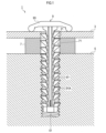
図1は、本発明の実施形態1における、取付具、電子基板、基体およびエラストマー部材の状態を示す断面模式図である。
[Embodiment 1]
FIG. 1 is a schematic cross-sectional view showing the state of a fixture, an electronic board, a base body, and an elastomer member in a first embodiment of the present invention.
図1に示すように、本実施形態の固定構造1は、電子基板3と、基体5と、エラストマー部材7と、取付具9とを備える。電子基板3は第1取付孔31を有し、基体5は第2取付孔51を有する。第2取付孔51は、その内側にめねじ構造を有する。エラストマー部材7は、電子基板3と基体5との間に配置され、第3取付孔71を有する。取付具9は、脚部91と頭部93とを有し、脚部91の軸表面には弾性ひれ91Aが形成されている。
As shown in FIG. 1, the
本発明で使用されるエラストマー部材の基材の1つとして選択されるスチレン系エラストマーは、例えば、ポリスチレン-ポリ(エチレン-エチレン/プロピレン)ブロック-ポリスチレンブロックコポリマー(SEEPS)、ポリスチレン-ポリ(エチレン/プロピレン)-ポリスチレンブロックコポリマー(SEPS)、ポリスチレン-ポリ(エチレン/プロピレン)-ポリスチレンブロックコポリマー(SEBS)、ポリスチレン-ポリブタジエンブロックコポリマー(SBC)、ポリスチレン-ポリイソプレン-ポリスチレンブロックコポリマー(SIS)等が挙げられる。これらは単独で又は2種以上を組み合わせて使用されても良い。 Examples of styrene-based elastomers selected as one of the substrates of the elastomer member used in the present invention include polystyrene-poly(ethylene-ethylene/propylene) block-polystyrene block copolymer (SEEPS), polystyrene-poly(ethylene/propylene)-polystyrene block copolymer (SEPS), polystyrene-poly(ethylene/propylene)-polystyrene block copolymer (SEBS), polystyrene-polybutadiene block copolymer (SBC), polystyrene-polyisoprene-polystyrene block copolymer (SIS), etc. These may be used alone or in combination of two or more.
上市されているスチレン系エラストマー(例えば、SEEPS)としては、商品名「セプトン4055」(株式会社クラレ製)、商品名「セプトン4077」(株式会社クラレ製)、商品名「セプトン4099」(株式会社クラレ製)等が挙げられる。 Examples of styrene-based elastomers (e.g., SEEPS) on the market include products under the trade names "Septon 4055" (manufactured by Kuraray Co., Ltd.), "Septon 4077" (manufactured by Kuraray Co., Ltd.), and "Septon 4099" (manufactured by Kuraray Co., Ltd.).
本発明で使用されるエラストマー部材の基材の1つとして選択されるアクリル系エラストマーは、1種又は2種以上の(メタ)アクリレートを重合してなるアクリル系重合体と、1種又は2種以上の(メタ)アクリレートとを少なくとも含む組成物である。(メタ)アクリレートは、例えば、エチル(メタ)アクリレート、n-プロピル(メタ)アクリレート、i-プロピル(メタ)アクリレート、n-ブチル(メタ)アクリレート、i-ブチル(メタ)アクリレート、n-ペンチル(メタ)アクリレート、i-ペンチル(メタ)アクリレート、2-エチルヘキシル(メタ)アクリレート、n-ヘキシル(メタ)アクリレート、n-オクチル(メタ)アクリレート、i-オクチル(メタ)アクリレート、n-ノニル(メタ)アクリレート、i-ノニル(メタ)アクリレート、i-デシル(メタ)アクリレート、ラウリル(メタ)アクリレート、トリデシル(メタ)アクリレート、i-ミリスチル(メタ)アクリレート、ステアリル(メタ)アクリレート、i-ステアリル(メタ)アクリレート等が挙げられる。アクリル系エラストマーは、アクリル系重合体と共に、モノマーとしての(メタ)アクリレートも含んでいる。また、モノマーとしての(メタ)アクリレートを単独で又は2種類以上を組み合わせて使用されても良い。 The acrylic elastomer selected as one of the base materials for the elastomer member used in the present invention is a composition containing at least an acrylic polymer obtained by polymerizing one or more (meth)acrylates, and one or more (meth)acrylates. Examples of the (meth)acrylate include ethyl (meth)acrylate, n-propyl (meth)acrylate, i-propyl (meth)acrylate, n-butyl (meth)acrylate, i-butyl (meth)acrylate, n-pentyl (meth)acrylate, i-pentyl (meth)acrylate, 2-ethylhexyl (meth)acrylate, n-hexyl (meth)acrylate, n-octyl (meth)acrylate, i-octyl (meth)acrylate, n-nonyl (meth)acrylate, i-nonyl (meth)acrylate, i-decyl (meth)acrylate, lauryl (meth)acrylate, tridecyl (meth)acrylate, i-myristyl (meth)acrylate, stearyl (meth)acrylate, i-stearyl (meth)acrylate, etc. The acrylic elastomer contains (meth)acrylate as a monomer together with the acrylic polymer. In addition, (meth)acrylates as monomers may be used alone or in combination of two or more types.
上市されているアクリル系エラストマーとしては、商品名「アクリキュアー(登録商標)」(株式会社日本触媒製;HD-Aシリーズ)等が挙げられる。
本発明で使用されるパラフィン系プロセスオイルは、エラストマー部材を構成する主材料の1つであり、エラストマー部材に柔軟性等を付与する。パラフィン系プロセスオイルとしては、例えば、動粘度(40℃)が300~400mm2/sのものが使用される。
Examples of acrylic elastomers on the market include the product name "Acrycure (registered trademark)" (manufactured by Nippon Shokubai Co., Ltd.; HD-A series).
The paraffin-based process oil used in the present invention is one of the main materials constituting the elastomer member, and imparts flexibility to the elastomer member, etc. As the paraffin-based process oil, for example, one having a kinetic viscosity (40° C.) of 300 to 400 mm 2 /s is used.
本発明で使用されるオレフィン系樹脂は、エチレン、プロピレン、ブテン等のオレフィン類の単独重合体もしくは共重合体、又はこれらのオレフィン類と共重合可能な単量体成分との共重合体からなる。具体的には、ポリエチレン、ポリプロピレン、エチレン-酢酸ビニル共重合体、エチレン-アクリル酸エチル共重合体、エチレン-アクリル酸共重合体、エチレン-メタクリル酸メチル共重合体、エチレン-α-オレフィン共重合体、エチレン-プロピレン共重合体、エチレン-ブテン共重合体等が挙げられる。これらは単独で又は2種以上を組み合わせて使用されても良い。 The olefin resin used in the present invention is composed of a homopolymer or copolymer of olefins such as ethylene, propylene, butene, or a copolymer of these olefins and a monomer component copolymerizable therewith. Specific examples include polyethylene, polypropylene, ethylene-vinyl acetate copolymer, ethylene-ethyl acrylate copolymer, ethylene-acrylic acid copolymer, ethylene-methyl methacrylate copolymer, ethylene-α-olefin copolymer, ethylene-propylene copolymer, ethylene-butene copolymer, etc. These may be used alone or in combination of two or more.
本発明で使用されるオレフィン系樹脂は、エラストマー部材100質量部に対して、9~13質量部の割合で配合される。オレフィン系樹脂の配合量が多すぎると、混錬性(離型性)等が失われる虞がある。また、オレフィン系樹脂の配合量が少なすぎると、耐熱性等の特性が失われる虞がある。 The olefin resin used in the present invention is blended in a ratio of 9 to 13 parts by mass per 100 parts by mass of the elastomer member. If the blended amount of olefin resin is too high, there is a risk of losing properties such as mixability (mold releasability). Also, if the blended amount of olefin resin is too low, there is a risk of losing properties such as heat resistance.
本発明で使用される架橋剤は、有機過酸化物からなり、所定の温度以上に加熱されるとラジカルを発生してエラストマー同士を部分的に架橋させるものである。架橋剤としては、例えば、1,1-ビス(t-ブチルパーオキシ)-3,5,5-トリメチルシクロヘキサン、2,5-ジメチルヘキサン-2,5-ジヒドロパーオキサイド、ジ-t-ブチルパーオキサイド、t-ブチルクミルパーオキサイド、ジクミルパーオキサイド、α,α-ビス(t-ブチルパーオキシ)-p-ジイソプロピルベンゼン、2,5-ジメチル-2,5-ジ(t-ブチルパーオキシ)ヘキサン、2,5-ジメチル-2,5-ジ(t-ブチルパーオキシ)-ヘキシン-3、ベンゾイルパーオキサイド、t-ブチルパーオキシベンゼン、t-ブチルパーオキシマレイン酸、t-ブチルパーオキシイソプロピルカーボネート、t-ブチルパーオキシベンゾエイト等が挙げられる。これらは単独で又は2種以上を組み合わせて使用されても良い。 The crosslinking agent used in the present invention is made of an organic peroxide, which generates radicals when heated to a predetermined temperature or higher, thereby partially crosslinking the elastomers. Examples of crosslinking agents include 1,1-bis(t-butylperoxy)-3,5,5-trimethylcyclohexane, 2,5-dimethylhexane-2,5-dihydroperoxide, di-t-butyl peroxide, t-butylcumyl peroxide, dicumyl peroxide, α,α-bis(t-butylperoxy)-p-diisopropylbenzene, 2,5-dimethyl-2,5-di(t-butylperoxy)hexane, 2,5-dimethyl-2,5-di(t-butylperoxy)-hexyne-3, benzoyl peroxide, t-butylperoxybenzene, t-butylperoxymaleic acid, t-butylperoxyisopropylcarbonate, and t-butylperoxybenzoate. These may be used alone or in combination of two or more.
架橋剤は、エラストマー部材100質量部に対して、5~7質量部の割合で配合される。架橋剤の配合量が多すぎると、エラストマー部材が硬くなりすぎて成形することができない虞がある。また、架橋剤の配合量が少なすぎると、耐熱性等の特性が失われる虞がある。 The cross-linking agent is mixed in a ratio of 5 to 7 parts by mass per 100 parts by mass of the elastomer member. If too much cross-linking agent is mixed, the elastomer member may become too hard and may not be able to be molded. If too little cross-linking agent is mixed, properties such as heat resistance may be lost.
本発明で使用される架橋助剤は、架橋剤と併用され、エラストマー部材同士の架橋を促す等の機能を備える。架橋助剤としては、例えば、トリアリルシアヌレート、トリメタリルイソシアヌレート、トリアクリルホルマール、トリアリルトリメリテート、N,N‘-m-フェニレンビスマレイミド、ジプロパギルテレフタレート、ジアリルフタレート、テトラアリルテレフタレートアミド、トリアリルホスフェート、ビスマレイミド、フッ素化トリアリルイソシアヌレート(1,3,5-トリス(2,3,3-トリフルオロ-2-プロペニル)-1,3,5-トリアジン-2,4,6-トリオン)、トリス(ジアリルアミン)-S-トリアジン、亜リン酸トリアリル、N,N-ジアリルアクリルアミド、1,6-ジビニルドデカフルオロヘキサン、ヘキサアリルホスホルアミド、N,N,N’,N’-テトラアリルフタルアミド、N,N,N’,N’-テトラアリルマロンアミド、トリビニルイソシアヌレート、2,4,6-トリビニルメチルトリシロキサン、トリ(5-ノルボルネン-2-メチレン)シアヌレート、トリアリルホスファイト等が挙げられる。これらは単独で又は2種以上を組み合わせて使用されても良い。 The crosslinking aid used in the present invention is used in combination with a crosslinking agent and has the function of promoting crosslinking between elastomer members. Examples of crosslinking aids include triallyl cyanurate, trimethallyl isocyanurate, triacrylformal, triallyl trimellitate, N,N'-m-phenylene bismaleimide, dipropargyl terephthalate, diallyl phthalate, tetraallyl terephthalate amide, triallyl phosphate, bismaleimide, fluorinated triallyl isocyanurate (1,3,5-tris(2,3,3-trifluoro-2-propenyl)-1,3,5-triazine-2,4,6- trione), tris(diallylamine)-S-triazine, triallyl phosphite, N,N-diallylacrylamide, 1,6-divinyldodecafluorohexane, hexaallyl phosphoramide, N,N,N',N'-tetraallylphthalamide, N,N,N',N'-tetraallylmalonamide, trivinyl isocyanurate, 2,4,6-trivinylmethyltrisiloxane, tri(5-norbornene-2-methylene) cyanurate, triallyl phosphite, etc. These may be used alone or in combination of two or more.
架橋助剤は、エラストマー部材100質量部に対して、13~15質量部の割合で配合される。架橋助剤の配合量が多すぎると、成形性等が損なわれる虞がある。また、架橋助剤の配合量が少なすぎると、耐熱性等の特性が損なわれる虞がある。 The cross-linking aid is mixed in a ratio of 13 to 15 parts by mass per 100 parts by mass of the elastomer member. If the amount of cross-linking aid mixed is too high, moldability and other properties may be impaired. If the amount of cross-linking aid mixed is too low, properties such as heat resistance may be impaired.
本発明で使用される酸化防止剤は、架橋剤等と併用され、エラストマー部材の酸化を抑制する機能を備える。また、酸化防止剤は、エラストマー部材の架橋量を調節等の機能を備える。酸化防止剤としては、例えば、構造中にフェノール系水酸基を含有するフェノール系酸化防止剤を使用することができ、特にヒンダードフェノール系酸化防止剤が好ましい。 The antioxidant used in the present invention is used in combination with a crosslinking agent or the like and has the function of suppressing oxidation of the elastomer member. The antioxidant also has the function of adjusting the amount of crosslinking of the elastomer member. As the antioxidant, for example, a phenol-based antioxidant containing a phenol-based hydroxyl group in the structure can be used, and a hindered phenol-based antioxidant is particularly preferred.
酸化防止剤は、エラストマー部材100質量部に対して、3~4質量部の割合で配合される。酸化防止剤の配合量が多すぎると、エラストマー部材の架橋が十分に形成されず、耐熱性等が損なわれる虞がある。また、酸化防止剤の配合量が少なすぎると、エラストマー部材にオイルブリード等の不具合が発生する虞がある。 The antioxidant is mixed in a ratio of 3 to 4 parts by mass per 100 parts by mass of the elastomer component. If the amount of antioxidant mixed is too high, the crosslinking of the elastomer component may not be sufficiently formed, and heat resistance, etc. may be impaired. If the amount of antioxidant mixed is too low, there is a risk of problems such as oil bleeding occurring in the elastomer component.
本発明で使用される水酸化マグネシウムは、高級脂肪酸で表面処理(コーティング処理)されたものからなる。水酸化マグネシウムをコーティングしている高級脂肪酸としては、パルミチン酸、ステアリン酸、オレイン酸、リノール酸等が挙げられる。また、水酸化マグネシウムの粒径については、レーザー回折法等で求められる中央値(D50)で0.5~1.5μmが好ましい。 The magnesium hydroxide used in the present invention is surface-treated (coated) with a higher fatty acid. Examples of higher fatty acids that coat the magnesium hydroxide include palmitic acid, stearic acid, oleic acid, and linoleic acid. The particle size of the magnesium hydroxide is preferably 0.5 to 1.5 μm in terms of the median (D50) determined by a laser diffraction method or the like.
水酸化マグネシウムは、エラストマー部材100質量部に対して、15~25質量部の割合で配合される。水酸化マグネシウムの配合量が多すぎると、エラストマー部材の圧縮永久歪値が高くなり、硬度も高くなってしまう。また、水酸化マグネシウムの配合量が少なすぎると、エラストマー部材にオイルブリード等の不具合が発生する虞がある。 Magnesium hydroxide is mixed in a ratio of 15 to 25 parts by mass per 100 parts by mass of the elastomer member. If the amount of magnesium hydroxide mixed is too high, the compression set value of the elastomer member will be high, and the hardness will also be high. If the amount of magnesium hydroxide mixed is too low, there is a risk of problems such as oil bleeding occurring in the elastomer member.
エラストマー部材は、本発明の目的を損なわない限り、他の成分が配合されていても良い。他の成分として、例えば、着色剤(顔料、染料)、カーボンブラック、導電性フィラー、紫外線吸収剤、難燃剤、可塑剤、防腐剤、溶剤等が挙げられる。 The elastomer member may contain other components as long as they do not impair the objective of the present invention. Examples of other components include colorants (pigments, dyes), carbon black, conductive fillers, UV absorbers, flame retardants, plasticizers, preservatives, solvents, etc.
本発明で使用されるエラストマー部材のJIS A硬度は、スチレン系エラストマーを基材とした場合は0~37、アクリル系エラストマーを基材とした場合は32~64の範囲にあることが好ましい。JIS A硬度がこのような値であると、エラストマー部材は変形して取付具の脚部の隙間に入り込みやすく、より好適な防振効果を得ることができる。 The JIS A hardness of the elastomer member used in the present invention is preferably in the range of 0 to 37 when the base material is a styrene-based elastomer, and 32 to 64 when the base material is an acrylic elastomer. If the JIS A hardness is within these ranges, the elastomer member will easily deform and enter the gaps in the legs of the mounting fixture, providing a more suitable vibration-damping effect.
[JIS A硬度の測定]
本発明で使用されるエラストマー部材について、JIS A硬度を測定するために、シート状の試験サンプルを用意した。その試験サンプルに対し、23±3℃の条件下で、アスカーゴム硬度計A型(高分子計器株式会社製)を用いて、JIS K 6253-3に準拠したJIS A硬度の測定を行った。
[Measurement of JIS A hardness]
For the elastomer member used in the present invention, a sheet-shaped test sample was prepared in order to measure the JIS A hardness. The test sample was subjected to measurement of the JIS A hardness in accordance with JIS K 6253-3 using an Asker Rubber Hardness Tester Type A (manufactured by Kobunshi Keiki Co., Ltd.) under the condition of 23±3° C.
図2Aおよび図2Bは、各部の寸法名称を示す概念図である。
本発明においては、図2Aに示すように、めねじ構造の狭くなっている径を「内径」とし、広くなっている径を「谷の径」と規定する。また、図2Bに示すように、取付具9の脚部91の径を「外径」と規定する。
2A and 2B are conceptual diagrams showing the names of dimensions of each part.
In the present invention, as shown in Fig. 2A, the narrower diameter of the female thread structure is defined as the "inner diameter" and the wider diameter is defined as the "root diameter." Also, as shown in Fig. 2B, the diameter of the
取付具9の脚部91を第2取付孔51に圧入および固定する際には、弾性ひれ91Aが機能する。圧入前の脚部91の外径は、第2取付孔51よりも大きくなっているが、脚部91を第2取付孔51に押し込むことで、弾性ひれ91Aが弾性変形し、脚部91の外径が圧入可能になるまで縮小する。また、脚部91が第2取付孔51に圧入された後には、弾性変形していた弾性ひれ91Aが元の形状に復元しようとする。その形状復元により、弾性ひれ91Aが第2取付孔51の内壁に加圧接触して引っかかるため、脚部91は第2取付孔51に固定される。
The
[引張圧縮試験]
取付具9の脚部91が電子基板3の第1取付孔31を貫通し、第2取付孔51に圧入および固定された本発明の実施形態1の固定構造1に対し、引張圧縮試験機(ミネベアミツミ株式会社製;TCM-50)を用いて、圧入および固定された取付具9の頭部93を引っ張り、脚部91を第2取付孔51から抜き取ることができる力(離脱力)を測定した。なお、測定時の条件は、室温25℃、湿度45%RH、引張速度10mm/minであった。
[Tension and compression test]
For the fixing
引張圧縮試験の結果、取付具9は458~541Nの力で頭部93を引っ張ることにより、脚部91を第2取付孔51から完全に抜き取ることができた。なお、取付具9の替わりとして、従来の金属製の取付具を用いた固定構造に対しても同様の試験を行ったが、458~541Nの力では、金属製の取付具の脚部を第2取付孔51から抜き取ることはできなかった。すなわち、取付具9は金属製の取付具よりも弱い力で固定されていることがわかった。
As a result of the tension and compression test, the
[振動試験(防振効果の測定)]
取付具9の防振効果は、全自動振動試験機(エミック株式会社製;F-300BM/A)を用いて測定した。より具体的には、基体5を全自動振動試験機の加振装置とし、電子基板3を加振装置に取り付ける取付板とし、加振装置に対して取付板を取付具9により固定した。取付板の加振装置とは反対側の面上には加速度計が設置され、加振装置により加えられた振動が、周波数に対して取付板にどれだけ伝達するかという振動伝達係数を測定することができる。なお、取付板は600gの物を使用した。
[Vibration test (measurement of vibration-proofing effect)]
The vibration isolation effect of the
振動伝達係数とは、加振装置により加えられる振動を1としたとき、取付板に伝達する振動の比を表したものである。振動伝達係数が1を超える場合は、加振装置により加えられた振動が増幅されて取付板に伝達されることを示す。逆に、振動伝達係数が1未満である場合は、伝達途中でエネルギー損失が起こり、加振装置により加えられた振動が抑制されて取付板に伝達されることを示す。 The vibration transmission coefficient represents the ratio of the vibration transmitted to the mounting plate when the vibration applied by the vibration device is set to 1. When the vibration transmission coefficient exceeds 1, it indicates that the vibration applied by the vibration device is amplified and transmitted to the mounting plate. Conversely, when the vibration transmission coefficient is less than 1, it indicates that energy loss occurs during transmission, and the vibration applied by the vibration device is suppressed and transmitted to the mounting plate.
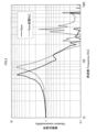
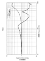
図3は、本発明の実施形態1と、実施形態1の取付具を従来の金属製の取付具(金属ねじ)にした場合との振動試験の結果を比較したグラフである。
図3に示す振動試験は、電子基板3と基体5とに挟まれるエラストマー部材7の厚さを5mmにして行った。図3に示すように、実施形態1は、従来の金属ねじを用いた場合と比較して、共振周波数(振動伝達率が1を大きく超えるピークの周波数)が低周波側にシフトすることがわかった。
FIG. 3 is a graph comparing the results of a vibration test between the first embodiment of the present invention and a case in which the fastener of the first embodiment is replaced with a conventional metal fastener (metal screw).
The vibration test shown in Fig. 3 was carried out with the thickness of the
振動対策が必要となる周波数帯域は電子機器やその使用状況によって様々だが、その周波数帯域において、電子機器に与えられた衝撃や振動のエネルギーが増幅することは避ける必要がある。その点で、図3に示すように、従来の金属ねじを用いた場合は約300~400Hzの周波数帯域で発生するピークの振動伝達係数が1以上となり、加えられた振動エネルギーが増幅してしまうことがわかる。それに対し、固定構造1では、約90Hz以上の周波数帯域において、特定周波数帯域でのエネルギーの増幅もなく、振動伝達係数を1以下に抑制できるため、幅広い周波数帯域の様々な電子機器に対して安定的な防振効果を得ることができる。なお、取付板の質量を変更して測定した結果、2kg以下の取付板であれば所期の防振効果を得ることができた。
The frequency bands where vibration countermeasures are necessary vary depending on the electronic device and its usage, but it is necessary to avoid amplifying the energy of shocks and vibrations given to the electronic device in those frequency bands. In that regard, as shown in Figure 3, when a conventional metal screw is used, the vibration transmission coefficient of the peak that occurs in the frequency band of approximately 300 to 400 Hz is 1 or more, and it can be seen that the applied vibration energy is amplified. In contrast, with fixed
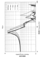
図4は、本発明の実施形態1における、エラストマー部材の厚みを変えた振動試験結果を比較したグラフである。
図4に示すように、電子基板3と基体5との間に配置されるエラストマー部材7は、厚いほど防振効果は高くなる傾向があるとわかった。
FIG. 4 is a graph comparing vibration test results when the thickness of the elastomer member is changed in the first embodiment of the present invention.
As shown in FIG. 4, it has been found that the thicker the
実施形態1では、エラストマー部材の厚みを5mmにした場合までしか実験を行っていないが、図4で示されるように、ある程度までエラストマー部材が分厚いほど良好な防振効果が得られると予想できる。ただし、例えばエラストマー部材の厚みが4mmの場合と、エラストマー部材の厚みが5mmの場合とを比較しても、それらの防振効果には大きな違いは見られない。そのため、エラストマー部材は無制限に分厚ければ良いというわけではなく、本発明の固定構造では、エラストマー部材の厚みが8mm程度まで、より好ましくは6mmまでであれば、良好な防振効果を得ることができると予想される。 In the first embodiment, experiments were only conducted with an elastomer member thickness of 5 mm, but as shown in Figure 4, it is expected that the thicker the elastomer member is, the better the vibration-damping effect will be. However, for example, when comparing an elastomer member thickness of 4 mm with an elastomer member thickness of 5 mm, no significant difference in vibration-damping effect is observed. Therefore, it is not the case that the elastomer member can be made as thick as possible, and it is expected that with the fixing structure of the present invention, a good vibration-damping effect can be obtained if the elastomer member is made up of a thickness of up to about 8 mm, more preferably up to 6 mm.
[実施形態2]
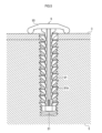
図5は、本発明の実施形態2における、取付具、電子基板および基体の状態を示す断面模式図である。
[Embodiment 2]
FIG. 5 is a schematic cross-sectional view showing the state of a fixture, an electronic board, and a base body in the second embodiment of the present invention.
図5は、電子基板3と基体5との間にエラストマー部材を配置せず、電子基板3と基体5とが接した状態の固定構造を示している。図5に示す実施形態2は、エラストマー部材7が配置されていないことだけが実施形態1と異なる。
Figure 5 shows a fixing structure in which the
図6は、本発明の実施形態2と、実施形態2の取付具を金属製の取付具(金属ねじ)にした場合との振動試験結果を比較したグラフである。
図6は、本発明の固定構造においては、実施形態1よりは防振効果(振動伝達係数の値)が小さいものの、エラストマー部材を配置せず、取付具9だけを使用した固定構造であっても、防振効果は得られることを示す。
FIG. 6 is a graph comparing vibration test results between the second embodiment of the present invention and the second embodiment in which the fastener is made of metal (metal screws).
FIG. 6 shows that, although the vibration-damping effect (value of vibration transmission coefficient) is smaller in the fixing structure of the present invention than in the first embodiment, even in a fixing structure using only mounting
本発明の実施形態1および2は、金属ねじを用いた固定構造と比較すると、取付具9の脚部91と第2取付孔51の内壁との間の間隙が大きく存在している。また、本発明の実施形態1および2においては、脚部91の各弾性はね91Aの先端が第2取付孔51の内壁と接していると考えられる。そのため、取付具9に対して衝撃や振動が加わった際には、前記弾性はね91Aの先端と第2取付孔51の内壁とが擦れ、主にはその摩擦力により防振効果が得られていると考えられる。本発明の固定構造は、金属ねじを用いた固定構造と比較して、摩擦力が大きくなりやすい構造であるため、より高い防振効果が得られると考えられる。
Compared to a fixing structure using metal screws, in the first and second embodiments of the present invention, there is a larger gap between the
エラストマー部材7は、そのJIS A硬度が、スチレン系エラストマーを基材とした場合は0~37、アクリル系エラストマーを基材とした場合は32~64であり、柔軟性の高い物質である。そのため、取付具9の脚部91が第3取付孔71を貫通する際には、前記脚部91が有する複数の弾性ひれ91Aの間に存在する隙間に対し、前記エラストマー部材7の一端が変形して入り込むと考えられる。このような構造の場合、衝撃や振動が伝達される部材に対して前記エラストマー部材7の接触面積が増加するため、より好適な防振効果を得ることができる。
The
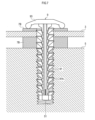
図7は、本発明の変形例1における、取付具、電子基板、基体およびエラストマー部材の状態を示す断面模式図である。
図7は、エラストマー部材を電子基板3と基体5との間に配置するだけでなく、取付具9の頭部93と電子基板3との間にも配置した状態の固定構造を示す。図7の電子基板3よりも上側に配置されるエラストマー部材を上部エラストマー7A、下側に配置されるエラストマー部材を下部エラストマー7Bとして、電子基板3に対し、上下面からの防振効果を期待することができる。また上部エラストマー7Aの厚さと、下部エラストマー7Bの厚さとを適宜調整することにより、より様々な周波数帯域での防振効果を期待することができる。
FIG. 7 is a schematic cross-sectional view showing the state of a fixture, an electronic board, a base body, and an elastomer member in the first modified example of the present invention.
Fig. 7 shows a fixing structure in which an elastomer member is disposed not only between the
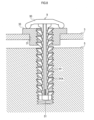
図8は、本発明の変形例2における取付具、電子基板および固定部材の状態を示す断面模式図である。
図8は、電子基板3に設けられる第1取付孔31に、めねじ構造をもつ金属カラー33が埋め込まれた状態での固定構造を示す。図8に示す構造の場合、取付具9は、第2取付孔51に加え、第1取付孔31に埋め込まれた金属カラー33のめねじ構造でも脚部91が固定される。そのため、取付具9により、エラストマー部材7を配置しない場合でも、電子基板3と基体5とを接しさせることなく固定することが可能になる。
FIG. 8 is a schematic cross-sectional view showing the state of a fixture, an electronic board, and a fixing member in the second modified example of the present invention.
Fig. 8 shows a fixing structure in which a
以上では、本発明の好適な実施形態について説明したが、本発明は上記の実施形態に限定されるものではなく、本発明の概念及び特許請求の範囲に含まれるあらゆる態様を含む。また、上述した課題および効果の少なくとも一部を奏するように、各構成を適宜選択的に組み合わせても良い。また、例えば、上記実施形態における各構成要素の形状、材料、配置、寸法などは、本発明の具体的な使用態様によって適宜変更され得る。 Although the preferred embodiment of the present invention has been described above, the present invention is not limited to the above embodiment, and includes all aspects included in the concept of the present invention and the scope of the claims. In addition, each configuration may be appropriately and selectively combined so as to achieve at least some of the above-mentioned problems and effects. In addition, for example, the shape, material, arrangement, dimensions, etc. of each component in the above embodiment may be appropriately changed depending on the specific usage mode of the present invention.
1…固定構造、3…電子基板、5…基体、7…エラストマー部材、7A…上部エラストマー、7B…下部エラストマー、9…取付具、31…第1取付孔、33…金属カラー、51…第2取付孔、71…第3取付孔、91…脚部、91A…弾性ひれ、93…頭部。 1...fixing structure, 3...electronic board, 5...base, 7...elastomeric member, 7A...upper elastomer, 7B...lower elastomer, 9...mounting fixture, 31...first mounting hole, 33...metal collar, 51...second mounting hole, 71...third mounting hole, 91...leg, 91A...elastic fin, 93...head.
Claims (4)
内側にめねじ構造を有する少なくとも1つ以上の第2取付孔が設けられた基体と、
前記電子基板を前記基体に固定するための樹脂製の取付具と
を備え、
前記取付具は、
少なくとも第1取付孔の内径よりも大きな外径を有する頭部と、
前記頭部から一方向に延設されて前記第2取付孔に圧入可能な軸状の脚部と
を有し、
前記脚部には軸表面を起点とした延設方向と前記脚部の圧入方向とのなす角が鈍角となる複数の弾性ひれが形成され、
前記脚部は、前記弾性ひれが弾性変形することにより前記第2取付孔に圧入することができ、前記弾性変形の復元で前記弾性ひれが前記めねじ構造に引っかかることにより前記第2取付孔に固定することができ、
前記頭部は、前記第1取付孔から離れた位置で前記電子基板に接触しており、
前記頭部は、前記電子基板と前記頭部との接触箇所と、前記第1取付孔と、の間では、前記電子基板に接触しておらず、
前記電子基板と前記基体との間に配置され、前記脚部が貫通可能な第3取付孔を有するエラストマー部材を備えており、
前記複数の弾性ひれのうち、一部の前記弾性ひれは前記エラストマー部材の内周側に配置されており、その一部の前記弾性ひれの先端が前記エラストマー部材に接触しており、
前記頭部を550Nの力で引っ張ることで、固定されている前記脚部を前記第2取付孔から離脱可能に構成される固定構造。 an electronic substrate having at least one first mounting hole;
a base body provided with at least one second mounting hole having an internal thread structure;
a resin mounting fixture for fixing the electronic board to the base,
The mounting fixture includes:
a head portion having an outer diameter greater than an inner diameter of at least the first mounting hole;
a shaft-shaped leg portion extending in one direction from the head portion and capable of being press-fitted into the second mounting hole;
A plurality of elastic fins are formed on the leg portion such that an angle between an extension direction starting from a shaft surface and a press-fit direction of the leg portion is an obtuse angle,
The leg portion can be press-fitted into the second mounting hole by the elastic fin being elastically deformed, and the elastic fin can be fixed to the second mounting hole by being caught in the female thread structure by the restoration of the elastic deformation,
the head is in contact with the electronic board at a position away from the first mounting hole,
the head does not contact the electronic board between a contact point between the electronic board and the head and the first mounting hole,
an elastomer member disposed between the electronic board and the base and having a third mounting hole through which the leg can pass;
Among the plurality of elastic fins, some of the elastic fins are disposed on the inner circumferential side of the elastomer member, and tips of some of the elastic fins are in contact with the elastomer member,
A fixing structure configured so that the fixed leg portion can be detached from the second mounting hole by pulling the head portion with a force of 550 N.
前記第3取付孔の直径は、3~9mmであり、
前記エラストマー部材の外径は、5~20mmであり、
前記エラストマー部材の円筒軸方向の厚みは、1~6mmである請求項1に記載の固定構造。 the elastomeric member has a cylindrical shape;
The diameter of the third mounting hole is 3 to 9 mm.
The outer diameter of the elastomeric member is 5 to 20 mm;
2. The fixing structure according to claim 1 , wherein the thickness of the elastomer member in the cylindrical axial direction is 1 to 6 mm.
前記エラストマー部材は、スチレン系エラストマーまたはアクリル系エラストマーと、パラフィン系プロセスオイルと、オレフィン系樹脂と、有機過酸化物からなる架橋剤と、架橋助剤と、酸化防止剤と、高級脂肪酸で表面処理された水酸化マグネシウムとを備え、
前記スチレン系エラストマーまたはアクリル系エラストマー100質量部に対し、
前記パラフィン系プロセスオイル400~485質量部と、
前記オレフィン系樹脂9~13質量部と
前記架橋剤5~7質量部と、
前記架橋助剤13~16.9質量部と、
前記酸化防止剤3~4質量部と、
前記水酸化マグネシウム15~25質量部とをそれぞれ配合し、
前記エラストマー部材のJIS A硬度が、スチレン系エラストマーを配合した場合は0~37であり、アクリル系エラストマーを配合した場合は32~64である請求項1又は請求項2に記載の固定構造。 The mounting tool is made of polyamide resin,
the elastomer member comprises a styrene-based elastomer or an acrylic-based elastomer, a paraffin-based process oil, an olefin-based resin, a cross-linking agent made of an organic peroxide, a cross-linking assistant, an antioxidant, and magnesium hydroxide surface-treated with a higher fatty acid;
Relative to 100 parts by mass of the styrene-based elastomer or acrylic-based elastomer,
400 to 485 parts by mass of the paraffinic process oil;
9 to 13 parts by mass of the olefin-based resin; 5 to 7 parts by mass of the crosslinking agent;
13 to 16.9 parts by mass of the crosslinking assistant;
3 to 4 parts by mass of the antioxidant;
and 15 to 25 parts by mass of the magnesium hydroxide,
3. The fixing structure according to claim 1 , wherein the elastomeric member has a JIS A hardness of 0 to 37 when a styrene-based elastomer is blended therein, and a JIS A hardness of 32 to 64 when an acrylic-based elastomer is blended therein.
Priority Applications (1)
| Application Number | Priority Date | Filing Date | Title |
|---|---|---|---|
| JP2021185163A JP7621650B2 (en) | 2021-11-12 | 2021-11-12 | Fixed Structure |
Applications Claiming Priority (1)
| Application Number | Priority Date | Filing Date | Title |
|---|---|---|---|
| JP2021185163A JP7621650B2 (en) | 2021-11-12 | 2021-11-12 | Fixed Structure |
Publications (2)
| Publication Number | Publication Date |
|---|---|
| JP2023072541A JP2023072541A (en) | 2023-05-24 |
| JP7621650B2 true JP7621650B2 (en) | 2025-01-27 |
Family
ID=86424298
Family Applications (1)
| Application Number | Title | Priority Date | Filing Date |
|---|---|---|---|
| JP2021185163A Active JP7621650B2 (en) | 2021-11-12 | 2021-11-12 | Fixed Structure |
Country Status (1)
| Country | Link |
|---|---|
| JP (1) | JP7621650B2 (en) |
Citations (4)
| Publication number | Priority date | Publication date | Assignee | Title |
|---|---|---|---|---|
| JP2005530648A (en) | 2002-06-25 | 2005-10-13 | ツェットエフ レムフェルダー メタルヴァーレン アクチエンゲゼルシャフト | Pendulum support made of extruded body |
| JP2006342862A (en) | 2005-06-08 | 2006-12-21 | Daiwa Kasei Ind Co Ltd | Screw member |
| JP2009156303A (en) | 2007-12-25 | 2009-07-16 | Nippon Pop Rivets & Fasteners Ltd | Clip repeatedly and easily attached/detached to/from member having female screw formed thereon |
| JP2018012785A (en) | 2016-07-21 | 2018-01-25 | 北川工業株式会社 | Composition, heat-resistant vibration-proof material manufacturing method and heat-resistant vibration-proof material |
-
2021
- 2021-11-12 JP JP2021185163A patent/JP7621650B2/en active Active
Patent Citations (4)
| Publication number | Priority date | Publication date | Assignee | Title |
|---|---|---|---|---|
| JP2005530648A (en) | 2002-06-25 | 2005-10-13 | ツェットエフ レムフェルダー メタルヴァーレン アクチエンゲゼルシャフト | Pendulum support made of extruded body |
| JP2006342862A (en) | 2005-06-08 | 2006-12-21 | Daiwa Kasei Ind Co Ltd | Screw member |
| JP2009156303A (en) | 2007-12-25 | 2009-07-16 | Nippon Pop Rivets & Fasteners Ltd | Clip repeatedly and easily attached/detached to/from member having female screw formed thereon |
| JP2018012785A (en) | 2016-07-21 | 2018-01-25 | 北川工業株式会社 | Composition, heat-resistant vibration-proof material manufacturing method and heat-resistant vibration-proof material |
Also Published As
| Publication number | Publication date |
|---|---|
| JP2023072541A (en) | 2023-05-24 |
Similar Documents
| Publication | Publication Date | Title |
|---|---|---|
| JP6883973B2 (en) | Adhesive tape | |
| CN103459532B (en) | Flame-retardant heat-conductive adhesive sheet | |
| JP7621650B2 (en) | Fixed Structure | |
| CN102947932A (en) | Heat conduction sheet, method for manufacturing heat conduction sheet, and heat dissipation device | |
| JP2013147541A (en) | Polymer for adhesive, adhesive composition and heat-peelable adhesive sheet | |
| JP6045929B2 (en) | Flame retardant thermal conductive adhesive sheet | |
| US20040087721A1 (en) | Noise and vibration damping materials | |
| JPWO2019159340A1 (en) | Heat conductive sheet and heat dissipation device using heat conductive sheet | |
| JP2020196828A (en) | Adhesive heat radiation sheet | |
| JP5672201B2 (en) | Anisotropic conductive film and method for manufacturing connection structure | |
| TW202113014A (en) | Adhesive tape | |
| JP6783980B2 (en) | Composition for heat and vibration isolator, manufacturing method of heat and vibration isolator and heat and vibration isolator | |
| WO2007057318A1 (en) | Process for temporary fixing of a polymeric layer material on rough surfaces | |
| US20170321049A1 (en) | Thermally conductive material | |
| WO2008140080A1 (en) | Electron source | |
| JP7236466B2 (en) | Foam adhesive tape for flexible display and flexible display laminate | |
| JP2019214674A (en) | Acrylic rubber composition | |
| JP7099704B2 (en) | Thermal conductive material | |
| CN104011156A (en) | Thermoconductive adhesive sheet | |
| JP6060453B2 (en) | Damping material | |
| JP2018016766A (en) | Acrylic rubber composition and elastic member | |
| JP4503579B2 (en) | Damping material | |
| JP7340455B2 (en) | Rubber composition containing ethylene-propylene-nonconjugated polyene copolymer | |
| JP6365934B2 (en) | Damping material | |
| JP2012017467A (en) | Water dispersion type adhesive composition and adhesive sheet |
Legal Events
| Date | Code | Title | Description |
|---|---|---|---|
| A621 | Written request for application examination |
Free format text: JAPANESE INTERMEDIATE CODE: A621 Effective date: 20240208 |
|
| A977 | Report on retrieval |
Free format text: JAPANESE INTERMEDIATE CODE: A971007 Effective date: 20240830 |
|
| A131 | Notification of reasons for refusal |
Free format text: JAPANESE INTERMEDIATE CODE: A131 Effective date: 20240910 |
|
| A521 | Request for written amendment filed |
Free format text: JAPANESE INTERMEDIATE CODE: A523 Effective date: 20241111 |
|
| TRDD | Decision of grant or rejection written | ||
| A01 | Written decision to grant a patent or to grant a registration (utility model) |
Free format text: JAPANESE INTERMEDIATE CODE: A01 Effective date: 20241224 |
|
| A61 | First payment of annual fees (during grant procedure) |
Free format text: JAPANESE INTERMEDIATE CODE: A61 Effective date: 20250107 |
|
| R150 | Certificate of patent or registration of utility model |
Ref document number: 7621650 Country of ref document: JP Free format text: JAPANESE INTERMEDIATE CODE: R150 |