JP7621649B2 - Heat exchanger and cooling system using same - Google Patents
Heat exchanger and cooling system using same Download PDFInfo
- Publication number
- JP7621649B2 JP7621649B2 JP2021169052A JP2021169052A JP7621649B2 JP 7621649 B2 JP7621649 B2 JP 7621649B2 JP 2021169052 A JP2021169052 A JP 2021169052A JP 2021169052 A JP2021169052 A JP 2021169052A JP 7621649 B2 JP7621649 B2 JP 7621649B2
- Authority
- JP
- Japan
- Prior art keywords
- plate
- hole
- circular hole
- heat exchanger
- space
- Prior art date
- Legal status (The legal status is an assumption and is not a legal conclusion. Google has not performed a legal analysis and makes no representation as to the accuracy of the status listed.)
- Active
Links
- 238000001816 cooling Methods 0.000 title claims description 35
- 239000000758 substrate Substances 0.000 claims description 46
- 239000012530 fluid Substances 0.000 claims description 15
- 238000005057 refrigeration Methods 0.000 claims description 5
- 238000000465 moulding Methods 0.000 claims description 2
- 239000003507 refrigerant Substances 0.000 description 91
- 239000000498 cooling water Substances 0.000 description 73
- XLYOFNOQVPJJNP-UHFFFAOYSA-N water Substances O XLYOFNOQVPJJNP-UHFFFAOYSA-N 0.000 description 15
- 238000005219 brazing Methods 0.000 description 9
- 238000000034 method Methods 0.000 description 5
- 238000003825 pressing Methods 0.000 description 5
- 238000010586 diagram Methods 0.000 description 4
- 239000000463 material Substances 0.000 description 4
- 238000004891 communication Methods 0.000 description 3
- 238000004519 manufacturing process Methods 0.000 description 3
- 229910052751 metal Inorganic materials 0.000 description 3
- 239000002184 metal Substances 0.000 description 3
- WHXSMMKQMYFTQS-UHFFFAOYSA-N Lithium Chemical compound [Li] WHXSMMKQMYFTQS-UHFFFAOYSA-N 0.000 description 2
- 229910052782 aluminium Inorganic materials 0.000 description 2
- XAGFODPZIPBFFR-UHFFFAOYSA-N aluminium Chemical compound [Al] XAGFODPZIPBFFR-UHFFFAOYSA-N 0.000 description 2
- 238000005516 engineering process Methods 0.000 description 2
- 229910052744 lithium Inorganic materials 0.000 description 2
- 239000000155 melt Substances 0.000 description 2
- 238000004088 simulation Methods 0.000 description 2
- 238000004378 air conditioning Methods 0.000 description 1
- 230000007423 decrease Effects 0.000 description 1
- 230000012447 hatching Effects 0.000 description 1
- 238000009413 insulation Methods 0.000 description 1
- 238000005304 joining Methods 0.000 description 1
- 239000007788 liquid Substances 0.000 description 1
- 230000000149 penetrating effect Effects 0.000 description 1
Images


Classifications
-
- Y—GENERAL TAGGING OF NEW TECHNOLOGICAL DEVELOPMENTS; GENERAL TAGGING OF CROSS-SECTIONAL TECHNOLOGIES SPANNING OVER SEVERAL SECTIONS OF THE IPC; TECHNICAL SUBJECTS COVERED BY FORMER USPC CROSS-REFERENCE ART COLLECTIONS [XRACs] AND DIGESTS
- Y02—TECHNOLOGIES OR APPLICATIONS FOR MITIGATION OR ADAPTATION AGAINST CLIMATE CHANGE
- Y02E—REDUCTION OF GREENHOUSE GAS [GHG] EMISSIONS, RELATED TO ENERGY GENERATION, TRANSMISSION OR DISTRIBUTION
- Y02E60/00—Enabling technologies; Technologies with a potential or indirect contribution to GHG emissions mitigation
- Y02E60/10—Energy storage using batteries
Landscapes
- Heat-Exchange Devices With Radiators And Conduit Assemblies (AREA)
Description
本発明は、熱交換器及びこれを用いた冷却システムに関する。 The present invention relates to a heat exchanger and a cooling system using the same.
近年、環境への関心の高まりから、全世界的にBEV(Buttery Electric Vehicle)、PHEV(Plug-in Hybrid Electric Vehicle)などの電気自動車(EV)の需要が徐々に増加している。それに伴い、電気自動車に搭載可能であって、繰り返し充放電可能な二次電池に関する研究が活発に行われている。 In recent years, due to growing concern about the environment, the demand for electric vehicles (EVs) such as BEVs (Battery Electric Vehicles) and PHEVs (Plug-in Hybrid Electric Vehicles) is gradually increasing worldwide. Accordingly, active research is being conducted on secondary batteries that can be installed in electric vehicles and can be repeatedly charged and discharged.
例えばリチウム電池のような二次電池は、所定温度範囲で使用することで寿命が延びることが知られているが、使用時や充電時に所定温度範囲を超えて発熱することが問題となっている。そこで、寿命を延ばすために、二次電池を冷却するシステムが必要とされる。 For example, it is known that the lifespan of secondary batteries such as lithium batteries can be extended by using them within a specified temperature range, but there is a problem with them generating heat when used or charged and exceeding the specified temperature range. Therefore, a system for cooling secondary batteries is needed to extend their lifespan.
一般的な二次電池の冷却システムとしては、大きく分けて水冷方式と空冷方式が知られている。従来、電気自動車用二次電池の冷却システムとして、空気を用いた空冷方式が採用されることが多い。空冷方式の冷却システムは、車両の外部または内部の空気を吸入して二次電池を冷却させた後、加熱された空気を車両の外部に排出するものであり、簡素な構成を特徴とする。 Generally, cooling systems for secondary batteries can be broadly divided into water-cooled and air-cooled systems. Conventionally, air-cooled systems have often been used as cooling systems for secondary batteries in electric vehicles. Air-cooled cooling systems draw in air from either the outside or inside of the vehicle to cool the secondary battery, and then expel the heated air to the outside of the vehicle, and are characterized by their simple configuration.
しかし、航続距離を確保するために、大容量の二次電池を搭載した電気自動車が増えており、それに伴い二次電池の発熱量も大幅に増加することから、空気のみを用いて二次電池を所定温度範囲に冷却する空冷方式には限界がある。特に、車両が停車している場合など、走行風を冷却に用いることができず、二次電池から発生する熱を効果的に車外へと放出して冷却することができないという問題がある。 However, to ensure driving range, an increasing number of electric vehicles are being equipped with large-capacity secondary batteries, which has resulted in a significant increase in the amount of heat generated by the secondary batteries. This means that there are limitations to the air-cooling method, which uses only air to cool the secondary battery to a specified temperature range. In particular, when the vehicle is stopped, the wind generated by the vehicle's movement cannot be used for cooling, and there is a problem in that the heat generated by the secondary battery cannot be effectively released outside the vehicle for cooling.
一方、水冷式の冷却システムは、冷却水のような熱交換媒体を用いて二次電池を冷却する技術である。水冷式の冷却システムは、空冷式に比べて冷却効率に優れ、車両停車時にも二次電池を冷却できるというメリットがある。ただし、二次電池として使用されることが多いリチウム電池は、20℃~30℃の温度範囲が好ましい使用範囲とされているのに対し、二次電池を冷却する冷却水と外気との間で熱交換を行う水冷式の冷却システムは、例えば真夏に30℃以下に水温を維持することが困難であり、したがって二次電池の冷却に用いるには不十分である。 On the other hand, a water-cooled cooling system is a technology that uses a heat exchange medium such as cooling water to cool a secondary battery. A water-cooled cooling system has the advantage of being more efficient at cooling than an air-cooled system, and can cool the secondary battery even when the vehicle is stopped. However, while the preferred temperature range for lithium batteries, which are often used as secondary batteries, is 20°C to 30°C, a water-cooled cooling system that exchanges heat between the cooling water that cools the secondary battery and the outside air has difficulty maintaining the water temperature below 30°C in midsummer, for example, and is therefore insufficient for use in cooling secondary batteries.
そこで、空調用の冷媒を使用して二次電池を冷却することが検討されている。しかし、冷媒を直接、二次電池の冷却に使用すると過冷却や絶縁不良等の不具合が生じる恐れがあるため、冷媒により冷却水を冷却し、その冷却水で二次電池を安定して冷却する間接液冷システムが開発されている。 Therefore, the use of air conditioning refrigerants to cool secondary batteries has been considered. However, using refrigerants directly to cool secondary batteries can lead to problems such as overcooling and poor insulation, so indirect liquid cooling systems have been developed that use refrigerants to cool cooling water, which then stably cools the secondary batteries.
特許文献1には、積層した金属板(プレート)の間に冷媒と冷却水とを交互に流すことで、金属板を介して冷媒と冷却水との間で熱交換を行う熱交換器(以下、積層型熱交換器という)が開示されている。
ところで、電気自動車に水冷方式の電池冷却システムを搭載することにより、乗車スペースが減少するおそれがあり、また電気自動車の車重が増大して航続距離が短くなるおそれがある。したがって、水冷方式により二次電池を冷却する冷却する電池冷却システムにおいては、その効率化や小型化が課題となる。特許文献1の積層型熱交換器は、平面視で長方形状のプレートに挟まれた層内を冷媒と冷却水が通過する構成であり、冷媒或いは冷却水はプレートに形成された2つの円形孔を通じて層と層の間を移動するが、円形孔がプレートの同じ長辺側に形成されているため、各層内において当該長辺側の流れに比べて他方の長辺側の流れが停滞し各層における流れが不均一となり、それにより熱交換効率が低いという問題がある。
これに対し、2つの円形孔を長方形プレートの対角位置に設けることにより、各層における流れの偏りが減り熱交換効率を高めることができるが、このような構造とすると製造コストが増大するという別の問題が生じる。即ち、各プレートはプレス加工によって成形されるが、対角位置に円形孔を設ける構造にあっては、必然的に隣接するプレートは異なる形状を有することになり、2種類の金属板を交互に積層する必要が生じる。従って、プレートを製造するプレス型もその種類分だけ必要となり、製造コストが増大することとなる。また、熱交換効率を高めるためには、プレートの表面構造をどのようにすべきかという問題もある。
However, by installing a water-cooled battery cooling system in an electric vehicle, the passenger space may be reduced, and the weight of the electric vehicle may increase, resulting in a shorter driving range. Therefore, in a battery cooling system that cools a secondary battery by a water-cooling method, the efficiency and size of the system are issues. The stacked heat exchanger of
On the other hand, by providing two circular holes at diagonal positions of a rectangular plate, the flow deviation in each layer can be reduced and the heat exchange efficiency can be improved, but this structure creates another problem of increased manufacturing costs. That is, each plate is formed by pressing, and in a structure with circular holes at diagonal positions, adjacent plates will inevitably have different shapes, and it becomes necessary to alternately stack two types of metal plates. Therefore, the number of press dies required to manufacture the plates is equal to the number of types, which increases the manufacturing cost. Another problem is how to structure the surface of the plate in order to increase the heat exchange efficiency.
本発明は、かかる従来技術の問題点に鑑みてなされたものであり、コンパクトでありながら、熱交換効率を高めることができる安価な熱交換器及びこれを用いた冷却システムを提供することを目的とする。 The present invention was made in consideration of the problems with the conventional technology, and aims to provide an inexpensive heat exchanger that is compact yet capable of increasing heat exchange efficiency, and a cooling system using the same.
上記目的を達成するために、本発明による熱交換器は、第1流体と第2流体との間で熱交換を行う熱交換器であって、
複数のプレートを積層したプレート積層部を有し、
前記プレートは、基板と、前記基板の周囲に形成された縁部と、前記基板に形成された少なくとも2つの孔とを有し、
重ねた2枚の前記プレートの間の空間に、一方の前記プレートの前記孔から第1流体または第2流体が供給され、他方の前記プレートの前記孔を介して排出され、
前記基板は、前記孔の中心回りに複数の同心円に沿ってそれぞれ3つ以上並べられた突起を有し、前記孔の中心に近い同心円の前記突起を内方突起とし、前記内方突起よりも前記孔の中心から離間した同心円の前記突起を外方突起としたときに、同じ同心円に沿って間隔をあけて隣接する2つの前記内方突起を、前記孔の中心から放射方向外方に投影すると、投影された前記内方突起は、同一の前記外方突起に重なり、
前記プレートは、第1の孔及び第2の孔と、前記第1の孔の周囲にて前記基板に形成された筒部とを有し、
前記第1の孔及び前記第2の孔は、前記プレートの中心に対して90度をなす角度で形成されており、
隣接する前記プレート同士は、90度の位相差をもって配置されており、一方の前記プレートの前記筒部を、他方の前記プレートの前記第2の孔の周囲に当接させて積層されており、
前記基板には、前記プレートの中心を挟んで、前記第1の孔とは反対側に第1の平面部が形成され、また前記プレートの中心を挟んで、前記第2の孔とは反対側に第2の平面部が形成されている、ことを特徴とする。
In order to achieve the above object, a heat exchanger according to the present invention is a heat exchanger for exchanging heat between a first fluid and a second fluid,
A plate stacking portion in which a plurality of plates are stacked,
The plate has a substrate, an edge formed around the periphery of the substrate, and at least two holes formed in the substrate;
A first fluid or a second fluid is supplied to a space between the two overlapping plates through the holes of one of the plates and discharged through the holes of the other plate;
the substrate has three or more protrusions arranged along a plurality of concentric circles around the center of the hole, the protrusions on the concentric circles closer to the center of the hole being inner protrusions, and the protrusions on the concentric circles farther from the center of the hole than the inner protrusions being outer protrusions, when two adjacent inner protrusions spaced apart along the same concentric circle are projected radially outward from the center of the hole, the projected inner protrusions overlap the same outer protrusion,
the plate has a first hole and a second hole, and a cylindrical portion formed in the substrate around the first hole;
the first hole and the second hole are formed at an angle of 90 degrees with respect to a center of the plate;
adjacent plates are arranged with a phase difference of 90 degrees and are stacked with the cylindrical portion of one plate abutting against a periphery of the second hole of the other plate,
The substrate is characterized in that a first planar portion is formed on the opposite side of the first hole across the center of the plate, and a second planar portion is formed on the opposite side of the second hole across the center of the plate .
本発明により、コンパクトでありながら、熱交換効率を高めることができる安価な熱交換器及びこれを用いた冷却システムを提供することができる。 The present invention provides an inexpensive heat exchanger that is compact yet capable of increasing heat exchange efficiency, and a cooling system that uses the same.
以下、図面を参照して、本発明にかかる熱交換器の実施形態について説明する。以下においては、冷媒と水との間で熱交換を行って水の冷却(ないし温度調整)を行い、この水により電池の冷却(ないし温度調整)を行う電池冷却システムに本発明の熱交換器を適用した実施形態を説明するが、本発明の熱交換器は、異なる流体間(或いは同種の流体間)で熱交換を行う用途に広く用いることができる。 Below, an embodiment of the heat exchanger according to the present invention will be described with reference to the drawings. In the following, an embodiment in which the heat exchanger of the present invention is applied to a battery cooling system in which heat is exchanged between a refrigerant and water to cool (or regulate the temperature of) the water, and the water is used to cool (or regulate the temperature of) the battery, is described. However, the heat exchanger of the present invention can be used widely for applications in which heat is exchanged between different fluids (or between fluids of the same type).
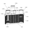
図1を参照して、本実施形態における熱交換器10について説明する。図1は、本実施形態における熱交換器10を、電池冷却システム1に適用した例を模式的に示す図である。本実施形態では、電池冷却システム1は、冷凍サイクル2と、電池冷却回路(冷却回路ともいう)3とを有する。
The
冷凍サイクル2は、コンプレッサ2aと、コンデンサ2bと、膨張弁2cと、これらを接続する冷媒配管2dとを有し、冷媒配管2d内には第1流体としての冷媒が注入されて冷凍サイクル2内を循環する。熱交換器10は、膨張弁2cと、コンプレッサ2aとの間に配置される。
The
一方、電池冷却回路3は、二次電池を収容する筐体3aと、水ポンプ3bと、これらを接続する水配管3cとを有し、水配管3c内には第2流体としての冷却水が注入されて電池冷却回路3内を循環する。熱交換器10は、水ポンプ3bと、筐体3aとの間に配置される。筐体3aは、収容された二次電池に接する壁に、水配管3cに接続されたウォータージャケットが配設され、筐体3aにおいて二次電池と冷却水との間で熱交換が行われる。
The
(第1の実施形態)
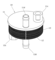
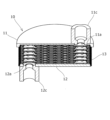
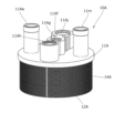
次に、熱交換器10について説明する。図2は、熱交換器10の斜視図である。図3、4は、熱交換器10を、軸線を含む異なる断面で切断して示す斜視図である。熱交換器10は、第1円盤部11と、第2円盤部12と、第1円盤部11と第2円盤部12とに挟持されるプレート積層部13とを有する。
(First embodiment)
Next, the
第1円盤部11には、第1冷媒用開口11aと、第1冷却水用開口11bとが両側面を貫通するようにして形成されている。第1冷媒用開口11aには、冷媒入口用コネクタ11cがロウ付けなどにより取り付けられており、第1冷却水用開口11bには、冷却水入口用コネクタ11dがロウ付けなどにより取り付けられている。
The
第2円盤部12には、第2冷媒用開口12aと、第2冷却水用開口12bとが両側面を貫通するようにして形成されている。第2冷媒用開口12aには、冷媒出口用コネクタ12cがロウ付けなどにより取り付けられており、第2冷却水用開口12bには、冷却水出口用コネクタ12dがロウ付けなどにより取り付けられている。冷却水入口用コネクタ11dと、冷却水出口用コネクタ12dは、水配管3cに接続され、冷媒入口用コネクタ11cと、冷媒出口用コネクタ12cは、冷媒配管2dに接続される。
The
プレート積層部13は、複数枚(ここでは22枚)のプレート13aを積層してなり、冷媒と冷却水の熱交換を行う機能を有する。
The
電池冷却システム1の動作時に、コンプレッサ2aで加圧された冷媒は、冷媒配管2dを通過し、コンデンサ2bで液化され、膨張弁2cに送られる。また、膨張弁2cで断熱膨張された冷媒は、熱交換器10に送り出され、熱交換器10にて冷却水との間で熱交換が行われる。熱交換された後の冷媒は、コンプレッサ2aへと戻されて再び加圧される。
When the
一方、熱交換器10で冷媒によって冷却された冷却水は、水ポンプ3bにより水配管3cを通して筐体3aに送られ、筐体3a内の二次電池を冷却する。二次電池からの熱で加温された冷却水は、再び熱交換器10に戻り、冷媒により冷却される。冷却水の比熱が比較的大きいことから、冷媒による過冷却が抑制され、二次電池を効率よく安定して冷却することができる。
Meanwhile, the cooling water cooled by the refrigerant in the
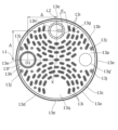
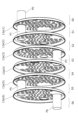
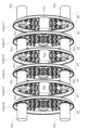
プレート積層部13の構造について説明する。図5は、プレート13aの正面図である。図6(a)は、プレート13aの一部を示す正面図であり、図6(b)は、図6(a)のプレート13aをA-A線で切断して側面視して拡大した断面図である。図7、8は、プレート積層部13の一部を分解して示す斜視図であるが、貫通路を模式化して示しており、また軸線回りの角度を変えて示している。
The structure of the
積層されるプレート13aは、例えば平板のアルミニウム材をプレス加工した成形品であって、共通の(同一の)形状を有する。図に示すように、プレート13aは、円形の基板13bと、基板13bの外周に繋がる円錐壁部(縁部)13cと、を連設してなる。円錐壁部13cの端部は、全周にわたって折り返されて折り返し部13dを形成している。折り返し部13dには、周方向に沿って90度ごとに、位置決め基準としての切欠13eが形成されている。折り返し部13dは、切欠13eにより途切れていてもよい。
The
図5において、基板13bの中心Xから、一つの切欠13eの中心に向かって直線L1を引き、また直線L1に対して直角に、中心Xから直線L2を引いたとき、直線L2は別の切欠13eの中心を通過する。
In FIG. 5, when a straight line L1 is drawn from the center X of the
ここで、中心Xから距離Δである直線L1上の位置O1を孔中心として、第1の円形孔13fが基板13bに形成され、また中心Xから同じ距離Δである直線L2上の位置O2を孔中心として、第2の円形孔13gが基板13bに形成されている。換言すれば、第1の円形孔13f及び第2の円形孔13gは、プレートの中心Xに対して90度をなす角度で形成されている。第1の円形孔13fと、第2の円形孔13gの内径は等しい。
A first circular hole 13f is formed in the
第2の円形孔13gの周囲は平坦であるが、第1の円形孔13fの周囲には、円錐壁部13cと同じ側に突出するように環状凸部(筒部)13hが形成されている。本実施形態においては、環状凸部13hは位置O1を中心とした円環形状を有しており、隣接するプレート13aに対して90度位相差を付与したときに、他方のプレート13aの第2の円形孔13gと同心円の関係になる。その際に、一方のプレート13aの環状凸部13hは、隣接するプレート13aの第2の円形孔13gを囲繞するように配置されるが、環状凸部13hにより囲繞できる面積が第2の円形孔13gの面積に比べ広い場合、必ずしも第2の円形孔13gの同心円上に配置される必要はない。
The periphery of the second
図6(a)において、第2の円形孔13gの中心O2に対して、複数本(ここでは5本)の同心円C1~C5に沿って、それぞれ3つ以上の突起13iが、間隔をあけて基板13bに配設されている。最も外側の同心円C5は、基板13bの中心Xより外側を通過しているが、中心X上、またはそれより中心O2側を通過してもよい。同心円C1~C5の径差αは、等しくてもよいし、異なっていてもよい。また同心円C1~C5の径差αは、第2の円形孔13gの内径をφとすると、α=0.3φ~0.6φであると好ましい。なお、ここで述べる値は、プレート13aを軸線方向に見たときのものとする。
In FIG. 6(a), three or
突起13iは、円錐壁部13cと同じ側に突出しており、図6(a)に示すプレート13aの軸線方向に見て略長円形状(または略長方形状)を有し、同心円の接線方向にその長手方向軸線を重ねて配置されている。また突起13iの全長βは、第2の円形孔13gの内径をφとすると、β=0.3φ~0.6φであると好ましい。また、突起13iの幅γは、第2の円形孔13gの内径をφとすると、γ=0.1φ~0.3φであると好ましい。各突起13iの長さ及び幅は等しいと好ましいが、基板13bの面方向において他の構造物との干渉を回避するときは、短くしてもよい。
The
第2の円形孔13gと、中心O2から最も近い同心円C1上の突起13iとの距離σは、第2の円形孔13gの内径をφとすると、σ=0.3φ~0.8φであると好ましい。図6(b)に示すように、基板13bから突起13iまでの高さHは、基板13bから環状凸部13hの高さhと同等あるいは低くなっており、h=0.3H~1.0Hであると好ましい。また突起13iは、幅方向中心が最も高く、両側に向かうにつれて漸次高さが低くなる形状を有していると好ましい。
The distance σ between the second
中心O2から放射方向に見て、一の同心円(例えばC1)に沿って隣接して並んだ2つの突起13i(ここでは内方突起という)の間に、その外側に配置された同心円(例えばC2)に沿って配設された突起13i(ここでは外方突起という)が位置すると好ましい。内方突起が位置する同心円と、外方突起が位置する同心円とは、隣接していなくてもよい。
When viewed in the radial direction from the center O2, it is preferable that a
より具体的には、中心O2から放射方向外方に向かって、2つの内方突起(図6(a)の13i1、13i2)を投影したときに、投影された内方突起の双方が、1つの(同一の)外方突起(図6(a)の13i3)の長手方向両端にそれぞれ重なると好ましい。図6(a)においては、2つの内方突起(13i1、13i2)の端部にそれぞれ接して中心O2から放射方向に延在する投影線PL1、PL2を示しており、投影線PL1から外方突起(13i3)の一端までの距離、及び投影線PL2から外方突起(13i3)の他端までの距離が、それぞれ重なり量となる。このような配置関係とすることにより、2つの内方突起(13i1、13i2)の間を通過した流体(冷媒あるいは冷却水)は、外側突起(13i3)によりそのまま放射方向外側に直進して流れることが阻害され円周方向両側に分岐することになる。第2の円形孔13gから流入した流体は、このような分岐を繰り返してプレート全域に偏りなく流れることとなり、熱交換効率を向上させることが出来る。なお、すくなくとも一部の突起において上記関係が成立すればよく、必ずしもすべての突起において上記関係が成立する必要はない。
More specifically, when two inner protrusions (13i1, 13i2 in FIG. 6(a)) are projected radially outward from the center O2, it is preferable that both projected inner protrusions overlap both longitudinal ends of one (same) outer protrusion (13i3 in FIG. 6(a)). FIG. 6(a) shows projection lines PL1, PL2 that extend radially from the center O2 and are tangent to the ends of the two inner protrusions (13i1, 13i2), and the distance from the projection line PL1 to one end of the outer protrusion (13i3) and the distance from the projection line PL2 to the other end of the outer protrusion (13i3) are the amounts of overlap. With this arrangement, the fluid (refrigerant or cooling water) that passes between the two inner protrusions (13i1, 13i2) is prevented from flowing straight outward in the radial direction by the outer protrusion (13i3), and is instead branched to both sides in the circumferential direction. The fluid that flows in from the second
外方突起の一方端または他端に対する投影された内方突起の重なり量は、外方突起の全長βの10%以上、30%以下であると好ましい。また、隣接する内方突起同士の間隔ωは、隣接する同心円上における内方突起と外方突起の間隔(ここでは同心円の径差α―突起の幅γ)±30%以内であると好ましい。 It is preferable that the amount of overlap of the inner protrusion projected onto one end or the other end of the outer protrusion is 10% or more and 30% or less of the total length β of the outer protrusion. In addition, it is preferable that the distance ω between adjacent inner protrusions is within ±30% of the distance between the inner protrusion and the outer protrusion on adjacent concentric circles (here, the radius difference α of the concentric circles - the width γ of the protrusion).
さらに別の突起13iが、直線L1及びその延長線を挟んで線対称に、基板13bに配置されているが、異なる形状としてもよい。
A
図5において、環状凸部13h及び円錐壁部13cの近傍において、円筒状である2つのボス13jが基板13bに形成されている。基板13bからボス13jまでの高さは、基板13bから環状凸部13hの高さに略等しい。
In FIG. 5, two
中心Xを挟んで、環状凸部13hと対称の位置における基板13bには、第1の平面部13pが形成されており、第1の平面部13pには突起が形成されていない。ただし、第1の平面部13pの近傍において、中心Xを挟んでボス13jと対称の位置に、別なボス13jが形成されている。
A first
また中心Xを挟んで、第2の円形孔13gと対称の位置における基板13bには、第2の平面部13qが形成されており、第2の平面部13qには突起が形成されていない。
A second
プレート13aは、1枚の平板をプレス成形することによって、基板13b、円錐壁部13c、折り返し部13d、切欠13e、第1の円形孔13f、第2の円形孔13g、環状凸部13h、突起13i、ボス13jを一度に形成することができる。より具体的には、プレス型の押圧により、基板13bに対して、円錐壁部13cが折り曲げられ、さらに円錐壁部13cの端部が折り返されて折り返し部13dが形成される。
The
また、プレス型の押圧により、第1の円形孔13f及び第2の円形孔13gが打ち抜かれ、環状凸部13h、突起13i、ボス13jに対応する型に押圧されて、環状凸部13h、突起13i、ボス13jが円錐壁部13cに囲われる側に突出して形成される。環状凸部13h、突起13i、ボス13jと反対側の面には、これらに対応する凹部が形成される。第1の平面部13pと第2の平面部13qは、プレス成形されることなく、原材の平板状態を維持する。
The first circular hole 13f and the second
図7、8に示すように、各プレート13aは、円錐壁部13cが同じ側(ここでは左方)を向くように積層される。円錐壁部13cの折り返し部13d側は、基板13b側よりも径が大きいため、各プレート13aの積層を容易に行うことができる。ただし、一のプレート13aに対し、隣接して重ねるプレート13aは、中心X回りに回転させて積層される。
As shown in Figures 7 and 8, the
より具体的には、図5のプレート13a(表側プレートという)に対して、その背面側に積層されるプレート(裏側プレートという)は、中心Xを基準に90度、時計回りに相対回転させて(位相差をもって)積層される。これにより、図5に点線で示す、裏側プレートの環状凸部13h’は、表側プレート13aの第2の円形孔13gの周囲における平坦な基板13bに、ハッチングで示すように全周にわたって当接する。言い換えると、裏側プレートの環状凸部13h’は、表側プレート13aの第2の円形孔13gを囲繞した状態で基板13bに当接している。一方、図5に点線で示す、裏側プレートの第2の円形孔13g’は、表側プレート13aの第1の平面部13pに対向する。
More specifically, the plate (referred to as the rear plate) stacked on the rear side of the
プレートの積層に当たり、切欠13eを整列させることで、裏側プレートの環状凸部13h’と、表側プレート13aの第2の円形孔13gとの同軸度を精度良く確保できる。この時、裏側プレートのボス13jが、第2の円形孔13gの周囲における平坦な基板13b、及び第2の平面部13qに当接することで、表側プレート13aと裏側プレートとの軸線方向の位置決めがなされ、両者が適切な間隔で保持される。
When stacking the plates, the
このように、積層順で1枚目のプレート13aに対して、2枚目のプレート13aを時計回りに90度回転させ、また2枚目のプレート13aに対して、3枚目のプレート13aを時計回りに90度回転させ、以下同様にして22枚のプレート13aが積層される。
In this way, the
プレート13aの表面には、比較的低い温度で溶けやすい素材が被覆されており、このようにして積層されたプレート13aを電気炉などに投入して加熱することで、表面の素材が溶融し、プレート13aの当接した表面同士が溶着する。溶着部が冷却して固化することで、密着したプレート13aの部位が接合される。
The surfaces of the
これにより、表側プレート13aの円錐壁部13cと、裏側プレートの円錐壁部同士が全周で接合されて、内部に閉鎖された空間が生じる(図2、3参照)。また、裏側プレートの環状凸部13h’の先端と、表側プレート13aの第2の円形孔13gの周囲とが全周で接合されて、裏側プレートの環状凸部13h’の内部と、表側プレート13aの第2の円形孔13gとが流体漏れなく連通した状態となる。ここで、上記閉鎖された空間を貫通する環状凸部13h’内を、貫通路という。一方、裏側プレートの第2の円形孔13g’は、表側プレート13aの第1の平面部13pに対向しており、すなわち表側プレート13aと裏側プレートとの間の空間に開放した状態となる。
As a result, the
このようにプレート13aを積層することで、プレート積層部13が形成される。形成されたプレート積層部13は、第1円盤部11と第2円盤部12にロウ付けなどによって接合される。このとき、第1冷媒用開口11a及び第1冷却水用開口11bが、プレート積層部13の一方の端部であるプレート13aの第1の円形孔13fと第2の円形孔13gのいずれかに接続される。また第2冷媒用開口12a及び第2冷却水用開口12bが、他方の端部であるプレート13aの第1の円形孔13fと第2の円形孔13gのいずれかに接続される。本実施形態では、プレート13aの円錐壁部13cが、第2円盤部12にロウ付けされる。これにより熱交換器10が完成する。
By stacking the
図7、8に示される6枚のプレートを区別するため、右方から左方に向かって、プレート13a(1)~プレート13a(6)と符号を付す。また、プレートが積層された状態で、隣接するプレートによって閉鎖される空間にS1~S5と符号を付す。ただし、プレート13a(1)と、その右側のプレート(不図示)とによって閉鎖される空間をS0とし、プレート13a(6)と、その左側のプレート(不図示)とによって閉鎖される空間をS6とする。
To distinguish between the six plates shown in Figures 7 and 8, they are labeled from right to left as
プレート13a(1)とプレート13a(2)との間の空間S1を、貫通路P1が貫通し、プレート13a(2)とプレート13a(3)との間の空間S2を、貫通路P2が貫通し、プレート13a(3)とプレート13a(4)との間の空間S3を、貫通路P3が貫通し、プレート13a(4)とプレート13a(5)との間の空間S4を、貫通路P4が貫通し、プレート13a(5)とプレート13a(6)との間の空間S5を、貫通路P5が貫通している。さらに、空間S0を貫通路P0が貫通し、空間S6を貫通路P6が貫通している。
Through the space S1 between
一方、空間S1は、プレート13a(2)の第1の円形孔13fと、プレート13a(1)の第2の円形孔13gとに連通している。
空間S2は、プレート13a(3)の第1の円形孔13fと、プレート13a(2)の第2の円形孔13gとに連通している。
空間S3は、プレート13a(4)の第1の円形孔13fと、プレート13a(3)の第2の円形孔13gとに連通している。
空間S4は、プレート13a(5)の第1の円形孔13fと、プレート13a(4)の第2の円形孔13gとに連通している。
空間S5は、プレート13a(6)の第1の円形孔13fと、プレート13a(5)の第2の円形孔13gとに連通している。
On the other hand, the space S1 communicates with the first circular hole 13f of the
The space S2 communicates with the first circular hole 13f of the
The space S3 communicates with the first circular hole 13f of the
The space S4 communicates with the first circular hole 13f of the
The space S5 communicates with the first circular hole 13f of the
すなわち、空間S0、貫通路P1、空間S2、貫通路P3、空間S4、貫通路P5、空間S6は、相互に連通して流路を形成していることとなり(図7参照)、また、空間S1、貫通路P2、空間S3、貫通路P4、空間S5、貫通路P6は、相互に連通して流路を形成していることとなり(図8参照)、また、これら流路は相互に独立している。 In other words, space S0, through passage P1, space S2, through passage P3, space S4, through passage P5, and space S6 are interconnected to form a flow path (see FIG. 7), and space S1, through passage P2, space S3, through passage P4, space S5, and through passage P6 are interconnected to form a flow path (see FIG. 8), and these flow paths are independent of each other.
ここで、第1冷却水用開口11bを介して、空間S0に冷却水が注入されているものとする。かかる場合、冷却水は、図7に図示する白抜き円筒で示すように、空間S0から貫通路P1を介して空間S1を通過することなく、空間S2に進入する。また、冷却水は、空間S2から貫通路P3を介して空間S3を通過することなく、空間S4に進入する。さらに、冷却水は、空間S4から貫通路P5を介して空間S5を通過することなく、空間S6に進入する。その後、冷却水は、空間S6に接続された第2冷却水用開口12bから排出される。
Here, it is assumed that cooling water is injected into space S0 through the first
一方、第1冷媒用開口11a及び貫通路P0を介して、空間S0を通過することなく、空間S1に冷媒が注入されているものとする。かかる場合、冷媒は、図8に図示する白抜き円筒で示すように、空間S1から貫通路P2を介して空間S2を通過することなく、空間S3に進入する。また、冷媒は、空間S3から貫通路P4を介して空間S4を通過することなく、空間S5に進入する。さらに、冷媒は、空間S5から貫通路P6を介して空間S6を通過することなく、第2冷媒用開口12aから排出される。このように、各空間を冷媒及び冷却水が直列に通過する方式を、1パス方式という。
On the other hand, the refrigerant is injected into space S1 through the first
空間S0、空間S2、空間S4、空間S6を通過する冷却水は、これらの空間に交互に隣接する空間S1、空間S3、空間S5に注入される冷媒に対して、薄肉のプレート13aを隔てて接しており、しかも複数の突起13iを設けることで、伝熱面積を増大させるとともに、それぞれの空間を流れる冷却水と冷媒の流れに抵抗を与えて、熱交換効率を高めることができる。特に、図5に示すように、表側プレート13aの第1の円形孔13fと、裏側プレートの第2の円形孔13g’が中心Xを挟んで反対側に位置しているため、また第2の円形孔13gの中心O2から見て、内方突起の間に外方突起が位置するように配置されているため、基板13bのほぼ全面にわたって冷却水及び冷媒が流れるようになり、さらに熱交換率が高くなる。これにより、小型でありながら、熱交換効率の高い熱交換器10を実現できる。なお、プレート積層部13の軸線に沿った冷媒と冷却水の流れ方向を、相互に対向する方向としてもよい。
The cooling water passing through the spaces S0, S2, S4, and S6 is in contact with the refrigerant injected into the spaces S1, S3, and S5 alternately adjacent to these spaces, separated by the
また本実施形態によれば、同一形状のプレート13aを相対回転させて積層するのみで、熱交換器10を形成することができるため、各プレート13aを共通のプレス型により製造することができ、部品コストを大幅に低減できる。さらに、プレート13aを円形とすることで、閉鎖空間における冷媒及び冷却水の流れを均一化することができ、安定した熱交換を確保できる。
In addition, according to this embodiment, the
(第2の実施形態)
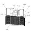
次に、第2の実施形態にかかる熱交換器10Aについて説明する。本実施形態にかかる熱交換器10Aも、図1に示す電池冷却システム1に適用することができるが、膨張弁を内蔵可能である。図9は、熱交換器10Aの斜視図である。図10、11は、熱交換器10Aを、軸線を含む異なる断面で切断して示す斜視図である。熱交換器10Aは、第1円盤部11Aと、第2円盤部12Aと、第1円盤部11Aと第2円盤部12Aとに挟持されるプレート積層部14Aとを有する。
Second Embodiment
Next, a
第1円盤部11Aには、冷媒用入口開口11Aaと、冷媒用出口開口11Acと、冷却水用入口開口11Abと、冷却水用出口開口11Adとが両側面を貫通するようにして形成されている。冷却水用入口開口11Abには、冷却水入口用コネクタ11Aeがロウ付けなどにより取り付けられており、冷却水用出口開口11Adには、冷却水出口用コネクタ11Amがロウ付けなどにより取り付けられている。
The
さらに第1円盤部11Aには、冷媒用入口開口11Aaと冷媒用出口開口11Acとを覆うようにして、流路ブロック11Afがロウ付けなどにより取り付けられている。流路ブロック11Afは、冷媒配管2dに接続される冷媒用入口コネクタ部11Agと、膨張弁2c(図1)を取り付け可能であって冷媒用入口開口11Aaに連通する膨張弁取付部11Ahと、冷媒用入口コネクタ部11Agと膨張弁取付部11Ahとを連結する連通路11Ai(図1に示す冷媒配管2dの一部を構成)と、冷媒用出口開口11Acに連通し冷媒配管2dに接続される冷媒用出口コネクタ部11Ajとを有する。
Furthermore, the flow path block 11Af is attached to the
第2円盤部12Aは、平坦な円盤状である。プレート積層部14Aは、複数枚(ここでは31枚)のプレート14Aaを積層してなり、冷媒と冷却水の熱交換を行う機能を有する。
The
図1を参照して、電池冷却システム1の動作時に、コンプレッサ2aで加圧された冷媒は、冷媒配管2dを通過し、コンデンサ2bで液化され、流路ブロック11Afの冷媒用入口コネクタ部11Agから、連通路11Aiを介して膨張弁取付部11Ahに進入する。ここで、膨張弁2cにより断熱膨張された冷媒は、冷媒用入口開口11Aaからパイプ11Akを介してプレート積層部14Aの中間部に送り出され、冷却水との間で熱交換される。熱交換された冷媒は、冷媒用出口開口11Acを介してコンプレッサ2aへと戻されて加圧される。なお、膨張弁2cにより断熱膨張された冷媒は、冷媒用入口開口11Aaからプレート積層部14Aの端部に供給されてもよい。
Referring to FIG. 1, during operation of the
熱交換器10Aで冷媒によって冷却された冷却水は、上記と同様に、水ポンプ3bにより水配管3cを通して筐体3aに送られ、筐体3a内の二次電池を冷却する。二次電池からの熱で加温された冷却水は、再び熱交換器10Aに戻り、冷媒により冷却される。以上のサイクルを繰り返すことで、二次電池を効率よく安定して冷却することができる。
The cooling water cooled by the refrigerant in the
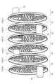
プレート積層部14Aの構造について説明する。図12は、プレート14Aaの正面図である。図13は、プレート積層部14Aの一部を分解して示す斜視図であるが、貫通路を模式化して示している。積層されるプレート14Aaは、例えばアルミニウム製であって、共通の形状を有する。図に示すように、プレート14Aaは、円形の基板14Abと、基板14Abの外周に繋がる円錐壁部(縁部)14Acと、を連設してなる。円錐壁部14Acの端部は、全周にわたって折り返されて折り返し部14Adを形成している。折り返し部14Adには、周方向に沿って90度ごとに、位置決め用の切欠14Aeが形成されている。
The structure of the
図12において、基板14Abの中心Xを通り、対向する切欠14Aeの中心に向かって直線L1を引き、また直線L1に対して直角に、中心Xから直線L2を引いたとき、直線L2は別の切欠14Aeの中心を通過する。 In FIG. 12, when a straight line L1 is drawn through the center X of the substrate 14Ab toward the center of the opposing notch 14Ae, and a straight line L2 is drawn from the center X perpendicular to the line L1, the line L2 passes through the center of another notch 14Ae.
ここで、中心Xから距離Δである直線L1上の位置O1を孔中心として、第1の円形孔14Afが基板14Abに形成され、また同じ直線L1上で中心Xから距離Δである反対側の位置O3を孔中心として、第3の円形孔14Asが基板14Abに形成されている。また中心Xから同じ距離Δである直線L2上の位置O2を孔中心として、第2の円形孔14Agが基板14Abに形成され、また同じ直線L1上の位置O4を孔中心として、第4の円形孔14Atが基板14Abに形成されている。第1の円形孔14Afと第3の円形孔14Asの内径kは等しく、第2の円形孔14Agと第4の円形孔14Atの内径Kは等しい。ここで、K≦kであり、好ましくはK=0.6k~1.0kである。 Here, a first circular hole 14Af is formed in the substrate 14Ab with the hole center at position O1 on a straight line L1 that is a distance Δ from the center X, and a third circular hole 14As is formed in the substrate 14Ab with the hole center at position O3 on the opposite side of the straight line L1 that is a distance Δ from the center X. A second circular hole 14Ag is formed in the substrate 14Ab with the hole center at position O2 on a straight line L2 that is the same distance Δ from the center X, and a fourth circular hole 14At is formed in the substrate 14Ab with the hole center at position O4 on the straight line L1. The inner diameters k of the first circular hole 14Af and the third circular hole 14As are equal, and the inner diameters K of the second circular hole 14Ag and the fourth circular hole 14At are equal. Here, K≦k, and preferably K=0.6k to 1.0k.
第2の円形孔14Ag及び第4の円形孔14Atの周囲は平坦であるが、第1の円形孔14Afの周囲には、円錐壁部14Acと同じ側に突出するように環状凸部(筒部)14Ahが形成され、また第3の円形孔14Asの周囲には、円錐壁部14Acと同じ側に突出するように環状凸部(筒部)14Auが形成されている。 The second circular hole 14Ag and the fourth circular hole 14At are flat, but the first circular hole 14Af is surrounded by an annular protrusion (tubular portion) 14Ah that protrudes on the same side as the conical wall portion 14Ac, and the third circular hole 14As is surrounded by an annular protrusion (tubular portion) 14Au that protrudes on the same side as the conical wall portion 14Ac.
本実施の形態においても、複数の突起14Aiが、第2の円形孔14Agの中心O2及び第4の円形孔14Atの中心O4に対して、複数本(ここでは5本)の同心円に沿って基板14Abに配設され、またボス14Ajが第1の円形孔14Afの中心O2及び第4の円形孔14Atの近傍に配置されている。突起14Ai及びボス14Ajの形状および配置については、上述した実施形態の突起13i及びボス13jと同様であるため、重複説明を省略する。
In this embodiment, multiple protrusions 14Ai are also arranged on the substrate 14Ab along multiple (here, five) concentric circles with respect to the center O2 of the second circular hole 14Ag and the center O4 of the fourth circular hole 14At, and bosses 14Aj are arranged near the center O2 of the first circular hole 14Af and the fourth circular hole 14At. The shapes and arrangement of the protrusions 14Ai and bosses 14Aj are similar to those of the
本実施形態のプレート14Aaも、1枚の平板をプレス成形することによって形成できる。 The plate 14Aa in this embodiment can also be formed by press molding a single flat plate.
図13に示すように、各プレート14Aaは、円錐壁部14Acが同じ側(ここでは左方)を向くように積層される。円錐壁部14Acの折り返し部14Ad側は、基板14Ab側よりも径が大きいため、各プレート14Aaの積層を容易に行うことができる。ただし、一のプレート14Aaに対し、隣接して重ねるプレート14Aaは、中心X回りに回転させて積層される。 As shown in FIG. 13, the plates 14Aa are stacked so that the conical wall portions 14Ac face the same side (left in this example). The folded portion 14Ad side of the conical wall portion 14Ac has a larger diameter than the substrate 14Ab side, so that the plates 14Aa can be stacked easily. However, the adjacent plate 14Aa is stacked by rotating it around the center X with respect to one plate 14Aa.
より具体的には、図13のプレート14Aa(表側プレートという)に対して、その背面側に積層されるプレート(裏側プレートという)は、中心Xを基準に90度、時計回りに相対回転させて(位相差をもって)積層される。これにより、裏側プレート14Aaの円形孔14Af、14Ag、14As、14Atが、中心X回りに90度回転移動し、軸線方向に見て表側プレート14Aaの円形孔に対して一つ分ずれるようにして重なる。 More specifically, the plate (referred to as the back plate) stacked on the back side of plate 14Aa (referred to as the front plate) in Fig. 13 is stacked by rotating it 90 degrees clockwise relative to center X (with a phase difference). As a result, circular holes 14Af, 14Ag, 14As, and 14At of back plate 14Aa rotate 90 degrees around center X and overlap with one circular hole of front plate 14Aa when viewed in the axial direction.
このとき、裏側プレート14Aaの環状凸部14Ah、14Auは、表側プレート14Aaの第2の円形孔14Ag及び第4の円形孔14Atの周囲における平坦な基板14Abに、全周にわたって当接し、表側プレート14Aの第2の円形孔14Ag及び第4の円形孔14Atを囲繞する。一方、裏側プレート14Aaの第2の円形孔14Ag及び第4の円形孔14Atは、表側プレート14Aaの2つの環状凸部14Ah、14Auの裏面側に対向する。すなわち、裏側プレートの環状凸部14Ah、14Auの先端側は、第2の円形孔14Ag及び第4の円形孔14Atの周囲に当接し、表側プレートの環状凸部14Ah、14Auの裏面側(先端とは反対側)では、対向する表側プレートの第2の円形孔14Ag及び第4の円形孔14Atとの間に、隙間が生じることとなる。
At this time, the annular protrusions 14Ah and 14Au of the back plate 14Aa abut the flat substrate 14Ab around the second circular hole 14Ag and the fourth circular hole 14At of the front plate 14Aa over the entire circumference, surrounding the second circular hole 14Ag and the fourth circular hole 14At of the
積層順で1枚目のプレート14Aaに対して、2枚目のプレート14Aaを時計回りに90度回転させ、また2枚目のプレート14Aaに対して、3枚目のプレート14Aaを時計回りに90度回転させ、以下同様にして31枚のプレート14Aaが積層される。 In the stacking order, the second plate 14Aa is rotated 90 degrees clockwise relative to the first plate 14Aa, and the third plate 14Aa is rotated 90 degrees clockwise relative to the second plate 14Aa, and so on until 31 plates 14Aa are stacked.
このようにプレート14Aaを積層することで、プレート積層部14Aが形成される。形成されたプレート積層部14Aは、第1円盤部11Aと第2円盤部12Aとにロウ付けなどによって接合される。本実施形態では、最終のプレート14Aaの円錐壁部14Acが、第2円盤部12Aにロウ付けされる。
By stacking the plates 14Aa in this manner, the
図13において、6枚のプレートを区別するため、右方から左方に向かって、プレート14Aa(1)~プレート14Aa(6)と符号を付す。また、プレートが積層された状態で、隣接するプレートによって閉鎖される空間にS1~S5と符号を付す。ただし、プレート14Aa(1)と、その右側のプレート(不図示)とによって閉鎖される空間をS0とし、プレート14Aa(6)と、その左側のプレート(不図示)とによって閉鎖される空間をS6とする。 In FIG. 13, to distinguish between the six plates, they are labeled from right to left as plates 14Aa(1) through 14Aa(6). In addition, when the plates are stacked, the spaces closed by adjacent plates are labeled S1 through S5. However, the space closed by plate 14Aa(1) and the plate to its right (not shown) is labeled S0, and the space closed by plate 14Aa(6) and the plate to its left (not shown) is labeled S6.
さらに、空間S0において、第2の円形孔14Ag及び第4の円形孔14Atの周囲に当接する2つの環状凸部14Ah、14Auの内部を、それぞれ貫通路P01、P02とする。また、空間S1において、第2の円形孔14Ag及び第4の円形孔14Atの周囲に当接する2つの環状凸部14Ah、14Auの内部を、それぞれ貫通路P11、P12とする。 Furthermore, in the space S0, the interiors of the two annular protrusions 14Ah and 14Au that abut against the periphery of the second circular hole 14Ag and the fourth circular hole 14At are defined as through passages P01 and P02, respectively. In addition, in the space S1, the interiors of the two annular protrusions 14Ah and 14Au that abut against the periphery of the second circular hole 14Ag and the fourth circular hole 14At are defined as through passages P11 and P12, respectively.
さらに、空間S2において、第2の円形孔14Ag及び第4の円形孔14Atの周囲に当接する2つの環状凸部14Ah、14Auの内部を、それぞれ貫通路P21、P22とする。また、空間S3において、第2の円形孔14Ag及び第4の円形孔14Atの周囲に当接する2つの環状凸部14Ah、14Auの内部を、それぞれ貫通路P31、P32とする。 Furthermore, in the space S2, the interiors of the two annular protrusions 14Ah and 14Au that abut against the periphery of the second circular hole 14Ag and the fourth circular hole 14At are defined as through passages P21 and P22, respectively. Furthermore, in the space S3, the interiors of the two annular protrusions 14Ah and 14Au that abut against the periphery of the second circular hole 14Ag and the fourth circular hole 14At are defined as through passages P31 and P32, respectively.
さらに、空間S4において、第2の円形孔14Ag及び第4の円形孔14Atの周囲に当接する2つの環状凸部14Ah、14Auの内部を、それぞれ貫通路P41、P42とする。また、空間S5において、第2の円形孔14Ag及び第4の円形孔14Atの周囲に当接する2つの環状凸部14Ah、14Auの内部を、それぞれ貫通路P51、P52とする。 Furthermore, in the space S4, the interiors of the two annular protrusions 14Ah and 14Au that abut against the periphery of the second circular hole 14Ag and the fourth circular hole 14At are defined as through passages P41 and P42, respectively. In the space S5, the interiors of the two annular protrusions 14Ah and 14Au that abut against the periphery of the second circular hole 14Ag and the fourth circular hole 14At are defined as through passages P51 and P52, respectively.
さらに、空間S6において、第2の円形孔14Ag及び第4の円形孔14Atの周囲に当接する2つの環状凸部14Ah、14Auの内部を、それぞれ貫通路P61、P62とする。 Furthermore, in the space S6, the interiors of the two annular protrusions 14Ah and 14Au that abut the periphery of the second circular hole 14Ag and the fourth circular hole 14At are defined as through passages P61 and P62, respectively.
プレート14Aa(1)とプレート14Aa(2)との間の空間S1を、貫通路P11、P12が貫通し、プレート14Aa(2)とプレート14Aa(3)との間の空間S2を、貫通路P21、P22が貫通し、プレート14Aa(3)とプレート14Aa(4)との間の空間S3を、貫通路P31、P32が貫通し、プレート14Aa(4)とプレート14Aa(5)との間の空間S4を、貫通路P41、P42が貫通し、プレート14Aa(5)とプレート14Aa(6)との間の空間S5を、貫通路P51、P52が貫通している。さらに、空間S0を貫通路P01、P02が貫通し、空間S6を貫通路P61、P62が貫通している。 Through the space S1 between plates 14Aa(1) and 14Aa(2), through passages P11 and P12, through passages P21 and P22, through space S2 between plates 14Aa(2) and 14Aa(3), through passages P31 and P32, through space S3 between plates 14Aa(3) and 14Aa(4), through passages P41 and P42, through space S4 between plates 14Aa(4) and 14Aa(5), and through passages P51 and P52, through space S5 between plates 14Aa(5) and 14Aa(6). Furthermore, through passages P01 and P02, through space S0, and through passages P61 and P62, through space S6.
一方、空間S1は、プレート14Aa(2)の第1の円形孔14Af及び第3の円形孔14Asと、プレート14Aa(1)の第2の円形孔14Ag及び第4の円形孔14Atとに連通している。
空間S2は、プレート14Aa(3)の第1の円形孔14Af及び第3の円形孔14Asと、プレート14Aa(2)の第2の円形孔14Ag及び第4の円形孔14Atとに連通している。
空間S3は、プレート14Aa(4)の第1の円形孔14Af及び第3の円形孔14Asと、プレート14Aa(3)の第2の円形孔14Ag及び第4の円形孔14Atとに連通している。
On the other hand, the space S1 communicates with the first circular hole 14Af and the third circular hole 14As of the plate 14Aa(2) and with the second circular hole 14Ag and the fourth circular hole 14At of the plate 14Aa(1).
The space S2 communicates with the first circular hole 14Af and the third circular hole 14As of the plate 14Aa(3) and with the second circular hole 14Ag and the fourth circular hole 14At of the plate 14Aa(2).
The space S3 communicates with the first circular hole 14Af and the third circular hole 14As of the plate 14Aa(4) and with the second circular hole 14Ag and the fourth circular hole 14At of the plate 14Aa(3).
空間S4は、プレート14Aa(5)の第1の円形孔14Af及び第3の円形孔14Asと、プレート14Aa(4)の第2の円形孔14Ag及び第4の円形孔14Atとに連通している。
空間S5は、プレート14Aa(6)の第1の円形孔14Af及び第3の円形孔14Asと、プレート14Aa(5)の第2の円形孔14Ag及び第4の円形孔14Atとに連通している。
The space S4 communicates with the first circular hole 14Af and the third circular hole 14As of the plate 14Aa(5) and with the second circular hole 14Ag and the fourth circular hole 14At of the plate 14Aa(4).
The space S5 communicates with the first circular hole 14Af and the third circular hole 14As of the plate 14Aa(6) and with the second circular hole 14Ag and the fourth circular hole 14At of the plate 14Aa(5).
本実施形態では、空間S0、貫通路P11、P12、空間S2、貫通路P31、P32、空間S4、貫通路P51、P52、空間S6は、相互に連通していることとなり、また、空間S1、貫通路P21、P22、空間S3、貫通路P41、P42、空間S5、貫通路P61、P62は、相互に連通していることとなり、また、これらは相互に独立した流路を形成している。 In this embodiment, space S0, through passages P11, P12, space S2, through passages P31, P32, space S4, through passages P51, P52, and space S6 are interconnected, and space S1, through passages P21, P22, space S3, through passages P41, P42, space S5, and through passages P61, P62 are interconnected, and form flow paths that are independent of each other.
ここで、冷却水用入口開口11Abを介して注入された冷却水が、貫通路P01を介して空間S1に進入しているものとする。かかる場合、矢印に示すように、冷却水の一部は、貫通路P21に向かい、残りは空間S1を通過して、貫通路P02側へと向かい、貫通路P22を介して戻ってきた冷却水と合流して、貫通路P02を通過して冷却水用出口開口11Adから排出される。 Here, it is assumed that the cooling water injected through the cooling water inlet opening 11Ab enters the space S1 through the through passage P01. In this case, as shown by the arrows, part of the cooling water flows toward the through passage P21, while the rest passes through the space S1 and flows toward the through passage P02, where it merges with the cooling water that has returned through the through passage P22, passes through the through passage P02, and is discharged from the cooling water outlet opening 11Ad.
また、貫通路P21を介して空間S3に進入した冷却水の一部は、矢印に示すように、貫通路P41に向かい、残りは空間S3を通過して、貫通路P22側へと向かい、貫通路P42を介して戻ってきた冷却水と合流して、貫通路P22を介して空間S1に向かう。 In addition, part of the cooling water that enters space S3 through passage P21 heads toward passage P41 as shown by the arrow, while the remainder passes through space S3 and heads toward passage P22, where it merges with the cooling water that has returned through passage P42 and heads toward space S1 through passage P22.
また、貫通路P41を介して空間S5に進入した冷却水の一部は、矢印に示すように、貫通路P61に向かい、残りは空間S5を通過して、貫通路P42側へと向かい、貫通路P62を介して戻ってきた冷却水と合流して、貫通路P42を介して空間S3に向かう。 In addition, part of the cooling water that enters space S5 through passage P41 heads toward passage P61 as shown by the arrow, while the remainder passes through space S5 and heads toward passage P42, where it merges with the cooling water that has returned through passage P62 and heads toward space S3 through passage P42.
これに対し、冷媒用入口開口11Aa及びパイプ11Akを介して空間S0に注入された冷媒は、冷却水と同様に、貫通路P11を介して空間S2に進入し、ここで冷媒の一部は、貫通路P31に向かい、残りは空間S2を通過して、貫通路P12側へと向かい、貫通路P32を介して戻ってきた冷媒と合流して、貫通路P12を通過して、空間S0を介して冷媒用出口開口11Acから排出される。 In contrast, the refrigerant injected into space S0 through the refrigerant inlet opening 11Aa and pipe 11Ak enters space S2 through the through passage P11, just like cooling water, where part of the refrigerant flows toward the through passage P31, while the rest passes through space S2 and flows toward the through passage P12, where it merges with the refrigerant that has returned through the through passage P32, passes through the through passage P12, and is discharged from the refrigerant outlet opening 11Ac through space S0.
また、貫通路P31を介して空間S4に進入した冷媒の一部は、貫通路P51に向かい、残りは空間S4を通過して、貫通路P32側へと向かい、貫通路P52を介して戻ってきた冷媒と合流して、貫通路P32を介して空間S2に向かう。 In addition, part of the refrigerant that entered space S4 through passage P31 heads toward passage P51, while the remainder passes through space S4 and heads toward passage P32, where it merges with the refrigerant that returned through passage P52 and heads toward space S2 through passage P32.
また、貫通路P51を介して空間S6に進入した冷媒の一部は、不図示の貫通路に向かい、残りは空間S6を通過して、貫通路P52側へと向かい、不図示の貫通路を介して戻ってきた冷媒と合流して、貫通路P52を介して空間S4に向かう。 In addition, part of the refrigerant that enters space S6 through passage P51 heads toward a passage not shown, while the remainder passes through space S6 and heads toward passage P52, where it merges with the refrigerant that has returned through the passage not shown, and heads toward space S4 through passage P52.
本実施の形態では、貫通路P01、P21、P41、P61が、冷却水の供給路となり、貫通路P02、P22、P42、P62が、冷却水の排出路となっている。また、貫通路P11、P31、P51が、冷媒の供給路となり、貫通路P12、P32、P52が、冷媒の排出路となっている。このように、各空間を冷媒及び冷却水が並列に通過する方式を、全パス方式という。 In this embodiment, through passages P01, P21, P41, and P61 serve as supply passages for cooling water, and through passages P02, P22, P42, and P62 serve as discharge passages for cooling water. In addition, through passages P11, P31, and P51 serve as supply passages for the refrigerant, and through passages P12, P32, and P52 serve as discharge passages for the refrigerant. This method in which the refrigerant and cooling water pass through each space in parallel is called the all-pass method.
本実施形態においても、空間S1、空間S3、空間S5を通過する冷却水は、これらの空間に交互に隣接する空間S0、空間S2、空間S4、空間S6に注入される冷媒に対して、薄肉のプレート14Aaを隔てて接しており、しかも複数の突起14Aiを設けることで、伝熱面積を増大させるとともに、それぞれの空間を流れる冷却水と冷媒の流れに抵抗を与えて、熱交換効率を高めることができる。特に、図12に示すように、第2の円形孔14Agと、第4の円形孔14Atが中心Xを挟んで対称に位置しているため、基板14Abのほぼ全面にわたって冷却水及び冷媒が流れるようになり、さらに熱交換率が高くなる。これにより、小型でありながら、熱交換効率の高い熱交換器10Aを実現できる。
In this embodiment, the cooling water passing through space S1, space S3, and space S5 contacts the refrigerant injected into the spaces S0, S2, S4, and S6 that are alternately adjacent to these spaces, separated by the thin plate 14Aa, and by providing multiple protrusions 14Ai, the heat transfer area is increased and resistance is applied to the flow of the cooling water and refrigerant flowing through each space, thereby improving the heat exchange efficiency. In particular, as shown in FIG. 12, the second circular hole 14Ag and the fourth circular hole 14At are located symmetrically with respect to the center X, so that the cooling water and refrigerant flow over almost the entire surface of the substrate 14Ab, further increasing the heat exchange rate. This allows a small-
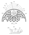
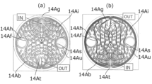
図14は、第2の実施形態に熱交換器10Aのプレート14aに対して、冷媒または冷却水を供給した場合において、基板14Ab上を流れる冷媒または冷却水の経路をシミュレーションで示した図である。図14(a)は、第2の円形孔14Agから第4の円形孔14Atへと冷媒または冷却水が流れる状態を示し、図14(b)は、第4の円形孔14Atから第2の円形孔14Agへと冷媒または冷却水が流れる状態を示している。
Figure 14 is a diagram showing a simulation of the path of the refrigerant or cooling water flowing on the substrate 14Ab when the refrigerant or cooling water is supplied to the plate 14a of the
図14から明らかなように、第2の円形孔14Agから第4の円形孔14Atへと流れる場合でも、第4の円形孔14Atから第2の円形孔14Agへと流れる場合でも、突起14Aiを通過するごとに、冷媒または冷却水の一部が中心Xから離れるように流れの方向が変化する。これにより、冷媒または冷却水を基板14Ab全体にわたって流すことができるため、熱交換効率を高めることができる。 As is clear from FIG. 14, whether the refrigerant or cooling water flows from the second circular hole 14Ag to the fourth circular hole 14At or from the fourth circular hole 14At to the second circular hole 14Ag, the flow direction of the refrigerant or cooling water changes so that a portion of the refrigerant or cooling water moves away from the center X each time it passes through the protrusion 14Ai. This allows the refrigerant or cooling water to flow over the entire substrate 14Ab, thereby improving the heat exchange efficiency.
なお、本発明は上述の実施形態に限定されない。本発明の範囲内において、上述の実施形態の任意の構成要素の変形が可能である。また、上述の実施形態において任意の構成要素の追加または省略が可能である。 The present invention is not limited to the above-described embodiment. Any of the components of the above-described embodiment may be modified within the scope of the present invention. Any of the components of the above-described embodiment may be added or omitted.
例えば、プレートの基板の形状は円形に限られず、各辺が等しく辺の数が4の倍数であって、隣接する二辺の交差角が等しい図形の形状(例えば、辺の数が4の倍数の正多角形)であれば足りる。かかる場合、角をプレートの位置決め基準に用いることができるため、必ずしも切欠を設ける必要はない。 For example, the shape of the plate substrate is not limited to a circle, but can be any shape with equal sides, a number of sides that is a multiple of four, and an equal cross angle between two adjacent sides (for example, a regular polygon with a number of sides that is a multiple of four). In such a case, it is not necessarily necessary to provide a notch, since the corners can be used as references for positioning the plate.
1 電池冷却システム
2 冷凍サイクル
3 電池冷却回路
10、10A 熱交換器
11、11A 第1円盤部
12、12A 第2円盤部
13、14A プレート積層部
Claims (6)
複数のプレートを積層したプレート積層部を有し、
前記プレートは、基板と、前記基板の周囲に形成された縁部と、前記基板に形成された少なくとも2つの孔とを有し、
重ねた2枚の前記プレートの間の空間に、一方の前記プレートの前記孔から第1流体または第2流体が供給され、他方の前記プレートの前記孔を介して排出され、
前記基板は、前記孔の中心回りに複数の同心円に沿ってそれぞれ3つ以上並べられた突起を有し、前記孔の中心に近い同心円の前記突起を内方突起とし、前記内方突起よりも前記孔の中心から離間した同心円の前記突起を外方突起としたときに、同じ同心円に沿って間隔をあけて隣接する2つの前記内方突起を、前記孔の中心から放射方向外方に投影すると、投影された前記内方突起は、同一の前記外方突起に重なり、
前記プレートは、第1の孔及び第2の孔と、前記第1の孔の周囲にて前記基板に形成された筒部とを有し、
前記第1の孔及び前記第2の孔は、前記プレートの中心に対して90度をなす角度で形成されており、
隣接する前記プレート同士は、90度の位相差をもって配置されており、一方の前記プレートの前記筒部を、他方の前記プレートの前記第2の孔の周囲に当接させて積層されており、
前記基板には、前記プレートの中心を挟んで、前記第1の孔とは反対側に第1の平面部が形成され、また前記プレートの中心を挟んで、前記第2の孔とは反対側に第2の平面部が形成されている、
ことを特徴とする熱交換器。 A heat exchanger for exchanging heat between a first fluid and a second fluid,
A plate stacking portion in which a plurality of plates are stacked,
The plate has a substrate, an edge formed around the periphery of the substrate, and at least two holes formed in the substrate;
A first fluid or a second fluid is supplied to a space between the two overlapping plates through the holes of one of the plates and discharged through the holes of the other plate;
the substrate has three or more protrusions arranged along a plurality of concentric circles around the center of the hole, the protrusions on the concentric circles closer to the center of the hole being inner protrusions, and the protrusions on the concentric circles farther from the center of the hole than the inner protrusions being outer protrusions, when two adjacent inner protrusions spaced apart along the same concentric circle are projected radially outward from the center of the hole, the projected inner protrusions overlap the same outer protrusion,
the plate has a first hole and a second hole, and a cylindrical portion formed in the substrate around the first hole;
the first hole and the second hole are formed at an angle of 90 degrees with respect to a center of the plate;
adjacent plates are arranged with a phase difference of 90 degrees and are stacked with the cylindrical portion of one plate abutting against a periphery of the second hole of the other plate,
A first flat portion is formed on the substrate on the opposite side of the first hole across the center of the plate, and a second flat portion is formed on the opposite side of the second hole across the center of the plate.
A heat exchanger comprising:
ことを特徴とする請求項1に記載の熱交換器。 The protrusion has a substantially elliptical or rectangular shape in which a tangent direction of the concentric circle overlaps with a longitudinal axis when viewed in the axial direction of the plate.
2. The heat exchanger according to claim 1 .
ことを特徴とする請求項1または2に記載の熱交換器。 a boss is formed near the first hole and the first flat portion, and when the plates are stacked, the boss abuts against the substrate of the adjacent plate;
3. A heat exchanger according to claim 1 or 2 .
ことを特徴とする請求項1~3のいずれか一項に記載の熱交換器。 The plate is formed by press molding.
The heat exchanger according to any one of claims 1 to 3 .
ことを特徴とする請求項1~4のいずれか一項に記載の熱交換器。 The plate is circular and has a notch formed on the edge.
The heat exchanger according to any one of claims 1 to 4 .
Priority Applications (1)
| Application Number | Priority Date | Filing Date | Title |
|---|---|---|---|
| JP2021169052A JP7621649B2 (en) | 2021-10-14 | 2021-10-14 | Heat exchanger and cooling system using same |
Applications Claiming Priority (1)
| Application Number | Priority Date | Filing Date | Title |
|---|---|---|---|
| JP2021169052A JP7621649B2 (en) | 2021-10-14 | 2021-10-14 | Heat exchanger and cooling system using same |
Publications (2)
| Publication Number | Publication Date |
|---|---|
| JP2023059118A JP2023059118A (en) | 2023-04-26 |
| JP7621649B2 true JP7621649B2 (en) | 2025-01-27 |
Family
ID=86095411
Family Applications (1)
| Application Number | Title | Priority Date | Filing Date |
|---|---|---|---|
| JP2021169052A Active JP7621649B2 (en) | 2021-10-14 | 2021-10-14 | Heat exchanger and cooling system using same |
Country Status (1)
| Country | Link |
|---|---|
| JP (1) | JP7621649B2 (en) |
Citations (4)
| Publication number | Priority date | Publication date | Assignee | Title |
|---|---|---|---|---|
| JP2000180077A (en) | 1998-12-14 | 2000-06-30 | Atago Seisakusho:Kk | Plate type heat exchanger |
| JP2011007410A (en) | 2009-06-25 | 2011-01-13 | Mahle Filter Systems Japan Corp | Oil cooler |
| JP2019190799A (en) | 2018-04-27 | 2019-10-31 | 株式会社デンソー | Heat exchanger |
| CN212205760U (en) | 2020-02-29 | 2020-12-22 | 浙江三花智能控制股份有限公司 | Plate heat exchanger and heat exchange plate thereof |
-
2021
- 2021-10-14 JP JP2021169052A patent/JP7621649B2/en active Active
Patent Citations (4)
| Publication number | Priority date | Publication date | Assignee | Title |
|---|---|---|---|---|
| JP2000180077A (en) | 1998-12-14 | 2000-06-30 | Atago Seisakusho:Kk | Plate type heat exchanger |
| JP2011007410A (en) | 2009-06-25 | 2011-01-13 | Mahle Filter Systems Japan Corp | Oil cooler |
| JP2019190799A (en) | 2018-04-27 | 2019-10-31 | 株式会社デンソー | Heat exchanger |
| CN212205760U (en) | 2020-02-29 | 2020-12-22 | 浙江三花智能控制股份有限公司 | Plate heat exchanger and heat exchange plate thereof |
Also Published As
| Publication number | Publication date |
|---|---|
| JP2023059118A (en) | 2023-04-26 |
Similar Documents
| Publication | Publication Date | Title |
|---|---|---|
| CN114342155B (en) | High performance cold plate with uniform temperature | |
| JP7762317B2 (en) | Direct cooling plates, heat exchangers, power battery packs and vehicles | |
| US11289752B2 (en) | Plate assembly for heat exchanger | |
| JP2021038894A (en) | How to manufacture heat exchange cores, heat exchangers, and heat exchange cores | |
| EP3505857B1 (en) | Plate heat exchanger | |
| EP1515104A2 (en) | Evaporator having heat exchanging parts juxtaposed | |
| EP0866299B1 (en) | Heat exchanger | |
| US20240118042A1 (en) | Heat Exchanger | |
| JP2013083436A (en) | Internal heat exchanger with external manifold | |
| JP7621649B2 (en) | Heat exchanger and cooling system using same | |
| JP7650066B2 (en) | Heat exchanger and cooling system using same | |
| JP2023059116A (en) | Heat exchanger and cooling system using the same | |
| WO2021172320A1 (en) | Heat exchanger core and heat exchanger | |
| CN112283986B (en) | Condenser forming plate and condenser | |
| CN219066943U (en) | Battery liquid cooling structure and battery pack with same | |
| US20220120506A1 (en) | Universal heat exchanger | |
| CN118264002A (en) | Motor, electric drive system and vehicle | |
| JP2008106969A (en) | Plate type heat exchanger | |
| JP7471104B2 (en) | Heat exchange core, heat exchanger, and method for manufacturing heat exchange core | |
| JP7433965B2 (en) | Heat exchanger | |
| JP2741950B2 (en) | Stacked heat exchanger | |
| CN223470360U (en) | Immersed heat exchangers and thermal management systems | |
| CN223283493U (en) | Plate heat exchanger for heat pump air conditioning system and vehicle | |
| JPH0432697A (en) | Lamination type heat exchanger | |
| CN121048407B (en) | A heat exchanger |
Legal Events
| Date | Code | Title | Description |
|---|---|---|---|
| A621 | Written request for application examination |
Free format text: JAPANESE INTERMEDIATE CODE: A621 Effective date: 20240214 |
|
| A977 | Report on retrieval |
Free format text: JAPANESE INTERMEDIATE CODE: A971007 Effective date: 20240930 |
|
| A131 | Notification of reasons for refusal |
Free format text: JAPANESE INTERMEDIATE CODE: A131 Effective date: 20241008 |
|
| A521 | Request for written amendment filed |
Free format text: JAPANESE INTERMEDIATE CODE: A523 Effective date: 20241111 |
|
| TRDD | Decision of grant or rejection written | ||
| A01 | Written decision to grant a patent or to grant a registration (utility model) |
Free format text: JAPANESE INTERMEDIATE CODE: A01 Effective date: 20241210 |
|
| A61 | First payment of annual fees (during grant procedure) |
Free format text: JAPANESE INTERMEDIATE CODE: A61 Effective date: 20250107 |
|
| R150 | Certificate of patent or registration of utility model |
Ref document number: 7621649 Country of ref document: JP Free format text: JAPANESE INTERMEDIATE CODE: R150 |