JP7621621B2 - Drainage filters and washing machines - Google Patents
Drainage filters and washing machines Download PDFInfo
- Publication number
- JP7621621B2 JP7621621B2 JP2023062373A JP2023062373A JP7621621B2 JP 7621621 B2 JP7621621 B2 JP 7621621B2 JP 2023062373 A JP2023062373 A JP 2023062373A JP 2023062373 A JP2023062373 A JP 2023062373A JP 7621621 B2 JP7621621 B2 JP 7621621B2
- Authority
- JP
- Japan
- Prior art keywords
- filter
- compression plate
- filter body
- reciprocating member
- operating lever
- Prior art date
- Legal status (The legal status is an assumption and is not a legal conclusion. Google has not performed a legal analysis and makes no representation as to the accuracy of the status listed.)
- Active
Links
Images







Classifications
-
- D—TEXTILES; PAPER
- D06—TREATMENT OF TEXTILES OR THE LIKE; LAUNDERING; FLEXIBLE MATERIALS NOT OTHERWISE PROVIDED FOR
- D06F—LAUNDERING, DRYING, IRONING, PRESSING OR FOLDING TEXTILE ARTICLES
- D06F39/00—Details of washing machines not specific to a single type of machines covered by groups D06F9/00 - D06F27/00
- D06F39/10—Filtering arrangements
Landscapes
- Engineering & Computer Science (AREA)
- Textile Engineering (AREA)
- Detail Structures Of Washing Machines And Dryers (AREA)
Description
本発明は、排水フィルタ及び洗濯機に関する。 The present invention relates to a drain filter and a washing machine.
排水フィルタを備えた洗濯機として、例えば特許文献1に記載された洗濯機が知られている。この洗濯機は、排水に含まれる異物を捕獲するフィルタユニットを含む。フィルタユニットのバスケット(フィルタ本体)には、排水を濾過する濾過面が形成されている。濾過面は、櫛状に並んだ棒体によって形成されたスリットと、大小の濾過孔等を有する。排水が濾過されると、排水中の異物がバスケットの濾過面に捕獲される。ユーザは、フィルタ本体を引き出し、バスケットに付着した異物の除去等のメンテナンスを行う。 A washing machine with a drain filter is known, for example, from the washing machine described in Patent Document 1. This washing machine includes a filter unit that captures foreign matter contained in the drain. A basket (filter body) of the filter unit is formed with a filtering surface that filters the drain. The filtering surface has slits formed by rods arranged in a comb shape, and large and small filtering holes. When the drain is filtered, foreign matter in the drain is captured on the filtering surface of the basket. A user pulls out the filter body and performs maintenance such as removing foreign matter attached to the basket.
排水フィルタのメンテナンス作業は、使用者(ユーザ)にとって一定の負担となる。また排水フィルタの長期間の使用の過程においてフィルタ本体にヌメリ又は黒カビ等が発生するため、メンテナンス時、使用者に不快感をもたらす。よって使用者の間では、糸屑等の異物にできるだけ触れずに異物を捨てたいという要望がある。またその際に、異物の水分率が高いことも不快感を増大させる一因となっている。 Maintenance work for drainage filters places a certain burden on the user. In addition, over the course of long-term use of the drainage filter, slime or black mold can form on the filter body, causing discomfort to the user during maintenance. For this reason, users wish to dispose of foreign objects such as lint without touching them as much as possible. In addition, the high moisture content of the foreign objects is also a factor that increases the discomfort.
本発明は、異物の脱水が可能であり、できるだけ異物に触れずに異物を廃棄可能な排水フィルタ及び洗濯機を提供することを目的とする。 The present invention aims to provide a drain filter and washing machine that can dehydrate foreign objects and dispose of them with minimal contact with the objects.
[1]本発明の一態様は、フィルタ本体に洗濯水を導入し通水することで洗濯水に含まれる異物を捕獲する排水フィルタであって、洗濯水を導入する導入口と、ろ過後の洗濯水を排出する排出口と、フィルタ本体が挿入される挿入口と、を有するケースと、挿入口を介してケース内に装着され、第1方向に延びる複数の櫛歯を有するフィルタ本体と、フィルタ本体内に配置された平板部と複数の櫛歯に嵌合する周縁部とを有し、フィルタ本体内に嵌め込まれると共にフィルタ本体内において第1方向に移動可能な圧縮板と、フィルタ本体に取り付けられて挿入口の外側から操作可能な操作部であって、第1方向に交差する第2方向に押し引き可能な操作レバーを有する操作部と、操作レバーに連結され、操作レバーの押し引きに応じて第2方向に往復部材が往復運動することで圧縮板を第1方向に移動させる昇降機構と、を備え、ケースの内面には、第1方向に移動した圧縮板に近接又は当接する受け面が形成されている。 [1] One aspect of the present invention is a drainage filter that captures foreign matter contained in the wash water by introducing the wash water into the filter body and passing the water through it. The drainage filter includes a case having an inlet for introducing the wash water, an outlet for discharging the filtered wash water, and an insertion opening into which the filter body is inserted; a filter body that is attached to the case through the insertion opening and has a plurality of comb teeth extending in a first direction; a compression plate that has a flat plate portion arranged in the filter body and a peripheral portion that fits into the plurality of comb teeth, and is fitted into the filter body and can move in the first direction within the filter body; an operation unit that is attached to the filter body and can be operated from the outside of the insertion opening, and has an operation lever that can be pushed and pulled in a second direction intersecting the first direction; and a lifting mechanism that is connected to the operation lever and moves the compression plate in the first direction by reciprocating a reciprocating member in the second direction in response to pushing and pulling the operation lever. A receiving surface is formed on the inner surface of the case to be close to or in contact with the compression plate that has moved in the first direction.
上記[1]の排水フィルタによれば、洗濯水がフィルタ本体の複数の櫛歯を通過する際に、異物が捕獲される。メンテナンス時に、使用者が、操作レバーを操作して圧縮板を移動させると、圧縮板がケース内面の受け面に近接又は当接し、異物が脱水される。このとき、異物は圧縮板の周縁部によって掻き取られる。フィルタ本体をケースから取り外してフィルタ本体の天地を逆にした上で、操作レバーを操作するか又はフィルタ本体を振ることで、使用者は、できるだけ異物に触れずに異物を廃棄することができる。なお、フィルタ本体を取り外す前に、操作レバーを再度操作して圧縮板を戻すことで、フィルタ本体内に滞留していた水分が異物(例えば糸屑や髪の毛等)に吸い込まれる。これにより、フィルタ本体を取り外した後にフィルタ本体から水が落下する(床などを汚す)不具合を防止することができる。この排水フィルタによれば、異物の脱水が可能であり、できるだけ異物に触れずに異物を廃棄可能である。 According to the drain filter of [1] above, foreign objects are captured when the washing water passes through the comb teeth of the filter body. During maintenance, when the user operates the operating lever to move the compression plate, the compression plate approaches or abuts against the receiving surface on the inner surface of the case, and the foreign objects are dehydrated. At this time, the foreign objects are scraped off by the peripheral portion of the compression plate. By removing the filter body from the case and turning the filter body upside down, and then operating the operating lever or shaking the filter body, the user can dispose of the foreign objects without touching them as much as possible. In addition, by operating the operating lever again to return the compression plate before removing the filter body, the moisture that has remained in the filter body is sucked into the foreign objects (e.g., lint, hair, etc.). This prevents the problem of water falling from the filter body after removing the filter body (soiling the floor, etc.). With this drain filter, it is possible to dehydrate the foreign objects and dispose of them without touching them as much as possible.
[2]上記[1]に記載の排水フィルタにおいて、昇降機構は、操作レバーに連結された往復部材と、往復部材に一体的に形成され、第1方向と第2方向を含む平面内において第1方向と第2方向の何れとも角度をなす第3方向に延びるカム部材と、有し、圧縮板には、カム部材が挿通される貫通孔が形成されていてもよい。この昇降機構によれば、往復部材とカム部材が一体で第2方向に往復運動することで、圧縮板を確実かつ容易に移動させることができる。 [2] In the drainage filter described in [1] above, the lifting mechanism has a reciprocating member connected to the operating lever, and a cam member formed integrally with the reciprocating member and extending in a third direction that forms an angle with both the first direction and the second direction in a plane including the first direction and the second direction, and the compression plate may be formed with a through hole through which the cam member is inserted. With this lifting mechanism, the reciprocating member and the cam member reciprocate integrally in the second direction, thereby allowing the compression plate to be moved reliably and easily.
[3]上記[1]に記載の排水フィルタにおいて、昇降機構は、操作レバーに連結された往復部材と、往復部材と圧縮板とを連結し、往復部材の往復運動を圧縮板の第1方向の移動に変換するリンク機構と、を有してもよい。この昇降機構によれば、リンク機構により、圧縮板を確実かつ容易に移動させることができる。またフィルタ本体内にカム部材が突出することがないので、フィルタ本体内において糸屑等を溜める容積を大きく出来、フィルタ本体のお手入れも容易となる。また操作レバーのストロークを小さくすることも可能である。 [3] In the drainage filter described in [1] above, the lifting mechanism may have a reciprocating member connected to the operating lever, and a link mechanism that connects the reciprocating member to the compression plate and converts the reciprocating motion of the reciprocating member into movement of the compression plate in the first direction. With this lifting mechanism, the compression plate can be moved reliably and easily by the link mechanism. In addition, since the cam member does not protrude into the filter body, the volume for storing lint and the like in the filter body can be increased, making it easier to maintain the filter body. It is also possible to reduce the stroke of the operating lever.
[4]上記[1]~[3]の何れか一つに記載の排水フィルタにおいて、昇降機構には、第2方向に移動させられた往復部材を逆向きに付勢するバネ部材が設けられていてもよい。この場合、往復部材は第2方向に移動させられた後に使用者が操作レバーを離すと、操作レバー及び往復部材が元に戻る。これにより、操作レバーの戻し忘れを防止できる。操作レバーが戻ると同時に圧縮板も元に戻る。これにより、上記したフィルタ本体内の水分の吸い取り効果が自動的に得られる。 [4] In the drainage filter described in any one of [1] to [3] above, the lifting mechanism may be provided with a spring member that biases the reciprocating member moved in the second direction in the opposite direction. In this case, when the user releases the operating lever after the reciprocating member has been moved in the second direction, the operating lever and the reciprocating member return to their original positions. This makes it possible to prevent the user from forgetting to return the operating lever. At the same time that the operating lever returns, the compression plate also returns to its original position. This automatically achieves the effect of absorbing moisture from within the filter body described above.
[5]上記[1]~[4]の何れか一つに記載の排水フィルタにおいて、昇降機構による圧縮板の第1方向の移動範囲は、複数の櫛歯の全長の範囲内に規制されていてもよい。この場合、圧縮板の周縁部は常にフィルタ本体の複数の櫛歯に嵌合する。よって圧縮板がフィルタ本体から脱落してしまうことを防止できる。 [5] In the drainage filter described in any one of [1] to [4] above, the range of movement of the compression plate in the first direction by the lifting mechanism may be restricted to within the range of the entire length of the multiple comb teeth. In this case, the peripheral portion of the compression plate always fits into the multiple comb teeth of the filter body. This prevents the compression plate from falling off the filter body.
[6]上記[1]~[5]の何れか一つに記載の排水フィルタにおいて、フィルタ本体又は昇降機構には、往復部材の移動範囲を規制するストッパが設けられ、ストッパは、往復部材に接触する規制位置から、往復部材の更なる移動を許容する退避位置へと退避可能であってもよい。この場合、使用者がストッパを退避位置へと退避させることで、往復部材の移動範囲の制限が解除される。これに伴い、圧縮板のフィルタ本体に対する嵌合(拘束)が解かれ、圧縮板はフィルタ本体から離脱可能となる。 [6] In the drainage filter according to any one of [1] to [5] above, the filter body or the lifting mechanism may be provided with a stopper that restricts the range of movement of the reciprocating member, and the stopper may be retractable from a restricting position in which it contacts the reciprocating member to a retracted position that allows further movement of the reciprocating member. In this case, the user retracts the stopper to the retracted position, thereby releasing the restriction on the range of movement of the reciprocating member. As a result, the engagement (restraint) of the compression plate with the filter body is released, and the compression plate can be removed from the filter body.
[7]上記[1]~[6]の何れか一つに記載の排水フィルタにおいて、操作部は、フィルタ本体、圧縮板、及び昇降機構をケースから一体的に取り外すための回転式の着脱レバーを有し、操作レバーは、第2方向に延びると共に着脱レバーの回転中心線に沿って配置された軸部を含んでもよい。この場合、着脱レバーの回転位置にかかわらず操作レバーを操作できる。また操作レバーの位置に関わらず着脱レバーを操作できる。 [7] In the drainage filter according to any one of [1] to [6] above, the operating part has a rotating attachment/detachment lever for integrally removing the filter body, the compression plate, and the lifting mechanism from the case, and the operating lever may include a shaft portion extending in the second direction and disposed along the rotation center line of the attachment/detachment lever. In this case, the operating lever can be operated regardless of the rotation position of the attachment/detachment lever. Also, the attachment/detachment lever can be operated regardless of the position of the operating lever.
[8]本発明の別の態様として、筐体内に配置された外槽と、外槽内に配置され、洗濯物が収容される洗濯槽と、外槽に接続され、外槽内の洗濯水を排出する排水管と、排水管に接続された上記[1]~[7]の何れか1つに記載の排水フィルタと、を備える洗濯機が提供されてもよい。この洗濯機によれば、フィルタ本体にヌメリ又は黒カビ等が発生していた場合でも、使用者は、異物に触れることなく異物を廃棄でき、メンテナンス作業が快適になる。糸屑を圧縮・脱水することにより、フィルタ本体内における糸屑の容積を減らすことで、メンテナンスの頻度を低減することもできる。 [8] As another aspect of the present invention, a washing machine may be provided that includes an outer tub arranged in a housing, a washing tub arranged in the outer tub and containing laundry, a drain pipe connected to the outer tub and discharging the washing water in the outer tub, and a drain filter according to any one of [1] to [7] above, connected to the drain pipe. With this washing machine, even if slime or black mold has developed on the filter body, the user can dispose of the foreign matter without touching it, making maintenance work more comfortable. By compressing and dehydrating the lint, the volume of the lint in the filter body can be reduced, thereby reducing the frequency of maintenance.
本発明によれば、異物の脱水が可能であり、できるだけ異物に触れずに異物を廃棄可能である。 According to the present invention, it is possible to dehydrate foreign objects and dispose of them with as little contact as possible.
以下、図面を参照しながら本発明の実施形態を説明する。同一の要素には同一の符号を付し、重複する説明を省略する。図面の寸法比率は、説明のものと必ずしも一致していない。 Below, an embodiment of the present invention will be described with reference to the drawings. Identical elements will be given the same reference numerals, and duplicate explanations will be omitted. The dimensional ratios in the drawings do not necessarily match those in the description.
以下の説明では、図1又は図2に示した互いに直交するX方向、Y方向及びZ方向を洗濯機1の説明に使用する場合がある。X方向及びZ方向は、図1に示した洗濯機1の設置状態における前後方向及び高さ方向(又は上下方向若しくは鉛直方向)に対応する。また図1の紙面に垂直な方向が、図3及び図4に示したY方向であり、洗濯機1の設置状態における左右方向に対応する。本明細書において、「前」、「後」、「上」、「下」、「左」、「右」等の方向を示す用語は、洗濯機1の設置状態に基づいた用語である。 In the following description, the mutually orthogonal X, Y, and Z directions shown in FIG. 1 or FIG. 2 may be used to describe the washing machine 1. The X and Z directions correspond to the front-to-rear and height directions (or up-down or vertical directions) in the installed state of the washing machine 1 shown in FIG. 1. The direction perpendicular to the paper surface of FIG. 1 is the Y direction shown in FIG. 3 and FIG. 4, which corresponds to the left-to-right direction in the installed state of the washing machine 1. In this specification, terms indicating directions such as "front," "back," "up," "down," "left," and "right" are terms based on the installed state of the washing machine 1.
まず図1を参照して、洗濯機1の全体構成について説明する。洗濯機1は、例えば、ドラム式洗濯機である。洗濯機1は、例えば直方体状の筐体2を備える。筐体2の形状は適宜に変更可能である。筐体2の前面には、開閉自在な円形のドア3が取り付けられている。筐体2の前面には、洗濯物が投入される円形の投入口4が形成されている。投入口4は、ドア3によって閉鎖され、又は開放される。筐体2内には、外槽6及びドラム(洗濯槽)7が配置されている。外槽6及びドラム7は、何れも有底円筒状を呈する。外槽6は、筐体2内において複数のダンパ11とスプリング12とにより弾性的に支持されている。外槽6内には、ドラム7が回転自在に配置されている。外槽6及びドラム7は、例えば、X方向に延びる中心軸線に関して同心状に(同軸に)配置されている。外槽6は、ドラム7の開口部7aの前方に位置する円形の開口部6aを有する。
First, referring to FIG. 1, the overall configuration of the washing machine 1 will be described. The washing machine 1 is, for example, a drum-type washing machine. The washing machine 1 includes, for example, a
外槽6の開口部6aの周縁部と筐体2の投入口4の周縁部が、弾性材料からなる円環状のパッキン8により連結されている。パッキン8は、例えば一部に引張コイルばね等が組み込まれた円形のワイヤによって、外槽6及び投入口4に対して外周側から締め付けられ、固定されている。閉じられたドア3の周面がパッキン8に接触し、投入口4とドア3との間が水封される。ドラム7内には、洗濯物が収容される。ドラム7の内周面には、多数の脱水孔7bが形成されている。ドラム7の内周面には、更に、前部においてバランサ7cが設けられると共に、周方向に等しい間隔で複数の(例えば3つの)バッフル7dが設けられている。
The periphery of the
筐体2内であって外槽6の後方には、ドラム7を回転させるための駆動モータ9が設置されている。駆動モータ9の回転軸9aがX方向に延び、ドラム7の一部に連結されている。回転軸9aとドラム7は、プーリや減速機構等を介して連結されてもよく、直接連結されてもよい。駆動モータ9は、洗い工程及びすすぎ工程時には、ドラム7内の洗濯物に加わる遠心力が重力より小さく洗濯物がタンブリングするような比較的低い回転数で、ドラム7を回転させる。駆動モータ9は、脱水工程時には、ドラム7内の洗濯物に加わる遠心力が重力より大きく洗濯物がドラム7の内周面に張り付くような比較的高い回転数で、ドラム7を回転させる。
A
筐体2の後部には、給水管13及び給水バルブ14が配置されている。給水管13は、可撓性を有するホースであってもよいし、ホース以外の配管材料から構成されてもよい。給水バルブ14が開かれることにより、水道栓からの水道水が給水管13を通じて外槽6内に供給される。外槽6は、洗濯水を貯留可能である。本明細書において、「洗濯水」は、洗濯物の洗い工程及びすすぎ工程等の各工程に応じた液体を意味する。したがって、洗い工程では、洗濯水は洗剤などを含む水(液体)でよいし、すすぎ工程では、洗濯液は水でよい。またすすぎ工程において、洗濯水に柔軟剤が含まれてもよい。
A
外槽6の底部には、下方に窪んだ窪み部6bが形成されている。窪み部6bには排水管16が接続されている。排水管16は、例えば、第1排水管16a及び第2排水管16bを有する。これらの第1排水管16a及び第2排水管16bは、可撓性を有するホースであってもよいし、ホース以外の配管材料から構成されてもよい。排水管16は、外槽6内の洗濯水を排出する。洗濯水は、排水管16が例えば下方に向けて配設されることにより、排水管16を通じて自然流下にて排出される。第2排水管16bは、例えば洗濯機1の機外へ(下方へ)延びている。第1排水管16a及び第2排水管16bを通じて洗濯機1から排出された洗濯水は、防水パン等に設けられた排水口を通じて排水される。なお、排水管16のレイアウトは適宜に変更されてもよい。
A
洗濯機1は、例えば排水管16の途中に設けられ、洗濯水に含まれる異物を捕集する排水フィルタ100を備えている。排水フィルタ100の導入管25(図3参照)が第1排水管16aの下流端に接続されている。排水フィルタ100の後端には例えば排水ホースH等が取り付けられており、排水ホースHが第2排水管16bの上流端に接続されている。排水フィルタ100は、ケース20と、ケース20内に装着されたフィルタ組立体Aとを備えている。フィルタ組立体Aはケース20内に収納されている。第2排水管16bには、例えば排水バルブ17が設けられている。第1排水管16a、排水フィルタ100、及び第2排水管16bは自然流下による排水路を構成している。排水バルブ17が開かれることで、外槽6及び第1排水管16aから流下した洗濯水は排水フィルタ100に導入され、排水フィルタ100を通過後(ろ過後)に、第2排水管16bを通じて排出される。なお、排水バルブ17が第1排水管16a(すなわち排水フィルタ100の上流側)に設けられてもよい。
The washing machine 1 is provided with a
洗濯機1は、使用者によって操作される操作ボタン、及び、上述した駆動モータ9の駆動、給水バルブ14の開閉、及び排水バルブ17の開閉等を制御するコントローラ(何れも図示せず)を備える。コントローラは、使用者による操作に応じて、予め記憶されたプログラムに従って洗濯機1における種々の運転を行う。また図1では、洗剤投入装置、及び、(洗濯機1に乾燥機能が設けられる場合には)乾燥機能に係るヒータ、ファン、ダクト等の各部の図示は省略されている。
The washing machine 1 is equipped with operation buttons operated by the user, and a controller (none of which are shown) that controls the driving of the
排水フィルタ100は、筐体2内の例えば右下付近に設置されている。排水フィルタ100は、筐体2内において適宜の手段により固定されている。ケース20は、ケース20の後部(図示右側部分)がケース20の前部(図示左側部分)よりも低くなるよう、傾斜して設けられている。フィルタ組立体Aは、ケース20に対して着脱可能である。筐体2の前面の右下部の開口2fを塞ぐカバーBを開けることにより、使用者の手がフィルタ組立体Aにアクセスできる。フィルタ組立体Aは、例えば洗濯機1における運転が完了した際、使用者によって脱水等の操作(詳しくは後述する)がなされた後、開口2fを介して洗濯機1の外部に取り出される。これにより、排水フィルタ100のメンテナンスが可能となる。
The
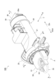
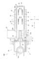
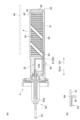
図2以降の必要な図を参照して、排水フィルタ100について詳細に説明する。図2及び図3は、それぞれ、排水フィルタ100の縦断面図及び斜視図である。排水フィルタ100は傾斜した状態(姿勢)で設置されているが、図2以降の各図では、この傾斜を考慮せずに、排水フィルタ100が単品として示されている。したがって、図2以降では、図1に示したX方向線(前後方向線)及びZ方向線(上下方向線)は省略されている。図4及び図5は、それぞれ、図3のIV-IV線に沿った断面図及びV-V線に沿った断面図である。
The
排水フィルタ100は、外槽6に接続された第1排水管16aから洗濯水を導入し通水することで洗濯水に含まれる異物を捕獲する。図2及び図3に示されるように、ケース20は、略円筒状のケース本体21と、例えばケース本体21の側面に接続された導入管25と、ケース本体21の後端に形成された円形の排出口26aとを備える。ケース本体21に対する導入管25の接続部には導入口25a(図5参照)が形成されている。ケース20の材料は特に限定されないが、ケース20は例えば樹脂製である。導入管25に第1排水管16aが接続され、排出口26aには排水ホースHが取り付けられ、またフィルタ組立体Aがケース本体21内に挿入されてケース本体21の挿入口27を閉塞することにより、ケース20は密閉性を有している。導入口25aは第1排水管16aを通じて洗濯水を導入し、排出口26aはフィルタ本体30を通過したろ過後の洗濯水を排出する。
The
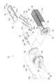
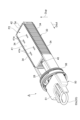
本実施形態に係る排水フィルタ100は、フィルタのメンテナンス性を考慮した構造及び機能を備えている。排水フィルタ100は、メンテナンス時に、フィルタ本体30に捕獲された異物を容易に脱水可能とし、使用者は異物にできるだけ触れずに異物を廃棄可能である。以下、各図を参照しながら排水フィルタ100における脱水機能等について説明する。図6は、フィルタ組立体Aの斜視図である。図6に示されるように、フィルタ組立体Aは、フィルタ本体30と、フィルタ本体30内に嵌め込まれた圧縮板40と、フィルタ本体30の手前側に取り付けられた操作部50とを備える。「手前」との用語は、洗濯機1の前(ドア3及びカバーBの前)にいる使用者を基準として用いられ、洗濯機1の前側と同意である。フィルタ組立体Aでは、これらが一体化されている。使用者は操作部50の着脱レバー51をつまんで回転させることにより、フィルタ組立体Aをケース20から容易に取り外し、また装着することができる。着脱レバー51はつまみとも呼ばれ、フィルタ組立体Aを一体的に取り外すための回転式のレバーである。
The
フィルタ組立体Aを構成する各部についても、例えば樹脂成形品が用いられる。部分的に金属が用いられてもよい。 The components of the filter assembly A may be made of resin molded parts, for example. Metal may also be used in some areas.
フィルタ本体30は、上方に開放された直方体形状を有する。フィルタ本体30は、長方形板状の底壁部31(図5参照)と、底壁部31の手前側に形成された断面U字状の基端壁部32と、基端壁部32の更に手前側に形成されたフランジ部33とを有する。フィルタ本体30は、ケース20の挿入口27を介してケース20内に挿入及び装着される(図2及び図4参照)。フィルタ本体30が装着された状態で、その後端部38はケース20の排出口26aから露出している。ケース20に対するフィルタ本体30の装着構造は特に限定されないが、後端部38が排出口26aよりも後方に突出してもよい。
The
図6に示されるように、フィルタ本体30は、底壁部31から立ち上がる複数の櫛歯34を有する。複数の櫛歯34は、底壁部31の一対の側辺部と、後端部38に近い短辺部に沿ってフィルタ本体30の一対の側壁及び後壁を形成するように配列されている。すべての櫛歯34は、平行であり、第1方向D1に延びている。一定の間隔をあけて立設された櫛歯34は、フィルタ本体30のろ過面を構成する。フィルタ本体30の基端壁部32には、導入口25aに対面する位置に開口36が形成されており、排水フィルタ100内に導入された洗濯水はフィルタ本体30の内部へと流入する。洗濯水は多数の櫛歯34からなるろ過面を通過する。これにより、糸屑等の異物が櫛歯34に引っ掛かり、捕獲される。ろ過後の洗濯水は、櫛歯34間の間隔(間隙)を通り抜けて排出口26aから排出される。
As shown in FIG. 6, the
第1方向D1は、底壁部31に垂直であるが、上述の通りケース20が傾斜しているため、フィルタ組立体Aも傾斜している。よって、第1方向D1は、XZ平面に平行に延びると共に、YZ平面に対しては所定角度をなす。フィルタ本体30のフランジ部33以外の部分(ろ過に関わる部分)は、ケース本体21内に嵌め込まれている。例えば、底壁部31、基端壁部32及び櫛歯34は、挿入口27において着脱レバー51が固定され、櫛歯34と天面21aの一部が当接することによってケース本体21内で一定の姿勢を保持している。底壁部31及び基端壁部32は、ケース本体21の内面のどこにも接触支持されず、下端部21bを含むケース本体21の周壁面から離間している。櫛歯34の上端は、ケース本体21の上部内面に形成された平坦な天面(受け面)21aに近接する。
The first direction D1 is perpendicular to the
図7に示されるように、圧縮板40は、複数の櫛歯34に包囲されたろ過空間内に収まる長方形板状の平板部41と、複数の櫛歯34に凹凸嵌合する周縁部42とを有する。図4及び図5に示されるように、平板部41はフィルタ本体30内に配置されている。櫛歯34の間隙に相当する数の突起(この突起も歯形状である)が、平板部41の一対の側辺部と、後部の短辺部に沿って並んでいる。周縁部42の突起と櫛歯34との間には隙間が存在する。この構成により、圧縮板40はフィルタ本体30内に嵌合すると共に、その嵌合状態が維持されたまま、フィルタ本体30内において第1方向D1に移動可能である。圧縮板40は、その姿勢を保ったまま略平行に移動する。言い換えれば、圧縮板40は、櫛歯34によって可動方向を規制されており、第1方向D1にのみ移動可能である。圧縮板40は、櫛歯34と嵌合する限りにおいて、第1方向D1以外には移動できない。圧縮板40の可動範囲の第1方向D1における距離は、櫛歯34の長さにほぼ相当する。
As shown in FIG. 7, the
なお、個々の櫛歯34において、周縁部42との嵌合及び圧縮板40のスライドを滑らかにするテーパ部(面取り部)が設けられてもよい。周縁部42においても、櫛歯34との嵌合及び圧縮板40のスライドを滑らかにするテーパ部(面取り部)が設けられてもよい。
Each
図3及び図4に示されるように、操作部50は、洗濯機1の外側、言い換えれば挿入口27の外側から操作可能である。カバーB(図1参照)を開ければ、使用者は開口2fを介して片手又は両手でフィルタ組立体Aを持つことができる。操作部50は、回転式の着脱レバー51と、着脱レバー51と一体に回転する嵌合・着脱部56とを有する。例えば、扁平な形状の着脱レバー51が左右方向に向くとき、嵌合・着脱部56によってフィルタ組立体Aはケース20に装着及び固定される。使用者によって着脱レバー51が反時計回りに約90度回転させられると、嵌合・着脱部56における嵌合状態が解除され、フィルタ組立体Aをケース20から取り外すことができる。フィルタ組立体Aは、例えば第1方向D1に直交する第2方向D2に沿って取り外される。フィルタ組立体Aの装着時も、上記とは逆の手順で、フィルタ組立体Aはケース20に装着される。第2方向D2も、例えばXZ平面に平行に延びる。
3 and 4, the
嵌合・着脱部56とケース20の挿入口27との間にはフィルタ本体30のフランジ部33が配置される。フランジ部33と挿入口27との間には、円環状のパッキン28(図7参照)が設けられてもよい。上記の嵌合状態では、嵌合・着脱部56が、フランジ部33及びパッキン28を介して挿入口27を閉鎖する。嵌合・着脱部56、フランジ部33及びパッキン28により、ケース20の水封がなされる。
The
操作部50は、第2方向D2に押し引き可能な操作レバー53を有する。操作レバー53は、第2方向D2に延びると共に、着脱レバー51の回転中心線Lに沿って配置された軸部53aを含む。操作レバー53は、着脱レバー51内に形成されたガイド部54に沿って直線状に移動する。操作レバー53は、指掛け部53cとガイド部54との嵌合により、回転中心線L周りの回転方向においては着脱レバー51と一体に回転する。しかし操作レバー53の押し引き動作と着脱レバー51の回転動作とは、互いに独立している。操作レバー53の環状の指掛け部53cに人差し指等を入れて操作レバー53を引っ張ることで、操作レバー53は引出し方向Doutに移動する。また操作レバー53をフィルタ本体30内に向けて押し込むことで、操作レバー53は押込み方向Dinに移動する。引出し方向Dout及び押込み方向Dinは第2方向D2に平行であり、回転中心線Lにも平行である。なお、圧縮コイルバネ(バネ部材)65の弾性係数を適宜に調整することにより、使用者が意識せずとも操作レバー53を自然に戻すことができる。このようにすれば、操作レバー53の戻し忘れを防止できる。
The operating
フィルタ組立体Aでは、フィルタ本体30内において圧縮板40が昇降することによって異物の脱水が可能となっている。フィルタ組立体Aは、更に、操作レバー53に連結され、操作レバー53の押し引きに応じて第2方向D2に往復運動する往復部材61を備える。往復部材61は圧縮板40に係合している(又は連結されている)。言い換えれば、フィルタ組立体Aは、操作レバー53の押し引きに応じて圧縮板40を第1方向D1に移動させる昇降機構60を備える。本実施形態の排水フィルタ100では、昇降機構60は、カム式の連動機構となっている。
In the filter assembly A, the
図7に示されるにように、昇降機構60は、平板状の往復部材61と、往復部材61の手前側に形成されて上方に突出する連結壁部62と、往復部材61から斜め方向に延びる互いに平行な4つのカム部材63とを有する。往復部材61は、連結壁部62の嵌合凹部62aに操作レバー53の連結端53bが嵌合する(例えばH形の嵌合)ことにより操作レバー53に連結される(図5も参照)。着脱レバー51の回転に伴い操作レバー53が回転しても、連結端53bは嵌合凹部62a上で空転し、嵌合凹部62aに対する連結端53bの嵌合状態は不変である。すなわち、操作レバー53は、往復部材61(昇降機構60)に対して回転自在に係合する。4つのカム部材63は往復部材61に一体的に形成されており、往復部材61に垂直でかつ第2方向D2に平行な平面内(すなわち第1方向D1と第2方向D2を含む平面内)において、第1方向D1と第2方向D2の何れとも角度をなす第3方向に延びる。4つのカム部材63は、櫛歯34に包囲されたろ過空間内に存在する。各カム部材63は、上記平面に延びる板状をなしており、左右方向(図3に示すY方向)に薄い。図7に示されるように、平板部41には、これら4つのカム部材63に対応して、カム部材63が挿通される4つのカム挿通孔41eが形成されている。各カム挿通孔41eは、上記第3方向から見て長方形状である。
7, the
図5に示されるように、往復部材61は、フィルタ本体30の底壁部31と圧縮板40の平板部41との間に配置される。往復部材61は、例えば底壁部31上に形成されたガイド溝に案内されて、第2方向D2に移動可能である。カム部材63の上端は、櫛歯34の上端とほぼ等しい高さに位置しており、上記した天面21aに近接している。昇降機構60の全体は、カム挿通孔41eにカム部材63が挿通され、圧縮板40が可動方向を規制されていることにより、第2方向D2にのみ移動可能である(そのようにカム部材63の第3方向が設定されている)。昇降機構60は、操作レバー53の押し引きに応じて往復部材61が第2方向D2に往復運動することで、圧縮板40を第1方向D1に移動させる。
5, the reciprocating
図5及び図8に示されるように、往復部材61の下面には、昇降機構60の第2方向D2における可動範囲を規制するための機構が設けられている。往復部材61の下面には、左右方向の中央の位置に突起64が設けられている。また底壁部31には、左右方向の中央の位置において、往復部材61が乗る面(接触面)よりも窪むと共に第2方向D2に延びる溝部31gが形成されている。この溝部31gに圧縮コイルバネ65が嵌まり込んでいる。圧縮コイルバネ65は、フィルタ本体30の基端壁部32と昇降機構60の突起64との間に介在されており、往復部材61の移動に伴って伸縮する。
As shown in Figs. 5 and 8, the underside of the reciprocating
図5に示される状態で、圧縮板40は底壁部31上に接触しており、圧縮板40は初期位置P1に位置する。圧縮コイルバネ65は、突起64に押されて自然長よりも若干圧縮されている。操作レバー53が引出し方向Doutに移動したとき、往復部材61も引出し方向Doutに移動する。突起64が圧縮コイルバネ65のバネ力に抗して引出し方向Doutに移動する。この移動に伴って、図8に示されるように、圧縮板40は上向きDupに移動する(上昇する)。図8に示される状態で、往復部材61の引出し方向Doutへの移動は、底壁部31に設けられた突起等に往復部材61が当接することにより制止される。このとき、圧縮板40は櫛歯34の上端に相当する上限位置P2に位置する。
5, the
例えば、第2方向D2に対する第3方向の角度は45°である。この場合、引出し方向Doutにおける操作レバー53のストローク(引張りストローク)と、上向きDupの圧縮板40のストローク(上昇ストローク)は等しくなる。第3方向が45°であると、力の伝達効率がもっとも高くなる。第2方向D2に対する第3方向の角度(カム角度)を大きくすると、操作レバー53のストロークは小さくなるが、力の伝達効率は低下する。
For example, the angle of the third direction relative to the second direction D2 is 45°. In this case, the stroke (pulling stroke) of the operating
また操作レバー53が押込み方向Dinに戻されたとき、往復部材61も押込み方向Dinに移動する。この移動に伴って、圧縮板40は下向きDdownに移動する(下降する)。上向きDup及び下向きDdownは、第1方向D1に略平行な向きである。圧縮板40は、昇降板と呼ぶこともできる。
When the operating
このように、昇降機構60には、引出し方向Doutに移動させられた往復部材61を押込み方向Din(逆向き)に付勢する圧縮コイルバネ65が設けられている。昇降機構60による圧縮板40の移動範囲は、櫛歯34の全長(上記した櫛歯34の長さ)の範囲内に規制されている。図9は、図8の斜視図である。圧縮板40が上限位置P2に位置するとき、圧縮板40の周縁部42は櫛歯34の上端に係合している。しかし、圧縮板40はそれ以上は上向きDupに移動する(上昇する)ことができないので、フィルタ本体30から脱落することはない。
In this way, the
このとき、圧縮板40は、ケース本体21の天面21aに近接するか、又は当接する。圧縮板40の上昇に伴い、櫛歯34に引っ掛かった異物は周縁部42によって、カム部材63に引っ掛かった異物は平板部41によって掻き取られ、持ち上げられる。4つのカム部材63により駆動力が伝達されるため、圧縮板40はスムーズにかつ安定して上昇し、異物を掻き取る。異物は、圧縮板40と天面21aとの間に挟まれて脱水される。
At this time, the
なお、図5、図7及び図8に示されるように、基端壁部32には、操作レバー53の連結端53bと連結壁部62(嵌合凹部62a)の嵌合部位を覆うトンネル状のフィルタ内カバー70が設けられている。フィルタ内カバー70は、軸部53a、連結端53b、及び連結壁部62(嵌合凹部62a)を保護する。例えば、ヘアピン等の大きく硬い異物混入があった場合でも、そのような異物による動作不良が未然に防止されている。フィルタ内カバー70に、昇降機構60の移動範囲を規制する機能(制止構造等)を持たせてもよい。またフィルタ内カバー70は、軸部53a周りを封止するOリング53fの抜け防止の機能も有する。Oリング53fとフィルタ内カバー70の間にはOリング押さえ53gが設けられている。フィルタ内カバー70はOリング押さえ53gと当接しており、Oリング53fの抜けを防止している。
As shown in Figs. 5, 7 and 8, the
使用者は、排水フィルタ100をメンテナンスする際、洗濯機1の停止中にまずカバーBを開ける。開口2fを介して例えば片手を差し込み、操作レバー53を引く。このとき、着脱レバー51は閉位置にある。嵌合・着脱部56はケース20に嵌合され、挿入口27を閉鎖している。フィルタ本体30内では、圧縮板40の上昇により異物が脱水される。脱水された異物は圧縮板40に付着又は固着することが考えられる。使用者は、場合によっては、操作レバー53を押し込み(元に戻し)、圧縮板40を下降させる。このとき、カム部材63が糸屑等を押込み方向Dinに押すため、付着又は固着が解消される。脱水時に生じた水分がフィルタ本体30内に若干量だけ残存するが、糸屑等がその水分を吸い取る(水分が糸屑等に戻る)ため、フィルタ本体30に残存する水の量は減る。
When performing maintenance on the
使用者は、着脱レバー51を開位置まで回転させて、フィルタ組立体Aを引き出す(ケース20から取り外す)。このとき、フィルタ組立体Aは、ケース本体21によって案内されながら引出し方向Doutに引き出される。そして使用者がフィルタ組立体Aを逆さに持ち、その状態で操作レバー53を引っ張ると、糸屑等の異物が、4つのカム部材63によって押し出されると同時にその自重により発生する慣性力によって容易に脱落する。あるいは、フィルタ本体30を振って慣性力で糸屑等の異物を脱落させてもよい。なお、着脱レバー51の回転と操作レバー53の押し引きは互いに独立しているので、圧縮板40の位置によらず、フィルタ組立体Aを取り外すことができる。
The user rotates the attachment/
排水フィルタ100によれば、洗濯水がフィルタ本体30の複数の櫛歯34を通過する際に、異物が捕獲される。メンテナンス時に、使用者が、操作レバー53を操作して圧縮板40を移動させると、圧縮板40がケース内面の天面21aに近接又は当接し、異物が脱水される。このとき、櫛歯34に引っ掛かった異物は周縁部42によって、カム部材63に引っ掛かった異物は平板部41によって掻き取られる。フィルタ本体30をケース20から取り外してフィルタ本体30の天地を逆にした上で、操作レバー53を引張り操作するか又はフィルタ本体30を振ることで、使用者は、できるだけ異物に触れずに異物を廃棄することができる。フィルタ本体30を取り外す前に、操作レバー53を再度操作して圧縮板40を戻すことで、フィルタ本体30内に滞留していた若干量の水分が異物(糸屑等)に吸い込まれる。これにより、フィルタ組立体Aを取り外した後にフィルタ本体30から水が落下する(床などを汚す)不具合を防止することができる。本実施形態の排水フィルタ100によれば、異物の脱水が可能であり、できるだけ異物に触れずに異物を廃棄可能である。
According to the
また本実施形態の洗濯機1によれば、フィルタ本体30にヌメリ又は黒カビ等が発生していた場合でも、使用者は、異物に触れることなく異物を廃棄でき、メンテナンス作業が快適になる。糸屑を圧縮・脱水することにより、フィルタ本体30内における糸屑の容積を減らすことで、メンテナンスの頻度を低減することもできる。
In addition, with the washing machine 1 of this embodiment, even if slime or black mold has developed on the
昇降機構60によれば、往復部材61とカム部材63が一体で第2方向D2に往復運動することで、圧縮板40を確実かつ容易に移動させることができる。
According to the
往復部材61は第2方向D2に移動させられた後に使用者が操作レバーを離すと、操作レバー53及び往復部材61が圧縮コイルバネ65のはたらきによって元に戻る。これにより、操作レバー53の戻し忘れを防止できる。操作レバー53が戻ると同時に圧縮板40も元に戻る。これにより、上記したフィルタ本体30内の水分の吸い取り効果が自動的に得られる。
When the user releases the operating lever after the reciprocating
昇降機構60による圧縮板40の第1方向D1の移動範囲は、複数の櫛歯34の全長の範囲内に規制される。これにより、圧縮板40の周縁部42は常にフィルタ本体30の複数の櫛歯34に嵌合する。言い換えれば、圧縮板40は櫛歯34によって拘束される。よって、圧縮板40がフィルタ本体30から脱落してしまうことを防止できる。
The range of movement of the
操作レバー53は、第2方向D2に延びると共に着脱レバー51の回転中心線Lに沿って配置された軸部53aを含む。これにより、着脱レバー51の回転位置にかかわらず操作レバー53を操作できる。また操作レバー53の位置にかかわらず着脱レバー51を操作できる。
The operating
続いて、図10及び図11を参照して、第2実施形態に係る排水フィルタについて説明する。図10に示される排水フィルタ100Aが先の実施形態に係る排水フィルタ100と違う点は、昇降機構60が、圧縮コイルバネ65に代えてストッパ39を備えた点である。図10(a)及び図10(b)に示されるように、ストッパ39は、底壁部31の一部が切り欠かれることで形成されている。ストッパ39は、底壁部31の左右方向の中央の位置において、往復部材61が乗る面(接触面)と同じ位置か、又は多少下がった位置に設けられている。第2方向D2に延びるストッパ39は、弾性(又は可撓性)を有しており、図10(b)に示される規制位置Paから、図11(b)に示される退避位置Pbへと移動可能(退避可能)である。先端がL字状を呈することで、フィルタ組立体Aが取り出された状態で、使用者の指先がストッパ39に引っ掛かる。ストッパ39は、規制位置Paでは突起64に接触して往復部材61を規制(制止)する。往復部材61が規制される位置は、上記実施形態における圧縮板40の上限位置P2に対応する。ストッパ39は、退避位置Pbでは、突起64の更なる移動を許容する。
Next, the drain filter according to the second embodiment will be described with reference to Figs. 10 and 11. The
この昇降機構60を備えた排水フィルタ100Aによれば、使用者がストッパ39を退避位置Pbへと退避させることで、往復部材61の移動範囲の制限が解除される。これに伴い、圧縮板40のフィルタ本体30に対する嵌合(拘束)が解かれ、図11(a)に示されるように、圧縮板40はフィルタ本体30から離脱可能となる。
With the
以上、本発明の実施形態について説明したが、本発明は上記実施形態に限られない。 The above describes an embodiment of the present invention, but the present invention is not limited to the above embodiment.
昇降機構60は、カム式の機構に限られず、他の機構が採用されてもよい。例えば、図図12に示される変形例に係る排水フィルタ100Bのように、リンク式の機構が採用されてもよい。図12(a)に示されるように、排水フィルタ100Bの昇降機構60は、操作レバー53に連結された往復部材61と、往復部材61と圧縮板40とを連結し、往復部材61の往復運動を圧縮板40の第1方向D1の移動に変換するリンク機構66と、を有する。
The
圧縮板40が初期位置P1に位置するとき、リンク部材68は倒れた状態である。例えば、4つの平行なリンク部材68が、平板部41と往復部材61との間に設けられている。各リンク部材68の上連結軸69aは、平板部41の裏面側に設けられた軸受部において回転可能に連結されている。また各リンク部材68の下連結軸69bは、往復部材61の裏面側に設けられた(又は往復部材61の厚みの範囲内に形成された)軸受部において回転可能に連結されている。4つの上連結軸69a及び4つの下連結軸69bは、平板部41及び往復部材61の範囲内における適宜の長方形の頂点の位置に設けられる。なお、各連結軸は、軸受部の方に取り付けられてもよいし、リンク部材68、平板部41、及び往復部材61の何れとも独立し、連結部に組み込まれた軸部品であってもよい。また軸部材が省略され、円盤とそれを径方向外方から保持する嵌合構造であって、周方向に互いに摺動可能な連結構造が採用されてもよい。
When the
4つのリンク部材68の可動空間を確保するため、平板部41の下面(裏面)には、リンク部材68を受け入れる穴部等が設けられてもよい。往復部材61には、リンク部材68を受け入れる凹部又は孔部が設けられてもよい。また底壁部31に、リンク部材68を受け入れる凹部又は孔部が設けられてもよい。
To ensure a movable space for the four
リンク式の昇降機構60によっても、図12(b)に示されるように、圧縮板40の第1方向D1の移動範囲は、複数の櫛歯34の全長の範囲内に規制されている。圧縮板40が上限位置P2に位置するとき、リンク部材68は所定角度で立った状態である。この昇降機構60を備えた排水フィルタ100Bによれば、上記した各実施形態と同様の作用・効果が奏される。またリンク機構66により、圧縮板40を確実かつ容易に移動させることができる。さらにフィルタ本体30内にカム部材63が突出することがないので、フィルタ本体30内において糸屑等を溜める容積を大きく出来る。つまりフィルタ本体30内のろ過空間を異物の除去に最大限活用することができる。よって、フィルタ本体30のお手入れも容易となる。また操作レバー53のストロークを小さくすることも可能である。
As shown in FIG. 12(b), the link-
リンク式の昇降機構60が採用された排水フィルタ100Bにおいても、圧縮板40を取り外すことができる。圧縮板40をフィルタ本体30内に復帰させる際は、下がった(倒れた)位置にある4つのリンク部材68に対して圧縮板40を圧入できる。圧縮板40を取り外すことで、圧縮板40の下方に糸屑が入り込んで溜まった場合でも、当該糸屑を除去可能である。
The
上記した各実施形態及び変形例以外に、別の連動機構が採用されてもよい。 Aside from the above-described embodiments and modifications, other interlocking mechanisms may be used.
排水フィルタ100A又は排水フィルタ100Bの昇降機構60において、往復部材61を押込み方向Dinに付勢する付勢部材等が設けられてもよい。
The
ケース本体21に対してフィルタ組立体A(フィルタ本体30等)が装着される方向は、第1方向D1である場合に限られず、第1方向D1に交差する方向であってもよい。排水フィルタが傾斜しておらず、水平に設置されていてもよい。
The direction in which the filter assembly A (filter
圧縮コイルバネ65を省略し、代わりにカバーB(図1参照)の裏面に突起部を設け、カバーBを閉じたときに突起部が操作レバー53を押し戻す構造を採ってもよい。その場合でも、操作レバー53の戻し忘れを防止できる。また圧縮コイルバネ65が無いため、操作レバー53の引張り力が軽減される。引張り力としては、異物を脱水するための力のみが必要である。
The
着脱レバーは回転式ではなく、フック等が挿入口27に係合するロック機構を有するレバー、又は、単に挿入口27に嵌入させるタイプのレバーであってもよい。着脱レバーは、ケース20の挿入口27を閉鎖して水封できる構造であればよい。
The detachment lever may not be a rotating type, but may be a lever with a locking mechanism in which a hook or the like engages with the
第1方向D1と第2方向D2とが90度以外の角度をもって交差してもよい。櫛歯34が延びる方向、及び、圧縮板40が移動可能な方向が、往復部材61の移動方向である第2方向D2に対して90度以外の角度をなしてもよい。
The first direction D1 and the second direction D2 may intersect at an angle other than 90 degrees. The direction in which the
本発明がドラム洗濯機以外の洗濯機、例えば縦型洗濯機に適用されてもよい。 The present invention may be applied to washing machines other than drum washing machines, such as vertical washing machines.
1…洗濯機、2…筐体、6…外槽、6b…窪み部、7…ドラム(洗濯槽)、9…駆動モータ、16…排水管、17…排水バルブ、20…ケース、21…ケース本体、21a…天面(受け面)、25a…導入口、26a…排出口、27…挿入口、30…フィルタ本体、34…櫛歯、39…ストッパ、40…圧縮板、41…平板部、41e…カム挿通孔、42…周縁部、50…操作部、51…着脱レバー、53…操作レバー、53a…軸部、54…ガイド部、60…昇降機構、61…往復部材、63…カム部材、64…突起、65…圧縮コイルバネ(バネ部材)、66…リンク機構、68…リンク部材、70…フィルタ内カバー、A…フィルタ組立体、D1…第1方向、D2…第2方向、L…回転中心線、P1…初期位置、P2…上限位置、Pa…規制位置、Pb…退避位置。 1... washing machine, 2... housing, 6... outer tub, 6b... recessed portion, 7... drum (washing tub), 9... drive motor, 16... drain pipe, 17... drain valve, 20... case, 21... case body, 21a... top surface (receiving surface), 25a... inlet, 26a... outlet, 27... insertion port, 30... filter body, 34... comb teeth, 39... stopper, 40... compression plate, 41... flat plate portion, 41e... cam insertion hole, 42... peripheral portion, 50... operation portion, 51... Detachable lever, 53...operating lever, 53a...shaft portion, 54...guide portion, 60...lifting mechanism, 61...reciprocating member, 63...cam member, 64...projection, 65...compression coil spring (spring member), 66...link mechanism, 68...link member, 70...filter inner cover, A...filter assembly, D1...first direction, D2...second direction, L...rotation center line, P1...initial position, P2...upper limit position, Pa...restricted position, Pb...retracted position.
Claims (8)
前記洗濯水を導入する導入口と、ろ過後の前記洗濯水を排出する排出口と、前記フィルタ本体が挿入される挿入口と、を有するケースと、
前記挿入口を介して前記ケース内に装着され、第1方向に延びる複数の櫛歯を有する前記フィルタ本体と、
前記フィルタ本体内に配置された平板部と前記複数の櫛歯に嵌合する周縁部とを有し、前記フィルタ本体内に嵌め込まれると共に前記フィルタ本体内において前記第1方向に移動可能な圧縮板と、
前記フィルタ本体に取り付けられて前記挿入口の外側から操作可能な操作部であって、前記第1方向に交差する第2方向に押し引き可能な操作レバーを有する操作部と、
前記操作レバーに連結され、前記操作レバーの押し引きに応じて前記第2方向に往復部材が往復運動することで前記圧縮板を前記第1方向に移動させる昇降機構と、を備え、
前記ケースの内面には、前記第1方向に移動した前記圧縮板に近接又は当接する受け面が形成されている、排水フィルタ。 A drainage filter that captures foreign matter contained in washing water by introducing washing water into a filter body and passing the water through the filter body,
a case having an inlet for introducing the washing water, an outlet for discharging the filtered washing water, and an insertion port into which the filter body is inserted;
the filter body is attached to the case through the insertion opening and has a plurality of comb teeth extending in a first direction;
a compression plate having a flat plate portion disposed within the filter body and a peripheral portion that fits onto the plurality of comb teeth, the compression plate being fitted within the filter body and movable within the filter body in the first direction;
an operating unit that is attached to the filter body and can be operated from the outside of the insertion opening, the operating unit having an operating lever that can be pushed and pulled in a second direction intersecting the first direction;
a lifting mechanism connected to the operating lever, the lifting mechanism moving the compression plate in the first direction by a reciprocating member in the second direction in response to pushing and pulling the operating lever,
A drainage filter, wherein a receiving surface is formed on an inner surface of the case, the receiving surface being in close proximity to or in contact with the compression plate moved in the first direction.
前記操作レバーに連結された前記往復部材と、
前記往復部材に一体的に形成され、前記第1方向と前記第2方向を含む平面内において前記第1方向と前記第2方向の何れとも角度をなす第3方向に延びるカム部材と、有し、
前記圧縮板には、前記カム部材が挿通される貫通孔が形成されている、請求項1に記載の排水フィルタ。 The lifting mechanism includes:
The reciprocating member connected to the operating lever;
a cam member that is integrally formed with the reciprocating member and extends in a third direction that is angled with both the first direction and the second direction within a plane that includes the first direction and the second direction,
The drainage filter according to claim 1 , wherein the compression plate is formed with a through hole through which the cam member is inserted.
前記操作レバーに連結された前記往復部材と、
前記往復部材と前記圧縮板とを連結し、前記往復部材の往復運動を前記圧縮板の前記第1方向の移動に変換するリンク機構と、を有する、請求項1に記載の排水フィルタ。 The lifting mechanism includes:
The reciprocating member connected to the operating lever;
The drainage filter according to claim 1 , further comprising: a link mechanism that connects the reciprocating member and the compression plate and converts the reciprocating motion of the reciprocating member into movement of the compression plate in the first direction.
前記ストッパは、前記往復部材に接触する規制位置から、前記往復部材の更なる移動を許容する退避位置へと退避可能である、請求項1~3の何れか一項に記載の排水フィルタ。 The lifting mechanism is provided with a stopper that restricts the range of movement of the reciprocating member,
The drainage filter according to any one of claims 1 to 3, wherein the stopper is retractable from a restricting position in which the stopper contacts the reciprocating member to a retracted position in which the stopper allows further movement of the reciprocating member.
前記操作レバーは、前記第2方向に延びると共に前記着脱レバーの回転中心線に沿って配置された軸部を含む、請求項1~3の何れか一項に記載の排水フィルタ。 the operation unit has a rotary attachment/detachment lever for integrally removing the filter body, the compression plate, and the lifting mechanism from the case,
The drain filter according to claim 1 , wherein the operating lever includes a shaft portion extending in the second direction and disposed along a rotation center line of the attachment/detachment lever.
前記外槽内に配置され、洗濯物が収容される洗濯槽と、
前記外槽に接続され、前記外槽内の洗濯水を排出する排水管と、
前記排水管に接続された請求項1~3の何れか一項に記載の前記排水フィルタと、を備える洗濯機。 An outer tank disposed within the housing;
A washing tub disposed in the outer tub and accommodating laundry;
A drain pipe connected to the outer tub for discharging washing water from the outer tub;
A washing machine comprising: the drain filter according to any one of claims 1 to 3, connected to the drain pipe.
Priority Applications (2)
| Application Number | Priority Date | Filing Date | Title |
|---|---|---|---|
| JP2023062373A JP7621621B2 (en) | 2023-04-06 | 2023-04-06 | Drainage filters and washing machines |
| PCT/CN2024/083465 WO2024207999A1 (en) | 2023-04-06 | 2024-03-25 | Drain filter and washing machine |
Applications Claiming Priority (1)
| Application Number | Priority Date | Filing Date | Title |
|---|---|---|---|
| JP2023062373A JP7621621B2 (en) | 2023-04-06 | 2023-04-06 | Drainage filters and washing machines |
Publications (2)
| Publication Number | Publication Date |
|---|---|
| JP2024148865A JP2024148865A (en) | 2024-10-18 |
| JP7621621B2 true JP7621621B2 (en) | 2025-01-27 |
Family
ID=92971059
Family Applications (1)
| Application Number | Title | Priority Date | Filing Date |
|---|---|---|---|
| JP2023062373A Active JP7621621B2 (en) | 2023-04-06 | 2023-04-06 | Drainage filters and washing machines |
Country Status (2)
| Country | Link |
|---|---|
| JP (1) | JP7621621B2 (en) |
| WO (1) | WO2024207999A1 (en) |
Citations (5)
| Publication number | Priority date | Publication date | Assignee | Title |
|---|---|---|---|---|
| JP2018153374A (en) | 2017-03-17 | 2018-10-04 | 日立アプライアンス株式会社 | Washing machine |
| JP2019110985A (en) | 2017-12-21 | 2019-07-11 | 株式会社コーワ | Lint filter and washing machine |
| JP2020103718A (en) | 2018-12-28 | 2020-07-09 | 青島海爾洗衣机有限公司QingDao Haier Washing Machine Co.,Ltd. | Washing machine |
| CN112064300A (en) | 2019-06-10 | 2020-12-11 | 青岛海尔洗衣机有限公司 | Washing machine thread scraps filter and washing machine using same |
| JP2021058465A (en) | 2019-10-08 | 2021-04-15 | シャープ株式会社 | Filter and washing machine using the same |
Family Cites Families (4)
| Publication number | Priority date | Publication date | Assignee | Title |
|---|---|---|---|---|
| US6427633B1 (en) * | 2000-11-10 | 2002-08-06 | Patsy Ogden | Pet brush with hair removal feature |
| JP2020195502A (en) * | 2019-05-31 | 2020-12-10 | シャープ株式会社 | Filter and washing machine using it |
| JP7372133B2 (en) * | 2019-12-18 | 2023-10-31 | 東芝ライフスタイル株式会社 | Clothes processing equipment, filter equipment |
| JP2022153777A (en) * | 2021-03-30 | 2022-10-13 | 日立グローバルライフソリューションズ株式会社 | Foreign material catching device and washing machine |
-
2023
- 2023-04-06 JP JP2023062373A patent/JP7621621B2/en active Active
-
2024
- 2024-03-25 WO PCT/CN2024/083465 patent/WO2024207999A1/en not_active Ceased
Patent Citations (5)
| Publication number | Priority date | Publication date | Assignee | Title |
|---|---|---|---|---|
| JP2018153374A (en) | 2017-03-17 | 2018-10-04 | 日立アプライアンス株式会社 | Washing machine |
| JP2019110985A (en) | 2017-12-21 | 2019-07-11 | 株式会社コーワ | Lint filter and washing machine |
| JP2020103718A (en) | 2018-12-28 | 2020-07-09 | 青島海爾洗衣机有限公司QingDao Haier Washing Machine Co.,Ltd. | Washing machine |
| CN112064300A (en) | 2019-06-10 | 2020-12-11 | 青岛海尔洗衣机有限公司 | Washing machine thread scraps filter and washing machine using same |
| JP2021058465A (en) | 2019-10-08 | 2021-04-15 | シャープ株式会社 | Filter and washing machine using the same |
Also Published As
| Publication number | Publication date |
|---|---|
| JP2024148865A (en) | 2024-10-18 |
| WO2024207999A1 (en) | 2024-10-10 |
Similar Documents
| Publication | Publication Date | Title |
|---|---|---|
| KR101348718B1 (en) | Apparatus for collecting foreign materials and washing machine having the same | |
| CN112011971B (en) | Filter and washing machine using the same | |
| EP1450661B1 (en) | Dispenser device particularly for dishwashing machines | |
| JP2024148865A (en) | Drainage filters and washing machines | |
| EP2876198B1 (en) | Washing machine with drawer assembly | |
| JP2024148867A (en) | Drainage filters and washing machines | |
| JP2014226176A (en) | Filtering device for washing machine and washing machine mounting the same | |
| JP7644443B2 (en) | Filter device and washing machine | |
| JP7561528B2 (en) | washing machine | |
| JP6691028B2 (en) | Washing machine | |
| JP2024148866A (en) | Drainage filters and washing machines | |
| JP2025146374A (en) | Drain filters and washing machines | |
| JP2025146375A (en) | Drain filters and washing machines | |
| JP7317781B2 (en) | DRY FILTER DEVICE AND WASHING MACHINE INCLUDING THE SAME | |
| JP2010136904A (en) | Dewatering-cum-washing machine | |
| CN111373089B (en) | Household appliance | |
| JP2024135315A (en) | Drainage filters and washing machines | |
| JP2025091269A (en) | washing machine | |
| JP7852855B2 (en) | Filter device and washing machine | |
| TWI677610B (en) | Washer dryer | |
| JP6800111B2 (en) | Washing and drying machine | |
| JP2019041820A (en) | Drum-type washing machine | |
| JP2025133555A (en) | washing machine | |
| TW201540893A (en) | Washing device | |
| CN119020979A (en) | Clothes dryer |
Legal Events
| Date | Code | Title | Description |
|---|---|---|---|
| A621 | Written request for application examination |
Free format text: JAPANESE INTERMEDIATE CODE: A621 Effective date: 20231016 |
|
| A131 | Notification of reasons for refusal |
Free format text: JAPANESE INTERMEDIATE CODE: A131 Effective date: 20240604 |
|
| A521 | Request for written amendment filed |
Free format text: JAPANESE INTERMEDIATE CODE: A523 Effective date: 20240903 |
|
| TRDD | Decision of grant or rejection written | ||
| A01 | Written decision to grant a patent or to grant a registration (utility model) |
Free format text: JAPANESE INTERMEDIATE CODE: A01 Effective date: 20241224 |
|
| A61 | First payment of annual fees (during grant procedure) |
Free format text: JAPANESE INTERMEDIATE CODE: A61 Effective date: 20250106 |
|
| R150 | Certificate of patent or registration of utility model |
Ref document number: 7621621 Country of ref document: JP Free format text: JAPANESE INTERMEDIATE CODE: R150 |