JP7561528B2 - washing machine - Google Patents

washing machine Download PDF

Info

Publication number
JP7561528B2
JP7561528B2 JP2020106081A JP2020106081A JP7561528B2 JP 7561528 B2 JP7561528 B2 JP 7561528B2 JP 2020106081 A JP2020106081 A JP 2020106081A JP 2020106081 A JP2020106081 A JP 2020106081A JP 7561528 B2 JP7561528 B2 JP 7561528B2
Authority
JP
Japan
Prior art keywords
tank
filter member
washing machine
treatment agent
laundry treatment
Prior art date
Legal status (The legal status is an assumption and is not a legal conclusion. Google has not performed a legal analysis and makes no representation as to the accuracy of the status listed.)
Active
Application number
JP2020106081A
Other languages
Japanese (ja)
Other versions
JP2022000122A (en
Inventor
裕士 遠藤
博司 西村
Current Assignee (The listed assignees may be inaccurate. Google has not performed a legal analysis and makes no representation or warranty as to the accuracy of the list.)
Toshiba Lifestyle Products and Services Corp
Original Assignee
Toshiba Lifestyle Products and Services Corp
Priority date (The priority date is an assumption and is not a legal conclusion. Google has not performed a legal analysis and makes no representation as to the accuracy of the date listed.)
Filing date
Publication date
Application filed by Toshiba Lifestyle Products and Services Corp filed Critical Toshiba Lifestyle Products and Services Corp
Priority to JP2020106081A priority Critical patent/JP7561528B2/en
Priority to CN202110399385.3A priority patent/CN113818217A/en
Publication of JP2022000122A publication Critical patent/JP2022000122A/en
Application granted granted Critical
Publication of JP7561528B2 publication Critical patent/JP7561528B2/en
Active legal-status Critical Current
Anticipated expiration legal-status Critical

Links

Images

Classifications

    • DTEXTILES; PAPER
    • D06TREATMENT OF TEXTILES OR THE LIKE; LAUNDERING; FLEXIBLE MATERIALS NOT OTHERWISE PROVIDED FOR
    • D06FLAUNDERING, DRYING, IRONING, PRESSING OR FOLDING TEXTILE ARTICLES
    • D06F39/00Details of washing machines not specific to a single type of machines covered by groups D06F9/00 - D06F27/00 
    • D06F39/02Devices for adding soap or other washing agents
    • D06F39/022Devices for adding soap or other washing agents in a liquid state

Landscapes

  • Engineering & Computer Science (AREA)
  • Textile Engineering (AREA)
  • Detail Structures Of Washing Machines And Dryers (AREA)

Description

本発明の実施形態は、洗濯機に関する。 An embodiment of the present invention relates to a washing machine.

近年、洗剤や柔軟剤などの衣類処理剤を自動投入用のタンク内に予め複数回分貯留しておき、運転中に必要量をタンクから自動的に水槽内へ投入する自動投入部を備えた洗濯機が開発されている。 In recent years, washing machines have been developed that are equipped with an automatic dispenser that stores multiple loads of laundry detergent, fabric softener, and other laundry treatment agents in a tank for automatic dispensing and automatically dispenses the required amount from the tank into the water tub during operation.

特開2017-74081号公報JP 2017-74081 A

自動投入用のタンクには、洗濯処理剤の原液が比較的長期間貯留されることとなる。そのため、洗濯処理剤が水分の蒸発により濃縮される等して、タンクの底部に固化してしまうことがある。固化した洗濯処理剤は、タンクを水で濯ぐだけでは簡単にとることができない。 The undiluted laundry treatment agent is stored in the automatic dispenser tank for a relatively long period of time. As a result, the laundry treatment agent can become concentrated due to evaporation of water, and can solidify at the bottom of the tank. Solidified laundry treatment agent cannot be easily removed by simply rinsing the tank with water.

そこで、ユーザが洗浄し易い自動投入用の処理剤タンクを備えた洗濯機を提供する。 Therefore, we provide a washing machine equipped with an automatic treatment agent tank that is easy for users to clean.

実施形態の洗濯機は、内部に衣類を収容する水槽と、前記水槽に所定量の洗濯処理剤を自動で投入する自動投入装置と、を備える。前記自動投入装置は、洗濯運転複数回分の量の洗濯処理剤を貯留可能でかつ外部に開放された開口部を有するタンクと、前記タンクに設けられて前記タンクの内部と外部とを連通し前記タンク内に貯留された前記洗濯処理剤を前記タンクの外部に吐出可能な吐出部と、前記タンク内に工具を用いることなく着脱可能に設けられて前記吐出部側の領域と前記開口部側の領域とを仕切り前記開口部から投入された前記洗濯処理剤が前記吐出部側へ流れる際に前記洗濯処理剤に含まれる異物を除去可能なフィルタ部材と、を有する。前記フィルタ部材は、前記洗濯処理剤を透過可能な複数の透過部と、前記開口部側の領域からユーザの指を掛けることが可能な取っ手部と、を有する。 The washing machine of the embodiment includes a water tub for storing clothes therein, and an automatic dispenser for automatically dispensing a predetermined amount of laundry treatment agent into the water tub. The automatic dispenser includes a tank capable of storing an amount of laundry treatment agent for multiple washing runs and having an opening open to the outside, a discharge part provided in the tank that communicates the inside and outside of the tank and can discharge the laundry treatment agent stored in the tank to the outside of the tank, and a filter member provided in the tank detachably without using tools, that separates an area on the discharge part side from an area on the opening part side, and that can remove foreign matter contained in the laundry treatment agent when the laundry treatment agent dispensed from the opening flows to the discharge part side. The filter member has a plurality of permeable parts that allow the laundry treatment agent to pass through, and a handle part on which a user's fingers can be hooked from the area on the opening part side.

一実施形態による洗濯機の一例の縦断側面図FIG. 1 is a longitudinal sectional side view of an example of a washing machine according to an embodiment; 一実施形態による洗濯機の一例について構成の一部の概要を示す図FIG. 1 is a diagram showing an outline of a part of a configuration of an example of a washing machine according to an embodiment; 一実施形態による洗濯機の一例についてトップカバーの一部を示す斜視図FIG. 1 is a perspective view showing a part of a top cover of an example of a washing machine according to an embodiment; 一実施形態による洗濯機の一例についてタンクの構成を示す分解斜視図FIG. 1 is an exploded perspective view showing a configuration of a tank in an example of a washing machine according to an embodiment; 一実施形態による洗濯機の一例のタンクの平面図FIG. 1 is a plan view of an example tank of a washing machine according to an embodiment; 一実施形態による洗濯機の一例について図5のA-Aに沿って示すタンクの断面図FIG. 6 is a cross-sectional view of a tank taken along line AA of FIG. 5 for an example of a washing machine according to an embodiment; 一実施形態による洗濯機の一例について図6のX7を拡大して示す図FIG. 7 is an enlarged view of X7 in FIG. 6 for an example of a washing machine according to an embodiment. 一実施形態による洗濯機の一例について図6のX8を拡大して示す図FIG. 7 is an enlarged view of X8 in FIG. 6 for an example of a washing machine according to an embodiment. その他の実施形態による洗濯機の一例について図5のA-Aに沿って示すタンクの断面図FIG. 6 is a cross-sectional view of a tank taken along line AA in FIG. 5 for an example of a washing machine according to another embodiment;

以下、一実施形態による洗濯機について、図面を参照して説明する。
図1を参照して、洗濯機1の概略構成について説明する。洗濯機1は、洗濯機本体10、水槽11、回転槽12、モータ13、排水弁14、注水装置30、及び自動投入装置40を備えている。なお、図1の左側を洗濯機1の前側とし、図1の右側を洗濯機1の後ろ側とする。この場合、通常ユーザは、洗濯機1の前側に位置するものとする。また、洗濯機1の設置面側つまり鉛直下側を、洗濯機1の下側とし、設置面と反対側つまり鉛直上側を、洗濯機1の上側とする。そして、洗濯機1の前後方向及び上下方向に対して直角な方向を、洗濯機1の幅方向すなわち左右方向とする。
Hereinafter, a washing machine according to an embodiment will be described with reference to the drawings.
The schematic configuration of the washing machine 1 will be described with reference to FIG. 1. The washing machine 1 includes a washing machine main body 10, a water tub 11, a rotating tub 12, a motor 13, a drain valve 14, a water injection device 30, and an automatic input device 40. The left side of FIG. 1 is the front side of the washing machine 1, and the right side of FIG. 1 is the rear side of the washing machine 1. In this case, it is assumed that a user is usually located at the front side of the washing machine 1. In addition, the side of the installation surface of the washing machine 1, i.e., the vertically lower side, is the lower side of the washing machine 1, and the opposite side of the installation surface, i.e., the vertically upper side, is the upper side of the washing machine 1. The direction perpendicular to the front-rear and up-down directions of the washing machine 1 is the width direction of the washing machine 1, i.e., the left-right direction.

本実施形態の洗濯機1は、回転槽12の回転軸が鉛直方向を向いたいわゆる縦軸型の洗濯機である。なお、洗濯機1は、いわゆる縦型の洗濯機に限られず、回転槽の回転軸が水平又は傾斜したいわゆるドラム式であっても良い。また、洗濯機1は、乾燥機能を備えていても良いし、備えていなくても良い。 The washing machine 1 of this embodiment is a so-called vertical axis type washing machine in which the rotation axis of the rotating tub 12 is oriented vertically. Note that the washing machine 1 is not limited to a so-called vertical type washing machine, and may be a so-called drum type washing machine in which the rotation axis of the rotating tub is horizontal or inclined. In addition, the washing machine 1 may or may not have a drying function.

洗濯機本体10は、図1に示すように、外箱21、トップカバー22、本体蓋23、及びバックカバー24を有する。外箱21は、洗濯機1の外殻を構成している。外箱21は、例えば鋼板等によって略矩形の箱状に形成されており、上側が開口している。水槽11は、洗濯機本体10の内部すなわち外箱21の内部に収容されている。回転槽12は、水槽11の内部に収容されている。水槽11は、上側が開口した有底円筒形状形成されている。 As shown in FIG. 1, the washing machine main body 10 has an outer box 21, a top cover 22, a main body lid 23, and a back cover 24. The outer box 21 forms the outer shell of the washing machine 1. The outer box 21 is formed into a substantially rectangular box shape, for example, from a steel plate, and is open at the top. The water tub 11 is housed inside the washing machine main body 10, i.e., inside the outer box 21. The spin tub 12 is housed inside the water tub 11. The water tub 11 is formed into a cylindrical shape with a bottom that is open at the top.

トップカバー22は、図1に示すようにトップカバー開口部221を有しており、矩形の環状に構成されている。トップカバー22は、外箱21の上部に設けられている。本体蓋23は、トップカバー22に設けられており、トップカバー開口部221を開閉する。バックカバー24は、洗濯機1の左右方向に長い矩形状に構成されている。バックカバー24は、トップカバー22上部の後端部に設けられている。 The top cover 22 has a top cover opening 221 as shown in FIG. 1 and is configured in a rectangular ring shape. The top cover 22 is provided on the upper part of the outer box 21. The main body lid 23 is provided on the top cover 22 and opens and closes the top cover opening 221. The back cover 24 is configured in a rectangular shape that is long in the left-right direction of the washing machine 1. The back cover 24 is provided at the rear end of the upper part of the top cover 22.

モータ13は、水槽11の底部の外側に設けられており、水槽11を貫いて回転槽12に接続されている。モータ13は、例えばアウターロータ型のDCブラシレスモータである。モータ13は、回転槽12を回転させる。 The motor 13 is provided on the outside of the bottom of the water tank 11 and is connected to the rotating tank 12 through the water tank 11. The motor 13 is, for example, an outer rotor type DC brushless motor. The motor 13 rotates the rotating tank 12.

排水弁14は、電磁駆動可能な液体用の開閉弁であり、図示しない制御装置によって駆動制御される。排水弁14の入力側は、水槽11内に接続されており、排水弁14の出力側は、洗濯機1の外部に接続されている。排水弁14は、水槽11内に貯留されている水を洗濯機1の外部に排水するための排水経路を開閉する。排水弁14が閉じると、水槽11内は水を貯留可能な状態となる。また、排水弁14が開くと、水槽11内に貯留された水が切外へ排水可能となる。 The drain valve 14 is an electromagnetically actuable opening and closing valve for liquid, and is controlled by a control device (not shown). The input side of the drain valve 14 is connected to the inside of the water tub 11, and the output side of the drain valve 14 is connected to the outside of the washing machine 1. The drain valve 14 opens and closes a drainage path for draining the water stored in the water tub 11 to the outside of the washing machine 1. When the drain valve 14 is closed, the water tub 11 is in a state in which water can be stored. Also, when the drain valve 14 is opened, the water stored in the water tub 11 can be drained to the outside.

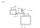
注水装置30は、洗濯機本体10内の上側後部であって、トップカバー22の内部に設けられている。注水装置30は、図2に示すように、給水弁31、注水ケース32、処理剤ケース33、及び注水ホース34を有している。注水装置30は、給水ホース100を介して、例えば図示しない水道の蛇口等外部の水源に接続される。 The water injection device 30 is provided at the upper rear of the washing machine main body 10, inside the top cover 22. As shown in FIG. 2, the water injection device 30 has a water supply valve 31, a water injection case 32, a treatment agent case 33, and a water injection hose 34. The water injection device 30 is connected to an external water source, such as a water faucet (not shown), via a water supply hose 100.

給水弁31は、電磁駆動可能な液体用の開閉弁であり、図示しない制御装置によって受動制御される。給水弁31の入力側は、水道等の外部の水源に接続されており、給水弁31の出力側は、注水ケース32に接続されている。給水弁31は、水道等の外部の水源から注水ケース32を介して水槽11内へ給水するための給水経路を開閉する。 The water supply valve 31 is an electromagnetically actuable opening and closing valve for liquid, and is passively controlled by a control device (not shown). The input side of the water supply valve 31 is connected to an external water source such as a water supply, and the output side of the water supply valve 31 is connected to a water supply case 32. The water supply valve 31 opens and closes a water supply path for supplying water from an external water source such as a water supply to the water tank 11 via the water supply case 32.

注水ケース32は、注水装置30の外殻を構成するものであり、例えば樹脂製であって箱状に形成されている。注水ケース32の上流側は給水弁31に接続されており、注水ケース32の下流側は注水ホース34を介して水槽11に接続されている。 The water injection case 32 constitutes the outer shell of the water injection device 30 and is made of, for example, resin and formed in a box shape. The upstream side of the water injection case 32 is connected to the water supply valve 31, and the downstream side of the water injection case 32 is connected to the water tank 11 via the water injection hose 34.

処理剤ケース33は、例えば樹脂製の容器であって、一回の洗濯運転で使用する量の洗剤及び柔軟剤等の洗濯処理剤を収容可能に構成されている。処理剤ケース33は、例えばトップカバー22の内部において前方へ引き出し可能に構成されている。処理剤ケース33は、注水ケース32内に収容された状態において、給水弁31を介して注水ケース32内に供給された水を受ける位置に設けられている。ユーザは、洗濯処理剤を手動で水槽11内に投入する場合に、処理剤ケース33を前方へ引き出した状態で、洗剤や柔軟剤を処理剤ケース33に投入する。処理剤ケース33内に貯留された洗濯処理剤は、注水装置30を介して水槽11に注水される水と共に水槽11内に流し落とされる。 The treatment agent case 33 is, for example, a resin container, and is configured to be able to store laundry treatment agents such as detergent and fabric softener in an amount to be used in one wash run. The treatment agent case 33 is configured, for example, to be able to be pulled out forward inside the top cover 22. When the treatment agent case 33 is housed in the water injection case 32, it is provided in a position to receive water supplied to the water injection case 32 via the water supply valve 31. When manually pouring laundry treatment agents into the water tub 11, the user pulls out the treatment agent case 33 forward and pours the detergent and fabric softener into the treatment agent case 33. The laundry treatment agents stored in the treatment agent case 33 are poured down into the water tub 11 together with the water poured into the water tub 11 via the water injection device 30.

自動投入装置40は、予め洗濯運転複数回分の洗濯処理剤を貯留しておき、複数回分の洗濯運転に亘って所定量の洗濯処理剤を自動で水槽11内に供給する機能を有している。本実施形態の場合、自動投入装置40は、図3に示すように、外箱21内で且つ水槽11の上方にあって、洗濯機1の左右方向の一方側寄り例えば左側寄りに設けられている。 The automatic dispenser 40 has the function of storing a quantity of laundry treatment agent for multiple wash runs in advance and automatically supplying a predetermined amount of laundry treatment agent to the water tub 11 over multiple wash runs. In the present embodiment, the automatic dispenser 40 is located inside the outer box 21 and above the water tub 11, as shown in FIG. 3, toward one side of the washing machine 1 in the left-right direction, for example toward the left side.

自動投入装置40は、図1~図3に示すように、供給ポンプ41、タンク収容部50、及びタンク60を有している。タンク収容部50は、洗濯機本体10に設けられており、タンク60を着脱可能に収容する。タンク60は、複数回分の洗濯処理剤を貯留可能に構成されており、ユーザの操作によってタンク収容部50に着脱される。 As shown in Figs. 1 to 3, the automatic dispenser 40 has a supply pump 41, a tank housing section 50, and a tank 60. The tank housing section 50 is provided in the washing machine main body 10 and houses the tank 60 in a detachable manner. The tank 60 is configured to be able to store multiple doses of laundry treatment agent, and is attached to and detached from the tank housing section 50 by the user's operation.

タンク収容部50は、図2に示すように、タンク収容部50の内部と外部とを連通する接続部51を有している。タンク60は、タンク60の内部と外部とを連通する吐出部611を有している。そして、タンク60がタンク収容部50の正しい位置に挿入されると、タンク60の挿入側の端部において吐出部611がタンク収容部50の接続部51に接続される。これにより、タンク60内に貯留されている洗濯処理剤が、吐出部611及び接続部51を通って、タンク60及びタンク収容部50の外部に流出可能になる。 As shown in FIG. 2, the tank storage section 50 has a connection section 51 that connects the inside and outside of the tank storage section 50. The tank 60 has a discharge section 611 that connects the inside and outside of the tank 60. When the tank 60 is inserted in the correct position in the tank storage section 50, the discharge section 611 is connected to the connection section 51 of the tank storage section 50 at the end of the tank 60 on the insertion side. This allows the laundry treatment agent stored in the tank 60 to flow out of the tank 60 and the tank storage section 50 through the discharge section 611 and the connection section 51.

供給ポンプ41は、例えばピストン式のポンプであり、タンク収容部50の外部に設けられて接続部51に接続されている。供給ポンプ41は、タンク60がタンク収容部50に収容されて吐出部611が接続部51に接続された状態で、タンク60から所定量の洗濯処理剤を吸出し、その吸い出した洗濯処理剤を上述した給水経路に投入する。洗濯機1は、例えば洗濯運転の洗い工程やすすぎ工程における注水中に供給ポンプ41を動作させることで、洗濯運転に必要な洗濯処理剤を、給水経路を流れる水に乗せて水槽11に投入することができる。なお、供給ポンプ41は、タンク60に設けても良いし、タンク収容部50の内部に設けても良い。 The supply pump 41 is, for example, a piston-type pump, and is provided outside the tank storage section 50 and connected to the connection section 51. When the tank 60 is stored in the tank storage section 50 and the discharge section 611 is connected to the connection section 51, the supply pump 41 draws out a predetermined amount of laundry treatment agent from the tank 60 and feeds the drawn out laundry treatment agent into the above-mentioned water supply path. The washing machine 1 can feed the laundry treatment agent required for the washing operation into the water tub 11 on the water flowing through the water supply path by operating the supply pump 41 during water injection in the washing step or rinsing step of the washing operation, for example. The supply pump 41 may be provided in the tank 60 or inside the tank storage section 50.

次にタンク収容部50及びタンク60の詳細について説明する。なお、以下の説明において、タンク収容部50及びタンク60の前後、上下、及び左右若しくは幅方向とは、ユーザが洗濯機1を使用する際に通常ユーザが立つと想定される位置を基準にしたものである。つまり、タンク収容部50及びタンク60の前後、上下、及び左右若しくは幅方向とは、洗濯機1の前後、上下、及び左右若しくは幅方向と必ずしも一致している必要はないが、本実施形態では説明の便宜上、洗濯機1の各方向の定義と一致させている。 Next, the tank storage section 50 and the tank 60 will be described in detail. In the following description, the front-rear, up-down, left-right, or width directions of the tank storage section 50 and the tank 60 are based on the position where a user is expected to normally stand when using the washing machine 1. In other words, the front-rear, up-down, left-right, or width directions of the tank storage section 50 and the tank 60 do not necessarily have to match the front-rear, up-down, left-right, or width directions of the washing machine 1, but in this embodiment, for convenience of description, they are defined to match the definitions of each direction of the washing machine 1.

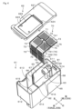
図3に示すように、タンク収容部50は、収容部本体52と、スライドケース53とを有する。収容部本体52は、タンク収容部50の外殻を構成する。収容部本体52は、略矩形の箱状に形成され、一方の面この場合前方が開口している。詳細は図示しないが、接続部51は、収容部本体52の開口とは反対側つまり後部に設けられている。 As shown in FIG. 3, the tank storage unit 50 has a storage unit main body 52 and a slide case 53. The storage unit main body 52 constitutes the outer shell of the tank storage unit 50. The storage unit main body 52 is formed in a roughly rectangular box shape, with one side, in this case the front, being open. Although not shown in detail, the connection part 51 is provided on the side opposite the opening of the storage unit main body 52, i.e., at the rear.

スライドケース53は、上部が開口した略矩形の箱状に形成され、収容部本体52の内部に引き出し可能に収容されている。スライドケース53が収容部本体52に出し入れされる際の、スライドケース53の移動方向を、スライドケース53又はタンク60の挿抜方向と称する。本実施形態の場合、スライドケース53又はタンク60の挿抜方向は前後方向である。そして、スライドケース53が収容部本体52から引き出される際の、スライドケース53の移動方向をスライドケース53又はタンク60の引き出し方向と称する。また、スライドケース53が収容部本体52に押し戻される際の、スライドケース53の移動方向をスライドケース53又はタンク60の挿入方向と称する。 The slide case 53 is formed in a generally rectangular box shape with an open top, and is housed inside the storage unit main body 52 so that it can be pulled out. The direction of movement of the slide case 53 when it is inserted into or removed from the storage unit main body 52 is referred to as the insertion/removal direction of the slide case 53 or the tank 60. In this embodiment, the insertion/removal direction of the slide case 53 or the tank 60 is the front-to-rear direction. The direction of movement of the slide case 53 when it is pulled out of the storage unit main body 52 is referred to as the pull-out direction of the slide case 53 or the tank 60. The direction of movement of the slide case 53 when it is pushed back into the storage unit main body 52 is referred to as the insertion direction of the slide case 53 or the tank 60.

収容部本体52は、受け部54を有する。受け部54は、収容部本体52の左右の内壁を収容部本体52の外部に向かって窪ませた溝形状に形成され、スライドケース53の挿抜方向に直線状に延びている。スライドケース53は、レール55を有する。レール55は、スライドケース53の左右の側面にそれぞれ設けられ、スライドケース53の挿抜方向つまりこの場合前後方向に直線状に延びる。レール55は、収容部本体52の受け部54に受け入れられ、スライドケース53の挿抜方向つまりこの場合前後方向への摺動を可能にする。収容部本体52、スライドケース53、レール55は、例えばいずれも樹脂製である。 The storage unit main body 52 has a receiving portion 54. The receiving portion 54 is formed in a groove shape by recessing the left and right inner walls of the storage unit main body 52 toward the outside of the storage unit main body 52, and extends linearly in the insertion and removal direction of the slide case 53. The slide case 53 has a rail 55. The rail 55 is provided on the left and right side surfaces of the slide case 53, respectively, and extends linearly in the insertion and removal direction of the slide case 53, that is, the front-to-rear direction in this case. The rail 55 is received by the receiving portion 54 of the storage unit main body 52, and enables the slide case 53 to slide in the insertion and removal direction, that is, the front-to-rear direction in this case. The storage unit main body 52, the slide case 53, and the rail 55 are all made of, for example, resin.

スライドケース53は、内部に複数この場合2個のタンク60を収容可能である。本実施形態の場合、2個のタンク60は、左右方向に並べてスライドケース53の内部に収容される。 The slide case 53 can accommodate multiple tanks 60 inside, in this case two tanks 60. In this embodiment, the two tanks 60 are accommodated inside the slide case 53, lined up in the left-right direction.

タンク60は、例えば合成樹脂製であって、前後方向又は左右方向に長い矩形状で中空の容器で構成されており、液状の洗濯処理剤を貯留することができる。この場合、タンク60は、複数回の洗濯運転で使用する洗濯処理剤を貯留するために十分な容量を有している。この場合、タンク60の容量は特に限定されないが、ユーザの利便性を考慮すると、少なくとも数百mL~2L程度に設定することが好ましい。また、本実施形態の場合、自動投入装置40は、タンク60を2つ有している。この場合、2つのタンク60のうち一方は、洗濯処理剤として洗剤を貯留するためのものである。また、2つのタンク60のうち他方は、洗濯処理剤として柔軟剤を貯留するためのものである。なお、これら2つのタンク60の容量は同一であっても良いし異なっていても良い。 The tank 60 is, for example, made of synthetic resin, and is configured as a hollow rectangular container that is long in the front-rear or left-right direction, and can store liquid laundry treatment agent. In this case, the tank 60 has a sufficient capacity to store laundry treatment agent to be used in multiple washing operations. In this case, the capacity of the tank 60 is not particularly limited, but it is preferable to set it to at least several hundred mL to about 2 L in consideration of user convenience. In addition, in the case of this embodiment, the automatic dispenser 40 has two tanks 60. In this case, one of the two tanks 60 is for storing detergent as a laundry treatment agent. In addition, the other of the two tanks 60 is for storing fabric softener as a laundry treatment agent. The capacity of these two tanks 60 may be the same or different.

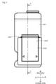
タンク60は、図4に示すように、タンク本体61、蓋部材62、吸込み管63、漏出防止弁64を有している。タンク本体61は、タンク60の外殻を構成している。 As shown in FIG. 4, the tank 60 has a tank body 61, a lid member 62, a suction pipe 63, and a leak prevention valve 64. The tank body 61 forms the outer shell of the tank 60.

本実施形態の場合、図3、図4、図6等に示すように、タンク本体61は、全体として直方体状に形成されており、前壁部612、側壁部613、背壁部614、及び底部615を有している。前壁部612は、タンク本体61の前面を構成する。側壁部613は、タンク本体61の側面を構成する。背壁部614は、タンク本体61の背面を構成する。底部615は、タンク本体61の底面を構成する。また、タンク本体61は開口部616を有している。開口部616は、タンク本体61の上部に設けられた開口、すなわち前壁部612、側壁部613、及び背壁部614に囲まれて形成された開口で、タンク本体61の内部をタンク本体61の外部に露出する。 In this embodiment, as shown in Figures 3, 4, 6, etc., the tank body 61 is formed in a rectangular parallelepiped shape as a whole, and has a front wall portion 612, a side wall portion 613, a rear wall portion 614, and a bottom portion 615. The front wall portion 612 constitutes the front surface of the tank body 61. The side wall portion 613 constitutes the side surface of the tank body 61. The rear wall portion 614 constitutes the rear surface of the tank body 61. The bottom portion 615 constitutes the bottom surface of the tank body 61. The tank body 61 also has an opening portion 616. The opening portion 616 is an opening provided in the upper portion of the tank body 61, that is, an opening surrounded by the front wall portion 612, the side wall portion 613, and the rear wall portion 614, and exposes the inside of the tank body 61 to the outside of the tank body 61.

図4、図5等に示すように、蓋部材62は、略矩形の板状に形成され、タンク本体61の上部に着脱可能に取り付けられて開口部616を閉塞する。蓋部材62は、蓋部材本体621と、投入口622と、開閉蓋623とを有する。蓋部材本体621は、蓋部材62の外殻を構成する。蓋部材本体621は、略矩形の板状に形成され、一部に投入口622を有する。投入口622は、ユーザが洗濯処理剤をタンク60に貯留する際に洗濯処理剤を投入する開口である。投入口622は、この場合、蓋部材本体621のうち、引き出し方向の端部つまり前端部よりの部分に設けられている。開閉蓋623は、蓋部材本体621にヒンジ部624を介して回動可能に設けられ、投入口622を開閉する。ヒンジ部624は、投入口622の挿入方向側に設けられている。 As shown in Figures 4 and 5, the cover member 62 is formed in a substantially rectangular plate shape and is detachably attached to the top of the tank body 61 to close the opening 616. The cover member 62 has a cover member main body 621, an input port 622, and an opening/closing cover 623. The cover member main body 621 constitutes the outer shell of the cover member 62. The cover member main body 621 is formed in a substantially rectangular plate shape and has an input port 622 in one part. The input port 622 is an opening through which the user inputs the laundry treatment agent when storing the laundry treatment agent in the tank 60. In this case, the input port 622 is provided at the end of the cover member main body 621 in the pull-out direction, i.e., the front end. The opening/closing cover 623 is rotatably provided on the cover member main body 621 via a hinge portion 624 to open and close the input port 622. The hinge portion 624 is provided on the insertion direction side of the input port 622.

ユーザは、タンク60に洗濯処理剤を注入する場合、まず、図3に示すようにタンク収容部50からスライドケース53ごとタンク60を引き出す。そして、開閉蓋623を開き、投入口622を通して洗濯処理剤をタンク60に投入する。ユーザは、所定の量まで洗濯処理剤を投入した後、開閉蓋623を閉じ、再びスライドケース53ごとタンク60をタンク収容部50に押し戻す。なお、ユーザは、蓋部材62をタンク本体61から取り外して、開口部616から洗濯処理剤を投入しても良い。 When injecting laundry treatment agent into the tank 60, the user first pulls out the tank 60 together with the slide case 53 from the tank housing section 50 as shown in FIG. 3. Then, the opening and closing lid 623 is opened and the laundry treatment agent is poured into the tank 60 through the inlet 622. After the user has poured in a predetermined amount of laundry treatment agent, the user closes the opening and closing lid 623 and pushes the tank 60 together with the slide case 53 back into the tank housing section 50. Alternatively, the user may remove the lid member 62 from the tank body 61 and pour the laundry treatment agent through the opening 616.

吐出部611は、図4に示すようにタンク本体61の後部、この場合背壁部614に設けられている。吸込み管63は、吐出部611に接続されており、タンク本体の底部615の近傍まで垂直下方に延びる。吸込み管63の下端部は、タンク本体61の底部615からわずかに空間を隔てて位置している。なお、底部615のタンク本体61の内側の面は、前後方向及び左右方向に関して傾斜している。すなわち、底部615は、後方に向けて下降するように僅かに傾斜している。また、吸込み管63の下端部に対面する位置に向けて下降するように左右方向に傾斜している。これにより、吸込み管63の下端部に対面する位置に洗濯処理剤が流れやすくなる。 The discharge portion 611 is provided at the rear of the tank body 61, in this case at the back wall portion 614, as shown in FIG. 4. The suction pipe 63 is connected to the discharge portion 611 and extends vertically downward to the vicinity of the bottom portion 615 of the tank body. The lower end of the suction pipe 63 is located slightly spaced from the bottom portion 615 of the tank body 61. The inner surface of the tank body 61 at the bottom portion 615 is inclined in the front-rear and left-right directions. That is, the bottom portion 615 is slightly inclined so as to descend toward the rear. It is also inclined in the left-right direction so as to descend toward the position facing the lower end portion of the suction pipe 63. This makes it easier for the laundry treatment agent to flow to the position facing the lower end portion of the suction pipe 63.

漏出防止弁64は、吐出部611と吸込み管63との間に設けられている。漏出防止弁64は、タンク60がタンク収容部50から取り外されて、吐出部611が接続部51に接続されていない場合に、タンク本体61内に貯留されている洗濯処理剤が吐出部611からタンク本体61外部へ漏れ出ることを防止する機能を有する。漏出防止弁64は、吐出部611に接続部51が接続されている場合には、吐出部611と吸込み管63との間の経路を開く。これにより、供給ポンプ41は、タンク本体61内に貯留されている洗濯処理剤を吸い出すことが可能になる。一方、漏出防止弁64は、吐出部611に接続部51が接続されていない場合には、吐出部611と吸込み管63との間の経路を閉じ、これによりタンク本体61内の洗濯処理剤が吐出部611から外部へ流出することを防ぐ。 The leak prevention valve 64 is provided between the discharge part 611 and the suction pipe 63. When the tank 60 is removed from the tank storage part 50 and the discharge part 611 is not connected to the connection part 51, the leak prevention valve 64 has a function of preventing the laundry treatment agent stored in the tank body 61 from leaking from the discharge part 611 to the outside of the tank body 61. When the connection part 51 is connected to the discharge part 611, the leak prevention valve 64 opens the path between the discharge part 611 and the suction pipe 63. This allows the supply pump 41 to suck out the laundry treatment agent stored in the tank body 61. On the other hand, when the connection part 51 is not connected to the discharge part 611, the leak prevention valve 64 closes the path between the discharge part 611 and the suction pipe 63, thereby preventing the laundry treatment agent in the tank body 61 from leaking out to the outside from the discharge part 611.

タンク60は、更に、図4に示すようにフィルタ部材70を有する。フィルタ部材70は、図6に示すように、タンク本体61内に設けられて、タンク本体61の内部空間において、開口部616側の領域A1と、吸込み管63が設けられた吐出部611側の領域A2と、を仕切っている。これにより、フィルタ部材70は、投入口622からタンク本体61内に投入された洗濯処理剤が吸込み管63から供給ポンプ41に吸い込まれる際に、その洗濯処理剤中に含まれている埃などの異物を捕集する機能を有する。 The tank 60 further includes a filter member 70 as shown in FIG. 4. As shown in FIG. 6, the filter member 70 is provided in the tank body 61, and divides the internal space of the tank body 61 into an area A1 on the opening 616 side and an area A2 on the discharge part 611 side where the suction pipe 63 is provided. As a result, the filter member 70 has the function of collecting foreign matter such as dust contained in the laundry treatment agent when the laundry treatment agent is introduced into the tank body 61 from the introduction port 622 and sucked into the supply pump 41 through the suction pipe 63.

フィルタ部材70は、板材をL字状に曲げた形状に形成されている。そのため、フィルタ部材70は、上面部71と、側面部72と、を有する。上面部71は、水平方向に延びる略矩形の板状に形成され、フィルタ部材70の上面を構成する。側面部72は、鉛直方向に延びる略矩形の板状に形成され、フィルタ部材70の側面この場合前面を構成する。上面部71の後端部つまり挿入方向側の端部は、図6及び図7にも示すように、タンク本体61の背壁部614内面にほぼ当接している。具体的には、上面部71の後端部は、タンク本体61の背壁部614の上下方向の中心部よりも上方であって、背壁部614の上端部よりも下方にほぼ当接している。側面部72の下端部は、図6及び図8にも示すように、タンク本体61の底部615の前後方向の中心部付近にほぼ当接している。具体的には、側面部72の下端部は、底部615の前後方向の中心部付近にほぼ当接している。なお、本明細書において、「ほぼ当接」とは、完全に当接している必要はなく、若干の隙間は許容されることを意味する。 The filter member 70 is formed in a shape obtained by bending a plate material into an L-shape. Therefore, the filter member 70 has an upper surface portion 71 and a side surface portion 72. The upper surface portion 71 is formed in a substantially rectangular plate shape extending in the horizontal direction, and constitutes the upper surface of the filter member 70. The side surface portion 72 is formed in a substantially rectangular plate shape extending in the vertical direction, and constitutes the side surface (in this case, the front surface) of the filter member 70. The rear end portion of the upper surface portion 71, that is, the end portion on the insertion direction side, is almost abutted against the inner surface of the rear wall portion 614 of the tank body 61, as shown in Figures 6 and 7. Specifically, the rear end portion of the upper surface portion 71 is above the center of the rear wall portion 614 of the tank body 61 in the vertical direction, and is almost abutted below the upper end portion of the rear wall portion 614. The lower end portion of the side surface portion 72 is almost abutted against the vicinity of the center of the bottom portion 615 of the tank body 61 in the front-rear direction, as shown in Figures 6 and 8. Specifically, the lower end of the side surface portion 72 is substantially in contact with the center of the bottom portion 615 in the front-to-rear direction. In this specification, "substantially in contact" does not necessarily mean that there is complete contact, but rather that a slight gap is permitted.

図4に示すように、フィルタ部材70は、枠部73と、複数この場合4個の透過部74と、を有する。枠部73は、上面部71と側面部72との全面に亘って、フィルタ部材70の外殻を構成する。また、枠部73は、フィルタ部材70の上面部71と側面部72との全面に亘って、矩形の環状を複数連ねた格子形状を形成している。この場合、枠部73は、上面部71に4つ、側面部72に4つ、併せて8つの格子を形成している。 As shown in FIG. 4, the filter member 70 has a frame portion 73 and a plurality of transmission portions 74 (four in this case). The frame portion 73 constitutes the outer shell of the filter member 70 over the entire surfaces of the top surface portion 71 and the side surface portion 72. The frame portion 73 also forms a lattice shape of multiple rectangular rings over the entire surfaces of the top surface portion 71 and the side surface portion 72 of the filter member 70. In this case, the frame portion 73 forms a total of eight lattices, four on the top surface portion 71 and four on the side surface portion 72.

複数の透過部74は、枠部73の複数の格子の内側をそれぞれ覆うように設けられている。各透過部74は、多数の小孔741を有し、洗濯処理剤の通過を許すが異物の透過を阻害する。これにより、複数の透過部74は、フィルタ部材70による異物の捕集を可能にする。 The multiple transmission sections 74 are provided so as to cover the insides of the multiple lattices of the frame section 73. Each transmission section 74 has many small holes 741 that allow the laundry treatment agent to pass through but prevent foreign matter from passing through. This allows the multiple transmission sections 74 to capture foreign matter by the filter member 70.

また、フィルタ部材70は、図4に示すように、一又は複数のリブ75を有する。リブ75は、上面部71又は側面部72から垂直方向に突出して設けられている。この場合、リブ75は、フィルタ部材70に対して、開口部616側の領域A1に向けて突出している。つまり、リブ75は、上面部71から上方に向かって、又は側面部72から前方すなわち引き出し方向に向かって突出している。また、リブ75は、枠部73に沿って設けられている。つまり、リブ75は、透過部74を避けた位置に設けられている。 As shown in FIG. 4, the filter member 70 has one or more ribs 75. The ribs 75 are provided so as to protrude vertically from the top surface portion 71 or the side surface portion 72. In this case, the ribs 75 protrude from the filter member 70 toward the area A1 on the opening 616 side. In other words, the ribs 75 protrude upward from the top surface portion 71 or forward from the side surface portion 72, i.e., in the pull-out direction. The ribs 75 are provided along the frame portion 73. In other words, the ribs 75 are provided at a position that avoids the transmission portion 74.

本実施形態では、リブ75は、フィルタ部材70の上面部71に4本、側面部72に4本設けられている。上面部71に設けられたリブ75のうち、3本は前後方向つまり挿抜方向に平行に延び、1本は左右方向に平行に延びる。上面部71に設けられた挿抜方向に平行に延びるリブ75は、上面部71の左右の両端部と、左右方向に関して中央部分とに位置する枠部73に沿って設けられている。上面部71に設けられた左右方向に平行に延びるリブ75は、上面部71の挿抜方向に関して中央部分に位置する枠部73に沿って設けられている。 In this embodiment, four ribs 75 are provided on the top surface portion 71 of the filter member 70, and four ribs 75 are provided on the side surface portion 72. Of the ribs 75 provided on the top surface portion 71, three extend parallel to the front-rear direction, i.e., the insertion/removal direction, and one extends parallel to the left-right direction. The ribs 75 provided on the top surface portion 71 that extend parallel to the insertion/removal direction are provided along the frame portion 73 located at both left and right ends of the top surface portion 71 and at the center portion in the left-right direction. The ribs 75 provided on the top surface portion 71 that extend parallel to the left-right direction are provided along the frame portion 73 located at the center portion in the insertion/removal direction of the top surface portion 71.

更に、側面部72に設けられたリブ75のうち、3本は上下方向に平行に延び、1本は左右方向に平行に延びる。側面部72に設けられた上下方向に平行に延びるリブ75は、側面部72の左右の両端部と、左右方向に関して中央部分とに位置する枠部73に沿って設けられている。側面部72に設けられた左右方向に平行に延びるリブ75は、側面部72の上下方向に関して中央部分に位置する枠部73に沿って設けられている。なお、本実施形態では、上面部71に設けられた挿抜方向に平行に延びる3本のリブ75と、側面部72に設けられた上下方向に平行に延びる3本のリブ75とは、上面部71と側面部72との設置部分で接続しているが、別の実施形態では、接続していなくても良い。 Furthermore, of the ribs 75 provided on the side portion 72, three extend parallel to the vertical direction, and one extends parallel to the horizontal direction. The ribs 75 provided on the side portion 72 extending parallel to the vertical direction are provided along the frame portion 73 located at both left and right ends of the side portion 72 and at the center portion in the horizontal direction. The ribs 75 provided on the side portion 72 extending parallel to the horizontal direction are provided along the frame portion 73 located at the center portion in the vertical direction of the side portion 72. In this embodiment, the three ribs 75 provided on the top portion 71 extending parallel to the insertion/removal direction and the three ribs 75 provided on the side portion 72 extending parallel to the vertical direction are connected at the installation portion between the top portion 71 and the side portion 72, but in another embodiment, they may not be connected.

リブ75は、フィルタ部材70を補強する機能を有する。すなわち、透過部74には多数の小孔741が設けられているため、小孔がない場合と比較してフィルタ部材70は荷重や曲げ応力に対して機械的強度や剛性が劣る。リブ75は、フィルタ部材70の機械的強度を増加させ、変形しづらくする。 The ribs 75 function to reinforce the filter member 70. That is, because the transmission portion 74 has many small holes 741, the filter member 70 has inferior mechanical strength and rigidity against load and bending stress compared to a case without small holes. The ribs 75 increase the mechanical strength of the filter member 70, making it less susceptible to deformation.

次に、フィルタ部材70のタンク本体61への組付け機構について説明する。タンク本体61は、窪み部65と、突条部66と、溝部67と、支持部材68と、を更に有する。窪み部65は、左右の側壁部613において後ろ側部分つまり挿入方向の端部側部分の一部をタンク本体61の中心側に向かって窪ませて形成されている。この場合、窪み部65は、底部615と接する位置から、左右の側壁部613上下方向の中心部よりも上方であって、左右の側壁部613の上端部よりも下方まで延びている。突条部66は、左右の側壁部613からタンク本体61の中心側に突出して上下方向に直線状に延びる突条を形成している。突条部66は、窪み部65の前端部つまり引き出し方向側の端部からやや空間を隔てて設けられている。 Next, the mechanism for assembling the filter member 70 to the tank body 61 will be described. The tank body 61 further has a recess 65, a protrusion 66, a groove 67, and a support member 68. The recess 65 is formed by recessing a part of the rear portion, i.e., the end portion in the insertion direction, of the left and right side wall portions 613 toward the center of the tank body 61. In this case, the recess 65 extends from the position where it contacts the bottom 615 to a position above the center of the left and right side wall portions 613 in the vertical direction and below the upper end of the left and right side wall portions 613. The protrusion 66 forms a protrusion that protrudes from the left and right side wall portions 613 toward the center of the tank body 61 and extends linearly in the vertical direction. The protrusion 66 is provided slightly spaced from the front end of the recess 65, i.e., the end on the pull-out direction side.

溝部67は、窪み部65の前端部が左右の側壁部613に形成する段差と突条部66との間において、タンク本体61の中心側に向かって開口した溝形状を形成する。つまり溝部67は、上下方向に延びる直線状に形成され、タンク本体61の上下方向に延びる面この場合左右の側壁部613に設けられている。この場合、溝部67は、側壁部613の前後方向つまり挿抜方向の中心部付近に設けられている。 The groove 67 forms a groove shape that opens toward the center of the tank body 61 between the step that the front end of the recess 65 forms in the left and right side wall portions 613 and the protrusion 66. In other words, the groove 67 is formed in a straight line extending in the vertical direction and is provided on the surfaces that extend in the vertical direction of the tank body 61, in this case the left and right side wall portions 613. In this case, the groove 67 is provided near the center of the side wall portions 613 in the front-to-rear direction, i.e., the insertion/removal direction.

溝部67は、内部にフィルタ部材70の側面部72の左右の両端部を摺動可能に受け入れる。つまり、フィルタ部材70がタンク本体61に装着される際、フィルタ部材70の側面部72の左右の両端部は、溝部67内部を下側に向かって摺動する。そして、フィルタ部材70がタンク本体61に装着された状態において、側面部72の左右の両端部は溝部67に受け入れられている。なお、この場合、上面部71は、窪み部65の上端部が左右の側壁部613に形成する段差に上方からほぼ当接している。 The groove 67 slidably receives both left and right ends of the side surface 72 of the filter member 70. That is, when the filter member 70 is attached to the tank body 61, both left and right ends of the side surface 72 of the filter member 70 slide downward inside the groove 67. Then, when the filter member 70 is attached to the tank body 61, both left and right ends of the side surface 72 are received in the groove 67. In this case, the upper surface 71 is almost in contact from above with the steps formed by the upper ends of the recesses 65 in the left and right side wall portions 613.

支持部材68は、水平方向に延びる短冊状に形成され、フィルタ部材70の下方において、背壁部614からタンク本体61の中心側に向かって突出する。支持部材68は、フィルタ部材70がタンク本体61に装着された状態において、フィルタ部材70の上面部71の下側に当接する。 The support member 68 is formed in a horizontally extending rectangular shape and protrudes from the rear wall portion 614 toward the center of the tank body 61 below the filter member 70. When the filter member 70 is attached to the tank body 61, the support member 68 abuts against the underside of the upper surface portion 71 of the filter member 70.

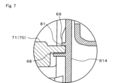
図6~図8に示すように、タンク本体61は、第1規制部81と、第2規制部82と、を更に有する。第1規制部81は、タンク本体61の上下方向に延びる面この場合背壁部614に設けられている。また、第1規制部81は、背壁部614の上下方向の中央部付近に設けられている。具体的には、第1規制部81は、背壁部614の上下方向の中心部よりも上方であって、背壁部614の上端部よりも下方に設けられている。また、第1規制部81は、背壁部614の左右方向の中央部に設けられている。第1規制部81は、フィルタ部材70の上面部71に係止して、フィルタ部材70の上方への移動を規制する機能を有する。具体的には、第1規制部81は、フィルタ部材70の上面部71の後端部つまり挿入方向側の端部に係止する。本実施形態の場合、第1規制部81は、フィルタ部材70の上面部71の後端部を、いわゆるスナップフィットにより係止する。 As shown in Figures 6 to 8, the tank body 61 further has a first restricting portion 81 and a second restricting portion 82. The first restricting portion 81 is provided on a surface extending in the vertical direction of the tank body 61, in this case the rear wall portion 614. The first restricting portion 81 is provided near the vertical center of the rear wall portion 614. Specifically, the first restricting portion 81 is provided above the vertical center of the rear wall portion 614 and below the upper end portion of the rear wall portion 614. The first restricting portion 81 is provided in the horizontal center of the rear wall portion 614. The first restricting portion 81 has a function of engaging with the upper surface portion 71 of the filter member 70 to restrict the upward movement of the filter member 70. Specifically, the first restricting portion 81 engages with the rear end portion of the upper surface portion 71 of the filter member 70, that is, the end portion on the insertion direction side. In this embodiment, the first restricting portion 81 engages the rear end of the upper surface portion 71 of the filter member 70 by a so-called snap fit.

この場合、第1規制部81は、左右方向に直線状に延び背壁部614からタンク本体61の中心側に向かって突出した突条を形成する。第1規制部81は、フィルタ部材70がタンク本体61に装着された状態において、フィルタ部材70の上面部71の上側に当接する。 In this case, the first restricting portion 81 forms a protrusion that extends linearly in the left-right direction and protrudes from the rear wall portion 614 toward the center of the tank body 61. When the filter member 70 is attached to the tank body 61, the first restricting portion 81 abuts against the upper side of the upper surface portion 71 of the filter member 70.

更に、タンク本体61は、1又は複数この場合3個のガイド部69を有する。ガイド部69は、上下方向に延びる短冊状に形成され、第1規制部81の上方において背壁部614から前方に突出して設けられている。ガイド部69は、図4及び図7に示すように、上部に傾斜が設けられている。つまり、ガイド部69は、前後方法つまり挿抜方向の長さ寸法である奥行きが、上部で小さく、下部で大きくなるように変化している。ガイド部69の下端部の奥行きは、第1規制部81の前後方法つまり挿抜方向の長さ寸法である奥行きと同一に設定されている。ガイド部69の上端部は、背壁部614と滑らかに接続し、ガイド部69の下端部は、第1規制部81の上面と滑らかに接続している。つまり、第1規制部81とガイド部69とは、一体に設けられている。 Furthermore, the tank body 61 has one or more (in this case, three) guide parts 69. The guide parts 69 are formed in strips extending in the vertical direction and are provided above the first restricting part 81, protruding forward from the back wall part 614. As shown in Figs. 4 and 7, the guide parts 69 are provided with an inclination at the upper part. That is, the guide parts 69 have a depth, which is the length dimension in the front-rear direction, i.e., the insertion/removal direction, which varies so that it is smaller at the upper part and larger at the lower part. The depth of the lower end part of the guide parts 69 is set to be the same as the depth, which is the length dimension in the front-rear direction, i.e., the insertion/removal direction, of the first restricting part 81. The upper end part of the guide parts 69 is smoothly connected to the back wall part 614, and the lower end part of the guide parts 69 is smoothly connected to the upper surface of the first restricting part 81. That is, the first restricting part 81 and the guide parts 69 are provided integrally.

ガイド部69は、フィルタ部材70をタンク本体61に設置する際にフィルタ部材70の後端部が第1規制部81を乗り越えやすくするためのガイドとして機能する。つまり、フィルタ部材70の上面部71の後端部がガイド部69の前方側の表面を上から下に向かって摺動することで、フィルタ部材70はガイド部69ひいては背壁部614を後方つまり挿入方向に向かって押すため、背壁部614が後方に向かって撓む。それにより、上面部71が第1規制部81を乗り越えることを容易にする。ガイド部69は背壁部614の左右方向に関する中央部に設けられていることで、フィルタ部材70を取り付ける際に背壁部614を撓みやすくしている。なお、第1規制部81、ガイド部69、突条部66、及び支持部材68は、いずれもタンク本体61と一体成形されている。 The guide portion 69 functions as a guide for making it easier for the rear end of the filter member 70 to overcome the first restricting portion 81 when the filter member 70 is installed in the tank body 61. In other words, when the rear end of the upper surface portion 71 of the filter member 70 slides from top to bottom on the front surface of the guide portion 69, the filter member 70 pushes the guide portion 69 and therefore the rear wall portion 614 backward, i.e., in the insertion direction, so that the rear wall portion 614 bends backward. This makes it easier for the upper surface portion 71 to overcome the first restricting portion 81. The guide portion 69 is provided in the center of the rear wall portion 614 in the left-right direction, making it easier for the rear wall portion 614 to bend when the filter member 70 is attached. The first restricting portion 81, the guide portion 69, the protrusion portion 66, and the support member 68 are all integrally molded with the tank body 61.

第2規制部82は、タンク本体61の底部615に設けられている。第2規制部82は、フィルタ部材70の側面部72に係止して、フィルタ部材70の底部615に沿った方向への移動を規制する。具体的には、第2規制部82は、フィルタ部材70の前後方向つまり挿抜方向への移動を規制する。第2規制部82は、フィルタ部材70の一方の端部この場合側面部72の下端部に係止する。この場合、第2規制部82は、底部615を下方に向かって窪ませ上方に向かって開口した左右方向に延びる直線状の溝形状を有する。そして、第2規制部82は、フィルタ部材70の側面部72の下端部を溝形状の内部に挟み込む。 The second restricting portion 82 is provided on the bottom 615 of the tank body 61. The second restricting portion 82 engages with the side portion 72 of the filter member 70 to restrict movement of the filter member 70 in a direction along the bottom 615. Specifically, the second restricting portion 82 restricts movement of the filter member 70 in the front-rear direction, i.e., the insertion/removal direction. The second restricting portion 82 engages with one end of the filter member 70, in this case the lower end of the side portion 72. In this case, the second restricting portion 82 has a linear groove shape that is recessed downward in the bottom 615 and opens upward and extends in the left-right direction. The second restricting portion 82 then sandwiches the lower end of the side portion 72 of the filter member 70 inside the groove shape.

フィルタ部材70は、更に取っ手部76を有する。取っ手部76は、枠部73に設けられ、枠部73から突出又は窪ませて形成されている。取っ手部76は、開口部616側の領域A1から、ユーザの指を掛けることが可能に構成されている。つまり、取っ手部76は、ユーザがフィルタ部材70をタンク本体61から取り外す際に、指を掛けて操作しやすくする機能を有する。 The filter member 70 further has a handle portion 76. The handle portion 76 is provided on the frame portion 73 and is formed by protruding or recessing from the frame portion 73. The handle portion 76 is configured so that a user can hook his/her finger from the area A1 on the opening 616 side. In other words, the handle portion 76 has the function of making it easier for the user to hook his/her finger and operate when removing the filter member 70 from the tank body 61.

本実施形態の場合、取っ手部76は、枠部73から開口部616側の領域A1に向かって突出して形成されている。この場合、取っ手部76は、上面部71又は側面部72から、上面部71又は側面部72に対して直角方向に突出させて形成されている。本実施形態では、取っ手部76は、上面部71から上方に向かって突出している。なお、別の実施形態では、取っ手部76は、例えば側面部72を前方つまり引き出し方向に向かって突出させて形成しても良い。 In this embodiment, the handle portion 76 is formed to protrude from the frame portion 73 toward the area A1 on the opening 616 side. In this case, the handle portion 76 is formed to protrude from the top surface portion 71 or the side surface portion 72 in a direction perpendicular to the top surface portion 71 or the side surface portion 72. In this embodiment, the handle portion 76 protrudes upward from the top surface portion 71. Note that in another embodiment, the handle portion 76 may be formed, for example, by protruding the side surface portion 72 forward, that is, in the pull-out direction.

この場合、取っ手部76は、上面部71のうち、4つの透過部74の中央に設けられている。具体的には、取っ手部76は、枠部73に設けられたリブ75と一体に設けられている。そして、取っ手部76は、背壁部614と平行に延びる板状に形成された第1部分761と、側壁部613と平行に延びる板状に形成された第2部分762とを有し、平面視でT字形を成している。これにより、第1部分761の後方側はフラットに形成されて指を掛けるエリアが確保されているため、ユーザは、例えば第1部分761に後方から指を掛けて操作しやすくなっている。この際、第1部分761に掛ける指は1本でもいいし、2本以上でもいい。また、この場合第2部分762は、第1部分761に掛かる荷重を支え、第1部分761の破損を防ぐ機能を有する。 In this case, the handle portion 76 is provided at the center of the four transparent portions 74 of the upper surface portion 71. Specifically, the handle portion 76 is provided integrally with the rib 75 provided on the frame portion 73. The handle portion 76 has a first portion 761 formed in a plate shape extending parallel to the back wall portion 614, and a second portion 762 formed in a plate shape extending parallel to the side wall portion 613, and forms a T-shape in a plan view. As a result, the rear side of the first portion 761 is formed flat to ensure an area for hanging fingers, making it easy for the user to operate the first portion 761 by hanging fingers from the rear, for example. At this time, the number of fingers hanging on the first portion 761 may be one or more. In addition, in this case, the second portion 762 has the function of supporting the load applied to the first portion 761 and preventing damage to the first portion 761.

なお、本実施形態では、第1部分761の後方に第2部分762を設けていないが、別の実施形態では、第1部分761の前方と後方とに第2部分762を設けて取っ手部76を平面視で十字形となるように形成しても良い。また、更に別の実施形態では、第1部分761の後方に第2部分762を設けて取っ手部76を平面視でT字形となるように形成しても良い。また、ユーザは、第2部分762を例えば2本又は3本の指で挟んで操作しても良い。 In this embodiment, the second portion 762 is not provided behind the first portion 761, but in another embodiment, the second portion 762 may be provided in front of and behind the first portion 761 to form the handle portion 76 in a cross shape in a plan view. In yet another embodiment , the second portion 762 may be provided behind the first portion 761 to form the handle portion 76 in an inverted T shape in a plan view. The user may also operate the second portion 762 by pinching it with, for example, two or three fingers.

ユーザがタンク60を洗浄する等のために、フィルタ部材70をタンク本体61から取り外す場合について説明する。まず、ユーザはタンク収容部50からタンク60を取り出す。そして、ユーザは蓋部材62をタンク本体61から取り外す。次に、ユーザは取っ手部76に指を掛けて、フィルタ部材70をタンク本体から取り外すことができる。 The following describes a case where a user removes the filter member 70 from the tank body 61 to clean the tank 60, etc. First, the user removes the tank 60 from the tank housing portion 50. Then, the user removes the lid member 62 from the tank body 61. Next, the user can place their fingers on the handle portion 76 to remove the filter member 70 from the tank body.

この際、まず、ユーザは、取っ手部76に指を掛ける。そして、ユーザは取っ手部76を手前に引っ張り、フィルタ部材70を弾性変形させて上面部71の後端部を第1規制部81の係止から解放させる。その際、ユーザは、例えば、第1部分761に後方から指を掛けることができる。またユーザは、第1部分761に掛けていない指を第1部分761の手前側に掛けて、いわばそれらの指で第1部分761を挟んで手前に引っ張っても良い。また、ユーザは、第1部分761に掛けていない指をフィルタ部材70の側面部72に掛けても良いし、どこにも掛けなくても良い。 At this time, the user first hooks his/her fingers on the handle portion 76. Then, the user pulls the handle portion 76 toward himself/herself, elastically deforming the filter member 70 and releasing the rear end portion of the upper surface portion 71 from the engagement of the first restricting portion 81. At this time, the user can, for example, hook his/her fingers on the first portion 761 from behind. The user can also hook the fingers that are not hooked on the first portion 761 on the front side of the first portion 761, so to speak, pinching the first portion 761 with those fingers and pulling it toward himself/herself. The user can also hook the fingers that are not hooked on the first portion 761 on the side portion 72 of the filter member 70, or not hook them anywhere.

その後、ユーザは、フィルタ部材70を上方に引っ張り、側面部72の下端部を第2規制部82の係止から解放させる。側面部72の左右の両端部は溝部67を摺動し、ユーザは、フィルタ部材70をタンク本体61から取り外すことができる。このようにして、ユーザは、工具を使うことなく、フィルタ部材70をタンク本体61から取り外すことができる。 Then, the user pulls the filter member 70 upward, releasing the lower end of the side portion 72 from the engagement of the second restricting portion 82. Both left and right ends of the side portion 72 slide in the groove portion 67, and the user can remove the filter member 70 from the tank body 61. In this way, the user can remove the filter member 70 from the tank body 61 without using tools.

そして、タンク本体61の内部を洗浄した後、上記と逆の手順により、フィルタ部材70をタンク本体61に取り付ける。この場合、まず、ユーザは、側面部72の左右の両端部を溝部67にはめ込み、溝部67内を下方に向かって摺動させる。ユーザは、側面部72の下端が第2規制部82に嵌まり込むまでフィルタ部材70を下方に向かって押し付ける。 After cleaning the inside of the tank body 61, the filter member 70 is attached to the tank body 61 by reversing the above procedure. In this case, the user first fits both left and right ends of the side portion 72 into the groove portion 67 and slides it downward inside the groove portion 67. The user presses the filter member 70 downward until the bottom end of the side portion 72 fits into the second restriction portion 82.

その後或いはそれと同時に、ユーザは、上面部71の後端部がガイド部69を通り過ぎて第1規制部81を乗り越えるまで上面部71を下方に押し込む。この際、ユーザは、取っ手部76に指を掛け、上面部71を前方つまり引き出し方向に向かって引っ張っても良いし、引っ張らなくても良い。上述のように、上面部71の後端部がガイド部69の傾斜の表面を摺動することで背壁部614が撓むので、上面部71の後端部は第1規制部81を乗り越えやすくなる。そして、上面部71の後端部が第1規制部81を乗り越えることで、上面部71の後端部は第1規制部81によって係止される。こうして、ユーザは、上面部71の後端部を第1規制部81によって係止し、側面部72の下端部を第2規制部82によって係止することで、フィルタ部材70をタンク本体61に固定することができる。 After that, or at the same time, the user pushes the upper surface portion 71 downward until the rear end of the upper surface portion 71 passes the guide portion 69 and overcomes the first restricting portion 81. At this time, the user may hook his/her finger on the handle portion 76 and pull the upper surface portion 71 forward, i.e., in the direction of pulling out the upper surface portion 71, or may not pull it. As described above, the rear end of the upper surface portion 71 slides on the inclined surface of the guide portion 69, causing the back wall portion 614 to bend, so that the rear end of the upper surface portion 71 becomes easier to overcome the first restricting portion 81. Then, as the rear end of the upper surface portion 71 overcomes the first restricting portion 81, the rear end of the upper surface portion 71 is locked by the first restricting portion 81. In this way, the user can fix the filter member 70 to the tank body 61 by locking the rear end of the upper surface portion 71 with the first restricting portion 81 and locking the lower end of the side portion 72 with the second restricting portion 82.

ここで、例えば自動投入装置40を長期間使用しないと、タンク本体61内に残存した洗濯処理剤が濃縮して底部615で固化することがある。更に、上述のように底部615は、吸込み管63周辺に洗濯処理剤を集めるため吸込み管63に向かって下降するように傾斜している。そのため、タンク本体61内の洗濯処理剤の残存量が少ないと、その洗濯処理剤は吸込み管63がある領域つまり吐出部611側の領域A2に溜まり易く、その結果、更に吸込み管63周辺で乾燥し固化しがちとなる。しかし、吐出部611側の領域A2は、通常フィルタ部材70によって開口部616側の領域A1と隔てられており、フィルタ部材70をタンク本体61から取り外さないと、固化した洗濯処理剤を洗浄することは困難である。 Here, for example, if the automatic dispenser 40 is not used for a long period of time, the laundry treatment agent remaining in the tank body 61 may become concentrated and solidify at the bottom 615. Furthermore, as described above, the bottom 615 is inclined downward toward the suction pipe 63 in order to collect the laundry treatment agent around the suction pipe 63. Therefore, if the amount of laundry treatment agent remaining in the tank body 61 is small, the laundry treatment agent tends to accumulate in the area where the suction pipe 63 is located, that is, in the area A2 on the discharge part 611 side, and as a result, it tends to dry out and solidify around the suction pipe 63. However, the area A2 on the discharge part 611 side is usually separated from the area A1 on the opening 616 side by the filter member 70, and it is difficult to wash the solidified laundry treatment agent unless the filter member 70 is removed from the tank body 61.

一方で、フィルタ部材70は洗濯運転時の振動等によって外れないように強固にタンク本体61に組み付けてあるため、ユーザがタンク本体の吐出部611側の領域A2を洗浄しようと思っても、特別な工具がないと取り外すことが容易ではない。 On the other hand, the filter member 70 is firmly attached to the tank body 61 so that it will not come off due to vibrations during the washing operation, etc., so even if a user wants to clean the area A2 on the discharge part 611 side of the tank body, it is not easy to remove it without special tools.

これに対し、以上説明した本実施形態の洗濯機1は、内部に衣類を収容する水槽11と、水槽11に所定量の洗濯処理剤を自動で投入する自動投入装置40と、を備える。自動投入装置40は、タンク60と、タンク60に設けられた吐出部611と、タンク60内に工具を用いることなく着脱可能に設けられたフィルタ部材70とを有する。タンク60は、洗濯運転複数回分の量の洗濯処理剤を貯留可能でかつ外部に開放された開口部616を有する。吐出部611は、タンク60の内部と外部とを連通し前記タンク内に貯留された前記洗濯処理剤を前記タンクの外部に吐出可能である。 In contrast, the washing machine 1 of the present embodiment described above includes a water tub 11 that holds clothes therein, and an automatic dispenser 40 that automatically dispenses a predetermined amount of laundry treatment agent into the water tub 11. The automatic dispenser 40 includes a tank 60, a discharge unit 611 provided in the tank 60, and a filter member 70 that is removably provided in the tank 60 without using tools. The tank 60 has an opening 616 that is capable of storing an amount of laundry treatment agent for multiple washing cycles and is open to the outside. The discharge unit 611 communicates between the inside and outside of the tank 60 and is capable of discharging the laundry treatment agent stored in the tank to the outside of the tank.

フィルタ部材70は、吐出部611側の領域A2と開口部616側の領域A1とを仕切り、開口部616から投入された洗濯処理剤が吐出部611側へ流れる際に洗濯処理剤に含まれる異物を除去可能である。フィルタ部材70は、洗濯処理剤を透過可能な複数の透過部74と、開口部616側の領域A1からユーザの指を掛けることが可能な取っ手部76と、を有する。 The filter member 70 separates the area A2 on the discharge portion 611 side from the area A1 on the opening 616 side, and can remove foreign matter contained in the laundry treatment agent when the laundry treatment agent poured in from the opening 616 flows toward the discharge portion 611 side. The filter member 70 has a plurality of transparent portions 74 that allow the laundry treatment agent to pass through, and a handle portion 76 on which the user can hang their fingers from the area A1 on the opening 616 side.

これによれば、フィルタ部材70は、取っ手部76に指を掛けることで、特別な工具がなくても簡単に取り外せるようになったので、タンク洗浄時のユーザの利便性が向上される。 As a result, the filter member 70 can be easily removed without special tools by hooking a finger on the handle portion 76, improving user convenience when cleaning the tank.

また、取っ手部76は、フィルタ部材70から開口部616側の領域A1に向かって突出している。これによれば、取っ手部76は、ユーザの位置する側に向かって突出しているため、ユーザが操作しやすくなり、更に容易にフィルタ部材70をタンク本体61から取り外すことができる。 The handle portion 76 also protrudes from the filter member 70 toward the area A1 on the opening 616 side. This makes it easier for the user to operate the handle portion 76, as it protrudes toward the side where the user is positioned, and allows the filter member 70 to be removed from the tank body 61 more easily.

更に、フィルタ部材70は、水平に延びる上面部71と、上下方向に延びる側面部72と、を有する。タンク60は、第1規制部81と、第2規制部82とを有する。第1は、タンク60の側面部72に設けられフィルタ部材70の上面部71に係止してフィルタ部材70の上方への移動を規制する。第2規制部82は、タンク60の底部615に設けられフィルタ部材70の側面部72に係止してフィルタ部材70の底部615に沿った方向への移動を規制する。取っ手部76は、上面部71又は側面部72の少なくともいずれか一方に設けられている。 Furthermore, the filter member 70 has a top surface portion 71 that extends horizontally and a side surface portion 72 that extends vertically. The tank 60 has a first restricting portion 81 and a second restricting portion 82. The first is provided on the side surface portion 72 of the tank 60 and engages with the top surface portion 71 of the filter member 70 to restrict the upward movement of the filter member 70. The second restricting portion 82 is provided on the bottom portion 615 of the tank 60 and engages with the side surface portion 72 of the filter member 70 to restrict the movement of the filter member 70 in a direction along the bottom portion 615. The handle portion 76 is provided on at least one of the top surface portion 71 or the side surface portion 72.

これによれば、取っ手部76は、ユーザから見て近い側つまりユーザからアプローチしやすい上面部71又は側面部72に設けられている。そのため、ユーザは取っ手部76に指を掛けやすくなり、一層ユーザの利便性が向上する。 According to this, the handle portion 76 is provided on the top surface portion 71 or the side surface portion 72, which is the side closest to the user, i.e., the side that is easiest for the user to approach. This makes it easier for the user to place their fingers on the handle portion 76, further improving user convenience.

更にまた、第1規制部81は、タンク60の上下方向に延びる面つまり背壁部614から突出して設けられて上面部71の端部を係止する機能を有している。これによれば、上面部71の後端部は第1規制部81により係止され、上方への移動が規制されている。これに対し、ユーザは、上面部71に設けられた取っ手部76を前方に引っ張って第1規制部81の規制を外した後、フィルタ部材70を上方に移動させることができる。このように、比較的簡単な構成でユーザのタンク60洗浄時の利便性を向上することができる。 Furthermore, the first restricting portion 81 protrudes from the surface that extends in the vertical direction of the tank 60, i.e., the back wall portion 614, and has the function of locking the end of the upper surface portion 71. As a result, the rear end of the upper surface portion 71 is locked by the first restricting portion 81, and its upward movement is restricted. In response, the user can pull the handle portion 76 provided on the upper surface portion 71 forward to release the restriction of the first restricting portion 81, and then move the filter member 70 upward. In this way, the convenience of the user when cleaning the tank 60 can be improved with a relatively simple configuration.

更にまた、第2規制部82は、タンク60の底部615を溝状に窪ませて形成されて側面部72の下端部を溝状の内側に挟み込んで側面部72の下端部を係止する機能を有している。これによれば、第2規制部82によってフィルタ部材70の前後方向つまり挿抜方向への移動が規制されるので、洗濯運転時に振動等があってもフィルタ部材は十分にタンク本体61に固定される。 Furthermore, the second restricting portion 82 is formed by recessing the bottom 615 of the tank 60 into a groove shape, and has the function of clamping the lower end of the side portion 72 inside the groove shape to lock the lower end of the side portion 72. As a result, the second restricting portion 82 restricts the movement of the filter member 70 in the front-to-rear direction, i.e., the insertion/removal direction, so that the filter member is sufficiently fixed to the tank body 61 even if there is vibration during the washing operation.

フィルタ部材70は、フィルタ部材70の他に、タンク60に取り付けるための構造を有しておらず、フィルタ部材70の端部が直接第1規制部81及び第2規制部82に係止される。これによれば、フィルタ部材70自体には爪部等が設けられていないため、フィルタ部材70は、タンクの第1規制部81及び第2規制部82の係止から解放されると、スムーズに外すことができる。また、フィルタ部材70形状をシンプルにできるため、フィルタ部材70の製造性ひいては、洗濯機1の製造性を向上することができる。 The filter member 70 does not have any structure for attaching it to the tank 60 other than the filter member 70, and the ends of the filter member 70 are directly engaged with the first restricting portion 81 and the second restricting portion 82. As a result, since the filter member 70 itself does not have any claws or the like, the filter member 70 can be smoothly removed when it is released from the engagement of the first restricting portion 81 and the second restricting portion 82 of the tank. In addition, since the shape of the filter member 70 can be simplified, the manufacturability of the filter member 70 and therefore the manufacturability of the washing machine 1 can be improved.

フィルタ部材は、透過部74を避けた位置に設けられてフィルタ部材70を補強する機能を有するリブ75を有する。取っ手部76は、リブ75と一体に設けられている。これによれば、補強用のリブ75と一体に取っ手部76を設けたため、リブ75による補強効果をより向上することができる。更に、取っ手部76は、透過部74を避けた位置に設けられているため、透過部74による洗濯処理剤のろ過機能を低下させることが抑制される。 The filter member has a rib 75 that is provided at a position that avoids the permeable portion 74 and has the function of reinforcing the filter member 70. The handle portion 76 is provided integrally with the rib 75. As a result, the handle portion 76 is provided integrally with the reinforcing rib 75, so the reinforcing effect of the rib 75 can be further improved. Furthermore, since the handle portion 76 is provided at a position that avoids the permeable portion 74, the filtering function of the permeable portion 74 for filtering laundry treatment agents is prevented from being reduced.

更に、別の実施形態では、フィルタ部材70は、図9に示すように、取っ手部76の代わりに、取っ手部77を有していても良い。取っ手部77は、上面部71又は側面部72を、吐出部611側の領域A2に向かって窪ませて形成しても良い。つまり、取っ手部77は、上面部71を下方に向かって窪ませて、又は側面部72を後方つまり挿入方向に向かって窪ませて形成しても良い。図9に示す実施形態の場合、取っ手部77は、上面部71に設けられ、上面部71を下方に向かって窪ませて形成されている。この場合も、ユーザは、取っ手部77に指を掛けて、フィルタ部材70を簡便にタンク本体61から取り外すことができるので、上記と同様の効果が奏される。 In another embodiment, the filter member 70 may have a handle portion 77 instead of the handle portion 76, as shown in FIG. 9. The handle portion 77 may be formed by recessing the upper surface portion 71 or the side surface portion 72 toward the area A2 on the discharge portion 611 side. In other words, the handle portion 77 may be formed by recessing the upper surface portion 71 downward, or recessing the side surface portion 72 toward the rear, i.e., the insertion direction. In the embodiment shown in FIG. 9, the handle portion 77 is provided on the upper surface portion 71, and is formed by recessing the upper surface portion 71 downward. In this case, the user can also easily remove the filter member 70 from the tank body 61 by hooking their fingers on the handle portion 77, so that the same effect as above is achieved.

なお、第1規制部81と第2規制部82とは、必ずしも両方が必要な訳ではなく、どちらか一方のみを設ける構成としても良い。その場合であっても、取っ手部76に指を引掛けることにより、ユーザは、フィルタ部材70をタンク本体61から簡便に取り外すことができる。 It should be noted that both the first restricting portion 81 and the second restricting portion 82 are not necessarily required, and a configuration in which only one of them is provided may be used. Even in this case, the user can easily remove the filter member 70 from the tank body 61 by hooking their finger on the handle portion 76.

また、上記の実施形態では、第1規制部81は、スナップフィットによってフィルタ部材70の移動を規制するが、移動の規制の方式はこれに限らない。例えば、第1規制部81は、フィルタ部材70の上面部71の端部に設けられた凸形状又は凹形状に対応して形成された凹形状又は凸形状であり、互いに嵌合してフィルタ部材70の上方への移動を規制しても良い。 In the above embodiment, the first restricting portion 81 restricts the movement of the filter member 70 by snap-fitting, but the method of restricting the movement is not limited to this. For example, the first restricting portion 81 may be a concave or convex shape formed corresponding to a convex or concave shape provided at the end of the upper surface portion 71 of the filter member 70, and may engage with each other to restrict the upward movement of the filter member 70.

更に、第1規制部81に替え、蓋部材62に下方に向かって突出する突形状を設け、当該突形状によって、フィルタ部材70の上面部71を下方に向かって押さえつけることで、フィルタ部材70の上下方向への移動を規制する方式であっても良い。 Furthermore, instead of the first restricting portion 81, a protrusion that protrudes downward may be provided on the cover member 62, and the protrusion may be used to press the upper surface portion 71 of the filter member 70 downward, thereby restricting the movement of the filter member 70 in the vertical direction.

なお、図面は上記の説明と併せて参照したときに分かりやすくなるように描いてあり、そのため必ずしも一定の縮尺や正確な角度によって表されたものではない。 Please note that the drawings are drawn to facilitate understanding when viewed in conjunction with the above description, and therefore are not necessarily drawn to scale or at precise angles.

以上、本発明の複数の実施形態を説明したが、これらの実施形態は、例として提示したものであり、発明の範囲を限定することは意図していない。これら新規な実施形態は、その他の様々な形態で実施されることが可能であり、発明の要旨を逸脱しない範囲で、種々の省略、置き換え、変更を行うことができる。これら実施形態やその変形は、発明の範囲や要旨に含まれるとともに、特許請求の範囲に記載された発明とその均等の範囲に含まれる。 Although several embodiments of the present invention have been described above, these embodiments are presented as examples and are not intended to limit the scope of the invention. These novel embodiments can be embodied in various other forms, and various omissions, substitutions, and modifications can be made without departing from the gist of the invention. These embodiments and their modifications are included in the scope and gist of the invention, and are included in the scope of the invention and its equivalents as set forth in the claims.

1…洗濯機、11…水槽、40…自動投入装置、60…タンク、611…吐出部、614…背壁部、615…底部、616…開口部、70…フィルタ部材、71…上面部、72…側面部、74…透過部、75…リブ、76…取っ手部、81…第1規制部、82…第2規制部、開口部側の領域…A1、吐出部側の領域…A2 1... washing machine, 11... water tub, 40... automatic dispenser, 60... tank, 611... discharge section, 614... back wall section, 615... bottom section, 616... opening section, 70... filter member, 71... top surface section, 72... side surface section, 74... transparent section, 75... rib, 76... handle section, 81... first restricting section, 82... second restricting section, opening side area... A1, discharge side area... A2

Claims (6)

内部に衣類を収容する水槽と、
前記水槽に所定量の洗濯処理剤を自動で投入する自動投入装置と、を備え、
前記自動投入装置は、
洗濯運転複数回分の量の前記洗濯処理剤を貯留可能でかつ外部に開放された開口部を有するタンクと、
前記タンクに設けられて前記タンクの内部と外部とを連通し前記タンク内に貯留された前記洗濯処理剤を前記タンクの外部に吐出可能な吐出部と、
前記タンク内に工具を用いることなく着脱可能に設けられて前記吐出部側の領域と前記開口部側の領域とを仕切り前記開口部から投入された前記洗濯処理剤が前記吐出部側へ流れる際に前記洗濯処理剤に含まれる異物を除去可能なフィルタ部材と、を有し、
前記フィルタ部材は、前記洗濯処理剤を透過可能な複数の透過部と、前記開口部側の領域からユーザの指を掛けることが可能な取っ手部と、を有し、
前記取っ手部は、前記フィルタ部材から前記開口部側の領域に向かって突出しており、
前記タンクは、前記フィルタ部材の移動を規制する一又は複数の規制部を有し、
前記フィルタ部材を前記一又は複数の規制部の少なくとも一部による規制から解放させる際の前記取っ手部の引っ張り方向は、前記フィルタ部材を前記タンクから取り外す際の引っ張り方向と異なる、
洗濯機。
a tank for storing clothing therein;
and an automatic dispenser for automatically dispensing a predetermined amount of laundry treatment agent into the water tub;
The automatic insertion device is
a tank capable of storing the laundry treatment agent in an amount sufficient for multiple laundry runs and having an opening open to the outside;
a discharge part provided in the tank, communicating the inside and the outside of the tank, and capable of discharging the laundry treatment agent stored in the tank to the outside of the tank;
a filter member that is detachably provided in the tank without using tools to separate an area on the discharge port side from an area on the opening side, and that can remove foreign matter contained in the laundry treatment agent when the laundry treatment agent poured from the opening flows to the discharge port side;
The filter member has a plurality of permeable portions through which the laundry treatment agent can permeate, and a handle portion on which a user's fingers can be hooked from an area on the opening side,
The handle portion protrudes from the filter member toward the opening side area,
The tank has one or more restricting portions that restrict movement of the filter member,
a pulling direction of the handle portion when the filter member is released from the restriction by at least a part of the one or more restriction portions is different from a pulling direction of the filter member when the filter member is removed from the tank;
washing machine.
前記フィルタ部材は、水平に延びる上面部と、上下方向に延びる側面部と、を有し、
前記一又は複数の規制部は、
前記タンクの上下方向へ延びる面に設けられ前記フィルタ部材の前記上面部に係止して前記フィルタ部材の上方への移動を規制する第1規制部と、
前記タンクの底部に設けられ前記フィルタ部材の前記側面部に係止して前記フィルタ部材の前記底部に沿った方向への移動を規制する第2規制部と、を含み、
前記取っ手部は、前記上面部又は前記側面部の少なくともいずれか一方に設けられている、
請求項1に記載の洗濯機。
The filter member has a top surface portion extending horizontally and a side surface portion extending in a vertical direction,
The one or more restriction portions are
a first restricting portion provided on a surface of the tank extending in a vertical direction and engaging with the upper surface of the filter member to restrict upward movement of the filter member;
a second restricting portion that is provided on a bottom portion of the tank and engages with the side portion of the filter member to restrict movement of the filter member in a direction along the bottom portion,
The handle portion is provided on at least one of the top surface portion and the side surface portion.
The washing machine according to claim 1.
前記第1規制部は、前記タンクの上下方向に延びる面から突出して設けられて前記上面部の端部を係止する機能を有している、
請求項2に記載の洗濯機。
The first restricting portion is provided to protrude from a surface extending in the vertical direction of the tank and has a function of engaging an end portion of the upper surface portion.
The washing machine according to claim 2.
前記第2規制部は、前記タンクの前記底部を溝状に窪ませて形成されて前記側面部の端部を溝状の内側に挟み込んで前記側面部の端部を係止する機能を有している、
請求項2又は3に記載の洗濯機。
The second regulating portion is formed by recessing the bottom portion of the tank in a groove shape and has a function of clamping an end portion of the side portion inside the groove shape to lock the end portion of the side portion.
The washing machine according to claim 2 or 3.
前記フィルタ部材は、前記フィルタ部材の他に前記タンクに取り付けるための構造を有しておらず、前記フィルタ部材の端部が直接前記第1規制部及び前記第2規制部に係止される、
請求項2から4のいずれか一項に記載の洗濯機。
the filter member does not have a structure for attaching the filter member to the tank other than the filter member, and ends of the filter member are directly engaged with the first regulating portion and the second regulating portion;
The washing machine according to any one of claims 2 to 4.
前記フィルタ部材は、前記透過部を避けた位置に設けられて前記フィルタ部材を補強する機能を有するリブを有し、
前記取っ手部は、前記リブと一体に設けられている、
請求項1から5のいずれか一項に記載の洗濯機。
the filter member has a rib provided at a position avoiding the transmission portion and having a function of reinforcing the filter member,
The handle portion is integral with the rib.
The washing machine according to any one of claims 1 to 5.
JP2020106081A 2020-06-19 2020-06-19 washing machine Active JP7561528B2 (en)

Priority Applications (2)

Application Number Priority Date Filing Date Title
JP2020106081A JP7561528B2 (en) 2020-06-19 2020-06-19 washing machine
CN202110399385.3A CN113818217A (en) 2020-06-19 2021-04-14 Washing machine

Applications Claiming Priority (1)

Application Number Priority Date Filing Date Title
JP2020106081A JP7561528B2 (en) 2020-06-19 2020-06-19 washing machine

Publications (2)

Publication Number Publication Date
JP2022000122A JP2022000122A (en) 2022-01-04
JP7561528B2 true JP7561528B2 (en) 2024-10-04

Family

ID=78923760

Family Applications (1)

Application Number Title Priority Date Filing Date
JP2020106081A Active JP7561528B2 (en) 2020-06-19 2020-06-19 washing machine

Country Status (2)

Country Link
JP (1) JP7561528B2 (en)
CN (1) CN113818217A (en)

Families Citing this family (1)

* Cited by examiner, † Cited by third party
Publication number Priority date Publication date Assignee Title
PL4357514T3 (en) * 2022-10-20 2025-07-28 Arçelik Anonim Sirketi A washing machine comprising a detergent dispenser

Citations (7)

* Cited by examiner, † Cited by third party
Publication number Priority date Publication date Assignee Title
JP2002200395A (en) 2002-01-08 2002-07-16 Toshiba Corp Washing and drying machine
JP2010005247A (en) 2008-06-30 2010-01-14 Panasonic Corp Washing machine
JP2013085851A (en) 2011-10-21 2013-05-13 Hitachi Appliances Inc Lint collecting device and washing machine including the same
JP2013217597A (en) 2012-04-10 2013-10-24 Sharp Corp Air conditioner
US20170233928A1 (en) 2016-02-16 2017-08-17 Dongbu Daewoo Electronics Corporation Washing machine and liquid additive supply device for washing machine
WO2019039141A1 (en) 2017-08-23 2019-02-28 パナソニックIpマネジメント株式会社 Washing machine
JP2020171394A (en) 2019-04-09 2020-10-22 パナソニックIpマネジメント株式会社 Washing machine

Family Cites Families (3)

* Cited by examiner, † Cited by third party
Publication number Priority date Publication date Assignee Title
JPS52171168U (en) * 1976-06-18 1977-12-26
KR102639680B1 (en) * 2016-12-23 2024-02-26 삼성전자주식회사 Washing machine
MY200347A (en) * 2017-08-23 2023-12-21 Panasonic Ip Man Co Ltd Washing machine

Patent Citations (8)

* Cited by examiner, † Cited by third party
Publication number Priority date Publication date Assignee Title
JP2002200395A (en) 2002-01-08 2002-07-16 Toshiba Corp Washing and drying machine
JP2010005247A (en) 2008-06-30 2010-01-14 Panasonic Corp Washing machine
JP2013085851A (en) 2011-10-21 2013-05-13 Hitachi Appliances Inc Lint collecting device and washing machine including the same
JP2013217597A (en) 2012-04-10 2013-10-24 Sharp Corp Air conditioner
US20170233928A1 (en) 2016-02-16 2017-08-17 Dongbu Daewoo Electronics Corporation Washing machine and liquid additive supply device for washing machine
WO2019039141A1 (en) 2017-08-23 2019-02-28 パナソニックIpマネジメント株式会社 Washing machine
CN110799693A (en) 2017-08-23 2020-02-14 松下知识产权经营株式会社 Washing machine
JP2020171394A (en) 2019-04-09 2020-10-22 パナソニックIpマネジメント株式会社 Washing machine

Also Published As

Publication number Publication date
JP2022000122A (en) 2022-01-04
CN113818217A (en) 2021-12-21

Similar Documents

Publication Publication Date Title
JP3927542B2 (en) Detergent input device for washing machine
JP7783315B2 (en) washing machine
US8230705B2 (en) Fluid detergent and fabric softener box assembly for laundry machine and detergent dispenser having the same
JP4853562B2 (en) Washing machine
CN108532230A (en) Washing machine
KR20050118895A (en) Washing machine having a detergent feeding device
JP7391555B2 (en) clothing processing equipment
JP7623098B2 (en) Clothes Processing Equipment
KR101384759B1 (en) Washing machine
JP7595240B2 (en) washing machine
TWI660092B (en) Washing machine
JP7561528B2 (en) washing machine
KR100830487B1 (en) device for providing detergent in washing machine
TWI893289B (en) washing machine
JP7498600B2 (en) Clothes Processing Equipment
JP7522570B2 (en) Clothes Processing Equipment
JP7675227B2 (en) Clothes Processing Equipment
JP7704381B2 (en) Dispenser box, detergent dispenser, washing machine unit, washing machine unit set
JP7732742B2 (en) Washing machine treatment agent tank and washing machine
JP7526088B2 (en) washing machine
JP7290555B2 (en) clothing processing equipment
JP7514640B2 (en) Clothes Processing Equipment
JP7695211B2 (en) washing machine
JP7482294B2 (en) washing machine
JP7652635B2 (en) washing machine

Legal Events

Date Code Title Description
A621 Written request for application examination

Free format text: JAPANESE INTERMEDIATE CODE: A621

Effective date: 20230405

A977 Report on retrieval

Free format text: JAPANESE INTERMEDIATE CODE: A971007

Effective date: 20231115

A131 Notification of reasons for refusal

Free format text: JAPANESE INTERMEDIATE CODE: A131

Effective date: 20231121

A521 Request for written amendment filed

Free format text: JAPANESE INTERMEDIATE CODE: A523

Effective date: 20240117

A02 Decision of refusal

Free format text: JAPANESE INTERMEDIATE CODE: A02

Effective date: 20240507

A521 Request for written amendment filed

Free format text: JAPANESE INTERMEDIATE CODE: A523

Effective date: 20240806

A911 Transfer to examiner for re-examination before appeal (zenchi)

Free format text: JAPANESE INTERMEDIATE CODE: A911

Effective date: 20240816

TRDD Decision of grant or rejection written
A01 Written decision to grant a patent or to grant a registration (utility model)

Free format text: JAPANESE INTERMEDIATE CODE: A01

Effective date: 20240903

A61 First payment of annual fees (during grant procedure)

Free format text: JAPANESE INTERMEDIATE CODE: A61

Effective date: 20240924

R150 Certificate of patent or registration of utility model

Ref document number: 7561528

Country of ref document: JP

Free format text: JAPANESE INTERMEDIATE CODE: R150