JP2010005247A - Washing machine - Google Patents
Washing machine Download PDFInfo
- Publication number
- JP2010005247A JP2010005247A JP2008170075A JP2008170075A JP2010005247A JP 2010005247 A JP2010005247 A JP 2010005247A JP 2008170075 A JP2008170075 A JP 2008170075A JP 2008170075 A JP2008170075 A JP 2008170075A JP 2010005247 A JP2010005247 A JP 2010005247A
- Authority
- JP
- Japan
- Prior art keywords
- lint
- box
- washing machine
- filter
- mesh
- Prior art date
- Legal status (The legal status is an assumption and is not a legal conclusion. Google has not performed a legal analysis and makes no representation as to the accuracy of the status listed.)
- Granted
Links
Images


Abstract
Description
本発明はリント捕獲手段を備えた洗濯機に関するものである。 The present invention relates to a washing machine provided with lint capturing means.
従来、この種の洗濯機は、洗濯、すすぎ、脱水等の運転時に発生するリントを効果的に捕獲する手段を、洗濯機外箱内部に設けることが困難である場合には、洗濯機外箱外方に導出された排水ホース途中にリント捕獲箱を設ける手段が提案されている(例えば、特許文献1参照)。 Conventionally, when this type of washing machine is difficult to provide a means for effectively capturing lint generated during operations such as washing, rinsing, dehydration, etc., inside the washing machine outer box, Means for providing a lint capture box in the middle of a drainage hose led outward has been proposed (see, for example, Patent Document 1).
図7及び図8は、特許文献1に記載された従来の洗濯機を示すものである。 7 and 8 show a conventional washing machine described in Patent Document 1. FIG.
図7の要部構成図に示すように、リント補修箱28は洗濯機外箱42の側面側に配置された排水接続口30に接続した第1の排水ホース44に入水口30を接続して洗濯水を流入し、内部でリントを捕獲した後、反対側の出水口31に接続した第2の排水ホース45より床面等の排水筒46に流出させる。
7, the
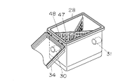
図8の外観図に示すように、リント捕獲箱28の構成は、上方に開口自在に蓋体34を配し、内方に格子状の捕獲部48を有する糸屑捕獲用のリントフィルター47を両対角線上にリント補修箱28より着脱可能に配設し、掃除を容易に行えるようにしていた。
しかしながら、前記従来の構成では、リント捕獲箱28は入水口30の対面側に出水口31を設けて、2本の排水ホース44、45の途中に接続配置されていたため、リント捕獲箱28は洗濯機外箱42の側面の奥に設置されるので、回収したリントを除去する作業が困難であった。
However, in the above-described conventional configuration, the lint capturing
また、リントフィルター47は両対角線上に間仕切り状に設置し、リントを引っ掛けて捕獲する構成にしているため、掃除をする場合にリントフィルター47を持ち上げると、リントの一部がリント捕獲箱28内底に残留してしまう課題や、リント捕獲箱28の底部に残水した部分にリントが常に浸漬しているため、リントが濡れた状態であり、手入れがしにくいなどの課題や、リントが堆積しリントフィルター47の目詰まりが生じると、通水路が狭くなり排水時間が長くなるために、洗濯時間が長くなるなどの不具合や、最悪の場合は、排水異常を発生するという課題があった。
Further, since the
本発明は、上記従来の課題を解決するもので、リント除去作業がしやすく、リントが堆積しリントフィルターの目詰まりが発生した場合でも通水路は遮断されることなく排水することができ、排水時間が長くなったり、排水異常が発生したりすることを防止する洗濯機を提供することを目的としている。 The present invention solves the above-mentioned conventional problems, and lint removal work is easy, and even when lint accumulates and clogging of the lint filter occurs, the water passage can be drained without being blocked. It is an object of the present invention to provide a washing machine that prevents the time from becoming longer and the occurrence of abnormal drainage.
前記従来の課題を解決するために、本発明の洗濯機は、一端が前記水槽の内底部に連通して設けられ、他端が前記外箱より機外に導出された排水ホースと、この排水ホースの他端に通水可能に設けられ、蓋体を上方開口部に開閉可能に設け、側面に入水口および出水口を有する容器状のリント捕獲箱と、前記リント捕獲箱内部に通水中からリントを捕獲するリントフィルターとを備え、前記リントフィルターは、上端面が前記蓋体の内面と隙間を有するとともに、下端面が前記リント捕獲箱の底面と隙間を有して前記リント捕獲箱の内部を2つの部屋に仕切る仕切り壁と、前記仕切り壁と一体に形成され、前記入水口側の部屋の前記底面より所定寸法上方で前記底面を覆うように網目状に形成された網目部とで構成したものである。 In order to solve the above-described conventional problems, a washing machine of the present invention includes a drainage hose having one end connected to the inner bottom portion of the water tank and the other end led out of the machine from the outer box, and the drainage Provided at the other end of the hose so that water can pass through, and a lid is provided at the upper opening so as to be openable and closable, and has a water inlet and a water outlet on the side surface. A lint filter that captures lint, and the lint filter has a gap between the upper end surface and the inner surface of the lid, and a lower end surface that has a gap between the bottom surface of the lint capture box and the inside of the lint capture box. A partition wall that divides the wall into two rooms, and a mesh part that is formed integrally with the partition wall and formed in a mesh shape so as to cover the bottom surface above the bottom surface of the room on the water inlet side by a predetermined dimension. It is a thing.
これにより、リントが堆積しリントフィルターの目詰まりが発生した場合でも通水路は遮断されることなく排水することができ、排水時間が長くなったり、排水異常が発生したりすることを防止することができる。 As a result, even if lint accumulates and clogging of the lint filter occurs, the water channel can be drained without being blocked, preventing drainage time from increasing and drainage abnormalities from occurring. Can do.
本発明の洗濯機は、リント除去の作業性を大幅に向上させ、さらにリントフィルターの目詰まりによる不具合を防止することができる。 The washing machine of the present invention can greatly improve the workability of lint removal and can further prevent problems due to clogging of the lint filter.
第1の発明は、洗濯機外箱内に収められた水槽と、前記水槽内に回転可能に設けた洗濯槽と、一端が前記水槽の内底部に連通して設けられ、他端が前記外箱より機外に導出された排水ホースと、この排水ホースの他端に通水可能に設けられ、蓋体を上方開口部に開閉可能に設け、側面に入水口および出水口を有する容器状のリント捕獲箱と、前記リント捕獲箱内部に通水中からリントを捕獲するリントフィルターとを備え、前記リントフィルターは、上端面が前記蓋体の内面と隙間を有するとともに、下端面が前記リント捕獲箱の底面と隙間を有して前記リント捕獲箱の内部を2つの部屋に仕切る仕切り壁と、前記仕切り壁と一体に形成され、前記入水口側の部屋の前記底面より所定寸法上方で前記底面を覆うように網目状に形成された網目部とで構成したことにより、リントが堆積しリントフィルターの目詰まりが発生した場合でも通水路は遮断されることなく排水することができ、排水時間が長くなったり、排水異常が発生したりすることを防止することができる。 According to a first aspect of the present invention, there is provided a water tub housed in an outer box of a washing machine, a washing tub rotatably provided in the water tub, one end provided in communication with an inner bottom portion of the water tub, and the other end A drainage hose led out of the machine from the box, and provided at the other end of the drainage hose so that water can pass through, a lid is provided at the upper opening so as to be openable and closable, and has a water inlet and a water outlet on the side. A lint capture box; and a lint filter that captures lint from running water inside the lint capture box. The lint filter has a gap between an upper end surface and an inner surface of the lid, and a lower end surface of the lint capture box. A partition wall that divides the interior of the lint capture box into two rooms with a gap between the bottom surface of the water inlet and the partition wall, and is formed integrally with the partition wall, and the bottom surface is formed above the bottom surface of the room on the inlet side by a predetermined dimension. Mesh formed in a mesh shape to cover Even if lint accumulates and the lint filter is clogged, the water passage can be drained without being blocked, draining time becomes longer, or drainage abnormality occurs. Can be prevented.
第2の発明は、特に第1の発明のリントフィルターは、網目部を略階段状に形成したことにより、捕獲面積および排水有効面積を増やし、早期に目詰まりが発生してしまうことを防止し、リントフィルターの掃除回数を削減することができる。 In the second invention, in particular, the lint filter of the first invention increases the capture area and the effective drainage area by forming the mesh portion in a substantially step shape, and prevents clogging from occurring at an early stage. The number of times of cleaning the lint filter can be reduced.
第3の発明は、特に第2の発明のリントフィルターは、網目部を略階段状に形成し、各段部をつなぐ縦壁部にも水抜き穴を設けたことにより、さらに排水有効面積を増やすことができ、早期に目詰まりが発生してしまうことを防止することができる。 In the third invention, in particular, the lint filter according to the second invention has a mesh portion formed substantially in a step shape, and a drainage hole is provided in a vertical wall portion connecting each step portion, thereby further increasing the effective drainage area. It can be increased and clogging can be prevented from occurring at an early stage.
第4の発明は、特に第1〜3のいずれか1つの発明のリントフィルターは、網目の大きさを5mm〜7mmの大きさに設定したことにより、排水口側にリントが流れ出る量を極力減らすと共に、容易に目詰まりが発生する課題を防止することができる。 In the fourth invention, in particular, the lint filter of any one of the first to third inventions reduces the amount of lint flowing out to the drain outlet side by setting the mesh size to 5 mm to 7 mm. At the same time, it is possible to prevent a problem that clogging easily occurs.
第5の発明は、特に第1〜4のいずれか1つの発明のリントフィルターは、仕切り壁と一体に形成され、前記仕切り壁の網目部とは反対側にリント捕獲箱の内壁面に当接するリブを設けたことにより、リント捕獲箱内へフィルター設置する際のガタツキを防止することができる。 According to a fifth aspect of the present invention, in particular, the lint filter according to any one of the first to fourth aspects of the present invention is formed integrally with the partition wall and abuts against the inner wall surface of the lint capturing box on the opposite side of the mesh portion of the partition wall. By providing the rib, it is possible to prevent rattling when the filter is installed in the lint capturing box.
第6の発明は、リント捕獲箱の内壁側面に略凹字形状となる嵌合部を設け、リントフィルターは、上端面が蓋体の内面と隙間を有するとともに、下端面が前記リント捕獲箱の底面と隙間を有して前記リント捕獲箱の内部を2つの部屋に仕切る仕切り壁と、前記リントフィルターの前記仕切り壁の端部が前記リント捕獲箱の嵌合部に遊嵌し、さらに前記仕切り壁と一体に形成され、前記入水口側の部屋の前記底面より所定寸法上方で前記底面を覆うように網目状に形成された網目部とで構成したことにより、フィルター挿入の操作性を向上し、さらにリント捕獲箱内へフィルター設置する際のガタツキを防止することができる。 According to a sixth aspect of the present invention, a fitting portion having a substantially concave shape is provided on the inner wall side surface of the lint capture box, and the lint filter has a gap between the upper end surface and the inner surface of the lid, and a lower end surface of the lint capture box. A partition wall that divides the interior of the lint capture box into two chambers with a bottom surface and a gap; and an end of the partition wall of the lint filter is loosely fitted to a fitting portion of the lint capture box; It is formed integrally with the wall, and has a mesh portion formed in a mesh shape so as to cover the bottom surface above the bottom surface of the room on the water inlet side by a predetermined dimension, thereby improving the operability of filter insertion. Furthermore, rattling when the filter is installed in the lint capture box can be prevented.
第7の発明は、特に第1〜6のいずれか1つの発明のリントフィルターは、網目部とリブとを異なる高さに構成し、リント捕獲箱の内壁底面に前記リントフィルターの網目部を載置支持するための凸状リブを複数個設けたことにより、リント捕獲箱内へフィルター設置する際のガタツキを防止することができ、またリントフィルターの逆挿入も防止することができる。 According to a seventh aspect of the present invention, in the lint filter according to any one of the first to sixth aspects, the mesh portion and the rib are formed at different heights, and the mesh portion of the lint filter is mounted on the bottom surface of the inner wall of the lint capturing box. By providing a plurality of convex ribs for placing and supporting, it is possible to prevent rattling when the filter is installed in the lint capture box and to prevent reverse insertion of the lint filter.
第8の発明は、特に第1〜7のいずれか1つの発明のリントフィルターは、網目部の外周部に壁状リブを設けたことにより、リント捕獲箱からリントフィルターを取り出すときに、フィルターで捕獲された異物が落下しないようにすることができる。 According to an eighth aspect of the present invention, in particular, the lint filter according to any one of the first to seventh aspects is provided with a wall-like rib on the outer periphery of the mesh portion, so that when the lint filter is taken out from the lint capture box, It is possible to prevent the captured foreign matter from falling.
第9の発明は、リント捕獲箱の同一の側面に入水口と出水口を設けたことにより、洗濯機外箱の前面にりんと捕獲箱とその蓋体の開閉機構が設置でき、回収したリントを除去する作業が容易になる。 According to the ninth aspect of the present invention, a water inlet and a water outlet are provided on the same side surface of the lint capture box, so that an opening and closing mechanism for the phosphorus, the capture box and its lid can be installed on the front surface of the outer box of the washing machine. The removal work becomes easy.
以下、本発明の実施の形態について、図面を参照しながら説明する。なお、この実施の形態によって本発明が限定されるものではない。 Hereinafter, embodiments of the present invention will be described with reference to the drawings. Note that the present invention is not limited to the embodiments.
(実施の形態1)
図1は、本発明の実施の形態1における洗濯機の要部構成図、図2は、同洗濯機のリント捕獲箱の外観構成矢視図、図3は、同洗濯機のリントフィルターの(a)平面図、(b)横側面図、(c)右側面図を示し、図4は、リント捕獲箱とリントフィルターの断面図を示す。
(Embodiment 1)
FIG. 1 is a main part configuration diagram of a washing machine according to Embodiment 1 of the present invention, FIG. 2 is an external configuration arrow view of a lint capture box of the washing machine, and FIG. 3 is a lint filter ( FIG. 4 shows a sectional view of a lint capture box and a lint filter.
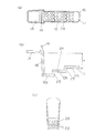
図1において、洗濯機外箱1内部に収められた水槽2と、水槽2内に回転可能に設けた洗濯槽3とを備え、この洗濯槽3内に衣類を投入して洗濯運転を行う。
In FIG. 1, a
水槽2内部の洗濯水を機外に排出する排水ホース4は、一端が水槽2の内底部2aに連通し、他端はリント捕獲箱6の入水口7に通水可能に接続される。
One end of the
リント捕獲箱6は、入水口7と同一面に構成した出水口8に第2の排水ホース10を接続し、リント捕獲箱6内部でリント、異物等を除去した排水を出水側排水ホース10から設置床面側の排水口10aに排出するように構成し、また内部に溜ったリント等を取り出し排除する作業の為の蓋体5を上部に開閉自在に配する。ここで、同一面に構成した入水口7と出水口8との位置関係は、入水口7が出水口8より上方に配置すると共に、出水口8は、床面20に近接するように配置する。
The
また、リント捕獲箱6の蓋体5を開放する操作用の開閉操作機構9は、洗濯機外箱1の前方の使用者操作側1a側に構成する。
An opening / closing operation mechanism 9 for opening the
図2の外観構成図に示すように、リント捕獲箱6は、内部にリント捕獲用のリントフィルター11を着脱可能に装着し、入水口7と同一側面に出水口8を有し、入水口7および出水口8を構成したリント捕獲箱6上方に蓋体5を開閉自在に軸支する蝶番機構17を有する。従って、蓋体5を開閉する操作用の開閉操作機構9は、入水口7、出水口8および蝶番機構17の対面側に配置となる。
As shown in the external configuration diagram of FIG. 2, the
図3(a)の平面図に示すように、リントフィルター11は、通水中からリントを捕獲する網目部12と、仕切り壁14及び、リブ13で構成され、仕切り壁14の位置は、網目部12とリブ13の間に構成する。
As shown in the plan view of FIG. 3 (a), the
また、(b)の横側面図に示すように、網目部12は、複数の高さを有する段部12a、12b、12cと、最も高い位置の段部12cより、更に上方の位置の高さ寸法Hにリブ13を構成する。
Further, as shown in the lateral side view of (b), the
網目部12、即ち段部12a、12b、12cには一辺約5mmの格子穴24を多数設けてリントの捕獲部とし、かつ、図3(c)の右側面図にも示すように段部をつなぐ縦壁部23にも水抜き穴22を形成する。
The
網目部12とリブ13の間を接続する縦壁18に上部には、リント堰き止め用リブであり、かつリントフィルター11を、リント捕獲箱6からの着脱用の取っ手となる仕切り壁14を設けている。また、網目部12の外周部には壁状リブ16を形成している。
A
図4の組み立て状態の断面図に示すように、リントフィルター11はリント捕獲箱6の内壁底部に設けた複数個の凸状リブ15a、15b、15cに、段部12a、12b、12cをそれぞれ載せる形でリント捕獲箱6内に収納され、リブ13の周縁部下面は、リント捕獲箱6の内側壁に形成した側壁リブ19の上端に載置して位置決めとする。
As shown in the sectional view of the assembled state in FIG. 4, the
段部12a、12b、12cの最も低い高さにある段部12aは、リント捕獲箱6の内底部から寸法Mの隙間(床面から寸法N)を形成し通水路25を構成する。
The
入水口7から流入した洗濯水は、リントフィルター11の上方の空間部21から、段部12a、12b、12cの網目および縦壁部23の水抜き穴22を通過する際に捕獲され、リントを除去された洗濯水は、出水口8より排出される。
The washing water flowing in from the
リントフィルター11の、網目部12の最も高い位置の段部12cの先端11aの、リント捕獲箱6の設置面20からの高さKは、入水口7の内径下面高さaと出水口8の内径上面高さbとの中間位置、即ち、a>K>bとなるように構成している。
The height K of the tip 11a of the
床面20に近接するように配置した出水口8の高さ位置は、その内径下面高さcは出来るだけ小さく設定し、かつ、既述の最も低い高さの段部12aの床面からの寸法Nに対し、c<Nとなるように形成する。
As for the height position of the
また、取っ手となる仕切り壁14の先端は、蓋体5に隙間Sで近接させ、かつリント補修箱6の上縁部6aより寸法微小隙間Tだけ低く設定する。
Further, the tip of the
以上のように構成された洗濯機のリント捕獲手段について、以下その動作、作用を説明する。 About the lint capture means of the washing machine comprised as mentioned above, the operation | movement and an effect | action are demonstrated below.
まず、リント捕獲箱6は、同一面に入水口7と出水口8を有することにより、リント捕獲箱6は第1の排水ホース4の先端に配置することができ、また、入水口7および出水口8の対面側に配した蓋体5の開閉操作機構9を設けることにより、リント捕獲箱6のリント除去の作業を、洗濯機外箱1の前方の使用者操作側1a側に構成できるので操作性が向上する。
First, the
また、水槽2内から排出される排出液は水槽2の内底部2aを通り、第1の排水ホース4を通って入水口7からリント捕獲箱6内に導水され出水口8側から排出されるが、この時、リントフィルター11の先端11aの高さ位置を入水口7と出水口8との間の高さに配設しているため、入水口7から出水口8へ流れる排出液は確実にリントフィルター11の網目部12の段部12a、12b、12cの格子穴24および縦壁部23の水抜き穴22を通過する際に、排水液内に含まれる排出リントや異物等をリントフィルター11で確実に捕獲することができる。
Further, the discharged liquid discharged from the
また、リント捕獲箱6内の残水は、出水口8の内径下面高さcよりも高い位置にある排水液は、出水口8からリント捕獲箱6外に排出されるため、出水口8の内径上面高さc以下の水位までとなり、出水口8の内径下面高さcよりも高い位置に配設している網目部12で捕獲したリントは、リント捕獲6内の残水した部分に浸ることなく確実に水切りをすることができ、リントフィルター11を取り出して掃除をする際、水が滴ることもなく簡単にお手入れをするができる。
Moreover, since the waste water in the
また、リントや異物は、蓋体5とリント捕獲箱6と網目部12と仕切り壁14とで形成される空間21に捕獲され、空間21がリントや異物で満たされたり、リントフィルターの目詰まりが発生した場合、排水液は仕切り壁14の上部の隙間Sからオーバーフローしてリブ13に流れ出て、リントフィルター11の下方の隙間Mの通水路25を通過するため、通水路は遮断されることなく出水口8から排水することができ、排水時間が長くなったり、排水異常が発生したりすることを防止することができる。
Also, lint and foreign matter are captured in a
さらに、網目部12の格子穴24を略階段状の段部12a、12b、12cの格子穴24および、縦壁部23にも水抜き穴22を構成にすることで網目の表面積が増加し、排水液が通過する排水有効面積も同時に増えるので、早期に目詰まりが発生して排水ができなくなることを防止し、リントフィルター掃除の頻度を低減することができる。
Furthermore, the surface area of the mesh is increased by configuring the lattice holes 24 of the
リントフィルター11に設けた仕切り壁14の高さは、寸法微小隙間Tだけ低く構成し、リント捕獲箱6とほぼ同じ高さの設定とすることで、掃除するときにフィルターを手で摘んで取り上げるなどの着脱操作が容易となり、作業性を向上させることができ、また、排水時にリント捕獲箱6内に排水液で満たされた状態になったとき、浮力によりリントフィルター11が浮き上がろうとするが、仕切り壁14が蓋5に当たることで防止することができる。
The height of the
網目部12の網目の大きさは略5mm〜7mmの大きさにすることで、リントや異物が排水口側に流れ出る量を極力減らすと同時に、容易に目詰まりが発生する課題も防止することができ、網目部12の外周部に壁状リブ16を設けることにより、フィルター掃除するときなど、リント捕獲箱からリントフィルターを取り出すときに、フィルターで捕獲された異物が落下しないようにすることができ、さらにフィルター強度の向上も同時にできる。
By setting the mesh size of the
掃除後などリント捕獲箱6内にリントフィルター11をセットする時、リント捕獲箱6内の内壁底面に設けた複数個の凸状リブ15a、15b、15cで段部12a、12b、12cを支持する構成にし、さらにリブ13の高さを網目部12よりもH寸法だけ高い位置に設定することで、前後のガタツキを防止し、安定してセットすることができ、また、リントフィルター11の天地を逆設置や、斜めに設置するなど誤った取り付けをしようとした場合は、凸状リブ15a、15b、15cがリントフィルター11の一部に当たり蓋体5を閉めることができないようにし、フィルターの逆挿入防止もすることができる。
When the
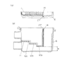
また、図5のリント捕獲箱とリントフィルターの取り付け状態の(a)上面図、(b)断面図に示すように、リント捕獲箱6の内壁側面に略凹字形状となる嵌合部26を設け、リントフィルター11の仕切り壁14の端部14aが、リント捕獲箱6の嵌合部26に遊嵌し、段部12a、12b、12cの最も低い高さにある段部12aは、リント捕獲箱6の内底部から寸法Mの隙間(床面から寸法N)を形成し通水路25を構成する。
Further, as shown in (a) top view and (b) cross-sectional view of the lint capture box and lint filter attached in FIG. 5, a
これにより、リントフィルター11をリント捕獲箱6にセットする際、嵌合部26にリントフィルター11の端部14aを合わせて挿入することで、前後のガタツキを防止し、さらに安定してセットすることができる。
Thereby, when setting the
また、図6のリント捕獲箱とリントフィルターの取り付け状態の(a)上面図、(b)断面図に示すような嵌合部27の形状でも同様の効果は得ることができる。
Further, the same effect can be obtained with the shape of the
また、本実施の形態で説明した、リント捕獲箱6の同一側面に入水口7と出水口8を有する等は単なる例示にすぎず、同一側面になくても特許請求の範囲の技術思想に基づいて本発明に包含されるものである。
Moreover, having the
以上のように、本発明にかかる洗濯機は、リント除去の作業性を大幅に向上させ、リントフィルターの目詰まりによる不具合を防止することが可能となるので、リント捕獲手段を備えた洗濯機等として有用である。 As described above, the washing machine according to the present invention greatly improves the workability of lint removal, and can prevent problems due to clogging of the lint filter. Useful as.
1 洗濯機外箱
2 水槽
2a 内底部
3 洗濯槽
4 排水ホース
5 蓋体
6 リント捕獲箱
7 入水口
8 出水口
11 リントフィルター
12 網目部
12a 段部
13 リブ
14 仕切り壁
15a 凸状リブ
16 壁状リブ
DESCRIPTION OF SYMBOLS 1 Washing machine
Claims (9)
Priority Applications (1)
| Application Number | Priority Date | Filing Date | Title |
|---|---|---|---|
| JP2008170075A JP4793411B2 (en) | 2008-06-30 | 2008-06-30 | Washing machine |
Applications Claiming Priority (1)
| Application Number | Priority Date | Filing Date | Title |
|---|---|---|---|
| JP2008170075A JP4793411B2 (en) | 2008-06-30 | 2008-06-30 | Washing machine |
Publications (2)
| Publication Number | Publication Date |
|---|---|
| JP2010005247A true JP2010005247A (en) | 2010-01-14 |
| JP4793411B2 JP4793411B2 (en) | 2011-10-12 |
Family
ID=41586400
Family Applications (1)
| Application Number | Title | Priority Date | Filing Date |
|---|---|---|---|
| JP2008170075A Active JP4793411B2 (en) | 2008-06-30 | 2008-06-30 | Washing machine |
Country Status (1)
| Country | Link |
|---|---|
| JP (1) | JP4793411B2 (en) |
Cited By (4)
| Publication number | Priority date | Publication date | Assignee | Title |
|---|---|---|---|---|
| DE102012220852A1 (en) | 2012-11-15 | 2014-05-15 | BSH Bosch und Siemens Hausgeräte GmbH | Filter arrangement for a laundry treatment machine |
| CN107142672A (en) * | 2017-07-06 | 2017-09-08 | 安徽金帅洗衣机有限公司 | A kind of stainless steel washing tube of semi-automatic rotary drum washing machine |
| JP2017189270A (en) * | 2016-04-12 | 2017-10-19 | 日立アプライアンス株式会社 | Washing machine |
| JP2018000784A (en) * | 2016-07-07 | 2018-01-11 | 株式会社テクノテック | Lint cotton collector |
-
2008
- 2008-06-30 JP JP2008170075A patent/JP4793411B2/en active Active
Cited By (6)
| Publication number | Priority date | Publication date | Assignee | Title |
|---|---|---|---|---|
| DE102012220852A1 (en) | 2012-11-15 | 2014-05-15 | BSH Bosch und Siemens Hausgeräte GmbH | Filter arrangement for a laundry treatment machine |
| WO2014075909A1 (en) | 2012-11-15 | 2014-05-22 | BSH Bosch und Siemens Hausgeräte GmbH | Filter system for a laundry treatment machine |
| JP2017189270A (en) * | 2016-04-12 | 2017-10-19 | 日立アプライアンス株式会社 | Washing machine |
| JP2018000784A (en) * | 2016-07-07 | 2018-01-11 | 株式会社テクノテック | Lint cotton collector |
| CN107142672A (en) * | 2017-07-06 | 2017-09-08 | 安徽金帅洗衣机有限公司 | A kind of stainless steel washing tube of semi-automatic rotary drum washing machine |
| CN107142672B (en) * | 2017-07-06 | 2019-02-22 | 安徽金帅洗衣机有限公司 | A kind of stainless steel washing tube of semi-automatic rotary drum washing machine |
Also Published As
| Publication number | Publication date |
|---|---|
| JP4793411B2 (en) | 2011-10-12 |
Similar Documents
| Publication | Publication Date | Title |
|---|---|---|
| KR101332286B1 (en) | Washing Machine | |
| JP2018143524A (en) | Washing machine | |
| JP2005319282A (en) | Washing machine having drain casing | |
| JP4740247B2 (en) | dishwasher | |
| JP2006223572A (en) | Washing machine | |
| KR101612804B1 (en) | Laundry treatment machine | |
| JP4793411B2 (en) | Washing machine | |
| JP4893717B2 (en) | Washing machine | |
| JP7376981B2 (en) | Filter device and washing machine | |
| KR20090024591A (en) | Garbage collecting apparatus of dish washer | |
| JP3910201B2 (en) | Washing machine | |
| KR100778688B1 (en) | A filtering device of fuzz at a drum washer | |
| WO2020039770A1 (en) | Washing machine | |
| JP2017144123A (en) | Washing machine | |
| JP4844604B2 (en) | Washing machine | |
| KR101620445B1 (en) | A laundry treatment machine | |
| EP2405050A1 (en) | Washing machine | |
| KR20070090397A (en) | Washing machine's filter | |
| KR20080088175A (en) | Washing machine | |
| JP4504574B2 (en) | Wash water outflow mechanism in the wash water tank | |
| JP7071402B2 (en) | Washing machine | |
| JP3988558B2 (en) | Dishwasher leftover collection equipment | |
| CN220224664U (en) | Washing machine | |
| WO2022041892A1 (en) | Washing machine | |
| KR100701171B1 (en) | Lifter of drum type washing machine |
Legal Events
| Date | Code | Title | Description |
|---|---|---|---|
| A977 | Report on retrieval |
Free format text: JAPANESE INTERMEDIATE CODE: A971007 Effective date: 20110601 |
|
| TRDD | Decision of grant or rejection written | ||
| A01 | Written decision to grant a patent or to grant a registration (utility model) |
Free format text: JAPANESE INTERMEDIATE CODE: A01 Effective date: 20110628 |
|
| A01 | Written decision to grant a patent or to grant a registration (utility model) |
Free format text: JAPANESE INTERMEDIATE CODE: A01 |
|
| A61 | First payment of annual fees (during grant procedure) |
Free format text: JAPANESE INTERMEDIATE CODE: A61 Effective date: 20110711 |
|
| R151 | Written notification of patent or utility model registration |
Ref document number: 4793411 Country of ref document: JP Free format text: JAPANESE INTERMEDIATE CODE: R151 |
|
| FPAY | Renewal fee payment (event date is renewal date of database) |
Free format text: PAYMENT UNTIL: 20140805 Year of fee payment: 3 |