JP7621613B2 - Power supply device and power supply system - Google Patents
Power supply device and power supply system Download PDFInfo
- Publication number
- JP7621613B2 JP7621613B2 JP2021033368A JP2021033368A JP7621613B2 JP 7621613 B2 JP7621613 B2 JP 7621613B2 JP 2021033368 A JP2021033368 A JP 2021033368A JP 2021033368 A JP2021033368 A JP 2021033368A JP 7621613 B2 JP7621613 B2 JP 7621613B2
- Authority
- JP
- Japan
- Prior art keywords
- power supply
- coil
- power
- magnetic body
- receiving coil
- Prior art date
- Legal status (The legal status is an assumption and is not a legal conclusion. Google has not performed a legal analysis and makes no representation as to the accuracy of the status listed.)
- Active
Links
Images

Classifications
-
- H—ELECTRICITY
- H02—GENERATION; CONVERSION OR DISTRIBUTION OF ELECTRIC POWER
- H02J—ELECTRIC POWER NETWORKS; CIRCUIT ARRANGEMENTS OR SYSTEMS FOR SUPPLYING OR DISTRIBUTING ELECTRIC POWER; SYSTEMS FOR STORING ELECTRIC ENERGY
- H02J50/00—Circuit arrangements or systems for wireless supply or distribution of electric power
- H02J50/10—Circuit arrangements or systems for wireless supply or distribution of electric power using inductive coupling
- H02J50/12—Circuit arrangements or systems for wireless supply or distribution of electric power using inductive coupling of the resonant type
-
- B—PERFORMING OPERATIONS; TRANSPORTING
- B60—VEHICLES IN GENERAL
- B60L—PROPULSION OF ELECTRICALLY-PROPELLED VEHICLES; SUPPLYING ELECTRIC POWER FOR AUXILIARY EQUIPMENT OF ELECTRICALLY-PROPELLED VEHICLES; ELECTRODYNAMIC BRAKE SYSTEMS FOR VEHICLES IN GENERAL; MAGNETIC SUSPENSION OR LEVITATION FOR VEHICLES; MONITORING OPERATING VARIABLES OF ELECTRICALLY-PROPELLED VEHICLES; ELECTRIC SAFETY DEVICES FOR ELECTRICALLY-PROPELLED VEHICLES
- B60L53/00—Methods of charging batteries, specially adapted for electric vehicles; Charging stations or on-board charging equipment therefor; Exchange of energy storage elements in electric vehicles
- B60L53/10—Methods of charging batteries, specially adapted for electric vehicles; Charging stations or on-board charging equipment therefor; Exchange of energy storage elements in electric vehicles characterised by the energy transfer between the charging station and the vehicle
- B60L53/12—Inductive energy transfer
-
- H—ELECTRICITY
- H01—ELECTRIC ELEMENTS
- H01F—MAGNETS; INDUCTANCES; TRANSFORMERS; SELECTION OF MATERIALS FOR THEIR MAGNETIC PROPERTIES
- H01F38/00—Adaptations of transformers or inductances for specific applications or functions
- H01F38/14—Inductive couplings
-
- H—ELECTRICITY
- H02—GENERATION; CONVERSION OR DISTRIBUTION OF ELECTRIC POWER
- H02J—ELECTRIC POWER NETWORKS; CIRCUIT ARRANGEMENTS OR SYSTEMS FOR SUPPLYING OR DISTRIBUTING ELECTRIC POWER; SYSTEMS FOR STORING ELECTRIC ENERGY
- H02J50/00—Circuit arrangements or systems for wireless supply or distribution of electric power
- H02J50/005—Mechanical details of housing or structure aiming to accommodate the power transfer means, e.g. mechanical integration of coils, antennas or transducers into emitting or receiving devices
-
- H—ELECTRICITY
- H02—GENERATION; CONVERSION OR DISTRIBUTION OF ELECTRIC POWER
- H02J—ELECTRIC POWER NETWORKS; CIRCUIT ARRANGEMENTS OR SYSTEMS FOR SUPPLYING OR DISTRIBUTING ELECTRIC POWER; SYSTEMS FOR STORING ELECTRIC ENERGY
- H02J50/00—Circuit arrangements or systems for wireless supply or distribution of electric power
- H02J50/40—Circuit arrangements or systems for wireless supply or distribution of electric power using two or more transmitting or receiving devices
- H02J50/402—Circuit arrangements or systems for wireless supply or distribution of electric power using two or more transmitting or receiving devices the two or more transmitting or the two or more receiving devices being integrated in the same unit, e.g. power mats with several coils or antennas with several sub-antennas
-
- H—ELECTRICITY
- H02—GENERATION; CONVERSION OR DISTRIBUTION OF ELECTRIC POWER
- H02J—ELECTRIC POWER NETWORKS; CIRCUIT ARRANGEMENTS OR SYSTEMS FOR SUPPLYING OR DISTRIBUTING ELECTRIC POWER; SYSTEMS FOR STORING ELECTRIC ENERGY
- H02J50/00—Circuit arrangements or systems for wireless supply or distribution of electric power
- H02J50/90—Circuit arrangements or systems for wireless supply or distribution of electric power involving detection or optimisation of position, e.g. alignment
-
- B—PERFORMING OPERATIONS; TRANSPORTING
- B60—VEHICLES IN GENERAL
- B60L—PROPULSION OF ELECTRICALLY-PROPELLED VEHICLES; SUPPLYING ELECTRIC POWER FOR AUXILIARY EQUIPMENT OF ELECTRICALLY-PROPELLED VEHICLES; ELECTRODYNAMIC BRAKE SYSTEMS FOR VEHICLES IN GENERAL; MAGNETIC SUSPENSION OR LEVITATION FOR VEHICLES; MONITORING OPERATING VARIABLES OF ELECTRICALLY-PROPELLED VEHICLES; ELECTRIC SAFETY DEVICES FOR ELECTRICALLY-PROPELLED VEHICLES
- B60L2200/00—Type of vehicles
- B60L2200/10—Air crafts
-
- H—ELECTRICITY
- H02—GENERATION; CONVERSION OR DISTRIBUTION OF ELECTRIC POWER
- H02J—ELECTRIC POWER NETWORKS; CIRCUIT ARRANGEMENTS OR SYSTEMS FOR SUPPLYING OR DISTRIBUTING ELECTRIC POWER; SYSTEMS FOR STORING ELECTRIC ENERGY
- H02J2105/00—Networks for supplying or distributing electric power characterised by their spatial reach or by the load
- H02J2105/30—Networks for supplying or distributing electric power characterised by their spatial reach or by the load the load networks being external to vehicles, i.e. exchanging power with vehicles
- H02J2105/32—Networks for supplying or distributing electric power characterised by their spatial reach or by the load the load networks being external to vehicles, i.e. exchanging power with vehicles for aircrafts
-
- Y—GENERAL TAGGING OF NEW TECHNOLOGICAL DEVELOPMENTS; GENERAL TAGGING OF CROSS-SECTIONAL TECHNOLOGIES SPANNING OVER SEVERAL SECTIONS OF THE IPC; TECHNICAL SUBJECTS COVERED BY FORMER USPC CROSS-REFERENCE ART COLLECTIONS [XRACs] AND DIGESTS
- Y02—TECHNOLOGIES OR APPLICATIONS FOR MITIGATION OR ADAPTATION AGAINST CLIMATE CHANGE
- Y02T—CLIMATE CHANGE MITIGATION TECHNOLOGIES RELATED TO TRANSPORTATION
- Y02T10/00—Road transport of goods or passengers
- Y02T10/60—Other road transportation technologies with climate change mitigation effect
- Y02T10/70—Energy storage systems for electromobility, e.g. batteries
-
- Y—GENERAL TAGGING OF NEW TECHNOLOGICAL DEVELOPMENTS; GENERAL TAGGING OF CROSS-SECTIONAL TECHNOLOGIES SPANNING OVER SEVERAL SECTIONS OF THE IPC; TECHNICAL SUBJECTS COVERED BY FORMER USPC CROSS-REFERENCE ART COLLECTIONS [XRACs] AND DIGESTS
- Y02—TECHNOLOGIES OR APPLICATIONS FOR MITIGATION OR ADAPTATION AGAINST CLIMATE CHANGE
- Y02T—CLIMATE CHANGE MITIGATION TECHNOLOGIES RELATED TO TRANSPORTATION
- Y02T10/00—Road transport of goods or passengers
- Y02T10/60—Other road transportation technologies with climate change mitigation effect
- Y02T10/7072—Electromobility specific charging systems or methods for batteries, ultracapacitors, supercapacitors or double-layer capacitors
-
- Y—GENERAL TAGGING OF NEW TECHNOLOGICAL DEVELOPMENTS; GENERAL TAGGING OF CROSS-SECTIONAL TECHNOLOGIES SPANNING OVER SEVERAL SECTIONS OF THE IPC; TECHNICAL SUBJECTS COVERED BY FORMER USPC CROSS-REFERENCE ART COLLECTIONS [XRACs] AND DIGESTS
- Y02—TECHNOLOGIES OR APPLICATIONS FOR MITIGATION OR ADAPTATION AGAINST CLIMATE CHANGE
- Y02T—CLIMATE CHANGE MITIGATION TECHNOLOGIES RELATED TO TRANSPORTATION
- Y02T90/00—Enabling technologies or technologies with a potential or indirect contribution to GHG emissions mitigation
- Y02T90/10—Technologies relating to charging of electric vehicles
- Y02T90/14—Plug-in electric vehicles
Landscapes
- Engineering & Computer Science (AREA)
- Power Engineering (AREA)
- Computer Networks & Wireless Communication (AREA)
- Transportation (AREA)
- Mechanical Engineering (AREA)
- Charge And Discharge Circuits For Batteries Or The Like (AREA)
Description
本発明は、給電装置及び給電システムに関する。 The present invention relates to a power supply device and a power supply system.
従来、給電装置及び給電システムとして、例えば、特開2017-135880号公報に記載されるように、マルチコプターを給電対象とし、このマルチコプターに対し給電を行うシステムが知られている。このシステムは、送電コイルを備えたステーションにマルチコプターを着陸させ、ステーション側の送電コイルとマルチコプター側の受電コイルを磁気結合させて、マルチコプターに対し給電を行う。 Conventionally, as a power supply device and power supply system, for example, a system that supplies power to a multicopter as a power supply target is known, as described in JP 2017-135880 A. In this system, the multicopter lands on a station equipped with a power transmission coil, and the power transmission coil on the station side is magnetically coupled with the power receiving coil on the multicopter side to supply power to the multicopter.
このような給電を行うにあたり、給電対象には受電コイルを搭載する必要があり、その他の部品を搭載するとなると、給電対象の重量が増加する。例えば、給電対象が移動体の場合に移動体の重量は軽い方がよいし、給電対象が持ち運べるデバイスである場合などでも軽量化を図ることが望ましい。 To supply power in this way, the target to be powered must be equipped with a receiving coil, and if other components are to be installed, the weight of the target to be powered will increase. For example, if the target to be powered is a moving object, it is better for the moving object to be light, and even if the target to be powered is a portable device, it is desirable to reduce the weight.
そこで、給電対象の軽量化が図れる給電装置及び給電システムの開発が望まれている。 Therefore, there is a need to develop a power supply device and power supply system that can reduce the weight of the power supply target.
本開示の一態様に係る給電装置は、給電対象へワイヤレス給電を行う給電装置において、給電対象を給電位置に位置させて給電対象への給電を行うための給電部と、給電部に設けられ、通電により磁界を発生させる送電コイルと、給電部に設けられ送電コイルから発生される磁界を受けて送電コイルと磁気結合し給電対象が給電位置に位置している場合に給電対象に設けられる受電コイルと磁気結合する第三コイルと、給電部に設けられ第三コイルと受電コイルの磁気結合に用いられる磁性体と備えて構成されている。この給電装置によれば、給電部に第三コイルを設けることにより、この第三コイルを介して送電コイルと受電コイルを磁気結合させることができる。また、第三コイルと受電コイルの磁気結合させる磁性体を備えることにより、第三コイルと受電コイルの磁気結合を高めて給電効率の低下を抑制することができる。このため、給電効率の低下を抑制しつつ、受電コイルの背面側の磁性体の設置を省略することができる。従って、給電対象に磁気結合のための磁性体の設置が不要となり、給電対象の軽量化を図ることができる。 The power supply device according to one aspect of the present disclosure is a power supply device that wirelessly supplies power to a power supply target, and is configured to include a power supply unit for positioning the power supply target at a power supply position and supplying power to the power supply target, a power transmission coil that is provided in the power supply unit and generates a magnetic field when current is passed through it, a third coil that is provided in the power supply unit and magnetically couples with the power transmission coil when it receives the magnetic field generated by the power transmission coil and magnetically couples with the power receiving coil provided in the power supply target when the power supply target is located at the power supply position, and a magnetic body that is provided in the power supply unit and used for magnetic coupling between the third coil and the power receiving coil. According to this power supply device, by providing a third coil in the power supply unit, the power transmission coil and the power receiving coil can be magnetically coupled via this third coil. In addition, by providing a magnetic body that magnetically couples the third coil and the power receiving coil, the magnetic coupling between the third coil and the power receiving coil can be increased and a decrease in power supply efficiency can be suppressed. Therefore, it is possible to omit the installation of a magnetic body on the back side of the power receiving coil while suppressing a decrease in power supply efficiency. Therefore, it is not necessary to install a magnetic body for magnetic coupling on the power supply target, and the weight of the power supply target can be reduced.
また、本開示の一態様に係る給電装置において、受電コイルは、第三コイルより小さく形成され、給電対象が給電位置に位置した場合に第三コイルの内周側に配置されていてもよい。この場合、給電対象が給電位置に位置した場合に受電コイルが第三コイルの内周側に配置されることにより、第三コイルと受電コイルの磁気結合を強めることができ、給電効率を高めることができる。また、第三コイルより受電コイルを小さく構成することができ、受電コイルを搭載する給電対象の軽量化を図ることができる。 In addition, in a power supply device according to one aspect of the present disclosure, the power receiving coil may be formed smaller than the third coil and may be disposed on the inner circumference side of the third coil when the power supply target is located at the power supply position. In this case, by disposing the power receiving coil on the inner circumference side of the third coil when the power supply target is located at the power supply position, it is possible to strengthen the magnetic coupling between the third coil and the power receiving coil, and to improve the power supply efficiency. In addition, it is possible to configure the power receiving coil to be smaller than the third coil, and it is possible to reduce the weight of the power supply target on which the power receiving coil is mounted.
また、本開示の一態様に係る給電装置において、送電コイル及び第三コイルは同軸状に設けられ、給電対象が給電位置に位置した場合に受電コイル、送電コイル及び第三コイルが同軸状に配置されていてもよい。この場合、給電対象が給電位置に位置した場合に受電コイル、送電コイル及び第三コイルが同軸状に配置されるため、第三コイルを介して受電コイルと送電コイルを強く磁気結合させることができ、給電効率を高めることができる。 In addition, in a power supply device according to one aspect of the present disclosure, the power transmission coil and the third coil may be provided coaxially, and when the power supply target is located at the power supply position, the power receiving coil, the power transmission coil, and the third coil may be arranged coaxially. In this case, when the power supply target is located at the power supply position, the power receiving coil, the power transmission coil, and the third coil are arranged coaxially, so that the power receiving coil and the power transmission coil can be strongly magnetically coupled via the third coil, thereby improving the power supply efficiency.
また、本開示の一態様に係る給電装置において、給電対象は、飛行体であってもよい。この場合、給電対象である飛行体の軽量化を図ることができる。 In addition, in the power supply device according to one aspect of the present disclosure, the power supply target may be an aircraft. In this case, it is possible to reduce the weight of the aircraft that is the power supply target.
本開示の一態様に係る給電システムは、給電対象へワイヤレス給電を行う給電システムにおいて、給電対象に設けられる受電コイルと、給電対象を給電位置に位置させて給電対象への給電を行うための給電部と、給電部に設けられ、通電により磁界を発生させる送電コイルと、給電部に設けられ送電コイルから発生される磁界を受けて送電コイルと磁気結合し給電対象が給電位置に位置している場合に受電コイルと磁気結合する第三コイルと、給電部に設けられ第三コイルと受電コイルの磁気結合に用いられる磁性体とを備えて構成されている。この給電システムによれば、給電部に第三コイルを設けることにより、この第三コイルを介して送電コイルと受電コイルを磁気結合させることができる。また、第三コイルと受電コイルの磁気結合させる磁性体を備えることにより、第三コイルと受電コイルの磁気結合を高めて給電効率の低下を抑制することができる。このため、給電効率の低下を抑制しつつ、受電コイルの背面側の磁性体の設置を省略することができる。従って、給電対象に磁気結合のための磁性体の設置が不要となり、給電対象の軽量化を図ることができる。 A power supply system according to one aspect of the present disclosure is a power supply system that wirelessly supplies power to a power supply target, and is configured to include a power receiving coil provided in the power supply target, a power supply unit for positioning the power supply target at a power supply position and supplying power to the power supply target, a power transmission coil provided in the power supply unit and generating a magnetic field by energization, a third coil provided in the power supply unit and magnetically coupled to the power transmission coil when receiving a magnetic field generated by the power transmission coil and magnetically coupled to the power receiving coil when the power supply target is located at the power supply position, and a magnetic body provided in the power supply unit and used for magnetic coupling of the third coil and the power receiving coil. According to this power supply system, by providing a third coil in the power supply unit, the power transmission coil and the power receiving coil can be magnetically coupled via this third coil. In addition, by providing a magnetic body that magnetically couples the third coil and the power receiving coil, the magnetic coupling between the third coil and the power receiving coil can be increased to suppress a decrease in power supply efficiency. Therefore, it is possible to omit the installation of a magnetic body on the back side of the power receiving coil while suppressing a decrease in power supply efficiency. This eliminates the need to install a magnetic body for magnetic coupling to the power supply target, making it possible to reduce the weight of the power supply target.
本開示の発明によれば、給電対象の軽量化を図ることができる。 The invention disclosed herein makes it possible to reduce the weight of the power supply target.
以下、本開示の実施形態について、図面を参照しながら説明する。なお、図面の説明において同一要素には同一符号を付し、重複する説明は省略する。 Embodiments of the present disclosure will be described below with reference to the drawings. Note that in the description of the drawings, the same elements are given the same reference numerals, and duplicate descriptions will be omitted.
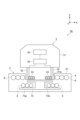
図1は、本開示の実施形態に係る給電システム及び給電装置の構成概要図である。給電システム1は、給電装置2及び飛行体3により構成されている。給電装置2は、飛行体3へワイヤレス給電を行う装置である。この給電システム1及び給電装置2において、給電方式としては、例えば電磁誘導式、磁界共振式などを用いることができる。飛行体3は、給電対象であり、遠隔操作などにより飛行する無人航空機(Unmanned Aerial Vehicle、以下、UAVという)である。例えば、飛行体3は、複数のロータを備えたマルチコプター、いわゆるドローンである。給電装置2は、給電部4、送電コイル5、第三コイル6、第一磁性体71及び第二磁性体72を備えている。
FIG. 1 is a schematic diagram of a power supply system and a power supply device according to an embodiment of the present disclosure. The
図1に示すように、給電部4は、飛行体3を給電位置に位置させて飛行体3へ給電を行うためのものであり、例えば、内部に送電コイル5などを収容可能な箱体を有している。給電部4は、飛行体3を着陸可能な大きさで形成され、その上面41に飛行体3を着陸可能に構成される。例えば、上面41には下方へ窪む凹部41aが形成されている。凹部41aは、飛行体3の脚部32を収容可能な大きさに形成されている。つまり、飛行体3の本体31から下方へ延びる複数の脚部32を全て収容できるように、凹部41aが形成されている。図1では、凹部41aの形成位置が飛行体3の給電位置となっている。
As shown in FIG. 1, the
給電部4内には、送電コイル5が設けられている。送電コイル5は、通電(電力供給)により磁界を発生させるコイルである。ここで、コイルとは、巻線を意味し、磁束を集中させるための磁性部材を含まない。送電コイル5は、給電部4の内部であって凹部41aの下方の位置に設置されている。送電コイル5は、例えば線材を環状に巻いて構成され、鉛直方向に延びる軸線Cを中心に配置されている。軸線Cは、飛行体3の給電位置の中央を通過する線である。送電コイル5は、通電により磁界を発生させる。すなわち、送電コイル5は、図示しない送電回路に接続され、送電回路から交流電力を供給されることにより、軸線Cに沿った向きに磁界を発生させる。
The
給電部4内には、第三コイル6が設けられている。第三コイル6は、軸線Cを中心とし送電コイル5と同軸状に配置され、送電コイル5から発生される磁界を受けて送電コイル5と磁気結合する。第三コイル6は、給電部4の内部であって凹部41aの周囲を覆うように設置されている。すなわち、第三コイル6は、例えば線材を環状に巻いて構成され、中央に凹部41aを貫通させるように設けられている。この第三コイル6は、送電コイル5と受電コイル33を磁気結合させるための中継コイルとして機能する。
A
給電部4内には、第一磁性体71が設けられている。第一磁性体71は、送電コイル5と第三コイル6の磁気結合に用いられる磁性体であって、送電コイル5の背面側に配置されている。すなわち、第一磁性体71は、送電コイル5の下方で上面41と平行に配置され、送電コイル5と磁気結合する第三コイル6に対し背面側に配置されている。この第一磁性体71により、送電コイル5により発生される磁界が第三コイル6側に向けて形成される。このため、送電コイル5と第三コイル6の磁気結合が高められる。第一磁性体71は、板状の磁性材であり、例えば円板状のフェライトにより構成される。
A first
給電部4内には、第二磁性体72が設けられている。第二磁性体72は、送電コイル5と受電コイル33の間に配置される磁性体であり、第三コイル6と受電コイル33の磁気結合に用いられる。この第二磁性体72は、板状の磁性材であり、例えば円板状のフェライトにより構成される。第二磁性体72は、上面41と平行に設けられ、飛行体3が給電位置に位置している場合の受電コイル33の下方の位置であって、送電コイル5の上方の位置に設けられている。受電コイル33の下方に第二磁性体72が設けられることにより、受電コイル33のインダクタンスを大きくし、受電コイル33のQ値を高くすることができる。
A second
飛行体3は、受電コイル33、充電回路34及びバッテリ35を備えている。受電コイル33は、給電時に第三コイル6と磁気結合するコイルであって、飛行体3の下部に設けられている。例えば、受電コイル33は、飛行体3の本体31から下方へ延びる脚部32に取り付けられている。受電コイル33は、例えば線材を環状に巻いて構成され、飛行体3の着陸時に鉛直方向を中心となるように設けられている。つまり、受電コイル33は、飛行体3が給電位置に位置している場合、凹部41a内へ配置され、第三コイル6の内側に配置される。このとき、受電コイル33は、軸線Cを中心として、第三コイル6及び送電コイル5と同軸状に配置される。また、受電コイル33と第三コイル6は、軸線Cに沿った位置が同一とされる。すなわち、受電コイル33と第三コイル6の高さ位置は同一とされ、受電コイル33と第三コイル6は同心状に配置される。これにより、第三コイル6と受電コイル33の磁気結合を高めることができる。ここで、同軸状とは、給電効率が所定以上に低下しない程度のほぼ同軸状も含む。また、同心状とは、給電効率が所定以上に低下しない程度のほぼ同心状も含む。受電コイル33は、第三コイル6と磁気結合し、誘導起電力を生ずる。受電コイル33は充電回路34と接続され、受電コイル33に生じた電力は充電回路34を介してバッテリ35に充電される。充電回路34及びバッテリ35は、例えば飛行体3の本体31に収容されている。また、飛行体3の本体31には、図示しない複数のロータが取り付けられている。このロータの回転により、飛行体3は飛行する。
The flying
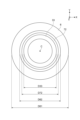
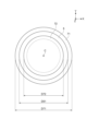
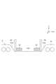
図2は図1のII-IIにおける給電装置2の水平断面の概要図であり、図3は図1のIII-IIIにおける給電装置2の水平断面の概要図である。この図2及び図3は、送電コイル5、第三コイル6、第一磁性体71及び第二磁性体72の大きさを説明するための図であり、説明の便宜上、給電部4のハウジング及び飛行体3の脚部32の断面の図示を省略している。
Figure 2 is a schematic diagram of a horizontal cross section of the
図2及び図3に示すように、送電コイル5、第三コイル6、第一磁性体71及び第二磁性体72は、軸線Cを中心として同軸状に配置されている。また、飛行体3が給電位置に位置している場合、送電コイル5、第三コイル6、第一磁性体71、第二磁性体72及び受電コイル33は、軸線Cを中心として同軸状に配置される。
2 and 3, the
図2において、第三コイル6の内周側に受電コイル33が位置しており、受電コイル33の下方に第二磁性体72が位置している。つまり、飛行体3が給電位置に位置している場合、受電コイル33は、第三コイル6の内周側に位置している。このため、第三コイル6の内径D62は、受電コイル33の外径D33以上の大きさとされる。飛行体3の位置が適正な給電位置からズレた場合でも、第三コイル6と受電コイル33がほぼ同軸状となるように、第三コイル6の内径D62と受電コイル33の外径D33が設定される。また、第三コイル6の外径D61は第二磁性体72の外径D72以上の大きさとされ、第二磁性体72の外径D72は受電コイル33の外径D33以上の大きさとされる。第三コイル6の外径D61を第二磁性体72の外径D72以上の大きさとすることにより、第三コイル6と送電コイル5の磁気結合が可能となる。
2, the
図3において、第二磁性体72の下方に送電コイル5が位置しており、送電コイル5の下方に第一磁性体71が位置している。図3における破線は、送電コイル5の内縁を示している。送電コイル5の外径D51は、第二磁性体72の外径D72より大きい。このため、送電コイル5と第三コイル6の磁気結合が可能となる。また、第一磁性体71の外径D71は、送電コイル5の外径D51より大きい。これにより、送電コイル5と第三コイル6の磁気結合を高めることができる。
In FIG. 3, the
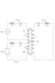
図4は、送電コイル5、第三コイル6及び受電コイル33の結合状態を示す等価回路である。送電コイル5は、送電回路81に接続され、交流電力を入力される。また、送電コイル5は、コンデンサが直列に接続されている。コンデンサのキャパシタンスC1と送電コイル5のインダクタL1により共振周波数が決定される。r1は、送電コイル5の巻線抵抗である。第三コイル6は、送電コイル5と磁気結合し、誘導起電力を生じさせる。第三コイル6は、コンデンサが直列に接続されている。コンデンサのキャパシタンスC2と第三コイル6のインダクタンスL2により共振周波数が決定される。r2は、第三コイル6の巻線抵抗である。送電コイル5と第三コイル6の結合係数K12は、主に送電コイル5、第三コイル6、第一磁性体71及び第二磁性体72の位置や大きさなどにより決定される。
FIG. 4 is an equivalent circuit showing a coupling state of the
受電コイル33は、第三コイル6と磁気結合し、誘導起電力を生じさせる。受電コイル33は充電回路34に接続され、充電回路34を通じて誘導起電力がバッテリ35に充電される。受電コイル33には、コンデンサが直列に接続されている。コンデンサのキャパシタンスC3と受電コイル33のインダクタンスL3により共振周波数が決定される。r3は、受電コイル33の巻線抵抗である。送電コイル5、第三コイル6及び受電コイル33の共振周波数は、同一又はほぼ同一となるように設定される。受電コイル33と第三コイル6の結合係数K23は、主に受電コイル33、第三コイル6及び第二磁性体72の位置関係や大きさなどにより決定される。また、受電コイル33と送電コイル5の結合係数K12は、主に受電コイル33、送電コイル5、第一磁性体71及び第二磁性体72の位置関係や大きさなどにより決定される。
The receiving
結合係数K12、結合係数K23及び結合係数K13の関係としては、結合係数K23が結合係数K13より大きく、結合係数K23が結合係数K12より大きく設定される。このような関係とすることにより、受電コイル33を小型化しても給電効率を高くすることができる。図1に示すように、第三コイル6の内側に受電コイル33を配置することにより、結合係数K23を大きくすることができる。また、飛行体3の着陸位置が適正な給電位置からズレた場合でも、結合係数K23の低下を抑制することができ、給電効率の低下を抑制することができる。
The relationship between the coupling coefficient K12 , the coupling coefficient K23 , and the coupling coefficient K13 is set such that the coupling coefficient K23 is greater than the coupling coefficient K13 , and the coupling coefficient K23 is greater than the coupling coefficient K12 . This relationship makes it possible to increase the power supply efficiency even if the
なお、図4では、送電コイル5、第三コイル6及び受電コイル33に対し直列にコンデンサを接続してマッチング回路(共振回路)を構成しているが、送電コイル5、第三コイル6及び受電コイル33の一部又は全部に対し並列にコンデンサを接続してマッチング回路を構成してもよい。
In FIG. 4, a matching circuit (resonant circuit) is formed by connecting capacitors in series to the
次に、本実施形態に係る給電装置2及び給電システム1の動作について説明する。
Next, the operation of the
図1に示すように、飛行体3に対し給電を行うべく、飛行する飛行体3を給電部4上へ着陸させる。飛行体3は、例えば遠隔操作により飛行制御され、給電部4の給電位置へ着陸する。すなわち、飛行体3は、給電位置である凹部41aに着陸する。このとき、飛行体3の脚部32に取り付けられる受電コイル33が凹部41a内に配置される。このため、給電部4内に設けられる第三コイル6の内側に受電コイル33が配置されることとなる。つまり、第三コイル6と受電コイル33は、軸線Cを中心として同軸状に配置され、同じ高さで同心状に配置される。このため、第三コイル6と受電コイル33の磁気結合は高いものとなる。
As shown in FIG. 1, in order to supply power to the flying
そして、給電装置2を作動させて飛行体3に対する給電が行われる。送電コイル5に対し送電回路81から交流電圧が印加され、送電コイル5が通電される。これにより、送電コイル5は、軸線Cに沿って磁界を発生させる。このとき、送電コイル5の下方には第一磁性体71が配置されているため、送電コイル5により発生した磁界は、送電コイル5の上方へ形成される。送電コイル5と受電コイル33の間には第二磁性体72が配置されているが、送電コイル5は第二磁性体72より大きく形成されているため、送電コイル5から発生される磁界は、第三コイル6に向けて形成される。
Then, the
第三コイル6は、送電コイル5から発生される磁界を受けて、送電コイル5と磁気結合し、誘導起電力を生ずる。このとき、第三コイル6を貫く方向に磁界が形成され、この磁界を受けて、受電コイル33は第三コイル6と磁気結合する。ここで、受電コイル33の下方に第二磁性体72が配置されているため、受電コイル33と第三コイル6の磁気結合が高められる。これにより、受電コイル33の背面側(飛行体3側)に磁性体を配置しなくても、第三コイル6と受電コイル33を強く磁気結合させることができる。つまり、飛行体3に磁性体を設けることなく、受電コイル33と第三コイル6を強く磁気結合することができる。そして、受電コイル33に誘導起電力が生じ、充電回路34を介してバッテリ35が充電される。
The
このように、第三コイル6を設けることにより、受電コイル33の背面側に磁性体を設けることなく、送電コイル5から発生された磁界によって受電コイル33に誘導起電力を生じさせて、飛行体3の給電を行うことができる。このため、飛行体3に磁気結合のための磁性体の設置が不要となり、飛行体3の軽量化を図ることができる。
In this way, by providing the
以上説明したように、本実施形態に係る給電装置2及び給電システム1によれば、給電部4に第三コイル6を設けることにより、この第三コイル6を介して送電コイル5と受電コイル33を磁気結合させることができる。また、第三コイル6と受電コイル33の磁気結合させる第二磁性体72を備えることにより、第三コイル6と受電コイル33の磁気結合を高めて給電効率の低下を抑制することができる。このため、給電効率の低下を抑制しつつ、受電コイル33の背面側の磁性体の設置を省略することができる。従って、飛行体3に磁気結合のための磁性体の設置が不要となり、飛行体3の軽量化を図ることができる。
As described above, according to the
また、本実施形態に係る給電装置2及び給電システム1によれば、第三コイル6は給電部4に設けられるため、第三コイル6の設置により飛行体3の重量が増加することを避けることができる。さらに、給電部4の給電位置に上方への凸部を形成する必要がないため、飛行体3の下部の空間を有効利用することができ、給電位置への飛行体3の移動操作が容易となる。つまり、飛行体3の脚部32と脚部32の間の空間を有効利用することができる。
In addition, according to the
また、本実施形態に係る給電装置2及び給電システム1において、飛行体3が給電位置に位置した場合に受電コイル33が第三コイル6の内周側に配置される。このため、第三コイル6と受電コイル33の磁気結合を強めることができ、給電効率を高めることができる。また、受電コイル33を小さく構成することができ、受電コイル33を搭載する飛行体3の軽量化を図ることができる。
In addition, in the
また、本実施形態に係る給電装置2及び給電システム1において、飛行体3が給電位置に位置した場合に受電コイル33、送電コイル5及び第三コイル6が同軸状に配置される。このため、第三コイル6を介して受電コイル33と送電コイル5を強く磁気結合させることができ、給電効率を高めることができる。
In addition, in the
また、本実施形態に係る給電装置2及び給電システム1において、給電対象が飛行体3であるため、飛行する飛行体3の軽量化が図れ、飛行体3の運動性能を高めることができる。また、飛行体3を軽量化することで、飛行体3の飛行時間を長くすることが可能となる。
In addition, in the
以上のように本開示の実施形態に係る給電装置2及び給電システム1について説明したが、本開示の給電装置及び給電システムは、上述した実施形態に限定されるものではない。本開示の発明は、特許請求の範囲の記載の要旨を逸脱しない範囲で様々な変形態様をとることができる。
Although the
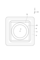
例えば、上述した実施形態においては、図2及び図3に示すように、送電コイル5、第三コイル6、受電コイル33、第一磁性体71及び第二磁性体72の外縁の形状が円形であったが、それらの形状は円形以外であってもよい。例えば、送電コイル5、第三コイル6、受電コイル33、第一磁性体71及び第二磁性体72の一部又は全部における外縁の形状が円形以外の形状であってもよい。具体的には、図5に示すように、受電コイル33の外縁の形状が円形であり、送電コイル5、第三コイル6、第一磁性体71及び第二磁性体72の外縁の形状が矩形ないしほぼ矩形であってもよい。このような給電装置2及び給電システム1であっても、上述した実施形態と同様な作用効果を得ることができる。
For example, in the above-described embodiment, as shown in FIG. 2 and FIG. 3, the outer edges of the
また、上述した実施形態においては、送電コイル5、第三コイル6及び受電コイル33の磁気結合のための磁性体として第一磁性体71及び第二磁性体72を備えていたが、この第一磁性体71及び第二磁性体72を一体にした磁性体を用いてもよい。例えば、図6に示すように、第一磁性部73aと第二磁性部73bを連結した磁性体73を用いてもよい。つまり、第一磁性部73aを送電コイル5の背面側に設け、第二磁性部73bを送電コイル5と受電コイル33の間に設け、この第一磁性部73aと第二磁性部73bを中央で連結した磁性体73を用いてもよい。この場合であっても、上述した実施形態と同様な作用効果を得ることができる。
In the above-described embodiment, the first
また、上述した実施形態においては、給電部4の凹部41aが垂直に窪んだ形状であったが、凹部41aの側壁を傾斜面41bとしてもよい。例えば、図7に示すように、底部にいくほど凹部41aの水平断面が小さくなるように側壁を傾斜させて傾斜面41bとしてもよい。この場合、凹部41aの開口が底面より大きくなるため、飛行する飛行体3が着陸する時に給電位置から外れていても、傾斜面41bにより飛行体3を給電位置へ案内することができ、飛行体3の操作が容易となる。
In the above-described embodiment, the
また、上述した実施形態において、給電部4を屋外に設置する場合、凹部41aに水抜き用の配管を設けてもよい。例えば、凹部41aの底から給電部4の外部へ通ずる配管を設けてもよい。この配管を通じて凹部41aの底に溜まる雨水を排出することができる。
In addition, in the above-described embodiment, when the
また、上述した実施形態においては、給電部4の上面41に凹部41aを形成していたが、上面41に凹部41aを形成せず上面41をフラットな形状としてもよい。この場合、上面41に凹凸がないため、上面41に雨水が溜まることを抑制することができる。また、上面41に塵や埃などが溜まることを抑制することができる。このため、給電部4のメンテナンスが容易となる。上面41をフラットにすることで、飛行体3が適正な給電位置から横方向に外れて位置し給電効率が下がる可能性があるが、飛行体3を上面41に着陸させた後、前後左右の位置を微調整して飛行体3を適切に給電位置に位置させることにより、効率良い給電を行うことができる。
In the above embodiment, the
また、上述した実施形態においては、給電対象が飛行体3である場合について説明したが、給電対象は飛行体3以外の移動体であってもよい。例えば、陸上を移動する車両や水中を移動する水中ロボットなどであってもよい。また、給電対象は、スマートフォンなどのように人が携帯する物であってもよい。この場合、携帯する給電対象を軽量化できるため、給電対象が取り扱いしやすい物となる。
In the above embodiment, the power supply target is an
1 給電システム
2 給電装置
3 飛行体
4 給電部
5 送電コイル
6 第三コイル
31 本体
32 脚部
33 受電コイル
34 充電回路
35 バッテリ
41 上面
41a 凹部
41b 傾斜面
71 第一磁性体
72 第二磁性体
81 送電回路
C 軸線
Claims (5)
前記給電対象を給電位置に位置させて前記給電対象への給電を行うための給電部と、
前記給電部に設けられ、通電により磁界を発生させる送電コイルと、
前記給電部に設けられ、前記送電コイルから発生される磁界を受けて前記送電コイルと磁気結合し、前記給電対象が前記給電位置に位置している場合に前記給電対象に設けられる受電コイルと磁気結合する第三コイルと、
前記給電部に設けられ、前記第三コイルと前記受電コイルの磁気結合に用いられる磁性体と、を備え、
前記給電部は、前記第三コイルに周囲を覆われるように設置された凹部を含み、前記送電コイル、前記第三コイル及び前記磁性体を収容可能である箱体を有し、
前記磁性体は、前記凹部の底面と前記送電コイルとの間に配置される、
給電装置。 In a power supply device that wirelessly supplies power to a power supply target,
a power supply unit for positioning the power supply target at a power supply position and supplying power to the power supply target;
a power transmission coil provided in the power supply unit and configured to generate a magnetic field when energized;
a third coil provided in the power supply unit, magnetically coupled to the power transmission coil upon receiving a magnetic field generated by the power transmission coil, and magnetically coupled to a power receiving coil provided in the power supply target when the power supply target is located at the power supply position;
a magnetic body provided in the power supply unit and used for magnetic coupling between the third coil and the power receiving coil ,
the power supply unit has a box body including a recessed portion disposed so as to be surrounded by the third coil and capable of accommodating the power transmission coil, the third coil, and the magnetic body;
The magnetic body is disposed between a bottom surface of the recess and the power transmitting coil.
Power supply device.
請求項1に記載の給電装置。 the power receiving coil is formed smaller than the third coil and is disposed on the inner circumferential side of the third coil when the power supply target is located at the power supply position;
The power supply device according to claim 1 .
請求項1又は2に記載の給電装置。 the power transmitting coil and the third coil are provided coaxially, and when the power supply target is located at the power supply position, the power receiving coil, the power transmitting coil, and the third coil are arranged coaxially.
The power supply device according to claim 1 or 2.
前記給電対象に設けられる受電コイルと、
前記給電対象を給電位置に位置させて前記給電対象への給電を行うための給電部と、
前記給電部に設けられ、通電により磁界を発生させる送電コイルと、
前記給電部に設けられ、前記送電コイルから発生される磁界を受けて前記送電コイルと磁気結合し、前記給電対象が前記給電位置に位置している場合に前記受電コイルと磁気結合する第三コイルと、
前記給電部に設けられ、前記第三コイルと前記受電コイルの磁気結合に用いられる磁性体と、備え、
前記給電部は、前記第三コイルに周囲を覆われるように設置された凹部を含み、前記送電コイル、前記第三コイル及び前記磁性体を収容可能である箱体を有し、
前記磁性体は、前記凹部の底面と前記送電コイルとの間に配置される、給電システム。 In a power supply system that wirelessly supplies power to a power supply target,
A power receiving coil provided in the power supply target;
a power supply unit for positioning the power supply target at a power supply position and supplying power to the power supply target;
a power transmission coil provided in the power supply unit and configured to generate a magnetic field when energized;
a third coil provided in the power supply unit, magnetically coupled to the power transmission coil when receiving a magnetic field generated by the power transmission coil, and magnetically coupled to the power receiving coil when the power supply target is located at the power supply position;
a magnetic body provided in the power supply unit and used for magnetic coupling between the third coil and the power receiving coil ;
the power supply unit has a box body including a recessed portion disposed so as to be surrounded by the third coil and capable of accommodating the power transmission coil, the third coil, and the magnetic body;
The magnetic body is disposed between a bottom surface of the recess and the power transmitting coil .
Priority Applications (2)
| Application Number | Priority Date | Filing Date | Title |
|---|---|---|---|
| JP2021033368A JP7621613B2 (en) | 2021-03-03 | 2021-03-03 | Power supply device and power supply system |
| US17/683,536 US11742699B2 (en) | 2021-03-03 | 2022-03-01 | Power feeding device and power feeding system |
Applications Claiming Priority (1)
| Application Number | Priority Date | Filing Date | Title |
|---|---|---|---|
| JP2021033368A JP7621613B2 (en) | 2021-03-03 | 2021-03-03 | Power supply device and power supply system |
Publications (2)
| Publication Number | Publication Date |
|---|---|
| JP2022134313A JP2022134313A (en) | 2022-09-15 |
| JP7621613B2 true JP7621613B2 (en) | 2025-01-27 |
Family
ID=83117557
Family Applications (1)
| Application Number | Title | Priority Date | Filing Date |
|---|---|---|---|
| JP2021033368A Active JP7621613B2 (en) | 2021-03-03 | 2021-03-03 | Power supply device and power supply system |
Country Status (2)
| Country | Link |
|---|---|
| US (1) | US11742699B2 (en) |
| JP (1) | JP7621613B2 (en) |
Families Citing this family (2)
| Publication number | Priority date | Publication date | Assignee | Title |
|---|---|---|---|---|
| US11973542B2 (en) * | 2019-04-17 | 2024-04-30 | Lg Electronics Inc. | Method for controlling communication connection in wireless power transmission system, and apparatus therefor |
| US11881719B2 (en) | 2019-09-12 | 2024-01-23 | Spark Connected LLC | Wireless power transfer object detection circuit and method |
Citations (6)
| Publication number | Priority date | Publication date | Assignee | Title |
|---|---|---|---|---|
| JP2017135880A (en) | 2016-01-28 | 2017-08-03 | 日立マクセル株式会社 | Wireless power supply system |
| JP2017147784A (en) | 2016-02-15 | 2017-08-24 | 株式会社ダイヘン | Contactless charging system |
| US20180138745A1 (en) | 2015-04-17 | 2018-05-17 | 3I Innovation Limited | Inductive power transfer apparatus with improved coupling |
| JP2020511918A (en) | 2017-03-07 | 2020-04-16 | パワーマット テクノロジーズ リミテッド | System for wireless power charging |
| US20200227950A1 (en) | 2019-01-15 | 2020-07-16 | Samsung Electronics Co., Ltd. | Wireless power relaying device and display system that distributes power wirelessly |
| JP2020202734A (en) | 2019-06-13 | 2020-12-17 | 株式会社東芝 | Wireless power transmission device and wireless power transmission method |
Family Cites Families (28)
| Publication number | Priority date | Publication date | Assignee | Title |
|---|---|---|---|---|
| EP2543535A4 (en) * | 2010-03-04 | 2014-05-14 | Honda Motor Co Ltd | ELECTRIC VEHICLE |
| JP2011234605A (en) * | 2010-04-05 | 2011-11-17 | Tdk Corp | Wireless power reception device and wireless power transmission system |
| JP5843309B2 (en) | 2011-02-24 | 2016-01-13 | 国立大学法人東北大学 | Non-contact power transmission system |
| US9035500B2 (en) * | 2011-03-01 | 2015-05-19 | Tdk Corporation | Wireless power feeder, wireless power receiver, and wireless power transmission system, and coil |
| US8922064B2 (en) * | 2011-03-01 | 2014-12-30 | Tdk Corporation | Wireless power feeder, wireless power receiver, and wireless power transmission system, and coil |
| JP6300107B2 (en) * | 2013-01-30 | 2018-03-28 | パナソニックIpマネジメント株式会社 | Non-contact power transmission device |
| EP2996221B1 (en) | 2013-05-10 | 2017-10-04 | IHI Corporation | Contactless power supply system |
| JP6146119B2 (en) | 2013-05-13 | 2017-06-14 | 株式会社Ihi | Non-contact power supply system and bag system |
| US9281720B2 (en) * | 2013-05-31 | 2016-03-08 | ConvenientPower HK Ltd. | Inductive power transfer using a relay coil |
| JP6297863B2 (en) | 2014-03-03 | 2018-03-20 | Ihi運搬機械株式会社 | Non-contact power feeding system and vehicle power feeding device |
| JP6228720B2 (en) | 2014-03-21 | 2017-11-08 | Ihi運搬機械株式会社 | Non-contact power feeding system and vehicle power feeding device |
| JP6280404B2 (en) | 2014-03-18 | 2018-02-14 | Ihi運搬機械株式会社 | Non-contact power feeding system and vehicle power feeding device |
| CN106103867B (en) | 2014-03-18 | 2018-11-09 | 株式会社Ihi | Contactless power supply system is with vehicle for electric installation |
| JP6354437B2 (en) | 2014-08-08 | 2018-07-11 | 日産自動車株式会社 | Non-contact power feeding device |
| JP6555517B2 (en) | 2015-07-16 | 2019-08-07 | 清水建設株式会社 | Wireless power supply system |
| JP6416058B2 (en) | 2015-09-01 | 2018-10-31 | 株式会社Lixil | Outdoor power feeder |
| JP6120116B2 (en) | 2015-10-02 | 2017-04-26 | パナソニックIpマネジメント株式会社 | Wireless power transmission system |
| WO2017159330A1 (en) * | 2016-03-18 | 2017-09-21 | 株式会社村田製作所 | Power transmission device, power reception device, and wireless power feeding system |
| JP2017212830A (en) | 2016-05-26 | 2017-11-30 | 菊地 秀雄 | Wireless power transmission system |
| JP6839803B2 (en) | 2017-01-26 | 2021-03-10 | パナソニックIpマネジメント株式会社 | lighting equipment |
| JP6610583B2 (en) * | 2017-03-09 | 2019-11-27 | Tdk株式会社 | Wireless power transmission system |
| JP6594373B2 (en) | 2017-05-10 | 2019-10-23 | パナソニック株式会社 | Power transmission equipment |
| JP6774391B2 (en) | 2017-08-08 | 2020-10-21 | 大井電気株式会社 | Non-contact power supply device |
| US11394247B1 (en) * | 2017-08-30 | 2022-07-19 | Roman Tsibulevskiy | Charging technologies |
| CN112868162A (en) * | 2018-05-31 | 2021-05-28 | 鲍尔马特技术有限公司 | System and method for determining Q factor |
| US11653627B2 (en) * | 2018-09-19 | 2023-05-23 | Lg Electronics Inc. | Liquid dispenser for animals |
| US11973542B2 (en) * | 2019-04-17 | 2024-04-30 | Lg Electronics Inc. | Method for controlling communication connection in wireless power transmission system, and apparatus therefor |
| KR20210109916A (en) | 2020-02-28 | 2021-09-07 | 삼성전자주식회사 | Wireless charging device and method for charging electronic device using the same |
-
2021
- 2021-03-03 JP JP2021033368A patent/JP7621613B2/en active Active
-
2022
- 2022-03-01 US US17/683,536 patent/US11742699B2/en active Active
Patent Citations (6)
| Publication number | Priority date | Publication date | Assignee | Title |
|---|---|---|---|---|
| US20180138745A1 (en) | 2015-04-17 | 2018-05-17 | 3I Innovation Limited | Inductive power transfer apparatus with improved coupling |
| JP2017135880A (en) | 2016-01-28 | 2017-08-03 | 日立マクセル株式会社 | Wireless power supply system |
| JP2017147784A (en) | 2016-02-15 | 2017-08-24 | 株式会社ダイヘン | Contactless charging system |
| JP2020511918A (en) | 2017-03-07 | 2020-04-16 | パワーマット テクノロジーズ リミテッド | System for wireless power charging |
| US20200227950A1 (en) | 2019-01-15 | 2020-07-16 | Samsung Electronics Co., Ltd. | Wireless power relaying device and display system that distributes power wirelessly |
| JP2020202734A (en) | 2019-06-13 | 2020-12-17 | 株式会社東芝 | Wireless power transmission device and wireless power transmission method |
Also Published As
| Publication number | Publication date |
|---|---|
| US20220285992A1 (en) | 2022-09-08 |
| JP2022134313A (en) | 2022-09-15 |
| US11742699B2 (en) | 2023-08-29 |
Similar Documents
| Publication | Publication Date | Title |
|---|---|---|
| US10811905B2 (en) | Power transmission device, vehicle, and wireless power transmission device | |
| CN108688496B (en) | UAV wireless charging system and UAV | |
| US11332025B2 (en) | Multi-directional wireless charging of vehicles and robots | |
| JP6584971B2 (en) | Wireless power supply system | |
| JP6233780B2 (en) | Wireless power transmission system | |
| JP5673810B2 (en) | Power receiving device, power transmitting device, and power transmission system | |
| JP5547359B1 (en) | Non-contact power supply system and non-contact power supply method | |
| US11581758B2 (en) | Power transfer coil | |
| JP7621613B2 (en) | Power supply device and power supply system | |
| US10243411B2 (en) | Wireless charger with uniform H-field generator and EMI reduction | |
| US20140111021A1 (en) | Power transmission device, power reception device and power transfer system | |
| US9917478B2 (en) | Power transmission device, power reception device and power transfer system | |
| US9531217B2 (en) | Power reception device, power transmission device and power transfer system | |
| Assaf et al. | Autonomous underwater biorobots: A wireless system for power transfer | |
| JP2013126327A (en) | Power receiving apparatus, vehicle including the same, power transmission apparatus, and power transmission system | |
| JP2012248747A (en) | Shield device of resonance type non-contact power supply system | |
| WO2013150365A2 (en) | Vehicle | |
| CN103827997A (en) | Power receiving device, power transmitting device, and power transmission system | |
| US10177603B2 (en) | Coil unit and power supply system including the same | |
| JP2012049434A (en) | Electronic component, feeder device, power receiver, and wireless feeder system | |
| US20140246901A1 (en) | Power reception device, vehicle including power reception device, and power transfer system | |
| CN111559260A (en) | Unmanned aerial vehicle wireless charging system | |
| JP2020202734A (en) | Wireless power transmission device and wireless power transmission method | |
| CN110729820B (en) | UAV, its onboard wireless receiving unit, and its anti-offset coupling coil for wireless charging | |
| RU165925U1 (en) | DEVICE FOR CONTACTLESS POWER TAKE-OFF FROM HIGH VOLTAGE ELECTRIC TRANSMISSION LINES ON AIRCRAFT |
Legal Events
| Date | Code | Title | Description |
|---|---|---|---|
| A621 | Written request for application examination |
Free format text: JAPANESE INTERMEDIATE CODE: A621 Effective date: 20231109 |
|
| A977 | Report on retrieval |
Free format text: JAPANESE INTERMEDIATE CODE: A971007 Effective date: 20241001 |
|
| A131 | Notification of reasons for refusal |
Free format text: JAPANESE INTERMEDIATE CODE: A131 Effective date: 20241008 |
|
| A521 | Request for written amendment filed |
Free format text: JAPANESE INTERMEDIATE CODE: A523 Effective date: 20241205 |
|
| TRDD | Decision of grant or rejection written | ||
| A01 | Written decision to grant a patent or to grant a registration (utility model) |
Free format text: JAPANESE INTERMEDIATE CODE: A01 Effective date: 20241217 |
|
| A61 | First payment of annual fees (during grant procedure) |
Free format text: JAPANESE INTERMEDIATE CODE: A61 Effective date: 20250106 |
|
| R150 | Certificate of patent or registration of utility model |
Ref document number: 7621613 Country of ref document: JP Free format text: JAPANESE INTERMEDIATE CODE: R150 |