JP7617552B2 - Blower and Blower System - Google Patents

Blower and Blower System Download PDF

Info

Publication number
JP7617552B2
JP7617552B2 JP2020182625A JP2020182625A JP7617552B2 JP 7617552 B2 JP7617552 B2 JP 7617552B2 JP 2020182625 A JP2020182625 A JP 2020182625A JP 2020182625 A JP2020182625 A JP 2020182625A JP 7617552 B2 JP7617552 B2 JP 7617552B2
Authority
JP
Japan
Prior art keywords
air
frame
blower
plate
holes
Prior art date
Legal status (The legal status is an assumption and is not a legal conclusion. Google has not performed a legal analysis and makes no representation as to the accuracy of the status listed.)
Active
Application number
JP2020182625A
Other languages
Japanese (ja)
Other versions
JP2022072922A (en
Inventor
祐司 尾崎
義宣 桃井
博睦 小山
Current Assignee (The listed assignees may be inaccurate. Google has not performed a legal analysis and makes no representation or warranty as to the accuracy of the list.)
Panasonic Intellectual Property Management Co Ltd
Original Assignee
Panasonic Intellectual Property Management Co Ltd
Priority date (The priority date is an assumption and is not a legal conclusion. Google has not performed a legal analysis and makes no representation as to the accuracy of the date listed.)
Filing date
Publication date
Application filed by Panasonic Intellectual Property Management Co Ltd filed Critical Panasonic Intellectual Property Management Co Ltd
Priority to JP2020182625A priority Critical patent/JP7617552B2/en
Publication of JP2022072922A publication Critical patent/JP2022072922A/en
Application granted granted Critical
Publication of JP7617552B2 publication Critical patent/JP7617552B2/en
Active legal-status Critical Current
Anticipated expiration legal-status Critical

Links

Images

Landscapes

  • Duct Arrangements (AREA)

Description

本開示は、送風装置、及び送風システムに関する。 This disclosure relates to a blower device and a blower system.

特許文献1の空気清浄装置は、空気吸込口及び空気吹出口を有するケーシングを備え、ケーシングの内部において、案内板を設けている。案内板は、ケーシングのほぼ中央に配置されており、案内板とケーシングの周板との間には、空気を通す間隙が設けられている。さらに、案内板の下側には、空気吹出口の内側周縁を覆うバッフル板が設けられている。案内板は、ファンによってケーシングの内部に送り込まれた空気を周板に向けて案内しつつ、間隙を介して空気吹出口に向けて送る。空気吹出口の口形の中央に対応する位置には開口が形成されており、バッフル板は、空気の流れを開口に向けて整流する。 The air purifier of Patent Document 1 has a casing with an air inlet and an air outlet, and a guide plate is provided inside the casing. The guide plate is located approximately in the center of the casing, and a gap is provided between the guide plate and the peripheral plate of the casing to allow air to pass through. In addition, a baffle plate that covers the inner periphery of the air outlet is provided below the guide plate. The guide plate guides air sent into the casing by the fan toward the peripheral plate, while sending it toward the air outlet through the gap. An opening is formed in a position corresponding to the center of the mouth shape of the air outlet, and the baffle plate straightens the air flow toward the opening.

特開2006-112755号公報JP 2006-112755 A

特許文献1の空気清浄装置のような空調装置は、例えば天井などの構造体に設置される。このような空調装置には、施工のしやすさ、及び空調装置としての機能の安定を図るために、軽量化と強度の確保との両立が求められている。 Air conditioners such as the air purifier of Patent Document 1 are installed on structures such as ceilings. Such air conditioners are required to be both lightweight and strong in order to ensure ease of installation and stable function as an air conditioner.

本開示の目的は、軽量化と強度の確保との両立を実現することができる送風装置、及び送風システムを提供することである。 The objective of this disclosure is to provide a blower device and a blower system that can achieve both lightweight design and strength.

本開示の一態様に係る送風装置は、筐体と、整流板と、駆動機構と、を備える。前記筐体は、内部空間を有する箱状に形成されており、前記内部空間に空気を送り込むための給気口、及び前記内部空間の外部である空調空間に前記空気を吐き出すための送風口を有する。前記整流板は、前記給気口と前記送風口との間に配置されている。前記駆動機構は、前記整流板を、前記送風口の軸方向と交差する方向に移動させる。前記筐体は、金属で形成され、少なくとも1つの貫通孔を有しているフレームと、樹脂で形成され、前記フレームの前記少なくとも1つの貫通孔を塞ぐ閉塞体と、を有する。前記駆動機構は、前記整流板を前記交差する方向に移動させる電動アクチュエータを有する。 A blower according to an aspect of the present disclosure includes a housing, a straightening vane, and a drive mechanism. The housing is formed in a box shape having an internal space, and has an air inlet for feeding air into the internal space, and an air outlet for discharging the air into an air-conditioned space outside the internal space. The straightening vane is disposed between the air inlet and the air outlet. The drive mechanism moves the straightening vane in a direction intersecting an axial direction of the air outlet . The housing includes a frame formed of metal and having at least one through hole, and a blocking body formed of resin and blocking the at least one through hole of the frame. The drive mechanism includes an electric actuator that moves the straightening vane in the intersecting direction .

本開示の一態様に係る送風システムは、送風口から空調空間へ前記空気として第1空気を吐き出す上述の送風装置と、前記空調空間の空気を第2空気として吸い込み、外部からの空気を第3空気として吸い込み、前記第2空気と前記第3空気とを混合した空気を前記第1空気として生成するチャンバ装置と、を備える。 The air blowing system according to one aspect of the present disclosure includes the above-mentioned air blowing device that blows out the first air as the air from an air outlet into an air-conditioned space, and a chamber device that draws in air from the air-conditioned space as second air, draws in air from the outside as third air, and generates a mixture of the second air and the third air as the first air.

以上説明したように、本開示は、軽量化と強度の確保との両立を実現することができるという効果がある。 As explained above, the present disclosure has the effect of achieving both weight reduction and strength.

図1は、実施形態の送風装置を備える送風システムの構成を示す側面図である。FIG. 1 is a side view showing a configuration of an air blowing system including an air blowing device according to an embodiment. 図2は、同上の送風システムが備える送風装置を示す斜視図である。FIG. 2 is a perspective view showing a blower device provided in the above blower system. 図3は、同上の送風装置を示す断面図である。FIG. 3 is a cross-sectional view showing the blower device of the same. 図4は、同上の送風装置を示す分解斜視図である。FIG. 4 is an exploded perspective view showing the blower device. 図5Aは、同上の送風装置が備える天板フレームを示す平面図である。図5Bは、同上の送風装置が備える枠体フレームを示す平面図である。5A and 5B are plan views showing a top plate frame and a frame body frame of the blower device, respectively. 図6は、同上の第1変形例の送風装置を示す斜視図である。FIG. 6 is a perspective view showing a blower device according to a first modified example of the above embodiment. 図7は、同上の第2変形例の送風装置が備える天板フレームを示す平面図である。FIG. 7 is a plan view showing a top plate frame provided in the blower device of the second modified example. 図8は、同上の第3変形例の送風装置が備える天板フレームを示す平面図である。FIG. 8 is a plan view showing a top plate frame provided in the blower device of the third modified example. 図9は、同上の送風システムを用いた気流制御システムの構成を示す図である。FIG. 9 is a diagram showing the configuration of an airflow control system using the above-mentioned blowing system.

本実施形態は、一般に、送風装置、及び送風システムに関する。より詳細には、本開示は、整流板を備える送風装置、及び送風システムに関する。 The present embodiment generally relates to a blower device and a blower system. More specifically, the present disclosure relates to a blower device and a blower system that include a straightening vane.

なお、以下に説明する実施形態は、本開示の実施形態の一例にすぎない。本開示は、以下の実施形態に限定されず、本開示の効果を奏することができれば、設計等に応じて種々の変更が可能である。 Note that the embodiment described below is merely an example of an embodiment of the present disclosure. The present disclosure is not limited to the following embodiment, and various modifications are possible depending on the design, etc., as long as the effects of the present disclosure can be achieved.

また、以下の説明では、特に断りのない限り、図2において、互いに直交するX軸、Y軸、及びZ軸を規定する。便宜的に、X軸に沿う両方向のうち一方向を右方向とし、他方向を左方向とする。また、Y軸に沿う両方向のうち一方向を前方向とし、他方向を後方向とする。また、Z軸に沿う両方向のうち一方向を上方向とし、他方向を下方向とする。 In the following description, unless otherwise specified, an X-axis, a Y-axis, and a Z-axis that are mutually perpendicular are defined in FIG. 2. For convenience, one of the two directions along the X-axis is defined as the rightward direction, and the other as the leftward direction. Furthermore, one of the two directions along the Y-axis is defined as the forward direction, and the other as the backward direction. Furthermore, one of the two directions along the Z-axis is defined as the upward direction, and the other as the downward direction.

(実施形態)
(1)送風システムの概略
図1は、本実施形態の送風システム1の構成を示す。送風システム1は、例えばオフィスビル、事務所、店舗、工場、又は商業施設などの施設に用いられる。また、送風システム1は、集合住宅の住戸、戸建て住宅などで用いられてもよい。
(Embodiment)
(1) Overview of the Air Blowing System Fig. 1 shows the configuration of an air blowing system 1 according to the present embodiment. The air blowing system 1 is used in facilities such as office buildings, offices, stores, factories, and commercial facilities. The air blowing system 1 may also be used in apartment buildings, detached houses, and the like.

送風システム1は、空調空間9の天井91に取り付けられている。この場合、天井91が、送風システム1を取り付ける構造体に相当する。 The air blowing system 1 is attached to the ceiling 91 of the air-conditioned space 9. In this case, the ceiling 91 corresponds to the structure on which the air blowing system 1 is attached.

送風システム1は、送風装置3、チャンバ装置4、ダクト5、及びコントローラK1を備える。コントローラK1は、チャンバ装置4を駆動して、チャンバ装置4の動作を制御する。チャンバ装置4は、空調空間9内の空気を第2空気A2として吸い込む。さらに、チャンバ装置4は、天井91の上方の天井裏空間92に配設されているダクトなどの外部通気路2に接続しており、図示しない空調設備から外部通気路2を介して送り出された第3空気A3を受け取る。そして、チャンバ装置4は、第2空気A2と第3空気A3とを混合した空気を第1空気A1として生成する。送風装置3とチャンバ装置4とはダクト5を介して互いに接続しており、チャンバ装置4は、ダクト5に第1空気A1を流し込むことで、送風装置3に第1空気A1を供給する。送風装置3は、ダクト5から供給された第1空気A1を空調空間9に吹き出す。 The air blowing system 1 includes an air blowing device 3, a chamber device 4, a duct 5, and a controller K1. The controller K1 drives the chamber device 4 to control the operation of the chamber device 4. The chamber device 4 draws in the air in the air-conditioned space 9 as the second air A2. Furthermore, the chamber device 4 is connected to an external air passage 2 such as a duct arranged in the ceiling space 92 above the ceiling 91, and receives the third air A3 sent from an air conditioning facility (not shown) through the external air passage 2. The chamber device 4 then generates the first air A1 by mixing the second air A2 and the third air A3. The air blowing device 3 and the chamber device 4 are connected to each other through the duct 5, and the chamber device 4 supplies the first air A1 to the air blowing device 3 by flowing the first air A1 into the duct 5. The air blowing device 3 blows out the first air A1 supplied from the duct 5 into the air-conditioned space 9.

第3空気A3は、空調設備で生成された調和空気であり、温度、湿度、及び清浄度の少なくとも1つが調整された空気である。すなわち、送風システム1が第2空気A2と第3空気A3とを混合した第1空気A1を生成することで、第1空気A1は調和空気を含む。なお、調和空気は、香りの付加又はウイルス量の低減が施された空気であってもよい。 The third air A3 is conditioned air generated by an air conditioning system, and is air in which at least one of the temperature, humidity, and cleanliness has been adjusted. That is, the ventilation system 1 generates the first air A1 by mixing the second air A2 and the third air A3, so that the first air A1 includes conditioned air. The conditioned air may be air to which a fragrance has been added or to which the amount of viruses has been reduced.

(2)送風装置の構成
図1~図4に示すように、送風装置3は、筐体3A、及び整流板3Bを備える。
(2) Configuration of the Fan Device As shown in FIGS. 1 to 4, the fan device 3 includes a housing 3A and a straightening plate 3B.

そして、送風装置3は、図1に示すように、天井91の取付孔91aに埋込配設される。送風装置3の筐体3Aを天井91の取付孔91aに埋込配設するために、取付孔91aのサイズは、筐体3Aのサイズより少しだけ大きくなる。この結果、取付孔91aに埋込配設された筐体3Aの外周と取付孔91aの周縁との間に隙間が生じる。そこで、天井91に生じた隙間を隠すために、筐体3Aに枠体36を取り付ける。枠体36は、四角枠形状であり、筐体3Aの下端に取り付けられる。 The blower 3 is then embedded in the mounting hole 91a of the ceiling 91, as shown in FIG. 1. In order to embed the housing 3A of the blower 3 in the mounting hole 91a of the ceiling 91, the size of the mounting hole 91a is slightly larger than the size of the housing 3A. As a result, a gap is created between the outer periphery of the housing 3A embedded in the mounting hole 91a and the periphery of the mounting hole 91a. Therefore, in order to hide the gap created in the ceiling 91, a frame 36 is attached to the housing 3A. The frame 36 is a rectangular frame and is attached to the bottom end of the housing 3A.

(2.1)筐体
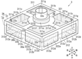
筐体3Aは、フレーム31、及び閉塞体32を備えて、中空の矩形箱状に形成される。筐体3Aの下面には、矩形状の開口が送風口30aとして形成されている。送風口30aは、X-Y平面(X軸及びY軸で規定される平面)に沿った矩形状の平面であり、この送風口30aの軸方向はZ軸に沿った方向となる。
(2.1) Housing The housing 3A is formed in the shape of a hollow rectangular box, and includes a frame 31 and a blocking body 32. A rectangular opening is formed as an air outlet 30a on the bottom surface of the housing 3A. The air outlet 30a is a rectangular flat surface along the XY plane (a plane defined by the X-axis and the Y-axis), and the axial direction of the air outlet 30a is along the Z-axis.

(2.1.1)フレーム
フレーム31は、亜鉛鋼板で形成されており、天板フレーム311、及び枠体フレーム312を備える。
(2.1.1) Frame The frame 31 is formed from a galvanized steel plate, and includes a top plate frame 311 and a frame body frame 312.

(2.1.1.1)天板フレーム
天板フレーム311は、フレーム31の上面に対応する正方形の板状のフレームである。天板フレーム311は、図5Aに示すように、正方形の板金の中央に円形状の挿通孔311aを形成し、挿通孔311aの周囲に4つの同形状の貫通孔311bを形成している。4つの貫通孔311bのそれぞれは、天板フレーム311の四隅のそれぞれから挿通孔311aの手前に至る範囲で形成されている。なお、上述の挿通孔311a及び貫通孔311bは、板金加工又はプレス加工によって生成された肉抜き孔であることが好ましい。
(2.1.1.1) Tabletop Frame The tabletop frame 311 is a square plate-shaped frame corresponding to the upper surface of the frame 31. As shown in Fig. 5A, the tabletop frame 311 has a circular insertion hole 311a formed in the center of the square sheet metal, and four through holes 311b of the same shape formed around the insertion hole 311a. Each of the four through holes 311b is formed in a range extending from each of the four corners of the tabletop frame 311 to just before the insertion hole 311a. The above-mentioned insertion holes 311a and through holes 311b are preferably lightening holes formed by sheet metal processing or press processing.

上述の挿通孔311a及び貫通孔311bを形成された天板フレーム311は、四辺を有する正方形状の矩形枠311cと、矩形枠311cの内側に形成された梁部311dとを一体に備える。梁部311dは、矩形枠311cの各辺を互いに連結するほぼ+形状に形成されている。 The top frame 311, which has the insertion holes 311a and through holes 311b described above, is integrally provided with a square rectangular frame 311c having four sides and a beam portion 311d formed inside the rectangular frame 311c. The beam portion 311d is formed in a substantially + shape that connects each side of the rectangular frame 311c to each other.

梁部311dは、円環板状の円環部311e、及び円環部311eと矩形枠311cとを連結する連結部311fを一体に備える。円環部311eは、矩形枠311cの中央に位置して、挿通孔311aを囲む。すなわち、円環部311eの内側が挿通孔311aとなる。連結部311fは、円環部311eの外周縁と矩形枠311cの4つの辺の各中央とを90度間隔で連結している。貫通孔311bは、円環部311eと、連結部311fと、矩形枠311cとで囲まれている。この結果、4つの貫通孔311bは、X軸に沿った左右方向及びY軸に沿った前後方向に並んだ格子状に形成される。 The beam portion 311d is integrally provided with an annular plate-shaped annular portion 311e and a connecting portion 311f that connects the annular portion 311e and the rectangular frame 311c. The annular portion 311e is located at the center of the rectangular frame 311c and surrounds the insertion hole 311a. In other words, the inside of the annular portion 311e becomes the insertion hole 311a. The connecting portion 311f connects the outer periphery of the annular portion 311e to the center of each of the four sides of the rectangular frame 311c at 90 degree intervals. The through hole 311b is surrounded by the annular portion 311e, the connecting portion 311f, and the rectangular frame 311c. As a result, the four through holes 311b are formed in a lattice pattern arranged in the left-right direction along the X axis and the front-rear direction along the Y axis.

(2.1.1.2)枠体フレーム
枠体フレーム312は、フレーム31の側面(左面、右面、前面、後面)に対応する矩形枠状のフレームであり、板金を折り曲げて形成されている。枠体フレーム312の上端は、天板フレーム311の周縁にカシメ又はねじ止めなどによって取り付けられる。
(2.1.1.2) Frame The frame 312 is a rectangular frame corresponding to the side surfaces (left, right, front, and rear) of the frame 31, and is formed by bending a metal plate. The upper end of the frame 312 is attached to the periphery of the top plate frame 311 by caulking or screwing.

枠体フレーム312の4つの面のそれぞれには、図5Bに示すように、2つの矩形状の貫通孔312aが、枠体フレーム312の周方向に並んで形成されている。すなわち、4つの面を有する枠体フレーム312は、8つの矩形状の貫通孔312aを備える。なお、上述の貫通孔312aは、板金加工又はプレス加工によって生成された肉抜き孔であることが好ましい。 As shown in FIG. 5B, two rectangular through holes 312a are formed side by side in the circumferential direction of the frame 312 on each of the four sides of the frame 312. That is, the frame 312 having four sides has eight rectangular through holes 312a. Note that the above-mentioned through holes 312a are preferably lightening holes created by sheet metal processing or press processing.

上述の貫通孔312aを形成された枠体フレーム312は、枠体フレーム312の各面の外周に沿って形成されている矩形枠312b、及び矩形枠312bの上下方向に対向する2辺の各中央を連結している矩形状の梁部312cを一体に備える。 The frame 312 in which the above-mentioned through holes 312a are formed is integrally provided with a rectangular frame 312b formed along the outer periphery of each face of the frame 312, and a rectangular beam portion 312c connecting the centers of two opposing sides of the rectangular frame 312b in the vertical direction.

枠体フレーム312の上面及び下面は開口している。そして、枠体フレーム312の矩形枠312bの下辺から枠体フレーム312の内側に向かって、正方形の枠状の鍔部312dが延びている。鍔部312dは、板金を折り曲げ加工することで、矩形枠312bに一体に形成されることが好ましい。鍔部312dによって四辺を囲まれた枠体フレーム312の下面の開口が、筐体3Aの送風口30aとなる。 The top and bottom of the frame 312 are open. A square frame-shaped flange 312d extends from the bottom edge of the rectangular frame 312b of the frame 312 toward the inside of the frame 312. The flange 312d is preferably formed integrally with the rectangular frame 312b by bending a metal plate. The opening on the bottom of the frame 312, surrounded on all four sides by the flange 312d, becomes the air outlet 30a of the housing 3A.

(2.1.2)閉塞体
閉塞体32は、天板パネル321、及び枠体パネル322を備える。
(2.1.2) Closure Body The closure body 32 includes a top panel 321 and a frame panel 322 .

天板パネル321は、平板部321a、給気口321b、及び筒体321cを備える。 The top panel 321 has a flat portion 321a, an air intake port 321b, and a cylindrical body 321c.

平板部321a及び給気口321bは、硬質発泡スチロールで一体に形成されている。具体的に、平板部321aは、閉塞体32の上面に対応する正方形の板状のパネルであり、天板フレーム311の貫通孔311bを塞ぐ。平板部321aの中央には、両端を開口した円筒状の給気口321bが形成されている。 The flat plate portion 321a and the air supply port 321b are integrally formed from hard polystyrene foam. Specifically, the flat plate portion 321a is a square plate-shaped panel that corresponds to the upper surface of the blocking body 32 and closes the through hole 311b of the top plate frame 311. A cylindrical air supply port 321b with both ends open is formed in the center of the flat plate portion 321a.

筒体321cは、ポリプロピレン(PP:polypropylene)樹脂で形成された円筒状の筒体である。筒体321cは、給気口321bに対して同軸に位置するように、給気口321bにインサート成形されている。筒体321cの外径は給気口321bの外径より小さく、筒体321cの外周面が給気口321bの内周面に接している。筒体321cの上端は、給気口321bの上端より上方に突出している。筒体321cの下端の外周面には、円環状の鍔部321d(図3参照)が一体に設けられており、鍔部321dは、筒体321cが給気口321bから抜けることを防止する抜け止めとして機能する。そして、筒体321cの上端側はダクト5の端部に嵌め込まれる(図3参照)。 The cylinder 321c is a cylindrical cylinder made of polypropylene (PP) resin. The cylinder 321c is insert-molded into the air inlet 321b so as to be coaxial with the air inlet 321b. The outer diameter of the cylinder 321c is smaller than that of the air inlet 321b, and the outer circumferential surface of the cylinder 321c is in contact with the inner circumferential surface of the air inlet 321b. The upper end of the cylinder 321c protrudes upward from the upper end of the air inlet 321b. A circular flange 321d (see FIG. 3) is integrally formed on the outer circumferential surface of the lower end of the cylinder 321c, and the flange 321d functions as a stopper that prevents the cylinder 321c from coming off the air inlet 321b. The upper end side of the cylinder 321c is fitted into the end of the duct 5 (see FIG. 3).

枠体パネル322は、硬質発泡スチロールで形成されて、閉塞体32の側面(左面、右面、前面、後面)に対応する正方形状の枠体であり、左面、右面、前面、後面のそれぞれ対応する4つの側壁322aを備える。枠体パネル322は、枠体フレーム312の貫通孔312aを塞ぐ。枠体パネル322の上端は、天板パネル321の下面に密着する。 The frame panel 322 is made of hard polystyrene foam and is a square frame that corresponds to the side surfaces (left, right, front, and rear) of the closure body 32, and has four side walls 322a that correspond to the left, right, front, and rear surfaces. The frame panel 322 closes the through hole 312a of the frame frame 312. The upper end of the frame panel 322 is in close contact with the lower surface of the top panel 321.

(2.2)整流板
整流板3Bは、ポリプロピレン(polypropylene)を材料とする樹脂成型によって、正方形の平板状に形成されている。
(2.2) Straightening Plate The straightening plate 3B is formed in a square flat plate shape by resin molding using polypropylene as a material.

整流板3Bは、厚み方向に対向する第1面33a及び第2面33bを備えて、筐体3A内に配置される。整流板3Bの四隅には、円柱状の支持体33cの下端がそれぞれ取り付けられており、支持体33cが、天板フレーム311の矩形枠311cに固定される。 The straightening plate 3B has a first surface 33a and a second surface 33b that face each other in the thickness direction, and is disposed within the housing 3A. The lower ends of cylindrical supports 33c are attached to the four corners of the straightening plate 3B, and the supports 33c are fixed to the rectangular frame 311c of the top plate frame 311.

(2.3)送風装置
送風装置3では、筐体3A及び整流板3Bが以下のように組み合わされる。
(2.3) Blower Device In the blower device 3, the housing 3A and the air straightening plate 3B are combined as follows.

天板パネル321は、天板パネル321の上面が天板フレーム311の下面に接するように、天板フレーム311に対して配置される。すなわち、天板フレーム311の貫通孔311bは、天板パネル321によって塞がれる。このとき、天板パネル321の給気口321bは、天板フレーム311の挿通孔311aを下から上に向かって挿通し、給気口321b及び筒体321cは、天板フレーム311より上方に突出する。 The top panel 321 is positioned relative to the top frame 311 so that the upper surface of the top panel 321 is in contact with the lower surface of the top frame 311. That is, the through hole 311b of the top frame 311 is blocked by the top panel 321. At this time, the air intake 321b of the top panel 321 is inserted from bottom to top through the insertion hole 311a of the top frame 311, and the air intake 321b and the cylinder 321c protrude upward from the top frame 311.

整流板3Bは、天板パネル321の下方に位置し、整流板3Bの4つの支持体33cの各上端は、天板パネル321の四隅の各挿通孔(図示なし)を通って、矩形枠311cの四隅の各固定部311g(図5参照)に、ねじ又はカシメなどによって固定される。このとき、天板パネル321の平板部321aが、支持体33cと天板フレーム311との間に挟み込まれることが好ましい。 The straightening plate 3B is located below the top panel 321, and the upper ends of the four supports 33c of the straightening plate 3B pass through the insertion holes (not shown) at the four corners of the top panel 321 and are fixed to the fixing parts 311g (see FIG. 5) at the four corners of the rectangular frame 311c by screws, rivets, or the like. At this time, it is preferable that the flat part 321a of the top panel 321 is sandwiched between the supports 33c and the top frame 311.

枠体パネル322の上端は、天板パネル321の下面に、圧着、接着、溶着、又はねじ止めなどによって取り付けられる。すなわち、天板パネル321と枠体パネル322とで、矩形箱状の閉塞体32が構成され、枠体パネル322の上面開口は、天板パネル321によって覆われる。 The upper end of the frame panel 322 is attached to the underside of the top panel 321 by crimping, gluing, welding, screwing, or the like. In other words, the top panel 321 and the frame panel 322 form a rectangular box-shaped closure 32, and the top opening of the frame panel 322 is covered by the top panel 321.

枠体フレーム312には、枠体フレーム312の内周面が枠体パネル322の外周面に接するように、枠体パネル322が上方から嵌め込まれる。すなわち、枠体フレーム312の貫通孔312aは、枠体パネル322によって塞がれる。枠体フレーム312の上端は、天板フレーム311の周縁にカシメ又はねじ止めなどによって取り付けられる。 The frame panel 322 is fitted from above into the frame frame 312 so that the inner peripheral surface of the frame frame 312 contacts the outer peripheral surface of the frame panel 322. In other words, the through hole 312a of the frame frame 312 is blocked by the frame panel 322. The upper end of the frame frame 312 is attached to the periphery of the top frame 311 by caulking or screwing.

また、枠体パネル322の下端は、枠体フレーム312の鍔部312dの上面に当接する。枠体パネル322の下面開口は、鍔部312dによって狭められ、鍔部312dの内側の正方形の開口が送風口30aとなる。このように、送風口30aの周縁には、絞り部を構成する鍔部312dが形成される。絞り部は、内部空間30bを送風口30aの周縁に向かって狭めるように、内部空間30bの送風口30a側の部位を絞る。絞り部の一例である鍔部312dは、矩形枠312bの下端から送風口30aに向かって、X-Y平面に沿って鍔状に延びている。すなわち、鍔部312dは、送風口30aの周縁から矩形枠312bの下端に至る。 The lower end of the frame panel 322 abuts against the upper surface of the flange 312d of the frame frame 312. The lower opening of the frame panel 322 is narrowed by the flange 312d, and the square opening inside the flange 312d becomes the air outlet 30a. In this way, the flange 312d constituting the narrowing portion is formed on the periphery of the air outlet 30a. The narrowing portion narrows the part of the internal space 30b on the air outlet 30a side so as to narrow the internal space 30b toward the periphery of the air outlet 30a. The flange 312d, which is an example of a narrowing portion, extends in a flange-like shape along the X-Y plane from the bottom end of the rectangular frame 312b toward the air outlet 30a. In other words, the flange 312d reaches from the periphery of the air outlet 30a to the bottom end of the rectangular frame 312b.

そして、天板パネル321及び枠体パネル322で囲まれた空間を筐体3Aの内部空間30bとすると、内部空間30bには整流板3Bが収納されている。整流板3Bの第1面(上面)33aは、天板パネル321に対向し、整流板3Bの第2面(下面)33bは、送風口30aに対向している。 The space surrounded by the top panel 321 and the frame panel 322 is the internal space 30b of the housing 3A, and the air straightening plate 3B is housed in the internal space 30b. The first surface (upper surface) 33a of the air straightening plate 3B faces the top panel 321, and the second surface (lower surface) 33b of the air straightening plate 3B faces the air outlet 30a.

枠体パネル322の側壁322aの内面と整流板3Bの周縁との間には、連通部30c(図3参照)を構成する隙間が生じている。すなわち、整流板3Bの外側には、内部空間30bにおいて第1面33a側の空間と第2面33b側の空間とを連続させる連通部30cが形成されている。 A gap that forms a communication section 30c (see FIG. 3) is formed between the inner surface of the side wall 322a of the frame panel 322 and the periphery of the straightening plate 3B. In other words, a communication section 30c is formed on the outside of the straightening plate 3B, which connects the space on the first surface 33a side to the space on the second surface 33b side in the internal space 30b.

そして、チャンバ装置4からダクト5に流し込まれた第1空気A1は、ダクト5から筒体321c及び給気口321bを通って、筐体3Aの内部空間30bに供給される。給気口321bから内部空間30bに上から下に向かって供給された第1空気A1は、整流板3Bの第1面33aに沿って流れ、連通部30cを上から下に向かって通過した後、整流板3Bの第2面33bと鍔部312dとの間を送風口30aに向かって進み、送風口30aから下方へ吹き出す。 Then, the first air A1 flowing into the duct 5 from the chamber device 4 is supplied from the duct 5 through the cylinder 321c and the air supply port 321b to the internal space 30b of the housing 3A. The first air A1 supplied from the air supply port 321b from top to bottom into the internal space 30b flows along the first surface 33a of the straightening plate 3B, passes from top to bottom through the communication portion 30c, and then travels between the second surface 33b of the straightening plate 3B and the flange portion 312d toward the air outlet 30a, and is blown out downward from the air outlet 30a.

送風口30aの周縁には、鍔部312dが形成されている。送風装置3は、送風口30aの周縁に鍔部312dを備えることで、鍔部312dを備えていない場合に比べて、送風口30aから吹き出す第1空気A1を指向性気流とすることができる。すなわち、鍔部312dは、送風口30aから吹き出す第1空気A1の指向性を高める機能を有しており、送風装置3は、送風口30aから吹き出す第1空気A1を狭い範囲に集中させることができる。言い換えると、第1空気A1は、狙った領域にのみを到達し、周囲への拡散性が低くなる。 A flange 312d is formed on the periphery of the air outlet 30a. By providing the flange 312d on the periphery of the air outlet 30a, the air blower 3 can make the first air A1 blown out from the air outlet 30a a directional airflow, compared to when the flange 312d is not provided. In other words, the flange 312d has the function of increasing the directionality of the first air A1 blown out from the air outlet 30a, and the air blower 3 can concentrate the first air A1 blown out from the air outlet 30a in a narrow range. In other words, the first air A1 reaches only the targeted area, and is less likely to diffuse to the surroundings.

上述の送風装置3は、亜鉛鋼板を肉抜き加工することで、貫通孔311b及び312aを有するフレーム31を備える。すなわち、フレーム31は、亜鉛鋼板を用いることで強度を確保しながら、肉抜き加工によって軽量化を実現している。また、閉塞体32は、硬質発泡スチロールで形成されることで、軽量化及び強度確保を図っている。そして、筐体3Aではフレーム31が閉塞体32の外面を覆っており、筐体3Aの軽量化及び強度確保の両方が実現される。したがって、筐体3Aを用いている送風装置3は、軽量化と強度の確保との両立を実現することができる。 The above-mentioned blower 3 is provided with a frame 31 having through holes 311b and 312a formed by hollowing out a zinc steel plate. That is, the frame 31 is made of zinc steel plate to ensure strength, while being lightweight due to hollowing out. The blocking body 32 is made of hard polystyrene foam to ensure both weight reduction and strength. In the housing 3A, the frame 31 covers the outer surface of the blocking body 32, realizing both weight reduction and strength of the housing 3A. Therefore, the blower 3 using the housing 3A can achieve both weight reduction and strength.

この結果、送風装置3の施工及び取付時の負担が抑えられ,上述のチャンバ装置4などの付加装置を追加しやすくなる。 As a result, the burden of constructing and installing the air blower 3 is reduced, making it easier to add additional equipment such as the chamber device 4 described above.

また、天井91に埋込配設された送風装置3は、天井91の例えば枠体に支持される。したがって、図3に示すように、ダクト5を、フレーム31ではなく閉塞体32に接続しても、閉塞体32に過大な荷重が加えられることはない。 The blower 3 embedded in the ceiling 91 is supported by, for example, a frame of the ceiling 91. Therefore, as shown in FIG. 3, even if the duct 5 is connected to the obstruction body 32 instead of the frame 31, excessive load is not applied to the obstruction body 32.

また、枠体フレーム312のみで十分な強度を確保できるのであれば、フレーム31は、天板フレーム311を備えていなくてもよい。 In addition, if sufficient strength can be ensured with only the frame body frame 312, the frame 31 does not need to include the top plate frame 311.

(3)第1変形例
第1変形例の送風装置3-1を図6に示す。送風装置3-1は、駆動機構34を備える。駆動機構34は、電動アクチュエータ34a、及びサポートガイド34bを備える。
(3) First Modification A blower 3-1 of a first modification is shown in Fig. 6. The blower 3-1 includes a drive mechanism 34. The drive mechanism 34 includes an electric actuator 34a and a support guide 34b.

電動アクチュエータ34aは、筐体3Aの上面の前側に取り付けられている。電動アクチュエータ34aは、電動モータ、X軸に沿って左右方向に延びるボールねじ、ボールねじに嵌め込まれているねじナット、及びねじナットに取り付けられているロッドを備える。電動モータの回転力はボールねじに伝達され、ボールねじは、ボールねじの軸を回転軸として回転する。ねじナットは、ボールねじが一方に回転するとX軸に沿って左方向に移動し、ボールねじが他方に回転するとX軸に沿って右方向に移動する。ねじナットにはロッドが取り付けられており、ロッドも、ねじナットと同様にボールねじの回転に応じてX軸に沿って移動する。 The electric actuator 34a is attached to the front side of the top surface of the housing 3A. The electric actuator 34a includes an electric motor, a ball screw extending left and right along the X-axis, a screw nut fitted into the ball screw, and a rod attached to the screw nut. The rotational force of the electric motor is transmitted to the ball screw, and the ball screw rotates around the axis of the ball screw as its rotation axis. The screw nut moves left along the X-axis when the ball screw rotates in one direction, and moves right along the X-axis when the ball screw rotates in the other direction. A rod is attached to the screw nut, and the rod also moves along the X-axis in response to the rotation of the ball screw, just like the screw nut.

筐体3Aの上面には、電動アクチュエータ34aに対向してX軸に沿って延びる図示しない開口が形成されている。電動アクチュエータ34aのロッドには、少なくとも1つの棒状の第1支持体の上端が接続されている。第1支持体の下端は、筐体3Aの開口を通って内部空間30bに挿入され、整流板3Bに取り付けられている。 An opening (not shown) is formed on the top surface of the housing 3A, facing the electric actuator 34a and extending along the X-axis. The upper end of at least one rod-shaped first support is connected to the rod of the electric actuator 34a. The lower end of the first support is inserted into the internal space 30b through the opening in the housing 3A and is attached to the straightening plate 3B.

サポートガイド34bは、筐体3Aの上面の後側に取り付けられている。サポートガイド34bは、直線状のレール、及びレールに取り付けられているスライダを備える。レールは、X軸に沿って左右方向に延びるように取り付けられている。スライダは、レールに沿って左右方向にリニアに移動する。すなわち、レールの延設方向は、電動アクチュエータ34aの変位方向と同じになる。筐体3Aの上面には、サポートガイド34bに対向してX軸に沿って延びる図示しない開口が形成されている。サポートガイド34bのスライダには、少なくとも1つの棒状の第2支持体の上端が接続されている。第2支持体の下端は、筐体3Aの開口を通って内部空間30bに挿入され、整流板3Bに取り付けられている。 The support guide 34b is attached to the rear side of the upper surface of the housing 3A. The support guide 34b has a linear rail and a slider attached to the rail. The rail is attached so as to extend in the left-right direction along the X-axis. The slider moves linearly in the left-right direction along the rail. In other words, the extension direction of the rail is the same as the displacement direction of the electric actuator 34a. An opening (not shown) is formed on the upper surface of the housing 3A, facing the support guide 34b and extending along the X-axis. The upper end of at least one rod-shaped second support is connected to the slider of the support guide 34b. The lower end of the second support is inserted into the internal space 30b through the opening of the housing 3A and is attached to the straightening plate 3B.

コントローラK1(図1参照)は、電動アクチュエータ34aの位置制御を行う。すなわち、電動アクチュエータ34aのロッドの位置は、コントローラK1によって制御される。 The controller K1 (see FIG. 1) controls the position of the electric actuator 34a. That is, the position of the rod of the electric actuator 34a is controlled by the controller K1.

駆動機構34は、内部空間30bにおける閉塞体32の左面と整流板3Bの左端との間に形成された隙間である連通部、及び閉塞体32の右面と整流板3Bの右端との間に形成された隙間である連通部を変化させるように、整流板3BをX軸に沿う左右方向にスライドさせる。そして、送風装置3-1は、整流板3Bのスライド位置が変化することで、送風口30aから吹き出す第1空気A1の指向性を制御することができる。 The drive mechanism 34 slides the straightening plate 3B in the left-right direction along the X-axis so as to change the communicating portion, which is the gap formed between the left surface of the obstruction body 32 and the left end of the straightening plate 3B in the internal space 30b, and the communicating portion, which is the gap formed between the right surface of the obstruction body 32 and the right end of the straightening plate 3B. The blower 3-1 can control the directionality of the first air A1 blown out from the air outlet 30a by changing the sliding position of the straightening plate 3B.

送風装置3-1では、筐体3Aの上面に駆動機構34を取り付けるため、フレーム31は、上述の送風装置3の天板フレーム311の代わりに、天板フレーム311Aを備える。天板フレーム311Aには、駆動機構34の重量に耐えうる強度を確保するとともに、軽量化を図ることが求められる。 In the blower 3-1, in order to attach the drive mechanism 34 to the top surface of the housing 3A, the frame 31 is provided with a top plate frame 311A instead of the top plate frame 311 of the blower 3 described above. The top plate frame 311A is required to have a strength sufficient to withstand the weight of the drive mechanism 34 while also being lightweight.

そこで、天板フレーム311Aは、図6に示すように、正方形の板金の中央に形成されている円形状の挿通孔311aの周囲に、4つの貫通孔311h、及び4つの貫通孔311iを形成している。なお、上述の貫通孔311h及び貫通孔311iは、板金加工又はプレス加工によって生成された肉抜き孔であることが好ましい。 As shown in FIG. 6, the top frame 311A has four through holes 311h and four through holes 311i formed around a circular insertion hole 311a formed in the center of a square metal sheet. It is preferable that the above-mentioned through holes 311h and 311i are lightening holes created by metal sheet processing or press processing.

4つの貫通孔311hは、挿通孔311aを挟んで2行2列に配置されている。すなわち、4つの貫通孔311hのうち、2つの貫通孔311hは、挿通孔311aを挟んで他の2つの貫通孔311hとX軸に沿った左右方向に対向している。貫通孔311hは、ほぼ矩形状であり、挿通孔311aに対向する1つの辺は、挿通孔311aの周縁に沿う円弧状となっている。 The four through holes 311h are arranged in two rows and two columns, sandwiching the insertion hole 311a between them. In other words, of the four through holes 311h, two through holes 311h face the other two through holes 311h in the left-right direction along the X-axis, sandwiching the insertion hole 311a between them. The through holes 311h are substantially rectangular, and one side facing the insertion hole 311a is an arc shape that follows the periphery of the insertion hole 311a.

4つの貫通孔311iのうち2つの貫通孔311iは、天板フレーム311Aの前辺に沿って並び、他の2つの貫通孔311iは、天板フレーム311Aの後辺に沿って並んでいる。貫通孔311iは、X軸に沿った左右方向に長い矩形状である。 Of the four through holes 311i, two through holes 311i are aligned along the front edge of the tabletop frame 311A, and the other two through holes 311i are aligned along the rear edge of the tabletop frame 311A. The through holes 311i are rectangular and elongated in the left-right direction along the X-axis.

上述の挿通孔311a、貫通孔311h、311iを形成された天板フレーム311Aは、四辺を有する正方形状の矩形枠311cと、矩形枠311cの内側に形成された梁部311jとを一体に備える。梁部311jは、矩形枠311cの各辺を互いに連結する格子状に形成されている。 The top frame 311A, which is formed with the above-mentioned insertion holes 311a and through holes 311h and 311i, is integrally provided with a square rectangular frame 311c having four sides and a beam portion 311j formed inside the rectangular frame 311c. The beam portion 311j is formed in a lattice shape that connects each side of the rectangular frame 311c to each other.

具体的に、梁部311jは、円環板状の円環部311e、連結部311kを一体に備える。円環部311eは、矩形枠311cの中央に位置して、挿通孔311aを囲む。連結部311kは、円環部311eの外周縁と矩形枠311cの左辺及び右辺の各中央とを180度間隔で連結している。さらに、連結部311kは、矩形枠311cの左辺と右辺との間を直接に連結している。さらに、連結部311kは、Y軸に沿った前後方向にも延びている。 Specifically, the beam portion 311j is integral with the annular plate-shaped annular portion 311e and the connecting portion 311k. The annular portion 311e is located at the center of the rectangular frame 311c and surrounds the insertion hole 311a. The connecting portion 311k connects the outer periphery of the annular portion 311e to the centers of the left and right sides of the rectangular frame 311c at 180 degree intervals. Furthermore, the connecting portion 311k directly connects the left and right sides of the rectangular frame 311c. Furthermore, the connecting portion 311k also extends in the front-rear direction along the Y axis.

連結部311kには電動アクチュエータ34a及びサポートガイド34bが取り付けられている。すなわち、連結部311kには、電動アクチュエータ34aに対向してX軸に沿って延びる図示しない挿通孔が、電動アクチュエータ34aの第1支持体が挿通する孔として形成されている。また、連結部311kには、サポートガイド34bに対向してX軸に沿って延びる図示しない挿通孔が、サポートガイド34bの第2支持体が挿通する孔として形成されている。 The electric actuator 34a and the support guide 34b are attached to the connecting portion 311k. That is, the connecting portion 311k has an insertion hole (not shown) that extends along the X-axis facing the electric actuator 34a and is formed as a hole through which the first support of the electric actuator 34a passes. In addition, the connecting portion 311k has an insertion hole (not shown) that extends along the X-axis facing the support guide 34b and is formed as a hole through which the second support of the support guide 34b passes.

上述のように、送風装置3-1のコントローラK1は、整流板3Bの位置制御(電動アクチュエータ34aの位置制御)を行う。このとき、コントローラK1は、外部信号を受け取り、この外部信号に基づいて整流板3Bの位置制御を行うことが好ましい。すなわち、コントローラK1は、外部信号に応じて、整流板3Bのスライド位置を、内部空間30bの左右方向の中央、内部空間30bの左右方向の右側、又は内部空間30bの左右方向の左側に調整することができる。なお、整流板3Bのスライド位置は、内部空間30bの中央、右側、左側の3段階ではなく、4段階以上、又は無段階に連続的に変位可能であってもよい。 As described above, the controller K1 of the blower 3-1 controls the position of the straightening vane 3B (position control of the electric actuator 34a). At this time, it is preferable that the controller K1 receives an external signal and controls the position of the straightening vane 3B based on this external signal. That is, the controller K1 can adjust the slide position of the straightening vane 3B to the center in the left-right direction of the internal space 30b, the right side in the left-right direction of the internal space 30b, or the left side in the left-right direction of the internal space 30b in response to the external signal. Note that the slide position of the straightening vane 3B may be displaceable in four or more steps, or continuously in an infinitely stepless manner, instead of in three steps of the center, right side, and left side of the internal space 30b.

外部信号は、例えば、空調空間9の壁面に設置されている操作装置が出力する信号である。操作装置は、管理人によって操作される押し釦、スライドつまみ、及びタッチパネルなどの少なくとも1つを操作部として備え、操作部は、整流板3Bのスライド位置に対応する操作を施される。そして、操作装置は、操作部の操作に応じた外部信号をコントローラK1に出力する。この場合、管理人が空調空間9に存在する人の位置に応じて操作部を操作する。すなわち、送風装置3-1は、操作装置の手動操作によって、空調空間9内の人毎に快適な空調環境を生成することができる。 The external signal is, for example, a signal output by an operating device installed on a wall of the air-conditioned space 9. The operating device has at least one of a push button, a sliding knob, a touch panel, etc., operated by the caretaker as an operating unit, and the operating unit is operated corresponding to the sliding position of the air straightening plate 3B. The operating device then outputs an external signal corresponding to the operation of the operating unit to the controller K1. In this case, the caretaker operates the operating unit according to the position of the person present in the air-conditioned space 9. In other words, the air blower 3-1 can generate a comfortable air-conditioned environment for each person in the air-conditioned space 9 by manually operating the operating device.

また、外部信号は、例えば、空調空間9に設置されている人体検知センサが出力する信号であってもよい。人体検知センサは、赤外線センサ、カメラ画像センサ、又は熱画像センサなどを含み、空調空間9内の人の位置を検出し、当該検出結果を外部信号としてコントローラK1に出力する。この場合、コントローラK1は、空調空間9内の人の位置に応じて整流板3Bのスライド位置を自動制御する。すなわち、送風装置3-1は、人体検知センサを用いた自動制御によって、空調空間9内の人毎に快適な空調環境を生成することができる。 The external signal may also be, for example, a signal output by a human body detection sensor installed in the air-conditioned space 9. The human body detection sensor includes an infrared sensor, a camera image sensor, a thermal image sensor, or the like, and detects the position of a person in the air-conditioned space 9 and outputs the detection result to the controller K1 as an external signal. In this case, the controller K1 automatically controls the sliding position of the straightening plate 3B according to the position of the person in the air-conditioned space 9. In other words, the blower 3-1 can generate a comfortable air-conditioned environment for each person in the air-conditioned space 9 through automatic control using the human body detection sensor.

(4)第2変形例
上述の第1変形例の送風装置3-1において、天板フレーム311Aの代わりに、図7に示す天板フレーム311Bを備えてもよい。
(4) Second Modification In the blower device 3-1 of the first modification described above, a top plate frame 311B shown in FIG. 7 may be provided instead of the top plate frame 311A.

天板フレーム311Bは、正方形の板金の中央に形成されている円形状の挿通孔311aの周囲に、2つの同形状の貫通孔311m、及び4つの同形状の貫通孔311nを形成している。なお、上述の貫通孔311m及び貫通孔311nは、板金加工又はプレス加工によって生成された肉抜き孔であることが好ましい。 The top frame 311B has two identically shaped through holes 311m and four identically shaped through holes 311n around a circular insertion hole 311a formed in the center of a square metal sheet. It is preferable that the above-mentioned through holes 311m and 311n are lightening holes created by metal sheet processing or press processing.

2つの貫通孔311mは、挿通孔311aを挟んでX軸に沿った左右方向に互いに対向している。貫通孔311mは、Y軸に沿った前後方向に長い矩形状である。 The two through holes 311m face each other in the left-right direction along the X-axis, sandwiching the insertion hole 311a therebetween. The through hole 311m is rectangular and elongated in the front-rear direction along the Y-axis.

4つの貫通孔311nのうち2つの貫通孔311nは、天板フレーム311Bの前辺に沿って並び、他の2つの貫通孔311nは、天板フレーム311Bの後辺に沿って並んでいる。貫通孔311nは、X軸に沿った左右方向に長い矩形状である。 Of the four through holes 311n, two through holes 311n are aligned along the front edge of the tabletop frame 311B, and the other two through holes 311n are aligned along the rear edge of the tabletop frame 311B. The through holes 311n are rectangular and elongated in the left-right direction along the X-axis.

上述の挿通孔311a、貫通孔311m、311nを形成された天板フレーム311Bは、四辺を有する正方形状の矩形枠311cと、矩形枠311cの内側に形成された梁部311oとを一体に備える。梁部311oは、矩形枠311cの各辺を互いに連結する格子状に形成されている。 The top frame 311B, which is formed with the above-mentioned insertion holes 311a and through holes 311m and 311n, is integrally provided with a square rectangular frame 311c having four sides and a beam portion 311o formed inside the rectangular frame 311c. The beam portion 311o is formed in a lattice shape that connects each side of the rectangular frame 311c to each other.

電動アクチュエータ34aは、天板フレーム311Bの上面において、前側の貫通孔311nと挿通孔311aとの間に、左右方向に沿って取り付けられている。天板フレーム311Bには、電動アクチュエータ34aに対向してX軸に沿って延びる図示しない挿通孔が、電動アクチュエータ34aの第1支持体が挿通する孔として形成されている。 The electric actuator 34a is attached in the left-right direction on the top surface of the tabletop frame 311B between the front through-hole 311n and the insertion hole 311a. The tabletop frame 311B has an insertion hole (not shown) that faces the electric actuator 34a and extends along the X-axis, through which the first support of the electric actuator 34a is inserted.

サポートガイド34bは、天板フレーム311Bの上面において、後側の貫通孔311nと挿通孔311aとの間に、左右方向に沿って取り付けられている。天板フレーム311Bには、サポートガイド34bに対向してX軸に沿って延びる図示しない挿通孔が、サポートガイド34bの第2支持体が挿通する孔として形成されている。 The support guide 34b is attached in the left-right direction on the top surface of the tabletop frame 311B between the rear through-hole 311n and the insertion hole 311a. The tabletop frame 311B has an insertion hole (not shown) that faces the support guide 34b and extends along the X-axis, through which the second support of the support guide 34b is inserted.

(5)第3変形例
上述の第1変形例の送風装置3-1において、天板フレーム311Aの代わりに、図8に示す天板フレーム311Cを備えてもよい。
(5) Third Modification In the blower device 3-1 of the first modification described above, a top plate frame 311C shown in FIG. 8 may be provided instead of the top plate frame 311A.

天板フレーム311Cは、正方形の板金の中央に形成されている貫通孔311p、及び2つの貫通孔311rを備えている。なお、上述の貫通孔311p及び貫通孔311rは、板金加工又はプレス加工によって生成された肉抜き孔であることが好ましい。 The top frame 311C has a through hole 311p formed in the center of the square metal sheet, and two through holes 311r. Note that the above-mentioned through holes 311p and 311r are preferably lightening holes created by metal sheet processing or press processing.

貫通孔311pは、X軸に沿った左右方向に長い矩形状であり、天板フレーム311Cの前後方向の中央に形成されている。 The through hole 311p is rectangular and elongated in the left-right direction along the X-axis, and is formed in the center of the top frame 311C in the front-rear direction.

2つの貫通孔311rは、貫通孔311pを挟んでY軸に沿った前後方向に互いに対向している。貫通孔311rは、X軸に沿った左右方向に長い矩形状である。 The two through holes 311r face each other in the front-to-rear direction along the Y axis, sandwiching the through hole 311p. The through hole 311r has a rectangular shape that is long in the left-to-right direction along the X axis.

上述の貫通孔311p、311rを形成された天板フレーム311Cは、四辺を有する正方形状の矩形枠311cと、矩形枠311cの内側に形成された梁部311sとを一体に備える。梁部311sは、矩形枠311cの左辺及び右辺を互いに連結する梁状に形成されている。 The top frame 311C in which the above-mentioned through holes 311p and 311r are formed is integrally provided with a square rectangular frame 311c having four sides and a beam portion 311s formed inside the rectangular frame 311c. The beam portion 311s is formed in a beam shape that connects the left and right sides of the rectangular frame 311c to each other.

電動アクチュエータ34aは、天板フレーム311Cの上面において、前側の貫通孔311rと貫通孔311pの前辺との間に、左右方向に沿って取り付けられている。天板フレーム311Cには、電動アクチュエータ34aに対向してX軸に沿って延びる図示しない挿通孔が、電動アクチュエータ34aの第1支持体が挿通する孔として形成されている。 The electric actuator 34a is attached in the left-right direction on the top surface of the tabletop frame 311C between the front through-hole 311r and the front edge of the through-hole 311p. The tabletop frame 311C has an insertion hole (not shown) that faces the electric actuator 34a and extends along the X-axis, through which the first support of the electric actuator 34a is inserted.

サポートガイド34bは、天板フレーム311Cの上面において、後側の貫通孔311rと貫通孔311pの後辺との間に、左右方向に沿って取り付けられている。天板フレーム311Cには、サポートガイド34bに対向してX軸に沿って延びる図示しない挿通孔が、サポートガイド34bの第2支持体が挿通する孔として形成されている。 Support guide 34b is attached along the left-right direction on the top surface of tabletop frame 311C between rear through-hole 311r and the rear edge of through-hole 311p. In tabletop frame 311C, an insertion hole (not shown) that faces support guide 34b and extends along the X-axis is formed as a hole through which the second support of support guide 34b is inserted.

(6)気流制御システム
図9は、上述の送風システム1を用いた気流制御システム8を示す。
(6) Airflow Control System FIG. 9 shows an airflow control system 8 using the above-described air blowing system 1.

気流制御システム8は、送風システム1に加えて、複数の床換気装置71、空調設備72、外部通気路2、及び戻し通気路21を備える。 In addition to the air blowing system 1, the airflow control system 8 includes multiple floor ventilation devices 71, air conditioning equipment 72, an external air vent 2, and a return air vent 21.

複数の床換気装置71のそれぞれは、空調空間9の床93に埋込配設されて、空調空間9内の空気を第4空気A4として吸い込む。複数の床換気装置71のそれぞれが吸い込んだ第4空気A4は、戻し通気路21を通って空調設備72に供給される。気流制御システム8は、複数の床換気装置71を備えることによって、複数の床換気装置71を備えていない場合に比べて、第4空気A4をより強く吸引することができる。この結果、気流制御システム8は、空調空間9における単位時間当たりの換気量を増加させることができ、空調空間9の空気を素早く入れ換えることができる。 Each of the multiple floor ventilation devices 71 is embedded in the floor 93 of the air-conditioned space 9 and draws in the air in the air-conditioned space 9 as the fourth air A4. The fourth air A4 drawn in by each of the multiple floor ventilation devices 71 is supplied to the air conditioning equipment 72 through the return air passage 21. By being provided with multiple floor ventilation devices 71, the airflow control system 8 can draw in the fourth air A4 more strongly than when the multiple floor ventilation devices 71 are not provided. As a result, the airflow control system 8 can increase the amount of ventilation per unit time in the air-conditioned space 9 and quickly replace the air in the air-conditioned space 9.

空調設備72は、第4空気A4の温度、湿度、及び清浄度の少なくとも1つを調整し、第3空気A3として外部通気路2へ送り出す。第3空気A3は、空調設備72で生成された調和空気である。なお、調和空気は、香りの付加又はウイルス量の低減が施された空気であってもよい。 The air conditioning equipment 72 adjusts at least one of the temperature, humidity, and cleanliness of the fourth air A4, and sends it to the external air passage 2 as the third air A3. The third air A3 is conditioned air generated by the air conditioning equipment 72. The conditioned air may be air to which a fragrance has been added or to which the amount of viruses has been reduced.

送風システム1は、空調空間9内の空気を第2空気A2として吸い込む。さらに、送風システム1は、空調設備72から外部通気路2を介して送り出された第3空気A3を受け取る。そして、送風システム1は、第2空気A2と第3空気A3とを混合した空気を第1空気A1として、空調空間9内に吹き出す。 The air supply system 1 draws in the air in the air-conditioned space 9 as the second air A2. Furthermore, the air supply system 1 receives the third air A3 sent out from the air conditioning equipment 72 via the external air passage 2. The air supply system 1 then blows the mixture of the second air A2 and the third air A3 into the air-conditioned space 9 as the first air A1.

特に、上述の第1変形例~第3変形例のいずれかの送風装置3-1を備える送風システム1は、第1空気A1を指向性気流として、その指向性を制御することで、一人(又は少人数)の人が存在する狭い範囲に集中して、温度、湿度、清浄度、香り、ウイルス量の少なくとも1つが調整された第1空気A1を吹き出すことができる。すなわち、空調空間9内における空調のゾーン制御を行う際に、各ゾーンを狭くし、狭いゾーン毎に空気質を調整することが可能になる。また、空調空間9内のゾーンの位置を変化させることも可能になる。この結果、気流制御システム8は、空調空間9内の人H1、H2のそれぞれに、人H1、H2毎の快適な空調環境を提供できる。 In particular, the air blowing system 1 equipped with the air blowing device 3-1 of any of the first to third modified examples described above can blow out the first air A1, which has been adjusted in at least one of the temperature, humidity, cleanliness, fragrance, and virus quantity, by controlling the directionality of the first air A1 as a directional airflow and concentrating it in a small area where one (or a small number of) people are present. In other words, when controlling the air conditioning zones in the air-conditioned space 9, it becomes possible to narrow each zone and adjust the air quality for each narrow zone. It also becomes possible to change the position of the zones in the air-conditioned space 9. As a result, the airflow control system 8 can provide a comfortable air-conditioned environment for each person H1, H2 in the air-conditioned space 9.

ここで、上述の第1変形例~第3変形例では、図9において送風システム1が右側の人H2に送っている第1空気A1の向きは、整流板3Bが左右方向のほぼ中央に位置している第一状態に相当する。また、図9において送風システム1が左側の人H1に送っている第1空気A1の向きは、整流板3Bが左右方向のほぼ中央でなく左右方向のいずれか片側に位置する第二状態に相当している。これら整流板3Bの第一状態と第二状態との切替制御は、空調空間9の壁面に設置されている操作装置による手動制御、及び空調空間9に設置されている人体検知センサ(赤外線センサ、カメラ画像センサ、又は熱画像センサなど)を用いた自動制御のいずれであってもよい。人体検知センサは、送風システム1に対する人H1、H2の位置(送風システム1の直下、右側、左側など)を検出する。 Here, in the first to third modified examples described above, the direction of the first air A1 sent by the air blowing system 1 to the person H2 on the right side in FIG. 9 corresponds to a first state in which the straightening vane 3B is located approximately in the center in the left-right direction. Also, the direction of the first air A1 sent by the air blowing system 1 to the person H1 on the left side in FIG. 9 corresponds to a second state in which the straightening vane 3B is located on either the left or right side, not approximately in the center in the left-right direction. The switching control of the straightening vane 3B between the first state and the second state may be either manual control by an operating device installed on the wall surface of the air-conditioned space 9, or automatic control using a human body detection sensor (such as an infrared sensor, a camera image sensor, or a thermal image sensor) installed in the air-conditioned space 9. The human body detection sensor detects the positions of the people H1 and H2 relative to the air blowing system 1 (directly below, to the right, or to the left of the air blowing system 1, etc.).

また、整流板3Bの自動制御には、空調空間9の入室時に認証処理を行う図示しない認証システムを用いてもよい。認証システムは、例えばカードリーダ、又は生体認証装置などを用いて空調空間9内への人の入室の可否を判定し、空調空間9における入室及び退室の管理を行う。送風システム1は、認証システムの認証結果を用いて整流板3Bの自動制御を行う。例えば、認証システムによって空調空間9への入室を許可された人H1、H2と、人H1、H2のそれぞれの座席の位置と、各座席の近傍の送風システム1とを組にして互いに対応付ける。そして、送風システム1は、人H1、H2の各座席に第1空気A1が向かうように、各送風システム1の整流板3Bの位置を制御する。 The automatic control of the straightening vane 3B may be performed using an authentication system (not shown) that performs authentication processing when entering the air-conditioned space 9. The authentication system uses, for example, a card reader or a biometric authentication device to determine whether or not a person can enter the air-conditioned space 9, and manages entry and exit to the air-conditioned space 9. The air supply system 1 automatically controls the straightening vane 3B using the authentication result of the authentication system. For example, the persons H1 and H2 who are permitted to enter the air-conditioned space 9 by the authentication system, the positions of the seats of the persons H1 and H2, and the air supply systems 1 near each seat are paired and associated with each other. The air supply system 1 then controls the position of the straightening vane 3B of each air supply system 1 so that the first air A1 is directed toward each seat of the persons H1 and H2.

このとき、送風システム1は、人H1、H2のそれぞれの好みの空気質のデータを予め保持しており、人H1、H2のそれぞれの好みの空気質を、各送風システム1が吹き出す第1空気A1に反映させることが好ましい。すなわち、送風システム1は、人H1、H2の各個人の好みの空気質となるように、各送風システム1が吹き出す第1空気A1の質を個別制御する。例えば、人H1は、冷え性のため冷気でなく暖気を好み、しかも好みの香りによるリラックスを所望している。そこで、人H1の近傍の送風システム1は、人H1の好みの香りを含む暖気を第1空気A1として送風する。また、人H2は、冬季などのように空調空間9内の気温が例えば25度以下であれば、空気質に対して要望はない。しかし、人H2は、暑がりであるため、夏季などのように空調空間9内の気温が例えば25度を上回れば、温度24度以下の冷気、かつ、ドライ風を所望している。そこで、人H2の近傍の送風システム1は、空調空間9内の気温が25度を上回れば、人H2の好みの24度以下の冷気、かつ、ドライ風を第1空気A1として送風する。このような空気質の制御は、送風システム1のコンピュータが予め作成されたプログラムを実行することで実現される。 At this time, it is preferable that the air supply system 1 holds data on the preferred air quality of each of the persons H1 and H2 in advance, and that the preferred air quality of each of the persons H1 and H2 is reflected in the first air A1 blown out by each air supply system 1. That is, the air supply system 1 individually controls the quality of the first air A1 blown out by each air supply system 1 so that the air quality is the preferred air quality of each of the persons H1 and H2. For example, person H1 prefers warm air rather than cold air because he is prone to cold, and also wants to relax with a favorite scent. Therefore, the air supply system 1 near person H1 blows warm air containing person H1's favorite scent as the first air A1. Furthermore, person H2 has no preference regarding air quality if the temperature in the air-conditioned space 9 is, for example, 25 degrees or lower, such as in winter. However, person H2 is sensitive to heat, and therefore desires cool air at a temperature of 24 degrees or less and dry air when the temperature in the air-conditioned space 9 exceeds 25 degrees, for example, as in the summer. Therefore, when the temperature in the air-conditioned space 9 exceeds 25 degrees, the air blowing system 1 near person H2 blows cool air at a temperature of 24 degrees or less and dry air, which is person H2's preference, as the first air A1. This type of air quality control is achieved by the computer of the air blowing system 1 executing a program created in advance.

また、空調空間9内の送風システム1が1台だけであれば、1台の送風システム1は、人H1、H2の2名に対して、以下のように第1空気A1を制御する。送風システム1は、人H1、H2の2名に第1空気A1を送風するとき、第1空気A1の送風方向を、時系列上で交互に、人H1に所定時間だけ向けたあと、人H2に同じく所定時間だけ向け、また人H1に所定時間だけ向ける、という方向切替制御を行う。このとき、上述したように、人H1、H2のぞれぞれの個人の好みを第1空気A1に反映させる個別制御として、人H1、H2のそれぞれの好みの空気質を、第1空気A1に交互に反映させるようにしてもよい。 Furthermore, if there is only one air supply system 1 in the air-conditioned space 9, the single air supply system 1 controls the first air A1 for the two people H1 and H2 as follows. When the air supply system 1 blows the first air A1 to the two people H1 and H2, it performs direction switching control such that the blowing direction of the first air A1 is alternately directed toward person H1 for a predetermined time, then toward person H2 for a predetermined time, and then toward person H1 for a predetermined time again. At this time, as described above, as individual control that reflects the personal preferences of each of people H1 and H2 in the first air A1, the preferred air quality of each of people H1 and H2 may be alternately reflected in the first air A1.

また、1台の送風システム1は、人H1、H2の2名に対して、第1空気A1の送風方向を切り替える方向切替制御を行わずに、第1空気A1の送風方向を固定してもよい。この場合、送風システム1は、人H1、H2の2名に共通する好みの空気質だけを第1空気A1に反映させればよい。あるいは、人H1、H2の2名に共通する好みの空気質がなければ、予め決められた標準的な空気質を第1空気A1に反映させてもよい。 In addition, one air blowing system 1 may fix the blowing direction of the first air A1 for the two people H1 and H2, without performing direction switching control to switch the blowing direction of the first air A1. In this case, the air blowing system 1 may reflect only the preferred air quality common to the two people H1 and H2 in the first air A1. Alternatively, if there is no preferred air quality common to the two people H1 and H2, a predetermined standard air quality may be reflected in the first air A1.

(7)他の変形例
フレーム31は、亜鉛鋼板以外の金属、例えばアルミニウム、鉄、又はステンレス鋼などの他の金属で形成されてもよい。
(7) Other Modifications The frame 31 may be formed of a metal other than galvanized steel, for example, aluminum, iron, stainless steel, or other metal.

閉塞体32は、硬質発泡スチロール以外の樹脂、又は木材などのように、フレーム31より密度の低い材料で形成されてもよい。 The obstruction body 32 may be made of a material with a lower density than the frame 31, such as a resin other than hard polystyrene foam or wood.

送風口30aの周縁には、鍔部312dが絞り部として形成されているが、絞り部は、鍔部312dに限定されない。絞り部は、内部空間30bを送風口30aの周縁に向かって狭めるように、内部空間30bの送風口30a側の部位を絞る構成を備えていればよい。例えば、絞り部は、内部空間30bを送風口30aの周縁に向かって下方に進むにつれて徐々に狭める形状としてもよい。 A flange 312d is formed as a narrowing portion on the periphery of the air outlet 30a, but the narrowing portion is not limited to the flange 312d. The narrowing portion may have a configuration that narrows the portion of the internal space 30b on the air outlet 30a side so as to narrow the internal space 30b toward the periphery of the air outlet 30a. For example, the narrowing portion may be shaped to gradually narrow the internal space 30b as it progresses downward toward the periphery of the air outlet 30a.

整流板3Bは1枚の板部材であるが、整流板3Bの代わりに、複数の板部材を整流板として用いてもよい。 The straightening plate 3B is a single plate member, but multiple plate members may be used as the straightening plate instead of the straightening plate 3B.

また、上述の第1変形例~第3変形例の送風装置3-1において、整流板3Bのスライド方向は、X軸に沿った左右方向に限定されない。すなわち、整流板3Bのスライド方向は、X-Y平面上の仮想的な線分に沿った方向、例えばY軸に沿った前後方向であってもよい。また、整流板3Bのスライド方向は、Z軸に直交する方向に限定されず、Z軸に交差する方向であればよい。 In addition, in the blower device 3-1 of the first to third modified examples described above, the sliding direction of the straightening vane 3B is not limited to the left-right direction along the X-axis. In other words, the sliding direction of the straightening vane 3B may be a direction along an imaginary line segment on the X-Y plane, for example, a front-rear direction along the Y-axis. In addition, the sliding direction of the straightening vane 3B is not limited to a direction perpendicular to the Z-axis, and may be any direction that intersects with the Z-axis.

また、送風システム1が取り付けられる構造体は天井91に限定されず、空調空間の上方に設けられた架台などの他の構造体であってもよい。 In addition, the structure to which the air blowing system 1 is attached is not limited to the ceiling 91, but may be another structure such as a stand installed above the air-conditioned space.

また、駆動機構34は、電動アクチュエータ34aの代わりに、空気圧アクチュエータ又は油圧アクチュエータなどの他のアクチュエータを用いてもよい。 In addition, the drive mechanism 34 may use other actuators, such as a pneumatic actuator or a hydraulic actuator, instead of the electric actuator 34a.

(8)まとめ
上述の実施形態に係る第1の態様の送風装置(3)は、筐体(3A)と、整流板(3B)と、を備える。筐体(3A)は、内部空間(30b)を有する箱状に形成されており、内部空間(30b)に空気を送り込むための給気口(321b)、及び内部空間(30b)の外部に空気を吐き出すための送風口(30a)を有する。整流板(3B)は、給気口(321b)と送風口(30a)との間に配置されている。筐体(3A)は、金属で形成され、少なくとも1つの貫通孔(311b、311h、311i、311m、311n、311p、311r、312a)を有しているフレーム(31)と、樹脂で形成され、フレーム(31)の少なくとも1つの貫通孔(311b、311h、311i、311m、311n、311p、311r、312a)を塞ぐ閉塞体(32)と、を有する。
(8) Summary The blower device (3) of the first aspect according to the above embodiment includes a housing (3A) and a straightening vane (3B). The housing (3A) is formed in a box shape having an internal space (30b), and has an air inlet (321b) for feeding air into the internal space (30b) and an air outlet (30a) for discharging air to the outside of the internal space (30b). The straightening vane (3B) is disposed between the air inlet (321b) and the air outlet (30a). The housing (3A) has a frame (31) formed of metal and having at least one through hole (311b, 311h, 311i, 311m, 311n, 311p, 311r, 312a), and a blocking body (32) formed of resin and blocking the at least one through hole (311b, 311h, 311i, 311m, 311n, 311p, 311r, 312a) of the frame (31).

上述の送風装置(3)は、軽量化と強度の確保との両立を実現することができる。 The above-mentioned blower device (3) can achieve both lightweight construction and strength.

上述の実施形態に係る第2の態様の送風装置(3)は、第1の態様において、貫通孔(311b、311h、311i、311m、311n、311p、311r、312a)を複数備えることが好ましい。 In the first aspect, the blower device (3) of the second aspect of the embodiment described above preferably has a plurality of through holes (311b, 311h, 311i, 311m, 311n, 311p, 311r, 312a).

上述の送風装置(3)は、更なる軽量化を図ることができる。 The above-mentioned blower device (3) can be made even lighter.

上述の実施形態に係る第3の態様の送風装置(3)は、第2の態様において、複数の貫通孔(311b、311h、311i、311m、311n、311p、311r、312a)は、少なくとも1つの方向に沿って並んでいることが好ましい。 In the third aspect of the blower device (3) according to the above-mentioned embodiment, in the second aspect, it is preferable that the multiple through holes (311b, 311h, 311i, 311m, 311n, 311p, 311r, 312a) are aligned along at least one direction.

上述の送風装置(3)は、複数の貫通孔(311b、311h、311i、311m、311n、311p、311r)によって形成された梁部が格子状になって、フレーム(31)の強度を確保しやすくなる。 The above-mentioned air blower (3) has a lattice-like beam formed by multiple through holes (311b, 311h, 311i, 311m, 311n, 311p, 311r), which makes it easier to ensure the strength of the frame (31).

上述の実施形態に係る第4の態様の送風装置(3)は、第1乃至第3の態様のいずれか1つにおいて、フレーム(31)は、少なくとも1つの貫通孔(311b、311h、311i、311m、311n、311p、311r、312a)を形成された金属板を備えることが好ましい。 In the fourth aspect of the blower device (3) according to the above-mentioned embodiment, in any one of the first to third aspects, the frame (31) preferably comprises a metal plate having at least one through hole (311b, 311h, 311i, 311m, 311n, 311p, 311r, 312a) formed therein.

上述の送風装置(3)は、フレーム(31)の強度を確保しやすくなる。 The above-mentioned blower device (3) makes it easier to ensure the strength of the frame (31).

上述の実施形態に係る第5の態様の送風装置(3)は、第4の態様において、金属板は、亜鉛鋼板であることが好ましい。 In the fifth aspect of the blower device (3) according to the above-mentioned embodiment, in the fourth aspect, it is preferable that the metal plate is a galvanized steel plate.

上述の送風装置(3)は、フレーム(31)の強度を確保しやすくなる。 The above-mentioned blower device (3) makes it easier to ensure the strength of the frame (31).

上述の実施形態に係る第6の態様の送風装置(3)は、第1乃至第5の態様のいずれか1つにおいて、閉塞体(32)は、樹脂として硬質発泡スチロールを用いて形成されていることが好ましい。 In the sixth aspect of the blower device (3) according to the above-mentioned embodiment, in any one of the first to fifth aspects, it is preferable that the obstruction body (32) is formed using hard polystyrene foam as the resin.

上述の送風装置(3)は、閉塞体(32)の軽量化と強度の確保との両立を実現することができる。 The above-mentioned blower device (3) can achieve both weight reduction and strength of the obstruction body (32).

上述の実施形態に係る第7の態様の送風装置(3)は、第1乃至第6の態様のいずれか1つにおいて、整流板(3B)を移動させる駆動機構(34)を更に備えることが好ましい。 The seventh aspect of the blower device (3) according to the above embodiment is preferably any one of the first to sixth aspects, further comprising a drive mechanism (34) for moving the straightening vane (3B).

上述の送風装置(3)は、吹き出す空気の指向性を制御することができる。 The above-mentioned blower device (3) can control the directionality of the air being blown out.

上述の実施形態に係る第8の態様の送風システム(1)は、送風口(30a)から空調空間(9)へ空気として第1空気(A1)を吐き出第1乃至第7のいずれか1つの送風装置(3)と、チャンバ装置(4)と、を備える。チャンバ装置(4)は、空調空間(9)の空気を第2空気(A2)として吸い込み、外部からの空気を第3空気(A3)として吸い込み、第2空気(A2)と第3空気(A3)とを混合した空気を第1空気(A1)として生成する。 The eighth aspect of the air blowing system (1) according to the above embodiment includes any one of the first to seventh air blowing devices (3) that blows out the first air (A1) as air from the air outlet (30a) into the air-conditioned space (9), and a chamber device (4). The chamber device (4) draws in air from the air-conditioned space (9) as the second air (A2), draws in air from the outside as the third air (A3), and generates a mixture of the second air (A2) and the third air (A3) as the first air (A1).

上述の送風システム(1)は、送風装置(3)の軽量化と強度の確保との両立を実現することができる。 The above-mentioned air blowing system (1) can achieve both weight reduction and strength of the air blowing device (3).

上述の実施形態に係る第9の態様の送風システム(1)は、第8の態様において、第1空気(A1)は、調和空気を含むことが好ましい。 In the ninth aspect of the ventilation system (1) according to the above-mentioned embodiment, in the eighth aspect, it is preferable that the first air (A1) includes conditioned air.

上述の送風システム(1)は、空気質を調整することができる。 The above-mentioned ventilation system (1) can adjust the air quality.

1 送風システム
3 送風装置
3A 筐体
3B 整流板
30a 送風口
30b 内部空間
31 フレーム
311b、311h、311i、311m、311n、311p、311r、312a 貫通孔
32 閉塞体
321b 給気口
34 駆動機構
4 チャンバ装置
9 空調空間
A1 第1空気
A2 第2空気
A3 第3空気
REFERENCE SIGNS LIST 1 Air blowing system 3 Air blowing device 3A Housing 3B Straightening plate 30a Air blowing port 30b Internal space 31 Frame 311b, 311h, 311i, 311m, 311n, 311p, 311r, 312a Through hole 32 Blocking body 321b Air supply port 34 Driving mechanism 4 Chamber device 9 Air-conditioned space A1 First air A2 Second air A3 Third air

Claims (8)

内部空間を有する箱状に形成されており、前記内部空間に空気を送り込むための給気口、及び前記内部空間の外部である空調空間に前記空気を吐き出すための送風口を有する筐体と、
前記給気口と前記送風口との間に配置されている整流板と、
前記整流板を、前記送風口の軸方向と交差する方向に移動させる駆動機構と、
を備え、
前記筐体は、
金属で形成され、少なくとも1つの貫通孔を有しているフレームと、
樹脂で形成され、前記フレームの前記少なくとも1つの貫通孔を塞ぐ閉塞体と、を有し、
前記駆動機構は、前記整流板を前記交差する方向に移動させる電動アクチュエータを有する
送風装置。
a housing formed in a box shape having an internal space, the housing having an air intake port for feeding air into the internal space and an air outlet for discharging the air into an air-conditioned space outside the internal space;
A rectifying plate disposed between the air inlet and the air outlet;
a drive mechanism that moves the air straightening plate in a direction intersecting an axial direction of the air outlet ;
Equipped with
The housing includes:
a frame formed of metal and having at least one through hole;
a blocking body formed of resin and blocking the at least one through hole of the frame,
The driving mechanism includes an electric actuator that moves the baffle plate in the intersecting direction .
前記貫通孔を複数備える
請求項1の送風装置。
The blower device according to claim 1 , comprising a plurality of the through holes.
前記複数の貫通孔は、少なくとも1つの方向に沿って並んでいる
請求項2の送風装置。
The blower device according to claim 2 , wherein the plurality of through holes are aligned along at least one direction.
前記フレームは、前記少なくとも1つの貫通孔を形成された金属板を備える
請求項1乃至3のいずれか1つの送風装置。
The blower device according to claim 1 , wherein the frame comprises a metal plate having the at least one through hole formed therein.
前記金属板は、亜鉛鋼板である
請求項4の送風装置。
The blower device according to claim 4 , wherein the metal plate is a galvanized steel plate.
前記閉塞体は、前記樹脂として硬質発泡スチロールを用いて形成されている
請求項1乃至5のいずれか1つの送風装置。
The air blower according to claim 1 , wherein the blocking body is formed by using hard expanded polystyrene as the resin.
前記送風口から空調空間へ前記空気として第1空気を吐き出す請求項1乃至6のいずれか1つの送風装置と、
前記空調空間の空気を第2空気として吸い込み、外部からの空気を第3空気として吸い込み、前記第2空気と前記第3空気とを混合した空気を前記第1空気として生成するチャンバ装置と、を備える
送風システム。
a blower device according to any one of claims 1 to 6, which blows out a first air as the air from the blower port into an air-conditioned space;
a chamber device that draws in air in the air-conditioned space as second air, draws in air from the outside as third air, and generates air that is a mixture of the second air and the third air as the first air.
前記第1空気は、調和空気を含む
請求項7の送風システム。
The ventilation system of claim 7 , wherein the first air comprises conditioned air.
JP2020182625A 2020-10-30 2020-10-30 Blower and Blower System Active JP7617552B2 (en)

Priority Applications (1)

Application Number Priority Date Filing Date Title
JP2020182625A JP7617552B2 (en) 2020-10-30 2020-10-30 Blower and Blower System

Applications Claiming Priority (1)

Application Number Priority Date Filing Date Title
JP2020182625A JP7617552B2 (en) 2020-10-30 2020-10-30 Blower and Blower System

Publications (2)

Publication Number Publication Date
JP2022072922A JP2022072922A (en) 2022-05-17
JP7617552B2 true JP7617552B2 (en) 2025-01-20

Family

ID=81604097

Family Applications (1)

Application Number Title Priority Date Filing Date
JP2020182625A Active JP7617552B2 (en) 2020-10-30 2020-10-30 Blower and Blower System

Country Status (1)

Country Link
JP (1) JP7617552B2 (en)

Families Citing this family (2)

* Cited by examiner, † Cited by third party
Publication number Priority date Publication date Assignee Title
JP7620912B2 (en) * 2020-10-30 2025-01-24 パナソニックIpマネジメント株式会社 Blower and Blower System
WO2024014147A1 (en) * 2022-07-15 2024-01-18 パナソニックIpマネジメント株式会社 Blower device and blower system

Citations (6)

* Cited by examiner, † Cited by third party
Publication number Priority date Publication date Assignee Title
JP2000039204A (en) 1998-07-24 2000-02-08 Fujimori Sangyo Kk Chamber for mounting outlet and method of construction
JP2001141258A (en) 1999-08-30 2001-05-25 Mitsubishi Heavy Ind Ltd Method for manufacturing cabinet for air conditioner
JP2001174041A (en) 1999-12-14 2001-06-29 Takenaka Komuten Co Ltd Air outlet with box
JP2002122349A (en) 2000-10-16 2002-04-26 Kyoritsu Air Tech Inc Air flow control device for air outlet
JP2016070620A (en) 2014-09-30 2016-05-09 三機工業株式会社 Pneumatic radiation air conditioner and air conditioning system using the same
JP2020079669A (en) 2018-11-12 2020-05-28 株式会社シロハチ Desktop type ventilation booth and manufacturing kit thereof

Family Cites Families (2)

* Cited by examiner, † Cited by third party
Publication number Priority date Publication date Assignee Title
JPH05288378A (en) * 1992-04-03 1993-11-02 Hitachi Plant Eng & Constr Co Ltd Clean room
JP3103696B2 (en) * 1992-12-22 2000-10-30 松下精工株式会社 Air blower for air conditioning

Patent Citations (6)

* Cited by examiner, † Cited by third party
Publication number Priority date Publication date Assignee Title
JP2000039204A (en) 1998-07-24 2000-02-08 Fujimori Sangyo Kk Chamber for mounting outlet and method of construction
JP2001141258A (en) 1999-08-30 2001-05-25 Mitsubishi Heavy Ind Ltd Method for manufacturing cabinet for air conditioner
JP2001174041A (en) 1999-12-14 2001-06-29 Takenaka Komuten Co Ltd Air outlet with box
JP2002122349A (en) 2000-10-16 2002-04-26 Kyoritsu Air Tech Inc Air flow control device for air outlet
JP2016070620A (en) 2014-09-30 2016-05-09 三機工業株式会社 Pneumatic radiation air conditioner and air conditioning system using the same
JP2020079669A (en) 2018-11-12 2020-05-28 株式会社シロハチ Desktop type ventilation booth and manufacturing kit thereof

Also Published As

Publication number Publication date
JP2022072922A (en) 2022-05-17

Similar Documents

Publication Publication Date Title
JP5664644B2 (en) Air conditioner and control circuit
JP5678953B2 (en) Air conditioner and control circuit
JP7617552B2 (en) Blower and Blower System
JP6160806B2 (en) Air conditioner and control circuit
CN117109078A (en) Air conditioning device
JPWO2017175749A1 (en) Indoor air conditioning system
JP6052519B2 (en) Air conditioner and control circuit
JP2020517889A (en) Air conditioner indoor unit
JPH08100946A (en) Grille for diffusion air-conditioning
JP6182882B2 (en) Air conditioner
JP7503774B2 (en) Blower and Blower System
JPH08303849A (en) Air conditioner
JP4879854B2 (en) Air conditioner
JP2010270958A (en) Air conditioner indoor unit
JP7620912B2 (en) Blower and Blower System
US7896319B2 (en) Sauna apparatus
JP6079963B2 (en) Air conditioner and control circuit
JPH07310943A (en) Underfloor air conditioner system
JP4729874B2 (en) Air conditioner
JPH042861B2 (en)
JP2008304129A (en) Radiant air conditioning system
JP7072164B2 (en) Floor outlet device
JP6164395B2 (en) Air conditioner and control circuit
JP2021196095A (en) Air conditioner and ventilation air-conditioning system
JP6164394B2 (en) Air conditioner and control circuit

Legal Events

Date Code Title Description
A621 Written request for application examination

Free format text: JAPANESE INTERMEDIATE CODE: A621

Effective date: 20230807

A977 Report on retrieval

Free format text: JAPANESE INTERMEDIATE CODE: A971007

Effective date: 20240315

A131 Notification of reasons for refusal

Free format text: JAPANESE INTERMEDIATE CODE: A131

Effective date: 20240319

A521 Request for written amendment filed

Free format text: JAPANESE INTERMEDIATE CODE: A523

Effective date: 20240520

A131 Notification of reasons for refusal

Free format text: JAPANESE INTERMEDIATE CODE: A131

Effective date: 20240730

A601 Written request for extension of time

Free format text: JAPANESE INTERMEDIATE CODE: A601

Effective date: 20240930

A521 Request for written amendment filed

Free format text: JAPANESE INTERMEDIATE CODE: A523

Effective date: 20241021

TRDD Decision of grant or rejection written
A01 Written decision to grant a patent or to grant a registration (utility model)

Free format text: JAPANESE INTERMEDIATE CODE: A01

Effective date: 20241126

A61 First payment of annual fees (during grant procedure)

Free format text: JAPANESE INTERMEDIATE CODE: A61

Effective date: 20241220

R150 Certificate of patent or registration of utility model

Ref document number: 7617552

Country of ref document: JP

Free format text: JAPANESE INTERMEDIATE CODE: R150