JP7610552B2 - Heat Treatment System - Google Patents
Heat Treatment System Download PDFInfo
- Publication number
- JP7610552B2 JP7610552B2 JP2022143096A JP2022143096A JP7610552B2 JP 7610552 B2 JP7610552 B2 JP 7610552B2 JP 2022143096 A JP2022143096 A JP 2022143096A JP 2022143096 A JP2022143096 A JP 2022143096A JP 7610552 B2 JP7610552 B2 JP 7610552B2
- Authority
- JP
- Japan
- Prior art keywords
- sagger
- hood
- heat treatment
- opening
- recovery
- Prior art date
- Legal status (The legal status is an assumption and is not a legal conclusion. Google has not performed a legal analysis and makes no representation as to the accuracy of the status listed.)
- Active
Links
- 238000010438 heat treatment Methods 0.000 title claims description 78
- 238000011084 recovery Methods 0.000 claims description 112
- 230000007246 mechanism Effects 0.000 claims description 39
- 230000007723 transport mechanism Effects 0.000 claims description 29
- 238000003780 insertion Methods 0.000 claims description 2
- 230000037431 insertion Effects 0.000 claims description 2
- 230000032258 transport Effects 0.000 description 107
- 239000000463 material Substances 0.000 description 40
- 239000000843 powder Substances 0.000 description 23
- 238000005516 engineering process Methods 0.000 description 17
- 238000004140 cleaning Methods 0.000 description 11
- 238000001514 detection method Methods 0.000 description 11
- 239000000428 dust Substances 0.000 description 6
- 230000005540 biological transmission Effects 0.000 description 4
- 238000012423 maintenance Methods 0.000 description 3
- 239000000126 substance Substances 0.000 description 3
- 238000011109 contamination Methods 0.000 description 2
- 238000010586 diagram Methods 0.000 description 2
- HBBGRARXTFLTSG-UHFFFAOYSA-N Lithium ion Chemical compound [Li+] HBBGRARXTFLTSG-UHFFFAOYSA-N 0.000 description 1
- 230000007423 decrease Effects 0.000 description 1
- 239000012634 fragment Substances 0.000 description 1
- 229910001416 lithium ion Inorganic materials 0.000 description 1
- 238000012986 modification Methods 0.000 description 1
- 230000004048 modification Effects 0.000 description 1
- 239000007774 positive electrode material Substances 0.000 description 1
- 238000007789 sealing Methods 0.000 description 1
- 238000011144 upstream manufacturing Methods 0.000 description 1
Images


Classifications
-
- F—MECHANICAL ENGINEERING; LIGHTING; HEATING; WEAPONS; BLASTING
- F27—FURNACES; KILNS; OVENS; RETORTS
- F27B—FURNACES, KILNS, OVENS OR RETORTS IN GENERAL; OPEN SINTERING OR LIKE APPARATUS
- F27B9/00—Furnaces through which the charge is moved mechanically, e.g. of tunnel type; Similar furnaces in which the charge moves by gravity
- F27B9/14—Furnaces through which the charge is moved mechanically, e.g. of tunnel type; Similar furnaces in which the charge moves by gravity characterised by the path of the charge during treatment; characterised by the means by which the charge is moved during treatment
- F27B9/20—Furnaces through which the charge is moved mechanically, e.g. of tunnel type; Similar furnaces in which the charge moves by gravity characterised by the path of the charge during treatment; characterised by the means by which the charge is moved during treatment the charge moving in a substantially straight path
- F27B9/26—Furnaces through which the charge is moved mechanically, e.g. of tunnel type; Similar furnaces in which the charge moves by gravity characterised by the path of the charge during treatment; characterised by the means by which the charge is moved during treatment the charge moving in a substantially straight path on or in trucks, sleds, or containers
- F27B9/262—Furnaces through which the charge is moved mechanically, e.g. of tunnel type; Similar furnaces in which the charge moves by gravity characterised by the path of the charge during treatment; characterised by the means by which the charge is moved during treatment the charge moving in a substantially straight path on or in trucks, sleds, or containers on or in trucks
-
- F—MECHANICAL ENGINEERING; LIGHTING; HEATING; WEAPONS; BLASTING
- F27—FURNACES; KILNS; OVENS; RETORTS
- F27B—FURNACES, KILNS, OVENS OR RETORTS IN GENERAL; OPEN SINTERING OR LIKE APPARATUS
- F27B9/00—Furnaces through which the charge is moved mechanically, e.g. of tunnel type; Similar furnaces in which the charge moves by gravity
- F27B9/14—Furnaces through which the charge is moved mechanically, e.g. of tunnel type; Similar furnaces in which the charge moves by gravity characterised by the path of the charge during treatment; characterised by the means by which the charge is moved during treatment
- F27B9/20—Furnaces through which the charge is moved mechanically, e.g. of tunnel type; Similar furnaces in which the charge moves by gravity characterised by the path of the charge during treatment; characterised by the means by which the charge is moved during treatment the charge moving in a substantially straight path
- F27B9/24—Furnaces through which the charge is moved mechanically, e.g. of tunnel type; Similar furnaces in which the charge moves by gravity characterised by the path of the charge during treatment; characterised by the means by which the charge is moved during treatment the charge moving in a substantially straight path being carried by a conveyor
-
- F—MECHANICAL ENGINEERING; LIGHTING; HEATING; WEAPONS; BLASTING
- F27—FURNACES; KILNS; OVENS; RETORTS
- F27B—FURNACES, KILNS, OVENS OR RETORTS IN GENERAL; OPEN SINTERING OR LIKE APPARATUS
- F27B9/00—Furnaces through which the charge is moved mechanically, e.g. of tunnel type; Similar furnaces in which the charge moves by gravity
- F27B9/30—Details, accessories or equipment specially adapted for furnaces of these types
- F27B9/38—Arrangements of devices for charging
-
- F—MECHANICAL ENGINEERING; LIGHTING; HEATING; WEAPONS; BLASTING
- F27—FURNACES; KILNS; OVENS; RETORTS
- F27B—FURNACES, KILNS, OVENS OR RETORTS IN GENERAL; OPEN SINTERING OR LIKE APPARATUS
- F27B9/00—Furnaces through which the charge is moved mechanically, e.g. of tunnel type; Similar furnaces in which the charge moves by gravity
- F27B9/30—Details, accessories or equipment specially adapted for furnaces of these types
- F27B9/39—Arrangements of devices for discharging
-
- F—MECHANICAL ENGINEERING; LIGHTING; HEATING; WEAPONS; BLASTING
- F27—FURNACES; KILNS; OVENS; RETORTS
- F27B—FURNACES, KILNS, OVENS OR RETORTS IN GENERAL; OPEN SINTERING OR LIKE APPARATUS
- F27B9/00—Furnaces through which the charge is moved mechanically, e.g. of tunnel type; Similar furnaces in which the charge moves by gravity
- F27B9/30—Details, accessories or equipment specially adapted for furnaces of these types
- F27B9/40—Arrangements of controlling or monitoring devices
-
- F—MECHANICAL ENGINEERING; LIGHTING; HEATING; WEAPONS; BLASTING
- F27—FURNACES; KILNS; OVENS; RETORTS
- F27D—DETAILS OR ACCESSORIES OF FURNACES, KILNS, OVENS OR RETORTS, IN SO FAR AS THEY ARE OF KINDS OCCURRING IN MORE THAN ONE KIND OF FURNACE
- F27D25/00—Devices or methods for removing incrustations, e.g. slag, metal deposits, dust; Devices or methods for preventing the adherence of slag
-
- F—MECHANICAL ENGINEERING; LIGHTING; HEATING; WEAPONS; BLASTING
- F27—FURNACES; KILNS; OVENS; RETORTS
- F27D—DETAILS OR ACCESSORIES OF FURNACES, KILNS, OVENS OR RETORTS, IN SO FAR AS THEY ARE OF KINDS OCCURRING IN MORE THAN ONE KIND OF FURNACE
- F27D3/00—Charging; Discharging; Manipulation of charge
- F27D3/12—Travelling or movable supports or containers for the charge
-
- F—MECHANICAL ENGINEERING; LIGHTING; HEATING; WEAPONS; BLASTING
- F27—FURNACES; KILNS; OVENS; RETORTS
- F27B—FURNACES, KILNS, OVENS OR RETORTS IN GENERAL; OPEN SINTERING OR LIKE APPARATUS
- F27B9/00—Furnaces through which the charge is moved mechanically, e.g. of tunnel type; Similar furnaces in which the charge moves by gravity
- F27B9/30—Details, accessories or equipment specially adapted for furnaces of these types
- F27B9/38—Arrangements of devices for charging
- F27B2009/382—Charging
-
- F—MECHANICAL ENGINEERING; LIGHTING; HEATING; WEAPONS; BLASTING
- F27—FURNACES; KILNS; OVENS; RETORTS
- F27B—FURNACES, KILNS, OVENS OR RETORTS IN GENERAL; OPEN SINTERING OR LIKE APPARATUS
- F27B9/00—Furnaces through which the charge is moved mechanically, e.g. of tunnel type; Similar furnaces in which the charge moves by gravity
- F27B9/30—Details, accessories or equipment specially adapted for furnaces of these types
- F27B9/38—Arrangements of devices for charging
- F27B2009/384—Discharging
Landscapes
- Engineering & Computer Science (AREA)
- Mechanical Engineering (AREA)
- General Engineering & Computer Science (AREA)
- Tunnel Furnaces (AREA)
- Furnace Charging Or Discharging (AREA)
- Battery Electrode And Active Subsutance (AREA)
Description
本明細書に開示する技術は、被処理物を熱処理する技術に関する。 The technology disclosed in this specification relates to a technology for heat treating a workpiece.
熱処理炉(例えば、ローラーハースキルンやプッシャーキルン等)を用いて、被処理物を熱処理することがある。例えば、粉体等の被処理物を熱処理炉で熱処理する際には、被処理物は匣鉢に収容された状態で熱処理される。熱処理後には、匣鉢を反転することによって熱処理後の被処理物を回収する。例えば、特許文献1には、熱処理炉と、熱処理後に被処理物を回収する回収装置を備える熱処理システムが開示されている。特許文献1の回収装置は、匣鉢を搬送する搬送ローラと、匣鉢内の被処理物を回収する回収部と、匣鉢を反転するための反転機構を備えている。回収部は、搬送ローラの下方に配置されている。反転機構は、回収部の上方に位置する複数の搬送ローラと、それら搬送ローラに載置されている匣鉢とを一体的に反転させるように構成されている。匣鉢が回収部の上方まで搬送されると、反転機構により、複数の搬送ローラと共に匣鉢が反転する。これにより、匣鉢内の被処理物が落下し、下方に配置されている回収部に被処理物が回収される。
A heat treatment furnace (e.g., a roller hearth kiln, a pusher kiln, etc.) may be used to heat treat the material to be treated. For example, when a material to be treated, such as a powder, is heat treated in a heat treatment furnace, the material is heat treated while contained in a sagger. After the heat treatment, the sagger is inverted to recover the material after the heat treatment. For example,
特許文献1の回収装置では、匣鉢を反転させる際に、匣鉢と共に搬送ローラを回転させている。しかしながら、匣鉢と搬送ローラを一体で回転させると、全体の重量が大きくなるため、回転速度を大きくすることが難しくなる。このため、被処理物の回収に時間を要するという問題があった。
In the recovery device of
本明細書は、熱処理後の被処理物の回収に要する時間を短縮可能な技術を開示する。 This specification discloses a technology that can shorten the time required to recover treated objects after heat treatment.
本明細書に開示する技術の第1の態様では、熱処理システムは、熱処理炉と搬送装置と回収装置と供給装置と、を備えている。熱処理炉は、搬入口と搬出口とを備え、搬入口から搬出口に匣鉢を搬送する間に匣鉢に収容された被処理物を熱処理する。搬送装置は、熱処理炉の搬出口から搬出された匣鉢を熱処理炉の搬入口まで搬送する。回収装置は、搬送装置の搬送経路上に設けられ、熱処理炉で熱処理された被処理物を匣鉢から回収する。供給装置は、搬送装置の搬送経路上であって、回収装置と搬入口との間に設けられ、被処理物が収容されていない匣鉢に、熱処理前の被処理物を供給する。搬送装置は、搬送経路に沿って配置された搬送機構と、搬送機構を駆動する駆動装置と、を備え、駆動装置が搬送機構を駆動することで搬送機構上に載置された匣鉢を搬送するように構成されている。回収装置は、搬送機構が配置されていない位置に設けられ、匣鉢内の被処理物を回収する回収部と、搬送機構上の載置位置と回収部の上方の回収位置との間で匣鉢を移動させる移動装置と、回収位置において匣鉢を反転させる反転機構と、を備えている。 In a first aspect of the technology disclosed in this specification, the heat treatment system includes a heat treatment furnace, a transport device, a recovery device, and a supply device. The heat treatment furnace includes an entrance and an exit, and heat-treats the workpiece contained in the sagger while transporting the sagger from the entrance to the exit. The transport device transports the sagger discharged from the exit of the heat treatment furnace to the entrance of the heat treatment furnace. The recovery device is provided on the transport path of the transport device and recovers the workpiece heat-treated in the heat treatment furnace from the sagger. The supply device is provided on the transport path of the transport device between the recovery device and the entrance, and supplies the workpiece before heat treatment to the sagger not containing the workpiece. The transport device includes a transport mechanism arranged along the transport path and a drive device that drives the transport mechanism, and is configured to transport the sagger placed on the transport mechanism by driving the transport mechanism. The recovery device is provided at a position where the transport mechanism is not located, and includes a recovery section that recovers the material in the sagger, a moving device that moves the sagger between a placement position on the transport mechanism and a recovery position above the recovery section, and an inversion mechanism that inverts the sagger at the recovery position.
上記の熱処理システムでは、回収部を搬送機構が配置されていない位置に配置することによって、匣鉢は反転される前に搬送機構上から回収部の上方に移動される。すなわち、匣鉢は、匣鉢と回収部との間に搬送機構がない状態で反転される。このため、匣鉢を反転する際に、匣鉢と共に搬送機構(例えば、搬送ローラ)を反転する必要がない。これにより、回収部の上方で匣鉢のみを反転することができ、回転する部分全体の重量が大きくなることを回避することができる。このため、回転速度を大きくすることが可能となり、被処理物の回収に要する時間を短くすることが可能となる。 In the above heat treatment system, by locating the recovery section at a position where the transport mechanism is not located, the saggers are moved from above the transport mechanism to above the recovery section before being inverted. In other words, the saggers are inverted without there being a transport mechanism between the saggers and the recovery section. Therefore, when inverting the saggers, it is not necessary to invert the transport mechanism (e.g., transport rollers) together with the saggers. This allows only the saggers to be inverted above the recovery section, and it is possible to avoid increasing the weight of the entire rotating section. This makes it possible to increase the rotation speed and shorten the time required to recover the treated material.
以下に説明する実施例の主要な特徴を列記しておく。なお、以下に記載する技術要素は、それぞれ独立した技術要素であって、単独であるいは各種の組合せによって技術的有用性を発揮するものであり、出願時請求項記載の組合せに限定されるものではない。 The main features of the embodiment described below are listed below. Note that the technical elements described below are independent technical elements that exhibit technical usefulness alone or in various combinations, and are not limited to the combinations described in the claims at the time of filing.
本明細書に開示する技術の第2の態様では、上記の第1の態様において、反転機構は、匣鉢を把持する把持部を備えており、把持部が回転軸周りに回転することで把持部に把持された匣鉢が反転するように構成されていてもよい。移動装置は、把持部で匣鉢を把持した反転機構を搬送機構上の載置位置と回収部の上方の回収位置との間で移動させるように構成されていてもよい。このような構成によると、反転機構は、匣鉢を把持した状態で回収部の上方の回収位置まで移動される。把持部が匣鉢を把持した状態で回転軸周りに回転することで、匣鉢が反転する。このため、匣鉢を回転位置で好適に回転させることができる。 In a second aspect of the technology disclosed in this specification, in the first aspect described above, the inversion mechanism may be configured to include a gripping portion that grips the sagger, and the gripping portion may rotate around a rotation axis to invert the sagger gripped by the gripping portion. The moving device may be configured to move the inversion mechanism gripping the sagger with the gripping portion between a placement position on the transport mechanism and a recovery position above the recovery portion. With this configuration, the inversion mechanism is moved to a recovery position above the recovery portion while gripping the sagger. The gripping portion rotates around the rotation axis while gripping the sagger, thereby inverting the sagger. Therefore, the sagger can be rotated suitably at the rotation position.
本明細書に開示する技術の第3の態様では、上記の第2の態様において、回収装置は、回収部を上方から覆うフードをさらに備えていてもよい。フードは、匣鉢及び把持部を収容可能に構成されていてもよい。匣鉢を把持した把持部が、フードに収容された状態で回転軸周りに回転可能となっていてもよい。このような構成によると、フード内で匣鉢を反転させることによって、匣鉢が反転したときに被処理物がフード外に飛散することを抑制することができる。 In a third aspect of the technology disclosed in this specification, in the second aspect described above, the recovery device may further include a hood that covers the recovery section from above. The hood may be configured to accommodate the sagger and the gripping section. The gripping section that grips the sagger may be rotatable about a rotation axis while being accommodated in the hood. With this configuration, by inverting the sagger within the hood, it is possible to prevent the treated material from scattering outside the hood when the sagger is inverted.
本明細書に開示する技術の第4の態様では、上記の第3の態様において、把持部は、匣鉢の対向する一対の側面に当接して匣鉢を把持する一対の把持片を備えていてもよい。反転機構は、一対の把持片を支持する一対の支持部をさらに備えていてもよい。一対の支持部のそれぞれは、匣鉢及び把持部がフード内に収容されたときに、その一端がフード内に位置する一方でその他端がフード外に位置するように構成されていてもよい。フードは、第1の側面に設けられる第1の開口部と、第1の側面と直交する第2の側面に設けられる第2の開口部と、を備えていてもよい。第1の開口部は、第1の側面から匣鉢をフード内に挿入可能に構成されていてもよい。第2の開口部は、匣鉢をフード内に収容したときに、支持部の他端が第2の開口部からフード外に突出するように構成されていると共に、匣鉢の挿入方向に沿って延びていてもよい。このような構成によると、把持部で匣鉢を把持した状態で、フードの側方(第1の側面)から匣鉢をフード内に収めることができる。 In a fourth aspect of the technology disclosed in this specification, in the third aspect described above, the gripping portion may include a pair of gripping pieces that grip the sack by contacting a pair of opposing side surfaces of the sack. The inversion mechanism may further include a pair of support portions that support the pair of gripping pieces. Each of the pair of support portions may be configured such that, when the sack and the gripping portion are housed in the hood, one end of the support portion is located inside the hood and the other end is located outside the hood. The hood may include a first opening provided on the first side surface and a second opening provided on a second side surface perpendicular to the first side surface. The first opening may be configured to allow the sack to be inserted into the hood from the first side surface. The second opening may be configured such that, when the sack is housed in the hood, the other end of the support portion protrudes outside the hood from the second opening, and may extend along the insertion direction of the sack. With this configuration, the sagger can be placed inside the hood from the side (first side) of the hood while the sagger is held by the gripping portion.
本明細書に開示する技術の第5の態様では、上記の第4の態様において、反転機構は、把持部に把持された匣鉢を前記フード内に収容したときに、第2の開口部を覆う第1のカバーをさらに備えていてもよい。このような構成によると、反転機構に第1のカバーを設けることにより、第1のカバーは反転機構と一体的に移動する。このため、匣鉢をフード内に挿入する際に、支持部が第2の開口部を通過できると共に、匣鉢をフード内に収容した状態では、第1のカバーにより第2の開口部を覆うことができる。これにより、匣鉢をフード内で反転させたときに、第2の開口部から被処理物がフード外に飛散することを抑制することができる。 In a fifth aspect of the technology disclosed in this specification, in the fourth aspect described above, the inversion mechanism may further include a first cover that covers the second opening when the sagger held by the gripping part is housed in the hood. With this configuration, by providing the first cover on the inversion mechanism, the first cover moves integrally with the inversion mechanism. Therefore, when the sagger is inserted into the hood, the support part can pass through the second opening, and when the sagger is housed in the hood, the first cover can cover the second opening. This makes it possible to prevent the treated material from scattering outside the hood from the second opening when the sagger is inverted in the hood.
本明細書に開示する技術の第6の態様では、上記の第4又は第5の態様において、回収装置は、第1の開口部を開閉する第2のカバーをさらに備えていてもよい。第2のカバーが第1の開口部を開いた状態では匣鉢が第1の開口部を通過可能とされ、第2のカバーが第1の開口部を閉じた状態では匣鉢が第1の開口部を通過不能としてもよい。このような構成によると、第2のカバーを設けることにより、匣鉢をフード内に収容したときに、第2のカバーで第1の開口部を覆うことができる。これにより、匣鉢をフード内で反転させたときに、第1の開口部から被処理物がフード外に飛び出すことを抑制することができる。 In a sixth aspect of the technology disclosed in this specification, in the fourth or fifth aspect described above, the recovery device may further include a second cover that opens and closes the first opening. When the second cover opens the first opening, the sagger may be able to pass through the first opening, and when the second cover closes the first opening, the sagger may not be able to pass through the first opening. With this configuration, by providing the second cover, when the sagger is housed in the hood, the second cover can cover the first opening. This makes it possible to prevent the treated material from flying out of the hood from the first opening when the sagger is inverted in the hood.
本明細書に開示する技術の第7の態様では、上記の第1~6の態様のいずれか1つにおいて、搬送経路上に、回収装置の搬入口と搬出口が配置されていてもよい。搬送機構は、回収装置の搬入口から回収装置の搬出口まで搬送経路に沿って配置されていてもよい。回収部は、搬送経路からオフセットした位置に配置されていてもよい。このような構成によると、回収部を搬送経路からオフセットした位置に配置することによって、搬送経路からオフセットした位置で被処理物が回収される。すなわち、搬送経路からオフセットした位置で匣鉢を反転させることがでる。このため、搬送経路からずれた位置で反転機構や回収部のメンテナンスを行うことができる。 In a seventh aspect of the technology disclosed in this specification, in any one of the first to sixth aspects above, the inlet and outlet of the recovery device may be disposed on the transport path. The transport mechanism may be disposed along the transport path from the inlet of the recovery device to the outlet of the recovery device. The recovery unit may be disposed at a position offset from the transport path. With this configuration, by disposing the recovery unit at a position offset from the transport path, the workpiece is recovered at a position offset from the transport path. In other words, the sagger can be inverted at a position offset from the transport path. This allows maintenance of the inversion mechanism and recovery unit to be performed at a position offset from the transport path.
本明細書に開示する技術の第8の態様では、上記の第7の態様において、回収部は、搬送経路に対して左右方向及び/又は搬送経路の上方に配置されてもよい。このような構成によると、回収部を搬送経路から適切にオフセットできる。 In an eighth aspect of the technology disclosed in this specification, in the seventh aspect described above, the recovery unit may be disposed to the left or right of the transport path and/or above the transport path. With this configuration, the recovery unit can be appropriately offset from the transport path.
本明細書に開示する技術の第9の態様では、上記の第1~6の態様のいずれか1つにおいて、搬送機構は、回収装置内の搬入側に配置される第1搬送機構と、回収装置内の搬出側に配置される第2搬送機構を含んでいてもよい。回収部は、第1搬送機構と第2搬送機構との間に配置されていてもよい。このような構成によると、回収部を第1搬送ローラと第2搬送ローラとの間に配置することによって、搬送経路上に回収部を配置しながら、回収部を搬送ローラが配置されていない位置に配置することができる。 In a ninth aspect of the technology disclosed in this specification, in any one of the first to sixth aspects above, the transport mechanism may include a first transport mechanism arranged on the loading side of the recovery device, and a second transport mechanism arranged on the unloading side of the recovery device. The recovery unit may be arranged between the first transport mechanism and the second transport mechanism. With this configuration, by arranging the recovery unit between the first transport roller and the second transport roller, the recovery unit can be arranged on the transport path while being located in a position where the transport rollers are not located.
本明細書に開示する技術の第10の態様では、上記の第1~9の態様のいずれか1つにおいて、回収装置は、回収部の上方に位置する匣鉢の外表面に付着した被処理物を除去する除去装置をさらに備えていてもよい。匣鉢を反転すると、匣鉢の外表面に被処理物が付着することがある。除去装置を備えることにより、回収部の上方で匣鉢の外表面に付着した被処理物を除去することができ、搬送機構に被処理物が付着する(搬送経路上に被処理物を持ち込む)ことを抑制することができる。 In a tenth aspect of the technology disclosed in this specification, in any one of the first to ninth aspects above, the recovery device may further include a removal device that removes the workpiece adhering to the outer surface of the sagger located above the recovery section. When the sagger is inverted, the workpiece may adhere to the outer surface of the sagger. By including the removal device, the workpiece adhering to the outer surface of the sagger above the recovery section can be removed, and the workpiece can be prevented from adhering to the conveying mechanism (bringing the workpiece onto the conveying path).
本明細書に開示する技術の第11の態様では、上記の第3~6の態様のいずれか1つにおいて、回収装置は、フード内の気体を吸引する吸引装置をさらに備えていてもよい。このような構成によると、反転により舞い上がった被処理物を吸引すると共に、フード内を負圧にすることでフード外に被処理物が飛散することを抑制することができる。 In an eleventh aspect of the technology disclosed in this specification, in any one of the third to sixth aspects above, the recovery device may further include a suction device that sucks in gas from within the hood. With this configuration, the workpieces that are blown up by the inversion can be sucked in, and negative pressure can be created within the hood to prevent the workpieces from scattering outside the hood.
(実施例1)
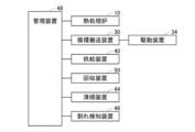
図面を参照して、本実施例に係る熱処理システム1について説明する。図1及び図2に示すように、熱処理システム1は、熱処理炉10と、循環搬送装置30と、供給装置40と、回収装置50と、清掃装置44と、割れ検知装置46と、管理装置48を備えている。
Example 1
A
熱処理システム1は、匣鉢2(図3参照)に収容された被処理物を熱処理する。本実施例では、匣鉢2に収容される被処理物は、リチウムイオン電池正極材の粉体である。本実施例の熱処理システム1では、匣鉢2は、供給装置40、熱処理炉10、回収装置50、清掃装置44及び割れ検知装置46の間を循環するように構成されている。被処理物は、匣鉢2が熱処理炉10内を搬送される間に熱処理される。図2に示すように、管理装置48は、熱処理炉10と、循環搬送装置30と、供給装置40と、回収装置50と、清掃装置44と、割れ検知装置46と接続している。管理装置48は、熱処理炉10と、循環搬送装置30と、供給装置40と、回収装置50と、清掃装置44と、割れ検知装置46の動作を制御している。
The
熱処理炉10は、匣鉢2内の被処理物を熱処理する。図3及び図4に示すように、熱処理炉10は、炉体12と、搬送装置(24、26)を備えている。熱処理炉10は、搬送装置(24、26)によって匣鉢2が炉体12内を搬送される間に、匣鉢2内に収容される被処理物を熱処理する。
The
炉体12は、外形が略直方体形状であり、その内部の熱処理空間が天井壁14aと、底壁14bと、炉入口壁14cと、炉出口壁14dと、側壁14e、14fによって囲まれている。図3に示すように、天井壁14aは、底壁14bに対して平行に(すなわち、XY平面と平行に)配置されている。炉入口壁14cは、搬送経路の入口端に配置されており、搬送方向に対して垂直に(すなわち、YZ平面と平行に)配置されている。炉出口壁14dは、搬送経路の出口端に配置されており、炉入口壁14cに対して平行に(すなわち、YZ平面と平行に)配置されている。図4に示すように、側壁14e、14fは、搬送方向に対して平行、かつ、天井壁14a及び底壁14bに対して垂直に(すなわち、XZ平面と平行に)配置されている。炉体12内の熱処理空間には、複数のヒータ16a、16bと、複数の搬送ローラ24が配置されている。ヒータ16aは、搬送ローラ24の上方の位置に搬送方向に所定の間隔で配置され、ヒータ16bは、搬送ローラ24の下方の位置に搬送方向に所定の間隔で配置されている。ヒータ16a、16bが発熱することで、炉体12内の空間18が加熱されると共に匣鉢2内に収容される被処理物が加熱される。図3に示すように、炉入口壁14cには、開口15aが形成されており、炉出口壁14dには、開口15bが形成されている。匣鉢2は、搬送装置(24、26)によって開口15aから熱処理炉10内に搬送され、開口15bから熱処理炉10外へ搬送される。すなわち、開口15aは搬入口として用いられ、開口15bは搬出口として用いられる。
The
搬送装置(24、26)は、複数の搬送ローラ24と、駆動装置26を備えている。搬送ローラ24は、匣鉢2を搬送する。搬送装置(24、26)は、開口15aから熱処理炉10内に匣鉢2を搬送し、開口15bから匣鉢2を熱処理炉10外に搬送する。搬送ローラ24は円筒状であり、その軸線は搬送方向と直交する方向に(すなわち、Y方向に)伸びている。複数の搬送ローラ24は、全てが同じ直径を有しており、搬送方向に一定のピッチで等間隔に配置されている。搬送ローラ24は、その軸線回りに回転可能に支持されており、駆動装置26の駆動力が伝達されることによって回転する。駆動装置26は、搬送ローラ24を駆動する駆動装置(例えば、モータ)である。駆動装置26は、動力伝達機構を介して、搬送ローラ24に接続されている。駆動装置26の駆動力が動力伝達機構(例えば、スプロケットとチェーンによる機構)を介して搬送ローラ24に伝達されると、搬送ローラ24は回転するようになっている。駆動装置26は、搬送ローラ24が略同一の速度で回転するように、搬送ローラ24のそれぞれを駆動する。駆動装置26は、制御装置28によって制御されている。なお、本実施例では、複数の搬送ローラ24は、全て同じ直径を有しているが、このような構成に限定されない。熱処理炉10内には、異なる直径の搬送ローラが設置されていてもよい。
The conveying device (24, 26) includes a plurality of conveying
図1に示すように、循環搬送装置30は、熱処理炉10の搬出口(すなわち、開口15b)から搬出された匣鉢2を、熱処理炉10の搬入口(すなわち、開口15a)まで搬送する。循環搬送装置30は、複数の搬送ローラ32(図5及び図6参照)と、駆動装置34(図2参照)を備えている。搬送ローラ32は円筒状であり、その軸線は搬送方向と直交する方向に伸びている。複数の搬送ローラ32は、全てが同じ直径を有しており、搬送方向に一定のピッチで等間隔に配置されている。搬送ローラ32は、その軸線回りに回転可能に支持されており、駆動装置34の駆動力が伝達されることによって回転する。駆動装置34は、搬送ローラ32を駆動する駆動装置(例えば、モータ)である。駆動装置34は、動力伝達機構を介して、搬送ローラ24に接続されている。駆動装置34の駆動力が動力伝達機構(例えば、スプロケットとチェーンによる機構)を介して搬送ローラ32に伝達されると、搬送ローラ32は回転するようになっている。駆動装置34は、搬送ローラ32が略同一の速度で回転するように、搬送ローラ32のそれぞれを駆動する。なお、本実施例では、複数の搬送ローラ32は、全て同じ直径を有しているが、このような構成に限定されない。循環搬送装置30の搬送経路には、異なる直径の搬送ローラが設置されていてもよい。
As shown in FIG. 1, the circulating conveying
図1に示すように、供給装置40は、循環搬送装置30の搬送経路上に配置されている。供給装置40は、熱処理炉10の搬入口の上流に配置されており、本実施例では、割れ検知装置46と熱処理炉10の搬入口との間に配置されている。供給装置40は、匣鉢2内に被処理物(すなわち、粉体)を供給する装置である。なお、供給装置40は、匣鉢2内に粉体を供給するように構成されていればよく、具体的な構造については特に限定されない。例えば、供給装置40は、供給部と均し部を備えている。供給部は、匣鉢2の内部に粉体を供給するように構成されている。具体的には、供給部は、匣鉢2の上方から匣鉢2の内部に粉体を落下させる供給口を備えている。供給口は、供給部内に匣鉢2を配置したときに、匣鉢2の中心部の上方に位置するように配置されている。供給部は、位置決め装置を備えており、位置決め装置は、供給部に搬送された匣鉢2を、供給口の下方に位置するように位置決めする。なお、供給部には、複数の供給口が配置されていてもよい。供給部は、粉体を上方から落下させることで匣鉢2内に粉体を供給するため、供給部で匣鉢2に粉体が供給されると、匣鉢2内の粉体の上面は、供給口の下方の位置で盛り上がった状態となる。均し部は、供給部で匣鉢2内に供給された粉体を均す。具体的には、均し部は、平板の側面で匣鉢2内の粉体の上面を押さえることで粉体の上面を均すように構成されている。均し部で粉体の上面を均すことによって、匣鉢2に収容された粉体の上面は略水平面となる。
As shown in FIG. 1, the
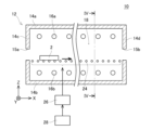
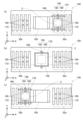
回収装置50は、循環搬送装置30の搬送経路上に配置されている。回収装置50は、熱処理炉10の搬出口の下流に配置されており、本実施例では、熱処理炉10と清掃装置44との間に配置されている。回収装置50は、熱処理炉10で熱処理された被処理物(すなわち、粉体)を匣鉢2から回収する装置である。回収装置50には、回収装置50の搬入口から搬出口まで搬送経路に沿って搬送ローラ32が設置されている(図5及び図6参照)。匣鉢2は、回収装置50内を搬送ローラ32によって搬送される。図5~図8に示すように、回収装置50は、シュート52と、貯留容器54と、フード56と、把持部58と、移動装置64と、ブラシ74と、吸引装置76を備えている。
The
シュート52は、匣鉢2内の被処理物を回収する。回収装置50に搬入される匣鉢2には、熱処理炉10で熱処理された被処理物が収容されている。シュート52には、熱処理後の被処理物が回収される。シュート52は、搬送ローラ32が配置されていない位置に配置されている。具体的には、シュート52は、搬送ローラ32が配置される位置(以下、単に「搬送経路」ともいう)に対して、匣鉢2の搬送方向(以下、単に「搬送方向」ともいう)に直交する方向(本実施例では、-Y方向)にオフセットした位置に配置されている。図5(a)及び図5(b)では、シュート52は、搬送経路である上側からオフセットした下側に配置されており、図6(a)及び図6(b)では、シュート52は、搬送経路である右側からオフセットした左側に配置されている。
The
図5及び図6に示すように、シュート52は、矩形の筒状あり、下方に向かって断面積が小さくされている。シュート52の上端は、匣鉢2を上面視したときの匣鉢2の外形より大きくされている(図5(a)及び図5(b)参照)。シュート52の下端には、貯留部54が接続されている(図6(a)及び図6(b)参照)。シュート52の上方で匣鉢2を反転すると、匣鉢2内に収容されていた被処理物がシュート52を通って貯留容器54に貯留される。
As shown in Figures 5 and 6, the
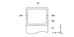
フード56は、シュート52の上面を覆うように設置されている。フード56の下端は、シュート52の上端と接続しており、シュート52とフード56との間は密閉されている。フード56の高さ方向の寸法は、匣鉢2の高さ方向の寸法より大きくされている。フード56には、匣鉢2を収容可能な大きさの空間が設けられている。
The
図7に示すように、フード56の搬送方向と平行な側面のうち、搬送経路側に位置する側面(+Y方向側の側面)には、開口部56a(以下、第1の開口部56aともいう)が設けられている。第1の開口部56aは、匣鉢2が通過可能な大きさを有しており、本実施例では、第1の開口部56aは、フード56の搬送経路側の側面全体と一致する大きさにされている。すなわち、フード56には、搬送経路側の側面が設けられていない。なお、第1の開口部56aは、匣鉢2が通過可能な大きさであればよく、フード56の側面の一部が開口していてもよい。
As shown in FIG. 7, among the sides of the
図6に示すように、フード56の搬送方向と直交する2つの側面(+X方向側と-X方向側の2つの側面)には、開口部56b(以下、第2の開口部56bともいう)が設けられている。第2の開口部56bは、フード56をX方向に沿って見たときに、フード56の略中央の高さ位置に設けられ、Y方向に沿って延びている。第2の開口部56bは、+Y方向側の端部は外部と連通しており、-Y方向側の端部は外部と連通していない。第2の開口部56bは、匣鉢2をフード56内に挿入するときに、把持部58(後述)が通過するように構成されている。
As shown in FIG. 6,
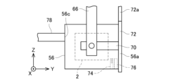
図5及び図6に示すように、把持部58は、匣鉢2の対向する一対の側面に当接して匣鉢2を把持する。把持部58は、一対の把持片60と、把持片60が先端に固定された回転軸62を備えている。把持片60は、匣鉢2の搬送方向に直交する側面に当接して、匣鉢2を把持する。すなわち、一対の把持片60は、図示しないアクチュエータによって開閉動作が可能となっている。一対の把持片60に閉動作を行わせると一対の支持片60に匣鉢2を把持し、一対の把持片60に開動作を行わせると一対の支持片60から匣鉢2を開放する。回転軸62は、円筒状であり、その軸線回りに回転可能に支持フレーム66(後述)に支持されている。回転軸62が回転すると、把持片60が回転軸62と一体的に回転する。把持片60で匣鉢2を把持した状態で回転軸62を回転させると、把持片60に把持された匣鉢2も回転(反転)する。
5 and 6, the gripping
移動装置64は、匣鉢2を、回収装置50内で搬送ローラ32上に載置されている位置(図6(a)に示す位置であり、以下、載置位置ともいう)と、シュート52の上方の位置(図5(b)及び図6(c)に示す位置であり、以下、回収位置ともいう)との間で移動させる。移動装置64は、載置位置に位置する匣鉢2を昇降させる昇降ピン65と、回転軸62を回転可能に支持する支持フレーム66と、移動ベース68aと、ガイドレール68を備えている。
The moving
昇降ピン65は、載置位置に位置する匣鉢2の下方に配置されている。図5(a)及び図5(b)に示すように、昇降ピン65は、搬送ローラ32の間に配置されている。昇降ピン65は、上下方向に移動可能に構成されている。昇降ピン65が上昇すると、搬送ローラ32の間を通過して、昇降ピン65の上端は、載置位置に位置する匣鉢2の下面に当接する。本実施例では、昇降ピン65は4本配置されており、4本の昇降ピン65で匣鉢2を下方から支持する。昇降ピン65が昇降することで、匣鉢2を上下方向に移動させる。支持フレーム66は、移動ベース68aに固定されている。移動ベース68aがガイドレール68に沿って移動することにより、支持フレーム66は、ガイドレール68に沿って移動する。ガイドレール68は、載置位置及び回収位置の上方において、搬送方向と直交する方向(Y方向)に伸びている。支持フレーム66は、把持部58をガイドレール68に沿ってY方向に移動させる。すなわち、把持部58で匣鉢2を把持した状態では、支持フレーム66が把持部58を移動させることによって、匣鉢2がY方向に移動する。
The lifting pins 65 are arranged below the
ここで、匣鉢2が搬送経路上の載置位置と、シュート52の上方の回収位置との間で移動する動作について説明する。匣鉢2は、搬送ローラ32によって回収装置50内に搬送される。匣鉢2が回収装置50内の載置位置まで搬送されると、昇降ピン65が上昇する(図6(a)の状態)。すると、昇降ピン65の上端が匣鉢2の下面に当接し、匣鉢2が上昇する。これにより、匣鉢2は、搬送ローラ32から離れ、搬送ローラ32の上方に移動する。次いで、一対の把持片60が互いに近接する方向に移動して匣鉢2の側面に当接する。これによって、一対の把持片60によって匣鉢2が把持される(図5(a)及び図6の(b)の状態)。匣鉢2が把持部58に把持されると、昇降ピン65が下降する。すると、昇降ピン65は、把持部58に把持された匣鉢2から離れる。次いで、支持フレーム66によって把持部58が側方(本実施例では、-Y方向)に移動され、匣鉢2は、第1の開口部56aからフード56内に収容される(図5(b)及び図6(c)の状態)。このとき、図5(b)に示すように、匣鉢2と共に、匣鉢2を把持している把持片60はフード56に収容される。把持片60が先端に固定された回転軸62は、把持片60側の端部がフード56内に収容され、反対側の端部が第2の開口部56bから突出してフード56外に位置する。すなわち、匣鉢2を第1の開口部56aからフード56内に挿入するときには、回転軸62は、第2の開口部56bを通過した状態で、第2の開口部56bに沿って側方に移動する。これにより、匣鉢2を把持部58で把持したまま、匣鉢2をフード56内に収容することができる。
Here, the movement of the
匣鉢2がフード56内に収容されると、回転軸62を軸周りに180度回転させる。すると、回転軸62と共に、把持片60及び把持片60で把持された匣鉢2が180度回転し、匣鉢2が下方に開口した状態となる。フード56の下方には、シュート52が配置されている。フード56内で匣鉢2を反転させることによって、匣鉢2内に収容された被処理物がシュート52に回収される。次いで、回転軸62を軸線回りにさらに180度回転させる。すると、回転軸62と共に匣鉢2が180度回転し、匣鉢2が上方に開口した状態となる。このとき、回転軸62は、匣鉢2を反転させたときと反対方向に回転する。なお、回転軸62は、匣鉢2を反転させたときと同一方向に回転してもよい。次いで、支持フレーム66によって把持部58が+Y方向に移動され、匣鉢2は、第1の開口部56aからフード56外に取り出される。匣鉢2が載置位置の上方まで移動すると、昇降ピン65の上端が匣鉢2の下面に当接するまで、昇降ピン65が上昇する。次いで、一対の把持片60が互いに離間する方向に移動する。これにより、匣鉢2が把持部58に把持された状態が解除され、匣鉢2は、昇降ピン65に支持された状態となる。次いで、昇降ピン65が下降し、匣鉢2は再び搬送ローラ32上の載置位置に戻される。その後、匣鉢2は、搬送ローラ32によって回収装置50外に搬送される。
When the
また、移動装置64には、搬送方向に直交して配置されるカバー70(以下、第1カバー70ともいう)と、搬送方向に平行に配置されるカバー72(以下、第2カバー72ともいう)が取り付けられている。
The moving
第1カバー70は、支持フレーム66に取り付けられている。第1カバー70は、矩形の板状であり、第2の開口部56bより大きくされている。第1カバー70は、匣鉢2をフード56内に収容したときに、フード56の外側で第2の開口部56bに沿って位置するように配置されている。第1カバー70は、匣鉢2をフード56内に収容したときに、第2の開口部56bを覆う。なお、第1カバー70は、匣鉢2をフード56内に収容した後、第2の開口部56bに向かって押し付けられるように移動可能に構成されていてもよい。第1カバー70を設けることによって、匣鉢2をフード56内に収容したときに、第2の開口部56bが第1カバー70によって塞がれる。このため、フード56内で匣鉢2を反転させたときに、第2の開口部56bから被処理物がフード56外に飛散することを抑制することができる。
The
第2カバー72は、把持部58に対してフード56の反対側に配置されている。第2カバー72は、矩形の板状であり、第1の開口部56aより大きくされている。第2カバー72は、連結フレーム72aの下端に固定されている。連結フレーム72aの上端は、移動ベース68aに固定されている。すなわち、移動ベース68aを移動させると、第2カバー72は、把持部58と共に移動する。第2カバー72は、匣鉢2をフード56内に収容したときに、第1の開口部56aを覆う位置に配置されている。第2カバー72を設けることによって、匣鉢2をフード56内に収容したときに、第1の開口部56aが第2カバー72によって塞がれる。このため、フード56内で匣鉢2を反転させたときに、第1の開口部56aから被処理物がフード56外に飛散することを抑制することができる。
The
図8に示すように、ブラシ74及び吸引装置76は、フード56内に配置されている。具体的には、ブラシ74及び吸引装置76は、第1の開口部56aの近傍に配置されている。ブラシ74及び吸引装置76は、X方向に沿って延びている。ブラシ74は、匣鉢2がフード56から取り出されるときに、匣鉢2の底面に接触するように配置されている。ブラシ74は、匣鉢2がフード56から取り出されるときに、匣鉢2の外表面(特に、底面)に付着した被処理物を匣鉢2の外表面から剥離する。吸引装置76は、ブラシ74の近傍に配置されている。吸引装置76は、ブラシ74で匣鉢2から剥離した被処理物を吸引する。フード56内で匣鉢2を反転させると、フード56内で被処理物(すなわち、粉体)が舞い上がる。フード56内で粉体が舞い上がると、匣鉢2の外表面に粉体が付着することがある。ブラシ74及び吸引装置76で匣鉢2の外表面に付着した被処理物(すなわち、粉体)を除去することによって、匣鉢2がフード56外に取り出されたときに、匣鉢2の外表面に付着する被処理物が減少する。これにより、匣鉢2が回収位置から搬送ローラ32上の載置位置に戻されたときに、搬送ローラ32に被処理物が付着することを抑制することができる。
As shown in FIG. 8, the
また、フード56には、集塵ダクト78が接続されている。具体的には、フード56には、第1の開口部56aと対向する側面(-Y方向側の側面)に第3の開口部56cが設けられている。第3の開口部56cは、集塵ダクト78の内径以下の大きさにされている。集塵ダクト78は、一端が第3の開口部56cと連通しており、他端が吸引装置(図示省略)に接続されている。これにより、集塵ダクト78を介してフード56内の空気が吸引され、フード56内の空間は微負圧状態となる。フード56内で匣鉢2を反転させると、フード56内で被処理物(すなわち、粉体)が舞い上がる。フード56内の空間を微負圧状態にすることにより、被処理物がフード56外に飛散することを抑制することができる。
The
本実施例の回収装置50では、搬送経路からオフセットした位置にシュート52を配置し、匣鉢2をシュート52の上方に移動させている。これにより、匣鉢2を搬送ローラ32と共に反転する必要がなくなり、匣鉢2のみを反転させることができる。このため、匣鉢2の反転速度を大きくすることが可能となり、結果として被処理物を回収するために要する時間を短くすることができる。
In the
また、本実施例では、匣鉢2を搬送ローラ32からオフセットした位置で反転させるため、搬送ローラ32上に被処理物が飛散することを抑制できる。搬送ローラ32上で被処理物が飛散すると、搬送ローラ32や、搬送ローラ32を駆動するための機構(例えば、スプロケットやチェーン等)に被処理物が付着する。搬送ローラ32や搬送ローラ32を駆動するための機構に被処理物が堆積すると、匣鉢2の外表面に堆積した被処理物が付着し、匣鉢2の外表面に付着した被処理物がシュート52内に侵入することにより、コンタミの原因になることがある。本実施例では、搬送経路上で飛散する被処理物の量を低減できるため、コンタミのリスクを低減することができる。また、搬送ローラ32に被処理物が付着し難くなり、匣鉢2の外表面(底面)と搬送ローラ32との間の被処理物の転写により回収装置50内が被処理物で汚損されることを抑制することができる。
In addition, in this embodiment, the
また、搬送ローラ32と共に匣鉢2を反転させると、これらを反転させるための機構が複雑になり、シュート52の上方に搬送ローラ32を含む多くの部品等が配置されることになる。シュート52の上方に多くの部品等が配置されることにより、シュート52に部品等が混入する可能性が生じ、シュート52に被処理物以外の物質(部品等)が混入するリスクが生じる。本実施例では、シュート52の上方で匣鉢2のみを反転させるため、シュート52に被処理物以外の異物が混入し難くなる。また、匣鉢2を反転させる機構が複雑化することを回避できるため、反転機構が故障し難くなる。さらに、シュート52(すなわち、匣鉢2を反転する位置)が搬送経路からオフセットした位置に配置されているため、シュート52や反転機構をメンテナンスする際に、搬送ローラ32を移動させる必要がない。このため、搬送ローラ32と共に匣鉢2を反転させる構成と比較して、シュート52や反転機構のメンテナンスを容易にすることができる。
In addition, if the
また、本実施例では、載置位置と回収位置が異なるため、匣鉢2は回収位置とは異なる位置で把持された状態となる。例えば、匣鉢2にヒビ等の破損がある場合、匣鉢2を把持するために把持部58で匣鉢2を押圧したときに匣鉢2が割れる虞がある。匣鉢2を把持することによって匣鉢2が割れたとしても、回収位置とは異なる位置で匣鉢2が割れるため、シュート52内に匣鉢2の破片等が混入することを回避することができる。
In addition, in this embodiment, since the placement position and the recovery position are different, the
清掃装置44は、回収装置50において粉体が回収された後の匣鉢2の内表面を清掃する装置である。なお、清掃装置44は、匣鉢2の内表面を清掃するように構成されていればよく、具体的な構造については特に限定されない。例えば、清掃装置44は、回転ブラシを用いて匣鉢2の内表面に付着している物質を剥離させながら、匣鉢2内の空気等を吸引する。吸引した空気等には、剥離された物質が含まれる。清掃装置44で匣鉢2の内表面を清掃することにより、匣鉢2の内表面に残留した粉体を完全に除去することができる。
The
割れ検知装置46は、匣鉢2の割れを検知することによって、匣鉢2が割れていないか否かを検査するための装置である。匣鉢2は、熱処理炉10において被処理物の熱処理に繰り返し使用される。割れ検知装置46は、匣鉢2が熱処理炉10において被処理物の熱処理に使用された後、再使用する前に割れていないか否かを検査する。なお、割れ検知装置46は、匣鉢2の割れを検知するように構成されていればよく、具体的な構成については特に限定されない。例えば、割れ検知装置46は、レーザを用いて匣鉢2の割れを検出してもよい。また、割れ検知装置46は、匣鉢2にガスを封入し、匣鉢2内の圧力を測定することによって匣鉢2の割れを検出してもよい。匣鉢2の割れが検知された場合、匣鉢2は循環搬送装置30の搬送経路から取り出される。匣鉢2の割れが検知されなかった場合、匣鉢2は、循環搬送装置30によって供給装置40に搬送される。
The
なお、本実施例では、循環搬送装置30は、搬送ローラ32によって匣鉢2を搬送するローラコンベアであったが、このような構成に限定されない。匣鉢2を熱処理炉10の搬出口から搬出された匣鉢2を、熱処理炉10の搬入口まで搬送するように構成されていればよく、例えば、循環搬送装置は、ベルトによって匣鉢2を搬送するベルトコンベアであってもよい。また、本実施例では、載置位置と回収位置との間で匣鉢2を移動させる際に、昇降ピン65で匣鉢2を昇降させていたが、このような構成に限定されない。載置位置において、搬送ローラ32とその上方の位置との間で匣鉢2を昇降できればよく、例えば、エレベータを設置して匣鉢2を昇降させてもよい。
In this embodiment, the circulating
また、本実施例では、回収装置50が備えるシュート52は、搬送経路から上下方向及び側方(Y方向)にオフセットした位置に配置されていたが、このような構成に限定されない。シュート52は、搬送経路からオフセットした位置に配置されていればよく、例えば、シュート52は、搬送経路の側方のみにオフセットしていてもよいし、上方のみにオフセットしていてもよい。これらの場合にも、匣鉢2を搬送ローラ32と共に反転する必要がなく、匣鉢2のみを反転させることができる。
In addition, in this embodiment, the
(実施例2)
上記の実施例では、回収装置50のシュート52は、搬送経路からオフセットした位置に配置されていたが、このような構成に限定されない。搬送ローラ32が配置されていない位置で匣鉢2を反転できればよく、例えば、図9及び図10に示すように、回収装置150のシュート152は、搬送ローラ32が配置されていない搬送経路上の位置に配置されていてもよい。
Example 2
In the above embodiment, the
回収装置150は、シュート152と、フード156と、把持部158と、移動装置164と、第1カバー170と、第2カバー172を備えている。なお、本実施例においても、回収装置150は、ブラシ74と吸引装置76(図示省略)を備えているが、上記の実施例1と略同一の構成であるため、詳細な説明は省略する。
The
回収装置150では、搬送経路上に、回収装置150の搬入口側(+X方向側)に配置される複数の搬送ローラ32a(以下、搬入側搬送ローラ32aともいう)と、回収装置150の搬出口側(-X方向側)に配置される複数の搬送ローラ32b(以下、搬出側搬送ローラ32bともいう)が配置されている。搬入側搬送ローラ32aと搬出側搬送ローラ32bとの間には、搬送ローラ32、32a、32bが配置されていない領域が設けられている。シュート152は、搬入側搬送ローラ32aと搬出側搬送ローラ32bとの間の搬送ローラ32、32a、32bが配置されていない領域に配置されている。シュート152の上端には、フード156が接続されており、シュート152の下端には、貯留容器154が接続されている。
In the
フード156は、シュート152の上面を覆うように設置されている。フード156には、匣鉢2を収容可能な大きさの空間が設けられている。フード156の搬送方向と直交する2つの側面(+X方向側と-X方向側の2つの側面)には、開口部156a(以下、第1の開口部156aともいう)が設けられている。図11に示すように、第1の開口部156aは、匣鉢2が通過可能な大きさを有しており、本実施例では、フード156の側面の上部と下部は開口しておらず、フード156の側面のうち中央部分のみが開口している。なお、第1の開口部156aは、匣鉢2が通過可能な大きさであればよく、フード156の搬送方向と直交する側面全体と一致する大きさにされていてもよい。
The
図10に示すように、フード156の搬送方向と平行な2つの側面(+Y方向側と-Y方向側の2つの側面)には、スリット156b(第2の開口部の一例)が設けられている。スリット156bは、フード156をY方向に沿って見たときに、フード156の略中央の高さ位置に設けられている。スリット156bは、フード156の側面全体においてX方向に沿って延びており、スリット156bの+Y方向側の端部も-Y方向側の端部も外部と連通している。このため、フード156は、第1の開口部156aとスリット156bによって、上フードと下フードに分割されている。スリット156bは、匣鉢2をフード156内に挿入するときに、把持部158が通過するように構成されている。
As shown in FIG. 10,
図9及び図10に示すように、把持部158は、匣鉢2の搬送方向と平行な側面に当接して匣鉢2を把持する。把持部158は、一対の把持片160と、把持片160が固定された回転軸162を備えている。なお、把持部158は、匣鉢2の搬送方向と平行な側面を把持する点が、上記の実施例1の構成と相違しており、その他の構成は略同一である。このため、把持部158の詳細な説明は省略する。
As shown in Figures 9 and 10, the gripping
移動装置164は、匣鉢2を、搬入側搬送ローラ32a上に載置されている位置(図9(a)に示す位置)と、シュート152の上方の位置(図9(b)及び図10(b)に示す位置)と、搬出側搬送ローラ32b上に載置されている位置(図9(c)に示す位置)との間で移動させる。すなわち、本実施例では、移動装置164は、匣鉢2を搬送経路に沿って移動させる。
The moving
移動装置164は、匣鉢2を昇降させる昇降ピン165と、回転軸162を回転可能に支持する支持フレーム166と、ガイドレール168を備えている。昇降ピン165は、シュート152の近傍に配置される搬入側搬送ローラ32a間に配置されていると共に、シュート152の近傍に配置される搬出側搬送ローラ32b間に配置されている。昇降ピン165は、上下方向に移動可能に構成されている。昇降ピン165が上昇すると、搬入側搬送ローラ32a又は搬出側搬送ローラ32bの間を通過して、昇降ピン165の上端は、昇降ピン165の上方に位置する匣鉢2の下面に当接する。本実施例では、昇降ピン165は4本配置されており、昇降ピン65が昇降することで、匣鉢2を上下方向に移動させる。支持フレーム166は、移動ベース168aに固定されている。移動ベース168aがガイドレール168に案内されて移動することにより、支持フレーム166は、ガイドレール168に沿って移動する。ガイドレール168は、搬送経路上において、搬送経路に沿って(すなわち、X方向)に伸びている。支持フレーム166は、把持部158をガイドレール168に沿ってX方向に移動させる。すなわち、把持部158で匣鉢2を把持した状態では、支持フレーム166が把持部158を移動させることによって、匣鉢2がX方向に移動する。
The moving
第1カバー170は、スリット156bを塞ぐためのカバーである。第1カバー170は、支持フレーム166に取り付けられている。第1カバー170は、矩形の板状であり、スリット156bより大きくされている。第1カバー170は、匣鉢2をフード156内に収容したときに、フード156の外側でスリット156bに沿って位置するように配置されている。第1カバー170は、匣鉢2をフード156内に収容したときに、スリット156bを覆う。なお、第1カバー170は、匣鉢2をフード156内に収容した後、スリット156bに向かって押し付けられるように移動可能に構成されていてもよい。
The
第2カバー172は、第1の開口部156aを塞ぐためのカバーである。第2カバー172は、フード156の搬送方向に直交する側面に取り付けられている。第2カバー172は、矩形の板状であり、第1の開口部156aより大きくされている。第2カバー172は、開閉可能に構成されており、閉じた状態で第1の開口部156aを覆うように配置されている。第2カバー172は、上端がフード156の側面に取り付けられている。第2カバー172は、駆動装置(図示省略)によって、第1の開口部156aを覆う位置と、フード156の側面に対して直交する位置との間で移動可能(すなわち、開閉可能)となっている。
The
匣鉢2が回収装置150内を搬送される動作について説明する。本実施例では、移動装置164は、匣鉢2を搬送経路に沿って移動させる。匣鉢2は、搬入側搬送ローラ32aによって搬送され、シュート152が配置される位置の近傍まで搬送されると、昇降ピン165が上昇する。すると、昇降ピン165の上端が匣鉢2の下面に当接して匣鉢2が上昇し、匣鉢2は、搬入側搬送ローラ32aから持ち上げられる。次いで、匣鉢2は、把持部158によって把持される(図9(a)及び図10(a)の状態)。匣鉢2が把持部158に把持されると、昇降ピン165は、下降して匣鉢2から離れる。このとき、第2カバー172は、は開いた状態となっている。
The operation of conveying the
次いで、支持フレーム166によって把持部158が搬送経路に沿って(本実施例では、-X方向)に移動され、匣鉢2は、搬入側搬送ローラ32a側(+X方向側)の第1の開口部156aからフード56内に収容される。匣鉢2がフード156内に収容されると、第2カバー172が閉じられる(図9(b)及び図10(b)の状態)。このとき、図9(b)に示すように、匣鉢2と共に、匣鉢2を把持している把持片160はフード156に収容される。把持片160が固定された回転軸162は、把持片160側の端部がフード156内に収容され、反対側の端部がスリット156bから突出してフード156外に位置する。次いで、回転軸162を軸周りに180度回転させ、匣鉢2を反転させる。これにより、匣鉢2内に収容された被処理物がシュート152に回収される。匣鉢2は、第2カバー172を閉じた状態で反転される。このため、第1の開口部56aから被処理物がフード56外に飛散することを抑制することができる。また、匣鉢2をフード156内に収容すると、第1カバー170によってスリット156bが覆われる。このため、スリット156bから被処理物がフード156外に飛散することを抑制することができる。
Next, the gripping
次いで、回転軸62を軸線回りにさらに180度回転させ、匣鉢2を元の状態(上方に開口した状態)に戻す。次いで、第2カバー172が開けられる。そして、支持フレーム166によって把持部158が搬送経路に沿って(本実施例では、-X方向)に移動される。これにより、匣鉢2は、搬出側搬送ローラ32b側(-X方向側)の第1の開口部156aからフード56外に取り出される。匣鉢2が搬出側搬送ローラ32b上まで移動すると、昇降ピン165の上端が匣鉢2の下面に当接するまで、昇降ピン165が上昇する。次いで、一対の把持片60が互いに離間する方向に移動して、匣鉢2が把持部158に把持された状態が解除される。次いで、昇降ピン165が下降し、搬出側搬送ローラ32b上に載置される(図9(c)及び図10(c)の状態)。その後、匣鉢2は、搬出側搬送ローラ32bによって回収装置50外に搬送される。
Next, the rotating
本実施例においても、シュート152は、搬送ローラ32、32a、32bが配置されていない位置に配置されている。これにより、匣鉢2を搬送ローラ32と共に反転する必要がなくなり、匣鉢2のみを反転させることができる。
In this embodiment, the
実施例で説明した熱処理システム1に関する留意点を述べる。実施例の循環搬送装置30は、「搬送装置」の一例であり、搬送ローラ32は、「搬送機構」の一例であり、シュート52は及び貯留容器54は、「回収部」の一例であり、回転軸62は、「支持部」の一例である。
Notes regarding the
以上、本明細書に開示の技術の具体例を詳細に説明したが、これらは例示にすぎず、特許請求の範囲を限定するものではない。特許請求の範囲に記載の技術には、以上に例示した具体例を様々に変形、変更したものが含まれる。また、本明細書または図面に説明した技術要素は、単独であるいは各種の組合せによって技術的有用性を発揮するものであり、出願時請求項記載の組合せに限定されるものではない。また、本明細書または図面に例示した技術は複数目的を同時に達成するものであり、そのうちの一つの目的を達成すること自体で技術的有用性を持つものである。 Specific examples of the technology disclosed in this specification have been described in detail above, but these are merely examples and do not limit the scope of the claims. The technology described in the claims includes various modifications and variations of the specific examples exemplified above. Furthermore, the technical elements described in this specification or drawings exert technical utility alone or in various combinations, and are not limited to the combinations described in the claims at the time of filing. Furthermore, the technology exemplified in this specification or drawings achieves multiple objectives simultaneously, and achieving one of those objectives is itself technically useful.
1:熱処理システム
2:匣鉢
10:熱処理炉
30:循環搬送装置
32、32a、32b:搬送ローラ
34:駆動装置
40:供給装置
44:清掃装置
46:割れ検知装置
50、150:回収装置
52、152:シュート
56、156:フード
56a、156a:第1の開口部
56b、156b:第2の開口部
58、158:把持部
60、160:把持片
62、162:回転軸
64、164:移動装置
66、166:支持フレーム
68、168:ガイドレール
70、170:第1カバー
72、172:第2カバー
74:ブラシ
76:吸引装置
78:集塵ダクト
1: Heat treatment system 2: Sagger 10: Heat treatment furnace 30:
Claims (11)
前記熱処理炉の前記搬出口から搬出された前記匣鉢を前記熱処理炉の前記搬入口まで搬送する搬送装置と、
前記搬送装置の搬送経路上に設けられ、前記熱処理炉で熱処理された前記被処理物を前記匣鉢から回収する回収装置と、
前記搬送装置の前記搬送経路上であって、前記回収装置と前記搬入口との間に設けられ、前記被処理物が収容されていない前記匣鉢に、熱処理前の前記被処理物を供給する供給装置と、を備えており、
前記搬送装置は、前記搬送経路に沿って配置された搬送機構と、前記搬送機構を駆動する駆動装置と、を備え、前記駆動装置が前記搬送機構を駆動することで前記搬送機構上に載置された前記匣鉢を搬送するように構成されており、
前記回収装置は、
前記搬送機構が配置されていない位置に設けられ、前記匣鉢内の前記被処理物を回収する回収部と、
前記搬送機構上の載置位置と前記回収部の上方の回収位置との間で前記匣鉢を移動させる移動装置と、
前記回収位置において前記匣鉢を反転させる反転機構と、
前記回収部を上方から覆い、前記匣鉢を収容可能に構成されるフードと、を備えており、
前記フードは、前記匣鉢を前記フード内に収容するための開口部を備えており、
前記回収装置は、前記開口部を開閉するカバーをさらに備えており、
前記カバーは、前記移動装置によって前記匣鉢が前記フード内に収容されるときに前記匣鉢と共に移動し、前記匣鉢が前記フード内に収容されたときに前記開口部を塞ぐように構成されている、熱処理システム。 a heat treatment furnace having an inlet and an outlet, for heat-treating the workpiece contained in the sagger while transporting the sagger from the inlet to the outlet;
a conveying device that conveys the sagger discharged from the discharge outlet of the heat treatment furnace to the discharge inlet of the heat treatment furnace;
a recovery device that is provided on a transport path of the transport device and recovers the workpiece that has been heat-treated in the heat treatment furnace from the sagger;
a supply device that is provided on the transport path of the transport device between the recovery device and the entrance and that supplies the workpiece before heat treatment to the sagger in which the workpiece is not contained,
the conveying device includes a conveying mechanism disposed along the conveying path, and a driving device that drives the conveying mechanism, and is configured to convey the sagger placed on the conveying mechanism by driving the conveying mechanism with the driving device;
The recovery device includes:
a recovery unit that is provided at a position where the transport mechanism is not disposed and that recovers the object to be processed in the sagger;
a moving device that moves the sagger between a placement position on the transport mechanism and a collection position above the collection section;
an inversion mechanism for inverting the sagger at the recovery position;
A hood configured to cover the collection section from above and accommodate the sagger ,
the hood includes an opening for receiving the sagger within the hood;
The recovery device further includes a cover that opens and closes the opening,
A heat treatment system, wherein the cover is configured to move with the sagger when the sagger is housed within the hood by the moving device and to close the opening when the sagger is housed within the hood .
前記熱処理炉の前記搬出口から搬出された前記匣鉢を前記熱処理炉の前記搬入口まで搬送する搬送装置と、a conveying device that conveys the sagger discharged from the discharge outlet of the heat treatment furnace to the discharge inlet of the heat treatment furnace;
前記搬送装置の搬送経路上に設けられ、前記熱処理炉で熱処理された前記被処理物を前記匣鉢から回収する回収装置と、a recovery device that is provided on a transport path of the transport device and recovers the workpiece that has been heat-treated in the heat treatment furnace from the sagger;
前記搬送装置の前記搬送経路上であって、前記回収装置と前記搬入口との間に設けられ、前記被処理物が収容されていない前記匣鉢に、熱処理前の前記被処理物を供給する供給装置と、を備えており、a supply device that is provided on the transport path of the transport device between the recovery device and the entrance and that supplies the workpiece before heat treatment to the sagger in which the workpiece is not contained,
前記搬送装置は、前記搬送経路に沿って配置された搬送機構と、前記搬送機構を駆動する駆動装置と、を備え、前記駆動装置が前記搬送機構を駆動することで前記搬送機構上に載置された前記匣鉢を搬送するように構成されており、the conveying device includes a conveying mechanism disposed along the conveying path, and a driving device that drives the conveying mechanism, and is configured to convey the sagger placed on the conveying mechanism by driving the conveying mechanism with the driving device;
前記回収装置は、The recovery device includes:
前記搬送機構が配置されていない位置に設けられ、前記匣鉢内の前記被処理物を回収する回収部と、a recovery unit that is provided at a position where the transport mechanism is not disposed and that recovers the object to be processed in the sagger;
前記搬送機構上の載置位置と前記回収部の上方の回収位置との間で前記匣鉢を移動させる移動装置と、a moving device that moves the sagger between a placement position on the transport mechanism and a collection position above the collection section;
前記回収位置において前記匣鉢を反転させる反転機構と、を備えており、and an inversion mechanism for inverting the sagger at the collection position,
前記搬送機構は、前記回収装置内の搬入側に配置される第1搬送機構と、前記回収装置内の搬出側に配置される第2搬送機構を含んでおり、the transport mechanism includes a first transport mechanism disposed on an input side of the recovery device and a second transport mechanism disposed on an output side of the recovery device;
前記回収部は、前記第1搬送機構と前記第2搬送機構との間に配置されている、熱処理システム。The recovery unit is disposed between the first transport mechanism and the second transport mechanism.
前記移動装置は、前記把持部で前記匣鉢を把持した前記反転機構を前記搬送機構上の載置位置と前記回収部の上方の回収位置との間で移動させるように構成されている、請求項1又は2に記載の熱処理システム。 the inversion mechanism includes a gripping portion that grips the sagger, and is configured such that the sagger gripped by the gripping portion is inverted by rotating the gripping portion around a rotation axis;
The heat treatment system of claim 1 or 2, wherein the moving device is configured to move the inversion mechanism, with the sagger gripped by the gripping section, between a loading position on the transport mechanism and a recovery position above the recovery section.
前記フードは、前記匣鉢及び前記把持部を収容可能に構成されており、
前記匣鉢を把持した前記把持部が、前記フードに収容された状態で前記回転軸周りに回転可能となっている、請求項3に記載の熱処理システム。 The recovery device further includes a hood that covers the recovery section from above,
The hood is configured to be able to accommodate the sagger and the grip portion,
The heat treatment system according to claim 3 , wherein the gripping portion that grips the sagger is rotatable about the rotation axis while being housed in the hood.
前記把持部は、前記匣鉢の対向する一対の側面に当接して前記匣鉢を把持する一対の把持片を備えており、
前記反転機構は、前記一対の把持片を支持する一対の支持部をさらに備えており、
前記一対の支持部のそれぞれは、前記匣鉢及び前記把持部が前記フード内に収容されたときに、その一端が前記フード内に位置する一方でその他端が前記フード外に位置するように構成されており、
前記開口部は、
第1の側面に設けられる第1の開口部と、
前記第1の側面と直交する第2の側面に設けられる第2の開口部と、を備えており、
前記第1の開口部は、前記第1の側面から前記匣鉢を前記フード内に挿入可能に構成されており、
前記第2の開口部は、前記匣鉢を前記フード内に収容したときに、前記支持部の他端が前記第2の開口部から前記フード外に突出するように構成されていると共に、前記匣鉢の挿入方向に沿って延びている、請求項4に記載の熱処理システム。 the hood includes an opening for receiving the sagger within the hood;
The gripping portion includes a pair of gripping pieces that abut against a pair of opposing side surfaces of the sagger to grip the sagger,
The inversion mechanism further includes a pair of support portions supporting the pair of gripping pieces,
each of the pair of support portions is configured such that, when the sagger and the grip portion are housed in the hood, one end of the support portion is located within the hood and the other end of the support portion is located outside the hood;
The opening is
A first opening provided on the first side surface;
a second opening provided on a second side surface perpendicular to the first side surface,
the first opening is configured to allow the sagger to be inserted into the hood from the first side surface,
The heat treatment system of claim 4, wherein the second opening is configured so that the other end of the support portion protrudes from the second opening to the outside of the hood when the sagger is housed in the hood , and extends along an insertion direction of the sagger.
前記カバーは、前記把持部に把持された前記匣鉢を前記フード内に収容したときに、前記第2の開口部を覆う第1のカバーを備えている、請求項5に記載の熱処理システム。 The recovery device further includes a cover that opens and closes the opening,
The heat treatment system according to claim 5 , wherein the cover comprises a first cover that covers the second opening when the sagger held by the holding portion is housed within the hood.
前記第2のカバーが前記第1の開口部を開いた状態では前記匣鉢が前記第1の開口部を通過可能とされ、前記第2のカバーが前記第1の開口部を閉じた状態では前記匣鉢が前記第1の開口部を通過不能とする、請求項6に記載の熱処理システム。 The cover further includes a second cover that opens and closes the first opening,
7. The heat treatment system of claim 6, wherein when the second cover opens the first opening, the sagger is able to pass through the first opening, and when the second cover closes the first opening, the sagger is unable to pass through the first opening.
前記搬送機構は、前記回収装置の前記搬入口から前記回収装置の前記搬出口まで前記搬送経路に沿って配置されており、
前記回収部は、前記搬送経路からオフセットした位置に配置されている、請求項1に記載の熱処理システム。 An inlet and an outlet of the recovery device are disposed on the transport path,
the transport mechanism is disposed along the transport path from the inlet of the recovery device to the outlet of the recovery device,
The heat treatment system according to claim 1 , wherein the recovery section is disposed at a position offset from the transport path.
The heat treatment system according to claim 4 , wherein the recovery device further comprises a suction device that sucks gas from within the hood.
Priority Applications (4)
| Application Number | Priority Date | Filing Date | Title |
|---|---|---|---|
| JP2022143096A JP7610552B2 (en) | 2022-09-08 | 2022-09-08 | Heat Treatment System |
| CN202311105938.5A CN117663747A (en) | 2022-09-08 | 2023-08-30 | Heat treatment system |
| US18/460,744 US20240085112A1 (en) | 2022-09-08 | 2023-09-05 | Heat treatment system |
| DE102023124037.4A DE102023124037A1 (en) | 2022-09-08 | 2023-09-06 | Heat treatment plant |
Applications Claiming Priority (1)
| Application Number | Priority Date | Filing Date | Title |
|---|---|---|---|
| JP2022143096A JP7610552B2 (en) | 2022-09-08 | 2022-09-08 | Heat Treatment System |
Publications (2)
| Publication Number | Publication Date |
|---|---|
| JP2024038803A JP2024038803A (en) | 2024-03-21 |
| JP7610552B2 true JP7610552B2 (en) | 2025-01-08 |
Family
ID=90054510
Family Applications (1)
| Application Number | Title | Priority Date | Filing Date |
|---|---|---|---|
| JP2022143096A Active JP7610552B2 (en) | 2022-09-08 | 2022-09-08 | Heat Treatment System |
Country Status (4)
| Country | Link |
|---|---|
| US (1) | US20240085112A1 (en) |
| JP (1) | JP7610552B2 (en) |
| CN (1) | CN117663747A (en) |
| DE (1) | DE102023124037A1 (en) |
Citations (2)
| Publication number | Priority date | Publication date | Assignee | Title |
|---|---|---|---|---|
| JP2020085367A (en) | 2018-11-27 | 2020-06-04 | 株式会社ノリタケカンパニーリミテド | Powder container reversing device for heating furnace |
| CN215063648U (en) | 2021-04-21 | 2021-12-07 | 广西七色珠光材料股份有限公司 | Automatic discharging system for roller kiln saggar |
Family Cites Families (4)
| Publication number | Priority date | Publication date | Assignee | Title |
|---|---|---|---|---|
| JP3330986B2 (en) * | 1992-11-17 | 2002-10-07 | 住友化学工業株式会社 | Powder filling and recovery equipment |
| KR950009997Y1 (en) * | 1993-12-29 | 1995-11-25 | 포항종합제절주식회사 | Ventilation Improvement Device of Sintering Equipment |
| JP7041300B1 (en) | 2021-03-26 | 2022-03-23 | 株式会社ノリタケカンパニーリミテド | Continuous firing system |
| JP7090784B1 (en) * | 2021-11-18 | 2022-06-24 | 日本碍子株式会社 | Heat treatment system, saggar and heat treatment method provided by it |
-
2022
- 2022-09-08 JP JP2022143096A patent/JP7610552B2/en active Active
-
2023
- 2023-08-30 CN CN202311105938.5A patent/CN117663747A/en active Pending
- 2023-09-05 US US18/460,744 patent/US20240085112A1/en active Pending
- 2023-09-06 DE DE102023124037.4A patent/DE102023124037A1/en active Pending
Patent Citations (2)
| Publication number | Priority date | Publication date | Assignee | Title |
|---|---|---|---|---|
| JP2020085367A (en) | 2018-11-27 | 2020-06-04 | 株式会社ノリタケカンパニーリミテド | Powder container reversing device for heating furnace |
| CN215063648U (en) | 2021-04-21 | 2021-12-07 | 广西七色珠光材料股份有限公司 | Automatic discharging system for roller kiln saggar |
Also Published As
| Publication number | Publication date |
|---|---|
| JP2024038803A (en) | 2024-03-21 |
| CN117663747A (en) | 2024-03-08 |
| DE102023124037A1 (en) | 2024-03-14 |
| US20240085112A1 (en) | 2024-03-14 |
Similar Documents
| Publication | Publication Date | Title |
|---|---|---|
| JP7609833B2 (en) | Heat Treatment System | |
| JP2024046084A (en) | Heat Treatment System | |
| JP4801711B2 (en) | System and method for wafer transfer from cassette to furnace | |
| JP5321978B2 (en) | Continuous conveyor type shot peening apparatus and shot peening method | |
| KR100936992B1 (en) | Apparatus for turning a board | |
| WO2020110405A1 (en) | Powder container inverting device for heating furnace | |
| JP7041300B1 (en) | Continuous firing system | |
| JP2025023117A (en) | Heat Treatment System | |
| CN1629061A (en) | Transporting apparatus | |
| JP7610552B2 (en) | Heat Treatment System | |
| JPH06154582A (en) | Powder filling and recovery equipment | |
| JP2007301442A (en) | Dust removal equipment | |
| CN216378311U (en) | Automatic feeding device of tempering furnace | |
| JP7710632B1 (en) | Lid removal device and heat treatment system using same | |
| JP7836445B1 (en) | Cleaning device and heat treatment system using the same | |
| JP2020085436A (en) | Powder container reversing device for heating furnace | |
| JP2001060610A (en) | Substrate transfer device, processing device, substrate processing system, transfer method, storage device and storage box | |
| JP7498841B1 (en) | Heat Treatment System | |
| CN217094973U (en) | waste treatment system | |
| JP7621560B2 (en) | Atmosphere replacement structure of heat treatment system and heat treatment furnace | |
| JP7713817B2 (en) | Hand at the tip of robot arm device and crucible handling method using same | |
| KR102884510B1 (en) | Cleaning and inspection device for implants | |
| CN223471107U (en) | A test device | |
| US20250367711A1 (en) | Transfer apparatus, cleaning module, and substrate processing apparatus | |
| JPH05299407A (en) | Rotational treatment apparatus |
Legal Events
| Date | Code | Title | Description |
|---|---|---|---|
| A621 | Written request for application examination |
Free format text: JAPANESE INTERMEDIATE CODE: A621 Effective date: 20240417 |
|
| A871 | Explanation of circumstances concerning accelerated examination |
Free format text: JAPANESE INTERMEDIATE CODE: A871 Effective date: 20240513 |
|
| A131 | Notification of reasons for refusal |
Free format text: JAPANESE INTERMEDIATE CODE: A131 Effective date: 20240611 |
|
| A601 | Written request for extension of time |
Free format text: JAPANESE INTERMEDIATE CODE: A601 Effective date: 20240806 |
|
| A521 | Request for written amendment filed |
Free format text: JAPANESE INTERMEDIATE CODE: A523 Effective date: 20240930 |
|
| TRDD | Decision of grant or rejection written | ||
| A01 | Written decision to grant a patent or to grant a registration (utility model) |
Free format text: JAPANESE INTERMEDIATE CODE: A01 Effective date: 20241203 |
|
| A61 | First payment of annual fees (during grant procedure) |
Free format text: JAPANESE INTERMEDIATE CODE: A61 Effective date: 20241220 |
|
| R150 | Certificate of patent or registration of utility model |
Ref document number: 7610552 Country of ref document: JP Free format text: JAPANESE INTERMEDIATE CODE: R150 |