JP7608882B2 - Method for removing residual images from thermal transfer sheets - Google Patents
Method for removing residual images from thermal transfer sheets Download PDFInfo
- Publication number
- JP7608882B2 JP7608882B2 JP2021038526A JP2021038526A JP7608882B2 JP 7608882 B2 JP7608882 B2 JP 7608882B2 JP 2021038526 A JP2021038526 A JP 2021038526A JP 2021038526 A JP2021038526 A JP 2021038526A JP 7608882 B2 JP7608882 B2 JP 7608882B2
- Authority
- JP
- Japan
- Prior art keywords
- thermal transfer
- layer
- transfer sheet
- sheet
- substrate
- Prior art date
- Legal status (The legal status is an assumption and is not a legal conclusion. Google has not performed a legal analysis and makes no representation as to the accuracy of the status listed.)
- Active
Links
Images


Landscapes
- Impression-Transfer Materials And Handling Thereof (AREA)
- Thermal Transfer Or Thermal Recording In General (AREA)
- Electronic Switches (AREA)
Description
本開示は、熱転写シート、熱転写シートの残像処理方法及び熱転写印画装置に関する。 This disclosure relates to a thermal transfer sheet, a method for treating residual images on a thermal transfer sheet, and a thermal transfer printing device.
サーマルヘッドとプラテンロールとの間に熱転写シートと受像紙とを挟み込み、サーマルヘッドから熱転写シートに熱を付与して、熱転写シートの染料を受像紙に移行して画像を形成する熱転写印画装置が知られている。 A thermal transfer printing device is known in which a thermal transfer sheet and a receiver paper are sandwiched between a thermal head and a platen roll, and heat is applied from the thermal head to the thermal transfer sheet to transfer the dye on the thermal transfer sheet to the receiver paper to form an image.
使用済み熱転写シートには印画の残像が残っており、ここから情報が漏洩する可能性がある。例えば、業務用プリンタでは、ユーザが使用した使用済み熱転写シートが、店舗内にあるプリンタ内に収納されたままの状態となっている。使用済み熱転写シートはプリンタ内にセットしてあるだけなので、プリンタの管理者は簡単にこれにアクセスできる。この使用済み熱転写シートをそのまま廃棄した場合、第三者に印画情報が漏洩する可能性がある。そのため、使用済み熱転写シートに何らかの情報漏洩防止措置を施すことが求められている。 Used thermal transfer sheets retain an afterimage of the print, which can lead to information leakage. For example, in commercial printers, used thermal transfer sheets used by users are left stored inside the printer in the store. The used thermal transfer sheets are simply set inside the printer, so they can be easily accessed by the printer manager. If these used thermal transfer sheets are simply discarded, there is a possibility that the printed information may be leaked to a third party. For this reason, it is necessary to implement some kind of information leakage prevention measures for used thermal transfer sheets.
本開示は、使用済みの熱転写シートからの情報漏洩を防止可能な熱転写シート、熱転写シートの残像処理方法及び熱転写印画装置を提供することを課題とする。 The objective of the present disclosure is to provide a thermal transfer sheet that can prevent information leakage from a used thermal transfer sheet, a method for processing an afterimage on a thermal transfer sheet, and a thermal transfer printing device.
本開示による熱転写シートは、基材と、前記基材の一方の面に設けられた転写層と、を備え、前記基材と前記転写層との間に粘着層が設けられているものである。 The thermal transfer sheet according to the present disclosure comprises a substrate and a transfer layer provided on one side of the substrate, with an adhesive layer provided between the substrate and the transfer layer.
本開示による熱転写印画装置は、本開示の熱転写シートを供給する供給部と、前記供給部から供給された熱転写シートを加熱し、受像シート上に前記転写層を転写するサーマルヘッドと、前記転写層を転写した後の、前記粘着層の表面が露出した熱転写シートを巻き取って回収する回収部と、を備えるものである。 The thermal transfer printing device according to the present disclosure includes a supply unit that supplies the thermal transfer sheet of the present disclosure, a thermal head that heats the thermal transfer sheet supplied from the supply unit and transfers the transfer layer onto an image receiving sheet, and a recovery unit that winds up and recovers the thermal transfer sheet with the surface of the adhesive layer exposed after the transfer layer has been transferred.
本開示による熱転写シートの残像処理方法は、本開示の熱転写シートの残像処理方法であって、サーマルヘッドで前記熱転写シートを加熱し、受像シート上に前記転写層を転写する工程と、前記転写層を転写した後、前記粘着層の表面が露出した使用済み熱転写シートを巻き取り、前記粘着層と、内周側又は外周側に位置する熱転写シートの背面側とを接着させる工程と、を備えるものである。 The method for processing an afterimage on a thermal transfer sheet according to the present disclosure includes the steps of heating the thermal transfer sheet with a thermal head and transferring the transfer layer onto an image receiving sheet, and after transferring the transfer layer, winding up the used thermal transfer sheet with the surface of the adhesive layer exposed, and adhering the adhesive layer to the back side of the thermal transfer sheet located on the inner or outer periphery.
本開示によれば、使用済みの熱転写シートからの情報漏洩を防止できる。 This disclosure makes it possible to prevent information leakage from used thermal transfer sheets.
以下、本開示の実施の形態を、図面等を参照しながら説明する。なお、本開示は多くの異なる態様で実施することが可能であり、以下に例示する実施の形態の記載内容に限定して解釈されるものではない。また、図面は説明をより明確にするため、実際の態様に比べ、各部の幅、厚さ等について模式的に表される場合があるが、あくまで一例であって、本開示の解釈を限定するものではない。 Below, an embodiment of the present disclosure will be described with reference to the drawings. Note that the present disclosure can be implemented in many different forms, and should not be interpreted as being limited to the description of the embodiments exemplified below. Also, in order to make the explanation clearer, the drawings may show the width, thickness, etc. of each part in a schematic manner compared to the actual form, but these are merely examples and do not limit the interpretation of the present disclosure.
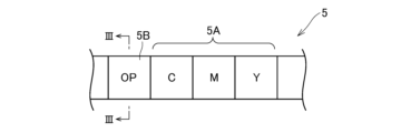
図1は本開示の実施の形態に係る熱転写印画装置の概略構成図であり、図2は熱転写印画装置で使用される熱転写シート5(インクリボン)の平面図であり、図3は図2のIII-III線断面図である。熱転写印画装置は、受像シート7にイエロー、マゼンタ、シアンの染料を昇華転写して、画像を印画する。印画する画像は、例えば、顔画像等の人物画像や、住所・氏名等の文字である。
Figure 1 is a schematic diagram of a thermal transfer printing device according to an embodiment of the present disclosure, Figure 2 is a plan view of a thermal transfer sheet 5 (ink ribbon) used in the thermal transfer printing device, and Figure 3 is a cross-sectional view taken along line III-III in Figure 2. The thermal transfer printing device prints an image by sublimation-transferring yellow, magenta, and cyan dyes onto an image-
受像シート7は、受像紙ロール6に巻き付けられており、受像紙ロール6から繰り出される。受像シート7には公知のものを使用することができる。受像紙ロール6、キャプスタンローラ9a、及びピンチローラ9bを含む駆動部12により受像シート7の繰り出しや巻取りが行われる。
The
熱転写印画装置で使用される熱転写シート5は、基材51(図3参照)上に面順次に設けられた染料層5A及び保護層5Bを有する。染料層5Aは、面順次に設けられたイエロー染料を含むY層、マゼンタ染料を含むM層、シアン染料を含むC層を有する。
The
図3に示すように、保護層5Bが設けられた領域では、熱転写シート5は、基材51と、基材51の一方の面側に順に積層された粘着層52及び保護層5Bと、基材51の他方の面側に設けられた背面層55とを有する。保護層5Bは、粘着層52上に位置する剥離層53と、剥離層53上に設けられた接着層54とを含み、受像シート7に転写される転写層である。
As shown in FIG. 3, in the region where the
なお、上述した染料層5Aが形成された領域には、背面層55は設けられているが、粘着層52は設けられていない。
In addition, in the area where the
熱転写印画装置は、熱転写シート5を加熱するサーマルヘッド1を備える。熱転写シート5は、供給部3から繰り出され、サーマルヘッド1を通って、回収部4に回収されるようになっている。回収部4は、染料層5A(及び保護層5B)を内側、背面層55を外側とするように、熱転写シート5を巻き取る。
The thermal transfer printing device is equipped with a thermal head 1 that heats a
サーマルヘッド1の下方側には回転自在なプラテンロール2が設けられている。サーマルヘッド1及びプラテンロール2を含む印画部10は、受像シート7及び熱転写シート5を挟み込み、サーマルヘッド1が熱転写シート5を背面層55側から加熱して、印画処理を行う。
A freely
制御装置14は、熱転写印画装置の各部の駆動を制御し、印画処理を行う。印画処理では、まず、染料層5Aのイエロー染料層、マゼンタ染料層及びシアン染料層の各層を順に加熱して、熱転写シート5から受像シート7に染料を移行して画像を形成する。
The
次に、熱転写シート5から、受像シート7に形成された画像を覆うように保護層5Bを転写する。保護層5Bが転写された受像シート7は下流側でカッター8によりプリント枚葉7aとして切り出される。プリント枚葉7aは、図示を省略する排出口から排出される。
Next, a
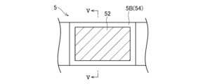
保護層5Bの転写後、熱転写シート5の保護層転写領域(転写された保護層5Bが設けられていた領域)では、図4、図5に示すように、保護層5Bの下方に位置する粘着層52の表面が露出する。
After the
保護層転写後の使用済みの熱転写シート5は、バッファ部20を通過し、回収部4で巻き取られる。図6に示すように、表面が露出した粘着層52が、内周側の熱転写シート5の背面層55と接着する。粘着層52で接着させ一体化した使用済みの熱転写シート5は剥がすことが極めて困難であり、無理矢理剥がそうとした場合は熱転写シート5が破断する。そのため、印画情報の漏洩を防止できる。
After the protective layer is transferred, the used
サーマルヘッド1と回収部4との間には、熱転写後の使用済み熱転写シート5の搬送量を調整するバッファ部20が設けられている。バッファ部20は、熱転写シート5の背面層55側に接触するローラ21を有し、ローラ21は熱転写シート5の厚み方向に移動可能になっている。
Between the thermal head 1 and the
図7aは、熱転写シート5を順方向に搬送する際のローラ21の位置を示し、図7bは、熱転写シート5を逆方向に搬送する際のローラ21の位置を示す。ここで、順方向は、熱転写シート5が回収部4へ進む方向であり、熱転写シート5は回収部4で巻き取られる。逆方向は、供給部3が逆回転して熱転写シート5を巻き戻し、熱転写シート5が供給部3へ進む(戻る)方向である。
Figure 7a shows the position of
図7a、図7bに示すように、順方向搬送時は、逆方向搬送時よりもサーマルヘッド1と回収部4との間の搬送経路が長くなっている。
As shown in Figures 7a and 7b, when transporting in the forward direction, the transport path between the thermal head 1 and the
印画処理の方式によっては、順方向に搬送した熱転写シート5を、逆方向へ所定量搬送することがある。熱転写シート5を逆方向へ搬送する場合は、ローラ21を移動させ、サーマルヘッド1と回収部4との間の搬送経路上にあった熱転写シート5が搬送されるようにする。これにより、回収部4において接着した熱転写シート5を剥がすことなく、熱転写シート5を逆方向に搬送できる。
Depending on the printing process method, the
熱転写シート5は、図8に示すように、粘着層52上に設けられた溶融転写層5Cを備えていてもよい。溶融転写層5Cは、粘着層52上に位置する剥離層53と、剥離層53上に設けられた溶融インク層56を有する。溶融インク層56は、カーボンブラック等の顔料をバインダー樹脂に分散させたものである。
As shown in FIG. 8, the
溶融転写層5Cは、受像シート7上に文字などのパターンで転写される。溶融転写層5Cの転写後、熱転写シート5の溶融転写層転写領域(転写された溶融転写層5Cが設けられていた領域)では、図9に示すように、溶融転写層5Cの下方に位置する粘着層52の表面が露出する。
The
溶融転写層を転写した後の使用済みの熱転写シート5は、回収部4で巻き取られ、表面が露出した粘着層52が、内周側の熱転写シート5の背面層55と接着する。使用済みの熱転写シート5は、粘着層52で接着して一体化するため、印画情報の漏洩を防止できる。熱転写シート5は、保護層5Bと溶融転写層5Cの少なくともいずれか一方を有する。
After the melt transfer layer has been transferred, the used
回収部4の近傍に、回収部4に巻き取られて回収された熱転写シート5の背面層55を内周側へ押圧するローラを設けてもよい。これにより、粘着層52と背面層55とがより強固に接着する。
A roller may be provided near the
上記実施形態では、表面が露出した粘着層52が、内周側の熱転写シート5の背面層55と接着するように、回収部4が熱転写シート5を内巻きで回収する例について説明したが、表面が露出した粘着層52が、外周側の熱転写シート5の背面層55と接着するように、回収部4が熱転写シート5を外巻きで回収してもよい。この場合、表面に離型性を有する押圧ローラを回収部4の近傍に設け、巻き取られた熱転写シート5を内周側へ押圧することが好ましい。
In the above embodiment, an example was described in which the
次に、熱転写シート5を構成する材料について説明する。
Next, we will explain the materials that make up the
(基材)
熱転写シート5の基材51としては、従来公知のある程度の耐熱性と強度を有するものであればいずれのものでも良く、例えば、ポリエチレンテレフタレートフィルム、1,4-ポリシクロヘキシレンジメチレンテレフタレートフィルム、ポリエチレンナフタレートフィルム、ポリフェニレンサルファイドフィルム、ポリスチレンフィルム、ポリプロピレンフィルム、ポリサルホンフィルム、アラミドフィルム、ポリカーボネートフィルム、ポリビニルアルコールフィルム、セロハン、酢酸セルロース等のセルロース誘導体、ポリエチレンフィルム、ポリ塩化ビニルフィルム、ナイロンフィルム、ポリイミドフィルム、アイオノマーフィルム等の樹脂フィルムの他に、コンデンサー紙、パラフィン紙等の紙類や不織布等、又は紙や不織布と樹脂との複合体であってもよい。
(Substrate)
The
基材の厚みは、特に限定されないが、0.5μm以上50μm以下程度が好ましい。 The thickness of the substrate is not particularly limited, but is preferably 0.5 μm or more and 50 μm or less.
(染料層)
染料層5Aは、昇華性染料を含む層として形成する。染料としては、公知の熱転写シートに使用されている染料は、いずれも使用可能であり、特に限定されない。これらの染料としてはジアリールメタン系、トリアリールメタン系、チアゾール系、メロシアニン等のメチン系、インドアニリン系、アセトフェノンアゾメチン,ピラゾロアゾメチン,イミダゾルアゾメチン,ピリドンアゾメチン等のアゾメチン系、キサンテン系、オキサジン系、ジシアノスチレン,トリシアノスチレンに代表されるシアノメチレン系、チアジン系、アジン系、アクリジン系、ベンゼンアゾ系、ピリドンアゾ,チオフェンアゾ,イソチアゾールアゾ,ピロールアゾ,ピラゾールアゾ,イミダゾールアゾ,チアジアゾールアゾ,トリアゾールアゾ,ジスアゾ等のアゾ系、スピロピラン系、インドリノスピロピラン系、フルオラン系、ローダミンラクタム系、ナフトキノン系、アントラキノン系、キノフタロン系等があげられる。
(Dye layer)
The
染料層は、基材の一方の面に、これらの染料及びバインダー樹脂、必要に応じて顔料、導電剤の少なくとも1つを添加して、トルエン、メチルエチルケトン、エタノール、イソプロピルアルコール、シクロヘキサノン、DMF等の適当な有機溶剤に溶解したり、あるいは有機溶剤や水等に分散させたりして、例えば、グラビア印刷法、スクリーン印刷法、リバースロールコーティング印刷法等の手段により塗布および乾燥することにより形成できる。染料層の厚みは、乾燥後の厚みで0.2μm以上6.0μm以下程度である。 The dye layer can be formed by adding these dyes and binder resins, and optionally at least one of pigments and conductive agents, to one side of the substrate, dissolving them in a suitable organic solvent such as toluene, methyl ethyl ketone, ethanol, isopropyl alcohol, cyclohexanone, or DMF, or dispersing them in an organic solvent or water, and applying and drying them by means of, for example, gravure printing, screen printing, or reverse roll coating printing. The thickness of the dye layer after drying is approximately 0.2 μm or more and 6.0 μm or less.
(粘着層)
粘着層52を形成する粘着剤は、特に限定されず、従来公知の溶剤系や水系の粘着剤を用いることができる。粘着剤としては、例えば、酢酸ビニル樹脂、アクリル樹脂、酢酸ビニル-アクリル共重合体、酢酸ビニル-塩化ビニル共重合体、エチレン-酢酸ビニル共重合体、エチレン-アクリル酸共重合体、エチレン-アクリル酸エステル共重合体、ポリウレタンや、天然ゴム、クロロプレンゴム、ニトリルゴムなどが挙げられる。
(Adhesive layer)
There are no particular limitations on the adhesive that forms the
粘着層の厚さは、1μm以上20μm以下程度である。 The thickness of the adhesive layer is approximately 1 μm or more and 20 μm or less.
回収部4に巻き取られた際の内周側の背面層55との接着性を考慮すると、粘着層の粘着力は、保護層転写後に露出した粘着層表面に離型紙を貼り合わせて剥がす時の剥離力が20gf/cm以上となることが好ましい。なお、粘着層と背面層とを貼り合わせて剥がすと、剥離力が大きすぎて熱転写シートが破断してしまう。
Considering the adhesive strength with the inner
(保護層)
保護層5Bは、剥離層53及び接着層54を有する。
(Protective Layer)
The
接着層54は、保護層5Bの転写性と、転写後の保護層5Bの画像面に対する密着性を向上させる。この接着層は、従来公知の感熱接着剤がいずれも使用できるが、ガラス転移温度が50℃以上100℃以下の熱可塑性樹脂から形成することがより好ましく、例えば、紫外線吸収性樹脂、アクリル樹脂、塩化ビニル-酢酸ビニル共重合体、エポキシ樹脂、ポリエステル、ポリカーボネート、ブチラール樹脂、ポリアミド、ポリ塩化ビニルなどの如く熱時接着性の良好な樹脂から、適当なガラス転移温度を有するものを選択することが好ましい。
The
接着層は、上述した材料の中から選択される単独または複数の樹脂材料、さらに必要に応じて、添加剤を加え、有機溶剤等の適当な溶剤に溶解または分散させて接着層用塗工液を調製し、これをグラビア印刷法、スクリーン印刷法またはグラビア版を用いたリバースコーティング法等の手段により、塗布、乾燥して形成することができる。接着層の厚さは特に限定はないが、通常、乾燥状態で0.3μm以上10μm以下程度である。 The adhesive layer can be formed by preparing a coating liquid for the adhesive layer by dissolving or dispersing one or more resin materials selected from the above-mentioned materials, and, if necessary, adding additives, in an appropriate solvent such as an organic solvent, and then coating and drying this by means of a method such as gravure printing, screen printing, or reverse coating using a gravure plate. There is no particular limit to the thickness of the adhesive layer, but it is usually about 0.3 μm to 10 μm in the dry state.
剥離層53は、熱転写時に粘着層52から保護層5Bを剥離し易くするものであり、熱転写時に被転写体上に転写される層である。
The
剥離層は、例えば、シリコーンワックス等の各種ワックス類、シリコーン樹脂、フッ素樹脂、アクリル樹脂、水溶性樹脂、セルロース誘導体樹脂、ポリウレタン、酢酸系ポリビニル、アクリルビニルエーテル樹脂、無水マレイン酸樹脂等の各種樹脂等やこれらの混合物から構成される。 The release layer is composed of various resins such as silicone wax, silicone resin, fluororesin, acrylic resin, water-soluble resin, cellulose derivative resin, polyurethane, acetate-based polyvinyl, acrylic vinyl ether resin, maleic anhydride resin, and mixtures thereof.
剥離層は、上記ワックス類及び上記樹脂からなる群より選ばれる少なくとも1種を含有する塗工液を、従来公知の塗布方法に従って粘着層上に塗布し、乾燥することで形成できる。剥離層の厚みは、乾燥後の厚みで0.5μm以上5μm以下程度である。 The release layer can be formed by applying a coating liquid containing at least one selected from the group consisting of the above waxes and the above resins onto the adhesive layer according to a conventionally known coating method, and then drying the coating liquid. The thickness of the release layer after drying is approximately 0.5 μm or more and 5 μm or less.
(背面層)
背面層55は、基材51の染料層5A及び保護層5Bが設けられた面とは反対側の面(裏面)に設けられ、サーマルヘッド等の加熱デバイスと基材との熱融着を防止し、走行を滑らかにする。
(Back layer)
The
背面層55を形成する樹脂としては、例えば、ポリビニルブチラール、ポリビニルアセトアセタール、ポリエステル、塩化ビニル-酢酸ビニル共重合体、ポリエーテル、ポリブタジエン、スチレン-ブタジエン共重合体、アクリルポリオール、ポリウレタンアクリレート、ポリエステルアクリレート、ポリエーテルアクリレート、エポキシアクリレート、ウレタン又はエポキシのプレポリマー、ニトロセルロース樹脂、セルロースナイトレート樹脂、セルロースアセトプロピオネート樹脂、セルロースアセテートブチレート樹脂、セルロースアセテートヒドロジエンフタレート樹脂、酢酸セルロース樹脂、ポリアミド、ポリイミド、ポリアミドイミド、ポリカーボネート、塩素化ポリオレフィン等が挙げられる。
Examples of resins that form the
上述したように、回収部4において、粘着層52の表面露出部分と、内周側の熱転写シート5の背面層55とが接着する。粘着層52との接着面積を大きくし、接着性を良好にするために、背面層55は、固体フィラーの含有量を少なくし、表面が平滑になるようにすることが好ましい。
As described above, in the
背面層55の表面の十点平均粗さRzは5.0μm以下が好ましく、4.0μm以下がより好ましく、3.0μm以下がさらに好ましい。例えば、表面粗さ測定機(サーフコム 1400 3DF (株)東京精密製)を使用し、以下の測定条件で表面粗さを測定することができる。
<測定条件>
・測定方法;2次元
・測定範囲;4mm
・測定ピッチ;20μm
・測定倍率;20K
・λsフィルタ;無し
・カットオフ種別;ガウシアン
・カットオフ波長;0.8mm
・傾斜補正;最小自乗直線
・測定速度;0.6mm/s
・ピックアップ種別;標準ピックアップ
The ten-point average roughness Rz of the surface of the
<Measurement conditions>
Measurement method: 2-dimensional Measurement range: 4 mm
Measurement pitch: 20 μm
Measurement magnification: 20K
λs filter: None; Cutoff type: Gaussian; Cutoff wavelength: 0.8 mm
・Inclination correction: Least squares straight line ・Measurement speed: 0.6mm/s
Pickup type: Standard pickup
背面層55は、上述した樹脂を、適当な溶剤により溶解または分散させて、背面層用塗工液を調製し、これを、基材51の裏面に、例えば、グラビア印刷法、スクリーン印刷法、グラビア版を用いたリバースコーティング法などの形成手段により塗布し、乾燥して形成することができる。背面層55の厚みは、乾燥後の厚みで0.1μm以上2μm以下程度である。
The
次に実施例を挙げて本開示を更に具体的に説明するが、本開示は、これら実施例に限定されるものではない。なお、文中の「部」は特に断りのない限り質量基準である。 The present disclosure will now be described in more detail with reference to examples, but the present disclosure is not limited to these examples. Note that "parts" in the text are by weight unless otherwise specified.
[実施例1]
基材として厚さ5μmのPETフィルムを用い、この基材の一方の面に、下記組成の粘着層用塗工液を塗布、乾燥し、厚さ2μmの粘着層を形成した。この粘着層上に、下記組成の剥離層用塗工液を塗布、乾燥し、厚さ0.5μmの剥離層を形成した。この剥離層上に、下記組成の接着層用塗工液を塗布、乾燥し、厚さ0.5μmの接着層を形成し、積層された剥離層及び接着層を有する保護層を得た。基材の他方の面に、下記組成の背面層用塗工液1を塗布、乾燥し、厚さ1μmの背面層を形成し、背面層、基材、粘着層、保護層(剥離層及び接着層)がこの順に積層された実施例1の熱転写シートを作製した。
[Example 1]
A PET film having a thickness of 5 μm was used as the substrate, and a coating liquid for adhesive layer having the following composition was applied to one side of the substrate and dried to form an adhesive layer having a thickness of 2 μm. A coating liquid for peeling layer having the following composition was applied to this adhesive layer and dried to form a peeling layer having a thickness of 0.5 μm. A coating liquid for adhesive layer having the following composition was applied to this peeling layer and dried to form an adhesive layer having a thickness of 0.5 μm, and a protective layer having a laminated peeling layer and adhesive layer was obtained. A coating liquid 1 for back layer having the following composition was applied to the other side of the substrate and dried to form a back layer having a thickness of 1 μm, and a thermal transfer sheet of Example 1 in which the back layer, substrate, adhesive layer, and protective layer (peeling layer and adhesive layer) were laminated in this order was produced.
<粘着層用塗工液>
・アクリル共重合体 15部
(SKダイン1251 綜研化学(株))
・硬化剤 0.33部
(L-45 綜研化学(株))
・硬化剤 0.1部
(E-AX 綜研化学(株))
・酢酸エチル 16.14部
<Coating solution for adhesive layer>
Hardener 0.33 parts (L-45, Soken Chemical Industries, Ltd.)
・0.1 parts of hardener (E-AX, Soken Chemical Industries, Ltd.)
Ethyl acetate 16.14 parts
<剥離層用塗工液>
・シリコーン剥離剤 10部
(KS-847H 信越化学工業(株))
・メチルエチルケトン 40部
・トルエン 40部
<Coating solution for release layer>
・
・Methyl ethyl ketone 40 parts ・Toluene 40 parts
<接着層用塗工液>
・ポリエステル樹脂 20部
(バイロン200 東洋紡(株))
・紫外線吸収剤共重合樹脂 10部
(UVA-635L BASFジャパン社製)
・メチルエチルケトン 80部
<Coating solution for adhesive layer>
20 parts of polyester resin (Vylon 200, Toyobo Co., Ltd.)
Ultraviolet absorbing
・Methyl ethyl ketone 80 parts
<背面層用塗工液1>
・ポリビニルアセタール樹脂 60部
(エスレックKS-1 積水化学工業(株))
・ポリイソシアネート 4部
(バーノックD750 大日本インキ化学工業(株))
・フィラー(ステアリルリン酸亜鉛) 10部
(LBT1830精製 堺化学工業(株))
・フィラー(ステアリン酸亜鉛) 10部
(SZ-PF 堺化学工業(株))
・フィラー(ポリエチレンワックス) 3部
(ポリワックス3000 東洋アドレ(株))
・フィラー(エトキシ化アルコール変性ワックス) 7部
(ユニトックス750 東洋アドレ(株))
・トルエン 200部
・メチルエチルケトン 100部
<Back layer coating liquid 1>
Polyvinyl acetal resin 60 parts (S-LEC KS-1, Sekisui Chemical Co., Ltd.)
Filler (zinc stearyl phosphate) 10 parts (LBT1830 refined, Sakai Chemical Industry Co., Ltd.)
Filler (zinc stearate) 10 parts (SZ-PF Sakai Chemical Industry Co., Ltd.)
Filler (polyethylene wax) 3 parts (Polywax 3000, Toyo Adle Co., Ltd.)
Filler (ethoxylated alcohol-modified wax) 7 parts (Unitox 750, Toyo Adle Co., Ltd.)
・Toluene 200 parts ・Methyl ethyl ketone 100 parts
<保護層の転写>
作製された熱転写シートを使用し、下記テストプリンタにて、大日本印刷(株)の熱転写プリンタ(DS620)用受像紙へ保護層を転写した。
<Transfer of Protective Layer>
Using the prepared thermal transfer sheet, the protective layer was transferred onto image receiving paper for a thermal transfer printer (DS620) manufactured by Dai Nippon Printing Co., Ltd., using the following test printer.
<<テストプリンタ>>
・サーマルヘッド:F3598(東芝ホクト電子(株)製)
・発熱体平均抵抗値:5015(Ω)
・主走査方向印字密度:300(dpi)
・副走査方向印字密度:300(dpi)
・印加電圧:20(V)
・ライン周期:2.0(msec./line)
・パルスDuty:85%
<<Test Printer>>
Thermal head: F3598 (Toshiba Hokuto Electronics Co., Ltd.)
Heating element average resistance: 5015 (Ω)
Print density in the main scanning direction: 300 (dpi)
Sub-scanning direction print density: 300 (dpi)
Applied voltage: 20 (V)
Line period: 2.0 (msec./line)
Pulse Duty: 85%
<剥離力測定>
コート紙(厚み80μm)の一方の面に、上記剥離層用塗工液と同じ組成の離型層用塗工液を塗布、乾燥し、厚さ0.3μmの離型層を形成して、離型紙を得た。この離型紙を、保護層転写により露出した粘着層の表面に貼り合わせ、剥離装置(HEIDON-14DR 新東科学(株))を用いて、引っ張り速度2000mm/minで180°剥離を行って、そのときの剥離力を測定した。結果を表1に示す。
<Peel Force Measurement>
A release layer coating liquid having the same composition as the release layer coating liquid was applied to one side of a coated paper (thickness 80 μm) and dried to form a release layer having a thickness of 0.3 μm, thereby obtaining a release paper. This release paper was attached to the surface of the adhesive layer exposed by the protective layer transfer, and a peeling device (HEIDON-14DR, Shinto Scientific Co., Ltd.) was used to perform 180° peeling at a pulling speed of 2000 mm/min, and the peel force at that time was measured. The results are shown in Table 1.
<情報隠蔽性評価>
保護層転写により露出した粘着層の表面に、熱転写シートの背面層を貼り合わせた後、粘着層から背面層が剥がれるか確認し、剥がれにくさを下記の基準で評価した。結果を表1に示す。
<Information concealment evaluation>
After laminating the back layer of the thermal transfer sheet to the surface of the adhesive layer exposed by the protective layer transfer, it was confirmed whether the back layer could be peeled off from the adhesive layer, and the peel resistance was evaluated according to the following criteria. The results are shown in Table 1.
「評価基準」
A:全く剥がれない。
B:わずかに剥がれるが、さらに剥がそうとするとリボンが破れる。
C:一部剥がれるが、さらに剥がそうとするとリボンが破れる。
D:剥がれるが抵抗があり、さらに剥がそうとするとリボンが破れる。
E:容易に剥がれる
"Evaluation Criteria"
A: It does not peel off at all.
B: The ribbon peels off slightly, but if you try to peel it off further the ribbon breaks.
C: Part of the ribbon peels off, but if you try to peel it off further the ribbon breaks.
D: The ribbon can be peeled off, but there is resistance, and if you try to peel it off further the ribbon breaks.
E: Peels off easily
[実施例2~6、比較例1~2]
背面層用塗工液の組成、粘着層の厚み、保護層転写時の印加電圧のうち、少なくともいずれか1つを変更した以外は、実施例1と同様にして熱転写シートを作製し、保護層を転写して、評価を行った。結果を表1に示す。
[Examples 2 to 6, Comparative Examples 1 to 2]
A thermal transfer sheet was prepared in the same manner as in Example 1, except that at least one of the composition of the coating liquid for the back layer, the thickness of the adhesive layer, and the voltage applied during the transfer of the protective layer was changed, and the protective layer was transferred and evaluated. The results are shown in Table 1.
<背面層用塗工液2>
・ポリビニルブチラール樹脂 1.8部
(エスレック(登録商標)BX-1 積水化学工業(株))
・ポリイソシアネート 5.5部
(バーノック(登録商標)D750 DIC(株))
・リン酸エステル系界面活性剤 1.6部
(プライサーフ(登録商標)A208N 第一工業製薬(株))
・タルク 0.35部
(ミクロエース(登録商標)P-3 日本タルク工業(株))
・トルエン 18.5部
・メチルエチルケトン 18.5部
<Back
Polyvinyl butyral resin 1.8 parts (S-LEC (registered trademark) BX-1, Sekisui Chemical Co., Ltd.)
Polyisocyanate 5.5 parts (Burnoc (registered trademark) D750 DIC Corporation)
Phosphate ester surfactant 1.6 parts (Plysurf (registered trademark) A208N, Daiichi Kogyo Seiyaku Co., Ltd.)
Talc 0.35 parts (Microace (registered trademark) P-3, Nippon Talc Kogyo Co., Ltd.)
Toluene 18.5 parts Methyl ethyl ketone 18.5 parts

各実施例の熱転写シートについて、背面層の表面の十点平均粗さRzを、表面粗さ測定機(サーフコム 1400 3DF (株)東京精密製)を用いて、上記の測定条件で測定した。実施例1,3,5の熱転写シートの背面層の表面の十点平均粗さRzは4.8μm、実施例2,4,6の熱転写シートの背面層の表面の十点平均粗さRzは2.0μm以下であった。 For the thermal transfer sheets of each Example, the ten-point average roughness Rz of the surface of the back layer was measured under the above measurement conditions using a surface roughness measuring instrument (Surfcom 1400 3DF, manufactured by Tokyo Seimitsu Co., Ltd.). The ten-point average roughness Rz of the surface of the back layer of the thermal transfer sheets of Examples 1, 3, and 5 was 4.8 μm, and the ten-point average roughness Rz of the surface of the back layer of the thermal transfer sheets of Examples 2, 4, and 6 was 2.0 μm or less.
1 サーマルヘッド
2 プラテンロール
3 供給部
4 回収部
5 熱転写シート
5A 染料層
5B 保護層
7 受像シート
10 印画部
14 制御装置
20 バッファ部
51 基材
52 粘着層
53 剥離層
54 接着層
55 背面層
REFERENCE SIGNS LIST 1
Claims (2)
サーマルヘッドで前記熱転写シートを加熱し、受像シートに染料を移行して画像を形成し、前記画像の形成後、前記受像シート上に前記転写層を転写する工程と、
前記転写層を転写した後の熱転写シートを、表面が露出した前記粘着層が内周側の前記熱転写シートの前記背面層と接着するように回収部により内巻きで巻き取る工程と、
前記回収部に巻き取られて回収された前記熱転写シートの前記背面層をローラで内周側へ押圧する工程と、
を備える熱転写シートの残像処理方法。 A method for treating residual images of a thermal transfer sheet having a substrate, a dye layer and a transfer layer provided in surface sequence on one surface of the substrate , and a back layer provided on the other surface of the substrate, the method comprising the steps of:
a step of heating the thermal transfer sheet with a thermal head, transferring a dye to an image receiving sheet to form an image, and transferring the transfer layer onto the image receiving sheet after the image is formed ;
a step of inwardly winding the thermal transfer sheet after the transfer layer has been transferred by a recovery unit so that the adhesive layer having an exposed surface is adhered to the back surface layer of the thermal transfer sheet on the inner peripheral side;
a step of pressing the back surface layer of the thermal transfer sheet wound and collected in the collection section toward an inner periphery side with a roller;
A method for treating an afterimage on a thermal transfer sheet comprising:
サーマルヘッドで前記熱転写シートを加熱し、受像シートに染料を移行して画像を形成し、前記画像の形成後、前記受像シート上に前記転写層を転写する工程と、
前記転写層を転写した後の熱転写シートを、表面が露出した前記粘着層が外周側の前記熱転写シートの前記背面層と接着するように回収部により外巻きで巻き取る工程と、
前記回収部に巻き取られて回収された前記熱転写シートを、表面に離型性を有するローラで内周側へ押圧する工程と、
を備える熱転写シートの残像処理方法。 A method for treating residual images of a thermal transfer sheet having a substrate, a dye layer and a transfer layer provided in surface sequence on one surface of the substrate , and a back layer provided on the other surface of the substrate, the method comprising the steps of:
a step of heating the thermal transfer sheet with a thermal head, transferring a dye to an image receiving sheet to form an image, and transferring the transfer layer onto the image receiving sheet after the image is formed ;
a step of winding the thermal transfer sheet after the transfer layer has been transferred outwardly by a recovery section so that the adhesive layer on the exposed surface is adhered to the back layer of the thermal transfer sheet on the outer periphery;
a step of pressing the thermal transfer sheet, which has been wound up and collected in the collection section, toward an inner periphery with a roller having a releasable surface;
A method for treating an afterimage on a thermal transfer sheet comprising:
Priority Applications (1)
| Application Number | Priority Date | Filing Date | Title |
|---|---|---|---|
| JP2021038526A JP7608882B2 (en) | 2021-03-10 | 2021-03-10 | Method for removing residual images from thermal transfer sheets |
Applications Claiming Priority (1)
| Application Number | Priority Date | Filing Date | Title |
|---|---|---|---|
| JP2021038526A JP7608882B2 (en) | 2021-03-10 | 2021-03-10 | Method for removing residual images from thermal transfer sheets |
Publications (2)
| Publication Number | Publication Date |
|---|---|
| JP2022138574A JP2022138574A (en) | 2022-09-26 |
| JP7608882B2 true JP7608882B2 (en) | 2025-01-07 |
Family
ID=83399014
Family Applications (1)
| Application Number | Title | Priority Date | Filing Date |
|---|---|---|---|
| JP2021038526A Active JP7608882B2 (en) | 2021-03-10 | 2021-03-10 | Method for removing residual images from thermal transfer sheets |
Country Status (1)
| Country | Link |
|---|---|
| JP (1) | JP7608882B2 (en) |
Citations (6)
| Publication number | Priority date | Publication date | Assignee | Title |
|---|---|---|---|---|
| JP2000167970A (en) | 1998-12-04 | 2000-06-20 | Toppan Printing Co Ltd | Transfer protection film |
| JP2012101361A (en) | 2010-11-05 | 2012-05-31 | Sony Corp | Thermal transfer sheet, transfer object sheet and thermal transfer method |
| JP2013052643A (en) | 2011-09-06 | 2013-03-21 | Toshiba Tec Corp | Thermal transfer ribbon and thermal printer including the same |
| JP2016190373A (en) | 2015-03-31 | 2016-11-10 | 大日本印刷株式会社 | Thermal transfer sheet and printing method |
| WO2018151257A1 (en) | 2017-02-16 | 2018-08-23 | 大日本印刷株式会社 | Releasing member-integrated transfer sheet, and method for manufacturing said transfer sheet and printed matter |
| JP2018161844A (en) | 2017-03-27 | 2018-10-18 | 大日本印刷株式会社 | Thermal transfer printing device |
Family Cites Families (1)
| Publication number | Priority date | Publication date | Assignee | Title |
|---|---|---|---|---|
| JPH0999650A (en) * | 1995-10-06 | 1997-04-15 | Toppan Printing Co Ltd | Thermal transfer recording medium |
-
2021
- 2021-03-10 JP JP2021038526A patent/JP7608882B2/en active Active
Patent Citations (6)
| Publication number | Priority date | Publication date | Assignee | Title |
|---|---|---|---|---|
| JP2000167970A (en) | 1998-12-04 | 2000-06-20 | Toppan Printing Co Ltd | Transfer protection film |
| JP2012101361A (en) | 2010-11-05 | 2012-05-31 | Sony Corp | Thermal transfer sheet, transfer object sheet and thermal transfer method |
| JP2013052643A (en) | 2011-09-06 | 2013-03-21 | Toshiba Tec Corp | Thermal transfer ribbon and thermal printer including the same |
| JP2016190373A (en) | 2015-03-31 | 2016-11-10 | 大日本印刷株式会社 | Thermal transfer sheet and printing method |
| WO2018151257A1 (en) | 2017-02-16 | 2018-08-23 | 大日本印刷株式会社 | Releasing member-integrated transfer sheet, and method for manufacturing said transfer sheet and printed matter |
| JP2018161844A (en) | 2017-03-27 | 2018-10-18 | 大日本印刷株式会社 | Thermal transfer printing device |
Also Published As
| Publication number | Publication date |
|---|---|
| JP2022138574A (en) | 2022-09-26 |
Similar Documents
| Publication | Publication Date | Title |
|---|---|---|
| JP6765411B2 (en) | Release member integrated transfer sheet, photographic paper manufacturing method, transfer sheet manufacturing method, and printing system | |
| JP2008049663A (en) | Thermal transfer sheet afterimage processing method, thermal transfer sheet, and thermal transfer printer | |
| JP3802484B2 (en) | Thermal transfer sheet | |
| JP2000118144A (en) | Laser thermal transfer image formation method, ink sheet for forming laser thermal transfer image, and image receiving sheet for forming laser thermal transfer image | |
| JP7608882B2 (en) | Method for removing residual images from thermal transfer sheets | |
| JP2003080844A (en) | Protective layer thermal transfer sheet | |
| JP2000033780A (en) | Laser thermal transfer recording material and laser thermal transfer recording method | |
| JP2000071634A (en) | Method for forming image using intermediate transfer medium | |
| JP7631967B2 (en) | How to prevent information leakage from used thermal transfer sheets | |
| JP2020055287A (en) | Thermal transfer sheet, thermal transfer printer and cleaning method of thermal head | |
| JP2000127636A (en) | Image recording method using intermediate transfer medium for thermal transfer | |
| JPH11348438A (en) | Laser thermal transfer recording material and laser thermal transfer recording method | |
| JP3270955B2 (en) | Thermal transfer image receiving sheet | |
| JPH07205557A (en) | Thermal transfer image receiving sheet | |
| JP2687317B2 (en) | Dry lithographic continuous printing method and device | |
| JP2003165271A (en) | Method for forming image | |
| JP2000108526A (en) | Thermal transfer image protection media | |
| JP2000141723A (en) | Method for forming image | |
| JP2001010094A (en) | Laser thermal transfer recording method | |
| JP3254569B2 (en) | Thermal transfer image receiving sheet | |
| JP2000211222A (en) | Ink sheet, image receiving sheet, image forming device, image forming method, image forming system, and centralized control system for image forming device | |
| JPH11321137A (en) | Laser thermal transfer recording material and laser thermal transfer recording method | |
| JPH1178256A (en) | Sublimation type thermal transfer body and sublimation type thermal transfer recording method using the same | |
| JPH11170581A (en) | Laser thermal transfer image forming method | |
| JP3864576B2 (en) | Image forming method using intermediate transfer medium |
Legal Events
| Date | Code | Title | Description |
|---|---|---|---|
| A621 | Written request for application examination |
Free format text: JAPANESE INTERMEDIATE CODE: A621 Effective date: 20240129 |
|
| A131 | Notification of reasons for refusal |
Free format text: JAPANESE INTERMEDIATE CODE: A131 Effective date: 20240618 |
|
| A521 | Request for written amendment filed |
Free format text: JAPANESE INTERMEDIATE CODE: A523 Effective date: 20240809 |
|
| A131 | Notification of reasons for refusal |
Free format text: JAPANESE INTERMEDIATE CODE: A131 Effective date: 20240827 |
|
| A521 | Request for written amendment filed |
Free format text: JAPANESE INTERMEDIATE CODE: A523 Effective date: 20241025 |
|
| TRDD | Decision of grant or rejection written | ||
| A01 | Written decision to grant a patent or to grant a registration (utility model) |
Free format text: JAPANESE INTERMEDIATE CODE: A01 Effective date: 20241119 |
|
| A61 | First payment of annual fees (during grant procedure) |
Free format text: JAPANESE INTERMEDIATE CODE: A61 Effective date: 20241202 |
|
| R150 | Certificate of patent or registration of utility model |
Ref document number: 7608882 Country of ref document: JP Free format text: JAPANESE INTERMEDIATE CODE: R150 |