JP7608880B2 - Network equipment and network systems - Google Patents
Network equipment and network systems Download PDFInfo
- Publication number
- JP7608880B2 JP7608880B2 JP2021037851A JP2021037851A JP7608880B2 JP 7608880 B2 JP7608880 B2 JP 7608880B2 JP 2021037851 A JP2021037851 A JP 2021037851A JP 2021037851 A JP2021037851 A JP 2021037851A JP 7608880 B2 JP7608880 B2 JP 7608880B2
- Authority
- JP
- Japan
- Prior art keywords
- slave
- abnormality
- network
- network device
- notification
- Prior art date
- Legal status (The legal status is an assumption and is not a legal conclusion. Google has not performed a legal analysis and makes no representation as to the accuracy of the status listed.)
- Active
Links
Images


Classifications
-
- H—ELECTRICITY
- H04—ELECTRIC COMMUNICATION TECHNIQUE
- H04L—TRANSMISSION OF DIGITAL INFORMATION, e.g. TELEGRAPHIC COMMUNICATION
- H04L12/00—Data switching networks
- H04L12/28—Data switching networks characterised by path configuration, e.g. LAN [Local Area Networks] or WAN [Wide Area Networks]
-
- H—ELECTRICITY
- H04—ELECTRIC COMMUNICATION TECHNIQUE
- H04L—TRANSMISSION OF DIGITAL INFORMATION, e.g. TELEGRAPHIC COMMUNICATION
- H04L41/00—Arrangements for maintenance, administration or management of data switching networks, e.g. of packet switching networks
-
- Y—GENERAL TAGGING OF NEW TECHNOLOGICAL DEVELOPMENTS; GENERAL TAGGING OF CROSS-SECTIONAL TECHNOLOGIES SPANNING OVER SEVERAL SECTIONS OF THE IPC; TECHNICAL SUBJECTS COVERED BY FORMER USPC CROSS-REFERENCE ART COLLECTIONS [XRACs] AND DIGESTS
- Y02—TECHNOLOGIES OR APPLICATIONS FOR MITIGATION OR ADAPTATION AGAINST CLIMATE CHANGE
- Y02P—CLIMATE CHANGE MITIGATION TECHNOLOGIES IN THE PRODUCTION OR PROCESSING OF GOODS
- Y02P90/00—Enabling technologies with a potential contribution to greenhouse gas [GHG] emissions mitigation
- Y02P90/02—Total factory control, e.g. smart factories, flexible manufacturing systems [FMS] or integrated manufacturing systems [IMS]
Landscapes
- Engineering & Computer Science (AREA)
- Computer Networks & Wireless Communication (AREA)
- Signal Processing (AREA)
- Small-Scale Networks (AREA)
Description
本開示は、ネットワーク機器、及びこれを用いたネットワークシステムに関する。 This disclosure relates to a network device and a network system using the same.
ファクトリーオートメーション(Factory Automation:FA)の分野においては、作業の工程を分担する様々な種類の装置の制御が行われる。工場施設等一定の領域において作業に用いられる各種のコントローラ、リモートI/O、および製造装置を連携して動作させるために、これらの装置を接続する、フィールドネットワークとも呼ばれる産業用ネットワークが構築されている。 In the field of factory automation (FA), various types of devices that share the work process are controlled. In order to link together the various controllers, remote I/O, and manufacturing equipment used in work in a certain area such as a factory facility, an industrial network, also known as a field network, is constructed to connect these devices.
一般的な産業用ネットワークでは、各種のスレーブ装置と、マスタ装置などから構成されるマスタスレーブ方式が採用される。スレーブ装置は、工場内に設置される設備の制御あるいはデータ収集を行う装置である。マスタ装置は、これらのスレーブ装置を集中管理する、例えば(PLC:Programmable Logic Controller)と呼ばれる装置である。 General industrial networks use a master-slave system consisting of various slave devices and a master device. The slave devices are devices that control the equipment installed in the factory or collect data. The master device is a device called a PLC (Programmable Logic Controller), for example, that centrally manages these slave devices.
従来のネットワークシステムには、複数の各スレーブ装置がマスタ装置に制御されているか否かを判別するために、マスタ装置が複数の各スレーブ装置に対してPINGを送信する技術が知られている(例えば、下記特許文献1参照)。
In conventional network systems, a technique is known in which a master device sends a PING to each of a number of slave devices to determine whether each of the slave devices is being controlled by the master device (see, for example,
しかしながら、上記のような従来のネットワークシステムでは、異常がスレーブ装置に生じたときに、そのスレーブ装置の少なくとも一部の動作と当該スレーブ装置に連携する他のスレーブ装置の少なくとも一部の動作を直ちに停止させることが難しい場合があった。特に、従来のネットワークシステムでは、例えば、製造物の部品点数の増加や製造工程の細分化などに伴う生産ラインでのスレーブ装置の設置数が膨大な台数となった場合において、マスタ装置でのスレーブ装置に対する通信負荷が大きくなり、当該マスタ装置によるスレーブ装置の監視を円滑に行えないことがあった。この結果、従来のネットワークシステムでは、スレーブ装置に異常が生じたときに、その異常を生じたスレーブ装置の少なくとも一部の動作と当該スレーブ装置に連携する他のスレーブ装置の少なくとも一部の動作を直ちに停止させことが困難となることがあった。 However, in conventional network systems such as those described above, when an abnormality occurs in a slave device, it is sometimes difficult to immediately stop the operation of at least a portion of the slave device and at least a portion of the other slave devices linked to that slave device. In particular, in conventional network systems, when the number of slave devices installed on a production line becomes enormous due to an increase in the number of parts in a product or subdivision of the manufacturing process, for example, the communication load on the master device for the slave devices becomes large, and the master device may not be able to smoothly monitor the slave devices. As a result, in conventional network systems, when an abnormality occurs in a slave device, it is sometimes difficult to immediately stop the operation of at least a portion of the slave device with the abnormality and at least a portion of the other slave devices linked to that slave device.
本開示は上記の問題点を鑑みてなされたものであり、異常がスレーブ装置に生じたときでも、その異常を生じたスレーブ装置の少なくとも一部の動作と当該スレーブ装置に連携する他のスレーブ装置の少なくとも一部の動作を直ちに停止させることができるネットワーク機器、及びネットワークシステムを提供することを目的とする。 The present disclosure has been made in consideration of the above problems, and aims to provide a network device and a network system that, even when an abnormality occurs in a slave device, can immediately stop at least a portion of the operation of the slave device in which the abnormality occurs and at least a portion of the operation of other slave devices linked to that slave device.
本開示は、上述の課題を解決するために、以下の構成を採用する。 To solve the above problems, the present disclosure adopts the following configuration.
本開示の一側面に係るネットワーク機器は、マスタ装置と、前記マスタ装置により制御される複数のスレーブ装置が接続されるネットワークシステムに用いられるスレーブ装置であるネットワーク機器であって、他の前記スレーブ装置との間でデータの送受信を行う通信部と、当該ネットワーク機器と少なくとも1つの他の前記スレーブ装置とを含んだグループの構成リストを予め記憶する記憶部と、当該ネットワーク機器の各部を制御する制御部と、を備え、前記制御部は、前記通信部を通じて、前記構成リストに登録された他の前記スレーブ装置に対して、応答指示を送信し、前記応答指示に対する応答をしない他の前記スレーブ装置がある場合に、前記通信部を通じて、前記構成リストに登録された他の前記スレーブ装置に対して、その少なくとも一部の動作を停止させる旨の指示を送信するとともに、当該ネットワーク機器の少なくとも一部の動作を停止させる構成を備えている。 A network device according to one aspect of the present disclosure is a network device that is a slave device used in a network system to which a master device and multiple slave devices controlled by the master device are connected, and includes a communication unit that transmits and receives data to and from the other slave devices, a storage unit that prestores a configuration list of a group including the network device and at least one of the other slave devices, and a control unit that controls each part of the network device, and the control unit transmits a response instruction to the other slave devices registered in the configuration list through the communication unit, and if there is another slave device that does not respond to the response instruction, transmits an instruction to the other slave devices registered in the configuration list through the communication unit to stop at least a portion of the operation of the other slave devices, and stops at least a portion of the operation of the network device.
上記構成によれば、異常がスレーブ装置に生じたときでも、その異常を生じたスレーブ装置と当該スレーブ装置に連携する他のスレーブ装置の少なくとも一部の動作を直ちに停止させることができる。 With the above configuration, even if an abnormality occurs in a slave device, it is possible to immediately stop the operation of the slave device where the abnormality occurred and at least some of the other slave devices linked to that slave device.
上記一側面に係るネットワーク機器において、異常報知を実行する異常報知部を、さらに備え、前記制御部は、前記応答指示に対する応答をしない他の前記スレーブ装置がある場合に、前記異常報知部に異常報知を実行させる構成を備えていてもよい。 The network device according to the above aspect may further include an abnormality notification unit that executes an abnormality notification, and the control unit may be configured to cause the abnormality notification unit to execute an abnormality notification when there is another slave device that does not respond to the response instruction.
上記構成によれば、異常がスレーブ装置に生じたときに、その異常の発生を確実に報知することができる。 With the above configuration, when an abnormality occurs in a slave device, the occurrence of the abnormality can be reliably notified.
上記一側面に係るネットワーク機器において、前記異常報知部は、発光素子を有し、前記異常報知は前記発光素子の点灯により実行される構成を備えていてもよい。 In the network device according to the above aspect, the abnormality notification unit may have a light-emitting element, and the abnormality notification may be performed by lighting up the light-emitting element.
上記構成によれば、異常がスレーブ装置に生じたときに、その異常の発生を視認させることができる。 With the above configuration, when an abnormality occurs in a slave device, the occurrence of the abnormality can be visually confirmed.
上記一側面に係るネットワーク機器において、前記記憶部には、前記マスタ装置及び他の前記スレーブ装置の少なくともいずれかが登録された通知先リストが予め記憶され、前記制御部は、前記応答指示に対する応答をしない他の前記スレーブ装置がある場合に、前記通知先リストに登録された前記マスタ装置または前記スレーブ装置に対して、異常が生じた旨の通知を送信する構成を備えていてもよい。 In the network device according to one aspect described above, the storage unit may be configured to prestore a notification list in which at least one of the master device and the other slave devices is registered, and the control unit may be configured to transmit a notification that an abnormality has occurred to the master device or the slave device registered in the notification list when there is another slave device that does not respond to the response instruction.
上記構成によれば、異常がスレーブ装置に生じたときに、その異常の発生をマスタ装置またはスレーブ装置に通知することができる。 With the above configuration, when an abnormality occurs in a slave device, the occurrence of the abnormality can be notified to the master device or the slave device.
上記一側面に係るネットワーク機器において、前記通知先リストには、異常発生の表示を行う表示装置が更に登録されており、前記制御部は、前記応答指示に対する応答をしない他の前記スレーブ装置がある場合に、前記通知先リストに登録された前記表示装置に対して、異常が生じた旨の通知を送信する構成を備えていてもよい。 In the network device according to the above aspect, the notification destination list may further include a display device that displays the occurrence of an abnormality, and the control unit may be configured to send a notification that an abnormality has occurred to the display device registered in the notification destination list when there is another slave device that does not respond to the response instruction.
上記構成によれば、異常がスレーブ装置に生じたときに、その異常の発生を表示装置に通知することができる。 With the above configuration, when an abnormality occurs in the slave device, the occurrence of the abnormality can be notified to the display device.
また、本開示の一側面に係るネットワークシステムは、マスタ装置と、前記マスタ装置により制御される複数のスレーブ装置が接続されるネットワークシステムであって、上記いずれかのネットワーク機器が、前記スレーブ装置として接続されている構成を備えている。 A network system according to one aspect of the present disclosure is a network system to which a master device and a plurality of slave devices controlled by the master device are connected, and is configured such that any of the network devices described above is connected as the slave device.
上記構成によれば、異常がスレーブ装置に生じたときでも、その異常を生じたスレーブ装置と当該スレーブ装置に連携する他のスレーブ装置の少なくとも一部の動作を直ちに停止させることができるネットワークシステムを構成することが可能である。 With the above configuration, it is possible to configure a network system that can immediately stop the operation of the slave device in which the abnormality occurred and at least some of the other slave devices linked to that slave device, even if an abnormality occurs in the slave device.
本開示によれば、異常がスレーブ装置に生じたときでも、その異常を生じたスレーブ装置の少なくとも一部の動作と当該スレーブ装置に連携する他のスレーブ装置の少なくとも一部の動作を直ちに停止させることができるネットワーク機器、及びネットワークシステムを提供することができる。 The present disclosure provides a network device and a network system that can immediately stop, even when an abnormality occurs in a slave device, at least a portion of the operation of the slave device in which the abnormality occurs and at least a portion of the operation of other slave devices linked to that slave device.
§1 適用例
まず、図1及び図2を用いて、本開示が適用される場面の一例について説明する。図1は、本開示の実施形態に係るネットワークシステムの構成例を説明する説明図である。図2は、本開示の実施形態に係るネットワーク機器(スレーブ装置)を示す概略構成図である。尚、以下の説明では、スレーブ装置である、本実施形態のネットワーク機器が、図2に示されるように、他のスレーブ装置と同一の構成である場合を例示して説明する。また、本実施形態のネットワークシステム100において、複数のスレーブ装置として、例えば、8つのスレーブ装置2A、2B、2C、2D、2E、2F、2G、2H(以下、”2”にて総称する)を接続した場合を例示して説明する。また、スレーブ装置2が、本実施形態のネットワーク機器を構成する場合には、ネットワーク機器2Nともいう。
§1 Application Example First, an example of a scene to which the present disclosure is applied will be described with reference to FIG. 1 and FIG. 2. FIG. 1 is an explanatory diagram for explaining a configuration example of a network system according to an embodiment of the present disclosure. FIG. 2 is a schematic configuration diagram showing a network device (slave device) according to an embodiment of the present disclosure. In the following description, a case will be described in which the network device of the present embodiment, which is a slave device, has the same configuration as other slave devices as shown in FIG. 2. In addition, in the
本実施形態のネットワークシステム100は、マスタ装置1と、当該マスタ装置1に制御される複数のスレーブ装置2が接続されるネットワークシステムである。また、本実施形態のネットワーク機器2Nは、ネットワークシステム100に対して、1つの上記スレーブ装置2として接続される。本実施形態のネットワークシステム100では、例えば、1つのネットワーク機器2Nがスレーブ装置2として接続される。
The
また、本実施形態のネットワークシステム100は、情報処理装置3を備えている。ネットワークシステム100の管理者は、情報処理装置3を通じて、マスタ装置1及びスレーブ装置2の各種設定の実行、データの取得等を行うことが可能になっている。さらに、本実施形態のネットワークシステム100は、表示装置4を備えており、当該ネットワークシステム100での動作状況などを表示可能になっている。
The
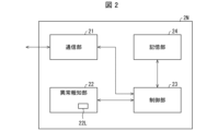
また、本実施形態のネットワーク機器2Nは、他のスレーブ装置2との間でデータの送受信を行う通信部21と、異常報知を実行する異常報知部22と、当該ネットワーク機器2Nと少なくとも1つの他のスレーブ装置2とを含んだ制御グループ(グループ)の構成リストを予め記憶する記憶部24と、当該ネットワーク機器2Nの各部(構成要素)を制御する制御部23とを備える。記憶部24には、上記情報処理装置3により、上述の制御グループの構成リストを含んだ所定の設定情報が予め設定される。
The
制御部23は、通信部21を通じて、上記構成リストに登録された他のスレーブ装置2対して、応答指示を送信する。その後、制御部23は、通信部21を通じて、応答指示に対する応答をしない他のスレーブ装置2がある場合に、通信部21を通じて、上記構成リストに登録された他のスレーブ装置2に対して、その少なくとも一部の動作を停止させる旨の指示を送信する。更には、制御部23は、当該ネットワーク機器2Nの少なくとも一部の動作を停止させる。
The
よって本実施形態によれば、異常がスレーブ装置2に生じたときでも、その異常を生じたスレーブ装置2の少なくとも一部の動作と当該スレーブ装置2に連携する他のスレーブ装置2の少なくとも一部の動作を直ちに停止させることができるネットワーク機器2N及びこれを用いたネットワークシステム100を構成することができる。
According to this embodiment, it is possible to configure a
§2 構成例
<ネットワークシステム>
図1の例では、本実施形態のネットワークシステム100は、マスタ装置1と、通信装置(通信ハブ)5A、5Bを介してマスタ装置1に接続される複数のスレーブ装置2と、通信装置5Aを介してマスタ装置1に接続される情報処理装置3及び表示装置4とを備える。また、本実施形態のネットワークシステム100では、例えば、ETHERNET/IP規格のネットワークシステムが用いられている(ETHERNET:登録商標)。また、本実施形態のネットワークシステム100では、例えば、通信ケーブルを使用して、マスタ装置1、スレーブ装置2、情報処理装置3、表示装置4、及び通信装置5A、5Bが図1に例示するように接続されており、通信ケーブルを介在させて通信を行うようになっている。
§2 Configuration example <Network system>
In the example of Fig. 1, the
マスタ装置1は、例えば、PLC(Programmable Logic Controller)を含んでいる。また、マスタ装置1は、情報処理装置3から設定される所定のプログラムに従って、動作することにより、複数の各スレーブ装置2の制御を行うように構成されている。
The
例えば、4つのスレーブ装置2A、2B、2C、2Dが通信装置5Bに対して順次接続され、4つのスレーブ装置2E、2F、2G、2Hが通信装置5Bに対して順次接続されている。また、スレーブ装置2では、情報処理装置3から設定される制御グループの構成リストに基づいて、例えば、図1に点線にて囲むように、2つの制御グループC1、C2にグループ分けされている。すなわち、制御グループC1には、4つのスレーブ装置2A、2B、2C、2Dが含まれ、制御グループC2には、4つのスレーブ装置2E、2F2G、2Hが含まれている。
For example, four
さらに、例えば、制御グループC1では、1つのスレーブ装置2Aが情報処理装置3からの上記設定情報Siを予め保持することによって、当該制御グループC1でのネットワーク機器2Nを構成するようになっている。そして、このネットワーク機器2Nは、マスタ装置1に代えて、制御グループC1の構成リストに登録されたスレーブ装置2B、2C、2Dを監視し、いずれかのスレーブ装置2に異常が生じたときに、制御グループC1の構成リストの全てのスレーブ装置2の少なくとも一部の動作を停止させるように構成されている(詳細は後述)。
Furthermore, for example, in the control group C1, one
尚、制御グループに含めるスレーブ装置2は、例えば、本実施形態のネットワークシステム100が工場の製造設備に適用される場合、その製造設備に含まれる生産ライン単位や製造物の生産処理単位などの異常を生じたスレーブ装置2の影響範囲を考慮して決定すると好ましい。つまり、このような場合には、異常を発生したスレーブ装置2とそれに連携するスレーブ装置2とを早急に確認することができ、さらには当該異常に対する処置を迅速に行うことが可能となって製造物の生産効率が低下するのを容易に防ぐことができるようになる。
When the
情報処理装置3は、例えば、コンピュータ(PC)を用いて構成されており、ユーザーによって操作されることにより、マスタ装置1、スレーブ装置2、及び表示装置4の各部を制御する。また、情報処理装置3は、ユーザーの操作に応じて、例えば、制御グループC1に含まれたスレーブ装置2Aに対して、制御グループC1での設定情報Siを予め設定して、このスレーブ装置2Aを制御グループC1でのネットワーク機器2Nとする。このように、本実施形態のネットワークシステム100では、情報処理装置3が、ユーザーによって適宜操作されることにより、各制御グループC1、C2でのスレーブ装置2の構成やネットワーク機器2の設定を自在に変更することができる。
The information processing device 3 is configured using, for example, a computer (PC), and is operated by a user to control each part of the
また、情報処理装置3は、ユーザーの操作に応じて、マスタ装置1または表示装置4の少なくとも一方に対して、スレーブ装置2に異常が発生した場合でのマスタ装置1または表示装置4の少なくとも一方における動作を指示する動作設定情報を予め設定するように構成されている。具体的には、情報処理装置3は、スレーブ装置2に異常が発生した場合において、動作設定情報を予め設定することにより、マスタ装置1の動作を停止させたり、表示装置4に異常発生の表示をさせたりすることができる。
The information processing device 3 is also configured to preset, in response to a user's operation, operation setting information for at least one of the
表示装置4は、例えば、タッチパネル機能を有する、液晶パネルや有機ELパネル等を用いて構成されている。また、表示装置4は、例えば、HMI(Human Machine Interface)に基づいて動作することにより、所定の情報表示や指示などの入力操作を行うようになっている。
The
<ネットワーク機器>
図2の例では、本実施形態のネットワーク機器2Nは、通信部21、異常報知部22、制御部23、及び記憶部24を備える。また、本実施形態のネットワーク機器2Nは、記憶部24に予め記憶されている設定情報Siに基づいて、制御グループの他のスレーブ装置2との間で通信を行うことにより、当該他のスレーブ装置2に異常が生じたか否かについて判別する。
<Network devices>
2, the
通信部21は、ネットワークシステム100の他機との間で双方向の通信を行う機能ブロックである。すなわち、ネットワーク機器2Nは、通信部21を通じて、上述の他機との間で、例えば、応答指示やその応答指示に対する応答などのデータを送受信する。また、ネットワーク機器2では、上記応答指示と応答として、例えば、PINGコマンドが用いられている。
The
異常報知部22は、例えば、発光素子としてのLED(Light Emitting Diode)22Lを有しており、制御部23からの動作指示に従って、当該異常報知部22のLED22Lを所定の異常パターンで点灯することにより、異常報知を行う。尚、異常報知部22は、ユーザーに対して異常報知を行うことができるものであれば、何等、LED(発光素子)22Lに限定されない。具体的にいえば、例えば、スピーカーを有して、所定のビープ音またはサイレン音を発する音声出力部や、液晶パネル、有機ELパネル、またはマイクロLEDなどを備え、所定の画像を表示する画像表示部、またはこれらを適宜組み合わせたものにより、異常報知部22を構成することができる。
The
尚、上記の説明では、異常報知部22を点灯することにより、異常報知を行う場合について説明したが、異常報知部22での異常報知の方法はこれに限定されるものではなく、異常発生時に所定の異常パターンで点灯させるものであれば、何等限定されない。例えば、異常が生じていない(正常状態の)場合にLED22Lを点灯させ、異常が生じた場合に点滅させるなどの当該LED22Lの発光状態や発光周期を変更する構成でもよい。
In the above description, the abnormality is notified by turning on the
記憶部24は、例えば、ハードディスクドライブ、ソリッドステートドライブ等の補助記憶装置であり、制御部23で実行される各種の処理プログラムを記憶する。また、記憶部24は、情報処理装置3から設定される設定情報Siを予め記憶する。この設定情報Siには、後で詳述するように、制御グループの構成リスト、異常がスレーブ装置2に生じた時に異常発生を通知する通知先を記した通知先リスト、及び異常発生時の動作コマンドを示す異常時動作設定リストが含まれている。
The
制御部23は、例えば、CPU(Central Processing Unit)、RAM(Random Access Memory)、ROM(Read Only Memory)等を含み、情報処理に応じて各構成要素の制御を行う機能ブロックである。また、制御部23は、記憶部24に予め設定された制御グループの各スレーブ装置2での異常発生の有無を確認し、いずれかのスレーブ装置2に異常が生じたことを判別すると、当該制御グループの全てのスレーブ装置2の少なくとも一部の動作を停止させる。
The
具体的にいえば、制御部23は、構成リストに登録された他のスレーブ装置2との間での上記応答指示及び応答との送受信において、1つのスレーブ装置2から応答を受信しなかった場合に、当該スレーブ装置2に異常が発生したものと判断して、上記構成リストに登録された全てのスレーブ装置2に対してその少なくとも一部の動作を停止させる旨の指示を送信し、当該構成リストに登録されたネットワーク機器2N及び全てのスレーブ装置2の少なくとも一部の動作を停止させる。これにより、本実施形態のネットワーク機器2Nでは、異常がスレーブ装置2に生じたときでも、その異常を生じたスレーブ装置2の少なくとも一部の動作と当該スレーブ装置2に連携する他のスレーブ装置2の少なくとも一部の動作を直ちに停止させることができる。
Specifically, when the
また、制御部23は、スレーブ装置2に対して、その少なくとも一部の動作を停止させる旨の指示を送信した場合に、異常報知部22に異常報知を実行させる。これにより、本実施形態のネットワーク機器2Nでは、異常がスレーブ装置2に生じたときに、その異常の発生を確実に報知することができる。
In addition, when the
§3 動作例
<設定動作>
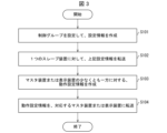
まず、図3から図6も参照して、制御グループの設定情報の設定動作について説明する。図3は、上記ネットワークシステムでの設定情報の設定動作を示すフローチャートである。図4は、上記ネットワーク機器に設定される構成リストの具体例を示す図である。図5は、上記ネットワーク機器に設定される通知先リストの具体例を示す図である。図6は、上記ネットワーク機器に設定される異常時動作設定リストの具体例を示す図である。尚、以下の動作例の説明では、図1に示した制御グループC1のスレーブ装置2Aに対して、設定情報Siを設定し、このスレーブ装置2Aをネットワーク機器2Nとする場合を例示して説明する。
§3 Operation example <Setting operation>
First, the operation of setting the setting information of the control group will be described with reference to Fig. 3 to Fig. 6. Fig. 3 is a flowchart showing the operation of setting the setting information in the network system. Fig. 4 is a diagram showing a specific example of a configuration list set in the network device. Fig. 5 is a diagram showing a specific example of a notification destination list set in the network device. Fig. 6 is a diagram showing a specific example of an abnormality operation setting list set in the network device. In the following explanation of the operation example, a case will be explained in which setting information Si is set for the
初めにステップS101で、情報処理装置3では、ユーザーの操作に基づいて、制御グループC1に対する設定情報Siの作成が行われる。この設定情報Siには、例えば、図4に示す構成リストSi1と、図5に示す通知先リストSi2と、図6に示す異常時動作設定リストSi3とが含まれている。また、この設定情報Siには、構成リストSi1に登録された他のスレーブ装置2への上記応答指示の発行周期も設定されて、含められている。 First, in step S101, the information processing device 3 creates setting information Si for the control group C1 based on a user operation. This setting information Si includes, for example, the configuration list Si1 shown in FIG. 4, the notification destination list Si2 shown in FIG. 5, and the abnormality operation setting list Si3 shown in FIG. 6. In addition, this setting information Si also includes a period for issuing the response instructions to the other slave devices 2 registered in the configuration list Si1.
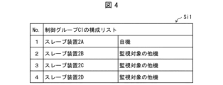
構成リストSi1は、ネットワーク機器2Nの監視対象となるグループ(例えば、制御グループC1)に含まれた他のスレーブ装置2が示されており、この構成リストSi1には、図4に示すように、制御グループC1に含まれたスレーブ装置2A、2B、2C、2Dを特定するための情報(例えば、IPアドレス)と、ネットワーク機器2Nに選定されていることを示す情報(例えば、自機)と、ネットワーク機器2Nに選定されていないことを示す情報(例えば、監視対象の他機)とがテーブル形式で記載されている。
The configuration list Si1 shows the other slave devices 2 included in the group (e.g., control group C1) that is the target of monitoring of the
通知先リストSi2には、図5に示すように、制御グループC1のいずれかのスレーブ装置2に異常が生じた時にその異常発生を通知する通知先である、例えば、マスタ装置1及び表示装置4を特定するための情報(例えば、IPアドレス)がテーブル形式で記載されている。尚、この説明以外に、通知先リストSi2に対して、他のスレーブ装置(例えば、スレーブ装置2B)2を登録する構成でもよい。
As shown in FIG. 5, the notification destination list Si2 lists, in table format, information (e.g., IP addresses) for identifying the
異常時動作設定リストSi3は、異常時にグループ停止、つまり、上記監視対象となるグループに含まれた全てのスレーブ装置2について、少なくとも一部の動作を停止させるか否かについて示されている。更に、異常時動作設定リストSi3には、ネットワーク機器2NのLED22Lを点灯させて異常報知を行うか否かが記載されている。
The abnormality operation setting list Si3 indicates whether or not to stop the group in the event of an abnormality, that is, whether or not to stop at least a portion of the operation of all slave devices 2 included in the group to be monitored. Furthermore, the abnormality operation setting list Si3 indicates whether or not to light up the
尚、スレーブ装置2の少なくとも一部の動作を停止させるとは、スレーブ装置2がその電源をオフにしてシャットダウンすることでもあってもよい。あるいは、電源はオフにしないが当該スレーブ装置2による各種制御を停止し、次の命令を待つ待機状態とすることであってもよい。 Note that stopping at least a portion of the operation of the slave device 2 may mean that the slave device 2 is shut down by turning off its power. Alternatively, it may mean that the power is not turned off but various controls by the slave device 2 are stopped and the slave device 2 is put into a standby state waiting for the next command.
次にステップS102で、情報処理装置3は、ネットワーク機器2Nに選定したスレーブ装置2Aに対して、作成した設定情報Siを転送する。これにより、スレーブ装置2Aでは、上記構成リストSi1、通知先リストSi2、及び異常時動作設定リストSi3を含んだ設定情報Siがその記憶部25に記憶される。
Next, in step S102, the information processing device 3 transfers the created setting information Si to the
次にステップS103で、情報処理装置3では、ユーザーの操作に基づいて、マスタ装置1または表示装置4の少なくとも一方に対する動作設定情報の作成が行われる。この動作設定情報は、上記監視対象となるグループに含まれたいずれかのスレーブ装置2に異常が生じたことが検出されると、上記通知先リストSi2に登録されたマスタ装置1または表示装置4の少なくとも一方での動作を指示する情報が含まれている。
Next, in step S103, the information processing device 3 creates operation setting information for at least one of the
具体的には、例えば、マスタ装置1への動作設定情報には、スレーブ装置2の異常発生時に当該マスタ装置1での制御プログラムを停止させるか否かを指示する情報を含めることができる。また、表示装置4への動作設定情報には、スレーブ装置2の異常発生時に当該表示装置4でそのスレーブ装置2の異常発生の表示を行うか否かを指示する情報を含めることができる。
Specifically, for example, the operation setting information for the
次にステップS104で、情報処理装置3は、動作設定情報を作成した、マスタ装置1または表示装置4の少なくとも一方に対し、当該動作設定情報を転送する。これにより、マスタ装置1または表示装置4の少なくとも一方では、動作設定情報が予め設定されて、スレーブ装置2の異常発生が通知されると、当該動作設定情報に従って、動作する。
Next, in step S104, the information processing device 3 transfers the operation setting information to at least one of the
<異常検出動作>
次に、図7も参照して、本実施形態のネットワーク機器2Nでの異常検出動作について具体的に説明する。図7は、上記ネットワーク機器の動作例を説明するフローチャートである。尚、以下の説明では、ネットワーク機器2Nとしてのスレーブ装置2Aでの動作を例示して説明する。
<Abnormality detection operation>
Next, the abnormality detection operation in the
初めにステップS1で、制御部23は、通信部21を通じて、構成リストSi1に登録された他のスレーブ装置2に対して、応答指示を送信する。
First, in step S1, the
ステップS2で、制御部23は、応答指示を送信した全てのスレーブ装置2から当該応答指示に対する応答を受信したか否かについて判別する。全てのスレーブ装置2から応答を受信している場合(S2でYES)、制御部23は、応答指示を送信した全てのスレーブ装置2に異常が生じていないと判断して、ステップS1に進み、それ以外の場合(S2でNO)、制御部23は、応答指示を送信したいずれかのスレーブ装置2に異常が生じていると判断して、ステップS3に進む(ステップS2)。
In step S2, the
ステップS3で、制御部23は、記憶部24に通知先リストSi2が記憶されているか否かについて判別する。通知先リストSi2が記憶されている場合(S3でYES)、ステップS4に進み、通知先リストSi2が記憶されていない場合(S3でNO)、ステップS5に進む(ステップS3)。
In step S3, the
ステップS4で、制御部23は、通信部21を通じて、記憶部24に記憶された通知先リストSi2に登録された装置に対して、スレーブ装置2に異常が生じたことを通知する。ここで通知先リストSi2に登録された装置は、マスタ装置1、表示装置4、他のスレーブ装置2であり得る。次にフローはステップS5に進む。
In step S4, the
ステップS5で、制御部23は、記憶部24に記憶されている異常時動作設定リストSi3を参照して、グループ停止設定がなされているか否かについて判別する。グループ停止設定がなされている場合(S5でYES)、ステップS6に進み、グループ停止設定がなされていない場合(S5でNO)、ステップS7に進む(ステップS5)。
In step S5, the
ステップS6で、制御部23は、通信部21を通じて、構成リストSi1に登録された全てのスレーブ装置2に対して、その少なくとも一部の動作を停止させる旨の指示を送信する。次にフローはステップS7に進む。
In step S6, the
ステップS7で、制御部23は、上記異常時動作設定リストSi3を参照して、当該ネットワーク機器2Nの異常報知部22による異常報知を実行させるが設定されているか否かについて判別する。指示が設定されている場合(S7でYES)、ステップS8に進み、指示が設定されていない場合(S7でNO)、ネットワーク機器2Nは、処理動作を終了する(ステップS7)。
In step S7, the
ステップS8で、制御部23は、異常報知部22に異常報知を実行させる。具体的には、制御部23は、所定の異常パターンで、異常報知部22のLED22Lを点灯動作させる。
In step S8, the
以上のように、本実施形態のネットワーク機器2N及びネットワークシステム100では、制御グループC1の構成リストSi1に登録されたいずれかのスレーブ装置2に異常が生じた場合に、当該構成リストSi1に含まれた全てのスレーブ装置2において、その少なくとも一部の動作を停止させることができる。
As described above, in the
この結果、本実施形態のネットワーク機器2N及びネットワークシステム100では、制御グループC1のいずれかのスレーブ装置2に異常が生じたときでも、その異常を生じたスレーブ装置2の少なくとも一部の動作と当該スレーブ装置2に連携する他のスレーブ装置2の少なくとも一部の動作、つまり、当該制御グループC1の全てのスレーブ装置2の少なくとも一部の動作を直ちに停止させることができる。
As a result, in the
従って、本実施形態のネットワーク機器2N及びネットワークシステム100では、上記従来例と異なり、例えば、一のスレーブ装置が異常発生に起因して動作を停止したときに、これに連携する他のスレーブ装置が稼働を継続することによって製造物の生産にトラブルが生じるなどの問題の発生を容易に防ぐことができる。
Therefore, unlike the conventional example described above, the
また、本実施形態では、制御グループC1内の一のスレーブ装置2をネットワーク機器2Nに設定し、当該ネットワーク機器2Nにより、制御グループC1の他のスレーブ装置2での異常発生の有無を監視しているので、例えば、生産ラインにおいて、マスタ装置1に制御されるスレーブ装置2の設置数が膨大な設置数になった場合でも、マスタ装置1での通信負荷などの処理負荷の増大やマスタ装置1の高性能化を行うことなく、当該生産ラインでのスレーブ装置2での異常発生の有無を容易に監視することができるとともに、スレーブ装置2の異常発生時にはマスタ装置1を介することなく制御グループC1の全てのスレーブ装置2の少なくとも一部の動作を迅速に停止させることができる。
In addition, in this embodiment, one slave device 2 in the control group C1 is set as a
また、本実施形態では、異常発生時に異常を通知する通知先リストSi2がネットワーク機器2Nの記憶部24に予め設定されているので、スレーブ装置2に異常が発生したときにその異常発生を通知先リストSi2に登録されたマスタ装置1や表示装置4に通知することができ、ユーザーに対して、異常の発生を早急に報知することが可能となる。
In addition, in this embodiment, a notification list Si2 for notifying an abnormality when it occurs is preset in the
また、本実施形態では、異常発生時に異常報知部22のLED22Lが異常パターンで点灯動作するので、異常が発生したときに、異常を生じたスレーブ装置2を含む制御グループC1を容易に視認させることができる。尚、上記の説明以外に、異常が生じたときに、構成リストS1iに登録された全てのスレーブ装置2において、その異常報知部のLEDを異常パターンで点灯動作させてもよい。
In addition, in this embodiment, when an abnormality occurs, the
また、上記の説明では、ネットワーク機器2Nとスレーブ装置2とを同一の構成にした場合について説明したが、本開示はこれに限定されるものではなく、これらネットワーク機器2Nとスレーブ装置2とを別個の構成としてもよい。但し、ネットワーク機器2Nとスレーブ装置2とを同一の構成にする場合の方が、制御グループでのネットワーク機器2Nの選定や変更を簡単に行える点で好ましい。
In addition, in the above explanation, the
〔ソフトウェアによる実現例〕
ネットワーク機器2Nの機能ブロック(特に、制御部23)は、集積回路(ICチップ)等に形成された論理回路(ハードウェア)によって実現してもよいし、ソフトウェアによって実現してもよい。
[Software implementation example]
The functional blocks of the
後者の場合、制御部23は、各機能を実現するソフトウェアであるプログラムの命令を実行するコンピュータを備えている。このコンピュータは、例えば1つ以上のプロセッサを備えていると共に、上記プログラムを記憶したコンピュータ読み取り可能な記録媒体を備えている。そして、上記コンピュータにおいて、上記プロセッサが上記プログラムを上記記録媒体から読み取って実行することにより、本開示の目的が達成される。
In the latter case, the
上記プロセッサとしては、例えばCPU(Central Processing Unit)を用いることができる。上記記録媒体としては、「一時的でない有形の媒体」、例えば、ROM(Read Only Memory)等の他、テープ、ディスク、カード、半導体メモリ、プログラマブルな論理回路などを用いることができる。また、上記プログラムを展開するRAM(Random Access Memory)などを更に備えていてもよい。 The processor may be, for example, a CPU (Central Processing Unit). The recording medium may be a "non-transitory tangible medium" such as a ROM (Read Only Memory), as well as a tape, a disk, a card, a semiconductor memory, or a programmable logic circuit. The device may further include a RAM (Random Access Memory) for expanding the program.
また、上記プログラムは、該プログラムを伝送可能な任意の伝送媒体(通信ネットワークや放送波等)を介して上記コンピュータに供給されてもよい。なお、本発明の一態様は、上記プログラムが電子的な伝送によって具現化された、搬送波に埋め込まれたデータ信号の形態でも実現され得る。 The program may be supplied to the computer via any transmission medium capable of transmitting the program (such as a communication network or broadcast waves). One aspect of the present invention may also be realized in the form of a data signal embedded in a carrier wave, in which the program is embodied by electronic transmission.
本開示は上述した各実施形態に限定されるものではなく、請求項に示した範囲で種々の変更が可能であり、異なる実施形態にそれぞれ開示された技術的手段を適宜組み合わせて得られる実施形態についても本開示の技術的範囲に含まれる。 This disclosure is not limited to the above-described embodiments, and various modifications are possible within the scope of the claims. Embodiments obtained by appropriately combining the technical means disclosed in different embodiments are also included in the technical scope of this disclosure.
1 マスタ装置
2 スレーブ装置
2N ネットワーク機器
21 通信部
22 異常報知部
22L LED(発光素子)
23 制御部
24 記憶部
100 ネットワークシステム
1 Master device 2
23
Claims (6)
他の前記スレーブ装置との間でデータの送受信を行う通信部と、
当該ネットワーク機器と少なくとも1つの他の前記スレーブ装置とを含んだグループの構成リストを予め記憶する記憶部と、
当該ネットワーク機器の各部を制御する制御部と、を備え、
前記制御部は、
前記通信部を通じて、前記構成リストに登録された他の前記スレーブ装置に対して、応答指示を送信し、
前記応答指示に対する応答をしない他の前記スレーブ装置がある場合に、前記通信部を通じて、前記構成リストに登録された他の前記スレーブ装置に対して、その少なくとも一部の動作を停止させる旨の指示を送信するとともに、当該ネットワーク機器の少なくとも一部の動作を停止させる、ネットワーク機器。 A network device which is a slave device used in a network system in which a master device and a plurality of slave devices controlled by the master device are connected, comprising:
a communication unit for transmitting and receiving data between the slave device and the other slave device;
a storage unit that stores in advance a configuration list of a group including the network device and at least one of the other slave devices;
A control unit that controls each unit of the network device,
The control unit is
Transmitting a response instruction to the other slave devices registered in the configuration list via the communication unit;
a network device that, when there is another slave device that does not respond to the response instruction, transmits an instruction to the other slave device registered in the configuration list via the communication unit to stop at least a portion of its operation, and stops at least a portion of the operation of the network device.
前記制御部は、
前記応答指示に対する応答をしない他の前記スレーブ装置がある場合に、前記異常報知部に異常報知を実行させる、請求項1に記載のネットワーク機器。 An abnormality notification unit that executes an abnormality notification is further provided,
The control unit is
The network device according to claim 1 , wherein, when there is another slave device that does not respond to the response instruction, the abnormality notification section is caused to execute an abnormality notification.
前記制御部は、
前記応答指示に対する応答をしない他の前記スレーブ装置がある場合に、前記通知先リストに登録された前記マスタ装置または前記通知先リストに登録された他の前記スレーブ装置に対して、異常が生じた旨の通知を送信する、請求項1から3のいずれか1項に記載のネットワーク機器。 the storage unit prestores a notification destination list in which at least one of the master device and the other slave device is registered;
The control unit is
4. The network device according to claim 1, further comprising: a network device configured to transmit, when there is another slave device that does not respond to the response instruction, a notification that an abnormality has occurred to the master device registered in the notification destination list or to the other slave device registered in the notification destination list .
前記制御部は、
前記応答指示に対する応答をしない他の前記スレーブ装置がある場合に、前記通知先リストに登録された前記表示装置に対して、異常が生じた旨の通知を送信する、請求項4に記載のネットワーク機器。 A display device that displays the occurrence of an abnormality is further registered in the notification destination list,
The control unit is
5. The network device according to claim 4, wherein if there is another slave device that does not respond to the response instruction, a notification that an abnormality has occurred is transmitted to the display device registered in the notification destination list.
請求項1から5のいずれか1項に記載のネットワーク機器が、前記スレーブ装置として接続されている、ネットワークシステム。 A network system in which a master device and a plurality of slave devices controlled by the master device are connected,
A network system, in which the network device according to claim 1 is connected as the slave device.
Priority Applications (2)
| Application Number | Priority Date | Filing Date | Title |
|---|---|---|---|
| JP2021037851A JP7608880B2 (en) | 2021-03-09 | 2021-03-09 | Network equipment and network systems |
| PCT/JP2021/046660 WO2022190504A1 (en) | 2021-03-09 | 2021-12-17 | Network equipment and network system |
Applications Claiming Priority (1)
| Application Number | Priority Date | Filing Date | Title |
|---|---|---|---|
| JP2021037851A JP7608880B2 (en) | 2021-03-09 | 2021-03-09 | Network equipment and network systems |
Publications (2)
| Publication Number | Publication Date |
|---|---|
| JP2022138061A JP2022138061A (en) | 2022-09-22 |
| JP7608880B2 true JP7608880B2 (en) | 2025-01-07 |
Family
ID=83227897
Family Applications (1)
| Application Number | Title | Priority Date | Filing Date |
|---|---|---|---|
| JP2021037851A Active JP7608880B2 (en) | 2021-03-09 | 2021-03-09 | Network equipment and network systems |
Country Status (2)
| Country | Link |
|---|---|
| JP (1) | JP7608880B2 (en) |
| WO (1) | WO2022190504A1 (en) |
Citations (3)
| Publication number | Priority date | Publication date | Assignee | Title |
|---|---|---|---|---|
| WO2020031990A1 (en) | 2018-08-06 | 2020-02-13 | エドワーズ株式会社 | Detoxifying system, detoxifying device, and system control device |
| JP2020187486A (en) | 2019-05-13 | 2020-11-19 | オムロン株式会社 | Control apparatus |
| JP2020190952A (en) | 2019-05-22 | 2020-11-26 | オムロン株式会社 | Control devices, network systems, network system control methods and control programs |
-
2021
- 2021-03-09 JP JP2021037851A patent/JP7608880B2/en active Active
- 2021-12-17 WO PCT/JP2021/046660 patent/WO2022190504A1/en not_active Ceased
Patent Citations (3)
| Publication number | Priority date | Publication date | Assignee | Title |
|---|---|---|---|---|
| WO2020031990A1 (en) | 2018-08-06 | 2020-02-13 | エドワーズ株式会社 | Detoxifying system, detoxifying device, and system control device |
| JP2020187486A (en) | 2019-05-13 | 2020-11-19 | オムロン株式会社 | Control apparatus |
| JP2020190952A (en) | 2019-05-22 | 2020-11-26 | オムロン株式会社 | Control devices, network systems, network system control methods and control programs |
Also Published As
| Publication number | Publication date |
|---|---|
| WO2022190504A1 (en) | 2022-09-15 |
| JP2022138061A (en) | 2022-09-22 |
Similar Documents
| Publication | Publication Date | Title |
|---|---|---|
| JP6477554B2 (en) | RELAY DEVICE, RELAY DEVICE CONTROL METHOD, CONTROL PROGRAM, AND RECORDING MEDIUM | |
| US20090204695A1 (en) | Automation network comprising network components that produce status messages | |
| JP7476579B2 (en) | Cable abnormality determination system, slave device, and cable abnormality determination method | |
| US11740604B2 (en) | Control device | |
| JP7608880B2 (en) | Network equipment and network systems | |
| JP7604953B2 (en) | Network equipment and network systems | |
| WO2015132938A1 (en) | Safety control system and safety control appliance | |
| JP2012198841A (en) | Field network system | |
| CN115104289B (en) | Terminal monitoring device | |
| JP2016156768A (en) | Photoelectronic sensor | |
| TW201917504A (en) | Output unit, input unit, and input-output system | |
| KR101294308B1 (en) | Facilities control system and operating method of the system | |
| TW201701090A (en) | Production line system including a display having a priority among multiple devices to display errors | |
| WO2022107347A1 (en) | Slave device, network system, method and program for controlling slave device | |
| JP7297688B2 (en) | Monitoring equipment, switchboards and monitoring systems | |
| JP2019134350A (en) | Management system | |
| JP2005165397A (en) | Equipment for input devices | |
| JP2003287267A (en) | Fan filter unit monitoring and control system | |
| JP2023134106A (en) | Terminal control device, terminal control device control method, terminal control program, slave device, and master device | |
| JP2024053927A (en) | Lighting Control System | |
| JP6406688B2 (en) | Centralized monitoring system, centralized monitoring device therefor, and terminal monitoring device | |
| JP2020047490A (en) | Control unit and unit system | |
| JP2006074142A (en) | Nurse call system | |
| JPH0711079U (en) | Supervisory control device | |
| KR20050034411A (en) | Appliance used for both master device and slave device and its operating method |
Legal Events
| Date | Code | Title | Description |
|---|---|---|---|
| A621 | Written request for application examination |
Free format text: JAPANESE INTERMEDIATE CODE: A621 Effective date: 20240116 |
|
| A131 | Notification of reasons for refusal |
Free format text: JAPANESE INTERMEDIATE CODE: A131 Effective date: 20241029 |
|
| A521 | Request for written amendment filed |
Free format text: JAPANESE INTERMEDIATE CODE: A523 Effective date: 20241106 |
|
| TRDD | Decision of grant or rejection written | ||
| A01 | Written decision to grant a patent or to grant a registration (utility model) |
Free format text: JAPANESE INTERMEDIATE CODE: A01 Effective date: 20241119 |
|
| A61 | First payment of annual fees (during grant procedure) |
Free format text: JAPANESE INTERMEDIATE CODE: A61 Effective date: 20241202 |
|
| R150 | Certificate of patent or registration of utility model |
Ref document number: 7608880 Country of ref document: JP Free format text: JAPANESE INTERMEDIATE CODE: R150 |