JP7608850B2 - Electronic device, insole-type electronic device and monitoring system - Google Patents
Electronic device, insole-type electronic device and monitoring system Download PDFInfo
- Publication number
- JP7608850B2 JP7608850B2 JP2021014235A JP2021014235A JP7608850B2 JP 7608850 B2 JP7608850 B2 JP 7608850B2 JP 2021014235 A JP2021014235 A JP 2021014235A JP 2021014235 A JP2021014235 A JP 2021014235A JP 7608850 B2 JP7608850 B2 JP 7608850B2
- Authority
- JP
- Japan
- Prior art keywords
- electronic device
- insole
- housing
- heel
- board
- Prior art date
- Legal status (The legal status is an assumption and is not a legal conclusion. Google has not performed a legal analysis and makes no representation as to the accuracy of the status listed.)
- Active
Links
- 238000012544 monitoring process Methods 0.000 title description 4
- 239000000758 substrate Substances 0.000 claims description 17
- 239000000463 material Substances 0.000 claims description 15
- 230000001681 protective effect Effects 0.000 claims description 14
- 238000003780 insertion Methods 0.000 claims description 13
- 230000037431 insertion Effects 0.000 claims description 13
- 239000000945 filler Substances 0.000 claims description 7
- 238000007789 sealing Methods 0.000 claims description 7
- 238000012806 monitoring device Methods 0.000 claims description 5
- 238000005299 abrasion Methods 0.000 claims description 4
- 239000003795 chemical substances by application Substances 0.000 claims description 4
- 238000004891 communication Methods 0.000 claims description 4
- 239000000314 lubricant Substances 0.000 claims description 3
- 238000000034 method Methods 0.000 description 12
- 238000004519 manufacturing process Methods 0.000 description 11
- 238000003860 storage Methods 0.000 description 11
- 239000000565 sealant Substances 0.000 description 5
- 230000037396 body weight Effects 0.000 description 3
- 229920001971 elastomer Polymers 0.000 description 3
- 238000005516 engineering process Methods 0.000 description 3
- 238000005259 measurement Methods 0.000 description 3
- 230000035939 shock Effects 0.000 description 3
- 206010012289 Dementia Diseases 0.000 description 2
- 239000004743 Polypropylene Substances 0.000 description 2
- 238000010521 absorption reaction Methods 0.000 description 2
- 230000006378 damage Effects 0.000 description 2
- 238000004332 deodorization Methods 0.000 description 2
- 230000000694 effects Effects 0.000 description 2
- 239000004417 polycarbonate Substances 0.000 description 2
- -1 polyethylene terephthalate Polymers 0.000 description 2
- 229920000139 polyethylene terephthalate Polymers 0.000 description 2
- 239000005020 polyethylene terephthalate Substances 0.000 description 2
- 239000004800 polyvinyl chloride Substances 0.000 description 2
- 229920000915 polyvinyl chloride Polymers 0.000 description 2
- 238000012360 testing method Methods 0.000 description 2
- 229920006311 Urethane elastomer Polymers 0.000 description 1
- 239000011358 absorbing material Substances 0.000 description 1
- 239000000853 adhesive Substances 0.000 description 1
- 230000001070 adhesive effect Effects 0.000 description 1
- 239000002390 adhesive tape Substances 0.000 description 1
- 230000005540 biological transmission Effects 0.000 description 1
- 238000006243 chemical reaction Methods 0.000 description 1
- 238000010276 construction Methods 0.000 description 1
- 238000013461 design Methods 0.000 description 1
- 238000001514 detection method Methods 0.000 description 1
- 239000000806 elastomer Substances 0.000 description 1
- 230000004907 flux Effects 0.000 description 1
- 238000005187 foaming Methods 0.000 description 1
- 239000011888 foil Substances 0.000 description 1
- 230000002452 interceptive effect Effects 0.000 description 1
- 239000007788 liquid Substances 0.000 description 1
- 229920000515 polycarbonate Polymers 0.000 description 1
- 229920001155 polypropylene Polymers 0.000 description 1
- 229920001296 polysiloxane Polymers 0.000 description 1
- 229920002635 polyurethane Polymers 0.000 description 1
- 239000004814 polyurethane Substances 0.000 description 1
- 238000004080 punching Methods 0.000 description 1
- 239000011347 resin Substances 0.000 description 1
- 229920005989 resin Polymers 0.000 description 1
- 239000011359 shock absorbing material Substances 0.000 description 1
- 229920002545 silicone oil Polymers 0.000 description 1
- 229920002379 silicone rubber Polymers 0.000 description 1
- 239000004945 silicone rubber Substances 0.000 description 1
- 229910000859 α-Fe Inorganic materials 0.000 description 1
Images


Landscapes
- Footwear And Its Accessory, Manufacturing Method And Apparatuses (AREA)
Description
本発明は、電子機器および見守りシステムに関する。 The present invention relates to electronic devices and monitoring systems.
近年、身体に電子機器を装着して、生体情報や位置情報などを取得することが盛んになっている。電子機器の装着方法の一つに、靴に電子機器を組み込む方法がある。この方法では、ユーザーの行動を妨げないことや、履くことによる不快感を生じさせないことが求められる。 In recent years, it has become common to wear electronic devices on the body to obtain biometric and location information. One method for wearing electronic devices is to incorporate them into shoes. With this method, it is necessary to ensure that the electronic devices do not interfere with the user's movements or cause discomfort when worn.
この要求に応える技術が、例えば、特許文献1に開示されている。この技術では、靴の中底の面内、または中敷きの中底側の面に、ハウジング(空洞)を設け、そのハウジングの中に、電子モジュールを収納している。この構成とすることで、装着による不快感が生じないようにしている。さらに、電子モジュールとハウジングの隙間を、衝撃吸収材で埋めることにより、一層、不快感を生じ難くする方法も開示されている。 A technology that meets this demand is disclosed, for example, in Patent Document 1. In this technology, a housing (cavity) is provided within the surface of the midsole of the shoe, or on the surface of the midsole side of the insole, and an electronic module is stored inside the housing. This configuration prevents discomfort caused by wearing the shoe. Furthermore, a method is disclosed in which the gap between the electronic module and the housing is filled with a shock absorbing material to further reduce discomfort.
また特許文献2にも、靴のかかと(アウトソールのヒール部分)内に室を設け、この室内に、GPS(Global Positioning System)受信機や通信機器を収容することで、位置探索用携帯機器を構成する方法が開示されている。靴のかかとに電子機器を収容することで、ユーザーの行動を妨げることなく、ユーザーの位置情報を取得できるようにしている。 Patent Document 2 also discloses a method of constructing a portable device for location search by providing a chamber in the heel of a shoe (the heel part of the outsole) and housing a GPS (Global Positioning System) receiver and communication device in this chamber. By housing the electronic device in the heel of the shoe, it is possible to obtain the user's location information without interfering with the user's movements.
しかしながら、特許文献1の技術では、足裏と靴底で挟まれる位置に電子モジュールがあるため、歩行や走行で発生する衝撃と荷重で、電子モジュールがダメージを受け、信頼性に懸念が生じるという問題点があった。特許文献1では、ハウジング内に衝撃吸収材を充填することで、衝撃を和らげられる方法も示されているが、衝撃を完全に吸収することはできないため、十分ではなかった。また、衝撃は軽減できても荷重が掛かるという問題があった。 However, with the technology in Patent Document 1, the electronic module is located in a position sandwiched between the sole of the foot and the shoe insole, so the electronic module can be damaged by the impact and load generated by walking or running, raising concerns about reliability. Patent Document 1 also shows a method of cushioning the impact by filling the housing with an impact absorbing material, but this is not sufficient as it cannot completely absorb the impact. Also, even if the impact can be reduced, there is a problem in that a load is still applied.
また特許文献2にも同様な問題があった。特に、靴のヒール部分は、足裏で最も荷重の大きい場所であるため、電子機器が受けるダメージも大きくなっていた。 Patent Document 2 also had a similar problem. In particular, the heel of the shoe is the part of the sole that bears the greatest load, so electronic devices are more likely to sustain damage.
本発明は、上記の問題に鑑みてなされたものであり、電子モジュールが歩行や走行による衝撃や荷重を受けにくい中敷き型電子機器を提供することを目的としている。 The present invention was made in consideration of the above problems, and aims to provide an insole-type electronic device in which the electronic module is less susceptible to shocks and loads caused by walking or running.
上記の課題を解決するため、本発明の電子機器は、靴の内側踵部に沿って立掛けて足の踵後方を包み込む馬蹄型の基体と、基体に搭載された電子基板とを有する。電子機器は靴の内側踵部に沿って立掛けた状態で配置されるため、電子機器が備える電子基板が、足裏から荷重や衝撃を受けることがない。その結果、電子基板をこれらの荷重や衝撃から保護することができる。 In order to solve the above problems, the electronic device of the present invention has a horseshoe-shaped base that stands along the inner heel of the shoe and wraps around the back of the heel of the foot, and an electronic board mounted on the base. Because the electronic device is placed in a standing state along the inner heel of the shoe, the electronic board equipped in the electronic device is not subjected to loads or impacts from the sole of the foot. As a result, the electronic board can be protected from these loads and impacts.
本発明の効果は、電子基板が歩行や走行による衝撃や荷重を受けにくい電子機器を提供できることである。 The effect of the present invention is to provide electronic equipment whose electronic board is less susceptible to shocks and loads caused by walking or running.
以下、図面を参照しながら、本発明の実施形態を詳細に説明する。但し、以下に述べる実施形態には、本発明を実施するために技術的に好ましい限定がされているが、発明の範囲を以下に限定するものではない。なお各図面の同様の構成要素には同じ番号を付し、説明を省略する場合がある。 Below, an embodiment of the present invention will be described in detail with reference to the drawings. However, the embodiment described below has limitations that are technically preferable for implementing the present invention, but does not limit the scope of the invention to the following. Note that similar components in each drawing are given the same numbers, and descriptions may be omitted.
(第1の実施形態)
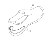
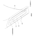
図1は、第1の実施形態の電子機器10を示す斜視図である。電子機器10は、靴の内側踵部に沿って立掛けて足の踵後方を包み込む馬蹄型の基体1と、基体1に搭載された電子基板2とを有する。
(First embodiment)
1 is a perspective view showing an
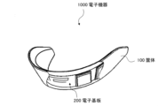
図2は、電子機器10を靴内に設置した状態を示す透視図である。電子機器10は靴20の内側踵部に沿って立掛けた状態で配置される。このため、電子機器10が備える電子基板2が、足裏から荷重や衝撃を受けることがない。その結果、電子基板2をこれらの荷重や衝撃から保護することができる。
Figure 2 is a perspective view showing the
以上説明したように、本実施形態によれば、電子基板が歩行や走行による衝撃や荷重を受けにくい電子機器を提供することができる。 As described above, this embodiment can provide an electronic device whose electronic board is less susceptible to shocks and loads caused by walking or running.
(第2の実施形態)
図3は、第2の実施形態の電子機器1000を示す部分透視斜視図である。電子機器1000は、ヒールカップ型の筐体100と、筐体100に格納された電子基板200とを有する。電子基板200は、筐体100に内蔵され、外界と隔離された状態にある。ここで、ヒールカップとは、靴を履いた際に、足の踵後方に配置され、靴の内側踵部に沿って立掛けて配置され、足の踵の後方の側面を包み込む形の構造体を指す。例えば、図3に示すように、上から見ると馬蹄形となる形状とすることができる。そして、本実施形態では、ヒールカップは、踵の側方を覆い、踵の足裏に当たる部分は含まないものとする。
Second Embodiment
FIG. 3 is a partial perspective view showing an
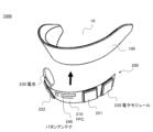
図4は本実施形態の電子機器1000のヒールカップ型の筐体100と、筐体100に格納される電子基板200とを分解した斜視図である。ヒールカップ型の電子機器1000は、靴を履いた際に、足の踵後方に配置され、靴の内側踵部に沿って立掛けて配置される。筐体100は、足の踵後方を包み込む馬蹄型、すなわちヒールカップ型である。電子基板200は、一部に可撓性を有し、筐体100の馬蹄型に沿うように湾曲形状に曲げることが可能である。
Figure 4 is an exploded perspective view of the heel
筐体100は、柔軟な素材でできており、足の踵や靴の踵部形状に沿って変形が可能である。例えばシリコーンゴムなどを用いることができる。
The
電子基板200は、例えば、可撓性を有するFPC(フレキシブルプリント基板)210と、可撓性を有しないモジュール基板と、電池230とを有する。また、例えば、FPC210上には、配線パタンで送受信用のパタンアンテナ240を形成することができる。図4の例では、モジュール基板220,221,222をFPC210上に実装している。モジュール基板220、221、222は、例えば、通信モジュール、位置検知モジュール、電源モジュール、マイコンなどとすることができる。これらのモジュール基板は、必要な機能を組み合わせてFPC160上に実装すればよい。モジュール基板の実装では、実装部の接続箇所を可能な限り小エリアに集約させて接続することが望ましい。このようにすることで、FPC160の可撓域を最大化することができ、より低応力で湾曲形状に沿わせやすくなる。すなわち、筐体と共に足の踵や靴の踵部形状に沿って変形が可能となる。
The
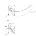
図5は、本実施形態の電子機器1000の断面を説明する斜視図である。図6は、図5における部分断面Aの拡大図である。筐体100は、電子基板200を格納する基板格納領域110を有し、一方に開口部を有する袋状である。筐体100に設けられた開口部は、電子基板200を筐体100内に挿入するための基板挿入口120である。基板挿入口120は、基板格納領域110の幅より狭いスリット状である。電子基板200は基板挿入口120を押し広げて挿入され、馬蹄型に沿うように湾曲した状態で筐体に格納されている。
Figure 5 is a perspective view illustrating a cross section of
なお、上記の説明では、筐体100に電子基板200が内蔵される構成を例にとって行ったが、電子基板200を筐体100の側面に貼付する構成や、その構成に加えて電子基板200を覆う保護シートを設ける構成などとすることも可能である。また筐体100に直接電子回路を形成することや、電子部品を搭載することができる場合は、電子基板200が筐体100と一体であっても良い。
In the above description, the
(具体例)
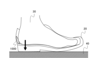
図7は、本実施形態のヒールカップ型の電子機器1000を設置した靴20を人が履いて、床40の上に立っている、あるいは歩行している様子を示す断面図である。直立した状態では、靴20を履いた人の体重は、足30と床40に挟まれる靴の踵の足裏の部分に加わる。すなわち、この荷重は、図7に矢印で示すように、足裏から鉛直方向に加わる。これに対し、踵の側面に配置されているヒールカップ型の電子機器1000には、ほとんど荷重が加わらない。体重の異なる数名にヒールカップ箇所に荷重センサを入れた靴を試着した試験では、いずれの被験者にあっても1kgf前後の測定値であった。
(Specific example)
7 is a cross-sectional view showing a state where a person is wearing a
図8は、本実施形態のヒールカップ型の電子機器1000を設置した靴20を人が履いて、走行または歩行している様子を示す断面図である。歩行または走行時にあっても体重は、図8に矢印で示す踏み込む方向に加わるため、やはりヒールカップ型の電子機器1000への荷重は、ほぼ体重に依存しない。測定試験においても同様に、ほとんど荷重が変わらないことを確認した。
Figure 8 is a cross-sectional view showing a person running or walking while wearing a
上記の具体例から、ヒールカップ箇所はデバイスを配置する場所として適していると言える。また、受ける荷重が低いということは、逆に装着者への反力が小さいということである、故に、装着者が感じる違和感も小さいと言える。また、体重の大部分を受ける足下に電子機器などの異物がないため靴本来の履き心地を損ねるといった影響も軽減できる。また、取り外して他の靴に容易に設置が可能であるため、装着者の好みに合った靴を選ぶことが可能である。 From the above specific examples, it can be said that the heel cup area is a suitable place to place the device. Furthermore, the low load means that the reaction force on the wearer is small, and therefore the discomfort felt by the wearer is small. Furthermore, since there are no foreign objects such as electronic devices under the feet, which bear the majority of the wearer's weight, the effects of impairing the inherent comfort of the shoe can be reduced. Furthermore, since the device can be easily removed and installed in other shoes, the wearer can choose shoes that suit their preferences.
(第3の実施形態)
図9は、本実施形態のヒールカップ型の電子機器2000を示す斜視図である。電子機器2000は、筐体2100と、筐体2100に格納された電子基板(図示せず)とを有する。筐体2100は、踵の側方を覆い、踵の足裏に当たる部分は含まないヒールカップ型の形状である。筐体2100は、電子基板を挿入するための基板挿入口2110をヒールカップの上面部分に有している。なお、上面とは、電子機器2000を靴の踵部分に配置したときに、上側となる面のことである。
Third Embodiment
9 is a perspective view showing a heel cup type
電子機器2000の製造に当たっては、まず、筐体2100の基板挿入口2110から、電子基板を筐体2100に挿入する。この時、筐体2100の湾曲形状に合わせて、電子基板を撓らせる。電子基板を筐体2100の所定の位置に挿入出来たら、基板挿入口2110をシーリング剤で閉塞して電子基板を封止する。シーリング剤の供給は、例えば、図9に示すように、基板挿入口2110にディスペンスノズル3000を差し込み、矢印で示すように、基板挿入口2110に沿って、ディスペンスノズル3000を移動させることによって行うことができる。次に、充填したシーリング剤を硬化させて封止する。電子基板を筐体2100とシーリング剤で封止することにより、電子機器2000に防水/防塵機能をもたせることができる。
When manufacturing the
次に、電子機器2000の封止構造の具体例について説明する。図10は、その一例を示す断面図である。この例では、筐体2100と電子基板2200の間に保護部材2300が介在している。保護部材2300は、例えば、絶縁性、耐摩耗性を有する高強度フィルムである。具体的には、例えば、高延伸PET(ポリエチレンテレフタレート)フィルムなどである。このような構成とすることで、ヒールカップ型の電子機器2000が外力により変形した際に、筐体2100と電子基板2200が直接擦れ合うことがなく、双方が円滑に自由にずれることができる低応力構造となる。そして、低応力構造である故に曲がりやすく、曲がりやすい故に電子基板2200に生じる応力が小さい。したがって、上記の構成を採用することにより、電子基板2200を応力による破壊から守ることができる。また、こうしたフィルムを複数枚重ねて介在させることで、さらに構成材が円滑に自由にずれることができ、より低応力な構造にすることができる。また、電子基板2200と保護部材2300を挿入した後に、基板挿入口2110を、シーリング剤3100で封止している。
Next, a specific example of the sealing structure of the
図11は、基板格納領域2120に充填剤3200を満たした例である。図10の例と同様に、筐体2100と電子基板2200が直接擦れ合うことがなく、双方が円滑に自由にずれることができる低応力構造を実現している。充填剤3200には、例えば、不活性液体や低硬度ゲル材などを用いればよい。具体的には、例えば、シリコーンオイル、シリコーンゲルなどを用いることができる。充填剤3200が基板格納領域2120を満たすことで。筐体2100を透過してきた湿分が筐体2100の中で結露することなく、靴内という過酷な環境であっても動作信頼性を高めることができる。
Figure 11 shows an example in which the substrate storage area 2120 is filled with filler 3200. As with the example of Figure 10, the
以上説明したように、本実施形態によれば、信頼性に優れたヒールカップ型の電子機器を構成することができる。 As described above, this embodiment makes it possible to construct a highly reliable heel cup type electronic device.
(第4の実施形態)
第1から第3の実施形態のヒールカップ型の電子機器とインソール(靴の中敷き)とを組み合わせて、インソール型の電子機器を構成することができる。図12は、ヒールカップ型の電子機器2000をインソール4000と接合したインソール型電子機器5000を示す斜視図である。インソール型電子機器5000は、ヒールカップ型の電子機器2000が靴の踵部内側面に嵌るよう配置される。そのために、通常形状のインソールからヒールカップ部分を除去した形状のインソール4000に、ヒールカップ型の電子機器2000を嵌合させ接合している。こうすることで、ヒールカップ型の電子機器2000を靴内で安定させることができる。また、快適性/疲労軽減/消臭/吸湿などインソール自身の機能に影響を与えることなく、電子機器の機能を付与することが可能となる。
(Fourth embodiment)
An insole type electronic device can be configured by combining the heel cup type electronic device of the first to third embodiments with an insole (shoe insole). FIG. 12 is a perspective view showing an insole type electronic device 5000 in which the heel cup type
なお、インソール4000の一部をくり抜き、追加機能部品を設置することも可能である。例えば、土踏まず下は足裏の中でも最も荷重を受けにくい部分であり、電池や充電アンテナなどを実装することができる。
It is also possible to hollow out a portion of the
こうして得られるヒールカップ型の電子機器2000またはインソール型電子機器5000を用いて、位置監視を行うことも可能である。例えば、ヒールカップ型の電子機器2000に、位置情報を取得する機能と、取得した位置情報を送信する機能を実装する。そして、監視センター等に、その位置情報を受信する位置監視装置を設けることで、例えば、認知症徘徊患者や広域作業者などの位置情報を監視することができる。本実施形態のインソール型電子機器5000の場合、体重の大部分を受ける足下に電子機器などの異物がないため、電子機器を装着した時の違和感が軽減されている。このため、例えば、認知症徘徊患者や広域作業者など位置管理が必要な対象者が、電子機器の持ち運びを意識することのない見守りシステムを提供できる。
It is also possible to perform location monitoring using the heel cup type
(第5の実施形態)
本実施形態では、第4の実施形態の構成を基本とし、インソールの一部に凹部形成し、この凹部に部品を設置する構成の例について説明する。インソールの中で部品を設置するのに好適な場所としては、例えば土踏まず部分と、踵部分が挙げられる。足の土踏まずの下は、足裏の中でも最も荷重を受けにくい部分である。また、足の踵の下は歩行時に撓まない部分にあたるため、インソールの踵部分は構造体を格納しても、ユーザーの違和感が生じ難い箇所であると言える。このため、上記の場所には、比較的体積の大きい大容量の電池や充電用の無線受電機能などを実装すると都合が良い。
Fifth Embodiment
In this embodiment, based on the configuration of the fourth embodiment, an example of a configuration in which a recess is formed in a part of the insole and a part is installed in this recess will be described. Suitable locations for installing parts in the insole include, for example, the arch and heel. The area under the arch of the foot is the part of the sole that receives the least load. In addition, since the area under the heel of the foot is the part that does not bend when walking, the heel of the insole is a location where the user is unlikely to feel uncomfortable even if a structure is stored therein. For this reason, it is convenient to implement a relatively large-volume, large-capacity battery or a wireless power receiving function for charging in the above locations.
図13は、図12のインソール型電子機器5000と同じ基本構成で、インソール4100をくり抜いた収納スペースを設けて、電子部品を収納したインソール型電子機器5100の一例を示す斜視図である。ここでは、電子部品として電池ユニット6100と、無線受電モジュール6200と、接続ケーブル6300とを収納する構成を例示している。また、図12のインソール型電子機器5000と同様に、ヒールカップ型の電子機器2500を配置している。さらに、インソール4100の踵部分の下側には、ベースプレート4200を配置している。上記のように、インソール4100に収納スペースを設けて電子部品を配置することにより、インソール4100の表面から突出する部分を作らずに電子部品が配置できる。突出部がないため、ユーザーは、インソール型電子機器4100を快適に使用することができる。
13 is a perspective view showing an example of an insole-type
図14はインソール型電子機器5100を機能部品毎に分解した分解斜視図である。インソール4100は、例えば、可撓性とクッション性を有するポリウレタンなどのエラストマ、ゴム、またはそれらを発砲させて形成したスポンジ材からなる足形の板状体とすることができる。インソール4100には、土踏まず部分に電池ユニット6100を収納する収納スペース4110が設けられ、踵部分には無線受電モジュール6200を収納する収納スペース4120が設けられている。また、両者の間には接続ケーブル6300を収納する連結溝4130が設けられている。
Figure 14 is an exploded perspective view of the insole-type
踵部分を補強するベースプレート4200は、例えば、靭性のある樹脂素材で形成され板状体で、その厚みは例えば0.5mm~1mm程度とすることができる。ベースプレート4200は、柔軟に撓むことができる。ベースプレート4200の土踏まず周辺から踵にかけての外縁部には、上方にせり上がった壁部4220が設けられている。ベースプレートの素材には、PP(ポリプロピレン)、PC(ポリカーボネイト)やウレタン系エラストマ、PVC(ポリ塩化ビニル)など種々選択することができる
図15は、インソール型電子機器5100を、足を乗せる面から描いた平面図である。また図16は、図15のA-A´における断面図である。電池ユニット6100は、電池6110と、電源系の回路およびインターフェースコネクタなどを搭載した電子回路6120とを、まとめて一つの筐体6130に格納したものである。電池ユニット6100は、例えば、ボタン形2次電池とその保護回路、充電回路、データ計測用のIMUおよび電子機器2000への電源として、電圧を降圧または昇圧させる制御回路を備える。ここでIMUは、Inertial Measurement Unit(慣性計測センサ)の略である。しかしながら、実装する機能は、上記に限られるものではない。
The
無線受電モジュール6200は、電池を充電するための電力を供給する機能を有している。無線受電モジュール6200は、アンテナコイル6210と、制御回路6220と、フェライト板6230と、これらを収納する筐体6230から構成されている。アンテナコイル6210は、外部にある無線送電モジュールから電力を受電する。制御回路6220は、受電した電力を整流し、安定化させ、電圧を降圧または昇圧させる。充電を行う際は、受電アンテナコイル6210を、外部の無線送電モジュール(図示せず)の送電アンテナコイルと対向させる。そして、送電アンテナコイルに交流電流を流し、磁束を発生、変化させて、受電アンテナコイル6210に起電力を発生させる。なお、制御回路6220の機能は、電池ユニット6100内の電子回路6120に集約してもよい。
The wireless
ベースプレート4200は、インソール4100の踵部分と、ヒールカップ型の電子機器2500を保持しつつ、これらと接合されている。ここで、電子機器2500の底部は、ベースプレート4200の壁部4220に沿って位置決めされている。また、インソール4100の踵部分の端部は、電子機器2500の内側と、ベースプレート4200の外形に合わせて位置決めされている。
The
上記の構成とするのは、薄くてコシのないインソール4100の側面にヒールカップ型の電子機器2500を取り付けるのが困難なためである。上記のように、ベースプレート4200を基準に各機能を一括して載せて固定することで容易に組み立てることができる。固定方法には、例えば、接着剤や両面粘着テープを用いることができる。なお、図14、16の例では、電池ユニット6100を、ベースプレート4200に設けられた貫通穴4210に嵌め込む形としているが、貫通穴4210をなくして、ベースプレート4200上で保持してもよい。
The above configuration is used because it is difficult to attach the heel cup type
図17は、図16のインソール型電子機器5100の変形例を示す断面図である。この変形例では、ベースプレート4200に、電池ユニット6100の上面を覆う凸部4201と、無線受電モジュール6200の上面を覆う凸部4202を設けている。そして、凸部4201と筐体6131とで電池ユニット6100を囲み、凸部4202と筐体6231とで無線受電モジュール6200を囲んでいる。上記の構成とすることで、インソール4100にベースプレート4200を積載/固定する際の位置決めが容易になる。
Figure 17 is a cross-sectional view showing a modified example of the insole-type
なお、上記の説明では、収納スペース4110、4120に収納する電子部品が電池ユニット6100と無線受電モジュール6200である例を用いたが、電子部品はこれらに限定されず、任意のものを用いることができる。
In the above description, the electronic components stored in the storage spaces 4110 and 4120 are the
(第6の実施形態)
本実施形態では、第5の実施形態のインソール型電子機器5100の上方に、第2のインソール4101を重ねたインソール型電子機器5101について説明する。図18は、インソール型電子機器5101を示す分解斜視図である。また、図19は、インソール4100と第2のインソール4101を重ねて、インソール型電子機器5101を組み立てた状態を示す斜視図である。
Sixth Embodiment
In this embodiment, an insole-type electronic device 5101 will be described in which a
上記の構成では、第2のインソール4101を、インソール型電子機器5101に付加したい電子デバイスの機能と無関係に選ぶことができる。このため、インソールとして必要な、快適性/疲労軽減/消臭/吸湿などの機能を第2のインソールで担保して、個々人の嗜好に応じたインソール型電子機器5101を構成することができる。ゆえに、インソール型電子機器5100のインソール4100には、快適性などを求めなくて良くなり、素材の選択肢を幅広くもつことができる。例えば、柔軟性については、デュロA30~70°程度の硬度を有していればよい。また形状についても、平板形状であればよく、土踏まず箇所を盛り上げるなどの複雑な立体形状を設計する必要もない。このため、インソール4100は、例えば、スポンジ材やゴム材の平板を抜き型(ビク型、トムソン型など)で打ち抜けば、容易に制作することができる。また、3Dプリンタのラバーライク材を用いて成形すれば、全く金型も必要なく、簡便に少量生産を行うことができる。したがって、高価な金型を起こす必要がなく、また、使用材料も工法に制約されることがない。
In the above configuration, the
以上説明したように、本実施形態によれば、制作の容易なインソールと、快適性に優れた第2のインソールを組み合わせているので、簡便に快適なインソール型電子機器を製作することができる。 As described above, this embodiment combines an insole that is easy to manufacture with a second insole that is highly comfortable, making it possible to easily manufacture a comfortable insole-type electronic device.
以上、上述した実施形態を模範的な例として本発明を説明した。しかしながら、本発明は、上記実施形態には限定されない。即ち、本発明は、本発明のスコープ内において、当業者が理解し得る様々な態様を適用することができる。 The present invention has been described above using the above-mentioned embodiment as an exemplary example. However, the present invention is not limited to the above-mentioned embodiment. In other words, the present invention can be applied in various aspects that can be understood by a person skilled in the art within the scope of the present invention.
上記の実施形態の一部又は全部は、以下の付記のようにも記載されうるが、以下には限られない。
(付記1)
靴の内側踵部の側方に沿って足の踵後方を包み込む形状の基体と、
前記基体に一体として搭載された電子基板と、
を有することを特徴とする電子機器。
(付記2)
前記電子基体が柔軟な筐体である
ことを特徴とする付記1に記載の電子機器。
(付記3)
前記電子基板が、
フレキシブル配線板にモジュール基板を搭載したものである
ことを特徴とする付記1または2に記載の電子機器。
(付記4)
前記基体が、
開口部を有する袋状であり、
前記電子基板が前記基体に内蔵され、
前記開口部がシーリング剤によって封止されている
ことを特徴とする付記1乃至3のいずれか1つに記載の電子機器。
(付記5)
前記基体と前記電子基板との間に、
保護部材が介在している
ことを特徴とする付記4に記載の電子機器。
(付記6)
前記保護部材は、絶縁性、耐摩耗性を有する、少なくとも1枚の高強度フィルムである
ことを特徴とする付記5に記載の電子機器。
(付記7)
前記保護部材が、
絶縁性潤滑剤またはゲル材からなる充填剤である
ことを特徴とする付記5に記載の電子機器。
(付記8)
前記電子基板が、
位置情報取得機能と通信機能とを有する
ことを特徴とする付記1乃至7のいずれか1つに記載の電子機器。
(付記9)
前記電子基板が導電箔からなるパタンアンテナを有する
ことを特徴とする付記8に記載の電子機器。
(付記10)
付記1乃至9のいずれか1つの前記電子機器と、
前記電子機器と結合するインソールと、
を有することを特徴とするインソール型電子機器。
(付記11)
前記インソールの内部に、前記電子機器とは別の電子部品を有する
ことを特徴とする付記10に記載のインソール型電子機器。
(付記12)
前記電子部品が、前記電子機器と電気的に接続されている
ことを特徴とする付記11に記載のインソール型電子機器。
(付記13)
付記1乃至9のいずれか1つに記載の電子機器または付記10乃至12のいずれか1つに記載のインソール型電子機器と
前記電子機器または前記インソール型電子機器の位置情報を監視する位置監視装置とを有し、
前記電子機器または前記インソール型電子機器は、位置情報を取得する機能と、前記位置情報を送信する機能とを有し、
前記位置情報監視装置は、前記位置情報を受信する
ことを特徴とする見守りシステム。
(付記14)
靴の内側踵部の内側方に沿って足の踵後方を包み込む馬蹄型の基体に、
電子基板を搭載する
ことを特徴とする電子機器の製造方法。
(付記15)
前記電子基体が柔軟な筐体である
ことを特徴とする付記14に記載の電子機器の製造方法。
(付記16)
前記電子基板が、
フレキシブル配線板にモジュール基板を搭載したものである
ことを特徴とする付記14または15に記載の電子機器の製造方法。
(付記17)
前記筐体が、
開口部を有する袋状であり、
前記電子基板が前記筐体に内蔵させ、
前記開口部をシーリング剤によって封止する
ことを特徴とする付記14乃至15のいずれか1つに記載の電子機器の製造方法。
(付記18)
前記筐体と前記電子基板との間に、
保護部材を介在させる
ことを特徴とする付記17に記載の電子機器の製造方法。
(付記19)
前記保護部材は、絶縁性、耐摩耗性を有する、少なくとも1枚以上に重ねられた、高強度フィルムである
ことを特徴とする付記18に記載の電子機器の製造方法。
(付記20)
前記保護部材が、
絶縁性潤滑剤またはゲル材からなる充填剤である
ことを特徴とする付記18に記載の電子機器の製造方法。
(付記21)
前記インソールが、
前記電子部品を収納する凹部を有する
ことを特徴とする付記11または12に記載のインソール型電子機器。
(付記22)
前記凹部が、
前記インソールの土踏まず部分と踵部分の少なくとも一方に配置されている
ことを特徴とする付記21に記載のインソール型電子機器。
(付記23)
前記インソールの踵部分を下方から支持する板状のベースプレートを有する
ことを特徴とする付記21または22に記載のインソール型電子機器。
(付記24)
前記電子部品の少なくとも一部が、
前記ベースプレートと一体に配置されている
ことを特徴とする付記23に記載のインソール型電子機器。
(付記25)
前記インソールの上方に配置された第2のインソールを有する
ことを特徴とする付記21乃至24のいずれか1つに記載のインソール型電子機器。
A part or all of the above-described embodiments can be described as, but is not limited to, the following supplementary notes.
(Appendix 1)
A base body having a shape that envelops the rear of the heel of the foot along the side of the inner heel portion of the shoe;
An electronic board integrally mounted on the base;
1. An electronic device comprising:
(Appendix 2)
The electronic device according to claim 1, wherein the electronic substrate is a flexible housing.
(Appendix 3)
The electronic substrate is
3. The electronic device according to claim 1 or 2, wherein a module substrate is mounted on a flexible wiring board.
(Appendix 4)
The substrate is
It is bag-shaped with an opening,
The electronic board is built into the base,
4. The electronic device according to claim 1, wherein the opening is sealed with a sealing agent.
(Appendix 5)
Between the base and the electronic board,
The electronic device according to claim 4, further comprising a protective member.
(Appendix 6)
The electronic device according to claim 5, wherein the protective member is at least one high-strength film having insulating properties and abrasion resistance.
(Appendix 7)
The protective member is
The electronic device according to claim 5, wherein the filler is made of an insulating lubricant or a gel material.
(Appendix 8)
The electronic substrate is
8. The electronic device according to claim 1, further comprising a location information acquisition function and a communication function.
(Appendix 9)
The electronic device according to claim 8, wherein the electronic substrate has a pattern antenna made of a conductive foil.
(Appendix 10)
The electronic device according to any one of claims 1 to 9,
an insole coupled to the electronic device;
1. An insole-type electronic device comprising:
(Appendix 11)
The insole-type electronic device according to
(Appendix 12)
12. The insole-type electronic device according to claim 11, wherein the electronic component is electrically connected to the electronic device.
(Appendix 13)
An insole type electronic device according to any one of Supplementary Notes 1 to 9 or any one of
The electronic device or the insole type electronic device has a function of acquiring location information and a function of transmitting the location information,
The position information monitoring device receives the position information.
(Appendix 14)
A horseshoe-shaped base that wraps around the back of the heel of the foot along the inside of the inner heel of the shoe,
A manufacturing method for an electronic device comprising mounting an electronic substrate.
(Appendix 15)
The method for manufacturing an electronic device according to claim 14, wherein the electronic substrate is a flexible housing.
(Appendix 16)
The electronic substrate is
16. The method for manufacturing an electronic device according to claim 14 or 15, wherein a module substrate is mounted on a flexible wiring board.
(Appendix 17)
The housing,
It is bag-shaped with an opening,
The electronic board is built into the housing,
16. The method for manufacturing an electronic device according to claim 14, further comprising sealing the opening with a sealant.
(Appendix 18)
Between the housing and the electronic board,
18. The method for manufacturing an electronic device according to claim 17, further comprising the step of: interposing a protective member.
(Appendix 19)
The method for manufacturing an electronic device according to claim 18, wherein the protective member is a high-strength film having insulating properties and abrasion resistance, and is composed of at least one layer.
(Appendix 20)
The protective member is
19. The method for manufacturing an electronic device according to claim 18, wherein the filler is an insulating lubricant or a gel material.
(Appendix 21)
The insole is
13. The insole-type electronic device according to claim 11 or 12, further comprising a recess for accommodating the electronic component.
(Appendix 22)
The recessed portion is
The insole-type electronic device described in Appendix 21, characterized in that it is disposed in at least one of an arch portion and a heel portion of the insole.
(Appendix 23)
23. The insole-type electronic device according to claim 21 or 22, further comprising a plate-shaped base plate that supports a heel portion of the insole from below.
(Appendix 24)
At least a portion of the electronic component is
The insole-type electronic device described in Appendix 23, wherein the insole-type electronic device is integrally disposed with the base plate.
(Appendix 25)
25. The insole-type electronic device according to any one of claims 21 to 24, further comprising a second insole disposed above the insole.
1 基体
2、200、2200 電子基板
10、1000、2000、2500 電子機器
20 靴
30 足
40 床
100、2100 筐体
110、2120 基板格納領域
120、2110 基板挿入口
210 FPC
220 モジュール基板
230 電池
2300 保護部材
3000 ディスペンスノズル
3100 シーリング剤
3200 充填剤
4000、4100 インソール
4110、4120 収納スペース
4200 ベースプレート
5000、5100、5101 インソール型電子機器
REFERENCE SIGNS LIST 1
220 Module substrate 230 Battery 2300 Protective member 3000
Claims (13)
前記基体に一体として搭載された電子基板と、
を有し、
前記基体は柔軟なヒールカップ型の形状の筐体であり、
前記筐体は、スリット状の基板挿入口を前記靴の内側踵部の側方に沿う前記筐体の面の上面に有するとともに前記基板挿入口から前記電子基板を前記筐体の内部へ挿入可能な袋状であり、
前記電子基板が前記筐体に挿入された状態において前記基板挿入口がシーリング剤によって封止されている、
ことを特徴とする電子機器。 A horseshoe -shaped base body that envelops the rear of the heel of the foot along the side of the inner heel part of the shoe;
An electronic board integrally mounted on the base;
having
The base body is a flexible heel-cup shaped housing,
the housing has a slit-shaped board insertion opening on an upper surface of the housing along the side of the inner heel portion of the shoe, and is bag-shaped so that the electronic board can be inserted into the housing through the board insertion opening;
the board insertion opening is sealed with a sealing agent when the electronic board is inserted into the housing;
1. An electronic device comprising:
フレキシブル配線板にモジュール基板を搭載したものである
ことを特徴とする請求項1に記載の電子機器。 The electronic substrate is
2. The electronic device according to claim 1, wherein a module substrate is mounted on a flexible wiring board.
保護部材が介在している
ことを特徴とする請求項1又は2に記載の電子機器。 Between the housing and the electronic board,
3. The electronic device according to claim 1, further comprising a protective member.
ことを特徴とする請求項3に記載の電子機器。 The electronic device according to claim 3 , wherein the protective member is at least one high-strength film having insulating properties and abrasion resistance.
絶縁性潤滑剤またはゲル材からなる充填剤である
ことを特徴とする請求項3に記載の電子機器。 The protective member is
4. The electronic device according to claim 3 , wherein the filler is made of an insulating lubricant or a gel material.
位置情報取得機能と通信機能とを有する
ことを特徴とする請求項1乃至5のいずれか1項に記載の電子機器。 The electronic substrate is
6. The electronic device according to claim 1, further comprising a location information acquisition function and a communication function.
前記電子機器と結合するインソールと、
を有することを特徴とするインソール型電子機器。 The electronic device according to claim 1 ,
an insole coupled to the electronic device;
1. An insole-type electronic device comprising:
電子部品を収納する凹部を有する
ことを特徴とする請求項7に記載のインソール型電子機器。 The insole is
The insole-type electronic device according to claim 7, further comprising a recess for accommodating an electronic component.
前記インソールの土踏まず部分と踵部分の少なくとも一方に配置されている
ことを特徴とする請求項8に記載のインソール型電子機器。 The recessed portion is
The insole-type electronic device according to claim 8 , wherein the electronic device is disposed in at least one of an arch portion and a heel portion of the insole.
ことを特徴とする請求項8又は9に記載のインソール型電子機器。 The insole-type electronic device according to claim 8 or 9 , further comprising a plate-shaped base plate that supports a heel portion of the insole from below.
前記ベースプレートと一体に配置されている
ことを特徴とする請求項10に記載のインソール型電子機器。 At least a portion of the electronic component is
The insole-type electronic device according to claim 10 , wherein the electronic device is disposed integrally with the base plate.
ことを特徴とする請求項7乃至11のいずれか1項に記載のインソール型電子機器。 The insole-type electronic device according to any one of claims 7 to 11, further comprising a second insole disposed above the insole.
前記電子機器または前記インソール型電子機器の位置情報を監視する位置監視装置とを有し、
前記電子機器または前記インソール型電子機器は、位置情報を取得する機能と、前記位置情報を送信する機能とを有し、
前記位置監視装置は、前記位置情報を受信する
ことを特徴とする見守りシステム。 The insole type electronic device according to claim 1 , further comprising: a position monitoring device that monitors position information of the electronic device or the insole type electronic device,
The electronic device or the insole type electronic device has a function of acquiring location information and a function of transmitting the location information,
The position monitoring device receives the position information.
Applications Claiming Priority (2)
| Application Number | Priority Date | Filing Date | Title |
|---|---|---|---|
| JP2020037916 | 2020-03-05 | ||
| JP2020037916 | 2020-03-05 |
Publications (2)
| Publication Number | Publication Date |
|---|---|
| JP2021137562A JP2021137562A (en) | 2021-09-16 |
| JP7608850B2 true JP7608850B2 (en) | 2025-01-07 |
Family
ID=77667203
Family Applications (1)
| Application Number | Title | Priority Date | Filing Date |
|---|---|---|---|
| JP2021014235A Active JP7608850B2 (en) | 2020-03-05 | 2021-02-01 | Electronic device, insole-type electronic device and monitoring system |
Country Status (1)
| Country | Link |
|---|---|
| JP (1) | JP7608850B2 (en) |
Families Citing this family (1)
| Publication number | Priority date | Publication date | Assignee | Title |
|---|---|---|---|---|
| CN116710764B (en) | 2020-09-29 | 2026-01-16 | 日本精工株式会社 | State diagnosis method, state diagnosis device, and storage medium |
Citations (9)
| Publication number | Priority date | Publication date | Assignee | Title |
|---|---|---|---|---|
| JP2004275648A (en) | 2003-03-12 | 2004-10-07 | Ataru Kobayashi | Shoe with movable heel |
| JP2010167262A (en) | 2008-12-25 | 2010-08-05 | Kozo Oshio | Optical equipment for shoes |
| US20150048942A1 (en) | 2013-05-14 | 2015-02-19 | Gtx Corp | System and method for embedding a tracking device in a footwear insole |
| JP2015080712A (en) | 2013-10-22 | 2015-04-27 | 有限会社モミックスジャパン | Insole having device output unit part provided outside shoe |
| JP2015195840A (en) | 2014-03-31 | 2015-11-09 | 株式会社翔栄 | information processing system |
| JP3204679U (en) | 2016-03-29 | 2016-06-09 | 株式会社テクノリンクス | RFID tag for shoes and shoes with RFID tag |
| JP2017074229A (en) | 2015-10-15 | 2017-04-20 | 株式会社おもてなしコーディネーター | Inner sole |
| JP2017528226A (en) | 2014-09-09 | 2017-09-28 | インテル コーポレイション | Correction sensor device |
| JP2018157950A (en) | 2017-03-22 | 2018-10-11 | ムネカタ株式会社 | Power generation system |
-
2021
- 2021-02-01 JP JP2021014235A patent/JP7608850B2/en active Active
Patent Citations (9)
| Publication number | Priority date | Publication date | Assignee | Title |
|---|---|---|---|---|
| JP2004275648A (en) | 2003-03-12 | 2004-10-07 | Ataru Kobayashi | Shoe with movable heel |
| JP2010167262A (en) | 2008-12-25 | 2010-08-05 | Kozo Oshio | Optical equipment for shoes |
| US20150048942A1 (en) | 2013-05-14 | 2015-02-19 | Gtx Corp | System and method for embedding a tracking device in a footwear insole |
| JP2015080712A (en) | 2013-10-22 | 2015-04-27 | 有限会社モミックスジャパン | Insole having device output unit part provided outside shoe |
| JP2015195840A (en) | 2014-03-31 | 2015-11-09 | 株式会社翔栄 | information processing system |
| JP2017528226A (en) | 2014-09-09 | 2017-09-28 | インテル コーポレイション | Correction sensor device |
| JP2017074229A (en) | 2015-10-15 | 2017-04-20 | 株式会社おもてなしコーディネーター | Inner sole |
| JP3204679U (en) | 2016-03-29 | 2016-06-09 | 株式会社テクノリンクス | RFID tag for shoes and shoes with RFID tag |
| JP2018157950A (en) | 2017-03-22 | 2018-10-11 | ムネカタ株式会社 | Power generation system |
Also Published As
| Publication number | Publication date |
|---|---|
| JP2021137562A (en) | 2021-09-16 |
Similar Documents
| Publication | Publication Date | Title |
|---|---|---|
| JP7646723B2 (en) | Sensor Systems | |
| EP3616550B1 (en) | Shoes | |
| JP6626922B2 (en) | Footwear with sensor system | |
| US12053048B2 (en) | Footwear midsole with electrorheological fluid housing | |
| US11234478B2 (en) | Insole and shoes comprising the same | |
| JP7608850B2 (en) | Electronic device, insole-type electronic device and monitoring system | |
| US11472143B2 (en) | Method of manufacturing insole | |
| KR20160084271A (en) | Smart Insole and Smart Insole-Sensorpack set with combinable and seperable sensorpack for getting information on exercise | |
| US20110296710A1 (en) | Insole Comprising an Electronic Chip | |
| JP2022103660A (en) | Electronic devices and manufacturing methods for electronic devices | |
| JP7501484B2 (en) | Detection device and footwear | |
| KR101626556B1 (en) | Acquisition System for Information on Exercise Comprising Replaceable Smart Insole | |
| KR101759289B1 (en) | Smart Sensor Pack for Aquisition of Exercise Information |
Legal Events
| Date | Code | Title | Description |
|---|---|---|---|
| RD01 | Notification of change of attorney |
Free format text: JAPANESE INTERMEDIATE CODE: A7421 Effective date: 20211022 |
|
| A621 | Written request for application examination |
Free format text: JAPANESE INTERMEDIATE CODE: A621 Effective date: 20240112 |
|
| A977 | Report on retrieval |
Free format text: JAPANESE INTERMEDIATE CODE: A971007 Effective date: 20240627 |
|
| A131 | Notification of reasons for refusal |
Free format text: JAPANESE INTERMEDIATE CODE: A131 Effective date: 20240806 |
|
| A521 | Request for written amendment filed |
Free format text: JAPANESE INTERMEDIATE CODE: A523 Effective date: 20241003 |
|
| TRDD | Decision of grant or rejection written | ||
| A01 | Written decision to grant a patent or to grant a registration (utility model) |
Free format text: JAPANESE INTERMEDIATE CODE: A01 Effective date: 20241119 |
|
| A61 | First payment of annual fees (during grant procedure) |
Free format text: JAPANESE INTERMEDIATE CODE: A61 Effective date: 20241202 |
|
| R150 | Certificate of patent or registration of utility model |
Ref document number: 7608850 Country of ref document: JP Free format text: JAPANESE INTERMEDIATE CODE: R150 |