JP7608848B2 - Image reading device and recording device - Google Patents
Image reading device and recording device Download PDFInfo
- Publication number
- JP7608848B2 JP7608848B2 JP2021011757A JP2021011757A JP7608848B2 JP 7608848 B2 JP7608848 B2 JP 7608848B2 JP 2021011757 A JP2021011757 A JP 2021011757A JP 2021011757 A JP2021011757 A JP 2021011757A JP 7608848 B2 JP7608848 B2 JP 7608848B2
- Authority
- JP
- Japan
- Prior art keywords
- carriage
- image reading
- image
- document
- read
- Prior art date
- Legal status (The legal status is an assumption and is not a legal conclusion. Google has not performed a legal analysis and makes no representation as to the accuracy of the status listed.)
- Active
Links
Images


Classifications
-
- H—ELECTRICITY
- H04—ELECTRIC COMMUNICATION TECHNIQUE
- H04N—PICTORIAL COMMUNICATION, e.g. TELEVISION
- H04N1/00—Scanning, transmission or reproduction of documents or the like, e.g. facsimile transmission; Details thereof
- H04N1/00002—Diagnosis, testing or measuring; Detecting, analysing or monitoring not otherwise provided for
- H04N1/00026—Methods therefor
- H04N1/00037—Detecting, i.e. determining the occurrence of a predetermined state
-
- H—ELECTRICITY
- H04—ELECTRIC COMMUNICATION TECHNIQUE
- H04N—PICTORIAL COMMUNICATION, e.g. TELEVISION
- H04N1/00—Scanning, transmission or reproduction of documents or the like, e.g. facsimile transmission; Details thereof
- H04N1/00795—Reading arrangements
- H04N1/00798—Circuits or arrangements for the control thereof, e.g. using a programmed control device or according to a measured quantity
Landscapes
- Engineering & Computer Science (AREA)
- Multimedia (AREA)
- Signal Processing (AREA)
- Health & Medical Sciences (AREA)
- Biomedical Technology (AREA)
- General Health & Medical Sciences (AREA)
- Facsimile Scanning Arrangements (AREA)
Description
本発明は、画像読み取り装置及び記録装置に関する。 The present invention relates to an image reading device and a recording device.
従来から様々な構成の画像読み取り装置が使用されている。このうち、読み取り手段が設けられたキャリッジを移動させて原稿の画像を読み取ることが可能な画像読み取り装置がある。このような画像読み取り装置においては、歯飛びや脱調などによりキャリッジが位置ずれをすると正確な画像の読み取りができなくなる。そこで、キャリッジが位置ずれをしているか否かを判定できる画像読み取り装置が開示されている。例えば、特許文献1には、読み取り手段が設けられたキャリッジとしてのスキャナーを往復動作させ、往復動作にかかった時間とあらかじめ定められた所定値とを比較することにより、スキャナーが位置ずれをしているか否かを判定できるスキャナー制御装置が開示されている。
Image reading devices with various configurations have been used in the past. Among these, there are image reading devices that can read an image of a document by moving a carriage equipped with a reading means. In such image reading devices, if the carriage becomes misaligned due to skipping teeth or loss of synchronism, the image cannot be read accurately. Therefore, image reading devices that can determine whether the carriage is misaligned have been disclosed. For example,
しかしながら、特許文献1のスキャナー制御装置で実行可能なスキャナーの位置ずれ判定方法は、スキャナーの往復動作に時間がかかるため、長い時間が必要である。そこで、短時間でキャリッジが位置ずれをしているか否かを判定することが望まれている。
However, the method of determining whether the scanner is misaligned that can be executed by the scanner control device in
上記課題を解決するための、本発明の画像読み取り装置は、原稿の画像の読み取りを行う読み取り手段と、前記読み取り手段が設けられ前記読み取り手段とともに移動するキャリッジと、前記キャリッジに設けられ前記キャリッジの移動方向に所定の幅を持つ検知子と、前記検知子が対向する位置にあるときに検知状態とし、前記検知子が対向する位置にないときに非検知状態とする検知センサーと、前記移動方向における前記キャリッジの位置ずれを判定する位置ずれ判定動作を実行可能な制御部と、を備え、前記制御部は、前記位置ずれ判定動作として、前記検知センサーが前記検知状態であるときに前記キャリッジの移動を開始し前記検知センサーが前記検知状態から前記非検知状態になるまでの前記キャリッジの移動量に基づいて前記キャリッジの位置ずれを判定することを特徴とする。 To solve the above problem, the image reading device of the present invention comprises a reading means for reading an image of a document, a carriage on which the reading means is provided and which moves together with the reading means, a detector provided on the carriage and having a predetermined width in the moving direction of the carriage, a detection sensor which is in a detecting state when the detector is in an opposing position and in a non-detecting state when the detector is not in an opposing position, and a control unit capable of executing a positional deviation determination operation for determining a positional deviation of the carriage in the moving direction, and the control unit is characterized in that, as the positional deviation determination operation, the control unit starts moving the carriage when the detection sensor is in the detecting state and determines the positional deviation of the carriage based on the amount of movement of the carriage from the detecting state to the detecting sensor becoming the non-detecting state.
以下、本発明を概略的に説明する。
第1の態様に係る画像読み取り装置は、原稿の画像の読み取りを行う読み取り手段と、前記読み取り手段が設けられ前記読み取り手段とともに移動するキャリッジと、前記キャリッジに設けられ前記キャリッジの移動方向に所定の幅を持つ検知子と、前記検知子が対向する位置にあるときに検知状態とし、前記検知子が対向する位置にないときに非検知状態とする検知センサーと、前記移動方向における前記キャリッジの位置ずれを判定する位置ずれ判定動作を実行可能な制御部と、を備え、前記制御部は、前記位置ずれ判定動作として、前記検知センサーが前記検知状態であるときに前記キャリッジの移動を開始し前記検知センサーが前記検知状態から前記非検知状態になるまでの前記キャリッジの移動量に基づいて前記キャリッジの位置ずれを判定することを特徴とする。
The present invention will now be briefly described.
The image reading device of the first aspect comprises a reading means for reading an image of a document, a carriage on which the reading means is provided and which moves together with the reading means, a detector provided on the carriage and having a predetermined width in the direction of movement of the carriage, a detection sensor that enters a detection state when the detector is in an opposing position and a non-detection state when the detector is not in an opposing position, and a control unit capable of executing a positional deviation determination operation for determining a positional deviation of the carriage in the movement direction, wherein the control unit is characterized in that, as the positional deviation determination operation, it starts movement of the carriage when the detection sensor is in the detection state, and determines the positional deviation of the carriage based on the amount of movement of the carriage from the detection state to the detection sensor changing from the detection state to the non-detection state.
本態様によれば、キャリッジの移動方向に所定の幅を持つ検知子と、検知子が対向する位置にあるときに検知状態とし検知子が対向する位置にないときに非検知状態とする検知センサーと、を用いて、検知状態から非検知状態になるまでのキャリッジの移動量に基づいてキャリッジの位置ずれを判定する。すなわち、検知子の所定の幅分に対応するキャリッジの短い移動量の移動に基づいてキャリッジの位置ずれを判定する。したがって、読み取り手段が設けられるキャリッジの位置ずれを短時間で判定することができる。 According to this aspect, a detector having a predetermined width in the carriage movement direction and a detection sensor that is in a detection state when the detector is in an opposing position and in a non-detection state when the detector is not in an opposing position are used to determine the positional deviation of the carriage based on the amount of movement of the carriage from the detection state to the non-detection state. In other words, the positional deviation of the carriage is determined based on a short movement of the carriage that corresponds to the predetermined width of the detector. Therefore, the positional deviation of the carriage on which the reading means is provided can be determined in a short time.
第2の態様に係る画像読み取り装置は、第1の態様において、前記キャリッジは、前記位置ずれ判定動作開始前にホームポジションに位置するよう構成され、前記検知センサーは、前記キャリッジが前記ホームポジションに位置する際に前記検知子と対向する位置に配置され、前記制御部は、前記キャリッジが前記ホームポジションから原稿の画像の読み取りを行う画像読み取り位置に向かって移動する際に、前記位置ずれ判定動作を実行することを特徴とする。 The image reading device according to the second aspect is characterized in that, in the first aspect, the carriage is configured to be located at a home position before the misalignment determination operation is started, the detection sensor is disposed at a position facing the detector when the carriage is located at the home position, and the control unit executes the misalignment determination operation when the carriage moves from the home position toward an image reading position where an image of a document is read.
本態様によれば、キャリッジがホームポジションから原稿の画像の読み取りを行う画像読み取り位置に向かって移動する際に位置ずれ判定動作を実行する。すなわち、原稿の画像の読み取りを行う前に位置ずれ判定動作を実行する。このため、位置ずれ判定動作を実行するための時間を短縮することができる。 According to this aspect, the misalignment determination operation is performed when the carriage moves from the home position toward the image reading position where the image of the document is read. In other words, the misalignment determination operation is performed before the image of the document is read. This makes it possible to reduce the time required to perform the misalignment determination operation.
第3の態様に係る画像読み取り装置は、第2の態様において、原稿を載置する載置部と、原稿を搬送する搬送部と、を備え、前記制御部は、前記載置部に載置された原稿の画像を読み取る第1画像読み取り動作と、前記搬送部により搬送される原稿の画像を読み取る第2画像読み取り動作と、を実行可能であり、前記キャリッジは、前記第1画像読み取り動作を実行する前に位置する第1待機位置と、前記載置部に載置された原稿の画像を読み取り可能な第1画像読み取り位置と、前記第2画像読み取り動作を実行する前に位置する第2待機位置と、前記搬送部により搬送される原稿の画像を読み取り可能な第2画像読み取り位置と、に移動可能であり、前記制御部は、前記第1待機位置を前記ホームポジションとし、前記キャリッジが前記ホームポジションから前記第2待機位置側に向かって移動する際に前記位置ずれ判定動作を実行することを特徴とする。 The image reading device according to the third aspect is the second aspect, and includes a placement section for placing a document and a transport section for transporting the document, and the control section is capable of performing a first image reading operation for reading an image of the document placed on the placement section and a second image reading operation for reading an image of the document transported by the transport section, and the carriage is capable of moving to a first waiting position located before performing the first image reading operation, a first image reading position where the image of the document placed on the placement section can be read, a second waiting position located before performing the second image reading operation, and a second image reading position where the image of the document transported by the transport section can be read, and the control section is characterized in that the first waiting position is the home position, and the position deviation determination operation is performed when the carriage moves from the home position toward the second waiting position.
本態様によれば、キャリッジが第1待機位置から第2待機位置に向かって移動する際に位置ずれ判定動作を実行する。このため、搬送部により搬送される原稿の画像を読み取る第2画像読み取り動作を実行する際、該第2画像読み取り動作を実行する前に位置ずれ判定動作を実行する。したがって、第2画像読み取り動作を実行する際、位置ずれ判定動作を実行するための時間を短縮することができる。 According to this aspect, a misalignment determination operation is performed when the carriage moves from the first standby position to the second standby position. Therefore, when a second image reading operation is performed to read an image of the document transported by the transport unit, the misalignment determination operation is performed before the second image reading operation is performed. Therefore, when the second image reading operation is performed, the time required to perform the misalignment determination operation can be reduced.
第4の態様に係る画像読み取り装置は、第3の態様において、前記ホームポジションと前記第2待機位置との間に、前記読み取り手段で読み取り可能な被読み取り部が設けられ、前記制御部は、前記キャリッジが位置ずれしていると判定した場合、前記キャリッジが前記ホームポジションから前記第2待機位置に向かって移動する途中において前記読み取り手段で前記被読み取り部を読み取らせることで、前記キャリッジの位置を補正することを特徴とする。 The image reading device according to the fourth aspect is the third aspect, in which a readable portion that can be read by the reading means is provided between the home position and the second waiting position, and when the control unit determines that the carriage is misaligned, the control unit corrects the position of the carriage by causing the reading means to read the readable portion while the carriage is moving from the home position toward the second waiting position.
本態様によれば、キャリッジが位置ずれしていると判定した場合、キャリッジがホームポジションから第2待機位置に向かって移動する途中において読み取り手段で被読み取り部を読み取らせることでキャリッジの位置を補正する。このため、キャリッジが位置ずれをしていると判定した場合に、第2待機位置に移動した後に特異パターンの位置までキャリッジを移動する時間を省略することができる。 According to this aspect, if it is determined that the carriage is misaligned, the carriage position is corrected by having the reading means read the portion to be read while the carriage is moving from the home position to the second waiting position. Therefore, if it is determined that the carriage is misaligned, it is possible to eliminate the time required to move the carriage to the position of the unique pattern after moving to the second waiting position.
第5の態様に係る画像読み取り装置は、第4の態様において、前記載置部と、前記キャリッジが前記第2画像読み取り位置にあるときに前記読み取り手段と対向する位置に設けられる透過部材と、を有する第1筐体と、前記キャリッジを移動可能に支持するとともに、前記キャリッジを介して前記第1筐体と対向する位置に設けられる第2筐体と、を備え、前記被読み取り部は、前記第1筐体に設けられることを特徴とする。 The image reading device according to the fifth aspect is the fourth aspect, characterized in that it comprises a first housing having the placement section and a transparent member disposed in a position facing the reading means when the carriage is in the second image reading position, and a second housing that movably supports the carriage and is disposed in a position facing the first housing via the carriage, and the readable portion is disposed in the first housing.
本態様によれば、被読み取り部は第1筐体に設けられる。すなわち、被読み取り部がキャリッジに対して原稿がある側と同じ側の筐体部分に設けられる。第1筐体とキャリッジを移動可能に支持する第2筐体とを組み合わせる際に製造公差により多少のずれが生じる場合があるが、被読み取り部が第1筐体に設けられることで、第1筐体と第2筐体とを組み合わせる際にずれが生じても、原稿がある側と同じ側の筐体部分に設けられる被読み取り部を用いてキャリッジの位置を補正することができる。すなわち、第1筐体と第2筐体とを組み合わせる際のずれの影響を受けることなくキャリッジの位置を正確に補正することができる。 According to this aspect, the readable part is provided in the first housing. That is, the readable part is provided in the housing part on the same side as the side where the document is located with respect to the carriage. When combining the first housing with the second housing that movably supports the carriage, some misalignment may occur due to manufacturing tolerances, but by providing the readable part in the first housing, even if misalignment occurs when combining the first housing with the second housing, the position of the carriage can be corrected using the readable part provided in the housing part on the same side as the side where the document is located. That is, the position of the carriage can be accurately corrected without being affected by misalignment when combining the first housing with the second housing.
第6の態様に係る画像読み取り装置は、第1から第5いずれか1つの態様において、前記制御部は、前記位置ずれ判定動作の開始時に前記検知センサーが前記非検知状態である場合、前記キャリッジが位置ずれしていると判定し、前記キャリッジの位置を補正することを特徴とする。 The image reading device according to the sixth aspect is any one of the first to fifth aspects, characterized in that the control unit determines that the carriage is misaligned and corrects the position of the carriage if the detection sensor is in the non-detecting state at the start of the misalignment determination operation.
本態様によれば、位置ずれ判定動作の開始時に検知センサーが非検知状態である場合、キャリッジが位置ずれしていると判定し、キャリッジの位置を補正する。したがって、キャリッジの位置ずれが初期段階で発生した場合に、迅速にキャリッジの位置を補正することができる。 According to this aspect, if the detection sensor is in a non-detecting state at the start of the misalignment determination operation, it is determined that the carriage is misaligned, and the carriage position is corrected. Therefore, if the carriage misalignment occurs at an early stage, the carriage position can be quickly corrected.
第7の態様に係る記録装置は、第1から第6いずれか1つの態様の画像読み取り装置と、前記画像読み取り装置で読み取った原稿の画像に基づいて媒体に記録を行う記録部と、を備えることを特徴とする。 The recording device according to the seventh aspect is characterized by comprising an image reading device according to any one of the first to sixth aspects, and a recording unit that records on a medium based on an image of a document read by the image reading device.
本態様によれば、上記画像読み取り装置に加えて媒体に記録を行う記録部を備える。このため、正確な画像の読み取りを迅速に実行して、媒体に該画像の記録を行うことができる。 According to this aspect, in addition to the image reading device, a recording unit that records on the medium is provided. This allows for accurate image reading to be performed quickly and for the image to be recorded on the medium.
以下、本発明を具体的に説明する。最初に、本発明の画像読み取り装置であって記録装置でもあるインクジェットプリンター1の概要について図1及び図2を参照して説明する。以下においてインクジェットプリンター1は、プリンター1と略称する。なお、各図において示すX-Y-Z座標系は直交座標系であって、X軸方向が原稿及び媒体Pの搬送方向と交差する方向、即ち原稿及び媒体Pの幅方向であり、また装置奥行き方向でもある。X軸方向のうち+X方向は装置前面から装置背面に向かう方向であり、-X方向は装置背面から装置前面に向かう方向である。
The present invention will be described in detail below. First, an overview of the
Y軸方向はプリンター1の操作者から見た左右方向であり、プリンター1の操作者から見て+Y方向が右側、-Y方向が左側となる。Z軸方向は鉛直方向即ち装置高さ方向であり、+Z方向が上方向、-Z方向が下方向となる。以下では、原稿或いは媒体Pが送られていく方向を「下流」と言い、またその反対方向を「上流」と言う場合がある。
The Y axis direction is the left-right direction as seen by the operator of the
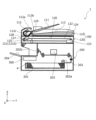
図1で表されるように、プリンター1は、原稿の画像の読み取りを行う読み取り手段1210を備える画像読み取りユニット100と、画像読み取りユニット100で読み取った画像或いは不図示の外部装置などから入力した画像データなどに基づいて記録を行う記録部203を備える記録ユニット200と、を備えている。プリンター1は、画像読み取り装置としての画像読み取りユニット100と、記録装置としての記録ユニット200と、を備える複合機と表現することができる。
As shown in FIG. 1, the
図1及び図2で表されるように、画像読み取りユニット100は、原稿を載置する載置トレイ111と、載置トレイ111に載置された原稿の搬送経路112と、搬送経路112を搬送されて画像が読み取られた原稿が排出される排出トレイ113と、を備える自動原稿搬送ユニット110を有している。図1で表されるように、搬送経路112には原稿を搬送する複数の搬送ローラーと原稿の読み取り位置でもある開口部112cとが設けられ、搬送経路112は挿入部を構成するローラー対112aから排出部を構成するローラー対112bまで原稿を搬送可能に構成されている。
As shown in Figures 1 and 2, the
また、図1で表されるように、画像読み取りユニット100は、読み取り手段1210及び読み取り手段1210の移動機構などが筐体128の内部に設けられた本体ユニット120を有している。読み取り手段1210はキャリッジ121に搭載されており、キャリッジ121は、プーリー124及びプーリー125に架橋されたベルト122に取り付けられている。プーリー124はステッピングモーター123の駆動力により回転可能に構成されている。ステッピングモーター123を回転することで、プーリー124、ベルト122及びプーリー125が回転し、ベルト122の回転に伴ってキャリッジ121はY軸方向に沿って移動する。この際、ステッピングモーター123の代わりにDCモーターを用いても良い。その際には、エンコーダーセンサーを併せて用いることでキャリッジ121の位置を把握しても良い。
As shown in FIG. 1, the
ここで、本実施形態の画像読み取りユニット100は、自動原稿搬送ユニット110により搬送される原稿の画像を読み取り可能である。本体ユニット120の開口部112cと対向する位置には透過部材であるガラス板127が設けられており、図1で表されるようにガラス板127を介して開口部112cと対向する位置に読み取り手段1210を位置させることで、画像読み取りユニット100は自動原稿搬送ユニット110により搬送される原稿の画像を読み取ることができる。なお、本実施形態における読み取り手段1210は、X軸方向に延設され、原稿の幅方向全体を読み取り可能な構成となっている。
Here, the
また、本実施形態の画像読み取りユニット100は、本体ユニット120に原稿を載置可能な透過部材であるガラス板126が設けられている。ガラス板126上に原稿を載置し、キャリッジ121をY軸方向に沿って移動させつつ読み取り手段1210により読み取り動作を行わせることで、画像読み取りユニット100はガラス板126に載置された原稿の画像を読み取ることができる。
In addition, the
なお、図2で表されるように、画像読み取りユニット100は、自動原稿搬送ユニット110と本体ユニット120との間における+X方向側端部に、自動原稿搬送ユニット110と本体ユニット120とを接続する接続部130を備えており、接続部130を回転軸として自動原稿搬送ユニット110を本体ユニット120に対して回転方向Rに回転させることができる。図2で表されるように、自動原稿搬送ユニット110を本体ユニット120に対して開いた状態とすることで、ユーザーは、ガラス板126上に原稿を載置することができる。また、画像読み取りユニット100は、自動原稿搬送ユニット110が本体ユニット120に対して開いた状態となっているか閉じた状態となっているかを検知する開閉センサー131を備えている。
2, the
図1で表されるように、記録ユニット200は、複数の媒体Pを載置可能な載置トレイ201と、載置トレイ201に載置された媒体Pの搬送経路202と、搬送経路202を搬送される媒体Pに記録する記録部203と、搬送経路202を搬送されて記録がなされた媒体Pが排出される排出トレイ204と、を備えている。図1で表されるように、搬送経路202には媒体Pを搬送する複数の搬送ローラーが設けられ、搬送経路202は挿入部を構成するローラー202aから排出部を構成するローラー対202bまで原稿を搬送可能に構成されている。なお、本実施形態の記録部203は媒体Pにインクを吐出して記録を行うインクジェット記録ヘッドであるが、記録部としてインクジェット記録ヘッド以外のものを使用してもよい。
As shown in FIG. 1, the
また、図1で表されるように、記録ユニット200には、本実施形態のプリンター1の全体の駆動の制御をする制御部300が設けられている。本実施形態のプリンター1においては、制御部300は記録ユニット200に設けられているが、制御部300は画像読み取りユニット100に設けられていてもよい。また、画像読み取りユニット100に画像読み取りユニット100の制御をする制御部が設けられ、記録ユニット200に記録ユニット200の駆動の制御をする制御部が設けられていてもよい。
As shown in FIG. 1, the
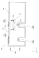
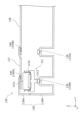
次に、図3から図8を参照して、本実施形態のプリンター1における原稿の画像の読み取りに伴うキャリッジ121の配置に関して詳細に説明する。本実施形態のプリンター1は、載置部としてのガラス板126上に載置された原稿の画像の読み取りを行う第1画像読み取り動作と、自動原稿搬送ユニット110により搬送される原稿の画像の読み取りを行う第2画像読み取り動作と、を行うことが可能に構成されている。ここで、本実施形態のプリンター1においては、キャリッジ121は、電源オフ時、並びに、ガラス板126上に載置された原稿の画像の読み取りを行う際は、図3で表される位置にある。また、キャリッジ121は、電源オン時であって図2で表されるように本体ユニット120に対して自動原稿搬送ユニット110を開いた時には、図4で表される位置にある。また、キャリッジ121は、電源オン時であって本体ユニット120に対して自動原稿搬送ユニット110が閉じている時には、図5で表される位置にある。また、キャリッジ121は、自動原稿搬送ユニット110により原稿を搬送して画像の読み取りを行う第2画像読み取り動作を行う際には、図6で表される位置にある。
Next, the arrangement of the
ここで、キャリッジ121は、図1におけるプーリー124とプーリー125との間に相当する、筐体128の内部における+Y方向側端部から-Y方向側端部まで位置することができる。さらに詳細には、例えば、図3で表される第1画像読み取り動作に伴ってガラス板126上に載置された原稿の画像の読み取りを行う位置である第1画像読み取り位置と、図4で表される第1画像読み取り動作を行う際のホームポジションである第1待機位置と、図5で表される第2画像読み取り動作を行う際のホームポジションである第2待機位置と、図6で表される第2画像読み取り動作に伴って自動原稿搬送ユニット110により搬送される原稿の画像の読み取る位置である第2画像読み取り位置と、に位置することができる。
Here, the
ここで、図3から図6で表されるように、キャリッジ121には読み取りモジュール1211を有する読み取り手段1210が搭載されており、キャリッジ121の-Z方向側端部には、キャリッジの移動方向に所定の幅L1を持つ検知子1212が設けられている。また、筐体128は+Z方向側の筐体である第1筐体128aと-Z方向側の筐体である第2筐体128bとで構成されている。そして、第2筐体128bには検知センサー129として2つの検知センサー129A及び検知センサー129Bが設けられている。検知センサー129は、検知子1212が対向する位置にあるときに検知状態となり、検知子1212が対向する位置にないときに非検知状態となる。
Here, as shown in Figures 3 to 6, the
検知センサー129Aは、図4で表されるようにキャリッジ121が第1待機位置に位置するときに検知子1212と対向する位置にあるように配置されている。検知センサー129は、検知センサー129A及び検知センサー129Bともに、検知センサー129のY軸方向における中央部分で検知子1212を検知する。このため、キャリッジ121が図4で表されるように第1待機位置に位置する状態から所定の幅L1の半分の距離だけ+Y方向側または-Y方向側に移動すると、検知センサー129Aが検知状態から非検知状態に変わる。
As shown in FIG. 4, the
本実施形態のプリンター1は、上記のようにベルト122にキャリッジ121が取り付けられているが、例えば冊子状の原稿を開いてガラス板126上に押し付けるようにして載置し、その状態で原稿の画像の読み取り動作を開始すると、ガラス板126を押し付ける力が本体ユニット120の内部に伝わる。これによって、ガラス板126及び筐体128の内部を構成する構成部材が変形し、キャリッジ121の移動を阻害する。こうした場合、キャリッジ121の実際の位置と、キャリッジ121への指令値から予測した位置とがずれる虞がある。この位置ずれを低減するために、本実施形態のプリンター1は、制御部300の制御により、Y軸方向に沿うキャリッジ121の移動方向における該キャリッジ121の位置ずれを判定する位置ずれ判定動作を実行可能である。詳細には、制御部300は、位置ずれ判定動作として、検知センサー129が検知状態であるときにキャリッジ121の移動を開始し、検知センサー129が検知状態から非検知状態になるまでのキャリッジ121の移動量に基づいてキャリッジ121の位置ずれを判定することができる。
In the
別の表現をすると、本実施形態のプリンター1は、検知子1212の所定の幅L1分に対応するキャリッジ121の短い移動量の移動に基づいてキャリッジ121の位置ずれを判定することができる。したがって、読み取り手段1210が設けられるキャリッジ121の位置ずれを短時間で判定することができる。ここで、「キャリッジ121の移動量に基づいてキャリッジ121の位置ずれを判定する」とは、ステッピングモーター123のステップ数などから推測されるキャリッジ121が所定量移動したと推測される時点において、検知センサー129が検知状態から非検知状態になるかで判定することを意味する。キャリッジ121が所定量移動したと推測される時点の判断は、ステッピングモーター123のステップ数のほか、キャリッジ121の移動に伴う時間などを用いてもよい。また、本実施形態のプリンター1は、媒体Pに記録を行う記録部203を備える。このため、正確な画像の読み取りを迅速に実行して、媒体に該画像の記録を行うことができる。
In other words, the
ここで、本実施形態においては、キャリッジ121の移動量に基づいてキャリッジ121の位置ずれを判定する方法として、キャリッジ121を移動させる駆動部としてのステッピングモーター123のステップ数が検知状態から非検知状態になるまでの理論上のステップ数となっているか否かで判定する方法を用いている。しかしながら、キャリッジの移動量に基づいてキャリッジの位置ずれを判定する方法として、例えば、検知状態から非検知状態になるまでの時間をタイマーなどで計測し計測時間を所定値と比較する方法などを採用することもでき、特に限定は無い。
In this embodiment, the method of determining the positional deviation of the
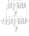
ここで、図8を用いて、プリンター1を用いて行う原稿の画像の読み取りフローの一例を説明する。なお、以下の画像の読み取りフローは、制御部300の制御により行われる。
Here, an example of the flow of reading an image of a document using the
本実施例の原稿の画像の読み取りフローを開始すると、最初に、ステップS10で、制御部300が有するEEPROMなどの記憶部に記憶されたフラグを確認する。ここで、画像の読み取りフローは、フラットベッド(FB)であるガラス板126に載置した原稿の画像を読み取る第1画像読み取り動作の開始要求及び自動原稿搬送ユニット(ADF)110により搬送される原稿の画像の読み取る第2画像読み取り動作の開始要求のほか、載置トレイ111に原稿が載置されたことを不図示のセンサーが検知することやガラス板126に原稿を載置するために開閉センサー131が本体ユニット120に対して自動原稿搬送ユニット110が開いた状態となっていることを検知することなどにより開始されることとしてもよい。また、ステップS10のフラグの確認は、キャリッジ121の位置に関するフラグの確認などである。
When the flow for reading an image of a document in this embodiment is started, first, in step S10, the
次に、ステップS20で、画像の読み取りフローの開始要求が第2画像読み取り動作の開始要求か否かを判断する。第2画像読み取り動作の開始要求の場合ステップS110に進み、第2画像読み取り動作の開始要求ではない場合ステップS210に進む。 Next, in step S20, it is determined whether the request to start the image reading flow is a request to start the second image reading operation. If it is a request to start the second image reading operation, the process proceeds to step S110, and if it is not a request to start the second image reading operation, the process proceeds to step S210.
ステップS110では、図5で表される第2画像読み取り動作における待機位置(ADF HP)にキャリッジ121があることを示すフラグ(ADF HPフラグ)が立っているか否かを制御部300で判断する。ADF HPフラグが0ではない、すなわち、ADF HPにキャリッジ121があると判断された場合はステップS170に進む。一方、ADF HPフラグが0、すなわち、ADF HPにキャリッジ121がないと判断された場合は図4で表される第1画像読み取り動作における待機位置(FB HP)にキャリッジ121があると判断してステップS120に進む。なお、ステップS20からステップS110に進む間に、自動原稿搬送ユニット110の動作エラー確認などを行ってもよい。
In step S110, the
ステップS120では、FB HPから図6で表される第2画像読み取り位置(ADF READ)までキャリッジ121を移動させる。ここで、キャリッジ121がFB HPからADF READまで移動する間に、検知センサー129Aは検知子1212が対向する位置にある検知状態から検知子1212が対向する位置にない非検知状態に切り替わることを検知する。そして、制御部300は、本来検知状態から非検知状態に切り替わるはずの所定のステップ数で検知状態から非検知状態に切り替わったか否かを判断する。具体的には、ステップS130において該所定のステップ数と実測されたステップ数とを比較することによりキャリッジ121が所定以上ベルト122に対してずれているか否かを判断する。ステップS130でキャリッジ121が所定以上ベルト122に対してずれていると制御部300が判断した場合はステップS140を経由してステップS150に進み、ステップS130でキャリッジ121が所定以上ベルト122に対してずれていないと制御部300が判断した場合はステップS140を経由せずにステップS150に進む。
In step S120, the
ステップS140では、キャリッジ121の位置を確認し、ステッピングモーター123を駆動してキャリッジ121の位置を調整する。なお、本ステップは、読み取り手段1210で読み取り可能な被読み取り部である特異パターン140を読み取ることで行われる。図3から図6で表されるように、プリンター1は特異パターン140として特異パターン140Aと特異パターン140Bとを有するが、本実施例では、特異パターン140Aを読み取ることで行われる。特異パターン140Aは、図5で表されるADF HPと図6で表されるADF READとの間の位置にある特異パターン140である。ここでのADF HPとADF READとの間の位置とは、ADF HPにおける読み取りモジュール1211とADF READにおける読み取りモジュール1211の間の位置である。また、ここでのADF HPとADF READとの間の位置とは、ADF HPにおける検知子1212とADF READにおける検知子1212の間の位置としても良い。
In step S140, the position of the
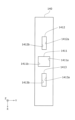
ここで、特異パターン140Aと特異パターン140Bとは全く同じ構成をしており、共に図7で表される形状をしている。キャリッジ121の位置の調整の際は、特異パターン140に形成された開口部1411、開口部1412及び開口部1413のY軸方向側縁部1411a、縁部1411b、縁部1412a、縁部1412b、縁部1413a及び縁部1413bを読み取ることでキャリッジ121の位置を判断する。
Here, the
ステップS150では、ADF READからADF HPまでキャリッジ121を一旦移動させる。キャリッジ121がADF HPまで移動すると、ステップS160でADF HPにキャリッジ121があることを示すフラグを立てる。なお、本実施例ではステップS130及びステップS140をステップS120の直後に実行することとしたが、プリンター1は、ステップS130及びステップS140をステップS160の直後に実行することもできる。
In step S150, the
次に、ステップS170で、ADF HPからADF READまでキャリッジ121を移動させる。そして、ステップS180で、第2画像読み取り動作を開始する。なお、ステップS160とステップS170の間に、第2画像読み取り動作の実行命令が出たのか否かの判断工程や、シェーディングの実行有無の判断工程などを実行するようにしてもよい。
Next, in step S170, the
また、ステップS210では、図5で表される第2画像読み取り動作における待機位置(ADF HP)にキャリッジ121があることを示すフラグ(ADF HPフラグ)が立っているか否かを制御部300で判断する。ADF HPフラグが1ではない、すなわち、ADF HPにキャリッジ121がないと判断された場合は図4で表される第1画像読み取り動作における待機位置(FB HP)にキャリッジ121があると判断してステップS270に進む。一方、ADF HPフラグが1、すなわち、ADF HPにキャリッジ121があると判断された場合はステップS220に進む。
In addition, in step S210, the
ステップS220では、ADF HPからADF READまでキャリッジ121を移動させる。ここで、キャリッジ121がADF HPからADF READまで移動する間に、検知センサー129Bは検知子1212が対向する位置にある検知状態から検知子1212が対向する位置にない非検知状態に切り替わることを検知する。そして、制御部300は、本来検知状態から非検知状態に切り替わるはずの所定のステップ数で検知状態から非検知状態に切り替わったか否かを判断し、ステップS230において所定のステップ数と実測されたステップ数とを比較することによりキャリッジ121が所定以上ベルト122に対してずれているか否かを判断する。ステップS230でキャリッジ121が所定以上ベルト122に対してずれていると制御部300が判断した場合はステップS240を経由してステップS250に進み、ステップS230でキャリッジ121が所定以上ベルト122に対してずれていないと制御部300が判断した場合はステップS240を経由せずにステップS150に進む。
In step S220, the
ステップS240では、キャリッジ121の位置を確認し、ステッピングモーター123を駆動してキャリッジ121の位置を調整する。なお、本ステップは、読み取り手段1210で読み取り可能な被読み取り部である特異パターン140Aを読み取ることで行われる。
In step S240, the position of the
ステップS250では、ADF READからFB HPまでキャリッジ121を移動させる。キャリッジ121がFB HPまで移動すると、ステップS260でADF HPにキャリッジ121があることを示すフラグを解除する。なお、本実施例ではステップS230及びステップS240をステップS220の直後に実行することとしたが、プリンター1は、ステップS230及びステップS240をステップS260の直後に実行することもできる。この場合、ステップS230は、特異パターン140Bを読み取ることで行われることとすることができる。特異パターン140Bは、図4で表されるFB HPと図3で表されるFB READとの間の位置にある特異パターン140である。ここでのFB HPとFB READとの間の位置とは、FB HPにおける読み取りモジュール1211とFB READにおける読み取りモジュール1211の間の位置である。また、ここでのFB HPとFB READとの間の位置とは、FB HPにおける検知子1212とFB READにおける検知子1212の間の位置としても良い。
In step S250, the
次に、ステップS270で、FB HPからFB READまでキャリッジ121を移動させる。そして、ステップS280で、第1画像読み取り動作を開始する。なお、ステップS260とステップS270の間に、第1画像読み取り動作の実行命令が出たのか否かの判断工程などを実行するようにしてもよい。
Next, in step S270, the
本実施形態のキャリッジ121は、ステップS120で表されるように、位置ずれ判定動作開始前にホームポジション(FB HP)に位置するよう構成されている。また、検知センサー129Aは、図4で表されるように、キャリッジ121がFB HPに位置する際に検知子1212と対向する位置に配置されている。そして、制御部300は、ステップS130で表されるように、キャリッジ121がFB HPから原稿の画像の読み取りを行う画像読み取り位置(ADF READ)に向かって移動する際に、位置ずれ判定動作を実行する。
As shown in step S120, the
このように、本実施形態のプリンター1は、キャリッジ121がホームポジションから原稿の画像の読み取りを行う画像読み取り位置に向かって移動する際に位置ずれ判定動作を実行する。すなわち、本実施形態のプリンター1は、原稿の画像の読み取りを行う前に位置ずれ判定動作を実行する。このため、本実施形態のプリンター1は、所定位置まで移動し、所定位置から戻ってくることで位置ずれ判定を行う構成をとらずに済む。そのため、位置ずれ判定動作を実行する際の時間を短縮できる。なお、本実施例の画像の読み取りフローにおいては、ホームポジションは第1画像読み取り動作を実行する前に位置する第1待機位置(FB HP)であるが、このような構成に限定されない。ホームポジションを第2画像読み取り動作を実行する前に位置する第2待機位置(ADF HP)としてもよいし、第1画像読み取り位置(FB READ)や第2画像読み取り位置(ADF READ)など、さらに別の位置としてもかまわない。ここで、ホームポジションをFB HP以外の位置にする場合は、検知センサー129の配置もホームポジションの位置に対応させる必要がある。
In this way, the
また、上記について別の観点から説明すると、本実施形態のプリンター1は、原稿を載置する載置部としてのガラス板126と、原稿を搬送する搬送部としての自動原稿搬送ユニット110と、を備えている。また、制御部300は、ガラス板126に載置された原稿の画像を読み取る第1画像読み取り動作と、自動原稿搬送ユニット110により搬送される原稿の画像を読み取る第2画像読み取り動作と、を実行可能である。また、キャリッジ121は、第1画像読み取り動作を実行する前に位置する図4で表される第1待機位置(FB HP)と、ガラス板126に載置された原稿の画像を読み取り可能な図3で表される第1画像読み取り位置(FB READ)と、第2画像読み取り動作を実行する前に位置する図5で表される第2待機位置(ADF HP)と、自動原稿搬送ユニット110により搬送される原稿の画像を読み取り可能な図6で表される第2画像読み取り位置(ADF READ)と、に移動可能である。そして、制御部300は、第1待機位置(FB HP)をホームポジションとし、ステップS120からステップS150で表されるように、キャリッジ121が第1待機位置(FB HP)から第2待機位置(ADF HP)に向かって移動する際に位置ずれ判定動作を実行することができる。
In addition, to explain the above from another perspective, the
このように、本実施形態のプリンター1は、キャリッジ121が第1待機位置(FB HP)から第2待機位置(ADF HP)に向かって移動する際に位置ずれ判定動作を実行する。このため、自動原稿搬送ユニット110により搬送される原稿の画像を読み取る第2画像読み取り動作を実行する際、該第2画像読み取り動作を実行する前に位置ずれ判定動作を実行する。したがって、第2画像読み取り動作を実行する際、ADF HPから特異パターン140を読み取りに行き再度ADF HPに戻るなどの時間、すなわち、位置ずれ判定動作を実行するための時間を短縮することができる。
In this way, the
また、上記のように、本実施形態のプリンター1は、FB HPとADF HPとの間に、読み取り手段1210で読み取り可能な被読み取り部としての特異パターン140のうちの特異パターン140Aが設けられている。また、制御部300は、キャリッジ121が位置ずれしていると判定した場合、キャリッジ121がFB HPからADF HPに向かって移動する途中において読み取り手段1210で特異パターン140Aを読み取らせることで、キャリッジ121の位置を補正する。このため、キャリッジ121が位置ずれをしていると判定した場合に、ADF HPに移動した後に特異パターン140の位置までキャリッジ121を移動する時間を省略することができる。
As described above, the
なお、本実施例の画像の読み取りフローにおいては、ステップS120からステップS150で表されるように、キャリッジ121が第1待機位置(FB HP)から第2待機位置(ADF HP)に向かって移動する際に位置ずれ判定動作を実行し、キャリッジ121が位置ずれをしていると判定した場合、キャリッジ121が第1待機位置(FB HP)から第2待機位置(ADF HP)に向かって移動する途中で特異パターン140の読み取り動作を実行するが、このような構成に限定されない。キャリッジ121が第1待機位置(FB HP)から第2待機位置(ADF HP)に向かって移動する際に位置ずれ判定動作を実行し、キャリッジ121が位置ずれをしていると判定した場合、第2待機位置(ADF HP)に移動した後に特異パターン140の位置までキャリッジ121を移動し該特異パターン140の読み取り動作を実行してもよい。さらには、特異パターン140を使用せず、エンコーダーなどを用いてリターン時の移動距離を測定し、所望の移動距離とのずれからキャリッジ121の位置ずれを判定してもよい。
In the image reading flow of this embodiment, as represented by steps S120 to S150, a position shift determination operation is performed when the
図3から図6で表されるように、本実施形態のプリンター1は、筐体128として+Z方向側に位置する第1筐体128aと-Z方向側に位置する第2筐体128bとを備えている。第1筐体128aは、載置部としてのガラス板126と、図6で表されるようにキャリッジ121が第2画像読み取り位置にあるときに読み取り手段1210と対向する位置に設けられる透過部材としてのガラス板127と、を有する。また、第2筐体128bは、キャリッジ121をY軸方向に沿って移動可能に支持するとともに、キャリッジ121を介して第1筐体128aと対向する位置に設けられている。ここで、特異パターン140は、第1筐体128aに設けられている。
As shown in Figures 3 to 6, the
このように、本実施形態のプリンター1においては、特異パターン140がキャリッジ121に対して原稿がある側と同じ側の筐体部分に設けられている。第1筐体128aとキャリッジ121を移動可能に支持する第2筐体128bとを組み合わせる際に製造公差により多少のずれが生じる場合があるが、特異パターン140が第1筐体128aに設けられることで、第1筐体128aと第2筐体128bとを組み合わせる際にずれが生じても、原稿がある側と同じ側の筐体部分に設けられる特異パターン140を用いてキャリッジ121の位置を補正することができる。すなわち、本実施形態のプリンター1は、第1筐体128aと第2筐体128bとを組み合わせる際のずれの影響を受けることなく、
原稿がある側と同じ側の筐体部分に対してキャリッジ121の位置を正確に補正することができる。これによって、原稿を正確に読み取ることができる。
Thus, in the
The position of the
ここで、制御部300は、位置ずれ判定動作の開始時に検知センサー129Aが非検知状態である場合、すなわち、位置ずれ判定動作の開始時にキャリッジ121が図4で表される位置にない場合、キャリッジ121が位置ずれしていると判定し、キャリッジ121の位置を補正することができる。したがって、本実施形態のプリンター1は、キャリッジ121の位置ずれが初期段階で発生した場合に、迅速にキャリッジ121の位置を補正することができる。
Here, if the
本発明は上記において説明した各実施形態に限定されることなく、特許請求の範囲に記載した発明の範囲内で、種々の変形が可能であり、それらも本発明の範囲内に含まれるものであることは言うまでもない。 The present invention is not limited to the embodiments described above, and various modifications are possible within the scope of the invention described in the claims, and it goes without saying that these modifications are also included within the scope of the present invention.
1…インクジェットプリンター(画像読み取り装置、記録装置)、100…画像読み取りユニット(画像読み取り装置)、110…自動原稿搬送ユニット(搬送部)、111…載置トレイ、112…搬送経路、112a…ローラー対、112b…ローラー対、112c…開口部、113…排出トレイ、120…本体ユニット、121…キャリッジ、122…ベルト、123…ステッピングモーター、124…プーリー、125…プーリー、126…ガラス板(載置部)、127…ガラス板(透過部材)、128…筐体、128a…第1筐体、128b…第2筐体、129…検知センサー、129A…検知センサー、129B…検知センサー、130…接続部、131…開閉センサー、140…特異パターン(被読み取り部)、140A…特異パターン(被読み取り部)、140B…特異パターン(被読み取り部)、200…記録ユニット(記録装置)、201…載置トレイ、202…搬送経路、202a…ローラー、202b…ローラー対、203…記録部、204…排出トレイ、300…制御部、1210…読み取り手段、1211…読み取りモジュール、1212…検知子、1411…開口部、1411a…縁部、1411b…縁部、1412…開口部、1412a…縁部、1412b…縁部、1413…開口部、1413a…縁部、1413b…縁部、P…媒体 1...inkjet printer (image reading device, recording device), 100...image reading unit (image reading device), 110...automatic document transport unit (transport section), 111...loading tray, 112...transport path, 112a...pair of rollers, 112b...pair of rollers, 112c...opening, 113...output tray, 120...main unit, 121...carriage, 122...belt, 123...stepping motor, 124...pulley, 125...pulley, 126...glass plate (loading section), 127...glass plate (transparent member), 128...housing, 128a...first housing, 128b...second housing, 129...detection sensor, 129A...detection sensor, 129B...detection sensor Ser, 130...connection part, 131...opening/closing sensor, 140...specific pattern (part to be read), 140A...specific pattern (part to be read), 140B...specific pattern (part to be read), 200...recording unit (recording device), 201...loading tray, 202...transport path, 202a...roller, 202b...roller pair, 203...recording part, 204...discharge tray, 300...control part, 1210...reading means, 1211...reading module, 1212...detector, 1411...opening, 1411a...edge, 1411b...edge, 1412...opening, 1412a...edge, 1412b...edge, 1413...opening, 1413a...edge, 1413b...edge, P...medium
Claims (5)
前記読み取り手段が設けられ前記読み取り手段とともに移動するキャリッジと、
前記キャリッジに設けられ前記キャリッジの移動方向に所定の幅を持つ検知子と、
前記検知子が対向する位置にあるときに検知状態とし、前記検知子が対向する位置にな
いときに非検知状態とする検知センサーと、
前記移動方向における前記キャリッジの位置ずれを判定する位置ずれ判定動作を実行可
能な制御部と、
を備え、
前記制御部は、前記位置ずれ判定動作として、前記検知センサーが前記検知状態である
ときに前記キャリッジの移動を開始し前記検知センサーが前記検知状態から前記非検知状
態になるまでの前記キャリッジの移動量に基づいて前記キャリッジの位置ずれを判定し、
前記キャリッジは、前記位置ずれ判定動作開始前にホームポジションに位置するよう構
成され、
前記検知センサーは、前記キャリッジが前記ホームポジションに位置する際に前記検知
子と対向する位置に配置され、
原稿を載置する載置部と、原稿を搬送する搬送部と、を備え、
前記制御部は、前記載置部に載置された原稿の画像を読み取る第1画像読み取り動作と
、前記搬送部により搬送される原稿の画像を読み取る第2画像読み取り動作と、を実行可
能であり、
前記キャリッジは、前記第1画像読み取り動作を実行する前に位置する第1待機位置と
、前記載置部に載置された原稿の画像を読み取り可能な第1画像読み取り位置と、前記第
2画像読み取り動作を実行する前に位置する第2待機位置と、前記搬送部により搬送され
る原稿の画像を読み取り可能な第2画像読み取り位置と、に移動可能であり、
前記制御部は、前記第1待機位置を前記ホームポジションとし、前記キャリッジが前記
ホームポジションから前記第2待機位置側に向かって移動する際に前記位置ずれ判定動作
を実行することを特徴とする画像読み取り装置。 A reading means for reading an image of a document;
a carriage on which the reading means is provided and which moves together with the reading means;
a detector provided on the carriage and having a predetermined width in a moving direction of the carriage;
a detection sensor that is in a detection state when the detector is in a position facing the object and in a non-detection state when the detector is not in a position facing the object;
a control unit capable of executing a positional deviation determination operation for determining a positional deviation of the carriage in the moving direction;
Equipped with
the control unit, as the positional deviation determination operation, starts moving the carriage when the detection sensor is in the detection state , and determines a positional deviation of the carriage based on an amount of movement of the carriage from the detection state to the non-detection state of the detection sensor;
The carriage is configured to be located at a home position before the position deviation determination operation is started.
It was made,
The detection sensor detects the carriage when the carriage is located at the home position.
is placed opposite the child,
The document feeder includes a document placement section and a document transport section,
the control unit performs a first image reading operation of reading an image of the document placed on the document placement unit;
a second image reading operation for reading an image of the document conveyed by the conveying unit;
It is Noh,
the carriage is at a first standby position before performing the first image reading operation;
a first image reading position where an image of a document placed on the document placement section can be read;
a second waiting position where the image reading operation is performed;
a second image reading position where an image of the original can be read;
The control unit sets the first standby position as the home position, and
When moving from the home position toward the second standby position, the position deviation determination operation
An image reading apparatus comprising :
前記ホームポジションと前記第2待機位置との間に、前記読み取り手段で読み取り可能
な被読み取り部が設けられ、
前記制御部は、前記キャリッジが位置ずれしていると判定した場合、前記キャリッジが
前記ホームポジションから前記第2待機位置に向かって移動する途中において前記読み取
り手段で前記被読み取り部を読み取らせることで、前記キャリッジの位置を補正すること
を特徴とする画像読み取り装置。 2. The image reading apparatus according to claim 1 ,
a readable portion that can be read by the reading means is provided between the home position and the second standby position,
An image reading device characterized in that, when the control unit determines that the carriage is misaligned, it corrects the position of the carriage by having the reading means read the read portion while the carriage is moving from the home position toward the second waiting position.
前記載置部と、前記キャリッジが前記第2画像読み取り位置にあるときに前記読み取り
手段と対向する位置に設けられる透過部材と、を有する第1筐体と、
前記キャリッジを移動可能に支持するとともに、前記キャリッジを介して前記第1筐体
と対向する位置に設けられる第2筐体と、
を備え、
前記被読み取り部は、前記第1筐体に設けられることを特徴とする画像読み取り装置。 3. The image reading apparatus according to claim 2 ,
a first housing including the mounting portion and a transparent member provided at a position facing the reading means when the carriage is at the second image reading position;
a second housing that movably supports the carriage and is provided at a position opposite to the first housing with the carriage interposed therebetween;
Equipped with
The image reading device according to claim 1, wherein the read portion is provided in the first housing.
前記制御部は、前記位置ずれ判定動作の開始時に前記検知センサーが前記非検知状態で
ある場合、前記キャリッジが位置ずれしていると判定し、前記キャリッジの位置を補正す
ることを特徴とする画像読み取り装置。 4. The image reading apparatus according to claim 1,
The control unit determines that the carriage is misaligned if the detection sensor is in the non-detecting state at the start of the misalignment determination operation, and corrects the position of the carriage.
前記画像読み取り装置で読み取った原稿の画像に基づいて媒体に記録を行う記録部と、
を備えることを特徴とする記録装置。 An image reading device according to any one of claims 1 to 4 ,
a recording unit that records on a medium based on the image of the document read by the image reading device;
A recording device comprising:
Priority Applications (2)
| Application Number | Priority Date | Filing Date | Title |
|---|---|---|---|
| JP2021011757A JP7608848B2 (en) | 2021-01-28 | 2021-01-28 | Image reading device and recording device |
| US17/648,855 US11652927B2 (en) | 2021-01-28 | 2022-01-25 | Image reading device and recording device |
Applications Claiming Priority (1)
| Application Number | Priority Date | Filing Date | Title |
|---|---|---|---|
| JP2021011757A JP7608848B2 (en) | 2021-01-28 | 2021-01-28 | Image reading device and recording device |
Publications (2)
| Publication Number | Publication Date |
|---|---|
| JP2022115241A JP2022115241A (en) | 2022-08-09 |
| JP7608848B2 true JP7608848B2 (en) | 2025-01-07 |
Family
ID=82494977
Family Applications (1)
| Application Number | Title | Priority Date | Filing Date |
|---|---|---|---|
| JP2021011757A Active JP7608848B2 (en) | 2021-01-28 | 2021-01-28 | Image reading device and recording device |
Country Status (2)
| Country | Link |
|---|---|
| US (1) | US11652927B2 (en) |
| JP (1) | JP7608848B2 (en) |
Citations (4)
| Publication number | Priority date | Publication date | Assignee | Title |
|---|---|---|---|---|
| JP2006010718A (en) | 2004-06-21 | 2006-01-12 | Ricoh Co Ltd | Image reading apparatus and image forming apparatus |
| JP2012044589A (en) | 2010-08-23 | 2012-03-01 | Ricoh Co Ltd | Image reader and image forming apparatus |
| JP2015159351A (en) | 2014-02-21 | 2015-09-03 | 株式会社リコー | Image reading apparatus, image reading apparatus control method, and control program |
| JP2017112403A (en) | 2015-12-14 | 2017-06-22 | キヤノン株式会社 | Image reading device and image forming apparatus |
Family Cites Families (6)
| Publication number | Priority date | Publication date | Assignee | Title |
|---|---|---|---|---|
| JPH04347842A (en) | 1991-05-24 | 1992-12-03 | Ricoh Co Ltd | scanner control device |
| JPH11122993A (en) | 1997-10-16 | 1999-04-30 | Minolta Co Ltd | Scanner controller |
| US20040095619A1 (en) * | 2002-11-15 | 2004-05-20 | Toshiba Tec Kabushiki Kaisha | Image reader for use in image forming apparatus |
| US20070216967A1 (en) * | 2006-03-17 | 2007-09-20 | Kabushiki Kaisha Toshiba | Image scanning apparatus and image copying apparatus |
| JP5978785B2 (en) * | 2012-06-08 | 2016-08-24 | ブラザー工業株式会社 | Image reading apparatus and image forming apparatus |
| US8947690B2 (en) * | 2013-02-08 | 2015-02-03 | Kyocera Document Solutions Inc. | Image reading apparatus and image forming apparatus |
-
2021
- 2021-01-28 JP JP2021011757A patent/JP7608848B2/en active Active
-
2022
- 2022-01-25 US US17/648,855 patent/US11652927B2/en active Active
Patent Citations (4)
| Publication number | Priority date | Publication date | Assignee | Title |
|---|---|---|---|---|
| JP2006010718A (en) | 2004-06-21 | 2006-01-12 | Ricoh Co Ltd | Image reading apparatus and image forming apparatus |
| JP2012044589A (en) | 2010-08-23 | 2012-03-01 | Ricoh Co Ltd | Image reader and image forming apparatus |
| JP2015159351A (en) | 2014-02-21 | 2015-09-03 | 株式会社リコー | Image reading apparatus, image reading apparatus control method, and control program |
| JP2017112403A (en) | 2015-12-14 | 2017-06-22 | キヤノン株式会社 | Image reading device and image forming apparatus |
Also Published As
| Publication number | Publication date |
|---|---|
| JP2022115241A (en) | 2022-08-09 |
| US11652927B2 (en) | 2023-05-16 |
| US20220239787A1 (en) | 2022-07-28 |
Similar Documents
| Publication | Publication Date | Title |
|---|---|---|
| US6356735B1 (en) | Sheet transport device and an image-forming apparatus employing the sheet transport device | |
| US8066279B2 (en) | Sheet conveyance apparatus | |
| US20040156666A1 (en) | Printer and printing method | |
| US7916359B2 (en) | Image forming apparatus | |
| US10759187B2 (en) | Ink-jet recording apparatus and ink-jet recording method | |
| JP2010208718A (en) | Image recording apparatus | |
| US7176649B2 (en) | DC motor control apparatus and recording apparatus | |
| US20030193673A1 (en) | Recording apparatus | |
| JP7608848B2 (en) | Image reading device and recording device | |
| US7027076B2 (en) | Media-position media sensor | |
| US6714757B2 (en) | Image reading apparatus and an image forming apparatus having the image reading apparatus | |
| JP2025061599A (en) | Image recording device, control method thereof, and program | |
| US8721206B2 (en) | Image recording apparatus | |
| US8960840B2 (en) | Image recording apparatus and tray | |
| JP5565247B2 (en) | Image recording device | |
| JP2002354207A (en) | Image scanner | |
| JP7683452B2 (en) | Medium loading device and recording device | |
| CN116890546B (en) | Recording device and method for reading recorded image in recording device | |
| US12088766B2 (en) | Reading apparatus with a displaceable cover member that covers a feed port | |
| JP2001199598A (en) | Printing device | |
| JP4363231B2 (en) | Image forming apparatus | |
| US10864760B2 (en) | Recording apparatus | |
| JP4138332B2 (en) | Printer and control method thereof | |
| JPS63147747A (en) | Image forming device | |
| JP2024164674A (en) | Image forming device |
Legal Events
| Date | Code | Title | Description |
|---|---|---|---|
| RD04 | Notification of resignation of power of attorney |
Free format text: JAPANESE INTERMEDIATE CODE: A7424 Effective date: 20210915 |
|
| RD03 | Notification of appointment of power of attorney |
Free format text: JAPANESE INTERMEDIATE CODE: A7423 Effective date: 20211104 |
|
| A621 | Written request for application examination |
Free format text: JAPANESE INTERMEDIATE CODE: A621 Effective date: 20231204 |
|
| A977 | Report on retrieval |
Free format text: JAPANESE INTERMEDIATE CODE: A971007 Effective date: 20240829 |
|
| A131 | Notification of reasons for refusal |
Free format text: JAPANESE INTERMEDIATE CODE: A131 Effective date: 20240910 |
|
| A521 | Request for written amendment filed |
Free format text: JAPANESE INTERMEDIATE CODE: A523 Effective date: 20241030 |
|
| TRDD | Decision of grant or rejection written | ||
| A01 | Written decision to grant a patent or to grant a registration (utility model) |
Free format text: JAPANESE INTERMEDIATE CODE: A01 Effective date: 20241119 |
|
| A61 | First payment of annual fees (during grant procedure) |
Free format text: JAPANESE INTERMEDIATE CODE: A61 Effective date: 20241202 |
|
| R150 | Certificate of patent or registration of utility model |
Ref document number: 7608848 Country of ref document: JP Free format text: JAPANESE INTERMEDIATE CODE: R150 |