JP7608823B2 - Pneumatic tires - Google Patents
Pneumatic tires Download PDFInfo
- Publication number
- JP7608823B2 JP7608823B2 JP2020215292A JP2020215292A JP7608823B2 JP 7608823 B2 JP7608823 B2 JP 7608823B2 JP 2020215292 A JP2020215292 A JP 2020215292A JP 2020215292 A JP2020215292 A JP 2020215292A JP 7608823 B2 JP7608823 B2 JP 7608823B2
- Authority
- JP
- Japan
- Prior art keywords
- rubber
- rubber layer
- sidewall
- tread
- different color
- Prior art date
- Legal status (The legal status is an assumption and is not a legal conclusion. Google has not performed a legal analysis and makes no representation as to the accuracy of the status listed.)
- Active
Links
Images
Classifications
-
- B—PERFORMING OPERATIONS; TRANSPORTING
- B60—VEHICLES IN GENERAL
- B60C—VEHICLE TYRES; TYRE INFLATION; TYRE CHANGING; CONNECTING VALVES TO INFLATABLE ELASTIC BODIES IN GENERAL; DEVICES OR ARRANGEMENTS RELATED TO TYRES
- B60C13/00—Tyre sidewalls; Protecting, decorating, marking, or the like, thereof
- B60C13/04—Tyre sidewalls; Protecting, decorating, marking, or the like, thereof having annular inlays or covers, e.g. white sidewalls
-
- B—PERFORMING OPERATIONS; TRANSPORTING
- B60—VEHICLES IN GENERAL
- B60C—VEHICLE TYRES; TYRE INFLATION; TYRE CHANGING; CONNECTING VALVES TO INFLATABLE ELASTIC BODIES IN GENERAL; DEVICES OR ARRANGEMENTS RELATED TO TYRES
- B60C13/00—Tyre sidewalls; Protecting, decorating, marking, or the like, thereof
- B60C13/001—Decorating, marking or the like
-
- B—PERFORMING OPERATIONS; TRANSPORTING
- B60—VEHICLES IN GENERAL
- B60C—VEHICLE TYRES; TYRE INFLATION; TYRE CHANGING; CONNECTING VALVES TO INFLATABLE ELASTIC BODIES IN GENERAL; DEVICES OR ARRANGEMENTS RELATED TO TYRES
- B60C1/00—Tyres characterised by the chemical composition or the physical arrangement or mixture of the composition
- B60C1/0025—Compositions of the sidewalls
-
- B—PERFORMING OPERATIONS; TRANSPORTING
- B60—VEHICLES IN GENERAL
- B60C—VEHICLE TYRES; TYRE INFLATION; TYRE CHANGING; CONNECTING VALVES TO INFLATABLE ELASTIC BODIES IN GENERAL; DEVICES OR ARRANGEMENTS RELATED TO TYRES
- B60C13/00—Tyre sidewalls; Protecting, decorating, marking, or the like, thereof
- B60C13/02—Arrangement of grooves or ribs
-
- B—PERFORMING OPERATIONS; TRANSPORTING
- B60—VEHICLES IN GENERAL
- B60C—VEHICLE TYRES; TYRE INFLATION; TYRE CHANGING; CONNECTING VALVES TO INFLATABLE ELASTIC BODIES IN GENERAL; DEVICES OR ARRANGEMENTS RELATED TO TYRES
- B60C13/00—Tyre sidewalls; Protecting, decorating, marking, or the like, thereof
- B60C2013/005—Physical properties of the sidewall rubber
-
- B—PERFORMING OPERATIONS; TRANSPORTING
- B60—VEHICLES IN GENERAL
- B60C—VEHICLE TYRES; TYRE INFLATION; TYRE CHANGING; CONNECTING VALVES TO INFLATABLE ELASTIC BODIES IN GENERAL; DEVICES OR ARRANGEMENTS RELATED TO TYRES
- B60C13/00—Tyre sidewalls; Protecting, decorating, marking, or the like, thereof
- B60C13/04—Tyre sidewalls; Protecting, decorating, marking, or the like, thereof having annular inlays or covers, e.g. white sidewalls
- B60C2013/045—Tyre sidewalls; Protecting, decorating, marking, or the like, thereof having annular inlays or covers, e.g. white sidewalls comprising different sidewall rubber layers
-
- Y—GENERAL TAGGING OF NEW TECHNOLOGICAL DEVELOPMENTS; GENERAL TAGGING OF CROSS-SECTIONAL TECHNOLOGIES SPANNING OVER SEVERAL SECTIONS OF THE IPC; TECHNICAL SUBJECTS COVERED BY FORMER USPC CROSS-REFERENCE ART COLLECTIONS [XRACs] AND DIGESTS
- Y02—TECHNOLOGIES OR APPLICATIONS FOR MITIGATION OR ADAPTATION AGAINST CLIMATE CHANGE
- Y02T—CLIMATE CHANGE MITIGATION TECHNOLOGIES RELATED TO TRANSPORTATION
- Y02T10/00—Road transport of goods or passengers
- Y02T10/80—Technologies aiming to reduce greenhouse gasses emissions common to all road transportation technologies
- Y02T10/86—Optimisation of rolling resistance, e.g. weight reduction
Landscapes
- Engineering & Computer Science (AREA)
- Mechanical Engineering (AREA)
- Tires In General (AREA)
Description
本発明は、空気入りタイヤに関する。 The present invention relates to a pneumatic tire.
下記特許文献1には、サイドウォール部に凸状模様が形成された空気入りタイヤが提案されている。前記空気入りタイヤは、サイドウォール部の内部に、非黒色ゴム層を有し、前記凸状模様の隆起面に、前記非黒色ゴム層の一部が露出している。 Patent Document 1 below proposes a pneumatic tire with a convex pattern formed on the sidewall portion. The pneumatic tire has a non-black rubber layer inside the sidewall portion, and a part of the non-black rubber layer is exposed on the raised surface of the convex pattern.
特許文献1の空気入りタイヤは、露出した異色ゴム層によって外観の向上を期待している。 The pneumatic tire in Patent Document 1 is expected to have an improved appearance due to the exposed different color rubber layer.
しかしながら、前記異色ゴム層は、その周囲のゴム部材から老化防止剤等のゴム配合剤が移行して、変色し易いという問題があった。とりわけ、近年では、サイドウォール部が薄肉化しており、カーカスのトッピングゴムのゴム配合剤が異色ゴム層に移行して上述の変色が発生し易い傾向があった。 However, the different-colored rubber layer has a problem in that rubber compounding agents such as antioxidants migrate from the surrounding rubber materials, causing discoloration. In particular, in recent years, sidewalls have become thinner, and the rubber compounding agents of the carcass topping rubber tend to migrate to the different-colored rubber layer, causing the above-mentioned discoloration.
本発明は、以上のような実情に鑑み案出されたもので、サイドウォール部の外面に異色ゴム層が露出した空気入りタイヤにおいて、異色ゴム層の変色を抑制することを主たる目的としている。 The present invention was devised in consideration of the above-mentioned circumstances, and its main purpose is to suppress discoloration of a different-colored rubber layer in a pneumatic tire in which the different-colored rubber layer is exposed on the outer surface of the sidewall portion.
本発明は、空気入りタイヤであって、トレッド部と、一対のサイドウォール部と、一対のビード部と、一方の前記ビード部から他方の前記ビード部に至るカーカスとを含み、前記一対のサイドウォール部の少なくとも一方は、前記カーカスのタイヤ軸方向外側に配された第1サイドウォールゴムを含み、前記第1サイドウォールゴムは、異色ゴム層と、バリアゴム層とを含み、前記異色ゴム層は、前記サイドウォール部の外面の基本色とは異なる色を有し、かつ、その少なくとも一部が前記サイドウォール部の外面に露出しており、前記バリアゴム層は、前記異色ゴム層と前記カーカスとの間に配され、かつ、前記カーカス側のゴム配合剤が前記異色ゴム層に移行するのを抑制するゴム配合を備えた第1部分を含む。 The present invention is a pneumatic tire that includes a tread portion, a pair of sidewall portions, a pair of bead portions, and a carcass extending from one of the bead portions to the other of the bead portions, and at least one of the pair of sidewall portions includes a first sidewall rubber arranged on the axially outer side of the carcass, and the first sidewall rubber includes a different color rubber layer and a barrier rubber layer, and the different color rubber layer has a color different from the basic color of the outer surface of the sidewall portion, and at least a portion of the different color rubber layer is exposed on the outer surface of the sidewall portion, and the barrier rubber layer is arranged between the different color rubber layer and the carcass, and includes a first portion having a rubber compounding that suppresses the rubber compounding agent on the carcass side from migrating to the different color rubber layer.
本発明の空気入りタイヤにおいて、前記一対のビード部は、それぞれの外面を構成するクリンチゴムを含み、前記第1サイドウォールゴムは、前記クリンチゴムと接する内側ゴム部を含み、前記バリアゴム層は、前記内側ゴム部と前記異色ゴム層との間に配され、かつ、前記内側ゴム部のゴム配合剤が前記異色ゴム層に移行するのを抑制するゴム配合を備えた第2部分を含むのが望ましい。 In the pneumatic tire of the present invention, it is preferable that the pair of bead portions include clinch rubber constituting the respective outer surfaces, the first sidewall rubber includes an inner rubber portion that contacts the clinch rubber, and the barrier rubber layer includes a second portion that is disposed between the inner rubber portion and the different color rubber layer and has a rubber compounding that inhibits the rubber compounding agent of the inner rubber portion from migrating to the different color rubber layer.
本発明の空気入りタイヤにおいて、前記バリアゴム層は、前記トレッド部を構成するトレッドゴムと前記異色ゴム層との間に配され、かつ、前記トレッドゴム側のゴム配合剤が前記異色ゴム層に移行するのを抑制するゴム配合を備えた第3部分を含むのが望ましい。 In the pneumatic tire of the present invention, it is preferable that the barrier rubber layer is disposed between the tread rubber constituting the tread portion and the different-color rubber layer, and includes a third portion having a rubber compounding that suppresses the rubber compounding agent on the tread rubber side from migrating to the different-color rubber layer.
本発明の空気入りタイヤにおいて、タイヤ子午線断面において、前記第1サイドウォールゴムのタイヤ半径方向の外端からトレッド接地端までの距離は、20~40mmであるのが望ましい。 In the pneumatic tire of the present invention, it is desirable that the distance from the radial outer edge of the first sidewall rubber to the tread ground edge in the tire meridian cross section is 20 to 40 mm.
本発明の空気入りタイヤにおいて、トレッド用金型で加硫成型された第1外面と、サイドウォール用金型で加硫成型された第2外面との境界を含み、前記異色ゴム層は、前記境界よりもタイヤ半径方向内側に配されており、タイヤ子午線断面において、前記境界から前記異色ゴム層のタイヤ半径方向の外端までの距離は、10~30mmであるのが望ましい。 The pneumatic tire of the present invention includes a boundary between a first outer surface vulcanized in a tread mold and a second outer surface vulcanized in a sidewall mold, and the different color rubber layer is disposed radially inward of the boundary, and the distance from the boundary to the outer end of the different color rubber layer in the radial direction of the tire is desirably 10 to 30 mm in the tire meridian cross section.
本発明の空気入りタイヤにおいて、前記トレッド部は、トレッドゴムを含み、前記トレッドゴムのタイヤ軸方向の外端は、前記第1サイドウォールゴムに覆われているのが望ましい。 In the pneumatic tire of the present invention, it is preferable that the tread portion includes a tread rubber, and that the axially outer end of the tread rubber is covered by the first sidewall rubber.
本発明の空気入りタイヤにおいて、セクションハイトが120mm以下であるのが望ましい。 In the pneumatic tire of the present invention, it is desirable for the section height to be 120 mm or less.
本発明の空気入りタイヤにおいて、前記バリアゴム層は、60%以下のブチル系ゴムを含むのが望ましい。 In the pneumatic tire of the present invention, it is desirable that the barrier rubber layer contains 60% or less of butyl-based rubber.
本発明の空気入りタイヤは、上記の構成を採用したことによって、異色ゴム層が変色するのを抑制することができる。 By adopting the above-mentioned configuration, the pneumatic tire of the present invention can suppress discoloration of the different-color rubber layer.
以下、本発明の実施の一形態が図面に基づき説明される。
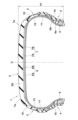
図1は、本実施形態の正規状態における空気入りタイヤ(以下、単に「タイヤ」という場合がある。)1の横断面図が示されている。なお、図1は、タイヤの回転軸を含む所謂タイヤ子午線断面図である。図1に示されるように、本実施形態のタイヤ1は、例えば、乗用車用のタイヤであって、セクションハイトh1が120mm以下の比較的低扁平のタイヤである。但し、本発明は、このような態様に限定されるものではない。
Hereinafter, an embodiment of the present invention will be described with reference to the drawings.
Fig. 1 shows a cross-sectional view of a pneumatic tire (hereinafter, sometimes simply referred to as "tire") 1 in a normal state according to this embodiment. Note that Fig. 1 is a so-called tire meridian cross-sectional view including the rotation axis of the tire. As shown in Fig. 1, the tire 1 of this embodiment is, for example, a tire for passenger cars, and is a relatively low-profile tire with a section height h1 of 120 mm or less. However, the present invention is not limited to this embodiment.
「正規状態」とは、各種の規格が定められた空気入りタイヤの場合、タイヤが正規リム(図示省略)にリム組みされかつ正規内圧が充填され、しかも、無負荷の状態である。各種の規格が定められていないタイヤの場合、前記正規状態は、タイヤの使用目的に応じた標準的な使用状態であって車両に未装着かつ無負荷の状態を意味する。本明細書において、特に断りがない場合、タイヤ各部の寸法等は、前記正規状態で測定された値である。 In the case of a pneumatic tire for which various standards are established, the "normal state" refers to a state in which the tire is mounted on a normal rim (not shown), inflated to the normal internal pressure, and unloaded. In the case of a tire for which various standards are not established, the normal state refers to a standard usage state according to the intended use of the tire, in which the tire is not mounted on a vehicle and is unloaded. In this specification, unless otherwise specified, the dimensions of each part of the tire are values measured in the normal state.
「正規リム」は、タイヤが基づいている規格を含む規格体系において、当該規格がタイヤ毎に定めているリムであり、例えばJATMAであれば "標準リム" 、TRAであれば "Design Rim" 、ETRTOであれば"Measuring Rim" である。 A "genuine rim" is a rim that is specified for each tire by the standard system that includes the standard on which the tire is based. For example, in the case of JATMA, it is called a "standard rim," in the case of TRA, it is called a "design rim," and in the case of ETRTO, it is called a "measuring rim."
「正規内圧」は、タイヤが基づいている規格を含む規格体系において、各規格がタイヤ毎に定めている空気圧であり、JATMAであれば "最高空気圧" 、TRAであれば表 "TIRE LOAD LIMITS AT VARIOUS COLD INFLATION PRESSURES" に記載の最大値、ETRTOであれば "INFLATION PRESSURE" である。 "Normal internal pressure" is the air pressure set for each tire by each standard in the standard system on which the tire is based. For JATMA, it is the "maximum air pressure." For TRA, it is the maximum value listed in the table "TIRE LOAD LIMITS AT VARIOUS COLD INFLATION PRESSURES." For ETRTO, it is the "INFLATION PRESSURE."
セクションハイトh1は、前記正規状態における、ビードベースラインからのタイヤ1のタイヤ半径方向の高さを意味する。また、ビードベースラインは、タイヤが基づく規格で定まるリム径位置を通るタイヤ軸方向線である。 The section height h1 means the height of the tire 1 in the radial direction from the bead baseline in the normal state. The bead baseline is the axial line of the tire that passes through the rim diameter position determined by the standard on which the tire is based.
本実施形態のタイヤ1は、トレッド部2と、一対のサイドウォール部3と、一対のビード部4と、一方のビード部4から他方のビード部4に至るカーカス6とを含む。
The tire 1 of this embodiment includes a
カーカス6は、例えば、2枚のカーカスプライ6A、6Bで構成されている。カーカスプライ6A、6Bは、例えば、複数のカーカスコードと、これらを被覆するトッピングゴムとを含む。カーカスコードは、例えば、タイヤ周方向に対して75~90°の角度で配列されている。カーカスコードには、例えば、ナイロン、ポリエステル又はレーヨン等の有機繊維コード等が好適に採用される。
The
カーカス6は、本体部6a及び折返し部6bを有する。本体部6aは、一対のビード部4のビードコア5間を延びている。折返し部6bは、本体部6aに連なりかつビードコア5の周りで折り返されてタイヤ半径方向外側に延びている。本実施形態の折返し部6bは、ビードコア5の周りをタイヤ軸方向内側から外側に折り返されている。また、折返し部6bにおいて、一方のカーカスプライ6Aの外端と他方のカーカスプライ6Bの外端とは、タイヤ半径方向に位置ずれしている。
The
本実施形態のトレッド部2において、カーカス6のタイヤ半径方向外側には、例えば、ベルト層7が配されている。ベルト層7は、例えば、2枚のベルトプライ7A、7Bを含んでいる。各ベルトプライ7A、7Bは、例えば、タイヤ周方向に対して傾斜して配されたベルトコードと、これを被覆するトッピングゴムとを含む。各ベルトコードは、タイヤ周方向に対して10~45°の角度で傾斜しているのが望ましい。
In the
トレッド部2は、トレッドゴム2Gを含む。一対のビード部4は、その外面を構成するクリンチゴム15を含む。一対のサイドウォール部3の少なくとも一方は、カーカス6のタイヤ軸方向外側に配された第1サイドウォールゴム10を含む。
The
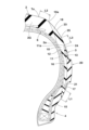
図2には、サイドウォール部3の拡大断面図が示されている。図2に示されるように、また、第1サイドウォールゴム10は、異色ゴム層11と、バリアゴム層12とを含む。
Figure 2 shows an enlarged cross-sectional view of the
異色ゴム層11は、サイドウォール部3の外面の基本色(本実施形態では黒色である)とは異なる色(本実施形態では白色である)を有し、かつ、その少なくとも一部がサイドウォール部3の外面に露出している。本実施形態では、異色ゴム層11の大半が前記基本色で構成されたカバーゴム層13で覆われており、異色ゴム層11の一部が文字やマーク、図形を描くように露出している。
The different
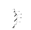
図3には、異色ゴム層11が露出している部分(隆起部)の拡大断面図が示されている。本実施形態では、サイドウォール部3の外面に隆起部20が設けられており、そのタイヤ軸方向外側の頂面20tにおいて異色ゴム層11が露出している。本実施形態のタイヤ1の製造方法では、例えば、カバーゴム層13で覆われた異色ゴム層11を含むサイドウォール部3の一部が、対応する加硫金型の凹部に入り込んで隆起部20が構成された後、異色ゴム層11が露出するように、隆起部20の頂面がバフ掛けされる。このような製造方法は公知であり、本実施形態のタイヤ1に好適に適用される。なお、図2では、隆起部20の断面ではなく、隆起部20の側面が示されている。
Figure 3 shows an enlarged cross-sectional view of the portion (protruding portion) where the different-
本発明では、異色ゴム層11が露出すれば良く、上述の隆起部20を備えないタイヤに本発明が適用されても良い。
In the present invention, it is sufficient that the different
図2に示されるように、バリアゴム層12は、異色ゴム層11とカーカス6との間に配され、かつ、カーカス6側のゴム配合剤が異色ゴム層11に移行するのを抑制するゴム配合を備えた第1部分16を含む。本発明では、上記の構成を採用したことによって、異色ゴム層11が変色するのを抑制することができる。その理由としては、以下のメカニズムが推察される。
As shown in FIG. 2, the
従来から、異色ゴム層11は、その周囲のゴム部材から老化防止剤等のゴム配合剤が移行し、かつ、紫外線等の影響も受けることにより、変色し、サイドウォール部3の外観を損ねる傾向があった。発明者らは、鋭意研究の結果、前記変色は、カーカス6のトッピングゴムに含まれるゴム配合剤の影響が大きいことを突き止めた。また、近年では、サイドウォール部が薄肉化しているため、カーカス6と異色ゴム層11との距離が小さく、カーカス6のトッピングゴムの影響がより大きくなっていることも判明した。本発明では、上述のバリアゴム層12の第1部分16によって、カーカス6のトッピングゴムからのゴム配合剤の移行が抑制され、異色ゴム層11が変色するのを効果的に抑制できると推察される。
Conventionally, the different-
以下、本実施形態のさらに詳細な構成が説明される。なお、以下で説明される各構成は、本実施形態の具体的態様を示すものである。したがって、本発明は、以下で説明される構成を具えないものであっても、上述の効果を発揮し得るのは言うまでもない。また、上述の特徴を具えた本発明のタイヤに、以下で説明される各構成のいずれか1つが単独で適用されても、各構成に応じた性能の向上は期待できる。さらに、以下で説明される各構成のいくつかが複合して適用された場合、各構成に応じた複合的な性能の向上が期待できる。 The following describes the configuration of this embodiment in more detail. Each of the configurations described below represents a specific aspect of this embodiment. Therefore, it goes without saying that the present invention can achieve the above-mentioned effects even if it does not have the configurations described below. Furthermore, even if any one of the configurations described below is applied alone to a tire of the present invention having the above-mentioned characteristics, an improvement in performance corresponding to each configuration can be expected. Furthermore, when several of the configurations described below are applied in combination, a composite improvement in performance corresponding to each configuration can be expected.
バリアゴム層12は、全体が同一のゴム配合で構成されている。バリアゴム層12のゴム配合は、例えば、ブチル系ゴムを含む。ブチル系ゴムは極めて低い空気透過率を示し、ゴム配合剤の移行を効果的に抑制できる。一方、ブチル系ゴムを含んだゴム層がリムと接触すると、リムが腐食するおそれがある。このような観点から、バリアゴム層12は、60%以下のブチル系ゴムを含むのが望ましく、より望ましくは40%~60%のブチル系ゴムを含むのが望ましい。
The
また、バリアゴム層12は、カオリンクレー、クレー、マイカ、長石、シリカおよびアルミナの含水複合体等の無機粘土鉱物を含むのが望ましい。これにより、前記ゴム配合剤の移行がより一層抑制され得る。なお、本発明のバリアゴム層12には、公知のゴム配合を適用することができる。
The
第1サイドウォールゴム10は、ビード部4のクリンチゴム15と接する内側ゴム部21を含む。内側ゴム部21は、一般的なサイドウォールゴムのゴム配合で構成されている。これにより、第1サイドウォールゴム10とクリンチゴム15との境界付近での耐久性が向上する。また、耐久性を十分に確保する観点から、タイヤ子午線断面における、サイドウォール部3又はビード部4の外面に沿った内側ゴム部21の長さL1は、10mm以上であり、望ましくは10~30mmである。
The
また、バリアゴム層12は、内側ゴム部21と異色ゴム層11との間に配された第2部分17を含む。第2部分17は、内側ゴム部21のゴム配合剤が異色ゴム層11に移行するのを抑制するゴム配合を備えているのは言うまでもない。これにより、内側ゴム部21から異色ゴム層11へのゴム配合剤の移行が抑制される。
The
バリアゴム層12は、トレッドゴム2Gと異色ゴム層11との間に配される第3部分18を含む。第3部分18は、トレッドゴム2G側のゴム配合剤が異色ゴム層11に移行するのを抑制するゴム配合を備えているのは言うまでもない。これにより、トレッドゴム2Gから異色ゴム層11へのゴム配合剤の移行が抑制される。
The
本実施形態では、トレッドゴム2Gのタイヤ軸方向の外端2aは、第1サイドウォールゴム10に覆われているのが望ましい。これにより、バリアゴム層12を含む第1サイドウォールゴム10とトレッドゴム2Gとの境界付近の耐久性が向上する。
In this embodiment, it is desirable that the axially
同様の観点から、タイヤ子午線断面において、第1サイドウォールゴム10のタイヤ半径方向の外端10aからトレッド接地端Teまでの距離L2は、20~40mmであるのが望ましい。なお、トレッド接地端Teとは、前記正規状態のタイヤ1に正規荷重が負荷されキャンバー角0°で平面に接地したときの最もタイヤ軸方向外側の接地位置に相当する。
From the same viewpoint, in the tire meridian cross section, the distance L2 from the tire radial
「正規荷重」は、各種の規格が定められた空気入りタイヤの場合、タイヤが基づいている規格を含む規格体系において、各規格がタイヤ毎に定めている荷重であり、JATMAであれば "最大負荷能力" 、TRAであれば表 "TIRE LOAD LIMITS AT VARIOUS COLD INFLATION PRESSURES" に記載の最大値、ETRTOであれば "LOAD CAPACITY" である。また、各種の規格が定められていないタイヤの場合、「正規荷重」は、タイヤの標準装着状態において、1つのタイヤに作用する荷重を指す。前記「標準装着状態」とは、タイヤの使用目的に応じた標準的な車両にタイヤが装着され、かつ、前記車両が走行可能な状態で平坦な路面上に静止している状態を指す。 In the case of pneumatic tires for which various standards are established, the "normal load" is the load that is established for each tire in the standard system including the standards on which the tire is based, and is the "maximum load capacity" for JATMA, the maximum value listed in the table "TIRE LOAD LIMITS AT VARIOUS COLD INFLATION PRESSURES" for TRA, and "LOAD CAPACITY" for ETRTO. In addition, in the case of tires for which various standards are not established, the "normal load" refers to the load acting on a single tire in the standard mounting state of the tire. The "standard mounting state" refers to the state in which the tire is mounted on a standard vehicle corresponding to the intended use of the tire, and the vehicle is stationary on a flat road surface in a drivable state.
異色ゴム層11は、その外面を覆うカバーゴム層13を除き、バリアゴム層12のみに接触しており、その他のゴム部材と接していない。これにより、ゴム配合剤の移行が確実に抑制される。
The different-
タイヤ1の外面は、トレッド用金型で加硫成型された第1外面23と、サイドウォール用金型で加硫成型された第2外面24との境界25を含む。一般に、前記境界25には、2つの金型間の隙間にゴムが入り込むことで僅かなバリが発生する傾向がある。すなわち、境界25付近では、加硫成型時のゴムの移動が大きい。本実施形態のように、セクションハイトが比較的小さいタイヤ1は、境界25と異色ゴム層11とが接近し、境界25付近のゴムの移動によって、意図していない箇所で異色ゴム層11が露出するおそれがある。このような不具合を防ぐため、異色ゴム層11は、この境界25よりもタイヤ半径方向内側に配されている。また、タイヤ子午線断面において、境界25から異色ゴム層11のタイヤ半径方向の外端11aまでの距離L3は、例えば、10~30mmであるのが望ましい。
The outer surface of the tire 1 includes a
カバーゴム層13は、例えば、異色ゴム層11が不必要な箇所で露出するのを防ぐための十分な厚さを有する。一方、カバーゴム層13の厚さが過度に大きいと、上述のバフ掛けの作業性が低下するおそれがある。このような観点から、カバーゴム層13は、0.5~1.0mmであるのが望ましい。
The
より望ましい態様では、カバーゴム層13は、バリアゴム層12と同じゴム配合で構成されている。これにより、カバーゴム層13の剥離が抑制される。
In a more desirable embodiment, the
以上、本発明の空気入りタイヤの好ましい実施形態が詳細に説明されたが、本発明は、上記の具体的な実施形態に限定されることなく、種々の態様に変更して実施され得る。 The above describes in detail preferred embodiments of the pneumatic tire of the present invention, but the present invention is not limited to the specific embodiments described above and can be modified and implemented in various ways.
図1の基本構造を有するサイズ225/50R18の空気入りタイヤが、表1の仕様に基づき試作された。比較例として、カーカスと異色ゴム層との間にバリアゴム層が配されていない空気入りタイヤ試作された。比較例のタイヤは、上述の事項を除き、実施例のタイヤと実質的に同じ構成を有している。各テストタイヤについて、異色ゴム層の耐変色性能がテストされた。各テストタイヤの共通仕様やテスト方法は、以下の通りである。
リム:18×7.0J
タイヤ内圧:220kPa
A pneumatic tire of size 225/50R18 having the basic structure of FIG. 1 was prototyped based on the specifications of Table 1. As a comparative example, a pneumatic tire in which a barrier rubber layer was not disposed between the carcass and the different color rubber layer was prototyped. The comparative tire has substantially the same structure as the tire of the example, except for the above-mentioned points. The discoloration resistance performance of the different color rubber layer was tested for each test tire. The common specifications and test methods of each test tire are as follows.
Rim: 18 x 7.0J
Tire pressure: 220kPa
<異色ゴム層の耐変色性能>
テストタイヤを、ドラム試験機上で一定の縦荷重を負荷して速度80km/hで18時間走行させた。また、この走行中、サイドウォール部の異色ゴム層が露出した箇所にブラックライトを用いて紫外線を照射し続けた。前記走行後、異色ゴム層の露出した箇所の変色度合いが目視で評価された。結果は、1~5点の5段階で示されており、点数が高い程、耐変色性能が優れていることを示す。
テストの結果が表1に示される。
<Discoloration resistance of different color rubber layers>
The test tire was run on a drum tester at a speed of 80 km/h for 18 hours with a constant vertical load. During the run, ultraviolet light was continuously irradiated using a black light on the exposed part of the different-colored rubber layer of the sidewall. After the run, the degree of discoloration of the exposed part of the different-colored rubber layer was visually evaluated. The results were shown on a 5-point scale from 1 to 5, with the higher the score, the better the discoloration resistance performance.
The results of the tests are shown in Table 1.

テストの結果、実施例のタイヤは、異色ゴム層の耐変色性能が4~5点となっており、異色ゴム層の変色を効果的に抑制していることが確認できた。 As a result of the test, the discoloration resistance performance of the different-colored rubber layer of the tire of the embodiment was rated at 4 to 5 points, confirming that discoloration of the different-colored rubber layer was effectively suppressed.
2 トレッド部
3 サイドウォール部
4 ビード部
6 カーカス
10 第1サイドウォールゴム
11 異色ゴム層
12 バリアゴム層
16 第1部分
Claims (7)
トレッド部と、一対のサイドウォール部と、一対のビード部と、一方の前記ビード部から他方の前記ビード部に至るカーカスとを含み、
前記一対のサイドウォール部の少なくとも一方は、前記カーカスのタイヤ軸方向外側に配された第1サイドウォールゴムを含み、
前記第1サイドウォールゴムは、異色ゴム層と、バリアゴム層とを含み、
前記異色ゴム層は、前記サイドウォール部の外面の基本色とは異なる色を有し、かつ、その少なくとも一部が前記サイドウォール部の外面に露出しており、
前記バリアゴム層は、前記異色ゴム層と前記カーカスとの間に配され、かつ、前記カーカス側のゴム配合剤が前記異色ゴム層に移行するのを抑制するゴム配合を備えた第1部分を含み、
トレッド用金型で加硫成型された第1外面と、サイドウォール用金型で加硫成型された第2外面との境界を含み、
前記異色ゴム層は、前記境界よりもタイヤ半径方向内側に配されており、
タイヤ子午線断面において、前記境界から前記異色ゴム層のタイヤ半径方向の外端までの距離は、10~30mmである、
空気入りタイヤ。 A pneumatic tire,
The tire includes a tread portion, a pair of sidewall portions, a pair of bead portions, and a carcass extending from one of the bead portions to the other of the bead portions,
At least one of the pair of sidewall portions includes a first sidewall rubber disposed axially outward of the carcass,
The first sidewall rubber includes a different color rubber layer and a barrier rubber layer,
the different color rubber layer has a color different from a basic color of the outer surface of the sidewall portion, and at least a part of the different color rubber layer is exposed to the outer surface of the sidewall portion,
the barrier rubber layer includes a first portion disposed between the different color rubber layer and the carcass and having a rubber compounding agent on the carcass side that inhibits migration of the rubber compounding agent on the carcass side to the different color rubber layer,
The tire includes a boundary between a first outer surface vulcanized and molded in a tread mold and a second outer surface vulcanized and molded in a sidewall mold,
the different color rubber layer is disposed radially inward of the boundary,
In a tire meridian cross section, a distance from the boundary to an outer end of the different color rubber layer in a tire radial direction is 10 to 30 mm .
Pneumatic tires.
前記第1サイドウォールゴムは、前記クリンチゴムと接する内側ゴム部を含み、
前記バリアゴム層は、前記内側ゴム部と前記異色ゴム層との間に配され、かつ、前記内側ゴム部のゴム配合剤が前記異色ゴム層に移行するのを抑制するゴム配合を備えた第2部分を含む、請求項1に記載の空気入りタイヤ。 The pair of bead portions each include a clinch rubber that configures an outer surface of the pair of bead portions,
the first sidewall rubber includes an inner rubber portion in contact with the clinch rubber,
2. The pneumatic tire according to claim 1, wherein the barrier rubber layer is disposed between the inner rubber portion and the different color rubber layer and includes a second portion having a rubber compounding that suppresses migration of a rubber compounding agent of the inner rubber portion to the different color rubber layer.
前記トレッドゴムのタイヤ軸方向の外端は、前記第1サイドウォールゴムに覆われている、請求項1ないし4のいずれか1項に記載の空気入りタイヤ。 The tread portion includes a tread rubber,
The pneumatic tire according to claim 1 , wherein an axially outer end of the tread rubber is covered by the first sidewall rubber .
Priority Applications (5)
| Application Number | Priority Date | Filing Date | Title |
|---|---|---|---|
| JP2020215292A JP7608823B2 (en) | 2020-12-24 | 2020-12-24 | Pneumatic tires |
| EP21210383.2A EP4019289B1 (en) | 2020-12-24 | 2021-11-25 | Pneumatic tire |
| EP22209536.6A EP4159486B1 (en) | 2020-12-24 | 2021-11-25 | Pneumatic tire |
| CN202111457041.XA CN114670590B (en) | 2020-12-24 | 2021-12-01 | Pneumatic tires |
| US17/543,766 US12023964B2 (en) | 2020-12-24 | 2021-12-07 | Pneumatic tire |
Applications Claiming Priority (1)
| Application Number | Priority Date | Filing Date | Title |
|---|---|---|---|
| JP2020215292A JP7608823B2 (en) | 2020-12-24 | 2020-12-24 | Pneumatic tires |
Publications (2)
| Publication Number | Publication Date |
|---|---|
| JP2022100978A JP2022100978A (en) | 2022-07-06 |
| JP7608823B2 true JP7608823B2 (en) | 2025-01-07 |
Family
ID=78789801
Family Applications (1)
| Application Number | Title | Priority Date | Filing Date |
|---|---|---|---|
| JP2020215292A Active JP7608823B2 (en) | 2020-12-24 | 2020-12-24 | Pneumatic tires |
Country Status (4)
| Country | Link |
|---|---|
| US (1) | US12023964B2 (en) |
| EP (2) | EP4159486B1 (en) |
| JP (1) | JP7608823B2 (en) |
| CN (1) | CN114670590B (en) |
Families Citing this family (2)
| Publication number | Priority date | Publication date | Assignee | Title |
|---|---|---|---|---|
| CN119526937A (en) * | 2024-10-18 | 2025-02-28 | 厦门正新橡胶工业有限公司 | Two-wheel vehicle tyre with colorful tyre bead |
| JP7806207B1 (en) * | 2024-12-26 | 2026-01-26 | Toyo Tire株式会社 | pneumatic tires |
Citations (7)
| Publication number | Priority date | Publication date | Assignee | Title |
|---|---|---|---|---|
| JP2007137309A (en) | 2005-11-21 | 2007-06-07 | Toyo Tire & Rubber Co Ltd | Pneumatic tire |
| JP2012056466A (en) | 2010-09-09 | 2012-03-22 | Bridgestone Corp | Tire |
| JP2013095384A (en) | 2011-11-04 | 2013-05-20 | Bridgestone Corp | Pneumatic tire |
| JP2013220756A (en) | 2012-04-17 | 2013-10-28 | Bridgestone Corp | Tire |
| WO2014073157A1 (en) | 2012-11-08 | 2014-05-15 | 株式会社ブリヂストン | Tire |
| JP2014213688A (en) | 2013-04-24 | 2014-11-17 | 株式会社ブリヂストン | Tire |
| JP2016088338A (en) | 2014-11-06 | 2016-05-23 | 東洋ゴム工業株式会社 | Pneumatic tire |
Family Cites Families (24)
| Publication number | Priority date | Publication date | Assignee | Title |
|---|---|---|---|---|
| US2566328A (en) * | 1947-05-20 | 1951-09-04 | Goodrich Co B F | Tire construction |
| US4967820A (en) * | 1987-05-26 | 1990-11-06 | Pirelli Armstrong Tire Corporation | White sidewall radial tires and method for their manufacture |
| DE3914540A1 (en) * | 1988-05-02 | 1989-11-16 | Toyo Tire & Rubber Co | Pneumatic tyre |
| JP2955202B2 (en) * | 1995-02-13 | 1999-10-04 | 住友ゴム工業株式会社 | Pneumatic tire |
| JP4565987B2 (en) * | 2004-12-17 | 2010-10-20 | 住友ゴム工業株式会社 | Pneumatic tire |
| DE102006058844B4 (en) * | 2006-12-13 | 2009-01-29 | Valentin Schaal | Method for producing white or color wall tires for motor vehicles |
| JP2012131283A (en) * | 2010-12-20 | 2012-07-12 | Sumitomo Rubber Ind Ltd | Pneumatic tire |
| CN103347711B (en) * | 2011-02-08 | 2016-07-06 | 株式会社普利司通 | Rubber laminate, run-flat tire and pneumatic tire |
| EP2774783A4 (en) * | 2011-11-04 | 2015-06-10 | Bridgestone Corp | Pneumatic tire |
| JP5869848B2 (en) * | 2011-11-21 | 2016-02-24 | 株式会社ブリヂストン | tire |
| JP5507015B2 (en) * | 2012-01-11 | 2014-05-28 | 株式会社ブリヂストン | tire |
| JP6130205B2 (en) * | 2013-05-01 | 2017-05-17 | 住友ゴム工業株式会社 | Pneumatic tire |
| JP2015107593A (en) * | 2013-12-04 | 2015-06-11 | 住友ゴム工業株式会社 | Tire manufacturing method |
| US20150367687A1 (en) * | 2014-06-18 | 2015-12-24 | Toyo Tire & Rubber Co., Ltd. | Pneumatic tire |
| JP6523763B2 (en) | 2015-04-17 | 2019-06-05 | 住友ゴム工業株式会社 | Method of manufacturing pneumatic tire |
| US10137741B2 (en) * | 2015-04-27 | 2018-11-27 | Keith George Ferry | Display assemblies and methods for applying the same to vulcanized rubber articles |
| JP6911425B2 (en) * | 2017-03-21 | 2021-07-28 | 横浜ゴム株式会社 | Pneumatic tires and their manufacturing methods |
| MX2021001597A (en) * | 2018-08-30 | 2021-08-16 | Pirelli | TIRE FOR VEHICLE WHEELS. |
| US20210395518A1 (en) * | 2018-10-31 | 2021-12-23 | Bridgestone Corporation | Tire |
| JP7198633B2 (en) * | 2018-10-31 | 2023-01-04 | 株式会社ブリヂストン | Tire and tire manufacturing method |
| EP3782826B1 (en) * | 2019-08-22 | 2022-04-06 | Sumitomo Rubber Industries, Ltd. | Pneumatic tire and tire mold |
| JP7380014B2 (en) * | 2019-09-26 | 2023-11-15 | 住友ゴム工業株式会社 | pneumatic tires |
| JP7443764B2 (en) * | 2019-12-25 | 2024-03-06 | 住友ゴム工業株式会社 | pneumatic tires |
| JP7505285B2 (en) * | 2020-06-18 | 2024-06-25 | 住友ゴム工業株式会社 | Pneumatic tires |
-
2020
- 2020-12-24 JP JP2020215292A patent/JP7608823B2/en active Active
-
2021
- 2021-11-25 EP EP22209536.6A patent/EP4159486B1/en active Active
- 2021-11-25 EP EP21210383.2A patent/EP4019289B1/en active Active
- 2021-12-01 CN CN202111457041.XA patent/CN114670590B/en active Active
- 2021-12-07 US US17/543,766 patent/US12023964B2/en active Active
Patent Citations (7)
| Publication number | Priority date | Publication date | Assignee | Title |
|---|---|---|---|---|
| JP2007137309A (en) | 2005-11-21 | 2007-06-07 | Toyo Tire & Rubber Co Ltd | Pneumatic tire |
| JP2012056466A (en) | 2010-09-09 | 2012-03-22 | Bridgestone Corp | Tire |
| JP2013095384A (en) | 2011-11-04 | 2013-05-20 | Bridgestone Corp | Pneumatic tire |
| JP2013220756A (en) | 2012-04-17 | 2013-10-28 | Bridgestone Corp | Tire |
| WO2014073157A1 (en) | 2012-11-08 | 2014-05-15 | 株式会社ブリヂストン | Tire |
| JP2014213688A (en) | 2013-04-24 | 2014-11-17 | 株式会社ブリヂストン | Tire |
| JP2016088338A (en) | 2014-11-06 | 2016-05-23 | 東洋ゴム工業株式会社 | Pneumatic tire |
Also Published As
| Publication number | Publication date |
|---|---|
| CN114670590B (en) | 2025-06-24 |
| EP4019289B1 (en) | 2023-04-19 |
| JP2022100978A (en) | 2022-07-06 |
| EP4159486B1 (en) | 2024-06-12 |
| EP4019289A1 (en) | 2022-06-29 |
| US20220203779A1 (en) | 2022-06-30 |
| EP4159486A1 (en) | 2023-04-05 |
| CN114670590A (en) | 2022-06-28 |
| US12023964B2 (en) | 2024-07-02 |
Similar Documents
| Publication | Publication Date | Title |
|---|---|---|
| EP2749435B1 (en) | Pneumatic tire | |
| US20230126372A1 (en) | Pneumatic Tire | |
| JP7298622B2 (en) | pneumatic tire | |
| JP4685918B2 (en) | Pneumatic tire | |
| JP7608823B2 (en) | Pneumatic tires | |
| JP7119944B2 (en) | Pneumatic tires and vulcanization molds | |
| JP7608824B2 (en) | Pneumatic tires | |
| JP6214368B2 (en) | Pneumatic tire | |
| JP3744935B2 (en) | Pneumatic tire | |
| EP3842265B1 (en) | Pneumatic tire | |
| JP2004203227A (en) | Tire substrate and method of manufacturing tire | |
| JP7648358B2 (en) | Pneumatic tires | |
| JP7532771B2 (en) | Pneumatic tires | |
| EP3536522B1 (en) | Run flat tire | |
| JP4277980B2 (en) | Pneumatic tire | |
| JP7806206B1 (en) | pneumatic tires | |
| JP7806207B1 (en) | pneumatic tires | |
| JP4528240B2 (en) | Motorcycle tires | |
| JP7453533B2 (en) | pneumatic tires | |
| JP2018199456A (en) | Pneumatic tire | |
| JP2024093952A (en) | Pneumatic tires | |
| JP2024170225A (en) | Pneumatic tires |
Legal Events
| Date | Code | Title | Description |
|---|---|---|---|
| A621 | Written request for application examination |
Free format text: JAPANESE INTERMEDIATE CODE: A621 Effective date: 20231025 |
|
| A977 | Report on retrieval |
Free format text: JAPANESE INTERMEDIATE CODE: A971007 Effective date: 20240813 |
|
| A131 | Notification of reasons for refusal |
Free format text: JAPANESE INTERMEDIATE CODE: A131 Effective date: 20240820 |
|
| A521 | Request for written amendment filed |
Free format text: JAPANESE INTERMEDIATE CODE: A523 Effective date: 20240926 |
|
| TRDD | Decision of grant or rejection written | ||
| A01 | Written decision to grant a patent or to grant a registration (utility model) |
Free format text: JAPANESE INTERMEDIATE CODE: A01 Effective date: 20241119 |
|
| A61 | First payment of annual fees (during grant procedure) |
Free format text: JAPANESE INTERMEDIATE CODE: A61 Effective date: 20241202 |
|
| R150 | Certificate of patent or registration of utility model |
Ref document number: 7608823 Country of ref document: JP Free format text: JAPANESE INTERMEDIATE CODE: R150 |