JP7608813B2 - Image forming device - Google Patents

Image forming device Download PDF

Info

Publication number
JP7608813B2
JP7608813B2 JP2020206207A JP2020206207A JP7608813B2 JP 7608813 B2 JP7608813 B2 JP 7608813B2 JP 2020206207 A JP2020206207 A JP 2020206207A JP 2020206207 A JP2020206207 A JP 2020206207A JP 7608813 B2 JP7608813 B2 JP 7608813B2
Authority
JP
Japan
Prior art keywords
control unit
image forming
photosensitive drum
drum
developing roller
Prior art date
Legal status (The legal status is an assumption and is not a legal conclusion. Google has not performed a legal analysis and makes no representation as to the accuracy of the status listed.)
Active
Application number
JP2020206207A
Other languages
Japanese (ja)
Other versions
JP2022093103A (en
Inventor
洋介 今西
千栄子 三村
忠雄 京谷
Current Assignee (The listed assignees may be inaccurate. Google has not performed a legal analysis and makes no representation or warranty as to the accuracy of the list.)
Brother Industries Ltd
Original Assignee
Brother Industries Ltd
Priority date (The priority date is an assumption and is not a legal conclusion. Google has not performed a legal analysis and makes no representation as to the accuracy of the date listed.)
Filing date
Publication date
Application filed by Brother Industries Ltd filed Critical Brother Industries Ltd
Priority to JP2020206207A priority Critical patent/JP7608813B2/en
Publication of JP2022093103A publication Critical patent/JP2022093103A/en
Application granted granted Critical
Publication of JP7608813B2 publication Critical patent/JP7608813B2/en
Active legal-status Critical Current
Anticipated expiration legal-status Critical

Links

Images

Landscapes

  • Control Or Security For Electrophotography (AREA)

Description

本開示は、画像形成装置に関する。 This disclosure relates to an image forming apparatus.

従来、レーザプリンタ、LEDプリンタ等の電子写真方式の画像形成装置が知られている。画像形成装置には、ドラムカートリッジが用いられる。ドラムカートリッジは、感光体層を備えた感光体ドラムを有する。感光体ドラムは、感光層を有している。帯電した感光層が光で露光されることにより静電潜像が形成される。そして、静電潜像がトナーで現像された後、紙などの媒体に転写される。従来の画像形成装置については、例えば、特許文献1に記載されている。 Conventionally, electrophotographic image forming devices such as laser printers and LED printers are known. A drum cartridge is used in the image forming device. The drum cartridge has a photosensitive drum with a photosensitive layer. The photosensitive drum has a photosensitive layer. An electrostatic latent image is formed by exposing the charged photosensitive layer to light. The electrostatic latent image is then developed with toner and transferred to a medium such as paper. A conventional image forming device is described, for example, in Patent Document 1.

特開2013-54058号公報JP 2013-54058 A

感光体ドラムの表面には、異物が付着する場合がある。異物は、例えばトナーに含まれるシリカなどである。感光体ドラムに付着した異物が増大すると、画像形成の品質が大幅に低下するおそれがあった。 Foreign matter may adhere to the surface of the photosensitive drum. For example, foreign matter may be silica contained in toner. If the amount of foreign matter adhering to the photosensitive drum increases, there is a risk that the quality of image formation will decrease significantly.

本開示の目的は、感光体ドラムに対する異物の付着による画像形成の品質低下を避ける技術を提供することにある。 The purpose of this disclosure is to provide a technology that prevents degradation of image formation quality due to the adhesion of foreign matter to the photosensitive drum.

上記課題を解決するため、第1態様は、画像形成装置であって、回転軸について回転可能な感光体ドラムを有するドラムカートリッジと、前記感光体ドラムの回転数を記憶するメモリと、制御部と、を備え、前記制御部は、前記メモリが記憶している前記感光体ドラムの回転数と、前記感光体ドラムに対する異物の付着のし易さを示すパラメータとに基づいて、前記感光体ドラムに付着している異物の付着量を算出する付着量算出処理と、前記付着量算出処理によって算出した前記付着量が、所定の閾値を越えるかを判定する閾値判定処理とを実行可能である。 To solve the above problem, the first aspect is an image forming device comprising a drum cartridge having a photosensitive drum rotatable about a rotation axis, a memory that stores the rotation speed of the photosensitive drum, and a control unit, the control unit being capable of executing an adhesion amount calculation process that calculates the amount of foreign matter adhering to the photosensitive drum based on the rotation speed of the photosensitive drum stored in the memory and a parameter that indicates the ease with which foreign matter adheres to the photosensitive drum, and a threshold determination process that determines whether the adhesion amount calculated by the adhesion amount calculation process exceeds a predetermined threshold.

第2態様は、第1態様の画像形成装置であって、前記付着量算出処理は、前記制御部が、前記感光体ドラムに付着した異物の増加量であって、前記メモリが記憶している前記感光体ドラムの回転数に応じた増加量を算出する処理と、前記制御部が、前記増加量を累積することによって、前記付着量を算出する処理とを含む。 The second aspect is the image forming device of the first aspect, and the adhesion amount calculation process includes a process in which the control unit calculates an increase in the amount of foreign matter adhering to the photosensitive drum, the increase corresponding to the number of rotations of the photosensitive drum stored in the memory, and a process in which the control unit calculates the adhesion amount by accumulating the increase.

第3態様は、第1態様または第2態様の画像形成装置であって、現像ローラをさらに備え、前記パラメータは、前記現像ローラから前記感光体ドラムへ付着する異物の付着し易さを示す第1パラメータを含む。 A third aspect is an image forming apparatus according to the first or second aspect, further comprising a developing roller, and the parameters include a first parameter indicating the tendency of foreign matter to adhere from the developing roller to the photosensitive drum.

第4態様は、第3態様の画像形成装置であって、前記現像ローラを、前記感光体ドラムに接する接触位置と、前記感光体ドラムから離れる離間位置との間で移動させる駆動部、をさらに備え、前記第1パラメータは、前記現像ローラが前記離間位置にある場合よりも、前記現像ローラが前記接触位置にある場合の方が、前記感光体ドラムに対する異物を付着し易くするパラメータである。 A fourth aspect is the image forming apparatus of the third aspect, further comprising a drive unit that moves the developing roller between a contact position where the developing roller is in contact with the photosensitive drum and a spaced position where the developing roller is spaced from the photosensitive drum, and the first parameter is a parameter that makes it easier for foreign matter to adhere to the photosensitive drum when the developing roller is in the contact position than when the developing roller is in the spaced position.

第5態様は、第3態様または第4態様の画像形成装置であって、前記現像ローラを、前記感光体ドラムに接する接触位置と、前記感光体ドラムから離れる離間位置との間で移動させる駆動部、をさらに備え、前記第1パラメータは、前記現像ローラが前記接触位置にある場合における前記感光体ドラムの回転数に応じて前記制御部が算出する前記増加量よりも、前記現像ローラが前記離間位置にある場合における前記感光体ドラムの回転数に応じて前記制御部が算出する前記増加量を小さくさせるパラメータである。 The fifth aspect is the image forming apparatus of the third or fourth aspect, further comprising a drive unit that moves the developing roller between a contact position where the developing roller is in contact with the photosensitive drum and a separation position where the developing roller is separated from the photosensitive drum, and the first parameter is a parameter that makes the increase amount calculated by the control unit according to the rotation speed of the photosensitive drum when the developing roller is in the separation position smaller than the increase amount calculated by the control unit according to the rotation speed of the photosensitive drum when the developing roller is in the contact position.

第6態様は、第1態様から第5態様のいずれか1つの画像形成装置であって、前記ドラムカートリッジは、さらに、前記感光体ドラムの表面をクリーニングするクリーニング部材を備え、前記パラメータは、前記クリーニング部材から前記感光体ドラムへ付着する異物の付着し易さを示す第2パラメータを含む。 A sixth aspect is an image forming device according to any one of the first to fifth aspects, in which the drum cartridge further includes a cleaning member for cleaning the surface of the photosensitive drum, and the parameters include a second parameter indicating the tendency of foreign matter to adhere from the cleaning member to the photosensitive drum.

第7態様は、第3態様から第5態様のいずれか1つの画像形成装置であって、前記ドラムカートリッジは、さらに、前記感光体ドラムの表面をクリーニングするクリーニング部材を備え、前記パラメータは、前記クリーニング部材から前記感光体ドラムへ付着する異物の付着し易さを示す第2パラメータをさらに含み、前記付着量算出処理は、前記メモリが記憶している前記感光体ドラムの回転数と、前記第1パラメータと前記第2パラメータとに基づいて、前記感光体ドラムに付着している異物の付着量を算出する。 A seventh aspect is an image forming device according to any one of the third to fifth aspects, in which the drum cartridge further includes a cleaning member for cleaning the surface of the photosensitive drum, the parameters further include a second parameter indicating the tendency of foreign matter to adhere from the cleaning member to the photosensitive drum, and the adhesion amount calculation process calculates the amount of foreign matter adhering to the photosensitive drum based on the number of rotations of the photosensitive drum stored in the memory, the first parameter, and the second parameter.

第8態様は、第6態様または第7態様の画像形成装置であって、前記第2パラメータは、前記制御部が算出する前記付着量を増加または減少させるパラメータである。 The eighth aspect is an image forming device according to the sixth or seventh aspect, in which the second parameter is a parameter that increases or decreases the amount of adhesion calculated by the control unit.

第9態様は、第1態様から第8態様のいずれか1つの画像形成装置であって、前記感光体ドラムの表面に光を照射することによって、前記感光体ドラムの表面を除電するイレースランプ、をさらに備え、前記制御部は、前記イレースランプが点灯しているかを判定する点灯判定処理、を実行可能であり、前記パラメータは、前記点灯判定処理において前記イレースランプが点灯していないと判定した場合における前記感光体ドラムに付着している異物の付着量よりも、前記点灯判定処理において前記イレースランプが点灯していると判定した場合における前記感光体ドラムに付着している異物の付着量を増加させるパラメータである。 A ninth aspect is an image forming apparatus according to any one of the first to eighth aspects, further comprising an erase lamp that discharges electricity from the surface of the photosensitive drum by irradiating the surface of the photosensitive drum with light, and the control unit is capable of executing a lighting determination process that determines whether the erase lamp is on, and the parameter is a parameter that increases the amount of foreign matter adhering to the photosensitive drum when it is determined in the lighting determination process that the erase lamp is on compared to the amount of foreign matter adhering to the photosensitive drum when it is determined in the lighting determination process that the erase lamp is not on.

第10態様は、第1態様から第9態様のいずれか1つの画像形成装置であって、現像ローラをさらに備え、前記パラメータは、前記感光体ドラムの回転速度、または、前記現像ローラの回転速度の少なくとも一方に基づいて、前記付着量を変動させるパラメータである。 A tenth aspect is an image forming apparatus according to any one of the first to ninth aspects, further comprising a developing roller, and the parameter is a parameter that varies the amount of adhesion based on at least one of the rotation speed of the photosensitive drum or the rotation speed of the developing roller.

第11態様は、第1態様から第10態様のいずれか1つの画像形成装置であって、現像ローラをさらに備え、前記制御部は、前記現像ローラの累積回転数を前記メモリに記憶させる記憶処理、を実行可能であり、前記パラメータは、前記メモリに記憶されている前記現像ローラの累積回転数に基づいて、前記付着量を変動させるパラメータである。 An eleventh aspect is an image forming apparatus according to any one of the first to tenth aspects, further comprising a developing roller, the control unit being capable of executing a storage process for storing the cumulative number of rotations of the developing roller in the memory, and the parameter being a parameter for varying the amount of adhesion based on the cumulative number of rotations of the developing roller stored in the memory.

第12態様は、第1態様から第11態様のいずれか1つの画像形成装置であって、前記感光体ドラムを帯電させる帯電器、をさらに備え、前記パラメータは、前記帯電器が前記感光体ドラムに対して印加する電圧の大きさが大きいほど、制御部が算出する前記付着量をより大きく増加させるパラメータである。 A twelfth aspect is an image forming apparatus according to any one of the first to eleventh aspects, further comprising a charger that charges the photosensitive drum, and the parameter is a parameter that increases the adhesion amount calculated by the control unit to a greater extent the greater the magnitude of the voltage that the charger applies to the photosensitive drum.

第13態様は、第1態様から第12態様のいずれか1つの画像形成装置であって、温度を検出する温度検出器、をさらに備え、前記パラメータは、前記温度検出器によって検出される温度に基づいて、前記付着量を変動させるパラメータである。 A thirteenth aspect is an image forming apparatus according to any one of the first to twelfth aspects, further comprising a temperature detector that detects temperature, and the parameter is a parameter that varies the amount of adhesion based on the temperature detected by the temperature detector.

第14態様は、第1態様から第13態様のいずれか1つの画像形成装置であって、湿度を検出する湿度検出器、をさらに備え、前記パラメータは、前記湿度検出器によって検出される湿度に基づいて、前記付着量を変動させるパラメータである。 A fourteenth aspect is an image forming apparatus according to any one of the first to thirteenth aspects, further comprising a humidity detector that detects humidity, and the parameter is a parameter that varies the amount of adhesion based on the humidity detected by the humidity detector.

第15態様は、第1態様から第14態様のいずれか1つの画像形成装置であって、現像ローラと、前記現像ローラを、前記感光体ドラムに接する接触位置と、前記感光体ドラムから離れる離間位置との間で移動させる駆動部と、をさらに備え、前記付着量算出処理は、前記現像ローラが前記離間位置から前記接触位置に移動した回数、または、前記現像ローラが前記接触位置から前記離間位置に移動した回数の少なくとも一方と、前記感光体ドラムの回転数と、前記パラメータとに基づいて、前記制御部が前記付着量を算出する処理を含む。 A fifteenth aspect is an image forming apparatus according to any one of the first to fourteenth aspects, further comprising a developing roller and a drive unit that moves the developing roller between a contact position where the developing roller is in contact with the photosensitive drum and a separation position where the developing roller is separated from the photosensitive drum, and the adhesion amount calculation process includes a process in which the control unit calculates the adhesion amount based on at least one of the number of times the developing roller moves from the separation position to the contact position or the number of times the developing roller moves from the contact position to the separation position, the number of rotations of the photosensitive drum, and the parameters.

第16態様は、第15態様の画像形成装置であって、前記付着量算出処理は、前記現像ローラが前記離間位置から前記接触位置に移動した回数と、前記現像ローラが前記接触位置から前記離間位置に移動した回数と、前記感光体ドラムの回転数と、前記パラメータとに基づいて、前記制御部が前記付着量を算出する処理を含む。 A 16th aspect is the image forming device of the 15th aspect, in which the adhesion amount calculation process includes a process in which the control unit calculates the adhesion amount based on the number of times the developing roller moves from the separation position to the contact position, the number of times the developing roller moves from the contact position to the separation position, the number of rotations of the photosensitive drum, and the parameters.

第17態様は、第1態様から第16態様のいずれか1つの画像形成装置であって、前記閾値判定処理は、前記制御部が、前記付着量が第1閾値を越えるかを判定する処理を含み、前記制御部は、前記閾値判定処理によって、前記付着量が第1閾値を越えたと判定した場合、前記ドラムカートリッジの使用を制限する使用制限処理を実行可能である。 A seventeenth aspect is an image forming device according to any one of the first to sixteenth aspects, in which the threshold determination process includes a process in which the control unit determines whether the amount of toner adhesion exceeds a first threshold, and when the control unit determines through the threshold determination process that the amount of toner adhesion exceeds the first threshold, the control unit is capable of executing a usage restriction process that restricts the use of the drum cartridge.

第18態様は、第1態様から第17態様のいずれか1つの画像形成装置であって、ディスプレイ、をさらに備え、前記閾値判定処理は、前記制御部が、前記付着量が第1閾値を越えるかを判定する処理を含み、前記閾値判定処理によって、前記付着量が第1閾値を越えたと判定した場合、前記制御部が、前記ディスプレイに前記ドラムカートリッジの交換を促す情報を表示させる表示処理を実行する。 The 18th aspect is an image forming apparatus according to any one of the first to 17th aspects, further comprising a display, and the threshold determination process includes a process in which the control unit determines whether the amount of adhesion exceeds a first threshold, and when the threshold determination process determines that the amount of adhesion exceeds the first threshold, the control unit executes a display process in which the display displays information encouraging replacement of the drum cartridge.

第19態様は、第1態様から第18態様のいずれか1つの画像形成装置であって、前記制御部がネットワークを介して通信装置と通信するための通信インターフェースをさらに備え、前記制御部は、前記付着量に基づいて、前記通信インターフェースを介して、前記通信装置に新たなドラムカートリッジを注文させるための情報を送信する送信処理を実行可能である。 A 19th aspect is an image forming apparatus according to any one of the 1st to 18th aspects, further comprising a communication interface for the control unit to communicate with a communication device via a network, and the control unit is capable of executing a transmission process for transmitting information for ordering a new drum cartridge to the communication device via the communication interface based on the amount of adhesion.

第1態様~第19態様の画像形成装置によると、感光体ドラムが他の部材と接触しつつ回転するため、感光体ドラムの回転数に応じて感光体ドラムに付着する異物の量が変化し得る。このため、感光体ドラムの回転数に基づいて、感光体ドラムに付着している異物の付着量を適切に算出できる。また、異物の付着量を閾値と比較することによって、異物の付着によるドラムカートリッジの異常を検知できる。 In the image forming apparatuses of the first to nineteenth aspects, the photosensitive drum rotates while in contact with other members, so the amount of foreign matter adhering to the photosensitive drum can change depending on the rotation speed of the photosensitive drum. Therefore, the amount of foreign matter adhering to the photosensitive drum can be appropriately calculated based on the rotation speed of the photosensitive drum. In addition, by comparing the amount of foreign matter with a threshold value, an abnormality in the drum cartridge due to the adhesion of foreign matter can be detected.

第2態様の画像形成装置によると、異物の増加量を累積することによって、異物の付着量を適切に算出できる。 According to the image forming device of the second aspect, the amount of foreign matter adhesion can be properly calculated by accumulating the increase in the amount of foreign matter.

第3態様の画像形成装置によると、第1パラメータによって、現像ローラによって感光体ドラムに付着する異物の付着量を算出できる。 According to the image forming device of the third aspect, the amount of foreign matter adhering to the photosensitive drum by the developing roller can be calculated using the first parameter.

第4態様の画像形成装置によると、第1パラメータによって、現像ローラが感光体ドラムから離れている場合の増加量よりも現像ローラが感光体ドラムに接している場合の増加量が、大きく見積もられる。これにより、感光体ドラムによる異物の付着量を適切に算出できる。 According to the fourth aspect of the image forming device, the first parameter estimates a larger increase when the developing roller is in contact with the photosensitive drum than when the developing roller is separated from the photosensitive drum. This allows the amount of foreign matter adhering to the photosensitive drum to be calculated appropriately.

第9態様の画像形成装置によると、イレースランプが点灯している場合、イレースランプが消灯しているときよりも、異物が付着し易い場合がある。このため、イレースランプが点灯している場合の増加量を、イレースランプが消灯している場合の増加量よりも大きくすることによって、異物の付着量を適切に算出できる。 According to the image forming device of the ninth aspect, when the erase lamp is on, foreign matter may adhere more easily than when the erase lamp is off. Therefore, the amount of foreign matter adherence can be properly calculated by making the increase amount when the erase lamp is on larger than the increase amount when the erase lamp is off.

第10態様の画像形成装置によると、感光体ドラムに対する異物の付着のしやすさが、感光体ドラムの回転速度または現像ローラの回転速度に依存する場合がある。このため、感光体ドラムの回転速度または現像ローラの回転速度に基づいて、異物の付着量を適切に算出できる。 According to the image forming device of the tenth aspect, the ease with which foreign matter adheres to the photosensitive drum may depend on the rotation speed of the photosensitive drum or the rotation speed of the developing roller. Therefore, the amount of foreign matter adhering can be appropriately calculated based on the rotation speed of the photosensitive drum or the rotation speed of the developing roller.

第11態様の画像形成装置によると、感光体ドラムに対する異物の付着のしやすさがトナーの劣化に依存し得る。また、印刷処理が行われることにより現像ローラの累積回転数が増大することから、トナーの劣化は、現像ローラの累積回転数に相関し得る。このため、現像ローラの累積回転数に基づいて、トナーの劣化に起因する異物の付着量を適切に算出できる。 According to the image forming device of the eleventh aspect, the tendency of foreign matter to adhere to the photosensitive drum may depend on the deterioration of the toner. In addition, since the cumulative number of rotations of the developing roller increases as the printing process is performed, the deterioration of the toner may be correlated with the cumulative number of rotations of the developing roller. Therefore, the amount of foreign matter adhering due to the deterioration of the toner can be appropriately calculated based on the cumulative number of rotations of the developing roller.

第12態様の画像形成装置によると、感光体ドラムに対する異物の付着のしやすさは、感光体ドラムに印加される電圧の大きさに依存し得る。このため、感光体ドラムに印加される電圧の大きさ基づいて、異物の付着量を適切に算出できる。 According to the image forming device of the twelfth aspect, the ease with which foreign matter adheres to the photosensitive drum can depend on the magnitude of the voltage applied to the photosensitive drum. Therefore, the amount of foreign matter adhering can be appropriately calculated based on the magnitude of the voltage applied to the photosensitive drum.

第13態様の画像形成装置によると、温度に基づいて、異物の付着量を適切に算出できる。 According to the image forming device of the thirteenth aspect, the amount of foreign matter attached can be appropriately calculated based on the temperature.

第14態様の画像形成装置によると、湿度に基づいて、異物の付着量を適切に算出できる。 According to the image forming device of the 14th aspect, the amount of foreign matter attached can be appropriately calculated based on the humidity.

第15態様の画像形成装置によると、現像ローラが感光体ドラムに接した場合、あるいは、現像ローラが感光体ドラムから離れた場合、感光体ドラムが現像ローラから受ける力が変化することにより、感光体ドラムに異物が付着し得る。このため、現像ローラが感光体ドラムに接触した回数、または、現像ローラが感光体ドラムから離れた回数に基づいて、異物の付着量を適切に算出できる。 According to the image forming device of the fifteenth aspect, when the developing roller comes into contact with the photosensitive drum or when the developing roller separates from the photosensitive drum, the force that the photosensitive drum receives from the developing roller changes, which can cause foreign matter to adhere to the photosensitive drum. Therefore, the amount of foreign matter adhered can be appropriately calculated based on the number of times that the developing roller comes into contact with the photosensitive drum or the number of times that the developing roller separates from the photosensitive drum.

第16態様の画像形成装置によると、現像ローラが感光体ドラムに接触した回数、および現像ローラが感光体ドラムから離れた回数に基づいて、異物の付着量を適切に算出できる。 According to the image forming device of the 16th aspect, the amount of foreign matter adhering to the developing roller can be appropriately calculated based on the number of times the developing roller comes into contact with the photosensitive drum and the number of times the developing roller separates from the photosensitive drum.

第17態様の画像形成装置によると、算出された異物の付着量が所定の閾値を越えた場合に、ドラムカートリッジの使用が制限される。これにより、異物の付着によって異常が発生したドラムカートリッジが使用されることを抑制できる。 According to the image forming device of the seventeenth aspect, if the calculated amount of foreign matter adhesion exceeds a predetermined threshold, the use of the drum cartridge is restricted. This makes it possible to prevent the use of a drum cartridge in which an abnormality has occurred due to the adhesion of foreign matter.

第18態様の画像形成装置によると、付着量が第1閾値を越えた場合に、ドラムカートリッジの交換を促す情報をディスプレイに表示させるため、異物の付着が進んだドラムカートリッジの交換をユーザに促すことができる。 According to the image forming device of the 18th aspect, when the amount of foreign matter adhesion exceeds the first threshold, information urging the user to replace the drum cartridge is displayed on the display, so that the user can be urged to replace the drum cartridge with the amount of foreign matter adhesion.

第19態様の画像形成装置によると、異物の付着量に基づいてドラムカートリッジが異常であると判定された場合に、新たなドラムを発注できる。 According to the image forming device of the 19th aspect, if a drum cartridge is determined to be abnormal based on the amount of foreign matter attached, a new drum can be ordered.

実施形態の画像形成システムを示す図である。FIG. 1 illustrates an image forming system according to an embodiment. 実施形態の画像形成装置を示す概略構成図である。1 is a schematic diagram illustrating an image forming apparatus according to an embodiment of the present invention; 実施形態の感光体ドラムおよび感光体ドラムの周辺要素を示す概略的断面図である。2 is a schematic cross-sectional view showing a photoconductor drum and peripheral elements of the photoconductor drum according to the embodiment. FIG. 実施形態の画像形成装置における制御部と他の要素との電気的接続を示す図である。2 is a diagram showing electrical connections between a control unit and other elements in the image forming apparatus according to the embodiment; 実施形態の画像形成システムにおいて実行される契約処理および解約処理を示す図である。5A and 5B are diagrams illustrating a contract process and a cancellation process executed in the image forming system according to the embodiment. 画像形成装置の制御部が実行するドラムチェック処理の流れを示す図である。6 is a diagram showing a flow of a drum check process executed by a control unit of the image forming apparatus; ドラム情報ラッチ処理の詳細な流れを示す図である。FIG. 11 is a diagram showing a detailed flow of a drum information latch process. ドラムカートリッジの種別と、制御部の動作モードとの対応関係を示す図である。5 is a diagram showing the correspondence between types of drum cartridges and operation modes of a control unit. FIG. 図6に示すドラム寿命チェック処理S37の詳細を示す図である。FIG. 7 is a diagram showing details of the drum life check process S37 shown in FIG. 6; 制御部が実行する第1定期実施処理の流れを示す図である。13 is a diagram showing the flow of a first periodic implementation process executed by a control unit. FIG. 制御部が実行する第2定期実施処理の流れを示す図である。13 is a diagram showing the flow of a second periodic implementation process executed by the control unit. FIG. 制御部が実行する第3定期実施処理の流れを示す図である。FIG. 13 is a diagram showing the flow of a third periodic implementation process executed by the control unit. 制御部が実行する第4定期実施処理の流れを示す図である。FIG. 13 is a diagram showing the flow of a fourth periodic implementation process executed by the control unit. 制御部が実行する第5定期実施処理の流れを示す図である。FIG. 13 is a diagram showing the flow of a fifth periodic implementation process executed by the control unit. 制御部が実行する第6定期実施処理の流れを示す図である。FIG. 13 is a diagram showing the flow of a sixth periodic implementation process executed by the control unit. 制御部が実行する第7定期実施処理の流れを示す図である。A diagram showing the flow of a seventh periodic implementation process executed by the control unit. 制御部が実行する第7定期実施処理の流れを示す図である。A diagram showing the flow of a seventh periodic implementation process executed by the control unit. 制御部が実行する第8定期実施処理の流れを示す図である。A diagram showing the flow of an eighth periodic implementation process executed by the control unit. 制御部が実行する第8定期実施処理の流れを示す図である。A diagram showing the flow of an eighth periodic implementation process executed by the control unit. 制御部が実行する第8定期実施処理の流れを示す図である。A diagram showing the flow of an eighth periodic implementation process executed by the control unit. 制御部が実行する付着量更新処理の流れを示す図である。6 is a diagram showing a procedure of adhesion amount update processing executed by a control unit. FIG. 変形例の画像形成装置を示す概略構成図である。FIG. 13 is a schematic diagram showing a modified image forming apparatus.

以下、添付の図面を参照しながら、本開示の実施形態について説明する。なお、この実施形態に記載されている構成要素はあくまでも例示であり、本開示の範囲をそれらのみに限定する趣旨のものではない。図面においては、理解容易のため、必要に応じて各部の寸法や数が簡略化して図示されている場合がある。 Embodiments of the present disclosure will be described below with reference to the attached drawings. Note that the components described in the embodiments are merely examples, and are not intended to limit the scope of the present disclosure to those components alone. In the drawings, the dimensions and numbers of each part may be simplified as necessary for ease of understanding.

図1は、 Figure 1 shows:

<1. 実施形態>
図1は、実施形態の画像形成システム100を示す図である。画像形成システム100は、画像形成装置1と、サーバ7と、登録装置8とを備える。画像形成装置1と、サーバ7とは、インターネットを介して通信可能に接続される。図1に示すように、サーバ7は、インターネットを介して複数の画像形成装置1と通信可能である。また、サーバ7と登録装置8とは、インターネットを介して通信可能に接続される。
1. Embodiment
Fig. 1 is a diagram showing an image forming system 100 according to an embodiment. The image forming system 100 includes an image forming apparatus 1, a server 7, and a registration apparatus 8. The image forming apparatus 1 and the server 7 are connected to each other so as to be able to communicate with each other via the Internet. As shown in Fig. 1, the server 7 is capable of communicating with a plurality of image forming apparatuses 1 via the Internet. Furthermore, the server 7 and the registration apparatus 8 are connected to each other so as to be able to communicate with each other via the Internet.

画像形成システム100においては、画像形成装置1のユーザと、画像形成装置1または画像形成装置1で使用される供給品(後述のトナーカートリッジ30およびドラムカートリッジ20)の供給者との間で、契約が締結される。契約では、例えば、ユーザが供給品を使用してページを印刷することに対する課金額が設定される。課金額は、具体的には、印刷枚数、各色トナーの使用量、モノクロ印刷またはカラー印刷などの印刷モード、印刷の解像度、または、印刷用紙のサイズ等に応じて適宜設定され得る。課金額は、例えば、一定期間(例えば、1ヶ月)で特定の印刷枚数については定額とする定額制であってもよいし、印刷量に応じる従量制とされてもよい。また、課金額は、所定の印刷量までを一定額とし、所定の印刷量を超える分を追加的に課金する方式とされてもよい。以下、供給者と契約を締結したユーザを「契約ユーザ」と称し、契約を締結していないユーザを「通常ユーザ」と称する場合がある。 In the image forming system 100, a contract is concluded between the user of the image forming device 1 and the supplier of the image forming device 1 or the supplies (toner cartridge 30 and drum cartridge 20 described below) used in the image forming device 1. In the contract, for example, a charge is set for the user to print a page using the supplies. Specifically, the charge can be appropriately set according to the number of printed pages, the amount of each color toner used, the print mode such as monochrome printing or color printing, the print resolution, or the size of the print paper. The charge can be, for example, a flat rate system in which a certain number of printed pages are charged for a certain period (e.g., one month), or a pay-per-use system in which the amount of printed pages is charged according to the amount of printed pages. In addition, the charge can be a fixed amount up to a certain amount of printed pages, and an additional charge can be made for any amount exceeding the certain amount of printed pages. Hereinafter, a user who has concluded a contract with a supplier may be referred to as a "contract user," and a user who has not concluded a contract may be referred to as a "normal user."

サーバ7は、契約ユーザに関する情報の管理、課金額および支払いに関する管理、契約ユーザに対する各種サービスの提供等の管理を実行するための装置である。契約ユーザに提供されるサービスは、例えば、供給品を契約ユーザに発送するサービスを含む。サーバ7は、制御部71、記憶部73、通信インターフェース75を有する。制御部71は、バス配線によって、記憶部73及び通信インターフェース75と電気的に接続されている。 The server 7 is a device for managing information about contracted users, managing charges and payments, and providing various services to contracted users. Services provided to contracted users include, for example, the service of shipping supplies to contracted users. The server 7 has a control unit 71, a memory unit 73, and a communication interface 75. The control unit 71 is electrically connected to the memory unit 73 and the communication interface 75 by bus wiring.

制御部71は、CPU711及びメモリ713を有する。メモリ713は、情報の読み出し及び書き込みが可能な記憶媒体であり、具体的には、フラッシュROMまたはEEPROMであり、プログラム715を記憶している。制御部71は、CPU711がプログラム715に従って動作することにより、各種処理を実行する。記憶部73は、具体的には、ハードディスクドライブなどのストレージである。記憶部73は、登録情報731を記憶している。登録情報731は、具体的には、契約ユーザに関する情報、契約ユーザが登録した画像形成装置1に関する情報、支払い情報(クレジットカードの情報や銀行口座の情報等)等を含む。 The control unit 71 has a CPU 711 and a memory 713. The memory 713 is a storage medium capable of reading and writing information, specifically a flash ROM or EEPROM, and stores a program 715. The control unit 71 executes various processes by the CPU 711 operating in accordance with the program 715. The memory unit 73 is specifically a storage such as a hard disk drive. The memory unit 73 stores registration information 731. The registration information 731 specifically includes information about the contracted user, information about the image forming device 1 registered by the contracted user, payment information (credit card information, bank account information, etc.), etc.

登録装置8は、各種情報をサーバ7に登録するために使用される情報端末である。登録装置8は、具体的には、契約を希望するユーザが所持するスマートフォンやタブレットなどの携帯端末、画像形成装置1にケーブル等を介して接続されたコンピュータ、あるいは、供給者等が操作する情報端末である。 The registration device 8 is an information terminal used to register various information in the server 7. Specifically, the registration device 8 is a mobile terminal such as a smartphone or tablet owned by a user who wishes to enter into a contract, a computer connected to the image forming device 1 via a cable or the like, or an information terminal operated by a supplier or the like.

登録装置8は、制御部81と、ネットワークインターフェース83とを有する。制御部81とネットワークインターフェースとは、バス配線などを介して接続されている。制御部81は、CPU811とメモリ813とを有する。メモリ813は、情報の読み出し及び書き込みが可能な記憶媒体であり、具体的には、フラッシュROMまたはEEPROMである。メモリ831は、プログラム815を記憶している。CPU811がプログラム815に従って動作することにより、制御部81が各種処理を実行する。プログラム815は、サーバ7との間で各情報を送受信する処理を制御部81に実行させるためのアプリケーションソフトウェアを含む。 The registration device 8 has a control unit 81 and a network interface 83. The control unit 81 and the network interface are connected via a bus wiring or the like. The control unit 81 has a CPU 811 and a memory 813. The memory 813 is a storage medium capable of reading and writing information, specifically, a flash ROM or an EEPROM. The memory 831 stores a program 815. The CPU 811 operates according to the program 815, causing the control unit 81 to execute various processes. The program 815 includes application software that causes the control unit 81 to execute processes for transmitting and receiving various information to and from the server 7.

<画像形成装置の構成>
図2は、実施形態の画像形成装置1を示す概略構成図である。図3は、実施形態の感光体ドラム21および感光体ドラム21の周辺要素を示す概略的断面図である。図4は、実施形態の画像形成装置1における制御部51と他の要素との電気的接続を示す図である。
<Configuration of Image Forming Apparatus>
Fig. 2 is a schematic diagram showing the configuration of the image forming apparatus 1 according to the embodiment. Fig. 3 is a schematic cross-sectional view showing the photoconductor drum 21 and peripheral elements of the photoconductor drum 21 according to the embodiment. Fig. 4 is a diagram showing electrical connections between a control unit 51 and other elements in the image forming apparatus 1 according to the embodiment.

図2に示すように、画像形成装置1は、本体筐体10と、カバー11と、ドラムカートリッジ20と、4つのトナーカートリッジ30と、4つの光源ユニット(図示省略)と、転写ユニット40と、制御部51と、ディスプレイ55とを備える。 As shown in FIG. 2, the image forming device 1 includes a main body housing 10, a cover 11, a drum cartridge 20, four toner cartridges 30, four light source units (not shown), a transfer unit 40, a control unit 51, and a display 55.

本体筐体10は、矩形の箱状である。ドラムカートリッジ20と、4つのトナーカートリッジ30と、転写ユニット40と、制御部51とは、本体筐体10に収容される。ドラムカートリッジ20と、4つのトナーカートリッジ30と、転写ユニット40とは、本体筐体10に対する着脱交換が可能とされる。ディスプレイ55は、本体筐体10の外表面に位置する。本体筐体10は、ドラムカートリッジ20を保持するフレームを有する。 The main body housing 10 is a rectangular box. The drum cartridge 20, the four toner cartridges 30, the transfer unit 40, and the control unit 51 are housed in the main body housing 10. The drum cartridge 20, the four toner cartridges 30, and the transfer unit 40 can be detached and replaced with respect to the main body housing 10. The display 55 is located on the outer surface of the main body housing 10. The main body housing 10 has a frame that holds the drum cartridge 20.

カバー11は、図2において実線で示す開位置と、二点鎖線で示す閉位置との間で、第1方向に延びる回転軸11aについて回転可能である。カバー11が開位置に配置された場合、本体筐体10の開口が開放される。カバー11が閉位置に配置された場合、本体筐体10の開口部がカバー11に覆われる。カバー11の開閉は、制御部51と電気的に接続されている開閉センサ12によって検出される。 The cover 11 can rotate about a rotation axis 11a extending in a first direction between an open position indicated by a solid line in FIG. 2 and a closed position indicated by a two-dot chain line. When the cover 11 is placed in the open position, the opening of the main body housing 10 is opened. When the cover 11 is placed in the closed position, the opening of the main body housing 10 is covered by the cover 11. The opening and closing of the cover 11 is detected by an opening/closing sensor 12 electrically connected to the control unit 51.

ドラムカートリッジ20は、4つのスロットSLを有する。各スロットSLには、1つのトナーカートリッジ30が着脱可能に装着される。4つのトナーカートリッジ30を保持したドラムカートリッジ20が、プロセスカートリッジとして、本体筐体10に装着される。 The drum cartridge 20 has four slots SL. One toner cartridge 30 is removably attached to each slot SL. The drum cartridge 20 holding the four toner cartridges 30 is attached to the main body housing 10 as a process cartridge.

ドラムカートリッジ20は、4つの感光体ドラム21を有する。感光体ドラム21は、第1方向に延びる円筒状の部材であり、第1方向に延びるドラム軸(回転軸)について回転可能である。図3に示すように、感光体ドラム21は、具体的には、第1方向に延びる円筒状のアルミ素管211と、アルミ素管211の外周を覆う感光層213とを有する。感光層213は、感光材料で構成されている。 The drum cartridge 20 has four photosensitive drums 21. The photosensitive drums 21 are cylindrical members extending in a first direction and are rotatable about a drum axis (rotation axis) extending in the first direction. As shown in FIG. 3, the photosensitive drum 21 specifically has a cylindrical aluminum tube 211 extending in the first direction and a photosensitive layer 213 covering the outer periphery of the aluminum tube 211. The photosensitive layer 213 is made of a photosensitive material.

ドラムカートリッジ20は、ドラムメモリ22を有する。ドラムメモリ22は、例えば、フラッシュROMまたはEEPROMである。ドラムメモリ22は、ドラムメモリ22が取り付けられているドラムカートリッジ20に関する情報を記憶する。 The drum cartridge 20 has a drum memory 22. The drum memory 22 is, for example, a flash ROM or an EEPROM. The drum memory 22 stores information about the drum cartridge 20 in which the drum memory 22 is attached.

ドラムカートリッジ20は、4つの帯電器23を備えている。各帯電器23は、対応する感光体ドラム21を帯電させる。図3に示すように、帯電器23は、第1方向に延びる帯電ワイヤ231と、グリッド233とを含む、いわゆるスコロトロン型の帯電器である。帯電ワイヤ231及びグリッド233は、本体筐体10に設けられた電圧印加回路15と電気的に接続される。電圧印加回路15は、制御部51の制御下で、帯電ワイヤ231及びグリッド233に、所定のバイアス(電圧)を印加する。電圧印加回路15は、例えば、トランスを備える。 The drum cartridge 20 is equipped with four chargers 23. Each charger 23 charges the corresponding photoconductor drum 21. As shown in FIG. 3, the charger 23 is a so-called scorotron type charger including a charging wire 231 extending in a first direction and a grid 233. The charging wire 231 and the grid 233 are electrically connected to a voltage application circuit 15 provided in the main body housing 10. The voltage application circuit 15 applies a predetermined bias (voltage) to the charging wire 231 and the grid 233 under the control of the control unit 51. The voltage application circuit 15 includes, for example, a transformer.

帯電器23は、例えば長期間使用されると、帯電ワイヤ231にトナーの成分(例えば、シリカ)が付着して、帯電ワイヤ231のインピーダンスが上昇する。インピーダンスが上昇すると、グリッド233に流れる電流が下がる。このため、グリッド233の電流を定電流制御しようとすると、帯電ワイヤ231の電圧値が上昇する。帯電ワイヤ231の電圧値が所定値以上になると、帯電ワイヤ231とグリッド233との間で、異常放電が生じて多量の電流が流れる。なお、帯電ワイヤ231と感光体ドラムの表面との間でも異常放電が生じて多量の電流が流れる場合がある。異常放電が発生すると、感光体ドラム21を均一に帯電できなくなり、画像品質が低下するおそれがある。 When the charger 23 is used for a long period of time, for example, toner components (e.g., silica) adhere to the charging wire 231, causing the impedance of the charging wire 231 to rise. When the impedance rises, the current flowing through the grid 233 falls. For this reason, when attempting to control the current of the grid 233 at a constant current, the voltage value of the charging wire 231 rises. When the voltage value of the charging wire 231 exceeds a predetermined value, abnormal discharge occurs between the charging wire 231 and the grid 233, causing a large amount of current to flow. Note that abnormal discharge may also occur between the charging wire 231 and the surface of the photosensitive drum, causing a large amount of current to flow. When abnormal discharge occurs, the photosensitive drum 21 cannot be uniformly charged, and image quality may deteriorate.

画像形成装置1は、異常放電を検出するため、検出器を備えている。制御部51が電圧印加回路15を制御することによって、帯電ワイヤ231及びグリッド233に所定のバイアスを印加した際に、異常放電が発生すると、電圧印加回路15に設けられたトランスに過電流が発生する。検出器は、電圧印加回路15で流れた所定の閾値以上の過電流を検出する。制御部51は、検出器と電気的に接続されており、検出器からの出力に基づいて、帯電器23における異常放電を検出する。なお、制御部51は、帯電ワイヤ231及びグリッド233と電気的に接続されており、帯電ワイヤ231及びグリッド233に印加されている電圧値を読み取ることができる。 The image forming apparatus 1 is equipped with a detector to detect abnormal discharge. When the control unit 51 controls the voltage application circuit 15 to apply a predetermined bias to the charged wire 231 and the grid 233, if abnormal discharge occurs, an overcurrent occurs in the transformer provided in the voltage application circuit 15. The detector detects an overcurrent that is equal to or exceeds a predetermined threshold and flows through the voltage application circuit 15. The control unit 51 is electrically connected to the detector, and detects abnormal discharge in the charger 23 based on the output from the detector. The control unit 51 is also electrically connected to the charged wire 231 and the grid 233, and can read the voltage values applied to the charged wire 231 and the grid 233.

ドラムカートリッジ20は、4つのクリーニングローラ25を備えている。各クリーニングローラ25は、対応する感光体ドラム25の外表面をクリーニングする。より具体的には、クリーニングローラ25は、感光体ドラム21の外表面に残留するトナーおよび紙粉などを除去する。クリーニングローラ25は、クリーニング部材の一例である。クリーニングローラ25は、第1方向に延びる円筒状を有する。クリーニングローラ25は、第1方向に延びる軸について、回転可能である。クリーニングローラ25は、感光体ドラム21の外表面に接触する。 The drum cartridge 20 is equipped with four cleaning rollers 25. Each cleaning roller 25 cleans the outer surface of the corresponding photosensitive drum 25. More specifically, the cleaning roller 25 removes toner and paper dust remaining on the outer surface of the photosensitive drum 21. The cleaning roller 25 is an example of a cleaning member. The cleaning roller 25 has a cylindrical shape extending in a first direction. The cleaning roller 25 is rotatable about an axis extending in the first direction. The cleaning roller 25 contacts the outer surface of the photosensitive drum 21.

図3に示すように、ドラムカートリッジ20は、イレースランプ26を備える。イレースランプ26は、感光体ドラム21の外表面に光を照射することによって、感光体ドラム21の外表面を除電する。より詳細には、イレースランプ26の照明によって、感光体ドラム21の感光層27内で電荷が発生し、発生したマイナスの電荷が感光体ドラム21の表面のプラスの電荷を打ち消す。これにより、感光体ドラム21の表面の電位が低下する。イレースランプ26による光の照射のオンオフは、制御部51によって制御される。 As shown in FIG. 3, the drum cartridge 20 is equipped with an erase lamp 26. The erase lamp 26 discharges electricity from the outer surface of the photosensitive drum 21 by irradiating the outer surface of the photosensitive drum 21 with light. More specifically, the illumination of the erase lamp 26 generates electric charges in the photosensitive layer 27 of the photosensitive drum 21, and the generated negative electric charges cancel out the positive electric charges on the surface of the photosensitive drum 21. This reduces the electric potential of the surface of the photosensitive drum 21. The on/off switching of the light irradiation by the erase lamp 26 is controlled by the control unit 51.

図2に示すように、トナーカートリッジ30は、現像ローラ31と、トナーメモリ32と、ケーシング33とを備える。現像ローラ31は、第1方向に延びる円筒状の部材である。現像ローラ31は、第1方向に延びる現像軸について回転可能である。トナーメモリ32は、情報の読み出し及び書き込みが可能な記憶媒体であり、具体的には、フラッシュROMまたはEEPROMである。トナーメモリ32は、トナーメモリ32が取り付けられているトナーカートリッジ30に関する情報を記憶する。4つのトナーカートリッジ30の各ケーシング33は、互いに異なる色(例えば、シアン、マゼンタ、イエロー、及びブラックのいずれか1色)のトナーを収容している。 As shown in FIG. 2, the toner cartridge 30 includes a developing roller 31, a toner memory 32, and a casing 33. The developing roller 31 is a cylindrical member extending in a first direction. The developing roller 31 is rotatable about a developing axis extending in the first direction. The toner memory 32 is a storage medium from which information can be read and written, specifically, a flash ROM or an EEPROM. The toner memory 32 stores information about the toner cartridge 30 to which the toner memory 32 is attached. Each casing 33 of the four toner cartridges 30 contains toner of a different color (e.g., one of cyan, magenta, yellow, and black).

トナーカートリッジ30が装着されたドラムカートリッジ20は、カバー11が開位置に配置された状態で、本体筐体10に装着される。トナーカートリッジ30が装着されたドラムカートリッジ20は、本体筐体10の開口を通過して、本体筐体10内のカートリッジ保持部に装着される。 The drum cartridge 20 with the toner cartridge 30 installed is installed in the main body housing 10 with the cover 11 in the open position. The drum cartridge 20 with the toner cartridge 30 installed passes through the opening of the main body housing 10 and is installed in the cartridge holder inside the main body housing 10.

4つの光源ユニットは、本体筐体10の内表面に取り付けられている。各光源ユニットは、本体筐体10にドラムカートリッジ20が装着されて、カバー11が閉位置とされたときに、感光体ドラム21の外表面と向かい合う。また、各光源ユニットは、感光体ドラム21の外周面に、光を照射可能である。光源は、レーザまたはLED(発光ダイオード)である。 The four light source units are attached to the inner surface of the main body housing 10. When the drum cartridge 20 is attached to the main body housing 10 and the cover 11 is in the closed position, each light source unit faces the outer surface of the photosensitive drum 21. In addition, each light source unit is capable of irradiating light onto the outer peripheral surface of the photosensitive drum 21. The light source is a laser or an LED (light emitting diode).

図2に示すように、画像形成装置1は、温度センサ17及び湿度センサ18を備える。図4に示すように、温度センサ17及び湿度センサ18は、制御部51と電気的に接続されている。温度センサ17は、本体筐体10内の温度を検出し、検出した温度を制御部51に出力する。湿度センサ18は、本体筐体10内の湿度を検出し、検出した湿度を制御部51に出力する。温度センサ17及び湿度センサ18は、例えば、本体筐体10の内側に設置される。 As shown in FIG. 2, the image forming device 1 is equipped with a temperature sensor 17 and a humidity sensor 18. As shown in FIG. 4, the temperature sensor 17 and the humidity sensor 18 are electrically connected to the control unit 51. The temperature sensor 17 detects the temperature inside the main body housing 10 and outputs the detected temperature to the control unit 51. The humidity sensor 18 detects the humidity inside the main body housing 10 and outputs the detected humidity to the control unit 51. The temperature sensor 17 and the humidity sensor 18 are installed, for example, inside the main body housing 10.

転写ユニット40は、転写ベルト41と、駆動ローラ43と、従動ローラ45と、4つの転写ローラ47とを有する。転写ベルト41は、環状(無端帯)である。感光体ドラム21の外周面は、転写ベルト41の外周面と接触可能である。転写ベルト41は、駆動ローラ43と従動ローラ45との間に掛け渡されている。制御部51は、駆動ローラ43を駆動することにより、転写ベルト41を回転させる。従動ローラ45は、駆動ローラ43の駆動による転写ベルト41の移動に従って回転する。 The transfer unit 40 has a transfer belt 41, a drive roller 43, a driven roller 45, and four transfer rollers 47. The transfer belt 41 is annular (endless belt). The outer peripheral surface of the photosensitive drum 21 can come into contact with the outer peripheral surface of the transfer belt 41. The transfer belt 41 is stretched between the drive roller 43 and the driven roller 45. The control unit 51 drives the drive roller 43 to rotate the transfer belt 41. The driven roller 45 rotates in accordance with the movement of the transfer belt 41 caused by the drive of the drive roller 43.

4つの転写ローラ47は、転写ベルト41の内側に位置する。転写ローラ47は、第1方向に延びる円筒状であり、第1方向に延びる回転軸について回転可能である。転写ローラ47の外表面は、例えば、導電性のゴムで構成されている。転写ローラ47は、電圧印加回路15と電気的に接続されており、必要時に転写バイアス(電圧)が印加される。 The four transfer rollers 47 are located inside the transfer belt 41. The transfer rollers 47 are cylindrical and extend in a first direction, and can rotate about a rotation axis that extends in the first direction. The outer surface of the transfer rollers 47 is made of, for example, conductive rubber. The transfer rollers 47 are electrically connected to the voltage application circuit 15, and a transfer bias (voltage) is applied to them when necessary.

転写ローラ47は、感光体ドラム21の下方に位置する。転写ベルト41は、感光体ドラム21と転写ローラ47との間に挟まれる。転写ローラ47の外表面に転写バイアスが印加されると、感光体ドラム21の外表面に付着しているトナーが、転写ベルト41側へ移動する。これにより、トナーは、転写ベルト41上の印刷用紙へ移動し、印刷用紙に転写される。 The transfer roller 47 is located below the photosensitive drum 21. The transfer belt 41 is sandwiched between the photosensitive drum 21 and the transfer roller 47. When a transfer bias is applied to the outer surface of the transfer roller 47, the toner adhering to the outer surface of the photosensitive drum 21 moves toward the transfer belt 41. As a result, the toner moves to the printing paper on the transfer belt 41 and is transferred to the printing paper.

画像形成装置1において印刷処理を行う場合、帯電器23が、感光体ドラム21の表面全体を均一に帯電させる。そして、光源ユニットが、印刷対象の画像に応じたレーザ光またはLED光を、感光体ドラム21に照射する。そして、現像ローラ31が、露光された感光体ドラム21の表面にトナーを付着させる。さらに、転写ユニット40が、感光体ドラム21に付着したトナーを、印刷用紙に転写する。印刷用紙に転写されたトナーは、熱定着ユニット(不図示)によって加熱され、印刷用紙に定着する。また、感光体ドラム21に残留したトナーは、クリーニングローラ25によって、感光体ドラム21から除去される。 When performing printing processing in the image forming device 1, the charger 23 uniformly charges the entire surface of the photoconductor drum 21. Then, the light source unit irradiates the photoconductor drum 21 with laser light or LED light corresponding to the image to be printed. Then, the developing roller 31 adheres to the exposed surface of the photoconductor drum 21. Furthermore, the transfer unit 40 transfers the toner adhered to the photoconductor drum 21 to the printing paper. The toner transferred to the printing paper is heated by a thermal fixing unit (not shown) and fixed to the printing paper. In addition, the toner remaining on the photoconductor drum 21 is removed from the photoconductor drum 21 by the cleaning roller 25.

図4に示すように、画像形成装置1は、制御部51と、操作部53と、ディスプレイ55と、通信インターフェース57とを有する。制御部51は、CPU511と本体メモリ513とを有する。本体メモリ513は、プログラム515を記憶している。CPU511がプログラム515に従って動作することにより、制御部51が各種処理を実行する。なお、制御部51は、ASIC(特定用途向け半導体集積回路)など、専用回路を備えていてもよい。 As shown in FIG. 4, the image forming device 1 has a control unit 51, an operation unit 53, a display 55, and a communication interface 57. The control unit 51 has a CPU 511 and a main memory 513. The main memory 513 stores a program 515. The CPU 511 operates according to the program 515, causing the control unit 51 to execute various processes. The control unit 51 may also include a dedicated circuit such as an ASIC (application specific semiconductor integrated circuit).

制御部51は、「契約モード」または「通常モード」のいずれか一方の動作モードに設定され、設定された動作モードに応じた処理を実行する。後述するように、画像形成装置1の動作モードは、サーバ7から送られる設定命令に基づいて、契約モードまたは通常モードに設定される。契約モードおよび通常モードそれぞれに応じた処理内容は、プログラム515に規定されている。 The control unit 51 is set to either the "contract mode" or the "normal mode" operation mode, and executes processing according to the set operation mode. As described below, the operation mode of the image forming device 1 is set to the contract mode or the normal mode based on a setting command sent from the server 7. The processing contents according to the contract mode and the normal mode are defined in the program 515.

操作部53は、ユーザの操作を受け付けるボタンである。ディスプレイ55は、様々な情報を表す画像を表示する。ディスプレイ55が、いわゆるタッチパネルで構成されることによって、操作部53として機能してもよい。 The operation unit 53 is a button that accepts user operations. The display 55 displays images that represent various information. The display 55 may function as the operation unit 53 by being configured as a so-called touch panel.

通信インターフェース57は、制御部51がネットワークを介してサーバ7(通信装置)と通信するための装置である。 The communication interface 57 is a device that allows the control unit 51 to communicate with the server 7 (communication device) via a network.

図4に示すように、ドラムカートリッジ20及び4つのトナーカートリッジ30が本体筐体10に装着されると、ドラムメモリ22及び4つのトナーメモリ32が、制御部51と電気的に接続される。これにより、制御部51が、ドラムメモリ22及び各トナーメモリ32と、データ通信可能となる。 As shown in FIG. 4, when the drum cartridge 20 and the four toner cartridges 30 are installed in the main body housing 10, the drum memory 22 and the four toner memories 32 are electrically connected to the control unit 51. This allows the control unit 51 to communicate data with the drum memory 22 and each toner memory 32.

ドラムメモリ22は、ドラムIDと、ドラム寿命情報と、ドラム種別情報と、ドラム履歴情報と、発注済フラグと、閾値情報と、付着量情報と、を記憶する。ドラムIDは、個々のドラムカートリッジ20を識別するための識別情報であり、具体的には、シリアルナンバーである。ドラム寿命情報は、例えば、感光体ドラム21の累積回転数と、感光体ドラム21を用いての累積印刷枚数とを含む。感光体ドラム21の累積回転数は、ドラム識別情報により特定されるドラムカートリッジ20において、印刷(ジョブ)の度にインクリメントまたはデクリメントされて算出される回転数である。感光体ドラム21を用いての累積印刷枚数は、ドラム識別情報により特定されるドラムカートリッジ20において、印刷(ジョブ)の度にインクリメントまたはデクリメントされて算出される印刷枚数である。 The drum memory 22 stores a drum ID, drum life information, drum type information, drum history information, an order flag, threshold information, and adhesion amount information. The drum ID is identification information for identifying each drum cartridge 20, and is specifically a serial number. The drum life information includes, for example, the cumulative number of rotations of the photosensitive drum 21 and the cumulative number of pages printed using the photosensitive drum 21. The cumulative number of rotations of the photosensitive drum 21 is the number of rotations calculated by incrementing or decrementing each time printing (job) is performed in the drum cartridge 20 identified by the drum identification information. The cumulative number of pages printed using the photosensitive drum 21 is the number of pages printed by incrementing or decrementing each time printing (job) is performed in the drum cartridge 20 identified by the drum identification information.

ドラム種別情報は、ドラムカートリッジ20の種類を表す情報である。具体的には、ドラム種別情報は、「通常型」または「契約型」のいずれか一方の種類を表す情報である。以下では、ドラム種別情報が「通常型」を表すドラムカートリッジ20を、「通常ドラムカートリッジ20」と称し、ドラム種別情報が「契約型」を表すドラムカートリッジ20を「契約ドラムカートリッジ20」と称する場合がある。 The drum type information is information that indicates the type of drum cartridge 20. Specifically, the drum type information is information that indicates either the "normal type" or the "contract type". In the following, a drum cartridge 20 whose drum type information indicates the "normal type" may be referred to as a "normal drum cartridge 20", and a drum cartridge 20 whose drum type information indicates the "contract type" may be referred to as a "contract drum cartridge 20".

契約ドラムカートリッジ20は、通常ドラムカートリッジ20よりも廉価としてもよい。また、契約ドラムカートリッジ20は、通常ドラムカートリッジ20よりも耐久性が低いものとしてもよい。具体的には、感光層213の素材と、感光層213の厚さと、クリーニングローラ25の素材との少なくとも1つを異ならせることによって、ドラムカートリッジ20の価格、または、耐久性を変更することができる。また、契約ドラムカートリッジ20を通常ドラムカートリッジ20よりも高価としてもよい。また、通常ドラムカートリッジ20よりも契約ドラムカートリッジ20の耐久性を高くしてもよい。 The contract drum cartridge 20 may be less expensive than the regular drum cartridge 20. The contract drum cartridge 20 may also be less durable than the regular drum cartridge 20. Specifically, the price or durability of the drum cartridge 20 can be changed by varying at least one of the material of the photosensitive layer 213, the thickness of the photosensitive layer 213, and the material of the cleaning roller 25. The contract drum cartridge 20 may also be more expensive than the regular drum cartridge 20. The durability of the contract drum cartridge 20 may also be higher than that of the regular drum cartridge 20.

ドラム履歴情報は、ドラムカートリッジ20の異常を検出したことを示す情報である。制御部51は、ドラムカートリッジ20の異常を検出すると、ドラム履歴情報としてドラムメモリ22に記録する。ドラム履歴情報は、具体的には、ドラムカートリッジ20が有する帯電器23の異常が検出されたことを示す放電履歴情報を含む。放電履歴情報は、具体的には、放電前検出回数と、放電検出回数とを含む。 The drum history information is information indicating that an abnormality has been detected in the drum cartridge 20. When the control unit 51 detects an abnormality in the drum cartridge 20, it records it in the drum memory 22 as drum history information. Specifically, the drum history information includes discharge history information indicating that an abnormality has been detected in the charger 23 of the drum cartridge 20. Specifically, the discharge history information includes the number of pre-discharge detections and the number of discharge detections.

なお、制御部51は、所定時間以内に帯電器23において発生した異常放電の回数が、放電異常を表す閾値を超えた場合、放電異常が検出されたとしてカウントを行ってもよい。異常放電の発生回数は、具体的には、帯電ワイヤ231の電流値が、異常放電を表す閾値以上となった回数としてもよい。例えば、制御部51は、50msec以内に3回以上の異常放電(過電流)が発生した場合、1回の放電異常が検出されたものとして、1カウントを行ってもよい。 The control unit 51 may count the number of abnormal discharges that occur in the charger 23 within a specified time period as having detected a discharge abnormality if the number of times exceeds a threshold value indicating a discharge abnormality. Specifically, the number of abnormal discharges may be the number of times the current value of the charging wire 231 exceeds the threshold value indicating an abnormal discharge. For example, if three or more abnormal discharges (overcurrents) occur within 50 msec, the control unit 51 may count one abnormal discharge as having detected one abnormal discharge.

また、放電前検出回数は、放電チェック処理において検出される放電前異常の回数である。放電前異常とは、異常放電が発生し易い状態を意味する。具体的には、帯電器23に所定のバイアスを印加したときの、帯電ワイヤ231の電圧値が所定の閾値以上となった場合、制御部51は放電前異常が検出されたとして、カウントを行う。 The number of pre-discharge detections is the number of pre-discharge abnormalities detected in the discharge check process. A pre-discharge abnormality means a state in which abnormal discharge is likely to occur. Specifically, if the voltage value of the charging wire 231 becomes equal to or exceeds a predetermined threshold value when a predetermined bias is applied to the charger 23, the control unit 51 determines that a pre-discharge abnormality has been detected and starts counting.

発注済フラグは、新たなドラムカートリッジ20の注文が行われたか否かを表す情報である。画像形成装置1では、ドラムカートリッジ20について、残りの寿命がなくなる前、あるいは、異常が検出された場合に、制御部51が、新たなドラムカートリッジ20を注文するための注文情報を、サーバ7に送信する送信処理を実行する。制御部51は、送信処理を実行した場合、新たなドラムカートリッジ20の発注が行われたものとして、本体筐体10に装着されているドラムメモリ22の発注済フラグを更新する。発注済みフラグを更新することによって、新たなドラムカートリッジ20が二重に発注されることを防止することができる。 The ordered flag is information indicating whether or not an order for a new drum cartridge 20 has been placed. In the image forming device 1, before the remaining life of the drum cartridge 20 has expired or if an abnormality has been detected, the control unit 51 executes a transmission process to transmit order information for ordering a new drum cartridge 20 to the server 7. When the control unit 51 executes the transmission process, it updates the ordered flag in the drum memory 22 attached to the main body housing 10, assuming that an order for a new drum cartridge 20 has been placed. Updating the ordered flag makes it possible to prevent a new drum cartridge 20 from being ordered twice.

閾値情報は、制御部51が、ドラムカートリッジ20について実行する各種判定処理において使用される閾値を表す情報である。閾値情報には、例えば、ドラムカートリッジ20の残りの寿命の有無等を判定するための閾値、ドラムカートリッジ20の異常を判定するための閾値等が含まれる。 The threshold information is information that represents thresholds used in various determination processes that the control unit 51 executes for the drum cartridge 20. The threshold information includes, for example, a threshold for determining whether the drum cartridge 20 has any remaining life, a threshold for determining whether there is an abnormality in the drum cartridge 20, etc.

ドラムメモリ22は、ドラムカートリッジ20の適合機種、ドラムカートリッジ20の仕様、新品であるか否かを示す情報、純正品であるか否かを示す情報、エラー履歴などの情報を記憶していてもよい。 The drum memory 22 may store information such as the compatible models of the drum cartridge 20, the specifications of the drum cartridge 20, information indicating whether it is new or not, information indicating whether it is a genuine product or not, and error history.

図4に示すように、トナーメモリ32は、トナーIDと、トナー寿命情報と、トナー種別情報とを記憶する。トナーIDは、個々のトナーカートリッジ30を識別するための識別情報であり、具体的には、シリアルナンバーである。トナー寿命情報は、現像ローラ31の累積回転数、現像ローラ31を用いての累積印刷枚数、及び累積ドット数のうち、少なくとも1つである。現像ローラ31の累積回転数は、トナーIDによって特定される1つのトナーカートリッジ30において、印刷(ジョブ)の度にインクリメントまたはデクリメントされて算出される回転数である。現像ローラ31を用いての累積印刷枚数は、トナーIDによって特定される1つのトナーカートリッジ30において、印刷(ジョブ)の度にインクリメントまたはデクリメントされて算出される印刷枚数である。また、現像ローラ31を用いての累積ドット数は、トナー識別情報により特定される1つのトナーカートリッジ30において、印刷(ジョブ)の度にインクリメントまたはデクリメントされて算出されるドット数である。トナーメモリ32は、累積ドット数の代わりに、ケーシング33に収容されているトナーの残量を表す情報を記憶してもよい。 As shown in FIG. 4, the toner memory 32 stores a toner ID, toner life information, and toner type information. The toner ID is identification information for identifying each toner cartridge 30, and is specifically a serial number. The toner life information is at least one of the cumulative number of rotations of the developing roller 31, the cumulative number of printed sheets using the developing roller 31, and the cumulative number of dots. The cumulative number of rotations of the developing roller 31 is the number of rotations calculated by incrementing or decrementing each time printing (job) is performed in one toner cartridge 30 identified by the toner ID. The cumulative number of printed sheets using the developing roller 31 is the number of printed sheets calculated by incrementing or decrementing each time printing (job) is performed in one toner cartridge 30 identified by the toner ID. The cumulative number of dots using the developing roller 31 is the number of dots calculated by incrementing or decrementing each time printing (job) is performed in one toner cartridge 30 identified by the toner identification information. Instead of the cumulative dot count, the toner memory 32 may store information indicating the remaining amount of toner contained in the casing 33.

トナー種別情報は、トナーカートリッジ30の種別を表す情報であって、具体的には、「契約型」または「通常型」のいずれか一方を表す情報である。以下、トナー種別情報が「契約型」であるトナーカートリッジ30を、「契約型トナーカートリッジ30」と称し、トナー種別情報が「通常型」であるトナーカートリッジ30を、「通常型トナーカートリッジ30」と称する場合がある。後述するように、トナー種別情報は、画像形成装置1におけるトナーカートリッジ30の使用を制御するための情報である。 The toner type information is information that indicates the type of toner cartridge 30, and specifically, is information that indicates either "contract type" or "normal type". Hereinafter, a toner cartridge 30 whose toner type information is "contract type" may be referred to as a "contract type toner cartridge 30", and a toner cartridge 30 whose toner type information is "normal type" may be referred to as a "normal type toner cartridge 30". As described below, the toner type information is information for controlling the use of the toner cartridge 30 in the image forming device 1.

トナーメモリ32は、トナーカートリッジ30の適合する画像形成装置1の機種、トナーカートリッジ30の仕様、新品であるか否かを示す情報、純正品であるか否かを示す情報などを記憶していてもよい。 The toner memory 32 may store information such as the model of the image forming device 1 that the toner cartridge 30 is compatible with, the specifications of the toner cartridge 30, information indicating whether it is new or not, and information indicating whether it is a genuine product.

制御部51は、通常型トナーカートリッジ30については、通常モード及び契約モードに関わらず使用を許可する。すなわち、通常型トナーカートリッジ30であれば、制御部51が通常モード及び契約モードのどちらに設定されていても、印刷処理を行うことが可能とされる。これに対して、制御部51は、契約型トナーカートリッジ30については、通常モードに設定されている場合は印刷処理を禁止し、契約モードに設定されている場合は印刷処理を許可する。なお、通常モードにおいて、制御部51が契約用トナーカートリッジ30の使用を禁止することは必須ではなく、一定条件の制限下で使用可能としてもよい。例えば、制御部51は、交換を促す画面や規約違反であることを表す警告画面等を、ディスプレイ55に表示してもよい。 The control unit 51 allows the use of a normal toner cartridge 30 regardless of whether the normal mode or the contract mode is selected. In other words, a normal toner cartridge 30 can be printed regardless of whether the control unit 51 is set to the normal mode or the contract mode. In contrast, the control unit 51 prohibits printing of a contract toner cartridge 30 when the normal mode is selected, and allows printing when the contract mode is selected. Note that it is not essential for the control unit 51 to prohibit the use of a contract toner cartridge 30 in the normal mode, and it may be allowed to be used under certain restrictions. For example, the control unit 51 may display a screen on the display 55 encouraging replacement or a warning screen indicating a violation of the regulations.

本体メモリ513は、ドラム情報およびトナー情報を記憶する。ドラム情報は、本体筐体10に装着されているドラムカートリッジ20に関する情報であり、具体的には、ドラムIDと、ドラム寿命情報と、ドラム種別情報と、ドラム履歴情報と、発注済フラグと、閾値情報と、付着量情報とを含む。トナー情報は、本体筐体10に装着されている各トナーカートリッジ30に関する情報であり、具体的には、トナーIDと、トナー種別情報と、トナー寿命情報とを含む。 The main body memory 513 stores drum information and toner information. The drum information is information about the drum cartridge 20 attached to the main body housing 10, and specifically includes a drum ID, drum life information, drum type information, drum history information, an order flag, threshold information, and adhesion amount information. The toner information is information about each toner cartridge 30 attached to the main body housing 10, and specifically includes a toner ID, toner type information, and toner life information.

制御部51は、ドラムメモリ22から読み出した各種情報を、ドラム情報として本体メモリ513に記憶させる。また、制御部51は、各トナーメモリ32から読み出した各種情報を、トナー情報として本体メモリ513に記憶させる。また、制御部51は、必要に応じて、ドラム情報及びトナー情報を更新する。また、制御部51は、更新したドラム情報またはトナー情報に基づいて、対応するドラムメモリ22または各トナーメモリ32が記憶している各種情報を更新する。 The control unit 51 stores various pieces of information read from the drum memory 22 in the main memory 513 as drum information. The control unit 51 also stores various pieces of information read from each toner memory 32 in the main memory 513 as toner information. The control unit 51 also updates the drum information and toner information as necessary. The control unit 51 also updates various pieces of information stored in the corresponding drum memory 22 or each toner memory 32 based on the updated drum information or toner information.

図4に示すように、本体筐体10は、駆動部19を備える。駆動部19は、現像ローラ31を、感光体ドラム21に接する接触位置(図3中、実線で示す位置)と、感光体ドラム21から離れる離間位置(図3中、破線で示す位置)との間で移動させる。例えば、画像形成装置1においてモノクロ印刷を行う場合、制御部51は、駆動部19を制御することによって、ブラックの現像ローラ31を接触位置に、シアン、マゼンタ及びイエローの各現像ローラ31を離間位置に移動させる。これにより、ブラックの感光体ドラム21に対してのみ、ブラックトナーが供給可能な状態となる。なお、ブラックの現像ローラ31が、離間位置に配置される場合があってもよい。 As shown in FIG. 4, the main body housing 10 includes a drive unit 19. The drive unit 19 moves the developing roller 31 between a contact position (position shown by a solid line in FIG. 3) where the developing roller 31 is in contact with the photosensitive drum 21 and a separated position (position shown by a dashed line in FIG. 3) where the developing roller 31 is separated from the photosensitive drum 21. For example, when performing monochrome printing in the image forming device 1, the control unit 51 controls the drive unit 19 to move the black developing roller 31 to the contact position and the cyan, magenta, and yellow developing rollers 31 to the separated positions. This allows black toner to be supplied only to the black photosensitive drum 21. Note that the black developing roller 31 may be positioned at the separated position.

<異物付着量の算出>
感光体ドラム21の表面には、異物が付着する場合がある。異物は、例えば、トナーの外添剤を含む。具体的には、トナーの粒子は、トナー母粒子と、外添剤とで構成されている。トナー母粒子は、例えば球状を有する。トナー母粒子は、例えば、バインダー樹脂、着色剤、離型剤(ワックス)、荷電制御剤を含む。外添剤は、例えば、シリカである。シリカは、トナー母粒子の表面に付着しており、トナーの帯電性、流動性、またはアンチブロック性などを制御するために添加される。以下の説明では、異物がトナーのシリカである場合を説明する。なお、シリカは異物の一例であり、異物はシリカに限定されるものでない。
<Calculation of the amount of foreign matter attached>
Foreign matter may adhere to the surface of the photoconductor drum 21. The foreign matter may include, for example, an external additive of the toner. Specifically, the toner particles are composed of toner base particles and an external additive. The toner base particles may have, for example, a spherical shape. The toner base particles may include, for example, a binder resin, a colorant, a release agent (wax), and a charge control agent. The external additive may be, for example, silica. Silica adheres to the surface of the toner base particles and is added to control the chargeability, fluidity, or antiblocking property of the toner. In the following description, a case where the foreign matter is silica of the toner. Note that silica is an example of a foreign matter, and the foreign matter is not limited to silica.

トナーのシリカが異物として感光体ドラム21の表面に多く付着すると、感光体ドラム21における潜像の形成不良や、トナーの転写不良等が起こることによって、印刷品質が大きく低下し得る。そこで、画像形成装置1においては、このような異物の付着量を算出することによって、ドラムカートリッジ20における異常の発生を予測する。 If a large amount of silica from the toner adheres to the surface of the photoconductor drum 21 as foreign matter, poor formation of a latent image on the photoconductor drum 21, poor toner transfer, etc. can occur, which can significantly reduce print quality. Therefore, in the image forming device 1, the amount of adhesion of such foreign matter is calculated to predict the occurrence of an abnormality in the drum cartridge 20.

現像ローラ31が感光体ドラム21に接触している場合、現像ローラ31から感光体ドラム21に圧力がかかることによって、現像ローラ31が、現像ローラ31上にあるシリカを感光体ドラム21に擦り付ける場合がある。より具体的には、現像ローラ31が感光体ドラム21に対して離間位置から接触位置へ移動する場合(圧接時)、現像ローラ31が感光体ドラム21に対して接触位置から離間位置へ移動する場合(離間時)、および、現像ローラ31が感光体ドラム21に対して周速差をもって回転している場合(通常回転時)のそれぞれにおいて、現像ローラ31上のシリカが感光体ドラム21に付着し得る。現像ローラ31から感光体ドラム21にかかる圧力は、圧接時、離間時、通常回転時の順で弱くなる。このため、感光体ドラム31から感光体ドラム21に付着するシリカの付着量、及び、付着力は、圧接時、離間時、通常回転時の順で、小さくなる。 When the developing roller 31 is in contact with the photosensitive drum 21, the developing roller 31 may apply pressure to the photosensitive drum 21, causing the developing roller 31 to rub the silica on the developing roller 31 against the photosensitive drum 21. More specifically, when the developing roller 31 moves from a separated position to a contact position with respect to the photosensitive drum 21 (when pressed), when the developing roller 31 moves from a contact position to a separated position with respect to the photosensitive drum 21 (when separated), and when the developing roller 31 rotates with a peripheral speed difference with respect to the photosensitive drum 21 (when rotating normally), the silica on the developing roller 31 may adhere to the photosensitive drum 21. The pressure applied from the developing roller 31 to the photosensitive drum 21 becomes weaker in the order of when pressed, when separated, and when rotating normally. Therefore, the amount of silica adhering to the photosensitive drum 21 from the photosensitive drum 31 and the adhesion force become smaller in the order of when pressed, when separated, and when rotating normally.

<クリーニングローラ25に起因するシリカの付着>
感光体ドラム21に接触するクリーニングローラ25は、基本的には、感光体ドラム21からシリカを除去することが可能である。ただし、所定の条件下では、クリーニングローラ25は、感光体ドラム21に対するシリカの付着を促進する方向に作用し得る。具体的には、現像ローラ31が感光体ドラム21から離間しており、かつ、クリーニングローラ25と感光体ドラム21とが周速差を持って回転している場合、クリーニングローラ25上から感光体ドラム21にシリカが移動し易い。
<Silica adhesion caused by cleaning roller 25>
The cleaning roller 25, which comes into contact with the photosensitive drum 21, is basically capable of removing silica from the photosensitive drum 21. However, under certain conditions, the cleaning roller 25 can act in a direction that promotes adhesion of silica to the photosensitive drum 21. Specifically, when the developing roller 31 is separated from the photosensitive drum 21 and the cleaning roller 25 and the photosensitive drum 21 rotate with a difference in peripheral speed, silica is likely to move from the cleaning roller 25 to the photosensitive drum 21.

なお、現像ローラ31が感光体ドラム21に圧接している場合、クリーニングローラ25は、現像ローラ31から感光体ドラム21に補給されたシリカをクレンザーとして感光体ドラム21の感光層213ごと削る。また、クリーニングローラ25は、感光体ドラム21の表面に異物として付着したシリカのみを除去する場合もある。このため、現像ローラ31が感光体ドラム21に圧接している場合、クリーニングローラ25は、感光体ドラム21に付着しシリカを減少させる方向に作用し得る。 When the developing roller 31 is in pressure contact with the photosensitive drum 21, the cleaning roller 25 uses the silica supplied from the developing roller 31 to the photosensitive drum 21 as a cleanser to scrape off the photosensitive layer 213 of the photosensitive drum 21. In some cases, the cleaning roller 25 only removes silica that has adhered to the surface of the photosensitive drum 21 as foreign matter. Therefore, when the developing roller 31 is in pressure contact with the photosensitive drum 21, the cleaning roller 25 can act in a direction that reduces the silica that adheres to the photosensitive drum 21.

制御部51は、次式(1),(2)に基づいて、感光体ドラム21に付着したシリカの付着量を算出する。 The control unit 51 calculates the amount of silica adhering to the photoconductor drum 21 based on the following formulas (1) and (2).

Y=ΣΔY・・・(1)
ΔY=(A+B)×ΔX+(C×Tr+D×Tp)・・・(2)
Y=ΣΔY...(1)
ΔY=(A+B)×ΔX+(C×Tr+D×Tp)...(2)

式(1)において、「Y」は、感光体ドラム21に付着したシリカの付着量である。また、「ΔY」は、感光体ドラム21に付着したシリカの増加量である。式(1)に示すように、制御部51は、増加量ΔYを累積することによって、付着量Yを算出する。 In formula (1), "Y" is the amount of silica adhering to the photoconductor drum 21. Also, "ΔY" is the increase in the amount of silica adhering to the photoconductor drum 21. As shown in formula (1), the control unit 51 calculates the amount of adhesion Y by accumulating the increase ΔY.

式(2)において、「A」は、現像ローラ31から感光体ドラム21に対する異物の付着のし易さを示すパラメータ(第1パラメータ)である。「B」は、クリーニングローラ25から感光体ドラム21に対するシリカの付着のし易さを示すパラメータ(第2パラメータ)である。ΔXは、感光体ドラム21の回転数である。 In formula (2), "A" is a parameter (first parameter) indicating the ease with which foreign matter adheres from the developing roller 31 to the photosensitive drum 21. "B" is a parameter (second parameter) indicating the ease with which silica adheres from the cleaning roller 25 to the photosensitive drum 21. ΔX is the rotation speed of the photosensitive drum 21.

式(2)において、「Tr」は、現像ローラ31が離間位置から接触位置に移動した回数である。「Tr」は、換言すると、現像ローラ31が感光体ドラム21から離間する状態から、現像ローラ31が感光体ドラム21に圧接する状態に遷移した回数(圧接回数)である。「Tp」は、現像ローラ31が接触位置から離間位置に移動した回数である。「Tp」は、換言すると、現像ローラ31が感光体ドラム21に圧接する状態から、現像ローラ31が感光体ドラム21から離間する状態に遷移した回数である。 In formula (2), "Tr" is the number of times that the developing roller 31 moves from the separated position to the contact position. In other words, "Tr" is the number of times (number of times of contact) that the developing roller 31 transitions from a state in which it is separated from the photosensitive drum 21 to a state in which it is in pressure contact with the photosensitive drum 21. "Tp" is the number of times that the developing roller 31 moves from the contact position to the separated position. In other words, "Tp" is the number of times that the developing roller 31 transitions from a state in which it is in pressure contact with the photosensitive drum 21 to a state in which it is separated from the photosensitive drum 21.

式(2)において、「C」は、現像ローラ31が離間位置から接触位置に移動する場合における、現像ローラ31から感光体ドラム21に対するシリカの付着のし易さを示すパラメータである。「D」は、現像ローラ31が接触位置から離間位置へ移動する場合における、現像ローラ31から感光体ドラム21に対する異物の付着のし易さを示すパラメータである。 In formula (2), "C" is a parameter that indicates the ease with which silica adheres from the developing roller 31 to the photosensitive drum 21 when the developing roller 31 moves from the separation position to the contact position. "D" is a parameter that indicates the ease with which foreign matter adheres from the developing roller 31 to the photosensitive drum 21 when the developing roller 31 moves from the contact position to the separation position.

パラメータA,Bの値は、画像形成装置1の動作状況に環境に応じて変化する。パラメータC,Dについても、画像形成装置1の動作状況や環境に応じて変化させてもよい。制御部51は、パラメータA,Bが変化した場合など、適宜のタイミングで、増加量ΔYを算出する。そして、制御部51は、求めた増加量ΔYを累積することによって、付着量Yを算出する。 The values of parameters A and B change depending on the operating conditions and environment of the image forming device 1. Parameters C and D may also be changed depending on the operating conditions and environment of the image forming device 1. The control unit 51 calculates the increase amount ΔY at an appropriate timing, such as when parameters A and B change. The control unit 51 then calculates the adhesion amount Y by accumulating the calculated increase amount ΔY.

式(2)に示すように、増加量ΔYは、パラメータAとパラメータBとの和に回転数ΔXを掛けて求められる値を含む。すなわち、制御部51は、感光体ドラム21の回転数に応じた増加量を算出する。 As shown in formula (2), the increase amount ΔY includes a value obtained by multiplying the sum of parameter A and parameter B by the rotation speed ΔX. In other words, the control unit 51 calculates the increase amount according to the rotation speed of the photoconductor drum 21.

式(2)に示すように、増加量ΔYは、パラメータCに圧接回数Trを掛けた値と、パラメータDに離間回数Tpを掛けた値とを含む。すなわち、制御部51は、現像ローラ31が離間位置から接触位置に移動した回数(圧接回数Tr)と、現像ローラ31が接触位置から離間位置に移動した回数(離間回数Tp)と、パラメータC,Dとに基づいて、付着量Yを算出する。なお、制御部51は、圧接回数Trまたは離間回数Tpのうち、一方のみを用いて、付着量Yを算出するようにしてもよい。 As shown in formula (2), the increase amount ΔY includes a value obtained by multiplying parameter C by the number of times of pressure contact Tr and a value obtained by multiplying parameter D by the number of times of separation Tp. That is, the control unit 51 calculates the adhesion amount Y based on the number of times that the developing roller 31 moves from the separation position to the contact position (number of times of pressure contact Tr), the number of times that the developing roller 31 moves from the contact position to the separation position (number of times of separation Tp), and parameters C and D. Note that the control unit 51 may calculate the adhesion amount Y using only one of the number of times of pressure contact Tr or the number of times of separation Tp.

感光体ドラム21に対するシリカの付着のし易さは、感光体ドラム21の周辺の温度や湿度に応じて変動し得る。このため、パラメータA,B,C,Dの値は、温度センサ17が出力する温度、及び、湿度センサ18が出力する湿度に応じて変動するようにしてもよい。 The ease with which silica adheres to the photoconductor drum 21 can vary depending on the temperature and humidity around the photoconductor drum 21. Therefore, the values of parameters A, B, C, and D may vary depending on the temperature output by the temperature sensor 17 and the humidity output by the humidity sensor 18.

感光体ドラム21に対するシリカの付着のし易さは、イレースランプ26が点灯しているか否かに応じて変動し得る。このため、イレースランプ26が点灯しているか否かに応じて、パラメータA,B,C,Dの各値が変動するようにしてもよい。 The ease with which silica adheres to the photoconductor drum 21 can vary depending on whether the erase lamp 26 is on or off. Therefore, the values of parameters A, B, C, and D may vary depending on whether the erase lamp 26 is on or off.

帯電器23が感光体ドラム21に対して印加する電圧の大きさが大きくなるほど、感光体ドラム21に対するシリカの付着のし易くなる。このため、パラメータA,B,C,Dは、帯電器23が感光体ドラム21に対して印加する電圧の大きさが大きいほど、増加量ΔYが大きくなるパラメータとしてもよい。 The greater the voltage that the charger 23 applies to the photoconductor drum 21, the easier it becomes for silica to adhere to the photoconductor drum 21. Therefore, the parameters A, B, C, and D may be parameters whose increment ΔY increases as the voltage that the charger 23 applies to the photoconductor drum 21 increases.

ケーシング33に収容されたトナーが時間の経過により劣化すると、感光体ドラム21に対してシリカが付着し易くなる場合がある。画像形成装置1では、印刷処理が実行されることによって、現像ローラ31の累積回転数が増大する。このため、時間の経過に伴うトナーの劣化は、現像ローラ31の累積回転数と正の相関を有し得る。このため、現像ローラ31の累積回転数に応じて、パラメータA,B,C,Dの各値が変動するようにしてもよい。具体的には、現像ローラ31の累積回転数が大きいほど、パラメータA,B,C,Dの値を大きくしてもよい。これにより、トナーの劣化の度合いに応じて、感光体ドラム21に対するシリカの付着量を適切に算出できる。 When the toner contained in the casing 33 deteriorates over time, silica may easily adhere to the photosensitive drum 21. In the image forming device 1, the cumulative number of rotations of the developing roller 31 increases as the printing process is executed. Therefore, the deterioration of the toner over time may have a positive correlation with the cumulative number of rotations of the developing roller 31. Therefore, the values of the parameters A, B, C, and D may be varied according to the cumulative number of rotations of the developing roller 31. Specifically, the values of the parameters A, B, C, and D may be increased as the cumulative number of rotations of the developing roller 31 increases. This allows the amount of silica adhering to the photosensitive drum 21 to be appropriately calculated according to the degree of toner deterioration.

<画像形成システムの運用例>
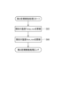
図5は、実施形態の画像形成システム100において実行される契約処理S1および解約処理S2を示す図である。契約処理S1は、通常ユーザが供給者と契約を締結する際に行われる処理である。契約処理S1は、契約ユーザの画像形成装置1の動作モードを、通常モードから契約モードに変更する処理を含む。解約処理S2は、契約ユーザが契約を解除する際に行われる処理である。解約処理S2は、契約ユーザの画像形成装置1の動作モードを、契約モードから通常モードに変更する処理を含む。以下、契約処理S1および解約処理S2について、順に説明する。
<Example of image formation system operation>
5 is a diagram showing contract processing S1 and cancellation processing S2 executed in the image forming system 100 of the embodiment. Contract processing S1 is processing performed when a normal user concludes a contract with a supplier. Contract processing S1 includes processing for changing the operation mode of the image forming device 1 of the contracted user from normal mode to contract mode. Cancellation processing S2 is processing performed when the contracted user cancels the contract. Cancellation processing S2 includes processing for changing the operation mode of the image forming device 1 of the contracted user from contract mode to normal mode. Contract processing S1 and cancellation processing S2 will be described in order below.

<契約処理>
契約処理S1では、まず、登録装置8が、契約要求Rq1をサーバ7へ送信する(契約要求送信処理S11)。契約要求Rq1には、契約を希望するユーザに関する情報(ユーザの氏名や住所等を含む)と、課金額など契約に関する情報とが含まれ得る。また、契約要求Rq1には、支払いに関する情報と、ユーザが使用する画像形成装置1を識別するためのデバイス情報(デバイスID)とが含まれ得る。なお、登録装置8が契約要求送信処理S11を行うことは必須ではない。例えば、画像形成装置1においてユーザが所定の操作を行うことにより、画像形成装置1が契約要求Rq1をサーバ7へ送信してもよい。
<Contract Processing>
In the contract process S1, first, the registration device 8 transmits a contract request Rq1 to the server 7 (contract request transmission process S11). The contract request Rq1 may include information about the user who desires to enter into a contract (including the user's name, address, etc.) and information about the contract, such as the amount charged. The contract request Rq1 may also include information about payment and device information (device ID) for identifying the image forming device 1 used by the user. It is not essential that the registration device 8 performs the contract request transmission process S11. For example, the image forming device 1 may transmit the contract request Rq1 to the server 7 by the user performing a predetermined operation on the image forming device 1.

サーバ7は、受信した契約要求Rq1に基づいて、契約を要求された画像形成装置1に、変更命令Rs1を送信する(変更命令送信処理S12)。変更命令Rs1は、対象の画像形成装置1が備える制御部51に対する命令であって、制御部51の動作モードを契約モードに設定させる命令である。制御部51は、変更命令Rs1を受信すると、動作モードを契約モードに設定する(動作モード設定処理S13)。 Based on the received contract request Rq1, the server 7 transmits a change command Rs1 to the image forming device 1 for which a contract has been requested (change command transmission process S12). The change command Rs1 is a command to the control unit 51 provided in the target image forming device 1, and is a command to set the operation mode of the control unit 51 to the contract mode. When the control unit 51 receives the change command Rs1, it sets the operation mode to the contract mode (operation mode setting process S13).

<解約処理>
解約処理S2では、まず、登録装置8が、解約要求Rq2をサーバ7へ送信する(解約要求送信処理S21)。解約要求Rq2には、解約を希望するユーザに関する情報が含まれ得る。なお、登録装置8が解約要求送信処理S21を行うことは必須ではない。例えば、画像形成装置1においてユーザが所定の操作を行うことにより、画像形成装置1が解約要求Rq2をサーバ7へ送信してもよい。
<Cancellation process>
In the cancellation process S2, first, the registration device 8 transmits a cancellation request Rq2 to the server 7 (cancellation request transmission process S21). The cancellation request Rq2 may include information about the user who wishes to cancel. It is not essential that the registration device 8 performs the cancellation request transmission process S21. For example, the image forming device 1 may transmit the cancellation request Rq2 to the server 7 by a user performing a predetermined operation on the image forming device 1.

サーバ7は、受信した解約要求Rq2に基づいて、解約を要求された画像形成装置1に、変更命令Rs2を送信する(変更命令送信処理S22)。変更命令Rs2は、対象の画像形成装置1が備える制御部51に対する命令であって、制御部51の動作モードを通常モードに設定させる命令である。制御部51は、変更命令Rs2を受信すると、動作モードを通常モードに設定する(動作モード設定処理S23)。 Based on the received cancellation request Rq2, the server 7 transmits a change command Rs2 to the image forming device 1 for which cancellation has been requested (change command transmission process S22). The change command Rs2 is a command to the control unit 51 provided in the target image forming device 1, and is a command to set the operation mode of the control unit 51 to normal mode. When the control unit 51 receives the change command Rs2, it sets the operation mode to normal mode (operation mode setting process S23).

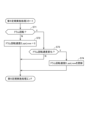
図6は、画像形成装置1の制御部51が実行するドラムチェック処理の流れを示す図である。ドラムチェック処理は、ドラムカートリッジ20が交換された際に実行される処理である。 Figure 6 is a diagram showing the flow of the drum check process executed by the control unit 51 of the image forming device 1. The drum check process is executed when the drum cartridge 20 is replaced.

制御部51は、ドラムチェック処理を開始すると、ドラムカートリッジ20が交換されたかを判定する(交換判定処理S31)。交換判定処理S31において、画像形成装置1の電源がONからOFFに切り換えられた場合、または、カバー11が開位置から閉位置へ移動したことを開閉センサ12が検出した場合、制御部51はドラムカートリッジ20のドラムIDと、本体メモリ513が予め記憶しているドラムIDとを比較する。制御部51は、ドラムIDが一致した場合、ドラムカートリッジ20が交換されていないと判定する。制御部51は、ドラムIDが一致しなかった場合、ドラムカートリッジ20が交換されたと判定する。 When the control unit 51 starts the drum check process, it determines whether the drum cartridge 20 has been replaced (replacement determination process S31). In the replacement determination process S31, when the power of the image forming device 1 is switched from ON to OFF, or when the opening/closing sensor 12 detects that the cover 11 has moved from the open position to the closed position, the control unit 51 compares the drum ID of the drum cartridge 20 with the drum ID previously stored in the main body memory 513. When the drum IDs match, the control unit 51 determines that the drum cartridge 20 has not been replaced. When the drum IDs do not match, the control unit 51 determines that the drum cartridge 20 has been replaced.

制御部51は、交換判定処理S31によってドラムカートリッジ20が交換されたと判定した場合(Yes)、ドラム情報ラッチ処理S32を実行する。ドラム情報ラッチ処理S32において、制御部51は、ドラムメモリ22が記憶している各種情報を読み出して本体メモリ513に書き込む。 When the control unit 51 determines that the drum cartridge 20 has been replaced by the replacement determination process S31 (Yes), it executes the drum information latch process S32. In the drum information latch process S32, the control unit 51 reads out various information stored in the drum memory 22 and writes it to the main body memory 513.

図7は、ドラム情報ラッチ処理S32の詳細な流れを示す図である。図7に示すように、ドラム情報ラッチ処理S32は、ドラム寿命情報の読み出しおよび書き込み(読み書き処理S41)、ドラム種別情報の読み出しおよび書き込み(読み書き処理S42)、ドラム履歴情報の読み出し及び書き込み(読み書き処理S43)、発注済フラグの読み出し及び書き込み処理(読み書き処理S44)、及び、付着量情報の読み出し及び書き込み(読み書き処理S45)を含む。 Figure 7 is a diagram showing a detailed flow of the drum information latch process S32. As shown in Figure 7, the drum information latch process S32 includes reading and writing drum life information (read and write process S41), reading and writing drum type information (read and write process S42), reading and writing drum history information (read and write process S43), reading and writing the order completion flag (read and write process S44), and reading and writing adhesion amount information (read and write process S45).

制御部51は、読み書き処理S41において、ドラムメモリ22から読み出したドラム寿命情報が表す累積印刷枚数、及び、累積ドラム回転数を、ドラム情報として本体メモリ513に記憶させる。制御部51は、読み書き処理S42において、ドラムメモリ22から読み出したドラム種別情報を、ドラム情報として本体メモリ513に記憶させる。制御部51は、読み書き処理S43において、ドラムメモリ22から読み出したドラム履歴情報が表す放電前検出回数、及び、放電検出回数を、ドラム情報として本体メモリ513に記憶させる。制御部51は、読み書き処理S45において、付着量情報をドラムメモリ22から読み出し、ドラム情報として本体メモリ513に記憶させる。付着量情報は、感光体ドラム21に対するシリカの付着量Yを表す情報である。 In the read/write process S41, the control unit 51 stores the cumulative number of printed sheets and the cumulative number of drum rotations represented by the drum life information read from the drum memory 22 in the main memory 513 as drum information. In the read/write process S42, the control unit 51 stores the drum type information read from the drum memory 22 in the main memory 513 as drum information. In the read/write process S43, the control unit 51 stores the number of pre-discharge detections and the number of discharge detections represented by the drum history information read from the drum memory 22 in the main memory 513 as drum information. In the read/write process S45, the control unit 51 reads the adhesion amount information from the drum memory 22 and stores it in the main memory 513 as drum information. The adhesion amount information is information that represents the adhesion amount Y of silica on the photosensitive drum 21.

図6に示すように、制御部51は、ドラム情報ラッチ処理S32を実行した後、ドラムカートリッジ20が使用可能であるかを判定する(判定処理S33)。制御部51は、判定処理S33の結果に応じて、エラー処理S36、または、ドラム寿命チェック処理S37を実行する。 As shown in FIG. 6, after executing the drum information latch process S32, the control unit 51 determines whether the drum cartridge 20 is usable (determination process S33). Depending on the result of the determination process S33, the control unit 51 executes the error process S36 or the drum life check process S37.

図8は、ドラムカートリッジ20の種別と、制御部51の動作モードとの対応関係を示す図である。図8に示すように、制御部51の動作モードが通常モードである場合、制御部51は、通常ドラムカートリッジ20の使用を許可するが、契約ドラムカートリッジ20の使用を制限する。制御部51の動作モードが契約モードである場合、制御部51は、通常ドラムカートリッジ20および契約ドラムカートリッジ20のいずれについても、使用を許可する。 Figure 8 is a diagram showing the correspondence between the type of drum cartridge 20 and the operating mode of the control unit 51. As shown in Figure 8, when the operating mode of the control unit 51 is the normal mode, the control unit 51 allows the use of normal drum cartridges 20 but restricts the use of contract drum cartridges 20. When the operating mode of the control unit 51 is the contract mode, the control unit 51 allows the use of both normal drum cartridges 20 and contract drum cartridges 20.

図6に戻って、制御部51は、判定処理S33によって、ドラムカートリッジ20の使用を許可できないと判定した場合(No)、エラー処理S36を実行する。制御部51は、エラー処理S36において、ドラムカートリッジ20の使用を禁止することを表す使用不可フラグを本体メモリ513に記憶させてもよい。また、制御部51は、エラー処理S36において、通常ドラムカートリッジ20への交換を要求する表示情報をディスプレイ55に表示させてもよい。制御部51は、エラー処理S36を実行した後、ドラムチェック処理を終了する。 Returning to FIG. 6, if the control unit 51 determines in the determination process S33 that the use of the drum cartridge 20 cannot be permitted (No), it executes the error process S36. In the error process S36, the control unit 51 may store an unusable flag indicating that the use of the drum cartridge 20 is prohibited in the main body memory 513. In the error process S36, the control unit 51 may also display information on the display 55 requesting replacement with a normal drum cartridge 20. After executing the error process S36, the control unit 51 ends the drum check process.

制御部51は、判定処理S33によって、ドラムカートリッジ20の使用を許可できると判定した場合(Yes)、ドラム寿命チェック処理S37を実行する。制御部51は、ドラム寿命チェック処理S37において、ドラム情報ラッチ処理S32によって本体メモリ513に記憶させたドラム履歴情報、ドラム寿命情報、及び付着量情報をチェックする。 When the control unit 51 determines in the determination process S33 that the use of the drum cartridge 20 can be permitted (Yes), it executes the drum life check process S37. In the drum life check process S37, the control unit 51 checks the drum history information, drum life information, and adhesion amount information stored in the main body memory 513 by the drum information latch process S32.

<ドラム寿命チェック処理>
図9は、図6に示すドラム寿命チェック処理S37の詳細を示す図である。制御部51は、ドラム寿命チェック処理S37を開始すると、本体メモリ513が記憶しているドラム履歴情報に基づいて、ドラムカートリッジ20が交換すべき状態(以下、「要交換状態」と称する。)であるかを判定する(判定処理S51)。判定処理S51において、制御部51は、ドラム履歴情報が表す「放電前検出回数」が要交換状態を表す閾値Th_1eを越えるかを判定するとともに、ドラム履歴情報が表す「放電検出回数」が要交換状態を表す閾値Th_2eを越えるかを判定する。なお、判定処理S51において、制御部51は、少なくとも、ドラム履歴情報が表す「放電検出回数」が要交換状態を表す閾値Th_2eを越えるか、を判定していればよい。または、判定処理S51において、制御部51は、ドラム履歴情報が表す「放電前検出回数」が要交換状態を表す閾値Th_1eを越えるか、または、ドラム履歴情報が表す「放電検出回数」が要交換状態を表す閾値Th_2eを越えるか、のいずれかを判定すればよい。
<Drum life check process>
9 is a diagram showing details of the drum life check process S37 shown in FIG. 6. When the control unit 51 starts the drum life check process S37, it judges whether the drum cartridge 20 is in a state that needs to be replaced (hereinafter referred to as a "replacement required state") based on the drum history information stored in the main body memory 513 (judgment process S51). In the judgment process S51, the control unit 51 judges whether the "pre-discharge detection count" represented by the drum history information exceeds a threshold value Th_1e indicating a replacement required state, and judges whether the "discharge detection count" represented by the drum history information exceeds a threshold value Th_2e indicating a replacement required state. In the judgment process S51, the control unit 51 only needs to judge whether the "discharge detection count" represented by the drum history information exceeds a threshold value Th_2e indicating a replacement required state. Alternatively, in the judgment process S51, the control unit 51 may determine either whether the “number of pre-discharge detections” represented by the drum history information exceeds a threshold value Th_1e indicating a state requiring replacement, or whether the “number of discharge detections” represented by the drum history information exceeds a threshold value Th_2e indicating a state requiring replacement.

なお、制御部51は、ある数値データについて閾値を用いて判定を行う場合、その数値データが閾値以上であるかを判定するようにしてもよい。例えば、制御部51は、判定処理S51において、ドラム履歴情報が表す放電前検出回数が所定の閾値以上となるかを判定するようにしてもよい。また、制御部51は、判定処理S51において、ドラム履歴情報が表す放電検出回数が所定の閾値以上となるかを判定するようにしてもよい。 When the control unit 51 makes a judgment using a threshold value for certain numerical data, the control unit 51 may determine whether the numerical data is equal to or greater than the threshold value. For example, in the judgment process S51, the control unit 51 may determine whether the number of pre-discharge detections represented by the drum history information is equal to or greater than a predetermined threshold value. Also, in the judgment process S51, the control unit 51 may determine whether the number of discharge detections represented by the drum history information is equal to or greater than a predetermined threshold value.

判定処理S51によって、放電前検出回数が閾値Th_1eを越えると制御部51が判定した場合、または、放電検出回数が閾値Th_2eを越えると制御部51が判定した場合(判定処理S51においてYes)、ドラムカートリッジ20が要交換状態であるとして、制御部51は後述する表示処理S54を実行する。なお、制御部51は、判定処理S51によって、放電検出回数が閾値Th_2eを越えると判定した後、さらに、帯電ワイヤ231の電圧値を測定してもよい。そして、制御部51は、測定された帯電ワイヤ231の電圧値が所定の電圧値より低い(または、測定された帯電ワイヤ231の電圧値が異常値である)と判定した場合、表示処理S54を実行してもよい。判定処理S51によって、放電前検出回数が閾値Th_1eを越えず、かつ、放電検出回数が閾値Th_2eを越えないと制御部51が判定した場合(判定処理S51においてNo)、制御部51は判定処理S52を実行する。 When the control unit 51 determines that the pre-discharge detection count exceeds the threshold value Th_1e or the control unit 51 determines that the discharge detection count exceeds the threshold value Th_2e (Yes in the determination process S51), the control unit 51 determines that the drum cartridge 20 needs to be replaced and executes the display process S54 described later. Note that the control unit 51 may further measure the voltage value of the charged wire 231 after determining that the discharge detection count exceeds the threshold value Th_2e in the determination process S51. Then, when the control unit 51 determines that the measured voltage value of the charged wire 231 is lower than a predetermined voltage value (or that the measured voltage value of the charged wire 231 is an abnormal value), it may execute the display process S54. When the control unit 51 determines that the pre-discharge detection count does not exceed the threshold value Th_1e and the discharge detection count does not exceed the threshold value Th_2e in the determination process S51 (No in the determination process S51), the control unit 51 executes the determination process S52.

制御部51は、判定処理S52において、本体メモリ513が記憶しているドラム寿命情報に基づいて、ドラムカートリッジ20が要交換状態であるかを判定する。判定処理S52において、制御部51は、ドラム寿命情報の「累積印刷枚数」が要交換状態を表す閾値Th_3eを越えるかを判定するとともに、ドラム寿命情報の「累積ドラム回転数」が要交換状態を表す閾値Th_4eを越えるかを判定する。判定処理S52によって、累積印刷枚数が閾値Th_3eを越えると制御部51が判定した場合、または、累積ドラム回転数が閾値Th_4eを越えると制御部51が判定した場合(判定処理S52においてYes)、制御部51は表示処理S54を実行する。判定処理S52において、累積印刷枚数が閾値Th_3eを越えず、かつ、累積ドラム回転数が閾値Th_4eを越えないと制御部51が判定した場合(判定処理S52においてNo)、制御部51は判定処理S53を実行する。 In the judgment process S52, the control unit 51 judges whether the drum cartridge 20 needs to be replaced based on the drum life information stored in the main memory 513. In the judgment process S52, the control unit 51 judges whether the "cumulative number of printed sheets" in the drum life information exceeds the threshold Th_3e indicating a replacement state, and judges whether the "cumulative drum rotation count" in the drum life information exceeds the threshold Th_4e indicating a replacement state. If the control unit 51 judges that the cumulative number of printed sheets exceeds the threshold Th_3e or that the cumulative drum rotation count exceeds the threshold Th_4e by the judgment process S52 (Yes in the judgment process S52), the control unit 51 executes the display process S54. In the judgment process S52, if the control unit 51 judges that the cumulative number of printed sheets does not exceed the threshold Th_3e and that the cumulative drum rotation count does not exceed the threshold Th_4e (No in the judgment process S52), the control unit 51 executes the judgment process S53.

制御部51は、判定処理S53において、本体メモリ513が記憶している付着量情報に基づいて、ドラムカートリッジ20が要交換状態であるかを判定する。判定処理S53において、制御部51は、付着量情報の「付着量Y」が要交換状態を表す閾値Th_5e(第1閾値)を越えるかを判定する。制御部51は、判定処理S53によって、付着量Yが閾値Th_5eを越えると判定した場合(Yes)、制御部51は、表示処理S54を実行する。 In the determination process S53, the control unit 51 determines whether the drum cartridge 20 needs to be replaced based on the adhesion amount information stored in the main body memory 513. In the determination process S53, the control unit 51 determines whether the "adhesion amount Y" of the adhesion amount information exceeds a threshold value Th_5e (first threshold value) indicating a replacement required state. If the control unit 51 determines by the determination process S53 that the adhesion amount Y exceeds the threshold value Th_5e (Yes), the control unit 51 executes the display process S54.

制御部51は、表示処理S54において、ドラムカートリッジ20の交換を促す画像(例えば、「Replace Drum」の文字を含む画像)をディスプレイ55に表示させる。制御部51は、表示処理S54を実行した後、ドラム寿命チェック処理を終了する。 In display process S54, the control unit 51 causes the display 55 to display an image (e.g., an image including the words "Replace Drum") that prompts the user to replace the drum cartridge 20. After executing display process S54, the control unit 51 ends the drum life check process.

表示処理S54は、ドラムカートリッジ20の使用を制限する使用制限処理の一例である。なお、制御部51は、判定処理S53によって、シリカの付着量Yが閾値Th_5eを越えたと判定した場合、画像形成装置1において、ドラムカートリッジ20の使用を禁止してもよい。 The display process S54 is an example of a usage restriction process that restricts the use of the drum cartridge 20. Note that, if the control unit 51 determines by the determination process S53 that the amount Y of silica adhesion exceeds the threshold value Th_5e, the control unit 51 may prohibit the use of the drum cartridge 20 in the image forming device 1.

制御部51は、判定処理S53によって、付着量Yが閾値Th_5eを越えないと判定した場合(No)、ドラム寿命情報に基づき、ドラムカートリッジ20が要発注状態であるかを判定する(判定処理S55)。要発注状態とは、ドラムカートリッジ20が要交換状態になるよりも前の状態であって、新たなドラムカートリッジ20を発注すべき状態をいう。要発注状態は、具体的には、残りの寿命が少なくなった状態、あるいは、故障等のトラブルが発生し易い状態である。 When the control unit 51 determines in the determination process S53 that the adhesion amount Y does not exceed the threshold value Th_5e (No), it determines whether the drum cartridge 20 is in an order-required state based on the drum life information (determination process S55). The order-required state refers to a state before the drum cartridge 20 requires replacement, in which a new drum cartridge 20 should be ordered. Specifically, the order-required state refers to a state in which the remaining life is short, or a state in which a problem such as a breakdown is likely to occur.

判定処理S55において、制御部51は、ドラム寿命情報の「累積印刷枚数」が要発注状態を表す所定の閾値Th_3を越えるか、及び、ドラム寿命情報の「累積ドラム回転数」が要発注状態を表す閾値Th_4を越えるかを判定する。累積印刷枚数が閾値Th_3を越えず、かつ、累積ドラム回転数が閾値Th_4を越えないと制御部51が判定した場合(判定処理S55においてNo)、制御部51は判定処理S56を実行する。また、累積印刷枚数が閾値Th_3を越えると制御部51が判定した場合、または、累積ドラム回転数が閾値Th_4を越えると制御部51が判定した場合(判定処理S55においてYes)、制御部51は後述する表示処理S57を実行する。 In the judgment process S55, the control unit 51 judges whether the "cumulative number of printed sheets" of the drum life information exceeds a predetermined threshold Th_3 indicating an order required state, and whether the "cumulative drum rotation count" of the drum life information exceeds a threshold Th_4 indicating an order required state. If the control unit 51 judges that the cumulative number of printed sheets does not exceed the threshold Th_3 and that the cumulative drum rotation count does not exceed the threshold Th_4 (No in the judgment process S55), the control unit 51 executes the judgment process S56. If the control unit 51 judges that the cumulative number of printed sheets exceeds the threshold Th_3 or that the cumulative drum rotation count exceeds the threshold Th_4 (Yes in the judgment process S55), the control unit 51 executes the display process S57 described later.

判定処理S56において、制御部51は、付着量情報に基づいて、ドラムカートリッジ20が要発注状態であるかを判定する処理である。具体的には、制御部51は、付着量情報の「付着量Y」が要発注状態を表す閾値Th_5を越えるかを判定する。制御部51は、付着量Yが閾値Th_5を越えると制御部51が判定した場合(判定処理S56においてYes)、表示処理S57を実行する。制御部51は、付着量Yが閾値Th_5を越えないと判定した場合(判定処理S56においてNo)、ドラム寿命チェック処理を終了する。 In the judgment process S56, the control unit 51 judges whether the drum cartridge 20 is in an order-required state based on the adhesion amount information. Specifically, the control unit 51 judges whether the "adhesion amount Y" of the adhesion amount information exceeds the threshold value Th_5, which indicates an order-required state. If the control unit 51 judges that the adhesion amount Y exceeds the threshold value Th_5 (Yes in the judgment process S56), the control unit 51 executes the display process S57. If the control unit 51 judges that the adhesion amount Y does not exceed the threshold value Th_5 (No in the judgment process S56), the control unit 51 ends the drum life check process.

表示処理S57において、制御部51は、ドラムカートリッジ20が要発注状態であることを表す画面(例えば、「Drum End Soon」の文字を含む画像)をディスプレイ55に表示させる。制御部51は、表示処理S57を実行した後、本体筐体10に装着されているドラムカートリッジ20のドラム種別情報が契約型であるかを判定する(判定処理S571)。制御部51は、ドラム種別情報が契約型ではないと判定した場合(判定処理S571においてNo)、ドラム寿命チェック処理を終了する。 In display process S57, the control unit 51 causes the display 55 to display a screen indicating that the drum cartridge 20 is in an order-required state (for example, an image including the words "Drum End Soon"). After executing display process S57, the control unit 51 determines whether the drum type information of the drum cartridge 20 attached to the main body housing 10 is a contract type (determination process S571). If the control unit 51 determines that the drum type information is not a contract type (No in determination process S571), it ends the drum life check process.

制御部51は、ドラム種別情報が契約型であると判定した場合(判定処理S571においてYes)、新たな契約ドラムカートリッジ20が未発注であるかを判定する。具体的には、制御部51は、本体メモリ513に記憶されている発注済フラグに基づいて判定する(発注判定処理S58)。発注済フラグは、発注済であるかを表す情報であり、本体メモリ513がドラム情報として記憶する情報である。制御部51は、発注判定処理S58によって、未発注であると判定した場合、注文情報送信処理S59を実行する。制御部51は、発注判定処理S58によって、発注済みであると判定した場合、ドラム寿命チェック処理を終了する。 When the control unit 51 determines that the drum type information is a contract type (Yes in the determination process S571), it determines whether a new contract drum cartridge 20 has not been ordered. Specifically, the control unit 51 makes this determination based on the order flag stored in the main body memory 513 (order determination process S58). The order flag is information indicating whether an order has been placed, and is information stored in the main body memory 513 as drum information. When the control unit 51 determines that an order has not been placed through the order determination process S58, it executes the order information transmission process S59. When the control unit 51 determines that an order has been placed through the order determination process S58, it ends the drum life check process.

注文情報送信処理S59は、制御部51が、サーバ7に新たな契約ドラムカートリッジ20を注文するための注文情報を送信する処理である。注文情報は、例えば、新たな契約ドラムカートリッジ20を要求することを表す情報と、画像形成装置1のデバイス情報とを含む。図5に示すように、サーバ7は、注文情報を受信すると、発送業者のサーバ9に対して、発注情報を送信する(発注処理S751)。発注情報は、具体的には、注文情報に対応する契約ユーザの氏名や住所などの情報を含む。発送業者は、発注情報に基づき、契約ユーザに対して、契約ドラムカートリッジ20を発送する(発送処理S752)。これにより、契約ユーザは、契約ドラムカートリッジ20を受け取ることができるため、本体筐体10に装着されているドラムカートリッジ20が要交換状態となった場合に、契約ドラムカートリッジ20に交換できる。 The order information transmission process S59 is a process in which the control unit 51 transmits order information for ordering a new contract drum cartridge 20 to the server 7. The order information includes, for example, information indicating that a new contract drum cartridge 20 is requested and device information of the image forming device 1. As shown in FIG. 5, when the server 7 receives the order information, it transmits the order information to the server 9 of the shipping company (ordering process S751). The order information specifically includes information such as the name and address of the contract user corresponding to the order information. The shipping company dispatches the contract drum cartridge 20 to the contract user based on the order information (shipping process S752). This allows the contract user to receive the contract drum cartridge 20, so that when the drum cartridge 20 attached to the main body housing 10 needs to be replaced, it can be replaced with the contract drum cartridge 20.

なお、注文情報送信処理S59は、制御部51が、注文情報を送信する承認を受けたかを判定する承認判定処理を含んでいてもよい。具体的には、制御部51が、ディスプレイ55に承認を求める画像を表示することによって、ユーザに対して承認の入力を要求してもよい。そして、制御部51は、ユーザが承認する入力を受け付けた場合に、承認を受けたと判定し、注文情報を送信してもよい。これにより、ユーザの承認なしに、自動的に注文情報がサーバ7へ送信されることを抑制できる。 The order information transmission process S59 may include an approval determination process in which the control unit 51 determines whether approval to transmit the order information has been received. Specifically, the control unit 51 may request the user to input approval by displaying an image requesting approval on the display 55. Then, when the control unit 51 receives an input of approval from the user, it may determine that approval has been received and transmit the order information. This makes it possible to prevent the order information from being automatically transmitted to the server 7 without the user's approval.

図9に戻って、制御部51は、注文情報送信処理S59を実行した後、フラグ処理S591を実行する。フラグ処理S591は、発注済フラグを本体メモリ513及びドラムメモリ22に保存する処理である。制御部51は、フラグ処理S591を実行した後、ドラム寿命チェック処理を終了する。 Returning to FIG. 9, after executing the order information transmission process S59, the control unit 51 executes the flag process S591. The flag process S591 is a process for saving an order completion flag in the main body memory 513 and the drum memory 22. After executing the flag process S591, the control unit 51 ends the drum life check process.

図9に示す例では、画像形成装置1の制御部51が、判定処理S55または判定処理S56を実行することによってドラムカートリッジ20が要発注状態となったかを判定する。そして、制御部51が、ドラムカートリッジ20が要発注状態となったと判定した場合にサーバ7に対して新たなドラムカートリッジ20を発注するようにしている。しかしながら、サーバ7が、判定処理S55または判定処理S56を行うことによって、新たなドラムカートリッジ20を発注するか否かを判断するようにしてもよい。例えば、画像形成装置1がサーバ7に対して、ドラム寿命情報、または、付着量情報を送信してもよい。そして、サーバ7が、ドラム寿命情報と閾値Th_3,Th_4とを比較する処理(判定処理S55に対応する処理)、または、付着量情報と閾値Th_5とを比較する処理(判定処理S56に対応する処理)を行うことによって、新たなドラムカートリッジ20を発注するかを決定してもよい。 9, the control unit 51 of the image forming device 1 executes the judgment process S55 or S56 to judge whether the drum cartridge 20 is in an order-required state. If the control unit 51 judges that the drum cartridge 20 is in an order-required state, a new drum cartridge 20 is ordered from the server 7. However, the server 7 may execute the judgment process S55 or S56 to judge whether to order a new drum cartridge 20. For example, the image forming device 1 may transmit drum life information or adhesion amount information to the server 7. The server 7 may then execute a process of comparing the drum life information with thresholds Th_3 and Th_4 (processing corresponding to the judgment process S55) or a process of comparing the adhesion amount information with a threshold Th_5 (processing corresponding to the judgment process S56) to determine whether to order a new drum cartridge 20.

図6に戻って、制御部51は、ドラム寿命チェック処理S37を実行した後、動作要求待ち処理S38を実行する。動作要求待ち処理S38は、画像形成装置1を“Ready”(動作要求待ち)の状態とする処理である。すなわち、制御部51は、画像形成装置1を印刷要求待ちの状態にして、画像形成装置1を待機させる。 Returning to FIG. 6, after executing the drum life check process S37, the control unit 51 executes the operation request waiting process S38. The operation request waiting process S38 is a process for putting the image forming device 1 into a "Ready" state (waiting for an operation request). In other words, the control unit 51 puts the image forming device 1 into a state waiting for a print request, and keeps the image forming device 1 on standby.

図10~図20に示すように、画像形成装置1は、第1~第8定期実施処理を実行する。第1~第8定期処理は、制御部51が、定期的または所定のイベントが発生するごとに実行する処理である。以下、第1~第8定期実施処理を順に説明する。 As shown in Figures 10 to 20, the image forming device 1 executes the first to eighth periodic execution processes. The first to eighth periodic execution processes are processes that the control unit 51 executes periodically or whenever a specified event occurs. The first to eighth periodic execution processes are described below in order.

<第1定期実施処理>
図10は、制御部51が実行する第1定期実施処理の流れを示す図である。第1定期実施処理は、制御部51が、本体メモリ513が記憶しているドラム寿命情報に基づいて、ドラムメモリ22が記憶しているドラム寿命情報を更新する処理である。制御部51は、第1定期実施処理を開始すると、本体メモリ513が記憶しているドラム寿命情報のうち、累積印刷枚数が増加したかを判定する(判定処理S61)。制御部51は、累積印刷枚数が増加したと判定した場合(判定処理S61においてYes)、本体メモリ513が記憶している累積印刷枚数をドラムメモリ22に書き込む(書き込み処理S62)。
<First periodic implementation process>
10 is a diagram showing the flow of the first periodic execution process executed by the control unit 51. The first periodic execution process is a process in which the control unit 51 updates the drum life information stored in the drum memory 22 based on the drum life information stored in the main memory 513. When the control unit 51 starts the first periodic execution process, it determines whether the cumulative number of printed sheets has increased from the drum life information stored in the main memory 513 (determination process S61). If the control unit 51 determines that the cumulative number of printed sheets has increased (Yes in determination process S61), it writes the cumulative number of printed sheets stored in the main memory 513 to the drum memory 22 (write process S62).

制御部51は、判定処理S61を実行した後、本体メモリ513が記憶しているドラム寿命情報のうち、累積ドラム回転数が増加したかを判定する(判定処理S63)。制御部51は、累積ドラム回転数が増加したと判定した場合(判定処理S63においてYes)、本体メモリ513が記憶している累積ドラム回転数をドラムメモリ22に書き込む(書き込み処理S64)。制御部51は、判定処理S63を実行した後、第1定期実施処理を終了する。 After executing the determination process S61, the control unit 51 determines whether the cumulative drum rotation count has increased from the drum life information stored in the main memory 513 (determination process S63). If the control unit 51 determines that the cumulative drum rotation count has increased (Yes in the determination process S63), it writes the cumulative drum rotation count stored in the main memory 513 to the drum memory 22 (write process S64). After executing the determination process S63, the control unit 51 ends the first periodic implementation process.

<第2定期実施処理>
図11は、制御部51が実行する第2定期実施処理の流れを示す図である。第2定期処理は、本体メモリ513が記憶している温度Tmep_nowおよび湿度Hum_nowを更新する処理である。温度Temp_nowは、本体筐体10内の現在温度を表す。湿度Hum_nowは、本体筐体10内の現在湿度を表す。制御部51は、第2定期実施処理を開始すると、温度センサ17の出力に基づいて、本体メモリ513が記憶している温度Temp_nowを更新する(温度更新処理S65)。また、制御部51は、温度更新処理S65を実行した後、湿度Hum_nowを更新する(湿度更新処理S66)。制御部51は、湿度更新処理S66を実行した後、第2定期更新処理を終了する。
<Second regular implementation process>
FIG. 11 is a diagram showing the flow of the second periodic execution process executed by the control unit 51. The second periodic process is a process for updating the temperature Tmep_now and humidity Hum_now stored in the main body memory 513. The temperature Temp_now represents the current temperature inside the main body housing 10. The humidity Hum_now represents the current humidity inside the main body housing 10. When the control unit 51 starts the second periodic execution process, it updates the temperature Temp_now stored in the main body memory 513 based on the output of the temperature sensor 17 (temperature update process S65). After executing the temperature update process S65, the control unit 51 also updates the humidity Hum_now (humidity update process S66). After executing the humidity update process S66, the control unit 51 ends the second periodic update process.

<第3定期実施処理>
図12は、制御部51が実行する第3定期実施処理の流れを示す図である。第3定期実施処理は、本体メモリ513が記憶しているグリッドバイアス値GBias_nowを更新する処理である。グリッドバイアス値GBias_nowは、現在の帯電器23が感光体ドラム21に印加する電圧の大きさを表す情報であり、具体的には、グリッド233に印加されている電圧値である。制御部51は、第3定期実施処理を開始すると、本体メモリ513が記憶しているグリッドバイアス値GBias_nowを更新する(更新処理S67)。制御部51は、更新処理S67を実行した後、第3定期実施処理を終了する。
<Third regular implementation process>
12 is a diagram showing the flow of the third periodic execution process executed by the control unit 51. The third periodic execution process is a process for updating the grid bias value GBias_now stored in the main body memory 513. The grid bias value GBias_now is information representing the magnitude of the voltage currently applied by the charger 23 to the photoconductor drum 21, and specifically, is the voltage value applied to the grid 233. When the control unit 51 starts the third periodic execution process, it updates the grid bias value GBias_now stored in the main body memory 513 (update process S67). After executing the update process S67, the control unit 51 ends the third periodic execution process.

<第4定期実施処理>
図13は、制御部51が実行する第4定期実施処理の流れを示す図である。第4定期処理は、本体メモリ513が記憶しているイレースランプ状態Elamp_nowを更新する処理である。イレースランプ状態Elamp_nowは、現在のイレースランプ26の点灯状態を表す情報であって、イレースランプ26が、点灯しているかまたは消灯しているかのどちらかを表す情報である。制御部51は、第4定期実施処理を開始すると、本体メモリ513が記憶しているイレースランプ状態Elamp_nowを更新する(更新処理S68)。制御部51は、更新処理S68を実行した後、第4定期実施処理を終了する。
<Fourth regular implementation process>
FIG. 13 is a diagram showing the flow of the fourth periodic execution process executed by the control unit 51. The fourth periodic process is a process for updating the erase lamp state Elamp_now stored in the main body memory 513. The erase lamp state Elamp_now is information representing the current lighting state of the erase lamp 26, and is information representing whether the erase lamp 26 is on or off. When the control unit 51 starts the fourth periodic execution process, it updates the erase lamp state Elamp_now stored in the main body memory 513 (update process S68). After executing the update process S68, the control unit 51 ends the fourth periodic execution process.

<第5定期実施処理>
図14は、制御部51が実行する第5定期実施処理の流れを示す図である。第5定期実施処理は、本体メモリ513が記憶しているドラム回転速度D_spd_nowを更新する処理である。ドラム回転速度D_spd_nowは、現在の感光体ドラム21の回転速度を表す情報である。制御部51は、第5定期処理を開始すると、感光体ドラム21が回転しているかを判定する(判定処理S71)。制御部51は、感光体ドラム21が回転していないと判定した場合(判定処理S71においてNo)、本体メモリ513に記憶されているドラム回転速度D_spd_nowを0とする。制御部51は、感光体ドラム21が回転していると判定した場合(判定処理S71においてYes)、感光体ドラム21の回転速度が変化したかを判定する(判定処理S73)。制御部51は、判定処理S73において、現在の感光体ドラム21の回転速度が、本体メモリ513が記憶しているドラム回転速度D_spd_nowと異なる場合、感光体ドラム21の回転速度が変化したと判定する。制御部51は、ドラム回転速度D_spd_nowが変化していないと判定した場合(判定処理S73においてNo)、第5定期実施処理を終了する。制御部51は、ドラム回転速度D_spd_nowが変化したと判定した場合(判定処理S73においてYes)、感光体ドラム21は、回転速度D_spd_nowを更新する(更新処理S74)。制御部51は、判定処理S73を実行した後、第5定期実施処理を終了する。
<5th regular implementation process>
FIG. 14 is a diagram showing the flow of the fifth periodic execution process executed by the control unit 51. The fifth periodic execution process is a process for updating the drum rotation speed D_spd_now stored in the main body memory 513. The drum rotation speed D_spd_now is information representing the current rotation speed of the photosensitive drum 21. When the control unit 51 starts the fifth periodic process, it judges whether the photosensitive drum 21 is rotating (judgment process S71). When the control unit 51 judges that the photosensitive drum 21 is not rotating (No in the judgment process S71), it sets the drum rotation speed D_spd_now stored in the main body memory 513 to 0. When the control unit 51 judges that the photosensitive drum 21 is rotating (Yes in the judgment process S71), it judges whether the rotation speed of the photosensitive drum 21 has changed (judgment process S73). In the determination process S73, if the current rotation speed of the photosensitive drum 21 is different from the drum rotation speed D_spd_now stored in the main body memory 513, the control unit 51 determines that the rotation speed of the photosensitive drum 21 has changed. If the control unit 51 determines that the drum rotation speed D_spd_now has not changed (No in the determination process S73), it ends the fifth regular execution process. If the control unit 51 determines that the drum rotation speed D_spd_now has changed (Yes in the determination process S73), the photosensitive drum 21 updates the rotation speed D_spd_now (update process S74). After executing the determination process S73, the control unit 51 ends the fifth regular execution process.

<第6定期実施処理>
図15は、制御部51が実行する第6定期実施処理の流れを示す図である。第6定期実施処理は、本体メモリ513が記憶してる圧接回数Dev_P_cntおよび離間回数Dev_R_cntを更新する処理である。圧接回数Dev_P_cntは、現像ローラ31が感光体ドラム21に対して圧接した回数を表す情報である。圧接回数Dev_P_cntは、現像ローラ31が離間位置から接触位置に移動した回数Trに相当する。離間回数Dev_R_cntは、現像ローラ31が感光体ドラム21から離間した回数を表すデータである。離間回数は、現像ローラ31が接触位置から離間位置に移動した回数Tpに相当する。
<6th regular implementation process>
15 is a diagram showing the flow of the sixth periodic execution process executed by the control unit 51. The sixth periodic execution process is a process for updating the number of times of pressure contact Dev_P_cnt and the number of times of separation Dev_R_cnt stored in the main body memory 513. The number of times of pressure contact Dev_P_cnt is information indicating the number of times that the developing roller 31 has been in pressure contact with the photosensitive drum 21. The number of times of pressure contact Dev_P_cnt corresponds to the number of times Tr that the developing roller 31 has moved from the separation position to the contact position. The number of times of separation Dev_R_cnt is data indicating the number of times that the developing roller 31 has been separated from the photosensitive drum 21. The number of times of separation corresponds to the number of times Tp that the developing roller 31 has moved from the contact position to the separation position.

制御部51は、第6定期実施処理を開始すると、現像ローラ31が感光体ドラム21に圧接しているかを判定する(判定処理S81)。制御部51は、現像ローラ31が感光体ドラム21に圧接していると判定した場合(判定処理S81においてYes)、本体メモリ513が記憶している現像ローラ状態S_dev_nowが圧接状態と異なるかを判定する(判定処理S82)。現像ローラ状態S_dev_nowは、現像ローラ31が圧接状態にあるか(すなわち、現像ローラ31が接触位置にあるか)、または、離間状態にあるか(すなわち、現像ローラ31が離間位置にあるか)のいずれか一方を表す情報である。制御部51は、現像ローラ状態S_dev_nowが圧接状態とは異なると判定した場合(判定処理S82においてYes)、本体メモリ513が記憶している現像ローラ状態S_dev_nowを圧接状態に更新する(更新処理S83)。そして制御部51は、更新処理S83を実行した後、本体メモリ513が記憶している圧接回数Dev_P_cntを1カウント増やす(加算処理S84)。 When the control unit 51 starts the sixth regular execution process, it judges whether the developing roller 31 is in pressure contact with the photosensitive drum 21 (judgment process S81). When the control unit 51 judges that the developing roller 31 is in pressure contact with the photosensitive drum 21 (Yes in the judgment process S81), it judges whether the developing roller state S_dev_now stored in the main memory 513 is different from the pressure contact state (judgment process S82). The developing roller state S_dev_now is information that indicates either whether the developing roller 31 is in a pressure contact state (i.e., whether the developing roller 31 is in a contact position) or a separated state (i.e., whether the developing roller 31 is in a separated position). When the control unit 51 judges that the developing roller state S_dev_now is different from the pressure contact state (Yes in the judgment process S82), it updates the developing roller state S_dev_now stored in the main memory 513 to the pressure contact state (update process S83). After executing the update process S83, the control unit 51 increments the number of pressure contacts Dev_P_cnt stored in the main body memory 513 by one (addition process S84).

制御部51は、判定処理S81によって、現像ローラ31が感光体ドラム21から離間した位置(離間位置)にあると判定した場合(No)、本体メモリ513が記憶している現像ローラ状態S_dev_nowが圧接状態であるかを判定する(判定処理S85)。なお、制御部51は、判定処理S82において現像ローラ状態S_dev_nowが圧接状態であると判定した場合(No)、判定処理S85を実行する。また、制御部51は、加算処理S84を実行した後、判定処理S85を実行する。 When the control unit 51 determines in the determination process S81 that the developing roller 31 is in a position separated from the photosensitive drum 21 (separated position) (No), the control unit 51 determines whether the developing roller state S_dev_now stored in the main memory 513 is in a pressure contact state (determination process S85). Note that when the control unit 51 determines in the determination process S82 that the developing roller state S_dev_now is in a pressure contact state (No), it executes the determination process S85. In addition, the control unit 51 executes the addition process S84 and then executes the determination process S85.

制御部51は、現像ローラ状態S_dev_nowが圧接状態であると判定した場合(判定処理S85においてYes)、現像ローラ状態S_dev_nowを離間状態とする(更新処理S86)。制御部51は、更新処理S86を実行した後、本体メモリ513が記憶している離間回数Dev_R_cntを1カウント増やす(加算処理S87)。 When the control unit 51 determines that the developing roller state S_dev_now is in a pressure contact state (Yes in the determination process S85), it sets the developing roller state S_dev_now to a separated state (update process S86). After executing the update process S86, the control unit 51 increments the number of separations Dev_R_cnt stored in the main body memory 513 by one count (addition process S87).

制御部51は、判定処理S85よって、現像ローラ状態S_dev_nowが圧接状態ではないと判定した場合(No)、第6定期実施処理を終了する。制御部51は、加算処理S87を実行した後、第6定期実施処理を終了する。 When the control unit 51 determines through the determination process S85 that the developing roller state S_dev_now is not in a pressure contact state (No), the control unit 51 ends the sixth periodic execution process. After executing the addition process S87, the control unit 51 ends the sixth periodic execution process.

<第7定期実施処理>
図16及び図17は、制御部51が実行する第7定期実施処理の流れを示す図である。第7定期実施処理は、増加量ΔYを求めるためのパラメータAを更新する処理である。制御部51は、第7定期実施処理を開始すると、本体メモリ513が記憶している現像ローラ状態S_dev_nowが圧接状態であるかを判定する(図16:判定処理S8a)。制御部51は、現像ローラ状態S_dev_nowが圧接状態ではない(すなわち、現像ローラ状態S_dev_nowが離間状態である)と判定した場合(判定処理S8aにおいてNo)、本体メモリ513に記憶されているパラメータAをゼロにする(図16:更新処理S8b)。制御部51は、更新処理S8bを実行した後、第7定期実施処理を終了する。
<7th regular implementation process>
16 and 17 are diagrams showing the flow of the seventh regular execution process executed by the control unit 51. The seventh regular execution process is a process for updating the parameter A for calculating the increase amount ΔY. When the control unit 51 starts the seventh regular execution process, it judges whether the developing roller state S_dev_now stored in the main body memory 513 is a pressure contact state (FIG. 16: judgment process S8a). When the control unit 51 judges that the developing roller state S_dev_now is not a pressure contact state (i.e., the developing roller state S_dev_now is a separation state) (No in the judgment process S8a), it sets the parameter A stored in the main body memory 513 to zero (FIG. 16: update process S8b). After executing the update process S8b, the control unit 51 ends the seventh regular execution process.

制御部51は、判定処理S8aによって、本体メモリ513が記憶している現像ローラ状態S_dev_nowが圧接状態であると判定した場合(Yes)、本体メモリ513が記憶しているイレースランプ状態Elamp_nowが点灯状態であるかを判定する(図16:判定処理S8c)。制御部51は、イレースランプ状態Elamp_nowが点灯状態であると判定した場合(判定処理S8cにおいてYes)、イレースランプ状態Elamp_nowが、前回の第7定期実施処理の時点から更新されたかを判定する(図16:判定処理S8d)。具体的には、制御部51は、本体メモリ513が記憶している前回イレースランプ状態S_elを参照し、前回イレースランプ状態S_elが点灯状態と異なるかを判定する。前回イレースランプ状態S_elは、前回の第7定期実施処理の時点でのイレースランプ26の点灯状態Elamp_nowを表す情報である。 When the control unit 51 determines by the judgment process S8a that the developing roller state S_dev_now stored in the main memory 513 is in a pressure contact state (Yes), it judges whether the erase lamp state Elamp_now stored in the main memory 513 is in an on state (FIG. 16: judgment process S8c). When the control unit 51 determines that the erase lamp state Elamp_now is in an on state (Yes in judgment process S8c), it judges whether the erase lamp state Elamp_now has been updated since the previous seventh regular execution process (FIG. 16: judgment process S8d). Specifically, the control unit 51 refers to the previous erase lamp state S_el stored in the main memory 513 and judges whether the previous erase lamp state S_el is different from the on state. The previous erase lamp state S_el is information that represents the on state Elamp_now of the erase lamp 26 at the time of the previous seventh regular execution process.

制御部51は、判定処理S8dによって、イレースランプ状態Elamp_nowが更新された(すなわち、前回イレースランプ状態S_elが点灯状態とは異なる)と判定した場合(Yes)、本体メモリ513が記憶しているパラメータA(1)を更新する(図16:更新処理S8e)。パラメータA(1)は、パラメータAが有する成分であって、イレースランプ状態Elamp_nowに応じて変動する成分である。制御部51は、更新処理S8eを実行した後、本体メモリ513が記憶している前回イレースランプ状態S_elを点灯状態に更新する(図16:更新処理S8f)。 When the control unit 51 determines through the determination process S8d that the erase lamp state Elamp_now has been updated (i.e., the previous erase lamp state S_el is different from the on state) (Yes), it updates the parameter A(1) stored in the main memory 513 (Figure 16: update process S8e). Parameter A(1) is a component that parameter A has, and is a component that varies according to the erase lamp state Elamp_now. After executing the update process S8e, the control unit 51 updates the previous erase lamp state S_el stored in the main memory 513 to the on state (Figure 16: update process S8f).

制御部51は、判定処理S8cによって、イレースランプ状態Elamp_nowが点灯状態ではないと判定した場合(No)、イレースランプ状態Elamp_nowが前回から更新されたかを判定する(図16:判定処理S8g)。具体的には、制御部51は、本体メモリ513が記憶している前回イレースランプ状態S_elが点灯状態であるかを判定する。制御部51は、イレースランプ状態Elamp_nowが更新された(すなわち、前回イレースランプ状態S_elが点灯状態である)と判定した場合(判定処理S8gにおいてYes)、パラメータA(1)を更新する(図16:更新処理S8h)。制御部51は、更新処理S8hを実行した後、前回イレースランプ状態S_elを消灯状態に更新する(図16:更新処理S8i)。 When the control unit 51 determines by the judgment process S8c that the erase lamp state Elamp_now is not in the on state (No), it judges whether the erase lamp state Elamp_now has been updated since the previous time (Fig. 16: judgment process S8g). Specifically, the control unit 51 judges whether the previous erase lamp state S_el stored in the main memory 513 is in the on state. When the control unit 51 determines that the erase lamp state Elamp_now has been updated (i.e., the previous erase lamp state S_el is in the on state) (Yes in the judgment process S8g), it updates the parameter A(1) (Fig. 16: update process S8h). After executing the update process S8h, the control unit 51 updates the previous erase lamp state S_el to the off state (Fig. 16: update process S8i).

イレースランプ26が点灯している場合、イレースランプ26が消灯している場合よりも、現像ローラ31のシリカが感光体ドラム21に付着し易い場合がある。この場合、制御部51は、イレースランプ26が消灯している場合の更新処理S8hのときよりも、イレースランプ26が点灯しているときの更新処理S8eのときの方が、パラメータA(1)を大きくなるようにしてもよい。これにより、イレースランプ26が消灯時の場合における感光体ドラム21の1回転当たりの増加量ΔYよりも、イレースランプ26が点灯している場合の感光体ドラム21の1回転当たりの増加量ΔYを大きく算出できる。したがって、付着量Yを適切に算出できる。 When the erase lamp 26 is on, silica from the developing roller 31 may adhere to the photoconductor drum 21 more easily than when the erase lamp 26 is off. In this case, the control unit 51 may set the parameter A(1) to be larger during update process S8e when the erase lamp 26 is on than during update process S8h when the erase lamp 26 is off. This allows the increase ΔY per rotation of the photoconductor drum 21 when the erase lamp 26 is on to be calculated to be larger than the increase ΔY per rotation of the photoconductor drum 21 when the erase lamp 26 is off. Therefore, the adhesion amount Y can be calculated appropriately.

制御部51は、更新処理S8fを実行した後、または、更新処理S8iを実行した後、判定処理S8j(図17)を実行する。また、制御部51は、判定処理S8dにおいてイレースランプ状態Elamp_nowが更新されていないと判定した場合、または、判定処理S8gにおいてイレースランプ状態Elamp_nowが更新されていないと判定した場合、更新処理S8eをスキップして、判定処理S8jを実行する。 After executing update process S8f or after executing update process S8i, the control unit 51 executes judgment process S8j (FIG. 17). Furthermore, if the control unit 51 determines in judgment process S8d that the erase lamp state Elamp_now has not been updated, or if the control unit 51 determines in judgment process S8g that the erase lamp state Elamp_now has not been updated, it skips update process S8e and executes judgment process S8j.

判定処理S8jにおいて、制御部51は、感光体ドラム21の回転速度が、前回の第7定期実施処理の時点から変化したかを判定する。具体的には、制御部51は、本体メモリ513が記憶しているドラム回転速度D_spd_nowと、前回ドラム回転速度D_spd_lastとを比較する。前回ドラム回転速度D_spd_lastは、本体メモリ513が記憶している情報であって、前回に第7定期実施処理の時点でのドラム回転速度D_spd_nowを表す情報である。制御部51は、ドラム回転速度D_spd_nowが変化したと判定した場合(判定処理S8jにおいてYes)、本体メモリ513が記憶しているパラメータA(2)を、ドラム回転速度D_spd_nowの大きさに応じた値に更新する(図17:更新処理S8k)。パラメータA(2)は、パラメータAが有する成分であって、ドラム回転速度D_spd_nowに応じて変動する成分である。制御部51は、更新処理S8kを実行した後、本体メモリ513が記憶している前回ドラム回転速度D_spd_lastをドラム回転速度D_spd_nowに更新する(図17:更新処理S8l)。 In the judgment process S8j, the control unit 51 judges whether the rotation speed of the photosensitive drum 21 has changed since the time of the previous seventh regular execution process. Specifically, the control unit 51 compares the drum rotation speed D_spd_now stored in the main memory 513 with the previous drum rotation speed D_spd_last. The previous drum rotation speed D_spd_last is information stored in the main memory 513 and represents the drum rotation speed D_spd_now at the time of the previous seventh regular execution process. When the control unit 51 judges that the drum rotation speed D_spd_now has changed (Yes in the judgment process S8j), it updates the parameter A (2) stored in the main memory 513 to a value corresponding to the magnitude of the drum rotation speed D_spd_now (FIG. 17: update process S8k). The parameter A (2) is a component of the parameter A and is a component that varies according to the drum rotation speed D_spd_now. After executing update process S8k, the control unit 51 updates the previous drum rotation speed D_spd_last stored in the main body memory 513 to the drum rotation speed D_spd_now (Figure 17: update process S8l).

感光体ドラム21の回転速度が小さいほど、感光体ドラム21に対するシリカの付着力が大きくなる場合がある。この場合、制御部51は、更新処理S8kにおいて、ドラム回転速度D_spd_nowが小さいほど、パラメータA(2)を大きい値としてもよい。これにより、制御部51は、シリカの付着量Yを適切に算出できる。 The lower the rotation speed of the photoconductor drum 21, the greater the adhesion of silica to the photoconductor drum 21. In this case, in the update process S8k, the control unit 51 may set parameter A(2) to a larger value as the drum rotation speed D_spd_now decreases. This allows the control unit 51 to appropriately calculate the amount Y of silica adhesion.

制御部51は、判定処理S8jにおいてドラム回転速度D_spd_nowが変化していないと判定した場合(No)、判定処理S8mを実行する。制御部51は、更新処理S8lを実行した後、判定処理S8mを実行する。判定処理S8mにおいて、制御部51は、本体メモリ513が記憶しているグリッドバイアス値GBias_nowが、前回グリッドバイアス値GBias_lastから、所定の閾値Th_gbを越えて変化したかを判定する。前回グリッドバイアス値GBias_lastは、本体メモリ513が記憶している情報であって、前回の第7定期実施処理の時点でのグリッドバイアス値GBias_nowを表す情報である。閾値Th_gbは、例えば50ボルトとしてもよい。 When the control unit 51 determines in the determination process S8j that the drum rotation speed D_spd_now has not changed (No), it executes the determination process S8m. After executing the update process S8l, the control unit 51 executes the determination process S8m. In the determination process S8m, the control unit 51 determines whether the grid bias value GBias_now stored in the main memory 513 has changed from the previous grid bias value GBias_last by more than a predetermined threshold value Th_gb. The previous grid bias value GBias_last is information stored in the main memory 513, and is information representing the grid bias value GBias_now at the time of the previous seventh regular implementation process. The threshold value Th_gb may be, for example, 50 volts.

制御部51は、グリッドバイアス値GBias_nowが前回グリッドバイアス値GBias_lastから閾値Th_gbを越えて変化していると判定した場合(判定処理S8mにおいてYes)、本体メモリ513が記憶しているパラメータA(3)を更新する(図17:更新処理S8n)。パラメータA(3)は、パラメータAが有する成分であって、グリッドバイアス値GBias_nowに応じて変動する成分である。制御部51は、更新処理S8nを実行した後、本体メモリ513が記憶している前回グリッドバイアス値GBias_lastをグリッドバイアス値GBias_nowに更新する(図17:更新処理S8o)。 When the control unit 51 determines that the grid bias value GBias_now has changed from the previous grid bias value GBias_last by more than the threshold value Th_gb (Yes in the determination process S8m), it updates the parameter A(3) stored in the main memory 513 (FIG. 17: update process S8n). Parameter A(3) is a component that parameter A has, and is a component that varies according to the grid bias value GBias_now. After executing the update process S8n, the control unit 51 updates the previous grid bias value GBias_last stored in the main memory 513 to the grid bias value GBias_now (FIG. 17: update process S8o).

制御部51は、判定処理S8mによって、グリッドバイアス値が閾値を越えて変化していないと判定した場合(No)、判定処理S8pを実行する。また、制御部51は、更新処理S8oを実行した後、判定処理S8pを実行する。判定処理S8pにおいて、制御部51は、本体メモリ513が記憶している湿度Hum_nowが前回湿度Hum_lastから所定の閾値Th_Humを越えて変化したかを判定する。前回湿度Hum_lastは、本体メモリ513が記憶している情報であって、前回の第7定期実施処理の時点での湿度Hum_nowを表す情報である。閾値Th_Humは、定数であってもよいし、前回湿度Hum_lastの10%などのような変数であってもよい。 When the control unit 51 determines by the determination process S8m that the grid bias value has not changed beyond the threshold value (No), it executes the determination process S8p. Furthermore, the control unit 51 executes the update process S8o and then executes the determination process S8p. In the determination process S8p, the control unit 51 determines whether the humidity Hum_now stored in the main memory 513 has changed from the previous humidity Hum_last beyond a predetermined threshold value Th_Hum. The previous humidity Hum_last is information stored in the main memory 513 and represents the humidity Hum_now at the time of the previous seventh regular implementation process. The threshold value Th_Hum may be a constant or may be a variable such as 10% of the previous humidity Hum_last.

制御部51は、判定処理S8pによって、湿度Hum_nowが閾値Th_Humを越えて変化したと判定した場合(Yes)、本体メモリ513が記憶しているパラメータA(4)を湿度Hum_nowに応じた値に更新する(更新処理S8q)。パラメータA(4)は、パラメータAが有する成分であって、湿度Hum_nowに応じて変動する成分である。制御部51は、更新処理S8qを実行した後、本体メモリ513が記憶している前回湿度Hum_lastを湿度Hum_nowに更新する(更新処理S8r)。 When the control unit 51 determines through the determination process S8p that the humidity Hum_now has changed beyond the threshold value Th_Hum (Yes), it updates the parameter A (4) stored in the main memory 513 to a value corresponding to the humidity Hum_now (update process S8q). Parameter A (4) is a component that parameter A has and that varies according to the humidity Hum_now. After executing the update process S8q, the control unit 51 updates the previous humidity Hum_last stored in the main memory 513 to the humidity Hum_now (update process S8r).

湿度Hum_nowが高いほど、感光体ドラム21に対するシリカの付着力が大きくなる場合がある。このため、更新処理S8qにおいて、制御部51は、湿度Hum_nowが大きいほど、パラメータA(4)を大きい値としてもよい。これにより、制御部51は、湿度Hum_nowが高いほど増加量ΔYを大きく算出する。このため、湿度Hum_nowの変化に応じて付着量Yを適切に算出できる。 The higher the humidity Hum_now, the greater the adhesion of silica to the photoconductor drum 21 may be. For this reason, in the update process S8q, the control unit 51 may set parameter A(4) to a larger value as the humidity Hum_now increases. As a result, the control unit 51 calculates the increase amount ΔY to be greater as the humidity Hum_now increases. This allows the adhesion amount Y to be calculated appropriately in response to changes in the humidity Hum_now.

制御部51は、本体メモリ513が記憶しているパラメータA(1)~A(4)を加算することによって、パラメータAを算出する(算出処理S8s)。制御部51は、算出したパラメータAを本体メモリ513に記憶させた後、第7定期実施処理を終了する。 The control unit 51 calculates parameter A by adding parameters A(1) to A(4) stored in the main memory 513 (calculation process S8s). After storing the calculated parameter A in the main memory 513, the control unit 51 ends the seventh periodic implementation process.

現像ローラ31が圧接状態でない場合(すなわち、現像ローラ31が離間位置にある場合)、更新処理S8bによってパラメータAがゼロとされる。一方、現像ローラ31が圧接状態の場合(すなわち、現像ローラ31が接触位置にある場合)、算出処理S8sによってパラメータAがゼロよりも大きい値として求められる。また、式(2)に示すように、パラメータAが大きくなるほど、増加量ΔYは大きくなる。したがって、パラメータAは、現像ローラ31が離間位置にある場合よりも、接触位置にある方が、感光体ドラム21に対する異物を付着しやすくするパラメータとされている。 When the developing roller 31 is not in a pressed state (i.e., when the developing roller 31 is in the separated position), the parameter A is set to zero by the update process S8b. On the other hand, when the developing roller 31 is in a pressed state (i.e., when the developing roller 31 is in the contact position), the parameter A is calculated as a value greater than zero by the calculation process S8s. Also, as shown in equation (2), the larger the parameter A, the greater the increase ΔY. Therefore, parameter A is considered to be a parameter that makes it easier for foreign matter to adhere to the photosensitive drum 21 when the developing roller 31 is in the contact position than when it is in the separated position.

<第8定期実施処理>
図18、図19及び図20は、制御部51が実行する第8定期実施処理の流れを示す図である。第8定期実施処理は、増加量ΔYを求めるためのパラメータBを更新する処理である。制御部51は、第8定期実施処理を開始すると、本体メモリ513が記憶している現像ドラム状態S_dev_nowが圧接状態であるかを判定する(図18:判定処理S9a)。
<8th regular implementation process>
18, 19, and 20 are diagrams showing the flow of the eighth regular execution process executed by the control unit 51. The eighth regular execution process is a process for updating the parameter B for calculating the increase amount ΔY. When the control unit 51 starts the eighth regular execution process, it determines whether the developing drum state S_dev_now stored in the main body memory 513 is the pressure contact state (FIG. 18: determination process S9a).

制御部51は、現像ドラム状態S_dev_nowが圧接状態であると判定した場合(判定処理S9aにおいてYes)、本体メモリ513が記憶しているドラム回転速度D_spd_nowが前回ドラム回転速度D_spd_last2から変化したかを判定する(図19:判定処理S9b)。前回ドラム回転速度D_spd_last2は、本体メモリ513が記憶している情報であって、前回の第8定期実施処理の時点でのドラム回転速度D_spd_nowを表す情報である。制御部51は、判定処理S9bにおいて、ドラム回転速度D_spd_nowが変化したと判定した場合(Yes)、本体メモリ513が記憶しているパラメータB(1)をドラム回転速度D_spd_nowに応じた値に更新する(図19:更新処理S9c)。パラメータB(1)は、パラメータBが有する成分であり、ドラム回転速度D_spd_nowに応じて変動する成分である。制御部51は、更新処理S9cを実行した後、本体メモリ513が記憶している前回ドラム回転速度D_spd_last2をドラム回転速度D_spd_nowの値に更新する(図19:更新処理S9d)。 When the control unit 51 determines that the development drum state S_dev_now is in a pressed state (Yes in the determination process S9a), it determines whether the drum rotation speed D_spd_now stored in the main memory 513 has changed from the previous drum rotation speed D_spd_last2 (Fig. 19: determination process S9b). The previous drum rotation speed D_spd_last2 is information stored in the main memory 513 and represents the drum rotation speed D_spd_now at the time of the previous 8th regular implementation process. When the control unit 51 determines in the determination process S9b that the drum rotation speed D_spd_now has changed (Yes), it updates the parameter B(1) stored in the main memory 513 to a value corresponding to the drum rotation speed D_spd_now (Fig. 19: update process S9c). The parameter B(1) is a component that the parameter B has and is a component that varies depending on the drum rotation speed D_spd_now. After executing update process S9c, the control unit 51 updates the previous drum rotation speed D_spd_last2 stored in the main body memory 513 to the value of the drum rotation speed D_spd_now (Figure 19: update process S9d).

現像ローラ31が感光体ドラム21に圧接している場合、現像ローラ31が感光体ドラム21に供給するトナーのシリカによって、クリーニングローラ25が感光体ドラム21を研磨する方向に作用する。このため、制御部51は、更新処理S9cにおいて、パラメータB(1)を負の値としてもよい。これにより、制御部51が算出する付着量Yを減少させることができる。また、感光体ドラム21の回転速度が大きいほど、クリーニングローラ25の研磨力は大きくなる。このため、制御部51は、更新処理S9cにおいて、ドラム回転速度D_spd_nowが大きいほど、パラメータB(1)を、負の値であって、絶対値が大きい値としてもよい。 When the developing roller 31 is in pressure contact with the photosensitive drum 21, the silica of the toner supplied by the developing roller 31 to the photosensitive drum 21 causes the cleaning roller 25 to act in a direction that polishes the photosensitive drum 21. For this reason, the control unit 51 may set the parameter B(1) to a negative value in the update process S9c. This allows the adhesion amount Y calculated by the control unit 51 to be reduced. Also, the higher the rotation speed of the photosensitive drum 21, the greater the polishing force of the cleaning roller 25. For this reason, the control unit 51 may set the parameter B(1) to a negative value with a larger absolute value as the drum rotation speed D_spd_now increases in the update process S9c.

制御部51は、判定処理S9bにおいて、ドラム回転速度D_spd_nowが変化していないと判定した場合(No)、判定処理S9e(図19)を実行する。また、制御部51は、更新処理S9dを実行した後、判定処理S9eを実行する。制御部51は、判定処理S9eにおいて、本体メモリ513が記憶している温度Temp_nowが前回温度Temp_lastから閾値Th_Tempを越えて変化したかを判定する。前回湿度Temp_lastは、本体メモリ513が記憶している情報であって、前回の第8定期実施処理の時点での温度Temp_nowを表す情報である。制御部51は、判定処理S9eによって、温度Temp_nowが前回から閾値Th_Tempを越えて変化したと判定した場合(Yes)、本体メモリ513が記憶しているパラメータB(2)を温度Temp_nowに応じた値に更新する(図19:更新処理S9f)。制御部51は、更新処理S9fを実行した後、前回温度Temp_lastを更新する(図19:更新処理S9g)。 When the control unit 51 determines in the determination process S9b that the drum rotation speed D_spd_now has not changed (No), it executes the determination process S9e (FIG. 19). After executing the update process S9d, the control unit 51 executes the determination process S9e. In the determination process S9e, the control unit 51 determines whether the temperature Temp_now stored in the main memory 513 has changed from the previous temperature Temp_last by exceeding the threshold value Th_Temp. The previous humidity Temp_last is information stored in the main memory 513 and represents the temperature Temp_now at the time of the previous eighth periodic execution process. When the control unit 51 determines in the determination process S9e that the temperature Temp_now has changed from the previous temperature by exceeding the threshold value Th_Temp (Yes), it updates the parameter B(2) stored in the main memory 513 to a value corresponding to the temperature Temp_now (FIG. 19: update process S9f). After executing the update process S9f, the control unit 51 updates the previous temperature Temp_last (FIG. 19: update process S9g).

現像ローラ31が感光体ドラム21に圧接している場合、現像ローラ31が感光体ドラム21に供給するトナーのシリカによって、クリーニングローラ25が感光体ドラム21を研磨する方向に作用する。このため、制御部51は、更新処理S9cにおいて、パラメータB(2)を負の値としてもよい。これにより、制御部51が上記式(1)および(2)に基づいて算出する付着量Yを小さくすることができる。また、温度Temp_nowが高いほど、クリーニングローラ25による研磨力が小さくなる場合がある。この場合、制御部51は、更新処理S9fにおいて、温度Temp_nowが高いほど、パラメータB(2)を、負の値であって、絶対値が小さい値としてもよい。 When the developing roller 31 is in pressure contact with the photosensitive drum 21, the silica of the toner supplied by the developing roller 31 to the photosensitive drum 21 causes the cleaning roller 25 to act in a direction that polishes the photosensitive drum 21. For this reason, the control unit 51 may set the parameter B(2) to a negative value in the update process S9c. This allows the control unit 51 to reduce the adhesion amount Y calculated by the control unit 51 based on the above formulas (1) and (2). In addition, the higher the temperature Temp_now, the smaller the polishing force of the cleaning roller 25 may be. In this case, the control unit 51 may set the parameter B(2) to a negative value with a smaller absolute value in the update process S9f, the higher the temperature Temp_now.

制御部51は、更新処理S9gを実行した後、パラメータBを算出する(算出処理S9z)。制御部51は、判定処理S9eによって、温度Tmep_nowが前回から閾値Th_Tempを越えて変化していないと判定した場合(No)、算出処理S9zを実行する。制御部51は、算出処理S9zにおいて、本体メモリ513が記憶しているパラメータB(1),B(2)を足し合わせることによって、パラメータBを算出する。パラメータB(1),B(2)が負の値である場合、パラメータBも負の値となる。制御部51は、算出したパラメータBを本体メモリ513に記憶させて、第8定期実施処理を終了する。 After executing the update process S9g, the control unit 51 calculates parameter B (calculation process S9z). If the control unit 51 determines in the determination process S9e that the temperature Tmep_now has not changed beyond the threshold value Th_Temp since the previous time (No), the control unit 51 executes the calculation process S9z. In the calculation process S9z, the control unit 51 calculates parameter B by adding together parameters B(1) and B(2) stored in the main memory 513. If parameters B(1) and B(2) are negative values, parameter B also becomes negative. The control unit 51 stores the calculated parameter B in the main memory 513 and ends the eighth periodic implementation process.

図18に戻って、制御部51は、判定処理S9aによって、現像ドラム状態S_dev_nowが圧接状態とは異なると判定した場合(No)、イレースランプ状態Elamp_nowが点灯状態であるかを判定する(図18:判定処理S9h)。制御部51は、イレースランプ状態Elamp_nowが点灯状態であると判定した場合(判定処理S9hにおいてYes)、イレースランプ状態Elamp_nowが更新されたかを判定する(図18:判定処理S9i)。具体的には、制御部51は、本体メモリ513が記憶している前回イレースランプ状態S_el2が、点灯状態とは異なるかを判定する。前回イレースランプ状態S_el2は、前回の第8定期実施処理の時点でのイレースランプ状態Elamp_nowを表す情報である。制御部51は、判定処理S9iによって、イレースランプ状態Elamp_nowが更新されたと判定した場合(Yes)、本体メモリ513が記憶しているパラメータB(3)を更新する(更新処理S9j)。パラメータB(3)は、パラメータBが有する成分であって、イレースランプ状態Elamp_nowに応じて変動する成分である。制御部51は、更新処理S9jを実行した後、本体メモリ513が記憶している前回イレースランプ状態S_el2を点灯状態に更新する(更新処理S9k)。 Returning to FIG. 18, when the control unit 51 determines by the judgment process S9a that the development drum state S_dev_now is different from the pressure contact state (No), it judges whether the erase lamp state Elamp_now is in the on state (FIG. 18: judgment process S9h). When the control unit 51 determines that the erase lamp state Elamp_now is in the on state (Yes in the judgment process S9h), it judges whether the erase lamp state Elamp_now has been updated (FIG. 18: judgment process S9i). Specifically, the control unit 51 judges whether the previous erase lamp state S_el2 stored in the main body memory 513 is different from the on state. The previous erase lamp state S_el2 is information that represents the erase lamp state Elamp_now at the time of the previous eighth regular execution process. When the control unit 51 determines by the judgment process S9i that the erase lamp state Elamp_now has been updated (Yes), it updates the parameter B(3) stored in the main body memory 513 (update process S9j). Parameter B(3) is a component of parameter B that varies depending on the erase lamp state Elamp_now. After executing update process S9j, the control unit 51 updates the previous erase lamp state S_el2 stored in the main body memory 513 to the on state (update process S9k).

制御部51は、判定処理S9hによって、イレースランプ状態Elamp_nowが点灯状態ではないと判定した場合(No)、イレースランプ状態Elamp_nowが更新されたかを判定する(判定処理S9l)。具体的には、制御部51は、前回イレースランプ状態S_el2が点灯状態であるかを判定する。制御部51は、イレースランプ状態Elamp_nowが更新されたと判定した場合(判定処理S9lにおいてYes)、パラメータB(3)を更新する(図18:更新処理S9m)。制御部51は、更新処理S9mを実行した後、前回イレースランプ状態S_el2を消灯状態に更新する(図18:更新処理S9n)。 When the control unit 51 determines in the judgment process S9h that the erase lamp state Elamp_now is not in the on state (No), it judges whether the erase lamp state Elamp_now has been updated (judgment process S9l). Specifically, the control unit 51 judges whether the previous erase lamp state S_el2 is in the on state. When the control unit 51 determines that the erase lamp state Elamp_now has been updated (Yes in the judgment process S9l), it updates the parameter B(3) (Figure 18: update process S9m). After executing the update process S9m, the control unit 51 updates the previous erase lamp state S_el2 to the off state (Figure 18: update process S9n).

現像ローラ31が感光体ドラム21から離間している場合、クリーニングローラ25が感光体ドラム21にシリカを付着させる場合がある。このため、制御部51は、更新処理S9jおよび更新処理S9mにおいて、パラメータB(3)を正の値としてもよい。これにより、現像ローラ31が感光体ドラム21から離間している場合に、クリーニングローラ25に起因するシリカの増加量ΔYを正の値として算出できる。したがって、付着量Yを適切に算出できる。 When the developing roller 31 is separated from the photosensitive drum 21, the cleaning roller 25 may cause silica to adhere to the photosensitive drum 21. For this reason, the control unit 51 may set the parameter B(3) to a positive value in the update process S9j and the update process S9m. This allows the increase in silica ΔY caused by the cleaning roller 25 to be calculated as a positive value when the developing roller 31 is separated from the photosensitive drum 21. Therefore, the adhesion amount Y can be calculated appropriately.

また、イレースランプ26が点灯している場合、イレースランプ26が消灯しているときよりも、感光体ドラム21にシリカが付着し易い場合がある。このため、制御部51は、更新処理S9jにおいて、更新処理S9mのときよりも、パラメータB(3)の値を大きくしてもよい。この場合、制御部51は、イレースランプ26が消灯している場合よりもイレースランプ26が点灯している場合の増加量ΔYを大きく算出できる。したがって、感光体ドラム21に対するシリカの付着量Yを適切に算出できる。 In addition, when the erase lamp 26 is on, silica may adhere to the photoconductor drum 21 more easily than when the erase lamp 26 is off. For this reason, the control unit 51 may set the value of parameter B(3) to a larger value in the update process S9j than in the update process S9m. In this case, the control unit 51 can calculate a larger increase ΔY when the erase lamp 26 is on than when the erase lamp 26 is off. Therefore, the amount Y of silica adhering to the photoconductor drum 21 can be appropriately calculated.

現像ローラ31が感光体ドラム21に離間している場合、クリーニングローラ25から感光体ドラム21へシリカが付着する場合がある。このため、制御部51は、パラメータB(5)を正の値としてもよい。 When the developing roller 31 is separated from the photoconductor drum 21, silica may adhere from the cleaning roller 25 to the photoconductor drum 21. For this reason, the control unit 51 may set the parameter B(5) to a positive value.

制御部51は、判定処理S9iを実行した後、判定処理S9o(図20)を実行する。また、制御部51は、更新処理S9k,S9nを実行した後、判定処理S9oを実行する。制御部51は、判定処理S9oにおいて、本体メモリ513が記憶しているドラム回転速度D_spd_nowが前回ドラム回転速度D_spd_last2から変化したかを判定する。制御部51は、ドラム回転速度D_spd_nowが変化したと判定した場合、本体メモリ513が記憶しているパラメータB(4)をドラム回転速度D_spd_nowに応じた値に更新する(図20:更新処理S9p)。制御部51は、更新処理S9pを実行した後、本体メモリ513が記憶している前回ドラム回転速度D_spd_last2を、ドラム回転速度D_spd_nowに更新する(図20:更新処理S9q)。 After executing the determination process S9i, the control unit 51 executes the determination process S9o (FIG. 20). Furthermore, after executing the update processes S9k and S9n, the control unit 51 executes the determination process S9o. In the determination process S9o, the control unit 51 determines whether the drum rotation speed D_spd_now stored in the main memory 513 has changed from the previous drum rotation speed D_spd_last2. If the control unit 51 determines that the drum rotation speed D_spd_now has changed, it updates the parameter B(4) stored in the main memory 513 to a value corresponding to the drum rotation speed D_spd_now (FIG. 20: update process S9p). After executing the update process S9p, the control unit 51 updates the previous drum rotation speed D_spd_last2 stored in the main memory 513 to the drum rotation speed D_spd_now (FIG. 20: update process S9q).

現像ローラ31が感光体ドラム21に離間している場合、クリーニングローラ25から感光体ドラム21へシリカが付着する場合がある。このため、制御部51は、パラメータB(4)を正の値としてもよい。また、感光体ドラム21の回転速度が小さいほど、クリーニングローラ25から感光体ドラム21に付着するシリカの量が増加する場合がある。このため、制御部51は、ドラム回転速度D_spd_nowが小さいほど、パラメータ(1)を大きい値としてもよい。 When the developing roller 31 is separated from the photosensitive drum 21, silica may adhere from the cleaning roller 25 to the photosensitive drum 21. For this reason, the control unit 51 may set parameter B (4) to a positive value. Also, the amount of silica adhering from the cleaning roller 25 to the photosensitive drum 21 may increase as the rotation speed of the photosensitive drum 21 decreases. For this reason, the control unit 51 may set parameter (1) to a larger value as the drum rotation speed D_spd_now decreases.

制御部51は、判定処理S9oによって、ドラム回転速度D_spd_nowが変化していないと判定した場合(No)、判定処理S9rを実行する。制御部51は、更新処理S9qを実行した後、判定処理S9rを実行する。判定処理S9rにおいて、制御部51は、グリッドバイアス値GBias_nowが前回グリッドバイアス値GBias_last2から所定の閾値Th_gb2を越えて変化したかを判定する。前回グリッドバイアス値GBias_last2は、本体メモリ513が記憶している情報であって、前回の第8定期実施処理の時点でのグリッドバイアス値GBias_nowを表す情報である。制御部51は、判定処理S9rによって、グリッドバイアス値GBias_nowが前回から閾値Th_gb2を越えて変化したと判定した場合(Yes)、本体メモリ513が記憶しているパラメータB(5)をグリッドバイアス値GBias_nowの大きさに応じた値に更新する(図20:更新処理S9s)。パラメータB(5)は、パラメータBの成分であって、グリッドバイアス値GBias_nowに応じて変動する成分である。制御部51は、更新処理S9sを実行した後、本体メモリ513が記憶している前回グリッドバイアス値GBias_last2をグリッドバイアス値GBias_nowに更新する(図20:更新処理S9t)。 When the control unit 51 determines by the determination process S9o that the drum rotation speed D_spd_now has not changed (No), it executes the determination process S9r. After executing the update process S9q, the control unit 51 executes the determination process S9r. In the determination process S9r, the control unit 51 determines whether the grid bias value GBias_now has changed from the previous grid bias value GBias_last2 by exceeding a predetermined threshold value Th_gb2. The previous grid bias value GBias_last2 is information stored in the main memory 513, and is information representing the grid bias value GBias_now at the time of the previous 8th regular implementation process. When the control unit 51 determines by the determination process S9r that the grid bias value GBias_now has changed from the previous time by exceeding the threshold value Th_gb2 (Yes), it updates the parameter B (5) stored in the main memory 513 to a value corresponding to the magnitude of the grid bias value GBias_now (FIG. 20: update process S9s). Parameter B(5) is a component of parameter B that varies according to the grid bias value GBias_now. After executing the update process S9s, the control unit 51 updates the previous grid bias value GBias_last2 stored in the main body memory 513 to the grid bias value GBias_now (FIG. 20: update process S9t).

現像ローラ31が感光体ドラム21に離間している場合、クリーニングローラ25から感光体ドラム21へシリカが付着する場合がある。このため、制御部51は、パラメータB(5)を正の値としてもよい。また、帯電器23が感光体ドラム21に対して印加する電圧が大きいほど、クリーニングローラ25から感光体ドラム21に対するシリカの付着量が減少する場合がある。このため、制御部51は、更新処理S9sにおいて、グリッドバイアス値GBias_nowが大きいほど、パラメータB(5)を小さい値としてもよい。これにより、グリッドバイアス値の変化に合わせて、付着量Yを適切に算出できる。 When the developing roller 31 is separated from the photosensitive drum 21, silica may adhere from the cleaning roller 25 to the photosensitive drum 21. For this reason, the control unit 51 may set parameter B(5) to a positive value. Also, the greater the voltage that the charger 23 applies to the photosensitive drum 21, the less silica may adhere from the cleaning roller 25 to the photosensitive drum 21. For this reason, in the update process S9s, the control unit 51 may set parameter B(5) to a smaller value as the grid bias value GBias_now increases. This allows the adhesion amount Y to be calculated appropriately in accordance with changes in the grid bias value.

制御部51は、判定処理S9rによって、グリッドバイアス値GBias_nowが前回から閾値Th_gb2を越えて変化していないと判定した場合(No)、判定処理S9uを実行する。制御部51は、更新処理S9tを実行した後、判定処理S9uを実行する。判定処理S9uにおいて、制御部51は、本体メモリ513が記憶している湿度Hum_nowが前回湿度Hum_now2から所定の閾値Th_Hum2を越えて変化したかを判定する。前回湿度Hum_last2は、本体メモリ513が記憶している情報であって、前回の第8定期実施処理の時点での湿度Hum_nowを表す情報である。制御部51は、判定処理S9uによって、湿度Hum_nowが前回から閾値Th_Hum2を越えて変化したと判定した場合(Yes)、本体メモリ513が記憶しているパラメータB(6)を湿度Hum_nowの高さに応じた値に更新する(図20:更新処理S9v)。パラメータB(6)は、パラメータBの成分であって、湿度Hum_nowに応じて変動する成分である。制御部51は、更新処理S9vを実行した後、本体メモリ513が記憶している前回湿度Hum_last2を、湿度Hum_nowに更新する(図20:更新処理S9w)。 When the control unit 51 determines by the judgment process S9r that the grid bias value GBias_now has not changed beyond the threshold value Th_gb2 since the previous time (No), it executes the judgment process S9u. After executing the update process S9t, the control unit 51 executes the judgment process S9u. In the judgment process S9u, the control unit 51 determines whether the humidity Hum_now stored in the main memory 513 has changed from the previous humidity Hum_now2 by exceeding a predetermined threshold value Th_Hum2. The previous humidity Hum_last2 is information stored in the main memory 513 and represents the humidity Hum_now at the time of the previous eighth regular implementation process. When the control unit 51 determines by the judgment process S9u that the humidity Hum_now has changed from the previous time by exceeding the threshold value Th_Hum2 (Yes), it updates the parameter B (6) stored in the main memory 513 to a value corresponding to the level of the humidity Hum_now (Figure 20: update process S9v). Parameter B (6) is a component of parameter B, and is a component that varies according to humidity Hum_now. After executing update process S9v, the control unit 51 updates the previous humidity Hum_last2 stored in the main body memory 513 to humidity Hum_now (Figure 20: update process S9w).

現像ローラ31が感光体ドラム21に離間している場合、クリーニングローラ25から感光体ドラム21へシリカが付着する場合がある。このため、制御部51は、パラメータB(6)を正の値としてもよい。また、湿度が高いほど、感光体ドラム21に対するシリカの付着力が大きくなる場合がある。このため、制御部51は、更新処理S9vにおいて、湿度Hum_nowが高いほど、パラメータB(6)を大きい値としてもよい。これにより、制御部51は、湿度Hum_nowの変化に合わせて付着量Yを適切に算出できる。 When the developing roller 31 is separated from the photosensitive drum 21, silica may adhere from the cleaning roller 25 to the photosensitive drum 21. For this reason, the control unit 51 may set parameter B (6) to a positive value. Also, the higher the humidity, the greater the adhesion force of silica to the photosensitive drum 21. For this reason, in the update process S9v, the control unit 51 may set parameter B (6) to a larger value the higher the humidity Hum_now. This allows the control unit 51 to appropriately calculate the adhesion amount Y in accordance with changes in the humidity Hum_now.

制御部51は、更新処理S9wを実行した後、パラメータBを算出する(算出処理S9x)。また、制御部51は、判定処理S9uによって、湿度Hum_nowが前回から閾値Th_Hum2を越えて変化していないと判定した場合(No)、算出処理S9xを実行する。算出処理S9xにおいて、制御部51は、本体メモリ513が記憶しているパラメータB(3),B(4),B(5)およびB(6)を足し合わせることによって、パラメータBを算出する。パラメータB(3)~B(6)が正の値である場合、パラメータBも正の値となる。制御部51は、算出したパラメータBを本体メモリ513に記憶させて、第8定期実施処理を終了する。 After executing the update process S9w, the control unit 51 calculates parameter B (calculation process S9x). If the control unit 51 determines by the determination process S9u that the humidity Hum_now has not changed beyond the threshold value Th_Hum2 since the previous time (No), the control unit 51 executes the calculation process S9x. In the calculation process S9x, the control unit 51 calculates parameter B by adding together parameters B(3), B(4), B(5), and B(6) stored in the main memory 513. If parameters B(3) to B(6) are positive values, parameter B is also a positive value. The control unit 51 stores the calculated parameter B in the main memory 513 and ends the eighth periodic implementation process.

<付着量更新処理>
図21は、制御部51が実行する付着量更新処理の流れを示す図である。付着量更新処理は、本体メモリ513が記憶している付着量Yを更新する処理である。制御部51は、付着量更新処理を、定期的に、または、所定のイベントが発生する都度、実行してもよい。制御部51は、付着量更新処理を開始すると、本体メモリ513が記憶しているパラメータAが、前回パラメータA′と異なるかを判定する(判定処理S10a)。前回パラメータA′は、本体メモリ513が記憶している情報であって、前回の付着量更新処理の時点でのパラメータAを表す情報である。制御部51は、パラメータAが前回パラメータA′と同じであると判定した場合(判定処理S10aにおいてNo)、本体メモリ513が記憶しているパラメータBが前回パラメータB′と異なるかを判定する(判定処理S10b)。前回パラメータB′は、本体メモリ513が記憶している情報であって、前回の付着量更新処理の時点でのパラメータBを表す情報である。制御部51は、パラメータBが前回パラメータB′と同じであると判定した場合(判定処理S10bにおいてNo)、本体メモリ513が記憶しているドラム回転数Dr_Rが所定の閾値Th_Dr_rを越えたかを判定する(判定処理S10c)。ドラム回転数Dr_Rは、感光体ドラム21の回転数(ΔX)を表す情報である。制御部51は、ドラム回転数Dr_Rが閾値Th_Dr_rを越えていないと判定した場合(判定処理S10cにおいてNo)、付着量算出処理を終了する。
<Adhesion amount renewal process>
FIG. 21 is a diagram showing the flow of the adhesion amount update process executed by the control unit 51. The adhesion amount update process is a process for updating the adhesion amount Y stored in the main memory 513. The control unit 51 may execute the adhesion amount update process periodically or whenever a predetermined event occurs. When the control unit 51 starts the adhesion amount update process, it judges whether the parameter A stored in the main memory 513 is different from the previous parameter A' (judgment process S10a). The previous parameter A' is information stored in the main memory 513 and represents the parameter A at the time of the previous adhesion amount update process. When the control unit 51 judges that the parameter A is the same as the previous parameter A' (No in the judgment process S10a), it judges whether the parameter B stored in the main memory 513 is different from the previous parameter B' (judgment process S10b). The previous parameter B' is information stored in the main memory 513 and represents the parameter B at the time of the previous adhesion amount update process. When the control unit 51 determines that the parameter B is the same as the previous parameter B' (No in the determination process S10b), it determines whether the drum rotation speed Dr_R stored in the main body memory 513 has exceeded a predetermined threshold value Th_Dr_r (determination process S10c). The drum rotation speed Dr_R is information that represents the rotation speed (ΔX) of the photosensitive drum 21. When the control unit 51 determines that the drum rotation speed Dr_R has not exceeded the threshold value Th_Dr_r (No in the determination process S10c), it ends the adhesion amount calculation process.

制御部51は、判定処理S10aによって、パラメータAが前回パラメータA′と異なると判定した場合(Yes)、式(2)に基づいて増加量ΔYを算出する(算出処理S10d)。また、制御部51は、判定処理S10bによって、パラメータBが前回パラメータB′と異なると判定した場合(Yes)、算出処理S10dを実行する。算出処理S10dにおいて、制御部51は、式(2)中のΔX,Tr,Tpのそれぞれに、ドラム回転数Dr_R、圧接回数Dev_R_cnt、および離間回数Dev_P_cntを代入する。また、制御部51は、本体メモリ513が記憶しているパラメータA,B,C,Dを、式(2)に代入する。これにより、制御部51は、増加量ΔYを算出する。 When the control unit 51 determines in the determination process S10a that the parameter A is different from the previous parameter A' (Yes), it calculates the increase amount ΔY based on the formula (2) (calculation process S10d). When the control unit 51 determines in the determination process S10b that the parameter B is different from the previous parameter B' (Yes), it executes the calculation process S10d. In the calculation process S10d, the control unit 51 substitutes the drum rotation number Dr_R, the number of pressure contacts Dev_R_cnt, and the number of separations Dev_P_cnt for ΔX, Tr, and Tp in the formula (2), respectively. The control unit 51 also substitutes the parameters A, B, C, and D stored in the main memory 513 into the formula (2). In this way, the control unit 51 calculates the increase amount ΔY.

パラメータA,Bが変化した場合、シリカの付着量Yの増加速度または減少速度が変化し得る。このため、パラメータAまたはパラメータBのうち少なくとも一方が変化した時点で増加量ΔYを算出することにより、付着量Yを適切に求めることができる。 When parameters A and B change, the rate of increase or decrease in the amount of silica adherence Y may change. Therefore, by calculating the increase amount ΔY at the time when at least one of parameters A and B changes, the amount of adherence Y can be appropriately determined.

制御部51は、判定処理S10cによって、ドラム回転数Dr_Rが閾値Th_Dr_rを越えたと判定した場合(Yes)、算出処理S10dを実行する。これにより、ドラム回転数が一定以上に溜まった場合に、増加量ΔYを算出できる。これにより、付着量Yを求める際の、増加量ΔYの加算漏れを抑制できる。 When the control unit 51 determines through the determination process S10c that the drum rotation speed Dr_R has exceeded the threshold value Th_Dr_r (Yes), it executes the calculation process S10d. This makes it possible to calculate the increase amount ΔY when the drum rotation speed reaches a certain level or more. This makes it possible to prevent the increase amount ΔY from being omitted when calculating the adhesion amount Y.

制御部51は、算出処理S10dによって算出した増加量ΔYを、本体メモリ513が記憶している付着量Yに加算する(加算処理S10e)。制御部51は、加算処理S10eを実行した後、本体メモリ513が記憶している前回パラメータA′をパラメータAに更新するとともに、本体メモリ513が記憶している前回パラメータB′をパラメータBに更新する(更新処理S10f)。なお、更新処理S10fにおいて、制御部51は、パラメータA,Bのうち更新されたパラメータのみを更新するようにしてもよい。 The control unit 51 adds the increase ΔY calculated by the calculation process S10d to the adhesion amount Y stored in the main memory 513 (addition process S10e). After executing the addition process S10e, the control unit 51 updates the previous parameter A' stored in the main memory 513 to parameter A, and updates the previous parameter B' stored in the main memory 513 to parameter B (update process S10f). Note that in the update process S10f, the control unit 51 may update only the updated parameter of parameters A and B.

制御部51は、算出処理S10dによって増加量ΔYを求めた後、圧接回数Dev_R_cntおよび離間回数Dev_P_cntをクリアする(クリア処理S10g)。また、制御部51は、算出処理S10dによって増加量ΔYを求めた後、ドラム回転数カウントDr_Rをクリアする(クリア処理S10h)。 After calculating the increase ΔY by calculation process S10d, the control unit 51 clears the number of pressure contacts Dev_R_cnt and the number of separations Dev_P_cnt (clearing process S10g). After calculating the increase ΔY by calculation process S10d, the control unit 51 clears the drum rotation count Dr_R (clearing process S10h).

制御部51は、加算処理S10eによって付着量Yを算出した後、算出した付着量Yを本体メモリ513に書き込む(書き込み処理S10i)。制御部51は、書き込み処理S10iを実行した後、付着量算出処理を終了する。 After calculating the adhesion amount Y by the addition process S10e, the control unit 51 writes the calculated adhesion amount Y to the main body memory 513 (write process S10i). After executing the write process S10i, the control unit 51 ends the adhesion amount calculation process.

以上のように、画像形成装置1では、感光体ドラム21が現像ローラ31またはクリーニングローラ25と接触しつつ回転するため、感光体ドラム21の回転数に応じて感光体ドラム21に付着するシリカの量が変化し得る。このため、感光体ドラム21の回転数にと、感光体ドラム21に対するシリカの付着のし易さを示すパラメータA,Bとに基づいて、感光体ドラム21に付着したシリカの付着量Yを適切に算出できる。 As described above, in the image forming device 1, the photosensitive drum 21 rotates while in contact with the developing roller 31 or the cleaning roller 25, so the amount of silica adhering to the photosensitive drum 21 can change depending on the rotation speed of the photosensitive drum 21. Therefore, the amount Y of silica adhering to the photosensitive drum 21 can be appropriately calculated based on the rotation speed of the photosensitive drum 21 and parameters A and B that indicate the ease with which silica adheres to the photosensitive drum 21.

また、図9において説明したように、算出したシリカの付着量Yを閾値Th_5e,Th_5と比較することによって、シリカの付着に基づくドラムカートリッジ20の異常を検知できる。これにより、ドラムカートリッジ20に異常が発生することを予測できるため、印刷品質が低下することを避けることができる。 As described in FIG. 9, the calculated amount Y of silica adhesion can be compared with the thresholds Th_5e and Th_5 to detect an abnormality in the drum cartridge 20 due to silica adhesion. This makes it possible to predict the occurrence of an abnormality in the drum cartridge 20, thereby preventing a decrease in print quality.

<2. 変形例>
以上、実施形態について説明してきたが、本開示は上記のようなものに限定されるものではなく、様々な変形が可能である。
2. Modifications
Although the embodiments have been described above, the present disclosure is not limited to the above, and various modifications are possible.

例えば、帯電器23は、スコロトロン型であることは必須ではなく、帯電ローラ等の別の方式のものであってもよい。 For example, the charger 23 does not necessarily have to be a scorotron type, but may be of another type, such as a charging roller.

サーバ7は、通信装置の一例であり、通信装置は、サーバ7に限定されるものではない。通信装置は、PCやスマートフォン、タブレットなどの情報端末であってもよい。そして、画像形成装置1の制御部51は、情報端末に、注文情報(第2実施形態におけるドラム情報等を含む。)を送信してもよい。この場合、情報端末が、注文情報をサーバ7へ送信してもよい。また、各装置間のデータ通信に、E-mailが利用されてもよい。 The server 7 is an example of a communication device, and the communication device is not limited to the server 7. The communication device may be an information terminal such as a PC, a smartphone, or a tablet. The control unit 51 of the image forming device 1 may then transmit order information (including drum information in the second embodiment, etc.) to the information terminal. In this case, the information terminal may transmit the order information to the server 7. E-mail may also be used for data communication between the devices.

画像形成装置1は、複数色のトナーカートリッジ30を備えるカラープリンタとして構成されているが、単色のモノクロプリンタであってもよい。画像形成装置がモノクロプリンタである場合、1つのトナーカートリッジ30に対して、1つの感光体ドラム21を有するドラムカートリッジが設けられてもよい。また、ドラムカートリッジ20は、4つのトナーカートリッジ30を同時に保持するように構成されていることは必須ではない。図22は、変形例の画像形成装置1aを示す概略構成図である。画像形成装置1aは、本体筐体10aを有しており、本体筐体10aには、4つのドラムカートリッジ20aが交換可能に装着される。各ドラムカートリッジ20aは、1つの感光体ドラム21と、ドラムメモリ22とを有する。各ドラムカートリッジ20aには、1つのトナーカートリッジ30が交換可能に装着される。画像形成装置1aを、図1に示す画像形成システム100に適用してもよい。 The image forming device 1 is configured as a color printer equipped with toner cartridges 30 of multiple colors, but may be a monochrome printer. When the image forming device is a monochrome printer, a drum cartridge having one photosensitive drum 21 may be provided for one toner cartridge 30. Also, it is not essential that the drum cartridge 20 is configured to hold four toner cartridges 30 at the same time. FIG. 22 is a schematic diagram showing a modified image forming device 1a. The image forming device 1a has a main body housing 10a, and four drum cartridges 20a are replaceably attached to the main body housing 10a. Each drum cartridge 20a has one photosensitive drum 21 and a drum memory 22. One toner cartridge 30 is replaceably attached to each drum cartridge 20a. The image forming device 1a may be applied to the image forming system 100 shown in FIG. 1.

トナーカートリッジ30が現像ローラ31を備えていたが、トナーカートリッジ30が現像ローラ31を備えることは必須ではない。例えば、ドラムカートリッジ20が、現像ローラ31を備えてもよい。また、画像処理装置1は、3部品式のカートリッジを備えていてもよい。3部品式のカートリッジは、現像ローラを持たないトナーカートリッジ30と、ドラムカートリッジ20とに加えて、さらに、現像ローラ31を備える現像カートリッジを備える。この場合、現像カートリッジがドラムカートリッジ20に装着可能であり、トナーカートリッジ30がドラムカートリッジ20に装着可能としてもよい。 Although the toner cartridge 30 is provided with the developing roller 31, it is not essential that the toner cartridge 30 has the developing roller 31. For example, the drum cartridge 20 may have the developing roller 31. The image processing device 1 may also have a three-part cartridge. The three-part cartridge includes a toner cartridge 30 that does not have a developing roller, a drum cartridge 20, and a developing cartridge that has a developing roller 31. In this case, the developing cartridge may be mountable to the drum cartridge 20, and the toner cartridge 30 may be mountable to the drum cartridge 20.

本開示は詳細に説明されたが、上記の説明は、すべての局面において、例示であって、本開示がそれに限定されるものではない。例示されていない無数の変形例が、この開示の範囲から外れることなく想定され得るものと解される。上記各実施形態及び各変形例で説明した各構成は、相互に矛盾しない限り、組み合わされてもよいし、省略されてもよい。 Although the present disclosure has been described in detail, the above description is illustrative in all respects and does not limit the present disclosure. It is understood that countless variations not illustrated can be envisioned without departing from the scope of this disclosure. The configurations described in the above embodiments and variations may be combined or omitted as long as they are not mutually inconsistent.

1,1a 画像形成装置
7 サーバ(通信装置)
17 温度センサ
18 湿度センサ
19 駆動部
20,20a ドラムカートリッジ
21 感光体ドラム
22 ドラムメモリ
23 帯電器
25 クリーニングローラ
26 イレースランプ
30 トナーカートリッジ
31 現像ローラ
31 感光体ドラム
51 制御部
55 ディスプレイ
57 通信インターフェース

1, 1a Image forming device 7 Server (communication device)
REFERENCE SIGNS LIST 17 Temperature sensor 18 Humidity sensor 19 Driving section 20, 20a Drum cartridge 21 Photosensitive drum 22 Drum memory 23 Charger 25 Cleaning roller 26 Erase lamp 30 Toner cartridge 31 Developing roller 31 Photosensitive drum 51 Control section 55 Display 57 Communication interface

Claims (18)

画像形成装置であって、
回転軸について回転可能な感光体ドラムを有するドラムカートリッジと、
前記感光体ドラムの回転数を記憶するメモリと、
制御部と、
現像ローラと、
を備え、
前記制御部は、
前記メモリが記憶している前記感光体ドラムの回転数と、前記感光体ドラムに対する異物の付着のし易さを示すパラメータとに基づいて、前記感光体ドラムに付着している異物の付着量を算出する付着量算出処理と、
前記付着量算出処理によって算出した前記付着量が、所定の閾値を越えるかを判定する閾値判定処理と、
を実行可能であり、
前記パラメータは、前記現像ローラから前記感光体ドラムへ付着する異物の付着し易さを示す第1パラメータを含むことを特徴とする、画像形成装置。
An image forming apparatus,
a drum cartridge having a photosensitive drum rotatable about a rotation shaft;
A memory that stores the number of rotations of the photosensitive drum;
A control unit;
A developing roller;
Equipped with
The control unit is
an adhesion amount calculation process for calculating an adhesion amount of foreign matter adhered to the photosensitive drum based on the rotation speed of the photosensitive drum stored in the memory and a parameter indicating the ease with which foreign matter adheres to the photosensitive drum;
a threshold determination process for determining whether the adhesion amount calculated by the adhesion amount calculation process exceeds a predetermined threshold;
It is possible to execute
The image forming apparatus, wherein the parameters include a first parameter indicating the tendency of foreign matter to adhere from the developing roller to the photosensitive drum .
請求項1に記載の画像形成装置であって、
前記付着量算出処理は、
前記制御部が、前記感光体ドラムに付着した異物の増加量であって、前記メモリが記憶している前記感光体ドラムの回転数に応じた増加量を算出する処理と、
前記制御部が、前記増加量を累積することによって、前記付着量を算出する処理と、
を含むことを特徴とする、画像形成装置。
2. The image forming apparatus according to claim 1,
The adhesion amount calculation process includes:
a process in which the control unit calculates an increase in the amount of foreign matter adhering to the photosensitive drum, the increase corresponding to the number of rotations of the photosensitive drum stored in the memory;
a process in which the control unit calculates the adhesion amount by accumulating the increased amount;
An image forming apparatus comprising:
請求項1または請求項2に記載の画像形成装置であって、
前記現像ローラを、前記感光体ドラムに接する接触位置と、前記感光体ドラムから離れる離間位置との間で移動させる駆動部、
をさらに備え、
前記第1パラメータは、前記現像ローラが前記離間位置にある場合よりも、前記現像ローラが前記接触位置にある場合の方が、前記感光体ドラムに対する異物を付着し易くするパラメータであることを特徴とする画像形成装置。
3. The image forming apparatus according to claim 1 ,
a drive unit that moves the developing roller between a contact position where the developing roller is in contact with the photosensitive drum and a separation position where the developing roller is separated from the photosensitive drum;
Further equipped with
An image forming apparatus characterized in that the first parameter is a parameter that makes it easier for foreign matter to adhere to the photosensitive drum when the developing roller is in the contact position than when the developing roller is in the separated position.
請求項に記載の画像形成装置であって、
前記現像ローラを、前記感光体ドラムに接する接触位置と、前記感光体ドラムから離れる離間位置との間で移動させる駆動部、
をさらに備え、
前記第1パラメータは、前記現像ローラが前記接触位置にある場合における前記感光体ドラムの回転数に応じて前記制御部が算出する前記増加量よりも、前記現像ローラが前記離間位置にある場合における前記感光体ドラムの回転数に応じて前記制御部が算出する前記増加量を小さくさせるパラメータであることを特徴とする、画像形成装置。
3. The image forming apparatus according to claim 2 ,
a drive unit that moves the developing roller between a contact position where the developing roller is in contact with the photosensitive drum and a separation position where the developing roller is separated from the photosensitive drum;
Further equipped with
an image forming apparatus characterized in that the first parameter is a parameter that makes the increase amount calculated by the control unit in accordance with the rotation speed of the photosensitive drum when the developing roller is in the separated position smaller than the increase amount calculated by the control unit in accordance with the rotation speed of the photosensitive drum when the developing roller is in the contact position.
請求項1から請求項のいずれか一項に記載の画像形成装置であって、
前記ドラムカートリッジは、さらに、前記感光体ドラムの表面をクリーニングするクリーニング部材を備え、
前記パラメータは、前記クリーニング部材から前記感光体ドラムへ付着する異物の付着し易さを示す第2パラメータを含むことを特徴とする、画像形成装置。
5. The image forming apparatus according to claim 1,
The drum cartridge further includes a cleaning member for cleaning the surface of the photosensitive drum,
The image forming apparatus according to claim 1, wherein the parameters include a second parameter indicating a tendency of foreign matter to adhere from the cleaning member to the photosensitive drum.
請求項から請求項のいずれか一項に記載の画像形成装置であって、
前記ドラムカートリッジは、さらに、前記感光体ドラムの表面をクリーニングするクリーニング部材を備え、
前記パラメータは、前記クリーニング部材から前記感光体ドラムへ付着する異物の付着し易さを示す第2パラメータをさらに含み、
前記付着量算出処理は、前記メモリが記憶している前記感光体ドラムの回転数と、前記第1パラメータと前記第2パラメータとに基づいて、前記感光体ドラムに付着している異物の付着量を算出することを特徴とする、画像形成装置。
5. The image forming apparatus according to claim 1 ,
The drum cartridge further includes a cleaning member for cleaning the surface of the photosensitive drum,
the parameters further include a second parameter indicating the tendency of foreign matter to adhere from the cleaning member to the photosensitive drum,
The image forming apparatus is characterized in that the adhesion amount calculation process calculates the amount of foreign matter adhering to the photosensitive drum based on the rotation speed of the photosensitive drum stored in the memory, the first parameter, and the second parameter.
請求項または請求項に記載の画像形成装置であって、
前記第2パラメータは、前記制御部が算出する前記付着量を増加または減少させるパラメータであることを特徴とする、画像形成装置。
7. The image forming apparatus according to claim 5 ,
The image forming apparatus according to claim 1, wherein the second parameter is a parameter for increasing or decreasing the amount of toner adhesion calculated by the control unit.
請求項1から請求項のいずれか一項に記載の画像形成装置であって、
前記感光体ドラムの表面に光を照射することによって、前記感光体ドラムの表面を除電するイレースランプ、
をさらに備え、
前記制御部は、
前記イレースランプが点灯しているかを判定する点灯判定処理、
を実行可能であり、
前記パラメータは、前記点灯判定処理において前記イレースランプが点灯していないと判定した場合における前記感光体ドラムに付着している異物の付着量よりも、前記点灯判定処理において前記イレースランプが点灯していると判定した場合における前記感光体ドラムに付着している異物の付着量を増加させるパラメータであることを特徴とする、画像形成装置。
The image forming apparatus according to any one of claims 1 to 7 ,
an erase lamp that discharges electricity from the surface of the photosensitive drum by irradiating the surface of the photosensitive drum with light;
Further equipped with
The control unit is
a lighting determination process for determining whether the erase lamp is lit;
It is possible to execute
The image forming apparatus is characterized in that the parameter is a parameter that increases the amount of foreign matter adhering to the photosensitive drum when it is determined in the lighting determination process that the erase lamp is on, compared to the amount of foreign matter adhering to the photosensitive drum when it is determined in the lighting determination process that the erase lamp is not on.
請求項1から請求項のいずれか一項に記載の画像形成装置であって、
現像ローラをさらに備え、
前記パラメータは、前記感光体ドラムの回転速度に基づいて、前記付着量を変動させるパラメータであることを特徴とする、画像形成装置。
9. The image forming apparatus according to claim 1,
Further comprising a developing roller,
The image forming apparatus, wherein the parameter is a parameter for varying the amount of toner adhesion based on a rotation speed of the photosensitive drum.
請求項1から請求項のいずれか一項に記載の画像形成装置であって、
現像ローラをさらに備え、
前記制御部は、
前記現像ローラの累積回転数を前記メモリに記憶させる記憶処理、
を実行可能であり、
前記パラメータは、前記メモリに記憶されている前記現像ローラの累積回転数に基づいて、前記付着量を変動させるパラメータであることを特徴とする、画像形成装置。
10. The image forming apparatus according to claim 1,
Further comprising a developing roller,
The control unit is
a storage process for storing the cumulative number of rotations of the developing roller in the memory;
It is possible to execute
The image forming apparatus according to claim 1, wherein the parameter is a parameter for varying the amount of toner adhesion based on a cumulative number of rotations of the developing roller stored in the memory.
請求項1から請求項10のいずれか一項に記載の画像形成装置であって、
前記感光体ドラムを帯電させる帯電器、
をさらに備え、
前記パラメータは、前記帯電器が前記感光体ドラムに対して印加する電圧の大きさが大きいほど、制御部が算出する前記付着量をより大きく増加させるパラメータであることを特徴とする、画像形成装置。
The image forming apparatus according to any one of claims 1 to 10 ,
a charger for charging the photosensitive drum;
Further equipped with
The image forming apparatus is characterized in that the parameter is a parameter that increases the adhesion amount calculated by the control unit to a greater extent as the magnitude of the voltage applied by the charger to the photosensitive drum increases.
請求項1から請求項11のいずれか一項に記載の画像形成装置であって、
温度を検出する温度検出器、
をさらに備え、
前記パラメータは、前記温度検出器によって検出される温度に基づいて、前記付着量を変動させるパラメータであることを特徴とする、画像形成装置。
The image forming apparatus according to any one of claims 1 to 11 ,
A temperature detector for detecting temperature,
Further equipped with
The image forming apparatus according to claim 1, wherein the parameter is a parameter for varying the amount of toner adhesion based on a temperature detected by the temperature detector.
請求項1から請求項12のいずれか一項に記載の画像形成装置であって、
湿度を検出する湿度検出器、
をさらに備え、
前記パラメータは、前記湿度検出器によって検出される湿度に基づいて、前記付着量を変動させるパラメータであることを特徴とする、画像形成装置。
13. The image forming apparatus according to claim 1,
A humidity detector that detects humidity,
Further equipped with
The image forming apparatus according to claim 1, wherein the parameter is a parameter for varying the amount of toner adhesion based on the humidity detected by the humidity detector.
請求項1から請求項13のいずれか一項に記載の画像形成装置であって、
現像ローラと、
前記現像ローラを、前記感光体ドラムに接する接触位置と、前記感光体ドラムから離れる離間位置との間で移動させる駆動部と、
をさらに備え、
前記付着量算出処理は、前記現像ローラが前記離間位置から前記接触位置に移動した回数、または、前記現像ローラが前記接触位置から前記離間位置に移動した回数の少なくとも一方と、前記感光体ドラムの回転数と、前記パラメータとに基づいて、前記制御部が前記付着量を算出する処理を含むことを特徴とする、画像形成装置。
The image forming apparatus according to any one of claims 1 to 13 ,
A developing roller;
a drive unit that moves the developing roller between a contact position where the developing roller is in contact with the photosensitive drum and a separation position where the developing roller is separated from the photosensitive drum;
Further equipped with
an image forming apparatus, characterized in that the adhesion amount calculation process includes a process in which the control unit calculates the adhesion amount based on at least one of the number of times the developing roller moves from the separation position to the contact position or the number of times the developing roller moves from the contact position to the separation position, the rotation speed of the photosensitive drum, and the parameters.
請求項14に記載の画像形成装置であって、
前記付着量算出処理は、前記現像ローラが前記離間位置から前記接触位置に移動した回数と、前記現像ローラが前記接触位置から前記離間位置に移動した回数と、前記感光体ドラムの回転数と、前記パラメータとに基づいて、前記制御部が前記付着量を算出する処理を含むことを特徴とする、画像形成装置。
15. The image forming apparatus according to claim 14 ,
an image forming apparatus, characterized in that the adhesion amount calculation process includes a process in which the control unit calculates the adhesion amount based on the number of times the developing roller moves from the separation position to the contact position, the number of times the developing roller moves from the contact position to the separation position, the rotation speed of the photosensitive drum, and the parameters.
請求項1から請求項15のいずれか一項に記載の画像形成装置であって、
前記閾値判定処理は、前記制御部が、前記付着量が第1閾値を越えるかを判定する処理を含み、
前記制御部は、
前記閾値判定処理によって、前記付着量が第1閾値を越えたと判定した場合、前記ドラムカートリッジの使用を制限する使用制限処理、
を実行可能であることを特徴とする、画像形成装置。
16. The image forming apparatus according to claim 1,
The threshold determination process includes a process in which the control unit determines whether the adhesion amount exceeds a first threshold,
The control unit is
a usage restriction process for restricting usage of the drum cartridge when it is determined that the amount of toner adhesion exceeds a first threshold by the threshold determination process;
13. An image forming apparatus comprising:
請求項1から請求項16のいずれか一項に記載の画像形成装置であって、
ディスプレイ、
をさらに備え、
前記閾値判定処理は、前記制御部が、前記付着量が第1閾値を越えるかを判定する処理を含み、
前記閾値判定処理によって、前記付着量が第1閾値を越えたと判定した場合、前記制御部が、前記ディスプレイに前記ドラムカートリッジの交換を促す情報を表示させる表示処理を実行することを特徴とする、画像形成装置。
17. The image forming apparatus according to claim 1,
display,
Further equipped with
The threshold determination process includes a process in which the control unit determines whether the adhesion amount exceeds a first threshold,
When the threshold determination process determines that the amount of toner adhesion has exceeded a first threshold, the control unit executes a display process to display information on the display encouraging replacement of the drum cartridge.
請求項1から請求項17のいずれか一項に記載の画像形成装置であって、
前記制御部がネットワークを介して通信装置と通信するための通信インターフェースをさらに備え、
前記制御部は、
前記付着量に基づいて、前記通信インターフェースを介して、前記通信装置に新たなドラムカートリッジを注文させるための情報を送信する送信処理、
を実行可能であることを特徴とする、画像形成装置。
18. The image forming apparatus according to claim 1,
The control unit further includes a communication interface for communicating with a communication device via a network,
The control unit is
a transmission process of transmitting information for ordering a new drum cartridge to the communication device via the communication interface based on the amount of adhesion;
13. An image forming apparatus comprising:
JP2020206207A 2020-12-11 2020-12-11 Image forming device Active JP7608813B2 (en)

Priority Applications (1)

Application Number Priority Date Filing Date Title
JP2020206207A JP7608813B2 (en) 2020-12-11 2020-12-11 Image forming device

Applications Claiming Priority (1)

Application Number Priority Date Filing Date Title
JP2020206207A JP7608813B2 (en) 2020-12-11 2020-12-11 Image forming device

Publications (2)

Publication Number Publication Date
JP2022093103A JP2022093103A (en) 2022-06-23
JP7608813B2 true JP7608813B2 (en) 2025-01-07

Family

ID=82069474

Family Applications (1)

Application Number Title Priority Date Filing Date
JP2020206207A Active JP7608813B2 (en) 2020-12-11 2020-12-11 Image forming device

Country Status (1)

Country Link
JP (1) JP7608813B2 (en)

Families Citing this family (1)

* Cited by examiner, † Cited by third party
Publication number Priority date Publication date Assignee Title
JP2024180078A (en) 2023-06-16 2024-12-26 ブラザー工業株式会社 Image forming device

Citations (6)

* Cited by examiner, † Cited by third party
Publication number Priority date Publication date Assignee Title
JP2007079323A (en) 2005-09-16 2007-03-29 Ricoh Co Ltd Conductive member, charging roller, process cartridge, and image forming apparatus
JP2010181539A (en) 2009-02-04 2010-08-19 Oki Data Corp Image forming apparatus
JP2014106426A (en) 2012-11-28 2014-06-09 Omron Corp Degradation detection sensor, photoreceptor evaluation method, and printed matter output device
JP2015206904A (en) 2014-04-21 2015-11-19 株式会社リコー image forming apparatus
JP2015212770A (en) 2014-05-02 2015-11-26 株式会社リコー Image forming apparatus
JP2018031854A (en) 2016-08-23 2018-03-01 富士ゼロックス株式会社 Image forming apparatus

Patent Citations (6)

* Cited by examiner, † Cited by third party
Publication number Priority date Publication date Assignee Title
JP2007079323A (en) 2005-09-16 2007-03-29 Ricoh Co Ltd Conductive member, charging roller, process cartridge, and image forming apparatus
JP2010181539A (en) 2009-02-04 2010-08-19 Oki Data Corp Image forming apparatus
JP2014106426A (en) 2012-11-28 2014-06-09 Omron Corp Degradation detection sensor, photoreceptor evaluation method, and printed matter output device
JP2015206904A (en) 2014-04-21 2015-11-19 株式会社リコー image forming apparatus
JP2015212770A (en) 2014-05-02 2015-11-26 株式会社リコー Image forming apparatus
JP2018031854A (en) 2016-08-23 2018-03-01 富士ゼロックス株式会社 Image forming apparatus

Also Published As

Publication number Publication date
JP2022093103A (en) 2022-06-23

Similar Documents

Publication Publication Date Title
JP7413798B2 (en) Image forming apparatus, image forming system, control method and program for image forming apparatus
JP2020149027A (en) Image forming device
US11934144B2 (en) Image forming apparatus capable of controlling extension of use of drum cartridge
JP2021130229A (en) Image forming apparatus, image forming system, and control method of image forming apparatus
JP2006154485A (en) Image forming system and image forming apparatus
JP2004170956A (en) Image forming apparatus and cartridge, image forming system, memory medium for cartridge
JP7494627B2 (en) Image forming apparatus and method for controlling the image forming apparatus
US9042744B2 (en) Image forming apparatus
JP7608813B2 (en) Image forming device
JP3285785B2 (en) Image carrier life detecting method, image forming apparatus, and process cartridge
JP4935106B2 (en) Image forming apparatus and maintenance method for image carrier
JP4387713B2 (en) Image forming apparatus
JP2006126606A (en) Image forming apparatus, control method thereof, control program, and cartridge
JP7447511B2 (en) Image forming device and image forming system
CN113168126B (en) Method for determining the connection status of a toner refill device
JPH1039691A (en) Photoconductor life detecting method, image forming apparatus, and process cartridge
JPH09212045A (en) Electrophotographic copying machine
JP2014164193A (en) Image forming apparatus
JP2014202860A (en) Image forming apparatus
US20250298357A1 (en) Image forming apparatus
JP2024018275A (en) image forming device
JP2006106645A (en) Image forming apparatus, cartridge, image forming system, and storage medium
JP2005157124A (en) Image forming apparatus, image forming apparatus control method, and process cartridge
JP2004004889A (en) Image forming apparatus and storage element
JP2025034463A (en) Determination method and determination device

Legal Events

Date Code Title Description
A621 Written request for application examination

Free format text: JAPANESE INTERMEDIATE CODE: A621

Effective date: 20231205

A977 Report on retrieval

Free format text: JAPANESE INTERMEDIATE CODE: A971007

Effective date: 20240605

A131 Notification of reasons for refusal

Free format text: JAPANESE INTERMEDIATE CODE: A131

Effective date: 20240723

A521 Request for written amendment filed

Free format text: JAPANESE INTERMEDIATE CODE: A523

Effective date: 20240920

TRDD Decision of grant or rejection written
A01 Written decision to grant a patent or to grant a registration (utility model)

Free format text: JAPANESE INTERMEDIATE CODE: A01

Effective date: 20241119

A61 First payment of annual fees (during grant procedure)

Free format text: JAPANESE INTERMEDIATE CODE: A61

Effective date: 20241202

R150 Certificate of patent or registration of utility model

Ref document number: 7608813

Country of ref document: JP

Free format text: JAPANESE INTERMEDIATE CODE: R150