JP7604635B2 - Power supply unit and method for aerosol generating device - Google Patents
Power supply unit and method for aerosol generating device Download PDFInfo
- Publication number
- JP7604635B2 JP7604635B2 JP2023520585A JP2023520585A JP7604635B2 JP 7604635 B2 JP7604635 B2 JP 7604635B2 JP 2023520585 A JP2023520585 A JP 2023520585A JP 2023520585 A JP2023520585 A JP 2023520585A JP 7604635 B2 JP7604635 B2 JP 7604635B2
- Authority
- JP
- Japan
- Prior art keywords
- terminal
- heater
- mcu
- power supply
- temperature
- Prior art date
- Legal status (The legal status is an assumption and is not a legal conclusion. Google has not performed a legal analysis and makes no representation as to the accuracy of the status listed.)
- Active
Links
Images


Classifications
-
- A—HUMAN NECESSITIES
- A24—TOBACCO; CIGARS; CIGARETTES; SIMULATED SMOKING DEVICES; SMOKERS' REQUISITES
- A24F—SMOKERS' REQUISITES; MATCH BOXES; SIMULATED SMOKING DEVICES
- A24F40/00—Electrically operated smoking devices; Component parts thereof; Manufacture thereof; Maintenance or testing thereof; Charging means specially adapted therefor
- A24F40/50—Control or monitoring
-
- A—HUMAN NECESSITIES
- A24—TOBACCO; CIGARS; CIGARETTES; SIMULATED SMOKING DEVICES; SMOKERS' REQUISITES
- A24F—SMOKERS' REQUISITES; MATCH BOXES; SIMULATED SMOKING DEVICES
- A24F40/00—Electrically operated smoking devices; Component parts thereof; Manufacture thereof; Maintenance or testing thereof; Charging means specially adapted therefor
- A24F40/10—Devices using liquid inhalable precursors
-
- A—HUMAN NECESSITIES
- A24—TOBACCO; CIGARS; CIGARETTES; SIMULATED SMOKING DEVICES; SMOKERS' REQUISITES
- A24F—SMOKERS' REQUISITES; MATCH BOXES; SIMULATED SMOKING DEVICES
- A24F40/00—Electrically operated smoking devices; Component parts thereof; Manufacture thereof; Maintenance or testing thereof; Charging means specially adapted therefor
- A24F40/40—Constructional details, e.g. connection of cartridges and battery parts
- A24F40/46—Shape or structure of electric heating means
- A24F40/465—Shape or structure of electric heating means specially adapted for induction heating
-
- A—HUMAN NECESSITIES
- A24—TOBACCO; CIGARS; CIGARETTES; SIMULATED SMOKING DEVICES; SMOKERS' REQUISITES
- A24F—SMOKERS' REQUISITES; MATCH BOXES; SIMULATED SMOKING DEVICES
- A24F40/00—Electrically operated smoking devices; Component parts thereof; Manufacture thereof; Maintenance or testing thereof; Charging means specially adapted therefor
- A24F40/50—Control or monitoring
- A24F40/51—Arrangement of sensors
-
- A—HUMAN NECESSITIES
- A24—TOBACCO; CIGARS; CIGARETTES; SIMULATED SMOKING DEVICES; SMOKERS' REQUISITES
- A24F—SMOKERS' REQUISITES; MATCH BOXES; SIMULATED SMOKING DEVICES
- A24F40/00—Electrically operated smoking devices; Component parts thereof; Manufacture thereof; Maintenance or testing thereof; Charging means specially adapted therefor
- A24F40/50—Control or monitoring
- A24F40/53—Monitoring, e.g. fault detection
-
- A—HUMAN NECESSITIES
- A24—TOBACCO; CIGARS; CIGARETTES; SIMULATED SMOKING DEVICES; SMOKERS' REQUISITES
- A24F—SMOKERS' REQUISITES; MATCH BOXES; SIMULATED SMOKING DEVICES
- A24F40/00—Electrically operated smoking devices; Component parts thereof; Manufacture thereof; Maintenance or testing thereof; Charging means specially adapted therefor
- A24F40/50—Control or monitoring
- A24F40/57—Temperature control
-
- A—HUMAN NECESSITIES
- A24—TOBACCO; CIGARS; CIGARETTES; SIMULATED SMOKING DEVICES; SMOKERS' REQUISITES
- A24F—SMOKERS' REQUISITES; MATCH BOXES; SIMULATED SMOKING DEVICES
- A24F40/00—Electrically operated smoking devices; Component parts thereof; Manufacture thereof; Maintenance or testing thereof; Charging means specially adapted therefor
- A24F40/60—Devices with integrated user interfaces
-
- A—HUMAN NECESSITIES
- A24—TOBACCO; CIGARS; CIGARETTES; SIMULATED SMOKING DEVICES; SMOKERS' REQUISITES
- A24F—SMOKERS' REQUISITES; MATCH BOXES; SIMULATED SMOKING DEVICES
- A24F40/00—Electrically operated smoking devices; Component parts thereof; Manufacture thereof; Maintenance or testing thereof; Charging means specially adapted therefor
- A24F40/80—Testing
-
- A—HUMAN NECESSITIES
- A24—TOBACCO; CIGARS; CIGARETTES; SIMULATED SMOKING DEVICES; SMOKERS' REQUISITES
- A24F—SMOKERS' REQUISITES; MATCH BOXES; SIMULATED SMOKING DEVICES
- A24F40/00—Electrically operated smoking devices; Component parts thereof; Manufacture thereof; Maintenance or testing thereof; Charging means specially adapted therefor
- A24F40/20—Devices using solid inhalable precursors
-
- A—HUMAN NECESSITIES
- A24—TOBACCO; CIGARS; CIGARETTES; SIMULATED SMOKING DEVICES; SMOKERS' REQUISITES
- A24F—SMOKERS' REQUISITES; MATCH BOXES; SIMULATED SMOKING DEVICES
- A24F40/00—Electrically operated smoking devices; Component parts thereof; Manufacture thereof; Maintenance or testing thereof; Charging means specially adapted therefor
- A24F40/65—Devices with integrated communication means, e.g. wireless communication means
-
- Y—GENERAL TAGGING OF NEW TECHNOLOGICAL DEVELOPMENTS; GENERAL TAGGING OF CROSS-SECTIONAL TECHNOLOGIES SPANNING OVER SEVERAL SECTIONS OF THE IPC; TECHNICAL SUBJECTS COVERED BY FORMER USPC CROSS-REFERENCE ART COLLECTIONS [XRACs] AND DIGESTS
- Y02—TECHNOLOGIES OR APPLICATIONS FOR MITIGATION OR ADAPTATION AGAINST CLIMATE CHANGE
- Y02E—REDUCTION OF GREENHOUSE GAS [GHG] EMISSIONS, RELATED TO ENERGY GENERATION, TRANSMISSION OR DISTRIBUTION
- Y02E60/00—Enabling technologies; Technologies with a potential or indirect contribution to GHG emissions mitigation
- Y02E60/10—Energy storage using batteries
Landscapes
- Engineering & Computer Science (AREA)
- Human Computer Interaction (AREA)
- Charge And Discharge Circuits For Batteries Or The Like (AREA)
Description
本発明は、エアロゾル生成装置の電源ユニット、およびエアロゾル生成装置の電源ユニットが実行する方法に関する。 The present invention relates to a power supply unit of an aerosol generating device and a method performed by the power supply unit of an aerosol generating device.
電子たばこ等のエアロゾル生成装置はエアロゾルを形成するための液体を加熱するための構成を有している。特許文献1には、コントローラがヒータの過熱を検出すると、コントローラがバッテリーからヒータへの電力供給を制限したりオフしたりするエアロゾル生成装置が開示されている。
Aerosol generating devices such as electronic cigarettes have a configuration for heating a liquid to form an aerosol.
特許文献1ではコントローラがヒータの過熱を検出した場合であっても、その後のエアロゾル生成装置の使用を禁止することはできない。そのため、ヒータの過熱が繰り返される恐れがある。In
本願発明は、装置の使用を実質的に禁止すべき異常の発生を適切に判定することが可能なエアロゾル生成装置の電源ユニットおよび方法を提供することを目的の1つとする。One of the objectives of the present invention is to provide a power supply unit and method for an aerosol generating device that can appropriately determine the occurrence of an abnormality that should effectively prohibit the use of the device.
上記課題に鑑みて、第1態様によれば、
エアロゾル源を加熱する負荷の温度を制御する制御手段と、
前記制御手段とは異なる手段によって前記負荷に関する異常が検出されたか否かを示す第1情報を保持する第1保持手段と、を有するエアロゾル生成装置の電源ユニットであって、
前記制御手段は、前記負荷の温度制御を開始してから終了するまでの期間に、前記第1情報が異常が検出されていないことを示す状態から異常が検出されたことを示す状態に変化したことを検出した場合に、前記電源ユニットの使用を禁止すべき異常が発生したと判定する、電源ユニットが提供される。
第2態様によれば、
前記制御手段は、
前記期間において前記第1情報が異常が検出されていないことを示す状態から異常が検出されたことを示す状態に変化したことを検出したことに加え、
前記負荷の温度が予め定められた閾値以上であると判定された場合に、前記電源ユニットの使用を禁止すべき異常が発生したと判定する、請求項1に記載の電源ユニットが提供される。
第3態様によれば、
前記負荷に関する異常とは異なる異常が検出されたか否かを示す第2情報を保持する第2保持手段をさらに有し、
前記制御手段は、
前記期間において前記第1情報が異常が検出されていないことを示す状態から異常が検出されたことを示す状態に変化したことを検出したことに加え、
前記負荷の温度が予め定められた閾値以上であると判定され、かつ前記第2情報が異常が検出されたことを示す場合に、前記電源ユニットの使用を禁止すべき異常が発生したと判定する、請求項1に記載の電源ユニットが提供される。
第4態様によれば、
前記第2情報が、電源ユニットの電源に関する異常もしくは前記電源ユニットの表面を構成するケースの温度に関する異常が検出されたか否かを示す、請求項3に記載の電源ユニットが提供される。
第5態様によれば、
前記制御手段は、前記負荷の抵抗値に基づいて検出した前記負荷の温度に基づいて前記負荷の温度制御を行う、請求項2から4のいずれか1項に記載の電源ユニットが提供される。
第6態様によれば、
前記制御手段は、前記期間において前記第1情報が異常が検出されていないことを示す状態から異常が検出されたことを示す状態に変化したことを検出した場合、前記負荷の温度を検出する検出手段から前記負荷の温度を取得する、請求項5に記載の電源ユニットが提供される。
第7態様によれば、
前記制御手段は、起動時にも前記判定を行う、請求項1から6のいずれか1項に記載の電源ユニットが提供される。
第8態様によれば、
前記制御手段は、前記負荷の温度制御を開始する際に所定の情報を不揮発性の記憶手段に書き込み、前記負荷の温度制御を終了する際に前記所定の情報を前記記憶手段から消去する、請求項7に記載の電源ユニットが提供される。
第9態様によれば、
前記第1保持手段は、前記制御手段のリセット前に保持した前記第1情報を前記制御手段のリセット後も保持する、請求項8に記載の電源ユニットが提供される。
第10態様によれば、
前記制御手段は、リセット後の起動時に、前記記憶手段に前記所定の情報が存在し、かつ前記第1保持手段に保持された前記情報が異常が検出されたことを示す場合、前記電源ユニットの使用を禁止すべき異常が発生したと判定する、請求項9に記載の電源ユニットが提供される。
第11態様によれば、
前記制御手段は、前記電源ユニットの使用を禁止すべき異常が発生したと判定した場合、前記電源ユニットの使用を禁止すべき異常が発生したことを示す情報を不揮発性の記憶手段に書き込むことを特徴とする請求項1から10のいずれか1項に記載の電源ユニットが提供される。
第12態様によれば、
前記制御手段は、起動時に前記不揮発性の記憶手段に前記電源ユニットの使用を禁止すべき異常が発生したことを示す情報が存在する場合、前記電源ユニットの起動を不能にする、請求項11に記載の電源ユニットが提供される。
第13態様によれば、
前記制御手段は、前記電源ユニットの使用を禁止すべき異常が発生したと判定した場合、前記負荷の加熱を禁止する、請求項1から12のいずれか1項に記載の電源ユニットが提供される。
第14態様によれば、
エアロゾル源を加熱する負荷の温度を制御する制御手段と、
前記制御手段とは異なる手段によって前記負荷に関する異常が検出されたか否かを示す第1情報を保持する第1保持手段と、を有するエアロゾル生成装置の電源ユニットにおいて、前記制御手段が実施する方法であって、
前記負荷の温度を制御を開始してから終了するまでの期間に、前記第1情報が異常が検出されていないことを示す状態から異常が検出されたことを示す状態に変化したことを検出した場合に、前記電源ユニットの使用を禁止すべき異常が発生したと判定すること、を有する方法が提供される。
In view of the above problems, according to the first aspect,
a control means for controlling the temperature of a load for heating the aerosol source;
A power supply unit of an aerosol generating device having a first holding means for holding first information indicating whether or not an abnormality related to the load has been detected by a means other than the control means,
A power supply unit is provided in which, when the control means detects that the first information has changed from a state indicating that no abnormality has been detected to a state indicating that an abnormality has been detected during the period from the start to the end of temperature control of the load, it determines that an abnormality has occurred that requires use of the power supply unit to be prohibited.
According to the second aspect,
The control means
In addition to detecting that the first information has changed from a state indicating that no abnormality has been detected to a state indicating that an abnormality has been detected during the period,
2. The power supply unit according to
According to a third aspect,
The device further includes a second storage means for storing second information indicating whether or not an abnormality other than the abnormality related to the load has been detected,
The control means
In addition to detecting that the first information has changed from a state indicating that no abnormality has been detected to a state indicating that an abnormality has been detected during the period,
The power supply unit according to
According to a fourth aspect,
4. The power supply unit according to claim 3, wherein the second information indicates whether an abnormality has been detected regarding the power supply of the power supply unit or an abnormality regarding the temperature of a case constituting a surface of the power supply unit.
According to the fifth aspect,
There is provided a power supply unit according to any one of
According to a sixth aspect,
The power supply unit of claim 5 is provided, wherein the control means, when detecting that the first information has changed during the period from a state indicating that no abnormality has been detected to a state indicating that an abnormality has been detected, acquires the temperature of the load from a detection means for detecting the temperature of the load.
According to the seventh aspect,
There is provided a power supply unit as claimed in any one of
According to an eighth aspect,
A power supply unit as described in claim 7 is provided, wherein the control means writes specified information into a non-volatile memory means when starting temperature control of the load, and erases the specified information from the memory means when ending temperature control of the load.
According to a ninth aspect,
9. The power supply unit according to claim 8, wherein the first holding means holds the first information held before the control means is reset even after the control means is reset.
According to a tenth aspect,
The power supply unit according to claim 9 is provided, wherein, at start-up after a reset, if the specified information is present in the memory means and the information stored in the first storage means indicates that an abnormality has been detected, the control means determines that an abnormality has occurred that requires use of the power supply unit to be prohibited.
According to an eleventh aspect,
The power supply unit according to any one of
According to a twelfth aspect,
The power supply unit according to claim 11 is provided, wherein the control means disables startup of the power supply unit if, at startup, the non-volatile storage means contains information indicating that an abnormality has occurred that should prohibit use of the power supply unit.
According to a thirteenth aspect,
13. The power supply unit according to
According to a fourteenth aspect,
a control means for controlling the temperature of a load for heating the aerosol source;
A method implemented by a control means in a power supply unit of an aerosol generating device having a first holding means for holding first information indicating whether or not an abnormality related to the load has been detected by a means other than the control means, comprising:
The method includes determining that an abnormality has occurred that requires prohibiting use of the power supply unit when it is detected that the first information has changed from a state indicating that no abnormality has been detected to a state indicating that an abnormality has been detected during a period from when control of the temperature of the load is started to when it is ended.
このような構成により、本発明によれば、装置の使用を実質的に禁止すべき異常の発生を適切に判定することが可能なエアロゾル生成装置の電源ユニットおよび方法を提供することが可能なエアロゾル生成装置の電源ユニットおよび方法を提供することができる。 With this configuration, the present invention can provide a power supply unit and method for an aerosol generating device that can appropriately determine the occurrence of an abnormality that should essentially prohibit the use of the device.
以下、添付図面を参照して実施形態を詳しく説明する。尚、以下の実施形態は特許請求の範囲に係る発明を限定するものでなく、また実施形態で説明されている特徴の組み合わせの全てが発明に必須のものとは限らない。実施形態で説明されている複数の特徴のうち二つ以上の特徴が任意に組み合わされてもよい。また、同一若しくは同様の構成には同一の参照番号を付し、重複した説明は省略する。 The embodiments are described in detail below with reference to the attached drawings. Note that the following embodiments do not limit the invention according to the claims, and not all combinations of features described in the embodiments are necessarily essential to the invention. Two or more of the features described in the embodiments may be combined in any desired manner. In addition, the same reference numbers are used for identical or similar configurations, and duplicate descriptions are omitted.
図1には、本発明の一実施形態に係るエアロゾル生成装置の電源ユニット1の構成例を模式的に示した外観斜視図である。電源ユニット1は、角が丸められた略直方体形状のケース2を有する。ケース2は、電源ユニット1の表面を構成する。ここでは便宜上、図1のaに示す面を正面、bに示す面を背面とする。また、図1のcに示す面を底面、dに示す面を天面とする。
Figure 1 is an external perspective view showing a schematic configuration example of a
電源ユニット1は、筐体(ケース)2と、ケース2に着脱可能なフロントパネル11とを有する。図1のfは、aの状態からフロントパネル11を外した状態を示している。また、図1のgは、フロントパネル11を内側から見た状態を示している。フロントパネル11は、ケース2の正面カバーとして機能し、ユーザが自由に交換して外観をカスタマイズすることを可能にする。
The
フロントパネル11の内面と、ケース2の正面とのそれぞれには、対向する位置に2対のマグネット14Aおよび14Bと、マグネット15Aおよび15Bとが設けられている。マグネット14Aと15Aとが引き合い、マグネット14Bと15Bとが引き合うことにより、磁力によってフロントパネル11がケース2の正面に保持される。Two pairs of magnets, 14A and 14B and 15A and 15B, are provided in opposing positions on the inner surface of the front panel 11 and on the front surface of the
また、ケース2の正面には押下可能なスイッチSWと、発光部NUとが設けられている。フロントパネル11の内面には、スイッチSWと対向する位置に凸部16が設けられている。フロントパネル11を装着した状態でフロントパネル11の中央付近12を押下することにより、凸部16を通じてスイッチSWを間接的に押下することができる。なお、フロントパネル11を外した状態でスイッチSWを直接的に押下することもできる。発光部NUには複数の発光素子(例えばLED)が一列に配置される。発光部NUの状態はフロントパネル11に設けられた窓19を通じて観察することができる。
In addition, a depressable switch SW and a light-emitting unit NU are provided on the front of the
ケース2の天面には開閉可能なスライダ13が設けられている。スライダ13を矢印方向に移動させると、図1のeに示すようにヒータチャンバ17が現れる。eでは便宜上スライダ13を図示していない。ヒータチャンバ17は水平断面が楕円形(長丸長方形)を有する筒状の空間であり、ヒータチャンバ17に挿入されるスティックまたはカートリッジを加熱する。スティックは円筒形状であり、水平断面の直径をヒータチャンバ17の水平断面の短径よりも大きくする。これにより、ヒータチャンバ17に挿入される際にスティックが径方向に圧縮されるため、スティックの外表面とヒータチャンバ17との接触性が高まる上、接触面積が増大する。したがって、スティックを効率良く加熱することができる。これにより、スティックから生成されるエアロゾルの量や香味を向上させることができる。
The top surface of the
電源ユニット1は、フロントパネル11が装着された状態でスライダ13がヒータチャンバ17が露出する位置(開位置)に移動され、スイッチSWが所定時間(例えば数秒)連続して押下されたことが検出されると、加熱開始指示と見なして加熱動作を開始する。When the slider 13 is moved to a position (open position) where the
なお、ヒータチャンバ17によって加熱されるスティックは、エアロゾル源のみを含んでもよいし、エアロゾル源と香味物質とを含んでもよい。エアロゾル源は、例えば、グリセリンまたはプロピレングリコール等の多価アルコール等の液体を含みうる。具体的一例として、エアロゾル源は、グリセリンおよびプロピレングリコールの混合溶液を含みうる。あるいは、エアロゾル源は、薬剤や漢方を含んでもよい。あるいは、エアロゾル源は、メンソールなどの香料を含んでもよい。あるいは、エアロゾル源は、液相のニコチンを含んでもよい。エアロゾル源は、液体であってもよいし、固体であってもよいし、液体および固体の混合物であってもよい。エアロゾル源に代えて、またはエアロゾル源に加えて、水等の蒸気源が用いられてもよい。スティックはエアロゾル源を担持させるための担持体を含んでもよい。この担持体自身が、固体のエアロゾル源であってもよい。この担持体は、タバコ葉由来の原料を成形したシートを含んでもよい。
The stick heated by the
ケース2の底面には外部機器を接続するためのコネクタUSBCが設けられている。ここではコネクタUSBCがUSB Type-C規格に準拠したレセプタクルであるものとする。電源ユニット1を充電する場合、コネクタUSBCに例えばUSB PD規格に従って電力を供給可能な外部機器(USB充電器、モバイルバッテリ、パーソナルコンピュータなど)が接続される。なお、コネクタUSBCは、USB Type-C規格以外の規格に準拠してもよい。なお、コネクタUSBCに代えて、またはコネクタUSBCに加えて、非接触充電用の受電コイルを電源ユニット1に設けてもよい。A connector USBC for connecting an external device is provided on the bottom of the
図2は、電源ユニット1からケースを取り除いた状態を模式的に示す斜視図である。図1と同じ構成要素については同じ参照符号を付してある。ヒータユニットHT(以下、単にヒータHTという)は、ヒータチャンバ17の外周に設けられ、電源から供給される電力を消費してヒータチャンバ17を加熱し、エアロゾル源を加熱する負荷である。図2では図示していないが、ヒータHTは断熱材で覆われている。ヒータHTの断熱材に取り付けられているヒータサーミスタTHは、ヒータHTの温度を間接的に計測する温度センサである。なお、ヒータHTを誘導加熱方式としてもよい。この場合、ヒータHTには電磁誘導用のコイルが少なくても含まれる。電磁誘導用のコイルから送られる磁場を受け取るサセプタ(金属片)は、ヒータHTに含まれていてもよいし、スティックに内蔵されていてもよい。2 is a perspective view showing a state where the case is removed from the
パフサーミスタTPは、ヒータチャンバ17の上端部に配置された吸引センサである。エアロゾルが吸引されるとパフサーミスタTPで検出される温度が変動することを利用して、吸引を検出することができる。
ケースサーミスタTCは、ケース2の正面の内面近傍に設けられ、ケース温度を検出する。
The puff thermistor TP is an inhalation sensor disposed at the upper end of the
The case thermistor TC is provided near the inner front surface of the
バッテリBTは充電可能であり、例えばリチウムイオン二次電池である。バッテリBTは電源ユニット1の基本的な電力を供給する電源である。バッテリBTは製造時に装着され、電源ユニット1はヒータHTやサーミスタTH、TC、TPなどを除く大部分の構成要素に電力が供給されている状態(スリープ状態)で出荷される。
検出器170は、スライダ13の開閉を検知する開閉センサであり、ホール素子を用いた集積回路(ホールIC)であってよい。電源ユニット1の回路は、4つの回路基板PCB1~PCB4に分散配置されている。
The battery BT is rechargeable and is, for example, a lithium ion secondary battery. The battery BT is a power source that supplies basic power to the
The detector 170 is an open/close sensor that detects the open/close state of the slider 13, and may be an integrated circuit using a Hall element (Hall IC). The circuits of the
図3を参照して、電源ユニット1を構成する各部品の動作について説明する。バッテリBTの正極は、第1電源コネクタBC+に電気的に接続され、バッテリBTの負極は、第2電源コネクタBC-に電気的に接続される。バッテリBTの正極の電位は、保護回路90のVBAT端子、バッテリ監視回路100のVBAT端子、変圧回路120のVIN端子、充電回路20のBAT端子、および、スイッチ回路80の電位入力端子に供給されうる。
The operation of each component that constitutes the
保護回路90は、バッテリBTから出力される電流が流れる経路に配置された抵抗R2を使って該経路を流れる電流を計測し、その電流に応じてバッテリBTを保護する。保護回路90は、VBAT端子への入力を使ってバッテリBTの出力電圧を計測し、計測された出力電圧に応じてバッテリBTを保護する。バッテリ監視回路100は、バッテリBTから出力される電流が流れる経路に配置された抵抗R1を使って、バッテリBTの状態を計測しうる。The protection circuit 90 uses a resistor R2 arranged in the path through which the current output from the battery BT flows to measure the current flowing in the path, and protects the battery BT according to the current. The protection circuit 90 uses the input to the VBAT terminal to measure the output voltage of the battery BT, and protects the battery BT according to the measured output voltage. The
過電圧保護回路110は、給電コネクタとしてのコネクタUSBCから供給される電圧VBUSを受けてVUSBラインに電圧VUSBを出力する。過電圧保護回路110は、コネクタUSBCから供給される電圧VBUSが規定電圧値を超える電圧であっても、それを規定電圧値まで降下させて過電圧保護回路110の出力側に供給する保護回路として機能しうる。この規定電圧値は、OVLo端子へ入力される電圧値に基づいて設定されてもよい。 The overvoltage protection circuit 110 receives a voltage V BUS supplied from a connector USBC as a power supply connector and outputs a voltage V USB to a V USB line. Even if the voltage V BUS supplied from the connector USBC exceeds a specified voltage value, the overvoltage protection circuit 110 can function as a protection circuit that reduces the voltage V BUS to a specified voltage value and supplies it to the output side of the overvoltage protection circuit 110. This specified voltage value may be set based on the voltage value input to the OVLo terminal.
変圧回路120は、バッテリBTから供給される電源電圧VBATを変圧してヒータHTを駆動するためのヒータ電圧VBOOSTを生成するDC/DCコンバータである。変圧回路120は、昇圧回路、または、昇降圧回路、または、降圧回路でありうる。ヒータHTは、エアロゾル源を加熱するように配置される。ヒータHTの正側端子は、第1ヒータコネクタHC+に電気的に接続され、ヒータHTの負側端子は、第2ヒータコネクタHC-に電気的に接続されうる。
The
ヒータHTは、電源ユニット1に対して、破壊しなければ取り外し外すことができない形態(例えば、半田付け)で取り付けられてもよいし、破壊しなくても取り外すことができる形態で取り付けられてもよい。なお、本明細書において、「コネクタ」による電気的接続は、特に断らない限り、破壊しなければ相互に分離することができない形態と、破壊しなくても相互に分離することができる形態とのいずれでもよいものとして説明される。The heater HT may be attached to the
MCU(Micro Controller Unit)130は、プログラムを実行可能なプロセッサ、メモリ(ROMおよびRAM)、インタフェースなどを備えたプロセッサベースの制御回路である。MCU130は、プログラムをMCU130が有するRAMに読み込んで実行することにより、電源ユニット1の動作を制御する。MCU130が実行するプログラムは、内蔵メモリ(ROM)、不揮発性メモリ70、またはその両方に存在しうる。
The MCU (Micro Controller Unit) 130 is a processor-based control circuit equipped with a processor capable of executing programs, memory (ROM and RAM), an interface, etc. The
MCU130は、バッテリBTから供給される電力を使ってエアロゾル源を加熱するためのヒータHTへの電力の供給を制御する。他の観点において、MCU130は、バッテリBTから供給される電力を使ってエアロゾル源を加熱するためのヒータHTの発熱を制御する。更に他の観点において、MCU130は、ヒータHTへの電力の供給およびバッテリBTの充電動作を制御する。The
ヒータHTを発熱させるとき、MCU130はスイッチSHおよびスイッチSSをオンとし、スイッチSMをオフする。これにより、ヒータ電圧VBOOSTが変圧回路120からスイッチSHを通してヒータHTに供給されうる。また、ヒータHTの温度あるいは抵抗を計測するとき、MCU130はスイッチSHをオフし、スイッチSMおよびスイッチSSをオンする。これにより、ヒータ電圧VBOOSTは、変圧回路120からスイッチSMを通してヒータHTに供給されうる。
When heating the heater HT, the
ヒータHTの温度あるいは抵抗値を計測するとき、オペアンプA1は、ヒータHTの正側端子と負側端子との間の電圧、換言すると、第1ヒータコネクタHC+と第2ヒータコネクタHC-との間の電圧に応じた出力をMCU130のPA7端子に供給する。オペアンプA1は、ヒータHTの抵抗値あるいは温度を計測する計測回路として理解されてもよい。When measuring the temperature or resistance of the heater HT, the operational amplifier A1 supplies an output corresponding to the voltage between the positive terminal and the negative terminal of the heater HT, in other words, the voltage between the first heater connector HC+ and the second heater connector HC-, to the PA7 terminal of the
スイッチSMと第1ヒータコネクタHC+とを電気的に接続する経路には、シャント抵抗RSが配置されうる。シャント抵抗RSの抵抗値は、ヒータHTを加熱する期間はスイッチSRがオンし、ヒータHTの温度あるいは抵抗値を計測する期間はスイッチSRがオフするように決定されうる。A shunt resistor RS may be disposed in the path electrically connecting the switch SM and the first heater connector HC+. The resistance value of the shunt resistor RS may be determined so that the switch SR is on during the period when the heater HT is heated and the switch SR is off during the period when the temperature or resistance value of the heater HT is measured.
MCU130は、加熱開始指示が検出された場合、ヒータHTの温度を予め定められた温度制御パターンに従って制御する。温度制御パターンは、加熱プロファイルとも呼ばれ、加熱の開始から終了までの期間において、ヒータHTの温度をどのように制御するかを規定する。例えば、温度制御パターンは、区間ごとに長さ(時間)と目標温度とを規定したものであってよい。温度制御パターンは、加熱プロファイルとも呼ばれる。MCU130は、ヒータHTの温度の検出と、検出したヒータHTの温度に基づくヒータHTへの電力供給時間の制御とを繰り返し実行することにより、温度制御パターンに規定された温度変化を実現する。When a heating start instruction is detected, the
図4は、温度制御パターンに従ったヒータHTの温度制御の例を示す図である。ここでは、各区間の終了時に目標温度に達するように温度制御を行うものとする。横軸は時間(秒)、縦軸はヒータHTの温度である。各区間に示されている数字は区間の長さを示している。 Figure 4 shows an example of temperature control of the heater HT according to a temperature control pattern. Here, temperature control is performed so that the target temperature is reached at the end of each interval. The horizontal axis is time (seconds), and the vertical axis is the temperature of the heater HT. The numbers shown in each interval indicate the length of the interval.
加熱の開始とともに始まる初期昇温区間は、第1の昇温区間とそれに続く第2の昇温区間とを含む。第1の昇温区間の長さは17秒、目標温度は290℃である。また、第2の昇温区間の長さは18秒、目標温度295℃である。MCU130は、第1の昇温区間内に290℃に達するようにヒータHTへの電力供給を制御し、つづく第2の昇温区間内に295℃に達するようにヒータHTの動作を制御する。初期昇温区間を複数の区間に分割し、1つ以上の中間目標温度(ここでは290℃)を経て初期昇温区間の目標温度(ここでは295℃)に達するようにすることで、初期昇温区間内に最終的な目標温度(295℃)に到達させる確率を高めることができる。The initial heating section, which begins with the start of heating, includes a first heating section followed by a second heating section. The length of the first heating section is 17 seconds, and the target temperature is 290°C. The length of the second heating section is 18 seconds, and the target temperature is 295°
また、初期昇温区間を構成する複数の昇温区間のうち、最後の昇温区間における温度勾配(単位時間当たりの昇温幅)を他の昇温区間よりも緩くすることで、最終的な目標温度に対するオーバーシュートが起こりづらくなる。なお、初期昇温区間は、温度維持区間を含んでもよい。In addition, by making the temperature gradient (temperature rise width per unit time) in the last heating section among the multiple heating sections that make up the initial heating section gentler than in the other heating sections, overshooting of the final target temperature is less likely to occur. The initial heating section may also include a temperature maintenance section.
初期昇温区間に続く区間は、ヒータHTの温度を下げる区間(降温もしくは徐冷区間)である。降温区間の長さは10秒、目標温度は230℃である。MCU130は降温区間については、ヒータHTに電力供給せず、ヒータHTが周囲の空気によって冷やされるのを待つものとするが、冷却ファンのように積極的に冷却するための構成を有してもよい。The section following the initial heating section is a section for lowering the temperature of the heater HT (a temperature-reducing or slow-cooling section). The length of the temperature-reducing section is 10 seconds, and the target temperature is 230°C. During the temperature-reducing section, the
降温区間が終了してからは再昇温区間であり、長さは310秒、目標温度は260℃である。MCU130は、再昇温区間が終了するか、スライダ13がヒータチャンバ17を隠す位置(閉位置)に移動されたことが検出されると、ヒータHTへの電力供給を停止し、ヒータHTの温度制御を終了する。After the temperature drop section ends, there is the reheating section, which has a length of 310 seconds and a target temperature of 260° C. When the
なお、降温区間にヒータに電力供給しない場合、降温区間ではヒータHTの抵抗値を測定できない。そのため、MCU130は、降温区間については、ヒータHTに電力供給して抵抗値を計測する代わりに、PA6端子に接続されたヒータサーミスタTHを用いてヒータHTの温度を取得する。If power is not supplied to the heater during the temperature drop section, the resistance value of the heater HT cannot be measured during the temperature drop section. Therefore, during the temperature drop section, instead of supplying power to the heater HT and measuring its resistance value, the
このように、MCU130は、温度制御パターンに従ってヒータHTの温度を制御している期間において、ヒータHTの温度を周期的に計測しているため、ヒータHTの温度の異常(過加熱)が生じていれば、それを検出することができる。In this way, the
図3に戻り、スイッチSRがNチャネル型のMOSFETで構成される場合、スイッチSRのドレイン端子はオペアンプA1の出力端子へ接続され、スイッチSRのゲート端子はシャント抵抗RSと第1ヒータコネクタHC+の間へ接続され、スイッチSRのソース端子はグランド(GND)へ接続される。スイッチSRのゲート端子には、ヒータ電圧VBOOSTを主にシャント抵抗RSとヒータHTで分圧した値の電圧が入力される。シャント抵抗RSの抵抗値は、この分圧した値がスイッチSRの閾値電圧以上になるように決定されうる。また、シャント抵抗RSにより、スイッチSHがオフし、且つスイッチSMおよびスイッチSSがオンの場合にヒータHTを流れる電流は、スイッチSHおよびスイッチSSがオンし、且つスイッチSMがオフの場合にヒータHTを流れる電流よりも小さくなる。これにより、ヒータHTの温度あるいは抵抗を計測するときにヒータHTを流れる電流によってヒータHTの温度が変化することを抑制できる。 Returning to FIG. 3, when the switch SR is configured as an N-channel MOSFET, the drain terminal of the switch SR is connected to the output terminal of the operational amplifier A1, the gate terminal of the switch SR is connected between the shunt resistor RS and the first heater connector HC+, and the source terminal of the switch SR is connected to the ground (GND). A voltage obtained by dividing the heater voltage V BOOST mainly by the shunt resistor RS and the heater HT is input to the gate terminal of the switch SR. The resistance value of the shunt resistor RS can be determined so that this divided value is equal to or greater than the threshold voltage of the switch SR. In addition, the shunt resistor RS makes the current flowing through the heater HT when the switch SH is off and the switches SM and SS are on smaller than the current flowing through the heater HT when the switches SH and SS are on and the switch SM is off. This makes it possible to suppress the temperature of the heater HT from changing due to the current flowing through the heater HT when the temperature or resistance of the heater HT is measured.
ロードスイッチ10は、ON端子にローレベルが入力されているときは、VIN端子とVOUT端子とを電気的に切断し、ON端子にハイレベルが入力されているときは、VIN端子とVOUT端子とを電気的に接続し、VOUT端子からVCC5ラインに電圧VCC5を出力する。電圧VCC5の電圧値は、例えば5.0[V]である。VCC5ラインは、後述する充電回路20のVBUS端子およびVAC端子と、発光部NUとへ接続される。なお、ロードスイッチ10のON端子には、npn型のバイポーラトランジスタのコレクタ端子が接続される。このバイポーラトランジスタのエミッタ端子はグランドへ接続され、ベース端子はMCU130のPC9端子へ接続される。つまり、MCU130は、PC9端子の電位を調整することで、バイポーラトランジスタを介してロードスイッチの開閉を制御できる。
When a low level is input to the ON terminal, the
充電回路20は、充電モードを有する。充電モードにおいて充電回路20は、SYS端子とBAT端子とを内部で電気的に接続する。これにより、VCC5ラインを介してVBUS端子へ供給される電圧VCC5を使って、BAT端子から第1導電路PT1を介してバッテリBTに充電電圧を供給しうる。充電回路20は、電圧VCC5を降圧することで適切な充電電圧を生成することが好ましい。充電モードは、/CE端子にローレベルが供給されることによってイネーブルあるいは起動されうる。VCCラインは、後述する変圧回路30のVIN端子とEN端子へ接続される。
The charging
充電回路20は、パワーパス機能を有しうる。パワーパス機能が有効に設定されている場合、充電回路20は、VCC5ラインを介してVBUS端子に供給される電圧VCC5を使って、または、バッテリBTから第1導電路PT1を介してBAT端子に供給される電源電圧VBATを使って、VCCラインに電圧VCCを供給する。具体的には、充電回路20は、電圧VUSBが利用可能な状態においてパワーパス機能が有効に設定されている場合、VBUS端子とSW端子とを内部で電気的に接続し、VCC5ラインを介して供給される電圧VCC5を使って、VCCラインに電圧VCCを供給する。また、充電回路20は、電圧VUSBが利用不能な状態においてパワーパス機能が有効に設定されている場合、VBUS端子とSW端子とを内部で電気的に接続し、バッテリBTから第1導電路PT1を介してBAT端子に供給される電源電圧VBATを使って、VCCラインに電圧VCCを供給する。
The charging
充電回路20は、OTG(On-The-GO)機能を有する。OTG機能が有効に設定されている場合、充電回路20は、バッテリBTから第1導電路PT1を介してBAT端子に供給される電源電圧VBATを使って、VBUS端子からVCC5ラインに電圧VCC5を供給する。電源電圧VBATから電圧VCC5を生成する場合、発光部NUへ供給される電圧が、電圧VUSBから電圧VCC5を生成する場合と同程度または同じになるように、充電回路20は、電源電圧VBATを昇圧して電圧VCC5を供給することが好ましい。このような構成とすることで、発光部NUの動作が安定する。/CE端子にハイレベルが供給されると、充電回路20は、パワーパス機能およびOTG機能のうちデフォルトで設定されている機能、または、MCU130によって有効に設定された一方の機能を用いて動作しうる。
The charging
変圧回路30は昇圧回路、または、昇降圧回路、または、降圧回路でありうるDC/DCコンバータであり、VCCラインに電圧VCCが供給されることによってイネーブルされる。具体的には、変圧回路30は、EN端子へハイレベルの信号が入力されることによってイネーブルされる。VIN端子およびEN端子はVCCラインへ接続されていることから、変圧回路30は、VCCラインに電圧VCCが供給されることによってイネーブルされる。変圧回路30は、VOUT端子からVCC33_0ラインに電圧VCC33_0を供給する。電圧VCC33_0の電圧値は、例えば、3.3[V]である。VCC33_0ラインは、後述するロードスイッチ40のVIN端子、後述するリブートコントローラ50のVIN端子およびRSTB端子、後述するFF2のVCC端子およびD端子へ接続される。 The transformer circuit 30 is a DC/DC converter that may be a boost circuit, a step-up/step-down circuit, or a step-down circuit, and is enabled by supplying a voltage V CC to the V CC line. Specifically, the transformer circuit 30 is enabled by inputting a high-level signal to the EN terminal. Since the VIN terminal and the EN terminal are connected to the V CC line, the transformer circuit 30 is enabled by supplying a voltage V CC to the V CC line. The transformer circuit 30 supplies a voltage V CC33_0 from the VOUT terminal to the V CC33_0 line. The voltage value of the voltage V CC33_0 is, for example, 3.3 [V]. The V CC33_0 line is connected to the VIN terminal of the load switch 40 described later, the VIN terminal and the RSTB terminal of the reboot controller 50 described later, and the VCC terminal and the D terminal of the FF2 described later.
ロードスイッチ40は、ON端子にローレベルが入力されているときは、VIN端子とVOUT端子とを電気的に切断し、ON端子にハイレベルが入力されているときは、VIN端子とVOUT端子とを電気的に接続し、VOUT端子からVCC33ラインに電圧VCC33を出力する。電圧VCC33の電圧値は、例えば、3.3[V]である。VCC33ラインは、後述するロードスイッチ60のVIN端子、不揮発性メモリ70のVCC端子、後述するバッテリ監視回路100のVDD端子およびCE端子、MCU130のVDD端子、後述する検出器140のVDD端子、後述するシュミットトリガ回路150のVCC端子、後述する通信インタフェース回路160のVCC_NRF端子、後述する検出器170のVDD端子、後述するFF1のVCC端子およびD端子、オペアンプA1の正電源端子、後述するオペアンプA2の正電源端子とへ接続される。ロードスイッチ40のVIN端子は、変圧回路30のVOUT端子に電気的に接続され、変圧回路30から電圧VCC33_0が供給される。電源ユニット1の回路基板を複雑にしないため、電圧VCC33_0の電圧値と電圧VCC33の電圧値は、略等しいことが好ましい。
The load switch 40 electrically disconnects the VIN terminal and the VOUT terminal when a low level is input to the ON terminal, and electrically connects the VIN terminal and the VOUT terminal when a high level is input to the ON terminal, and outputs the voltage VCC33 from the VOUT terminal to the VCC33 line. The voltage value of the voltage VCC33 is, for example, 3.3 V. The VCC33 line is connected to the VIN terminal of the load switch 60, the VCC terminal of the non-volatile memory 70, the VDD terminal and the CE terminal of the
リブートコントローラ50は、SW1端子およびSW2端子にローレベルが所定時間にわたって供給されたことに応じて、RSTB端子からローレベルを出力する。RSTB端子は、ロードスイッチ40のON端子に電気的に接続されている。したがって、リブートコントローラ50のSW1端子およびSW2端子にローレベルが所定時間にわたって供給されたことに応じて、ロードスイッチ40は、VOUT端子からの電圧VCC33の出力を停止する。ロードスイッチ40のVOUT端子からの電圧VCC33の出力が停止すると、MCU130のVDD端子(電源端子)に対する電圧VCC33の供給が絶たれるので、MCU130は、動作を停止する。
The reboot controller 50 outputs a low level from the RSTB terminal in response to a low level being supplied to the SW1 terminal and the SW2 terminal for a predetermined time. The RSTB terminal is electrically connected to the ON terminal of the load switch 40. Therefore, in response to a low level being supplied to the SW1 terminal and the SW2 terminal of the reboot controller 50 for a predetermined time, the load switch 40 stops outputting the voltage VCC33 from the VOUT terminal. When the output of the voltage VCC33 from the VOUT terminal of the load switch 40 stops, the supply of the voltage VCC33 to the VDD terminal (power supply terminal) of the
ここで、フロントパネル11が電源ユニット1から取り外されると、検出器140からシュミットトリガ回路150を介してリブートコントローラ50のSW2端子にローレベルが供給される。また、スイッチSWが押下されると、リブートコントローラ50のSW1端子にローレベルが供給される。よって、フロントパネル11が電源ユニット1から取り外された状態(図1のfに示す状態)でスイッチSWが押下されると、リブートコントローラ50のSW1端子およびSW2端子にローレベルが供給される。リブートコントローラ50は、SW1端子およびSW2端子にローレベルが所定時間(例えば数秒間)継続して供給されると、電源ユニット1に対するリセットあるいは再起動の指令が入力されたものと認識する。リブートコントローラ50は、RSTB端子からローレベルを出力した後に、RSTB端子からローレベルを出力しないようにすることが好ましい。Here, when the front panel 11 is removed from the
リブートコントローラ50がRSTB端子からローレベルを出力すると、ロードスイッチ40のON端子にローレベルが入力され、ロードスイッチ40はVIN端子とVOUT端子とを電気的に切断し、VCC33ラインに電圧VCC33が出力されなくなる。これにより、MCU130は動作を停止する。その後、リブートコントローラ50がRSTB端子からローレベルを出力しないようになると、ハイレベルの電圧VCC33_0がロードスイッチ40のON端子へ入力されるため、ロードスイッチ40はVIN端子とVOUT端子とを電気的に接続し、VOUT端子からVCC33ラインに電圧VCC33を再び出力する。これにより、動作を停止したMCU130が再起動できる。
When the reboot controller 50 outputs a low level from the RSTB terminal, a low level is input to the ON terminal of the load switch 40, and the load switch 40 electrically disconnects the VIN terminal and the VOUT terminal, and the voltage VCC33 is no longer output to the VCC33 line. This causes the
ロードスイッチ60は、ON端子にローレベルが入力されているときは、VIN端子とVOUT端子とを電気的に切断し、ON端子にハイレベルが入力されているときは、VIN端子とVOUT端子とを電気的に接続し、VOUT端子からVCC33_SLPラインに電圧VCC33_SLPを出力する。電圧VCC33_SLPの電圧値は、例えば、3.3[V]である。VCC33_SLPラインは、後述するパフサーミスタTP、後述するヒータサーミスタTH、後述するケースサーミスタTCへ接続される。ロードスイッチ60のON端子は、MCU130のPC11端子に電気的に接続されている。MCU130は、スリープモードに移行する際にPC11端子の論理レベルをハイレベルからローレベルに遷移させ、スリープ状態からアクティブ状態に移行する際にPC11端子の論理レベルをローレベルからハイレベルに遷移させる。換言すれば、電圧VCC33_SLPはスリープ状態では利用できず、スリープ状態からアクティブ状態に移行する際に利用できるようになる。
When a low level is input to the ON terminal, the load switch 60 electrically disconnects the VIN terminal and the VOUT terminal, and when a high level is input to the ON terminal, the load switch 60 electrically connects the VIN terminal and the VOUT terminal, and outputs a voltage VCC33_SLP from the VOUT terminal to the VCC33_SLP line. The voltage value of the voltage VCC33_SLP is, for example, 3.3 [V]. The VCC33_SLP line is connected to a puff thermistor TP, a heater thermistor TH, and a case thermistor TC, which will be described later. The ON terminal of the load switch 60 is electrically connected to the PC11 terminal of the
電源ユニット1は、ユーザによるパフ(吸引)動作を検出するためのパフセンサを構成するパフサーミスタTP(例えば、NTCサーミスタまたはPTCサーミスタ)を備えることができる。パフサーミスタTPは、例えば、パフに伴う空気流路の温度変化を検出するように配置されうる。なお、パフサーミスタTPは、パフセンサの具体的一例に過ぎない点に留意されたい。パフサーミスタTPに代えて、マイクロフォンコンデンサ、圧力センサ、流量センサ、流速センサなどをパフセンサに用いてもよい。電源ユニット1は、バイブレータMを備えてもよい。バイブレータMは、例えば、スイッチSNをオンさせることによって起動されうる。スイッチSNは、トランジスタで構成されてよく、トランジスタのベースまたはゲートには、MCU130のPH0端子から制御信号が供給されうる。なお、電源ユニット1は、バイブレータMを制御するためのドライバを有していてもよい。The
電源ユニット1は、ヒータHTの温度を検出するためのヒータサーミスタTH(例えば、NTCサーミスタまたはPTCサーミスタ)を備えうる。ヒータHTの温度は、ヒータHTの近傍の温度を検出することによって間接的に検出されてもよい。オペアンプA2は、サーミスタTHの抵抗値に応じた電圧、換言すると、ヒータHTの温度に応じた電圧を出力しうる。The
電源ユニット1は、電源ユニットの筐体(ケース)2の温度を検出するためのケースサーミスタTC(例えば、NTCサーミスタまたはPTCサーミスタ)を備えうる。ケース2の温度は、ケース2近傍の温度を検出することによって間接的に検出されてもよい。オペアンプA3は、サーミスタTCの抵抗値に応じた電圧、換言すると、ケース2の温度に応じた電圧を出力する。The
検出器140は、フロントパネル11が電源ユニット1から取り外されたことを検出するように構成されうる。検出器140の出力は、シュミットトリガ回路150を介してリブートコントローラ50のSW2端子およびMCU130のPD2端子に供給されうる。スイッチSWの一端は、VCC33ライン、リブートコントローラ50のSW1端子、およびMCU130のPC10端子へ接続されうる。スイッチSWの他端はグランドへ接続されうる。これにより、スイッチSWが押下されるとリブートコントローラ50のSW1端子およびMCU130のPC10端子にローレベルが供給され、スイッチSWが押下されないとリブートコントローラ50のSW1端子およびMCU130のPC10端子にハイレベルが供給されうる。
The detector 140 may be configured to detect that the front panel 11 has been removed from the
検出器170は、スライダ13の開閉を検出するように構成されうる。検出器170の出力は、MCU130のPC13端子に供給されうる。検出器140および170は、例えば、ホール素子を用いた集積回路(ホールIC)で構成されうる。
Detector 170 may be configured to detect the opening and closing of slider 13. The output of detector 170 may be supplied to the PC13 terminal of
通信インタフェース回路160は、スマートフォン、携帯電話、パーソナルコンピュータ等の外部機器と無線通信する機能をMCU130に提供する。通信インタフェース回路160は、例えば、Bluetooth(登録商標)など、任意の無線通信規格の1つ以上に準拠した通信インタフェース回路であってよい。The communication interface circuit 160 provides the
図5は、図3を用いて説明した構成要素のうち、FF(Flip-Flop)1およびFF2を利用した動作に係わる構成を抜き出して記載した回路図である。FF1およびFF2は、MCU130とは異なる手段によって電源ユニット1に関する異常が検出されたか否かを示す1ビットの情報(0または1)をローレベルまたはハイレベルとして保持する保持回路である。具体的にはFF1はバッテリ監視回路100、オペアンプA2、オペアンプA3による異常検出の有無を示す情報(第2情報)を保持する。また、FF2はオペアンプA2による異常検出の有無を示す情報(第1情報)を保持する。
Figure 5 is a circuit diagram illustrating the configuration related to the operation using FF (Flip-Flop) 1 and FF2, extracted from the components described in Figure 3. FF1 and FF2 are holding circuits that hold 1-bit information (0 or 1) at low or high level, indicating whether an abnormality has been detected in the
FF2は、保持している情報の値を反転した値を、/Q端子からHEATER_Latched信号として出力する。また、FF1は、保持している情報の値を、Q端子からnALARM_Latched信号として出力する。HEATER_Latched信号とnALARM_Latched信号はそれぞれMCU130のPB14端子とPA10端子へ入力される。そのため、MCU130はこれらの端子のレベルを参照することで、FF1に保持されている情報とFF2に保持されている情報を参照できる。 FF2 outputs the inverted value of the information it holds as a HEATER_Latched signal from the /Q terminal. FF1 also outputs the value of the information it holds as an nALARM_Latched signal from the Q terminal. The HEATER_Latched signal and nALARM_Latched signal are input to the PB14 terminal and PA10 terminal of MCU130, respectively. Therefore, MCU130 can refer to the information held in FF1 and the information held in FF2 by referring to the levels of these terminals.
FF1およびFF2は、/CLR端子を有し、/CLR端子の入力レベルがハイレベルからローレベルに変化すると、保持している情報の値を0(ローレベル)に初期化する。なお、/CLR端子の入力レベルのローレベルからハイレベルへの変化は、保持している情報の値に影響を与えない。 FF1 and FF2 have a /CLR terminal, and when the input level of the /CLR terminal changes from high to low, the value of the information held is initialized to 0 (low). Note that a change in the input level of the /CLR terminal from low to high does not affect the value of the information held.
本実施形態において、FF1とFF2とには、異なる電源ラインによって電力が供給される。すなわち、FF1のVCC端子(電源端子)には電圧VCC33_0が、FF2のVCC端子(電源端子)には電圧VCC33が、それぞれ入力されている。電圧VCC33_0はMCU130を駆動する電圧VCC33がリセット動作において一時的に供給されなくなる間も継続して供給される。そのため、FF2が保持する情報(Qおよび/Q端子の出力)は電源ユニット1のリセット動作が実行されても消えることなく保持される。一方、FF1にはMCU130に電力を供給する電源ラインによって電力が供給されるため、FF1が保持する情報はリセット動作時に消去される。
In this embodiment, power is supplied to FF1 and FF2 through different power supply lines. That is, the voltage V CC33_0 is input to the VCC terminal (power supply terminal) of FF1, and the voltage V CC33 is input to the VCC terminal (power supply terminal) of FF2. The voltage V CC33_0 is continuously supplied even while the voltage V CC33 that drives the
FF1およびFF2において、VCC端子への入力はD端子にも入力されている。そのため、FF1およびFF2が動作している間、D端子には常にハイレベルが入力されている。FF1およびFF2は図示しない同期端子を有し、同期端子の入力がローレベルからハイレベルに変化すると、D端子の入力レベルを保持する。電源ユニット1が正常に動作している場合、FF1およびFF2はハイレベルを保持し、nALARM_Latched信号はハイレベル、HEATER_Latched信号はローレベルである。
In FF1 and FF2, the input to the VCC terminal is also input to the D terminal. Therefore, while FF1 and FF2 are operating, a high level is always input to the D terminal. FF1 and FF2 have a synchronization terminal (not shown), and when the input to the synchronization terminal changes from low to high, the input level of the D terminal is maintained. When
まず、バッテリ監視回路100がバッテリBTに関する異常を検出した際の動作について説明する。バッテリ監視回路100は、バッテリBTの情報(電流量、温度、および電圧など)について監視している。制御回路であるMCU130は定期的にI2C通信と通じてバッテリ監視回路100にバッテリBTの情報を要求し、バッテリ監視回路100は要求に応じてバッテリBTの情報をMCU130に通知する。MCU130は、取得したバッテリBTの情報と予め定められた複数の異常条件に基づいて異常有無を判定する。MCU130は該当する異常条件がある場合、その異常条件に対応付けられた動作を実行する。
First, the operation when the
(異常条件)
図6は、バッテリBTに関する異常条件の一例を示す図である。MCU130の判定条件は、MCU130がI2C通信を通じてバッテリ監視回路100から取得したバッテリBTの情報に対して適用する異常条件である。また、nGAUGE_INT1信号の出力条件とnGAUGE_INT2信号の出力条件は、バッテリ監視回路100自身がバッテリBTの情報に対して適用する異常条件である。nGAUGE_INT1信号の出力条件のいずれかが満たされると、バッテリ監視回路100は、ALERT端子からローレベルのnGAUGE_INT1信号を出力する。また、nGAUGE_INT2信号の出力条件のいずれかが満たされると、バッテリ監視回路100は、IO5端子からローレベルのnGAUGE_INT2信号を出力する。このように、バッテリBTの状態は、MCU130とバッテリ監視回路100とがそれぞれ独立して監視する。これにより、例えばMCU130とバッテリ監視回路100とのI2C通信が何らかの原因で正常に行えなかったり、MCU130が何らかの原因で正常に動作しなかったりする場合でも、バッテリ監視回路100がバッテリBTの異常を確実に検出し、適切な対応をとることができる。
(Abnormal condition)
FIG. 6 is a diagram showing an example of an abnormal condition related to the battery BT. The judgment condition of the
図6において、「Timing」の列は、各異常条件に該当するか否かを判定するタイミングを示している。「Timing」の列に「充電」と記載されている異常条件は、充電回路20によってバッテリBTの充電が行われている間のみ、該当するか否かが判定される。「Timing」の列に「放電」と記載されている異常条件は、充電回路20によってバッテリBTの充電が行われていない間のみ(より好ましくはヒータ電圧VBOOSTがヒータHTに印加されている間のみ)、該当するか否かが判定される。「Timing」の列に「常時」と記載されている異常条件は、充電回路20によってバッテリBTの充電が行われているか否かを問わず、該当するか否かが判定される。
In Fig. 6, the "Timing" column indicates the timing for determining whether each abnormal condition occurs. The abnormal condition marked "Charge" in the "Timing" column is determined to occur only while the battery BT is being charged by the charging
図6において、異常条件に対する枠の有無および種類は、その異常条件が表す異常の程度を示している。具体的には、枠が付されていない異常条件は最も軽度の異常、実践の枠が付された異常条件はリセットが必要な中程度の異常、そして、二重線の枠が付された異常条件は重要な異常(永久故障)を表す。永久故障は、電源ユニット1の使用を実質的に禁止すべき異常である。MCU130およびバッテリ監視回路100は、該当する異常の程度に応じた動作を実施する。
In Figure 6, the presence or absence and type of a frame for an abnormal condition indicates the degree of abnormality represented by that abnormal condition. Specifically, an abnormal condition without a frame indicates the mildest abnormality, an abnormal condition with a solid frame indicates a medium abnormality that requires a reset, and an abnormal condition with a double-lined frame indicates a serious abnormality (permanent failure). A permanent failure is an abnormality that should effectively prohibit the use of the
ここで、バッテリBTの充電時や放電時の電流量のように、同じ監視パラメータに対してnGAUGE_INT1信号の出力条件とnGAUGE_INT2信号の出力条件との両方が設定される場合、nGAUGE_INT1信号の出力条件の方が厳しい条件に設定されている。つまり、同じ監視パラメータに対して、nGAUGE_INT2信号の方が、nGAUGE_INT1信号よりも先に出力されるように異常条件が設定されている。これは、nGAUGE_INT2信号がMCU130に対して出力され、MCU130の制御によって異常に対処するのに対し、nGAUGE_INT1信号は、MCU130を介さず、ハードウェア的に異常に対処するためである。基本的には安定的に動作するMCU130によるソフトウェア的な制御を優先し、nGAUGE_INT1信号によるハードウェア的な制御はソフトウェア的な制御が働かない場合の手段として実施する。ソフトウェア的な制御が働かない場合の一例は、MCU130がフリーズしている場合である。Here, when both the output condition of the nGAUGE_INT1 signal and the output condition of the nGAUGE_INT2 signal are set for the same monitoring parameter, such as the amount of current when charging or discharging the battery BT, the output condition of the nGAUGE_INT1 signal is set to be stricter. In other words, for the same monitoring parameter, the abnormality condition is set so that the nGAUGE_INT2 signal is output before the nGAUGE_INT1 signal. This is because the nGAUGE_INT2 signal is output to the
(MCU130によるバッテリ異常検出)
次に、バッテリBTの異常検出および、検出した異常の程度に応じた動作について説明する。まず、I2C通信によって取得したバッテリBTの情報に基づくMCU130の動作について説明する。MCU130は、定期的に(例えば1秒間隔で)バッテリ監視回路100とI2C通信を行い、バッテリBTの情報を取得し、図6に示すような異常条件のいずれかに該当するか否かを判定する。
(Battery Abnormality Detection by MCU 130)
Next, the detection of an abnormality in the battery BT and the operation according to the level of the detected abnormality will be described. First, the operation of the
(軽度の異常)
最も軽度の異常状態(図5の例では、放電時にバッテリBTの温度が51℃以上55℃未満となった場合)に該当すると判定された場合、MCU130は、バッテリBTからヒータHTへの電力の供給(ヒータ電圧VBOOSTの印加)を禁止させる。また、MCU130は、発光部NUやバイブレータMによりエラーを通知させる。MCU130は、充電回路20によるバッテリBTの充電も併せて禁止させる。MCU130は、バッテリBT充電も併せて禁止させる。スリープ状態では、電圧VBAT、VCC33、VCC33_0は供給されるが、電圧VCC33_SLPは供給されない。
(Minor Abnormalities)
If it is determined that the state corresponds to the mildest abnormal state (in the example of FIG. 5, when the temperature of the battery BT is equal to or higher than 51° C. and lower than 55° C. during discharging), the
(ヒータHTへの電力供給禁止動作)
MCU130は、PC12端子から出力するHeater_Enable信号をローレベルにしてスイッチSSをオフとする。これにより、MCU130は、ヒータHTのマイナス端子HC-をグランドから切り離す。また、Heater Enable信号は変圧回路120のEN端子にも入力されるため、変圧回路120も動作を中止し、ヒータHTへの電力供給が禁止される。
(Power supply prohibition operation to heater HT)
The
(バッテリBTの充電禁止動作)
MCU130は、PB3端子から出力するnCharger_Enable信号をハイレベルにする。これにより、充電回路20の/CE端子がハイレベルとなるため、充電回路20は充電を禁止する。
(Battery BT charging prohibition operation)
The
その後、バッテリBTの温度が45℃以下になったことが確認されると、MCU130は、電源ユニット1をスリープ状態へ移行させる。
Thereafter, when it is confirmed that the temperature of the battery BT has dropped below 45°C, the
(中程度の異常)
中程度の異常状態(図6の例では、放電時にバッテリBTの温度が55℃以上となった場合など)に該当すると判定された場合、電源ユニット1のリセット(再起動)が必要となる。そのため、MCU130は、発光部NUの発光パターンおよび/または発光色などにより、ユーザにリセット操作を行うように促す。発光部NUに加え、バイブレータMを用いてもよい。なお、中程度の異常状態に該当すると判定された場合、MCU130は、変圧回路120からヒータHTへの電力供給および充電回路20によるバッテリBTの充電を禁止させる。
(Moderate Abnormality)
If it is determined that a moderate abnormality exists (such as when the temperature of the battery BT reaches 55° C. or higher during discharging in the example of FIG. 6), it becomes necessary to reset (restart) the
(リセット動作)
本実施形態の電源ユニット1では、
・フロントパネル11が外されていること
・スイッチSWが、加熱開始指示より長い一定時間押下されること
の両方が検出された場合に、リセット操作が行われたものと認識する。
(Reset operation)
In the
When both of the following are detected: the front panel 11 has been removed; and the switch SW has been pressed for a certain period of time longer than the heating start command, it is recognized that a reset operation has been performed.
具体的には、これらの条件はリブートコントローラ50が検出する。リブートコントローラ50のSW1端子はスイッチSWに、SW2端子はフロントパネル11の着脱を示す信号を出力するシュミットトリガ回路150に接続されている。フロントパネル11が外された状態でスイッチSWが押下されると、SW1およびSW2端子の入力が両方ローレベルになる。これにより、リブートコントローラ50は、リセット動作を開始する。Specifically, these conditions are detected by the reboot controller 50. The SW1 terminal of the reboot controller 50 is connected to the switch SW, and the SW2 terminal is connected to a Schmitt trigger circuit 150 that outputs a signal indicating whether the front panel 11 is attached or detached. When the switch SW is pressed with the front panel 11 detached, the inputs to both the SW1 and SW2 terminals go low. This causes the reboot controller 50 to start a reset operation.
リブートコントローラ50は、SW1およびSW2端子の両方がローレベルになった状態が、ユーザ設定可能なリブート遅延時間(例えば1~20秒)が経過するまで継続するか否かを監視する。リブート遅延時間の間に、MCU130は、発光部NUとバイブレータMを用いてリセットをユーザに報知する。The reboot controller 50 monitors whether the state in which both the SW1 and SW2 terminals are at a low level continues until a user-configurable reboot delay time (e.g., 1 to 20 seconds) has elapsed. During the reboot delay time, the
リブートコントローラ50は、SW1およびSW2端子の両方がローレベルになった状態がリブート遅延時間だけ継続すると、RSTB端子の出力をローレベルにする。これにより、ロードスイッチ40のON端子がローレベルになり、ロードスイッチ40のVOUT端子からの電圧VCC33と、ロードスイッチ60のVOUT端子からの電圧VCC33_SLPの供給が停止する。これにより、MCU130への電力供給が断たれ、MCU130は動作を停止する。つまり、上述した、リセット指示の認識に必要な、加熱開始指示より長い時間は、リブート遅延時間と略等しい。
When both the SW1 and SW2 terminals remain at low level for the reboot delay time, the reboot controller 50 sets the output of the RSTB terminal to low level. This causes the ON terminal of the load switch 40 to go low level, and the supply of the voltage VCC33 from the VOUT terminal of the load switch 40 and the voltage VCC33_SLP from the VOUT terminal of the load switch 60 is stopped. This cuts off the power supply to the
リブートコントローラ50は、RSTB端子をローレベルにしてから所定時間(例えば0.4秒)経過すると、自動的にRSTB端子をローレベルにしなくなる。これにより、電圧VCC33_0が、VCC33_0ラインを介してロードスイッチ40のON端子へ入力される。ロードスイッチ40からの電圧VCC33の供給が再開され、MCU130が起動する。つまり、MCU130は、電力が供給されない状態から供給される状態になると起動する。電源ユニット1は、MCU130が起動するとスリープ状態もしくは充電状態となる。この時点では電圧VCC33_SLPは供給されない。このようにMCU130が再起動すると、MCU130に生じていたフリーズなどの不具合が解消することがある。
When a predetermined time (for example, 0.4 seconds) has elapsed since the reboot controller 50 set the RSTB terminal to a low level, the reboot controller 50 automatically stops setting the RSTB terminal to a low level. This causes the voltage V CC33_0 to be input to the ON terminal of the load switch 40 via the V CC33_0 line. The supply of the voltage V CC33 from the load switch 40 is resumed, and the
なお、中程度の異常状態のうち、充電時の過電流は、充電回路20によって実行されるCCCV充電のうち、CC(Constant-Current、定電流)充電を行うために予められた電流値(以下、設定値ともいう)の1.1倍以上の電流値が検出されると、該当すると判定される。In addition, among the moderate abnormal conditions, overcurrent during charging is determined to occur when a current value that is 1.1 times or more the predetermined current value (hereinafter also referred to as the set value) for CC (Constant-Current) charging during CCCV charging performed by the charging
(重要な異常)
重要な異常状態(図6の例では、バッテリBTの電圧から深放電と判定される場合)に該当すると判定された場合、MCU130は重要な異常(永久故障)が発生したものと判定する。なお、深放電とは過放電状態よりもバッテリBTの放電が進行した状態を指すものとする。なお、過放電状態とはバッテリBTの出力電圧が放電終止電圧を下回った状態を指すものとする。深放電の判定は予め定められたアルゴリズムによって行うことができる。深放電の判定方法に制限はないが、例えばバッテリBTの正極電圧が未満である場合に深放電と判定することができる。
(Major anomalies)
If it is determined that a significant abnormality occurs (in the example of Figure 6, the voltage of the battery BT is determined to be deep discharge), the
永久故障は、装置の使用を実質的に禁止すべき異常である。そのため、永久故障が発生したと判定した場合、MCU130は、ユーザによる電源ユニット1の使用を禁止するための動作を実行する。永久故障が発生したと判定した場合のMCU130の処理の詳細については後述する。A permanent failure is an abnormality that should effectively prohibit the use of the device. Therefore, when it is determined that a permanent failure has occurred, the
(バッテリ監視回路100によるバッテリ異常検出)
次に、MCU130とは独立してバッテリ監視回路100が行うバッテリBTの異常検出動作について説明する。
バッテリ監視回路100は、バッテリBTの状態を監視し、図6に示したような異常条件のいずれかに該当するか否かを判定する。そして、該当した異常条件に応じてnGAUGE_INT1信号もしくはnGAUGE_INT2信号を出力する。nGAUGE_INT2信号はバッテリ監視回路100のIO5端子からMCU130のPB12端子に割り込み信号として入力される。つまり、定期的なMCU130とのI2C通信の周期を待たずに、nGAUGE_INT2信号は、バッテリ監視回路100のIO5端子から出力される。一方、バッテリ監視回路100のALERT端子から出力されるnGAUGE_INT1信号はMCU130には入力されず、保持回路であるFF1の/CLR端子に入力される。
(Battery Abnormality Detection by Battery Monitoring Circuit 100)
Next, an abnormality detection operation of the battery BT that is performed by the
The
(nGAUGE_INT2信号)
まず、nGAUGE_INT2信号に関して説明する。バッテリ監視回路100は、定期的に取得するバッテリBTの情報が、nGAUGE_INT2信号の出力条件として列記した異常条件のいずれかに該当するか否かを判定する。そして、異常条件のいずれかに該当すると判定された場合、バッテリ監視回路100は、IO5端子の出力をローレベルとすることにより、nGAUGE_INT2信号を出力し、PB12端子を通じてMCU130に異常の発生を通知する。
(nGAUGE_INT2 signal)
First, the nGAUGE_INT2 signal will be described. The
MCU130はPB12端子の入力がローレベルに変化すると、バッテリ監視回路100がバッテリBTの異常を検出したと認識する。そして、MCU130はSCLおよびSDA端子を通じたI2C通信を通じて、バッテリ監視回路100からバッテリBTの情報を取得する。
When the input to the PB12 terminal changes to a low level, the
MCU130は、取得したバッテリBTの情報にnGAUGE_INT2信号の出力条件と同じ異常条件を適用して、バッテリBTが異常状態であるか否かを判定する。そして、異常条件のうち該当するものがあれば、その異常状態が示す異常の程度に応じた動作を実行する。つまり、MCU130は、バッテリBTの情報を定期的なI2C通信で取得したか、nGAUGE_INT2信号による通知(割り込み)に応答したI2C通信によって取得したかによって、取得したバッテリBTの情報に適用する異常条件を異ならせる。該当する異常条件がある場合に、その異常条件が表す異常の程度に応じて行う動作は、バッテリBTの情報を定期的なI2C通信で取得した場合と同じである。
The
なお、電池温度の異常条件(85℃以上が2分間継続)については、バッテリ監視回路100とMCU130とで判定方法が異なる。バッテリ監視回路100では、定期的に取得するバッテリBTの情報を監視することにより、85℃以上の温度が2分間継続したと判定されるとローレベルのnGAUGE_INT2信号を出力する。Regarding the abnormal battery temperature condition (a temperature of 85°C or higher continuing for two minutes), the method of determination is different between the
ローレベルのnGAUGE_INT2信号を受信したMCU130は、所定の周期(例えば1秒)でバッテリ監視回路100からバッテリBTの情報を取得する。そして、所定の複数回(例えば5回)連続して85℃以上の温度が検出されていれば、異常条件に該当する(永久故障が発生した)と判定する。Upon receiving the low-level nGAUGE_INT2 signal, the
上述した実施形態においては、MCU130は、取得したバッテリBTの情報にnGAUGE_INT2信号の出力条件と同じ異常条件を適用して、バッテリBTが異常状態であるか否かと、異常の程度とを判定する。In the above-described embodiment, the
(nGAUGE_INT1信号)
次に、nGAUGE_INT1信号に関して説明する。バッテリ監視回路100は、定期的に取得するバッテリBTの情報が、nGAUGE_INT1信号の出力条件として列記した異常条件のいずれかに該当するか否かを判定する。そして、異常条件のいずれかに該当すると判定された場合、バッテリ監視回路100は、ALERT端子の出力をローレベルとすることにより、nGAUGE_INT1信号を出力する。
(nGAUGE_INT1 signal)
Next, the nGAUGE_INT1 signal will be described. The
nGAUGE_INT1信号は、保持回路であるFF1の/CLR端子に入力される。/CLR端子は負論理であるため、ローレベルのnGAUGE_INT1が入力されると、FF1の出力であるQ端子の出力が強制的にローレベルになる。
FF1にはロードスイッチ40から電圧VCC33の供給が開始された時点で、D端子にハイレベルが入力されるとともに、不図示のクロック端子にMCU130からクロック信号が入力されるため、Q端子の出力は通常ハイレベルである。ここで、クロック信号の入力は、クロック端子の入力レベルをローレベルからハイレベルに変更することであってよい。FF1は、クロック端子の入力レベルがローレベルからハイレベルになったときのD端子の入力レベルを保持し、Q端子から出力するものとする。
The nGAUGE_INT1 signal is input to the /CLR terminal of FF1, which is a holding circuit. Since the /CLR terminal is negative logic, when a low-level nGAUGE_INT1 is input, the output of the Q terminal, which is the output of FF1, is forcibly set to a low level.
When the load switch 40 starts supplying the voltage VCC33 to FF1, a high level is input to the D terminal and a clock signal is input from the
FF1のQ端子の出力(nALARM_Latched信号)は、スイッチSS、変圧回路120、充電回路20の/CE端子に接続されているスイッチSL、およびMCU130(PA10端子)に入力される。FF1のQ端子から出力されるnALARM_Latched信号が異常を示す所定レベル(ローレベル)になると、
・スイッチSSがオフになるためヒータHTへの電力供給が遮断され、
・DC/DC120のEN端子がローレベルになるためヒータHTへの電力供給が停止する、
・スイッチSLがオンすることで、抵抗R9が抵抗R10との電圧VCC33の分圧に寄与しなくなり、充電回路20の/CE端子の入力が電圧VCC33と同じハイレベルになるため充電が中止される。なお、このタイミングにおいてnCharger_Enable信号は生成されておらず、PB3端子の電位は不定である。
このように、FF1の出力をローレベルとすることにより、MCU130を介さずに、変圧回路120からヒータHTへの電力供給および充電回路20によるバッテリBTの充電を禁止し、回路を保護することができる。
The output (nALARM_Latched signal) of the Q terminal of FF1 is input to the switch SS, the
・The switch SS is turned off, cutting off the power supply to the heater HT.
・The EN terminal of the DC/
When the switch SL is turned on, the resistor R9 no longer contributes to the division of the voltage VCC33 with the resistor R10, and the input to the /CE terminal of the charging
In this way, by setting the output of FF1 to a low level, it is possible to prohibit the supply of power from the
MCU130は、PA10端子にローレベルのnALARM_Latched信号が入力されると、リセットが必要な異常が検出されたと判定し、発光部NUやバイブレータMを用いてユーザにリセット操作を行うように促す。リセット操作の検出およびそれに応じたリセット動作は上述した通りである。
When a low-level nALARM_Latched signal is input to the PA10 terminal, the
(ヒータサーミスタおよびケースサーミスタによる異常検出)
次に、ヒータサーミスタTHおよびケースサーミスタTCによる異常検出と、異常検出に応じた動作について説明する。ヒータサーミスタTHはヒータHTに近接する位置に配置される。または、ヒータサーミスタTHはヒータHTに接する位置に配置される。したがって、ヒータHTの実温度とヒータサーミスタTHの抵抗値との関係を事前に計測しておくことにより、ヒータサーミスタTHの抵抗値をヒータHTの温度として用いることができる。
(Anomaly detection by heater thermistor and case thermistor)
Next, an abnormality detection by the heater thermistor TH and the case thermistor TC and an operation in response to the abnormality detection will be described. The heater thermistor TH is disposed in a position close to the heater HT. Alternatively, the heater thermistor TH is disposed in a position in contact with the heater HT. Therefore, by measuring the relationship between the actual temperature of the heater HT and the resistance value of the heater thermistor TH in advance, the resistance value of the heater thermistor TH can be used as the temperature of the heater HT.
オペアンプA2の反転入力には電圧VCC33_SLPをヒータサーミスタTHと抵抗R1とで分圧した電圧が入力される。また、オペアンプA2の非反転入力には電圧VCC33を抵抗R4およびR5とで分圧した電圧が、基準電圧もしくは閾値電圧として入力される。好ましくはNTCサーミスタによりヒータサーミスタTHが構成されているため、ヒータHTが過加熱していない状態における非反転入力の電圧は低く、ヒータHTが過加熱している状態における非反転入力の電圧は高くなる。ヒータHTが過加熱していない状態では非反転入力の電圧が反転入力の電圧よりも高くなり、ヒータHTが過加熱している状態では反転入力の電圧が非反転入力の電圧よりも高くなるように、分圧抵抗R3~R5の値が調整されている。したがって、オペアンプA2は、ヒータHTに関する異常の一例としての温度の異常、具体的には過加熱を検出する回路(第1検出回路)として機能する。なお、分圧抵抗R3~R5の値は、ヒータHTの温度が過加熱の閾値に達した際のヒータサーミスタTHの抵抗値に基づいて調整することができる。 The inverting input of the operational amplifier A2 receives a voltage obtained by dividing the voltage V CC33_SLP by the heater thermistor TH and the resistor R1. The non-inverting input of the operational amplifier A2 receives a voltage obtained by dividing the voltage V CC33 by the resistors R4 and R5 as a reference voltage or a threshold voltage. Since the heater thermistor TH is preferably made of an NTC thermistor, the voltage of the non-inverting input is low when the heater HT is not overheated, and the voltage of the non-inverting input is high when the heater HT is overheated. The values of the voltage-dividing resistors R3 to R5 are adjusted so that the voltage of the non-inverting input is higher than the voltage of the inverting input when the heater HT is not overheated, and the voltage of the inverting input is higher than the voltage of the non-inverting input when the heater HT is overheated. Therefore, the operational amplifier A2 functions as a circuit (first detection circuit) that detects a temperature abnormality, specifically, overheating, as an example of an abnormality related to the heater HT. The values of the voltage dividing resistors R3 to R5 can be adjusted based on the resistance value of the heater thermistor TH when the temperature of the heater HT reaches the overheating threshold value.
したがって、オペアンプA2の出力は、ヒータHTが過加熱していない状態(正常状態)ではハイレベル、ヒータHTが過加熱している状態(異常状態)ではローレベルとなる。
オペアンプA2の出力は、FF2の/CLR端子に直接接続されている。また、オペアンプA2の出力は、ダイオードD1を介してFF1のD端子および/CLR端子にも接続されている。ダイオードD1はカソードがオペアンプA2の出力に接続されている。ヒータHTの温度が正常状態であれば、FF2の/CLR端子の入力はハイレベルとなる。/CLR端子の入力がハイレベルの場合、FF2のQ端子の出力は初期状態を維持する。FF2のD端子には電圧VCC33_0が入力されており、起動時に異常がなければFF2は初期状態でD端子の入力レベルを保持する。したがって、ヒータHTの温度が正常状態であれば、FF2のQ端子出力はハイレベル、/Q端子出力(HEATER_Latched信号)はローレベルである。
Therefore, the output of the operational amplifier A2 is at a high level when the heater HT is not overheated (normal state), and is at a low level when the heater HT is overheated (abnormal state).
The output of the operational amplifier A2 is directly connected to the /CLR terminal of FF2. The output of the operational amplifier A2 is also connected to the D terminal and the /CLR terminal of FF1 via the diode D1. The cathode of the diode D1 is connected to the output of the operational amplifier A2. If the temperature of the heater HT is normal, the input to the /CLR terminal of FF2 is at high level. If the input to the /CLR terminal is at high level, the output of the Q terminal of FF2 maintains the initial state. The voltage VCC33_0 is input to the D terminal of FF2, and if there is no abnormality at the time of startup, FF2 maintains the input level of the D terminal in the initial state. Therefore, if the temperature of the heater HT is normal, the Q terminal output of FF2 is at high level and the /Q terminal output (HEATER_Latched signal) is at low level.
ヒータHTが過加熱の状態になると、オペアンプA2の出力がローレベルに変化する。これにより、FF2の/CLR端子の入力がローレベルに変化する。/CLR端子がローレベルになると、FF2は強制的に初期化され、Q端子の出力がローレベル、/Q端子の出力がハイレベルとなる。したがって、FF2の/Q端子の出力であるHEATER_Latched信号はハイレベルに保持される。HEATER_Latched信号はMCU130のPB14端子に入力される。HEATER_Latched信号がハイレベルになったことを検出した際のMCU130の動作については後述する。 When heater HT becomes overheated, the output of operational amplifier A2 changes to low level. This causes the input to the /CLR terminal of FF2 to change to low level. When the /CLR terminal goes to low level, FF2 is forcibly initialized, the output of the Q terminal goes to low level, and the output of the /Q terminal goes to high level. Therefore, the HEATER_Latched signal, which is the output of the /Q terminal of FF2, is held at high level. The HEATER_Latched signal is input to the PB14 terminal of MCU130. The operation of MCU130 when it detects that the HEATER_Latched signal has gone to high level will be described later.
FF2のVCC端子には電圧VCC33_0が供給される。電圧VCC33_0はMCU130を駆動する電圧VCC33がリセット動作において一時的に供給されなくなる間も継続して供給される。そのため、FF2が保持する情報(Qおよび/Q端子の出力)はMCU130がリセットされても消えることなく保持される。
The voltage VCC33_0 is supplied to the VCC terminal of FF2. The voltage VCC33_0 continues to be supplied even while the voltage VCC33 that drives the
ケースサーミスタTCは、ケース2の内面に近接する位置に配置される。または、ケースサーミスタTCは、ケース2の内面に接する位置に配置される。ケース2の実温度とケースサーミスタTCの抵抗値との関係を事前に計測しておくことにより、ケースサーミスタTCの抵抗値をケース2の温度として用いることができる。The case thermistor TC is positioned close to the inner surface of the
オペアンプA3の反転入力には、電圧VCC33_SLPをケースサーミスタTCと抵抗R6とで分圧した電圧が入力される。また、オペアンプA3の非反転入力には電圧VCC33を抵抗R7および抵抗R8とで分圧した電圧が、基準電圧もしくは閾値電圧として入力される。好ましくはNTCサーミスタによりケースサーミスタTCが構成されているため、ケース2が高温ではない状態における非反転入力の電圧は低く、ケース2が高温である状態における非反転入力の電圧は高くなる。電源ユニット1のケース2が高温ではない状態では非反転入力の電圧が反転入力の電圧よりも高くなり、ケース2が高温である状態では反転入力の電圧が非反転入力の電圧よりも高くなるように、分圧抵抗R6~R8の値が調整されている。したがって、オペアンプA3は、ケース2の温度に関する異常としての高温を検出する回路(第2検出回路)として機能する。なお、分圧抵抗R6~R8の値は、ケース2の温度が高温に達した際のケースサーミスタTCの抵抗値に基づいて調整することができる。
The inverting input of the operational amplifier A3 receives a voltage obtained by dividing the voltage V CC33_SLP by the case thermistor TC and resistor R6. The non-inverting input of the operational amplifier A3 receives a voltage obtained by dividing the voltage V CC33 by resistors R7 and R8 as a reference voltage or threshold voltage. Since the case thermistor TC is preferably made of an NTC thermistor, the voltage of the non-inverting input is low when the
したがって、オペアンプA3の出力は、ケース2が高温ではない状態(正常状態)ではハイレベル、ケース2が高温である状態(異常状態)ではローレベルとなる。
Therefore, the output of operational amplifier A3 is high level when
オペアンプA3の出力は、FF1の/CLR端子およびD端子に直接接続されている。また、オペアンプA3の出力は、ダイオードD1のアノードにも接続されている。ケース2の温度が正常状態であれば、FF1の/CLR端子の入力はハイレベルとなる。/CLR端子の入力がハイレベルの場合、FF1のQ端子の出力は初期状態を維持する。FF1のD端子には電圧VCC33が入力されており、起動時に異常がなければFF1は初期状態でD端子の入力レベルを保持する。したがって、ケース2の温度が正常状態であれば、FF1のQ端子出力(nALARM_Latched信号)はハイレベルである。
The output of operational amplifier A3 is directly connected to the /CLR terminal and D terminal of FF1. The output of operational amplifier A3 is also connected to the anode of diode D1. If the temperature of
ハイレベルのnALARM_Latched信号は、MCU130のPA10端子と、スイッチSLのベースとに入力される。スイッチSLはオフとなる。
A high-level nALARM_Latched signal is input to the PA10 terminal of
ケース2が高温の状態になると、オペアンプA3の出力がローレベルに変化する。これにより、FF1の/CLR端子の入力がローレベルに変化する。/CLR端子がローレベルになると、FF1は強制的に初期化され、Q端子の出力(nALARM_Latched信号)はローレベルになる。これにより、バッテリ監視回路100がローレベルのnGAUGE_INT1信号を出力したときと同様に、MCU130を介さずに変圧回路120からヒータHTへの電力供給および充電回路20によるバッテリBTの充電を禁止し、電源ユニット1を保護することができる。
When
なお、ヒータHTが過加熱の状態であり且つケース2高温の状態である場合、オペアンプA2およびオペアンプA3の出力がいずれもハイレベルとなる。オペアンプA2およびオペアンプA3の出力は接続されているため、両者の出力が衝突する恐れがある。オペアンプA2の出力とオペアンプA3の出力は必ずしも同じ電圧値とは限らず、電圧値の異なるハイレベル同士の衝突は、予期せぬ誤動作をもたらす虞がある。特に、オペアンプA2およびオペアンプA3の出力がいずれもハイレベルであっても、オペアンプA3の出力電圧がオペアンプA2の出力電圧よりも低い場合、FF2の/CLR端子の入力レベルに影響を与える可能性がある。
When heater HT is in an overheated state and in
そのため、オペアンプA2の出力とおよびオペアンプA3の出力との接続経路に、電流の流れる方向を制限する制限回路としてのダイオードD1を、アノードにオペアンプA3の出力が、カソードにオペアンプA2の出力が接続されるように接続している。つまり、FF1の/CLR端子からみて、オペアンプA3の出力、ダイオードD1のアノード、ダイオードD1のカソード、オペアンプA2の出力が直列に接続される。あるいは、オペアンプA3の出力とダイオードD1のアノードとの間にFF1の/CLR端子が存在し、ダイオードD1のカソードにオペアンプA2が接続される。これにより、オペアンプA3の出力電圧がオペアンプA2の出力電圧より低い場合に、オペアンプA2からオペアンプA3に向かう方向に流れる電流がダイオードD1によって制限され、オペアンプA1の出力電圧がFF2の/CLR端子の入力レベルに影響を与えることを回避することができる。なお、ダイオードD1の向きは、オペアンプA2の異常検出時における出力レベルがオペアンプA3の出力レベルによって受ける影響を抑制するように、異常検出時におけるオペアンプA2およびA3の出力レベルに応じて定めればよい。 Therefore, a diode D1 is connected as a limiting circuit to limit the direction of current flow in the connection path between the output of the operational amplifier A2 and the output of the operational amplifier A3, with the output of the operational amplifier A3 connected to the anode and the output of the operational amplifier A2 connected to the cathode. In other words, as seen from the /CLR terminal of FF1, the output of the operational amplifier A3, the anode of the diode D1, the cathode of the diode D1, and the output of the operational amplifier A2 are connected in series. Alternatively, the /CLR terminal of FF1 is between the output of the operational amplifier A3 and the anode of the diode D1, and the operational amplifier A2 is connected to the cathode of the diode D1. As a result, when the output voltage of the operational amplifier A3 is lower than the output voltage of the operational amplifier A2, the current flowing from the operational amplifier A2 toward the operational amplifier A3 is limited by the diode D1, and it is possible to prevent the output voltage of the operational amplifier A1 from affecting the input level of the /CLR terminal of FF2. The orientation of diode D1 may be determined according to the output levels of operational amplifiers A2 and A3 when an abnormality is detected so as to suppress the effect of the output level of operational amplifier A3 on the output level of operational amplifier A2 when an abnormality is detected.
一方、ヒータHTが過加熱の状態で、ケース2が正常状態の場合には、バッテリBTの充電やヒータHTへの電力供給を禁止し、回路を直ちに保護するべきである。この場合、オペアンプA2の出力はローレベル、オペアンプA3の出力はハイレベルとなる。オペアンプA3の出力電圧がオペアンプA2の出力電圧より高い場合、ダイオードD1には順方向の電圧が加わる。また、オペアンプA3からオペアンプA2に流れ込む電流はグランドに接続されるため、FF1の/CLR端子の入力はオペアンプA3の出力がハイレベルであってもグランドに引き込まれ、ローレベルになる。このように、FF2が保持する情報が異常が検出されたことを示す値に変化する際には、FF1が保持する情報もまた異常が検出されたことを示す値に変化する。On the other hand, when the heater HT is overheated and
これにより、ヒータHTの過加熱状態が検出された場合に、MCU130を介さずに直ちに変圧回路120からヒータHTへの電力供給および充電回路20によるバッテリBTの充電を禁止し、回路を保護することができる。なお、ダイオードD1をショットキーダイオードとすることにより、PN接合を用いた通常のダイオード(PNダイオード)を用いる場合よりも順方向電流の立ち上がりがより高速になる。そのため、ダイオードD1にPNダイオードを用いる場合よりもFF1の/CLR端子をより早くローレベルとすることができ、ヒータHTの過加熱状態が検出された際に素早く回路を保護することができる。As a result, when an overheated state of the heater HT is detected, the supply of power from the
なお、ここではHEATER_Latched信号をFF2の/Q端子出力としたが、Q端子出力としてもよい。しかしながら、/Q端子出力を用いて異常時にHEATER_Latched信号がハイレベルとなるようにすることで、異常時にHEATER_Latched信号がローレベルとなる場合よりも外乱ノイズの影響を受けづらく、MCU130においてより確実に異常を判定することができる。Here, the HEATER_Latched signal is output from the /Q terminal of FF2, but it may also be output from the Q terminal. However, by using the /Q terminal output to make the HEATER_Latched signal go high when an abnormality occurs, the signal is less susceptible to the effects of external noise than when the HEATER_Latched signal goes low when an abnormality occurs, and the
(ヒータの温度制御中における永久故障判定)
本実施形態の電源ユニット1は、重要な異常(永久故障)のうち、ヒータHTの過加熱に関する永久故障が発生しているか否かの判定を、少なくとも温度制御パターンに従ったヒータHTの温度制御を行っている期間とリセット動作後の再起動時とに行う。
(Determining permanent failure during heater temperature control)
The
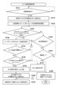
まず、ヒータHTの温度制御処理における永久故障判定に関して、図7に示すフローチャートを用いて説明する。図7は、MCU130が行うヒータHTの温度制御に係る動作に関するフローチャートである。図7に示す動作は、MCU130が有するROM(内蔵ROM)、もしくは不揮発性メモリ70に記憶されたプログラムを、MCU130が有するRAMに読み込んで実行することによって実施することができる。First, the permanent failure determination in the temperature control process of the heater HT will be explained using the flowchart shown in Figure 7. Figure 7 is a flowchart related to the operation related to the temperature control of the heater HT performed by the
S710でMCU130は、加熱開始指示が検出されたか否かを判定する。MCU130は、加熱開始指示が検出されたと判定されればS715を実行し、加熱開始指示が検出されたと判定されなければS710を再度実行する。In S710,
S715でMCU130は、不揮発性の記憶手段(MCU130が有するROMもしくは不揮発性メモリ70)に加熱中フラグを書き込む。フラグの書き込みは、フラグとして割り当てられた変数などの値を偽(例えば0)から真(例えば1)に変更することであってよい。At S715, the
S720でMCU130は、予め定められた温度制御パターンに従ったヒータHTの温度制御を開始する。上述したようにMCU130は、ヒータHTの温度取得と、取得した温度と温度制御パターンとに基づくヒータHTの電力供給制御とを繰り返し実行する。At S720, the
S725においてMCU130は、PB14端子に入力されているHEATER_Latched信号がローレベルからハイレベルに変化したか否かを判定する。HEATER_Latched信号がローレベルからハイレベルに変化したことは、FF2が保持する情報が、異常が検出されていないことを示す状態から異常が検出されたことを示す状態に変化したことに相当する。At S725, MCU130 determines whether the HEATER_Latched signal input to terminal PB14 has changed from low to high. The change of the HEATER_Latched signal from low to high corresponds to a change in the information held by FF2 from a state indicating that no abnormality has been detected to a state indicating that an abnormality has been detected.
MCU130は、HEATER_Latched信号がローレベルからハイレベルに変化したと判定されればS730を実行し、HEATER_Latched信号がローレベルからハイレベルに変化したと判定されなければS750を実行する。If the
S750でMCU130は、他の異常を検出したか否かを判定する。他の異常の検出には、ヒータHTの抵抗値に基づくヒータ温度の異常の検出、バッテリBTに関する異常条件に基づく異常の検出、およびローレベルのnALARM_Latched信号の入力に基づく異常の検出が含まれる。MCU130は、他の異常を検出したと判定されればS770を実行し、他の異常を検出したと判定されなければS755を実行する。In S750,
S755でMCU130は、制御を終了するか否かを判定する。MCU130は、温度制御パターンに規定された最後の区間が終了した場合、あるいはスライダ13が閉位置に移動されたことが検出された場合に、制御を終了すると判定することができる。MCU130は、制御を終了すると判定されればS760を実行し、制御を終了すると判定されなければS725を実行する。In S755,
S760でMCU130は、S715で書き込んだ制御中フラグを消去して、ヒータHTの温度制御動作を終了する。フラグの消去は、フラグとして割り当てられた変数などの値を真(例えば1)から偽(例えば0)に変更することであってよい。In S760, the
MCU130は、S720で温度制御パターンに従ったヒータHTの温度制御を開始してから、S755で温度制御を終了すると判定されるまでの間、S725、S750、およびS755の処理や、バッテリ監視回路100とのI2C通信などを、ヒータHTの温度取得およびヒータHTの電力供給制御と並行して実行する。From the time when
S725でHEATER_Latched信号がローレベルからハイレベルに変化したと判定された場合、S730でMCU130は、ヒータサーミスタTHを用いてヒータHTの温度を取得する。ここで、ヒータ温度をヒータサーミスタTHを用いて取得するのは、ヒータHTの温度制御においてヒータHTの抵抗値に基づいて取得したヒータ温度に異常が検出されていないためである。また、HEATER_Latched信号がハイレベルになったことで、nALARM_Latched信号がローレベルに変化してヒータHTへの電力供給が禁止されているためでもある。If it is determined in S725 that the HEATER_Latched signal has changed from low to high, in S730 the
S735でMCU130は、S735で取得したヒータ温度が予め定められた閾値以上か否か判定する。ここで用いる閾値は、必ずしも過加熱に相当する温度(例えば300℃)である必要はなく、ある程度の高温であることが確認できるものであってもよい。例えば220~250℃程度を閾値として用いることができる。MCU130は、ヒータ温度が予め定められた閾値以上と判定されればS740を実行し、ヒータ温度が予め定められた閾値以上と判定されなければS775を実行する。In S735,
S740でMCU130は、nALERM_Latched信号が異常を示すレベル(ここではローレベル)か否かを判定する。上述の通り、HEATER_Latched信号がハイレベルになったことで、nALARM_Latched信号がローレベルになっているはずである。しかし、HEATER_Latched信号がノイズなどによってハイレベルになっている可能性もある。特に、S735で用いる閾値が過加熱に相当する温度よりも低い場合、誤って永久故障が発生したと判定するおそれがある。そのため、nALARM_Latched信号がローレベルになっていることが確認できた場合のみ永久故障が発生したと判定するようにしている。In S740,
MCU130は、nALARM_Latched信号がローレベルであると判定されればS745を実行し、nALARM_Latched信号がローレベルであると判定されなければS775を実行する。
S775でMCU130は、発光部NUやバイブレータMを用いて、ユーザにリセット操作を行うように促す。
If it is determined that the nALARM_Latched signal is at a low level, the
In S775, the
S745でMCU130は、永久故障が発生したと判定する。
S765でMCU130は、MCU130が有するROMもしくは不揮発性メモリ70に永久故障フラグを書き込む。
In S745, the
In S765, the
S770でMCU130は、検出した異常に応じた処理を実行する。なお、ヒータHTの加熱が停止していなければ、MCU130は、検出した異常に応じた処理を実行する前に、Heater_Enable信号をローレベルしてヒータHTへの電力供給を禁止する。At S770, the
検出した異常に応じた処理のうち、永久故障以外の異常が検出された際の動作は既に説明したため、ここでは永久故障が発生したと判定された場合の処理について説明する。MCU130は、充電回路20とのI2C通信を通じて、充電回路20のパワーパス機能(BAT端子に入力される電力をSYS端子から出力する機能)を停止させる。これにより、充電回路20から電源電圧VBATに基づく電圧VCCの供給が停止され、さらに電圧VCCから派生する電圧VCC33_0、VCC33、VCC33_SLPの供給が停止される。したがって、MCU130を始めとしてほとんどの回路に電力が供給されず、電源ユニット1は実質的に動作を停止する。リブートコントローラ50への電力も供給されないため、リセット操作も受け付けなくなる。
Among the processes according to the detected abnormality, the operation when an abnormality other than a permanent failure is detected has already been described, so here, the process when it is determined that a permanent failure has occurred will be described. The
また、充電回路20のパワーパス機能を停止させることで、変圧回路120からヒータHTへの電力供給および充電回路20によるバッテリBTの充電も実行できなくなる。なお、重要な異常状態に該当すると判定された場合における電源ユニット1の安全性を向上させるため、永久故障が発生したと判定した場合、MCU130は、ユーザによる電源ユニット1の使用を禁止するための動作の一部として、充電回路20のパワーパス機能を停止させる前に、上述したHeater_Enable信号およびnCharger Enable信号を用いる方法によって変圧回路120からヒータHTへの電力供給および充電回路20によるバッテリBTの充電を禁止してもよい。In addition, by stopping the power path function of the charging
あるいは、MCU130は、S765を実行せずに、S770で発光部NUやバイブレータMによりユーザにリセット操作を行うように促してもよい。これは、MCU130自身の誤動作のおそれがあるため、リセット後の(再)起動処理において、永久故障の発生について再度判定するためである。永久故障が発生したと判定された場合、電源ユニット1が実質的に使用できなくなるため、判定は慎重に行う必要がある。
Alternatively,
以上が、ヒータHTの温度制御中における永久故障の判定に関する動作である。なお、MCU130は、ヒータHTの温度制御処理を行っていない状態でHEATER_Latched信号が異常を示すレベルに変化したことを検出した場合も、上述したS730以降の処理を実施することができる。The above is the operation related to determining whether or not there is a permanent failure during the temperature control of the heater HT. Note that the
((再)起動時における永久故障判定)
次に、(再)起動時における永久故障の判定動作について、図8に示すフローチャートを用いて説明する。図8は、MCU130が行う起動時の動作に関するフローチャートである。図8に示す動作は、MCU130が有するROM(内蔵ROM)、もしくは不揮発性メモリ70に記憶されたプログラムを、MCU130が有するRAMに読み込んで実行することによって実施することができる。
(Determining permanent failures during (re)startup)
Next, the operation of determining whether or not there is a permanent failure at (re)startup will be described with reference to the flowchart shown in Fig. 8. Fig. 8 is a flowchart relating to the operation at startup performed by the
S805でMCU130は、不揮発性の記憶手段(内蔵ROMもしくは不揮発性メモリ70)に永久故障フラグが存在するか否かを判定する。ここで、フラグが存在するとは、フラグが真値(1)であることに相当する。MCU130は、永久故障フラグが存在すると判定されればS830を実行し、永久故障フラグが存在すると判定されなければS810を実行する。In S805,
S810でMCU130は、内蔵ROMもしくは不揮発性メモリ70に制御中フラグが存在するか否かを判定する。MCU130は、制御中フラグが存在すると判定されればS815を実行し、制御中フラグが存在すると判定されなければS840を実行する。In S810, the
S815でMCU130は、HEATER_Latched信号が異常が検出されたことを示すレベル(ここではハイレベル)か否かを判定する。MCU130は、HEATER_Latched信号がハイレベルであると判定されればS820を実行し、HEATER_Latched信号がハイレベルであると判定されなければS835を実行する。In S815, the
上述の通り、FF2が保持する情報は、リセット動作によって消去されないため、リセット動作の実行前にヒータサーミスタTHによってヒータHTの過加熱が検出されていた場合には、再起動後もHEATER_Latched信号がハイレベルを維持している。As mentioned above, the information held by FF2 is not erased by the reset operation, so if overheating of the heater HT is detected by the heater thermistor TH before the reset operation is performed, the HEATER_Latched signal remains at a high level even after restart.
また、リセット後、電圧VCC33の供給が再開することにより、オペアンプA2およびMCU130が動作する。この時点でヒータHTの過熱状態が解消されていれば、オペアンプA2の出力はハイレベルに戻る。しかし、FF2の不図示のクロック端子へMCU130からクロック信号が入力されないため、FF2の保持する情報はリセット前から変化しない。そのため、リセット後にMCU130がHEATER_Latched信号を参照することにより、リセット前にヒータHTの過加熱が検出されていたことが確認できる。
After the reset, the supply of voltage V CC 33 is resumed, causing the operational amplifier A2 and the
S820でMCU130は、永久故障が発生したと判定する。
S825でMCU130は、MCU130が有するROMもしくは不揮発性メモリ70に永久故障フラグを書き込む。
In S820, the
In S825, the
S830でMCU130は、発光ユニットNUやバイブレータMを用いて、ユーザに永久故障が発生したことを報知する。また、MCU130は、電源ユニット1の起動を不能とする。具体的には、電源ユニット1をスリープ状態に維持し、スライダ13が開位置に移動されたことが検出されてもアクティブ状態には移行しないようにする。したがって、加熱開始指示が入力されても加熱は開始されない。あるいは、MCU130は、充電回路20とのI2C通信を通じて、充電回路20のパワーパス機能(BAT端子に入力される電力をSYS端子から出力する機能)を停止させてもよい。
In S830, the
例えば、S725における判定が、FF2の保持する情報がローレベルに変化したことではなく、ノイズによってPB14端子のレベルがローレベルになったことに起因している場合、リセット後にMCU130が参照するHEATER_Latched信号はローレベルであるため、永久故障判定時の動作が誤って実行されることが抑制される。また、MCU130がリセット前に誤動作していた場合も、リセットを行うことで、正常に動作した状態で永久故障の判定をより正確に実行することができる。For example, if the determination in S725 is due to the level of terminal PB14 going low due to noise, rather than the information held by FF2 having changed to a low level, the HEATER_Latched signal referenced by
S835でMCU130は、MCU130が有するROMもしくは不揮発性メモリ70から制御中フラグを消去する。そして、MCU130は正常に起動する。At S835,
S840でMCU130は、HEATER_Latched信号が異常が検出されたことを示すレベル(ここではハイレベル)か否かを判定する。MCU130は、HEATER_Latched信号がハイレベルであると判定されればS845を実行し、HEATER_Latched信号がハイレベルであると判定されなければS850を実行する。In S840, the
S845でMCU130は、発光部NUやバイブレータMを用いて、ユーザにリセット操作を行うように促す。これは、回路の誤動作が疑われるためである。
S850でMCU130は正常に起動する。
以上が、(再)起動時のおける永久故障の判定に関する動作である。
In S845, the
In S850, the
The above is the operation for determining whether or not there is a permanent failure when (re)starting up.
なお、永久故障であると判定された場合の処理は、(再)起動時に判定された場合と、起動後に判定された場合とで同じにしてもよいし、異ならせてもよい。ただし、いずれの場合であっても、少なくともヒータTHへの電力供給(ヒータ電圧VBOOSTの印加)は禁止する。これにより、電源ユニット1としての機能を果たすことができないため、電源ユニット1の使用を実質的に禁止することができる。また、ユーザがリセット操作を行った際に確実に永久故障の判定がなされるように、永久故障フラグの書き込みも実施することが好ましい。
The process when it is determined that the failure is permanent may be the same or different when it is determined at (re)startup and when it is determined after startup. However, in either case, at least the supply of power to the heater TH (application of the heater voltage V BOOST ) is prohibited. This prevents the
本実施形態によれば、エアロゾル生成装置の電源ユニットにおいて、装置の使用を実質的に禁止すべきヒータに関する異常(永久故障)を、ヒータの温度制御を行うMCU130とは異なる回路によってヒータに関する異常が検出されたことに応じて判定するようにした。そのため、何らかの原因によってMCU130でヒータに関する異常が検出できなかった場合であっても、装置の使用を実質的に禁止すべきヒータに関する異常を適切に判定することができる。According to this embodiment, in the power supply unit of the aerosol generating device, a heater abnormality (permanent failure) that should essentially prohibit the use of the device is determined in response to a heater abnormality being detected by a circuit different from the
また、MCU130とは異なる回路によってヒータに関する異常が検出されたことを示す情報を、電源ユニットのリセットによって消去されないように保持するようにした。そのため、リセット後にこの情報を参照することにより、MCU130が正常に動作している状態で改めて永久故障の判定を行うことができる。そのため、永久故障をより正確に判定することができる。
In addition, information indicating that a heater abnormality has been detected by a circuit other than
さらに、永久故障の判定を行った場合には、それを示す情報を不揮発性の記憶手段に記憶し、起動時に参照するようにした。そのため、一度永久故障の判定を行った後は確実に装置の使用を禁止することが可能になる。 Furthermore, if a permanent failure is determined, information indicating this is stored in a non-volatile storage means and is referenced at startup. This makes it possible to reliably prohibit the use of the device once a permanent failure has been determined.
発明は上記の実施形態に制限されるものではなく、発明の要旨の範囲内で、種々の変形・変更が可能である。 The invention is not limited to the above-described embodiments, and various modifications and variations are possible within the scope of the invention.
1…電源ユニット、10…ケース、11…フロントパネル、13…スライダ、130…MCU、SW…スイッチ、HT…ヒータ、TH…ヒータサーミスタ、TC…ケースサーミスタ、FF1,FF2…保持回路 1...power supply unit, 10...case, 11...front panel, 13...slider, 130...MCU, SW...switch, HT...heater, TH...heater thermistor, TC...case thermistor, FF1, FF2...holding circuit
Claims (4)
エアロゾル源を加熱する加熱部、
前記加熱部に接し、前記加熱部の温度を検知する第一の温度検知部、
前記加熱部に接しない、第二の温度検知部、
LED、及び
制御部を備える吸引装置であって、
前記制御部は、
前記電源から検出される電流値が閾値を超えた場合、前記電源の電流量が異常であると判定し、当該判定を前記LEDを用いて出力し、
前記電源から検出される電圧値が閾値を下回った場合、前記電源の電圧量が異常であると判定し、当該判定を前記LEDを用いて出力し、
前記第二の温度検知部から検出された温度が閾値を超えた場合、吸引装置本体の温度が異常であると判定し、当該判定を前記LEDを用いて出力し、
前記制御部が異常を判定し、当該判定を示すための前記LEDの出力は、異常に対する対応を前記吸引装置のユーザが分かる態様であること
を特徴とする吸引装置。 power supply,
A heating section for heating the aerosol source;
a first temperature detection unit that is in contact with the heating unit and detects the temperature of the heating unit;
A second temperature detection unit that is not in contact with the heating unit;
A suction device comprising an LED and a control unit,
The control unit is
When a current value detected from the power supply exceeds a threshold value, it is determined that the current amount of the power supply is abnormal, and the determination is outputted using the LED;
When a voltage value detected from the power supply falls below a threshold value, it is determined that the voltage amount of the power supply is abnormal, and the determination is outputted using the LED;
When the temperature detected by the second temperature detection unit exceeds a threshold value, it is determined that the temperature of the suction device body is abnormal, and the determination is output using the LED;
The control unit determines an abnormality, and the output of the LED for indicating the determination is in a manner that enables a user of the suction device to know how to respond to the abnormality.
エアロゾル源を加熱する加熱部、
前記加熱部に接し、前記加熱部の温度を検知する第一の温度検知部、
前記加熱部に接しない、第二の温度検知部、
LED、及び
制御部を備える吸引装置であって、
前記制御部は、
前記電源から検出される電流値が閾値を超えた場合、前記電源の電流量が異常であると判定し、当該判定を前記LEDを用いて出力し、
前記電源から検出される電圧値が閾値を下回った場合、前記電源の電圧量が異常であると判定し、当該判定を前記LEDを用いて出力し、
前記電源の温度が閾値を超えた場合、前記電源の温度が異常であると判定し、当該判定を前記LEDを用いて出力し、
前記第二の温度検知部から検出された温度が閾値を超えた場合、吸引装置本体の温度が異常であると判定し、当該判定を前記LEDを用いて出力する
ことを特徴とする吸引装置。 power supply,
A heating section for heating the aerosol source;
a first temperature detection unit that is in contact with the heating unit and detects the temperature of the heating unit;
A second temperature detection unit that is not in contact with the heating unit;
A suction device comprising an LED and a control unit,
The control unit is
When a current value detected from the power supply exceeds a threshold value, it is determined that the current amount of the power supply is abnormal, and the determination is outputted using the LED;
When a voltage value detected from the power supply falls below a threshold value, it is determined that the voltage amount of the power supply is abnormal, and the determination is outputted using the LED;
If the temperature of the power supply exceeds a threshold value, the temperature of the power supply is determined to be abnormal, and the determination is output using the LED;
When the temperature detected by the second temperature detection unit exceeds a threshold value, the temperature of the suction device body is determined to be abnormal, and the determination is output using the LED.
ことを特徴とする請求項2記載の吸引装置。 The suction device according to claim 2 , wherein the control unit acquires information about a temperature of the power source from the power source.
ことを特徴とする請求項3記載の吸引装置。 4. The suction device according to claim 3, wherein the control unit determines an abnormality, and the output of the LED for indicating the determination is in a manner that allows a user of the suction device to know how to deal with the abnormality.
Priority Applications (1)
| Application Number | Priority Date | Filing Date | Title |
|---|---|---|---|
| JP2024216882A JP7829667B2 (en) | 2021-05-10 | 2024-12-11 | suction device |
Applications Claiming Priority (1)
| Application Number | Priority Date | Filing Date | Title |
|---|---|---|---|
| PCT/JP2021/017702 WO2022239065A1 (en) | 2021-05-10 | 2021-05-10 | Power supply unit for aerosol generation device, and method therefor |
Related Child Applications (1)
| Application Number | Title | Priority Date | Filing Date |
|---|---|---|---|
| JP2024216882A Division JP7829667B2 (en) | 2021-05-10 | 2024-12-11 | suction device |
Publications (3)
| Publication Number | Publication Date |
|---|---|
| JPWO2022239065A1 JPWO2022239065A1 (en) | 2022-11-17 |
| JPWO2022239065A5 JPWO2022239065A5 (en) | 2023-12-27 |
| JP7604635B2 true JP7604635B2 (en) | 2024-12-23 |
Family
ID=84028496
Family Applications (2)
| Application Number | Title | Priority Date | Filing Date |
|---|---|---|---|
| JP2023520585A Active JP7604635B2 (en) | 2021-05-10 | 2021-05-10 | Power supply unit and method for aerosol generating device |
| JP2024216882A Active JP7829667B2 (en) | 2021-05-10 | 2024-12-11 | suction device |
Family Applications After (1)
| Application Number | Title | Priority Date | Filing Date |
|---|---|---|---|
| JP2024216882A Active JP7829667B2 (en) | 2021-05-10 | 2024-12-11 | suction device |
Country Status (6)
| Country | Link |
|---|---|
| US (1) | US20240023630A1 (en) |
| EP (1) | EP4338624A4 (en) |
| JP (2) | JP7604635B2 (en) |
| KR (1) | KR20240004699A (en) |
| CN (1) | CN117255633A (en) |
| WO (1) | WO2022239065A1 (en) |
Families Citing this family (2)
| Publication number | Priority date | Publication date | Assignee | Title |
|---|---|---|---|---|
| US12520880B2 (en) | 2021-01-18 | 2026-01-13 | Altria Client Services Llc | Heat-not-burn (HNB) aerosol-generating devices including energy based heater control, and methods of controlling a heater |
| WO2026041505A1 (en) * | 2024-08-20 | 2026-02-26 | Jt International Sa | A reset circuit of an aerosol generating device |
Citations (5)
| Publication number | Priority date | Publication date | Assignee | Title |
|---|---|---|---|---|
| JP2019524113A (en) | 2016-07-25 | 2019-09-05 | フィリップ・モーリス・プロダクツ・ソシエテ・アノニム | Heater management |
| JP6728509B1 (en) | 2020-03-05 | 2020-07-22 | 日本たばこ産業株式会社 | Power supply unit for aerosol inhalers |
| US20200237007A1 (en) | 2019-01-29 | 2020-07-30 | Changzhou Patent Electronic Technology Co., Ltd. | Voltage output circuit, electronic device and electronic cigarette |
| JP2020171208A (en) | 2019-04-09 | 2020-10-22 | 日本たばこ産業株式会社 | A method of operating the power supply unit, the suction device, and the power supply unit provided in the suction device. |
| WO2020255233A1 (en) | 2019-06-18 | 2020-12-24 | 日本たばこ産業株式会社 | Inhalation device, power supply unit, and method |
Family Cites Families (2)
| Publication number | Priority date | Publication date | Assignee | Title |
|---|---|---|---|---|
| GB201701102D0 (en) | 2017-01-23 | 2017-03-08 | Nicoventures Holdings Ltd | Electronic vapour provision system |
| EA039503B1 (en) * | 2017-10-18 | 2022-02-03 | Джапан Тобакко Инк. | DEVICE GENERATING INHALATION COMPONENT, METHOD OF CONTROL OF DEVICE GENERATING INHALATION COMPONENT AND PROGRAM |
-
2021
- 2021-05-10 JP JP2023520585A patent/JP7604635B2/en active Active
- 2021-05-10 CN CN202180097736.3A patent/CN117255633A/en active Pending
- 2021-05-10 WO PCT/JP2021/017702 patent/WO2022239065A1/en not_active Ceased
- 2021-05-10 KR KR1020237041002A patent/KR20240004699A/en active Pending
- 2021-05-10 EP EP21941799.5A patent/EP4338624A4/en active Pending
-
2023
- 2023-10-05 US US18/481,662 patent/US20240023630A1/en active Pending
-
2024
- 2024-12-11 JP JP2024216882A patent/JP7829667B2/en active Active
Patent Citations (5)
| Publication number | Priority date | Publication date | Assignee | Title |
|---|---|---|---|---|
| JP2019524113A (en) | 2016-07-25 | 2019-09-05 | フィリップ・モーリス・プロダクツ・ソシエテ・アノニム | Heater management |
| US20200237007A1 (en) | 2019-01-29 | 2020-07-30 | Changzhou Patent Electronic Technology Co., Ltd. | Voltage output circuit, electronic device and electronic cigarette |
| JP2020171208A (en) | 2019-04-09 | 2020-10-22 | 日本たばこ産業株式会社 | A method of operating the power supply unit, the suction device, and the power supply unit provided in the suction device. |
| WO2020255233A1 (en) | 2019-06-18 | 2020-12-24 | 日本たばこ産業株式会社 | Inhalation device, power supply unit, and method |
| JP6728509B1 (en) | 2020-03-05 | 2020-07-22 | 日本たばこ産業株式会社 | Power supply unit for aerosol inhalers |
Also Published As
| Publication number | Publication date |
|---|---|
| KR20240004699A (en) | 2024-01-11 |
| EP4338624A4 (en) | 2025-08-13 |
| JPWO2022239065A1 (en) | 2022-11-17 |
| US20240023630A1 (en) | 2024-01-25 |
| JP2025026685A (en) | 2025-02-21 |
| EP4338624A1 (en) | 2024-03-20 |
| JP7829667B2 (en) | 2026-03-13 |
| WO2022239065A1 (en) | 2022-11-17 |
| CN117255633A (en) | 2023-12-19 |
Similar Documents
| Publication | Publication Date | Title |
|---|---|---|
| JP7829667B2 (en) | suction device | |
| JP7554354B2 (en) | Aerosol generator power supply unit | |
| JP7708989B2 (en) | Aerosol generator power supply unit | |
| JP7624511B2 (en) | Aerosol generator power supply unit | |
| JP7749073B2 (en) | Aerosol generator power supply unit | |
| JP7748512B2 (en) | Aerosol generator power supply unit | |
| US20240057690A1 (en) | Power supply unit of aerosol generation device | |
| US20240065336A1 (en) | Power supply unit of aerosol generation device | |
| US20240074495A1 (en) | Power supply unit for aerosol generating device | |
| JP7692056B2 (en) | Aerosol generator power supply unit | |
| JP7692055B2 (en) | Aerosol generator power supply unit | |
| WO2022239279A1 (en) | Power supply unit for aerosol generation device | |
| WO2022239280A1 (en) | Power supply unit for aerosol generation device | |
| WO2022239514A1 (en) | Power supply unit of aerosol generation device | |
| CN118369008A (en) | Power supply unit for aerosol generating device | |
| WO2022239473A1 (en) | Power supply unit for aerosol generation device | |
| WO2022239474A1 (en) | Power supply unit for aerosol generation device | |
| JP7104868B1 (en) | Aerosol generator | |
| JP7104262B1 (en) | Power supply unit for aerosol generator | |
| WO2022239510A1 (en) | Power supply unit for aerosol generation device | |
| WO2022239472A1 (en) | Power supply unit for aerosol generation device | |
| JP7505127B2 (en) | Aerosol generator power supply unit | |
| WO2022239509A1 (en) | Power supply unit for aerosol generation device | |
| EA050958B1 (en) | AEROSOL GENERATING DEVICE | |
| EA052266B1 (en) | POWER SUPPLY FOR AEROSOL GENERATING DEVICE |
Legal Events
| Date | Code | Title | Description |
|---|---|---|---|
| A521 | Request for written amendment filed |
Free format text: JAPANESE INTERMEDIATE CODE: A523 Effective date: 20230926 |
|
| A621 | Written request for application examination |
Free format text: JAPANESE INTERMEDIATE CODE: A621 Effective date: 20230926 |
|
| A131 | Notification of reasons for refusal |
Free format text: JAPANESE INTERMEDIATE CODE: A131 Effective date: 20240830 |
|
| A521 | Request for written amendment filed |
Free format text: JAPANESE INTERMEDIATE CODE: A523 Effective date: 20241028 |
|
| TRDD | Decision of grant or rejection written | ||
| A01 | Written decision to grant a patent or to grant a registration (utility model) |
Free format text: JAPANESE INTERMEDIATE CODE: A01 Effective date: 20241111 |
|
| A61 | First payment of annual fees (during grant procedure) |
Free format text: JAPANESE INTERMEDIATE CODE: A61 Effective date: 20241211 |
|
| R150 | Certificate of patent or registration of utility model |
Ref document number: 7604635 Country of ref document: JP Free format text: JAPANESE INTERMEDIATE CODE: R150 |