WO2020255233A1 - Inhalation device, power supply unit, and method - Google Patents
Inhalation device, power supply unit, and method Download PDFInfo
- Publication number
- WO2020255233A1 WO2020255233A1 PCT/JP2019/023995 JP2019023995W WO2020255233A1 WO 2020255233 A1 WO2020255233 A1 WO 2020255233A1 JP 2019023995 W JP2019023995 W JP 2019023995W WO 2020255233 A1 WO2020255233 A1 WO 2020255233A1
- Authority
- WO
- WIPO (PCT)
- Prior art keywords
- power supply
- supply unit
- unit
- normal
- suction device
- Prior art date
Links
Images


Classifications
-
- A—HUMAN NECESSITIES
- A24—TOBACCO; CIGARS; CIGARETTES; SIMULATED SMOKING DEVICES; SMOKERS' REQUISITES
- A24F—SMOKERS' REQUISITES; MATCH BOXES; SIMULATED SMOKING DEVICES
- A24F40/00—Electrically operated smoking devices; Component parts thereof; Manufacture thereof; Maintenance or testing thereof; Charging means specially adapted therefor
- A24F40/50—Control or monitoring
- A24F40/51—Arrangement of sensors
-
- A—HUMAN NECESSITIES
- A24—TOBACCO; CIGARS; CIGARETTES; SIMULATED SMOKING DEVICES; SMOKERS' REQUISITES
- A24F—SMOKERS' REQUISITES; MATCH BOXES; SIMULATED SMOKING DEVICES
- A24F40/00—Electrically operated smoking devices; Component parts thereof; Manufacture thereof; Maintenance or testing thereof; Charging means specially adapted therefor
- A24F40/50—Control or monitoring
- A24F40/53—Monitoring, e.g. fault detection
-
- A—HUMAN NECESSITIES
- A24—TOBACCO; CIGARS; CIGARETTES; SIMULATED SMOKING DEVICES; SMOKERS' REQUISITES
- A24F—SMOKERS' REQUISITES; MATCH BOXES; SIMULATED SMOKING DEVICES
- A24F40/00—Electrically operated smoking devices; Component parts thereof; Manufacture thereof; Maintenance or testing thereof; Charging means specially adapted therefor
- A24F40/60—Devices with integrated user interfaces
Definitions
- This disclosure relates to a suction device, a power supply unit, and a method.
- the present invention relates to a suction device for generating an aerosol, a power supply unit used for the suction device, and a method for operating a suction device for generating an aerosol.
- a suction device such as an electronic cigarette that produces a suction component such as a flavored aerosol
- Lithium-ion batteries are often used as batteries for such electronic devices. Then, the lithium ion battery may have a problem due to deterioration over time, for example. Therefore, when a problem related to the battery occurs, there is an electronic device that detects the fact.
- Patent Document 1 when the user is using the suction device (when the battery is discharged), when the power supply voltage falls below the threshold voltage, it is determined that an error has occurred in the battery and the number of times is counted. It is disclosed to do.
- the number of times exceeds a predetermined threshold value, the fact that the battery needs to be replaced is transmitted through the activation of the replacement indicator.
- the electronic device If a problem occurs when the battery is discharged, it is desirable that the electronic device not only detect the power supply abnormality but also acquire more detailed information. Specifically, it is necessary to identify factors such as whether it is due to a sudden battery failure or due to aging such as battery life, and to present diagnostic information including such information to the user in an easy-to-understand manner. Is desirable. In particular, in the suction device, since the aerosol source is heated according to the power supply from the power supply, not only the detection of the power supply abnormality but also more detailed information should be obtained from the viewpoint of safety. ..
- one of the purposes of the present disclosure is to appropriately grasp the state of the power supply unit including the battery and notify the user of the use of the suction device.
- one of the purposes is for the suction device to determine the state of power failure when a problem occurs when the battery is discharged.
- Another object of the present invention is to appropriately control the operation of the suction device according to the determined power supply abnormality.
- one of the purposes is to output diagnostic information for identifying the degree and cause of the power supply abnormality and to urge the user to deal with the power supply abnormality.
- a suction device that produces an aerosol.
- a suction device includes a heating unit that atomizes the aerosol source, a power supply unit that performs a power supply operation to the heating unit, a sensor that detects the voltage value of the power supply unit, and a total number of power supply counts according to the power supply operation.
- a control unit that determines the state of the power supply unit based on the number of normal power supplies, and the number of normal power supplies is counted when the voltage value of the power supply unit is equal to or higher than a predetermined voltage threshold value through the power supply operation.
- a notification unit for notifying the status of the power supply unit.
- the suction device By using two parameters, the total number of times of power supply and the number of times of normal power supply, the suction device appropriately determines the normal or abnormal state of the power supply unit when the suction device is used, especially when the battery is discharged during the suction operation by the user. It can be grasped and notified to the user.
- the notification unit notifies the state of the power supply unit in a different manner based on the total number of times of power supply.
- the user using the suction device can intuitively grasp the normal or abnormal state of the power supply unit when the battery is discharged by perceiving the notification mode.
- the convenience of repairing the suction device can be improved.
- the suction device of the third viewpoint is the state of the power supply unit in the suction device of the first viewpoint or the second viewpoint when the control unit does not count the normal power supply count and the total power supply count and the normal power supply count do not match. Determines that the power supply is abnormal.
- the control unit of the suction device reliably determines the abnormal state of the power supply unit during battery discharge when a problem occurs during battery discharge. be able to.
- the control unit does not count the number of normal feeds over a plurality of times, and the difference between the total number of feeds and the number of normal feeds is predetermined. When the threshold number of times is reached, it is determined that the state of the power supply unit is abnormal. As a result, the control unit of the suction device can more accurately determine the abnormal state of the power supply unit when the battery is discharged.
- the total number of times of feeding and the number of normal feedings are associated with each other in any of the suction devices of the first to the fourth viewpoints, and the control unit continuously performs a plurality of times of normal feeding.
- the difference between the total number of times of power supply and the number of times of normal power supply reaches a predetermined threshold number without being counted over, it is determined that the state of the power supply unit is abnormal.
- the control unit of the suction device can more accurately determine the abnormal state of the power supply unit when the battery is discharged.
- the control unit stores the power supply abnormality information in the memory when the state of the power supply unit is determined to be a power supply abnormality. , Prohibits power supply operation by the power supply unit according to the storage of power supply abnormality information.
- the control unit of the suction device can enhance the safety to the user by prohibiting the power supply operation by the power supply unit.
- the control unit further deletes the power supply abnormality information stored in the memory, and in response to the deletion of the power supply abnormality information, the prohibited power supply operation is performed. To give permission.
- the control unit of the suction device can improve the convenience of the user by re-permitting the once prohibited power feeding operation.
- the suction device of the eighth viewpoint is the suction device of the seventh viewpoint, and the control unit deletes the power supply abnormality information in response to an instruction from an external device connected to the suction device. As a result, it is possible to prevent the malfunction of the suction operation due to the erroneous operation of the user and enhance the safety for the user.
- the power supply operation by the power supply unit is started in response to the pressing of the power switch of the user, and is carried out for a predetermined time.
- a power supply unit used for a suction device that produces an aerosol includes a heating unit that atomizes the aerosol source, a power supply unit that performs a power supply operation to the heating unit, a sensor that detects the voltage value of the power supply unit, and a total number of power supply counts according to the power supply operation.
- a control unit that determines the state of the power supply unit based on the number of normal power supplies, and the number of normal power supplies is counted when the voltage value of the power supply unit is equal to or higher than a predetermined voltage threshold through the power supply operation.
- a notification unit for notifying the status of the power supply unit.
- the power supply unit can appropriately determine the normal or abnormal state of the power supply unit when the power supply unit is used, especially when the battery is discharged during suction operation by the user. It can be grasped and notified to the user.
- the notification unit notifies the state of the power supply unit in a different manner based on the total number of times of power supply.
- the user during the suction operation can intuitively grasp the normal or abnormal state of the power supply unit when the battery is discharged by perceiving the notification mode.
- the convenience of repairing the power supply unit can be improved.
- the power supply unit of the twelfth viewpoint is the state of the power supply unit in the tenth viewpoint or the eleventh viewpoint, when the control unit does not count the normal power supply count and the total power supply count and the normal power supply count do not match. Determines that the power supply is abnormal.
- the control unit of the power supply unit uses two parameters, the total number of power supplies and the number of normal power supplies, to reliably determine the abnormal state of the power supply unit during battery discharge when a problem occurs during battery discharge. be able to.
- the control unit does not count the number of normal power supplies over a plurality of times, and the difference between the total number of power supplies and the number of normal power supplies is predetermined. When the threshold number of times is reached, it is determined that the state of the power supply unit is abnormal. As a result, the control unit of the power supply unit can more accurately determine the abnormal state of the power supply unit when the battery is discharged.
- the total number of times of power supply and the number of times of normal power supply are associated with each other of the power supply unit of the 10th to 13th viewpoints, and the control unit has a plurality of times of normal power supply in succession.
- the difference between the total number of times of power supply and the number of times of normal power supply reaches a predetermined threshold number without being counted over, it is determined that the state of the power supply unit is abnormal.
- the control unit of the power supply unit can more accurately determine the abnormal state of the power supply unit when the battery is discharged.
- the power supply unit of the fifteenth viewpoint is any power supply unit from the tenth viewpoint to the fourteenth viewpoint, and the control unit stores the power supply abnormality information in the memory when it is determined that the state of the power supply unit is abnormal. It is stored, and the power supply operation by the power supply unit is prohibited according to the storage of power supply abnormality information.
- the control unit of the power supply unit can enhance safety for the user by prohibiting the power supply operation by the power supply unit.
- the control unit further deletes the power supply abnormality information stored in the memory in response to an instruction from an external device connected to the power supply unit. Allows prohibited power supply operations according to the deletion of power supply error information.
- the control unit of the suction device can prevent the suction operation from malfunctioning due to the user's erroneous operation and enhance the safety to the user.
- the convenience of the user can be enhanced by re-permitting the once prohibited power feeding operation.
- the sensor in any of the power supply units of the 10th to 16th viewpoints, includes a suction sensor, and the power supply operation by the power supply unit is detected by the suction sensor, and a series of suction operations by the user. It is started according to the start of, and is carried out until the end of a series of suction operations.
- a method of operating a suction device that produces an aerosol is provided.
- a step of causing the power supply unit to perform a power supply operation to the heating unit for atomizing the aerosol source a step of causing the sensor to detect the voltage value of the power supply unit, a total number of power supply counts counted according to the power supply operation, and normality.
- a step of determining the state of the power supply unit based on the number of times of power supply, and the number of times of normal power supply is counted when the voltage value of the power supply unit is equal to or higher than a predetermined voltage threshold value through the power supply operation. Includes steps to notify the status of.
- the method By using two parameters, the total number of times of power supply and the number of times of normal power supply, the method appropriately grasps the normal or abnormal state of the power supply unit when the suction device is used, especially when the battery is discharged during the suction operation by the user. And can notify the user.
- the method of the 19th viewpoint includes, in the method of the 18th viewpoint, the step of notifying is notifying the state of the power supply unit in a different manner based on the total number of times of power supply.
- the user during the suction operation can intuitively grasp the normal or abnormal state of the power supply unit when the battery is discharged by perceiving the notification mode.
- the convenience of repairing the suction device can be improved.
- the method of the 20th viewpoint is the state of the power supply unit in the method of the 18th viewpoint or the 19th viewpoint when the determination step is that the normal power supply count is not counted and the total power supply count and the normal power supply count do not match. Includes determining that is a power failure. By using two parameters, the total number of times of power supply and the number of times of normal power supply, it is possible to reliably determine the abnormal state of the power supply unit at the time of battery discharge when a problem occurs during battery discharge.
- FIG. 1A is an overall perspective view of the suction device according to the first embodiment.
- FIG. 1B is an overall perspective view of the suction device according to the first embodiment.
- FIG. 2 is a schematic block diagram of the configuration of the suction device according to the first embodiment.
- FIG. 3 is a schematic flow chart of an operation method of the suction device according to the first embodiment.
- FIG. 4 is a detailed flow chart of the operation method of the suction device according to the first embodiment.
- FIG. 5 is a schematic flow chart of an operation method of the suction device according to the first embodiment.
- FIG. 6 is a schematic flow chart of an operation method of the suction device according to the first embodiment.
- FIG. 7 is a modified example of the detailed flow chart shown in FIG.
- FIG. 8 is a modified example of the detailed flow chart shown in FIG.
- FIG. 9 is a schematic block diagram of the configuration of the suction device according to the second embodiment.
- the suction device includes, but is not limited to, an electronic cigarette and a nebulizer.
- the suction device may include various suction devices for producing aerosols that the user sucks or flavored aerosols.
- the generated suction component source may also contain invisible vapors.
- FIG. 1A is an overall perspective view of the suction device 10 according to the first embodiment.
- FIG. 1B is an overall perspective view of the suction device 10 in a state of holding the aerosol-forming base material according to the first embodiment.
- the suction device 10 is detachably attached to, for example, an aerosol-generating base material such as a suction article 15 having a flavor-generating base material such as an aerosol source and a filler containing a flavor source.
- an aerosol-generating base material such as a suction article 15 having a flavor-generating base material such as an aerosol source and a filler containing a flavor source.
- the aerosol-producing base material is an example of the suction article 15 (hereinafter, the aerosol-producing base material may be collectively referred to as the suction article).
- the aerosol source contained in the aerosol-forming substrate may be a solid or a liquid.
- the aerosol source may be, for example, a polyhydric alcohol such as glycerin or propylene glycol, or a liquid such as water.
- the aerosol source may include a tobacco raw material that releases a flavor component by heating or an extract derived from the tobacco raw material. If the aspirator 10 is a medical inhaler such as a nebulizer, the aerosol source may include a drug for the patient to inhale.
- the aerosol-forming substrate may not contain a flavor source.
- the suction device 10 has a top housing 11A, a bottom housing 11B, a cover 12, a power button 13, and a lid 14.
- the top housing 11A and the bottom housing 11B are connected to each other to form the outermost housing 11 of the suction device 10.
- the housing 11 may be sized to fit in the user's hands. In this case, when the user uses the suction device 10, the user holds the suction device 10 by hand and sucks the aerosol.
- the top housing 11A has an opening (not shown), and the cover 12 is coupled to the top housing 11A so as to close the opening.
- the cover 12 has an opening 12a into which the suction article 15 can be inserted.
- the lid portion 14 is configured to open and close the opening 12a of the cover 12. Specifically, the lid portion 14 is attached to the cover 12 and is configured to be movable along the surface of the cover 12 between the first position for closing the opening 12a and the second position for opening the opening 12a. ..
- the power button 13 is used to switch the power of the suction device 10 on and off.
- the user presses the power button 13 with the suction article 15 inserted in the opening 12a to supply electric power from the power supply unit to the heating unit, which will be described later, for a certain period of time.
- an aerosol is generated from the aerosol source contained in the suction article 15, and the flavor of the flavor source is incorporated into the aerosol.
- the user can suck the aerosol containing the flavor by performing the suction operation from the portion of the suction article 15 (the portion shown in FIG. 1B) protruding from the suction device 10.
- the bottom housing 11B is formed with a vent (not shown) for allowing air to flow into the inside of the heating assembly described later. Specifically, the vent is in fluid communication with one end of the heating assembly.
- the configuration of the suction device 10 shown in FIGS. 1A and 1B is only an example of the configuration of the suction device according to the present disclosure.
- the suction device 10 according to the present disclosure is configured in various forms such that an aerosol can be generated by heating a suction article 15 including an aerosol source, and the user can suck the generated aerosol source. can do.
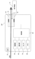
- FIG. 2 is a block diagram schematically showing the configuration of the suction device 10 according to the present embodiment.
- the suction device 10 includes a power supply unit 20, a heating unit 40, a control unit 50, a notification unit 60, a sensor 70, and a memory 80, and is electrically connected.
- the power supply unit 20 has a power supply that can be, for example, a rechargeable battery or a non-rechargeable battery.
- the power supply unit 20 supplies electric power to each component such as the heating unit 40, the control unit 50, the notification unit 60, the sensor 70, and the memory 80.
- a power supply operation for supplying electric power from the power supply unit 20 to the heating unit 40 is performed for a predetermined period, and the heating unit 40 is operated so as to heat the suction article 15. ..
- the suction device 10 may have an external connection terminal 22 (terminal) that can be connected to an external power source (not shown).
- the external connection terminal 22 can be connected to, for example, a cable such as a micro USB (Universal Serial Bus).
- a current can be passed from the external power source to the power source to charge the power source.
- data related to the operation of the suction device 10 may be transmitted / received to / from an external device (not shown).
- an external device not shown
- new data can be stored in the memory 80 of the suction device 10 by the external device, and the stored data can be updated and deleted. It may be configured in.
- the heating unit 40 has a heating assembly, is configured to accommodate a part of the suction article 15 inside, has a function of defining a flow path of air supplied to the suction article 15, and has an outer circumference or a center of the suction article 15. Has the function of heating from. As a result, the aerosol source is atomized to produce an aerosol containing a flavor.
- the suction device 10 includes a concave holding portion 45 capable of receiving the suction article 15 and holding the filling.
- the heating unit 40 may have a shape that heats the suction article 15 received by insertion from the outer circumference or the center. That is, the heating unit 40 can heat the portion of the suction article 15 including the flavor source held by the holding unit 45 through the power supply of electric power from the power supply unit 20.
- the control unit 50 is configured to control the operation of each component such as the power supply unit 20, the heating unit 40, the notification unit 60, the sensor 70, and the memory 80. Further, the control unit 50 is configured to exchange information with each component.
- the control unit 50 may be an electronic circuit module configured as a microprocessor or a microcomputer.
- the control unit 50 controls the operation of the suction device 10 according to a computer executable instruction stored in the memory 80.
- the control unit 50 reads data from the memory 80 as needed, uses the data for controlling the suction device 10, and stores the generated data in the memory 80 as needed.
- the control unit 50 is configured to determine the state of the power supply unit 20 based on the total number of times of power supply and the number of normal power supplies counted according to the power supply operation of the power supply unit 20 to the heating unit 40. ..
- the number of normal power feeds is configured to be counted when the voltage value of the power supply unit 20 is equal to or higher than a predetermined voltage threshold value through the power supply operation. That is, the control unit 50 uses two parameters, the total number of times of power supply and the number of times of normal power supply, so that the normal or abnormal state of the power supply unit when the suction device 10 is used, particularly when the battery is discharged during the suction operation by the user. Can be properly grasped.
- the notification unit 60 operates so as to give an explicit notification to the user. Specifically, the notification unit 60 notifies the user in various modes by light emission, display, vocalization, vibration, and a combination thereof, as necessary.
- the notification unit 60 may include one or more LEDs, and may be configured to emit light in one or more colors depending on the determined state of the power supply unit 20.
- the notification unit 60 is configured to notify the state of the power supply unit 20. For example, it may be configured to notify whether the power supply unit 20 is in a normal state or an abnormal state, and further notify the state of the power supply unit 20 in a different manner based on the total number of times of power supply.
- the user can intuitively grasp the normal or abnormal state of the power supply unit when the battery is discharged by perceiving the notification mode.
- the convenience of repairing the suction device 10 can be improved. Specifically, for example, when the user inquires about the abnormal state to the manufacturer, the manufacturer decides whether the LED can be repaired or cannot be repaired by simply telling the light emitting mode (for example, the light emitting color) of the LED, and the user. You will be able to get guidance immediately.
- the sensor 70 may include a pressure sensor that detects pressure fluctuations in the air intake flow path and / or aerosol flow path from the vent to the heating assembly or a flow rate sensor that detects the flow rate.
- the sensor 70 may also include a weight sensor that detects the weight of the component in the suction article 15.
- the sensor 70 may also be configured to detect the height of the internal liquid level when the aerosol source is a liquid.
- the sensor 70 may also detect and / or calculate the SOC (System of Charge, charging state) of the power supply unit 20, the discharge state of the power supply unit 20, the current integrated value, and the like.
- the sensor 70 may also be an operation button or the like that can be operated by the user.
- the sensor 70 is configured to detect the voltage value in the power supply unit 20 over the discharge state (that is, the power supply operation from the power supply unit 20 to the heating unit 40). Further, the sensor 70 is configured to detect the pressing of the power button 13. Further, the sensor 70 may be configured to include a suction sensor, such as a microphone capacitor, to detect a suction action by the user and, in particular, to identify the start and end of a series of suction actions by the user. Good.
- a suction sensor such as a microphone capacitor
- the senor 70 may be a temperature detection unit configured to detect the temperature of the heating unit 40 (or the load included in the heating unit 40).
- the temperature detection unit detects a value required to obtain the resistance value of the load of the heating unit 40 (current value flowing through the load of the heating unit 40, voltage value applied to the load of the heating unit 40, etc.). It may be configured.
- the temperature detection unit may include a temperature sensor that detects the temperature of the heating unit 40.
- the memory 80 is a storage medium such as a ROM (Read Only Memory), a RAM (Random Access Memory), and a flash memory.
- the memory 80 can store various data related to the operation of the suction device 10.
- the memory 80 may store data of a heating profile defined in advance for the heating unit 40.
- the memory 80 may store computer executable instructions, setting data necessary for controlling the suction device 10, and programs such as firmware.
- the memory 80 may store various data related to the control method of the notification unit 60 (modes such as light emission, vocalization, vibration, etc.), the value detected by the sensor 70, and the like.
- the memory 80 enables a program for causing the suction device 10 to execute the entire operation described later, and the control unit 50 executes the program.
- the memory 80 stores power supply usage history information including the total number of power supplies and the number of normal power supplies, which are counted by the control unit 50 and used to determine the state of the power supply unit 20. Further, when the power supply unit 20 is determined to be "power supply abnormality", the power supply abnormality information specified based on the total number of times of power supply is stored. Various information may be registered in the database in a table format.
- FIGS. 3 to 6 are schematic flow charts showing a method of operating the suction device 10 according to the present embodiment. The operation in each flow diagram is mainly performed by the control unit 50.
- 3 and 4 are schematic flow charts for determining the state of the power supply unit 20 and setting the state of the suction device 10 to "normal power supply” or "abnormal power supply”.
- FIG. 5 is a schematic flow diagram for prohibiting the power supply operation of the power supply unit when it is determined that the state of the power supply unit 20 is “power supply abnormality”
- FIG. 6 is a schematic flow diagram for temporarily prohibiting the power supply operation. After that, it is a schematic flow diagram for permitting the power feeding operation again.
- the initialization process includes setting the values of the total number of times of power supply and the number of times of normal power supply to "0". While the power supply unit 20 is in use, the values of the total number of times of power supply and the number of times of normal power supply are continuously counted. On the other hand, for example, when the power supply unit 20 is replaced by repair, the initialization process is performed again and the values of the total number of times of power supply and the number of times of normal power supply are reset to "0". In the present specification, "counting" the number of times includes setting the value of the number of times to a value incremented by +1.
- the total number of times of power supply is the total number of times the power supply unit 20 has performed the power supply operation to the heating unit 40. For example, the total number of times of power supply may be counted each time the power supply operation is started.
- the normal power supply count is the power supply operation when the voltage value of the power supply unit 20 periodically detected by the sensor 70 is maintained at or above a predetermined voltage threshold value from the start to the end of the power supply operation. Is the number of times that is counted as normal. On the other hand, if the voltage value of the power supply unit 20 becomes less than the predetermined voltage threshold value even once through the power supply operation, the value of the normal power supply count is not counted.
- the control unit 50 may determine that the state of the power supply unit 20 is "normal power supply”. On the other hand, if the total number of power supplies and the number of normal power supplies do not match without counting the number of normal power supplies, the control unit 50 may determine that the state of the power supply unit 20 is "power supply abnormality”. .. In this way, the suction device 10 can appropriately grasp the normal or abnormal state of the power supply unit at the time of battery discharge during the suction operation by the user by using two parameters of the total number of times of power supply and the number of times of normal power supply. ..
- step S11 the control unit 50 determines whether the power supply unit 20 has started the power feeding operation.
- the control unit 50 in response to the user pressing the power button 13, the control unit 50 causes the power supply unit 20 to perform a power supply operation to the heating unit 40. That is, in step S11, it is preferable to determine whether or not the sensor 70 has detected the pressing of the power button 13. Alternatively, it may be determined whether or not the sensor 70 has detected the start of the suction operation of the user.
- step S11: Yes When the power supply operation by the power supply unit 20 is started (step S11: Yes), in the subsequent operations until the power supply operation is completed, the total number of times of power supply and the number of normal power supplies are counted according to a predetermined condition regarding the power supply operation. That is, in step S12, the control unit 50 first acquires and counts the total number of power feeds stored in the memory 80. Specifically, for example, when the total number of times of power supply acquired from the memory 80 is 100, the control unit 50 counts the total number of times of power supply to 101. The counted value of the total number of power feeds is continuously held in the memory 80. If the power feeding operation has not been started (step S11: No), the processes after step S12 are not executed.
- step S13 the control unit 50 acquires the voltage value V batt of the power supply unit 20 by causing the sensor 70 to detect the voltage value V batt of the power supply unit 20. Subsequently, in step S14, the control unit 50 uses the acquired voltage value V batt to compare with the voltage threshold value stored in advance in the memory 80.
- step S15 the control unit 50 determines whether the power supply unit 20 has finished the power feeding operation.
- the power feeding operation is performed for a certain period of time (for example, 150 seconds), so that the control unit 50 determines whether a predetermined time has elapsed since the power feeding operation by the power supply unit 20 was started in step S11. It is good to do.
- step S15 If the power supply unit 20 has not completed the power supply operation (step S15: No), the process returns to step S13, the control unit 50 acquires the voltage value V batt again, and whether it is equal to or higher than the power supply threshold value in the next step S14. Repeat the comparison. The repetition may be configured to be performed, for example, at intervals of about 1 second.
- step S15 The case where it is determined that the power supply unit 20 has completed the power supply operation (step S15: Yes) is a case where the voltage value of the power supply unit 20 can be maintained at a predetermined voltage threshold value or higher through the power supply operation, so that the control unit 50 Deems that the power supply unit 20 has normally completed the power supply operation.
- the control unit 50 acquires and counts the number of normal feedings stored in the memory 80. Specifically, for example, when the number of normal feedings acquired from the memory 80 is 100, the control unit 50 counts the number of normal feedings to 101. The counted value of the number of normal feedings is continuously held in the memory 80.
- step S14 when it is determined in step S14 that the voltage value V batt of the power supply unit 20 is less than the voltage threshold value (step S14: No), the control unit 50 considers that the power supply unit 20 has some trouble. .. In this case, the control unit 50 does not count the number of normal feeding times.
- the control unit 50 may be configured to forcibly terminate the power feeding operation of the power supply unit 20. With such a configuration, it is possible to quickly prevent the deterioration of the defect that occurs in the power supply unit 20.
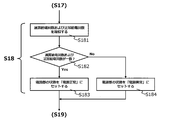
- step S18 the control unit 50 determines the state of the power supply unit 20.
- the state of the power supply unit 20 may be determined, for example, as "normal power supply” or "abnormal power supply” (described later).
- step S19 the control unit 50 causes the notification unit 60 to notify the state of the power supply unit in a different manner based on the total number of times of power supply (described later).
- FIG. 4 is a flow diagram detailing the state determination operation of the power supply unit 20 by the control unit 50 with respect to step S18.
- the control unit 50 acquires the total number of feeds and the number of normal feeds from the memory 80 in step S181, and then determines in step S182 whether the values of the total number of feeds and the number of normal feeds match. .. When these values match (step S182: Yes), the state of the power supply unit is determined to be "normal power supply” and set in step S183. On the other hand, when the normal power supply count is not counted and the total power supply count and the normal power supply count do not match (step S182: No), the state of the power supply unit is determined to be "power supply abnormality" and set in step S184. To.
- Table 1 shows an example of the relationship between the total number of power supplies and the number of normal power supplies for the state of the power supply unit determined in step S18.
- the information as shown in Table 1 is stored in the database in the memory 80 in a table format together with the time, and it is preferable that the record is inserted every time the data is updated.
- these data are stored as power usage history information.
- the notification operation by the notification unit 60 in step S19 following step S18 is preferably configured to notify the state of the power supply unit in a different manner based on the total number of times of power supply. For example, when the state of the power supply unit 20 is determined to be "normal power supply" in step S18, the notification unit 60 lights one or a plurality of LEDs in white, and at that time, the larger the total number of times of power supply, the darker the LEDs. It is preferable that the number of LEDs to be lit in color or to be lit is reduced. As a result, the user can intuitively grasp the battery life of the power supply unit 20.
- the notification unit 60 may give a notification according to the range of the total power supply count (N). Specifically, when 1 ⁇ N ⁇ 100, the LED is turned red, and similarly, when 100 ⁇ N ⁇ 1000, it turns yellow, and when 1000 ⁇ N ⁇ 10000, it turns purple, 10,000. When ⁇ N, the LED is turned on in blue. This is based on the finding that when the state of the power supply unit 20 is determined to be "power supply abnormality", the smaller the value of the total number of power feeds (N), the more severe the abnormal state.
- the range of the total number of times of power supply may be further subdivided.
- the range of the total number of power feeds and the corresponding notification mode may be configured to be configurable and stored in the memory 80 as a notification rule.
- the user can intuitively grasp the state of the power supply unit 20.
- the notification mode based on the total number of times of power supply, for example, even when the state of the power supply unit 20 is "normal power supply”, not only that fact but also the battery life is gradually approaching. Can be perceived by the user.
- the state of the power supply unit 20 is "power supply abnormality”
- the user can perceive the severity of the abnormal state. This also leads to improvement in convenience regarding repair of the suction device 10. For example, when a user makes an inquiry about an abnormal condition to a manufacturer, the manufacturer simply informs the LED emission mode (for example, emission color), and the manufacturer immediately determines whether repair is possible or not, and guides the user immediately. You will be able to do it.
- step S21 the control unit 50 refers to the power supply usage history information stored in the memory 80 as to whether the state of the power supply unit 20 determined in step S18 is "power supply abnormality". To identify.
- step S21: Yes the state of the power supply unit 20 is "power supply abnormality" (step S21: Yes)
- step S22 the control unit 50 stores the information as power supply abnormality information in the memory 80.
- the power supply abnormality information a part of the above-mentioned power supply usage history information may be used.
- the power supply abnormality information is configured to include the total number of power supplies, the number of normal power supplies, the state of the power supply unit 20, the time when the state of the power supply unit 20 is specified, and the like included in the power supply usage history information. Is good.
- the power supply abnormality information may include a corresponding assumed failure code and contents that are assumed from the total number of times of power supply. As for the assumed failure code and the contents, the master information is stored in the memory 80 as defined in advance.
- the maintenance company and / or the repair company of the suction device 10 can refer to the contents recorded in the memory 80 of the suction device 10 to the suction device 10.
- the details of the failure that has occurred can be easily identified. That is, it is possible to quickly deal with failures, including shortening the repair time.
- the control unit 50 controls the power supply unit 20 so as to prohibit at least the power supply operation by the power supply unit 20 while the power supply abnormality information is stored in the memory 80.
- the flag indicating that the power feeding operation by the power supply unit 20 is "invalid” is also stored in the memory 80 as a part of the power supply abnormality information.
- the control unit 50 is configured to refer to the flag each time the power supply unit 20 is to perform the power supply operation, and to control so as to prohibit the power supply operation when the flag indicates "invalid". Good.
- control unit 50 not only makes it possible to determine that the power supply unit 20 is in the "normal power supply” or "abnormal power supply” state when performing the power supply operation, but also particularly when the power supply is abnormal.
- the power supply operation by the power supply unit 20 is prohibited.
- the power supply unit 20 cannot perform the power feeding operation. That is, the safety of the suction device 10 can be enhanced, and the user can use the suction device 10 more safely.
- FIG. 5 shows a flow in which the power supply operation of the power supply unit 20 is prohibited by the control unit 50 when the state of the power supply unit 20 is determined to be “power supply abnormality”
- FIG. 6 shows a flow of the power supply unit 20.
- the flow for allowing the power feeding operation to be resumed by the control unit 50 after the power feeding operation is once prohibited is shown.
- the suction device 10 is newly made operable after dealing with the power supply unit 20 in an abnormal state (for example, repairing or replacing the battery)
- the operation shown in the flow chart of FIG. 6 is performed. Is good.
- the operation of FIG. 6 should be performed together with the above-mentioned initialization process.
- the operation of FIG. 6 may be performed after the initialization process is completed and before the start of the process after step S12 of FIG.
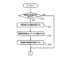
- step S31 the control unit 50 specifies that the power supply operation of the power supply unit 20 is prohibited. This identification is performed by referring to the power supply abnormality information stored in the memory 80. In particular, it is carried out by identifying whether the corresponding power supply abnormality information exists in the memory 80. As a result, when the power feeding operation of the power supply unit 20 is prohibited (step S31: Yes), in step S32, the control unit 50 connects the suction device 10 to the external device via the external connection terminal 22 (for example,). Detects that it is connected via USB).
- step S33 the control unit 50 deletes the power supply abnormality information from the memory 80.
- the access right is set so that the power supply abnormality information can be deleted only through the instruction from the external device detected in step S32.
- the flag indicating that the power supply operation by the power supply unit 20, which is a part of the power supply abnormality information, is "invalid" is cleared.
- the deletion here includes not only physically deleting the data from the memory 80, but also logically deleting the data from the database, deactivating the data with a flag, and the like.
- the control unit 50 is prohibited in step S34 in response to the fact that the power supply abnormality information is deleted from the memory 80 in step S33 and the flag indicating that the power supply operation by the power supply unit 20 is "invalid" is cleared.
- the power supply operation of the power supply unit 20 is permitted again to the power supply unit 20.
- step S31: No when the power feeding operation of the power supply unit 20 is not prohibited (step S31: No), it is not necessary to perform the operations of steps S32 to S34 described above, and the control unit 50 is shown in the flow chart of FIG. The operation may be terminated as it is.
- step S34 after the power supply operation is permitted in step S34, or when the power supply operation of the power supply unit 20 is not prohibited in step S31 (step S31: No), the control unit 50 continues to be described in FIG. It is preferable to carry out the operation after step S12 shown in. If the power feeding operation is permitted in step S34, the control unit 50 may also perform the above-mentioned initialization process again.
- the operation condition is an instruction from an external device. That is, it is not possible to enable the power supply unit 20 to perform the power supply operation again simply by the user operating the suction device 10. As a result, the safety of the suction device 10 and the convenience of the user can be enhanced, and the user can use the suction device 10 more safely.
- the control unit 50 is based on whether the values of the total number of power supplies and the number of normal power supplies match, and if they do not match, the power supply unit 50.
- the state of 20 is determined to be "power supply abnormality" (steps S18 in FIG. 3 and steps S181 to S184 in FIG. 4).
- the normal power supply frequency is not counted when the voltage value of the power supply unit 20 becomes less than a predetermined power supply threshold value during the power supply operation (steps S14 and S16 in FIG. 3).
- the control unit 50 states the power supply unit according to the flow charts shown in the modified examples of FIGS. 7 and 8. May be configured to determine.
- steps S18a and S18b of the modified examples of FIGS. 7 and 8 the operations of steps S181, S183, and S184 are all the same as those shown in FIG. 4, and the description thereof will be omitted.
- a modification example step S182a in FIG. 7 and step S182b in FIG. 8 corresponding to the determination operation in step S182 in FIG. 4 will be described.
- step S182a the control unit 50 determines whether the difference between the total number of times of energization and the number of times of normal power supply (non-counting number) has reached a predetermined threshold number. That is, when the voltage V batt of the power supply unit 20 becomes less than the voltage threshold value and the number of normal feedings is not counted over a plurality of times and the number of non-counting times reaches a predetermined threshold number (step S182a: No). , The state of the power supply unit 20 is determined to be "power supply abnormality".
- the threshold number is set to "3". That is, when the number of non-counting counts reaches "3", the state of the power supply unit 20 is determined to be "power supply abnormality" for the first time. More specifically, when the total number of times of power supply is from 1 to 52, the number of times of normal power supply is similarly counted, and the state of the power supply unit 20 is determined to be "normal power supply”. When the total number of times of power supply is 53, the number of times of normal power supply is 52, and since it was not counted, the number of non-counting times is counted as one. However, since the number of non-counting times (1 time) has not yet reached the threshold number of "3" times, the state of the power supply unit 20 is still determined to be "normal power supply”.
- the normal power supply state is also counted, and the number of non-counting times remains 1 time.
- the state of the power supply unit 20 is still determined to be "normal power supply” (because the number of non-counting times has not reached "3" times).
- the total number of times of power supply reaches 93, the number of times of normal power supply remains 90 times and is not counted.
- the number of non-counting times reaches 3 times.
- the state of the power supply unit 20 is "power supply”. It will be judged as "abnormal".
- step S182b the control unit 50 stores the total number of times of power supply and the number of times of normal power supply in association with each other in the memory 80. Then, the control unit 50 determines whether the difference between the total number of feeds and the number of normal feeds (continuous non-counting number) reaches a predetermined threshold number without counting the number of normal feeds continuously over a plurality of times.
- step S182b:: In No the state of the power supply unit 20 is determined to be "power supply abnormality".
- the fact that the normal power supply count is not measured “continuously” means that the event that the voltage V batt of the power supply unit 20 becomes less than the voltage threshold value occurs during one power supply operation and the next one power supply. It corresponds to the continuous occurrence during operation.
- the power supply operation here is an operation in which the user presses the power button 13 to supply power from the power supply unit 20 to the heating unit 40 for a predetermined period of time.
- the threshold number is set to "3" times. That is, when the number of continuous non-counts reaches "3", the state of the power supply unit 20 is determined to be "power supply abnormality" for the first time. More specifically, when the total number of times of power supply is from 1 to 52, the number of times of normal power supply is similarly counted, and the state of the power supply unit 20 is determined to be "normal power supply”. When the total number of times of power supply is 53, the number of times of normal power supply is 52 times, and since it was not counted, the number of times of continuous non-counting is one.
- the state of the power supply unit 20 is still determined to be "normal power supply”. Then, since the normal power supply count is counted to 53 when the total power supply count is 54, the continuous non-counting count is reset to 0 again.
- the normal power supply state is also counted, and the number of continuous non-counting times remains 0.
- the number of normal feedings was 90 and was not counted. That is, when the total number of times of power supply is 93, the number of continuous non-counting times is 2.
- the state of the power supply unit 20 is still determined to be "normal power supply” (since the number of consecutive non-counts has not yet reached "3" times). Since the normal power supply count was counted to 91 when the total power supply count was the next 94 times, the continuous non-counting count is reset to 0 again.
- the normal power supply state is also counted, and the continuous non-counting number remains 0 times.
- the next total number of times of power supply was 219 to 221 times, the number of times of normal power supply was 215 times and was not counted. That is, when the total number of times of power supply is 221 times, the number of consecutive non-counts is 3 times, which means that the threshold number is reached.
- the state of the power supply unit 20 is determined to be "power supply abnormality".
- control unit 50 causes the notification unit 60 to notify the state of the power supply unit 20 in a different manner based on the total number of times of power supply (step S19), and then.
- the state of the power supply unit 20 is "power supply abnormality"
- the power supply operation of the power supply unit 20 is prohibited (step S23).
- the control unit 50 may be configured to control the power supply operation of the power supply unit 20 in a different manner based on the total number of times of power supply.
- the control unit 50 considers that the power supply unit 20 has a serious problem such as damage to the battery cell due to dropping or impact, and the battery is replaced. The operation of the power supply unit 20 may be stopped so that the power is not permanently supplied until the power supply is performed. Further, in the case of 10000 ⁇ N, the control unit 50 may consider that the problem of battery life due to aging deterioration or the like has occurred, and may not dare to stop the operation of the power supply unit 20. This makes it possible to provide the inhalation device 10 with further consideration for safety and convenience to the user.
- the notification operation (step S19) of the notification unit 60 of the suction device 10 is configured to emit different colors by using one or a plurality of LEDs. It was supposed to be.
- the mode of notification is not limited to this, and any mode may be used as long as it operates to give explicit notification to the user. Specifically, it can be realized by light emission, display, vocalization, vibration, and a combination thereof. As a result, a flexible notification mode for the user can be realized.
- the notification unit 60 may include one or more vibrators, and may be configured to generate vibrations of one or more vibration types based on the range of the counted total number of times of feeding.
- the notification unit 60 may include one or more speakers and may be configured to generate sound based on a range of counted total feed count values.
- the notification unit 60 may include one or more displays, and may be configured to display on the display based on the range of the counted total number of feeds.
- the control unit 50 may also display at least a part of the power supply abnormality information (for example, the above-mentioned abnormality code) on the display.
- the suction device 100 according to the second embodiment will be described below with reference to FIG.
- the configurations and functions already described in relation to the first embodiment are designated by substantially the same reference numerals, and detailed description thereof will be omitted.
- the suction device 100 of the present embodiment when the sensor 70 (for example, the suction sensor) detects the start of a series of suction operations by the user (for example, eight times), the suction device 100 is turned on and the power is supplied. The power feeding operation by the unit 20 is started, and the aerosol is generated. This power feeding operation is performed until the sensor 70 detects the end of a series of suction operations.
- FIG. 9 is a schematic block diagram of the configuration of the suction device 100 according to the second embodiment.
- the suction device 100 includes a first member 102, a second member 104, and a third member 126, and the entire structure is configured by mounting these members.
- the second member 104 is detachably fitted into the first member 102
- the third member 126 is detachably fitted into the second member 104.
- the second member 104 is a suction article containing an aerosol source
- the third member 126 is a suction article containing a flavor source.
- the first member 102 may be a power supply unit used for the suction device 100, and includes a power supply unit 20, a control unit 50, a notification unit 60, a sensor 70, a memory 80, and a connection unit (not shown), and is electric. Is connected.
- the suction article (accommodating the aerosol source), which is the second member 104, may be a cartridge and includes a reservoir 116, an atomizing section 118, an air intake flow path 120, and an aerosol flow path 121.
- the suction article (containing the flavor source), which is the third member 126, may be a capsule and includes a flavor source holding portion 128 and a mouthpiece portion 122.
- the flavor source holding portion 128 may contain a flavor component contained in the cigarette.
- the control unit 50 determines the state of the power supply unit 20 based on the total number of times of power supply and the number of normal power supplies counted according to the power supply operation of the power supply unit 20.
- the number of normal power feeds is counted when the voltage value of the power supply unit 20 is equal to or higher than a predetermined voltage threshold value through the power supply operation.
- the control unit 50 of the power supply unit is normal in the power supply unit when the power supply unit is used, especially when the battery is discharged during the suction operation by the user.
- the abnormal state can be appropriately grasped.
- control unit 50 determines that the state of the power supply unit 20 is "power supply abnormality" when the normal power supply count is not counted and the total power supply count and the normal power supply count do not match. Then, the control unit 50 stores the power supply abnormality information in the memory 80 when the state of the power supply unit 20 is determined to be "power supply abnormality", and the power supply operation by the power supply unit 20 according to the storage of the power supply abnormality information. Is prohibited. Further, the control unit 50 deletes the power supply abnormality information stored in the memory 80 from the memory 80 in response to an instruction from an external device (not shown) connected to the power supply unit, and responds to the deletion of the power supply abnormality information. , Allow prohibited power supply operations.
- the control unit 50 of the power supply unit determines the abnormal state of the power supply unit during battery discharge. It can be determined with certainty. Further, by prohibiting the power supply operation by the power supply unit 20, the safety for the user can be enhanced. Further, by requiring an instruction from an external device for deleting the power supply abnormality information, it is possible to prevent the suction operation from malfunctioning due to the user's erroneous operation and enhance the safety to the user. In addition, the convenience of the user can be enhanced by allowing the once prohibited power feeding operation to be permitted again.
- the notification unit 60 operates so as to give an explicit notification to the user. Specifically, the notification unit 60 notifies the user in various modes by light emission, display, vocalization, vibration, and a combination thereof, as necessary.
- the notification unit 60 may include one or more LEDs, and may be configured to emit light in one or more colors depending on the determined state of the power supply unit 20.
- the notification unit 60 is configured to notify the status of the power supply unit 20. For example, it is preferable to notify whether the power supply unit 20 is in a normal state or an abnormal state, and further notify the state of the power supply unit 20 in different modes based on the total number of times of power supply. That is, the user during the suction operation can intuitively grasp the normal or abnormal state of the power supply unit when the battery is discharged by perceiving the notification mode. In addition, the convenience of repairing the power supply unit can be improved.
- the sensor 70 is composed of various sensors.
- the sensor 70 is configured to detect the voltage value of the power supply unit 20 over the discharge state (that is, the power feeding operation to the atomization unit 118).
- the sensor 70 is also configured to include a suction sensor, such as a microphone capacitor, to detect a suction action by the user and, in particular, to identify the start and end of a series of suction actions by the user.
- connection portion may be an external connection terminal (22) as in the first embodiment, and when connected to the external device, the suction device 100 stored in the memory 80 based on a command from the external device. It should be configured so that various setting data and / or firmware can be rewritten.
- the reservoir 116 holds the aerosol source.
- the reservoir 116 is composed of a fibrous or porous material and holds an aerosol source as a liquid in the gaps between the fibers and in the pores of the porous material.
- fibrous or porous material for example, cotton, glass fiber, tobacco raw material, or the like can be used.
- the reservoir 116 may be configured as a tank for containing the liquid.
- the reservoir 116 may have a configuration capable of replenishing the consumed aerosol source.
- the reservoir 116 may be configured so that the reservoir 116 itself can be replaced when the aerosol source is consumed.
- the aerosol source is not limited to a liquid, but may be a solid. When the aerosol source is a solid, the reservoir 116 may be, for example, a hollow container without a fibrous or porous material.
- the atomizing unit 118 is configured to generate an aerosol from an aerosol source. Specifically, the atomizing unit 118 produces an aerosol by atomizing or vaporizing the aerosol source.
- the suction device 100 is a medical inhaler such as a nebulizer
- the atomizing unit 118 produces an aerosol by atomizing or vaporizing an aerosol source containing a drug.
- the atomizing unit 118 receives the electric power supplied from the power supply unit 20 to generate an aerosol.
- a wick (not shown) may be provided to connect the reservoir 116 and the atomizing section 118. In this case, a portion of the wick passes through the interior of the reservoir 116 and contacts the aerosol source.
- the other part of the wick extends to the atomization section 118.
- the aerosol source is carried from the reservoir 116 to the atomizer 118 by the wick's capillary effect.
- the atomizing unit 118 includes a heater electrically connected to the power supply unit 20. The heater is placed in contact with or in close proximity to the wick.
- the control unit 50 controls the heater of the atomizing unit 118 and atomizes the aerosol source by heating the aerosol source carried through the wick.
- Another example of the atomizing unit 118 may be an ultrasonic atomizer that atomizes an aerosol source by ultrasonic vibration.
- the cartridge which is the second member 104, is formed with a vent for allowing air to flow into the reservoir 116. Then, the air intake flow path 120 connected from the vent is connected to the atomizing unit 118, and the air intake flow path 120 leads to the outside of the suction device 100.
- the aerosol produced in the atomizing section 118 is mixed with the air taken in through the air intake flow path 120.
- the mixed fluid of aerosol and air is pumped into the aerosol flow path 121, as indicated by arrow 124.
- the aerosol flow path 121 extends over the second member 104 and the third member 126, and transports the mixed fluid of aerosol and air generated in the atomizing portion 118 to the mouthpiece 122 of the third member 126.
- the flavor source holding portion 128 is a component for imparting flavor to the aerosol.
- the flavor source holding portion 128 is arranged in the middle of the aerosol flow path 121.
- the mixed fluid of aerosol and air generated by the atomizing unit 118 (hereinafter, the mixed fluid may be simply referred to as aerosol) flows through the aerosol flow path 121 to the mouthpiece 122.
- the flavor source holding portion 128 is provided downstream of the atomizing portion 118 with respect to the flow of the aerosol.
- the flavor source holding portion 128 is located closer to the mouthpiece 122 in the aerosol flow path 121 than the atomizing portion 118. Therefore, the aerosol produced by the atomizing unit 118 passes through the flavor source holding unit 128 and then reaches the mouthpiece 122. When the aerosol passes through the flavor source holding portion 128, the flavor component contained in the flavor source holding portion 128 is imparted to the aerosol.
- the flavor source holding unit 128 may be derived from tobacco, such as a processed product obtained by molding chopped tobacco or a tobacco raw material into a granular, sheet-like or powder-like form.
- the flavor source holder 128 may also be of non-tobacco origin made from plants other than tobacco (eg, mint, herbs, etc.).
- the flavor source holding portion 128 contains a nicotine component.
- the flavor source holding portion 128 may contain a fragrance component such as menthol.
- the reservoir 116 may also have a substance containing a flavor component.
- the suction device 100 may be configured to hold a tobacco-derived flavoring substance in the flavor source holding portion 128 and to include a non-tobacco-derived flavoring substance in the reservoir 116.
- control unit 50 is based on whether the values of the total number of power supplies and the number of normal power supplies match, and if they do not match, the power supply unit 20
- the configuration is such that the state is determined to be "power supply error".
- the normal power supply frequency is not counted when the voltage value of the power supply unit 20 becomes less than a predetermined power supply threshold value during the power supply operation.
- control unit 50 shows in each of the modified examples of FIGS. 7 and 8 shown in the first embodiment, instead of simply determining whether the values of the total number of times of power supply and the number of times of normal power supply match.
- the state of the power supply unit 20 may be determined in the same manner as in the flow chart.
- the control unit 50 determines whether the difference between the total number of times of energization and the number of times of normal power supply (non-counting number) has reached a predetermined threshold number. That is, when the voltage V batt of the power supply unit 20 becomes less than the voltage threshold value, the normal power supply number is not counted over a plurality of times, and the non-counting number reaches a predetermined threshold number, the state of the power supply unit 20 Is determined to be "power supply error".
- the control unit 50 stores the total number of times of power supply and the number of times of normal power supply in association with each other in the memory 80. Then, the control unit 50 determines whether the difference between the total number of feeds and the number of normal feeds (continuous non-counting number) reaches a predetermined threshold number without counting the number of normal feeds continuously over a plurality of times. That is, when the voltage V batt of the power supply unit 20 becomes less than the voltage threshold value, the normal power supply count is not continuously counted over a plurality of times, and the continuous non-counting count reaches a predetermined threshold value. The state of 20 is determined to be "power supply abnormality".
- the fact that the normal power supply count is not measured “continuously” means that the event that the voltage V batt of the power supply unit 20 becomes less than the voltage threshold value occurs during one power supply operation and the next one power supply. It corresponds to the continuous occurrence during operation.
- the power supply operation here is an operation in which the user performs a series of suction operations to supply electric power from the power supply unit 20 to the heating unit 40 over a period from the start to the end of the series of suction operations. That is.
- control unit 50 of the power supply unit determines more accurately the abnormal state of the power supply unit when the battery is discharged. Can be done.
- suction devices, power supply units, and methods according to some embodiments have been described with reference to the drawings. It is understood that the present disclosure, when executed by a processor, can also be implemented as a program that causes the processor to execute a method of operating a suction device, or as a computer-readable storage medium containing the program.
Abstract
Provided is an inhalation device that appropriately ascertains the state of a power supply part and, in particular, quickly and reliably detects said state when a power supply abnormality has occurred during battery discharge. An inhalation device that generates an aerosol and comprises a heating part that atomizes an aerosol source, a power supply part that performs an operation that supplies power to the heating part, a sensor that detects a voltage value for the power supply part, a control part that determines the state of the power supply part on the basis of a total power supply count and a normal power supply count that are tallied in accordance with the power supply operation, the normal power supply count being tallied when the voltage value for the power supply part is at or above a prescribed voltage threshold value throughout the power supply operation, and a notification part that gives notification of the state of the power supply part.
Description
本開示は、吸引装置、電源ユニット、及び方法に関する。具体的には、エアロゾルを生成する吸引装置、吸引装置に使用される電源ユニット、及びエアロゾルを生成する吸引装置を動作させる方法に関する。
This disclosure relates to a suction device, a power supply unit, and a method. Specifically, the present invention relates to a suction device for generating an aerosol, a power supply unit used for the suction device, and a method for operating a suction device for generating an aerosol.
従来、香味が付与されたエアロゾルのような吸引成分を生成する電子シガレットのような吸引装置を含む電子機器が知られている。このような電子機器のバッテリには、リチウムイオン電池が採用されることが多い。そして、リチウムイオン電池には、例えば、経年劣化等が原因で不具合が生じる場合がある。そのため、バッテリに関連した不具合が生じた場合に、その旨を検知する電子機器が存在する。
Conventionally, electronic devices including a suction device such as an electronic cigarette that produces a suction component such as a flavored aerosol are known. Lithium-ion batteries are often used as batteries for such electronic devices. Then, the lithium ion battery may have a problem due to deterioration over time, for example. Therefore, when a problem related to the battery occurs, there is an electronic device that detects the fact.
特許文献1には、ユーザが吸引装置を使用している時(バッテリ放電時)において、電源電圧が閾値電圧よりも下回った場合に、電池にエラーが発生したものと判断してその回数を計数することが開示されている。ここでは、回数が所定の閾値を超えた場合に、電池の交換が必要である旨が、交換インジケータの起動を通じて発信される。
In Patent Document 1, when the user is using the suction device (when the battery is discharged), when the power supply voltage falls below the threshold voltage, it is determined that an error has occurred in the battery and the number of times is counted. It is disclosed to do. Here, when the number of times exceeds a predetermined threshold value, the fact that the battery needs to be replaced is transmitted through the activation of the replacement indicator.
バッテリ放電時に不具合が発生した場合には、電子機器は電源異常の検知のみならず、より詳細な情報を取得することが望ましい。具体的には、突発的な電池の故障に伴うものか、或いは、電池寿命のような経年に伴うものかといった要因を特定し、そのような情報を含む診断情報をユーザに分かりやすく提示することが望ましい。特に、吸引装置においては、電源からの電力供給に応じてエアロゾル源を加熱することを伴うので、安全性の面からも、電源異常の検知のみならず、より詳細な情報も取得すべきである。
If a problem occurs when the battery is discharged, it is desirable that the electronic device not only detect the power supply abnormality but also acquire more detailed information. Specifically, it is necessary to identify factors such as whether it is due to a sudden battery failure or due to aging such as battery life, and to present diagnostic information including such information to the user in an easy-to-understand manner. Is desirable. In particular, in the suction device, since the aerosol source is heated according to the power supply from the power supply, not only the detection of the power supply abnormality but also more detailed information should be obtained from the viewpoint of safety. ..
本開示はこの点に鑑みてなされたものである。すなわち、本開示は、吸引装置の使用に関し、バッテリを具備する電源部の状態を適切に把握して、ユーザに通知することを目的の1つとする。特に、バッテリ放電時に不具合が発生したような場合に、吸引装置が電源異常の状態を判定することを目的の1つとする。また、判定される電源異常に応じて、吸引装置の動作を適切に制御することを目的の1つとする。更に、電源異常と判定される場合には、電源異常の程度及び要因を特定する診断情報を出力し、電源異常へのユーザ対処を催促することを目的の1つとする。
This disclosure has been made in view of this point. That is, one of the purposes of the present disclosure is to appropriately grasp the state of the power supply unit including the battery and notify the user of the use of the suction device. In particular, one of the purposes is for the suction device to determine the state of power failure when a problem occurs when the battery is discharged. Another object of the present invention is to appropriately control the operation of the suction device according to the determined power supply abnormality. Further, when it is determined that the power supply is abnormal, one of the purposes is to output diagnostic information for identifying the degree and cause of the power supply abnormality and to urge the user to deal with the power supply abnormality.
第1観点において、エアロゾルを生成する吸引装置が提供される。かかる吸引装置は、エアロゾル源を霧化する加熱部と、加熱部への給電動作を実施する電源部と、電源部の電圧値を検知するセンサと、給電動作にしたがって計数される通算給電回数及び正常給電回数に基づいて、電源部の状態を判定する制御部であって、正常給電回数は、給電動作を通じて電源部の電圧値が所定の電圧閾値以上である場合に計数される、制御部と、電源部の状態を通知する通知部と、を備える。当該吸引装置は、通算給電回数及び正常給電回数という2つのパラメータを用いることにより、吸引装置の使用時、特に、ユーザによる吸引動作中のバッテリ放電時の電源部の正常又は異常の状態を適切に把握し、ユーザに通知することができる。
From the first aspect, a suction device that produces an aerosol is provided. Such a suction device includes a heating unit that atomizes the aerosol source, a power supply unit that performs a power supply operation to the heating unit, a sensor that detects the voltage value of the power supply unit, and a total number of power supply counts according to the power supply operation. A control unit that determines the state of the power supply unit based on the number of normal power supplies, and the number of normal power supplies is counted when the voltage value of the power supply unit is equal to or higher than a predetermined voltage threshold value through the power supply operation. , A notification unit for notifying the status of the power supply unit. By using two parameters, the total number of times of power supply and the number of times of normal power supply, the suction device appropriately determines the normal or abnormal state of the power supply unit when the suction device is used, especially when the battery is discharged during the suction operation by the user. It can be grasped and notified to the user.
第2観点の吸引装置は、第1観点の吸引装置において、通知部が、通算給電回数に基づいて、電源部の状態を異なる態様で通知する。当該吸引装置を使用しているユーザは、通知態様を知覚することにより、バッテリ放電時の電源部の正常又は異常の状態を直感的に把握することができる。また、当該吸引装置の修理に関する利便性を向上させることができる。
In the suction device of the second viewpoint, in the suction device of the first viewpoint, the notification unit notifies the state of the power supply unit in a different manner based on the total number of times of power supply. The user using the suction device can intuitively grasp the normal or abnormal state of the power supply unit when the battery is discharged by perceiving the notification mode. In addition, the convenience of repairing the suction device can be improved.
第3観点の吸引装置は、第1観点又は第2観点の吸引装置において、制御部は、正常給電回数が計数されずに通算給電回数と正常給電回数とが一致しない場合に、電源部の状態が電源異常であると判定する。当該吸引装置の制御部は、通算給電回数及び正常給電回数という2つのパラメータを用いることにより、バッテリ放電時に不具合が発生したような場合に、バッテリ放電時の電源部の異常状態を確実に判定することができる。
The suction device of the third viewpoint is the state of the power supply unit in the suction device of the first viewpoint or the second viewpoint when the control unit does not count the normal power supply count and the total power supply count and the normal power supply count do not match. Determines that the power supply is abnormal. By using two parameters, the total number of times of power supply and the number of times of normal power supply, the control unit of the suction device reliably determines the abnormal state of the power supply unit during battery discharge when a problem occurs during battery discharge. be able to.
第4観点の吸引装置は、第1観点から第3観点の何れかの吸引装置において、制御部は、複数回数にわたり正常給電回数が計数されずに通算給電回数と正常給電回数との差が所定の閾値回数に達する場合に、電源部の状態が電源異常であると判定する。これにより、当該吸引装置の制御部は、バッテリ放電時の電源部の異常状態を更に精度よく判定することができる。
In the suction device of the fourth aspect, in any of the suction devices of the first to the third viewpoints, the control unit does not count the number of normal feeds over a plurality of times, and the difference between the total number of feeds and the number of normal feeds is predetermined. When the threshold number of times is reached, it is determined that the state of the power supply unit is abnormal. As a result, the control unit of the suction device can more accurately determine the abnormal state of the power supply unit when the battery is discharged.
第5観点の吸引装置は、第1観点から第4観点の何れかの吸引装置において、通算給電回数と正常給電回数とが関連付けられており、制御部は、正常給電回数が連続して複数回数にわたり計数されずに通算給電回数と正常給電回数との差が所定の閾値回数に達する場合に、電源部の状態が電源異常であると判定する。これにより、当該吸引装置の制御部は、バッテリ放電時の電源部の異常状態を更に精度よく判定することができる。
In the suction device of the fifth aspect, the total number of times of feeding and the number of normal feedings are associated with each other in any of the suction devices of the first to the fourth viewpoints, and the control unit continuously performs a plurality of times of normal feeding. When the difference between the total number of times of power supply and the number of times of normal power supply reaches a predetermined threshold number without being counted over, it is determined that the state of the power supply unit is abnormal. As a result, the control unit of the suction device can more accurately determine the abnormal state of the power supply unit when the battery is discharged.
第6観点の吸引装置において、第1観点から第5観点の何れかの吸引装置において、制御部は、電源部の状態が電源異常であると判定される場合に電源異常情報をメモリに格納し、電源異常情報の格納に応じて、電源部による給電動作を禁止する。当該吸引装置の制御部は、電源部による給電動作を禁止することにより、ユーザへの安全性を高めることができる。
In the suction device of the sixth viewpoint, in any of the suction devices of the first to fifth viewpoints, the control unit stores the power supply abnormality information in the memory when the state of the power supply unit is determined to be a power supply abnormality. , Prohibits power supply operation by the power supply unit according to the storage of power supply abnormality information. The control unit of the suction device can enhance the safety to the user by prohibiting the power supply operation by the power supply unit.
第7観点の吸引装置は、第6観点の吸引装置において、制御部は、更に、メモリに格納された電源異常情報を削除し、該電源異常情報の削除に応じて、禁止された給電動作を許可する。当該吸引装置の制御部は、一旦禁止された給電動作を再び許可することにより、ユーザの利便性を高めることができる。
In the suction device of the seventh aspect, in the suction device of the sixth aspect, the control unit further deletes the power supply abnormality information stored in the memory, and in response to the deletion of the power supply abnormality information, the prohibited power supply operation is performed. To give permission. The control unit of the suction device can improve the convenience of the user by re-permitting the once prohibited power feeding operation.
第8観点の吸引装置は、第7観点の吸引装置において、制御部は、当該吸引装置に接続された外部装置からの指示に応じて、電源異常情報を削除する。これにより、ユーザの誤操作による当該吸引操作の誤動作を防止し、ユーザへの安全性を高めることができる。
The suction device of the eighth viewpoint is the suction device of the seventh viewpoint, and the control unit deletes the power supply abnormality information in response to an instruction from an external device connected to the suction device. As a result, it is possible to prevent the malfunction of the suction operation due to the erroneous operation of the user and enhance the safety for the user.
第9観点の吸引装置は、第1観点から第8観点の何れかの吸引装置において、電源部による給電動作が、ユーザの電源スイッチの押下に応じて開始され、所定の時間にわたり実施される。
In the suction device of the ninth viewpoint, in any of the suction devices of the first to eighth viewpoints, the power supply operation by the power supply unit is started in response to the pressing of the power switch of the user, and is carried out for a predetermined time.
第10観点において、エアロゾルを生成する吸引装置に使用される電源ユニットが提供される。かかる電源ユニットは、エアロゾル源を霧化する加熱部と、加熱部への給電動作を実施する電源部と、電源部の電圧値を検知するセンサと、給電動作にしたがって計数される通算給電回数及び正常給電回数に基づいて、電源部の状態を判定する制御部であって、正常給電回数は、給電動作を通じて電源部の電圧値が所定の電圧閾値以上である場合に計数される、制御部と、電源部の状態を通知する通知部と、を備える。当該電源ユニットは、通算給電回数及び正常給電回数という2つのパラメータを用いることにより、電源ユニットの使用時、特に、ユーザによる吸引動作中のバッテリ放電時の電源部の正常又は異常の状態を適切に把握し、ユーザに通知することができる。
From the tenth aspect, a power supply unit used for a suction device that produces an aerosol is provided. Such a power supply unit includes a heating unit that atomizes the aerosol source, a power supply unit that performs a power supply operation to the heating unit, a sensor that detects the voltage value of the power supply unit, and a total number of power supply counts according to the power supply operation. A control unit that determines the state of the power supply unit based on the number of normal power supplies, and the number of normal power supplies is counted when the voltage value of the power supply unit is equal to or higher than a predetermined voltage threshold through the power supply operation. , A notification unit for notifying the status of the power supply unit. By using two parameters, the total number of power supplies and the number of normal power supplies, the power supply unit can appropriately determine the normal or abnormal state of the power supply unit when the power supply unit is used, especially when the battery is discharged during suction operation by the user. It can be grasped and notified to the user.
第11観点の電源ユニットは、第10観点の電源ユニットにおいて、通知部が、通算給電回数に基づいて、電源部の状態を異なる態様で通知する。吸引動作中のユーザは、通知態様を知覚することにより、バッテリ放電時の電源部の正常又は異常の状態を直感的に把握することができる。また、当該電源ユニットの修理に関する利便性を向上させることができる。
In the power supply unit of the eleventh viewpoint, in the power supply unit of the tenth viewpoint, the notification unit notifies the state of the power supply unit in a different manner based on the total number of times of power supply. The user during the suction operation can intuitively grasp the normal or abnormal state of the power supply unit when the battery is discharged by perceiving the notification mode. In addition, the convenience of repairing the power supply unit can be improved.
第12観点の電源ユニットは、第10観点又は第11観点の電源ユニットにおいて、制御部は、正常給電回数が計数されずに通算給電回数と正常給電回数とが一致しない場合に、電源部の状態が電源異常であると判定する。当該電源ユニットの制御部は、通算給電回数及び正常給電回数という2つのパラメータを用いることにより、バッテリ放電時に不具合が発生したような場合に、バッテリ放電時の電源部の異常状態を確実に判定することができる。
The power supply unit of the twelfth viewpoint is the state of the power supply unit in the tenth viewpoint or the eleventh viewpoint, when the control unit does not count the normal power supply count and the total power supply count and the normal power supply count do not match. Determines that the power supply is abnormal. The control unit of the power supply unit uses two parameters, the total number of power supplies and the number of normal power supplies, to reliably determine the abnormal state of the power supply unit during battery discharge when a problem occurs during battery discharge. be able to.
第13観点の電源ユニットは、第10観点から第12観点の何れかの電源ユニットにおいて、制御部は、複数回数にわたり正常給電回数が計数されずに通算給電回数と正常給電回数との差が所定の閾値回数に達する場合に、電源部の状態が電源異常であると判定する。これにより、当該電源ユニットの制御部は、バッテリ放電時の電源部の異常状態を更に精度よく判定することができる。
In the power supply unit of the thirteenth viewpoint, in any of the power supply units from the tenth viewpoint to the twelfth viewpoint, the control unit does not count the number of normal power supplies over a plurality of times, and the difference between the total number of power supplies and the number of normal power supplies is predetermined. When the threshold number of times is reached, it is determined that the state of the power supply unit is abnormal. As a result, the control unit of the power supply unit can more accurately determine the abnormal state of the power supply unit when the battery is discharged.
第14観点の電源ユニットは、第10観点から第13観点の何れかの電源ユニットにおいて、通算給電回数と正常給電回数とが関連付けられており、制御部は、正常給電回数が連続して複数回数にわたり計数されずに通算給電回数と正常給電回数の差が所定の閾値回数に達する場合に、電源部の状態が電源異常であると判定する。これにより、当該電源ユニットの制御部は、バッテリ放電時の電源部の異常状態を更に精度よく判定することができる。
In the power supply unit of the 14th viewpoint, the total number of times of power supply and the number of times of normal power supply are associated with each other of the power supply unit of the 10th to 13th viewpoints, and the control unit has a plurality of times of normal power supply in succession. When the difference between the total number of times of power supply and the number of times of normal power supply reaches a predetermined threshold number without being counted over, it is determined that the state of the power supply unit is abnormal. As a result, the control unit of the power supply unit can more accurately determine the abnormal state of the power supply unit when the battery is discharged.
第15観点の電源ユニットは、第10観点から第14観点の何れかの電源ユニットであって、制御部は、電源部の状態が電源異常であると判定される場合に電源異常情報をメモリに格納し、電源異常情報の格納に応じて、電源部による給電動作を禁止する。当該電源ユニットの制御部は、電源部による給電動作を禁止することにより、ユーザへの安全性を高めることができる。
The power supply unit of the fifteenth viewpoint is any power supply unit from the tenth viewpoint to the fourteenth viewpoint, and the control unit stores the power supply abnormality information in the memory when it is determined that the state of the power supply unit is abnormal. It is stored, and the power supply operation by the power supply unit is prohibited according to the storage of power supply abnormality information. The control unit of the power supply unit can enhance safety for the user by prohibiting the power supply operation by the power supply unit.
第16観点の電源ユニットは、第15観点の電源ユニットにおいて、制御部は、更に、当該電源ユニットに接続された外部装置からの指示に応じて、メモリに格納された電源異常情報を削除し、電源異常情報の削除に応じて、禁止された給電動作を許可する。当該吸引装置の制御部は、電源異常情報を削除について外部装置からの指示を必要とすることにより、ユーザの誤操作による当該吸引操作の誤動作を防止し、ユーザへの安全性を高めることができる。また、一旦禁止された給電動作を再び許可することにより、ユーザの利便性を高めることができる。
In the power supply unit of the 16th viewpoint, in the power supply unit of the 15th viewpoint, the control unit further deletes the power supply abnormality information stored in the memory in response to an instruction from an external device connected to the power supply unit. Allows prohibited power supply operations according to the deletion of power supply error information. By requiring an instruction from the external device to delete the power supply abnormality information, the control unit of the suction device can prevent the suction operation from malfunctioning due to the user's erroneous operation and enhance the safety to the user. In addition, the convenience of the user can be enhanced by re-permitting the once prohibited power feeding operation.
第17観点の電源ユニットは、第10観点から第16観点の何れかの電源ユニットにおいて、センサが吸引センサを含み、電源部による給電動作が、吸引センサによって検知される、ユーザによる一連の吸引動作の開始に応じて開始され、一連の吸引動作の終了まで実施される。
In the power supply unit of the 17th viewpoint, in any of the power supply units of the 10th to 16th viewpoints, the sensor includes a suction sensor, and the power supply operation by the power supply unit is detected by the suction sensor, and a series of suction operations by the user. It is started according to the start of, and is carried out until the end of a series of suction operations.
第18観点において、エアロゾルを生成する吸引装置を動作させる方法が提供される。かかる方法は、エアロゾル源を霧化する加熱部への給電動作を電源部に実施させるステップと、電源部の電圧値をセンサに検知させるステップと、給電動作にしたがって計数される通算給電回数及び正常給電回数に基づいて、電源部の状態を判定するステップであって、正常給電回数は、給電動作を通じて電源部の電圧値が所定の電圧閾値以上である場合に計数される、ステップと、電源部の状態を通知するステップと、を含む。当該方法は、通算給電回数及び正常給電回数という2つのパラメータを用いることにより、吸引装置の使用時、特に、ユーザによる吸引動作中のバッテリ放電時の電源部の正常又は異常の状態を適切に把握し、ユーザに通知することができる。
From the eighteenth aspect, a method of operating a suction device that produces an aerosol is provided. In such a method, a step of causing the power supply unit to perform a power supply operation to the heating unit for atomizing the aerosol source, a step of causing the sensor to detect the voltage value of the power supply unit, a total number of power supply counts counted according to the power supply operation, and normality. A step of determining the state of the power supply unit based on the number of times of power supply, and the number of times of normal power supply is counted when the voltage value of the power supply unit is equal to or higher than a predetermined voltage threshold value through the power supply operation. Includes steps to notify the status of. By using two parameters, the total number of times of power supply and the number of times of normal power supply, the method appropriately grasps the normal or abnormal state of the power supply unit when the suction device is used, especially when the battery is discharged during the suction operation by the user. And can notify the user.
第19観点の方法は、第18観点の方法において、通知するステップが、通算給電回数に基づいて、電源部の状態を異なる態様で通知することを含む。吸引動作中のユーザは、通知態様を知覚することにより、バッテリ放電時の電源部の正常又は異常の状態を直感的に把握することができる。また、吸引装置の修理に関する利便性を向上させることができる。
The method of the 19th viewpoint includes, in the method of the 18th viewpoint, the step of notifying is notifying the state of the power supply unit in a different manner based on the total number of times of power supply. The user during the suction operation can intuitively grasp the normal or abnormal state of the power supply unit when the battery is discharged by perceiving the notification mode. In addition, the convenience of repairing the suction device can be improved.
第20観点の方法は、第18観点又は第19観点の方法において、判定するステップが、正常給電回数が計数されずに、通算給電回数と正常給電回数とが一致しない場合に、電源部の状態が電源異常であると判定することを含む。通算給電回数及び正常給電回数という2つのパラメータを用いることにより、バッテリ放電時に不具合が発生したような場合に、バッテリ放電時の電源部の異常状態を確実に判定することができる。
The method of the 20th viewpoint is the state of the power supply unit in the method of the 18th viewpoint or the 19th viewpoint when the determination step is that the normal power supply count is not counted and the total power supply count and the normal power supply count do not match. Includes determining that is a power failure. By using two parameters, the total number of times of power supply and the number of times of normal power supply, it is possible to reliably determine the abnormal state of the power supply unit at the time of battery discharge when a problem occurs during battery discharge.
以下、図面を参照しながら本開示の実施形態に係る吸引装置、電源ユニット、及び方法について添付図面と共に詳しく説明する。なお、本開示の実施形態において、吸引装置は、電子たばこやネブライザを含むが、これらに限定されない。特に、吸引装置は、ユーザが吸引するエアロゾル又は香味が付与されたエアロゾルを生成するための様々な吸引装置を含み得る。また、生成される吸引成分源は、エアロゾル以外にも不可視の蒸気も含み得る。
Hereinafter, the suction device, the power supply unit, and the method according to the embodiment of the present disclosure will be described in detail together with the attached drawings with reference to the drawings. In the embodiments of the present disclosure, the suction device includes, but is not limited to, an electronic cigarette and a nebulizer. In particular, the suction device may include various suction devices for producing aerosols that the user sucks or flavored aerosols. In addition to aerosols, the generated suction component source may also contain invisible vapors.
添付図面において、同一又は類似の要素には同一又は類似の参照符号が付され、各実施形態の説明において同一又は類似の要素に関する重複する説明は省略することがある。また、各実施形態で示される特徴は、互いに矛盾しない限り他の実施形態にも適用可能である。更に、図面は模式的なものであり、必ずしも実際の寸法や比率等とは一致しない。図面相互間においても互いの寸法の関係や比率が異なる部分が含まれていることがある。
In the attached drawings, the same or similar elements are designated by the same or similar reference numerals, and duplicate explanations regarding the same or similar elements may be omitted in the description of each embodiment. In addition, the features shown in each embodiment can be applied to other embodiments as long as they do not contradict each other. Furthermore, the drawings are schematic and do not necessarily match the actual dimensions, ratios, etc. Even between drawings, parts with different dimensional relationships and ratios may be included.
<第1実施形態>
(1-1)吸引装置の基本構造
図1Aは、第1実施形態に係る吸引装置10の全体斜視図である。図1Bは、第1実施形態に係る、エアロゾル生成基材を保持した状態の吸引装置10の全体斜視図である。本実施形態において、吸引装置10は、例えば、エアロゾル源及び香味源を含む充填物等の香味発生基材を有する吸引物品15等のエアロゾル生成基材が着脱可能に装着される。装着された吸引物品15が加熱されることによって、香味を含むエアロゾルが生成される。 <First Embodiment>
(1-1) Basic Structure of Suction Device FIG. 1A is an overall perspective view of thesuction device 10 according to the first embodiment. FIG. 1B is an overall perspective view of the suction device 10 in a state of holding the aerosol-forming base material according to the first embodiment. In the present embodiment, the suction device 10 is detachably attached to, for example, an aerosol-generating base material such as a suction article 15 having a flavor-generating base material such as an aerosol source and a filler containing a flavor source. By heating the attached suction article 15, an aerosol containing a flavor is produced.
(1-1)吸引装置の基本構造
図1Aは、第1実施形態に係る吸引装置10の全体斜視図である。図1Bは、第1実施形態に係る、エアロゾル生成基材を保持した状態の吸引装置10の全体斜視図である。本実施形態において、吸引装置10は、例えば、エアロゾル源及び香味源を含む充填物等の香味発生基材を有する吸引物品15等のエアロゾル生成基材が着脱可能に装着される。装着された吸引物品15が加熱されることによって、香味を含むエアロゾルが生成される。 <First Embodiment>
(1-1) Basic Structure of Suction Device FIG. 1A is an overall perspective view of the
当業者には理解されるように、エアロゾル生成基材は吸引物品15の一例である(以下、エアロゾル生成基材を吸引物品と総称することもある。)。エアロゾル生成基材に含まれるエアロゾル源は固体であってもよいし、液体であってもよい。エアロゾル源は、例えば、グリセリン、プロピレングリコールといった多価アルコールや、水等の液体であってもよい。エアロゾル源は、加熱することによって香喫味成分を放出するたばこ原料やたばこ原料由来の抽出物を含んでいてもよい。吸引装置10がネブライザ等の医療用吸入器である場合は、エアロゾル源は、患者が吸入するための薬剤を含んでもよい。用途によっては、エアロゾル生成基材は香味源を含まなくてもよい。
As will be understood by those skilled in the art, the aerosol-producing base material is an example of the suction article 15 (hereinafter, the aerosol-producing base material may be collectively referred to as the suction article). The aerosol source contained in the aerosol-forming substrate may be a solid or a liquid. The aerosol source may be, for example, a polyhydric alcohol such as glycerin or propylene glycol, or a liquid such as water. The aerosol source may include a tobacco raw material that releases a flavor component by heating or an extract derived from the tobacco raw material. If the aspirator 10 is a medical inhaler such as a nebulizer, the aerosol source may include a drug for the patient to inhale. Depending on the application, the aerosol-forming substrate may not contain a flavor source.
図1A及び図1Bに示すように、吸引装置10は、トップハウジング11Aと、ボトムハウジング11Bと、カバー12と、電源ボタン13と、蓋部14とを有する。トップハウジング11A及びボトムハウジング11Bは、互いに接続されることで、吸引装置10の最外のハウジング11を構成する。ハウジング11は、ユーザの手に収まるようなサイズであってもよい。この場合、ユーザが吸引装置10を使用するときに、ユーザは吸引装置10を手で保持して、エアロゾルを吸引することになる。
As shown in FIGS. 1A and 1B, the suction device 10 has a top housing 11A, a bottom housing 11B, a cover 12, a power button 13, and a lid 14. The top housing 11A and the bottom housing 11B are connected to each other to form the outermost housing 11 of the suction device 10. The housing 11 may be sized to fit in the user's hands. In this case, when the user uses the suction device 10, the user holds the suction device 10 by hand and sucks the aerosol.
トップハウジング11Aは、開口(非図示)を有し、カバー12は当該開口を閉じるようにトップハウジング11Aに結合される。図1Bに示すように、カバー12は、吸引物品15を挿入可能な開口12aを有する。蓋部14は、カバー12の開口12aを開閉するように構成される。具体的には、蓋部14は、カバー12に取り付けられ、開口12aを閉じる第1位置と開口12aを開放する第2位置との間を、カバー12の表面に沿って移動可能に構成される。
The top housing 11A has an opening (not shown), and the cover 12 is coupled to the top housing 11A so as to close the opening. As shown in FIG. 1B, the cover 12 has an opening 12a into which the suction article 15 can be inserted. The lid portion 14 is configured to open and close the opening 12a of the cover 12. Specifically, the lid portion 14 is attached to the cover 12 and is configured to be movable along the surface of the cover 12 between the first position for closing the opening 12a and the second position for opening the opening 12a. ..
電源ボタン13は、吸引装置10の電源のオンとオフを切り替えるために使用される。例えば、ユーザは、図1Bに示すように吸引物品15を開口12aに挿入した状態で電源ボタン13を押下することにより、後述の電源部から加熱部に電力を一定時間にわたり供給し、吸引物品15を燃焼させずに加熱することができる。吸引物品15が加熱されると、吸引物品15に含まれるエアロゾル源からエアロゾルが発生し、香味源の香味が当該エアロゾルに取り込まれる。ユーザは、吸引装置10から突出した吸引物品15の部分(図1Bに示された部分)から吸引動作を行うことにより、香味を含むエアロゾルを吸引することができる。
The power button 13 is used to switch the power of the suction device 10 on and off. For example, as shown in FIG. 1B, the user presses the power button 13 with the suction article 15 inserted in the opening 12a to supply electric power from the power supply unit to the heating unit, which will be described later, for a certain period of time. Can be heated without burning. When the suction article 15 is heated, an aerosol is generated from the aerosol source contained in the suction article 15, and the flavor of the flavor source is incorporated into the aerosol. The user can suck the aerosol containing the flavor by performing the suction operation from the portion of the suction article 15 (the portion shown in FIG. 1B) protruding from the suction device 10.
ボトムハウジング11Bには、後述の加熱アセンブリの内部に空気を流入するために、空気を流入させるための通気口(非図示)が形成される。具体的には、通気口は、加熱アセンブリの一端部と流体連通する。
The bottom housing 11B is formed with a vent (not shown) for allowing air to flow into the inside of the heating assembly described later. Specifically, the vent is in fluid communication with one end of the heating assembly.
図1A及び図1Bに示される吸引装置10の構成は、本開示に係る吸引装置の構成の一例にすぎない。本開示に係る吸引装置10は、エアロゾル源を含む吸引物品15を加熱することによってエアロゾルを生成することができ、生成されたエアロゾル源をユーザが吸引することができるような、様々な形態で構成することができる。
The configuration of the suction device 10 shown in FIGS. 1A and 1B is only an example of the configuration of the suction device according to the present disclosure. The suction device 10 according to the present disclosure is configured in various forms such that an aerosol can be generated by heating a suction article 15 including an aerosol source, and the user can suck the generated aerosol source. can do.
(1-2)吸引装置の構成
図2は、本実施形態に係る吸引装置10の構成を概略的に示すブロック図である。吸引装置10は、電源部20、加熱部40、制御部50、通知部60、センサ70及びメモリ80を備え、電気的に接続される。 (1-2) Configuration of Suction Device FIG. 2 is a block diagram schematically showing the configuration of thesuction device 10 according to the present embodiment. The suction device 10 includes a power supply unit 20, a heating unit 40, a control unit 50, a notification unit 60, a sensor 70, and a memory 80, and is electrically connected.
図2は、本実施形態に係る吸引装置10の構成を概略的に示すブロック図である。吸引装置10は、電源部20、加熱部40、制御部50、通知部60、センサ70及びメモリ80を備え、電気的に接続される。 (1-2) Configuration of Suction Device FIG. 2 is a block diagram schematically showing the configuration of the
電源部20は、例えば、充電式バッテリ又は非充電式のバッテリであり得る電源を有する。電源部20は、加熱部40、制御部50、通知部60、センサ70及びメモリ80等の各構成要素に電力を供給する。特に、ユーザが電源ボタン13を押下することにより、所定の期間にわたって電源部20から加熱部40に電力を供給する給電動作を実施して、吸引物品15を加熱するように加熱部40を動作させる。
The power supply unit 20 has a power supply that can be, for example, a rechargeable battery or a non-rechargeable battery. The power supply unit 20 supplies electric power to each component such as the heating unit 40, the control unit 50, the notification unit 60, the sensor 70, and the memory 80. In particular, when the user presses the power button 13, a power supply operation for supplying electric power from the power supply unit 20 to the heating unit 40 is performed for a predetermined period, and the heating unit 40 is operated so as to heat the suction article 15. ..
また、吸引装置10は、外部電源(非図示)と接続可能な外部接続端子22(端子)を有してもよい。外部接続端子22は、例えばマイクロUSB(Universal Serial Bus)等のケーブルと接続することができる。電源が充電式バッテリである場合、外部接続端子22に外部電源を接続することにより、外部電源から電源に電流を流し、電源を充電することができる。
Further, the suction device 10 may have an external connection terminal 22 (terminal) that can be connected to an external power source (not shown). The external connection terminal 22 can be connected to, for example, a cable such as a micro USB (Universal Serial Bus). When the power source is a rechargeable battery, by connecting the external power source to the external connection terminal 22, a current can be passed from the external power source to the power source to charge the power source.
外部接続端子22に対し、マイクロUSB等のデータ送信ケーブルを接続することにより、吸引装置10の作動に関するデータを外部装置(非図示)との間で送受信できるようにしてもよい。具体的には、外部接続端子22を通じて外部装置と接続することにより、外部装置によって吸引装置10のメモリ80に新規のデータを格納し、また、格納されたデータの更新及び削除を可能とするように構成されてもよい。
By connecting a data transmission cable such as a micro USB to the external connection terminal 22, data related to the operation of the suction device 10 may be transmitted / received to / from an external device (not shown). Specifically, by connecting to an external device through the external connection terminal 22, new data can be stored in the memory 80 of the suction device 10 by the external device, and the stored data can be updated and deleted. It may be configured in.
加熱部40は、加熱アセンブリを有し、その内部に吸引物品15の一部を収納可能に構成され、吸引物品15へ供給する空気の流路を画定する機能、及び吸引物品15を外周又は中心から加熱する機能を有する。これにより、エアロゾル源を霧化して、香味を含むエアロゾルを生成する。
The heating unit 40 has a heating assembly, is configured to accommodate a part of the suction article 15 inside, has a function of defining a flow path of air supplied to the suction article 15, and has an outer circumference or a center of the suction article 15. Has the function of heating from. As a result, the aerosol source is atomized to produce an aerosol containing a flavor.
更に、吸引装置10は、吸引物品15を受け入れて充填物を保持可能な凹形状の保持部45を備える。加熱部40は、挿入により受け入れた吸引物品15を外周又は中心から加熱する形状を有してもよい。つまり、加熱部40は、電源部20からの電力の電力供給を通じて、保持部45に保持された香味源を含む吸引物品15の部分を加熱することができる。
Further, the suction device 10 includes a concave holding portion 45 capable of receiving the suction article 15 and holding the filling. The heating unit 40 may have a shape that heats the suction article 15 received by insertion from the outer circumference or the center. That is, the heating unit 40 can heat the portion of the suction article 15 including the flavor source held by the holding unit 45 through the power supply of electric power from the power supply unit 20.
制御部50は、電源部20、加熱部40、通知部60、センサ70、及びメモリ80等の各構成要素の動作を制御するように構成される。また、制御部50は、各構成要素との間で情報をやり取りするように構成される。制御部50は、マイクロプロセッサ又はマイクロコンピュータとして構成された電子回路モジュールとしてよい。制御部50は、メモリ80に格納されたコンピュータ実行可能命令に従って吸引装置10の動作を制御する。制御部50は、必要に応じてメモリ80からデータを読み出して該データを吸引装置10の制御に利用し、必要に応じて、発生したデータをメモリ80に格納する。
The control unit 50 is configured to control the operation of each component such as the power supply unit 20, the heating unit 40, the notification unit 60, the sensor 70, and the memory 80. Further, the control unit 50 is configured to exchange information with each component. The control unit 50 may be an electronic circuit module configured as a microprocessor or a microcomputer. The control unit 50 controls the operation of the suction device 10 according to a computer executable instruction stored in the memory 80. The control unit 50 reads data from the memory 80 as needed, uses the data for controlling the suction device 10, and stores the generated data in the memory 80 as needed.
本実施形態では、制御部50は、電源部20による加熱部40への給電動作にしたがって計数される通算給電回数及び正常給電回数に基づいて、電源部20の状態を判定するように構成される。ここでは、正常給電回数は、給電動作を通じて電源部20の電圧値が所定の電圧閾値以上である場合に計数されるように構成される。つまり、制御部50は、通算給電回数及び正常給電回数という2つのパラメータを用いることにより、吸引装置10の使用時、特に、ユーザによる吸引動作中のバッテリ放電時の電源部の正常又は異常の状態を適切に把握することができる。
In the present embodiment, the control unit 50 is configured to determine the state of the power supply unit 20 based on the total number of times of power supply and the number of normal power supplies counted according to the power supply operation of the power supply unit 20 to the heating unit 40. .. Here, the number of normal power feeds is configured to be counted when the voltage value of the power supply unit 20 is equal to or higher than a predetermined voltage threshold value through the power supply operation. That is, the control unit 50 uses two parameters, the total number of times of power supply and the number of times of normal power supply, so that the normal or abnormal state of the power supply unit when the suction device 10 is used, particularly when the battery is discharged during the suction operation by the user. Can be properly grasped.
通知部60は、ユーザに対して明示的な通知を行うように動作する。具体的には、通知部60は、必要に応じて、発光、表示、発声、振動、及びこれらの組み合わせ等によって、ユーザに対して様々な態様の通知を行う。例えば、通知部60は、1又は複数のLEDを含んでもよく、判定された電源部20の状態に応じて、1又は複数の色で発光するように構成されてもよい。本実施形態では、通知部60は、電源部20の状態を通知するように構成される。例えば、電源部20が正常状態又は異常状態であるかを通知し、更に、通算給電回数に基づいて、電源部20の状態を異なる態様で通知するように構成されるのがよい。つまり、ユーザは通知態様を知覚することにより、バッテリ放電時の電源部の正常又は異常の状態を直感的に把握することができる。また、当該吸引装置10の修理に関する利便性を向上させることができる。具体的には、例えば、ユーザが製造元に異常状態に関する問い合わせをする際に、LEDの発光態様(例えば、発光色)を伝えるだけで、製造元側では修理可能又は修理不能の決定、及びユーザへの案内を即座にすることができるようになる。
The notification unit 60 operates so as to give an explicit notification to the user. Specifically, the notification unit 60 notifies the user in various modes by light emission, display, vocalization, vibration, and a combination thereof, as necessary. For example, the notification unit 60 may include one or more LEDs, and may be configured to emit light in one or more colors depending on the determined state of the power supply unit 20. In the present embodiment, the notification unit 60 is configured to notify the state of the power supply unit 20. For example, it may be configured to notify whether the power supply unit 20 is in a normal state or an abnormal state, and further notify the state of the power supply unit 20 in a different manner based on the total number of times of power supply. That is, the user can intuitively grasp the normal or abnormal state of the power supply unit when the battery is discharged by perceiving the notification mode. In addition, the convenience of repairing the suction device 10 can be improved. Specifically, for example, when the user inquires about the abnormal state to the manufacturer, the manufacturer decides whether the LED can be repaired or cannot be repaired by simply telling the light emitting mode (for example, the light emitting color) of the LED, and the user. You will be able to get guidance immediately.
センサ70は、通気口から加熱アセンブリへの空気取込流路及び/又はエアロゾル流路内の圧力の変動を検知する圧力センサ又は流量を検知する流量センサを含んでもよい。センサ70はまた、吸引物品15におけるコンポーネントの重量を検知する重量センサを含んでもよい。センサ70はまた、エアロゾル源が液体である場合の内部液面の高さを検知するように構成されてもよい。センサ70はまた、電源部20のSOC(State of Charge,充電状態)、電源部20の放電状態、電流積算値等がまた検知及び/又は算出されてもよい。センサ70はまた、ユーザが操作可能な操作ボタン等であってもよい。本実施形態では、特に、センサ70は、放電状態(つまり、電源部20から加熱部40への給電動作)にわたる電源部20における電圧値を検知するように構成される。また、センサ70は電源ボタン13の押下を検知するように構成される。更に、センサ70は、マイクロフォン・コンデンサのような吸引センサを含むように構成され、ユーザによる吸引動作を検知し、特に、ユーザによる一連の吸引動作の開始及び終了を特定するように構成されてもよい。
The sensor 70 may include a pressure sensor that detects pressure fluctuations in the air intake flow path and / or aerosol flow path from the vent to the heating assembly or a flow rate sensor that detects the flow rate. The sensor 70 may also include a weight sensor that detects the weight of the component in the suction article 15. The sensor 70 may also be configured to detect the height of the internal liquid level when the aerosol source is a liquid. The sensor 70 may also detect and / or calculate the SOC (System of Charge, charging state) of the power supply unit 20, the discharge state of the power supply unit 20, the current integrated value, and the like. The sensor 70 may also be an operation button or the like that can be operated by the user. In this embodiment, in particular, the sensor 70 is configured to detect the voltage value in the power supply unit 20 over the discharge state (that is, the power supply operation from the power supply unit 20 to the heating unit 40). Further, the sensor 70 is configured to detect the pressing of the power button 13. Further, the sensor 70 may be configured to include a suction sensor, such as a microphone capacitor, to detect a suction action by the user and, in particular, to identify the start and end of a series of suction actions by the user. Good.
加えて、センサ70は、加熱部40(又は、加熱部40に含まれる負荷)の温度を検出するように構成される温度検出部でもよい。例えば、温度検出部は、加熱部40の負荷の抵抗値を求めるのに要する値(加熱部40の負荷を流れる電流値、加熱部40の負荷に印加される電圧値等)を検出するように構成されてもよい。加熱部40の負荷の抵抗値が温度依存性を有する場合、検出された加熱部40の負荷の抵抗値に基づいて、加熱部40の温度を推定することができる。別の例において、温度検出部は、加熱部40の温度を検出する温度センサを含んでもよい。
In addition, the sensor 70 may be a temperature detection unit configured to detect the temperature of the heating unit 40 (or the load included in the heating unit 40). For example, the temperature detection unit detects a value required to obtain the resistance value of the load of the heating unit 40 (current value flowing through the load of the heating unit 40, voltage value applied to the load of the heating unit 40, etc.). It may be configured. When the resistance value of the load of the heating unit 40 has a temperature dependence, the temperature of the heating unit 40 can be estimated based on the detected resistance value of the load of the heating unit 40. In another example, the temperature detection unit may include a temperature sensor that detects the temperature of the heating unit 40.
メモリ80は、ROM(Read Only Memory)、RAM(Random Access Memory)、フラッシュメモリ等の記憶媒体である。メモリ80は、吸引装置10の動作に関連する様々なデータを格納することができる。例えば、メモリ80は、加熱部40について予め規定された加熱プロファイルのデータを格納していてもよい。また、メモリ80はコンピュータ実行可能命令のほか、吸引装置10の制御に必要な設定データ、及びファームウェア等のプログラムが格納されてもよい。例えば、メモリ80は、通知部60の制御方法(発光、発声、振動等の態様等)、センサ70により検知された値等に関する様々なデータを格納してもよい。更に、メモリ80は後述する動作全般を吸引装置10に実行させるためのプログラムを可能し、制御部50が当該プログラムを実行する。
The memory 80 is a storage medium such as a ROM (Read Only Memory), a RAM (Random Access Memory), and a flash memory. The memory 80 can store various data related to the operation of the suction device 10. For example, the memory 80 may store data of a heating profile defined in advance for the heating unit 40. Further, the memory 80 may store computer executable instructions, setting data necessary for controlling the suction device 10, and programs such as firmware. For example, the memory 80 may store various data related to the control method of the notification unit 60 (modes such as light emission, vocalization, vibration, etc.), the value detected by the sensor 70, and the like. Further, the memory 80 enables a program for causing the suction device 10 to execute the entire operation described later, and the control unit 50 executes the program.
本実施形態では、メモリ80は、後述するように、制御部50によって計数され、電源部20の状態を判定するために用いられる通算給電回数及び正常給電回数を含む電源使用履歴情報を格納する。また、電源部20が「電源異常」であると判定される場合に、通算給電回数に基づいて特定される電源異常情報を格納する。各種情報は、テーブル形式でデータベースに登録されてもよい。
In the present embodiment, as will be described later, the memory 80 stores power supply usage history information including the total number of power supplies and the number of normal power supplies, which are counted by the control unit 50 and used to determine the state of the power supply unit 20. Further, when the power supply unit 20 is determined to be "power supply abnormality", the power supply abnormality information specified based on the total number of times of power supply is stored. Various information may be registered in the database in a table format.
(1-3)吸引装置の動作
図3から図6は、本実施形態に係る吸引装置10を動作させる方法を示した概略フロー図である。何れのフロー図における動作も、制御部50が主体となって実施される。図3及び図4は、電源部20の状態を判定して、吸引装置10の状態を「電源正常」又は「電源異常」にセットするための概略フロー図である。また、図5は、電源部20の状態が「電源異常」であると判定された場合に電源部の給電動作を禁止するための概略フロー図であり、図6は、一旦給電動作が禁止された後に、再び給電動作を許可するための概略フロー図である。 (1-3) Operation of suction device FIGS. 3 to 6 are schematic flow charts showing a method of operating thesuction device 10 according to the present embodiment. The operation in each flow diagram is mainly performed by the control unit 50. 3 and 4 are schematic flow charts for determining the state of the power supply unit 20 and setting the state of the suction device 10 to "normal power supply" or "abnormal power supply". Further, FIG. 5 is a schematic flow diagram for prohibiting the power supply operation of the power supply unit when it is determined that the state of the power supply unit 20 is “power supply abnormality”, and FIG. 6 is a schematic flow diagram for temporarily prohibiting the power supply operation. After that, it is a schematic flow diagram for permitting the power feeding operation again.
図3から図6は、本実施形態に係る吸引装置10を動作させる方法を示した概略フロー図である。何れのフロー図における動作も、制御部50が主体となって実施される。図3及び図4は、電源部20の状態を判定して、吸引装置10の状態を「電源正常」又は「電源異常」にセットするための概略フロー図である。また、図5は、電源部20の状態が「電源異常」であると判定された場合に電源部の給電動作を禁止するための概略フロー図であり、図6は、一旦給電動作が禁止された後に、再び給電動作を許可するための概略フロー図である。 (1-3) Operation of suction device FIGS. 3 to 6 are schematic flow charts showing a method of operating the
図3のフロー図に示される各動作を開始する前に、吸引装置10は、制御部50によって初期化処理が実施されている必要がある。初期化処理は、通算給電回数及び正常給電回数の値を「0」にセットすることを含む。電源部20が使用されている間は、通算給電回数及び正常給電回数の値が継続的に計数される。他方、例えば、電源部20が修理により交換されるような場合には、再度の初期化処理が実施されて通算給電回数及び正常給電回数の値が「0」にリセットされる。なお、本明細書において回数を「計数」するとは、その回数の値を+1だけインクリメントした値にセットすることを含む。
Before starting each operation shown in the flow chart of FIG. 3, the suction device 10 needs to be initialized by the control unit 50. The initialization process includes setting the values of the total number of times of power supply and the number of times of normal power supply to "0". While the power supply unit 20 is in use, the values of the total number of times of power supply and the number of times of normal power supply are continuously counted. On the other hand, for example, when the power supply unit 20 is replaced by repair, the initialization process is performed again and the values of the total number of times of power supply and the number of times of normal power supply are reset to "0". In the present specification, "counting" the number of times includes setting the value of the number of times to a value incremented by +1.
通算給電回数とは、電源部20による加熱部40への給電動作が実施された通算回数のことである。例えば、通算給電回数は、給電動作が開始される毎に、計数されるのがよい。また、正常給電回数とは、給電動作の開始から終了までを通じて、センサ70によって定期的に検知される電源部20の電圧値が所定の電圧閾値以上である状態が維持された場合に、給電動作が正常であるとして計数される回数のことである。他方、給電動作を通じて、電源部20の電圧値が一度でも所定の電圧閾値未満となった場合には、正常給電回数の値は計数されないことになる。
The total number of times of power supply is the total number of times the power supply unit 20 has performed the power supply operation to the heating unit 40. For example, the total number of times of power supply may be counted each time the power supply operation is started. The normal power supply count is the power supply operation when the voltage value of the power supply unit 20 periodically detected by the sensor 70 is maintained at or above a predetermined voltage threshold value from the start to the end of the power supply operation. Is the number of times that is counted as normal. On the other hand, if the voltage value of the power supply unit 20 becomes less than the predetermined voltage threshold value even once through the power supply operation, the value of the normal power supply count is not counted.
つまり、電源部20が正常に動作することができる期間中は、通算給電回数及び正常給電回数が共に計数されるので、各値は一致することになる。一例では、この場合に、制御部50は、電源部20の状態を「電源正常」と判定するのがよい。他方、正常給電回数が計数されることなく、通算給電回数及び正常給電回数が一致しなくなった場合には、制御部50は、電源部20の状態を「電源異常」と判定されるのがよい。このように、吸引装置10は、通算給電回数及び正常給電回数という2つのパラメータを用いて、ユーザによる吸引動作中のバッテリ放電時における電源部の正常又は異常の状態を適切に把握することができる。
That is, during the period during which the power supply unit 20 can operate normally, the total number of times of power supply and the number of times of normal power supply are both counted, so that the respective values match. In one example, in this case, the control unit 50 may determine that the state of the power supply unit 20 is "normal power supply". On the other hand, if the total number of power supplies and the number of normal power supplies do not match without counting the number of normal power supplies, the control unit 50 may determine that the state of the power supply unit 20 is "power supply abnormality". .. In this way, the suction device 10 can appropriately grasp the normal or abnormal state of the power supply unit at the time of battery discharge during the suction operation by the user by using two parameters of the total number of times of power supply and the number of times of normal power supply. ..
前述の初期化処理の後、図3に示される動作が開始される(START)と、ステップS11において、制御部50は、電源部20が給電動作を開始したかを判定する。本実施形態では、ユーザが電源ボタン13を押下するのに応じて、制御部50は、電源部20に、加熱部40への給電動作を実施させる。つまり、ステップS11では、センサ70による、電源ボタン13の押下を検知したか否が判定されるのがよい。或いは、センサ70によるユーザの吸引動作の開始を検知したか否かが判定されてもよい。
After the above-mentioned initialization process, when the operation shown in FIG. 3 is started (START), in step S11, the control unit 50 determines whether the power supply unit 20 has started the power feeding operation. In the present embodiment, in response to the user pressing the power button 13, the control unit 50 causes the power supply unit 20 to perform a power supply operation to the heating unit 40. That is, in step S11, it is preferable to determine whether or not the sensor 70 has detected the pressing of the power button 13. Alternatively, it may be determined whether or not the sensor 70 has detected the start of the suction operation of the user.
電源部20による給電動作が開始された場合(ステップS11:Yes)、給電動作が終了するまでの以降の動作では、給電動作に関する所定の条件にしたがって通算給電回数及び正常給電回数の計数を行う。つまり、ステップS12において、制御部50は、まず、メモリ80に格納されている通算給電回数を取得して計数する。具体的には、例えば、制御部50は、メモリ80から取得した通算給電回数が100の場合に、通算給電回数を101に計数する。計数された通算給電回数の値は、引き続きメモリ80に保持される。なお、給電動作が開始されていない場合(ステップS11:No)はステップS12以降の処理は実行されない。
When the power supply operation by the power supply unit 20 is started (step S11: Yes), in the subsequent operations until the power supply operation is completed, the total number of times of power supply and the number of normal power supplies are counted according to a predetermined condition regarding the power supply operation. That is, in step S12, the control unit 50 first acquires and counts the total number of power feeds stored in the memory 80. Specifically, for example, when the total number of times of power supply acquired from the memory 80 is 100, the control unit 50 counts the total number of times of power supply to 101. The counted value of the total number of power feeds is continuously held in the memory 80. If the power feeding operation has not been started (step S11: No), the processes after step S12 are not executed.
次いで、ステップS13において、制御部50は、センサ70に電源部20の電圧値Vbattを検知させることにより、電源部20の電圧値Vbattを取得する。引き続き、ステップS14において、制御部50は、取得した電圧値Vbattを用いて、メモリ80に予め格納してある電圧閾値と比較する。
Next, in step S13, the control unit 50 acquires the voltage value V batt of the power supply unit 20 by causing the sensor 70 to detect the voltage value V batt of the power supply unit 20. Subsequently, in step S14, the control unit 50 uses the acquired voltage value V batt to compare with the voltage threshold value stored in advance in the memory 80.
所得した電圧値Vbattが電圧閾値以上である場合(ステップS14:Yes)、ステップS15において、制御部50は、電源部20が給電動作を終了しているかを判定する。本実施形態では、給電動作は一定時間(例えば、150秒)にわたり実施されるので、制御部50は、ステップS11で電源部20による給電動作が開始されてから所定の時間が経過したかを判定するのがよい。
When the received voltage value V batt is equal to or higher than the voltage threshold value (step S14: Yes), in step S15, the control unit 50 determines whether the power supply unit 20 has finished the power feeding operation. In the present embodiment, the power feeding operation is performed for a certain period of time (for example, 150 seconds), so that the control unit 50 determines whether a predetermined time has elapsed since the power feeding operation by the power supply unit 20 was started in step S11. It is good to do.
電源部20が給電動作を終了していない場合(ステップS15:No)は、ステップS13に戻り、制御部50は再び電圧値Vbattを取得し、次のステップS14において電源閾値以上であるかの比較を繰り返す。当該繰り返しは、例えば、約1秒間隔で実施するように構成されるのがよい。
If the power supply unit 20 has not completed the power supply operation (step S15: No), the process returns to step S13, the control unit 50 acquires the voltage value V batt again, and whether it is equal to or higher than the power supply threshold value in the next step S14. Repeat the comparison. The repetition may be configured to be performed, for example, at intervals of about 1 second.
電源部20が給電動作を終了したと判定される場合(ステップS15:Yes)とは、給電動作を通じて電源部20の電圧値が所定の電圧閾値以上を維持できた場合であるので、制御部50は、電源部20が正常に給電動作を終了したものとみなす。次のステップS16において、制御部50は、メモリ80に格納している正常給電回数を取得して計数する。具体的には、例えば、制御部50は、メモリ80から取得した正常給電回数が100の場合に、正常給電回数を101に計数する。計数された正常給電回数の値は、引き続きメモリ80に保持される。
The case where it is determined that the power supply unit 20 has completed the power supply operation (step S15: Yes) is a case where the voltage value of the power supply unit 20 can be maintained at a predetermined voltage threshold value or higher through the power supply operation, so that the control unit 50 Deems that the power supply unit 20 has normally completed the power supply operation. In the next step S16, the control unit 50 acquires and counts the number of normal feedings stored in the memory 80. Specifically, for example, when the number of normal feedings acquired from the memory 80 is 100, the control unit 50 counts the number of normal feedings to 101. The counted value of the number of normal feedings is continuously held in the memory 80.
他方、ステップS14において電源部20の電圧値Vbattが電圧閾値未満となったと判定された場合(ステップS14:No)は、制御部50は、電源部20に何かしら不具合が生じているものとみなす。この場合は、制御部50は正常給電回数を計数しない。次いで、次のステップS17において、制御部50は、電源部20の給電動作を強制的に終了するように構成されてもよい。そのような構成により、電源部20に生じた不具合の悪化を迅速に防止することができる。
On the other hand, when it is determined in step S14 that the voltage value V batt of the power supply unit 20 is less than the voltage threshold value (step S14: No), the control unit 50 considers that the power supply unit 20 has some trouble. .. In this case, the control unit 50 does not count the number of normal feeding times. Next, in the next step S17, the control unit 50 may be configured to forcibly terminate the power feeding operation of the power supply unit 20. With such a configuration, it is possible to quickly prevent the deterioration of the defect that occurs in the power supply unit 20.
その後、ステップS18において、制御部50は、電源部20の状態を判定する。ここでは、電源部20の状態は、例えば、「電源正常」又は「電源異常」のように判別されるのがよい(後述)。次いで、ステップS19において、制御部50は、通算給電回数に基づいて、通知部60に、電源部の状態を異なる態様で通知させる(後述)。
After that, in step S18, the control unit 50 determines the state of the power supply unit 20. Here, the state of the power supply unit 20 may be determined, for example, as "normal power supply" or "abnormal power supply" (described later). Next, in step S19, the control unit 50 causes the notification unit 60 to notify the state of the power supply unit in a different manner based on the total number of times of power supply (described later).
図4は、ステップS18に関し、制御部50による電源部20の状態の判定動作を詳細化したフロー図である。具体的には、制御部50は、ステップS181において通算給電回数及び正常給電回数をメモリ80から取得し、次いで、ステップS182においてこれら通算給電回数及び正常給電回数の各値が一致するかを判定する。これらの値が一致する場合(ステップS182:Yes)は、ステップS183において、電源部の状態は「電源正常」と判定され、セットされる。他方、正常給電回数が計数されずに、通算給電回数と正常給電回数とが一致しない場合(ステップS182:No)は、ステップS184において、電源部の状態は「電源異常」と判定され、セットされる。
FIG. 4 is a flow diagram detailing the state determination operation of the power supply unit 20 by the control unit 50 with respect to step S18. Specifically, the control unit 50 acquires the total number of feeds and the number of normal feeds from the memory 80 in step S181, and then determines in step S182 whether the values of the total number of feeds and the number of normal feeds match. .. When these values match (step S182: Yes), the state of the power supply unit is determined to be "normal power supply" and set in step S183. On the other hand, when the normal power supply count is not counted and the total power supply count and the normal power supply count do not match (step S182: No), the state of the power supply unit is determined to be "power supply abnormality" and set in step S184. To.
ステップS18で判定される電源部の状態について、通算給電回数と正常給電回数との関係の例を次の表1に示す。表1のような情報は時刻と共にテーブル形式でメモリ80内のデータベースに格納され、データが更新される都度、レコードが挿入されるように構成されるのがよい。ここでは、電源使用履歴情報としてこれらのデータが格納される。
Table 1 below shows an example of the relationship between the total number of power supplies and the number of normal power supplies for the state of the power supply unit determined in step S18. The information as shown in Table 1 is stored in the database in the memory 80 in a table format together with the time, and it is preferable that the record is inserted every time the data is updated. Here, these data are stored as power usage history information.

表1の例では、通算給電回数が1回から52回までは、順次、正常給電回数も同様に計数され、電源部20の状態も「電源正常」と判定される。しかしながら、通算給電回数が53回となった場合に、正常給電回数が計数されておらず52回のままであるために、電源部の状態が「電源異常」と判定されている。なお、上記の表及びその値はあくまで例示にすぎず、メモリ80に格納される電源使用履歴情報の項目もこれに限定されないことが当業者には理解される。例えば、電源部の状態を判定した時の時刻情報も併せて履歴管理されてもよい。
In the example of Table 1, when the total number of times of power supply is from 1 to 52, the number of times of normal power supply is also counted in the same manner, and the state of the power supply unit 20 is also determined to be "normal power supply". However, when the total number of power feedings is 53, the normal number of feedings is not counted and remains 52 times, so that the state of the power supply unit is determined to be "power supply abnormality". It will be understood by those skilled in the art that the above table and its values are merely examples, and the items of power supply usage history information stored in the memory 80 are not limited thereto. For example, the time information when the state of the power supply unit is determined may also be managed in history.
ステップS18に続くステップS19の通知部60による通知動作は、通算給電回数に基づいて、電源部の状態を異なる態様で通知するように構成されるのがよい。例えば、ステップS18で電源部20の状態が「電源正常」と判定された場合、通知部60は1又は複数のLEDを白色に点灯させ、その際、通算給電回数が大きくなる程、LEDを暗い色に点灯させる、又は点灯させるLEDの個数を少なくするように構成されるのがよい。これにより、電源部20の電池寿命をユーザに直感的に把握させることができる。
The notification operation by the notification unit 60 in step S19 following step S18 is preferably configured to notify the state of the power supply unit in a different manner based on the total number of times of power supply. For example, when the state of the power supply unit 20 is determined to be "normal power supply" in step S18, the notification unit 60 lights one or a plurality of LEDs in white, and at that time, the larger the total number of times of power supply, the darker the LEDs. It is preferable that the number of LEDs to be lit in color or to be lit is reduced. As a result, the user can intuitively grasp the battery life of the power supply unit 20.
また、ステップS18で電源部20の状態が「電源異常」と判定された場合、通知部60は、通算給電回数(N)がどの範囲にあるかに応じて通知を行ってもよい。具体的には、1≦N<100の場合には、LEDを赤色に点灯させ、同様に、100≦N<1000の場合には黄色に、1000≦N<10000の場合には紫色に、10000≦Nの場合には青色にLEDを点灯させるといった具合である。これは、電源部20の状態が「電源異常」と判定される場合、通算給電回数(N)の値が小さい程、異常状態の重度も増すとの知見に基づく。
Further, when the state of the power supply unit 20 is determined to be "power supply abnormality" in step S18, the notification unit 60 may give a notification according to the range of the total power supply count (N). Specifically, when 1 ≦ N <100, the LED is turned red, and similarly, when 100 ≦ N <1000, it turns yellow, and when 1000 ≦ N <10000, it turns purple, 10,000. When ≦ N, the LED is turned on in blue. This is based on the finding that when the state of the power supply unit 20 is determined to be "power supply abnormality", the smaller the value of the total number of power feeds (N), the more severe the abnormal state.
なお、上記は一例にすぎず、例えば、通算給電回数の範囲は更に細分化されてもよいことが当業者には理解される。特に、通算給電回数の範囲及びそれに対応する通知態様は、通知ルールとしてメモリ80に設定可能に格納するように構成されるのがよい。
It should be noted that the above is only an example, and those skilled in the art understand that, for example, the range of the total number of times of power supply may be further subdivided. In particular, the range of the total number of power feeds and the corresponding notification mode may be configured to be configurable and stored in the memory 80 as a notification rule.
このように、電源部20の状態を様々な態様で通知することにより、ユーザに電源部の状態を直感的に把握させることができる。特に、通知の態様を通算給電回数に基づくようにすることにより、例えば、電源部20の状態が「電源正常」である場合にも、その旨のみならず、徐々に電池寿命に近づいていることをユーザに知覚させることができる。また、電源部20の状態が「電源異常」である場合は、異常状態の重度をユーザに知覚させることができる。このことは、吸引装置10の修理に関する利便性を向上させることにも繋がる。例えば、ユーザが製造元に異常状態に関する問い合わせをする際に、LEDの発光態様(例えば、発光色)を伝えるだけで、製造元側では修理可能又は修理不能の決定、及びユーザへの案内を即座にすることができるようになる。
In this way, by notifying the state of the power supply unit 20 in various modes, the user can intuitively grasp the state of the power supply unit 20. In particular, by making the notification mode based on the total number of times of power supply, for example, even when the state of the power supply unit 20 is "normal power supply", not only that fact but also the battery life is gradually approaching. Can be perceived by the user. Further, when the state of the power supply unit 20 is "power supply abnormality", the user can perceive the severity of the abnormal state. This also leads to improvement in convenience regarding repair of the suction device 10. For example, when a user makes an inquiry about an abnormal condition to a manufacturer, the manufacturer simply informs the LED emission mode (for example, emission color), and the manufacturer immediately determines whether repair is possible or not, and guides the user immediately. You will be able to do it.
図3のステップS19で通知部60による通知を実施したのに続いて、本動作フローは、図5のステップS21からS23に示される給電動作の禁止処理に進む。より詳細には、まず、ステップS21において、制御部50は、ステップS18で判定された電源部20の状態が「電源異常」であるかについて、メモリ80に格納された電源使用履歴情報を参照して特定する。電源部20の状態が「電源異常」である場合(ステップS21:Yes)は、ステップS22において、制御部50はその情報を電源異常情報としてメモリ80に格納する。
Following the notification by the notification unit 60 in step S19 of FIG. 3, this operation flow proceeds to the prohibition process of the power feeding operation shown in steps S21 to S23 of FIG. More specifically, first, in step S21, the control unit 50 refers to the power supply usage history information stored in the memory 80 as to whether the state of the power supply unit 20 determined in step S18 is "power supply abnormality". To identify. When the state of the power supply unit 20 is "power supply abnormality" (step S21: Yes), in step S22, the control unit 50 stores the information as power supply abnormality information in the memory 80.
電源異常情報は、前述の電源使用履歴情報の一部を用いてもよい。具体的には、電源異常情報は、電源使用履歴情報に含まれる通算給電回数、正常給電回数、電源部20の状態、及び電源部20の状態を特定した時刻等を含むように構成されるのがよい。また、電源異常情報は、通算給電回数から想定される対応の想定故障コード及び内容を含んでもよい。想定故障コード及び内容は、これらは、予め規定されメモリ80にマスタ情報が格納されている。
As the power supply abnormality information, a part of the above-mentioned power supply usage history information may be used. Specifically, the power supply abnormality information is configured to include the total number of power supplies, the number of normal power supplies, the state of the power supply unit 20, the time when the state of the power supply unit 20 is specified, and the like included in the power supply usage history information. Is good. In addition, the power supply abnormality information may include a corresponding assumed failure code and contents that are assumed from the total number of times of power supply. As for the assumed failure code and the contents, the master information is stored in the memory 80 as defined in advance.
このように、電源異常情報をメモリ80に格納することにより、吸引装置10の保守業者及び/又は修理業者は、吸引装置10のメモリ80に記録された内容を参照することで、吸引装置10に発生している故障内容を容易に特定することができる。つまり、修理時間の短縮をはじめとして、故障対応を迅速に行うことができる。
By storing the power supply abnormality information in the memory 80 in this way, the maintenance company and / or the repair company of the suction device 10 can refer to the contents recorded in the memory 80 of the suction device 10 to the suction device 10. The details of the failure that has occurred can be easily identified. That is, it is possible to quickly deal with failures, including shortening the repair time.
そして、ステップS22に応じて、次のステップS23において、制御部50は、電源異常情報がメモリ80に格納されている間は、少なくとも電源部20による給電動作を禁止するように電源部20を制御する。ここでは、電源部20による給電動作が「無効」であることを示すフラグをまた、電源異常情報の一部としてメモリ80に格納するように構成されるのがよい。制御部50は、電源部20に給電動作をさせる際に都度、当該フラグを参照し、フラグが「無効」を示す場合には、給電動作を禁止するように制御するように構成されるのがよい。
Then, in accordance with step S22, in the next step S23, the control unit 50 controls the power supply unit 20 so as to prohibit at least the power supply operation by the power supply unit 20 while the power supply abnormality information is stored in the memory 80. To do. Here, it is preferable that the flag indicating that the power feeding operation by the power supply unit 20 is "invalid" is also stored in the memory 80 as a part of the power supply abnormality information. The control unit 50 is configured to refer to the flag each time the power supply unit 20 is to perform the power supply operation, and to control so as to prohibit the power supply operation when the flag indicates "invalid". Good.
このように、制御部50は、電源部20が給電動作を行う際に「電源正常」又は「電源異常」の状態であることを判定可能とするのみならず、特に「電源異常」である場合には、電源部20による給電動作を禁止する。この点、ユーザがその後誤って吸引装置10を操作した場合でも、電源部20は給電動作を実施することはできない。つまり、吸引装置10の安全性を高め、ユーザに吸引装置10をより安全に使用させることができる。
In this way, the control unit 50 not only makes it possible to determine that the power supply unit 20 is in the "normal power supply" or "abnormal power supply" state when performing the power supply operation, but also particularly when the power supply is abnormal. The power supply operation by the power supply unit 20 is prohibited. In this respect, even if the user mistakenly operates the suction device 10 thereafter, the power supply unit 20 cannot perform the power feeding operation. That is, the safety of the suction device 10 can be enhanced, and the user can use the suction device 10 more safely.
図5が、電源部20の状態が「電源異常」と判定される場合に、制御部50によって電源部20の給電動作が禁止されるフローを示すのに対し、図6は、電源部20の給電動作が一旦禁止された後に、再開させるよう制御部50が給電動作を許可するためのフローを示している。例えば、異常状態にあった電源部20に対処(例えば、バッテリの修理又は交換)した後に、新規に吸引装置10を動作可能にする場合に、図6のフロー図に示される動作が実施されるのがよい。この点、図6の動作は前述の初期化処理と共に実施されるのがよい。或いは、初期化処理の終了後、図3のステップS12以降の処理の開始前に図6の動作が実施されてもよい。
FIG. 5 shows a flow in which the power supply operation of the power supply unit 20 is prohibited by the control unit 50 when the state of the power supply unit 20 is determined to be “power supply abnormality”, whereas FIG. 6 shows a flow of the power supply unit 20. The flow for allowing the power feeding operation to be resumed by the control unit 50 after the power feeding operation is once prohibited is shown. For example, when the suction device 10 is newly made operable after dealing with the power supply unit 20 in an abnormal state (for example, repairing or replacing the battery), the operation shown in the flow chart of FIG. 6 is performed. Is good. In this regard, the operation of FIG. 6 should be performed together with the above-mentioned initialization process. Alternatively, the operation of FIG. 6 may be performed after the initialization process is completed and before the start of the process after step S12 of FIG.
例えば、電源ボタン13が押下された場合(START)に、ステップS31において、制御部50は、電源部20の給電動作が禁止された状態であることを特定する。この特定は、メモリ80に格納された電源異常情報を参照することによって実施される。特に、該当する電源異常情報がメモリ80に存在するかを特定することによって実施される。その結果、電源部20の給電動作が禁止されている場合(ステップS31:Yes)は、ステップS32において、制御部50は、吸引装置10が外部接続端子22を介して外部装置に接続(例えば、USB接続)されていることを検出する。
For example, when the power button 13 is pressed (START), in step S31, the control unit 50 specifies that the power supply operation of the power supply unit 20 is prohibited. This identification is performed by referring to the power supply abnormality information stored in the memory 80. In particular, it is carried out by identifying whether the corresponding power supply abnormality information exists in the memory 80. As a result, when the power feeding operation of the power supply unit 20 is prohibited (step S31: Yes), in step S32, the control unit 50 connects the suction device 10 to the external device via the external connection terminal 22 (for example,). Detects that it is connected via USB).
次いで、ステップS33において、制御部50は、電源異常情報をメモリ80から削除する。ここでは、電源異常情報は、ステップS32で検出される外部装置からの指示を通じてのみ削除可能とするようにアクセス権が設定されるのがよい。電源異常情報がメモリ80から削除されると、電源異常情報の一部である、電源部20による給電動作が「無効」であることを示すフラグがクリアされることになる。なお、ここでの削除とは、メモリ80からデータを物理的に削除することのみならず、データベースから論理的に削除すること、フラグによりデータを非活性化すること等を含む。
Next, in step S33, the control unit 50 deletes the power supply abnormality information from the memory 80. Here, it is preferable that the access right is set so that the power supply abnormality information can be deleted only through the instruction from the external device detected in step S32. When the power supply abnormality information is deleted from the memory 80, the flag indicating that the power supply operation by the power supply unit 20, which is a part of the power supply abnormality information, is "invalid" is cleared. The deletion here includes not only physically deleting the data from the memory 80, but also logically deleting the data from the database, deactivating the data with a flag, and the like.
ステップS33で電源異常情報がメモリ80から削除され、電源部20による給電動作が「無効」であることを示すフラグがクリアされたのに応じて、ステップS34において、制御部50は、禁止されていた電源部20の給電動作を、電源部20に再び許可する。他方、電源部20の給電動作が禁止されていない場合(ステップS31:No)は、前述のステップS32からS34の動作を実施する必要はなく、制御部50は、図6のフロー図に示される動作をそのまま終了してよい。
The control unit 50 is prohibited in step S34 in response to the fact that the power supply abnormality information is deleted from the memory 80 in step S33 and the flag indicating that the power supply operation by the power supply unit 20 is "invalid" is cleared. The power supply operation of the power supply unit 20 is permitted again to the power supply unit 20. On the other hand, when the power feeding operation of the power supply unit 20 is not prohibited (step S31: No), it is not necessary to perform the operations of steps S32 to S34 described above, and the control unit 50 is shown in the flow chart of FIG. The operation may be terminated as it is.
図6においてステップS34での給電動作の許可の後、又は、ステップS31で電源部20の給電動作が禁止されていなかった場合(ステップS31:No)、制御部50は、引き続き、前述の図3に示されるステップS12以降の動作を実施するのがよい。なお、ステップS34により給電動作が許可された後の場合であれば、制御部50は、併せて、前述の初期化処理を改めて実施するのがよい。
In FIG. 6, after the power supply operation is permitted in step S34, or when the power supply operation of the power supply unit 20 is not prohibited in step S31 (step S31: No), the control unit 50 continues to be described in FIG. It is preferable to carry out the operation after step S12 shown in. If the power feeding operation is permitted in step S34, the control unit 50 may also perform the above-mentioned initialization process again.
このように、本実施形態では、一旦禁止された電源部20の給電動作を再び許可する際、外部機器による指示を動作条件とする。つまり、単にユーザが吸引装置10を操作するのみでは、電源部20の再度の給電動作を可能にすることができない。これにより、吸引装置10の安全性及びユーザの利便性を高め、ユーザに吸引装置10をより安全に使用させることができる。
As described above, in the present embodiment, when the once prohibited power supply operation of the power supply unit 20 is permitted again, the operation condition is an instruction from an external device. That is, it is not possible to enable the power supply unit 20 to perform the power supply operation again simply by the user operating the suction device 10. As a result, the safety of the suction device 10 and the convenience of the user can be enhanced, and the user can use the suction device 10 more safely.
(1-4)吸引装置の動作の変更例
図3から図6に示された動作内容及び/又はその順序は必ずしも一意に限定されない。以下に吸引装置10の動作の変更例を示す。 (1-4) Example of changing the operation of the suction device The operation contents and / or the order thereof shown in FIGS. 3 to 6 are not necessarily uniquely limited. An example of changing the operation of thesuction device 10 is shown below.
図3から図6に示された動作内容及び/又はその順序は必ずしも一意に限定されない。以下に吸引装置10の動作の変更例を示す。 (1-4) Example of changing the operation of the suction device The operation contents and / or the order thereof shown in FIGS. 3 to 6 are not necessarily uniquely limited. An example of changing the operation of the
(i)電源部20の状態に関する判定動作の変更例
上記説明においては、制御部50は、通算給電回数及び正常給電回数の各値が一致するかに基づき、これらが一致しない場合は、電源部20の状態が「電源異常」と判定される(図3のステップS18及び図4のステップS181からS184)構成とした。ここでは、正常給電回数は、給電動作中に電源部20の電圧値が所定の電源閾値未満となった場合には計数されない構成とした(図3のステップS14及びステップS16)。 (I) Example of changing the determination operation regarding the state of thepower supply unit 20 In the above description, the control unit 50 is based on whether the values of the total number of power supplies and the number of normal power supplies match, and if they do not match, the power supply unit 50. The state of 20 is determined to be "power supply abnormality" (steps S18 in FIG. 3 and steps S181 to S184 in FIG. 4). Here, the normal power supply frequency is not counted when the voltage value of the power supply unit 20 becomes less than a predetermined power supply threshold value during the power supply operation (steps S14 and S16 in FIG. 3).
上記説明においては、制御部50は、通算給電回数及び正常給電回数の各値が一致するかに基づき、これらが一致しない場合は、電源部20の状態が「電源異常」と判定される(図3のステップS18及び図4のステップS181からS184)構成とした。ここでは、正常給電回数は、給電動作中に電源部20の電圧値が所定の電源閾値未満となった場合には計数されない構成とした(図3のステップS14及びステップS16)。 (I) Example of changing the determination operation regarding the state of the
しかしながら、センサ70が電源部20の電圧値を検知する際には、センサ70の不具合などによりノイズが発生して誤検知することも想定される。そこで、制御部50は、通算給電回数及び正常給電回数の各値が単に一致するかのみを判断するのに替えて、図7及び図8の各変更例に示されるフロー図に従って電源部の状態を判定するように構成されてもよい。
However, when the sensor 70 detects the voltage value of the power supply unit 20, it is assumed that noise is generated due to a malfunction of the sensor 70 or the like, resulting in erroneous detection. Therefore, instead of simply determining whether the values of the total number of times of power supply and the number of times of normal power supply match, the control unit 50 states the power supply unit according to the flow charts shown in the modified examples of FIGS. 7 and 8. May be configured to determine.
図7及び図8の変更例のステップS18a及びステップS18bにおいて、ステップS181、S183、及びS184の各動作は、何れも図4に示されたものと同様であり、説明を省略する。ここでは、図4のステップS182の判定動作に対応する変更例(図7のステップS182a及び図8のステップS182b)について説明する。図7及び図8の変更例を適用することにより、図4の動作と比べて、電源部20の状態が「電源異常」であることをより確実かつ高精度に判定することができる。
In steps S18a and S18b of the modified examples of FIGS. 7 and 8, the operations of steps S181, S183, and S184 are all the same as those shown in FIG. 4, and the description thereof will be omitted. Here, a modification example (step S182a in FIG. 7 and step S182b in FIG. 8) corresponding to the determination operation in step S182 in FIG. 4 will be described. By applying the modified examples of FIGS. 7 and 8, it is possible to more reliably and highly accurately determine that the state of the power supply unit 20 is "power supply abnormality" as compared with the operation of FIG.
(i-1)図7に示される変更例では、ステップS182aにおいて、制御部50は、通算通電回数と正常給電回数の差(非計数回数)が所定の閾値回数に達したかについて判定する。つまり、電源部20の電圧Vbattが電圧閾値未満となったことにより、正常給電回数が複数回数にわたり計数されずに、非計数回数が所定の閾値回数に達した場合(ステップS182a:No)に、電源部20の状態が「電源異常」と判定される。
(I-1) In the modified example shown in FIG. 7, in step S182a, the control unit 50 determines whether the difference between the total number of times of energization and the number of times of normal power supply (non-counting number) has reached a predetermined threshold number. That is, when the voltage V batt of the power supply unit 20 becomes less than the voltage threshold value and the number of normal feedings is not counted over a plurality of times and the number of non-counting times reaches a predetermined threshold number (step S182a: No). , The state of the power supply unit 20 is determined to be "power supply abnormality".
通算給電回数と正常給電回数の関係の例を、前述の表1に倣って次の表2に示す。

An example of the relationship between the total number of power supplies and the number of normal power supplies is shown in Table 2 below, following Table 1 above.
上記表2の例では、閾値回数が「3」回にセットされていることを想定している。つまり、非計数回数が「3」になったときに、はじめて電源部20の状態が「電源異常」であると判定される。より詳細には、通算給電回数が1回から52回までは正常給電回数も同様に計数され、電源部20の状態は「電源正常」と判定される。通算給電回数が53回のときは、正常給電回数は52回であり、計数されなかったことから、非計数回数が1回と計数される。しかしながら、非計数回数(1回)は閾値回数である「3」回にまだ達していないので、電源部20の状態は尚も「電源正常」と判定される。
In the example of Table 2 above, it is assumed that the threshold number is set to "3". That is, when the number of non-counting counts reaches "3", the state of the power supply unit 20 is determined to be "power supply abnormality" for the first time. More specifically, when the total number of times of power supply is from 1 to 52, the number of times of normal power supply is similarly counted, and the state of the power supply unit 20 is determined to be "normal power supply". When the total number of times of power supply is 53, the number of times of normal power supply is 52, and since it was not counted, the number of non-counting times is counted as one. However, since the number of non-counting times (1 time) has not yet reached the threshold number of "3" times, the state of the power supply unit 20 is still determined to be "normal power supply".
通算給電回数が54回から91回までは正常給電状態も計数され、非計数回数は1回のままである。通算給電回数が92回のときは、正常給電回数は90回であり、計数されなかったことから、非計数回数が2回と計数される。しかしながら、この場合もまた(非計数回数が「3」回に達していないので)電源部20の状態は尚も「電源正常」と判定される。そして、通算給電回数が93回となったときに、正常給電回数が90回のまま計数されず、その結果、非計数回数が3回に達したので、この時に電源部20の状態が「電源異常」と判定されることになる。
From 54 to 91 times of total power supply, the normal power supply state is also counted, and the number of non-counting times remains 1 time. When the total number of feedings is 92, the number of normal feedings is 90, and since it was not counted, the number of non-counting is counted as 2. However, also in this case, the state of the power supply unit 20 is still determined to be "normal power supply" (because the number of non-counting times has not reached "3" times). Then, when the total number of times of power supply reaches 93, the number of times of normal power supply remains 90 times and is not counted. As a result, the number of non-counting times reaches 3 times. At this time, the state of the power supply unit 20 is "power supply". It will be judged as "abnormal".
前述の表1の例では通算給電回数が53回のときに「電源異常」と判定されたのに対し、本変形例では通算給電回数が93回のときに「電源異常」と判定されるという点で、本変形例を適用すれば、センサ70の不具合等に伴うノイズ等を考慮して電源部20の状態を判定すること実現できる。すなわち、より精度よく電源部20の状態を判定することができる。
In the above-mentioned example of Table 1, when the total number of times of power supply is 53, it is determined as "power supply abnormality", whereas in this modified example, when the total number of times of power supply is 93 times, it is determined as "power supply abnormality". In this respect, if this modification is applied, it is possible to determine the state of the power supply unit 20 in consideration of noise and the like caused by a malfunction of the sensor 70 and the like. That is, the state of the power supply unit 20 can be determined more accurately.
(i-2)図8に示される変更例では、ステップS182bにおいて、制御部50は、通算給電回数と正常給電回数とを関連付けてメモリ80に格納する。そして、制御部50は、正常給電回数が連続して複数回数にわたり計数されずに通算給電回数と正常給電回数の差(連続非計数回数)が所定の閾値回数に達したかについて判定する。つまり、電源部20の電圧Vbattが電圧閾値未満となることにより、正常給電回数が連続して複数回数にわたり計数されずに、連続非計数回数が所定の閾値回数に達した場合(ステップS182b:No)に、電源部20の状態が「電源異常」と判定される。
(I-2) In the modified example shown in FIG. 8, in step S182b, the control unit 50 stores the total number of times of power supply and the number of times of normal power supply in association with each other in the memory 80. Then, the control unit 50 determines whether the difference between the total number of feeds and the number of normal feeds (continuous non-counting number) reaches a predetermined threshold number without counting the number of normal feeds continuously over a plurality of times. That is, when the voltage V batt of the power supply unit 20 becomes less than the voltage threshold value, the number of times of normal feeding is not continuously counted over a plurality of times, and the number of times of continuous non-counting reaches a predetermined number of times (step S182b:: In No), the state of the power supply unit 20 is determined to be "power supply abnormality".
ここで、正常給電回数が「連続」して計測されないとは、電源部20の電圧Vbattが電圧閾値未満となるような事象が、或る一の給電動作中と、その次の一の給電動作中との間で連続して発生することに相当する。なお、ここでの一の給電動作とは、ユーザが電源ボタン13を押下することにより、所定の期間にわたって電源部20から加熱部40に電力を供給する動作のことである。
Here, the fact that the normal power supply count is not measured "continuously" means that the event that the voltage V batt of the power supply unit 20 becomes less than the voltage threshold value occurs during one power supply operation and the next one power supply. It corresponds to the continuous occurrence during operation. The power supply operation here is an operation in which the user presses the power button 13 to supply power from the power supply unit 20 to the heating unit 40 for a predetermined period of time.
通算給電回数と正常給電回数の関係の例を、前述の表1及び表2に倣って次の表3に示す。
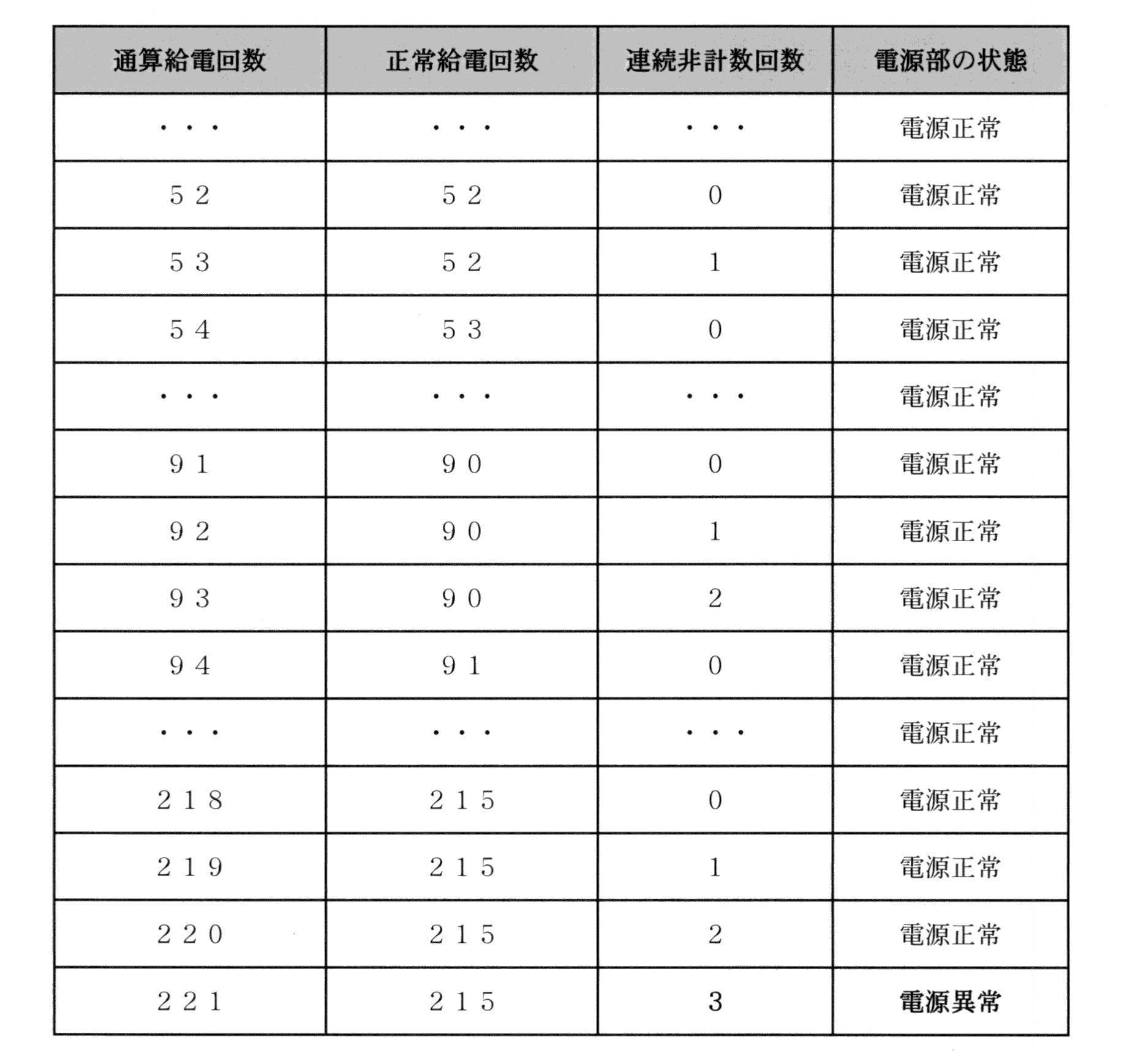
An example of the relationship between the total number of power supplies and the number of normal power supplies is shown in Table 3 below, following Tables 1 and 2 described above.
上記表3の例では、閾値回数が「3」回にセットされていることを想定している。つまり、連続非計数回数が「3」になったときに、はじめて電源部20の状態が「電源異常」であると判定される。より詳細には、通算給電回数が1回から52回までは正常給電回数も同様に計数され、電源部20の状態は「電源正常」と判定される。通算給電回数が53回のときは、正常給電回数は52回であり、計数されなかったことから、連続非計数回数は1回となる。しかしながら、連続非計数回数(1回)は閾値回数である「3」回にまだ達していないので、電源部20の状態は尚も「電源正常」と判定される。そして、通算給電回数が54回のときに正常給電回数が53に計数されたことから、連続非計数回数が再び0回にリセットされる。
In the example of Table 3 above, it is assumed that the threshold number is set to "3" times. That is, when the number of continuous non-counts reaches "3", the state of the power supply unit 20 is determined to be "power supply abnormality" for the first time. More specifically, when the total number of times of power supply is from 1 to 52, the number of times of normal power supply is similarly counted, and the state of the power supply unit 20 is determined to be "normal power supply". When the total number of times of power supply is 53, the number of times of normal power supply is 52 times, and since it was not counted, the number of times of continuous non-counting is one. However, since the number of consecutive non-counts (1 time) has not yet reached the threshold number of "3" times, the state of the power supply unit 20 is still determined to be "normal power supply". Then, since the normal power supply count is counted to 53 when the total power supply count is 54, the continuous non-counting count is reset to 0 again.
通算給電回数が55回から91回までは正常給電状態も計数され、連続非計数回数は0回のままである。次の通算給電回数が92回及び93回のときは、正常給電回数は90回であり計数されなかった。つまり、通算給電回数が93回のとき、連続非計数回数は2回となる。しかしながら、この場合もまた(連続非計数回数は「3」回にまだ達していないので)電源部20の状態は尚も「電源正常」と判定される。通算給電回数が次の94回のときに正常給電回数が91回に計数されたことから、連続非計数回数は再び0回にリセットされる。
From 55 to 91 times of total power supply, the normal power supply state is also counted, and the number of continuous non-counting times remains 0. When the next total number of feedings was 92 and 93, the number of normal feedings was 90 and was not counted. That is, when the total number of times of power supply is 93, the number of continuous non-counting times is 2. However, also in this case, the state of the power supply unit 20 is still determined to be "normal power supply" (since the number of consecutive non-counts has not yet reached "3" times). Since the normal power supply count was counted to 91 when the total power supply count was the next 94 times, the continuous non-counting count is reset to 0 again.
通算給電回数が95回から218回までは正常給電状態も計数され、連続非計数回数は0回のままである。次の通算給電回数が219から221回のときは、正常給電回数は215回であり計数されなかった。つまり、通算給電回数が221回のときは連続非計数回数が3回となり、閾値回数に達したことになる。この時に電源部20の状態が「電源異常」と判定されることになる。
From 95 to 218 total power supply times, the normal power supply state is also counted, and the continuous non-counting number remains 0 times. When the next total number of times of power supply was 219 to 221 times, the number of times of normal power supply was 215 times and was not counted. That is, when the total number of times of power supply is 221 times, the number of consecutive non-counts is 3 times, which means that the threshold number is reached. At this time, the state of the power supply unit 20 is determined to be "power supply abnormality".
前述の表1では通算給電回数が53回のときに「電源異常」と判定され、また前述の表2では通算給電回数が93回のときに「電源異常」と判定されたのに対し、本変形例では通算給電回数が221回のときに「電源異常」と判定されている。つまり、本変形例を適用すれば、センサ70の不具合等に伴うノイズ等をより考慮して電源部20の状態を判定することが実現できる。すなわち、よりいっそう精度よく電源部20の状態を判定することができる。
In Table 1 above, when the total number of power supplies is 53, it is determined as "power supply abnormality", and in Table 2 above, when the total number of power supplies is 93, it is determined as "power supply abnormality". In the modified example, when the total number of times of power supply is 221 times, it is determined as "power supply abnormality". That is, by applying this modification, it is possible to determine the state of the power supply unit 20 in consideration of noise and the like caused by a malfunction of the sensor 70. That is, the state of the power supply unit 20 can be determined more accurately.
(ii)電源部20の給電動作の変更例
上記説明においては、制御部50は、通算給電回数に基づいて、通知部60に電源部20の状態を異なる態様で通知させ(ステップS19)、その後、電源部20の状態が「電源異常」の場合には電源部20の給電動作を禁止する(ステップS23)構成とした。しかしながら、電源部20の給電動作が一律に禁止されるのに替えて、制御部50は、通算給電回数に基づき、異なる態様で電源部20の給電動作を制御するように構成されてもよい。 (Ii) Example of changing the power supply operation of thepower supply unit 20 In the above description, the control unit 50 causes the notification unit 60 to notify the state of the power supply unit 20 in a different manner based on the total number of times of power supply (step S19), and then. When the state of the power supply unit 20 is "power supply abnormality", the power supply operation of the power supply unit 20 is prohibited (step S23). However, instead of uniformly prohibiting the power supply operation of the power supply unit 20, the control unit 50 may be configured to control the power supply operation of the power supply unit 20 in a different manner based on the total number of times of power supply.
上記説明においては、制御部50は、通算給電回数に基づいて、通知部60に電源部20の状態を異なる態様で通知させ(ステップS19)、その後、電源部20の状態が「電源異常」の場合には電源部20の給電動作を禁止する(ステップS23)構成とした。しかしながら、電源部20の給電動作が一律に禁止されるのに替えて、制御部50は、通算給電回数に基づき、異なる態様で電源部20の給電動作を制御するように構成されてもよい。 (Ii) Example of changing the power supply operation of the
例えば、前述の1≦N<100の場合には、制御部50は、電源部20に落下や衝撃に伴うバッテリセルの破損等の重度の高い不具合が発生しているものとみなし、電池が交換されるまで恒久的に電力を供給させないよう電源部20の動作を停止させてもよい。また、10000≦Nの場合には、制御部50は、経年劣化等に伴う電池寿命の問題が発生しているものとみなし、電源部20の動作を敢えて停止させないでもよい。これにより、ユーザに対し安全性及び利便性に更に配慮した吸入装置10を提供することができる。
For example, in the case of 1 ≦ N <100 described above, the control unit 50 considers that the power supply unit 20 has a serious problem such as damage to the battery cell due to dropping or impact, and the battery is replaced. The operation of the power supply unit 20 may be stopped so that the power is not permanently supplied until the power supply is performed. Further, in the case of 10000 ≦ N, the control unit 50 may consider that the problem of battery life due to aging deterioration or the like has occurred, and may not dare to stop the operation of the power supply unit 20. This makes it possible to provide the inhalation device 10 with further consideration for safety and convenience to the user.
(iii)通知部60の通知動作の変更例
上記説明においては、吸引装置10の通知部60における通知動作(ステップS19)は、1又は複数のLEDを用いて異なる色を発光するように構成されるものとした。しかしながら、通知の態様は、これに限定されず、ユーザに対して明示的な通知を行うように動作するものであれば任意のものでよい。具体的には、発光、表示、発声、振動、及びこれらの組み合わせ等によって実現することができる。これにより、ユーザに対する柔軟な通知態様を実現することができる。 (Iii) Example of changing the notification operation of thenotification unit 60 In the above description, the notification operation (step S19) of the notification unit 60 of the suction device 10 is configured to emit different colors by using one or a plurality of LEDs. It was supposed to be. However, the mode of notification is not limited to this, and any mode may be used as long as it operates to give explicit notification to the user. Specifically, it can be realized by light emission, display, vocalization, vibration, and a combination thereof. As a result, a flexible notification mode for the user can be realized.
上記説明においては、吸引装置10の通知部60における通知動作(ステップS19)は、1又は複数のLEDを用いて異なる色を発光するように構成されるものとした。しかしながら、通知の態様は、これに限定されず、ユーザに対して明示的な通知を行うように動作するものであれば任意のものでよい。具体的には、発光、表示、発声、振動、及びこれらの組み合わせ等によって実現することができる。これにより、ユーザに対する柔軟な通知態様を実現することができる。 (Iii) Example of changing the notification operation of the
例えば、通知部60は、1又は複数のバイブレータを含んでもよく、計数された通算給電回数の値の範囲に基づいて1又は複数の振動タイプで振動を発生するように構成されてもよい。別の例では、通知部60は、1又は複数のスピーカを含んでもよく、計数された通算給電回数の値の範囲に基づいて音を発生するように構成されてもよい。他にも、通知部60は、1又は複数のディスプレイを含んでもよく、計数された通算給電回数の値の範囲に基づいてディスプレイ上に表示するように構成されてもよい。また、制御部50は、ディスプレイに表示を行う際には、電源異常情報の少なくとも一部(例えば、前述の異常コード)を併せてディスプレイに表示させてもよい。
For example, the notification unit 60 may include one or more vibrators, and may be configured to generate vibrations of one or more vibration types based on the range of the counted total number of times of feeding. In another example, the notification unit 60 may include one or more speakers and may be configured to generate sound based on a range of counted total feed count values. In addition, the notification unit 60 may include one or more displays, and may be configured to display on the display based on the range of the counted total number of feeds. Further, when displaying on the display, the control unit 50 may also display at least a part of the power supply abnormality information (for example, the above-mentioned abnormality code) on the display.
<第2実施形態>
以下に、第2実施形態に係る吸引装置100について図9を参照して説明する。なお、第1実施形態に関連して既に説明した構成及び機能については略同一符号を付して詳細説明を省略する。本実施形態の吸引装置100では、センサ70(例えば、吸引センサ)がユーザによる一連の所定回数(例えば8回)の吸引動作の開始を検知すると、吸引装置100の電源がオンされると共に、電源部20による給電動作が開始されて、エアロゾルが生成される。この給電動作はセンサ70が一連の吸引動作の終了を検知するまで実施される。 <Second Embodiment>
Thesuction device 100 according to the second embodiment will be described below with reference to FIG. The configurations and functions already described in relation to the first embodiment are designated by substantially the same reference numerals, and detailed description thereof will be omitted. In the suction device 100 of the present embodiment, when the sensor 70 (for example, the suction sensor) detects the start of a series of suction operations by the user (for example, eight times), the suction device 100 is turned on and the power is supplied. The power feeding operation by the unit 20 is started, and the aerosol is generated. This power feeding operation is performed until the sensor 70 detects the end of a series of suction operations.
以下に、第2実施形態に係る吸引装置100について図9を参照して説明する。なお、第1実施形態に関連して既に説明した構成及び機能については略同一符号を付して詳細説明を省略する。本実施形態の吸引装置100では、センサ70(例えば、吸引センサ)がユーザによる一連の所定回数(例えば8回)の吸引動作の開始を検知すると、吸引装置100の電源がオンされると共に、電源部20による給電動作が開始されて、エアロゾルが生成される。この給電動作はセンサ70が一連の吸引動作の終了を検知するまで実施される。 <Second Embodiment>
The
(2-1)吸引装置の構成及び動作
図9は、第2実施形態に係る吸引装置100の構成の概略的なブロック図である。図9に示されるように、本実施形態では、吸引装置100は、第1の部材102、第2の部材104、及び第3の部材126を備え、これらが装着されることにより全体が構成される。具体的には、第1の部材102には第2の部材104が着脱可能にはめ込まれ、第2の部材104には第3の部材126が着脱可能にはめ込まれる。また、本実施形態では、第2の部材104がエアロゾル源を収容した吸引物品であり、第3の部材126が香味源を収容した吸引物品である。 (2-1) Configuration and Operation of Suction Device FIG. 9 is a schematic block diagram of the configuration of thesuction device 100 according to the second embodiment. As shown in FIG. 9, in the present embodiment, the suction device 100 includes a first member 102, a second member 104, and a third member 126, and the entire structure is configured by mounting these members. To. Specifically, the second member 104 is detachably fitted into the first member 102, and the third member 126 is detachably fitted into the second member 104. Further, in the present embodiment, the second member 104 is a suction article containing an aerosol source, and the third member 126 is a suction article containing a flavor source.
図9は、第2実施形態に係る吸引装置100の構成の概略的なブロック図である。図9に示されるように、本実施形態では、吸引装置100は、第1の部材102、第2の部材104、及び第3の部材126を備え、これらが装着されることにより全体が構成される。具体的には、第1の部材102には第2の部材104が着脱可能にはめ込まれ、第2の部材104には第3の部材126が着脱可能にはめ込まれる。また、本実施形態では、第2の部材104がエアロゾル源を収容した吸引物品であり、第3の部材126が香味源を収容した吸引物品である。 (2-1) Configuration and Operation of Suction Device FIG. 9 is a schematic block diagram of the configuration of the
例えば、第1の部材102は、吸引装置100に使用される電源ユニットとしてよく、電源部20、制御部50、通知部60、センサ70、メモリ80、及び接続部(非図示)を備え、電気的に接続される。第2の部材104である(エアロゾル源収容)吸引物品は、カートリッジとしてよく、リザーバ116、霧化部118、空気取込流路120、及びエアロゾル流路121を備える。第3の部材126である(香味源収容)吸引物品は、カプセルとしてよく、香味源保持部128及び吸口部122を備える。吸引装置100が電子たばこである場合、香味源保持部128内には、たばこに含有される香喫味成分が含まれてもよい。
For example, the first member 102 may be a power supply unit used for the suction device 100, and includes a power supply unit 20, a control unit 50, a notification unit 60, a sensor 70, a memory 80, and a connection unit (not shown), and is electric. Is connected. The suction article (accommodating the aerosol source), which is the second member 104, may be a cartridge and includes a reservoir 116, an atomizing section 118, an air intake flow path 120, and an aerosol flow path 121. The suction article (containing the flavor source), which is the third member 126, may be a capsule and includes a flavor source holding portion 128 and a mouthpiece portion 122. When the suction device 100 is an electronic cigarette, the flavor source holding portion 128 may contain a flavor component contained in the cigarette.
(i)電源ユニットの構成
第1の部材102である電源ユニットに関し、電源部20は、ユーザの吸引動作に応じてエアロゾル源を霧化させるために霧化部118への給電動作を実施する(以下、第1実施形態で説明した「加熱部」は、第2実施形態では「霧化部」と称することもある。)。 (I) Configuration of Power Supply Unit With respect to the power supply unit, which is thefirst member 102, the power supply unit 20 performs a power supply operation to the atomization unit 118 in order to atomize the aerosol source in response to the suction operation of the user. Hereinafter, the "heating part" described in the first embodiment may be referred to as an "atomization part" in the second embodiment).
第1の部材102である電源ユニットに関し、電源部20は、ユーザの吸引動作に応じてエアロゾル源を霧化させるために霧化部118への給電動作を実施する(以下、第1実施形態で説明した「加熱部」は、第2実施形態では「霧化部」と称することもある。)。 (I) Configuration of Power Supply Unit With respect to the power supply unit, which is the
第1実施形態と同様、制御部50は、電源部20の給電動作にしたがって計数される通算給電回数及び正常給電回数に基づいて、電源部20の状態を判定する。ここで、正常給電回数は、給電動作を通じて電源部20の電圧値が所定の電圧閾値以上である場合に計数される。このように、通算給電回数及び正常給電回数という2つのパラメータを用いることにより、電源ユニットの制御部50は、電源ユニットの使用時、特に、ユーザによる吸引動作中のバッテリ放電時の電源部の正常又は異常の状態を適切に把握することができる。
Similar to the first embodiment, the control unit 50 determines the state of the power supply unit 20 based on the total number of times of power supply and the number of normal power supplies counted according to the power supply operation of the power supply unit 20. Here, the number of normal power feeds is counted when the voltage value of the power supply unit 20 is equal to or higher than a predetermined voltage threshold value through the power supply operation. In this way, by using the two parameters of the total number of power supplies and the number of normal power supplies, the control unit 50 of the power supply unit is normal in the power supply unit when the power supply unit is used, especially when the battery is discharged during the suction operation by the user. Alternatively, the abnormal state can be appropriately grasped.
また、制御部50は、正常給電回数が計数されずに通算給電回数と正常給電回数とが一致しない場合に、電源部20の状態が「電源異常」であると判定する。そして、制御部50は、電源部20の状態が「電源異常」であると判定される場合に電源異常情報をメモリ80に格納し、電源異常情報の格納に応じて、電源部20による給電動作を禁止する。更に、制御部50は、電源ユニットに接続される外部装置(非図示)からの指示に応じて、メモリ80に格納された電源異常情報をメモリ80から削除し、電源異常情報の削除に応じて、禁止された給電動作を許可する。
Further, the control unit 50 determines that the state of the power supply unit 20 is "power supply abnormality" when the normal power supply count is not counted and the total power supply count and the normal power supply count do not match. Then, the control unit 50 stores the power supply abnormality information in the memory 80 when the state of the power supply unit 20 is determined to be "power supply abnormality", and the power supply operation by the power supply unit 20 according to the storage of the power supply abnormality information. Is prohibited. Further, the control unit 50 deletes the power supply abnormality information stored in the memory 80 from the memory 80 in response to an instruction from an external device (not shown) connected to the power supply unit, and responds to the deletion of the power supply abnormality information. , Allow prohibited power supply operations.
このように、通算給電回数及び正常給電回数という2つのパラメータを用いることにより、バッテリ放電時に不具合が発生したような場合に、電源ユニットの制御部50は、バッテリ放電時の電源部の異常状態を確実に判定することができる。また、電源部20による給電動作を禁止することにより、ユーザへの安全性を高めることができる。更に、電源異常情報を削除について外部装置からの指示を必要とすることにより、ユーザの誤操作による当該吸引操作の誤動作を防止し、ユーザへの安全性を高めることができる。加えて、一旦禁止された給電動作を再び許可することができるようにすることにより、ユーザの利便性を高めることができる。
In this way, by using the two parameters of the total number of power supplies and the number of normal power supplies, when a problem occurs during battery discharge, the control unit 50 of the power supply unit determines the abnormal state of the power supply unit during battery discharge. It can be determined with certainty. Further, by prohibiting the power supply operation by the power supply unit 20, the safety for the user can be enhanced. Further, by requiring an instruction from an external device for deleting the power supply abnormality information, it is possible to prevent the suction operation from malfunctioning due to the user's erroneous operation and enhance the safety to the user. In addition, the convenience of the user can be enhanced by allowing the once prohibited power feeding operation to be permitted again.
通知部60は、ユーザに対して明示的な通知を行うように動作する。具体的には、通知部60は、必要に応じて、発光、表示、発声、振動、及びこれらの組み合わせ等によって、ユーザに対して様々な態様の通知を行う。例えば、通知部60は、1又は複数のLEDを含んでもよく、判定された電源部20の状態に応じて、1又は複数の色で発光するように構成されてもよい。
The notification unit 60 operates so as to give an explicit notification to the user. Specifically, the notification unit 60 notifies the user in various modes by light emission, display, vocalization, vibration, and a combination thereof, as necessary. For example, the notification unit 60 may include one or more LEDs, and may be configured to emit light in one or more colors depending on the determined state of the power supply unit 20.
本実施形態では、通知部60は、電源部20の状態を通知するように構成される。例えば、電源部20が正常状態又は異常状態であるかを通知し、更に、通算給電回数に基づいて、電源部20の状態を異なる態様で通知するように構成されるのがよい。つまり、吸引動作中のユーザは、通知態様を知覚することにより、バッテリ放電時の電源部の正常又は異常の状態を直感的に把握することができる。また、当該電源ユニットの修理に関する利便性を向上させることができる。
In the present embodiment, the notification unit 60 is configured to notify the status of the power supply unit 20. For example, it is preferable to notify whether the power supply unit 20 is in a normal state or an abnormal state, and further notify the state of the power supply unit 20 in different modes based on the total number of times of power supply. That is, the user during the suction operation can intuitively grasp the normal or abnormal state of the power supply unit when the battery is discharged by perceiving the notification mode. In addition, the convenience of repairing the power supply unit can be improved.
センサ70は、種々のセンサから構成される。センサ70は、放電状態(つまり、霧化部118への給電動作)にわたる電源部20の電圧値を検知するように構成される。また、センサ70は、マイクロフォン・コンデンサのような吸引センサを含むように構成され、ユーザによる吸引動作を検知し、特に、ユーザによる一連の吸引動作の開始及び終了を特定するように構成される。
The sensor 70 is composed of various sensors. The sensor 70 is configured to detect the voltage value of the power supply unit 20 over the discharge state (that is, the power feeding operation to the atomization unit 118). The sensor 70 is also configured to include a suction sensor, such as a microphone capacitor, to detect a suction action by the user and, in particular, to identify the start and end of a series of suction actions by the user.
接続部は、第1実施形態と同様に、外部接続端子(22)としてよく、外部装置と接続される際に、外部装置からの命令に基づいて、メモリ80内に格納された吸引装置100の各種設定データ及び/又はファームウェアを書き換え可能となるように構成されるのがよい。
The connection portion may be an external connection terminal (22) as in the first embodiment, and when connected to the external device, the suction device 100 stored in the memory 80 based on a command from the external device. It should be configured so that various setting data and / or firmware can be rewritten.
(ii)カートリッジの構成
第2の部材104((エアロゾル源収容)吸引物品)であるカートリッジに関し、リザーバ116は、エアロゾル源を保持する。例えば、リザーバ116は、繊維状又は多孔質性の素材から構成され、繊維間の隙間や多孔質材料の細孔に液体としてのエアロゾル源を保持する。上記の繊維状又は多孔質性の素材には、例えばコットンやガラス繊維、又はたばこ原料等を用いることができる。リザーバ116は、液体を収容するタンクとして構成されてもよい。リザーバ116は、消費されたエアロゾル源を補充することができる構成を有してもよい。或いは、リザーバ116は、エアロゾル源が消費された際にリザーバ116自体を交換することができるように構成されてもよい。また、エアロゾル源は液体に限られるものではなく、固体でもよい。エアロゾル源が固体である場合のリザーバ116は、例えば繊維状又は多孔質性の素材を用いない空洞の容器であってもよい。 (Ii) Structure of Cartridge With respect to the cartridge which is the second member 104 ((aerosol source containing) suction article), thereservoir 116 holds the aerosol source. For example, the reservoir 116 is composed of a fibrous or porous material and holds an aerosol source as a liquid in the gaps between the fibers and in the pores of the porous material. For the above fibrous or porous material, for example, cotton, glass fiber, tobacco raw material, or the like can be used. The reservoir 116 may be configured as a tank for containing the liquid. The reservoir 116 may have a configuration capable of replenishing the consumed aerosol source. Alternatively, the reservoir 116 may be configured so that the reservoir 116 itself can be replaced when the aerosol source is consumed. Further, the aerosol source is not limited to a liquid, but may be a solid. When the aerosol source is a solid, the reservoir 116 may be, for example, a hollow container without a fibrous or porous material.
第2の部材104((エアロゾル源収容)吸引物品)であるカートリッジに関し、リザーバ116は、エアロゾル源を保持する。例えば、リザーバ116は、繊維状又は多孔質性の素材から構成され、繊維間の隙間や多孔質材料の細孔に液体としてのエアロゾル源を保持する。上記の繊維状又は多孔質性の素材には、例えばコットンやガラス繊維、又はたばこ原料等を用いることができる。リザーバ116は、液体を収容するタンクとして構成されてもよい。リザーバ116は、消費されたエアロゾル源を補充することができる構成を有してもよい。或いは、リザーバ116は、エアロゾル源が消費された際にリザーバ116自体を交換することができるように構成されてもよい。また、エアロゾル源は液体に限られるものではなく、固体でもよい。エアロゾル源が固体である場合のリザーバ116は、例えば繊維状又は多孔質性の素材を用いない空洞の容器であってもよい。 (Ii) Structure of Cartridge With respect to the cartridge which is the second member 104 ((aerosol source containing) suction article), the
霧化部118は、エアロゾル源からエアロゾルを生成するように構成される。具体的には、霧化部118は、エアロゾル源を霧化又は気化することにより、エアロゾルを生成する。吸引装置100がネブライザ等の医療用吸入器である場合には、霧化部118は、薬剤を含んだエアロゾル源を霧化又は気化することにより、エアロゾルを生成する。センサ70によって吸引動作が検出されると、霧化部118は、電源部20からの電力の供給を受けてエアロゾルを生成する。例えば、ウィック(図示せず)が、リザーバ116と霧化部118とを連結するように設けられてもよい。この場合、ウィックの一部はリザーバ116の内部に通じてエアロゾル源と接触する。ウィックの他の一部は霧化部118へ延びる。エアロゾル源は、ウィックの毛細管効果によってリザーバ116から霧化部118へと運ばれる。例えば、霧化部118は、電源部20に電気的に接続されたヒータを備える。ヒータは、ウィックと接触又は近接するように配置される。吸引動作が検出されると、制御部50は、霧化部118のヒータを制御し、ウィックを通じて運ばれたエアロゾル源を加熱することによって当該エアロゾル源を霧化する。霧化部118の別の例は、エアロゾル源を超音波振動によって霧化する超音波式霧化器であってもよい。
The atomizing unit 118 is configured to generate an aerosol from an aerosol source. Specifically, the atomizing unit 118 produces an aerosol by atomizing or vaporizing the aerosol source. When the suction device 100 is a medical inhaler such as a nebulizer, the atomizing unit 118 produces an aerosol by atomizing or vaporizing an aerosol source containing a drug. When the suction operation is detected by the sensor 70, the atomizing unit 118 receives the electric power supplied from the power supply unit 20 to generate an aerosol. For example, a wick (not shown) may be provided to connect the reservoir 116 and the atomizing section 118. In this case, a portion of the wick passes through the interior of the reservoir 116 and contacts the aerosol source. The other part of the wick extends to the atomization section 118. The aerosol source is carried from the reservoir 116 to the atomizer 118 by the wick's capillary effect. For example, the atomizing unit 118 includes a heater electrically connected to the power supply unit 20. The heater is placed in contact with or in close proximity to the wick. When the suction operation is detected, the control unit 50 controls the heater of the atomizing unit 118 and atomizes the aerosol source by heating the aerosol source carried through the wick. Another example of the atomizing unit 118 may be an ultrasonic atomizer that atomizes an aerosol source by ultrasonic vibration.
第2の部材104であるカートリッジには、リザーバ116の内部に空気を流入するために、空気を流入させるための通気口が形成される。そして、通気口から連結された空気取込流路120が霧化部118に接続され、空気取込流路120は吸引装置100の外部へ通じている。霧化部118において生成されたエアロゾルは、空気取込流路120を介して取り込まれた空気と混合される。エアロゾルと空気の混合流体は、矢印124で示されるように、エアロゾル流路121へと送り出される。エアロゾル流路121は、第2の部材104及び第3の部材126にわたって延在し、霧化部118において生成されたエアロゾルと空気との混合流体を第3の部材126の吸口部122まで輸送するための管状構造を有する。
The cartridge, which is the second member 104, is formed with a vent for allowing air to flow into the reservoir 116. Then, the air intake flow path 120 connected from the vent is connected to the atomizing unit 118, and the air intake flow path 120 leads to the outside of the suction device 100. The aerosol produced in the atomizing section 118 is mixed with the air taken in through the air intake flow path 120. The mixed fluid of aerosol and air is pumped into the aerosol flow path 121, as indicated by arrow 124. The aerosol flow path 121 extends over the second member 104 and the third member 126, and transports the mixed fluid of aerosol and air generated in the atomizing portion 118 to the mouthpiece 122 of the third member 126. Has a tubular structure for.
(iii)カプセルの構成
第3の部材126((香味源収容)吸引物品)であるカプセルに関し、香味源保持部128は、エアロゾルに香味を付与するためのコンポーネントである。香味源保持部128は、エアロゾル流路121の途中に配置される。霧化部118によって生成されたエアロゾルと空気との混合流体(以下、混合流体を単にエアロゾルと称することもある。)は、エアロゾル流路121を通って吸口部122まで流れる。このように、香味源保持部128は、エアロゾルの流れに関して霧化部118よりも下流に設けられている。換言すれば、霧化部118よりも香味源保持部128の方が、エアロゾル流路121の中で吸口部122に近い側に位置する。したがって、霧化部118によって生成されたエアロゾルは、香味源保持部128を通過してから吸口部122へ達する。エアロゾルが香味源保持部128を通過する際、香味源保持部128に含まれる香喫味成分がエアロゾルに付与される。 (Iii) Capsule Structure With respect to the capsule which is the third member 126 ((flavor source containing) suction article), the flavorsource holding portion 128 is a component for imparting flavor to the aerosol. The flavor source holding portion 128 is arranged in the middle of the aerosol flow path 121. The mixed fluid of aerosol and air generated by the atomizing unit 118 (hereinafter, the mixed fluid may be simply referred to as aerosol) flows through the aerosol flow path 121 to the mouthpiece 122. As described above, the flavor source holding portion 128 is provided downstream of the atomizing portion 118 with respect to the flow of the aerosol. In other words, the flavor source holding portion 128 is located closer to the mouthpiece 122 in the aerosol flow path 121 than the atomizing portion 118. Therefore, the aerosol produced by the atomizing unit 118 passes through the flavor source holding unit 128 and then reaches the mouthpiece 122. When the aerosol passes through the flavor source holding portion 128, the flavor component contained in the flavor source holding portion 128 is imparted to the aerosol.
第3の部材126((香味源収容)吸引物品)であるカプセルに関し、香味源保持部128は、エアロゾルに香味を付与するためのコンポーネントである。香味源保持部128は、エアロゾル流路121の途中に配置される。霧化部118によって生成されたエアロゾルと空気との混合流体(以下、混合流体を単にエアロゾルと称することもある。)は、エアロゾル流路121を通って吸口部122まで流れる。このように、香味源保持部128は、エアロゾルの流れに関して霧化部118よりも下流に設けられている。換言すれば、霧化部118よりも香味源保持部128の方が、エアロゾル流路121の中で吸口部122に近い側に位置する。したがって、霧化部118によって生成されたエアロゾルは、香味源保持部128を通過してから吸口部122へ達する。エアロゾルが香味源保持部128を通過する際、香味源保持部128に含まれる香喫味成分がエアロゾルに付与される。 (Iii) Capsule Structure With respect to the capsule which is the third member 126 ((flavor source containing) suction article), the flavor
例えば、吸引装置100が電子たばこである場合、香味源保持部128は、刻みたばこ又はたばこ原料を粒状、シート状もしくは粉末状に成形した加工物等、たばこ由来のものであってもよい。香味源保持部128はまた、たばこ以外の植物(例えばミントやハーブ等)から作られた非たばこ由来のものであってもよい。例えば、香味源保持部128は、ニコチン成分を含む。香味源保持部128は、メントール等の香料成分を含有してもよい。香味源保持部128に加えて、リザーバ116も香喫味成分を含んだ物質を有してもよい。例えば、吸引装置100は、香味源保持部128にたばこ由来の香味物質を保持し、リザーバ116には非たばこ由来の香味物質を含むように構成されてもよい。
For example, when the suction device 100 is an electronic cigarette, the flavor source holding unit 128 may be derived from tobacco, such as a processed product obtained by molding chopped tobacco or a tobacco raw material into a granular, sheet-like or powder-like form. The flavor source holder 128 may also be of non-tobacco origin made from plants other than tobacco (eg, mint, herbs, etc.). For example, the flavor source holding portion 128 contains a nicotine component. The flavor source holding portion 128 may contain a fragrance component such as menthol. In addition to the flavor source holding portion 128, the reservoir 116 may also have a substance containing a flavor component. For example, the suction device 100 may be configured to hold a tobacco-derived flavoring substance in the flavor source holding portion 128 and to include a non-tobacco-derived flavoring substance in the reservoir 116.
(2-2)電源ユニットの動作の変更例
上記説明においては、制御部50は、通算給電回数及び正常給電回数の各値が一致するかに基づき、これらが一致しない場合は、電源部20の状態が「電源異常」と判定される構成とした。ここでは、正常給電回数は、給電動作中に電源部20の電圧値が所定の電源閾値未満となった場合には計数されない構成とした。 (2-2) Example of changing the operation of the power supply unit In the above description, thecontrol unit 50 is based on whether the values of the total number of power supplies and the number of normal power supplies match, and if they do not match, the power supply unit 20 The configuration is such that the state is determined to be "power supply error". Here, the normal power supply frequency is not counted when the voltage value of the power supply unit 20 becomes less than a predetermined power supply threshold value during the power supply operation.
上記説明においては、制御部50は、通算給電回数及び正常給電回数の各値が一致するかに基づき、これらが一致しない場合は、電源部20の状態が「電源異常」と判定される構成とした。ここでは、正常給電回数は、給電動作中に電源部20の電圧値が所定の電源閾値未満となった場合には計数されない構成とした。 (2-2) Example of changing the operation of the power supply unit In the above description, the
しかしながら、センサ70が電源部20の電圧値を検知する際には、センサ70の不具合などによりノイズが発生して誤検知することも想定される。そこで、制御部50は、通算給電回数及び正常給電回数の各値が単に一致するかのみを判断するのに替えて、第1実施形態において示された図7及び図8の各変更例に示されるフロー図と同様に、電源部20の状態を判定するように構成されてもよい。
However, when the sensor 70 detects the voltage value of the power supply unit 20, it is assumed that noise is generated due to a malfunction of the sensor 70 or the like, resulting in erroneous detection. Therefore, the control unit 50 shows in each of the modified examples of FIGS. 7 and 8 shown in the first embodiment, instead of simply determining whether the values of the total number of times of power supply and the number of times of normal power supply match. The state of the power supply unit 20 may be determined in the same manner as in the flow chart.
例えば、図7に示されたのと同様の変更例では、制御部50は、通算通電回数と正常給電回数の差(非計数回数)が所定の閾値回数に達したかについて判定する。つまり、電源部20の電圧Vbattが電圧閾値未満となったことにより、正常給電回数が複数回数にわたり計数されずに、非計数回数が所定の閾値回数に達した場合に、電源部20の状態が「電源異常」と判定される。
For example, in the same modification as shown in FIG. 7, the control unit 50 determines whether the difference between the total number of times of energization and the number of times of normal power supply (non-counting number) has reached a predetermined threshold number. That is, when the voltage V batt of the power supply unit 20 becomes less than the voltage threshold value, the normal power supply number is not counted over a plurality of times, and the non-counting number reaches a predetermined threshold number, the state of the power supply unit 20 Is determined to be "power supply error".
また、図8に示されたのと同様の変更例では、制御部50は、通算給電回数と正常給電回数とを関連付けてメモリ80に格納する。そして、制御部50は、正常給電回数が連続して複数回数にわたり計数されずに通算給電回数と正常給電回数の差(連続非計数回数)が所定の閾値回数に達したかについて判定する。つまり、電源部20の電圧Vbattが電圧閾値未満となることにより、正常給電回数が連続して複数回数にわたり計数されずに、連続非計数回数が所定の閾値回数に達した場合に、電源部20の状態が「電源異常」と判定される。
Further, in the same modification as shown in FIG. 8, the control unit 50 stores the total number of times of power supply and the number of times of normal power supply in association with each other in the memory 80. Then, the control unit 50 determines whether the difference between the total number of feeds and the number of normal feeds (continuous non-counting number) reaches a predetermined threshold number without counting the number of normal feeds continuously over a plurality of times. That is, when the voltage V batt of the power supply unit 20 becomes less than the voltage threshold value, the normal power supply count is not continuously counted over a plurality of times, and the continuous non-counting count reaches a predetermined threshold value. The state of 20 is determined to be "power supply abnormality".
ここで、正常給電回数が「連続」して計測されないとは、電源部20の電圧Vbattが電圧閾値未満となるような事象が、或る一の給電動作中と、その次の一の給電動作中との間で連続して発生することに相当する。なお、ここでの一の給電動作とは、ユーザが一連の吸引動作を実施することにより、当該一連の吸引動作の開始から終了までの期間にわたって電源部20から加熱部40に電力を供給する動作のことである。
Here, the fact that the normal power supply count is not measured "continuously" means that the event that the voltage V batt of the power supply unit 20 becomes less than the voltage threshold value occurs during one power supply operation and the next one power supply. It corresponds to the continuous occurrence during operation. The power supply operation here is an operation in which the user performs a series of suction operations to supply electric power from the power supply unit 20 to the heating unit 40 over a period from the start to the end of the series of suction operations. That is.
このような図7及び図8の各変更例に示されたのと同様の変更例によれば、電源ユニットの制御部50は、バッテリ放電時の電源部の異常状態を更に精度よく判定することができる。
According to the same modification as shown in each of the modification of FIGS. 7 and 8, the control unit 50 of the power supply unit determines more accurately the abnormal state of the power supply unit when the battery is discharged. Can be done.
<他の実施形態>
前述の説明において、幾らかの実施形態に係る吸引装置、電源ユニット、及び方法が図面を参照して説明された。本開示は、プロセッサにより実行されると、当該プロセッサに、吸引装置を動作させる方法を実行させるプログラム、又は当該プログラムを格納したコンピュータ読み取り可能な記憶媒体としても実施され得ることが理解される。 <Other embodiments>
In the above description, suction devices, power supply units, and methods according to some embodiments have been described with reference to the drawings. It is understood that the present disclosure, when executed by a processor, can also be implemented as a program that causes the processor to execute a method of operating a suction device, or as a computer-readable storage medium containing the program.
以上、本開示の実施形態が、その変更例及び適用態様と共に説明されたが、これらは例示にすぎず、本開示の範囲を限定するものではないことが理解されるべきである。本開示の趣旨及び範囲から逸脱することなく、実施形態の変更、追加、改良等を適宜行うことができることが理解されるべきである。本開示の範囲は、上述した実施形態のいずれによっても限定されるべきではなく、特許請求の範囲及びその均等物によってのみ規定されるべきである。
Although the embodiments of the present disclosure have been described above together with examples of modifications and applications thereof, it should be understood that these are merely examples and do not limit the scope of the present disclosure. It should be understood that the embodiments can be changed, added, improved, etc. as appropriate without departing from the spirit and scope of the present disclosure. The scope of the present disclosure should not be limited by any of the embodiments described above, but should be defined only by the claims and their equivalents.
10,100…吸引装置、11(11A,11B)…ハウジング、12…カバー、12a…開口、13…電源ボタン、14…蓋部、15…吸引物品(エアロゾル生成基材)、22…外部接続端子、40…加熱部、45…保持部、50…制御部、60…通知部、70…センサ、80…メモリ、102…第1の部材(電源ユニット)、104…第2の部材(カートリッジ/エアロゾル源収容吸引物品)、126…第3の部材(カプセル/香味源収容吸引物品))、116…リザーバ、118…霧化部(加熱部)、120…空気取込流路、121…エアロゾル流路、122…吸口部、128…香味源保持部
10,100 ... Suction device, 11 (11A, 11B) ... Housing, 12 ... Cover, 12a ... Opening, 13 ... Power button, 14 ... Lid, 15 ... Suction article (aerosol generation base material), 22 ... External connection terminal , 40 ... heating unit, 45 ... holding unit, 50 ... control unit, 60 ... notification unit, 70 ... sensor, 80 ... memory, 102 ... first member (power supply unit), 104 ... second member (cartridge / aerosol) Source accommodating suction article), 126 ... Third member (capsule / flavor source accommodating suction article)), 116 ... Reservoir, 118 ... Atomizing part (heating part), 120 ... Air intake flow path, 121 ... Aerosol flow path , 122 ... Mouthpiece, 128 ... Flavor source holder
Claims (20)
- エアロゾル源を霧化する加熱部と、
前記加熱部への給電動作を実施する電源部と、
前記電源部の電圧値を検知するセンサと、
前記給電動作にしたがって計数される通算給電回数及び正常給電回数に基づいて、前記電源部の状態を判定する制御部であって、前記正常給電回数は、前記給電動作を通じて前記電源部の電圧値が所定の電圧閾値以上である場合に計数される、制御部と、
前記電源部の状態を通知する通知部と、
を備える、エアロゾルを生成する吸引装置。 A heating unit that atomizes the aerosol source,
A power supply unit that performs a power supply operation to the heating unit and
A sensor that detects the voltage value of the power supply unit and
It is a control unit that determines the state of the power supply unit based on the total number of power supplys and the number of normal power supplys counted according to the power supply operation, and the normal power supply number is determined by the voltage value of the power supply unit through the power supply operation. A control unit that counts when the voltage is equal to or higher than a predetermined voltage threshold.
A notification unit that notifies the status of the power supply unit and
A suction device that produces an aerosol. - 請求項1記載の吸引装置において、前記通知部が、前記通算給電回数に基づいて、前記電源部の状態を異なる態様で通知する、吸引装置。 The suction device according to claim 1, wherein the notification unit notifies the state of the power supply unit in a different manner based on the total number of times of power supply.
- 請求項1又は2記載の吸引装置において、前記制御部は、前記正常給電回数が計数されずに前記通算給電回数と前記正常給電回数とが一致しない場合に、前記電源部の状態が電源異常であると判定する、吸引装置。 In the suction device according to claim 1 or 2, when the normal power supply count is not counted and the total power supply count and the normal power supply count do not match, the state of the power supply unit is abnormal. A suction device that determines that there is.
- 請求項1から3の何れか一項記載の吸引装置において、前記制御部は、複数回数にわたり前記正常給電回数が計数されずに前記通算給電回数と前記正常給電回数との差が所定の閾値回数に達する場合に、前記電源部の状態が電源異常であると判定する、吸引装置。 In the suction device according to any one of claims 1 to 3, the control unit does not count the number of normal feedings over a plurality of times, and the difference between the total number of feedings and the number of normal feedings is a predetermined threshold number. A suction device that determines that the state of the power supply unit is abnormal.
- 請求項1から4の何れか一項記載の吸引装置において、
前記通算給電回数と前記正常給電回数とが関連付けられており、
前記制御部は、前記正常給電回数が連続して複数回数にわたり計数されずに前記通算給電回数と前記正常給電回数との差が所定の閾値回数に達する場合に、前記電源部の状態が電源異常であると判定する、吸引装置。 In the suction device according to any one of claims 1 to 4.
The total number of times of power supply and the number of times of normal power supply are associated with each other.
When the difference between the total number of times of power supply and the number of times of normal power supply reaches a predetermined threshold number without counting the number of times of normal power supply continuously over a plurality of times, the control unit causes the state of the power supply unit to be abnormal. A suction device that determines that. - 請求項1から5の何れか一項記載の吸引装置において、前記制御部は、
前記電源部の状態が電源異常であると判定される場合に電源異常情報をメモリに格納し、前記電源異常情報の格納に応じて、前記電源部による前記給電動作を禁止する、吸引装置。 In the suction device according to any one of claims 1 to 5, the control unit is
A suction device that stores power supply abnormality information in a memory when it is determined that the state of the power supply unit is abnormal, and prohibits the power supply operation by the power supply unit in response to the storage of the power supply abnormality information. - 請求項6記載の吸引装置において、前記制御部は、更に、前記メモリに格納された前記電源異常情報を削除し、前記電源異常情報の削除に応じて、前記禁止された前記給電動作を許可する、吸引装置。 In the suction device according to claim 6, the control unit further deletes the power supply abnormality information stored in the memory, and permits the prohibited power supply operation in response to the deletion of the power supply abnormality information. , Suction device.
- 請求項7記載の吸引装置において、前記制御部は、当該吸引装置に接続された外部装置からの指示に応じて、前記電源異常情報を削除する、吸引装置。 In the suction device according to claim 7, the control unit deletes the power supply abnormality information in response to an instruction from an external device connected to the suction device.
- 請求項1から8の何れか一項記載の吸引装置において、前記電源部による前記給電動作が、ユーザの電源スイッチの押下に応じて開始され、所定の時間にわたり実施される、吸引装置。 The suction device according to any one of claims 1 to 8, wherein the power supply operation by the power supply unit is started in response to a user's pressing of a power switch and is carried out for a predetermined time.
- エアロゾル源を霧化する加熱部と、
前記加熱部への給電動作を実施する電源部と、
前記電源部の電圧値を検知するセンサと、
前記給電動作にしたがって計数される通算給電回数及び正常給電回数に基づいて、前記電源部の状態を判定する制御部であって、前記正常給電回数は、前記給電動作を通じて前記電源部の電圧値が所定の電圧閾値以上である場合に計数される、制御部と、
前記電源部の状態を通知する通知部と、
を備える、エアロゾルを生成する吸引装置に使用される電源ユニット。 A heating unit that atomizes the aerosol source,
A power supply unit that performs a power supply operation to the heating unit and
A sensor that detects the voltage value of the power supply unit and
It is a control unit that determines the state of the power supply unit based on the total number of power supplys and the number of normal power supplys counted according to the power supply operation, and the normal power supply number is determined by the voltage value of the power supply unit through the power supply operation. A control unit that counts when the voltage is equal to or higher than a predetermined voltage threshold.
A notification unit that notifies the status of the power supply unit and
A power supply unit used in an aerosol-producing suction device. - 請求項10記載の電源ユニットにおいて、前記通知部が、前記通算給電回数に基づいて、前記電源部の状態を異なる態様で通知する、電源ユニット。 The power supply unit according to claim 10, wherein the notification unit notifies the state of the power supply unit in a different manner based on the total number of times of power supply.
- 請求項10又は11記載の電源ユニットにおいて、前記制御部は、前記正常給電回数が計数されずに前記通算給電回数と前記正常給電回数とが一致しない場合に、前記電源部の状態が電源異常であると判定する、電源ユニット。 In the power supply unit according to claim 10 or 11, when the normal power supply count is not counted and the total power supply count and the normal power supply count do not match, the state of the power supply unit is abnormal. A power supply unit that determines that it exists.
- 請求項10から12の何れか一項記載の電源ユニットにおいて、前記制御部は、複数回数にわたり前記正常給電回数が計数されずに前記通算給電回数と前記正常給電回数との差が所定の閾値回数に達する場合に、前記電源部の状態が電源異常であると判定する、電源ユニット。 In the power supply unit according to any one of claims 10 to 12, the control unit does not count the normal power supply count over a plurality of times, and the difference between the total power supply count and the normal power supply count is a predetermined threshold number. A power supply unit that determines that the state of the power supply unit is abnormal.
- 請求項10から13の何れか一項記載の電源ユニットにおいて、
前記通算給電回数と前記正常給電回数とが関連付けられており、
前記制御部は、前記正常給電回数が連続して複数回数にわたり計数されずに前記通算給電回数と前記正常給電回数の差が所定の閾値回数に達する場合に、前記電源部の状態が電源異常であると判定する、電源ユニット。 In the power supply unit according to any one of claims 10 to 13.
The total number of times of power supply and the number of times of normal power supply are associated with each other.
When the difference between the total number of times of power supply and the number of times of normal power supply reaches a predetermined threshold number without counting the number of times of normal power supply continuously over a plurality of times, the control unit causes the state of the power supply unit to be abnormal. A power supply unit that determines that it exists. - 請求項10から14の何れか一項記載の電源ユニットであって、前記制御部は、
前記電源部の状態が電源異常であると判定される場合に電源異常情報をメモリに格納し、前記電源異常情報の格納に応じて、前記電源部による前記給電動作を禁止する、電源ユニット。 The power supply unit according to any one of claims 10 to 14, wherein the control unit is
A power supply unit that stores power supply abnormality information in a memory when it is determined that the state of the power supply unit is abnormal, and prohibits the power supply operation by the power supply unit in response to the storage of the power supply abnormality information. - 請求項15記載の電源ユニットにおいて、前記制御部は、更に、当該電源ユニットに接続された外部装置からの指示に応じて、前記メモリに格納された前記電源異常情報を削除し、前記電源異常情報の削除に応じて、前記禁止された前記給電動作を許可する、電源ユニット。 In the power supply unit according to claim 15, the control unit further deletes the power supply abnormality information stored in the memory in response to an instruction from an external device connected to the power supply unit, and the power supply abnormality information. A power supply unit that allows the prohibited power supply operation in response to the deletion of.
- 請求項10から16の何れか一項記載の電源ユニットにおいて、
前記センサが吸引センサを含み、
前記電源部による前記給電動作が、前記吸引センサによって検知される、ユーザによる一連の吸引動作の開始に応じて開始され、前記一連の吸引動作の終了まで実施される、電源ユニット。 In the power supply unit according to any one of claims 10 to 16.
The sensor includes a suction sensor
A power supply unit in which the power supply operation by the power supply unit is started in response to the start of a series of suction operations by the user detected by the suction sensor, and is carried out until the end of the series of suction operations. - エアロゾルを生成する吸引装置を動作させる方法であって、
エアロゾル源を霧化する加熱部への給電動作を電源部に実施させるステップと、
前記電源部の電圧値をセンサに検知させるステップと、
前記給電動作にしたがって計数される通算給電回数及び正常給電回数に基づいて、前記電源部の状態を判定するステップであって、前記正常給電回数は、前記給電動作を通じて前記電源部の電圧値が所定の電圧閾値以上である場合に計数される、ステップと、
前記電源部の状態を通知するステップと、
を含む、方法。 A method of operating a suction device that produces aerosols.
A step to make the power supply unit perform a power supply operation to the heating unit that atomizes the aerosol source,
The step of causing the sensor to detect the voltage value of the power supply unit,
It is a step of determining the state of the power supply unit based on the total number of times of power supply and the number of normal power supplies counted according to the power supply operation, and the voltage value of the power supply unit is predetermined in the normal power supply number of times The step and, which are counted when the voltage threshold value of
The step of notifying the state of the power supply unit and
Including methods. - 請求項18記載の方法において、前記通知するステップが、前記通算給電回数に基づいて、前記電源部の状態を異なる態様で通知することを含む、方法。 The method according to claim 18, wherein the notification step includes notifying the state of the power supply unit in a different manner based on the total number of times of power supply.
- 請求項18又は19記載の方法において、前記判定するステップが、前記正常給電回数が計数されずに、前記通算給電回数と前記正常給電回数とが一致しない場合に、前記電源部の状態が電源異常であると判定することを含む、方法。
In the method according to claim 18 or 19, when the determination step does not count the normal power supply count and the total power supply count and the normal power supply count do not match, the state of the power supply unit is abnormal. A method that involves determining that.
Priority Applications (4)
| Application Number | Priority Date | Filing Date | Title |
|---|---|---|---|
| JP2021528083A JP7108790B2 (en) | 2019-06-18 | 2019-06-18 | Suction device, power supply unit, and method |
| EP19933510.0A EP3987956A4 (en) | 2019-06-18 | 2019-06-18 | Inhalation device, power supply unit, and method |
| PCT/JP2019/023995 WO2020255233A1 (en) | 2019-06-18 | 2019-06-18 | Inhalation device, power supply unit, and method |
| US17/530,001 US20220071300A1 (en) | 2019-06-18 | 2021-11-18 | Inhalation device, power supply unit, and method |
Applications Claiming Priority (1)
| Application Number | Priority Date | Filing Date | Title |
|---|---|---|---|
| PCT/JP2019/023995 WO2020255233A1 (en) | 2019-06-18 | 2019-06-18 | Inhalation device, power supply unit, and method |
Related Child Applications (1)
| Application Number | Title | Priority Date | Filing Date |
|---|---|---|---|
| US17/530,001 Continuation US20220071300A1 (en) | 2019-06-18 | 2021-11-18 | Inhalation device, power supply unit, and method |
Publications (1)
| Publication Number | Publication Date |
|---|---|
| WO2020255233A1 true WO2020255233A1 (en) | 2020-12-24 |
Family
ID=74036995
Family Applications (1)
| Application Number | Title | Priority Date | Filing Date |
|---|---|---|---|
| PCT/JP2019/023995 WO2020255233A1 (en) | 2019-06-18 | 2019-06-18 | Inhalation device, power supply unit, and method |
Country Status (4)
| Country | Link |
|---|---|
| US (1) | US20220071300A1 (en) |
| EP (1) | EP3987956A4 (en) |
| JP (1) | JP7108790B2 (en) |
| WO (1) | WO2020255233A1 (en) |
Cited By (2)
| Publication number | Priority date | Publication date | Assignee | Title |
|---|---|---|---|---|
| WO2022239065A1 (en) * | 2021-05-10 | 2022-11-17 | 日本たばこ産業株式会社 | Power supply unit for aerosol generation device, and method therefor |
| WO2022239474A1 (en) * | 2021-05-10 | 2022-11-17 | 日本たばこ産業株式会社 | Power supply unit for aerosol generation device |
Families Citing this family (3)
| Publication number | Priority date | Publication date | Assignee | Title |
|---|---|---|---|---|
| WO2024053998A1 (en) * | 2022-09-05 | 2024-03-14 | Kt&G Corporation | Aerosol generating device and operating method thereof |
| WO2024053999A1 (en) * | 2022-09-05 | 2024-03-14 | Kt&G Corporation | Aerosol generating device and method of controlling power supply |
| EP4358772A1 (en) * | 2022-09-05 | 2024-05-01 | KT & G Corporation | Aerosol generating device and control method thereof |
Citations (5)
| Publication number | Priority date | Publication date | Assignee | Title |
|---|---|---|---|---|
| JP2003009405A (en) * | 2001-06-22 | 2003-01-10 | Osaka Gas Co Ltd | Power unit |
| JP2017514463A (en) | 2014-04-30 | 2017-06-08 | フィリップ・モーリス・プロダクツ・ソシエテ・アノニム | Aerosol generator with battery display |
| JP3216735U (en) * | 2018-03-20 | 2018-06-21 | スリー・アールシステム株式会社 | Battery for electronic cigarette and electronic cigarette |
| WO2018138751A1 (en) * | 2017-01-24 | 2018-08-02 | 日本たばこ産業株式会社 | Inhalation device and method and program for operating same |
| WO2019077712A1 (en) * | 2017-10-18 | 2019-04-25 | 日本たばこ産業株式会社 | Battery unit, flavor inhaler, method for controlling battery unit, and program |
Family Cites Families (2)
| Publication number | Priority date | Publication date | Assignee | Title |
|---|---|---|---|---|
| CA3054492C (en) * | 2017-03-06 | 2022-11-29 | Japan Tobacco Inc. | Battery unit, flavor inhaler, method of controlling battery unit, and program |
| PL3698656T3 (en) * | 2017-10-18 | 2024-02-05 | Japan Tobacco Inc. | Inhalation component generation device |
-
2019
- 2019-06-18 EP EP19933510.0A patent/EP3987956A4/en not_active Withdrawn
- 2019-06-18 WO PCT/JP2019/023995 patent/WO2020255233A1/en unknown
- 2019-06-18 JP JP2021528083A patent/JP7108790B2/en active Active
-
2021
- 2021-11-18 US US17/530,001 patent/US20220071300A1/en active Pending
Patent Citations (5)
| Publication number | Priority date | Publication date | Assignee | Title |
|---|---|---|---|---|
| JP2003009405A (en) * | 2001-06-22 | 2003-01-10 | Osaka Gas Co Ltd | Power unit |
| JP2017514463A (en) | 2014-04-30 | 2017-06-08 | フィリップ・モーリス・プロダクツ・ソシエテ・アノニム | Aerosol generator with battery display |
| WO2018138751A1 (en) * | 2017-01-24 | 2018-08-02 | 日本たばこ産業株式会社 | Inhalation device and method and program for operating same |
| WO2019077712A1 (en) * | 2017-10-18 | 2019-04-25 | 日本たばこ産業株式会社 | Battery unit, flavor inhaler, method for controlling battery unit, and program |
| JP3216735U (en) * | 2018-03-20 | 2018-06-21 | スリー・アールシステム株式会社 | Battery for electronic cigarette and electronic cigarette |
Cited By (2)
| Publication number | Priority date | Publication date | Assignee | Title |
|---|---|---|---|---|
| WO2022239065A1 (en) * | 2021-05-10 | 2022-11-17 | 日本たばこ産業株式会社 | Power supply unit for aerosol generation device, and method therefor |
| WO2022239474A1 (en) * | 2021-05-10 | 2022-11-17 | 日本たばこ産業株式会社 | Power supply unit for aerosol generation device |
Also Published As
| Publication number | Publication date |
|---|---|
| EP3987956A1 (en) | 2022-04-27 |
| EP3987956A4 (en) | 2023-01-11 |
| JPWO2020255233A1 (en) | 2021-11-25 |
| US20220071300A1 (en) | 2022-03-10 |
| JP7108790B2 (en) | 2022-07-28 |
Similar Documents
| Publication | Publication Date | Title |
|---|---|---|
| WO2020255233A1 (en) | Inhalation device, power supply unit, and method | |
| JP6949870B2 (en) | Detachable power supply for aerosol delivery equipment | |
| CN108882750B (en) | Suction device, method of operating suction device, and recording medium | |
| EP3116335B1 (en) | An aerosol delivery system and related method, apparatus for providing control information to an aerosol delivery device via a cartridge | |
| KR20200122391A (en) | Control device for electronic aerosol delivery system | |
| CN113786010A (en) | Evaporator with a heat exchanger | |
| KR20190138686A (en) | Refillable Aerosol Delivery Device and Related Methods | |
| WO2020208903A1 (en) | Power supply unit provided to inhalation device, inhalation device, and method for operating power supply unit | |
| JP7158557B2 (en) | FLAVOR COMPONENT GENERATION CONTROL DEVICE, FLAVOR COMPONENT GENERATION DEVICE, CONTROL METHOD AND PROGRAM | |
| JP2022524805A (en) | Electronic aerosol supply system | |
| JP7248810B2 (en) | Battery unit, information processing method, and program | |
| US11944743B2 (en) | Vapor provision systems | |
| JP7239091B2 (en) | Aerosol delivery system | |
| EP3840166A1 (en) | Aerosol delivery device/system | |
| WO2021058776A1 (en) | Smoking substitute device | |
| EP3838025A1 (en) | Aerosol delivery device | |
| EP3714711A1 (en) | Aerosol delivery device | |
| EP3791735A1 (en) | Smoking substitute device | |
| CN113766847A (en) | Smoking substitute system | |
| EP4197375A1 (en) | Aerosol delivery device | |
| EP4197359A1 (en) | Aerosol delivery system | |
| EP3838020A1 (en) | Aerosol delivery device/system | |
| EP4151105A1 (en) | Aerosol delivery device/system | |
| EP3791737A1 (en) | Smoking substitute system | |
| WO2022064174A1 (en) | Aerosol provision system |
Legal Events
| Date | Code | Title | Description |
|---|---|---|---|
| 121 | Ep: the epo has been informed by wipo that ep was designated in this application |
Ref document number: 19933510 Country of ref document: EP Kind code of ref document: A1 |
|
| ENP | Entry into the national phase |
Ref document number: 2021528083 Country of ref document: JP Kind code of ref document: A |
|
| NENP | Non-entry into the national phase |
Ref country code: DE |
|
| ENP | Entry into the national phase |
Ref document number: 2019933510 Country of ref document: EP Effective date: 20220118 |