JP7601331B2 - Rock bolt and its manufacturing method - Google Patents
Rock bolt and its manufacturing method Download PDFInfo
- Publication number
- JP7601331B2 JP7601331B2 JP2021032637A JP2021032637A JP7601331B2 JP 7601331 B2 JP7601331 B2 JP 7601331B2 JP 2021032637 A JP2021032637 A JP 2021032637A JP 2021032637 A JP2021032637 A JP 2021032637A JP 7601331 B2 JP7601331 B2 JP 7601331B2
- Authority
- JP
- Japan
- Prior art keywords
- rock bolt
- head
- pull
- shaft portion
- rock
- Prior art date
- Legal status (The legal status is an assumption and is not a legal conclusion. Google has not performed a legal analysis and makes no representation as to the accuracy of the status listed.)
- Active
Links
Images


Landscapes
- Piles And Underground Anchors (AREA)
- Lining And Supports For Tunnels (AREA)
Description
本発明は、例えばトンネル空間の支保に用いられるロックボルト及びその製造方法に関する。 The present invention relates to rock bolts used, for example, to support tunnel spaces, and to a method for manufacturing the same.
一般的なトンネルでは、図10及び図11に示すように、トンネルの掘削面101に沿って吹付コンクリート102が打設され、吹付コンクリート102から周囲の地山103にロックボルト104が放射状に打設される。各ロックボルト104は、定着材105で地山103に定着されると共に、外挿された支圧プレート106が吹付コンクリート102に密着するように、後端部の雄ねじ107にナット108が嵌められる。そして、放射状に打設されたロックボルト104によってトンネル周囲の地山103に構築されたアーチ構造109により、トンネル空間110が支保される。
In a typical tunnel, as shown in Figures 10 and 11, sprayed
地山103に打設、定着されたロックボルト104は、地山103が押し出してこようとする力Fに対して、ロックボルト104に生ずる引張方向の軸力Tによって抗することにより、アーチ構造109が壊れないように支保する。このようなロックボルト104の機能を発現するには、ロックボルト104が地山103に所要の引抜耐力を有する状態で強固に定着されていることが重要となる。更に、ロックボルト104が破断しないことや、支圧プレート106が吹付コンクリート102に密着するようにロックボルト104にナット締めがされていることも必要となる。
The
また、特許文献1では、ロックボルトの後端部に円形の平鋼板からなるプレート固定部材を一体的に接合し、且つロックボルトの軸部に支圧プレートを外挿するロックボルトが提案されている。このロックボルトは、地山の挿入孔に押し込むように施工され、プレート固定部材で支圧プレートを押さえ付けるようにして地盤に設置される。従って、ロックボルトの施工において支圧プレートをナット締めで取り付ける作業を省略することが可能である。更に、特許文献1のロックボルトは、支圧プレートからトンネル内側に突出するプレート固定部材の厚みが僅かであるため、支圧プレートを覆うように敷設される防水シートの破損を防止できるとされている。
ところで、上述のような地山103に打設されたロックボルト104では、所要の引抜耐力を有する状態で打設されていることを確認するため、施工管理上の仕様に従って引抜試験が行われる。ナット締め方式のロックボルト104に対する引抜試験では、支圧プレート106を押圧するナット108を取り外し、ロックボルト104の後端部の雄ねじ107にカップリングを介してテンションバーを接続し、そのテンションバーをセンターホールラムに挿通して油圧ジャッキで載荷することにより、ロックボルトに引張力をかけ、所定の引抜強度まで抜けてこないかの計測を行う。所定の引抜試験まで抜けてこないことを確認した後には、カップリング、テンションバー、センターホールラム、油圧ジャッキで構成される試験装置をロックボルト104から取り外し、支圧プレート106を押圧するナット108をロックボルト104の雄ねじ107に再度締め付ける。
In the meantime, in order to confirm that the
このような引抜試験は、地山103に打設した全てのロックボルト104からサンプリングした一部のロックボルト104に対して行うのが通常であるが、サンプリングしたロックボルト104に対して行うにしても、ロックボルト104からナット108を取り外し、原状復帰のために再度締め付ける作業にはかなりの手間がかかる。更に、ロックボルト104の後端部の雄ねじ107をトンネル内側に突出する構成では、支圧プレート106を覆うようにトンネル内側に防水シートを敷設する場合、防水シートが破損する危険性が生ずるか、破損を防止する処理を別途に施す必要が生ずる。
This type of pull-out test is usually performed on a sample of all
また、特許文献1のロックボルトは、後端部に支圧プレートを押さえつける平鋼板のプレート固定部材が一体的に接合されているため、引抜試験を行うこと自体が困難である。更に、特許文献1の第2実施形態のように、支圧プレートの角部に地山側に折り曲げた折曲部を形成すると、仮にロックボルトがトンネル内側に飛び出してきた場合に、支圧プレートを覆うように敷設された防水シートに折曲部が引っかかって防水シートが破損する危険性もある。
In addition, the rock bolt in
本発明は上記課題に鑑み提案するものであって、引抜試験を行う際のナットの取り外しと再度の締め付けの作業を無くすことができ、簡単に引抜試験を行うことができると共に、防水シートの破損を防止することができるロックボルト及びその製造方法を提供することを目的とする。 The present invention has been proposed in consideration of the above problems, and aims to provide a lock bolt and a manufacturing method thereof that can eliminate the need to remove and re-tighten the nut when conducting a pull-out test, making it possible to easily conduct a pull-out test and preventing damage to the waterproof sheet.
本発明のロックボルトは、軸部の打設方向における後側に略半球状の頭部が熱間鍛造で前記軸部と一体的に形成され、前記頭部に前記軸部から連続した熱間鍛造による鍛流線が形成され、前記頭部の前端面が前記軸部に外挿される支圧プレートを押圧可能に設けられていると共に、引抜試験用のテンションロッドを螺着可能な雌ねじ部が、前記頭部に後端側から前記軸部と同軸となるように形成されていることを特徴とする。
これによれば、ロックボルトの引抜試験の際には略半球状の頭部の雌ねじ部にテンションロッドを螺着して行うことが可能となり、ナットの取り外しと再度の締め付けの作業を無くすことができ、簡単にロックボルトの引抜試験を行うことができる。また、ナット締めの必要なく、地山に押し込むだけで施工することが可能であるから、ロックボルトの打設作業に要する手間を低減することができる。また、ロックボルトの頭部が略半球状であるため、ロックボルトの頭部を直接若しくは間接的に覆うように敷設される防水シートの破損を防止することができる。
The lock bolt of the present invention is characterized in that a substantially hemispherical head is formed integrally with the shank by hot forging on the rear side of the shank in the pouring direction, a forge flow line is formed in the head by hot forging that is continuous with the shank, the front end surface of the head is arranged so as to be able to press a support plate that is inserted outside the shank, and a female thread portion into which a tension rod for a pull-out test can be screwed is formed in the head from the rear end side so as to be coaxial with the shank.
According to this, when performing a pull-out test on a rock bolt, a tension rod can be screwed into the female thread of the roughly hemispherical head, which eliminates the need to remove and re-tighten the nut, making it easy to perform a pull-out test on the rock bolt. In addition, since the bolt can be installed simply by pushing it into the ground without the need for nut tightening, the labor required for driving the rock bolt can be reduced. In addition, since the head of the rock bolt is roughly hemispherical, damage to the waterproof sheet that is laid to directly or indirectly cover the head of the rock bolt can be prevented.
本発明のロックボルト構造体は、本発明のロックボルトの前記軸部に支圧プレートが外挿され、前記支圧プレートの角部がアール面取りされていることを特徴とする。
これによれば、支圧プレートの角部がアール面取りして形成されることにより、ロックボルトの頭部と支圧プレートを直接若しくは間接的に覆うように敷設される防水シートの破損をより確実に防止することができる。
The rock bolt structure of the present invention is characterized in that a bearing plate is fitted onto the shaft portion of the rock bolt of the present invention, and the corners of the bearing plate are chamfered with a radius.
According to this, by forming the corners of the support plate with a radiused chamfer, damage to the waterproof sheet that is laid to directly or indirectly cover the head of the rock bolt and the support plate can be more reliably prevented.
本発明のロックボルトの製造方法は、本発明のロックボルトを製造する方法であって、前記軸部の外形状と外周サイズを有する棒鋼材の一方の端部に、熱間鍛造で略半球状の前記頭部を形成することを特徴とする。
これによれば、略半球状の頭部を軸部と同一材料から形成することができることに加え、略半球状の頭部に、軸部から連続した熱間鍛造による鍛流線が形成された、内部組織が均質の材料構造、粘りの増した靭性に富む材料構造とすることができる。従って、高強度、高耐力を全長に亘って発揮するロックボルトを得ることができる。また、熱間鍛造の製造により、迅速且つ安価に本発明のロックボルトを製造することができる。
The manufacturing method of the lockbolt of the present invention is a method of manufacturing a lockbolt of the present invention, characterized in that the approximately hemispherical head is formed by hot forging at one end of a steel bar having the outer shape and outer peripheral size of the shaft portion.
This allows the roughly hemispherical head to be made from the same material as the shaft, and also allows the roughly hemispherical head to have a continuous grain flow from hot forging that is continuous with the shaft, resulting in a material structure with a homogenous internal structure and a tougher material structure with increased viscosity. This makes it possible to obtain a rock bolt that exhibits high strength and high yield strength over its entire length. Furthermore, the hot forging process allows the rock bolt of the present invention to be manufactured quickly and inexpensively.
本発明のロックボルトの施工方法は、本発明のロックボルトを施工する方法であって、前記ロックボルトの前記軸部に先端側から支圧プレートを外挿する第1工程と、前記支圧プレートを前記頭部の前端面で地山に押し付けるようにして前記ロックボルトを前記地山に打設する第2工程を備えることを特徴とする。
これによれば、支圧プレートを地山或いは吹付コンクリートに密着させるまでナット締めをする必要が無く、ロックボルトを押し込むように移動するだけでロックボルトを打設することができることから、施工作業を容易化することができる。
The method of installing a rock bolt of the present invention is a method of installing a rock bolt of the present invention, characterized in that it comprises a first step of extrapolating a support plate from the tip side of the shaft portion of the rock bolt, and a second step of driving the rock bolt into the ground by pressing the support plate against the ground with the front end surface of the head.
This eliminates the need to tighten the nuts until the support plate is in close contact with the ground or sprayed concrete, and the rock bolt can be installed simply by moving it in a pushing motion, making construction work easier.
本発明の地山補強構造は、本発明のロックボルトが打設される地山補強構造であって、前記軸部に外挿された前記支圧プレートが、略半球状の前記頭部の前端面と、地山若しくは吹付コンクリートの被打設面との間に介在する状態で、前記ロックボルトが地山に打設され、略半球状の前記頭部を直接若しくは間接的に覆うように防水シートが敷設されていることを特徴とする。
これによれば、地山補強構造で打設されたロックボルトにおいて、支圧プレートに当接する頭部にテンションロッドを取り付けることにより、ナットの取り外しと再度の締め付けの作業を行わずに、簡単にロックボルトの引抜試験を行うことができる。また、ナット締めの必要なく、地山に押し込むだけで施工することが可能であるから、ロックボルトの打設作業に要する手間を低減することができる。また、ロックボルトの頭部が略半球状であるため、ロックボルトの頭部を直接若しくは間接的に覆うように敷設される防水シートの破損を防止することができる。
The ground reinforcement structure of the present invention is a ground reinforcement structure in which a rock bolt of the present invention is driven, characterized in that the rock bolt is driven into the ground with the support plate extrapolated to the shaft portion being interposed between the front end surface of the approximately hemispherical head and the ground or the surface to be poured of sprayed concrete, and a waterproof sheet is laid so as to directly or indirectly cover the approximately hemispherical head.
According to this, by attaching a tension rod to the head of a rock bolt that is driven into a natural ground reinforcement structure and abutting against the bearing plate, a pull-out test of the rock bolt can be easily performed without removing and re-tightening the nut. In addition, since the bolt can be installed simply by pushing it into the natural ground without the need for tightening the nut, the labor required for driving the rock bolt can be reduced. In addition, since the head of the rock bolt is approximately hemispherical, damage to the waterproof sheet that is laid to directly or indirectly cover the head of the rock bolt can be prevented.
本発明の引抜試験方法は、本発明の地山補強構造で打設されている前記ロックボルトの引抜試験方法であって、打設された状態の前記ロックボルトの前記頭部の雌ねじ部にテンションロッドを螺着する第1工程と、前記テンションロッドを介して前記頭部に引抜方向の力を加え、前記ロックボルトの引抜耐力を認識する第2工程を備えることを特徴とする。
これによれば、地山補強構造で打設されたロックボルトにおいて、支圧プレートに当接する頭部にテンションロッドを螺着して取り付けることにより、ナットの取り外しと再度の締め付けの作業を行わずに、簡単にロックボルトの引抜試験を行うことができる。また、引抜試験完了後には、テンションロッドをロックボルトの頭部から取り外すだけで簡単に原状復帰することができ、ナットの再度の締め付けの作業を不要にすることができる。
The pull-out test method of the present invention is a pull-out test method for the rock bolt that is driven into the ground reinforcement structure of the present invention, and is characterized by comprising a first step of screwing a tension rod into the female threaded portion of the head of the rock bolt in the driven state, and a second step of applying a force in the pull-out direction to the head via the tension rod to determine the pull-out strength of the rock bolt.
According to this, in a rock bolt driven in a natural ground reinforcement structure, a tension rod is screwed and attached to the head part that abuts against the bearing plate, so that a pull-out test of the rock bolt can be easily performed without removing and re-tightening the nut. In addition, after the pull-out test is completed, the original state can be easily restored by simply removing the tension rod from the head part of the rock bolt, making it unnecessary to re-tighten the nut.
本発明のロックボルトによれば、引抜試験を行う際のナットの取り外しと再度の締め付けの作業を無くすことができ、簡単に引抜試験を行うことができると共に、防水シートの破損を防止することができる。 The lock bolt of the present invention eliminates the need to remove and re-tighten the nut when conducting a pull-out test, making it easy to perform the pull-out test and preventing damage to the waterproof sheet.
〔実施形態のロックボルト〕
本発明による実施形態のロックボルト1は、金属材或いは棒鋼材である異形棒鋼から構成され、図1及び図2に示すように、異形棒鋼の形状である軸部11の打設方向における先端には略円錐形の剣先部12が形成されている。軸部11の打設方向における後側には略半球状の頭部13が形成されており、頭部13は軸部11の外周から外側に略フランジ状に突出するように設けられている。
[Lock bolt of embodiment]
A
頭部13は、その先端の前端面14が軸部11に外挿される後述の支圧プレート2を押圧可能に設けられており、頭部13の外径が支圧プレート2に形成された軸部11の挿通穴21よりも大径をなすように設けられている。本実施形態における頭部13の前端面14は平坦面になっている。また、頭部13には、後側から雌ねじ穴で構成される雌ねじ部15が形成されており、雌ねじ部15の軸心は軸部11の軸心と同軸になるように形成されている。
The
更に、本実施形態のロックボルト1では、頭部13と軸部11とが一体的に形成されており、例えばJIS G3112に規定された高張力異形棒鋼を用い、軸部11の後側に熱間鍛造によって頭部13が一体的に形成されている。即ち、本実施形態のロックボルト1では、同一の高張力金属材で頭部13と軸部11とが一体的に形成されている。
Furthermore, in the
また、ロックボルト1の軸部11に外挿され、ロックボルト1と共にロックボルト構造体を構成する支圧プレート2は、図1及び図3の例では、略矩形板状であり、それぞれの角部22がアール面取りして形成されている。支圧プレート2の平面視略中央には、ロックボルト2の軸部11が内挿される挿通穴21が形成されており、挿通穴21の径は、軸部11の外径よりも大きく、且つ頭部13の外径よりも小さくなっている。
The
本実施形態のロックボルト1において、軸部11の後側に熱間鍛造によって略半球状の頭部13が一体的に形成されたロックボルト1を製造する場合、素材として軸部11の外形状と外周サイズを有す棒状の金属材或いは棒鋼材が用いられ、例えば図4(a)に示す異形棒鋼1mが用いられる。異形棒鋼1mは高張力の異形棒鋼とすると好適であり、JIS G3112に規定された高張力異形棒鋼とするとより好適である。
In the case of manufacturing the
この異形棒鋼1mを熱間鍛造で加工する際には、高熱に加熱した異形棒鋼1mを径方向に開いたり閉じたりすることができるチャック31、32の間を通してストッパー35に当たる位置まで挿入し、チャック31、32に対して挿入側と逆側に異形棒鋼1mの一方の端部を所定長L1だけ突出させた状態に配置し、チャック31、32で強固に挟み込む(図4(a)参照)。この異形棒鋼1mの突出長L1は、熱間鍛造によって異形棒鋼1mから頭部13形状を成型するために毎加工ごとに同じ突出長となるように設計されている。
When processing this
こうして異形棒鋼1mのチャック31、32からの突出長L1を規定したところで、ストッパー35を異形棒鋼1mの軸線上から横に退避させ、その後、第1の型34を異形棒鋼1mを強固に挟持した状態のチャック31、32に当接させるように異形棒鋼1mの突出部に押し当てて熱間鍛造を行い、第1段階の頭部13m1を形成する。第1の型34の内部には異形棒鋼1mの端部を頭部13形状にする為の中間形状の型内空間33が閉塞空間として形成されており、所定長さL1分の異形棒鋼1mが型内空間33に押し込められるようにして中間形状の頭部13m1が形成される(図4(b)参照)。頭部13m1の形成後には、第1の型34を撤退させる。
When the protruding length L1 of the
次に、チャック31、32で異形棒鋼1mを強固に挟み込んだ状態のまま、異形棒鋼1mの軸線上に、内部に略半球状の頭部13に相当する形状の型内空間37が設けられた第2の型38を配置し、第2の型38がチャック31、32に当接する状態となるまで高熱に加熱した異形棒鋼1mの頭部13m1に押し込んで熱間鍛造を行い、異形棒鋼1mの軸部11mの後側に略半球状の頭部13と同一の外形とサイズを有する頭部13m2を一体的に形成する(図4(c)、(d)参照)。
Next, while the
頭部13m2の形成後には、第2の型38を撤退させると共にチャック31、32を開いて脱型し、頭部13m2が形成された異形棒鋼1mから必要に応じて不要なバリを取り除く。そして、タップ39を用いて、異形棒鋼1mの頭部13m2に後側からねじ切りを行い、有底の雌ねじ穴で構成される雌ねじ部15を形成する(図4(d)、(e)参照)。そして、異形棒鋼1mの先端には略円錐形の剣先部12を別途形成し、本実施形態のロックボルト1を得る。尚、本実施形態のロックボルト1を熱間鍛造で形成する場合の熱間鍛造は、本発明の趣旨の範囲内で適宜であり、例えば鍛造型を用いない自由鍛造の熱間鍛造とすることも可能である。
After the head 13m2 is formed, the
このように軸部11の後側に熱間鍛造によって略半球状の頭部13が一体的に形成されたロックボルト1の例として、JIS G3112に規定された高張力異形棒鋼SD345で呼び径25mmのD25の異形棒鋼1mを素材とするロックボルト1では、引張荷重が生じたときに頭部13の根元即ち軸部11mに近い側で破断することになるが、その破断強度は213.3kNとなる。一方、従来のナット締結方式によるSD345素材でD25の異形棒鋼ロックボルトはねじ部が引張強度、降伏点の制約、ボトルネックとなってしまうため、引張強度の規格値は120kNとなっている。この為、本発明によるロックボルト1によれば、呼び径22mmのD22の異形棒鋼素材を用いたとしても、従来のD25相当の規格値をクリアすることができ、より小径で軽量のロックボルトを用いることができると共に、ロックボルトを打設する際の穿孔の削孔径をより小さくすることができ、ロックボルトを打設する施工作業を容易化することができる。
As an example of a
次に、本実施形態のロックボルト1の施工工程について説明する。ロックボルト1を施工する際には、図5(a)、(b)に示すように、ロックボルト1の軸部11に打設方向の先端側から挿通穴21を有する支圧プレート2を外挿する。ロックボルト1の軸部11を支圧プレート2の挿通穴21に内挿する工程は適宜の仕方で行うことが可能であり、例えばロックボルト打設装置のガイドセル41の先端付近に設けられた保持機構で支圧プレート2をガイドセル41の先端で保持した状態にすると共に、後述するように、ガイドセル41に沿ってスライド移動する押し込み式の打設機42でロックボルト1の後端部を保持し、打設機42を前進させて、ロックボルト1の軸部11を保持機構で所定位置に保持された支圧プレート2の挿通穴21に内挿するようにすると好適である(図5(a)~(c)参照)。尚、支圧プレート2はロックボルト1の頭部13に近づけるように移動せずとも良く、支圧プレート2は軸部11の先端付近に配置して外挿した状態とする。また、地山50、或いは地山50と吹付コンクリート51には予め穿孔52を形成し、穿孔52内にモルタル等の定着材53を予め注入しておく(図7参照)。
Next, the construction process of the
そして、図5(c)の太線矢印に示すように、ガイドセル41に沿ってスライド移動する押し込み式の打設機42でロックボルト1の後端部を保持し、打設機42を地山50に向かって前進させ、定着材が注入されている穿孔52に剣先部12が形成された先端側からロックボルト1を押し込んでいく。ロックボルト1の押し込みは、頭部13の前端面14で支圧プレート2を押し付けるまで行い、支圧プレート3が頭部13の前端面14と地山50或いは吹付コンクリート51の被打設面(地山50の表面或いは吹付コンクリート51の表面)との間に介在するようにして、ロックボルト1を地山50に打設する(図5(d)参照)。この施工工程で構築された地山補強構造では、軸部11に外挿された支圧プレート2が略半球状の頭部13の前端面14と地山50或いは吹付コンクリート51の被打設面との間に介在し、地山50が押し出してきたときに支圧プレート2が押し出し力を受けることが出来る状態で、ロックボルト1が地山10に打設される。
5(c), the rear end of the
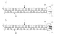
上記施工工程で構築された地山補強構造を有するトンネルの例を図6及び図7に示す。本例では、トンネルの掘削面54に沿って吹付コンクリート51が打設され、吹付コンクリート51から周囲の地山50にロックボルト1が放射状に打設されている。各ロックボルト1は、定着材53で地山50に定着されると共に、外挿された支圧プレート2が吹付コンクリート51に密着するように、略半球状の頭部13の前端面14が支圧プレート2に押し付けられている。そして、放射状に打設されたロックボルト1によってトンネル周囲の地山50に構築されたアーチ構造55により、トンネル空間56が支保されている。
An example of a tunnel with a natural ground reinforcement structure constructed by the above construction process is shown in Figures 6 and 7. In this example, sprayed
更に、本例では、ロックボルト1のトンネル内側に突出する略半球状の頭部13と支圧プレート2を覆うように不織布等のシート状の緩衝材57が敷設され、緩衝材72の内側に積層するように防水シート58が敷設されており、略半球状の頭部13を間接的に覆うように防水シート58が敷設されている。緩衝材57と防水シート58の敷設は、例えば緩衝材57をアンカーや釘等の留め具571で吹付コンクリート51に固定して吹付コンクリート51の内表面に沿って敷設し、この緩衝材57の固定により、点在する固定部で緩衝材57に固定されて緩衝材57に重ねて設けられている防水シート58を吹付コンクリート51の内表面に沿って敷設する。図示の59は覆工コンクリートである。
Furthermore, in this example, a sheet-
この防水シート58が敷設された地山補強構造では、地山50に設置された支圧プレート2は例えば吹付コンクリート51の表面から9~12mmの厚みで突出し、更に、支圧プレート2の内表面から略半球状の頭部13が例えば約30mmの高さで突出し、これらを覆うように緩衝材57、防水シート58が敷設されるが、ロックボルト1のトンネル周方向の打設ピッチは1mm以上離れているため、図6の模式例よりも実際の緩衝材57と防水シート58は凹凸の少ない敷設状態となる。尚、緩衝材57を敷設せずに、略半球状の頭部13や支圧プレート2を直接覆うように防水シート58を敷設する構成とすることも可能である。
In this natural ground reinforcement structure with the
このように地山50に打設、定着されたロックボルト1と、支圧プレート2を備えるトンネルの地山補強構造では、地山50が押し出してこようとする力Fを支圧プレート2で支え、ロックボルト1に生ずる引張方向の軸力Tによって抗することにより、アーチ構造55が壊れないように支保する(図7、図8(a)参照)。この際、ロックボルト1の略半球状の頭部13には、図8(b)に示す仮想的に取り出した円錐台16vの外周側面161vに対して垂直方向に引張荷重がかかることから、略半球状の頭部13の素材の引張強度に外周側面161vの面積Sを乗じた破断荷重を要求値を超えるように設定すると良い。
In this way, in a natural ground reinforcement structure for a tunnel equipped with a
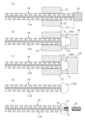
次に、本実施形態のロックボルト1に対する引抜試験について説明する。地山補強構造で打設された状態のロックボルト1に対して引抜試験を行う際には、例えば図9に示すように、地山50の表面に沿って吹付コンクリート51が打設され、吹付コンクリート51と地山50に削孔された穿孔52にロックボルト1が打設され、穿孔52内の定着材53でロックボルト1が定着されている地盤補強構造において、打設されたロックボルト1の略半球状の頭部13の雌ねじ部15にテンションロッド62を螺着する。図示例では、ロックボルト1の頭部13の前端面14で吹付コンクリート51に当接している支圧プレート2に載置するようにして略キャップ状の引抜試験用反力台座61のベースプレート611が設けられ、引抜試験用反力台座61の内部で、引抜試験用反力台座61の貫通穴から挿入されたテンションロッド62の先端部の雄ねじ部621とロックボルト1の頭部13の雌ねじ部15が螺着されている。
Next, a pull-out test for the
地山50と逆側に引抜試験用反力台座61から突出するテンションロッド62の部分には、センターホールジャッキ63、引抜試験用測定板64を外挿するように設け、テンションロッド62に引抜試験用押さえナット65を螺合して、引抜試験用測定板64の地山50と逆側への移動を規制する。
A
そして、センターホールジャッキ63の伸長方向の加圧により、引抜試験用測定板64、引抜試験用押さえナット65を介してテンションロッド62に引抜力を載荷する。これにより、引抜試験用反力台座61から反力を得て、テンションロッド62を介して頭部13からロックボルト1に引抜方向の力が加えられる。このようにロックボルト1に引抜力を載荷して、載荷荷重からロックボルト1に加えられた軸力を算出すると共に、引抜試験用測定板64の変位を測定することにより、ロックボルト1の伸びを認識し、ロックボルト1の引抜耐力、伸びを認識する。ロックボルト1の引抜耐力、伸びの認識は、相互の対応関係データを記憶部に格納するパーソナルコンピュータ、スマートフォン或いは専用端末等のコンピュータ装置で算出させ、出力部で出力するようにすると好適である。
Then, by applying pressure in the extension direction of the
本実施形態によれば、ロックボルト1の引抜試験の際には略半球状の頭部13の雌ねじ部15にテンションロッド62を螺着して行うことが可能となり、引抜試験時のナットの取り外しと再度の締め付けの作業を無くすことができ、簡単にロックボルト1の引抜試験を行うことができる。また、ナット締めの必要なく、地山50に押し込むだけでロックボルト1を施工することが可能であるから、ロックボルト1の打設作業に要する手間を低減することができる。また、ロックボルト1の頭部13が略半球状であるため、ロックボルト1の頭部13を直接若しくは間接的に覆うように敷設される防水シート58の破損を防止することができる。更に、支圧プレート2の角部22をアール面取りして形成することにより、ロックボルト1の頭部13と支圧プレート2を直接若しくは間接的に覆うように敷設される防水シート58の破損をより確実に防止することができる。
According to this embodiment, the pull-out test of the
また、ロックボルト1の軸部11の外形状と外周サイズを有する棒鋼材の一方の端部に、熱間鍛造で略半球状の頭部13を形成してロックボルト1を製造する場合には、略半球状の頭部13を軸部11と同一材料から形成することができることに加え、略半球状の頭部13に、軸部11から連続した熱間鍛造による鍛流線が形成された、内部組織が均質の材料構造、粘りの増した靭性に富む材料構造とすることができる。従って、高強度、高耐力を全長に亘って発揮するロックボルト1を得ることができる。また、熱間鍛造の製造により、迅速且つ安価にロックボルト1を製造することができる。
In addition, when manufacturing a
また、本実施形態のロックボルト1の施工方法では、支圧プレート2を地山50或いは吹付コンクリート51に密着させるまでナット締めをする必要が無く、ロックボルト1を押し込むように移動するだけでロックボルト1を打設することができることから、施工作業を容易化することができる。
In addition, with the method of installing the
また、ロックボルト1が打設された地盤補強構造において行うロックボルト1の引抜試験では、支圧プレート2に当接する頭部13にテンションロッド62を螺着して取り付けるだけで、ナットの取り外しと再度の締め付けの作業を行わずに、簡単にロックボルトの引抜試験を行うことができる。また、引抜試験完了後には、テンションロッド62をロックボルト1の頭部13から取り外すだけで簡単に原状復帰することができ、ナットの再度の締め付けの作業を不要にすることができる。
In addition, in a pull-out test of the
〔本明細書開示発明の包含範囲〕
本明細書開示の発明は、発明として列記した各発明、実施形態の他に、適用可能な範囲で、これらの部分的な内容を本明細書開示の他の内容に変更して特定したもの、或いはこれらの内容に本明細書開示の他の内容を付加して特定したもの、或いはこれらの部分的な内容を部分的な作用効果が得られる限度で削除して上位概念化して特定したものを包含する。そして、本明細書開示の発明には下記内容や変形例も含まれる。
[Scope of the invention disclosed herein]
The inventions disclosed in this specification include, in addition to the inventions and embodiments listed as inventions, those specified by changing partial contents of these to other contents disclosed in this specification, those specified by adding other contents disclosed in this specification to these contents, or those specified by deleting partial contents of these to the extent that partial effects can be obtained, and specifying them as a higher-level concept. The inventions disclosed in this specification also include the following contents and modifications.
例えば本発明のロックボルトは、上記実施形態のように頭部13を軸部11に熱間鍛造で一体的に形成した構成とすると好適であるが、例えば雌ねじ部15が形成される略半球状の頭部13に、軸部11の高張力材よりも高強度の材料を用い、軸部11の後側に別材料の頭部13を摩擦圧接して形成したロックボルト1としても良好である。また、これら以外の製造方法で形成したものも本発明の趣旨の範囲内で本発明のロックボルトに含まれ、例えば軸部11と同一形状で同一サイズの棒鋼材の一方の端面に略半球状の頭部13が溶接された構成のロックボルト、又は、略半球状の頭部13を軸部11に冷間鍛造など熱間鍛造以外で一体的に形成された構成のロックボルトとすることも可能である。
For example, the lock bolt of the present invention is preferably configured such that the
また、上記実施形態のロックボルト1の施工において、略半球状の頭部13の前端面14で支圧プレート2を押圧するロックボルト1の打設は、打設機42等でロックボルト1を自動的に押し込んで打設するようにすると良好であるが、ロックボルト1を人力で押し込んで打設、施工することも可能である。
In addition, in the installation of the
本発明は、例えばトンネルで打設するロックボルト、斜面に打設するロックボルト等に利用することができる。 The present invention can be used, for example, for rock bolts to be installed in tunnels and on slopes.
1…ロックボルト 11…軸部 12…剣先部 13…頭部 14…前端面 15…雌ねじ部 16v…円錐台 161v…外周側面 1m…異形棒鋼 11m…軸部 13m1、13m2…頭部 2…支圧プレート 21…挿通穴 22…角部 31、32…チャック、33…型内空間 34…第1の型、35…ストッパー、37…型内空間 38…第2の型 39…タップ 41…ガイドセル 42…打設機 50…地山 51…吹付コンクリート 52…穿孔 53…定着材 54…掘削面 55…アーチ構造 56…トンネル空間 57…緩衝材 571…留め具 58…防水シート 59…覆工コンクリート 61…引抜試験用反力台座 611…ベースプレート 62…テンションロッド 621…雄ねじ部 63…センターホールジャッキ 64…引抜試験用測定板 65…押さえナット T…軸力 F…地山が押し出してこようとする力 S…円錐台の外周側面の面積 101…トンネルの掘削面 102…吹付コンクリート 103…地山 104…ロックボルト 105…定着材 106…支圧プレート 107…雄ねじ 108…ナット 109…アーチ構造 110…トンネル空間
LIST OF
Claims (6)
前記頭部に前記軸部から連続した熱間鍛造による鍛流線が形成され、
前記頭部の前端面が前記軸部に外挿される支圧プレートを押圧可能に設けられていると共に、
引抜試験用のテンションロッドを螺着可能な雌ねじ部が、前記頭部に後端側から前記軸部と同軸となるように形成されていることを特徴とするロックボルト。 A substantially hemispherical head is formed integrally with the shaft portion by hot forging on the rear side in the casting direction of the shaft portion,
A hot forging process is performed on the head portion to form a continuous grain flow from the shaft portion,
The front end surface of the head portion is provided so as to be able to press a support plate that is fitted onto the shaft portion,
A lock bolt characterized in that a female threaded portion into which a tension rod for a pull-out test can be screwed is formed in the head from the rear end side so as to be coaxial with the shaft portion.
前記支圧プレートの角部がアール面取りされていることを特徴とするロックボルト構造体。 A bearing plate is fitted onto the shaft portion of the rock bolt according to claim 1,
A rock bolt structure characterized in that the corners of the support plate are chamfered with a radius.
前記軸部の外形状と外周サイズを有する棒鋼材の一方の端部に、熱間鍛造で略半球状の前記頭部を形成することを特徴とするロックボルトの製造方法。 A method for manufacturing a rock bolt according to claim 1,
A method for manufacturing a lock bolt, comprising the steps of: forming the approximately hemispherical head by hot forging at one end of a steel bar having the outer shape and outer peripheral size of the shaft portion.
前記ロックボルトの前記軸部に先端側から支圧プレートを外挿する第1工程と、
前記支圧プレートを前記頭部の前端面で地山に押し付けるようにして前記ロックボルトを前記地山に打設する第2工程を備えることを特徴とするロックボルトの施工方法。 A method for installing a rock bolt according to claim 1,
A first step of inserting a bearing plate from a tip side of the shaft portion of the rock bolt;
A rock bolt installation method comprising a second step of driving the rock bolt into the ground by pressing the front end surface of the head of the support plate against the ground.
前記軸部に外挿された前記支圧プレートが、略半球状の前記頭部の前端面と、地山若しくは吹付コンクリートの被打設面との間に介在する状態で、前記ロックボルトが地山に打設され、
略半球状の前記頭部を直接若しくは間接的に覆うように防水シートが敷設されていることを特徴とする地山補強構造。 A ground reinforcement structure in which the rock bolt according to claim 1 is driven,
The rock bolt is driven into the ground with the bearing plate inserted into the shaft portion between the front end surface of the substantially hemispherical head portion and the ground or the surface to be poured of sprayed concrete,
A ground reinforcement structure characterized in that a waterproof sheet is laid so as to directly or indirectly cover the approximately hemispherical head.
打設された状態の前記ロックボルトの前記頭部の雌ねじ部にテンションロッドを螺着する第1工程と、
前記テンションロッドを介して前記頭部に引抜方向の力を加え、前記ロックボルトの引抜耐力を認識する第2工程を備えることを特徴とする引抜試験方法。 A method for performing a pull-out test on the rock bolts installed in the natural ground reinforcement structure according to claim 5,
A first step of screwing a tension rod into the female thread portion of the head of the rock bolt in a driven state;
A pull-out test method comprising a second step of applying a force in a pull-out direction to the head via the tension rod and determining the pull-out strength of the rock bolt.
Priority Applications (1)
| Application Number | Priority Date | Filing Date | Title |
|---|---|---|---|
| JP2021032637A JP7601331B2 (en) | 2021-03-02 | 2021-03-02 | Rock bolt and its manufacturing method |
Applications Claiming Priority (1)
| Application Number | Priority Date | Filing Date | Title |
|---|---|---|---|
| JP2021032637A JP7601331B2 (en) | 2021-03-02 | 2021-03-02 | Rock bolt and its manufacturing method |
Publications (2)
| Publication Number | Publication Date |
|---|---|
| JP2022133760A JP2022133760A (en) | 2022-09-14 |
| JP7601331B2 true JP7601331B2 (en) | 2024-12-17 |
Family
ID=83229771
Family Applications (1)
| Application Number | Title | Priority Date | Filing Date |
|---|---|---|---|
| JP2021032637A Active JP7601331B2 (en) | 2021-03-02 | 2021-03-02 | Rock bolt and its manufacturing method |
Country Status (1)
| Country | Link |
|---|---|
| JP (1) | JP7601331B2 (en) |
Families Citing this family (1)
| Publication number | Priority date | Publication date | Assignee | Title |
|---|---|---|---|---|
| KR102493631B1 (en) * | 2022-10-24 | 2023-01-31 | (주)제이엠지테크 | Detecting rod to identify buried facilities |
Citations (3)
| Publication number | Priority date | Publication date | Assignee | Title |
|---|---|---|---|---|
| JP2005314993A (en) | 2004-04-30 | 2005-11-10 | Taisei Corp | Rock bolt |
| US20170314394A1 (en) | 2014-10-28 | 2017-11-02 | Fci Holdings Delaware, Inc. | End Coupling for a Rock Bolt |
| JP2019143404A (en) | 2018-02-22 | 2019-08-29 | 株式会社ケー・エフ・シー | Plate for rock bolt, rock bolt installation structure, rock bolt loading test method |
Family Cites Families (3)
| Publication number | Priority date | Publication date | Assignee | Title |
|---|---|---|---|---|
| JPS60104500U (en) * | 1983-12-19 | 1985-07-16 | 佐藤 創一郎 | Lock bolt for tunnel excavation |
| JPS6372446A (en) * | 1986-09-13 | 1988-04-02 | Fuikusaa Corp:Kk | Manufacture of anchor bolt |
| JPH10280899A (en) * | 1997-04-02 | 1998-10-20 | Kfc Ltd | Nut and bearing plate combination |
-
2021
- 2021-03-02 JP JP2021032637A patent/JP7601331B2/en active Active
Patent Citations (3)
| Publication number | Priority date | Publication date | Assignee | Title |
|---|---|---|---|---|
| JP2005314993A (en) | 2004-04-30 | 2005-11-10 | Taisei Corp | Rock bolt |
| US20170314394A1 (en) | 2014-10-28 | 2017-11-02 | Fci Holdings Delaware, Inc. | End Coupling for a Rock Bolt |
| JP2019143404A (en) | 2018-02-22 | 2019-08-29 | 株式会社ケー・エフ・シー | Plate for rock bolt, rock bolt installation structure, rock bolt loading test method |
Also Published As
| Publication number | Publication date |
|---|---|
| JP2022133760A (en) | 2022-09-14 |
Similar Documents
| Publication | Publication Date | Title |
|---|---|---|
| US9091064B1 (en) | Rebar anchorage device and method for connecting same to a rebar | |
| US4653132A (en) | Method of making plug-containing type internally threaded anchor | |
| JP4295349B2 (en) | Expansion anchor and its installation method | |
| EP3557209B1 (en) | Pulling device | |
| US6893196B2 (en) | Blind rivet nut and fastening unit | |
| US5556233A (en) | Rock anchor assembly | |
| JP4133826B2 (en) | Fastening method | |
| US20130097845A1 (en) | Expansion plug | |
| JP7601331B2 (en) | Rock bolt and its manufacturing method | |
| CA2763179C (en) | Tensionable tubular resin anchored tubular bolt and method | |
| EP3106583B1 (en) | Rebar anchorage device and method for connecting same to a rebar | |
| US20040161305A1 (en) | Radially deformed anchorage bolt | |
| US4784531A (en) | Bendable roof bolt without notch | |
| JP2006219912A (en) | Fixing structure between prestressing strand and socket, and device for press-fitting and fixing prestressing strand and wedge into socket | |
| US20120198683A1 (en) | Nail-shaped fastening element | |
| JP7651107B2 (en) | Rock bolt and its manufacturing method | |
| JP3983374B2 (en) | Anchor re-tension method and re-tension jig | |
| SE1750417A1 (en) | Strengthening Organs | |
| JP7467006B2 (en) | Rock bolt and its manufacturing method | |
| JP2024100538A (en) | Rock bolts and rock bolt structures | |
| CA2140196C (en) | Mechanical connection for reinforcing bars, device for placing this mechanical connection and process for fixing the mechanical connection for reinforcing bars | |
| CN113529817B (en) | Non-welding anti-pulling static load test method for prestressed pipe pile | |
| AU2002351425B2 (en) | Rock bolt | |
| US20110250977A1 (en) | Method for producing a screw foundation | |
| RU2854284C1 (en) | Blind bolt-rivet |
Legal Events
| Date | Code | Title | Description |
|---|---|---|---|
| A621 | Written request for application examination |
Free format text: JAPANESE INTERMEDIATE CODE: A621 Effective date: 20231213 |
|
| A977 | Report on retrieval |
Free format text: JAPANESE INTERMEDIATE CODE: A971007 Effective date: 20240725 |
|
| A131 | Notification of reasons for refusal |
Free format text: JAPANESE INTERMEDIATE CODE: A131 Effective date: 20240731 |
|
| A521 | Request for written amendment filed |
Free format text: JAPANESE INTERMEDIATE CODE: A523 Effective date: 20240819 |
|
| TRDD | Decision of grant or rejection written | ||
| A01 | Written decision to grant a patent or to grant a registration (utility model) |
Free format text: JAPANESE INTERMEDIATE CODE: A01 Effective date: 20241126 |
|
| A61 | First payment of annual fees (during grant procedure) |
Free format text: JAPANESE INTERMEDIATE CODE: A61 Effective date: 20241126 |
|
| R150 | Certificate of patent or registration of utility model |
Ref document number: 7601331 Country of ref document: JP Free format text: JAPANESE INTERMEDIATE CODE: R150 |
|
| S531 | Written request for registration of change of domicile |
Free format text: JAPANESE INTERMEDIATE CODE: R313531 |
|
| R350 | Written notification of registration of transfer |
Free format text: JAPANESE INTERMEDIATE CODE: R350 |