JP7467006B2 - Rock bolt and its manufacturing method - Google Patents
Rock bolt and its manufacturing method Download PDFInfo
- Publication number
- JP7467006B2 JP7467006B2 JP2020152660A JP2020152660A JP7467006B2 JP 7467006 B2 JP7467006 B2 JP 7467006B2 JP 2020152660 A JP2020152660 A JP 2020152660A JP 2020152660 A JP2020152660 A JP 2020152660A JP 7467006 B2 JP7467006 B2 JP 7467006B2
- Authority
- JP
- Japan
- Prior art keywords
- pull
- rock bolt
- head
- neck
- out test
- Prior art date
- Legal status (The legal status is an assumption and is not a legal conclusion. Google has not performed a legal analysis and makes no representation as to the accuracy of the status listed.)
- Active
Links
- 239000011435 rock Substances 0.000 title claims description 124
- 238000004519 manufacturing process Methods 0.000 title claims description 13
- 238000007586 pull-out test Methods 0.000 claims description 78
- 238000005242 forging Methods 0.000 claims description 27
- 229910000831 Steel Inorganic materials 0.000 claims description 26
- 239000010959 steel Substances 0.000 claims description 26
- 238000000034 method Methods 0.000 claims description 17
- 239000011378 shotcrete Substances 0.000 claims description 16
- 230000002787 reinforcement Effects 0.000 claims description 15
- 230000002093 peripheral effect Effects 0.000 claims description 5
- 238000009434 installation Methods 0.000 claims 1
- 239000000463 material Substances 0.000 description 22
- 238000003780 insertion Methods 0.000 description 18
- 230000037431 insertion Effects 0.000 description 18
- 238000010276 construction Methods 0.000 description 11
- 238000010586 diagram Methods 0.000 description 9
- 230000036961 partial effect Effects 0.000 description 6
- 238000005266 casting Methods 0.000 description 5
- 238000006243 chemical reaction Methods 0.000 description 5
- 238000004873 anchoring Methods 0.000 description 4
- 238000003825 pressing Methods 0.000 description 4
- 230000008569 process Effects 0.000 description 4
- 238000003466 welding Methods 0.000 description 4
- 230000007246 mechanism Effects 0.000 description 3
- 238000012360 testing method Methods 0.000 description 3
- 238000009412 basement excavation Methods 0.000 description 2
- 230000015572 biosynthetic process Effects 0.000 description 2
- 230000008878 coupling Effects 0.000 description 2
- 238000010168 coupling process Methods 0.000 description 2
- 238000005859 coupling reaction Methods 0.000 description 2
- 239000013078 crystal Substances 0.000 description 2
- 230000006870 function Effects 0.000 description 2
- 239000007769 metal material Substances 0.000 description 2
- 238000013459 approach Methods 0.000 description 1
- 238000010273 cold forging Methods 0.000 description 1
- 238000004891 communication Methods 0.000 description 1
- 238000009430 construction management Methods 0.000 description 1
- 230000007547 defect Effects 0.000 description 1
- 238000006073 displacement reaction Methods 0.000 description 1
- 238000005553 drilling Methods 0.000 description 1
- 238000011900 installation process Methods 0.000 description 1
- 230000002452 interceptive effect Effects 0.000 description 1
- 238000005304 joining Methods 0.000 description 1
- 238000005259 measurement Methods 0.000 description 1
- 238000012986 modification Methods 0.000 description 1
- 230000004048 modification Effects 0.000 description 1
- 239000004570 mortar (masonry) Substances 0.000 description 1
- 239000002994 raw material Substances 0.000 description 1
- 239000011347 resin Substances 0.000 description 1
- 229920005989 resin Polymers 0.000 description 1
Images


Landscapes
- Piles And Underground Anchors (AREA)
- Investigating Strength Of Materials By Application Of Mechanical Stress (AREA)
Description
本発明は、例えばトンネル空間の支保に用いられるロックボルト及びその製造方法に関する。 The present invention relates to rock bolts used, for example, to support tunnel spaces, and to a method for manufacturing the same.
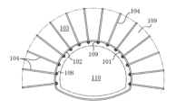
一般的なトンネルでは、図8及び図9に示すように、トンネルの掘削面101に沿って吹付コンクリート102が打設され、吹付コンクリート102から周囲の地山103にロックボルト104が放射状に打設される。各ロックボルト104は、定着材105で地山103に定着されると共に、外挿された支圧プレート106が吹付コンクリート102に密着するように、後端部の雄ねじ107にナット108が嵌められる。そして、放射状に打設されたロックボルト104によってトンネル周囲の地山103に構築されたアーチ構造109により、トンネル空間110が支保される。
In a typical tunnel, as shown in Figures 8 and 9, sprayed
地山103に打設、定着されたロックボルト104は、地山103が押し出してこようとする力Fに対して、ロックボルト104に生ずる引張方向の軸力Tによって抗することにより、アーチ構造109が壊れないように支保する。このようなロックボルト104の機能を発現するには、ロックボルト104が地山103に所要の引抜耐力を有する状態で強固に定着されていることが重要となる。更に、ロックボルト104が破断しないことや、支圧プレート106が吹付コンクリート102に密着するようにロックボルト104にナット締めがされていることも必要となる。
The
また、特許文献1では、ロックボルトの施工におけるナット締めの作業を省略するため、ロックボルトの後端部に円形の平鋼板からなるプレート固定部材を一体的に接合し、このプレート固定部材で支圧プレートを押さえつけるロックボルトが提案されている。
ところで、上述のように、地山103に打設されたロックボルト104では、所要の引抜耐力を有する状態で打設されていることを確認するため、施工管理上の仕様に従って引抜試験が行われる。ナット締め方式のロックボルト104に対する引抜試験では、支圧プレート106を押圧するナット108を取り外し、ロックボルト104の後端部の雄ねじ107にカップリングを介してテンションバーを接続し、そのテンションバーをセンターホールラムに挿通して油圧ジャッキで載荷することにより、ロックボルトに引張力をかけ、所定の引抜強度まで抜けてこないかの計測を行う。所定の引抜試験まで抜けてこないことを確認した後には、カップリング、テンションバー、センターホールラム、油圧ジャッキで構成される試験装置をロックボルト104から取り外し、支圧プレート106を押圧するナット108をロックボルト104の雄ねじ107に再度締め付ける。
As described above, the
このような引抜試験は、地山103に打設した全てのロックボルト104からサンプリングした一部のロックボルト104に対して行うのが通常であるが、サンプリングしたロックボルト104に対して行うにしても、ロックボルト104からナット108を取り外し、原状復帰のために再度締め付ける作業にはかなりの手間がかかる。尚、特許文献1のロックボルトは、後端部に支圧プレートを押さえつける平鋼板のプレート固定部材が一体的に接合されているため、引抜試験を行うこと自体が困難である。
This type of pull-out test is usually performed on a sample of all
また、1本1本のロックボルト104が支えられる荷重を増やすために、ロックボルトの高耐力化が要望されることがあるが、ロックボルト104の軸部に所望の引張強度が得られたとしても、軸部より強度の低い雄ねじ107の部分が破断するとロックボルトとして機能しなくなるため、軸部より強度の低い箇所を無くすことも重要である。
In addition, in order to increase the load that each
本発明は上記課題に鑑み提案するものであって、引抜試験を行う際のナットの取り外しと再度の締め付けの作業を無くすことができ、簡単に引抜試験を行うことができると共に、全長に亘って高強度、高耐力を発揮することができるロックボルト及びその製造方法を提供することを目的とする。 The present invention has been proposed in consideration of the above problems, and aims to provide a rock bolt and a manufacturing method thereof that can eliminate the need to remove and re-tighten the nut when conducting a pull-out test, allows for easy pull-out testing, and exhibits high strength and high durability over its entire length.
本発明のロックボルトは、軸部の打設方向における後側に前記軸部に対してフランジ状に突出する首部が形成され、前記首部の先端が前記軸部に外挿される支圧プレートを押圧可能に設けられていると共に、前記首部の後側に前記首部に対して少なくとも一部がフランジ状に突出する頭部が形成され、引抜試験治具を取付可能な前記頭部が前記首部及び前記軸部と一体的に形成されていることを特徴とする。
これによれば、支圧プレートを押圧する首部の後側でフランジ状に突出する頭部に引抜試験治具を取り付けることにより、ナットの取り外しと再度の締め付けの作業を行わずに、簡単に引抜試験を行うことができる。また、頭部が首部に対してフランジ状に突出していることから、引抜試験治具の取り付けを容易に行うことができる。また、ナットを螺合する雄ねじの形成が不要で、軸部よりも局所的に強度が劣る箇所を形成する必要が無いことから、ロックボルトの全長に亘って高強度、高耐力を発揮することができる。
The rock bolt of the present invention is characterized in that a neck portion is formed on the rear side of the shank in the pouring direction so as to protrude like a flange from the shank, the tip of the neck is capable of pressing a support plate inserted into the shank, and a head portion is formed on the rear side of the neck so that at least a portion of the head protrudes like a flange from the neck, and the head portion to which a pull-out test jig can be attached is formed integrally with the neck and the shank .
According to this, by attaching a pull-out test jig to the head that protrudes like a flange behind the neck that presses the support plate, a pull-out test can be easily performed without removing the nut and tightening it again. Also, since the head protrudes like a flange from the neck, the pull-out test jig can be easily attached. Also, since it is not necessary to form a male thread to screw the nut, and there is no need to form a part that is locally weaker than the shaft, the rock bolt can exhibit high strength and high durability over its entire length.
本発明のロックボルトは、前記頭部が略楕円鍔状に形成されていることを特徴とする。
これによれば、例えば引抜試験治具の略楕円形の挿通穴に頭部を挿入し、挿通穴の後側の略円形の係合溝で頭部を相対的に回転する等により、頭部と引抜試験治具の取り付けを非常に容易に行うことができる。
The lock bolt of the present invention is characterized in that the head is formed into a substantially elliptical flange shape.
This makes it very easy to attach the head to the pull-out test jig, for example by inserting the head into the approximately elliptical insertion hole of the pull-out test jig and rotating the head relatively using the approximately circular engagement groove at the rear of the insertion hole.
本発明のロックボルトの製造方法は、本発明のロックボルトを製造する方法であって、前記軸部の外形状と外周サイズを有する棒鋼材の一方の端部に、熱間鍛造で前記首部と前記頭部を形成することを特徴とする。
これによれば、首部と頭部を軸部と同一材料から形成することができることに加え、首部と頭部に、軸部から連続した熱間鍛造による鍛流線が形成された、内部組織が均質の材料構造、粘りの増した靭性に富む材料構造とすることができる。更に、首部と頭部には、雄ねじの形成等による結晶構造の欠損が無いことから、内部組織が均質の材料構造、粘りの増した靭性に富む材料構造を軸部から連続して首部と頭部の全体で確保することができる。従って、ロックボルトの高強度、高耐力を全長に亘ってより確実に発揮することができる。また、熱間鍛造の製造により、迅速且つ安価に本発明のロックボルトを製造することができる。
The manufacturing method of the rock bolt of the present invention is a method of manufacturing the rock bolt of the present invention, characterized in that the neck portion and the head are formed by hot forging at one end of a steel bar material having the outer shape and outer peripheral size of the shaft portion.
According to this, the neck and head can be formed from the same material as the shaft, and the neck and head can have a material structure with homogeneous internal structure and high toughness with increased viscosity, in which grain flows are formed by hot forging that continue from the shaft. Furthermore, since there is no crystal structure loss due to the formation of a male thread, etc., the neck and head can have a homogeneous internal structure and a material structure with increased toughness that continues from the shaft, and the entire neck and head can be secured. Therefore, the high strength and high yield strength of the rock bolt can be more reliably exhibited over the entire length. Furthermore, the lock bolt of the present invention can be manufactured quickly and inexpensively by manufacturing it by hot forging.
本発明のロックボルトの施工方法は、本発明のロックボルトを施工する方法であって、前記ロックボルトの前記軸部に先端側から支圧プレートを外挿する第1工程と、前記支圧プレートを前記首部の先端で押すように前記ロックボルトを地山に打設する第2工程を備えることを特徴とする。
これによれば、支圧プレートを地山或いは吹付コンクリートに密着させるまでナット締めをする必要が無く、ロックボルトを押し込むように移動するだけでロックボルトを打設することができることから、施工作業を容易化することができる。また、ロックボルトの軸部の先端付近に支圧プレートを外挿するだけで施工可能であることから、ロックボルトに打撃力を加えて押し込むタイプの打設機を備える打設機構に支圧プレートを干渉させずにセットすることができ、この種の打設機による機械施工を行うこともできる。
The method of installing a rock bolt of the present invention is a method of installing a rock bolt of the present invention, characterized in that it comprises a first step of extrapolating a support plate from the tip side onto the shaft portion of the rock bolt, and a second step of driving the rock bolt into the ground so as to press the support plate with the tip of the neck.
This makes it possible to facilitate construction work by eliminating the need to tighten the nuts until the bearing plate is in close contact with the ground or sprayed concrete, and by simply moving the rock bolt in a pushing motion. Also, since construction can be performed simply by inserting the bearing plate around the tip of the shaft of the rock bolt, the bearing plate can be set without interfering with a driving mechanism that includes a driving machine that applies a striking force to the rock bolt to push it in, and mechanical construction can be performed using this type of driving machine.
本発明の地山補強構造は、本発明のロックボルトが打設される地山補強構造であって、前記軸部に外挿された前記支圧プレートが、前記首部の先端と、地山若しくは吹付コンクリートの被打設面との間に介在する状態で、前記ロックボルトが地山に打設されていることを特徴とする。
これによれば、地山補強構造で打設されたロックボルトにおいて、支圧プレートに当接する首部の後側でフランジ状に突出する頭部に引抜試験治具を取り付けることにより、ナットの取り外しと再度の締め付けの作業を行わずに、簡単に引抜試験を行うことができる。また、地山補強構造で打設されたロックボルトでは頭部が首部に対してフランジ状に突出していることから、引抜試験治具の取り付けを容易に行うことができる。また、全長に亘って高強度、高耐力を発揮するロックボルトが打設された地山補強構造を得ることができる。
The ground reinforcement structure of the present invention is a ground reinforcement structure in which a rock bolt of the present invention is driven, and is characterized in that the rock bolt is driven into the ground with the support plate inserted into the shaft portion being interposed between the tip of the neck portion and the ground or the surface to be poured of sprayed concrete.
According to this, by attaching a pull-out test jig to the head of a rock bolt that protrudes like a flange behind the neck that abuts against the support plate, a pull-out test can be easily performed without removing and re-tightening the nut. In addition, since the head of a rock bolt that is driven into a natural ground reinforcement structure protrudes like a flange from the neck, the pull-out test jig can be easily attached. It is also possible to obtain a natural ground reinforcement structure in which a rock bolt that exhibits high strength and high resistance over its entire length is driven into the natural ground.
本発明の引抜試験方法は、本発明の地山補強構造で打設されている前記ロックボルトの引抜試験方法であって、打設された状態の前記ロックボルトの前記頭部に引抜試験治具を係合して取り付ける第1工程と、前記引抜試験治具を介して前記頭部に引抜方向の力を加え、前記ロックボルトの引抜耐力を認識する第2工程を備えることを特徴とする。
これによれば、打設された状態のロックボルトの頭部に引抜試験治具を係合して取り付けるだけで、ナットの取り外し作業を行わずに、簡単に引抜試験を行うことができる。また、引抜試験完了後には、引抜試験治具を頭部から取り外すだけで簡単に原状復帰することができ、ナットの再度の締め付けの作業を不要にすることができる。
The pull-out test method of the present invention is a pull-out test method for the rock bolt that is driven into the ground reinforcement structure of the present invention, and is characterized in that it comprises a first step of engaging and attaching a pull-out test jig to the head of the rock bolt in the driven state, and a second step of applying a force in the pull-out direction to the head via the pull-out test jig to determine the pull-out strength of the rock bolt.
According to this, a pull-out test can be easily performed by simply engaging and attaching the pull-out test jig to the head of the driven rock bolt without removing the nut. In addition, after the pull-out test is completed, the original state can be easily restored by simply removing the pull-out test jig from the head, making it unnecessary to tighten the nut again.
本発明のロックボルトによれば、引抜試験を行う際のナットの取り外しと再度の締め付けの作業を無くすことができ、簡単に引抜試験を行うことができると共に、全長に亘って高強度、高耐力を発揮することができる。 The lock bolt of the present invention eliminates the need to remove and re-tighten the nut when conducting a pull-out test, making it easy to conduct the pull-out test and providing high strength and durability over the entire length.
〔実施形態のロックボルト〕
本発明による実施形態のロックボルト1は、金属材或いは棒鋼材である異形棒鋼から構成され、図1及び図2に示すように、異形棒鋼の形状である軸部2の打設方向の後側に首部3と頭部4が順に形成されている。首部3は、軸部2に対してフランジ状に突出して形成されており、本実施形態では、略短尺円柱状或いは略円板状で、異形棒鋼の軸部2の最大径で構成される外周の外径よりも大径で首部3が形成されていると共に、首部3は軸部2と同軸で形成されている。首部3は、その先端の先端面31が軸部2に外挿される後述の支圧プレート51を押すことが出来るように、即ち首部3の外径は支圧プレート51に形成された軸部2の挿通穴よりも大径をなすように設けられ、本実施形態における先端面31は平坦面になっている。
[Lock bolt of embodiment]
The
頭部4は、首部3の後側に形成され、首部3に対して少なくとも一部がフランジ状に突出して形成されている。本実施形態における頭部4は、ロックボルト1の軸方向視で略楕円形の略楕円鍔状に形成されており、頭部4の略楕円形の短径は首部3の外径と略同一長さで形成されていると共に、その長径は首部3の外径よりも長く形成され、頭部4は長軸方向LAの一部が首部3に対してフランジ状に突設されている。長軸方向LAの片側における首部3の周面に対する頭部4の周面の一部の最大突出量は、例えば5mmなど3mm以上10mm以下とすると、所要の突出量を確保して後述する引抜試験治具の取り付けを容易にすることができると共に、頭部4を防水シートで覆って地山補強構造を構築する場合に頭部4の出っ張りを少なくして防水シートの引っ掛かりや破損を防止することができて好適である。また、本実施形態における頭部4は、ロックボルト1の軸方向における厚みが首部3の厚みよりも薄く形成されている。頭部4は、首部3及び軸部2と同軸で形成されている。
The
更に、本実施形態のロックボルト1では、首部3と頭部4が軸部2と一体的に形成されており、軸部2の後側に熱間鍛造によって首部3と頭部4が一体的に形成されている。
Furthermore, in the
軸部2の後側に熱間鍛造によって首部3と頭部4が一体的に形成された本実施形態のロックボルト1を製造する場合、素材として軸部2の外形状と外周サイズを有す棒状の金属材或いは棒鋼材が用いられ、例えば図3(a)に示す異形棒鋼1mが用いられる。異形棒鋼1mは高張力の異形棒鋼とすると好適であり、JIS G3112に規定された高張力異形棒鋼とするとより好適である。
When manufacturing the
そして、上型と下型など一対の鍛造型61、62を少し拡げた状態にして高熱に加熱した異形棒鋼1mを鍛造型61、62の間に挿入し、鍛造型61、62に対して挿入側と逆側に異形棒鋼1mの一方の端部を所定長だけ突出させた状態に配置し、鍛造型61、62で強固に挟み込む(図3(a)参照)。この一対の鍛造型61、62の異形棒鋼1mの突出側寄りの内部には、型内空間63が設けられており、型内空間63は、首部3に対応する形状とサイズの部分と、頭部4に対応する形状で且つ頭部4の厚みよりも2~3mm程度深いサイズの部分を有する。
Then, a pair of forging dies 61, 62, such as upper and lower dies, are slightly spread apart, and the highly heated
その後、異形棒鋼1mを突出側から型内空間63に2乃至3mm程度入り込むパンチ64で押し潰して熱間鍛造を行う。この熱間鍛造によって異形棒鋼1mの一方の端部に首部3と頭部4を一体的に形成、換言すれば軸部2の後側に熱間鍛造によって首部3と頭部4を一体的に形成する(図3(b)参照)。首部3と頭部4の形成後には、パンチ64を撤退させると共に一対の鍛造型61、62を開いて脱型し、パンチ64が撤退した方向に突出した不要なバリ65を取り除くことにより、本実施形態のロックボルト1を得る(図3(b)、(c)参照)。尚、本実施形態のロックボルト1を熱間鍛造で形成する場合の熱間鍛造は、本発明の趣旨の範囲内で適宜であり、例えば鍛造型を用いない自由鍛造の熱間鍛造とすることも可能である。
Then, the
このように軸部2の後側に熱間鍛造によって首部3と頭部4が一体的に形成されたロックボルト1の例として、JIS G3112に規定された高張力異形棒鋼SD345で呼び径22mmのD22の異形棒鋼1mを素材とするロックボルト1では、引張強度133.5kNを得ることができた。これに対して、SD345、D22の同種の異形棒鋼で一方の端部に雄ねじのねじ部が形成されたロックボルトの場合には、ねじ部が引張強度、降伏点の制約、ボトルネックとなり、引張強度は105kNであった。そのため、引張強度の規格値が120kNの場合、本実施形態のロックボルト1は規格値をクリアできるものの、SD345、D22の異形棒鋼による既存のロックボルトでは規格値をクリアすることができない。
As an example of a
SD345で呼び径25mmのD25の異形棒鋼で一方の端部に雄ねじのねじ部が形成された既存のロックボルトの場合には、引張強度122kNが得られ、規格値120kNをクリアすることはできる。しかしながら、引張強度の規格値が120kNをクリアするために、大径でサイズが大きく、重量の重いロックボルトを使用する必要があり、ロックボルト1を打設する際の穿孔の削孔径も大きく形成する必要がある。本実施形態のロックボルト1を用いれば、より小径で軽量なロックボルト1で引張強度の規格値をクリアすることができると共に、ロックボルト1を打設する際の穿孔の削孔径をより小さくでき、ロックボルト1を打設する施工作業を容易化することができる。
In the case of an existing rock bolt made of SD345, D25 deformed steel bar with a nominal diameter of 25 mm and a male thread formed at one end, a tensile strength of 122 kN is obtained, which is sufficient to clear the standard value of 120 kN. However, in order to clear the standard value of 120 kN for the tensile strength, it is necessary to use a rock bolt that is large in diameter, large in size, and heavy in weight, and the drilled hole diameter when driving the
次に、本実施形態のロックボルト1の施工工程について説明する。ロックボルト1を施工する際には、図4(a)、(b)に示すように、ロックボルト1の軸部2に打設方向の先端側から貫通穴を有する支圧プレート51を外挿し、必要に応じてロックボルト1を打設し易くするために先端が略山形の樹脂製等のキャップ52を軸部2の先端部に外嵌する。支圧プレート51はロックボルト1の首部3に近づけるように移動せずとも良く、支圧プレート51は軸部2の先端面の付近或いは先端面寄りに配置して外挿した状態とする。尚、必要に応じて、キャップ52を軸部2に外嵌する構成に代え、軸部2の先端を略山形に形成する構成等としてもよい。また、地山10、或いは地山10と吹付コンクリート11には予め穿孔12を形成し、穿孔12内に図示省略するモルタル等の定着材を予め注入しておく。
Next, the construction process of the
そして、図4(c)に示すように、ガイドセル71に沿ってスライド移動する押し込み式の打設機72でロックボルト1の後端部を保持し、打設機72を地山10に向かって前進させ、定着材が注入されている穿孔12に先端部側或いはキャップ52側からロックボルト1を押し込んでいく。ロックボルト1の押し込みは、首部3の先端面31で支圧プレート51を押しながら行い、支圧プレート51が首部3の先端と地山10或いは吹付コンクリート11の被打設面(地山10の表面或いは吹付コンクリート11の表面)との間に介在するように、望ましくは支圧プレート51が被打設面に密着するまで首部3を介してロックボルト1を押し込んで、地山10に打設する(図4(d))。即ち、この施工工程で構築された地山補強構造では、軸部2に外挿された支圧プレート51が首部3の先端と地山10或いは吹付コンクリート11の被打設面との間に介在して、地山10が押し出してきたときに支圧プレート51が押し出し力を受けることが出来るように、ロックボルト1が地山10に打設される。
As shown in Fig. 4(c), the rear end of the
次に、本実施形態のロックボルト1に対する引抜試験について説明する。引抜試験では、ロックボルト1の頭部4に係合して取り付けられる引抜試験治具8が用いられる(図5参照)。図示例の引抜試験治具8は、略円柱状の短尺柱状の外形を有し、軸方向の一方の端部から後述するテンションロッド92を着脱可能に螺着して接続するための接続穴81が有底穴状で形成されている。
Next, a pull-out test for the
引抜試験治具8の軸方向の他方の端部には、ロックボルト1の頭部4の軸方向視における略楕円形と略同一形状の略楕円形であり、且つ頭部4の略楕円形状よりも僅かにサイズが大きい挿通穴82が形成されている。引抜試験治具8の挿通穴82の奥側には略円形或いは略円盤状の係合溝83が形成されており、挿通穴82と係合溝83は連通して形成されている。係合溝83の内径は、挿通穴82の長径と略同一長さで形成されている。
At the other axial end of the pull-out
図示例の引抜試験治具8は、略楕円形の挿通穴82の長軸方向と略楕円形の頭部4の長軸方向を合わせるように配置して、略楕円形の挿通穴82をロックボルト1の略楕円形の頭部4に外挿し、更に、略円形の係合溝83を略楕円形の頭部4に外挿する。そして、引抜試験治具8を周方向に約90度回転させて、頭部4が係合溝83に配置されている状態で係合溝83を頭部4に対して相対的に約90度回転させ、ロックボルト1の略楕円形の頭部4の長軸方向に対して略楕円形の挿通穴82の短軸方向が対応して配置させることにより、引抜試験治具8がロックボルト1の頭部4に着脱可能で且つ軸方向に離脱しないように係合して取り付けられる(図5(c)、(d)参照)。図5中、84は引抜試験治具8の回転動作の目印となるマークである。
The pull-out
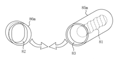
この引抜試験治具8は、例えば図6に示すように、接続穴81と係合溝83が形成された中間材85mと、略楕円形の挿通穴82が形成された中間材86mを摩擦圧接等で接合して形成してもよく、或いは、略円柱形の素材に、接続穴81、挿通穴82、係合溝83を中ぐり加工して形成してもよい。また、本実施形態のロックボルト1に対する引抜試験で用いる引抜試験治具は、接続穴81が形成される構成ではなく、接続穴81の開口に対応する部位にテンションロッドが接合されている構成のものとしてもよい。
As shown in FIG. 6, the pull-out
地山補強構造で打設された状態のロックボルト1に対して引抜試験を行う際には、例えば図7に示すように、地山10の表面に沿って吹付コンクリート11が打設され、吹付コンクリート11と地山10に削孔された穿孔12にロックボルト1が打設され、穿孔12内の定着材13でロックボルト1が定着されている地盤補強構造において、打設されたロックボルト1の頭部4に引抜試験治具8を上述のように係合して取り付ける。図示例では、ロックボルト1の首部3の先端面31で吹付コンクリート11に当接している支圧プレート51に載置するようにして引抜試験用反力台座91のベースプレート911が設けられている。この引抜試験用反力台座91はロックボルト1の頭部4に取り付けられた引抜試験治具8を収容し、接続穴81に螺着されるテンションロッド92が挿通自在な貫通穴を有するキャップ状を呈している。引抜試験治具8は、ロックボルト1の首部3が挿通穴82に配置され、頭部4が係合溝83に配置された状態で、ロックボルト1に係合して取り付けられている。
When performing a pull-out test on a
引抜試験治具8の接続穴81にはテンションロッド92を螺着し、地山10と逆側に引抜試験治具8から突出するテンションロッド92の部分には、センターホールジャッキ93、引抜試験用測定板94を外挿するように設け、テンションロッド92に引抜試験用押さえナット95を螺合して、引抜試験用測定板94の地山10と逆側への移動を規制する。
A
そして、センターホールジャッキ93の伸長方向の加圧により、引抜試験用測定板94、引抜試験用押さえナット95を介してテンションロッド92に引抜力を載荷する。これにより、引抜試験用反力台座91から反力を得て、テンションロッド92、引抜試験治具8を介して頭部4からロックボルト1に引抜方向の力が加えられる。このようにロックボルト1に引抜力を載荷して、載荷荷重からロックボルト1に加えられた軸力を算出すると共に、引抜試験用測定板94の変位を測定することにより、ロックボルト1の伸びを認識し、ロックボルト1の引抜耐力、伸びを認識する。ロックボルト1の引抜耐力、伸びの認識は、相互の対応関係データを記憶部に格納するパーソナルコンピュータ、スマートフォン或いは専用端末等のコンピュータ装置で算出させ、出力部で出力するようにすると好適である。
Then, by applying pressure in the extension direction of the
本実施形態のロックボルト1やロックボルト1を打設する地盤補強構造によれば、支圧プレート51を押圧する首部3の後側でフランジ状に突出する頭部4に引抜試験治具8を取り付けることにより、ナットの取り外しと再度の締め付けの作業を行わずに、簡単に引抜試験を行うことができる。また、頭部4が首部3に対してフランジ状に突出していることから、引抜試験治具8の取り付けを容易に行うことができる。また、ナットを螺合する雄ねじの形成が不要で、軸部2よりも局所的に強度が劣る箇所を形成する必要が無いことから、ロックボルト1の全長に亘って高強度、高耐力を発揮することができる。
According to the
また、ロックボルト1の頭部4を略楕円鍔状に形成することにより、引抜試験治具8の略楕円形の挿通穴82に頭部4を挿入し、挿通穴82の後側の略円形の係合溝83で頭部4を相対的に回転することにより、頭部4と引抜試験治具8の取り付けを非常に容易に行うことができる。
In addition, by forming the
また、軸部2の外形状と外周サイズを有する棒鋼材の一方の端部に、熱間鍛造で首部3と頭部4を形成してロックボルト1を製造する場合には、首部3と頭部4を軸部2と同一材料から形成することができることに加え、首部3と頭部4に、軸部から連続した熱間鍛造による鍛流線が形成された、内部組織が均質の材料構造、粘りの増した靭性に富む材料構造とすることができる。更に、首部3と頭部4には、雄ねじの形成等による結晶構造の欠損が無いことから、内部組織が均質の材料構造、粘りの増した靭性に富む材料構造を軸部から連続して首部3と頭部4の全体で確保することができる。従って、ロックボルト1の高強度、高耐力を全長に亘ってより確実に発揮することができる。また、熱間鍛造の製造により、迅速且つ安価にロックボルト1を製造することができる。
In addition, when manufacturing a
また、本実施形態のロックボルト1の施工方法では、支圧プレート51を地山10或いは吹付コンクリート11に押し付けるようにナット締めをする必要が無く、ロックボルト1を押し込むように移動するだけでロックボルト1を打設することができることから、施工作業を容易化することができる。また、ロックボルト1の軸部2の先端付近に支圧プレート51を外挿するだけで施工可能であることから、ロックボルト1に打撃力を加えて押し込むタイプの打設機72を備える打設機構に支圧プレート51を干渉させずにセットすることができ、この種の打設機による機械施工を行うこともできる。
In addition, in the construction method of the
また、ロックボルト1が打設された地盤補強構造において行うロックボルト1の引抜試験では、打設された状態のロックボルト1の頭部4に引抜試験治具8を係合して取り付けるだけで、ナットの取り外し作業を行わずに、簡単に引抜試験を行うことができる。また、引抜試験完了後には、引抜試験治具8を頭部4から取り外すだけで簡単に原状復帰することができ、ナットの再度の締め付けの作業を不要にすることができる。
In addition, in a pull-out test of the
〔本明細書開示発明の包含範囲〕
本明細書開示の発明は、発明として列記した各発明、実施形態の他に、適用可能な範囲で、これらの部分的な内容を本明細書開示の他の内容に変更して特定したもの、或いはこれらの内容に本明細書開示の他の内容を付加して特定したもの、或いはこれらの部分的な内容を部分的な作用効果が得られる限度で削除して上位概念化して特定したものを包含する。そして、本明細書開示の発明には下記内容や変形例も含まれる。
[Scope of the invention disclosed herein]
The inventions disclosed in this specification include, in addition to the inventions and embodiments listed as inventions, those specified by changing partial contents of these to other contents disclosed in this specification, those specified by adding other contents disclosed in this specification to these contents, or those specified by deleting partial contents of these to the extent that partial effects can be obtained, and forming a generic concept. The inventions disclosed in this specification also include the following contents and modifications.
例えば本発明のロックボルトは、上記実施形態のように首部3と頭部4を軸部2に熱間鍛造で一体的に形成した構成とすると好適であるが、本発明のロックボルトには、例えば軸部2と同一形状で同一サイズの棒鋼材の一方の端面に、首部3と頭部4が順次溶接等で接合される構成、若しくは、首部3と頭部4の一体成形体が溶接等で接合される構成も含まれ、又、軸部2と首部3が一体的に形成された中間材における首部3の後端面に頭部4が溶接等で接合される構成も含まれ、又、例えば首部3と頭部4を軸部2に冷間鍛造など熱間鍛造以外で一体的に形成された構成も含まれる。
For example, the lock bolt of the present invention is preferably configured such that the
また、本発明のロックボルトには、首部の後側に首部に対して少なくとも一部がフランジ状に突出する頭部が形成される適宜の構成が含まれ、例えば頭部の全体が全周に亘って首部に対してフランジ状に突出する構成も含まれる。また、首部に対して少なくとも一部がフランジ状に突出する頭部を形成する場合の頭部の形状は略楕円鍔状以外のものとすることも可能である。 The lock bolt of the present invention also includes an appropriate configuration in which a head is formed on the rear side of the neck, at least a portion of which protrudes in a flange-like manner from the neck, and also includes a configuration in which the entire head protrudes in a flange-like manner from the neck around the entire circumference. In addition, when forming a head at least a portion of which protrudes in a flange-like manner from the neck, the shape of the head can be other than a generally elliptical brim shape.
また、上記実施形態のロックボルト1の施工において、首部3の先端面31で支圧プレート51を押圧する押し込むロックボルト1の打設は、打設機72等で自動的に押し込んで打設するようにすると良好であるが、人力で押し込んで打設、施工することも可能である。
In addition, in the construction of the
本発明は、例えばトンネルで打設するロックボルト、斜面に打設するロックボルト等に利用することができる。 The present invention can be used, for example, for rock bolts to be installed in tunnels and on slopes.
1…ロックボルト 1m…異形棒鋼 2…軸部 3…首部 31…先端面 4…頭部 51…支圧プレート 52…キャップ 61、62…鍛造型 63…型内空間 64…パンチ 65…バリ 71…ガイドセル 72…打設機 8…引抜試験治具 81…接続穴 82…挿通穴 83…係合溝 84…マーク 85m、86m…中間材 91…引抜試験用反力台座 911…ベースプレート 92…テンションロッド 93…センターホールジャッキ 94…引抜試験用測定板 95…引抜試験用押さえナット 10…地山 11…吹付コンクリート 12…穿孔 13…定着材 LA…長軸方向 101…トンネルの掘削面 102…吹付コンクリート 103…地山 104…ロックボルト 105…定着材 106…支圧プレート 107…雄ねじ 108…ナット 109…アーチ構造 110…トンネル空間 T…軸力 F…地山が押し出してこようとする力
LIST OF
Claims (6)
前記首部の先端が前記軸部に外挿される支圧プレートを押圧可能に設けられていると共に、
前記首部の後側に前記首部に対して少なくとも一部がフランジ状に突出する頭部が形成され、
引抜試験治具を取付可能な前記頭部が前記首部及び前記軸部と一体的に形成されていることを特徴とするロックボルト。 A neck portion is formed on the rear side of the shaft portion in the pouring direction so as to protrude in a flange shape relative to the shaft portion,
The tip of the neck portion is provided so as to be able to press a support plate that is fitted onto the shaft portion,
A head portion is formed on the rear side of the neck portion, the head portion having at least a portion thereof protruding in a flange shape relative to the neck portion ,
A lock bolt, characterized in that the head, to which a pull-out test jig can be attached, is formed integrally with the neck and the shaft .
前記軸部の外形状と外周サイズを有する棒鋼材の一方の端部に、熱間鍛造で前記首部と前記頭部を形成することを特徴とするロックボルトの製造方法。 A method for manufacturing a rock bolt according to claim 1 or 2,
A method for manufacturing a lock bolt, comprising the steps of hot forging one end of a steel bar having the outer shape and outer peripheral size of the shaft to form the neck and head.
前記ロックボルトの前記軸部に先端側から支圧プレートを外挿する第1工程と、
前記支圧プレートを前記首部の先端で押すように前記ロックボルトを地山に打設する第2工程を備えることを特徴とするロックボルトの施工方法。 The method for installing the rock bolt according to claim 1 or 2,
A first step of inserting a bearing plate into the shaft portion of the rock bolt from a tip side;
A rock bolt installation method comprising a second step of driving the rock bolt into the ground so as to push the support plate with the tip of the neck.
前記軸部に外挿された前記支圧プレートが、前記首部の先端と、地山若しくは吹付コンクリートの被打設面との間に介在する状態で、前記ロックボルトが地山に打設されていることを特徴とする地山補強構造。 A ground reinforcement structure in which the rock bolt according to claim 1 or 2 is driven,
A ground reinforcement structure characterized in that the rock bolt is driven into the ground with the support plate inserted onto the shaft portion interposed between the tip of the neck portion and the ground or the surface to be sprayed concrete.
打設された状態の前記ロックボルトの前記頭部に引抜試験治具を係合して取り付ける第1工程と、
前記引抜試験治具を介して前記頭部に引抜方向の力を加え、前記ロックボルトの引抜耐力を認識する第2工程を備えることを特徴とする引抜試験方法。 A method for performing a pull-out test on the rock bolts installed in the natural ground reinforcement structure according to claim 5,
A first step of engaging and attaching a pull-out test jig to the head of the rock bolt in a driven state;
A pull-out test method comprising a second step of applying a force in a pull-out direction to the head via the pull-out test jig and recognizing the pull-out strength of the rock bolt.
Priority Applications (1)
| Application Number | Priority Date | Filing Date | Title |
|---|---|---|---|
| JP2020152660A JP7467006B2 (en) | 2020-09-11 | 2020-09-11 | Rock bolt and its manufacturing method |
Applications Claiming Priority (1)
| Application Number | Priority Date | Filing Date | Title |
|---|---|---|---|
| JP2020152660A JP7467006B2 (en) | 2020-09-11 | 2020-09-11 | Rock bolt and its manufacturing method |
Publications (2)
| Publication Number | Publication Date |
|---|---|
| JP2022046984A JP2022046984A (en) | 2022-03-24 |
| JP7467006B2 true JP7467006B2 (en) | 2024-04-15 |
Family
ID=80780134
Family Applications (1)
| Application Number | Title | Priority Date | Filing Date |
|---|---|---|---|
| JP2020152660A Active JP7467006B2 (en) | 2020-09-11 | 2020-09-11 | Rock bolt and its manufacturing method |
Country Status (1)
| Country | Link |
|---|---|
| JP (1) | JP7467006B2 (en) |
Citations (4)
| Publication number | Priority date | Publication date | Assignee | Title |
|---|---|---|---|---|
| JP2005314993A (en) | 2004-04-30 | 2005-11-10 | Taisei Corp | Rock bolt |
| JP3128852U (en) | 2006-11-09 | 2007-01-25 | 関西電力株式会社 | High corrosion resistance fastener |
| JP2010133446A (en) | 2008-12-02 | 2010-06-17 | Hisao Ishii | Screw and fastening structure using the screw |
| JP2019210727A (en) | 2018-06-06 | 2019-12-12 | 鹿島建設株式会社 | Natural ground reinforcement structure and construction method thereof, pull-out test equipment |
-
2020
- 2020-09-11 JP JP2020152660A patent/JP7467006B2/en active Active
Patent Citations (4)
| Publication number | Priority date | Publication date | Assignee | Title |
|---|---|---|---|---|
| JP2005314993A (en) | 2004-04-30 | 2005-11-10 | Taisei Corp | Rock bolt |
| JP3128852U (en) | 2006-11-09 | 2007-01-25 | 関西電力株式会社 | High corrosion resistance fastener |
| JP2010133446A (en) | 2008-12-02 | 2010-06-17 | Hisao Ishii | Screw and fastening structure using the screw |
| JP2019210727A (en) | 2018-06-06 | 2019-12-12 | 鹿島建設株式会社 | Natural ground reinforcement structure and construction method thereof, pull-out test equipment |
Also Published As
| Publication number | Publication date |
|---|---|
| JP2022046984A (en) | 2022-03-24 |
Similar Documents
| Publication | Publication Date | Title |
|---|---|---|
| EP3557209B1 (en) | Pulling device | |
| CA2763179C (en) | Tensionable tubular resin anchored tubular bolt and method | |
| JP5193063B2 (en) | Blind rivets and equipment for blind rivets | |
| US7553108B2 (en) | Method and arrangement for stressing a staggered anchorage | |
| JP2008142885A5 (en) | ||
| CN101379305A (en) | Blind rivet and device used for the same | |
| US7645096B2 (en) | Yielding rock bolt | |
| AU2006251842A1 (en) | Method and device for drilling, particularly percussion or rotary percussion drilling, a hole in soil or rock material | |
| CN106457534A (en) | Optimized setting method for expansion anchors | |
| JP7467006B2 (en) | Rock bolt and its manufacturing method | |
| JP6243814B2 (en) | Steel pipe pile joint structure | |
| US20020110426A1 (en) | Cable bolt with mixing delay device | |
| JP5077944B2 (en) | Pile head rebar fittings | |
| JP4297234B2 (en) | Anchor material fixing force measurement method | |
| JP3170442U (en) | End structure of rope material | |
| JP7601331B2 (en) | Rock bolt and its manufacturing method | |
| JP3983374B2 (en) | Anchor re-tension method and re-tension jig | |
| JP6502915B2 (en) | Connection method of steel pipe piles | |
| JP7651107B2 (en) | Rock bolt and its manufacturing method | |
| JP2004068949A (en) | Concrete anchor and construction method. | |
| JP4311748B2 (en) | Tension material fixing device and tension material fixing method | |
| JP2024100538A (en) | Rock bolts and rock bolt structures | |
| EP4174284B1 (en) | Rock bolt | |
| JP2005194832A (en) | Anchor | |
| JP2005257045A (en) | Anchor and anchor construction method |
Legal Events
| Date | Code | Title | Description |
|---|---|---|---|
| A621 | Written request for application examination |
Free format text: JAPANESE INTERMEDIATE CODE: A621 Effective date: 20230710 |
|
| A131 | Notification of reasons for refusal |
Free format text: JAPANESE INTERMEDIATE CODE: A131 Effective date: 20240112 |
|
| A977 | Report on retrieval |
Free format text: JAPANESE INTERMEDIATE CODE: A971007 Effective date: 20240112 |
|
| A521 | Request for written amendment filed |
Free format text: JAPANESE INTERMEDIATE CODE: A523 Effective date: 20240123 |
|
| TRDD | Decision of grant or rejection written | ||
| A01 | Written decision to grant a patent or to grant a registration (utility model) |
Free format text: JAPANESE INTERMEDIATE CODE: A01 Effective date: 20240402 |
|
| A61 | First payment of annual fees (during grant procedure) |
Free format text: JAPANESE INTERMEDIATE CODE: A61 Effective date: 20240402 |
|
| R150 | Certificate of patent or registration of utility model |
Ref document number: 7467006 Country of ref document: JP Free format text: JAPANESE INTERMEDIATE CODE: R150 |