JP4133826B2 - Fastening method - Google Patents
Fastening method Download PDFInfo
- Publication number
- JP4133826B2 JP4133826B2 JP2003552472A JP2003552472A JP4133826B2 JP 4133826 B2 JP4133826 B2 JP 4133826B2 JP 2003552472 A JP2003552472 A JP 2003552472A JP 2003552472 A JP2003552472 A JP 2003552472A JP 4133826 B2 JP4133826 B2 JP 4133826B2
- Authority
- JP
- Japan
- Prior art keywords
- fastener
- head
- perforated
- workpiece
- shaft
- Prior art date
- Legal status (The legal status is an assumption and is not a legal conclusion. Google has not performed a legal analysis and makes no representation as to the accuracy of the status listed.)
- Expired - Lifetime
Links
Images


Classifications
-
- B—PERFORMING OPERATIONS; TRANSPORTING
- B21—MECHANICAL METAL-WORKING WITHOUT ESSENTIALLY REMOVING MATERIAL; PUNCHING METAL
- B21J—FORGING; HAMMERING; PRESSING METAL; RIVETING; FORGE FURNACES
- B21J15/00—Riveting
- B21J15/02—Riveting procedures
- B21J15/04—Riveting hollow rivets mechanically
-
- B—PERFORMING OPERATIONS; TRANSPORTING
- B21—MECHANICAL METAL-WORKING WITHOUT ESSENTIALLY REMOVING MATERIAL; PUNCHING METAL
- B21K—MAKING FORGED OR PRESSED METAL PRODUCTS, e.g. HORSE-SHOES, RIVETS, BOLTS OR WHEELS
- B21K25/00—Uniting components to form integral members, e.g. turbine wheels and shafts, caulks with inserts, with or without shaping of the components
-
- B—PERFORMING OPERATIONS; TRANSPORTING
- B21—MECHANICAL METAL-WORKING WITHOUT ESSENTIALLY REMOVING MATERIAL; PUNCHING METAL
- B21J—FORGING; HAMMERING; PRESSING METAL; RIVETING; FORGE FURNACES
- B21J15/00—Riveting
- B21J15/02—Riveting procedures
- B21J15/04—Riveting hollow rivets mechanically
- B21J15/043—Riveting hollow rivets mechanically by pulling a mandrel
-
- B—PERFORMING OPERATIONS; TRANSPORTING
- B21—MECHANICAL METAL-WORKING WITHOUT ESSENTIALLY REMOVING MATERIAL; PUNCHING METAL
- B21J—FORGING; HAMMERING; PRESSING METAL; RIVETING; FORGE FURNACES
- B21J15/00—Riveting
- B21J15/10—Riveting machines
- B21J15/36—Rivet sets, i.e. tools for forming heads; Mandrels for expanding parts of hollow rivets
-
- Y—GENERAL TAGGING OF NEW TECHNOLOGICAL DEVELOPMENTS; GENERAL TAGGING OF CROSS-SECTIONAL TECHNOLOGIES SPANNING OVER SEVERAL SECTIONS OF THE IPC; TECHNICAL SUBJECTS COVERED BY FORMER USPC CROSS-REFERENCE ART COLLECTIONS [XRACs] AND DIGESTS
- Y10—TECHNICAL SUBJECTS COVERED BY FORMER USPC
- Y10T—TECHNICAL SUBJECTS COVERED BY FORMER US CLASSIFICATION
- Y10T29/00—Metal working
- Y10T29/49—Method of mechanical manufacture
- Y10T29/49826—Assembling or joining
- Y10T29/49908—Joining by deforming
- Y10T29/49938—Radially expanding part in cavity, aperture, or hollow body
- Y10T29/49943—Riveting
-
- Y—GENERAL TAGGING OF NEW TECHNOLOGICAL DEVELOPMENTS; GENERAL TAGGING OF CROSS-SECTIONAL TECHNOLOGIES SPANNING OVER SEVERAL SECTIONS OF THE IPC; TECHNICAL SUBJECTS COVERED BY FORMER USPC CROSS-REFERENCE ART COLLECTIONS [XRACs] AND DIGESTS
- Y10—TECHNICAL SUBJECTS COVERED BY FORMER USPC
- Y10T—TECHNICAL SUBJECTS COVERED BY FORMER US CLASSIFICATION
- Y10T29/00—Metal working
- Y10T29/49—Method of mechanical manufacture
- Y10T29/49826—Assembling or joining
- Y10T29/49947—Assembling or joining by applying separate fastener
- Y10T29/49954—Fastener deformed after application
- Y10T29/49956—Riveting
-
- Y—GENERAL TAGGING OF NEW TECHNOLOGICAL DEVELOPMENTS; GENERAL TAGGING OF CROSS-SECTIONAL TECHNOLOGIES SPANNING OVER SEVERAL SECTIONS OF THE IPC; TECHNICAL SUBJECTS COVERED BY FORMER USPC CROSS-REFERENCE ART COLLECTIONS [XRACs] AND DIGESTS
- Y10—TECHNICAL SUBJECTS COVERED BY FORMER USPC
- Y10T—TECHNICAL SUBJECTS COVERED BY FORMER US CLASSIFICATION
- Y10T29/00—Metal working
- Y10T29/49—Method of mechanical manufacture
- Y10T29/49826—Assembling or joining
- Y10T29/49947—Assembling or joining by applying separate fastener
- Y10T29/49963—Threaded fastener
Abstract
Description
本発明は、米国特許第4,642,010号および第4,701,993号(これに関して、読者は本発明の背景で言及される)に記載のもののような締結具(fastener)を用いて締結(fastening)する方法に関する。 The present invention uses fasteners such as those described in US Pat. Nos. 4,642,010 and 4,701,993 (in this regard, the reader is referred to in the context of the present invention). It relates to a method of fastening.
かかる従来技術のリベットでは、接合される構成部材のクランプ力(clamping force)は、リベットの頭部を変形させて、リベットの尾端側に向ってこの頭部の半径方向外側部分を移動させるようにすることによって達成される(米国特許第4,701,993号の請求項4)。これに伴う1つの問題は、実際に、所望の結果を達成するには、リベット頭部が著しい変形を被る、すなわち、頭部の幾何学形状は一般的に、120°挟角で穴が開けられている(countersunk)が、この頭部がリベットの取り付け時に120°の円錐形に変形する(米国特許第4,701,993号の図3と図4を比較)ことである。このことは、頭部の形が全く逆になることを示す。このことは、リベットに通常施される保護コーティング(例えば亜鉛めっきまたはニッケルめっき)を弱化させるまたは損傷させる影響を及ぼす可能性がある。また、顧客にとっては、結果として生じる円錐の頭部形状は、仕上げの観点から許容可能ではない。 In such prior art rivets, the clamping force of the components to be joined causes the rivet head to deform and move the radially outer portion of the head toward the tail end of the rivet. (US Pat. No. 4,701,993, claim 4). One problem with this is that, in fact, to achieve the desired result, the rivet head undergoes significant deformation, ie the head geometry is typically perforated at a 120 ° included angle. The countersunk is that this head deforms into a 120 ° conical shape when the rivet is installed (compare FIGS. 3 and 4 of US Pat. No. 4,701,993). This indicates that the shape of the head is completely reversed. This can have the effect of weakening or damaging the protective coating normally applied to the rivet (eg galvanized or nickel plated). Also, for the customer, the resulting conical head shape is not acceptable from a finishing point of view.
従来技術のリベットでは、接合部の締着を行うことが必ずしも必要でないかまたは望ましくない用途について、非変形の頭部を有するリベットを用いることができる(米国特許4,701,993号の第7欄、7行目)。 In prior art rivets, rivets with undeformed heads can be used for applications where it is not always necessary or desirable to tighten the joint (7th in US Pat. No. 4,701,993). Column, line 7).
本発明は、各種用途に使用するための、種々の設計の締結具を提供する必要性を減らすことを目的とし、また、その結果として得られる改善された締結を提供することを目的とする。 The present invention aims to reduce the need to provide fasteners of various designs for use in various applications and to provide the resulting improved fastening.
本発明は、その一態様において、添付特許請求の範囲の請求項1に記載の1つまたは複数の有孔部材を有孔被加工物に締結する方法を提供する。 In one aspect thereof, the present invention provides a method for fastening one or more perforated members according to claim 1 of the appended claims to a perforated workpiece.
本発明のさらに好適な特徴は、請求項2ないし8に記載される。 Further preferred features of the invention are described in claims 2-8.
次に、本発明の実施形態を、添付の図面を参照して例として説明する。 Embodiments of the present invention will now be described by way of example with reference to the accompanying drawings.
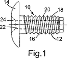
図1を参照すると、締結具10は、ほぼ円筒形の細長い軸部12と、一端(軸部の頭部端)に半径方向に拡大した頭部14を有する。軸部の一部16の外表面は、ねじ山18が形成されている。ねじ山18は、断面がV字形であり、ある角度(本実施形態では90°)でそのフランク(flank)が当合する頂き20が設けられている。ねじ山の隣接ターン(turn)間で、そのフランクは、ほぼV字形の谷を形成している。
Referring to FIG. 1, the
締結具は、軸部および頭部を通る軸孔22を有し、軸孔は直径がほぼ一定であるが、皿穴24を頭部端に有する。
The fastener has a
締結具は、炭素鋼からなり、例えばアルミニウム、マグネシウム、および締結具を取り付けることが望まれる被加工物を形成し得る広範のエンジニアリングプラスチック材料よりも硬い。 Fasteners are made of carbon steel and are harder than a wide range of engineering plastic materials that can form, for example, aluminum, magnesium, and workpieces to which it is desired to be attached.
締結具の材料は、軸部がある程度まで半径方向に拡張して変形するのに十分な延性があり、拡張後の軸部の主要直径(すなわち、ねじ山の頂きにおいて測られる直径)が、拡張する前よりも少なくともねじ山の深さだけ大きくなるようになっている。 The fastener material is ductile enough to allow the shaft to expand to some extent in the radial direction and deform, and the expanded main shaft diameter (ie, the diameter measured at the top of the thread) is expanded. It is designed to be at least as deep as the thread.
図2を参照すると、締結具10は、マンドレル26、環状アンビル28、およびアンビルに対し軸方向にマンドレルを把持するおよび引き抜く手段(図示せず)を備える装置によって取り付けられる。
Referring to FIG. 2, the
マンドレル26は、締結具の孔内のクリアランスを通過することができる細長いステム30、およびステムの一端に拡大ヘッド32を有する。このマンドレルヘッド32は、マンドレルの直径がステム30から遠ざかるにつれ締結具の孔22の直径よりも実質的に大きな直径へ漸進的に増加する円錐テーパ部分34を有する。また、マンドレルヘッド32は、マンドレルの断面形状が図示のように円形、または正六角形であってもよいヘッドを有する、幾分細長い部分36へとつながる。マンドレルは、高張力鋼から形成される。
The
環状アンビル28は、マンドレルのステムが把持および引き抜き手段と係合するように中を通ることができる軸路38、およびその前方端に当接面40を有する。図2ないし図11に示す実施形態では、当接面は平坦である。図12ないし図15に示す実施形態では、当接面はほぼ部分球形の中央リセス42を有する。アンビルは、その軸の長手方向に分割され、互いに同一であり共に協働して全アンビルを形成するほぼ2つの半環顎部44、46からなっている。顎部は、アンビルの軸部の直径方向に分離可能であり、締結具または一連の締結具が、分離した顎部内を通って、マンドレルのステムに沿ってマンドレルヘッド32に向かって前方に送り込まれるようにすることができ、その後、顎部は再び協働して当接面40を呈するよう締結具または各締結具の後ろで閉じ合わさることができる。
The
上記装置は、リベット打ちを繰り返す際に用いられるのとほぼ同様にして締結具を取り付けるのに用いることができる。 The device can be used to attach fasteners in much the same way that it is used when repeatedly riveting.
したがって、締結具10は、マンドレルのステムに沿って送り込まれ、そのステムは孔22内に延び、マンドレルヘッド32は締結具の尾端付近にあるが孔の外側にあり、マンドレルのステムは、引き抜き手段と係合するようにアンビルの通路38内を通って、締結具がマンドレルヘッドとアンビルの当接面40との間にあるようにする。
Thus, the
複数のさらなる締結具(図示せず)を、一度に1つずつ顎部を介してマンドレルヘッドとアンビルの当接面との間の定位置に送り込まれる態勢が整った状態で、同時にアンビルの後ろのステムに配置してもよい。 Several additional fasteners (not shown) are ready to be fed one position at a time between the mandrel head and the anvil abutment surface, one at a time, at the back of the anvil at the same time It may be arranged on the stem.
したがって、取り付け装置と連係した締結具10が、被加工物に提供され、アンビルが締結具の頭部を押して部材48の近接面と係合させ、次に、部材48を付勢して被加工物の近接面と当接させるまで、マンドレルヘッドおよび締結具の尾部は、部材48の開口部50を通って、被加工物52の開口部54に進入する。次に、取り付け装置は、締結具からマンドレルを引き抜くように作動し、そのため、マンドレルのヘッドを締結具の尾端内に、そして孔内に引き入れるとともに、締結具の頭部がアンビルの当接面により支持される。
Accordingly, a
マンドレルヘッドのテーパ部分34は、円筒部分36を締結具の孔に導き、そうすることで、軸部が尾端から頭部へ漸進的に拡張することを理解されたい。軸部の拡張が締結具の頭部の方に進むにつれ、軸部の漸進的に拡張する部分の前縁で雄ねじ山16の頂き20が被加工物52の材料とまず係合し、材料に陥入し始める時がやってくる。この時点で、係合したねじ山の軸方向位置が概ね固定される。
It should be understood that the
被加工物材料へのねじ山の食い込み(penetration)程度は、締結具の拡張された直径および被加工物の開口部54の直径(d1)に基づき、締結具の拡張された直径は、締結具の孔22の直径(d2)、締結具の軸部の最初の直径(d3)、およびマンドレルヘッドの円筒部分36の直径(d4)に基づくことを理解されたい。直径d1、d2、d3、およびd4は、被加工物へのねじ山の食い込みの程度がねじ山18の全高の半分以下となるように選択される。したがって、図3を参照すると、拡張したねじ山のV字形谷の根元58にスペース56が残っている。寸法(dimension)d1、d2、d3、およびd4は、根元58が完全にまたはほぼ完全に被加工物材料で埋まるようなものである場合、結果として、締結具材内の拡張地点に非常に高い半径方向圧力が必要とされることになる。これは、2つの望ましくない影響を有する。第1に、マンドレルに作用する軸方向引抜き荷重がそれに対応して高くなり、このため、マンドレルのステム30が過剰に応力をかけられる可能性がある。第2に、取り付けの際、締結具の軸部を延伸させる可能性がある。そのため、部材48は、取り付けられた締結具により被加工物52にしっかり締着されることができない。
The degree of penetration of the thread into the workpiece material is based on the expanded diameter of the fastener and the diameter (d 1 ) of the workpiece opening 54, and the expanded diameter of the fastener is It should be understood that this is based on the diameter (d 2 ) of the
寸法d1およびd3、ならびにマンドレルヘッドの円錐テーパ部分34の角度は、締結具の軸部の漸進的に拡張する部分がまず被加工物の材料と係合し、よって、概ね軸方向に固定されてからマンドレルの軸方向引抜き荷重が締結具を軸方向に圧縮するのに十分な大きさに達するように選択される。
The dimensions d 1 and d 3 and the angle of the
部材48の開口部50は、締結具がいかなる実質的な半径方向の制約もない状態で開口部内で拡張することができる程度に十分に大きい。したがって、部材内の拡張したねじ山部分60の直径は、図4に寸法「X」で示すように、被加工物内のねじ山部分62の直径よりもわずかに大きい。開口部50内のこのような制約されない拡張の効果は、部材内に入っている締結具軸部の部分の長さを軸方向に短くさせることである。例えば、鋼製の締結具の長さが少しだけ短くなっても、高い引張応力が得られ、これは、締結具の頭部と被加工物の間に高いクランプ力をもたらすことが理解されるであろう。ねじ山をすり減らす(strip)ことなく、このクランプ力を支持するのに十分な被加工物への拡張したねじ山の食い込みを与え、かつ取り付けられた締結具に、その作動中に常に引張力が加えられるように、寸法d1、d2、d3、およびd4を選択することが必要である。
The opening 50 of
実験により、本例の、以下の寸法で製造される締結具が、5.42mm穴径(d1)を有する鋳造マグネシウムの被加工物に取り付けられたときに意図したように機能することが分かっており、そのような被加工物に対し4mm厚、および6.3mm直径穴を有する鋼部材が、直径3.5mm(d4)のマンドレルを用いて締結具によって取着される。締結具の寸法は、孔22の直径が2.76mm(d2)、軸部の直径(ねじ山の頂きにおける直径)が5.3mm(d3)、軸部の長さが16mm、ねじ山のピッチが1.0mmである。このような場合、ねじ山の深さの30%〜40%の間の長さ分が被加工物へ拡張する。これは、作動中の締結具に作用するいかなる引張荷重も支持するのに十分な程度よりも大きい。実際に、この程度のねじ山の食い込みでの被加工物における締結具の保持力は、取り付けられた締結具に過剰な引張荷重が加えられたときに、ねじ山をすり減らすのではなく締結具を破損させるのに十分である。また、例えば、取り付けられた締結具に締付けトルクが加えられる場合、例えば、同等の六角形ヘッドマンドレルが用いられ、六角形レンチが用いられる場合では、ねじ山をすり減らすトルクは、同等のねじまたはボルト(この場合ではM6押しねじ、グレード8.8)の推奨最大締付けトルクを十分に超える。
Experiments have shown that the fasteners manufactured in this example with the following dimensions function as intended when attached to a cast magnesium workpiece having a 5.42 mm hole diameter (d 1 ). A steel member having a 4 mm thickness and a 6.3 mm diameter hole for such a workpiece is attached by means of a fastener using a mandrel with a diameter of 3.5 mm (d 4 ). The dimensions of the fastener are as follows: the diameter of the
当然のことながら、ねじ山すり減らしトルクおよび引き抜き引張荷重は、被加工物に係合する締結具の軸部の量(すなわち長さ)の程度によって決まり、この程度は、被加工物に取着される部材(単数または複数)の厚みによって決まることが理解される。軸部の少なくとも半分の長さが被加工物に係合する場合、上述の取り付けられた締結具の強度特性が維持される、すなわち本例では8mmに維持されることが分かっている。 Of course, the thread wear-off torque and the pull-out tensile load are determined by the degree of the amount (ie length) of the fastener shaft that engages the work piece, which is attached to the work piece. It is understood that it depends on the thickness of the member (s) to be determined. It has been found that when at least half the length of the shank engages the workpiece, the strength characteristics of the attached fastener described above are maintained, i.e., 8 mm in this example.
部材48が非常に薄い場合、すなわち上記例では1.5mm未満の場合、締結具の頭部付近のねじ山位置が半径方向の制約なしに拡張したときに生じるクランプ作用を得るために、被加工物の開口部54のカウンタボアを生成することが必要となる場合がある。示した例と同じ構成の締結具、および厚さが例えば1mmの部材では、カウンタボアの深さは2mmで十分である。
If the
図4を参照すると、被加工物内に嵌め込まれた締結具の部分のねじ山ピッチ64は、概ね変わらないままである、すなわち、示した例では1.0mmのままである。しかしながら、部材48内に嵌め込まれた締結具の部分のねじ山ピッチ66は、示した例では0.94mmに減少している。この作用は、図5に示すグラフに示される。
Referring to FIG. 4, the
ある用途では、締結具を受容する開口部が鋳造作業によって形成される被加工物に締結具を使用することが好ましい。この場合、開口部は、好ましくはテーパ(またはドラフト)を有し、ドラフトの角度は通常、1°〜1.5°(1°と1.5°も含む)である。本発明の締結具は、このようなテーパ状の穴において申し分なく機能する。図6および対応する図7のねじ山ピッチのグラフを参照すると、被加工物の開口部68は、例示目的のために誇張したテーパを有して示されている。締結具および開口部の直径は、最小厚の部材の場合、締結具を阻害せずに穴に完全に挿入することができるように(そうでなければ、部材と被加工物の上面の間および/または部材の上面と締結具の間に間隙があるはずである)選択される。
For some applications, it is preferred to use the fastener on a workpiece in which an opening for receiving the fastener is formed by a casting operation. In this case, the opening preferably has a taper (or draft), and the draft angle is usually 1 ° to 1.5 ° (including 1 ° and 1.5 °). The fastener of the present invention functions satisfactorily in such a tapered hole. Referring to FIG. 6 and the corresponding thread pitch graph of FIG. 7, the
図6は、取り付け前の締結具が部材の開口部を通って被加工物の開口部68に挿入されたときに、部材と被加工物の間または部材と締結具の頭部の間に間隙を有さずに、軸部の遠位端が開口部68のテーパ状壁とただ接触している極端な例の場合の取り付けられた締結具を示す。この場合、軸部の部分72での拡張したねじ山の食い込みの深さがねじ山深さの50%を上回る可能性があり、締結具がこの領域で拡張したときに締結具の過度の半径方向の制約が生じるため、この領域において軸部の延伸の可能性がある。1°のテーパを有する被加工物開口部に取り付けられた締結具の例では、拡張した締結具のねじ山ピッチは、部分72では1.03mmとすることができる。しかしながら、開口部が被加工物の上面に向かって漸進的に拡大するにつれて、半径方向の制約はそれに対応して低減し、ねじ山の食い込みの深さは、ねじ山の深さの半分未満に減る可能性がある。全体の作用は、取り付けられた締結具の長さが短くなり、したがって部材上に所要のクランプ力をもたらすことである。
FIG. 6 illustrates the gap between the member and the workpiece or between the member and the head of the fastener when the fastener before attachment is inserted into the workpiece opening 68 through the opening in the member. In the extreme case where the distal end of the shank is just in contact with the tapered wall of the
被加工物に取着すべき部材が弾性材のような非剛性部材から製造される用途では、取り付けプロセスの際に起こる締結具の長さの短縮は、図8〜図11に示すように部材を圧縮する作用を有する。先の場合のように、締結具は、部材の開口部を通って、先に説明したのと同様にして被加工物の開口部に進入する。この場合、部材74(図8)は弾性材である。取り付け装置によってマンドレルヘッドがリベット孔内に引き入れられると、図9に示すように、軸部の漸進的に拡張した部分の前端がまず被加工物の材料と係合し、その被加工物の材料に陥入し始め、前述したように、係合したねじ山76(図9)が概ね固定される。取り付け装置によりマンドレルステムに加えられる軸方向引き力が増すと、締結具の頭部および係合したねじ山76の間の締結具軸部の部分78の圧縮力も増す。力がさらに増すと、軸部78(図10)が、残りのねじ山80(図10)が被加工物の開口部との接触および弾性部材の変形に対する抗力により拡張を制約されるまで可塑的に圧縮する。力がさらに増すと、マンドレルヘッドは、締結具の孔から完全に引き抜かれ、これによる作用は、先に説明したのと同様にして締結具軸部をさらに短くさせることである。これにより、部材74(図11)に作用するクランプ荷重が増大し、部材が後続してさらに圧縮される。
In applications where the member to be attached to the workpiece is manufactured from a non-rigid member, such as an elastic material, the shortening of the fastener length that occurs during the attachment process is as shown in FIGS. Has the action of compressing. As in the previous case, the fastener passes through the opening in the member and enters the opening in the workpiece in the same manner as previously described. In this case, the member 74 (FIG. 8) is an elastic material. When the mandrel head is pulled into the rivet hole by the mounting device, the front end of the progressively expanded portion of the shaft portion first engages the material of the workpiece, as shown in FIG. The engaged thread 76 (FIG. 9) is generally fixed as described above. As the axial pulling force applied to the mandrel stem by the mounting device increases, the compressive force of the
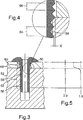
用途によっては、部材と被加工物の間に間隙が存在する可能性があり、この間隙は、作業者が部材と被加工物に締結具を係合させる際に行う通常の押し込み作用では詰めることはできないことが実際に分かっている。間隙が小さい場合、本発明によるリベットにおけるリベット軸部の短縮作用が、間隙を詰め、部材にクランプ力を生じさせるのに十分である可能性がある。部材と被加工物の間により大きな間隙が存在し得る用途では、上述したリベットは、本発明に従って、締結具の頭部が当接する面にリセス42を有するアンビル82(図12)とともに用いることができる。リセス42の幾何形状および深さは、第1に、締結具頭部84(図15)の最終的に変形した形状の外観が仕上げの点から許容可能であるように、第2に、締結具の取り付けに起因する頭部の変形の程度が頭部の保護コーティングを損傷させるほど大きくないように、第3に、軸部に対する締結具頭部の周辺の軸方向移動が、被加工物に向かって部材を移動させ、かつ所定の間隙を詰めるのに十分であるように構成される。本発明の実施形態を次に、図12〜図15を参照して詳細に説明する。
Depending on the application, there may be a gap between the member and the workpiece, and this gap is filled by the normal push-in action performed by the operator when the fastener is engaged with the member and the workpiece. I know I can't. If the gap is small, the shortening action of the rivet shaft in the rivet according to the invention may be sufficient to close the gap and create a clamping force on the member. In applications where a larger gap may exist between the member and the workpiece, the rivet described above may be used with an anvil 82 (FIG. 12) having a
図12を参照すると、先の場合でのように、締結具は、アンビルが締結具の頭部を押して部材48の近接面と係合するまで、部材48の開口部50を通って、被加工物52の開口部54に進入する。この場合では、部材と被加工物の間に間隙86がある。次に、取り付け装置が、締結具からマンドレルを引き抜くように作動し、そのため、マンドレルのヘッド32が孔内に引き入れられるとともに、締結具の頭部がアンビルの当接面88によって支持される。取り付けプロセスの初期の段階において、図12および図13に示すように、アンビルの当接面88は、その周辺付近の締結具頭部と接触する。この状態は、マンドレルヘッドが軸部の端部でねじ山部分90(図13)を拡張させて被加工物と係合するようにまでそのままであるため、被加工物に対し軸部の端部が軸方向に固定される。さらなる引き荷重をマンドレルに加えると、ねじ山のより大きな部分92(図14)が拡張して被加工物と係合する。アンビル82と締結具の頭部の間の反力が、頭部の周縁が被加工物側に変形するように頭部を十分に変形させることで、部材48を被加工物52に向かって移動させて被加工物52と接触させるため、部材と被加工物の間に存在する可能性があるいかなる間隙もなくなる。締結具の頭部を変形させる荷重は、所与の締結具材および冶金条件の場合、締結具の頭部およびアンビルリセスの幾何学形状の慎重な選択により管理され、頭部は、係合したねじ山部分90(図13)を形成する必要があるよりも大きく、かつ締結具の孔から完全にマンドレルヘッドを引き抜くのに要される最大引き荷重よりも小さいマンドレル引き荷重で必要なだけ変形するようになっている。先の例におけるように、部材48の開口部50(図15)内に嵌め込んだ拡張した締結具軸部の部分は、被加工物中で拡張する軸部の部分の半径方向の制約を有さない。先の例におけるように、開口部50のこの非制約拡張の作用は、部材内に嵌め込まれる締結具の部分の長さを軸方向に短くさせることであり、その結果、締結部の頭部と被加工物の間にクランプ力が生じる。部材が被加工物に締結されることが必要とされる多くの用途では、種々の位置で複数の締結具が用いられることが理解されよう。これらの位置によっては、特定の部材および被加工物に応じて、86(図12)に示すように部材と被加工物の間に間隙がある可能性があり、位置によっては、間隙が存在しない。かかる用途では、間隙があるか否かにかかわらず、各位置で同一の締結具および同じタイプの取り付け装置を用いることが望ましいことは明らかである。本実施形態の締結具および取り付け装置は、部材と被加工物の間に間隙がない場合、申し分なく機能するであろう。この場合、締結具軸部の第1のいくつかのねじ山が被加工物と係合すると(図13に対応)、軸の端部を被加工物に軸方向へ固定し、さらなる引き荷重がマンドレルに加えられると、締結具頭部のアンビルの反力負荷が頭部を付勢して変形させる。しかしながら、部材と被加工物の間に間隙がなく、部材が比較的硬い材料、例えばアルミニウム、または炭素繊維複合物、または鋼から製造される場合、締結具の頭部の周縁は、被加工物側に変形することを防止され、頭部の形状は、締結具の取り付け前と取り付け後とで概ね変わらない。部材48がプラスチック材料、たとえばナイロン、またはポリウレタンから製造されている場合、頭部の周縁は、アンビルに作用する反応力と部材の変形を抗する力の影響下で、ある程度変形することが理解されるであろう。この場合、締結具頭部は、図15に示す程度ほど変形することはないが、図12と図15に示した程度の中間程度に変形する。部材48が非常に軟質の材料、例えばゴムまたはプラスチック発泡体から製造される場合、変形に対し耐性が低く、取り付けられた締結具は、図14および図15に示すような頭部形状、すなわち、アンビルのリセス42(図12)の幾何形状よって完全に決まる形状を有する。
Referring to FIG. 12, as in the previous case, the fastener is processed through the
上述の実施形態は、締結具軸部の端部の下側に延在する被加工物の止り穴(blind hole:盲穴)に取り付けられた例の締結具を示す。このことは、被加工物の穴が貫通していても、また、締結具のねじ山軸部の部分が締結具のヘッドから離れて被加工物の端面を超えて突出するとしても、締結具は本発明に従って機能するため、必要不可欠ではない。 The above-described embodiments show an example fastener attached to a blind hole in a workpiece that extends below the end of the fastener shaft. This means that even if the hole in the work piece penetrates, or even if the threaded shaft portion of the fastener is separated from the head of the fastener and protrudes beyond the end face of the work piece, Is not essential since it functions in accordance with the present invention.
例において、マンドレルヘッドは、円形断面を有するものとして示されている。複数のレンチ面を提供するために多角形のヘッド断面形状を有するとともに、軸部を半径方向に均等に拡張できる延性を提供するマンドレルを用いることができることが理解されよう。 In the example, the mandrel head is shown as having a circular cross section. It will be appreciated that a mandrel having a polygonal head cross-sectional shape to provide a plurality of wrench surfaces and providing ductility that allows the shaft portion to expand radially can be used.
上記の例は、リベットの頭部を著しく変形させる必要なく、取り付けられたリベットのリベット頭部の幾何学形状が最初に製造された形と概ね変わらないように、接合した部材に高いクランプ力を生じさせる締結方法を提供することを含む。 The above example provides a high clamping force on the joined members so that the rivet head geometry of the attached rivet is not substantially different from the originally manufactured shape without requiring significant deformation of the rivet head. Providing the resulting fastening method.
軸部が半径方向に拡張すると同時に長さを軸方向に短くして、例えばリベットにより被加工物に接合される非剛性部材の圧縮をもたらす締結方法も提供される。 A fastening method is also provided in which the shaft expands in the radial direction and at the same time shortens the length in the axial direction, resulting in compression of the non-rigid member joined to the workpiece, for example by rivets.
リベットおよびその取り付け工具が、リベットの取り付けの際に、リベットの頭部が、接合された部材と被加工物の間に存在する可能性があるいかなる間隙も詰めるのに効果的な、リベットの尾端側に向って変形するように構成される締結方法も提供される。 The rivet tail, which is effective for the rivet and its installation tool to pack any gaps that the rivet head may exist between the joined member and the workpiece during rivet installation. A fastening method is also provided that is configured to deform toward the end side.
締結具を取り付けるべき被加工物は、リベットの材料よりも硬くない材料からなるべきであることが分かるであろう。リベットは、アルミニウムおよびマグネシウムなどの軟金属、ならびにプラスチックでの使用を意図されている。 It will be appreciated that the work piece to which the fastener is to be attached should be made of a material that is not harder than the material of the rivet. Rivets are intended for use with soft metals such as aluminum and magnesium, and plastics.
被加工物は、リベットの軸部を、好ましくは軸部の周縁が最小のクリアランスで挿入することができる開口部を有するものとする。開口部は、均一な直径を有するか、またはアルミニウムまたはマグネシウム鋳造での鋳造により形成された穴に典型的な傾斜の小さいテーパを有することができる止り穴であるべきである。 The workpiece has an opening through which the shaft portion of the rivet can be inserted, preferably with a minimum clearance at the periphery of the shaft portion. The opening should be a blind hole that can have a uniform diameter or have a small slope taper typical of holes formed by casting in aluminum or magnesium casting.
リベットにより被加工物に取着される部材は、リベットの拡張直径よりも直径が大きい開口部を有するものとする。 The member attached to the workpiece by the rivet shall have an opening having a diameter larger than the expanded diameter of the rivet.
本発明は、上記の例の詳細に限定されない。たとえば、用いられる締結具の孔は、その長さに沿って寸法が均一である必要はない。 The present invention is not limited to the details of the above examples. For example, the fastener holes used need not be uniform in size along their length.
Claims (8)
少なくとも1つの前記有孔部材の開口部は、前記有孔被加工物の開口部と位置合わせされ、
前記方法は、
位置合わせされた少なくとも1つの前記有孔部材の前記開口部と、前記有孔被加工物の前記開口部とに締結具を挿入するステップであって、
前記締結具は延性材料からなり、頭部、軸部、および前記軸部を通って前記頭部に延びている軸孔を有し、前記軸部には、円周方向全体に雄ねじ山が切られ、
前記締結具の前記頭部が、対向する前記有孔部材の面と係合し、
前記締結具の前記軸部が、少なくとも1つの前記有孔部材の前記開口部内を通って、前記有孔被加工物の前記開口部内に延び、
前記軸部の前記雄ねじ山の少なくとも一部が、前記有孔被加工物の前記開口部内にあるように、前記締結具を挿入するステップと、
前記頭部で前記締結具を支持するとともに、
円筒部分を一端側に含む、テーパ状に拡大したマンドレルヘッドであって、前記円筒部分は、前記締結具の前記軸孔より大きい直径を有し、前記マンドレルヘッドと、前記締結具の前記頭部での前記支持との間で、前記締結具の前記軸部を軸方向に圧縮でき、かつ、前記軸孔を拡張できるマンドレルヘッドを、
前記締結具の尾部から前記頭部の方向に、前記軸孔内に引き入れ、かつ、前記軸孔から完全に引き抜くステップと
を含み、
それにより、前記軸孔の長さにわたって均一に前記軸孔を拡大させ、かつ、前記雄ねじ山が、前記有孔被加工物の前記開口部内に陥入するのに十分なだけ前記軸部を半径方向に可塑的に拡張させ、前記締結具の前記軸部の長さを軸方向に可塑的に短縮させ、
前記有孔被加工物の前記開口部の直径、拡大される前における前記締結具の前記軸孔の直径、前記締結具の前記軸部の直径、及び前記マンドレルヘッドの前記円筒部分の直径は、前記被加工物への、前記雄ねじ山の食い込みの程度が、前記雄ねじ山の全高の半分以下となるように選択される、有孔被加工物に1つまたは複数の有孔部材を締結する方法。A method for fastening one or more perforated members to a perforated workpiece,
At least one aperture of the perforated member is aligned with an aperture of the perforated workpiece;
The method
Inserting a fastener into the aligned at least one aperture of the perforated member and the aperture of the perforated workpiece;
The fastener is made of a ductile material, and has a head portion, a shaft portion, and a shaft hole extending through the shaft portion to the head portion. The shaft portion has a male thread cut in the entire circumferential direction. And
The head of the fastener engages the surface of the perforated member facing;
The shaft of the fastener extends through the opening of at least one of the perforated members and into the opening of the perforated workpiece;
Inserting the fastener such that at least a portion of the male thread of the shaft is within the opening of the perforated workpiece;
While supporting the fastener with the head,
A mandrel head expanded in a tapered shape including a cylindrical portion on one end side , wherein the cylindrical portion has a diameter larger than the shaft hole of the fastener, and the mandrel head and the head of the fastener A mandrel head capable of axially compressing the shaft portion of the fastener and expanding the shaft hole between the support and
Pulling into the shaft hole in the direction of the head from the tail of the fastener, and completely pulling out from the shaft hole,
Thereby, the shaft hole is enlarged uniformly over the length of the shaft hole, and the shaft thread has a radius sufficient for the male thread to be recessed into the opening of the perforated workpiece. Plastically expanded in the direction, the length of the shaft portion of the fastener is plastically shortened in the axial direction ,
The diameter of the opening of the perforated workpiece, the diameter of the shaft hole of the fastener before being expanded, the diameter of the shaft portion of the fastener, and the diameter of the cylindrical portion of the mandrel head are: A method of fastening one or more perforated members to a perforated workpiece , wherein the degree of biting of the male thread into the workpiece is selected to be less than half of the total height of the male thread .
少なくとも1つの前記有孔部材の開口部は、前記有孔被加工物の開口部と位置合わせされ、
前記方法は、
位置合わせされた少なくとも1つの前記有孔部材の前記開口部と、前記有孔被加工物の前記開口部とに締結具を挿入するステップであって、
前記締結具は延性材料からなり、頭部、軸部、および前記軸部を通って前記頭部に延びている軸孔を有し、前記軸部には、円周方向全体に雄ねじ山が切られ、
前記締結具の前記頭部が、対向する前記有孔部材の面と係合し、
前記締結具の前記軸部が、少なくとも1つの前記有孔部材の前記開口部内を通って、前記有孔被加工物の前記開口部内に延び、
前記軸部の前記雄ねじ山の少なくとも一部が、前記有孔被加工物の前記開口部内にあるように、前記締結具を挿入するステップと、
テーパ状に拡大したマンドレルヘッドであって、前記マンドレルヘッドと、前記締結具の前記頭部での前記支持との間で、前記締結具の前記軸部を軸方向に圧縮でき、かつ、前記軸孔を拡張できるマンドレルヘッドを、
前記締結具の尾部から前記頭部の方向に、前記軸孔内に引き入れ、かつ、前記軸孔から完全に引き抜くステップと
を含み、
前記締結具の前記頭部の周縁部が、
前記軸部の前記雄ねじ山を、前記有孔被加工物の前記開口部内に陥入させる荷重よりも大きく、かつ、前記締結具の前記軸孔から、前記マンドレルヘッドを完全に引き抜くのに要する荷重よりも小さい荷重によって変形する、有孔被加工物に少なくとも1つの有孔部材を締結する方法。A method for fastening at least one perforated member to a perforated workpiece,
At least one aperture of the perforated member is aligned with an aperture of the perforated workpiece;
The method
Inserting a fastener into the aligned at least one aperture of the perforated member and the aperture of the perforated workpiece;
The fastener is made of a ductile material, and has a head portion, a shaft portion, and a shaft hole extending through the shaft portion to the head portion. The shaft portion has a male thread cut in the entire circumferential direction. And
The head of the fastener engages the surface of the perforated member facing;
The shaft of the fastener extends through the opening of at least one of the perforated members and into the opening of the perforated workpiece;
Inserting the fastener such that at least a portion of the male thread of the shaft is within the opening of the perforated workpiece;
A mandrel head enlarged in a taper shape, the shaft portion of the fastener being axially compressible between the mandrel head and the support at the head of the fastener, and the shaft A mandrel head that can expand the hole,
Pulling into the shaft hole in the direction of the head from the tail of the fastener, and completely pulling out from the shaft hole,
The peripheral edge of the head of the fastener is
The load required to completely pull out the mandrel head from the shaft hole of the fastener is larger than the load causing the male thread of the shaft portion to be recessed into the opening of the perforated workpiece. A method of fastening at least one perforated member to a perforated workpiece that is deformed by a smaller load.
前記有孔被加工物と、前記少なくとも1つの有孔部材との間に隙間がある場合、
および/または、
前記締結具の前記頭部に係合している前記有孔部材が、軟質な材料から製造されている場合、
前記締結具の前記頭部の周縁部が、前記締結具の前記尾部の方向に移動するように変形し、
前記頭部の前記周縁部の前記変形により、
前記有孔被加工物と、前記少なくとも1つの有孔部材との間の隙間を詰め、
および/または、
前記有孔部材を変形させ、それによって、前記締結具の前記頭部と前記有孔被加工物との間で、前記有孔部材をしっかり締着する、請求項1に記載の締結する方法。After the male thread has invaginated in the opening of the perforated workpiece,
If there is a gap between the perforated workpiece and the at least one perforated member,
And / or
When the perforated member engaged with the head of the fastener is manufactured from a soft material,
The peripheral portion of the head of the fastener is deformed to move in the direction of the tail of the fastener;
By the deformation of the peripheral edge of the head,
Filling a gap between the perforated workpiece and the at least one perforated member;
And / or
The fastening method according to claim 1, wherein the perforated member is deformed, thereby firmly fastening the perforated member between the head of the fastener and the perforated workpiece.
Applications Claiming Priority (2)
| Application Number | Priority Date | Filing Date | Title |
|---|---|---|---|
| GB0129878A GB2383106B (en) | 2001-12-14 | 2001-12-14 | Method of fastening |
| PCT/GB2002/005661 WO2003051557A1 (en) | 2001-12-14 | 2002-12-13 | Method of fastening |
Publications (3)
| Publication Number | Publication Date |
|---|---|
| JP2005511319A JP2005511319A (en) | 2005-04-28 |
| JP2005511319A5 JP2005511319A5 (en) | 2006-01-05 |
| JP4133826B2 true JP4133826B2 (en) | 2008-08-13 |
Family
ID=9927585
Family Applications (1)
| Application Number | Title | Priority Date | Filing Date |
|---|---|---|---|
| JP2003552472A Expired - Lifetime JP4133826B2 (en) | 2001-12-14 | 2002-12-13 | Fastening method |
Country Status (15)
| Country | Link |
|---|---|
| US (1) | US7503106B2 (en) |
| EP (1) | EP1455970B1 (en) |
| JP (1) | JP4133826B2 (en) |
| KR (1) | KR20040072656A (en) |
| CN (1) | CN1291805C (en) |
| AT (1) | ATE490039T1 (en) |
| AU (1) | AU2002350958B2 (en) |
| CA (1) | CA2470005C (en) |
| DE (1) | DE60238505D1 (en) |
| ES (1) | ES2355134T3 (en) |
| GB (1) | GB2383106B (en) |
| MX (1) | MXPA04005752A (en) |
| TW (1) | TWI221886B (en) |
| WO (1) | WO2003051557A1 (en) |
| ZA (1) | ZA200404725B (en) |
Families Citing this family (22)
| Publication number | Priority date | Publication date | Assignee | Title |
|---|---|---|---|---|
| FR2874890B1 (en) * | 2004-09-03 | 2006-12-29 | Faurecia Interieur Ind Snc | DASHBOARD ARRANGEMENT SUITABLE FOR SIMPLIFIED ASSEMBLY OF AN AIRBAG SAFETY MODULE, AND METHOD OF MAKING SUCH ARRANGEMENT |
| CN102255417B (en) * | 2007-02-19 | 2015-09-02 | 株式会社美姿把 | Holder stay fixing structure and motor with brush |
| CN101909548B (en) | 2008-01-17 | 2014-07-30 | 斯恩蒂斯有限公司 | An expandable intervertebral implant and associated method of manufacturing the same |
| CN102036623A (en) | 2008-04-05 | 2011-04-27 | 斯恩蒂斯有限公司 | Expandable intervertebral implant |
| GB2463043B (en) * | 2008-08-29 | 2013-01-30 | Avdel Uk Ltd | Blind fastener |
| CA2711259C (en) * | 2009-01-06 | 2013-10-29 | Alcoa Inc. | Advanced nut and bolt |
| CA2767403C (en) | 2009-07-06 | 2017-08-29 | Synthes Usa, Llc | Expandable fixation assemblies |
| US8979860B2 (en) | 2010-06-24 | 2015-03-17 | DePuy Synthes Products. LLC | Enhanced cage insertion device |
| CN103317078B (en) * | 2013-07-11 | 2015-06-03 | 株洲时代金属制造有限公司 | Rivet pulling mechanism and rivet pulling method |
| CN104214191A (en) * | 2013-10-28 | 2014-12-17 | 襄阳顺应机械有限责任公司 | Displacement friction internal expansion lock bolt |
| US10655669B2 (en) | 2013-11-26 | 2020-05-19 | Arconic Inc. | Advanced nut and bolt |
| EP3074647B1 (en) | 2013-11-26 | 2019-10-09 | Arconic Inc. | Advanced nut and bolt |
| CN103752754B (en) * | 2014-02-24 | 2015-08-12 | 上海英汇科技发展有限公司 | A kind of staking fastening method and instrument |
| DE102014002951A1 (en) * | 2014-03-06 | 2015-09-10 | Nela Gmbh | Device for smoothing |
| DE102015009044A1 (en) * | 2015-07-13 | 2017-01-19 | Sfs Intec Holding Ag | Process for the preparation of a compound |
| JP6345222B2 (en) * | 2016-11-25 | 2018-06-20 | 日本特殊陶業株式会社 | Metal fittings, rolling dies, male thread forming method |
| US10377508B2 (en) * | 2016-11-29 | 2019-08-13 | The Boeing Company | Enhanced tooling for interference-fit fasteners |
| US10888433B2 (en) | 2016-12-14 | 2021-01-12 | DePuy Synthes Products, Inc. | Intervertebral implant inserter and related methods |
| US10675671B2 (en) * | 2017-01-30 | 2020-06-09 | GM Global Technology Operations LLC | Blind flow screw joining of materials |
| US10940016B2 (en) | 2017-07-05 | 2021-03-09 | Medos International Sarl | Expandable intervertebral fusion cage |
| US11692545B2 (en) * | 2018-08-20 | 2023-07-04 | Spm Oil & Gas Inc. | Suction cover assembly for reciprocating pumps |
| EP4319669A1 (en) * | 2021-04-06 | 2024-02-14 | Acumed LLC | Surgical bone rivet |
Family Cites Families (8)
| Publication number | Priority date | Publication date | Assignee | Title |
|---|---|---|---|---|
| GB640451A (en) | 1946-09-02 | 1950-07-19 | Aviat Developments Ltd | Improvements in or relating to tubular fastening devices or bushes |
| AT189858B (en) * | 1947-10-02 | 1957-05-10 | Aviat Developments Ltd | Hollow rivet-like connector for connecting workpieces |
| US4488843A (en) * | 1982-07-16 | 1984-12-18 | Illinois Tool Works Inc. | Reusable one piece drive fastener |
| GB8315077D0 (en) * | 1983-06-01 | 1983-07-06 | Avdel Ltd | Threaded fastener |
| GB2140891B (en) * | 1983-06-01 | 1986-11-19 | Avdel Ltd | Swaged-in threaded fastener |
| GB9501849D0 (en) * | 1995-01-31 | 1995-03-22 | Avdel Systems Ltd | Method of fastening members of an assembly |
| DE19543651C2 (en) | 1995-11-23 | 1999-06-02 | Brose Fahrzeugteile | Expandable fastener for attaching or connecting parts |
| DE19646668A1 (en) | 1996-11-12 | 1998-05-14 | Sfs Ind Holding Ag | Fastener insertable in a blind hole |
-
2001
- 2001-12-14 GB GB0129878A patent/GB2383106B/en not_active Expired - Lifetime
-
2002
- 2002-12-13 EP EP02785670A patent/EP1455970B1/en not_active Expired - Lifetime
- 2002-12-13 WO PCT/GB2002/005661 patent/WO2003051557A1/en active Application Filing
- 2002-12-13 CA CA002470005A patent/CA2470005C/en not_active Expired - Lifetime
- 2002-12-13 CN CNB028279387A patent/CN1291805C/en not_active Expired - Lifetime
- 2002-12-13 JP JP2003552472A patent/JP4133826B2/en not_active Expired - Lifetime
- 2002-12-13 ES ES02785670T patent/ES2355134T3/en not_active Expired - Lifetime
- 2002-12-13 KR KR10-2004-7009205A patent/KR20040072656A/en active Search and Examination
- 2002-12-13 US US10/498,623 patent/US7503106B2/en not_active Expired - Fee Related
- 2002-12-13 TW TW091136148A patent/TWI221886B/en not_active IP Right Cessation
- 2002-12-13 DE DE60238505T patent/DE60238505D1/en not_active Expired - Lifetime
- 2002-12-13 MX MXPA04005752A patent/MXPA04005752A/en active IP Right Grant
- 2002-12-13 AT AT02785670T patent/ATE490039T1/en not_active IP Right Cessation
- 2002-12-13 AU AU2002350958A patent/AU2002350958B2/en not_active Ceased
-
2004
- 2004-06-15 ZA ZA2004/04725A patent/ZA200404725B/en unknown
Also Published As
| Publication number | Publication date |
|---|---|
| JP2005511319A (en) | 2005-04-28 |
| ES2355134T3 (en) | 2011-03-23 |
| CN1617777A (en) | 2005-05-18 |
| GB2383106B (en) | 2004-09-15 |
| EP1455970A1 (en) | 2004-09-15 |
| DE60238505D1 (en) | 2011-01-13 |
| AU2002350958A1 (en) | 2003-06-30 |
| WO2003051557A1 (en) | 2003-06-26 |
| KR20040072656A (en) | 2004-08-18 |
| CA2470005C (en) | 2008-07-29 |
| TW200307092A (en) | 2003-12-01 |
| AU2002350958B2 (en) | 2007-10-18 |
| GB0129878D0 (en) | 2002-02-06 |
| CA2470005A1 (en) | 2003-06-26 |
| TWI221886B (en) | 2004-10-11 |
| US7503106B2 (en) | 2009-03-17 |
| CN1291805C (en) | 2006-12-27 |
| ATE490039T1 (en) | 2010-12-15 |
| MXPA04005752A (en) | 2004-09-10 |
| US20050155212A1 (en) | 2005-07-21 |
| ZA200404725B (en) | 2005-04-26 |
| GB2383106A (en) | 2003-06-18 |
| EP1455970B1 (en) | 2010-12-01 |
Similar Documents
| Publication | Publication Date | Title |
|---|---|---|
| JP4133826B2 (en) | Fastening method | |
| US8118527B2 (en) | Pull stem fastener with pull groove for swaging collars | |
| US4142439A (en) | Blind fastener assembly | |
| US4642010A (en) | Threaded fastener and method of installing same | |
| US4969785A (en) | Fastener mandrel and method | |
| US4904133A (en) | Fastener with integral locking means | |
| US7677853B2 (en) | Multi-lobular lockbolt and system | |
| US7722303B2 (en) | Frangible blind rivet | |
| JP5193063B2 (en) | Blind rivets and equipment for blind rivets | |
| US20170218996A1 (en) | Fastening structure and fastening method | |
| US5171115A (en) | Swage collar with pintail and fastening system and method | |
| JP2005535843A (en) | Pull-type swage-type fastener with removable mandrel | |
| US8029220B2 (en) | Blind rivet assembly | |
| EP2597324B1 (en) | Rivet stud | |
| EP3009695B1 (en) | Deformable sleeve nut and a method of manufacturing | |
| KR0163594B1 (en) | Fastener system including a swage fastener and tool for installing the same | |
| JPH08509285A (en) | A trapezoid fixture with a two-piece extension | |
| US4977663A (en) | Method for securing workpieces of composite materials | |
| GB1604502A (en) | Blind fastener | |
| GB2140891A (en) | Swaged-in threaded fastener |
Legal Events
| Date | Code | Title | Description |
|---|---|---|---|
| A521 | Request for written amendment filed |
Free format text: JAPANESE INTERMEDIATE CODE: A523 Effective date: 20050606 |
|
| A621 | Written request for application examination |
Free format text: JAPANESE INTERMEDIATE CODE: A621 Effective date: 20050606 |
|
| A977 | Report on retrieval |
Free format text: JAPANESE INTERMEDIATE CODE: A971007 Effective date: 20070305 |
|
| A131 | Notification of reasons for refusal |
Free format text: JAPANESE INTERMEDIATE CODE: A131 Effective date: 20070313 |
|
| A601 | Written request for extension of time |
Free format text: JAPANESE INTERMEDIATE CODE: A601 Effective date: 20070613 |
|
| A521 | Request for written amendment filed |
Free format text: JAPANESE INTERMEDIATE CODE: A523 Effective date: 20070710 |
|
| A601 | Written request for extension of time |
Free format text: JAPANESE INTERMEDIATE CODE: A601 Effective date: 20070713 |
|
| A602 | Written permission of extension of time |
Free format text: JAPANESE INTERMEDIATE CODE: A602 Effective date: 20070620 |
|
| A602 | Written permission of extension of time |
Free format text: JAPANESE INTERMEDIATE CODE: A602 Effective date: 20070724 |
|
| A601 | Written request for extension of time |
Free format text: JAPANESE INTERMEDIATE CODE: A601 Effective date: 20070813 |
|
| A602 | Written permission of extension of time |
Free format text: JAPANESE INTERMEDIATE CODE: A602 Effective date: 20070820 |
|
| A521 | Request for written amendment filed |
Free format text: JAPANESE INTERMEDIATE CODE: A523 Effective date: 20070913 |
|
| A131 | Notification of reasons for refusal |
Free format text: JAPANESE INTERMEDIATE CODE: A131 Effective date: 20071009 |
|
| A601 | Written request for extension of time |
Free format text: JAPANESE INTERMEDIATE CODE: A601 Effective date: 20080109 |
|
| A602 | Written permission of extension of time |
Free format text: JAPANESE INTERMEDIATE CODE: A602 Effective date: 20080117 |
|
| A521 | Request for written amendment filed |
Free format text: JAPANESE INTERMEDIATE CODE: A523 Effective date: 20080206 |
|
| TRDD | Decision of grant or rejection written | ||
| A01 | Written decision to grant a patent or to grant a registration (utility model) |
Free format text: JAPANESE INTERMEDIATE CODE: A01 Effective date: 20080507 |
|
| A01 | Written decision to grant a patent or to grant a registration (utility model) |
Free format text: JAPANESE INTERMEDIATE CODE: A01 |
|
| A61 | First payment of annual fees (during grant procedure) |
Free format text: JAPANESE INTERMEDIATE CODE: A61 Effective date: 20080602 |
|
| FPAY | Renewal fee payment (event date is renewal date of database) |
Free format text: PAYMENT UNTIL: 20110606 Year of fee payment: 3 |
|
| R150 | Certificate of patent or registration of utility model |
Ref document number: 4133826 Country of ref document: JP Free format text: JAPANESE INTERMEDIATE CODE: R150 Free format text: JAPANESE INTERMEDIATE CODE: R150 |
|
| FPAY | Renewal fee payment (event date is renewal date of database) |
Free format text: PAYMENT UNTIL: 20120606 Year of fee payment: 4 |
|
| R250 | Receipt of annual fees |
Free format text: JAPANESE INTERMEDIATE CODE: R250 |
|
| FPAY | Renewal fee payment (event date is renewal date of database) |
Free format text: PAYMENT UNTIL: 20120606 Year of fee payment: 4 |
|
| FPAY | Renewal fee payment (event date is renewal date of database) |
Free format text: PAYMENT UNTIL: 20130606 Year of fee payment: 5 |
|
| R250 | Receipt of annual fees |
Free format text: JAPANESE INTERMEDIATE CODE: R250 |
|
| R250 | Receipt of annual fees |
Free format text: JAPANESE INTERMEDIATE CODE: R250 |
|
| R250 | Receipt of annual fees |
Free format text: JAPANESE INTERMEDIATE CODE: R250 |
|
| R250 | Receipt of annual fees |
Free format text: JAPANESE INTERMEDIATE CODE: R250 |
|
| R250 | Receipt of annual fees |
Free format text: JAPANESE INTERMEDIATE CODE: R250 |
|
| R250 | Receipt of annual fees |
Free format text: JAPANESE INTERMEDIATE CODE: R250 |
|
| R250 | Receipt of annual fees |
Free format text: JAPANESE INTERMEDIATE CODE: R250 |
|
| R250 | Receipt of annual fees |
Free format text: JAPANESE INTERMEDIATE CODE: R250 |
|
| R250 | Receipt of annual fees |
Free format text: JAPANESE INTERMEDIATE CODE: R250 |
|
| R250 | Receipt of annual fees |
Free format text: JAPANESE INTERMEDIATE CODE: R250 |
|
| R250 | Receipt of annual fees |
Free format text: JAPANESE INTERMEDIATE CODE: R250 |
|
| EXPY | Cancellation because of completion of term |