EP3074647B1 - Advanced nut and bolt - Google Patents
Advanced nut and bolt Download PDFInfo
- Publication number
- EP3074647B1 EP3074647B1 EP14808802.4A EP14808802A EP3074647B1 EP 3074647 B1 EP3074647 B1 EP 3074647B1 EP 14808802 A EP14808802 A EP 14808802A EP 3074647 B1 EP3074647 B1 EP 3074647B1
- Authority
- EP
- European Patent Office
- Prior art keywords
- nut
- thread
- bolt
- pitch
- hardness
- Prior art date
- Legal status (The legal status is an assumption and is not a legal conclusion. Google has not performed a legal analysis and makes no representation as to the accuracy of the status listed.)
- Not-in-force
Links
- 239000000463 material Substances 0.000 claims description 60
- 230000007704 transition Effects 0.000 claims description 22
- 239000011295 pitch Substances 0.000 description 110
- 229910000831 Steel Inorganic materials 0.000 description 23
- 239000010959 steel Substances 0.000 description 23
- 230000010339 dilation Effects 0.000 description 5
- XAGFODPZIPBFFR-UHFFFAOYSA-N aluminium Chemical compound [Al] XAGFODPZIPBFFR-UHFFFAOYSA-N 0.000 description 4
- 229910052782 aluminium Inorganic materials 0.000 description 4
- 238000000034 method Methods 0.000 description 3
- 238000009434 installation Methods 0.000 description 2
- 229910001104 4140 steel Inorganic materials 0.000 description 1
- 229910001369 Brass Inorganic materials 0.000 description 1
- 229910000906 Bronze Inorganic materials 0.000 description 1
- RTAQQCXQSZGOHL-UHFFFAOYSA-N Titanium Chemical compound [Ti] RTAQQCXQSZGOHL-UHFFFAOYSA-N 0.000 description 1
- 230000001154 acute effect Effects 0.000 description 1
- 230000004323 axial length Effects 0.000 description 1
- 230000015572 biosynthetic process Effects 0.000 description 1
- 239000010951 brass Substances 0.000 description 1
- 239000010974 bronze Substances 0.000 description 1
- 230000006835 compression Effects 0.000 description 1
- 238000007906 compression Methods 0.000 description 1
- 239000012141 concentrate Substances 0.000 description 1
- KUNSUQLRTQLHQQ-UHFFFAOYSA-N copper tin Chemical compound [Cu].[Sn] KUNSUQLRTQLHQQ-UHFFFAOYSA-N 0.000 description 1
- 238000011161 development Methods 0.000 description 1
- 230000018109 developmental process Effects 0.000 description 1
- 230000006698 induction Effects 0.000 description 1
- 238000012986 modification Methods 0.000 description 1
- 230000004048 modification Effects 0.000 description 1
- 239000004033 plastic Substances 0.000 description 1
- 239000002994 raw material Substances 0.000 description 1
- 238000004904 shortening Methods 0.000 description 1
- 229910001220 stainless steel Inorganic materials 0.000 description 1
- 239000010935 stainless steel Substances 0.000 description 1
- 239000010936 titanium Substances 0.000 description 1
- 229910052719 titanium Inorganic materials 0.000 description 1
- 230000000007 visual effect Effects 0.000 description 1
Images


Classifications
-
- F—MECHANICAL ENGINEERING; LIGHTING; HEATING; WEAPONS; BLASTING
- F16—ENGINEERING ELEMENTS AND UNITS; GENERAL MEASURES FOR PRODUCING AND MAINTAINING EFFECTIVE FUNCTIONING OF MACHINES OR INSTALLATIONS; THERMAL INSULATION IN GENERAL
- F16B—DEVICES FOR FASTENING OR SECURING CONSTRUCTIONAL ELEMENTS OR MACHINE PARTS TOGETHER, e.g. NAILS, BOLTS, CIRCLIPS, CLAMPS, CLIPS OR WEDGES; JOINTS OR JOINTING
- F16B35/00—Screw-bolts; Stay-bolts; Screw-threaded studs; Screws; Set screws
-
- F—MECHANICAL ENGINEERING; LIGHTING; HEATING; WEAPONS; BLASTING
- F16—ENGINEERING ELEMENTS AND UNITS; GENERAL MEASURES FOR PRODUCING AND MAINTAINING EFFECTIVE FUNCTIONING OF MACHINES OR INSTALLATIONS; THERMAL INSULATION IN GENERAL
- F16B—DEVICES FOR FASTENING OR SECURING CONSTRUCTIONAL ELEMENTS OR MACHINE PARTS TOGETHER, e.g. NAILS, BOLTS, CIRCLIPS, CLAMPS, CLIPS OR WEDGES; JOINTS OR JOINTING
- F16B39/00—Locking of screws, bolts or nuts
- F16B39/22—Locking of screws, bolts or nuts in which the locking takes place during screwing down or tightening
- F16B39/28—Locking of screws, bolts or nuts in which the locking takes place during screwing down or tightening by special members on, or shape of, the nut or bolt
- F16B39/30—Locking exclusively by special shape of the screw-thread
-
- F—MECHANICAL ENGINEERING; LIGHTING; HEATING; WEAPONS; BLASTING
- F16—ENGINEERING ELEMENTS AND UNITS; GENERAL MEASURES FOR PRODUCING AND MAINTAINING EFFECTIVE FUNCTIONING OF MACHINES OR INSTALLATIONS; THERMAL INSULATION IN GENERAL
- F16B—DEVICES FOR FASTENING OR SECURING CONSTRUCTIONAL ELEMENTS OR MACHINE PARTS TOGETHER, e.g. NAILS, BOLTS, CIRCLIPS, CLAMPS, CLIPS OR WEDGES; JOINTS OR JOINTING
- F16B37/00—Nuts or like thread-engaging members
-
- F—MECHANICAL ENGINEERING; LIGHTING; HEATING; WEAPONS; BLASTING
- F16—ENGINEERING ELEMENTS AND UNITS; GENERAL MEASURES FOR PRODUCING AND MAINTAINING EFFECTIVE FUNCTIONING OF MACHINES OR INSTALLATIONS; THERMAL INSULATION IN GENERAL
- F16B—DEVICES FOR FASTENING OR SECURING CONSTRUCTIONAL ELEMENTS OR MACHINE PARTS TOGETHER, e.g. NAILS, BOLTS, CIRCLIPS, CLAMPS, CLIPS OR WEDGES; JOINTS OR JOINTING
- F16B39/00—Locking of screws, bolts or nuts
- F16B39/22—Locking of screws, bolts or nuts in which the locking takes place during screwing down or tightening
- F16B39/28—Locking of screws, bolts or nuts in which the locking takes place during screwing down or tightening by special members on, or shape of, the nut or bolt
- F16B39/34—Locking by deformable inserts or like parts
Definitions
- the present invention relates to a fastening system and, more particularly, to a vibration-resistant fastening system that includes a nut and a high fatigue strength bolt.
- a free running or prevailing torque nut that forms a vibration proof lock when tightened is desirable.
- the lock is formed by allowing the bolt thread to embed into the relatively softer nut thread. Reducing material weight and costs of the nut would be desirable.
- the document EP 0 065 344 A1 relates to a female fastener for assembly with a male fastener having a substantially uniform thread of substantially uniform pitch and including a top flank and a bottom flank intersecting to define a crest, said female fastener having a substantially uniform thread of substantially uniform pitch sized to receive the male thread and having a top flank and a bottom flank with a wedge ramp at the root thereof; said wedge ramp being disposed at an acute angle to the central axis of said female fastener and converging in the direction of the surface of said female fastener adapted to receive clamp loads.
- the pitch of said female thread is greater than the pitch of the male thread with which it is to be used, the number of said female thread convolutions, the pitch on the male fastener and the axial length of said ramp bearing a relationship to one another whereby said female fastener is placed in axial compression when all of the threads thereof are engaged on said male fastener.
- WO 2007/109751 A2 discloses a fastener that has portions thereof selectively hardened.
- the present invention relates to a fastener according to independent claims 1 and 6 whereas further developments of the inventive fastener are provided in the sub-claims, respectively.
- a fastener comprising a bolt including an elongated shank having a first end, a second end opposite the first end, and a threaded portion having an external bolt thread, wherein the bolt thread includes a bolt pitch; and a nut including a first end, a second end opposite the first end of the nut, and an internal nut thread extending between the first and second ends of the nut and adapted to engage threadedly the bolt thread of the bolt, wherein the nut thread includes a nut pitch, wherein the bolt pitch of the bolt thread of the bolt is mismatched with the nut pitch of the nut thread of the nut.
- the nut pitch of the nut thread of the nut is shorter than the bolt pitch of the bolt thread of the bolt. In an embodiment of the present disclosure, when the nut thread of the nut engages the bolt thread of the bolt, an initial contact and engagement between the nut thread and the bolt thread is located at a pitch of the nut pitch that is proximate to the first end of the nut. In an embodiment of the present disclosure, the nut pitch of the nut thread of the nut is longer than the bolt pitch of the bolt thread of the bolt.
- an initial contact and engagement between the nut thread and the bolt thread is located at a pitch of the nut pitch that is proximate to the second end of the nut.
- the nut includes a flange located at the first end thereof.
- a bolt including an elongated shank having a first end, a second end opposite the first end, and a threaded portion having an external bolt thread, wherein the bolt thread includes a bolt pitch; and a nut including a nut body having a first end, a second end opposite the first end of the nut body, and a countersunk aperture, an insert positioned within the countersunk aperture, and an internal nut thread extending between the first and second ends of the nut body and adapted to engage threadedly the bolt thread of the bolt, wherein the nut thread includes a nut pitch, wherein the bolt pitch of the bolt thread of the bolt is mismatched with the nut pitch of the nut thread of the nut.
- the nut pitch of the nut thread of the nut is shorter than the bolt pitch of the bolt thread of the bolt.
- the countersunk aperture is located at the second end of the nut body.
- the nut body is made from a first material and the insert is made from a second material that is softer than the first material.
- an initial contact and engagement between the nut thread and the bolt thread is located at a pitch of the nut pitch that is proximate to the second end of the nut.
- countersunk aperture is located at the first end of the nut body.
- the nut body is made from a first material and the insert is made from a second material that is harder than the first material.
- the nut thread of the nut engages the bolt thread of the bolt, an initial contact and engagement between the nut thread and the bolt thread is located at a pitch of the nut pitch that is proximate to the second end of the nut.
- the nut pitch of the nut thread of the nut is longer than the bolt pitch of the bolt thread of the bolt.
- the countersunk aperture is located at the second end of the nut body.
- the nut body is made from a first material and the insert is made from a second material that is harder than the first material.
- the nut thread of the nut engages the bolt thread of the bolt, an initial contact and engagement between the nut thread and the bolt thread is located at a pitch of the nut pitch that is proximate to the first end of the nut.
- the countersunk aperture is located at the first end of the nut body.
- the nut body is made from a first material and the insert is made from a second material that is softer than the first material.
- the nut thread of the nut engages the bolt thread of the bolt, an initial contact and engagement between the nut thread and the bolt thread is located at a pitch of the nut pitch that is proximate to the first end of the nut.
- a nut comprising a first end, a second end opposite the first end, an internal nut thread extending from the first end to the second end, and a hardness, wherein the hardness gradationally changes between the first and second ends.
- the nut includes a first hardness area extending between the first end and a first boundary located intermediate the first and second ends, a second hardness area extending from the first boundary to a second boundary located distal from the first boundary and towards the second end, and a third hardness area extending from the first boundary to the second end.
- the hardness within the first hardness area includes a first hardness
- the hardness within the second hardness area includes a second hardness
- the hardness within the third hardness area includes a third hardness.
- the first hardness is a range of approximately Rc 20 to approximately Rc 60
- the second hardness is a range of approximately Rb 20 to approximately Rc 60
- the third hardness is in a range of approximately Rb 20 to approximately Rb 100.
- the hardness increases gradually from the first end to the second end.
- a transition from the first hardness to the second hardness is abrupt, and wherein a transition from the second hardness to the third hardness is abrupt.
- the first hardness is in a range of approximately Rb 20 to approximately Rb 100
- the second hardness is a range of approximately Rb 20 to approximately Rc 60
- the third hardness is in a range of approximately Rc 20 to approximately Rc 60.
- the hardness increases gradually from the second end to the first end.
- a transition from the first hardness to the second hardness is abrupt, and wherein a transition from the second hardness to the third hardness is abrupt.
- At least one portion of the nut thread located proximate to the second end is locally softened, and a remaining portion of the nut thread is hardened.
- the at least one portion of the nut thread includes a length that is approximately equal to at least a portion of a pitch thread length of the nut thread.
- the at least one portion of the nut thread includes a length that is approximately equal to one pitch thread length of the nut thread.
- the at least one portion of the nut thread includes a length that is approximately equal to a plurality of pitch thread lengths of the nut thread.
- the at least one portion of the nut thread includes a length that is within a range between one pitch thread length of the nut thread and two pitch thread lengths of the nut thread.
- the engagement between the nut thread and the bolt thread provides a visual indication of the amount of clamp generated.
- a fastener comprising a bolt including an elongated shank having a first end, a second end opposite the first end, and a threaded portion having a an external bolt thread, wherein the bolt thread includes a bolt pitch; and a nut including a first end, a second end opposite the first end of the nut, a an internal nut thread extending between the first and second ends of the nut and adapted to engage threadedly the bolt thread of the bolt, wherein the nut thread includes a nut pitch, and a hardness that changes gradationally between the first and second ends of the nut, wherein the bolt pitch of the bolt thread of the bolt is mismatched with the nut pitch of the nut thread of the nut.
- the nut pitch of the nut thread of the nut is shorter than the bolt pitch of the bolt thread of the bolt. In an embodiment of the present disclosure, when the nut thread of the nut engages the bolt thread of the bolt, an initial contact and engagement between the nut thread and the bolt thread is located at a pitch of the nut pitch that is proximate to the first end of the nut. In an embodiment of the present disclosure, the nut pitch of the nut thread of the nut is longer than the bolt pitch of the bolt thread of the bolt.
- the nut thread of the nut engages the bolt thread of the bolt, an initial contact and engagement between the nut thread and the bolt thread is located at a pitch of the nut pitch that is proximate to the second end of the nut.
- the nut includes a flange located at the first end thereof.
- the nut includes a first hardness area extending between the first end and a first boundary located intermediate the first and second ends, a second hardness area extending from the first boundary to a second boundary located distal from the from the first boundary and towards the second end, and a third hardness area extending from the first boundary to the second end.
- the hardness within the first hardness area includes a first hardness
- the hardness within the second hardness area includes a second hardness
- the hardness within the third hardness area includes a third hardness.
- the first hardness is a range of approximately Rc 20 to approximately Rc 60
- the second hardness is a range of approximately Rb 20 to approximately Rc 60
- the third hardness is in a range of approximately Rb 20 to approximately Rb 100.
- the hardness increases gradually from the first end to the second end.
- a transition from the first hardness to the second hardness is abrupt, and wherein a transition from the second hardness to the third hardness is abrupt.
- the first hardness is in a range of approximately Rb 20 to approximately Rb 100
- the second hardness is a range of approximately Rb 20 to approximately Rc 60
- the third hardness is in a range of approximately Rc 20 to approximately Rc 60.
- the hardness increases gradually from the second end to the first end.
- a transition from the first hardness to the second hardness is abrupt, and wherein a transition from the second hardness to the third hardness is abrupt.
- the nut wherein at least one portion of the nut thread located proximate to the second end is locally softened, and a remaining portion of the nut thread is hardened.
- at least one portion of the nut thread includes a length that is approximately equal to at least a portion of a pitch thread length of the nut thread.
- the at least one portion of the nut thread includes a length that is approximately equal to one pitch thread length of the nut thread.
- the at least one portion of the nut thread includes a length that is approximately equal to a plurality of pitch thread lengths of the nut thread.
- the at least one portion of the nut thread includes a length that is within a range between one pitch thread length of the nut thread and two pitch thread lengths of the nut thread.
- a fastener 10 includes a bolt 12 and a nut 14 that threadedly mates with the bolt 12 for fastening two work pieces, joints, or the like to one another (not shown in the Figures).
- the bolt 12 is a high fatigue strength bolt made from a first material
- the nut 14 is made from a second material that is softer than that the first material of the bolt 12.
- the bolt 12 is a screw.
- the fastener 10 has a structure similar to the fasteners disclosed in U.S. Patent No. 8,465,240 to Corbett et al. , entitled "Advanced Nut and Bolt,".
- the bolt 12 includes an elongated shank 16 having a first end 18 and a second end 20 opposite the first end 18, and an enlarged bolt head 22 located at the first end 18.
- the bolt head 22 can consist of any type of bolt head size and shape known in the art (e.g., hex head, carriage bolt head, truss head, fillister head, etc.).
- the shank 16 includes a threaded portion 24 having an external bolt thread 26.
- the bolt thread 26 is a helical thread.
- the bolt thread 26 of the bolt 12 is similar to those of the BOBTAIL® fasteners manufactured by Alcoa Fastening Systems, which is also disclosed in United States Patent No. 7,293,339 to Mercer et al. , entitled “Low Swage Load Fastening System and Method,".
- An embodiment of the present disclosure of the bolt disclosed in U.S. Patent No. 7,293,339 includes a shallow thread and a large root radius (not shown in the present Figures).
- a shallow thread, a wide bolt thread groove (relative to a nut thread crest) and a large root radius of the bolt thread 26 create a larger bolt cross-section and reduce stress concentration, thereby giving the bolt 12 improved fatigue and shear strength in the threaded portion 24.
- the bolt head 22 need not be included, and the bolt 12 is an unheaded stud (not shown in the Figures).
- the bolt 12 is made from 4140 steel. In another embodiment, the bolt 12 is made from 50B35 steel. In another embodiment, the bolt 12 is made from stainless steel. In another embodiment, the bolt 12 is made from titanium. In another embodiment, the bolt 12 is made from aluminum.
- the nut 14 includes an external hex 28 for facilitating the rotational tightening and loosening of the nut 14 on and from the bolt 12, respectively.
- the nut 14 includes a first end 17 and a second end 19 opposite the first end 17, and a pre-tapped, internal nut thread 30 extending from the first end 17 to the second end 19.
- the nut thread 30 is a helical thread.
- the nut thread 30 is adapted to engage threadedly the bolt thread 26 of the bolt 12. In an embodiment of the present disclosure, there exists a thread pitch mismatch between the bolt thread 26 and the nut thread 30.
- the nut thread 30 includes a nut pitch having a length that is shorter than a length of the bolt pitch of the bolt thread 26.
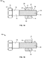
- FIG. 1A shows a 15.875 mm (5/8 inch) fastener 10 having the bolt thread 26 with a bolt pitch of about 2.54 mm (0.100 inch) and the nut thread 30 with a nut pitch of about 2.515 mm (0.099 inch).
- the fastener 10 consists of different fastener sizes having different and corresponding bolt pitches and nut pitches wherein each of the nut pitches has a length that is shorter than a length of the corresponding bolt pitch.
- the initial contact and engagement between the nut thread 30 and the bolt thread 26 is located at the inner most pitch 31 of the nut thread 30, i.e., that closest to the sheet line of the work piece and the second end 19 of the nut 14, and, thus, results in thread engagement at the inner most portion of the nut thread 30 closest to the sheet line.
- the nut thread 30 includes a nut pitch having a length that is longer than a length of the bolt pitch of the bolt thread 26. In another embodiment, the nut thread 30 includes a nut pitch having a length that is longer than a length of a bolt pitch of the bolt thread 26. In another embodiment, FIG. 1B shows a 15.875 mm (5/8 inch) fastener 10 having the bolt thread 26 with a bolt pitch of about 2.54 mm (0.100 inch) and the nut thread 30 with a nut pitch of about 2.515 (0.101 inch).
- the fastener 10 consists of different fastener sizes having different and corresponding bolt pitches and nut pitches wherein each of the nut pitches has a length that is longer than a length of the corresponding bolt pitch.
- the initial contact and engagement between the nut thread 30 and the bolt thread 26 is located at the outer most pitch 33 of the nut thread 30, i.e., that farthest from the sheet line and the second end 19 of the nut 14, and thus results in thread engagement at the outer most portion of the nut thread 30 from the sheet line of the work piece.
- the nut 14 is made from 1045 steel. In another embodiment, the nut 14 is made from 1010 steel. In another embodiment, the nut 14 is made from 1215 steel. In another embodiment, the nut 14 is made from aluminum.
- the fastener 10 is able to achieve lock creation (vibration resistance) at lower clamp loads and at lower torque.
- this mismatch concentrates the initial clamp at one end of the nut thread 30 and incrementally engages more thread length as the clamp increases, as shown in FIGS. 1A and 1B . This incremental engagement allows for lock formation at much lower clamp loads and torques, and thus, a more vibration resistant fastener in an under-tightened scenario.
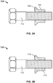
- FIGS. 2A and 2B disclose embodiments of a fastener 110 having a bolt 112 and a nut 114.
- the embodiments of the fastener 110 shown in FIGS. 2A and 2B are constructed and function similar to the respective fasteners 10 shown in FIGS. 1A and 1B , except that the nut 114 includes a flange 115 at one end thereof.
- the flange 115 prevents dilation of the nut 114 as the clamp load increases.
- the nut 114 allows for less raw material usage, resulting in cost savings.
- the flange 115 of the nut 114 shown in FIG. 2A (i.e., with the nut pitch being shorter than the bolt pitch) will prevent dilation thereof.
- the flange 115 of the nut 114 shown in FIG. 2B (i.e., with the nut pitch being longer than the bolt pitch and where initial contact is made on the outermost nut pitch), may not prevent dilation of the nut 114.
- an additional heat treating process on the nut 114 as described below addresses this scenario.
- FIGS. 3A and 3B illustrate embodiments of hardness profiles of the nut 114.
- the hardness profiles present hardness gradations from one end of the nut 114 to the other end of the nut 114.
- the softer end of the gradation will be on the end of the initial pitch contact.
- the hardness of the nut 114 then increases gradually until the other end of the nut 114 is reached.
- the harder end of the nut 114 can then be oriented toward the end that has a tendency to dilate.
- the harder material provides higher hoop strength and therefore will resist dilation.
- the harder material also increases the tensile strength of the fastener 110, and thus, allows for further shortening of the nut 114 in order to further reduce material weight and cost.
- the size of the nut 114 can be reduced by 10% to 20% of a standard nut.
- the hardness of the nut 114 increases from a first end 117 thereof to a second end 119 thereof.
- area A1 has a first hardness in a range of approximately Rc 20 to approximately Rc 60;
- area A2 has a second hardness in a range of approximately Rb 20 to approximately Rc 60; and
- area A3 has a third hardness in a range of approximately Rb 20 to approximately Rb 100.
- the softer end of the gradation will be towards the end of the initial pitch contact, i.e., located proximate to the second end 119 of the nut 114.
- the hardness of the nut 114 increases gradually from the first end 117 thereof to the second end 119 thereof.
- the transition from the first hardness of the area A1 to the second hardness of the area A2 is abrupt.
- the transition from the first hardness of the area A2 to the second hardness of the area A3 is abrupt.
- the transition from the first hardness of the area A1 to the second hardness of the area A2 is abrupt, while the transition from the second hardness of the area A2 to the third hardness of the area A3 is abrupt.
- the term "abrupt" means the transition from one hardness of one area to another hardness of another adjacent area over an area that has a width of less than or equal to three pitch lengths of the nut 114.
- the nut 114 includes only two hardness areas.
- the nut 114 includes four hardness areas.
- the nut 114 includes five hardness areas.
- the nut 114 includes more than five hardness areas.
- the first hardness of the nut 114 increases from the second end 119 to the first end 117 thereof.
- area A1 has a first hardness in a range of approximately Rb 20 to approximately Rb 100;
- area A2 has a second hardness in a range of approximately Rb 20 to approximately Rc 60; and
- area A3 has a third hardness in a range of approximately Rc 20 to approximately Rc 60.
- the softer end of the gradation will be towards the end of the initial pitch contact, i.e., located proximate to the first end 117 of the nut 114.
- the hardness of the nut 114 increases gradually from the second end 119 thereof to the first end 117 thereof.
- the transition from the first hardness of the area A1 to the second hardness of the area A2 is abrupt.
- the transition from the second hardness of the area A2 to the third hardness of the area A3 is abrupt.
- the transition from the first hardness of the area A1 to the second hardness of the area A2 is abrupt, while the transition from the second hardness of the area A2 to the third hardness of the area A3 is abrupt.
- the term "abrupt” means the transition from one hardness of one area to another hardness of another adjacent area over an area that has a width of less than or equal to three pitch lengths of the nut 114.
- the nut 114 includes only two hardness areas.
- the nut 114 includes four hardness areas.
- the nut 114 includes five hardness areas.
- the nut 114 includes more than five hardness areas.
- FIG. 4A , B shows an embodiment of the fastener 110 with the bolt 112 and the nut 114 engaging one another.
- at least one portion of the nut thread 130 of the nut 114 located proximate to the second end 119 thereof is locally softened for locking, while a remaining portion of the nut thread 130 is hardened for resisting dilation and achieving higher tensile.
- the at least one portion of the nut thread 130 includes a length that is approximately equal to at least a portion of a pitch thread length of the nut thread 130.
- the at least one portion of the nut thread 130 includes a length that is approximately equal to one pitch thread length of the nut thread 130. In another embodiment, the at least one portion of the nut thread 130 includes a length that is approximately equal to a plurality of pitch thread lengths of the nut thread 130. In another embodiment, the at least one portion of the nut thread 130 includes a length that is within a range between one pitch thread length of the nut thread 130 and two pitch thread lengths of the nut thread 130. In an embodiment of the present disclosure, the at least one portion of the nut thread 130 is softened. In an embodiment of the present disclosure, the at least one portion of the nut thread 130 is induction annealed. In other embodiments, the at least one portion of the nut thread 130 is locally softened by other means known in the art.
- the nut 114 material is 1045 steel. In another embodiment, the nut 14 is made from 1010 steel. In another embodiment, the nut 14 is made from 1215 steel. In another embodiment, the nut 14 is made from aluminum. In an embodiment of the present disclosure, the nut thread 130 lowers the minimum clamp load in a range of about 20% to 25% of the target clamp. In another embodiment, the nut thread 130 lowers the minimum clamp load about 50% of the target clamp. In an embodiment of the present disclosure, the nut thread 130 has a nut pitch that is shorter than the bolt pitch of the bolt thread 126, therefore allowing the nut thread 130 to embed into the bolt thread 126 before the flanks of the nut thread 130 contact the bolt thread 126.
- the mismatch of the nut pitch of the nut thread 130 and the bolt pitch of the bolt thread 126 allows for a rough field estimation of the clamp being generated by the installation method. This estimation can be made by observing the amount of thread engagement between the nut thread 130 and the bolt thread 126.
- 34.925 mm (1 3/8 inch) nuts 114 were used so the degree of embedment was easier to observe.
- Each of these nuts 114 was installed in a Skidmore Wilhelm test fixture at four clamp loads (27,215 kgf (60,000 Ibf), 36,287 kgf (80,000 Ibf), 45,359 kgf (100,000 Ibf), and 54,431 kgf (120,000 Ibf)). The length of embedment would then be a rough indicator of the clamp achieved, which is helpful in evaluating the quality of the installation without instrumentation.
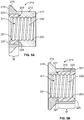
- FIGS. 5A and 5B show other embodiments nuts 214, 314, respectively.
- the embodiments of the nuts 214, 314 shown in FIGS. 5A and 5B are constructed and function similar to the nut 114 shown in FIGS. 2A through 4B , except as otherwise noted.
- the nut 214 includes a nut body 213 having a first end 217 and a second end 219 opposite the first end 217, a flange 215 formed at the second end 219, and an aperture 211 extending from the first end 217 to the second end 219.
- the nut body 213 includes a centrally-located, annular countersunk aperture 221 formed within the second end 219.
- the nut 214 includes an annular insert 223 that is sized and shaped to be inserted into and positioned within the countersunk aperture 221. In an embodiment of the present disclosure, there is an interference fit between the insert 223 and the aperture 221.
- the insert 223 includes a first end 225 and a second end 227 opposite the first end 225 which define a width W of the insert 223. In an embodiment of the present disclosure, when the insert 223 is inserted within the aperture 221 of the nut body 213, the second end 227 of the insert 223 is flush with (or substantially flush with) the second end 219 of the nut body 213.
- the nut 214 (i.e., the nut body 213 and the insert 223) is pre-tapped with an internal nut thread 230 extending from the first end 217 to the second end 219.
- the width W of the insert 223 is so chosen such that the insert 223 extends over a length of or about three nut pitches of the nut thread 230, as shown in FIG. 5A .
- the width W of the insert 223 is so chosen such that the insert 223 extends over a length of less than three nut pitches of the nut thread 230.
- the width W of the insert 223 is so chosen such that the insert 223 extends over a length of more than three nut pitches of the nut thread 230.
- the nut pitch of the nut thread 230 has a length that is shorter than a length of the bolt pitch of a bolt thread.
- the nut body 213 is made from a first material and the insert 223 is made from a second material that is softer than the first material of the nut body 213.
- the first material of the nut body 213 is made of steel and the second material of the insert 223 is made of a softer steel.
- the first material of the nut body 213 is made of steel and the second material of the insert 223 is made of the same steel as the nut body 213 but having a lower hardness.
- the insert 223 is made of aluminum, plastic, brass, or bronze.
- the initial contact and engagement between the nut thread 230 and the bolt thread is located at the inner most pitch 231 of the nut thread 230, i.e., that closest to the sheet line of the work piece and the second end 219 of the nut 214, and, thus, results in thread engagement at the inner most portion of the nut thread 230 closest to the sheet line.
- the nut body 213 is made from a first material and the insert 223 is made from a second material that is harder than the first material of the nut body 213.
- the first material of the nut body 213 is made of steel and the second material of the insert 223 is made of a harder steel.
- the first material of the nut body 213 is made of steel and the second material of the insert 223 is made of the same steel as the nut body 213 but having a higher hardness.
- the initial contact and engagement between the nut thread 230 and the bolt thread is located at the outer most pitch 233 of the nut thread 230, i.e., that farthest from the sheet line and the second end 319 of the nut 314, and thus results in thread engagement at the outer most portion of the nut thread 330 from the sheet line of the work piece.
- the nut 314 includes a nut body 313 having a first end 317 and a second end 319 opposite the first end 317, an aperture 311 extending from the first end 317 to the second end 319, and a flange 315 formed at the second end 319.
- the nut body 313 includes a centrally-located, annular countersunk aperture 321 formed within the first end 317.
- the nut 314 includes an annular insert 323 that is sized and shaped to be inserted into and positioned within the aperture 321. In an embodiment of the present disclosure, there is an interference fit between the insert 323 and the aperture 321.
- the insert 323 includes a first end 325 and a second end 327 opposite the first end 325 which define a width W of the insert 323.
- the first end 325 of the insert 323 is flush with (or substantially flush with) the first end 317 of the nut body 313.
- the nut 314 i.e., the nut body 313 and the insert 323 is pre-tapped with an internal nut thread 330 extending from the first end 317 to the second end 319.
- the width W of the insert 323 is so chosen such that the insert 323 extends over a length of or about five nut pitches of the nut thread 330, as shown in FIG. 5B . In another embodiment, the width W of the insert 323 is so chosen such that the insert 323 extends over a length of less than five nut pitches of the nut thread 330. In another embodiment, the width W of the insert 323 is so chosen such that the insert 323 extends over a length of more than five nut pitches of the nut thread 330.
- the nut pitch of the nut thread 330 has a length that is shorter than a length of the bolt pitch of a bolt thread.
- the nut body 313 is made from a first material and the insert 223 is made from a second material that is harder than the first material of the nut body 313.
- the first material of the nut body 313 is made of steel and the second material of the insert 223 is made of a harder steel.
- the first material of the nut body 313 is made of steel and the second material of the insert 323 is made of the same steel as the nut body 313 but having a higher hardness.
- the initial contact and engagement between the nut thread 330 and the bolt thread is located at the inner most pitch 331 of the nut thread 330, i.e., that closest to the sheet line of the work piece and the second end 319 of the nut 314, and, thus, results in thread engagement at the inner most portion of the nut thread 330 closest to the sheet line.
- the nut body 313 is made from a first material and the insert 323 is made from a second material that is softer than the first material of the nut body 313.
- the first material of the nut body 313 is made of steel and the second material of the insert 323 is made of a softer steel.
- the first material of the nut body 313 is made of steel and the second material of the insert 323 is made of the same steel as the nut body 313 but having a lower hardness.
- the initial contact and engagement between the nut thread 330 and the bolt thread is located at the outer most pitch 333 of the nut thread 330, i.e., that farthest from the sheet line and the second end 319 of the nut 314, and thus results in thread engagement at the outer most portion of the nut thread 330 from the sheet line of the work piece.
Description
- This application relates to and claims the benefit of commonly owned, co-pending
U.S. Provisional Application Serial No. 61/908,922 - The present invention relates to a fastening system and, more particularly, to a vibration-resistant fastening system that includes a nut and a high fatigue strength bolt.
- A free running or prevailing torque nut that forms a vibration proof lock when tightened is desirable. The lock is formed by allowing the bolt thread to embed into the relatively softer nut thread. Reducing material weight and costs of the nut would be desirable.
- The document
EP 0 065 344 A1 relates to a female fastener for assembly with a male fastener having a substantially uniform thread of substantially uniform pitch and including a top flank and a bottom flank intersecting to define a crest, said female fastener having a substantially uniform thread of substantially uniform pitch sized to receive the male thread and having a top flank and a bottom flank with a wedge ramp at the root thereof; said wedge ramp being disposed at an acute angle to the central axis of said female fastener and converging in the direction of the surface of said female fastener adapted to receive clamp loads. The pitch of said female thread is greater than the pitch of the male thread with which it is to be used, the number of said female thread convolutions, the pitch on the male fastener and the axial length of said ramp bearing a relationship to one another whereby said female fastener is placed in axial compression when all of the threads thereof are engaged on said male fastener. -
WO 2007/109751 A2 discloses a fastener that has portions thereof selectively hardened. - The present invention relates to a fastener according to independent claims 1 and 6 whereas further developments of the inventive fastener are provided in the sub-claims, respectively.
- In an embodiment of the present disclosure, a fastener, comprising a bolt including an elongated shank having a first end, a second end opposite the first end, and a threaded portion having an external bolt thread, wherein the bolt thread includes a bolt pitch; and a nut including a first end, a second end opposite the first end of the nut, and an internal nut thread extending between the first and second ends of the nut and adapted to engage threadedly the bolt thread of the bolt, wherein the nut thread includes a nut pitch, wherein the bolt pitch of the bolt thread of the bolt is mismatched with the nut pitch of the nut thread of the nut. In an embodiment of the present disclosure, the nut pitch of the nut thread of the nut is shorter than the bolt pitch of the bolt thread of the bolt. In an embodiment of the present disclosure, when the nut thread of the nut engages the bolt thread of the bolt, an initial contact and engagement between the nut thread and the bolt thread is located at a pitch of the nut pitch that is proximate to the first end of the nut. In an embodiment of the present disclosure, the nut pitch of the nut thread of the nut is longer than the bolt pitch of the bolt thread of the bolt. In an embodiment of the present disclosure, when the nut thread of the nut engages the bolt thread of the bolt, an initial contact and engagement between the nut thread and the bolt thread is located at a pitch of the nut pitch that is proximate to the second end of the nut. In an embodiment of the present disclosure, the nut includes a flange located at the first end thereof.
- In an embodiment of the present disclosure, a bolt including an elongated shank having a first end, a second end opposite the first end, and a threaded portion having an external bolt thread, wherein the bolt thread includes a bolt pitch; and a nut including a nut body having a first end, a second end opposite the first end of the nut body, and a countersunk aperture, an insert positioned within the countersunk aperture, and an internal nut thread extending between the first and second ends of the nut body and adapted to engage threadedly the bolt thread of the bolt, wherein the nut thread includes a nut pitch, wherein the bolt pitch of the bolt thread of the bolt is mismatched with the nut pitch of the nut thread of the nut.
- In an embodiment of the present disclosure, the nut pitch of the nut thread of the nut is shorter than the bolt pitch of the bolt thread of the bolt. In an embodiment of the present disclosure, the countersunk aperture is located at the second end of the nut body. In an embodiment of the present disclosure, the nut body is made from a first material and the insert is made from a second material that is softer than the first material. In an embodiment of the present disclosure, when the nut thread of the nut engages the bolt thread of the bolt, an initial contact and engagement between the nut thread and the bolt thread is located at a pitch of the nut pitch that is proximate to the second end of the nut.
- In an embodiment of the present disclosure, countersunk aperture is located at the first end of the nut body. In an embodiment of the present disclosure, the nut body is made from a first material and the insert is made from a second material that is harder than the first material. In an embodiment of the present disclosure, the nut thread of the nut engages the bolt thread of the bolt, an initial contact and engagement between the nut thread and the bolt thread is located at a pitch of the nut pitch that is proximate to the second end of the nut.
- In an embodiment of the present disclosure, the nut pitch of the nut thread of the nut is longer than the bolt pitch of the bolt thread of the bolt. In an embodiment of the present disclosure, the countersunk aperture is located at the second end of the nut body. In an embodiment of the present disclosure, the nut body is made from a first material and the insert is made from a second material that is harder than the first material. In an embodiment of the present disclosure, the nut thread of the nut engages the bolt thread of the bolt, an initial contact and engagement between the nut thread and the bolt thread is located at a pitch of the nut pitch that is proximate to the first end of the nut.
- In an embodiment of the present disclosure, the countersunk aperture is located at the first end of the nut body. In an embodiment of the present disclosure, the nut body is made from a first material and the insert is made from a second material that is softer than the first material. In an embodiment of the present disclosure, the nut thread of the nut engages the bolt thread of the bolt, an initial contact and engagement between the nut thread and the bolt thread is located at a pitch of the nut pitch that is proximate to the first end of the nut.
- In an embodiment of the present disclosure, a nut, comprising a first end, a second end opposite the first end, an internal nut thread extending from the first end to the second end, and a hardness, wherein the hardness gradationally changes between the first and second ends. In an embodiment of the present disclosure, the nut includes a first hardness area extending between the first end and a first boundary located intermediate the first and second ends, a second hardness area extending from the first boundary to a second boundary located distal from the first boundary and towards the second end, and a third hardness area extending from the first boundary to the second end. In an embodiment of the present disclosure, the hardness within the first hardness area includes a first hardness, the hardness within the second hardness area includes a second hardness, and the hardness within the third hardness area includes a third hardness. In an embodiment of the present disclosure, the first hardness is a range of approximately
Rc 20 to approximately Rc 60, the second hardness is a range of approximatelyRb 20 to approximately Rc 60, and the third hardness is in a range of approximatelyRb 20 to approximately Rb 100. In an embodiment of the present disclosure, the hardness increases gradually from the first end to the second end. In an embodiment of the present disclosure, a transition from the first hardness to the second hardness is abrupt, and wherein a transition from the second hardness to the third hardness is abrupt. - In another embodiment, the first hardness is in a range of approximately
Rb 20 to approximately Rb 100, the second hardness is a range of approximatelyRb 20 to approximately Rc 60, and the third hardness is in a range of approximatelyRc 20 to approximately Rc 60. In an embodiment of the present disclosure, the hardness increases gradually from the second end to the first end. In an embodiment of the present disclosure, a transition from the first hardness to the second hardness is abrupt, and wherein a transition from the second hardness to the third hardness is abrupt. - In an embodiment of the present disclosure, at least one portion of the nut thread located proximate to the second end is locally softened, and a remaining portion of the nut thread is hardened. In an embodiment of the present disclosure, the at least one portion of the nut thread includes a length that is approximately equal to at least a portion of a pitch thread length of the nut thread. In an embodiment of the present disclosure, the at least one portion of the nut thread includes a length that is approximately equal to one pitch thread length of the nut thread. In an embodiment of the present disclosure, the at least one portion of the nut thread includes a length that is approximately equal to a plurality of pitch thread lengths of the nut thread. In an embodiment of the present disclosure, the at least one portion of the nut thread includes a length that is within a range between one pitch thread length of the nut thread and two pitch thread lengths of the nut thread.
- In an embodiment of the present disclosure, the engagement between the nut thread and the bolt thread provides a visual indication of the amount of clamp generated.
- In an embodiment of the present disclosure, a fastener, comprising a bolt including an elongated shank having a first end, a second end opposite the first end, and a threaded portion having a an external bolt thread, wherein the bolt thread includes a bolt pitch; and a nut including a first end, a second end opposite the first end of the nut, a an internal nut thread extending between the first and second ends of the nut and adapted to engage threadedly the bolt thread of the bolt, wherein the nut thread includes a nut pitch, and a hardness that changes gradationally between the first and second ends of the nut, wherein the bolt pitch of the bolt thread of the bolt is mismatched with the nut pitch of the nut thread of the nut.
- In an embodiment of the present disclosure, the nut pitch of the nut thread of the nut is shorter than the bolt pitch of the bolt thread of the bolt. In an embodiment of the present disclosure, when the nut thread of the nut engages the bolt thread of the bolt, an initial contact and engagement between the nut thread and the bolt thread is located at a pitch of the nut pitch that is proximate to the first end of the nut. In an embodiment of the present disclosure, the nut pitch of the nut thread of the nut is longer than the bolt pitch of the bolt thread of the bolt. In an embodiment of the present disclosure, the nut thread of the nut engages the bolt thread of the bolt, an initial contact and engagement between the nut thread and the bolt thread is located at a pitch of the nut pitch that is proximate to the second end of the nut. In an embodiment of the present disclosure, the nut includes a flange located at the first end thereof.
- In an embodiment of the present disclosure, the nut includes a first hardness area extending between the first end and a first boundary located intermediate the first and second ends, a second hardness area extending from the first boundary to a second boundary located distal from the from the first boundary and towards the second end, and a third hardness area extending from the first boundary to the second end. In an embodiment of the present disclosure, the hardness within the first hardness area includes a first hardness, the hardness within the second hardness area includes a second hardness, and the hardness within the third hardness area includes a third hardness. In an embodiment of the present disclosure, the first hardness is a range of approximately
Rc 20 to approximately Rc 60, the second hardness is a range of approximatelyRb 20 to approximately Rc 60, and the third hardness is in a range of approximatelyRb 20 to approximately Rb 100. In an embodiment of the present disclosure, the hardness increases gradually from the first end to the second end. In an embodiment of the present disclosure, a transition from the first hardness to the second hardness is abrupt, and wherein a transition from the second hardness to the third hardness is abrupt. - In another embodiment, the first hardness is in a range of approximately
Rb 20 to approximately Rb 100, the second hardness is a range of approximatelyRb 20 to approximately Rc 60, and the third hardness is in a range of approximatelyRc 20 to approximately Rc 60. In an embodiment of the present disclosure, the hardness increases gradually from the second end to the first end. In an embodiment of the present disclosure, a transition from the first hardness to the second hardness is abrupt, and wherein a transition from the second hardness to the third hardness is abrupt. - In an embodiment of the present disclosure, the nut wherein at least one portion of the nut thread located proximate to the second end is locally softened, and a remaining portion of the nut thread is hardened. In an embodiment of the present disclosure, at least one portion of the nut thread includes a length that is approximately equal to at least a portion of a pitch thread length of the nut thread. In an embodiment of the present disclosure, the at least one portion of the nut thread includes a length that is approximately equal to one pitch thread length of the nut thread. In an embodiment of the present disclosure, the at least one portion of the nut thread includes a length that is approximately equal to a plurality of pitch thread lengths of the nut thread. In an embodiment of the present disclosure, the at least one portion of the nut thread includes a length that is within a range between one pitch thread length of the nut thread and two pitch thread lengths of the nut thread.
-
-
FIGS. 1A and 1B are side elevational views of embodiments of a fastener having a bolt and a nut, with a nut employed by the fastener shown in cross-section; -
FIGS. 2A and 2B are side elevational views of other embodiments of a fastener having a bolt and a nut, with the nut employed by the fastener shown in cross-section; -
FIGS. 3A and 3B are side cross-sectional views of embodiments of a nut employed by the fasteners shown inFIGS. 2A and 2B ; -
FIG. 4A is a side cross-sectional view of an embodiment of a fastener, showing pre-engagement of a nut thread of a nut with a bolt thread of a bolt; -
FIG. 4B is a side cross-sectional view of the fastener shown inFIG. 4A engaging the nut thread of the nut with the bolt thread of the bolt; and -
FIGS. 5A and 5B are cross-sectional views of other embodiments of a nut. - Referring to
FIGS. 1A and 1B , afastener 10 includes abolt 12 and anut 14 that threadedly mates with thebolt 12 for fastening two work pieces, joints, or the like to one another (not shown in the Figures). In an embodiment of the present disclosure, thebolt 12 is a high fatigue strength bolt made from a first material, while thenut 14 is made from a second material that is softer than that the first material of thebolt 12. In another embodiment, thebolt 12 is a screw. In an embodiment of the present disclosure, thefastener 10 has a structure similar to the fasteners disclosed inU.S. Patent No. 8,465,240 to Corbett et al. , entitled "Advanced Nut and Bolt,". - Still referring to
FIGS. 1A and 1B , in an embodiment of the present disclosure, thebolt 12 includes anelongated shank 16 having afirst end 18 and asecond end 20 opposite thefirst end 18, and anenlarged bolt head 22 located at thefirst end 18. In one or more embodiments, thebolt head 22 can consist of any type of bolt head size and shape known in the art (e.g., hex head, carriage bolt head, truss head, fillister head, etc.). In an embodiment of the present disclosure, theshank 16 includes a threadedportion 24 having anexternal bolt thread 26. In an embodiment of the present disclosure, thebolt thread 26 is a helical thread. In one or more embodiments, thebolt thread 26 of thebolt 12 is similar to those of the BOBTAIL® fasteners manufactured by Alcoa Fastening Systems, which is also disclosed in United States Patent No.7,293,339 to Mercer et al. , entitled "Low Swage Load Fastening System and Method,". An embodiment of the present disclosure of the bolt disclosed inU.S. Patent No. 7,293,339 includes a shallow thread and a large root radius (not shown in the present Figures). In another embodiment, a shallow thread, a wide bolt thread groove (relative to a nut thread crest) and a large root radius of thebolt thread 26 create a larger bolt cross-section and reduce stress concentration, thereby giving thebolt 12 improved fatigue and shear strength in the threadedportion 24. In an embodiment of the present disclosure, thebolt head 22 need not be included, and thebolt 12 is an unheaded stud (not shown in the Figures). - In an embodiment of the present disclosure, the
bolt 12 is made from 4140 steel. In another embodiment, thebolt 12 is made from 50B35 steel. In another embodiment, thebolt 12 is made from stainless steel. In another embodiment, thebolt 12 is made from titanium. In another embodiment, thebolt 12 is made from aluminum. - Still referring to
FIGS. 1A and 1B , in an embodiment of the present disclosure, thenut 14 includes anexternal hex 28 for facilitating the rotational tightening and loosening of thenut 14 on and from thebolt 12, respectively. Thenut 14 includes afirst end 17 and asecond end 19 opposite thefirst end 17, and a pre-tapped,internal nut thread 30 extending from thefirst end 17 to thesecond end 19. In an embodiment of the present disclosure, thenut thread 30 is a helical thread. In an embodiment of the present disclosure, thenut thread 30 is adapted to engage threadedly thebolt thread 26 of thebolt 12. In an embodiment of the present disclosure, there exists a thread pitch mismatch between thebolt thread 26 and thenut thread 30. In an embodiment of the present disclosure, thenut thread 30 includes a nut pitch having a length that is shorter than a length of the bolt pitch of thebolt thread 26. In an embodiment of the present disclosure,FIG. 1A shows a 15.875 mm (5/8 inch)fastener 10 having thebolt thread 26 with a bolt pitch of about 2.54 mm (0.100 inch) and thenut thread 30 with a nut pitch of about 2.515 mm (0.099 inch). In other embodiments, thefastener 10 consists of different fastener sizes having different and corresponding bolt pitches and nut pitches wherein each of the nut pitches has a length that is shorter than a length of the corresponding bolt pitch. In an embodiment of the present disclosure, the initial contact and engagement between thenut thread 30 and thebolt thread 26 is located at the innermost pitch 31 of thenut thread 30, i.e., that closest to the sheet line of the work piece and thesecond end 19 of thenut 14, and, thus, results in thread engagement at the inner most portion of thenut thread 30 closest to the sheet line. - In another embodiment, the
nut thread 30 includes a nut pitch having a length that is longer than a length of the bolt pitch of thebolt thread 26. In another embodiment, thenut thread 30 includes a nut pitch having a length that is longer than a length of a bolt pitch of thebolt thread 26. In another embodiment,FIG. 1B shows a 15.875 mm (5/8 inch)fastener 10 having thebolt thread 26 with a bolt pitch of about 2.54 mm (0.100 inch) and thenut thread 30 with a nut pitch of about 2.515 (0.101 inch). In other embodiments, thefastener 10 consists of different fastener sizes having different and corresponding bolt pitches and nut pitches wherein each of the nut pitches has a length that is longer than a length of the corresponding bolt pitch. In an embodiment of the present disclosure, the initial contact and engagement between thenut thread 30 and thebolt thread 26 is located at the outermost pitch 33 of thenut thread 30, i.e., that farthest from the sheet line and thesecond end 19 of thenut 14, and thus results in thread engagement at the outer most portion of thenut thread 30 from the sheet line of the work piece. - In an embodiment of the present disclosure, the
nut 14 is made from 1045 steel. In another embodiment, thenut 14 is made from 1010 steel. In another embodiment, thenut 14 is made from 1215 steel. In another embodiment, thenut 14 is made from aluminum. - In an embodiment of the present disclosure, by implementing a thread pitch mismatch between the
bolt thread 26 and thenut thread 30, thefastener 10 is able to achieve lock creation (vibration resistance) at lower clamp loads and at lower torque. In an embodiment of the present disclosure, this mismatch concentrates the initial clamp at one end of thenut thread 30 and incrementally engages more thread length as the clamp increases, as shown inFIGS. 1A and 1B . This incremental engagement allows for lock formation at much lower clamp loads and torques, and thus, a more vibration resistant fastener in an under-tightened scenario. -
FIGS. 2A and 2B disclose embodiments of afastener 110 having abolt 112 and anut 114. The embodiments of thefastener 110 shown inFIGS. 2A and 2B are constructed and function similar to therespective fasteners 10 shown inFIGS. 1A and 1B , except that thenut 114 includes aflange 115 at one end thereof. In an embodiment of the present disclosure, theflange 115 prevents dilation of thenut 114 as the clamp load increases. In another embodiment, thenut 114 allows for less raw material usage, resulting in cost savings. - In an embodiment of the present disclosure, the
flange 115 of thenut 114 shown inFIG. 2A (i.e., with the nut pitch being shorter than the bolt pitch) will prevent dilation thereof. In another embodiment, theflange 115 of thenut 114 shown inFIG. 2B (i.e., with the nut pitch being longer than the bolt pitch and where initial contact is made on the outermost nut pitch), may not prevent dilation of thenut 114. However, an additional heat treating process on thenut 114 as described below addresses this scenario. -
FIGS. 3A and 3B illustrate embodiments of hardness profiles of thenut 114. In an embodiment of the present disclosure, the hardness profiles present hardness gradations from one end of thenut 114 to the other end of thenut 114. In an embodiment of the present disclosure, the softer end of the gradation will be on the end of the initial pitch contact. In an embodiment of the present disclosure, the hardness of thenut 114 then increases gradually until the other end of thenut 114 is reached. In an embodiment of the present disclosure, the harder end of thenut 114 can then be oriented toward the end that has a tendency to dilate. In an embodiment of the present disclosure, the harder material provides higher hoop strength and therefore will resist dilation. In an embodiment of the present disclosure, the harder material also increases the tensile strength of thefastener 110, and thus, allows for further shortening of thenut 114 in order to further reduce material weight and cost. In an embodiment of the present disclosure, the size of thenut 114 can be reduced by 10% to 20% of a standard nut. - In the embodiment shown in
FIG. 3A , the hardness of thenut 114 increases from afirst end 117 thereof to asecond end 119 thereof. In an embodiment of the present disclosure, area A1 has a first hardness in a range of approximatelyRc 20 to approximately Rc 60; area A2 has a second hardness in a range of approximatelyRb 20 to approximately Rc 60; and area A3 has a third hardness in a range of approximatelyRb 20 to approximately Rb 100. Thus, in an embodiment of the present disclosure, the softer end of the gradation will be towards the end of the initial pitch contact, i.e., located proximate to thesecond end 119 of thenut 114. In an embodiment of the present disclosure, the hardness of thenut 114 increases gradually from thefirst end 117 thereof to thesecond end 119 thereof. In another embodiment, the transition from the first hardness of the area A1 to the second hardness of the area A2 is abrupt. In another embodiment, the transition from the first hardness of the area A2 to the second hardness of the area A3 is abrupt. In another embodiment, the transition from the first hardness of the area A1 to the second hardness of the area A2 is abrupt, while the transition from the second hardness of the area A2 to the third hardness of the area A3 is abrupt. As used herein, the term "abrupt" means the transition from one hardness of one area to another hardness of another adjacent area over an area that has a width of less than or equal to three pitch lengths of thenut 114. In another embodiment, thenut 114 includes only two hardness areas. In another embodiment, thenut 114 includes four hardness areas. In another embodiment, thenut 114 includes five hardness areas. In another embodiment, thenut 114 includes more than five hardness areas. - In the embodiment shown in
FIG. 3B , the first hardness of thenut 114 increases from thesecond end 119 to thefirst end 117 thereof. In an embodiment of the present disclosure, area A1 has a first hardness in a range of approximatelyRb 20 to approximately Rb 100; area A2 has a second hardness in a range of approximatelyRb 20 to approximately Rc 60; and area A3 has a third hardness in a range of approximatelyRc 20 to approximately Rc 60. Thus, in an embodiment of the present disclosure, the softer end of the gradation will be towards the end of the initial pitch contact, i.e., located proximate to thefirst end 117 of thenut 114. In an embodiment of the present disclosure, the hardness of thenut 114 increases gradually from thesecond end 119 thereof to thefirst end 117 thereof. In another embodiment, the transition from the first hardness of the area A1 to the second hardness of the area A2 is abrupt. In another embodiment, the transition from the second hardness of the area A2 to the third hardness of the area A3 is abrupt. In another embodiment, the transition from the first hardness of the area A1 to the second hardness of the area A2 is abrupt, while the transition from the second hardness of the area A2 to the third hardness of the area A3 is abrupt. Once again, as used herein, the term "abrupt" means the transition from one hardness of one area to another hardness of another adjacent area over an area that has a width of less than or equal to three pitch lengths of thenut 114. In another embodiment, thenut 114 includes only two hardness areas. In another embodiment, thenut 114 includes four hardness areas. In another embodiment, thenut 114 includes five hardness areas. In another embodiment, thenut 114 includes more than five hardness areas. -
FIG. 4A , B shows an embodiment of thefastener 110 with thebolt 112 and thenut 114 engaging one another. In an embodiment of the present disclosure, as shown inFIG. 4A , B, at least one portion of thenut thread 130 of thenut 114 located proximate to thesecond end 119 thereof is locally softened for locking, while a remaining portion of thenut thread 130 is hardened for resisting dilation and achieving higher tensile. In an embodiment of the present disclosure, the at least one portion of thenut thread 130 includes a length that is approximately equal to at least a portion of a pitch thread length of thenut thread 130. In another embodiment, the at least one portion of thenut thread 130 includes a length that is approximately equal to one pitch thread length of thenut thread 130. In another embodiment, the at least one portion of thenut thread 130 includes a length that is approximately equal to a plurality of pitch thread lengths of thenut thread 130. In another embodiment, the at least one portion of thenut thread 130 includes a length that is within a range between one pitch thread length of thenut thread 130 and two pitch thread lengths of thenut thread 130. In an embodiment of the present disclosure, the at least one portion of thenut thread 130 is softened. In an embodiment of the present disclosure, the at least one portion of thenut thread 130 is induction annealed. In other embodiments, the at least one portion of thenut thread 130 is locally softened by other means known in the art. - In an embodiment of the present disclosure, the
nut 114 material is 1045 steel. In another embodiment, thenut 14 is made from 1010 steel. In another embodiment, thenut 14 is made from 1215 steel. In another embodiment, thenut 14 is made from aluminum. In an embodiment of the present disclosure, thenut thread 130 lowers the minimum clamp load in a range of about 20% to 25% of the target clamp. In another embodiment, thenut thread 130 lowers the minimum clamp load about 50% of the target clamp. In an embodiment of the present disclosure, thenut thread 130 has a nut pitch that is shorter than the bolt pitch of thebolt thread 126, therefore allowing thenut thread 130 to embed into thebolt thread 126 before the flanks of thenut thread 130 contact thebolt thread 126. - In an embodiment of the present disclosure, the mismatch of the nut pitch of the
nut thread 130 and the bolt pitch of thebolt thread 126 allows for a rough field estimation of the clamp being generated by the installation method. This estimation can be made by observing the amount of thread engagement between thenut thread 130 and thebolt thread 126. As an example, 34.925 mm (1 3/8 inch) nuts 114 were used so the degree of embedment was easier to observe. Each of thesenuts 114 was installed in a Skidmore Wilhelm test fixture at four clamp loads (27,215 kgf (60,000 Ibf), 36,287 kgf (80,000 Ibf), 45,359 kgf (100,000 Ibf), and 54,431 kgf (120,000 Ibf)). The length of embedment would then be a rough indicator of the clamp achieved, which is helpful in evaluating the quality of the installation without instrumentation. -
FIGS. 5A and 5B showother embodiments nuts nuts FIGS. 5A and 5B are constructed and function similar to thenut 114 shown inFIGS. 2A through 4B , except as otherwise noted. Referring toFIG. 5A , in an embodiment of the present disclosure, thenut 214 includes anut body 213 having afirst end 217 and asecond end 219 opposite thefirst end 217, aflange 215 formed at thesecond end 219, and anaperture 211 extending from thefirst end 217 to thesecond end 219. In an embodiment of the present disclosure, thenut body 213 includes a centrally-located, annularcountersunk aperture 221 formed within thesecond end 219. In an embodiment of the present disclosure, thenut 214 includes anannular insert 223 that is sized and shaped to be inserted into and positioned within the countersunkaperture 221. In an embodiment of the present disclosure, there is an interference fit between theinsert 223 and theaperture 221. In an embodiment of the present disclosure, theinsert 223 includes afirst end 225 and asecond end 227 opposite thefirst end 225 which define a width W of theinsert 223. In an embodiment of the present disclosure, when theinsert 223 is inserted within theaperture 221 of thenut body 213, thesecond end 227 of theinsert 223 is flush with (or substantially flush with) thesecond end 219 of thenut body 213. In an embodiment of the present disclosure, the nut 214 (i.e., thenut body 213 and the insert 223) is pre-tapped with aninternal nut thread 230 extending from thefirst end 217 to thesecond end 219. In an embodiment of the present disclosure, the width W of theinsert 223 is so chosen such that theinsert 223 extends over a length of or about three nut pitches of thenut thread 230, as shown inFIG. 5A . In another embodiment, the width W of theinsert 223 is so chosen such that theinsert 223 extends over a length of less than three nut pitches of thenut thread 230. In another embodiment, the width W of theinsert 223 is so chosen such that theinsert 223 extends over a length of more than three nut pitches of thenut thread 230. - Still referring to
FIG. 5A , in an embodiment of the present disclosure, the nut pitch of thenut thread 230 has a length that is shorter than a length of the bolt pitch of a bolt thread. In an embodiment of the present disclosure, thenut body 213 is made from a first material and theinsert 223 is made from a second material that is softer than the first material of thenut body 213. In an embodiment of the present disclosure, the first material of thenut body 213 is made of steel and the second material of theinsert 223 is made of a softer steel. In another embodiment, the first material of thenut body 213 is made of steel and the second material of theinsert 223 is made of the same steel as thenut body 213 but having a lower hardness. In other embodiments, theinsert 223 is made of aluminum, plastic, brass, or bronze. In an embodiment of the present disclosure, the initial contact and engagement between thenut thread 230 and the bolt thread is located at the innermost pitch 231 of thenut thread 230, i.e., that closest to the sheet line of the work piece and thesecond end 219 of thenut 214, and, thus, results in thread engagement at the inner most portion of thenut thread 230 closest to the sheet line. - Still referring to
FIG. 5A , in another embodiment, thenut body 213 is made from a first material and theinsert 223 is made from a second material that is harder than the first material of thenut body 213. In an embodiment of the present disclosure, the first material of thenut body 213 is made of steel and the second material of theinsert 223 is made of a harder steel. In another embodiment, the first material of thenut body 213 is made of steel and the second material of theinsert 223 is made of the same steel as thenut body 213 but having a higher hardness. In an embodiment of the present disclosure, the initial contact and engagement between thenut thread 230 and the bolt thread is located at the outermost pitch 233 of thenut thread 230, i.e., that farthest from the sheet line and thesecond end 319 of thenut 314, and thus results in thread engagement at the outer most portion of thenut thread 330 from the sheet line of the work piece. - Referring to
FIG. 5B , in an embodiment of the present disclosure, thenut 314 includes anut body 313 having afirst end 317 and asecond end 319 opposite thefirst end 317, anaperture 311 extending from thefirst end 317 to thesecond end 319, and aflange 315 formed at thesecond end 319. In an embodiment of the present disclosure, thenut body 313 includes a centrally-located, annularcountersunk aperture 321 formed within thefirst end 317. In an embodiment of the present disclosure, thenut 314 includes anannular insert 323 that is sized and shaped to be inserted into and positioned within theaperture 321. In an embodiment of the present disclosure, there is an interference fit between theinsert 323 and theaperture 321. In an embodiment of the present disclosure, theinsert 323 includes afirst end 325 and asecond end 327 opposite thefirst end 325 which define a width W of theinsert 323. In an embodiment of the present disclosure, when theinsert 323 is inserted within theaperture 321 of thenut body 313, thefirst end 325 of theinsert 323 is flush with (or substantially flush with) thefirst end 317 of thenut body 313. In an embodiment of the present disclosure, the nut 314 (i.e., thenut body 313 and the insert 323) is pre-tapped with aninternal nut thread 330 extending from thefirst end 317 to thesecond end 319. In an embodiment of the present disclosure, the width W of theinsert 323 is so chosen such that theinsert 323 extends over a length of or about five nut pitches of thenut thread 330, as shown inFIG. 5B . In another embodiment, the width W of theinsert 323 is so chosen such that theinsert 323 extends over a length of less than five nut pitches of thenut thread 330. In another embodiment, the width W of theinsert 323 is so chosen such that theinsert 323 extends over a length of more than five nut pitches of thenut thread 330. - Still referring to
FIG. 5B , in an embodiment of the present disclosure, the nut pitch of thenut thread 330 has a length that is shorter than a length of the bolt pitch of a bolt thread. In an embodiment of the present disclosure, thenut body 313 is made from a first material and theinsert 223 is made from a second material that is harder than the first material of thenut body 313. In an embodiment of the present disclosure, the first material of thenut body 313 is made of steel and the second material of theinsert 223 is made of a harder steel. In another embodiment, the first material of thenut body 313 is made of steel and the second material of theinsert 323 is made of the same steel as thenut body 313 but having a higher hardness. In an embodiment of the present disclosure, the initial contact and engagement between thenut thread 330 and the bolt thread is located at the innermost pitch 331 of thenut thread 330, i.e., that closest to the sheet line of the work piece and thesecond end 319 of thenut 314, and, thus, results in thread engagement at the inner most portion of thenut thread 330 closest to the sheet line. - Still referring to
FIG. 5B , in another embodiment, thenut body 313 is made from a first material and theinsert 323 is made from a second material that is softer than the first material of thenut body 313. In an embodiment of the present disclosure, the first material of thenut body 313 is made of steel and the second material of theinsert 323 is made of a softer steel. In another embodiment, the first material of thenut body 313 is made of steel and the second material of theinsert 323 is made of the same steel as thenut body 313 but having a lower hardness. In an embodiment of the present disclosure, the initial contact and engagement between thenut thread 330 and the bolt thread is located at the outermost pitch 333 of thenut thread 330, i.e., that farthest from the sheet line and thesecond end 319 of thenut 314, and thus results in thread engagement at the outer most portion of thenut thread 330 from the sheet line of the work piece. - It will be understood that the embodiments described herein are merely exemplary and that a person skilled in the art may make many variations and modifications that remain within the scope of the invention as defined by the appended claims.
Claims (10)
- A fastener (10), comprising:- a bolt (12) including an elongated shank (16) having a first end (18), a second end (20) opposite the first end (18), and a threaded portion (24) having an external bolt thread (26), wherein the bolt thread (26) includes a bolt pitch; and- a nut (14) including a nut body (213) having a first end (217), a second end (219) opposite the first end (217) of the nut body (213), and an internal nut thread (30) extending between the first and second ends (217, 219) of the nut body (213) and adapted to engage threadedly the bolt thread (26) of the bolt (12), wherein the nut thread (30) includes a nut pitch,wherein the bolt pitch of the bolt thread (26) of the bolt (12) is mismatched with the nut pitch of the nut thread (30) of the nut (14),
characterized in that
the nut (14) further comprises a countersunk aperture (221), and an insert (223) positioned within the countersunk aperture (221). - The fastener (10) of Claim 1,
wherein the nut pitch of the nut thread (30) of the nut (14) is shorter than the bolt pitch of the bolt thread (26) of the bolt (12), wherein the countersunk aperture (221) is preferably located at the second end (219) of the nut body (213), wherein the nut body (213) is preferably made from a first material and the insert (223) is preferably made from a second material that is preferably softer than the first material, wherein when the nut thread (30) of the nut (14) engages the bolt thread (26) of the bolt (12), an initial contact and engagement between the nut thread (30) and the bolt thread (26) is preferably located at a pitch of the nut pitch that is proximate to the second end of the nut (14). - The fastener (10) of Claim 1,
wherein the nut pitch of the nut thread (30) of the nut (14) is shorter than the bolt pitch of the bolt thread (26) of the bolt (12), wherein the countersunk aperture (221) is preferably located at the first end (217) of the nut body (213), wherein the nut body (213) is preferably made from a first material and the insert (223) is preferably made from a second material that is preferably harder than the first material, and wherein when the nut thread (30) of the nut (14) engages the bolt thread (26) of the bolt (12), an initial contact and engagement between the nut thread (30) and the bolt thread (26) is preferably located at a pitch of the nut pitch that is proximate to the second end of the nut (14). - The fastener (10) of Claim 1,
wherein the nut pitch of the nut thread (30) of the nut (14) is longer than the bolt pitch of the bolt thread (26) of the bolt (12), wherein the countersunk aperture (221) is preferably located at the second end (219) of the nut body (213), wherein the nut body (213) is preferably made from a first material and the insert (223) is preferably made from a second material that is preferably harder than the first material, and wherein when the nut thread (30) of the nut (14) engages the bolt thread (26) of the bolt (12), an initial contact and engagement between the nut thread (30) and the bolt thread (26) is preferably located at a pitch of the nut pitch that is proximate to the first end of the nut (14). - The fastener (10) of Claim 1,
wherein the nut pitch of the nut thread (30) of the nut (14) is longer than the bolt pitch of the bolt thread (26) of the bolt (12), wherein the countersunk aperture (221) is preferably located at the first end (217) of the nut body (213), wherein the nut body (213) is preferably made from a first material and the insert (223) is preferably made from a second material that is preferably softer than the first material, and wherein when the nut thread (30) of the nut (14) engages the bolt thread (26) of the bolt (12), an initial contact and engagement between the nut thread (30) and the bolt thread (26) is preferably located at a pitch of the nut pitch that is proximate to the first end of the nut (14). - A fastener (10), comprising:- a bolt (12) including an elongated shank (16) having a first end, a second end opposite the first end, and a threaded portion (24) having an external bolt thread (26), wherein the bolt thread (26) includes a bolt pitch; and- a nut (14) including a first end, a second end opposite the first end of the nut (14), an internal nut thread (30) extending between the first and second ends of the nut (14) and adapted to engage threadedly the bolt thread (26) of the bolt (12), wherein the nut thread (30) includes a nut pitch, and a hardness that changes gradationally between the first and second ends of the nut (14),wherein the bolt pitch of the bolt thread (26) of the bolt (12) is mismatched with the nut pitch of the nut thread (30) of the nut (14), wherein at least one portion of the nut thread (30) located proximate to the second end is locally softened, and a remaining portion of the nut thread (30) is hardened.
- The fastener (10) of Claim 6,
wherein the nut pitch of the nut thread (30) of the nut (14) is shorter than the bolt pitch of the bolt thread (26) of the bolt (12), wherein when the nut thread (30) of the nut (14) engages the bolt thread (26) of the bolt (12), an initial contact and engagement between the nut thread (30) and the bolt thread (26) is preferably located at a pitch of the nut pitch that is proximate to the first end of the nut (14); or
wherein the nut pitch of the nut thread (30) of the nut (14) is longer than the bolt pitch of the bolt thread (26) of the bolt (12), wherein when the nut thread (30) of the nut (14) engages the bolt thread (26) of the bolt (12), an initial contact and engagement between the nut thread (30) and the bolt thread (26) is preferably located at a pitch of the nut pitch that is proximate to the second end of the nut (14). - The fastener (10) of Claim 7,
wherein the nut (14) includes a first hardness area extending between the first end and a first boundary located intermediate the first and second ends, a second hardness area extending from the first boundary to a second boundary located distal from the from the first boundary and towards the second end, and a third hardness area extending from the first boundary to the second end,
wherein the hardness within the first hardness area preferably includes a first hardness, the hardness within the second hardness area preferably includes a second hardness, and the hardness within the third hardness area preferably includes a third hardness. - The fastener (10) of Claim 8,
wherein the first hardness is a range of approximately Rc 20 to approximately Rc 60, the second hardness is a range of approximately Rb 20 to approximately Rc 60, and the third hardness is in a range of approximately Rb 20 to approximately Rb 100, wherein the hardness preferably increases gradually from the first end to the second end, or wherein a transition from the first hardness to the second hardness is preferably abrupt, and wherein a transition from the second hardness to the third hardness is preferably abrupt; or
wherein the first hardness is in a range of approximately Rb 20 to approximately Rb 100, the second hardness is a range of approximately Rb 20 to approximately Rc 60, and the third hardness is in a range of approximately Rc 20 to approximately Rc 60, wherein the hardness preferably increases gradually from the second end to the first end, or wherein a transition from the first hardness to the second hardness is preferably abrupt, and wherein a transition from the second hardness to the third hardness is preferably abrupt. - The fastener (10) of Claim 7 or 8,
wherein the at least one portion of the nut thread (30) includes a length that is approximately equal to at least a portion of a pitch thread length of the nut thread (30); or
wherein the at least one portion of the nut thread (30) includes a length that is approximately equal to one pitch thread length of the nut thread (30); or
wherein the at least one portion of the nut thread (30) includes a length that is approximately equal to a plurality of pitch thread lengths of the nut thread (30); or
wherein the at least one portion of the nut thread (30) includes a length that is within a range between one pitch thread length of the nut thread (30) and two pitch thread lengths of the nut thread (30).
Applications Claiming Priority (2)
| Application Number | Priority Date | Filing Date | Title |
|---|---|---|---|
| US201361908922P | 2013-11-26 | 2013-11-26 | |
| PCT/US2014/067413 WO2015081099A1 (en) | 2013-11-26 | 2014-11-25 | Advanced nut and bolt |
Publications (2)
| Publication Number | Publication Date |
|---|---|
| EP3074647A1 EP3074647A1 (en) | 2016-10-05 |
| EP3074647B1 true EP3074647B1 (en) | 2019-10-09 |
Family
ID=52011342
Family Applications (1)
| Application Number | Title | Priority Date | Filing Date |
|---|---|---|---|
| EP14808802.4A Not-in-force EP3074647B1 (en) | 2013-11-26 | 2014-11-25 | Advanced nut and bolt |
Country Status (5)
| Country | Link |
|---|---|
| US (2) | US20150147134A1 (en) |
| EP (1) | EP3074647B1 (en) |
| CN (2) | CN104728240B (en) |
| ES (1) | ES2765512T3 (en) |
| WO (1) | WO2015081099A1 (en) |
Families Citing this family (9)
| Publication number | Priority date | Publication date | Assignee | Title |
|---|---|---|---|---|
| US10655669B2 (en) | 2013-11-26 | 2020-05-19 | Arconic Inc. | Advanced nut and bolt |
| US20150147134A1 (en) * | 2013-11-26 | 2015-05-28 | Alcoa Inc. | Advanced nut and bolt |
| US9845820B2 (en) * | 2014-08-21 | 2017-12-19 | Inspect 100 Ltd. | Thin walled fastener |
| WO2018119847A1 (en) * | 2016-12-29 | 2018-07-05 | 诠丰精密工具股份有限公司 | Threaded screwing engagement structure |
| DE102017101931B4 (en) * | 2017-02-01 | 2022-05-05 | Kamax Holding Gmbh & Co. Kg | High strength screw with a softened threaded end |
| US20190017532A1 (en) * | 2017-07-13 | 2019-01-17 | Ming Yue | Anti-loosening washer |
| CN108741646A (en) * | 2018-05-09 | 2018-11-06 | 兰州理工大学 | A kind of music stand for music teaching convenient for adjusting |
| CN110374980B (en) * | 2019-07-22 | 2020-04-10 | 温州思林工业设计有限公司 | Quick self-locking nut structure and assembling and using method thereof |
| US20220205471A1 (en) * | 2020-12-29 | 2022-06-30 | Dana Automotive Systems Group, Llc | Locking feature for a fastener |
Family Cites Families (54)
| Publication number | Priority date | Publication date | Assignee | Title |
|---|---|---|---|---|
| US197467A (en) * | 1877-11-27 | Improvement in nut and bolt locks | ||
| US1197467A (en) | 1915-05-04 | 1916-09-05 | John Oliver Evans | Bed-warmer. |
| US1884973A (en) | 1927-11-01 | 1932-10-25 | Dardelet Threadlock Corp | Self-locking coupled screw elements |
| US1697118A (en) | 1927-11-01 | 1929-01-01 | Dardelet Threadlock Corp | Self-locking coupled screw element |
| US1922689A (en) * | 1931-07-11 | 1933-08-15 | Hans G H Linnenbruegge | Method of forming screw-threaded members |
| US1953095A (en) | 1931-07-18 | 1934-04-03 | Timken Roller Bearing Co | Detachable bit |
| BE445526A (en) * | 1939-08-02 | |||
| GB567862A (en) * | 1943-08-31 | 1945-03-06 | Frank Birchall | Improvements in and relating to self-locking nuts |
| US2389377A (en) * | 1944-05-19 | 1945-11-20 | Richard C Manning | Lock nut |
| US2429103A (en) * | 1944-07-05 | 1947-10-14 | Mitchell Robert | Threaded fastener |
| US2467483A (en) | 1946-12-09 | 1949-04-19 | Hutchings Herschel | Agricultural tractor |
| US2564029A (en) | 1947-04-11 | 1951-08-14 | Peterson Dana | Nut and bolt construction |
| US2615119A (en) * | 1947-08-21 | 1952-10-21 | Caterpillar Tractor Co | Steel nut and method of making |
| US2684606A (en) | 1952-03-17 | 1954-07-27 | Eugene A Lafreniere | Combination self-threading easy out and lock nut |
| DE1073244B (en) | 1955-12-27 | 1960-01-14 | Heli-Coil Corporation Danbury, Conn (V St A) | Screw connection with a nut body made of relatively white building material |
| BE571794A (en) | 1958-01-07 | |||
| US3258284A (en) | 1963-12-30 | 1966-06-28 | Phipps Orville | Drill bit and rod coupling |
| US3394626A (en) | 1967-03-17 | 1968-07-30 | Harold L. Oliver | Machine screw threads |
| US4019550A (en) * | 1975-06-09 | 1977-04-26 | Abbott Screw & Mfg. Co. | Sealing nut with nylon insert |
| US4171012A (en) | 1975-11-25 | 1979-10-16 | Holmes Horace D | Locking thread construction |
| DE2742098C2 (en) | 1977-09-19 | 1983-01-13 | Rosenthal Technik Ag, 8672 Selb | Endoprosthesis with a metal-ceramic connection |
| US4594039A (en) * | 1981-05-11 | 1986-06-10 | Microdot Inc. | Fastener |
| NO159616C (en) | 1985-06-19 | 1989-01-18 | Harald Kolvereid | L SMUTTER. |
| DE3601389A1 (en) * | 1986-01-18 | 1987-07-23 | Kellermann Fa Rudolf | CONNECTING ELEMENT TYPE OF A SCREW / NUT CONNECTION |
| US4846614A (en) | 1986-12-08 | 1989-07-11 | Rolf Steinbock | Differential thread for transfer of screw thread forces |
| JPH0429607A (en) | 1990-05-23 | 1992-01-31 | Nippon Steel Corp | High-tension bolt excellent in delay breakage resistance characteristic |
| US5139380A (en) * | 1990-11-28 | 1992-08-18 | Pac Fasteners | Scalloped nut and method of construction |
| US5413445A (en) | 1991-11-22 | 1995-05-09 | Aceros Cartellone, S.A. | End link and swivel assemblies for chaincables |
| DE9219017U1 (en) | 1992-03-05 | 1997-01-16 | Schuermann & Hilleke Gmbh | Bolt with self-locking thread and tool for producing such a bolt |
| US5454675A (en) * | 1994-04-26 | 1995-10-03 | Abbott-Interfast Corporation | Sealing nut and method of making same |
| JP3816130B2 (en) | 1994-10-03 | 2006-08-30 | ハック インターナショナル,インコーポレイテッド | High-strength torque type blind bolt with anti-rotation device |
| US5738472A (en) | 1995-10-18 | 1998-04-14 | Honeybee Robotics Inc. | Modified locking thread form for fastener |
| US5779413A (en) * | 1996-02-23 | 1998-07-14 | Fairchild Holding Corp. | Fastener system having improved locking element |
| US5908276A (en) | 1997-01-29 | 1999-06-01 | Lok-Mor, Inc. | Annular engagement lock nut |
| US5865581A (en) | 1997-04-16 | 1999-02-02 | Huck International, Inc. | Free running prevailing torque nut |
| JPH11315820A (en) | 1998-05-07 | 1999-11-16 | Hideo Moroi | Locknut |
| US6749386B2 (en) | 2001-08-20 | 2004-06-15 | Maclean-Fogg Company | Locking fastener assembly |
| GB2383106B (en) | 2001-12-14 | 2004-09-15 | Textron Fastening Syst Ltd | Method of fastening |
| JP2003183735A (en) | 2001-12-18 | 2003-07-03 | Nsk Ltd | Method and apparatus for heat-treating ball screw |
| US20050111934A1 (en) | 2003-11-14 | 2005-05-26 | Ladouceur Harold A. | Self-riveting male fastener and panel assembly |
| EP1590515B1 (en) | 2003-01-29 | 2013-04-10 | Grant Prideco, Inc | Fast make-up fatigue resistant rotary shouldered connection |
| CN100523526C (en) | 2003-02-20 | 2009-08-05 | 康蒂扣件股份公司 | Tapping screw for low ductility material |
| RU2249628C1 (en) | 2003-12-26 | 2005-04-10 | Общество с ограниченной ответственностью "Интелмет НТ" | Round-profiled rolled iron from low-carbon steel for cold die forging of high-strength especially high-profiled fastening members |
| RU2249629C1 (en) | 2003-12-26 | 2005-04-10 | Общество с ограниченной ответственностью "Интелмет НТ" | Round-profiled rolled iron from medium-carbon high-plasticity steel for cold die forging of high-strength especially high-profiled fastening members |
| DE102004021484B4 (en) | 2004-04-30 | 2018-11-29 | Böllhoff Verbindungstechnik GmbH | Method for producing a connection arrangement |
| WO2006100766A1 (en) * | 2005-03-23 | 2006-09-28 | Saga University | Screw |
| US7293339B2 (en) | 2005-06-29 | 2007-11-13 | Huck International, Inc. | Low swage load fastening system and method |
| US7717659B2 (en) | 2005-08-15 | 2010-05-18 | Acumet Intellectual Properties, Llc | Zero-clearance bolted joint |
| US7740436B2 (en) * | 2006-03-22 | 2010-06-22 | R B & W Manufacturing Llc | Clinch nut |
| JP5143407B2 (en) | 2006-12-06 | 2013-02-13 | 株式会社森創 | Game machine board case |
| US20080145185A1 (en) | 2006-12-13 | 2008-06-19 | Alcoa Global Fasteners | Two piece, free running, prevailing torque nut |
| US7802953B2 (en) * | 2007-03-16 | 2010-09-28 | Robert Stephen | Inset panel fastener |
| WO2010080666A1 (en) | 2009-01-06 | 2010-07-15 | Alcoa Inc. | Advanced nut and bolt |
| US20150147134A1 (en) * | 2013-11-26 | 2015-05-28 | Alcoa Inc. | Advanced nut and bolt |
-
2014
- 2014-11-25 US US14/553,476 patent/US20150147134A1/en not_active Abandoned
- 2014-11-25 ES ES14808802T patent/ES2765512T3/en active Active
- 2014-11-25 EP EP14808802.4A patent/EP3074647B1/en not_active Not-in-force
- 2014-11-25 WO PCT/US2014/067413 patent/WO2015081099A1/en active Application Filing
- 2014-11-26 CN CN201410697074.5A patent/CN104728240B/en not_active Expired - Fee Related
- 2014-11-26 CN CN201420731561.4U patent/CN204371870U/en not_active Withdrawn - After Issue
-
2019
- 2019-05-09 US US16/407,439 patent/US11519452B2/en active Active
Non-Patent Citations (1)
| Title |
|---|
| None * |
Also Published As
| Publication number | Publication date |
|---|---|
| US11519452B2 (en) | 2022-12-06 |
| US20190264728A1 (en) | 2019-08-29 |
| WO2015081099A1 (en) | 2015-06-04 |
| CN104728240A (en) | 2015-06-24 |
| CN204371870U (en) | 2015-06-03 |
| EP3074647A1 (en) | 2016-10-05 |
| CN104728240B (en) | 2018-10-30 |
| US20150147134A1 (en) | 2015-05-28 |
| ES2765512T3 (en) | 2020-06-09 |
Similar Documents
| Publication | Publication Date | Title |
|---|---|---|
| EP3074647B1 (en) | Advanced nut and bolt | |
| US10724566B2 (en) | Threaded fastener | |
| EP2238361B1 (en) | Advanced nut and bolt | |
| EP2069647B1 (en) | Load indicating fastener and method of manufacture | |
| EP2092203B1 (en) | Blind stud insert | |
| US10641307B2 (en) | Radiused lead-in for interference fit fasteners | |
| US20210364029A1 (en) | Threaded fastener having a thread crest greater than its thread root and v angles on the crest and root | |
| US10655669B2 (en) | Advanced nut and bolt | |
| US4806054A (en) | Male threaded fastener capable of use with a swaged collar | |
| CN209800516U (en) | Accurate moment control type locknut | |
| JP2007321858A (en) | Screw fastening structure and screw component | |
| US20050191150A1 (en) | Fixing device and method for fixing to a substrate | |
| EP3988804A1 (en) | Screw | |
| US20070237604A1 (en) | Low tolerance threaded fastener | |
| KR20180030837A (en) | Bolt with loosening restriction |
Legal Events
| Date | Code | Title | Description |
|---|---|---|---|
| PUAI | Public reference made under article 153(3) epc to a published international application that has entered the european phase |
Free format text: ORIGINAL CODE: 0009012 |
|
| 17P | Request for examination filed |
Effective date: 20160510 |
|
| AK | Designated contracting states |
Kind code of ref document: A1 Designated state(s): AL AT BE BG CH CY CZ DE DK EE ES FI FR GB GR HR HU IE IS IT LI LT LU LV MC MK MT NL NO PL PT RO RS SE SI SK SM TR |
|
| AX | Request for extension of the european patent |
Extension state: BA ME |
|
| DAX | Request for extension of the european patent (deleted) | ||
| RAP1 | Party data changed (applicant data changed or rights of an application transferred) |
Owner name: ARCONIC INC. |
|
| STAA | Information on the status of an ep patent application or granted ep patent |
Free format text: STATUS: EXAMINATION IS IN PROGRESS |
|
| 17Q | First examination report despatched |
Effective date: 20181022 |
|
| GRAP | Despatch of communication of intention to grant a patent |
Free format text: ORIGINAL CODE: EPIDOSNIGR1 |
|
| STAA | Information on the status of an ep patent application or granted ep patent |
Free format text: STATUS: GRANT OF PATENT IS INTENDED |
|
| INTG | Intention to grant announced |
Effective date: 20190603 |
|
| GRAS | Grant fee paid |
Free format text: ORIGINAL CODE: EPIDOSNIGR3 |
|
| GRAA | (expected) grant |
Free format text: ORIGINAL CODE: 0009210 |
|
| STAA | Information on the status of an ep patent application or granted ep patent |
Free format text: STATUS: THE PATENT HAS BEEN GRANTED |
|
| AK | Designated contracting states |
Kind code of ref document: B1 Designated state(s): AL AT BE BG CH CY CZ DE DK EE ES FI FR GB GR HR HU IE IS IT LI LT LU LV MC MK MT NL NO PL PT RO RS SE SI SK SM TR |
|
| REG | Reference to a national code |
Ref country code: GB Ref legal event code: FG4D |
|
| REG | Reference to a national code |
Ref country code: CH Ref legal event code: EP |
|
| REG | Reference to a national code |
Ref country code: IE Ref legal event code: FG4D |
|
| REG | Reference to a national code |
Ref country code: DE Ref legal event code: R096 Ref document number: 602014054986 Country of ref document: DE |
|
| REG | Reference to a national code |
Ref country code: AT Ref legal event code: REF Ref document number: 1189168 Country of ref document: AT Kind code of ref document: T Effective date: 20191115 |
|
| PGFP | Annual fee paid to national office [announced via postgrant information from national office to epo] |
Ref country code: DE Payment date: 20191119 Year of fee payment: 6 |
|
| REG | Reference to a national code |
Ref country code: SE Ref legal event code: TRGR |
|
| REG | Reference to a national code |
Ref country code: NL Ref legal event code: MP Effective date: 20191009 |
|
| REG | Reference to a national code |
Ref country code: LT Ref legal event code: MG4D |
|
| PGFP | Annual fee paid to national office [announced via postgrant information from national office to epo] |
Ref country code: ES Payment date: 20191202 Year of fee payment: 6 Ref country code: FR Payment date: 20191120 Year of fee payment: 6 Ref country code: IT Payment date: 20191031 Year of fee payment: 6 |
|
| REG | Reference to a national code |
Ref country code: AT Ref legal event code: MK05 Ref document number: 1189168 Country of ref document: AT Kind code of ref document: T Effective date: 20191009 |
|
| PG25 | Lapsed in a contracting state [announced via postgrant information from national office to epo] |
Ref country code: GR Free format text: LAPSE BECAUSE OF FAILURE TO SUBMIT A TRANSLATION OF THE DESCRIPTION OR TO PAY THE FEE WITHIN THE PRESCRIBED TIME-LIMIT Effective date: 20200110 Ref country code: PT Free format text: LAPSE BECAUSE OF FAILURE TO SUBMIT A TRANSLATION OF THE DESCRIPTION OR TO PAY THE FEE WITHIN THE PRESCRIBED TIME-LIMIT Effective date: 20200210 Ref country code: AT Free format text: LAPSE BECAUSE OF FAILURE TO SUBMIT A TRANSLATION OF THE DESCRIPTION OR TO PAY THE FEE WITHIN THE PRESCRIBED TIME-LIMIT Effective date: 20191009 Ref country code: PL Free format text: LAPSE BECAUSE OF FAILURE TO SUBMIT A TRANSLATION OF THE DESCRIPTION OR TO PAY THE FEE WITHIN THE PRESCRIBED TIME-LIMIT Effective date: 20191009 Ref country code: NL Free format text: LAPSE BECAUSE OF FAILURE TO SUBMIT A TRANSLATION OF THE DESCRIPTION OR TO PAY THE FEE WITHIN THE PRESCRIBED TIME-LIMIT Effective date: 20191009 Ref country code: LT Free format text: LAPSE BECAUSE OF FAILURE TO SUBMIT A TRANSLATION OF THE DESCRIPTION OR TO PAY THE FEE WITHIN THE PRESCRIBED TIME-LIMIT Effective date: 20191009 Ref country code: BG Free format text: LAPSE BECAUSE OF FAILURE TO SUBMIT A TRANSLATION OF THE DESCRIPTION OR TO PAY THE FEE WITHIN THE PRESCRIBED TIME-LIMIT Effective date: 20200109 Ref country code: FI Free format text: LAPSE BECAUSE OF FAILURE TO SUBMIT A TRANSLATION OF THE DESCRIPTION OR TO PAY THE FEE WITHIN THE PRESCRIBED TIME-LIMIT Effective date: 20191009 Ref country code: LV Free format text: LAPSE BECAUSE OF FAILURE TO SUBMIT A TRANSLATION OF THE DESCRIPTION OR TO PAY THE FEE WITHIN THE PRESCRIBED TIME-LIMIT Effective date: 20191009 Ref country code: NO Free format text: LAPSE BECAUSE OF FAILURE TO SUBMIT A TRANSLATION OF THE DESCRIPTION OR TO PAY THE FEE WITHIN THE PRESCRIBED TIME-LIMIT Effective date: 20200109 |
|
| PGFP | Annual fee paid to national office [announced via postgrant information from national office to epo] |
Ref country code: GB Payment date: 20191122 Year of fee payment: 6 |
|
| PG25 | Lapsed in a contracting state [announced via postgrant information from national office to epo] |
Ref country code: RS Free format text: LAPSE BECAUSE OF FAILURE TO SUBMIT A TRANSLATION OF THE DESCRIPTION OR TO PAY THE FEE WITHIN THE PRESCRIBED TIME-LIMIT Effective date: 20191009 Ref country code: HR Free format text: LAPSE BECAUSE OF FAILURE TO SUBMIT A TRANSLATION OF THE DESCRIPTION OR TO PAY THE FEE WITHIN THE PRESCRIBED TIME-LIMIT Effective date: 20191009 Ref country code: IS Free format text: LAPSE BECAUSE OF FAILURE TO SUBMIT A TRANSLATION OF THE DESCRIPTION OR TO PAY THE FEE WITHIN THE PRESCRIBED TIME-LIMIT Effective date: 20200224 |
|
| REG | Reference to a national code |
Ref country code: DE Ref legal event code: R082 Ref document number: 602014054986 Country of ref document: DE Representative=s name: MEISSNER BOLTE PATENTANWAELTE RECHTSANWAELTE P, DE Ref country code: DE Ref legal event code: R081 Ref document number: 602014054986 Country of ref document: DE Owner name: HOWMET AEROSPACE INC. (GESELLSCHAFT NACH DEN G, US Free format text: FORMER OWNER: ARCONIC INC., PITTSBURGH, PA., US |
|
| REG | Reference to a national code |
Ref country code: ES Ref legal event code: FG2A Ref document number: 2765512 Country of ref document: ES Kind code of ref document: T3 Effective date: 20200609 |
|
| PG25 | Lapsed in a contracting state [announced via postgrant information from national office to epo] |
Ref country code: AL Free format text: LAPSE BECAUSE OF FAILURE TO SUBMIT A TRANSLATION OF THE DESCRIPTION OR TO PAY THE FEE WITHIN THE PRESCRIBED TIME-LIMIT Effective date: 20191009 |
|
| REG | Reference to a national code |
Ref country code: CH Ref legal event code: PL |
|
| REG | Reference to a national code |
Ref country code: DE Ref legal event code: R097 Ref document number: 602014054986 Country of ref document: DE |
|
| PG2D | Information on lapse in contracting state deleted |
Ref country code: IS |
|
| PG25 | Lapsed in a contracting state [announced via postgrant information from national office to epo] |
Ref country code: EE Free format text: LAPSE BECAUSE OF FAILURE TO SUBMIT A TRANSLATION OF THE DESCRIPTION OR TO PAY THE FEE WITHIN THE PRESCRIBED TIME-LIMIT Effective date: 20191009 Ref country code: MC Free format text: LAPSE BECAUSE OF FAILURE TO SUBMIT A TRANSLATION OF THE DESCRIPTION OR TO PAY THE FEE WITHIN THE PRESCRIBED TIME-LIMIT Effective date: 20191009 Ref country code: LU Free format text: LAPSE BECAUSE OF NON-PAYMENT OF DUE FEES Effective date: 20191125 Ref country code: RO Free format text: LAPSE BECAUSE OF FAILURE TO SUBMIT A TRANSLATION OF THE DESCRIPTION OR TO PAY THE FEE WITHIN THE PRESCRIBED TIME-LIMIT Effective date: 20191009 Ref country code: CZ Free format text: LAPSE BECAUSE OF FAILURE TO SUBMIT A TRANSLATION OF THE DESCRIPTION OR TO PAY THE FEE WITHIN THE PRESCRIBED TIME-LIMIT Effective date: 20191009 Ref country code: LI Free format text: LAPSE BECAUSE OF NON-PAYMENT OF DUE FEES Effective date: 20191130 Ref country code: DK Free format text: LAPSE BECAUSE OF FAILURE TO SUBMIT A TRANSLATION OF THE DESCRIPTION OR TO PAY THE FEE WITHIN THE PRESCRIBED TIME-LIMIT Effective date: 20191009 Ref country code: CH Free format text: LAPSE BECAUSE OF NON-PAYMENT OF DUE FEES Effective date: 20191130 Ref country code: IS Free format text: LAPSE BECAUSE OF FAILURE TO SUBMIT A TRANSLATION OF THE DESCRIPTION OR TO PAY THE FEE WITHIN THE PRESCRIBED TIME-LIMIT Effective date: 20200209 |
|
| PLBE | No opposition filed within time limit |
Free format text: ORIGINAL CODE: 0009261 |
|
| STAA | Information on the status of an ep patent application or granted ep patent |
Free format text: STATUS: NO OPPOSITION FILED WITHIN TIME LIMIT |
|
| REG | Reference to a national code |
Ref country code: BE Ref legal event code: MM Effective date: 20191130 |
|
| PG25 | Lapsed in a contracting state [announced via postgrant information from national office to epo] |
Ref country code: SK Free format text: LAPSE BECAUSE OF FAILURE TO SUBMIT A TRANSLATION OF THE DESCRIPTION OR TO PAY THE FEE WITHIN THE PRESCRIBED TIME-LIMIT Effective date: 20191009 Ref country code: SM Free format text: LAPSE BECAUSE OF FAILURE TO SUBMIT A TRANSLATION OF THE DESCRIPTION OR TO PAY THE FEE WITHIN THE PRESCRIBED TIME-LIMIT Effective date: 20191009 |
|
| PGFP | Annual fee paid to national office [announced via postgrant information from national office to epo] |
Ref country code: SE Payment date: 20191025 Year of fee payment: 6 |
|
| 26N | No opposition filed |
Effective date: 20200710 |
|
| PG25 | Lapsed in a contracting state [announced via postgrant information from national office to epo] |
Ref country code: IE Free format text: LAPSE BECAUSE OF NON-PAYMENT OF DUE FEES Effective date: 20191125 |
|
| PG25 | Lapsed in a contracting state [announced via postgrant information from national office to epo] |
Ref country code: SI Free format text: LAPSE BECAUSE OF FAILURE TO SUBMIT A TRANSLATION OF THE DESCRIPTION OR TO PAY THE FEE WITHIN THE PRESCRIBED TIME-LIMIT Effective date: 20191009 Ref country code: BE Free format text: LAPSE BECAUSE OF NON-PAYMENT OF DUE FEES Effective date: 20191130 |
|
| PG25 | Lapsed in a contracting state [announced via postgrant information from national office to epo] |
Ref country code: CY Free format text: LAPSE BECAUSE OF FAILURE TO SUBMIT A TRANSLATION OF THE DESCRIPTION OR TO PAY THE FEE WITHIN THE PRESCRIBED TIME-LIMIT Effective date: 20191009 |
|
| REG | Reference to a national code |
Ref country code: DE Ref legal event code: R119 Ref document number: 602014054986 Country of ref document: DE |
|
| REG | Reference to a national code |
Ref country code: SE Ref legal event code: EUG |
|
| GBPC | Gb: european patent ceased through non-payment of renewal fee |
Effective date: 20201125 |
|
| PG25 | Lapsed in a contracting state [announced via postgrant information from national office to epo] |
Ref country code: HU Free format text: LAPSE BECAUSE OF FAILURE TO SUBMIT A TRANSLATION OF THE DESCRIPTION OR TO PAY THE FEE WITHIN THE PRESCRIBED TIME-LIMIT; INVALID AB INITIO Effective date: 20141125 Ref country code: MT Free format text: LAPSE BECAUSE OF FAILURE TO SUBMIT A TRANSLATION OF THE DESCRIPTION OR TO PAY THE FEE WITHIN THE PRESCRIBED TIME-LIMIT Effective date: 20191009 |
|
| PG25 | Lapsed in a contracting state [announced via postgrant information from national office to epo] |
Ref country code: SE Free format text: LAPSE BECAUSE OF NON-PAYMENT OF DUE FEES Effective date: 20201126 |
|
| PG25 | Lapsed in a contracting state [announced via postgrant information from national office to epo] |
Ref country code: FR Free format text: LAPSE BECAUSE OF NON-PAYMENT OF DUE FEES Effective date: 20201130 Ref country code: IT Free format text: LAPSE BECAUSE OF NON-PAYMENT OF DUE FEES Effective date: 20201125 |
|
| PG25 | Lapsed in a contracting state [announced via postgrant information from national office to epo] |
Ref country code: GB Free format text: LAPSE BECAUSE OF NON-PAYMENT OF DUE FEES Effective date: 20201125 Ref country code: DE Free format text: LAPSE BECAUSE OF NON-PAYMENT OF DUE FEES Effective date: 20210601 |
|
| REG | Reference to a national code |
Ref country code: ES Ref legal event code: FD2A Effective date: 20220203 |
|
| PG25 | Lapsed in a contracting state [announced via postgrant information from national office to epo] |
Ref country code: ES Free format text: LAPSE BECAUSE OF NON-PAYMENT OF DUE FEES Effective date: 20201126 |
|
| PG25 | Lapsed in a contracting state [announced via postgrant information from national office to epo] |
Ref country code: TR Free format text: LAPSE BECAUSE OF NON-PAYMENT OF DUE FEES Effective date: 20201125 Ref country code: MK Free format text: LAPSE BECAUSE OF FAILURE TO SUBMIT A TRANSLATION OF THE DESCRIPTION OR TO PAY THE FEE WITHIN THE PRESCRIBED TIME-LIMIT Effective date: 20191009 |