JP7598103B2 - Vehicle drive device - Google Patents
Vehicle drive device Download PDFInfo
- Publication number
- JP7598103B2 JP7598103B2 JP2023532013A JP2023532013A JP7598103B2 JP 7598103 B2 JP7598103 B2 JP 7598103B2 JP 2023532013 A JP2023532013 A JP 2023532013A JP 2023532013 A JP2023532013 A JP 2023532013A JP 7598103 B2 JP7598103 B2 JP 7598103B2
- Authority
- JP
- Japan
- Prior art keywords
- electric machine
- rotating electric
- pair
- axis
- output members
- Prior art date
- Legal status (The legal status is an assumption and is not a legal conclusion. Google has not performed a legal analysis and makes no representation as to the accuracy of the status listed.)
- Active
Links
Images


Classifications
-
- B—PERFORMING OPERATIONS; TRANSPORTING
- B60—VEHICLES IN GENERAL
- B60L—PROPULSION OF ELECTRICALLY-PROPELLED VEHICLES; SUPPLYING ELECTRIC POWER FOR AUXILIARY EQUIPMENT OF ELECTRICALLY-PROPELLED VEHICLES; ELECTRODYNAMIC BRAKE SYSTEMS FOR VEHICLES IN GENERAL; MAGNETIC SUSPENSION OR LEVITATION FOR VEHICLES; MONITORING OPERATING VARIABLES OF ELECTRICALLY-PROPELLED VEHICLES; ELECTRIC SAFETY DEVICES FOR ELECTRICALLY-PROPELLED VEHICLES
- B60L15/00—Methods, circuits, or devices for controlling the traction-motor speed of electrically-propelled vehicles
- B60L15/007—Physical arrangements or structures of drive train converters specially adapted for the propulsion motors of electric vehicles
-
- F—MECHANICAL ENGINEERING; LIGHTING; HEATING; WEAPONS; BLASTING
- F16—ENGINEERING ELEMENTS AND UNITS; GENERAL MEASURES FOR PRODUCING AND MAINTAINING EFFECTIVE FUNCTIONING OF MACHINES OR INSTALLATIONS; THERMAL INSULATION IN GENERAL
- F16H—GEARING
- F16H57/00—General details of gearing
- F16H57/02—Gearboxes; Mounting gearing therein
- F16H57/027—Gearboxes; Mounting gearing therein characterised by means for venting gearboxes, e.g. air breathers
-
- F—MECHANICAL ENGINEERING; LIGHTING; HEATING; WEAPONS; BLASTING
- F16—ENGINEERING ELEMENTS AND UNITS; GENERAL MEASURES FOR PRODUCING AND MAINTAINING EFFECTIVE FUNCTIONING OF MACHINES OR INSTALLATIONS; THERMAL INSULATION IN GENERAL
- F16H—GEARING
- F16H57/00—General details of gearing
- F16H57/02—Gearboxes; Mounting gearing therein
- F16H57/037—Gearboxes for accommodating differential gearings
-
- F—MECHANICAL ENGINEERING; LIGHTING; HEATING; WEAPONS; BLASTING
- F16—ENGINEERING ELEMENTS AND UNITS; GENERAL MEASURES FOR PRODUCING AND MAINTAINING EFFECTIVE FUNCTIONING OF MACHINES OR INSTALLATIONS; THERMAL INSULATION IN GENERAL
- F16H—GEARING
- F16H57/00—General details of gearing
- F16H57/04—Features relating to lubrication or cooling or heating
- F16H57/0402—Cleaning of lubricants, e.g. filters or magnets
- F16H57/0404—Lubricant filters
-
- F—MECHANICAL ENGINEERING; LIGHTING; HEATING; WEAPONS; BLASTING
- F16—ENGINEERING ELEMENTS AND UNITS; GENERAL MEASURES FOR PRODUCING AND MAINTAINING EFFECTIVE FUNCTIONING OF MACHINES OR INSTALLATIONS; THERMAL INSULATION IN GENERAL
- F16H—GEARING
- F16H57/00—General details of gearing
- F16H57/04—Features relating to lubrication or cooling or heating
- F16H57/0412—Cooling or heating; Control of temperature
- F16H57/0415—Air cooling or ventilation; Heat exchangers; Thermal insulations
- F16H57/0417—Heat exchangers adapted or integrated in the gearing
-
- F—MECHANICAL ENGINEERING; LIGHTING; HEATING; WEAPONS; BLASTING
- F16—ENGINEERING ELEMENTS AND UNITS; GENERAL MEASURES FOR PRODUCING AND MAINTAINING EFFECTIVE FUNCTIONING OF MACHINES OR INSTALLATIONS; THERMAL INSULATION IN GENERAL
- F16H—GEARING
- F16H57/00—General details of gearing
- F16H57/04—Features relating to lubrication or cooling or heating
- F16H57/0434—Features relating to lubrication or cooling or heating relating to lubrication supply, e.g. pumps; Pressure control
- F16H57/0436—Pumps
-
- F—MECHANICAL ENGINEERING; LIGHTING; HEATING; WEAPONS; BLASTING
- F16—ENGINEERING ELEMENTS AND UNITS; GENERAL MEASURES FOR PRODUCING AND MAINTAINING EFFECTIVE FUNCTIONING OF MACHINES OR INSTALLATIONS; THERMAL INSULATION IN GENERAL
- F16H—GEARING
- F16H57/00—General details of gearing
- F16H57/04—Features relating to lubrication or cooling or heating
- F16H57/0434—Features relating to lubrication or cooling or heating relating to lubrication supply, e.g. pumps; Pressure control
- F16H57/0441—Arrangements of pumps
-
- F—MECHANICAL ENGINEERING; LIGHTING; HEATING; WEAPONS; BLASTING
- F16—ENGINEERING ELEMENTS AND UNITS; GENERAL MEASURES FOR PRODUCING AND MAINTAINING EFFECTIVE FUNCTIONING OF MACHINES OR INSTALLATIONS; THERMAL INSULATION IN GENERAL
- F16H—GEARING
- F16H57/00—General details of gearing
- F16H57/04—Features relating to lubrication or cooling or heating
- F16H57/045—Lubricant storage reservoirs, e.g. reservoirs in addition to a gear sump for collecting lubricant in the upper part of a gear case
-
- F—MECHANICAL ENGINEERING; LIGHTING; HEATING; WEAPONS; BLASTING
- F16—ENGINEERING ELEMENTS AND UNITS; GENERAL MEASURES FOR PRODUCING AND MAINTAINING EFFECTIVE FUNCTIONING OF MACHINES OR INSTALLATIONS; THERMAL INSULATION IN GENERAL
- F16H—GEARING
- F16H57/00—General details of gearing
- F16H57/04—Features relating to lubrication or cooling or heating
- F16H57/0457—Splash lubrication
-
- F—MECHANICAL ENGINEERING; LIGHTING; HEATING; WEAPONS; BLASTING
- F16—ENGINEERING ELEMENTS AND UNITS; GENERAL MEASURES FOR PRODUCING AND MAINTAINING EFFECTIVE FUNCTIONING OF MACHINES OR INSTALLATIONS; THERMAL INSULATION IN GENERAL
- F16H—GEARING
- F16H57/00—General details of gearing
- F16H57/04—Features relating to lubrication or cooling or heating
- F16H57/0467—Elements of gearings to be lubricated, cooled or heated
- F16H57/0476—Electric machines and gearing, i.e. joint lubrication or cooling or heating thereof
-
- F—MECHANICAL ENGINEERING; LIGHTING; HEATING; WEAPONS; BLASTING
- F16—ENGINEERING ELEMENTS AND UNITS; GENERAL MEASURES FOR PRODUCING AND MAINTAINING EFFECTIVE FUNCTIONING OF MACHINES OR INSTALLATIONS; THERMAL INSULATION IN GENERAL
- F16H—GEARING
- F16H57/00—General details of gearing
- F16H57/04—Features relating to lubrication or cooling or heating
- F16H57/048—Type of gearings to be lubricated, cooled or heated
- F16H57/0482—Gearings with gears having orbital motion
- F16H57/0483—Axle or inter-axle differentials
-
- F—MECHANICAL ENGINEERING; LIGHTING; HEATING; WEAPONS; BLASTING
- F16—ENGINEERING ELEMENTS AND UNITS; GENERAL MEASURES FOR PRODUCING AND MAINTAINING EFFECTIVE FUNCTIONING OF MACHINES OR INSTALLATIONS; THERMAL INSULATION IN GENERAL
- F16H—GEARING
- F16H57/00—General details of gearing
- F16H57/04—Features relating to lubrication or cooling or heating
- F16H57/048—Type of gearings to be lubricated, cooled or heated
- F16H57/0493—Gearings with spur or bevel gears
- F16H57/0495—Gearings with spur or bevel gears with fixed gear ratio
-
- H—ELECTRICITY
- H02—GENERATION; CONVERSION OR DISTRIBUTION OF ELECTRIC POWER
- H02K—DYNAMO-ELECTRIC MACHINES
- H02K5/00—Casings; Enclosures; Supports
- H02K5/04—Casings or enclosures characterised by the shape, form or construction thereof
-
- H—ELECTRICITY
- H02—GENERATION; CONVERSION OR DISTRIBUTION OF ELECTRIC POWER
- H02K—DYNAMO-ELECTRIC MACHINES
- H02K7/00—Arrangements for handling mechanical energy structurally associated with dynamo-electric machines, e.g. structural association with mechanical driving motors or auxiliary dynamo-electric machines
- H02K7/10—Structural association with clutches, brakes, gears, pulleys or mechanical starters
- H02K7/116—Structural association with clutches, brakes, gears, pulleys or mechanical starters with gears
-
- H—ELECTRICITY
- H02—GENERATION; CONVERSION OR DISTRIBUTION OF ELECTRIC POWER
- H02K—DYNAMO-ELECTRIC MACHINES
- H02K9/00—Arrangements for cooling or ventilating
- H02K9/19—Arrangements for cooling or ventilating for machines with closed casing and closed-circuit cooling using a liquid cooling medium, e.g. oil
-
- B—PERFORMING OPERATIONS; TRANSPORTING
- B60—VEHICLES IN GENERAL
- B60K—ARRANGEMENT OR MOUNTING OF PROPULSION UNITS OR OF TRANSMISSIONS IN VEHICLES; ARRANGEMENT OR MOUNTING OF PLURAL DIVERSE PRIME-MOVERS IN VEHICLES; AUXILIARY DRIVES FOR VEHICLES; INSTRUMENTATION OR DASHBOARDS FOR VEHICLES; ARRANGEMENTS IN CONNECTION WITH COOLING, AIR INTAKE, GAS EXHAUST OR FUEL SUPPLY OF PROPULSION UNITS IN VEHICLES
- B60K1/00—Arrangement or mounting of electrical propulsion units
- B60K2001/001—Arrangement or mounting of electrical propulsion units one motor mounted on a propulsion axle for rotating right and left wheels of this axle
-
- B—PERFORMING OPERATIONS; TRANSPORTING
- B60—VEHICLES IN GENERAL
- B60K—ARRANGEMENT OR MOUNTING OF PROPULSION UNITS OR OF TRANSMISSIONS IN VEHICLES; ARRANGEMENT OR MOUNTING OF PLURAL DIVERSE PRIME-MOVERS IN VEHICLES; AUXILIARY DRIVES FOR VEHICLES; INSTRUMENTATION OR DASHBOARDS FOR VEHICLES; ARRANGEMENTS IN CONNECTION WITH COOLING, AIR INTAKE, GAS EXHAUST OR FUEL SUPPLY OF PROPULSION UNITS IN VEHICLES
- B60K1/00—Arrangement or mounting of electrical propulsion units
- B60K2001/003—Arrangement or mounting of electrical propulsion units with means for cooling the electrical propulsion units
- B60K2001/006—Arrangement or mounting of electrical propulsion units with means for cooling the electrical propulsion units the electric motors
-
- B—PERFORMING OPERATIONS; TRANSPORTING
- B60—VEHICLES IN GENERAL
- B60Y—INDEXING SCHEME RELATING TO ASPECTS CROSS-CUTTING VEHICLE TECHNOLOGY
- B60Y2304/00—Optimising design; Manufacturing; Testing
- B60Y2304/01—Minimizing space with more compact designs or arrangements
-
- B—PERFORMING OPERATIONS; TRANSPORTING
- B60—VEHICLES IN GENERAL
- B60Y—INDEXING SCHEME RELATING TO ASPECTS CROSS-CUTTING VEHICLE TECHNOLOGY
- B60Y2306/00—Other features of vehicle sub-units
- B60Y2306/03—Lubrication
-
- B—PERFORMING OPERATIONS; TRANSPORTING
- B60—VEHICLES IN GENERAL
- B60Y—INDEXING SCHEME RELATING TO ASPECTS CROSS-CUTTING VEHICLE TECHNOLOGY
- B60Y2306/00—Other features of vehicle sub-units
- B60Y2306/05—Cooling
-
- B—PERFORMING OPERATIONS; TRANSPORTING
- B60—VEHICLES IN GENERAL
- B60Y—INDEXING SCHEME RELATING TO ASPECTS CROSS-CUTTING VEHICLE TECHNOLOGY
- B60Y2400/00—Special features of vehicle units
- B60Y2400/61—Arrangements of controllers for electric machines, e.g. inverters
-
- B—PERFORMING OPERATIONS; TRANSPORTING
- B60—VEHICLES IN GENERAL
- B60Y—INDEXING SCHEME RELATING TO ASPECTS CROSS-CUTTING VEHICLE TECHNOLOGY
- B60Y2400/00—Special features of vehicle units
- B60Y2400/70—Gearings
- B60Y2400/78—Pumps, e.g. jet type
-
- B—PERFORMING OPERATIONS; TRANSPORTING
- B60—VEHICLES IN GENERAL
- B60Y—INDEXING SCHEME RELATING TO ASPECTS CROSS-CUTTING VEHICLE TECHNOLOGY
- B60Y2410/00—Constructional features of vehicle sub-units
- B60Y2410/10—Housings
-
- F—MECHANICAL ENGINEERING; LIGHTING; HEATING; WEAPONS; BLASTING
- F16—ENGINEERING ELEMENTS AND UNITS; GENERAL MEASURES FOR PRODUCING AND MAINTAINING EFFECTIVE FUNCTIONING OF MACHINES OR INSTALLATIONS; THERMAL INSULATION IN GENERAL
- F16H—GEARING
- F16H57/00—General details of gearing
- F16H57/02—Gearboxes; Mounting gearing therein
- F16H2057/02026—Connection of auxiliaries with a gear case; Mounting of auxiliaries on the gearbox
-
- F—MECHANICAL ENGINEERING; LIGHTING; HEATING; WEAPONS; BLASTING
- F16—ENGINEERING ELEMENTS AND UNITS; GENERAL MEASURES FOR PRODUCING AND MAINTAINING EFFECTIVE FUNCTIONING OF MACHINES OR INSTALLATIONS; THERMAL INSULATION IN GENERAL
- F16H—GEARING
- F16H57/00—General details of gearing
- F16H57/02—Gearboxes; Mounting gearing therein
- F16H2057/02034—Gearboxes combined or connected with electric machines
-
- F—MECHANICAL ENGINEERING; LIGHTING; HEATING; WEAPONS; BLASTING
- F16—ENGINEERING ELEMENTS AND UNITS; GENERAL MEASURES FOR PRODUCING AND MAINTAINING EFFECTIVE FUNCTIONING OF MACHINES OR INSTALLATIONS; THERMAL INSULATION IN GENERAL
- F16H—GEARING
- F16H57/00—General details of gearing
- F16H57/02—Gearboxes; Mounting gearing therein
- F16H2057/02039—Gearboxes for particular applications
- F16H2057/02043—Gearboxes for particular applications for vehicle transmissions
- F16H2057/02052—Axle units; Transfer casings for four wheel drive
-
- H—ELECTRICITY
- H02—GENERATION; CONVERSION OR DISTRIBUTION OF ELECTRIC POWER
- H02K—DYNAMO-ELECTRIC MACHINES
- H02K2205/00—Specific aspects not provided for in the other groups of this subclass relating to casings, enclosures, supports
- H02K2205/09—Machines characterised by drain passages or by venting, breathing or pressure compensating means
-
- Y—GENERAL TAGGING OF NEW TECHNOLOGICAL DEVELOPMENTS; GENERAL TAGGING OF CROSS-SECTIONAL TECHNOLOGIES SPANNING OVER SEVERAL SECTIONS OF THE IPC; TECHNICAL SUBJECTS COVERED BY FORMER USPC CROSS-REFERENCE ART COLLECTIONS [XRACs] AND DIGESTS
- Y02—TECHNOLOGIES OR APPLICATIONS FOR MITIGATION OR ADAPTATION AGAINST CLIMATE CHANGE
- Y02T—CLIMATE CHANGE MITIGATION TECHNOLOGIES RELATED TO TRANSPORTATION
- Y02T10/00—Road transport of goods or passengers
- Y02T10/60—Other road transportation technologies with climate change mitigation effect
- Y02T10/72—Electric energy management in electromobility
Landscapes
- Engineering & Computer Science (AREA)
- General Engineering & Computer Science (AREA)
- Mechanical Engineering (AREA)
- Power Engineering (AREA)
- Transportation (AREA)
- Hybrid Electric Vehicles (AREA)
- Arrangement Or Mounting Of Propulsion Units For Vehicles (AREA)
- Connection Of Motors, Electrical Generators, Mechanical Devices, And The Like (AREA)
- Electric Propulsion And Braking For Vehicles (AREA)
- Chemical & Material Sciences (AREA)
- Combustion & Propulsion (AREA)
Description
本発明は、回転電機と、回転電機と一対の出力部材との間で駆動力を伝達する伝達機構と、回転電機に油を供給するオイルポンプと、ケースと、を備えた車両用駆動装置に関する。The present invention relates to a vehicle drive device comprising a rotating electric machine, a transmission mechanism that transmits driving force between the rotating electric machine and a pair of output members, an oil pump that supplies oil to the rotating electric machine, and a case.
上記のような車両用駆動装置の一例が、特開2020-137405号公報(特許文献1)に開示されている。以下、背景技術の説明において括弧内に示す符号は特許文献1のものである。特許文献1のモータユニット(1)は、モータ(2)と、モータ(2)と一対の車軸(55)との間で駆動力を伝達するギヤ部(3)と、オイルをモータ(2)に供給するポンプ(96)と、モータ(2)及びギヤ部(3)を収容するハウジング(6)と、を備えている。ハウジング(6)は、モータ(2)を収容するモータ室(81)を備えており、特許文献1の段落0061に記載されているように、ポンプ(96)は、モータ室(81)の下側に配置されている。また、特許文献1の段落0070に記載されているように、ポンプ(96)は、ハウジング(6)の外周面に固定されている。このように、特許文献1における車両用駆動装置としてのモータユニット(1)では、オイルポンプとしてのポンプ(96)が、ケースとしてのハウジング(6)の下側の外周面に固定されている。An example of the above-mentioned vehicle drive device is disclosed in Japanese Patent Application Laid-Open No. 2020-137405 (Patent Document 1). In the following description of the background art, the reference numerals in parentheses are those in
上記のように、特許文献1の車両用駆動装置では、オイルポンプが、ケースの下側の外周面に固定されている。そのため、オイルポンプのケースの厚みを大きくする等、飛び石や地面の突出物等からオイルポンプを保護するための構造が必要となりやすく、車両用駆動装置が大型化しやすい。As described above, in the vehicle drive device of
そこで、回転電機に油を供給するオイルポンプを車両用駆動装置が備える場合に、車両用駆動装置の小型化を図りやすい技術の実現が望まれる。 Therefore, when a vehicle drive device is equipped with an oil pump that supplies oil to a rotating electric machine, it is desirable to realize technology that makes it easier to reduce the size of the vehicle drive device.
本開示に係る車両用駆動装置は、回転電機と、一対の車輪にそれぞれ駆動連結される一対の出力部材と、前記回転電機と一対の前記出力部材との間で駆動力を伝達する伝達機構と、前記回転電機に冷却用の油を供給するオイルポンプと、前記回転電機、前記伝達機構、及び、前記オイルポンプを収容するケースと、を備え、前記回転電機と一対の前記出力部材とは、互いに平行な2つの軸に分かれて配置され、前記伝達機構は、前記回転電機の側から伝達される駆動力を一対の前記出力部材に分配する差動歯車機構を備えると共に、一対の前記出力部材に駆動連結される出力ギヤを一対の前記出力部材と同軸に備え、前記出力ギヤは、前記差動歯車機構が備える差動ケース部と一体的に回転するように当該差動ケース部に連結され、前記ケースは、前記回転電機を収容する回転電機収容室と、前記回転電機収容室の下部に設けられた油貯留空間と、を備え、一対の前記出力部材の少なくとも一方は、前記回転電機収容室と連通した空間に配置され、前記オイルポンプは、前記油貯留空間内であって、前記回転電機の回転軸心である第1軸心及び一対の前記出力部材の回転軸心である第2軸心よりも下側、且つ、前記第2軸心に沿う軸方向視で前記出力ギヤと重複する位置に配置されている。The vehicle drive device according to the present disclosure includes a rotating electric machine, a pair of output members each drivably connected to a pair of wheels, a transmission mechanism that transmits driving force between the rotating electric machine and the pair of output members, an oil pump that supplies cooling oil to the rotating electric machine, and a case that houses the rotating electric machine, the transmission mechanism, and the oil pump. The rotating electric machine and the pair of output members are arranged on two parallel shafts, and the transmission mechanism includes a differential gear mechanism that distributes the driving force transmitted from the rotating electric machine to the pair of output members, and an output gear drivably connected to the pair of output members is arranged to distribute the driving force transmitted from the rotating electric machine to the pair of output members. The differential gear mechanism has a differential case portion which is coaxial with the output member, and the output gear is connected to the differential case portion so as to rotate integrally with the differential case portion. The case has a rotating electric machine accommodation chamber which accommodates the rotating electric machine, and an oil storage space provided at a lower part of the rotating electric machine accommodation chamber. At least one of the pair of output members is arranged in a space which is connected to the rotating electric machine accommodation chamber. The oil pump is arranged within the oil storage space, below a first axis which is the rotation axis of the rotating electric machine and a second axis which is the rotation axis of the pair of output members, and at a position which overlaps with the output gear when viewed in the axial direction along the second axis.
本構成によれば、回転電機に油を供給するオイルポンプが、ケースの内部の油貯留空間内に配置されているため、ケースを利用してオイルポンプを車両用駆動装置の外部から保護することができる。よって、飛び石や地面の突出物等からオイルポンプを保護するための構造を別途設ける必要性を低減することができ、車両用駆動装置の小型化を図りやすい。 According to this configuration, the oil pump that supplies oil to the rotating electric machine is disposed in the oil storage space inside the case, so the case can be used to protect the oil pump from the outside of the vehicle drive device. This reduces the need to provide a separate structure to protect the oil pump from flying stones and protruding objects on the ground, making it easier to miniaturize the vehicle drive device.
また、本構成によれば、上記のように油貯留空間内に配置されるオイルポンプが、第1軸心及び第2軸心よりも下側、且つ、軸方向視で出力ギヤと重複する位置に配置されている。そのため、油貯留空間における軸方向視で出力ギヤと重複する空間を、オイルポンプの配置空間として有効に利用することができ、車両用駆動装置の軸方向視での寸法の小型化を図りやすい。更に、本構成によれば、一対の出力部材の少なくとも一方を、回転電機収容室と連通した空間に配置することで、回転電機と出力部材との間に壁が設けられた構成に比べて、回転電機の径方向に、回転電機と出力部材とを近接させて配置することができる。この点からも、車両用駆動装置の軸方向視での寸法の小型化を図りやすくなっている。 In addition, according to this configuration, the oil pump arranged in the oil storage space as described above is arranged below the first axis and the second axis and at a position overlapping with the output gear in an axial view. Therefore, the space in the oil storage space overlapping with the output gear in an axial view can be effectively used as an arrangement space for the oil pump, and it is easy to reduce the dimensions of the vehicle drive device in an axial view. Furthermore, according to this configuration, by arranging at least one of the pair of output members in a space communicating with the rotating electric machine housing chamber, the rotating electric machine and the output member can be arranged closer to each other in the radial direction of the rotating electric machine than in a configuration in which a wall is provided between the rotating electric machine and the output member. From this point of view, it is also easy to reduce the dimensions of the vehicle drive device in an axial view.
以上のように、本構成によれば、回転電機に油を供給するオイルポンプを車両用駆動装置が備える場合に、車両用駆動装置の小型化を図りやすくなっている。As described above, with this configuration, when a vehicle drive device is equipped with an oil pump that supplies oil to a rotating electric machine, it becomes easier to reduce the size of the vehicle drive device.
車両用駆動装置の更なる特徴と利点は、図面を参照して説明する実施形態についての以下の記載から明確となる。Further features and advantages of the vehicle drive system will become apparent from the following description of the embodiments, which are illustrated with reference to the drawings.
車両用駆動装置の実施形態について、図面を参照して説明する。以下の説明では、上下方向V(図4等参照)は、車両用駆動装置100の使用状態での鉛直方向に沿う方向、すなわち、車両用駆動装置100をその使用状態での向きに配置した場合の鉛直方向に沿う方向を意味する。車両用駆動装置100は車両200(図1参照)に搭載されて使用されるため、上下方向Vは、車両用駆動装置100が車両200に搭載された状態(以下、「車両搭載状態」という)において鉛直方向に沿う方向、より具体的には、車両搭載状態であって車両200が平坦路(水平面に沿う道路)に停止している状態での鉛直方向に沿う方向となる。そして、上側V1及び下側V2は、この上下方向Vにおける上側及び下側を意味する。また、以下の説明における各部材についての方向は、それらが車両用駆動装置100に組み付けられた状態での方向を表す。また、各部材についての寸法、配置方向、配置位置等に関する用語は、誤差(製造上許容され得る程度の誤差)による差異を有する状態を含む概念である。An embodiment of the vehicle drive device will be described with reference to the drawings. In the following description, the up-down direction V (see FIG. 4, etc.) means a direction along the vertical direction in the use state of the
本明細書では、「駆動連結」とは、2つの回転要素が駆動力(トルクと同義)を伝達可能に連結された状態を指し、当該2つの回転要素が一体的に回転するように連結された状態、或いは当該2つの回転要素が1つ又は2つ以上の伝動部材を介して駆動力を伝達可能に連結された状態を含む。このような伝動部材としては、回転を同速で又は変速して伝達する各種の部材(例えば、軸、歯車機構、ベルト、チェーン等)が含まれる。なお、伝動部材として、回転及び駆動力を選択的に伝達する係合装置(例えば、摩擦係合装置、噛み合い式係合装置等)が含まれていてもよい。In this specification, "driving connection" refers to a state in which two rotating elements are connected so as to be able to transmit a driving force (synonymous with torque), and includes a state in which the two rotating elements are connected so as to rotate integrally, or a state in which the two rotating elements are connected so as to be able to transmit a driving force via one or more transmission members. Such transmission members include various members (e.g., shafts, gear mechanisms, belts, chains, etc.) that transmit rotation at the same speed or at a variable speed. In addition, the transmission members may also include engagement devices (e.g., friction engagement devices, meshing engagement devices, etc.) that selectively transmit rotation and driving force.
本明細書では、「回転電機」は、モータ(電動機)、ジェネレータ(発電機)、及び必要に応じてモータ及びジェネレータの双方の機能を果たすモータ・ジェネレータのいずれをも含む概念として用いている。また、本明細書では、2つの部材の配置に関して、「特定方向視で重複する」とは、その視線方向に平行な仮想直線を当該仮想直線に直交する各方向に移動させた場合に、当該仮想直線が2つの部材の双方に交わる領域が少なくとも一部に存在することを意味する。また、本明細書では、2つの部材の配置に関して、「特定方向の配置領域が重複する」とは、一方の部材の特定方向の配置領域内に、他方の部材の特定方向の配置領域の少なくとも一部が含まれることを意味する。In this specification, the term "rotating electric machine" is used as a concept that includes both motors, generators, and motor-generators that function as both motors and generators as necessary. In addition, in this specification, with regard to the arrangement of two components, "overlapping when viewed in a specific direction" means that when an imaginary line parallel to the line of sight is moved in each direction perpendicular to the imaginary line, there is at least a part of an area where the imaginary line intersects with both of the two components. In addition, in this specification, with regard to the arrangement of two components, "arrangement areas in a specific direction overlap" means that the arrangement area of one component in a specific direction includes at least a part of the arrangement area of the other component in a specific direction.
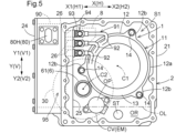
図3及び図5に示すように、車両用駆動装置100は、回転電機1と、一対の車輪W(図1参照)にそれぞれ駆動連結される一対の出力部材6と、回転電機1と一対の出力部材6との間で駆動力を伝達する伝達機構3と、オイルポンプOPと、ケース2と、を備えている。ケース2は、回転電機1、伝達機構3、及び、オイルポンプOPを収容する。本実施形態では、車両用駆動装置100は、ケース2に収容されて回転電機1を駆動制御するインバータ装置90を更に備えている。ケース2は、一対の出力部材6も収容している。
As shown in Figures 3 and 5, the
一対の出力部材6の一方である第1出力部材61は、一対の車輪Wの一方である第1車輪W1に駆動連結され、一対の出力部材6の他方である第2出力部材62は、一対の車輪Wの他方である第2車輪W2に駆動連結される。図1に示すように、車両用駆動装置100が搭載される車両200は、第1車輪W1と一体的に回転する第1ドライブシャフト63と、第2車輪W2と一体的に回転する第2ドライブシャフト64と、を備えている。第1ドライブシャフト63は、例えば等速ジョイントを介して第1車輪W1に連結され、第2ドライブシャフト64は、例えば等速ジョイントを介して第2車輪W2に連結される。そして、第1出力部材61は、第1ドライブシャフト63と一体的に回転するように第1ドライブシャフト63に連結され、第2出力部材62は、第2ドライブシャフト64と一体的に回転するように第2ドライブシャフト64に連結される。The
車両用駆動装置100は、回転電機1の出力トルクを、一対の出力部材6を介して一対の車輪Wに伝達させて、車両用駆動装置100が搭載された車両200を走行させる。すなわち、回転電機1は、一対の車輪Wの駆動力源である。一対の車輪Wは、車両200における左右一対の車輪(例えば、左右一対の前輪、又は左右一対の後輪)である。本実施形態では、回転電機1は、3相交流(多相交流の一例)で駆動される交流回転電機である。回転電機1は、直流電力と交流電力との間の電力変換を行うインバータ装置90を介して、バッテリやキャパシタ等の蓄電装置と電気的に接続されており、蓄電装置から電力の供給を受けて力行し、或いは、車両200の慣性力等により発電した電力を蓄電装置に供給して蓄電させる。The
図3に示すように、回転電機1と一対の出力部材6とは、互いに平行な2つの軸(具体的には、第1軸心C1及び第2軸心C2)に分かれて配置されている。具体的には、回転電機1が、第1軸心C1上に配置され、一対の出力部材6が、第1軸心C1とは異なる第2軸心C2上に配置されている。伝達機構3は、一対の出力部材6に駆動連結される出力ギヤ30を、一対の出力部材6と同軸に(すなわち、第2軸心C2上に)備えている。As shown in FIG. 3, the rotating
図1に示すように、車両用駆動装置100は、軸方向Aが車両左右方向に沿う向きで車両200に搭載される。軸方向Aは、第1軸心C1及び第2軸心C2に平行な方向、言い換えれば、第1軸心C1及び第2軸心C2の間で共通する軸方向である。すなわち、軸方向Aは、回転電機1の回転軸心が延びる方向であり、一対の出力部材6の回転軸心が延びる方向でもある。ここで、軸方向Aの一方側を軸方向第1側A1とし、軸方向Aの他方側(軸方向Aにおける軸方向第1側A1とは反対側)を軸方向第2側A2とする。軸方向第1側A1は、軸方向Aにおける伝達機構3に対して回転電機1が配置される側である。図3に示すように、第1出力部材61は、一対の出力部材6のうちの軸方向第1側A1に配置される方の出力部材6であり、第2出力部材62は、一対の出力部材6のうちの軸方向第2側A2に配置される方の出力部材6である。As shown in FIG. 1, the
図1に示すように、本実施形態では、車両用駆動装置100は、軸方向第1側A1が車両右側となり、軸方向第2側A2が車両左側となる向きで、車両200に搭載される。よって、第1出力部材61が駆動連結される第1車輪W1は、右輪であり、第2出力部材62が駆動連結される第2車輪W2は、左輪である。図1では、車両用駆動装置100が、左右一対の前輪を駆動する前輪駆動方式の駆動装置である場合を想定している。よって、図1に示す例では、第1車輪W1は右前輪であり、第2車輪W2は左前輪である。As shown in FIG. 1, in this embodiment, the
図3に示すように、回転電機1は、ロータ10及びステータ11を備えている。ステータ11は、ケース2に固定され、ロータ10は、ステータ11に対して回転可能にケース2に支持されている。本実施形態では、ステータ11は、締結ボルト等の締結部材14を用いてケース2に固定されている。また、本実施形態では、回転電機1は、インナロータ型の回転電機であり、ロータ10は、ステータ11に対して径方向の内側に、径方向に沿う径方向視でステータ11と重複するように配置されている。ここでの径方向は、第1軸心C1を基準とする径方向、言い換えれば、回転電機1の回転軸心を基準とする径方向である。As shown in FIG. 3, the rotating
ステータ11は、ステータコア12と、ステータコア12から軸方向Aに突出するコイルエンド部13と、を備えている。ステータコア12にはコイルが巻装されており、コイルにおけるステータコア12から軸方向Aに突出する部分がコイルエンド部13を形成している。コイルエンド部13は、ステータコア12に対して軸方向Aの両側に形成されている。図5に示すように、本実施形態では、ステータコア12は、軸方向Aに延びる円筒状に形成された本体部12aに加えて、本体部12aに対して径方向(第1軸心C1を基準とする径方向)の外側に突出するように形成された突出部12bを備えている。突出部12bには、ステータコア12をケース2に固定するための締結部材14が挿通される挿通孔が形成されている。The
図3に示すように、伝達機構3は、回転電機1に駆動連結される入力部材16を、回転電機1と同軸に(すなわち、第1軸心C1上に)備えている。本実施形態では、入力部材16は、ロータ10と一体的に回転するようにロータ10に連結されている。図3に示す例では、車両用駆動装置100は、ロータ10が固定されるロータ軸15を備えており、入力部材16は、ロータ軸15と一体的に回転するようにロータ軸15に連結されている。具体的には、入力部材16における軸方向第1側A1の部分が、ロータ軸15における軸方向第2側A2の部分に連結(ここでは、スプライン連結)されている。このような構成とは異なり、車両用駆動装置100がロータ軸15を備えず、ロータ10が入力部材16(具体的には、入力部材16における軸方向第1側A1の部分)に固定される構成とすることもできる。As shown in FIG. 3, the transmission mechanism 3 includes an
図3に示すように、本実施形態では、伝達機構3は、差動歯車機構5を備えている。差動歯車機構5は、回転電機1の側から伝達される駆動力を、一対の出力部材6に分配する。本実施形態では、差動歯車機構5は、一対の出力部材6と同軸に(すなわち、第2軸心C2上に)配置されており、回転電機1の側から出力ギヤ30に伝達される駆動力を一対の出力部材6に分配する。すなわち、本実施形態では、出力ギヤ30は、差動歯車機構5を介して、一対の出力部材6の双方に駆動連結されている。本実施形態では、差動歯車機構5は、傘歯車式の差動歯車機構であり、出力ギヤ30は、差動歯車機構5が備える差動ケース部50と一体的に回転するように当該差動ケース部50に連結されている。差動ケース部50には、第1サイドギヤ51と第2サイドギヤ52とが収容されている。そして、差動歯車機構5は、出力ギヤ30の回転を、第1サイドギヤ51と第2サイドギヤ52とに分配する。差動歯車機構5は、回転電機1に対して軸方向第2側A2に配置されている。As shown in FIG. 3, in this embodiment, the transmission mechanism 3 includes a differential gear mechanism 5. The differential gear mechanism 5 distributes the driving force transmitted from the rotating
第1サイドギヤ51は、第1出力部材61と一体的に回転し、第2サイドギヤ52は、第2出力部材62と一体的に回転する。本実施形態では、第1サイドギヤ51は、第1出力部材61を構成する部材(ここでは、軸部材)とは別の部材に形成されており、第1出力部材61と一体的に回転するように第1出力部材61に連結(ここでは、スプライン連結)されている。第1出力部材61における少なくとも軸方向第1側A1の部分は、軸方向Aに延びる筒状(具体的には、円筒状)に形成されており、第1ドライブシャフト63(図1参照)は、第1出力部材61の内部(内周面に囲まれる空間)に、軸方向第1側A1から挿入される。また、本実施形態では、第2サイドギヤ52は、第2出力部材62を構成する部材(ここでは、軸部材)に形成されている。具体的には、第2サイドギヤ52は、第2出力部材62における軸方向第1側A1の端部に形成されている。第2出力部材62における少なくとも軸方向第2側A2の部分は、軸方向Aに延びる筒状(具体的には、円筒状)に形成されており、第2ドライブシャフト64(図1参照)は、第2出力部材62の内部(内周面に囲まれる空間)に、軸方向第2側A2から挿入される。The
図3に示すように、本実施形態では、伝達機構3は、回転電機1と出力ギヤ30との間の動力伝達経路に、回転電機1及び出力ギヤ30とは別軸に配置されたカウンタギヤ機構4を備えている。カウンタギヤ機構4は、第1軸心C1及び第2軸心C2とは異なる第3軸心C3上に配置されている。第3軸心C3は、第1軸心C1及び第2軸心C2に平行な軸心である。本実施形態では、カウンタギヤ機構4は、入力部材16と一体的に回転する入力ギヤ17に噛み合うカウンタ入力ギヤ40aと、出力ギヤ30に噛み合うカウンタ出力ギヤ40bと、カウンタ入力ギヤ40aとカウンタ出力ギヤ40bとを連結するカウンタ軸40と、を備えている。入力ギヤ17は、回転電機1に対して軸方向第2側A2に配置され、カウンタギヤ機構4は、回転電機1に対して軸方向第2側A2に配置されている。本実施形態では、カウンタ入力ギヤ40aは、カウンタ出力ギヤ40bに対して軸方向第2側A2に配置されている。As shown in FIG. 3, in this embodiment, the transmission mechanism 3 includes a
本実施形態では、カウンタ入力ギヤ40aは入力ギヤ17よりも大径に形成され、カウンタ出力ギヤ40bは出力ギヤ30よりも小径に形成されている。よって、入力部材16の回転は、入力ギヤ17とカウンタ入力ギヤ40aとの歯数比に応じて減速されると共に、カウンタ出力ギヤ40bと出力ギヤ30との歯数比に応じて更に減速されて(すなわち、二段減速されて)、出力ギヤ30に伝達される。In this embodiment, the
図2及び図3に示すように、本実施形態では、ケース2は、第1ケース部21と、第2ケース部22と、第3ケース部23と、を備えている。第2ケース部22は、第1ケース部21の軸方向第2側A2に接合され、第3ケース部23は、第1ケース部21の軸方向第1側A1に接合されている。第1ケース部21と第3ケース部23とに囲まれる空間に回転電機1が収容され、第1ケース部21と第2ケース部22とに囲まれる空間に伝達機構3が収容されている。このように、ケース2は、回転電機1を収容する回転電機収容室S1を備えている。ケース2は、伝達機構3を収容する伝達機構収容室S3を更に備えている。収容室は、収容対象物が収容される収容空間を形成している。一対の出力部材6の少なくとも一方は、回転電機収容室S1と連通した空間に配置されている。本実施形態では、第1出力部材61が、回転電機収容室S1と連通した空間に収容されている。具体的には、第1出力部材61における少なくとも回転電機1と軸方向Aに重複する部分(軸方向Aの配置領域が重複する部分)が、回転電機収容室S1と連通した空間に収容されている。このように、本実施形態では、回転電機1と第1出力部材61とが、ケース2が備える共通の収容室(具体的には、回転電機収容室S1を含む収容室)に収容されている。2 and 3, in this embodiment, the
本実施形態では、ケース2は、更に、インバータ装置90が収容されるインバータ収容室S2を備えている。具体的には、ケース2は、第1ケース部21に接合される第4ケース部24を備えており、第1ケース部21と第4ケース部24とに囲まれる空間(インバータ収容室S2)にインバータ装置90が収容されている。インバータ装置90は、ボルト等によってケース2に固定された状態で、インバータ収容室S2に収容されている。本実施形態では、インバータ収容室S2は、後述する第1方向第1側X1(図2参照)に開口するように第1ケース部21に形成されており、第4ケース部24は、当該開口部を塞ぐように第1ケース部21に接合されている。詳細は省略するが、インバータ装置90は、インバータ回路を構成する複数のスイッチング素子を備えたスイッチング素子ユニット(パワーモジュール)と、インバータ回路を制御する制御装置が実装された制御基板と、インバータ回路の直流側の正負両極間電圧を平滑化する平滑コンデンサと、を備えており、これらのスイッチング素子ユニット、制御基板、及び平滑コンデンサが、インバータ収容室S2に収容されている。このように、本実施形態では、回転電機収容室S1とインバータ収容室S2とが1つのケース2に一体的に形成されている。In this embodiment, the
図3に示すように、ケース2は、回転電機収容室S1とインバータ収容室S2とを区画する隔壁25(区画壁)を備えている。本実施形態では、回転電機収容室S1とインバータ収容室S2とが、ケース2(ここでは、第1ケース部21)に一体的に形成されている。具体的には、回転電機収容室S1とインバータ収容室S2とは、一部材(例えば、ダイカスト法によって形成された、材質を共通とする1つの部材)に形成されている。そして、本実施形態では、回転電機収容室S1とインバータ収容室S2とは、1枚の隔壁25によって区画されている。As shown in FIG. 3, the
図2に示すように、本実施形態では、ケース2には、ケース2の外部に配置されたケーブル7(図6参照)とインバータ装置90とを電気的に接続するためのコネクタ80が設けられている。なお、図6では、ケーブル7を簡略化して示している。図4~図6に示すように、コネクタ80は、低電圧コネクタ80Lと、低電圧コネクタ80Lよりも高い電圧の電力を中継する高電圧コネクタ80Hと、を含んでいる。インバータ装置90が備える制御基板に電力を供給するための電源線(低電圧ケーブル7Lの一例)や、当該制御基板に制御信号を伝達するための信号線(低電圧ケーブル7Lの一例)が、低電圧コネクタ80Lに接続される。また、インバータ装置90が備えるインバータ回路に電力を供給するための電源線(高電圧ケーブル7Hの一例)が、高電圧コネクタ80Hに接続される。As shown in FIG. 2, in this embodiment, the
ここで、図4に示すように、軸方向Aに沿う軸方向視(言い換えれば、第2軸心C2に沿う軸方向視)で回転電機1とインバータ装置90とが並ぶ方向を第1方向Xとし、軸方向A及び第1方向Xの双方に直交する方向を第2方向Yとする。本実施形態では、第1方向Xは後述する幅方向Hと同じ方向であり、第2方向Yは上下方向Vと同じ方向である。また、第1方向Xの一方側を第1方向第1側X1とし、第1方向Xの他方側(第1方向Xにおける第1方向第1側X1とは反対側)を第1方向第2側X2とし、第2方向Yの一方側を第2方向第1側Y1とし、第2方向Yの他方側(第2方向Yにおける第2方向第1側Y1とは反対側)を第2方向第2側Y2とする。第1方向第1側X1は、第1方向Xにおける回転電機1に対してインバータ装置90が配置される側である。なお、図4では、ステータコア12(具体的には、上述した本体部12a)の外周面を破線で示し、各ギヤの歯底円及び歯先円を一点鎖線で示し、第1出力部材61の外周面(具体的には、第1出力部材61における回転電機1とインバータ装置90との第1方向Xの間に挟まれて配置される部分の外周面)を実線で示している。4, the direction in which the rotating
本実施形態では、車両用駆動装置100は、第2方向第1側Y1が上側V1となり、第2方向第2側Y2が下側V2となる向きで、車両200に搭載される。また、本実施形態では、車両用駆動装置100は、第1方向第2側X2が前側L1(車両前後方向Lの前側)となり、第1方向第1側X1が後側L2(車両前後方向Lの後側)となる向きで、車両200に搭載される。図1に示すように、本実施形態では、車両用駆動装置100は、車両200における車両前後方向Lの中央部よりも前側L1に搭載される。そのため、第1方向Xにおける回転電機1に対してインバータ装置90が配置される側であって、本実施形態では後側L2となる第1方向第1側X1は、車両前後方向Lの中央側となる。よって、本実施形態では、車両搭載状態において、インバータ装置90は、回転電機1よりも車両前後方向Lの中央側に配置される。なお、車両用駆動装置100が、車両200における車両前後方向Lの中央部よりも後側L2に搭載される場合には、車両用駆動装置100を、第1方向第2側X2が後側L2となり、第1方向第1側X1が前側L1となる向きで車両200に搭載することで、インバータ装置90が回転電機1よりも車両前後方向Lの中央側に配置される構成とすることができる。このように車両用駆動装置100が車両200における車両前後方向Lの中央部よりも後側L2に搭載される場合、車両用駆動装置100により駆動される一対の車輪Wは、例えば左右一対の後輪とされる。In this embodiment, the
車両200が、左右一対の前輪及び左右一対の後輪を備える場合に、左右一対の前輪及び左右一対の後輪のうちの車両用駆動装置100により駆動されない方(図1に示す例では、左右一対の後輪)が、車両用駆動装置100以外の駆動装置により駆動される構成とすることもできる。車両用駆動装置100以外の駆動装置は、例えば、内燃機関(回転電機以外の駆動力源の一例)の出力トルクを駆動対象の一対の車輪に伝達させる構成の駆動装置、回転電機(車両用駆動装置100が備える回転電機1とは別の回転電機)の出力トルクを駆動対象の一対の車輪に伝達させる構成の駆動装置、或いは、内燃機関及び回転電機(車両用駆動装置100が備える回転電機1とは別の回転電機)の双方の出力トルクを駆動対象の一対の車輪に伝達させる構成の駆動装置とされる。車両用駆動装置100以外の駆動装置を、車両用駆動装置100と同じ構成の駆動装置とすることもできる。When the
ここで、上下方向Vに沿う上下方向視で第1軸心C1に直交する方向を幅方向Hとする。本実施形態では、第1軸心C1に直交する水平方向(すなわち、軸方向A及び上下方向Vに直交する方向)を幅方向Hとする。図4に示すように、本実施形態では、回転電機1とインバータ装置90とは、それぞれの上下方向Vの配置領域が重複するように配置されている。そのため、一例として、幅方向Hを、第1方向Xとして定義することができる。この場合、図4に示すように、第2方向Yは上下方向Vに平行な方向となる。また、別例として、軸方向視で、第1軸心C1とインバータ装置90の中心90aとを通る仮想直線Eに沿う方向を、第1方向Xとして定義することもできる。ここで、軸方向視でのインバータ装置90の中心90aは、インバータ装置90の軸方向視での外形(外縁)を成す図形の重心とすることができる。図4に示す例では、インバータ装置90の軸方向視での外形を成す図形は、長方形状(ここでは、第2方向Yに長い長方形状、言い換えれば、上下方向Vに長い長方形状)の図形であり、この長方形の重心(具体的には、対角線の交点)を軸方向視でのインバータ装置90の中心90aとすることができる。図4に示す例では、幅方向Hと、軸方向視で仮想直線Eに沿う方向とは、互いに平行な方向となる。すなわち、図4に示す例では、上記2つの定義のいずれによっても、第1方向Xは同じ方向に定義される。ここで、幅方向Hの一方側(本実施形態では、第1方向第1側X1と一致)を幅方向第1側H1とし、幅方向第1側H1とは反対側(本実施形態では、第1方向第2側X2と一致)を幅方向第2側H2とする。Here, the direction perpendicular to the first axis C1 in the vertical direction V is defined as the width direction H. In this embodiment, the horizontal direction perpendicular to the first axis C1 (i.e., the direction perpendicular to the axial direction A and the vertical direction V) is defined as the width direction H. As shown in FIG. 4, in this embodiment, the rotating
図4に示すように、本実施形態では、第1出力部材61は、回転電機1及びインバータ装置90の双方が配置される第2方向Yの位置において、回転電機1とインバータ装置90との第1方向Xの間に挟まれて配置されている。第1出力部材61における回転電機1とインバータ装置90との第1方向Xの間に挟まれる部分は、回転電機1と軸方向Aの配置領域が重複すると共に、インバータ装置90と軸方向Aの配置領域が重複するように配置されている(図3参照)。そして、図4に示すように、出力ギヤ30は、軸方向視で、回転電機1とインバータ装置90とのそれぞれと重複するように配置されている。具体的には、出力ギヤ30における第1方向第2側X2の部分が軸方向視で回転電機1と重複し、出力ギヤ30における第1方向第1側X1の部分が軸方向視でインバータ装置90と重複するように、出力ギヤ30が配置されている。図3に示すように、出力ギヤ30は、回転電機1及びインバータ装置90に対して軸方向Aの一方側(具体的には、軸方向第2側A2)に配置されている。そして、回転電機1及びインバータ装置90は、それぞれの軸方向Aの配置領域が重複するように配置されている。本実施形態では、車両搭載状態において、インバータ装置90の少なくとも一部(図4に示す例では、一部のみ)が、第2軸心C2よりも下側V2に配置される。なお、車両搭載状態において、インバータ装置90の全体が、第2軸心C2よりも上側V1に配置される構成とすることもできる。As shown in FIG. 4, in this embodiment, the
上記のように、本実施形態では、出力ギヤ30は、軸方向視で、回転電機1とインバータ装置90とのそれぞれと重複するように配置されている。そのため、図4及び図5に示すように、インバータ装置90は、軸方向視で出力ギヤ30と重複するように配置された部分である重複部分95を備えている。そして、コネクタ80(具体的には、低電圧コネクタ80L及び高電圧コネクタ80H)は、ケース2における、重複部分95(言い換えれば、軸方向視で重複部分95と重複するケース2の部分)よりも上側V1であって、軸方向視でインバータ装置90と重複する領域(以下、「対象領域」という)に配置されている。図2に示すように、コネクタ80は、ケース2における軸方向Aの端面に配置されている。As described above, in this embodiment, the
図4に示すように、本実施形態では、一例として、インバータ装置90は、第2軸心C2よりも下側V2から出力ギヤ30の上端よりも上側V1までの上下方向Vの範囲に亘って配置されている。インバータ装置90がこのように配置されるため、ケース2における軸方向視でインバータ装置90と重複する領域における、重複部分95よりも上側V1の部分が、デッドスペースとなりやすい。この車両用駆動装置100では、コネクタ80が上記の対象領域に配置されるため、デッドスペースとなりやすい領域を有効に利用してコネクタ80を配置することが可能となっている。As shown in FIG. 4, in this embodiment, as an example, the
図4~図6に示すように、本実施形態では、一例として、低電圧コネクタ80Lと高電圧コネクタ80Hとが、インバータ装置90を挟んで軸方向Aの互いに反対側に配置されている。具体的には、低電圧コネクタ80Lが、ケース2における軸方向第2側A2の端面に配置され(図2参照)、高電圧コネクタ80Hが、ケース2における軸方向第1側A1の端面に配置されている。このような構成とは異なり、低電圧コネクタ80Lと高電圧コネクタ80Hとがインバータ装置90に対して軸方向Aの同じ側に配置される場合、低電圧コネクタ80Lと高電圧コネクタ80Hとの距離が短くなりやすく、高電圧コネクタ80Hが中継する電圧の影響によって、低電圧コネクタ80Lが中継する電圧(例えば、制御信号)にノイズがのる可能性がある。これに対して、上記のように低電圧コネクタ80Lと高電圧コネクタ80Hとをインバータ装置90を挟んで軸方向Aの互いに反対側に配置することで、低電圧コネクタ80Lと高電圧コネクタ80Hとの距離を長く確保して、上記のノイズの問題を発生し難くすることができる。4 to 6, in this embodiment, as an example, the low-
本実施形態では、コネクタ80は、ケース2における軸方向Aの端面に配置され、車両用駆動装置100は、軸方向Aが車両左右方向に沿う向きで車両200に搭載される。このように、コネクタ80を、ケース2における車両前後方向L(前側L1又は後側L2)の端面やケース2における下側V2の端面ではなく、ケース2における車両左右方向(左側又は右側)の端面に配置することで、車両200の衝突時の衝突荷重の影響を受けにくい位置にコネクタ80を配置することができる。また、例えば、車両用駆動装置100を車両200の後部に搭載する場合には、上下方向Vにおける搭載制約が厳しくなりやすいが、コネクタ80を、ケース2における上側V1の端面ではなく、ケース2における車両左右方向(左側又は右側)の端面に配置することで、車両用駆動装置100の上下方向Vの寸法を小さく抑えて、車両用駆動装置100の車両200への搭載性を確保しやすくなる。In this embodiment, the
図4に示すように、回転電機1の回転軸心である第1軸心C1、出力ギヤ30の回転軸心(言い換えれば、一対の出力部材6の回転軸心)である第2軸心C2、及び、カウンタギヤ機構4の回転軸心である第3軸心C3は、インバータ装置90の上下方向Vの配置領域内に配置されている。本実施形態では、第3軸心C3は、軸方向視で、第2軸心C2に対して第1方向Xにおけるインバータ装置90側とは反対側(すなわち、第1方向第2側X2)に配置されている。本実施形態では、第3軸心C3は、軸方向視で、第1軸心C1に対しても第1方向第2側X2に配置されている。また、本実施形態では、第2軸心C2と第3軸心C3とは、軸方向視で、第1軸心C1に対して第2方向Yにおける同じ側(ここでは、第2方向第2側Y2)に配置されている。すなわち、第2軸心C2は、軸方向視で、第1軸心C1に対して第2方向第2側Y2に配置されている。ここでは、第2軸心C2は、車両搭載状態において、軸方向視で、仮想直線Eに対して下側V2に配置される。また、第3軸心C3は、軸方向視で、第1軸心C1に対して第2方向第2側Y2に配置されている。ここでは、第3軸心C3は、車両搭載状態において、軸方向視で、仮想直線Eに対して下側V2に配置される。また、本実施形態では、第3軸心C3は、軸方向視で、第1軸心C1と第2軸心C2とを通る仮想直線に対してインバータ装置90の中心90a側とは反対側に配置されている。As shown in FIG. 4, the first axis C1, which is the rotation axis of the rotating
図4に示す例では、第2軸心C2とインバータ装置90との双方が配置された上下方向Vの領域において、第2軸心C2は、インバータ装置90に対して幅方向第2側H2に配置されている。また、回転電機1の幅方向第2側H2の端部は、第2軸心C2よりも幅方向第2側H2に配置されている。そして、第3軸心C3は、回転電機1(例えば、ステータコア12又は本体部12a)の幅方向第2側H2の端部よりも幅方向第1側H1に配置されている。このように第2軸心C2及び第3軸心C3が配置されるため、回転電機1の幅方向第2側H2の端部とインバータ装置90との幅方向Hの間に全体又は大部分が収まるように、出力ギヤ30及びカウンタギヤ機構4を配置することができる。よって、車両用駆動装置100の幅方向Hにおける小型化を図ることができる。図4に示す例では、回転電機1の幅方向第2側H2の端部とインバータ装置90の幅方向第1側H1の端部との幅方向Hの間に、出力ギヤ30の全体及びカウンタギヤ機構4の全体が配置されている。In the example shown in FIG. 4, in the region of the vertical direction V where both the second axis C2 and the
図4に示す例では、第3軸心C3は、第2軸心C2よりも幅方向第2側H2に配置されている。また、回転電機1(具体的には、ステータコア12)は、カウンタギヤ機構4よりも大径に形成されており、第1軸心C1は、第3軸心C3よりも幅方向第1側H1に配置されている。そして、カウンタギヤ機構4の全体が、回転電機1(例えば、ステータコア12又は本体部12a)の幅方向第2側H2の端部よりも幅方向第1側H1に配置されている。このように回転電機1及びカウンタギヤ機構4を配置することで、カウンタギヤ機構4が回転電機1に対して幅方向第2側H2に突出しない範囲内で、回転電機1を幅方向Hでインバータ装置90の側に寄せて配置することができる。よって、車両用駆動装置100の幅方向Hにおける小型化を図ることができる。図4に示す例では、第1軸心C1は、第2軸心C2よりも幅方向第2側H2に配置されている。In the example shown in FIG. 4, the third axis C3 is disposed on the second width direction side H2 from the second axis C2. The rotating electric machine 1 (specifically, the stator core 12) is formed with a larger diameter than the
また、図4に示す例では、第2軸心C2及び第3軸心C3は、第1軸心C1よりも下側V2に配置されている。後述するように、油(潤滑や冷却のための油)を貯留する油貯留空間ORがケース2の下部に形成されており(図4参照)、このように第2軸心C2及び第3軸心C3を配置することで、油貯留空間ORに貯留された油を、第2軸心C2に配置された出力ギヤ30と、第3軸心C3に配置されたギヤ(本例では、カウンタ入力ギヤ40a)との双方によって掻き揚げる構成とすることができる。よって、潤滑性能や冷却性能の向上を図ることができる。図4に示す例では、出力ギヤ30の下端部が、回転電機1の下端部及びカウンタギヤ機構4の下端部のいずれよりも下側V2に配置されている。これにより、出力ギヤ30による油の掻き揚げを効率的に行うことができる。
In the example shown in FIG. 4, the second axis C2 and the third axis C3 are arranged on the lower side V2 of the first axis C1. As described later, an oil storage space OR for storing oil (oil for lubrication and cooling) is formed in the lower part of the case 2 (see FIG. 4). By arranging the second axis C2 and the third axis C3 in this manner, the oil stored in the oil storage space OR can be scooped up by both the
図4に示す例では、インバータ装置90は、第2軸心C2よりも下側V2から回転電機1(例えば、ステータコア12又は本体部12a)の上端よりも上側V1までの上下方向Vの範囲に亘って配置されている。このようにインバータ装置90が配置される場合、インバータ装置90の上下方向Vの配置領域内に全体又は大部分が収まるように、回転電機1を配置することができる。よって、車両用駆動装置100の上下方向Vにおける小型化を図ることができる。In the example shown in Figure 4, the
図5に示すように、ケース2は、回転電機収容室S1の下部に設けられた油貯留空間ORを備えている。油貯留空間ORは、回転電機収容室S1における油を貯留するための空間である。例えば、回転電機収容室S1における油面OLよりも下側V2になる場合がある部分(言い換えれば、回転電機収容室S1における、油面OLの変化範囲における最も高い油面OLよりも下側V2の部分)を、油貯留空間ORと定義することができる。油貯留空間ORは、回転電機1よりも下側V2に設けられても、回転電機1の一部が油に浸かるように設けられてもよい。本実施形態では、少なくとも油面OLの変化範囲における最も低い油面OLが回転電機1よりも下側V2に配置されるように、油貯留空間ORが設けられている。油貯留空間ORは、少なくとも回転電機収容室S1に設けられる。本実施形態では、図4に示すように、油貯留空間ORは、伝達機構収容室S3(具体的には、伝達機構収容室S3の下部)にも設けられている。すなわち、油貯留空間ORは、回転電機収容室S1と伝達機構収容室S3との双方に亘って設けられている。図示は省略するが、回転電機収容室S1と伝達機構収容室S3とを連通する連通孔が、回転電機収容室S1と伝達機構収容室S3とを区画する中間壁28(図3参照)に形成されている。この連通孔を介して、回転電機収容室S1と伝達機構収容室S3との間で油が流動可能となっている。このように、油貯留空間ORを、回転電機収容室S1と伝達機構収容室S3との双方に亘って設けることで、油貯留空間ORの油面が高くなり過ぎることを回避しつつケース2内の油量を十分に確保することが容易となる。よって、伝達機構3を構成する各ギヤによる油の攪拌を少なく抑えて、当該油の攪拌による駆動力の損失を低減しつつ、潤滑又は冷却のために必要な量の油を車両用駆動装置100の各部に適切に供給することができる。As shown in FIG. 5, the
図5に示すように、ケース2の内部の油貯留空間OR内(具体的には、回転電機収容室S1の下部の油貯留空間OR内)に、回転電機1に冷却用の油を供給するオイルポンプOPが配置されている。ここで、ある部材の配置に関して「油貯留空間OR内」とは、当該部材の少なくとも一部が油貯留空間OR内に配置されることを意味する。オイルポンプOPは、油貯留空間ORに貯留された油を吸引する。オイルポンプOPは、少なくとも回転電機1(具体的には、コイルエンド部13等の冷却対象部位)に冷却用の油を供給する。オイルポンプOPが、更に、ギヤや軸受等に潤滑用の油を供給する構成としてもよい。図6に示すように、本実施形態では、オイルポンプOPは、専用の電動モータEMにより駆動される電動オイルポンプである。具体的には、オイルポンプOPは、ポンプ室を有するポンプ部を備え、ポンプ部に収容されたポンプロータが電動モータEMにより駆動される。ポンプ部に加えて電動モータEMを、オイルポンプOPの構成要素とみなしてもよい。電動モータEMは、オイルポンプOPと同様に、油貯留空間OR内に配置されている。図5に示すように、電動モータEMは、カバーCVを備えており、カバーCVは、油貯留空間OR内に配置されている。電動モータEMは、ロータ及びステータの収容空間を形成するハウジングを備えており、カバーCVは当該ハウジングの少なくとも一部を構成している。カバーCVは、例えば、上記ハウジングの周壁部を形成する部材とされ、或いは、上記ハウジングの端壁部(例えば、軸方向第1側A1の端壁部)を形成する部材とされる。As shown in FIG. 5, an oil pump OP that supplies cooling oil to the rotating
図5に示すように、オイルポンプOPは、油貯留空間OR内であって、軸方向視で出力ギヤ30と重複するように配置されている。具体的には、オイルポンプOPは、油貯留空間OR内であって、第1軸心C1及び第2軸心C2よりも下側V2、且つ、軸方向視で出力ギヤ30と重複する位置に配置されている。このようにオイルポンプOPを配置することで、油貯留空間ORにおける軸方向視で出力ギヤ30と重複する空間をオイルポンプOPの配置空間として有効に利用して、車両用駆動装置100の小型化を図ることができる。オイルポンプOPの全体又は大部分が、軸方向視で出力ギヤ30と重複するように配置されていると好適である。なお、オイルポンプOPは、軸方向視で回転電機1と重複しないように配置されている。As shown in FIG. 5, the oil pump OP is arranged in the oil storage space OR so as to overlap with the
図5に示すように、車両用駆動装置100は、オイルポンプOPが吸引する油を濾過するストレーナSTを更に備えている。本実施形態では、第2軸心C2及びオイルポンプOPは、第1軸心C1に対して幅方向第1側H1に配置されている。そして、図5及び図6に示すように、ストレーナSTは、油貯留空間OR内であって、回転電機1よりも下側V2且つオイルポンプOPに対して幅方向第2側H2であり、且つ、上下方向視で回転電機1と重複する位置に配置されている。本例では、図5に示すように、ストレーナSTは、上下方向視で回転電機1の回転軸心(第1軸心C1)と重複する位置に配置されている。また、本例では、図6に示すように、ストレーナSTにおける軸方向第1側A1の部分が、上下方向視で回転電機1における軸方向第2側A2の部分と重複するように配置されている。As shown in FIG. 5, the
図5に示すように、本実施形態では、オイルポンプOPの上下方向Vにおける配置領域の全体が、出力ギヤ30の上下方向Vにおける配置領域に収まっている。また、本実施形態では、オイルポンプOPの上下方向Vにおける配置領域が、インバータ装置90の上下方向Vにおける配置領域と重複している。図5に示す例では、オイルポンプOPの上側V1の部分とインバータ装置90の下側V2の部分とが上下方向Vの同じ領域に配置されている。As shown in Figure 5, in this embodiment, the entire arrangement area of the oil pump OP in the vertical direction V is contained within the arrangement area of the
図5に示す例では、オイルポンプOPは、第1軸心C1と第2軸心C2との幅方向Hの間であって、第1軸心C1及び第2軸心C2よりも下側V2に配置されている。このようにオイルポンプOPを第1軸心C1と第2軸心C2との幅方向Hの間に配置することで、例えば、オイルポンプOPやそれに接続されるストレーナSTを、エア吸いの発生を抑制しやすい幅方向Hの中央部分やその近くに配置しやすくなる。また、オイルポンプOPを、第1軸心C1及び第2軸心C2よりも下側V2に配置することで、ケース2の下部に形成された油貯留空間ORの近くにオイルポンプOPを配置して、油の吸引抵抗を低く抑えやすくなる。In the example shown in FIG. 5, the oil pump OP is disposed between the first axis C1 and the second axis C2 in the width direction H, and on the lower side V2 of the first axis C1 and the second axis C2. By disposing the oil pump OP between the first axis C1 and the second axis C2 in the width direction H in this manner, for example, it becomes easier to dispose the oil pump OP and the strainer ST connected thereto in or near the center of the width direction H, where it is easier to suppress the occurrence of air suction. In addition, by disposing the oil pump OP on the lower side V2 of the first axis C1 and the second axis C2, it becomes easier to dispose the oil pump OP near the oil storage space OR formed in the lower part of the
図4~図6に示す例では、オイルポンプOPから吐出された油は、オイルクーラ9(図4及び図6参照)を通って回転電機1に供給される。オイルクーラ9は、油と冷媒との間での熱交換によって油を冷却する。本例では、オイルクーラ9は、冷媒として冷却水を用いる水冷式のオイルクーラであり、図4及び図6に示すように、オイルクーラ9には、冷却水をオイルクーラ9に導入するための第1接続口P1と、冷却水をオイルクーラ9から排出するための第1接続口P1とが設けられている。
In the example shown in Figures 4 to 6, oil discharged from the oil pump OP is supplied to the rotating
本例では、第1接続口P1は、ケース2における上側V1の外面に配置されている。また、本例では、インバータ装置90には、当該インバータ装置90を冷却するための冷却水路が設けられている。そして、図6に示すように、この冷却水路に冷却水を導入するための第2接続口P2と、この冷却水路から冷却水を排出するための第2接続口P2とが、ケース2における上側V1の外面に配置されている。このように、第1接続口P1と第2接続口P2とをケース2における同じ外面(同じ側の外面)に配置することで、これらの第1接続口P1や第2接続口P2に対する配管部材(ホース等)の接続作業が容易になる。また、配管部材の長さを短く抑えてコストの低減を図ることも可能である。In this example, the first connection port P1 is arranged on the outer surface of the upper side V1 of the
図6に示す例では、オイルクーラ9は、平面視(上下方向Vに沿う方向視)で、回転電機収容室S1と伝達機構収容室S3との境界部を跨ぐように配置されている。本例では、ケース2における上側V1の外面に、下側V2に窪む凹部が形成されている。この凹部は、ケース2の内部空間における空きスペースを利用して形成されており、この凹部にオイルクーラ9が配置されている(図4参照)。そのため、オイルクーラ9は、回転電機収容室S1(具体的には、回転電機収容室S1における上記凹部に対して軸方向第1側A1の部分)と伝達機構収容室S3(具体的には、伝達機構収容室S3における上記凹部に対して軸方向第2側A2の部分)との軸方向Aの間に配置されている。このように、本実施形態では、第2軸心C2は、第1軸心C1よりも下側V2に配置され、オイルクーラ9は、出力ギヤ30よりも上側V1であって、上下方向視で伝達機構収容室S3と重複するように配置されている。ここでは、オイルクーラ9は、更に、上下方向視で回転電機収容室S1とも重複するように配置されている。In the example shown in FIG. 6, the
上記のように空きスペースを利用してオイルクーラ9を配置することで、車両用駆動装置100の大型化を抑制することができる。また、ケース2の下部に形成された油貯留空間ORの車両200の走行時における油面の傾きを考慮して、オイルポンプOPやストレーナSTは、図6に示す例のように軸方向Aの中央部分やその近くに配置されることが多いが、上記のようにオイルクーラ9を回転電機収容室S1と伝達機構収容室S3との軸方向Aの間に配置することで、オイルクーラ9と、オイルポンプOP及びストレーナSTとを、軸方向Aの同じ或いは近い位置に配置することができる。これにより、油路の複雑化を抑制することができる。なお、図4に示す例では、オイルクーラ9は、第1軸心C1とインバータ装置90との幅方向Hの間に配置されている。また、本実施形態では、図6に示すように、オイルクーラ9は、上下方向視でオイルポンプOPと重複するように配置されている。ここでは、オイルクーラ9における軸方向第1側A1の部分が、上下方向視でオイルポンプOPにおける軸方向第2側A2の部分と重複するように配置されている。図6では、ストレーナSTを介して油貯留空間ORからオイルポンプOPへ向かう油の流れの矢印F1で概略的に示し、オイルポンプOPからオイルクーラ9へ向かう油の流れを矢印F2で概略的に示している。図6から分かるように、本実施形態では、ストレーナSTとオイルポンプOPとを接続する油路が、中間壁28(図3参照)を利用して中間壁28の内部又は外部に形成され、オイルポンプOPとオイルクーラ9とを接続するように上下方向Vに延びる油路27が、中間壁28を利用して中間壁28の内部又は外部に形成されている。By arranging the
図4に示すように、本実施形態では、第1出力部材61は、第2方向Yに沿う方向視で、回転電機1と重複するように配置されている。すなわち、第1出力部材61は、回転電機1と第1方向Xの配置領域が重複するように配置されている。ここでは、第1出力部材61における第1方向第2側X2の部分が第2方向Yに沿う方向視で回転電機1と重複するように、第1出力部材61が配置されている。一方、本実施形態では、第1出力部材61は、第2方向Yに沿う方向視で、インバータ装置90と重複しないように配置されている。なお、図4に示す各部品の軸方向視での配置構成は一例であり、この配置構成は適宜変更することができる。例えば、図4の配置構成を第1方向Xに反転させた構成、図4の配置構成を第2方向Yに反転させた構成、或いは、図4の配置構成を第1方向X及び第2方向Yの双方に反転させた構成とすることができる。As shown in FIG. 4, in this embodiment, the
図5に示すように、回転電機1とインバータ装置90とを接続する配線91が挿通される貫通孔26が、隔壁25を貫通して形成されている。なお、図4は、車両用駆動装置100を軸方向第2側A2から見た場合の、車両用駆動装置100の各部品の軸方向視での配置関係を示しているのに対して、図5は、車両用駆動装置100を軸方向第1側A1から見た場合の、車両用駆動装置100の各部品の軸方向視での配置関係を示している。貫通孔26には、端子93を備えた端子台が取り付けられており、当該端子93を介して、コイルエンド部13から引き出された動力線92とインバータ装置90に接続された電源線(図示せず)とが電気的に接続されている。これらの電源線、端子93、及び動力線92が、回転電機1とインバータ装置90との間で電力(回転電機1を駆動するための電力や回転電機1が発電した電力)を伝達するための配線91を構成している。本実施形態では、回転電機1を駆動する交流電力の相数が“3”であることに対応して、3つの動力線92が設けられており、3つの貫通孔26が隔壁25に形成されている。As shown in FIG. 5, a through
図5に示すように、本実施形態では、車両搭載状態において、貫通孔26(ここでは、3つの全ての貫通孔26)が、第2軸心C2よりも上側V1であって回転電機1及びインバータ装置90の双方が配置される高さ(上下方向Vの位置)において、軸方向視で回転電機1とインバータ装置90との第1方向Xの間に配置される。なお、ここでは、回転電機1が配置される高さには、ステータコア12の上述した突出部12bが配置される高さを含めている。図5に示す例では、車両搭載状態において、貫通孔26(ここでは、3つの全ての貫通孔26)が、第1軸心C1よりも上側V1であって回転電機1及びインバータ装置90の双方が配置される高さにおいて、軸方向視で回転電機1とインバータ装置90との第1方向Xの間に配置される。5, in the present embodiment, in the vehicle-mounted state, the through holes 26 (here, all three through holes 26) are disposed between the rotating
図5に示す例では、ブリーザ室8が、軸方向視で配線91(具体的には、配線91における回転電機収容室S1に配置される部分)と重複する位置に形成されている。ブリーザ室8は、ケース2の内部と外部とを連通させるブリーザ装置を構成している。ブリーザ室8は、伝達機構収容室S3に比べて油の飛散の少ない回転電機収容室S1に開口するように形成されている。配線91は、油面に浸かることを極力避けるために、回転電機収容室S1における上側V1に配置されるが、回転電機収容室S1の内部には、一般に、ステータコア12の軸方向Aの長さに応じた空きスペースが、配線91に対して軸方向Aの一方側に形成される。図5に示す例では、配線91が、ステータコア12における軸方向第1側A1(図5における紙面手前側)の端部或いはその近傍に配置されているため、ステータコア12の軸方向Aの長さに応じた空きスペースが、配線91に対して軸方向第2側A2(図5における紙面奥側)に形成されている。ブリーザ室8を、軸方向視で配線91と重複する位置に設けることで、この空きスペースを有効に利用して、油の飛散し難い比較的上側V1の位置に、追加のスペースを必要とせずに或いは追加のスペースを最小限に抑えつつ、ブリーザ室8を形成することが可能となっている。In the example shown in FIG. 5, the
ところで、回転電機1とインバータ装置90とが互いに異なる方向に変位しようとした場合、配線91に荷重(例えば、引っ張り荷重)が作用して、配線91を構成する部材(バスバー等)に応力が発生したり、配線91における異なる部材同士の接続部94(図5に示す例では、動力線92と端子93とのボルトによる締結部)に荷重が加わったりするおそれがある。回転電機1とインバータ装置90との互いに異なる方向への変位は、伝達機構3による駆動力の伝達時に第1軸心C1と第2軸心C2とが互いに異なる方向に変位することで生じ得る。この点に関し、図5に示す例では、締結部材14によってケース2に固定されるステータコア12の突出部12bが、軸方向視で配線91(具体的には、接続部94)と出力部材6(具体的には、第1出力部材61)との間に配置されるように、回転電機1がケース2に固定されている。言い換えれば、接続部94と突出部12bと第1出力部材61とが軸方向視で一直線上に並ぶように、回転電機1がケース2に固定されている。このように回転電機1をケース2に固定することで、伝達機構3による駆動力の伝達時に第1軸心C1と第2軸心C2とが互いに異なる方向に変位し難くして、配線91に大きな荷重が作用し難くすることができる。However, when the rotating
図5に示す例では、軸方向視で配線91と出力部材6との間に配置される突出部12b以外に、2つの突出部12bを、ステータコア12が備えている。すなわち、ステータコア12は、3つの突出部12bを備えている。これら3つの突出部12bは、周方向(第1軸心C1を基準とする周方向)に分散して配置されており、図5に示す例では、これら3つの突出部12bは周方向に沿って均等な間隔で配置されている。そして、図5に示す例では、ステータコア12の幅方向第2側H2の端部が、本体部12aの幅方向第2側H2の端部となるように(言い換えれば、全ての突出部12bが、本体部12aの幅方向第2側H2の端部よりも幅方向第1側H1に配置されるように)、回転電機1がケース2に固定されている。これにより、車両用駆動装置100の幅方向Hにおける大型化を抑制しつつ回転電機1を配置することが可能となっている。In the example shown in FIG. 5, the
〔その他の実施形態〕
次に、車両用駆動装置のその他の実施形態について説明する。
Other embodiments
Next, other embodiments of the vehicle drive device will be described.
(1)上記の実施形態では、オイルポンプOPの上下方向Vにおける配置領域の全体が、出力ギヤ30の上下方向Vにおける配置領域に収まっている構成を例として説明した。しかし、本開示はそのような構成に限定されず、例えば、オイルポンプOPの一部が出力ギヤ30よりも下側V2に配置される構成とすることもできる。
(1) In the above embodiment, a configuration has been described as an example in which the entire arrangement area of the oil pump OP in the vertical direction V is contained within the arrangement area of the
(2)上記の実施形態では、第2軸心C2及びオイルポンプOPが、第1軸心C1に対して幅方向第1側H1に配置され、ストレーナSTが、油貯留空間OR内であって、回転電機1よりも下側V2且つオイルポンプOPに対して幅方向第2側H2であり、且つ、上下方向視で回転電機1と重複する位置に配置される構成を例として説明した。しかし、本開示はそのような構成に限定されず、第1軸心C1、第2軸心C2、オイルポンプOP、及びストレーナSTの間の幅方向Hの位置関係は、適宜変更することができる。また、ストレーナSTが、上下方向視で回転電機1と重複しない位置(例えば、回転電機1と軸方向Aの配置領域が重複しない位置)に配置される構成とすることもできる。(2) In the above embodiment, the second axis C2 and the oil pump OP are disposed on the first widthwise side H1 relative to the first axis C1, and the strainer ST is disposed within the oil storage space OR, below the rotating
(3)上記の実施形態では、オイルポンプOPの上下方向Vにおける配置領域が、インバータ装置90の上下方向Vにおける配置領域と重複している構成を例として説明した。しかし、本開示はそのような構成に限定されず、オイルポンプOPの上下方向Vにおける配置領域が、インバータ装置90の上下方向Vにおける配置領域と重複しない構成(例えば、オイルポンプOPがインバータ装置90よりも下側V2に配置される構成)とすることもできる。
(3) In the above embodiment, a configuration has been described as an example in which the arrangement area of the oil pump OP in the vertical direction V overlaps with the arrangement area of the
(4)上記の実施形態では、オイルポンプOPが、専用の電動モータEMにより駆動される電動オイルポンプである構成を例として説明した。しかし、本開示はそのような構成に限定されず、例えば、オイルポンプOPが回転電機1の駆動力により駆動される構成とすることもできる。(4) In the above embodiment, an example has been described in which the oil pump OP is an electric oil pump driven by a dedicated electric motor EM. However, the present disclosure is not limited to such a configuration, and for example, the oil pump OP may be driven by the driving force of the rotating
(5)上記の実施形態では、オイルクーラ9が、出力ギヤ30よりも上側V1であって、上下方向視で伝達機構収容室S3及びオイルポンプOPと重複するように配置される構成を例として説明した。しかし、本開示はそのような構成に限定されず、オイルクーラ9と出力ギヤ30との上下方向Vの位置関係は、適宜変更することができる。また、オイルクーラ9が、上下方向視で伝達機構収容室S3及びオイルポンプOPの少なくとも一方と重複しないように配置される構成とすることもできる。
(5) In the above embodiment, a configuration has been described as an example in which the
(6)上記の実施形態では、インバータ装置90が、軸方向視で出力ギヤ30と重複するように配置された重複部分95を備える構成を例として説明した。しかし、本開示はそのような構成に限定されず、インバータ装置90が重複部分95を備えない構成とすることもできる。
(6) In the above embodiment, an example has been described in which the
(7)上記の実施形態では、インバータ装置90がケース2に収容される構成を例として説明した。しかし、本開示はそのような構成に限定されず、インバータ装置90がケース2の外部に配置される構成とすることもできる。(7) In the above embodiment, an example has been described in which the
(8)上記の実施形態では、伝達機構3が、回転電機1と出力ギヤ30との間の動力伝達経路にカウンタギヤ機構4を備える構成を例として説明した。しかし、本開示はそのような構成に限定されず、例えば、カウンタギヤ機構4に代えて、入力ギヤ17及び出力ギヤ30の双方に噛み合うアイドラギヤ設けられる構成とし、或いは、入力ギヤ17と出力ギヤ30とが噛み合う構成とすることもできる。
(8) In the above embodiment, a configuration has been described in which the transmission mechanism 3 includes a
(9)なお、上述した各実施形態で開示された構成は、矛盾が生じない限り、他の実施形態で開示された構成と組み合わせて適用すること(その他の実施形態として説明した実施形態同士の組み合わせを含む)も可能である。その他の構成に関しても、本明細書において開示された実施形態は全ての点で単なる例示に過ぎない。従って、本開示の趣旨を逸脱しない範囲内で、適宜、種々の改変を行うことが可能である。 (9) Note that the configurations disclosed in each of the above-described embodiments may be applied in combination with configurations disclosed in other embodiments (including combinations of the embodiments described as other embodiments) as long as no contradictions arise. With regard to other configurations, the embodiments disclosed in this specification are merely illustrative in all respects. Therefore, various modifications may be made as appropriate within the scope of the present disclosure.
〔上記実施形態の概要〕
以下、上記において説明した車両用駆動装置の概要について説明する。
[Summary of the above embodiment]
The vehicle drive device described above will now be outlined.
車両用駆動装置(100)は、回転電機(1)と、一対の車輪(W)にそれぞれ駆動連結される一対の出力部材(6)と、前記回転電機(1)と一対の前記出力部材(6)との間で駆動力を伝達する伝達機構(3)と、前記回転電機(1)に冷却用の油を供給するオイルポンプ(OP)と、前記回転電機(1)、前記伝達機構(3)、及び、前記オイルポンプ(OP)を収容するケース(2)と、を備え、前記回転電機(1)と一対の前記出力部材(6)とは、互いに平行な2つの軸に分かれて配置され、前記伝達機構(3)は、前記回転電機(1)の側から伝達される駆動力を一対の前記出力部材(6)に分配する差動歯車機構(5)を備えると共に、一対の前記出力部材(6)に駆動連結される出力ギヤ(30)を一対の前記出力部材(6)と同軸に備え、前記出力ギヤ(30)は、前記差動歯車機構(5)が備える差動ケース部(50)と一体的に回転するように当該差動ケース部(50)に連結され、前記ケース(2)は、前記回転電機(1)を収容する回転電機収容室(S1)と、前記回転電機収容室(S1)の下部に設けられた油貯留空間(OR)と、を備え、一対の前記出力部材(6)の少なくとも一方は、前記回転電機収容室(S1)と連通した空間に配置され、前記オイルポンプ(OP)は、前記油貯留空間(OR)内であって、前記回転電機(1)の回転軸心である第1軸心(C1)及び一対の前記出力部材(6)の回転軸心である第2軸心(C2)よりも下側(V2)、且つ、前記第2軸心(C2)に沿う軸方向視で前記出力ギヤ(30)と重複する位置に配置されている。The vehicle drive device (100) comprises a rotating electric machine (1), a pair of output members (6) each drivably connected to a pair of wheels (W), a transmission mechanism (3) that transmits driving force between the rotating electric machine (1) and the pair of output members (6), an oil pump (OP) that supplies cooling oil to the rotating electric machine (1), and a case (2) that houses the rotating electric machine (1), the transmission mechanism (3), and the oil pump (OP). The rotating electric machine (1) and the pair of output members (6) are arranged on two parallel axes, and the transmission mechanism (3) comprises a differential gear mechanism (5) that distributes the driving force transmitted from the rotating electric machine (1) to the pair of output members (6), and an output gear (30) drivably connected to the pair of output members (6) is arranged in the same direction as the pair of output members (6). a differential case portion (50) provided on the differential gear mechanism (5) so as to rotate integrally with the differential case portion (50); the case (2) includes a rotating electric machine accommodation chamber (S1) that accommodates the rotating electric machine (1) and an oil storage space (OR) provided at a lower portion of the rotating electric machine accommodation chamber (S1); at least one of a pair of the output members (6) is arranged in a space communicating with the rotating electric machine accommodation chamber (S1); and the oil pump (OP) is arranged in the oil storage space (OR) below (V2) a first axis (C1) that is the rotation axis of the rotating electric machine (1) and a second axis (C2) that is the rotation axis of the pair of the output members (6), and at a position overlapping with the output gear (30) when viewed in the axial direction along the second axis (C2).
本構成によれば、回転電機(1)に油を供給するオイルポンプ(OP)が、ケース(2)の内部の油貯留空間(OR)内に配置されているため、ケース(2)を利用してオイルポンプ(OP)を車両用駆動装置(100)の外部から保護することができる。よって、飛び石や地面の突出物等からオイルポンプ(OP)を保護するための構造を別途設ける必要性を低減することができ、車両用駆動装置(100)の小型化を図りやすい。According to this configuration, the oil pump (OP) that supplies oil to the rotating electric machine (1) is disposed in the oil storage space (OR) inside the case (2), so the case (2) can be used to protect the oil pump (OP) from the outside of the vehicle drive device (100). This reduces the need to provide a separate structure to protect the oil pump (OP) from flying stones, protruding objects on the ground, and the like, making it easier to miniaturize the vehicle drive device (100).
また、本構成によれば、上記のように油貯留空間(OR)内に配置されるオイルポンプ(OP)が、第1軸心(C1)及び第2軸心(C2)よりも下側(V2)、且つ、軸方向視で出力ギヤ(30)と重複する位置に配置されている。そのため、油貯留空間(OR)における軸方向視で出力ギヤ(30)と重複する空間を、オイルポンプ(OP)の配置空間として有効に利用することができ、車両用駆動装置(100)の軸方向視での寸法の小型化を図りやすい。更に、本構成によれば、一対の出力部材(6)の少なくとも一方を、回転電機収容室(S1)と連通した空間に配置することで、回転電機(1)と出力部材(6)との間に壁が設けられた構成に比べて、回転電機(1)の径方向に、回転電機(1)と出力部材(6)とを近接させて配置することができる。この点からも、車両用駆動装置(100)の軸方向視での寸法の小型化を図りやすくなっている。In addition, according to this configuration, the oil pump (OP) arranged in the oil storage space (OR) as described above is arranged below (V2) the first axis (C1) and the second axis (C2) and at a position overlapping with the output gear (30) in the axial view. Therefore, the space overlapping with the output gear (30) in the axial view in the oil storage space (OR) can be effectively used as an arrangement space for the oil pump (OP), and the dimensions of the vehicle drive device (100) in the axial view can be easily reduced. Furthermore, according to this configuration, by arranging at least one of the pair of output members (6) in a space communicating with the rotating electric machine accommodation chamber (S1), the rotating electric machine (1) and the output member (6) can be arranged close to each other in the radial direction of the rotating electric machine (1) compared to a configuration in which a wall is provided between the rotating electric machine (1) and the output member (6). From this point of view, it is also easy to reduce the dimensions of the vehicle drive device (100) in the axial view.
以上のように、本構成によれば、回転電機(1)に油を供給するオイルポンプ(OP)を車両用駆動装置(100)が備える場合に、車両用駆動装置(100)の小型化を図りやすくなっている。As described above, with this configuration, when the vehicle drive device (100) is equipped with an oil pump (OP) that supplies oil to the rotating electric machine (1), it becomes easier to reduce the size of the vehicle drive device (100).
ここで、前記オイルポンプ(OP)の上下方向(V)における配置領域の全体が、前記出力ギヤ(30)の上下方向(V)における配置領域に収まっていると好適である。Here, it is preferable that the entire arrangement area of the oil pump (OP) in the vertical direction (V) is contained within the arrangement area of the output gear (30) in the vertical direction (V).
本構成によれば、オイルポンプ(OP)の一部が出力ギヤ(30)よりも下側(V2)に突出する構成に比べて、車両用駆動装置(100)の上下方向(V)の寸法の小型化を図り易い。With this configuration, it is easier to reduce the vertical (V) dimension of the vehicle drive device (100) compared to a configuration in which a portion of the oil pump (OP) protrudes downward (V2) beyond the output gear (30).
また、前記オイルポンプ(OP)は、専用の電動モータ(EM)により駆動される電動オイルポンプであると好適である。 It is also preferable that the oil pump (OP) is an electric oil pump driven by a dedicated electric motor (EM).
本構成とは異なりオイルポンプ(OP)を回転電機(1)の駆動力により駆動する場合には、回転電機(1)の駆動力をオイルポンプ(OP)に伝達するための動力伝達機構を設ける必要がある。これに対して、本構成によれば、このような動力伝達機構を設ける必要がないため、車両用駆動装置(100)の小型化を図りやすい。Unlike the present configuration, when the oil pump (OP) is driven by the driving force of the rotating electric machine (1), it is necessary to provide a power transmission mechanism for transmitting the driving force of the rotating electric machine (1) to the oil pump (OP). In contrast, according to the present configuration, since there is no need to provide such a power transmission mechanism, it is easy to miniaturize the vehicle drive device (100).
前記の構成において、前記電動モータ(EM)は、カバー(CV)を備え、前記カバー(CV)は、前記油貯留空間(OR)内に配置されていると好適である。In the above configuration, it is preferable that the electric motor (EM) is provided with a cover (CV), and the cover (CV) is arranged within the oil storage space (OR).
本構成によれば、電動モータ(EM)のカバー(CV)が、ケース(2)の内部の油貯留空間(OR)内に配置されるため、ケース(2)を利用してカバー(CV)を車両用駆動装置(100)の外部から保護することができる。よって、カバー(CV)の形状を、薄板形状等の簡素な形状としやすい。また、本構成によれば、電動モータ(EM)で発生した熱を、カバー(CV)を介して油貯留空間(OR)内の油に放熱することができる。そのため、カバー(CV)にフィン等を設ける必要性を低減でき、この点からも、カバー(CV)の形状を簡素な形状としやすい。よって、本構成によれば、電動モータ(EM)のカバー(CV)の形状を簡素な形状として、車両用駆動装置(100)の小型化を図ることができる。According to this configuration, the cover (CV) of the electric motor (EM) is disposed in the oil storage space (OR) inside the case (2), so that the cover (CV) can be protected from the outside of the vehicle drive device (100) by using the case (2). Therefore, the shape of the cover (CV) can be easily made simple, such as a thin plate shape. Also, according to this configuration, the heat generated by the electric motor (EM) can be dissipated to the oil in the oil storage space (OR) through the cover (CV). Therefore, the need to provide fins or the like on the cover (CV) can be reduced, and from this point of view, the shape of the cover (CV) can be made simple. Therefore, according to this configuration, the shape of the cover (CV) of the electric motor (EM) can be made simple, and the vehicle drive device (100) can be made smaller.
上記の各構成において、前記ケース(2)に収容されて前記回転電機(1)を駆動制御するインバータ装置(90)を更に備え、前記インバータ装置(90)は、前記軸方向視で前記出力ギヤ(30)と重複するように配置された部分(95)を備え、前記オイルポンプ(OP)の上下方向(V)における配置領域が、前記インバータ装置(90)の上下方向(V)における配置領域と重複していると好適である。In each of the above configurations, the system further includes an inverter device (90) that is housed in the case (2) and drives and controls the rotating electric machine (1), the inverter device (90) has a portion (95) that is arranged so as to overlap with the output gear (30) when viewed in the axial direction, and it is preferable that the arrangement area of the oil pump (OP) in the vertical direction (V) overlaps with the arrangement area of the inverter device (90) in the vertical direction (V).
本構成によれば、オイルポンプ(OP)とインバータ装置(90)とを、それぞれの上下方向(V)における配置領域を重複させつつ、いずれも軸方向視で出力ギヤ(30)と重複するように配置することができる。よって、車両用駆動装置(100)がインバータ装置(90)を備える場合に、上下方向(V)の寸法を含む、車両用駆動装置(100)の軸方向視での寸法の小型化を図りやすい。According to this configuration, the oil pump (OP) and the inverter device (90) can be arranged so that their respective arrangement areas in the up-down direction (V) overlap, and both overlap with the output gear (30) when viewed in the axial direction. Therefore, when the vehicle drive device (100) includes the inverter device (90), it is easy to reduce the dimensions of the vehicle drive device (100) when viewed in the axial direction, including the dimensions in the up-down direction (V).
また、前記オイルポンプ(OP)から吐出された油はオイルクーラ(9)を通って前記回転電機(1)に供給され、前記第2軸心(C2)は、前記第1軸心(C1)よりも下側(V2)に配置され、前記ケース(2)は、前記伝達機構(3)を収容する伝達機構収容室(S3)を更に備え、前記オイルクーラ(9)は、前記出力ギヤ(30)よりも上側(V1)であって、上下方向視で前記伝達機構収容室(S3)と重複するように配置されていると好適である。In addition, the oil discharged from the oil pump (OP) is supplied to the rotating electric machine (1) through an oil cooler (9), the second axis (C2) is arranged below (V2) the first axis (C1), the case (2) further includes a transmission mechanism accommodating chamber (S3) that accommodates the transmission mechanism (3), and the oil cooler (9) is preferably arranged above (V1) the output gear (30) and overlaps with the transmission mechanism accommodating chamber (S3) when viewed in the vertical direction.
本構成のように第2軸心(C2)が第1軸心(C1)よりも下側(V2)に配置される場合、第2軸心(C2)に配置される出力ギヤ(30)よりも上側(V1)であって上下方向視で伝達機構収容室(S3)と重複する領域に、空きスペースが生じやすい。本構成によれば、このような空きスペースを有効に利用してオイルクーラ(9)を配置することができるため、車両用駆動装置(100)の上下方向(V)の寸法の小型化を図りやすい。When the second shaft center (C2) is disposed below (V2) the first shaft center (C1) as in this configuration, empty space is likely to be generated in an area above (V1) the output gear (30) disposed on the second shaft center (C2) and overlapping with the transmission mechanism housing chamber (S3) in a vertical view. According to this configuration, such empty space can be effectively utilized to dispose the oil cooler (9), making it easy to reduce the vertical (V) dimension of the vehicle drive device (100).
また、前記オイルポンプ(OP)から吐出された油はオイルクーラ(9)を通って前記回転電機(1)に供給され、前記オイルクーラ(9)は、上下方向視で前記オイルポンプ(OP)と重複するように配置されていると好適である。 In addition, the oil discharged from the oil pump (OP) is supplied to the rotating electric machine (1) through an oil cooler (9), and it is preferable that the oil cooler (9) is arranged so as to overlap with the oil pump (OP) when viewed in the vertical direction.
本構成によれば、例えば上下方向(V)に沿って延びる油路を用いてオイルポンプ(OP)とオイルクーラ(9)とを接続することができる等、オイルポンプ(OP)とオイルクーラ(9)とを接続する油路を配置しやすくなる。また、オイルポンプ(OP)とオイルクーラ(9)とを接続する油路が短くなるようにオイルクーラ(9)を配置することも容易となり、当該油路における圧力損失の低減を図りやすい。According to this configuration, it is easy to arrange an oil passage connecting the oil pump (OP) and the oil cooler (9), for example, by connecting the oil pump (OP) and the oil cooler (9) using an oil passage extending in the vertical direction (V). It is also easy to arrange the oil cooler (9) so that the oil passage connecting the oil pump (OP) and the oil cooler (9) is short, which makes it easy to reduce pressure loss in the oil passage.
また、前記オイルポンプ(OP)が吸引する油を濾過するストレーナ(ST)を更に備え、上下方向視で前記第1軸心(C1)に直交する方向を幅方向(H)とし、前記幅方向(H)の一方側を幅方向第1側(H1)とし、前記幅方向第1側(H1)とは反対側を幅方向第2側(H2)として、前記第2軸心(C2)及び前記オイルポンプ(OP)は、前記第1軸心(C1)に対して前記幅方向第1側(H1)に配置され、前記ストレーナ(ST)は、前記油貯留空間(OR)内であって、前記回転電機(1)よりも下側(V2)且つ前記オイルポンプ(OP)に対して前記幅方向第2側(H2)であり、且つ、上下方向視で前記回転電機(1)と重複する位置に配置されていると好適である。The oil pump (OP) may further include a strainer (ST) for filtering the oil sucked by the oil pump (OP), and the direction perpendicular to the first axis (C1) in a vertical view is defined as a width direction (H), one side of the width direction (H) is defined as a first width side (H1), and the opposite side of the first width side (H1) is defined as a second width side (H2), and the second axis (C2) and the oil pump (OP) are disposed on the first width side (H1) with respect to the first axis (C1), and the strainer (ST) is disposed within the oil storage space (OR), below the rotating electric machine (1) (V2) and on the second width side (H2) with respect to the oil pump (OP), and in a position overlapping with the rotating electric machine (1) in a vertical view.
本開示の車両用駆動装置(100)では、オイルポンプ(OP)が第1軸心(C1)及び第2軸心(C2)よりも下側(V2)に配置される。そのため、本構成のように第2軸心(C2)及びオイルポンプ(OP)が第1軸心(C1)に対して幅方向第1側(H1)に配置される場合、油貯留空間(OR)内であって、回転電機(1)よりも下側(V2)且つオイルポンプ(OP)に対して幅方向第2側(H2)であり、且つ、上下方向視で回転電機(1)と重複する領域に、空きスペースが生じやすい。本構成によれば、このような空きスペースを有効に利用してストレーナ(ST)を配置することができるため、車両用駆動装置(100)の上下方向視での寸法の小型化を図りやすい。In the vehicle drive device (100) disclosed herein, the oil pump (OP) is disposed below (V2) the first axis (C1) and the second axis (C2). Therefore, when the second axis (C2) and the oil pump (OP) are disposed on the first widthwise side (H1) relative to the first axis (C1) as in the present configuration, an empty space is likely to be generated in the oil storage space (OR), below (V2) the rotating electric machine (1) and on the second widthwise side (H2) relative to the oil pump (OP), and in the area overlapping with the rotating electric machine (1) in the vertical direction. According to the present configuration, such an empty space can be effectively used to dispose the strainer (ST), so that the dimensions of the vehicle drive device (100) in the vertical direction can be easily reduced.
本開示に係る車両用駆動装置は、上述した各効果のうち、少なくとも1つを奏することができればよい。The vehicle drive device disclosed herein is required to achieve at least one of the effects described above.
1:回転電機、2:ケース、3:伝達機構、5:差動歯車機構、6:出力部材、9:オイルクーラ、30:出力ギヤ、50:差動ケース部、90:インバータ装置、95:重複部分(軸方向視で出力ギヤと重複するように配置された部分)、100:車両用駆動装置、C1:第1軸心、C2:第2軸心、CV:カバー、EM:電動モータ、H:幅方向、H1:幅方向第1側、H2:幅方向第2側、OP:オイルポンプ、OR:油貯留空間、S1:回転電機収容室、S3:伝達機構収容室、ST:ストレーナ、V:上下方向、V1:上側、V2:下側、W:車輪 1: rotating electric machine, 2: case, 3: transmission mechanism, 5: differential gear mechanism, 6: output member, 9: oil cooler, 30: output gear, 50: differential case portion, 90: inverter device, 95: overlapping portion (portion arranged to overlap with the output gear when viewed in the axial direction), 100: vehicle drive device, C1: first axis, C2: second axis, CV: cover, EM: electric motor, H: width direction, H1: first side in the width direction, H2: second side in the width direction, OP: oil pump, OR: oil storage space, S1: rotating electric machine housing, S3: transmission mechanism housing, ST: strainer, V: vertical direction, V1: upper side, V2: lower side, W: wheel
Claims (8)
一対の車輪にそれぞれ駆動連結される一対の出力部材と、
前記回転電機と一対の前記出力部材との間で駆動力を伝達する伝達機構と、
前記回転電機に冷却用の油を供給するオイルポンプと、
前記回転電機、前記伝達機構、及び、前記オイルポンプを収容するケースと、を備え、
前記回転電機と一対の前記出力部材とは、互いに平行な2つの軸に分かれて配置され、
前記伝達機構は、前記回転電機の側から伝達される駆動力を一対の前記出力部材に分配する差動歯車機構を備えると共に、一対の前記出力部材に駆動連結される出力ギヤを一対の前記出力部材と同軸に備え、
前記出力ギヤは、前記差動歯車機構が備える差動ケース部と一体的に回転するように当該差動ケース部に連結され、
前記ケースは、前記伝達機構を収容する伝達機構収容室と、前記伝達機構収容室と区画されて前記回転電機を収容する回転電機収容室と、前記回転電機収容室の下部に設けられた油貯留空間と、を備え、
一対の前記出力部材の少なくとも一方は、前記回転電機収容室と連通した空間に配置され、
前記オイルポンプは、前記回転電機収容室に収容されており、前記油貯留空間内であって、前記回転電機の回転軸心である第1軸心及び一対の前記出力部材の回転軸心である第2軸心よりも下側、且つ、前記第2軸心に沿う軸方向視で前記出力ギヤと重複する位置に配置されている、車両用駆動装置。 A rotating electric machine;
A pair of output members each drivingly connected to a pair of wheels;
a transmission mechanism that transmits a driving force between the rotating electric machine and the pair of output members;
an oil pump for supplying cooling oil to the rotating electric machine;
a case that accommodates the rotating electric machine, the transmission mechanism, and the oil pump,
The rotating electric machine and the pair of output members are arranged on two parallel shafts,
the transmission mechanism includes a differential gear mechanism that distributes a driving force transmitted from the rotating electric machine to the pair of output members, and includes output gears that are drivingly connected to the pair of output members and are coaxial with the pair of output members;
the output gear is coupled to a differential case portion included in the differential gear mechanism so as to rotate integrally with the differential case portion,
the case includes a transmission mechanism accommodating chamber that accommodates the transmission mechanism, a rotating electric machine accommodating chamber that is partitioned from the transmission mechanism accommodating chamber and accommodates the rotating electric machine, and an oil storage space provided below the rotating electric machine accommodating chamber,
At least one of the pair of output members is disposed in a space communicating with the rotating electric machine housing chamber,
The oil pump is accommodated in the rotating electric machine accommodation chamber and is disposed within the oil storage space, below a first axis which is the rotational axis of the rotating electric machine and a second axis which is the rotational axis of a pair of the output members, and at a position which overlaps with the output gear when viewed in the axial direction along the second axis.
一対の車輪にそれぞれ駆動連結される一対の出力部材と、
前記回転電機と一対の前記出力部材との間で駆動力を伝達する伝達機構と、
前記回転電機に冷却用の油を供給するオイルポンプと、
前記回転電機、前記伝達機構、及び、前記オイルポンプを収容するケースと、を備え、
前記回転電機と一対の前記出力部材とは、互いに平行な2つの軸に分かれて配置され、
前記伝達機構は、前記回転電機の側から伝達される駆動力を一対の前記出力部材に分配する差動歯車機構を備えると共に、一対の前記出力部材に駆動連結される出力ギヤを一対の前記出力部材と同軸に備え、
前記出力ギヤは、前記差動歯車機構が備える差動ケース部と一体的に回転するように当該差動ケース部に連結され、
前記ケースは、前記回転電機を収容する回転電機収容室と、前記回転電機収容室の下部に設けられた油貯留空間と、を備え、
一対の前記出力部材の少なくとも一方は、前記回転電機収容室と連通した空間に配置され、
前記オイルポンプは、前記油貯留空間内であって、前記回転電機の回転軸心である第1軸心及び一対の前記出力部材の回転軸心である第2軸心よりも下側、且つ、前記第2軸心に沿う軸方向視で前記出力ギヤと重複する位置に配置されており、
前記オイルポンプは、専用の電動モータにより駆動される電動オイルポンプであり、
前記電動モータは、カバーを備え、
前記カバーは、前記油貯留空間内に配置されている、車両用駆動装置。 A rotating electric machine;
A pair of output members each drivingly connected to a pair of wheels;
a transmission mechanism that transmits a driving force between the rotating electric machine and the pair of output members;
an oil pump for supplying cooling oil to the rotating electric machine;
a case that accommodates the rotating electric machine, the transmission mechanism, and the oil pump,
The rotating electric machine and the pair of output members are arranged on two parallel shafts,
the transmission mechanism includes a differential gear mechanism that distributes a driving force transmitted from the rotating electric machine to the pair of output members, and includes output gears that are drivingly connected to the pair of output members and are coaxial with the pair of output members;
the output gear is coupled to a differential case portion included in the differential gear mechanism so as to rotate integrally with the differential case portion,
the case includes a rotating electric machine accommodation chamber that accommodates the rotating electric machine, and an oil storage space provided below the rotating electric machine accommodation chamber,
At least one of the pair of output members is disposed in a space that communicates with the rotating electric machine accommodation chamber,
the oil pump is disposed in the oil storage space, below a first axis that is a rotation axis of the rotary electric machine and a second axis that is a rotation axis of the pair of output members, and at a position overlapping with the output gear as viewed in the axial direction along the second axis,
The oil pump is an electric oil pump driven by a dedicated electric motor,
The electric motor includes a cover.
The cover is disposed within the oil storage space.
一対の車輪にそれぞれ駆動連結される一対の出力部材と、
前記回転電機と一対の前記出力部材との間で駆動力を伝達する伝達機構と、
前記回転電機に冷却用の油を供給するオイルポンプと、
前記回転電機、前記伝達機構、及び、前記オイルポンプを収容するケースと、を備え、
前記回転電機と一対の前記出力部材とは、互いに平行な2つの軸に分かれて配置され、
前記伝達機構は、前記回転電機の側から伝達される駆動力を一対の前記出力部材に分配する差動歯車機構を備えると共に、一対の前記出力部材に駆動連結される出力ギヤを一対の前記出力部材と同軸に備え、
前記出力ギヤは、前記差動歯車機構が備える差動ケース部と一体的に回転するように当該差動ケース部に連結され、
前記ケースは、前記回転電機を収容する回転電機収容室と、前記回転電機収容室の下部に設けられた油貯留空間と、を備え、
一対の前記出力部材の少なくとも一方は、前記回転電機収容室と連通した空間に配置され、
前記オイルポンプは、前記油貯留空間内であって、前記回転電機の回転軸心である第1軸心及び一対の前記出力部材の回転軸心である第2軸心よりも下側、且つ、前記第2軸心に沿う軸方向視で前記出力ギヤと重複する位置に配置されており、
前記ケースに収容されて前記回転電機を駆動制御するインバータ装置を更に備え、
前記インバータ装置は、前記軸方向視で前記出力ギヤと重複するように配置された部分を備え、
前記オイルポンプの上下方向における配置領域が、前記インバータ装置の上下方向における配置領域と重複している、車両用駆動装置。 A rotating electric machine;
A pair of output members each drivingly connected to a pair of wheels;
a transmission mechanism that transmits a driving force between the rotating electric machine and the pair of output members;
an oil pump for supplying cooling oil to the rotating electric machine;
a case that accommodates the rotating electric machine, the transmission mechanism, and the oil pump,
The rotating electric machine and the pair of output members are arranged on two parallel shafts,
the transmission mechanism includes a differential gear mechanism that distributes a driving force transmitted from the rotating electric machine to the pair of output members, and includes output gears that are drivingly connected to the pair of output members and are coaxial with the pair of output members;
the output gear is coupled to a differential case portion included in the differential gear mechanism so as to rotate integrally with the differential case portion,
the case includes a rotating electric machine accommodation chamber that accommodates the rotating electric machine, and an oil storage space provided below the rotating electric machine accommodation chamber,
At least one of the pair of output members is disposed in a space that communicates with the rotating electric machine accommodation chamber,
the oil pump is disposed in the oil storage space, below a first axis that is a rotation axis of the rotary electric machine and a second axis that is a rotation axis of the pair of output members, and at a position overlapping with the output gear as viewed in the axial direction along the second axis,
an inverter device that is housed in the case and drives and controls the rotating electric machine,
the inverter device includes a portion arranged to overlap with the output gear as viewed in the axial direction,
A vehicle drive device, wherein an arrangement area of the oil pump in a vertical direction overlaps an arrangement area of the inverter device in a vertical direction.
一対の車輪にそれぞれ駆動連結される一対の出力部材と、
前記回転電機と一対の前記出力部材との間で駆動力を伝達する伝達機構と、
前記回転電機に冷却用の油を供給するオイルポンプと、
前記回転電機、前記伝達機構、及び、前記オイルポンプを収容するケースと、を備え、
前記回転電機と一対の前記出力部材とは、互いに平行な2つの軸に分かれて配置され、
前記伝達機構は、前記回転電機の側から伝達される駆動力を一対の前記出力部材に分配する差動歯車機構を備えると共に、一対の前記出力部材に駆動連結される出力ギヤを一対の前記出力部材と同軸に備え、
前記出力ギヤは、前記差動歯車機構が備える差動ケース部と一体的に回転するように当該差動ケース部に連結され、
前記ケースは、前記回転電機を収容する回転電機収容室と、前記回転電機収容室の下部に設けられた油貯留空間と、を備え、
一対の前記出力部材の少なくとも一方は、前記回転電機収容室と連通した空間に配置され、
前記オイルポンプは、前記油貯留空間内であって、前記回転電機の回転軸心である第1軸心及び一対の前記出力部材の回転軸心である第2軸心よりも下側、且つ、前記第2軸心に沿う軸方向視で前記出力ギヤと重複する位置に配置されており、
前記オイルポンプから吐出された油はオイルクーラを通って前記回転電機に供給され、
前記第2軸心は、前記第1軸心よりも下側に配置され、
前記ケースは、前記伝達機構を収容する伝達機構収容室を更に備え、
前記オイルクーラは、前記出力ギヤよりも上側であって、上下方向視で前記伝達機構収容室と重複するように配置されている、車両用駆動装置。 A rotating electric machine;
A pair of output members each drivingly connected to a pair of wheels;
a transmission mechanism that transmits a driving force between the rotating electric machine and the pair of output members;
an oil pump for supplying cooling oil to the rotating electric machine;
a case that accommodates the rotating electric machine, the transmission mechanism, and the oil pump,
The rotating electric machine and the pair of output members are arranged on two parallel shafts,
the transmission mechanism includes a differential gear mechanism that distributes a driving force transmitted from the rotating electric machine to the pair of output members, and includes output gears that are drivingly connected to the pair of output members and are coaxial with the pair of output members;
the output gear is coupled to a differential case portion included in the differential gear mechanism so as to rotate integrally with the differential case portion,
the case includes a rotating electric machine accommodation chamber that accommodates the rotating electric machine, and an oil storage space provided below the rotating electric machine accommodation chamber,
At least one of the pair of output members is disposed in a space communicating with the rotating electric machine housing chamber,
the oil pump is disposed in the oil storage space, below a first axis that is a rotation axis of the rotary electric machine and a second axis that is a rotation axis of the pair of output members, and at a position overlapping with the output gear as viewed in the axial direction along the second axis,
The oil discharged from the oil pump is supplied to the rotating electric machine through an oil cooler,
The second axis is disposed below the first axis,
The case further includes a transmission mechanism accommodating chamber that accommodates the transmission mechanism,
The oil cooler is disposed above the output gear so as to overlap with the transmission mechanism accommodating chamber when viewed in the up-down direction.
一対の車輪にそれぞれ駆動連結される一対の出力部材と、
前記回転電機と一対の前記出力部材との間で駆動力を伝達する伝達機構と、
前記回転電機に冷却用の油を供給するオイルポンプと、
前記回転電機、前記伝達機構、及び、前記オイルポンプを収容するケースと、を備え、
前記回転電機と一対の前記出力部材とは、互いに平行な2つの軸に分かれて配置され、
前記伝達機構は、前記回転電機の側から伝達される駆動力を一対の前記出力部材に分配する差動歯車機構を備えると共に、一対の前記出力部材に駆動連結される出力ギヤを一対の前記出力部材と同軸に備え、
前記出力ギヤは、前記差動歯車機構が備える差動ケース部と一体的に回転するように当該差動ケース部に連結され、
前記ケースは、前記回転電機を収容する回転電機収容室と、前記回転電機収容室の下部に設けられた油貯留空間と、を備え、
一対の前記出力部材の少なくとも一方は、前記回転電機収容室と連通した空間に配置され、
前記オイルポンプは、前記油貯留空間内であって、前記回転電機の回転軸心である第1軸心及び一対の前記出力部材の回転軸心である第2軸心よりも下側、且つ、前記第2軸心に沿う軸方向視で前記出力ギヤと重複する位置に配置されており、
前記オイルポンプから吐出された油はオイルクーラを通って前記回転電機に供給され、
前記オイルクーラは、上下方向視で前記オイルポンプと重複するように配置されている、車両用駆動装置。 A rotating electric machine;
A pair of output members each drivingly connected to a pair of wheels;
a transmission mechanism that transmits a driving force between the rotating electric machine and the pair of output members;
an oil pump for supplying cooling oil to the rotating electric machine;
a case that accommodates the rotating electric machine, the transmission mechanism, and the oil pump,
The rotating electric machine and the pair of output members are arranged on two parallel shafts,
the transmission mechanism includes a differential gear mechanism that distributes a driving force transmitted from the rotating electric machine to the pair of output members, and includes output gears that are drivingly connected to the pair of output members and are coaxial with the pair of output members;
the output gear is coupled to a differential case portion included in the differential gear mechanism so as to rotate integrally with the differential case portion,
the case includes a rotating electric machine accommodation chamber that accommodates the rotating electric machine, and an oil storage space provided below the rotating electric machine accommodation chamber,
At least one of the pair of output members is disposed in a space that communicates with the rotating electric machine accommodation chamber,
the oil pump is disposed in the oil storage space, below a first axis that is a rotation axis of the rotary electric machine and a second axis that is a rotation axis of the pair of output members, and at a position overlapping with the output gear as viewed in the axial direction along the second axis,
The oil discharged from the oil pump passes through an oil cooler and is supplied to the rotating electric machine,
The vehicle drive device, wherein the oil cooler is disposed so as to overlap with the oil pump when viewed in a vertical direction.
一対の車輪にそれぞれ駆動連結される一対の出力部材と、
前記回転電機と一対の前記出力部材との間で駆動力を伝達する伝達機構と、
前記回転電機に冷却用の油を供給するオイルポンプと、
前記回転電機、前記伝達機構、及び、前記オイルポンプを収容するケースと、を備え、
前記回転電機と一対の前記出力部材とは、互いに平行な2つの軸に分かれて配置され、
前記伝達機構は、前記回転電機の側から伝達される駆動力を一対の前記出力部材に分配する差動歯車機構を備えると共に、一対の前記出力部材に駆動連結される出力ギヤを一対の前記出力部材と同軸に備え、
前記出力ギヤは、前記差動歯車機構が備える差動ケース部と一体的に回転するように当該差動ケース部に連結され、
前記ケースは、前記回転電機を収容する回転電機収容室と、前記回転電機収容室の下部に設けられた油貯留空間と、を備え、
一対の前記出力部材の少なくとも一方は、前記回転電機収容室と連通した空間に配置され、
前記オイルポンプは、前記油貯留空間内であって、前記回転電機の回転軸心である第1軸心及び一対の前記出力部材の回転軸心である第2軸心よりも下側、且つ、前記第2軸心に沿う軸方向視で前記出力ギヤと重複する位置に配置されており、
前記オイルポンプが吸引する油を濾過するストレーナを更に備え、
上下方向視で前記第1軸心に直交する方向を幅方向とし、前記幅方向の一方側を幅方向第1側とし、前記幅方向第1側とは反対側を幅方向第2側として、
前記第2軸心及び前記オイルポンプは、前記第1軸心に対して前記幅方向第1側に配置され、
前記ストレーナは、前記油貯留空間内であって、前記回転電機よりも下側且つ前記オイルポンプに対して前記幅方向第2側であり、且つ、上下方向視で前記回転電機と重複する位置に配置されている、車両用駆動装置。
A rotating electric machine;
A pair of output members each drivingly connected to a pair of wheels;
a transmission mechanism that transmits a driving force between the rotating electric machine and the pair of output members;
an oil pump for supplying cooling oil to the rotating electric machine;
a case that accommodates the rotating electric machine, the transmission mechanism, and the oil pump,
The rotating electric machine and the pair of output members are arranged on two parallel shafts,
the transmission mechanism includes a differential gear mechanism that distributes a driving force transmitted from the rotating electric machine to the pair of output members, and includes output gears that are drivingly connected to the pair of output members and are coaxial with the pair of output members;
the output gear is coupled to a differential case portion included in the differential gear mechanism so as to rotate integrally with the differential case portion,
the case includes a rotating electric machine accommodation chamber that accommodates the rotating electric machine, and an oil storage space provided below the rotating electric machine accommodation chamber,
At least one of the pair of output members is disposed in a space communicating with the rotating electric machine housing chamber,
the oil pump is disposed in the oil storage space, below a first axis that is a rotation axis of the rotary electric machine and a second axis that is a rotation axis of the pair of output members, and at a position overlapping with the output gear as viewed in the axial direction along the second axis,
The oil pump further includes a strainer for filtering the oil drawn by the oil pump.
A direction perpendicular to the first axis when viewed in the up-down direction is defined as a width direction, one side of the width direction is defined as a width direction first side, and the opposite side to the width direction first side is defined as a width direction second side,
the second shaft center and the oil pump are disposed on a first side in the width direction with respect to the first shaft center,
A vehicle drive device, wherein the strainer is positioned within the oil storage space, below the rotating electric machine and on the second widthwise side relative to the oil pump, and overlaps with the rotating electric machine when viewed in the vertical direction.
Applications Claiming Priority (3)
| Application Number | Priority Date | Filing Date | Title |
|---|---|---|---|
| JP2021109499 | 2021-06-30 | ||
| JP2021109499 | 2021-06-30 | ||
| PCT/JP2022/025943 WO2023277058A1 (en) | 2021-06-30 | 2022-06-29 | Drive device for vehicle |
Publications (2)
| Publication Number | Publication Date |
|---|---|
| JPWO2023277058A1 JPWO2023277058A1 (en) | 2023-01-05 |
| JP7598103B2 true JP7598103B2 (en) | 2024-12-11 |
Family
ID=84690242
Family Applications (3)
| Application Number | Title | Priority Date | Filing Date |
|---|---|---|---|
| JP2023532014A Active JP7517611B2 (en) | 2021-06-30 | 2022-06-29 | Vehicle drive device |
| JP2022104358A Active JP7732407B2 (en) | 2021-06-30 | 2022-06-29 | Vehicle drive unit |
| JP2023532013A Active JP7598103B2 (en) | 2021-06-30 | 2022-06-29 | Vehicle drive device |
Family Applications Before (2)
| Application Number | Title | Priority Date | Filing Date |
|---|---|---|---|
| JP2023532014A Active JP7517611B2 (en) | 2021-06-30 | 2022-06-29 | Vehicle drive device |
| JP2022104358A Active JP7732407B2 (en) | 2021-06-30 | 2022-06-29 | Vehicle drive unit |
Country Status (5)
| Country | Link |
|---|---|
| US (2) | US12163581B2 (en) |
| EP (2) | EP4299348B1 (en) |
| JP (3) | JP7517611B2 (en) |
| CN (2) | CN117320907A (en) |
| WO (2) | WO2023277058A1 (en) |
Families Citing this family (1)
| Publication number | Priority date | Publication date | Assignee | Title |
|---|---|---|---|---|
| JP2025167799A (en) * | 2024-04-26 | 2025-11-07 | 株式会社アイシン | Vehicle drive device |
Citations (2)
| Publication number | Priority date | Publication date | Assignee | Title |
|---|---|---|---|---|
| JP2007159314A (en) | 2005-12-07 | 2007-06-21 | Toyota Motor Corp | Vehicle drive device |
| JP2020178485A (en) | 2019-04-19 | 2020-10-29 | 日本電産株式会社 | Motor unit |
Family Cites Families (21)
| Publication number | Priority date | Publication date | Assignee | Title |
|---|---|---|---|---|
| JP3891533B2 (en) * | 1998-11-16 | 2007-03-14 | アイシン・エィ・ダブリュ株式会社 | Drive device |
| JP5051456B2 (en) * | 2008-02-20 | 2012-10-17 | アイシン・エィ・ダブリュ株式会社 | Hybrid drive unit |
| JP5177232B2 (en) * | 2008-11-21 | 2013-04-03 | トヨタ自動車株式会社 | Breather device and drive device |
| JP2012082930A (en) * | 2010-10-14 | 2012-04-26 | Toyota Motor Corp | Electric vehicle drive system |
| JP5862502B2 (en) * | 2012-07-27 | 2016-02-16 | アイシン・エィ・ダブリュ株式会社 | Vehicle drive device |
| JP2014079110A (en) | 2012-10-11 | 2014-05-01 | Daimler Ag | Leak preventing structure of high-voltage connector in vehicle motor |
| CN105209280B (en) * | 2013-05-31 | 2017-09-22 | 爱信艾达株式会社 | drive unit for vehicle |
| JP6048347B2 (en) * | 2013-08-29 | 2016-12-21 | アイシン・エィ・ダブリュ株式会社 | Vehicle drive device |
| JP6287394B2 (en) * | 2014-03-14 | 2018-03-07 | アイシン精機株式会社 | Electric oil pump |
| JPWO2018030372A1 (en) * | 2016-08-09 | 2019-06-13 | 日本電産株式会社 | Motor unit |
| US10272767B1 (en) * | 2018-03-23 | 2019-04-30 | Sf Motors, Inc. | Dual loop liquid cooling of integrated electric drivetrain |
| JP2019173943A (en) * | 2018-03-29 | 2019-10-10 | アイシン・エィ・ダブリュ株式会社 | Vehicle driving device |
| JP7400365B2 (en) | 2019-02-15 | 2023-12-19 | ニデック株式会社 | motor unit |
| CN111585394B (en) * | 2019-02-15 | 2022-08-19 | 日本电产株式会社 | Motor unit |
| CN115284889A (en) * | 2019-03-29 | 2022-11-04 | 株式会社爱信 | vehicle drive |
| JP7275431B2 (en) * | 2019-04-11 | 2023-05-18 | ニデック株式会社 | Driving device and method for manufacturing driving device |
| JP7559752B2 (en) * | 2019-04-11 | 2024-10-02 | ニデック株式会社 | Motor Unit |
| DE102020207841B4 (en) * | 2019-06-28 | 2023-11-30 | Nidec Corporation | Motor unit |
| JP2021010269A (en) | 2019-07-02 | 2021-01-28 | 本田技研工業株式会社 | Drive unit and vehicle |
| DE102019126269A1 (en) * | 2019-09-30 | 2021-04-01 | Audi Ag | Pressure compensation arrangement |
| DE112020005082T5 (en) * | 2019-10-21 | 2022-07-21 | Nidec Corporation | DRIVE DEVICE |
-
2022
- 2022-06-29 CN CN202280035372.0A patent/CN117320907A/en active Pending
- 2022-06-29 JP JP2023532014A patent/JP7517611B2/en active Active
- 2022-06-29 WO PCT/JP2022/025943 patent/WO2023277058A1/en not_active Ceased
- 2022-06-29 US US18/285,446 patent/US12163581B2/en active Active
- 2022-06-29 WO PCT/JP2022/025946 patent/WO2023277059A1/en not_active Ceased
- 2022-06-29 US US18/285,357 patent/US20250149953A1/en active Pending
- 2022-06-29 CN CN202280035322.2A patent/CN117295628A/en active Pending
- 2022-06-29 JP JP2022104358A patent/JP7732407B2/en active Active
- 2022-06-29 EP EP22833204.5A patent/EP4299348B1/en active Active
- 2022-06-29 JP JP2023532013A patent/JP7598103B2/en active Active
- 2022-06-29 EP EP22833205.2A patent/EP4299349B1/en active Active
Patent Citations (2)
| Publication number | Priority date | Publication date | Assignee | Title |
|---|---|---|---|---|
| JP2007159314A (en) | 2005-12-07 | 2007-06-21 | Toyota Motor Corp | Vehicle drive device |
| JP2020178485A (en) | 2019-04-19 | 2020-10-29 | 日本電産株式会社 | Motor unit |
Also Published As
| Publication number | Publication date |
|---|---|
| EP4299349A4 (en) | 2024-08-28 |
| WO2023277059A1 (en) | 2023-01-05 |
| US12163581B2 (en) | 2024-12-10 |
| JPWO2023277058A1 (en) | 2023-01-05 |
| EP4299348B1 (en) | 2026-01-14 |
| JPWO2023277059A1 (en) | 2023-01-05 |
| CN117320907A (en) | 2023-12-29 |
| EP4299348A4 (en) | 2024-08-28 |
| CN117295628A (en) | 2023-12-26 |
| WO2023277058A1 (en) | 2023-01-05 |
| US20240183439A1 (en) | 2024-06-06 |
| JP7732407B2 (en) | 2025-09-02 |
| EP4299348A1 (en) | 2024-01-03 |
| JP7517611B2 (en) | 2024-07-17 |
| EP4299349B1 (en) | 2025-12-31 |
| US20250149953A1 (en) | 2025-05-08 |
| JP2023008916A (en) | 2023-01-19 |
| EP4299349A1 (en) | 2024-01-03 |
Similar Documents
| Publication | Publication Date | Title |
|---|---|---|
| JP7173378B2 (en) | Vehicle drive system | |
| JP7740365B2 (en) | Vehicle drive unit | |
| JP7552934B2 (en) | Vehicle drive device | |
| JP7598103B2 (en) | Vehicle drive device | |
| WO2023095752A1 (en) | Drive device for vehicle | |
| JP7793901B2 (en) | Vehicle drive unit | |
| WO2024190099A1 (en) | Vehicle drive device |
Legal Events
| Date | Code | Title | Description |
|---|---|---|---|
| A621 | Written request for application examination |
Free format text: JAPANESE INTERMEDIATE CODE: A621 Effective date: 20230928 |
|
| A131 | Notification of reasons for refusal |
Free format text: JAPANESE INTERMEDIATE CODE: A131 Effective date: 20240402 |
|
| A521 | Request for written amendment filed |
Free format text: JAPANESE INTERMEDIATE CODE: A523 Effective date: 20240530 |
|
| A131 | Notification of reasons for refusal |
Free format text: JAPANESE INTERMEDIATE CODE: A131 Effective date: 20240903 |
|
| A521 | Request for written amendment filed |
Free format text: JAPANESE INTERMEDIATE CODE: A523 Effective date: 20241015 |
|
| TRDD | Decision of grant or rejection written | ||
| A01 | Written decision to grant a patent or to grant a registration (utility model) |
Free format text: JAPANESE INTERMEDIATE CODE: A01 Effective date: 20241030 |
|
| A61 | First payment of annual fees (during grant procedure) |
Free format text: JAPANESE INTERMEDIATE CODE: A61 Effective date: 20241112 |
|
| R150 | Certificate of patent or registration of utility model |
Ref document number: 7598103 Country of ref document: JP Free format text: JAPANESE INTERMEDIATE CODE: R150 |