JP2014079110A - Leak preventing structure of high-voltage connector in vehicle motor - Google Patents
Leak preventing structure of high-voltage connector in vehicle motor Download PDFInfo
- Publication number
- JP2014079110A JP2014079110A JP2012225989A JP2012225989A JP2014079110A JP 2014079110 A JP2014079110 A JP 2014079110A JP 2012225989 A JP2012225989 A JP 2012225989A JP 2012225989 A JP2012225989 A JP 2012225989A JP 2014079110 A JP2014079110 A JP 2014079110A
- Authority
- JP
- Japan
- Prior art keywords
- oil
- phase
- cable
- cover
- housing
- Prior art date
- Legal status (The legal status is an assumption and is not a legal conclusion. Google has not performed a legal analysis and makes no representation as to the accuracy of the status listed.)
- Pending
Links
- 230000002265 prevention Effects 0.000 claims description 12
- 229910052751 metal Inorganic materials 0.000 claims description 9
- 239000002184 metal Substances 0.000 claims description 9
- 238000007599 discharging Methods 0.000 claims description 5
- 238000004519 manufacturing process Methods 0.000 abstract description 7
- 230000005540 biological transmission Effects 0.000 description 8
- 230000005494 condensation Effects 0.000 description 6
- 238000009833 condensation Methods 0.000 description 6
- 238000001816 cooling Methods 0.000 description 6
- 230000002093 peripheral effect Effects 0.000 description 4
- 229920003002 synthetic resin Polymers 0.000 description 4
- 239000000057 synthetic resin Substances 0.000 description 4
- 230000000694 effects Effects 0.000 description 3
- 238000005192 partition Methods 0.000 description 3
- 230000001172 regenerating effect Effects 0.000 description 3
- 230000004308 accommodation Effects 0.000 description 2
- 238000010586 diagram Methods 0.000 description 2
- 238000000034 method Methods 0.000 description 2
- 230000001360 synchronised effect Effects 0.000 description 2
- 239000000853 adhesive Substances 0.000 description 1
- 229910052782 aluminium Inorganic materials 0.000 description 1
- XAGFODPZIPBFFR-UHFFFAOYSA-N aluminium Chemical compound [Al] XAGFODPZIPBFFR-UHFFFAOYSA-N 0.000 description 1
- 230000015572 biosynthetic process Effects 0.000 description 1
- 230000008859 change Effects 0.000 description 1
- 239000004020 conductor Substances 0.000 description 1
- 239000012530 fluid Substances 0.000 description 1
- 238000001746 injection moulding Methods 0.000 description 1
- 238000009413 insulation Methods 0.000 description 1
- 238000005304 joining Methods 0.000 description 1
- 239000000463 material Substances 0.000 description 1
- 230000008569 process Effects 0.000 description 1
- 230000009467 reduction Effects 0.000 description 1
- 230000004044 response Effects 0.000 description 1
- 230000011218 segmentation Effects 0.000 description 1
- 239000000243 solution Substances 0.000 description 1
- 238000003860 storage Methods 0.000 description 1
- XLYOFNOQVPJJNP-UHFFFAOYSA-N water Substances O XLYOFNOQVPJJNP-UHFFFAOYSA-N 0.000 description 1
Images
Classifications
-
- Y—GENERAL TAGGING OF NEW TECHNOLOGICAL DEVELOPMENTS; GENERAL TAGGING OF CROSS-SECTIONAL TECHNOLOGIES SPANNING OVER SEVERAL SECTIONS OF THE IPC; TECHNICAL SUBJECTS COVERED BY FORMER USPC CROSS-REFERENCE ART COLLECTIONS [XRACs] AND DIGESTS
- Y02—TECHNOLOGIES OR APPLICATIONS FOR MITIGATION OR ADAPTATION AGAINST CLIMATE CHANGE
- Y02T—CLIMATE CHANGE MITIGATION TECHNOLOGIES RELATED TO TRANSPORTATION
- Y02T10/00—Road transport of goods or passengers
- Y02T10/60—Other road transportation technologies with climate change mitigation effect
- Y02T10/64—Electric machine technologies in electromobility
Landscapes
- Motor Or Generator Frames (AREA)
- Cable Accessories (AREA)
Abstract
Description
本発明は車両用モータにおける高電圧コネクタのリーク防止構造に係り、詳しくは走行用動力源として車両に搭載されたモータに対して電源側からの高電圧ケーブルを接続するための高電圧コネクタのリーク防止構造に関する。 The present invention relates to a structure for preventing leakage of a high voltage connector in a vehicle motor, and more particularly, to leakage of a high voltage connector for connecting a high voltage cable from a power source side to a motor mounted on a vehicle as a driving power source. Regarding prevention structure.
この種の車両用モータは電気自動車やハイブリッド車両に搭載され、バッテリからの電力供給により作動するようになっている。例えば永久磁石式同期モータでは、永久磁石からなる多数のロータコアを備えたロータを回転可能に支持し、このロータの周囲に、U,V,Wなどの各相のコイルを交互に列設した環状のステータを配置して構成されている。インバータにより制御されるバッテリからの電力供給を受けて各相のコイルが順次通電され、ステータに発生した磁界によりロータに力行或いは回生方向のトルクが付与されて駆動力としてモータから出力される。 This type of vehicle motor is mounted on an electric vehicle or a hybrid vehicle, and is operated by supplying power from a battery. For example, in a permanent magnet type synchronous motor, a rotor having a large number of rotor cores made of permanent magnets is rotatably supported, and coils of respective phases such as U, V, and W are alternately arranged around the rotor. The stator is arranged. The coils of each phase are sequentially energized in response to power supply from a battery controlled by an inverter, and a power running or regenerative direction torque is applied to the rotor by a magnetic field generated in the stator and output from the motor as a driving force.
このようなインバータ側からステータへの電力供給は、各相毎に高電圧ケーブルを介して行われる。ステータの各コイルは環状のコイルカバー内に収容されており、コイルカバーはロータと共にモータのハウジング内に収容され、このハウジングが車体に搭載されている。従って、各相の高電圧ケーブルは一端がコイルカバー内で対応するステータのコイルに接続され、他端がコイルカバー内から外部(ハウジング内)に引き出され、さらにハウジング外に引き出されて車体上に適宜固定されながらインバータ側まで導かれて接続される。 Such power supply from the inverter side to the stator is performed via a high voltage cable for each phase. Each coil of the stator is accommodated in an annular coil cover, and the coil cover is accommodated in a motor housing together with the rotor, and this housing is mounted on the vehicle body. Therefore, one end of each phase of the high voltage cable is connected to the corresponding stator coil in the coil cover, the other end is pulled out from the coil cover to the outside (inside the housing), and further pulled out to the outside of the housing. It is guided and connected to the inverter side while being appropriately fixed.
例えば特許文献1に記載された技術では、各相の高電圧ケーブルをハウジング内の部位(以下、内部ケーブルという)とハウジング外の部位(以下、外部ケーブルという)とに分割し、高電圧コネクタを介して両ケーブルを互いに接続及び切離を可能としている。具体的に述べると、ハウジングの一側に高電圧コネクタを配設して、コイルカバー内から引き出した内部ケーブルの端部を予め接続し、高電圧コネクタの各相のコネクタピンをハウジングの外面に露出させている。そして、これらのコネクタピンにインバータ側からの外部ケーブルの端部をそれぞれ接続している。
For example, in the technique described in
ハウジング内において内部ケーブルの端部はボルトなどを利用して高電圧コネクタに接続されるが、その接続作業を実施するためにハウジングには開口部が形成されている。ハウジングの組付け時には、ボルトにより内部ケーブルの端部を高電圧コネクタに接続し、その後に開口部にコネクタカバーを装着して閉鎖している。
ところで、モータの作動時には内部ケーブル及び外部ケーブルに高電圧の電流が流れるため、例えばケーブルを被覆するなどの十分なリーク対策が講じられている。この点は両ケーブルを接続する高電圧コネクタについても同様であり、例えば高電圧コネクタに対する内部ケーブルの接続箇所(以下、ケーブル接続箇所という)は導電体であるため活電部として機能し、近接位置にある金属部材、例えば上記したコネクタカバーとの間でリークを発生させ得る。そこで、ケーブル接続箇所を内包するように2分割の合成樹脂製の絶縁カバーを両側から結合することにより、コネクタカバーまでの沿面距離を確保するリーク対策が実施される場合がある。
In the housing, the end of the internal cable is connected to the high voltage connector using a bolt or the like, and an opening is formed in the housing in order to carry out the connection work. When the housing is assembled, the end of the internal cable is connected to the high voltage connector with a bolt, and then the connector cover is attached to the opening to close it.
By the way, since a high voltage current flows through the internal cable and the external cable when the motor is operated, a sufficient countermeasure against leakage such as covering the cable is taken. The same applies to the high-voltage connector that connects both cables. For example, the connection point of the internal cable to the high-voltage connector (hereinafter referred to as the cable connection point) functions as a live part because it is a conductor. Leakage may occur between the metal member, for example, the connector cover described above. Therefore, there is a case in which a countermeasure against leakage is secured to secure a creepage distance to the connector cover by joining a two-part synthetic resin insulating cover from both sides so as to enclose the cable connection portion.
しかしながら、上記のようなケーブル接続箇所を絶縁カバーで覆ったリーク対策は、ハウジング内に生じる結露によって効力を消失してしまう場合がある。即ち、ハウジング内は完全に密閉されておらず、例えば内圧の上昇抑制のためのブリーザを介して内外が連通している。結果として、外気の出入りに伴ってハウジング内に湿気が侵入し、温度変化により結露を発生する場合がある。結露した水分は、上記絶縁カバーの分割面の僅かな間隙に侵入するため、分割面の間隙を介して近接位置にあるケーブル接続箇所とコネクタカバーとの間でリークが発生してしまう場合がある。 However, the countermeasure against leakage in which the cable connection portion as described above is covered with an insulating cover may lose its effectiveness due to condensation in the housing. That is, the inside of the housing is not completely sealed, and the inside and outside communicate with each other through, for example, a breather for suppressing an increase in internal pressure. As a result, moisture may enter the housing as outside air enters and exits, and condensation may occur due to temperature changes. Condensed moisture penetrates into a slight gap on the dividing surface of the insulating cover, so that leakage may occur between the cable connection portion and the connector cover at a close position through the gap of the dividing surface. .
なお、絶縁カバーの分割面を接着剤で接着する対策も考えられるが、非効率な手作業で実施するしかないため製造コストを高騰させてしまい、抜本的な解決策にはなり得なかった。
本発明はこのような問題点を解決するためになされたもので、その目的とするところは、製造コストを高騰させることなく、高電圧コネクタへの内部ケーブルの接続箇所とコネクタカバーとの間のリークを確実に防止することができる車両用モータにおける高電圧コネクタのリーク防止構造を提供することにある。
In addition, although the countermeasure which adhere | attaches the division | segmentation surface of an insulating cover with an adhesive agent is also considered, since it must carry out by inefficient manual work, manufacturing cost was raised and it could not become a drastic solution.
The present invention has been made to solve such problems, and the object of the present invention is to increase the manufacturing cost between the connection portion of the internal cable to the high voltage connector and the connector cover without increasing the manufacturing cost. An object of the present invention is to provide a leakage prevention structure for a high-voltage connector in a vehicle motor that can reliably prevent leakage.
上記目的を達成するため、請求項1の発明は、ハウジング内でロータを回転可能に支持してロータの周囲に環状のコイルカバーを配設し、コイルカバー内に各相のコイルを交互に列設してステータを構成してなる車両用モータにおいて、コイルカバーの一側に開口形成されて、各相のコイルの冷却のためにコイルカバー内に流入されたオイルを外部に排出する排出孔と、コイルカバー内で各相毎にコイルに一端を接続されると共に、他端が排出孔を介してそれぞれ外部に引き出された各相の内部ケーブルと、ハウジング内の一側に配設されて、各相毎に設けられた端子金具に内部ケーブルの他端がそれぞれ接続される一方、各相の端子金具の一側をハウジングの外面に露出させて電源側の外部ケーブルを接続可能とした高電圧コネクタと、2分割により構成されて、端子金具に対する内部ケーブルの接続箇所を内包するように互いに結合し、内部ケーブルの接続箇所に近接して位置する金属部材との間のリークを防止する絶縁カバーと、内部に各相の内部ケーブルが挿通されると共に、コイルカバーの排出孔から排出されるオイルを端子金具に対する内部ケーブルの接続箇所に案内するオイルガイドとを備えたものである。 In order to achieve the above object, according to the first aspect of the present invention, a rotor is rotatably supported in a housing, an annular coil cover is disposed around the rotor, and coils of each phase are alternately arranged in the coil cover. In the vehicle motor that is provided and configured as a stator, an opening is formed on one side of the coil cover and discharges oil that flows into the coil cover to cool the coils of each phase. In the coil cover, one end is connected to the coil for each phase, and the other end is arranged on one side in the housing, with the internal cable of each phase pulled out to the outside through the discharge hole, The other end of the internal cable is connected to the terminal fitting provided for each phase, while one side of the terminal fitting for each phase is exposed on the outer surface of the housing to enable connection of an external cable on the power supply side Connector and 2 An insulating cover that is connected to each other so as to include a connection portion of the internal cable with respect to the terminal fitting, and prevents leakage between the metal member located in the vicinity of the connection portion of the internal cable; An internal cable for each phase is inserted, and an oil guide is provided for guiding oil discharged from the discharge hole of the coil cover to a connection portion of the internal cable with respect to the terminal fitting.
請求項2の発明は、請求項1において、ハウジングの外面に、各相の端子金具に内部ケーブルを接続する作業のための開口部が形成されており、金属部材を、ハウジングの開口部を閉鎖するコネクタカバーとしたものである。
請求項3の発明は、請求項1または2において、ハウジングが、端子金具に対する内部ケーブルの接続箇所と近接する位置に内圧調整用のブリーザが配設され、オイルガイドが、排出孔からのオイルの一部を内部ケーブルの接続箇所に案内することなく、直接的に外部に排出する予備排出孔を備えたものである。
請求項4の発明は、請求項1乃至3において、オイルガイドが、各相の内部ケーブルの周囲に間隙を形成した状態で内部ケーブルをそれぞれ被覆するチューブとして構成されたものである。
According to a second aspect of the present invention, in the first aspect, an opening for connecting the internal cable to the terminal fitting of each phase is formed on the outer surface of the housing, and the metal member is closed with the opening of the housing closed This is a connector cover.
According to a third aspect of the present invention, in the first or second aspect, the internal pressure adjusting breather is disposed in the housing in a position close to the connection portion of the internal cable with respect to the terminal fitting, and the oil guide is configured to supply oil from the discharge hole. It is provided with a preliminary discharge hole that directly discharges a part to the outside without guiding a part to the connection portion of the internal cable.
According to a fourth aspect of the present invention, in the first to third aspects, the oil guide is configured as a tube covering each of the internal cables in a state where a gap is formed around the internal cable of each phase.
以上説明したように請求項1の発明の車両用モータにおける高電圧コネクタのリーク防止構造によれば、内部に各相のコイルを列設したコイルカバーをステータと共にハウジング内に配設し、各相毎にコイルに接続された内部ケーブルをコイルカバーの排出孔から外部に引き出して、それぞれ高電圧コネクタの端子金具に接続し、端子金具に対する内部ケーブルの接続箇所をリーク防止のために2分割の絶縁カバーにより内包し、コイルカバーの排出孔から排出されるオイルをオイルガイドにより内部ケーブルの接続箇所に案内するようにした。 As described above, according to the structure for preventing leakage of the high-voltage connector in the vehicle motor of the first aspect of the present invention, the coil cover in which the coils of each phase are arranged inside is arranged in the housing together with the stator. Each time the internal cable connected to the coil is pulled out from the coil cover discharge hole and connected to the terminal bracket of the high-voltage connector, and the internal cable connection to the terminal bracket is insulated in two parts to prevent leakage. The oil was enclosed by the cover, and the oil discharged from the discharge hole of the coil cover was guided to the connection location of the internal cable by the oil guide.
従って、排出孔から排出されるオイルがオイルガイドにより端子金具に対する内部ケーブルの接続箇所に案内され、絶縁カバー及び内部のケーブルの接続箇所が常にオイルで濡れた状態となる。このため、内部ケーブルの接続箇所の表面に油膜が形成されてリークが発生し難い状態に保たれる。また、絶縁カバーの分割面の間隙にオイルが侵入して結露による水分の侵入を抑制するため、本来の絶縁カバーによる沿面距離を確保できる。結果として、内部ケーブルの接続箇所と近接位置にある金属部材、例えばハウジングの内壁などとの間でのリークを確実に防止できる。そして、オイルガイドを設けるだけの対策のため、製造コストを高騰させることなく実施することができる。 Accordingly, the oil discharged from the discharge hole is guided by the oil guide to the connection portion of the internal cable to the terminal fitting, and the connection portion of the insulating cover and the internal cable is always wet with oil. For this reason, an oil film is formed on the surface of the connection location of the internal cable, and a state in which leakage does not easily occur is maintained. Further, since oil enters the gaps between the divided surfaces of the insulating cover and prevents moisture from entering due to condensation, a creepage distance by the original insulating cover can be secured. As a result, it is possible to reliably prevent leakage between the connection portion of the internal cable and the metal member in the proximity position, for example, the inner wall of the housing. And since it is a measure which only provides an oil guide, it can implement without raising manufacturing cost.
請求項2の発明の車両用モータにおける高電圧コネクタのリーク防止構造によれば、請求項1に加えて、端子金具に内部ケーブルを接続する作業のための開口部をハウジングの外面に形成し、この開口部を金属部材としてのコネクタカバーにより閉鎖した。
従って、ハウジングの開口部を介して、端子金具に対する内部ケーブルの接続作業を実施できると共に、その内部ケーブルの接続箇所と開口部を閉鎖するコネクタカバーとの間のリークを防止することができる。
According to the leak prevention structure for the high voltage connector in the vehicle motor of the invention of
Therefore, the internal cable can be connected to the terminal fitting through the opening of the housing, and leakage between the connection portion of the internal cable and the connector cover that closes the opening can be prevented.
請求項3の発明の車両用モータにおける高電圧コネクタのリーク防止構造によれば、請求項1または2に加えて、内部ケーブルの接続箇所の近接位置にブリーザを配設し、排出孔からのオイルの一部を直接的に外部に排出する予備排出孔をオイルガイドに設けた。
従って、予備排出孔からのオイルの排出により内部ケーブルの接続箇所側に案内されるオイル量が適正量まで減少するため、近接位置のブリーザから外部へのオイル漏れを未然に防止することができる。
According to the structure for preventing leakage of a high-voltage connector in a vehicle motor according to a third aspect of the invention, in addition to the first or second aspect, a breather is disposed in the vicinity of the connection location of the internal cable, and the oil from the discharge hole is provided. The oil guide was provided with a preliminary discharge hole for discharging a part of the oil directly to the outside.
Accordingly, the amount of oil guided to the connection portion side of the internal cable is reduced to an appropriate amount by discharging the oil from the preliminary discharge hole, so that oil leakage from the breather at the close position to the outside can be prevented in advance.
請求項4の発明の車両用モータにおける高電圧コネクタのリーク防止構造によれば、請求項1乃至3に加えて、各相の内部ケーブルの周囲に間隙を形成した状態で被覆するチューブとしてオイルガイドを構成した。
従って、排出孔から排出されるオイルがチューブにより内部ケーブルの接続箇所に案内される。チューブとして既製品などを流用できるため、一層のコスト低減を達成することができる。
According to the leak prevention structure of the high voltage connector in the vehicle motor of the invention of
Therefore, the oil discharged from the discharge hole is guided to the connection portion of the internal cable by the tube. Since off-the-shelf products can be used as tubes, further cost reduction can be achieved.
[第1実施形態]
以下、本発明をハイブリッド型トラック用モータにおける高電圧コネクタのリーク防止構造に具体化した第1実施形態を説明する。
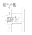
図1は本実施形態の高電圧コネクタのリーク防止構造が適用されたモータを搭載するハイブリッド型トラックを示す全体構成図である。以下、車両を主体として前後、左右及び上下方向を規定して説明する。
[First Embodiment]
Hereinafter, a first embodiment in which the present invention is embodied in a leak prevention structure for a high-voltage connector in a hybrid truck motor will be described.
FIG. 1 is an overall configuration diagram showing a hybrid truck on which a motor to which a leakage prevention structure for a high voltage connector according to this embodiment is applied is mounted. Hereinafter, description will be made by defining the front and rear, the left and right, and the up and down directions with the vehicle as a main body.
ハイブリッド型トラック1はいわゆるパラレル型ハイブリッド車両として構成されており、以下の説明では、車両と称する場合もある。車両1には走行用動力源としてディーゼルエンジン(以下、エンジンという)2、及び例えば永久磁石式同期電動機のように発電機としても作動可能なモータ3が搭載されている。
エンジン1の出力軸にはクラッチ4の入力側が連結され、クラッチ4の出力側にはモータ3のロータ3a(図3に示す)を介して自動変速機5の入力側が連結されている。自動変速機5の出力側にはプロペラシャフト6を介して差動装置7が連結され、差動装置7には駆動軸8を介して左右の駆動輪9が連結されている。モータ3にはインバータ10を介してバッテリ11が接続され、バッテリ11の電力供給を受けてモータ3が作動するようになっている。
The
The input side of the clutch 4 is connected to the output shaft of the
エンジン2及びモータ3の運転、クラッチ4の断接操作、自動変速機5の変速操作などはコントローラ13により制御される。例えばコントローラ13は、運転者によるアクセル操作などに基づき車両1を走行させるために必要な要求トルクを算出し、その要求トルクやバッテリ11のSOCなどに基づき車両1の走行モードを選択する。
例えばコントローラ13は、走行モードとしてエンジン単独のE/Gモードを選択すると、モータ3を停止させたままクラッチ4を接続した上でエンジン2を運転し、エンジン2の駆動力を駆動輪9側に伝達して車両1を走行させる。またコントローラ13は、走行モードとしてモータ単独のEVモードを選択すると、エンジン2を停止させたままクラッチ4を切断した上でインバータ10を駆動制御してモータ3を運転し、モータ3の駆動力を駆動輪9側に伝達して車両1を走行させる。
The operation of the
For example, when the
またコントローラ13は、走行モードとしてエンジン2及びモータ3を併用するHEVモードを選択すると、クラッチ4を接続した上でエンジン2及びモータ3を運転し、それらの駆動力を駆動輪9側に伝達して車両1を走行させる。各走行モードにおいてコントローラ13は、要求トルクを達成するようにエンジン2及びモータ3の運転を制御し、例えばHEVモードでは要求トルクをエンジン2側とモータ3側とに配分し、それぞれの要求トルクを達成するようにエンジン2及びモータ3の運転を制御する。
Further, when the HEV mode in which the
EVモードやHEVモードでのモータ3の運転は、コントローラ13からの指令を受けたインバータ10により制御される。例えば車両1の加速時には、バッテリ11に蓄えられた直流電力がインバータ10により交流電力に変換されてモータ3に供給され(力行制御)、モータ3が発生した正の駆動力が駆動輪9側に伝達される。また車両1の減速時には、駆動輪9側からの逆駆動によりモータ3が発電機として作動し(回生制御)、モータ3の負の駆動力が制動力として駆動輪9側に伝達されると共に、発電された交流電力がインバータ10で直流電力に変換されてバッテリ11に充電される。
The operation of the
このようなモータ3とインバータ10間の電力の入出力は高電圧ケーブルを介して行われており、以下、モータ3の構造、特にモータ3に対する高電圧ケーブルの接続箇所の構造を説明する。
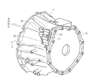
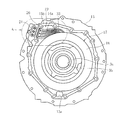
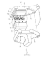
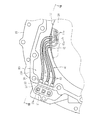
図2はモータ3を斜め後方から見た斜視図、図3はリアカバーを外してモータ3を後方から見た背面図である。
Such power input / output between the
FIG. 2 is a perspective view of the
モータ3及びクラッチ4を収容するハウジング15は前方及び後方に開口する円筒状をなし、その前側は図示しないフロントカバーで閉鎖され、後側はリアカバー16で閉鎖されている。クラッチ4はハウジング15内の前側位置に配設され、その後側の中心部に多数のロータコアを備えたロータ3aが回転可能に支持されている。
ハウジング15内において、ロータ3aの周囲には環状をなすステータ17が配設されている。ステータ17の環状をなすコイルカバー18内にはU,V,Wの3相のコイルが交互に列設されており、これらのロータ3a及びステータ17によりモータ3が構成されている。
コイルカバー18内でコイルには各相毎にそれぞれ高電圧ケーブル(計3本であり、以下、内部ケーブル14aという)が接続され、これらの内部ケーブル14aを介したインバータ10側からの電力供給により、各相のコイルが順次通電されて磁界を発生する。この磁界によりロータ3aには力行或いは回生方向のトルクが付与されて、上記のように駆動力としてモータ3から出力される。
A
In the
In the
ロータ3aの中心にはスプライン孔3bが前後方向に貫設され、スプライン孔3b内には自動変速機5の入力軸が後方から嵌入している。入力軸の先端はスプライン孔3bを貫通してクラッチ4の出力側に嵌入し、これによりクラッチ4の出力側と共にロータ3a及び自動変速機5の入力軸が常に一体回転し、モータ3の駆動力が単独で、或いはエンジン1の駆動力と共に自動変速機5に入力される。
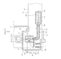
図4は高電圧コネクタの箇所を示す図3のA部分の拡大断面図、図5は同じく高電圧コネクタの箇所を示す図4のV−V線断面図、図6は同じく高電圧コネクタの箇所を示す図2のB矢視図である。
A
4 is an enlarged sectional view of a portion A in FIG. 3 showing the location of the high voltage connector, FIG. 5 is a sectional view taken along the line V-V in FIG. 4 showing the location of the high voltage connector, and FIG. It is a B arrow line view of FIG.
モータ3の運転中においてステータ17のコイルは通電により発熱するため、その冷却対策としてコイルカバー18内には常に冷却用オイルが供給されるようになっている。図4,5に示すように、コイルカバー18の外周面の最上部には上部排出孔18aが開口形成され、コイルカバー18内でコイルの冷却により温度上昇したオイルは上部排出孔18aから外部(ハウジング15内)に溢流する。溢流したオイルはコイルカバー18の外周面を伝って流れ落ち、ハウジング15内の下部に開口形成された下部排出孔15a(図3に示す)から図示しないオイルパンに回収されるようになっている。本実施形態では、自動変速機5内を循環するATF(Automatic Transmission Fluid)をオイルとして流用しているが、これに限るものではなく、コイル冷却用の専用のオイル循環システムを設けてもよい。
During operation of the
図4,5に示すように、ハウジング15の左側上部は外部に向けて膨出する形状をなし、この膨出部15bの形成によりハウジング15の内壁とコイルカバー18の外周面との間には収容空間19が形成されている。収容空間19内には高電圧コネクタ20が配設され、以下に述べるように、この高電圧コネクタ20を介して上記した各相の内部ケーブル14aがインバータ10側からの対応する高電圧ケーブル(以下、外部ケーブル14bという)に接続されるようになっている。
As shown in FIGS. 4 and 5, the upper left portion of the
膨出部15bの後面にはコネクタ脱着部21が形成され、図5に示すように、このコネクタ脱着部21の内面側(収容部19内)に高電圧コネクタ20の絶縁ベース22が固定されている。絶縁ベース22は合成樹脂で製作されて長方形状をなし、上下方向に離間配置された各相の端子金具23の一端が絶縁ベース22で一体化されることにより高電圧コネクタ20が構成されている。
各端子金具23はそれぞれ絶縁ベース22から左側方に突出して直角に折曲され、その他端は前方に指向している。上記したコイル側からの各相の内部ケーブル14aは、上部排出孔18aを経てコイルカバー18の外部に引き出されている。各内部ケーブル14aの端部はハウジング15内を収容空間19側に向けて導かれ、それぞれ高電圧コネクタ20の端子金具23に対してボルト24及びナット25により固定されている(以下、この箇所をケーブル接続箇所26という)。
A connector attaching / detaching
Each terminal fitting 23 protrudes leftward from the insulating
また、各相の端子金具23の一端にはコネクタピン23a(一側)が突設され、これらのコネクタピン23aはコネクタ脱着部21内に突出している。図5中に仮想線で示すように、コネクタ脱着部21の箇所にはインバータ10側からの各相の外部ケーブル14bが導かれており、これらの外部ケーブル14bの端部が対応するコネクタピン23aに対して任意に接続及び切離し可能となっている。
車両1の組立工程では、車体1へのモータ3の搭載後に各コネクタピン23aに対応する外部ケーブル14bが接続される。インバータ10側とモータ3のステータ17とが各相毎に電気的に接続されることにより、上記のようにインバータ10からの電力供給でステータ17の各相のコイルが順次通電されてモータ3が作動する。
In addition, connector pins 23 a (one side) project from one end of each phase terminal fitting 23, and these connector pins 23 a protrude into the connector attaching / detaching
In the assembly process of the
収容空間19内において各相の端子金具23には、合成樹脂製の絶縁カバー27が嵌め込まれている。絶縁カバー27は後方に向けて開口する形状をなして左右に2分割されて製作されており、ケーブル接続箇所26を内包するように左右両側から互いに結合されている。絶縁カバー27内は各端子金具23毎に区画されており、これにより内部ケーブル14aが正規姿勢で保持されている。
一方、ハウジング15の膨出部15bの前面には開口部28が形成され、この開口部28を介して収容空間19内の高電圧コネクタ20が前方に露出している。開口部28にはアルミダイキャスト製のコネクタカバー29(金属部材)が図示しないボルトにより脱着可能に装着されている。
In the
On the other hand, an
コネクタカバー29にはブリーザ30が備えられ、このブリーザ30によりハウジング15の内圧の上昇が抑制されるようになっている。コネクタカバー29は高電圧コネクタ20のケーブル接続箇所26の近接に位置しているが、上記した絶縁カバー27でコネクタカバー29との間の沿面距離が確保されることにより、双方の部材26,29間でのリークの発生が防止されている。
ハウジング15の開口部28は、各相の端子金具23に対して内部ケーブル14aの端部をボルト24及びナット25で接続する作業を実施するために形成されたものである。作業完了後の開口部28はコネクタカバー29により閉鎖されて、ハウジング15内への異物などの侵入が防止される。
The
The
以上のように、ケーブル接続箇所26とコネクタカバー29との間のリークが絶縁カバー27により防止されている。しかしながら、[発明が解決しようとする課題]でも述べたように、ハウジング15内の結露により絶縁カバー27の分割面27aの間隙に水分が侵入すると、分割面27aの間隙を介して近接位置にあるケーブル接続箇所26とコネクタカバー29との間でリークが発生してしまう。
As described above, the insulating
このような問題点を鑑みて本発明者は、ケーブル接続箇所26及び絶縁カバー27をオイルで濡らした状態では、コネクタカバー29との間でリークが発生し難くなる現象に着目した。即ち、一般的にオイル(ATFも含む)は導電性を有さないため、ケーブル接続箇所26がオイルで濡れると、その表面に形成された油膜によりリークを抑制する作用が奏される。また、絶縁カバー27がオイルで濡れると分割面27aの間隙にオイルが侵入するため、たとえ結露が生じても分割面27aの間隙に水分が侵入せず、本来の沿面距離を確保できる。
そして、この対策のために必要なオイルは、ケーブル接続箇所26の近接に位置するコイルカバー18の上部排出孔18aから常に溢流している。そこで、本実施形態では、この溢流するオイルをケーブル接続箇所26に案内することによりコネクタカバー29との間のリークを防止しており、以下、当該対策について説明する。
In view of such a problem, the present inventor has focused on a phenomenon in which leakage hardly occurs between the
And the oil required for this countermeasure always overflows from the
ハウジング15の収容空間19内には、オイルを案内するためのオイルガイド33が配設されている。全体としてオイルガイド33は筒状をなし、その一端は下方に向けて開口して上部排出孔18aに接続されている。上部排出孔18aの箇所からオイルガイド33は上方且つ左方に向けて緩やかな円弧状をなすように延設され、その他端は前方に湾曲してケーブル接続箇所26に向けて開口している。オイルガイド33は合成樹脂により前後に2分割して成型された上で(図5中に分割面33aを示す)相互に結合されて所期の筒状をなし、図示しないブラケットによりハウジング15内の所定の位置に固定されている。
An
上部排出孔18aに接続されたオイルガイド33の一端には予備排出孔33bが形成され、この予備排出孔33bはコイルカバー18の外周面に沿うように左側方に向けて開口している。本実施形態では、オイルガイド33の他端(ケーブル接続箇所26側)の開口面積と予備排出孔33bの開口面積とが略等しく設定されている。
但し、双方の開口面積の設定はこれに限るものではなく、任意に変更可能である。また、予備排出孔33bの位置は上記に限定されるものではなく任意に変更可能であり、オイルガイド33の別の位置に設けてもよい。さらに予備排出孔33bを省略し、代わりに上部排出孔18aの一部をオイルガイド33と接続することなく開口させてもよい。
A
However, the setting of both opening areas is not limited to this, and can be arbitrarily changed. Further, the position of the
オイルガイド33はオイルの案内と共に、上記した内部ケーブル14aの保持及び保護の役割も果たす。そのために、上部排出孔18aから引き出された各相の内部ケーブル14aはオイルガイド33内に挿通され、このオイルガイド33内を経てケーブル接続箇所26まで延設されている。
オイルガイド33内にはその延設方向に沿って2条の隔壁33cが形成され、これらの隔壁33cにより区画された3本の通路33d内に各相の内部ケーブル14aがそれぞれ挿通されて相互の接触が防止されている。各通路33dは十分な断面積を有しており、内部ケーブル14aを挿通した状態でも周囲にオイルを案内するための間隙が確保されている。
但し、オイルガイド33の形状や材質は上記に限ることはなく任意に変更可能であり、隔壁33cについても必ずしも形成する必要はなく、これを省略してもよい。
The
In the
However, the shape and material of the
次に、以上のように構成された高電圧コネクタ20のリーク防止構造の作用を説明する。
モータ3の運転中において、コイルを冷却後のオイルは、コイルカバー18の上部排出孔18aから溢流することなくオイルガイド33内に流入する。オイルガイド33内でオイルは各通路33d内を左側方に向けて案内され、さらにオイルガイド33の湾曲に倣って流通方向を前方に変更されて他端の開口部から放出される。放出されたオイルは、後方に向けて開口する絶縁カバー27内に一時的溜まった後に流れ落ち、その間に絶縁カバー27及び内部のケーブル接続箇所26、さらには周囲の端子金具23が隈無くオイルと接触して濡れた状態となる。
Next, the operation of the leak prevention structure of the
During the operation of the
従って、ケーブル接続箇所26の表面に油膜が形成されてリークが発生し難い状態に保たれる。また、絶縁カバー27の分割面27aの間隙にオイルが侵入するため、たとえ結露が生じても分割面27aの間隙に水分が侵入しなくなる。このため、分割面27aの間隙を介したリークが抑制され、本来の絶縁カバー27による沿面距離を確保できる。結果として、ケーブル接続箇所26とコネクタカバー29との間でのリークを確実に防止することができる。
また、以上の機能を奏するオイルガイド33は、射出成型などで簡単に製造できる。よって、例えば絶縁カバー27の分割面27aを手作業で接着する対策などに比較して手間がかからないため、製造コストを高騰させることなく上記リーク防止の効果を達成することができる。
Accordingly, an oil film is formed on the surface of the
Further, the
一方、上部排出孔18aを介してオイルガイド33内に流入したオイルの約半分は、予備排出孔33bから直接的に外部に排出される。このオイルの排出は、ブリーザ30から外部へのオイル漏れの防止を目的とした対策である。
即ち、全てのオイルをケーブル接続箇所26側に放出すると、特にオイル粘度が低い冷態時などに収容空間19内にオイルが充満してブリーザ30から外部に溢れてしまう。予備排出孔33bからのオイルの排出によりケーブル接続箇所26側に放出されるオイル量を適正量まで減少させることで、このような事態を未然に防止することができる。
On the other hand, about half of the oil that has flowed into the
That is, if all the oil is discharged to the
[第2実施形態]
次に、本発明を別のハイブリッド型トラック用モータ3における高電圧コネクタのリーク防止構造に具体化した第2実施形態を説明する。第1実施形態に対する本実施形態の相違点はオイルガイドの構成にあり、その他の箇所は同一構成である。そこで、共通する構成の箇所は同一部材番号を付して説明を省略し、相違点を重点的に述べる。
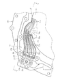
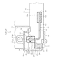
図7は高電圧コネクタ20の箇所を示す図4に対応する拡大断面図、図8は同じく高電圧コネクタ20の箇所を示す図7のVIII−VIII線断面図である。
[Second Embodiment]
Next, a second embodiment in which the present invention is embodied in a leakage prevention structure for a high-voltage connector in another
7 is an enlarged cross-sectional view corresponding to FIG. 4 showing the location of the high-
本実施形態のオイルガイド41は、コイルカバー18の上部排出孔18aに固定される接続プレート42と各相の内部ケーブル14aに対応する3本のチューブ43とから構成されている。接続プレート42は上部排出孔18aを閉鎖するように取り付けられ、各相の内部ケーブル14aと対応するように3つの貫通孔42aが貫設されている。これらの貫通孔42aを介して内部ケーブル14aがコイルカバー18内から外部に引き出され、その端部は高電圧コネクタ20の端子金具23にボルト24及びナット25で固定されてケーブル接続箇所26を構成している。
各相の内部ケーブル14aはチューブ43によりそれぞれ被覆されている。チューブ43の内径は内部ケーブル14aの外径よりも大きく設定されており、内部ケーブル14aの周囲にオイルを案内するための十分な間隙が確保されている。接続プレート42の上面には各貫通孔42aを中心として接続口42bが形成され、これらの接続口42bに各チューブ43の一端がそれぞれ嵌め込まれている。また、各チューブ43は内部ケーブル14aに倣ってケーブル接続箇所26まで延設され、このケーブル接続箇所26に向けて開口している。
The
Each phase
従って、この第2実施形態においても、コイルを冷却後のオイルがオイルガイド41の各チューブ43内を案内されてケーブル接続箇所26に向けて放出される。このため重複する説明はしないが、絶縁カバー27及びケーブル接続箇所26を常にオイルで濡れた状態に保ってリークを防止できる。
加えて、本実施形態のオイルガイド41を構成するチューブ43は既製品、例えばケーブル保護のために市販されているチューブなどを流用できるため、第1実施形態よりもさらに製造コストを低減することができる。
なお、接続プレート42に第1実施形態の予備排出孔33bと同様の排出孔を形成してもよく、このように構成すれば、第1実施形態で述べた予備排出孔33bに関する作用効果も得られる。
Therefore, also in the second embodiment, the oil after cooling the coil is guided through the
In addition, since the
Note that the
以上で実施形態の説明を終えるが、本発明の態様はこの実施形態に限定されるものではない。例えば上記実施形態では、ハイブリッド型トラック用モータ3における高電圧コネクタ20のリーク防止構造として具体化したが、適用する車両1はこれに限るものではない。例えばバスや乗用車に適用してもよいし、走行用動力源としてモータ3のみを搭載した電気自動車として具体化してもよい。
また、上記実施形態では、内部ケーブル14aの接続作業のためにハウジング15に開口部28を形成し、その開口部28を閉鎖するコネクタカバー29とケーブル接続箇所26との間のリークを防止したが、これに限るものではない。例えばコネクタカバー29を設けない場合であっても、ハウジング15の内壁とケーブル接続箇所26との間でリークが発生する。よって、このようなリークの防止を目的として上記実施形態と同様の構成を実施してもよい。
This is the end of the description of the embodiment, but the aspect of the present invention is not limited to this embodiment. For example, in the above-described embodiment, the leakage prevention structure of the high-
Moreover, in the said embodiment, although the
3 モータ
3a ロータ
14a 内部ケーブル
14b 外部ケーブル
15 ハウジング
17 ステータ
18 コイルカバー
18a 上部排出孔
20 高電圧コネクタ
23 端子金具
23a コネクタピン(一側)
26 ケーブル接続箇所
27 絶縁カバー
28 開口部
29 コネクタカバー(金属部材)
30 ブリーザ
33,41 オイルガイド
33b 予備排出孔
43 チューブ
3
26
30
Claims (4)
上記コイルカバーの一側に開口形成されて、上記各相のコイルの冷却のために上記コイルカバー内に流入されたオイルを外部に排出する排出孔と、
上記コイルカバー内で各相毎に上記コイルに一端を接続されると共に、他端が上記排出孔を介してそれぞれ外部に引き出された各相の内部ケーブルと、
上記ハウジング内の一側に配設されて、各相毎に設けられた端子金具に上記内部ケーブルの他端がそれぞれ接続される一方、各相の端子金具の一側を上記ハウジングの外面に露出させて電源側の外部ケーブルを接続可能とした高電圧コネクタと、
2分割により構成されて、上記端子金具に対する上記内部ケーブルの接続箇所を内包するように互いに結合し、該内部ケーブルの接続箇所に近接して位置する金属部材との間のリークを防止する絶縁カバーと、
内部に上記各相の内部ケーブルが挿通されると共に、上記コイルカバーの排出孔から排出されるオイルを上記端子金具に対する内部ケーブルの接続箇所に案内するオイルガイドと
を備えたことを特徴とする車両用モータにおける高電圧コネクタのリーク防止構造。 A vehicular motor comprising a rotor rotatably supported in a housing, an annular coil cover disposed around the rotor, and coils of each phase arranged alternately in the coil cover to constitute a stator. In
An opening formed on one side of the coil cover, for discharging oil flowing into the coil cover to cool the coils of each phase;
One end is connected to the coil for each phase in the coil cover, and the other end of each phase is pulled out to the outside through the discharge hole, and an internal cable for each phase,
The other end of the internal cable is connected to a terminal fitting provided for each phase on one side of the housing, while one side of the terminal fitting for each phase is exposed to the outer surface of the housing. A high-voltage connector that allows the external cable on the power supply side to be connected,
Insulating cover that is configured by two parts and is coupled to each other so as to include the connection portion of the internal cable with respect to the terminal fitting, and prevents leakage between the metal member located in the vicinity of the connection portion of the internal cable When,
And an oil guide for guiding the oil discharged from the discharge hole of the coil cover to the connection portion of the internal cable with respect to the terminal fitting. Leakage prevention structure for high-voltage connectors in motors.
上記金属部材は、上記ハウジングの開口部を閉鎖するコネクタカバーであることを特徴とする請求項1記載の車両用モータにおける高電圧コネクタのリーク防止構造。 On the outer surface of the housing, an opening for connecting the internal cable to the terminal fitting of each phase is formed,
2. The structure for preventing leakage of a high-voltage connector in a vehicle motor according to claim 1, wherein the metal member is a connector cover that closes an opening of the housing.
上記オイルガイドは、上記排出孔からのオイルの一部を上記内部ケーブルの接続箇所に案内することなく、直接的に外部に排出する予備排出孔を備えたことを特徴とする請求項1または2記載の車両用モータにおける高電圧コネクタのリーク防止構造。 The housing is provided with a breather for adjusting internal pressure at a position close to a connection location of the internal cable to the terminal fitting,
3. The oil guide according to claim 1, further comprising a preliminary discharge hole for discharging a part of the oil from the discharge hole directly to the outside without guiding the oil to a connection portion of the internal cable. A structure for preventing leakage of a high-voltage connector in the vehicle motor described above.
Priority Applications (1)
| Application Number | Priority Date | Filing Date | Title |
|---|---|---|---|
| JP2012225989A JP2014079110A (en) | 2012-10-11 | 2012-10-11 | Leak preventing structure of high-voltage connector in vehicle motor |
Applications Claiming Priority (1)
| Application Number | Priority Date | Filing Date | Title |
|---|---|---|---|
| JP2012225989A JP2014079110A (en) | 2012-10-11 | 2012-10-11 | Leak preventing structure of high-voltage connector in vehicle motor |
Publications (1)
| Publication Number | Publication Date |
|---|---|
| JP2014079110A true JP2014079110A (en) | 2014-05-01 |
Family
ID=50783975
Family Applications (1)
| Application Number | Title | Priority Date | Filing Date |
|---|---|---|---|
| JP2012225989A Pending JP2014079110A (en) | 2012-10-11 | 2012-10-11 | Leak preventing structure of high-voltage connector in vehicle motor |
Country Status (1)
| Country | Link |
|---|---|
| JP (1) | JP2014079110A (en) |
Cited By (1)
| Publication number | Priority date | Publication date | Assignee | Title |
|---|---|---|---|---|
| WO2023277059A1 (en) | 2021-06-30 | 2023-01-05 | 株式会社アイシン | Drive device for vehicles |
-
2012
- 2012-10-11 JP JP2012225989A patent/JP2014079110A/en active Pending
Cited By (2)
| Publication number | Priority date | Publication date | Assignee | Title |
|---|---|---|---|---|
| WO2023277059A1 (en) | 2021-06-30 | 2023-01-05 | 株式会社アイシン | Drive device for vehicles |
| US12163581B2 (en) | 2021-06-30 | 2024-12-10 | Aisin Corporation | Vehicle drive device |
Similar Documents
| Publication | Publication Date | Title |
|---|---|---|
| US7851954B2 (en) | Vehicle drive device | |
| US10097066B2 (en) | Electric machine for vehicle | |
| JP4692263B2 (en) | Vehicle drive device | |
| US8397845B2 (en) | Drive apparatus for vehicle | |
| JP5769386B2 (en) | Electric propulsion device and electric vehicle equipped with the same | |
| US10014794B2 (en) | Power inverter assembly for a vehicle | |
| US10618418B2 (en) | Vehicle charging systems incorporating phase change materials for absorbing heat during charging events | |
| CN107426943B (en) | Vehicle power module assembly and manifold | |
| KR20100049113A (en) | Vehicle | |
| EP2889175B1 (en) | Integrated high-current unit installed in electric vehicle | |
| US20220263389A1 (en) | Driving unit and vehicle | |
| US20090206688A1 (en) | Cooling structure for stator | |
| CN110649826A (en) | Vehicle power module assembly | |
| US11670443B2 (en) | Liquid cooled inductor via nozzle spray | |
| US11854729B2 (en) | Direct liquid cooled inductor | |
| CN114825694A (en) | Rotor punching sheet, rotor, driving motor and electric vehicle | |
| JP2008218732A (en) | Reactor fixing structure | |
| US20220415556A1 (en) | Liquid cooled inductor | |
| JP2014079110A (en) | Leak preventing structure of high-voltage connector in vehicle motor | |
| JP2007118809A (en) | Hybrid vehicle | |
| US12614989B2 (en) | Power converter | |
| JP3876798B2 (en) | Power converter for vehicle | |
| JP2015105088A (en) | Cooling device of vehicular controller | |
| CN118683324A (en) | Electric Vehicles | |
| JP2009153264A (en) | Power control unit cooling structure |