JP7596397B2 - High Power Shielded Busbars for Electric Vehicle Charging and Power Distribution - Google Patents
High Power Shielded Busbars for Electric Vehicle Charging and Power Distribution Download PDFInfo
- Publication number
- JP7596397B2 JP7596397B2 JP2022555793A JP2022555793A JP7596397B2 JP 7596397 B2 JP7596397 B2 JP 7596397B2 JP 2022555793 A JP2022555793 A JP 2022555793A JP 2022555793 A JP2022555793 A JP 2022555793A JP 7596397 B2 JP7596397 B2 JP 7596397B2
- Authority
- JP
- Japan
- Prior art keywords
- electric vehicle
- power distribution
- distribution system
- vehicle power
- busbar
- Prior art date
- Legal status (The legal status is an assumption and is not a legal conclusion. Google has not performed a legal analysis and makes no representation as to the accuracy of the status listed.)
- Active
Links
Images


Classifications
-
- B—PERFORMING OPERATIONS; TRANSPORTING
- B60—VEHICLES IN GENERAL
- B60L—PROPULSION OF ELECTRICALLY-PROPELLED VEHICLES; SUPPLYING ELECTRIC POWER FOR AUXILIARY EQUIPMENT OF ELECTRICALLY-PROPELLED VEHICLES; ELECTRODYNAMIC BRAKE SYSTEMS FOR VEHICLES IN GENERAL; MAGNETIC SUSPENSION OR LEVITATION FOR VEHICLES; MONITORING OPERATING VARIABLES OF ELECTRICALLY-PROPELLED VEHICLES; ELECTRIC SAFETY DEVICES FOR ELECTRICALLY-PROPELLED VEHICLES
- B60L53/00—Methods of charging batteries, specially adapted for electric vehicles; Charging stations or on-board charging equipment therefor; Exchange of energy storage elements in electric vehicles
- B60L53/10—Methods of charging batteries, specially adapted for electric vehicles; Charging stations or on-board charging equipment therefor; Exchange of energy storage elements in electric vehicles characterised by the energy transfer between the charging station and the vehicle
- B60L53/14—Conductive energy transfer
-
- B—PERFORMING OPERATIONS; TRANSPORTING
- B60—VEHICLES IN GENERAL
- B60R—VEHICLES, VEHICLE FITTINGS, OR VEHICLE PARTS, NOT OTHERWISE PROVIDED FOR
- B60R16/00—Electric or fluid circuits specially adapted for vehicles and not otherwise provided for; Arrangement of elements of electric or fluid circuits specially adapted for vehicles and not otherwise provided for
- B60R16/02—Electric or fluid circuits specially adapted for vehicles and not otherwise provided for; Arrangement of elements of electric or fluid circuits specially adapted for vehicles and not otherwise provided for electric constitutive elements
- B60R16/0207—Wire harnesses
- B60R16/0215—Protecting, fastening and routing means therefor
-
- H—ELECTRICITY
- H01—ELECTRIC ELEMENTS
- H01B—CABLES; CONDUCTORS; INSULATORS; SELECTION OF MATERIALS FOR THEIR CONDUCTIVE, INSULATING OR DIELECTRIC PROPERTIES
- H01B7/00—Insulated conductors or cables characterised by their form
- H01B7/009—Cables with built-in connecting points or with predetermined areas for making deviations
-
- H—ELECTRICITY
- H01—ELECTRIC ELEMENTS
- H01B—CABLES; CONDUCTORS; INSULATORS; SELECTION OF MATERIALS FOR THEIR CONDUCTIVE, INSULATING OR DIELECTRIC PROPERTIES
- H01B9/00—Power cables
- H01B9/02—Power cables with screens or conductive layers, e.g. for avoiding large potential gradients
-
- H—ELECTRICITY
- H01—ELECTRIC ELEMENTS
- H01R—ELECTRICALLY-CONDUCTIVE CONNECTIONS; STRUCTURAL ASSOCIATIONS OF A PLURALITY OF MUTUALLY-INSULATED ELECTRICAL CONNECTING ELEMENTS; COUPLING DEVICES; CURRENT COLLECTORS
- H01R11/00—Individual connecting elements providing two or more spaced connecting locations for conductive members which are, or may be, thereby interconnected, e.g. end pieces for wires or cables supported by the wire or cable and having means for facilitating electrical connection to some other wire, terminal, or conductive member, blocks of binding posts
- H01R11/11—End pieces or tapping pieces for wires, supported by the wire and for facilitating electrical connection to some other wire, terminal or conductive member
- H01R11/12—End pieces terminating in an eye, hook, or fork
-
- H—ELECTRICITY
- H01—ELECTRIC ELEMENTS
- H01R—ELECTRICALLY-CONDUCTIVE CONNECTIONS; STRUCTURAL ASSOCIATIONS OF A PLURALITY OF MUTUALLY-INSULATED ELECTRICAL CONNECTING ELEMENTS; COUPLING DEVICES; CURRENT COLLECTORS
- H01R25/00—Coupling parts adapted for simultaneous co-operation with two or more identical counterparts, e.g. for distributing energy to two or more circuits
- H01R25/16—Rails or bus-bars provided with a plurality of discrete connecting locations for counterparts
- H01R25/161—Details
- H01R25/162—Electrical connections between or with rails or bus-bars
-
- H—ELECTRICITY
- H02—GENERATION; CONVERSION OR DISTRIBUTION OF ELECTRIC POWER
- H02G—INSTALLATION OF ELECTRIC CABLES OR LINES, OR OF COMBINED OPTICAL AND ELECTRIC CABLES OR LINES
- H02G5/00—Installations of bus-bars
- H02G5/06—Totally-enclosed installations, e.g. in metal casings
- H02G5/061—Tubular casings
-
- B—PERFORMING OPERATIONS; TRANSPORTING
- B60—VEHICLES IN GENERAL
- B60L—PROPULSION OF ELECTRICALLY-PROPELLED VEHICLES; SUPPLYING ELECTRIC POWER FOR AUXILIARY EQUIPMENT OF ELECTRICALLY-PROPELLED VEHICLES; ELECTRODYNAMIC BRAKE SYSTEMS FOR VEHICLES IN GENERAL; MAGNETIC SUSPENSION OR LEVITATION FOR VEHICLES; MONITORING OPERATING VARIABLES OF ELECTRICALLY-PROPELLED VEHICLES; ELECTRIC SAFETY DEVICES FOR ELECTRICALLY-PROPELLED VEHICLES
- B60L2270/00—Problem solutions or means not otherwise provided for
- B60L2270/10—Emission reduction
- B60L2270/14—Emission reduction of noise
- B60L2270/147—Emission reduction of noise electro magnetic [EMI]
-
- B—PERFORMING OPERATIONS; TRANSPORTING
- B60—VEHICLES IN GENERAL
- B60Y—INDEXING SCHEME RELATING TO ASPECTS CROSS-CUTTING VEHICLE TECHNOLOGY
- B60Y2200/00—Type of vehicle
- B60Y2200/90—Vehicles comprising electric prime movers
- B60Y2200/91—Electric vehicles
-
- B—PERFORMING OPERATIONS; TRANSPORTING
- B60—VEHICLES IN GENERAL
- B60Y—INDEXING SCHEME RELATING TO ASPECTS CROSS-CUTTING VEHICLE TECHNOLOGY
- B60Y2410/00—Constructional features of vehicle sub-units
- B60Y2410/115—Electric wiring; Electric connectors
-
- Y—GENERAL TAGGING OF NEW TECHNOLOGICAL DEVELOPMENTS; GENERAL TAGGING OF CROSS-SECTIONAL TECHNOLOGIES SPANNING OVER SEVERAL SECTIONS OF THE IPC; TECHNICAL SUBJECTS COVERED BY FORMER USPC CROSS-REFERENCE ART COLLECTIONS [XRACs] AND DIGESTS
- Y02—TECHNOLOGIES OR APPLICATIONS FOR MITIGATION OR ADAPTATION AGAINST CLIMATE CHANGE
- Y02T—CLIMATE CHANGE MITIGATION TECHNOLOGIES RELATED TO TRANSPORTATION
- Y02T10/00—Road transport of goods or passengers
- Y02T10/60—Other road transportation technologies with climate change mitigation effect
- Y02T10/70—Energy storage systems for electromobility, e.g. batteries
-
- Y—GENERAL TAGGING OF NEW TECHNOLOGICAL DEVELOPMENTS; GENERAL TAGGING OF CROSS-SECTIONAL TECHNOLOGIES SPANNING OVER SEVERAL SECTIONS OF THE IPC; TECHNICAL SUBJECTS COVERED BY FORMER USPC CROSS-REFERENCE ART COLLECTIONS [XRACs] AND DIGESTS
- Y02—TECHNOLOGIES OR APPLICATIONS FOR MITIGATION OR ADAPTATION AGAINST CLIMATE CHANGE
- Y02T—CLIMATE CHANGE MITIGATION TECHNOLOGIES RELATED TO TRANSPORTATION
- Y02T10/00—Road transport of goods or passengers
- Y02T10/60—Other road transportation technologies with climate change mitigation effect
- Y02T10/7072—Electromobility specific charging systems or methods for batteries, ultracapacitors, supercapacitors or double-layer capacitors
-
- Y—GENERAL TAGGING OF NEW TECHNOLOGICAL DEVELOPMENTS; GENERAL TAGGING OF CROSS-SECTIONAL TECHNOLOGIES SPANNING OVER SEVERAL SECTIONS OF THE IPC; TECHNICAL SUBJECTS COVERED BY FORMER USPC CROSS-REFERENCE ART COLLECTIONS [XRACs] AND DIGESTS
- Y02—TECHNOLOGIES OR APPLICATIONS FOR MITIGATION OR ADAPTATION AGAINST CLIMATE CHANGE
- Y02T—CLIMATE CHANGE MITIGATION TECHNOLOGIES RELATED TO TRANSPORTATION
- Y02T90/00—Enabling technologies or technologies with a potential or indirect contribution to GHG emissions mitigation
- Y02T90/10—Technologies relating to charging of electric vehicles
- Y02T90/14—Plug-in electric vehicles
Landscapes
- Engineering & Computer Science (AREA)
- Mechanical Engineering (AREA)
- Power Engineering (AREA)
- Transportation (AREA)
- Electric Propulsion And Braking For Vehicles (AREA)
- Arrangement Or Mounting Of Propulsion Units For Vehicles (AREA)
- Details Of Connecting Devices For Male And Female Coupling (AREA)
- Installation Of Indoor Wiring (AREA)
- Connection Of Batteries Or Terminals (AREA)
- Current-Collector Devices For Electrically Propelled Vehicles (AREA)
- Elimination Of Static Electricity (AREA)
- Charge And Discharge Circuits For Batteries Or The Like (AREA)
Description
本開示の主題は、全体として電気自動車の充電と配電のための高電力シールドバスバーに関するシステムと方法に関する。 The subject matter of this disclosure generally relates to systems and methods relating to high power shielded busbars for charging and distributing power to electric vehicles.
従来の自動車用車載配線は、電力信号またはデータ信号を一端から他端へと伝達するための複数のケーブルを含んでいる。従来のケーブル設計では、自動車内部の高電力配電における需要増を支えることができない。さらに、数百キロワットを超過する高電力を扱うためにケーブルの設計を改善することが常に必要とされている。従来のケーブルは、電気自動車の充電と配電のための丈夫で剛性のある高電力シールド支持部を設けていない。その上、電子モジュールの数が増えると、従来のケーブルに伴う複雑性とコストが過大になる。加えて、大型ケーブルアセンブリのワイヤまたは導体に不良があると、絶縁が困難となり、修理コストがかさむおそれがある。 Traditional automotive wiring includes multiple cables for transmitting power or data signals from one end to the other. Traditional cable designs cannot support the increasing demand for high power distribution inside the vehicle. Furthermore, there is a constant need to improve cable designs to handle high power in excess of hundreds of kilowatts. Traditional cables do not provide a strong and rigid high power shield support for charging and power distribution in electric vehicles. Moreover, the increasing number of electronic modules leads to excessive complexity and cost associated with traditional cables. In addition, defects in the wires or conductors of large cable assemblies can lead to insulation difficulties and high repair costs.
要約を目的として、特定の態様、利点、および新規特徴が本明細書中に記載される。このような利点がすべて、いずれか1つの特別な実施形態に従い達成され得るわけではないことを理解されたい。このため、本開示の主題は、本明細書中で教示または示唆され得るようなすべての利点を達成することなく1つの利点もしくは利点群を達成または最適化するように、実施または実行されてよい。 For purposes of summary, certain aspects, advantages, and novel features are described herein. It is to be understood that not all such advantages may be achieved in accordance with any one particular embodiment. Thus, the subject matter of the present disclosure may be implemented or performed to achieve or optimize an advantage or group of advantages without achieving all advantages as may be taught or suggested herein.
本明細書に記載の主題のうち1または複数の変形についての詳細は、下記の添付図面と詳細な説明において明らかにする。本明細書に記載される主題の他の特徴と利点は、この詳細な説明と図面、および特許請求の範囲から明白となる。しかし、本開示の主題は、開示されるいずれの特別な実施形態にも限定されない。 Details of one or more variations of the subject matter described herein are set forth in the accompanying drawings and detailed description below. Other features and advantages of the subject matter described herein will be apparent from the detailed description and drawings, and from the claims. However, the subject matter of this disclosure is not limited to any particular embodiment disclosed.
本明細書に組み込まれるとともにその一部を構成する添付図面は、本明細書に開示される主題の特定の態様を示しており、下記に提供する本開示の実装形態に関連する原理の一部を発明の詳細な説明とともに説明する助けとなる。 The accompanying drawings, which are incorporated in and constitute a part of this specification, illustrate certain aspects of the subject matter disclosed herein and, together with the detailed description of the invention provided below, help explain some of the principles related to implementations of the present disclosure.
図1~図9は、電気自動車内で充電と配電を行うために使用される高電力シールドバスバー(high power shielded busbar)の様々な実施形態を図示する。 Figures 1-9 illustrate various embodiments of high power shielded busbars used for charging and distributing power in electric vehicles.
これらの図は、絶対的または比較上の観点で正確な縮尺でなくてよく、例示的であると意図される。特徴と要素の相対的配置は、例示を明瞭にする目的で修正されている場合がある。差し支えなければ、同じまたは同様の参照番号は、1または複数の実施形態に従い、同じ、同様の、もしくは均等な構造、特徴、態様、または要素を表している。 The figures are intended to be illustrative and may not be to scale in absolute or comparative terms. The relative placement of features and elements may be modified for purposes of clarity of illustration. Wherever possible, the same or similar reference numbers represent the same, similar, or equivalent structures, features, aspects, or elements according to one or more embodiments.
以下、様々な実施形態の完全な記載を提供するために、多数の具体的詳細を明らかにする。特定の実施形態は、これらの具体的詳細なしに、または詳細に一部の変形を伴って行われる場合がある。一部の例では、特定の特徴は、他の態様を不明瞭にしないように、あまり詳細に記載されない。これら要素または特徴のそれぞれに関連する詳細度は、1つの特徴の新規性または重要性を他のものより適格にすると解釈されるべきではない。 In the following, numerous specific details are set forth in order to provide a thorough description of various embodiments. Certain embodiments may be practiced without these specific details or with some variations in the details. In some instances, certain features are described in less detail so as not to obscure other aspects. The level of detail associated with each of these elements or features should not be construed as qualifying the novelty or importance of one feature over another.
実施形態は、電力を第1の接続点から第2の接続点に送るためのソリッドコア導体バスバーに関する。一部の実施形態では、このバスバーは、電気自動車中の1つの点から別の点に、例えば充電ポートからバッテリパックに電力を送る。一部の実施形態では、バスバーの導体は、アルミニウムや銅などのあらゆる導電性材料から形成されてよい。いくつかの実施形態では、バスバーの導体は、バスバーが所望の形状と形態を呈するように金属を鍛造することにより形成される。例えば、円筒状のアルミニウム棒が鍛造により形成されてもよく、このアルミニウム棒の端部分は、ソリッドコア導体の材料と同じ金属から所望の端部接続点を作り出すように鍛造され、ソリッドコア導体と接続点との間に接合部は存在しない。一例では、アルミニウム棒の端部は、端部が平坦化された導体を作り出すように鍛造される。この平坦化された端部には、ソリッド導体と接続点との間で直列電気接続を可能とするネジまたはボルトを受ける貫通孔が形成されてよい。接続点とソリッドコア導体との間には接合部も中間接続部もないことにより、上述のバスバーは、このような接合部または中間接続部を含む他のシステムよりも信頼度に優れる場合がある。ソリッドコア導体の鍛造端部は、平坦化された端部であることに限定されないことを理解されたい。これら端部は、本開示の趣旨から逸脱することなく接続点との接続を行うのを助長する様々な幾何学的形状へと鍛造される場合がある。例えば、鍛造端部は、円筒状、正方形状、矩形状、六角形状、ノッチ付き構成、折り曲げ構成、角度付き構成、またはその他のあらゆる構成で作製される場合がある。 Embodiments relate to a solid core conductor busbar for transmitting power from a first connection point to a second connection point. In some embodiments, the busbar transmits power from one point in an electric vehicle to another point, for example, from a charging port to a battery pack. In some embodiments, the conductor of the busbar may be formed from any conductive material, such as aluminum or copper. In some embodiments, the conductor of the busbar is formed by forging metal so that the busbar assumes a desired shape and form. For example, a cylindrical aluminum rod may be formed by forging, and end portions of the aluminum rod are forged to create the desired end connection points from the same metal as the material of the solid core conductor, and there is no joint between the solid core conductor and the connection points. In one example, the ends of the aluminum rod are forged to create a conductor with flattened ends. The flattened ends may be formed with through holes that receive screws or bolts that allow for a series electrical connection between the solid conductor and the connection points. By having no joints or intermediate connections between the connection points and the solid core conductor, the busbar described above may be more reliable than other systems that include such joints or intermediate connections. It should be understood that the forged ends of the solid core conductors are not limited to being flattened ends. The ends may be forged into various geometric shapes that facilitate making a connection with a connection point without departing from the spirit of this disclosure. For example, the forged ends may be made in a cylindrical, square, rectangular, hexagonal, notched, bent, angled, or any other configuration.
一部の実施形態では、バスバーは中央ソリッド導電性コアを、この中央導電性コアを包囲して導体の電気絶縁を提供することで導体を外部接触から電気絶縁する電気絶縁層とともに含んでいる。一実施形態では、この絶縁層は、周知の手段によって絶縁層を導電性コアの上に押出し加工、熱収縮、浸漬、吹付け、層状化、刷毛塗り、またはその他の方法で塗布することにより、ソリッドコア上に配されてよい。 In some embodiments, the busbar includes a central solid conductive core with an electrical insulation layer surrounding the central conductive core to provide electrical insulation for the conductor, thereby electrically insulating the conductor from external contact. In one embodiment, the insulation layer may be disposed on the solid core by extruding, heat shrinking, dipping, spraying, layering, brushing, or otherwise applying the insulation layer onto the conductive core by known means.
次いで、一部の実施形態では、絶縁導電性コア上に外部シールドまたはシールド層が適合されることにより、電気自動車またはその他のシステム内の目標位置への設置後に、バスバーに対してさらなる安全性、強度、および他の隣接構成部品からの電磁気絶縁が提供される。外部シールドまたはシールド層は、アルミニウムなどのあらゆる導電性材料から形成されてよい。一部の実施形態では、外部シールドまたはシールド層は導電層として機能するとともに、高電位差間で絶縁損失検出システムを補完するために例えば自動車本体に接地される場合がある。 In some embodiments, an external shield or shielding layer is then fitted over the insulated conductive core to provide the busbar with additional safety, strength, and electromagnetic isolation from other adjacent components after installation at the target location in the electric vehicle or other system. The external shield or shielding layer may be formed from any conductive material, such as aluminum. In some embodiments, the external shield or shielding layer functions as a conductive layer and may be grounded, for example to the vehicle body, to complement the insulation loss detection system across high potential differences.
一実施形態では、絶縁中央導体は、絶縁コア上での摺動を可能にする直径を有するシールドチューブ内に配されてよい。次いで、シールドバスバーは、シールドチューブがバスバーの外部絶縁層に直接かつぴったりと適合するようにシールドチューブの直径を縮小するべく圧縮加工型の中に配されてよい。これにより、中央ソリッドコア導体と、絶縁層と、絶縁層上に圧着される外部シールドとを具備する一体型の三層ソリッドコアバスバーが形成される。この種の一体型ソリッドバスバー構成を作り出すことにより、一体型バスバーは、目標用途の外形に一致する所望の構成へと曲げられる場合がある。例えば、一体型バスバーは、電気自動車内のホイールウェルまたは内部サイドパネルの外形に一致するように曲げられる場合がある。その結果得られる層状アセンブリは、ソリッドバスバーが自動車の外形に一致して複雑なパッケージング形状を形成し得るように、3D形状の曲げ加工に耐える場合がある。一体型バスバーのソリッド性は、曲げ加工プロセスを通じて互いを機械的に支えるように、各層がその下の層の上に形成されるような曲げ加工を可能にする。このソリッド性はさらに、一体型バスバーが比較的小さな断面積を維持しつつ、比較的大量の電力をシステム内の1つの点から別の点へと送る能力を有することも可能にする。 In one embodiment, the insulated center conductor may be placed in a shield tube with a diameter that allows it to slide over the insulated core. The shield busbar may then be placed in a compression mold to reduce the diameter of the shield tube so that the shield tube fits directly and snugly over the outer insulation layer of the busbar. This forms a one-piece three-layer solid core busbar with the central solid core conductor, the insulation layer, and the outer shield that is crimped onto the insulation layer. By creating this type of one-piece solid busbar configuration, the one-piece busbar may be bent into a desired configuration that matches the contours of the target application. For example, the one-piece busbar may be bent to match the contours of a wheel well or an interior side panel in an electric vehicle. The resulting layered assembly may withstand 3D shape bending so that the solid busbar can match the contours of the vehicle to form complex packaging shapes. The solidity of the one-piece busbar allows for bending such that each layer is formed on top of the layer below it to mechanically support each other throughout the bending process. This solidity also allows the one-piece busbar to have the ability to transmit relatively large amounts of power from one point to another in the system while maintaining a relatively small cross-sectional area.
一部の実施形態では、バスバーの中央コアは、剛性バスバー内の1または複数の導体から形成され、円形断面を呈してもよい。一部の実施形態では、1または複数の導体は、矩形断面を呈してもよい。一部の実施形態では、1または複数の導体のその他の断面形状が使用される。一部の実施形態では、1より多くのバスバーは、比較的高い電力負荷を第1の接続点から第2の接続点へと送るために、別のバスバーと平行に走っている。例えば、1メガワットの電力を第1の接続点から第2の接続点に送る必要のある用途では、負荷を第1の接続点から第2の接続点に分配するために、一組で2、3、4、5、6、またはそれより多くのバスバーが使用される場合がある。これにより、例えば、バスバーの通過を必要とする自動車のサイズと幾何学的構成により、一本の大径バスバーが第1の接続点から第2の接続点まで走ることができない場合、バスバーは第1の接続点から第2の接続点まで異なる経路をとることが可能となり得る。さらには、単一の接続点が電力を多数の第2の接続点に分配することも可能となり、例えば、このときに電気自動車の単一充電ポートは、電力を自動車内の多数の異なるバッテリパックに送る。その状況では、各バスバーは、正確な量の電力を自動車内の具体的な経路に沿って目標接続点へと搬送するようなサイズと形状にされてよい。 In some embodiments, the central core of the busbar may be formed from one or more conductors within the rigid busbar and may exhibit a circular cross-section. In some embodiments, the one or more conductors may exhibit a rectangular cross-section. In some embodiments, other cross-sectional shapes of the one or more conductors are used. In some embodiments, more than one busbar runs parallel to another busbar to transmit a relatively high power load from a first connection point to a second connection point. For example, in an application requiring one megawatt of power to be transmitted from a first connection point to a second connection point, a set of two, three, four, five, six, or more busbars may be used to distribute the load from the first connection point to the second connection point. This may allow the busbar to take a different route from the first connection point to the second connection point, for example, when the size and geometry of the vehicle requiring the busbar to pass does not allow a single large diameter busbar to run from the first connection point to the second connection point. It may even be possible for a single connection point to distribute power to multiple second connection points, for example when a single charging port on an electric vehicle delivers power to multiple different battery packs within the vehicle. In that situation, each bus bar may be sized and shaped to carry a precise amount of power along a specific path within the vehicle to a target connection point.
いくつかの実施形態では、高電力バスバーの構成により、同じパッケージング体積に対して2倍を超える導体断面が可能となる。このように断面が増加すると2倍以上の熱的性能が可能となり、そうしてより高い電力容量が可能になるとともに、周囲部品に対する熱クリアランス要求の減少に起因して自動車の内部体積を増大することができる。 In some embodiments, the high power busbar configuration allows for more than double the conductor cross section for the same packaging volume. This increased cross section allows for more than double the thermal performance, thus enabling higher power capacity, while allowing for increased interior volume of the vehicle due to reduced thermal clearance requirements for surrounding components.
CNC曲げ加工を利用する製造方法を通じて、曲げ部を具備するバスバーを多数の軸と2メートルを超える長さでパッケージングするために複雑なルーティングが達成される場合がある。バスバーの剛性により、従来のケーブルアセンブリに必要なクリップやブラケットなどの従来のルーティング構成部品の排除を可能にする自立型アセンブリが得られ、コストと複雑性が削減される。このプロセスにより、製造と設置の両方において時間の節約が可能となる場合がある。付加価値のないプロセスを排除することで製造方法を単純化することにより、従来のケーブルアセンブリと比較して低いコストが達成される場合がある。加えて、サイズ/質量を小さくすると、充電速度と熱的性能が上昇する場合がある。 Through manufacturing methods utilizing CNC bending, complex routing may be achieved to package busbars with bends in multiple axes and lengths in excess of 2 meters. The rigidity of the busbars results in a freestanding assembly that allows for the elimination of traditional routing components such as clips and brackets required in traditional cable assemblies, reducing cost and complexity. This process may allow for time savings in both manufacturing and installation. Lower costs may be achieved compared to traditional cable assemblies by simplifying the manufacturing method through the elimination of non-value-added processes. Additionally, reduced size/mass may increase charging speed and thermal performance.
高電力シールドバスバーは、電気自動車の周囲で広範囲に使用されてよく、高電圧バッテリパックの外部にある静的ネットワークに適し得る。高電力シールドバスバーの用途は、高電圧で高電流の用途に適しているが、この2つの組合せに限定されるものではない。 High power shielded busbars may be used extensively around electric vehicles and may be suitable for static networks external to the high voltage battery pack. Applications for high power shielded busbars are suitable for high voltage and high current applications, but are not limited to a combination of the two.
上記の高電力シールドバスバーは、優れた熱的性能(例えば、均等なサイズのケーブルの2倍の性能)、自動車および/または高電力線アセンブリの質量減少、コスト削減(例えば、部品数を少なくする、間接費(overhead)を削減する、製造コストを安くするなど)、ならびに複雑性の削減(例えば、部品数、プロセス、および/またはサプライチェーンにおける複雑性を削減する)を提供する。 The above-described high power shielded busbars provide superior thermal performance (e.g., twice the performance of equivalent sized cables), mass reduction in vehicle and/or high power line assemblies, cost reduction (e.g., fewer parts, reduced overhead, lower manufacturing costs, etc.), and reduced complexity (e.g., reduced part count, process, and/or supply chain complexity).
高電力シールドバスバーは、これまで法外なコストと質量ペナルティを被るとされていたDC高速充電電流を可能にする。高電力シールドバスバーは、400V、またはさらなる電力と電圧で350kWの充電をサポートする場合がある。高電力シールドバスバーは、このような電力値を、あらゆるシールドエンクロージャの外部にある車両の周囲に分配する場合がある。 High power shielded busbars enable DC fast charging currents that previously would have incurred prohibitive cost and mass penalties. High power shielded busbars may support 350kW charging at 400V or even higher power and voltages. High power shielded busbars may distribute these power values around the vehicle outside of any shielded enclosure.
図1は、電気自動車内部の切欠図を描くとともに、一対の高電力シールドバスバー100、102を図示する。一実施形態では、このバスバーは、剛性ソリッドコア押出加工品(アルミニウム、銅、または他の導電性材料)、絶縁層(架橋ポリエチレン(XLPE)、ポリ塩化ビニル(PVC)、シリコーン、または他の電気絶縁材料)、ならびに電磁干渉および損傷防護のためのシールドとして機能する外部導電層(銅、アルミニウム、または他の導電性材料)から形成される。図示されるように、バスバー100、102は、電気自動車充電口108とバッテリコネクタ112との間に電気接続を提供する。理解され得るように、かかる電気自動車の充電に使用されるワット数は、非常に高い可能性がある。例えば、一部の実施形態では、100kW、200kW、300kW、400kW、またはそれより高い充電ワット数を使用して、電気自動車が充電される場合がある。このため、一実施形態では、高電力シールドバスバー100、102は、このような高電力を充電から安全かつ安定して送り、充電口から電気自動車バッテリへと十分な電力を提供するようなサイズにされる。また、図1に図示するように、高電圧シールドバスバー100、102は、電気自動車の内部構成に従うように曲げられ成形される場合があることも理解されたい。例えば、バスバーは、電気自動車内のホイールウェル116の内部構成に従うように成形される場合がある。このため、バスバーは、電気自動車の床下またはサイドパネルを通過させることにより、自動車の乗員から見えなくしてもよい。
FIG. 1 depicts a cutaway view of the interior of an electric vehicle and illustrates a pair of high power shielded
図2に示すように、バスバー100、102は、第1の端部を充電口108に接続することができる。一部の実施形態では、バスバー100、102は、バスバー100、102全体の重量を支える両端部のみにて支持されるほどの十分な剛性を有する。充電口108を参照すると、レシーバ116は、バスバー100、102を充電口108に機械的かつ電気的に結合することができる。レシーバ116は、締結具118を介してバスバー100、102に締結することができる。例えば、バスバー100、102は、貫通孔(図示せず)を具備する接続部分120を有することができる。
As shown in FIG. 2, the
レシーバ116は、バスバー100、102をそれぞれ接続するための一対のレセプタクル124、128を含むプラスチック成形部分から形成することができる。レセプタクル124は、隔壁132によりレセプタクル128から隔てることができる。レシーバ116は、充電口108とバスバー100、102との間に電気的な結合(接続)を形成することができる。一部の実施形態では、レシーバ116は、接地部にさらに結合することができる。この接地部は、少なくとも一部の態様では、バスバー100、102と同様の構造を呈することができる。
The
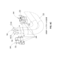
図3Aは、曲げ構成にあるバスバー100、102を示す。バスバー100、102は、曲げ加工に適し得る。バスバー100、102は、曲げのない状態で供給され、後に必要な構成へと曲げることができる。図示されるように、バスバーは、位置1、2、3、4、5、6、7、および8において具体的な角度または半径を呈するように曲げられてよい。図示されるこれらの曲げ部は、ある特別な自動車の内部構成に従うために使用されてよい構成の単なる一例である。バスバーの他の構成は本開示により企図され、各構成は自動車の具体的な構成に従うことを理解されたい。図中の100、102は、接続部分120、152を具備するバスバーを描く。接続部分152は、多くの態様で接続部分120と同様であってよい。一部の実施形態では、接続部分120、152は、ともに同じ形状を呈することができる。他の実施形態では、接続部分120、152は、異なる形状を呈してもよい。一部の実施形態では、バスバー100の接続部分120、152は、バスバー102の接続部分120、152と異なる形状であってよい。
3A illustrates
図3Bは、接続部分120がレシーバ116に結合されているバスバー100、102を示す。描かれた実施形態では、バスバー100、102は、第2のレシーバ156に接続されている。第2のレシーバ156は、多くの態様で第1のレシーバ116と同様であってよい。
FIG. 3B shows
図4は、バスバー100の断面を描く。描かれた実施形態では、バスバー100は、ソリッドコア136、絶縁層140、および外部導電層148を有している。ソリッドコア136は、アルミニウム、銅、または他の導電性材料から形成することができる。ソリッドコア136は、バスバー100、102に機械的な支持または構造を提供することができる。絶縁層144は、XLPE、PVC、シリコーン、または他の電気絶縁材料とすることができる。絶縁層は、外部シールド層148により囲むことができる。外部シールド層148は、電磁干渉および損傷防護のためのシールドを提供することができる。外部導電層148は、銅、アルミニウム、または、バスバー100に電磁シールドを提供するのに使用される他の導電性材料もしくは非導電性材料から形成することができる。外部導電層148は、バスバー100、102に機械的な支持または構造を提供することができる。ソリッドコア136、絶縁層144、および導電層148は、互いに機械的に締結することができる。例えば、ソリッドコア136、絶縁層144、および導電層148は、一体的にスエージ加工することができる。
FIG. 4 depicts a cross-section of the
一部の実施形態では、ソリッドコア136の断面表面積は、約200mm2とすることができる。一部の実施形態では、ソリッドコア136の断面積は、約3mm2~300mm2の間とすることができる。一部の実施形態では、ソリッドコア136の断面積は、約150mm2~250mm2の間、または約160mm2~200mm2の間、あるいはこれらの値の間にあるいずれかの数とすることができる。一部の実施形態では、ソリッドコアの断面積は、約10、20、30、40、50、60、70、80、90、100、110、120、130、140、150、160、170、180、190、200、210、220、230、240、250、260、270、280、290、または300mmより大きくすることができる。一部の実施形態では、絶縁層144の厚みは、約1mmとすることができる。一部の実施形態では、絶縁層144の厚みは、約0.5~約2mmの間とすることができる。一部の実施形態では、外部導電層148の厚みは、約1mmとすることができる。一部の実施形態では、外部導電層148の厚みは、約0.5~約2mmの間とすることができる。
In some embodiments, the cross-sectional surface area of the
バスバー100、102は、600Vで350kWを伝送すると同時に、シールド温度を約100℃未満に維持することができる。一部の実施形態では、バスバー100、102は、約400V~1000Vで約250kW~450kWを伝送すると同時に、シールド温度を約80℃~120℃未満に維持することができる。一部の実施形態では、バスバー100、102は、約500V~700Vで約300kW~400kWを伝送すると同時に、シールド温度を約90℃~110℃未満に維持することができる。
The
図5A~図5Hは、様々な種類の接続部分120、152を描く。接続部分120、152を他の形状とすることも可能である。接続部分120、152は、ソリッドコア136の円筒状伸張部とすることができる。バスバー100、102の接続部分120は、バスバー100、102のソリッドコア136の平坦化部分とすることができる。バスバー100、102のソリッドコア136は、導電性材料から形成することができるとともに、剛性材料から形成することができる。接続部分120は、ソリッドコア136を露出させることにより形成することができる。一部の実施形態では、接続部分120は、バスバー100、102の平坦化され剥取された部分とすることができる。接続部分120は、平坦化領域および円筒状領域を含むことができる。ソリッドコア136は、アルミニウム、銅、または他の導電性材料から形成することができる。ソリッドコア136は、バスバー100、102に機械的な支持または構造を提供することができる。部分的に剥取された部分140は、接続部分120に近接させて配置することができる。部分的に剥取された部分140は、円筒状ソリッドコア136、および環状絶縁層144を有することができる。絶縁層144は、XLPE、PVC、シリコーン、または他の電気絶縁材料とすることができる。絶縁層は、外部導電層148により囲むことができる。外部導電層148は、電磁干渉および損傷防護のためのシールドを提供することができる。外部導電層148は、銅、アルミニウム、または他の導電性材料から形成することができる。外部導電層148は、バスバー100、102に機械的な支持または構造を提供することができる。
5A-5H depict various types of connecting
図5A~図5Cは、平坦形の接続部分160を描く。接続部分160は、平坦化部分162、ツーリング用把持域164、円筒状シール面168、および部分的に剥取された部分140を有することができる。描かれた実施形態では、平坦化部分162は、一次孔172を有することができる。一次孔172は、貫通孔とすることができる。一次孔172は、長手方向軸176に沿って配設することができる。接触面180は、一次孔172の周りに円周方向に配設することができる。接触面180は、平坦化部分162の両側に延在することができる。平坦化部分は、二次孔184を含むことができる。二次孔184は、貫通孔とすることができる。二次孔184は、長手方向軸176に沿って位置決めすることができる。二次孔184の直径は、一次孔172よりも小さくすることができる。二次孔184は、接続部分160の先端188にさらに近づけて位置づけることができる。把持部分164は、一部分のみが接続部分160の周囲に延在してもよい。
5A-5C depict a flattened connecting
図5D~図5Hは、角度付き接続部分192を描く。角度付き接続部分192は、平坦化部分196、ツーリング用把持域200、円筒状シール面204、および部分的に剥取された部分140を有することができる。描かれた実施形態では、角度付き接続部分192は、孔208を有することができる。孔208は、貫通孔とすることができる。孔208は、長手方向軸212に沿って配設することができる。孔軸216、すなわち孔208と位置合わせされた孔軸216は、長手方向軸212に対し非垂直とすることができる。平坦化部分196は平坦面を有することができ、長手方向軸212は平坦化部分196の平坦面と非平行とすることができる。平坦化部分196の平坦面は、孔軸216に対して垂直とすることができる。平坦化部分は、幅198を有することができる。平坦化部分の幅198は、ソリッドコア136の直径よりも小さくすることができる。接触面220は、孔208の周りに円周方向に配設することができる。接触面220は、平坦化部分196の両側に延在することができる。把持部分200は、一部分のみが角度付き接続部分192の周囲に延在してもよい。一部の実施形態では、平坦化部分は2つ以上の孔を含むことができ、この様々な孔は、異なるサイズ、および様々な配置とすることができる。
5D-5H depict the angled connecting
図6A~図6Bは、接続部分レシーバ224の代替的実施形態を描く。レシーバ224は、コネクタ120または152を受けて、バスバー端部接続の完全な電磁シールドおよび/または電磁シールを提供するようなサイズと形状にすることができる。描かれた実施形態では、レシーバ224は、平坦形の接続部分160を受けるようなサイズと形状にされる。レシーバ224は、2つの開口部228を有することができる。開口部228は、それぞれ接続部分160を受けることができる。接続部分160は、締結具232により適所に締結することができる。締結具232は、一次孔172に係合することができる。締結具232は、一部分が2つの開口部236のうち1つに延在することができる。開口部236は、一次孔172と位置合わせすることができる。レシーバ224は、導電性コア136を少なくとも部分的に(例えば、完全に)包囲するのに十分な深さの開口部を有することができる。一部の実施形態では、開口部236は、導電性ゲルまたはグリースを導電性表面に塗布するための入口とすることができる。
6A-6B depict an alternative embodiment of the
図6Cは、ブラケット240を描く。ブラケット240は、コネクタ120または152を受けるようなサイズと形状にすることができる。描かれた実施形態では、ブラケット240は、角度付き接続部分192を保持するようなサイズと形状にされる。ブラケット240は、接続部分192と結合するためのクリップ244を有することができる。ブラケット240は、クリップ244により一体的に接続されることで接続部分192を保持する2つの部分から構成することができる。ブラケット240は、少なくとも部分的に(例えば、完全に)導電性コア136を被覆することができる。
FIG. 6C depicts a
図7Aは、別の実施形態のブラケット248を描く。ブラケット248は、コネクタ120または152を受けるようなサイズと形状にすることができる。描かれた実施形態では、ブラケット248は、角度付き接続部分192を保持するようなサイズと形状にされる。クリップ252は、接続部分192を適所で保持することができる。クリップ252は、幅256を有することができる。幅256は、平坦化部分196の幅198よりも小さくすることができる。
7A depicts another embodiment of a
図7Bは、カバー260を設置したレシーバ224の平面図を表す。一部の実施形態では、酸化物を抑制する電気接合化合物(oxide inhibiting electrical joint compound)を開口部236の内側に塗布することができる。
Figure 7B shows a top view of the
図7Cは、角度付き接続部分192が設置されたブラケット240の側面図を描く。
Figure 7C illustrates a side view of
図7Dは、別の実施形態のブラケット264を描く。ブラケット264は、コネクタ120または152を受けるようなサイズと形状にすることができる。描かれた実施形態では、ブラケット248は、角度付き接続部分192を保持するようなサイズと形状にされる。ブラケット264は、2つの角度付き接続部分192を受けることができる。接続部分192は、ブラケット264に設置されると互いに対し角度をなして位置づけることができる。ブラケット264は、ベースプレート268を有することができる。ベースプレート268は、角度付き接続部分192を受けるための孔272、276を有することができる。ベースプレート268は、上部プレート280に接続することができる。上部プレートは、接続部分192をブラケット264に対して適所に係止することができる。
7D depicts another embodiment of a
図8は、バスバー100、102の端部が接続部分120、152に接続している状態を描く。図8はさらに、電源から負荷部に低電力を搬送することを目的にハーネスまたは導電性部材284をバスバーに取り付けた状態を描く。可撓性ハーネス部材284は、様々な態様において、電流を電源から負荷部へと伝導するに際してバスバー100、102と同様とすることができる。可撓性ハーネス部材284は、マウント288、292を有することができる。マウント288、292は、可撓性ハーネス部材284の重量を支えて自動車パッケージングに合致させるのに適し得る。接地マウント288、292は、多くの態様において接続部分120、152と同様とすることができる。
8 illustrates the ends of the
図9は、バッテリ貯蔵コンテナ908の内部全体に分配される一組のバスバー905を有するトラックトレーラ900の実施形態を示す。示されるように、バスバー905は、バッテリ貯蔵コンテナ908の寸法に合致し、トラックトレーラ900内で1または複数のバッテリコネクタ(図示せず)に接続し得る端子910A~910Eを有するように構成される。充電ポート920を使用することで、外部充電ケーブルをバスバー905に接続してバッテリ貯蔵コンテナ908内のバッテリコネクタに電力を伝達してもよい。
FIG. 9 illustrates an embodiment of a
実装例 Implementation example
上述した実施形態に対して多くの変形と修正が行われてよいが、それらの要素は、他の許容可能な実施例の中にあると理解されたい。このような修正と変形はすべて、本開示の範囲内に含まれることが意図される。前述の記載は、特定の実施形態を詳述している。しかし、前述の記載が本文中でいかに詳しく述べられていても、本発明のシステムと方法は、多くの形で実施可能であることが理解されよう。また上述したように、このシステムと方法の特定の特徴または態様を記述する際に特別な用語を使用することは、この特別な用語が、その用語が関連するシステムと方法の特徴または態様のあらゆる具体的な特性を含むものに制限されると本明細書中で再び定義されていることを示唆していると解釈されるべきではないことに、留意されたい。 Many variations and modifications may be made to the above-described embodiment, but it should be understood that these elements are among the other acceptable embodiments. All such modifications and variations are intended to be within the scope of the present disclosure. The above description details certain embodiments. However, no matter how detailed the above description is in the text, it will be understood that the systems and methods of the present invention can be implemented in many forms. Also, as noted above, the use of a particular term in describing a particular feature or aspect of the system and method should not be construed as implying that the particular term is again defined herein to be limited to include all specific characteristics of the feature or aspect of the system and method to which the term relates.
本明細書に記載のシステム、方法、およびデバイスは、それぞれいくつかの態様を有しているが、そのうち1つだけがその所望の特質を単独で担うものではない。本開示の範囲を限定することなく、いくつかの非限定的な特徴をここで簡潔に論じる。以下の段落には、本明細書に記載の装置、システム、および方法の様々な実装例を記載する。1または複数のコンピュータのシステムは、操作時にシステムに動作を実行させるソフトウェア、ファームウェア、ハードウェア、またはそれらの組合せをシステムにインストールすることにより、特別な操作または動作を実行するように構成することができる。1または複数のコンピュータプログラムは、データ処理装置による実行時にこの装置に動作を実行させる命令を含むことにより、特別な操作または動作を実行するように構成することができる。 The systems, methods, and devices described herein each have several aspects, no single one of which is solely responsible for its desired attributes. Without limiting the scope of the disclosure, some non-limiting features are briefly discussed here. The following paragraphs describe various implementations of the devices, systems, and methods described herein. One or more computer systems can be configured to perform special operations or actions by installing on the system software, firmware, hardware, or combinations thereof that, when operated, cause the system to perform the actions. One or more computer programs can be configured to perform special operations or actions by including instructions that, when executed by a data processing device, cause the device to perform the actions.
実施例1:電流を電源から負荷部へと搬送するのに使用される絶縁層とシールド層とを有する複数の剛性導体を具備する電気自動車配電システム。 Example 1: An electric vehicle power distribution system having a plurality of rigid conductors with insulating and shielding layers used to carry electrical current from a power source to a load.
実施例2:上記複数の剛性導体が、高電圧および高電流で行われる配電に使用される、実施例1のシステム。 Example 2: The system of Example 1, in which the multiple rigid conductors are used for high voltage and high current power distribution.
実施例3:上記複数の剛性導体が導電性材料を備えており、この導電性材料はアルミニウムまたは銅のうち少なくとも1つである、実施例1のシステム。 Example 3: The system of Example 1, wherein the plurality of rigid conductors comprises a conductive material, the conductive material being at least one of aluminum or copper.
実施例4:上記複数の剛性導体が2つの端部を有しており、この2つの端部は、ボルト締めまたは溶接のうち少なくとも1つにより電気接続界面を作り出すように形成される、実施例1のシステム。 Example 4: The system of Example 1, wherein the plurality of rigid conductors have two ends, the two ends being formed to create an electrical connection interface by at least one of bolting or welding.
実施例5:上記複数の剛性導体が2つの端部を有しており、この2つの端部は、溶接または圧接のうち少なくとも1つにより上記複数の剛性導体に結合される界面を有する、実施例1のシステム。 Example 5: The system of Example 1, in which the plurality of rigid conductors has two ends, the two ends having an interface that is joined to the plurality of rigid conductors by at least one of welding or crimping.
実施例6:上記複数の剛性導体が電気絶縁材料の層により絶縁され、この電気絶縁材料は、XLPE、PVC、またはシリコーンのうち少なくとも1つである、実施例1のシステム。 Example 6: The system of Example 1, wherein the plurality of rigid conductors are insulated by a layer of electrically insulating material, the electrically insulating material being at least one of XLPE, PVC, or silicone.
実施例7:上記絶縁層が組立プロセスを介して導体に結合され、この組立プロセスは、押出し加工、機械的収縮、または熱収縮のうち少なくとも1つである、実施例1のシステム。 Example 7: The system of Example 1, wherein the insulating layer is bonded to the conductor via an assembly process, the assembly process being at least one of extrusion, mechanical shrinkage, or thermal shrinkage.
実施例8:上記シールド層が導電性材料で構成されており、この導電性材料はアルミニウムまたは銅のうち少なくとも1つである、実施例1のシステム。 Example 8: The system of Example 1, wherein the shielding layer is made of a conductive material, and the conductive material is at least one of aluminum or copper.
実施例9:上記シールド層が、EMIシールド、機械的保護、および3D形状の曲げ加工支持を提供するために上記絶縁層に結合されている、実施例8のシステム。 Example 9: The system of Example 8, wherein the shielding layer is bonded to the insulating layer to provide EMI shielding, mechanical protection, and 3D shape bending support.
実施例10:シールド高電力バスバーのアセンブリが、車載パッケージングに合致するように曲げ加工操作を経る、実施例1のシステム。 Example 10: The system of Example 1, where the shielded high power busbar assembly undergoes a bending operation to conform to the on-board packaging.
上述したように、上記に記載した実施例の実装形態は、コンピュータアクセス可能媒体上にハードウェア、方法もしくはプロセス、および/またはコンピュータソフトウェアを含む場合がある。 As noted above, implementations of the embodiments described above may include hardware, methods or processes, and/or computer software on a computer-accessible medium.
さらなる実装上の考慮事項 Further implementation considerations
ある特徴または要素は、別の特徴または要素の「上に」あると本明細書中で言及されるとき、他の特徴または要素の上に直接ある、あるいは介在する特徴および/または要素も存在する場合がある。対照的に、ある特徴または要素が別の特徴または要素の「上に直接」あると言及されるとき、介在する特徴または要素は存在しない場合がある。ある特徴または要素は、別の特徴または要素に「接続され」、「取り付けられ」、または「結合され」ていると言及されるとき、他の特徴または要素に直接接続され、取り付けられ、または結合されている、あるいは介在する特徴または要素が存在する場合があることも理解されるであろう。対照的に、ある特徴または要素が別の特徴または要素に「直接接続され」、「直接取り付けられ」、または「直接結合され」ていると言及されるとき、介在する特徴または要素は存在しない場合がある。 When a feature or element is referred to herein as being "on" another feature or element, it may be directly on the other feature or element, or intervening features and/or elements may also be present. In contrast, when a feature or element is referred to as being "directly on" another feature or element, there may be no intervening features or elements. When a feature or element is referred to as being "connected," "attached," or "coupled" to another feature or element, it will also be understood that it may be directly connected, attached, or coupled to the other feature or element, or intervening features or elements may be present. In contrast, when a feature or element is referred to as being "directly connected," "directly attached," or "directly coupled" to another feature or element, there may be no intervening features or elements.
一実施形態についての記述または提示がなされているが、そうして記述または提示される特徴と要素は、他の実施形態に適用される場合がある。別の特徴に「隣接して」配設される構造または特徴への言及は、隣接する特徴に重なっているかその下にある部分を有する場合があることも、当業者に理解されるであろう。 Although one embodiment may be described or illustrated, the features and elements so described or illustrated may apply to other embodiments. Those skilled in the art will also understand that a reference to a structure or feature being disposed "adjacent" to another feature may have portions that overlap or underlie the adjacent feature.
本明細書で使用する用語は、特別な実施形態と実装形態のみを記載することを目的としており、限定を行うことを意図したものではない。例えば、本明細書で使用するとき、単数形「1つの(a)」、「1つの(an)」、および「その(the)」は、文脈上特に明記されていない限り、同様に複数形を含むことが意図される場合がある。「備える(comprises)」および/または「備えている(comprising)」という用語は、本明細書で使用するとき、明記された特徴、工程、操作、プロセス、機能、要素、および/または構成部品の存在を特定するが、1または複数の他の特徴、工程、操作、プロセス、機能、要素、構成部品、および/またはそれらの群の存在あるいは追加を排除するものではないことが、さらに理解されるであろう。本明細書で使用するとき、「および/または(and/or)」という用語は、列記した関連項目のうち1または複数のあらゆるすべての組合せを含み、「/」と省略される場合もある。 The terminology used herein is intended to describe particular embodiments and implementations only and is not intended to be limiting. For example, as used herein, the singular forms "a," "an," and "the" may be intended to include the plural forms as well, unless the context clearly indicates otherwise. It will be further understood that the terms "comprises" and/or "comprising," as used herein, specify the presence of stated features, steps, operations, processes, functions, elements, and/or components, but do not exclude the presence or addition of one or more other features, steps, operations, processes, functions, elements, components, and/or groups thereof. As used herein, the term "and/or" includes any and all combinations of one or more of the associated listed items and may be abbreviated as "/".
上記の記載と特許請求の範囲では、「のうち少なくとも1つ(at least one of)」あるいは「のうち1または複数(one or more of)」などの語句は、要素または特徴の連言的な列記を続けて現れる場合がある。「および/または」という用語は、2つ以上の要素または特徴の列記にも現れる場合がある。このような語句は、使用される文脈により暗示的または明示的に矛盾が生じない限り、個々に列記した要素または特徴のいずれかを、あるいは、列記した要素または特徴のいずれかと他の列挙した要素または特徴のいずれかとを組み合わせたものを意味することが意図される。例えば、「AとBのうち少なくとも1つ」、「AとBのうち1または複数」、ならびに「Aおよび/またはB」という語句はそれぞれ、「A単独、B単独、または一体的にAとB」を意味することが意図される。3つ以上の項目を含む列記についても同様の解釈が意図される。例えば、「A、B、およびCのうち少なくとも1つ」、「A、B、およびCのうち1または複数」、ならびに「A、B、および/またはC」はそれぞれ、「A単独、B単独、C単独、一体的にAとB、一体的にAとC、一体的にBとC、または一体的にAとBとC」を意味することが意図される。上記および特許請求の範囲における「に基づき(based on)」という用語の使用は、列記していない特徴または要素も容認されるように、「に少なくとも部分的に基づき(based at least in part on)」を意味することを意図している。 In the above description and claims, phrases such as "at least one of" or "one or more of" may appear following a conjunctive listing of elements or features. The term "and/or" may also appear following a listing of more than one element or feature. Such phrases are intended to mean any of the listed elements or features individually, or any of the listed elements or features in combination with any of the other listed elements or features, unless otherwise expressly or implicitly contradicted by the context in which they are used. For example, the phrases "at least one of A and B," "one or more of A and B," and "A and/or B" are intended to mean "A alone, B alone, or A and B together," respectively. A similar interpretation is intended for listings containing more than two items. For example, "at least one of A, B, and C," "one or more of A, B, and C," and "A, B, and/or C" are each intended to mean "A alone, B alone, C alone, A and B together, A and C together, B and C together, or A, B, and C together." Use of the term "based on" above and in the claims is intended to mean "based at least in part on," allowing for unrecited features or elements.
「前方(forward)」、「後方(rearward)」、「の下(under)」、「より下(below)」、「下方(lower)」、「の上(over)」、「上方(upper)」などの空間的関係を示す用語は、図に示すように、1つの要素または特徴と別の要素または特徴との関係を説明するための記述を容易にするために本明細書中で使用される場合がある。空間的関係を示す用語は、図に描かれる配向に加えて、使用中または操作中にあるデバイスの様々な配向を包含することを意図していることが理解されるであろう。例えば、図中のデバイスが反転されている場合、他の要素または特徴の「下(under)」または「真下(beneath)」にあると記載される要素は、反転状態にあることから他の要素または特徴の「上(over)」に配向されることになる。このため、「の下」という用語は、基準点または配向に応じて、上下両方の配向を包含する場合がある。デバイスは、他の配向(90度回転または他の配向)にあってよく、本明細書中で使用する空間的関係を示す記述子は、適宜解釈される。同様に、「上方に(upwardly)」、「下方に(downwardly)」、「垂直に(vertical)」、「水平に(horizontal)」などの用語は、別段の指示がない限り、説明目的だけのために本明細書中で使用される場合がる。 Spatial terms such as "forward," "rearward," "under," "below," "lower," "over," and "upper" may be used herein to facilitate description of the relationship of one element or feature to another element or feature as shown in the figures. It will be understood that the spatial terms are intended to encompass various orientations of the device in use or operation in addition to the orientation depicted in the figures. For example, if the device in the figures is inverted, an element described as being "under" or "beneath" another element or feature will be oriented "over" the other element or feature because of its inverted state. Thus, the term "under" may encompass both an up and down orientation, depending on the reference point or orientation. The device may be in other orientations (rotated 90 degrees or other orientations) and the spatial descriptors used herein will be interpreted accordingly. Similarly, terms such as "upwardly," "downwardly," "vertical," and "horizontal" may be used herein for descriptive purposes only, unless otherwise indicated.
「第1の(first)」および「第2の(second)」という用語は、様々な特徴/要素(工程またはプロセスを含む)を記述するために本明細書中で使用される場合があるが、これらの特徴/要素は、文脈上特に明記されていない限り、特徴/要素の順序の指標、または一方が最初のものであるか他方よりも重要であるかどうかの指標として前述の用語により限定されるべきではない。これらの用語は、1つの特徴/要素を別の特徴/要素と区別するために使用される場合がある。このため、本明細書中で提供される教示から逸脱することなく、論じられる第1の特徴/要素は、第2の特徴/要素と言うことができ、同様に、下記に論じられる第2の特徴/要素は、第1の特徴/要素と言うことができる。 Although the terms "first" and "second" may be used herein to describe various features/elements (including steps or processes), these features/elements should not be limited by the foregoing terms as an indication of the order of the features/elements or whether one is first or more important than the other, unless the context clearly indicates otherwise. These terms may be used to distinguish one feature/element from another. Thus, without departing from the teachings provided herein, a first feature/element discussed may be referred to as a second feature/element, and similarly, a second feature/element discussed below may be referred to as a first feature/element.
実施例で使用する場合を含め本明細書と特許請求の範囲で使用するとき、明示的に特定されない限り、すべての数字は、「約(about)」または「およそ(approximately)」という語が明示されていない場合でも、数字の前に「約」または「およそ」という語があるものと読み替えられる場合がある。「約」または「およそ」という語句は、記載された値および/または位置が、値および/または位置の合理的な予想範囲内にあることを示すために、規模および/または位置を記述するときに使用される場合がある。例えば、ある数値は、明記した値(または値の範囲)の+/-0.1%、明記した値(または値の範囲)の+/-1%、明記した値(または値の範囲)の+/-2%、明記した値(または値の範囲)の+/-5%、明記した値(または値の範囲)の+/-10%などである値を有する場合がある。本明細書中で提供されるいずれの数値も、文脈上特に明記されていない限り、約またはおよその値を含むことも理解されたい。 As used herein and in the claims, including in the examples, unless expressly specified, all numbers may be read as having the word "about" or "approximately" preceding them, even if the word "about" or "approximately" is not explicitly stated. The phrase "about" or "approximately" may be used when describing a size and/or location to indicate that the stated value and/or location is within a reasonable expected range of value and/or location. For example, a numerical value may have a value that is +/-0.1% of the stated value (or range of values), +/-1% of the stated value (or range of values), +/-2% of the stated value (or range of values), +/-5% of the stated value (or range of values), +/-10% of the stated value (or range of values), etc. Any numerical values provided herein should also be understood to include about or approximately the value, unless the context indicates otherwise.
例えば、「10」という値が開示される場合、「約10」も開示される。本明細書に列挙されるあらゆる数値範囲は、その中に包括される部分範囲すべてを含むことが意図される。当業者が適宜理解するように、ある値が開示されるとき、その値「以下」、「その値以上」、および値同士の間にある可能な範囲も開示されることも理解される。例えば、「X」という値が開示される場合、「X以下」のほか、「X以上」(例えば、この場合Xは数値である)も開示される。さらに、本出願全体を通して、データは多くの異なる形式で提供され、このデータは、終点または始点、およびデータ点のあらゆる組合せの範囲を表す場合があることも理解される。例えば、特別なデータ点「10」と特別なデータ点「15」が開示され得る場合、10および15超、10および15以上、10および15未満、10および15以下、ならびに10および15と等価のほか、10~15の間も開示されると考慮され得ることが理解される。2つの特別な単位間にある各単位も開示される場合があることも理解される。例えば、10と15が開示され得る場合、11、12、13、および14も開示され得る。 For example, if the value "10" is disclosed, then "about 10" is also disclosed. Any numerical ranges recited herein are intended to include all subranges subsumed therein. It is understood that when a value is disclosed, "less than or equal to," "greater than or equal to," and possible ranges between the values are also disclosed, as would be understood by one of skill in the art. For example, if a value of "X" is disclosed, then "less than or equal to X" is also disclosed, as well as "greater than or equal to X" (e.g., where X is a number). It is further understood that throughout this application, data is provided in many different formats, and that this data may represent endpoints or starting points, and ranges for any combination of the data points. For example, if a specific data point "10" and a specific data point "15" may be disclosed, then it is understood that greater than 10 and 15, greater than or equal to 10 and 15, less than 10 and 15, less than 10 and 15, and equal to or less than 10 and 15, as well as between 10 and 15 may be considered disclosed. It is also understood that each unit between two specific units may also be disclosed. For example, if 10 and 15 may be disclosed, then 11, 12, 13, and 14 may also be disclosed.
様々な例示的実施形態が開示されてきたが、本明細書中の教示から逸脱することなく、様々な実施形態に対して多くの変更のうちいずれかが行われる場合がある。例えば、記載された様々な方法工程が実行される順序は、異なる実施形態または代替的な実施形態において変更または再構成される場合があり、他の実施形態では、1または複数の方法工程が完全に省かれる場合がある。様々なデバイスとシステムの実施形態における任意選択の特徴または所望の特徴は、一部の実施形態に含まれるが、他の実施形態には含まれない場合がある。そのため、前述の記載は、主に例示を目的として提供されており、特許請求の範囲と具体的実施形態、または開示される特別な詳細もしくは特徴を限定するものと解釈されるべきではない。 Although various exemplary embodiments have been disclosed, any of numerous modifications may be made to the various embodiments without departing from the teachings herein. For example, the order in which the various method steps described are performed may be changed or rearranged in different or alternative embodiments, and in other embodiments, one or more method steps may be omitted entirely. Optional or desired features of the various device and system embodiments may be included in some embodiments but not in other embodiments. As such, the foregoing description has been provided primarily for illustrative purposes and should not be construed as limiting the scope of the claims and specific embodiments or the particular details or features disclosed.
本明細書に含まれる実施例と実例は、本開示の主題が実施され得る具体的実施形態を限定ではなく実例として示す。上述したように、本開示の範囲から逸脱することなく構造的かつ論理的な置換と変更が行われ得るように、他の実施形態が利用され、かつ前述の例示的実施形態から導き出されてもよい。本開示の主題のこのような実施形態は、1より多くが実際に開示されている場合、本出願の範囲をあらゆる単一の発明または発明概念へと自発的に限定することを意図することなく、単に便宜上のために「発明」という用語により、個々にまたは集合的に本明細書中で参照される場合がある。そのため、本明細書中では具体的実施形態が例示かつ記載されてきたが、明示されているか暗示されているかにかかわらず、意図した実用目的または本開示の目的を達成するべく算出されたあらゆる構成が、示される具体的実施形態の代わりに使用されてよい。本開示は、様々な実施形態のあらゆるすべての適応または変形を網羅することが意図される。上記実施形態と、本明細書に具体的に記載されていない他の実施形態との組合せは、上記の記載を検討することで当業者に明白となるであろう。 The examples and illustrations contained herein illustrate, by way of illustration and not limitation, specific embodiments in which the subject matter of the present disclosure may be practiced. As noted above, other embodiments may be utilized and derived from the exemplary embodiments described above, such that structural and logical substitutions and changes may be made without departing from the scope of the present disclosure. Such embodiments of the subject matter of the present disclosure may be referred to herein, individually or collectively, by the term "invention" for convenience only, without intending to spontaneously limit the scope of the present application to any single invention or inventive concept, when more than one is actually disclosed. Thus, although specific embodiments have been illustrated and described herein, any configuration calculated to achieve the intended practical purpose or objectives of the present disclosure, whether express or implied, may be substituted for the specific embodiments shown. The present disclosure is intended to cover any and all adaptations or variations of the various embodiments. Combinations of the above embodiments with other embodiments not specifically described herein will be apparent to those skilled in the art upon review of the above description.
本開示の主題は、1または複数の特徴あるいは実施形態を参照して本明細書中で提供されてきた。当業者は、本明細書中で提供される実施形態例の本質が詳述されたにもかかわらず、全体的に意図された範囲を限定することも逸脱することもなく、この実施形態に対し変更と修正が適用される場合があることを認識し、理解するであろう。ここに提供される実施形態における、このようなおよび他の様々な適応と組合せは、本開示の要素と特徴およびそれらの均等物一式により定められるような本開示の主題の範囲内にある。 The subject matter of the present disclosure has been provided herein with reference to one or more features or embodiments. Those skilled in the art will recognize and appreciate that, although the nature of the example embodiments provided herein has been detailed, changes and modifications may be applied to the embodiments without limiting or departing from the generally intended scope. These and various other adaptations and combinations of the embodiments provided herein are within the scope of the subject matter of the present disclosure as defined by the complete set of elements and features of the present disclosure and their equivalents.
Claims (16)
ソリッドコア導体、絶縁層、前記絶縁層に対して圧着されたシールド層、および、前記ソリッドコア導体から形成される少なくとも1つの成形コネクタを備える一体型バスバーであって、前記シールド層は、単一成形構成部品から形成される導電性材料である、一体型バスバーと、
前記バスバー上で前記少なくとも1つの成形コネクタと電気接続するよう構成される第1の接続点と、
前記少なくとも1つの成形コネクタと反対側にある端部において前記バスバーに電気的に結合される第2の接続点と、
前記シールド層に接続された剛性接地導体であって、前記シールド層は、前記剛性接地導体を介して前記電気自動車に接地されている、剛性接地導体と、
を備え、
前記一体型バスバーは、電気自動車の内部構成に合致するように曲げられている、電気自動車配電システム。 1. An electric vehicle power distribution system configured for inclusion in an electric vehicle, comprising:
a one-piece busbar comprising a solid core conductor, an insulating layer, a shielding layer crimped to the insulating layer, and at least one molded connector formed from the solid core conductor, the shielding layer being a conductive material formed from a single molded component;
a first connection point on the bus bar configured to electrically connect with the at least one molded connector;
a second connection point electrically coupled to the bus bar at an end opposite the at least one molded connector;
a rigid ground conductor connected to the shielding layer, the shielding layer being grounded to the electric vehicle through the rigid ground conductor;
Equipped with
The electric vehicle power distribution system, wherein the integrated bus bar is bent to match an interior configuration of the electric vehicle.
Applications Claiming Priority (3)
| Application Number | Priority Date | Filing Date | Title |
|---|---|---|---|
| US202062990395P | 2020-03-16 | 2020-03-16 | |
| US62/990,395 | 2020-03-16 | ||
| PCT/US2021/022373 WO2021188438A1 (en) | 2020-03-16 | 2021-03-15 | High power shielded busbar for electric vehicle charging and power distribution |
Publications (2)
| Publication Number | Publication Date |
|---|---|
| JP2023517714A JP2023517714A (en) | 2023-04-26 |
| JP7596397B2 true JP7596397B2 (en) | 2024-12-09 |
Family
ID=75377865
Family Applications (1)
| Application Number | Title | Priority Date | Filing Date |
|---|---|---|---|
| JP2022555793A Active JP7596397B2 (en) | 2020-03-16 | 2021-03-15 | High Power Shielded Busbars for Electric Vehicle Charging and Power Distribution |
Country Status (7)
| Country | Link |
|---|---|
| US (1) | US20230136576A1 (en) |
| EP (1) | EP4121322A1 (en) |
| JP (1) | JP7596397B2 (en) |
| CN (1) | CN115485170A (en) |
| AU (1) | AU2021238300B2 (en) |
| MX (1) | MX2022011492A (en) |
| WO (1) | WO2021188438A1 (en) |
Families Citing this family (11)
| Publication number | Priority date | Publication date | Assignee | Title |
|---|---|---|---|---|
| CN113602111A (en) * | 2021-09-02 | 2021-11-05 | 长春捷翼汽车零部件有限公司 | Electric energy transmission system for vehicle, charging device and electric vehicle |
| CN118176638A (en) * | 2021-10-29 | 2024-06-11 | 特斯拉公司 | Cooling busbars for power distribution |
| EP4480052A1 (en) * | 2022-02-18 | 2024-12-25 | Tesla, Inc. | Multicore rigid busbar for electric power distribution |
| CN114709685A (en) * | 2022-03-14 | 2022-07-05 | 吉林省中赢高科技有限公司 | Multicore electric connector assembly and vehicle |
| CN217823621U (en) * | 2022-03-14 | 2022-11-15 | 吉林省中赢高科技有限公司 | Connector assembly and vehicle |
| CN218123916U (en) | 2022-08-11 | 2022-12-23 | 安波福电气系统有限公司 | Automotive wiring harness for new energy vehicles |
| DE102022121730A1 (en) * | 2022-08-29 | 2024-02-29 | Bayerische Motoren Werke Aktiengesellschaft | Power line arrangement and motor vehicle |
| DE102022130984A1 (en) | 2022-11-23 | 2024-05-23 | Bayerische Motoren Werke Aktiengesellschaft | Charging cable for a vehicle, method for producing a charging cable and vehicle |
| EP4480737A1 (en) * | 2023-06-22 | 2024-12-25 | ABB E-mobility B.V. | Dc charging cable assembly for charging an electrical vehicle, dc charging system for charging an electrical vehicle and method for charging an electrical vehicle |
| JP2025032640A (en) * | 2023-08-28 | 2025-03-12 | 住友電装株式会社 | Wire Harness |
| CN119705070A (en) * | 2025-01-16 | 2025-03-28 | 上汽通用五菱汽车股份有限公司 | Charging and distribution box of vehicle and vehicle |
Citations (9)
| Publication number | Priority date | Publication date | Assignee | Title |
|---|---|---|---|---|
| US20030201116A1 (en) | 2002-04-24 | 2003-10-30 | Andrew Corporation | Low-cost, high performance, moisture-blocking, coaxial cable and manufacturing method |
| JP2004095530A (en) | 2002-06-20 | 2004-03-25 | Furukawa Electric Co Ltd:The | Pipe busbar, its insulating coating method and insulating coating structure |
| JP2010247642A (en) | 2009-04-15 | 2010-11-04 | Nissan Motor Co Ltd | Electric vehicle wiring structure |
| JP2012048823A (en) | 2010-08-24 | 2012-03-08 | Yazaki Corp | Wiring harness |
| CN103390453A (en) | 2013-07-29 | 2013-11-13 | 江苏通光电子线缆股份有限公司 | Light anti-jamming cable and preparation method thereof |
| US20140259660A1 (en) | 2013-03-12 | 2014-09-18 | Delphi Technologies, Inc. | Grounding arrangement and method for a shielded cable |
| JP2014229415A (en) | 2013-05-21 | 2014-12-08 | 豊田合成株式会社 | Energizing member |
| JP2015201284A (en) | 2014-04-07 | 2015-11-12 | 矢崎総業株式会社 | wire harness |
| JP2019115253A (en) | 2017-12-25 | 2019-07-11 | 矢崎総業株式会社 | Wire harness unit, power storage device unit, and wire harness |
Family Cites Families (16)
| Publication number | Priority date | Publication date | Assignee | Title |
|---|---|---|---|---|
| US4151365A (en) * | 1977-08-22 | 1979-04-24 | Western Electric Company, Inc. | Filled service cable having corrugated shield and methods of making |
| US4775337A (en) * | 1986-12-02 | 1988-10-04 | Universal Manufacturing Corporation | Conductive wire with integral electrical terminal |
| GB2469023B (en) * | 2009-03-30 | 2013-01-02 | Tyco Electronics Ltd Uk | Coaxial connector and method of assembling one |
| FR2945633A1 (en) * | 2009-05-18 | 2010-11-19 | Schneider Electric Ind Sas | SENSOR WITH FLAT INTERFACE AND ADAPTED CONNECTION |
| JP2012065448A (en) * | 2010-09-16 | 2012-03-29 | Yazaki Corp | Shield member for conducting path and wire harness |
| JP2013176212A (en) * | 2012-02-24 | 2013-09-05 | Yazaki Corp | Routing structure for electric wire and electric wire with exterior member |
| KR102135990B1 (en) * | 2012-10-31 | 2020-07-21 | 앱티브 테크놀러지스 리미티드 | Device and method for splicing shielded wire cables |
| JP6287392B2 (en) * | 2013-08-21 | 2018-03-07 | 日立金属株式会社 | Cable out-of-plane deformation prediction method and cable out-of-plane deformation prediction apparatus |
| DE102015118443A1 (en) * | 2015-10-28 | 2017-05-04 | Eugen Forschner Gmbh | Device for connecting electrical components to a power supply |
| DE112017005623T5 (en) * | 2016-11-08 | 2019-07-18 | Autonetworks Technologies, Ltd. | Electric wire conductor, jacketed electric wire and wiring harness |
| JP7107641B2 (en) * | 2016-12-16 | 2022-07-27 | 矢崎総業株式会社 | Wiring material, method for manufacturing wiring material, and connection structure of wiring material |
| US9954320B1 (en) * | 2017-01-23 | 2018-04-24 | Ford Global Technologies, Llc | Cable connector |
| EP3355318B1 (en) * | 2017-01-31 | 2021-06-23 | Tyco Electronics Raychem GmbH | High-power bushing for harsh environments |
| DE102018221611B4 (en) * | 2017-12-25 | 2022-12-22 | Yazaki Corporation | wiring harness assembly, power storage assembly and wiring harness |
| CN111869028B (en) * | 2018-03-22 | 2021-11-09 | 株式会社自动网络技术研究所 | Connection structure of flexible flat cable |
| CH715611B1 (en) * | 2018-12-05 | 2022-05-13 | BRUGG eConnect AG | Connection element for the electrical connection of a fluid-coolable individual line, fluid-coolable individual line unit and charging cable. |
-
2021
- 2021-03-15 JP JP2022555793A patent/JP7596397B2/en active Active
- 2021-03-15 EP EP21716581.0A patent/EP4121322A1/en active Pending
- 2021-03-15 WO PCT/US2021/022373 patent/WO2021188438A1/en not_active Ceased
- 2021-03-15 AU AU2021238300A patent/AU2021238300B2/en active Active
- 2021-03-15 US US17/912,018 patent/US20230136576A1/en active Pending
- 2021-03-15 CN CN202180032290.6A patent/CN115485170A/en active Pending
- 2021-03-15 MX MX2022011492A patent/MX2022011492A/en unknown
Patent Citations (9)
| Publication number | Priority date | Publication date | Assignee | Title |
|---|---|---|---|---|
| US20030201116A1 (en) | 2002-04-24 | 2003-10-30 | Andrew Corporation | Low-cost, high performance, moisture-blocking, coaxial cable and manufacturing method |
| JP2004095530A (en) | 2002-06-20 | 2004-03-25 | Furukawa Electric Co Ltd:The | Pipe busbar, its insulating coating method and insulating coating structure |
| JP2010247642A (en) | 2009-04-15 | 2010-11-04 | Nissan Motor Co Ltd | Electric vehicle wiring structure |
| JP2012048823A (en) | 2010-08-24 | 2012-03-08 | Yazaki Corp | Wiring harness |
| US20140259660A1 (en) | 2013-03-12 | 2014-09-18 | Delphi Technologies, Inc. | Grounding arrangement and method for a shielded cable |
| JP2014229415A (en) | 2013-05-21 | 2014-12-08 | 豊田合成株式会社 | Energizing member |
| CN103390453A (en) | 2013-07-29 | 2013-11-13 | 江苏通光电子线缆股份有限公司 | Light anti-jamming cable and preparation method thereof |
| JP2015201284A (en) | 2014-04-07 | 2015-11-12 | 矢崎総業株式会社 | wire harness |
| JP2019115253A (en) | 2017-12-25 | 2019-07-11 | 矢崎総業株式会社 | Wire harness unit, power storage device unit, and wire harness |
Also Published As
| Publication number | Publication date |
|---|---|
| EP4121322A1 (en) | 2023-01-25 |
| CN115485170A (en) | 2022-12-16 |
| WO2021188438A1 (en) | 2021-09-23 |
| JP2023517714A (en) | 2023-04-26 |
| AU2021238300A1 (en) | 2022-10-13 |
| CA3171756A1 (en) | 2021-09-23 |
| US20230136576A1 (en) | 2023-05-04 |
| MX2022011492A (en) | 2023-01-05 |
| AU2021238300B2 (en) | 2024-11-14 |
| KR20220154180A (en) | 2022-11-21 |
| TW202140301A (en) | 2021-11-01 |
Similar Documents
| Publication | Publication Date | Title |
|---|---|---|
| JP7596397B2 (en) | High Power Shielded Busbars for Electric Vehicle Charging and Power Distribution | |
| US11351936B2 (en) | Shielded wire harness, shielding member and method of producing a shielded wire harness | |
| US9623815B2 (en) | Wire harness with exterior member | |
| US9502153B2 (en) | Wire harness with coaxial composite conductive path | |
| US10128722B2 (en) | Electrical connection structure, terminal structure, and vehicle | |
| CN104737399B (en) | Wire harness exterior part, wire harness and method for forming wire harness exterior part | |
| US20200350099A1 (en) | Electroconductive path and wire harness | |
| EP4321389A1 (en) | Automotive wire harness with a flexible connection section | |
| CN103946069A (en) | Wire harness | |
| CN104024055A (en) | Wire harness intermediate member, and wire harness | |
| CN103946070B (en) | Method for manufacturing wire harness and method for manufacturing and arranging the same | |
| US20160009234A1 (en) | Wire harness | |
| JP6736510B2 (en) | Wire harness and power storage device unit | |
| KR102902131B1 (en) | High-power shielded busbars for electric vehicle charging and power distribution | |
| CA3171756C (en) | High power shielded busbar for electric vehicle charging and power distribution | |
| US11462894B2 (en) | Wire harness | |
| TWI899183B (en) | High power shielded busbar for electric vehicle charging and power distribution | |
| US20250158372A1 (en) | Multicore rigid busbar for electric power distribution | |
| HK40083409A (en) | High power shielded busbar for electric vehicle charging and power distribution | |
| JP6764366B2 (en) | Wire harness and power storage unit | |
| WO2017077025A1 (en) | Vehicle earth point connector | |
| US20250385475A1 (en) | Busbar connector with insulative housing and sealing mechanism | |
| JP2025531648A (en) | Power Line Assemblies and Automotive | |
| JP2024169410A (en) | In-line power connector for power connector systems | |
| JP2017103937A (en) | Wire harness |
Legal Events
| Date | Code | Title | Description |
|---|---|---|---|
| A621 | Written request for application examination |
Free format text: JAPANESE INTERMEDIATE CODE: A621 Effective date: 20221114 |
|
| A977 | Report on retrieval |
Free format text: JAPANESE INTERMEDIATE CODE: A971007 Effective date: 20230907 |
|
| A131 | Notification of reasons for refusal |
Free format text: JAPANESE INTERMEDIATE CODE: A131 Effective date: 20230926 |
|
| A521 | Request for written amendment filed |
Free format text: JAPANESE INTERMEDIATE CODE: A523 Effective date: 20231219 |
|
| A131 | Notification of reasons for refusal |
Free format text: JAPANESE INTERMEDIATE CODE: A131 Effective date: 20240326 |
|
| A521 | Request for written amendment filed |
Free format text: JAPANESE INTERMEDIATE CODE: A523 Effective date: 20240625 |
|
| A131 | Notification of reasons for refusal |
Free format text: JAPANESE INTERMEDIATE CODE: A131 Effective date: 20241001 |
|
| A521 | Request for written amendment filed |
Free format text: JAPANESE INTERMEDIATE CODE: A523 Effective date: 20241018 |
|
| TRDD | Decision of grant or rejection written | ||
| A01 | Written decision to grant a patent or to grant a registration (utility model) |
Free format text: JAPANESE INTERMEDIATE CODE: A01 Effective date: 20241029 |
|
| A61 | First payment of annual fees (during grant procedure) |
Free format text: JAPANESE INTERMEDIATE CODE: A61 Effective date: 20241127 |
|
| R150 | Certificate of patent or registration of utility model |
Ref document number: 7596397 Country of ref document: JP Free format text: JAPANESE INTERMEDIATE CODE: R150 |