JP7594792B2 - Reduced graphene oxide - Google Patents
Reduced graphene oxide Download PDFInfo
- Publication number
- JP7594792B2 JP7594792B2 JP2021569357A JP2021569357A JP7594792B2 JP 7594792 B2 JP7594792 B2 JP 7594792B2 JP 2021569357 A JP2021569357 A JP 2021569357A JP 2021569357 A JP2021569357 A JP 2021569357A JP 7594792 B2 JP7594792 B2 JP 7594792B2
- Authority
- JP
- Japan
- Prior art keywords
- iodide
- prgo
- liquid medium
- reduced
- substrate
- Prior art date
- Legal status (The legal status is an assumption and is not a legal conclusion. Google has not performed a legal analysis and makes no representation as to the accuracy of the status listed.)
- Active
Links
Images


Classifications
-
- C—CHEMISTRY; METALLURGY
- C01—INORGANIC CHEMISTRY
- C01B—NON-METALLIC ELEMENTS; COMPOUNDS THEREOF; METALLOIDS OR COMPOUNDS THEREOF NOT COVERED BY SUBCLASS C01C
- C01B32/00—Carbon; Compounds thereof
- C01B32/15—Nano-sized carbon materials
- C01B32/182—Graphene
- C01B32/184—Preparation
- C01B32/19—Preparation by exfoliation
- C01B32/192—Preparation by exfoliation starting from graphitic oxides
-
- C—CHEMISTRY; METALLURGY
- C01—INORGANIC CHEMISTRY
- C01B—NON-METALLIC ELEMENTS; COMPOUNDS THEREOF; METALLOIDS OR COMPOUNDS THEREOF NOT COVERED BY SUBCLASS C01C
- C01B32/00—Carbon; Compounds thereof
- C01B32/15—Nano-sized carbon materials
- C01B32/182—Graphene
- C01B32/184—Preparation
-
- C—CHEMISTRY; METALLURGY
- C01—INORGANIC CHEMISTRY
- C01B—NON-METALLIC ELEMENTS; COMPOUNDS THEREOF; METALLOIDS OR COMPOUNDS THEREOF NOT COVERED BY SUBCLASS C01C
- C01B32/00—Carbon; Compounds thereof
- C01B32/15—Nano-sized carbon materials
- C01B32/182—Graphene
- C01B32/198—Graphene oxide
-
- H—ELECTRICITY
- H01—ELECTRIC ELEMENTS
- H01G—CAPACITORS; CAPACITORS, RECTIFIERS, DETECTORS, SWITCHING DEVICES, LIGHT-SENSITIVE OR TEMPERATURE-SENSITIVE DEVICES OF THE ELECTROLYTIC TYPE
- H01G11/00—Hybrid capacitors, i.e. capacitors having different positive and negative electrodes; Electric double-layer [EDL] capacitors; Processes for the manufacture thereof or of parts thereof
- H01G11/22—Electrodes
- H01G11/30—Electrodes characterised by their material
- H01G11/32—Carbon-based
- H01G11/36—Nanostructures, e.g. nanofibres, nanotubes or fullerenes
-
- B—PERFORMING OPERATIONS; TRANSPORTING
- B82—NANOTECHNOLOGY
- B82Y—SPECIFIC USES OR APPLICATIONS OF NANOSTRUCTURES; MEASUREMENT OR ANALYSIS OF NANOSTRUCTURES; MANUFACTURE OR TREATMENT OF NANOSTRUCTURES
- B82Y30/00—Nanotechnology for materials or surface science, e.g. nanocomposites
-
- B—PERFORMING OPERATIONS; TRANSPORTING
- B82—NANOTECHNOLOGY
- B82Y—SPECIFIC USES OR APPLICATIONS OF NANOSTRUCTURES; MEASUREMENT OR ANALYSIS OF NANOSTRUCTURES; MANUFACTURE OR TREATMENT OF NANOSTRUCTURES
- B82Y40/00—Manufacture or treatment of nanostructures
-
- C—CHEMISTRY; METALLURGY
- C01—INORGANIC CHEMISTRY
- C01B—NON-METALLIC ELEMENTS; COMPOUNDS THEREOF; METALLOIDS OR COMPOUNDS THEREOF NOT COVERED BY SUBCLASS C01C
- C01B2204/00—Structure or properties of graphene
- C01B2204/20—Graphene characterized by its properties
- C01B2204/22—Electronic properties
-
- Y—GENERAL TAGGING OF NEW TECHNOLOGICAL DEVELOPMENTS; GENERAL TAGGING OF CROSS-SECTIONAL TECHNOLOGIES SPANNING OVER SEVERAL SECTIONS OF THE IPC; TECHNICAL SUBJECTS COVERED BY FORMER USPC CROSS-REFERENCE ART COLLECTIONS [XRACs] AND DIGESTS
- Y02—TECHNOLOGIES OR APPLICATIONS FOR MITIGATION OR ADAPTATION AGAINST CLIMATE CHANGE
- Y02E—REDUCTION OF GREENHOUSE GAS [GHG] EMISSIONS, RELATED TO ENERGY GENERATION, TRANSMISSION OR DISTRIBUTION
- Y02E60/00—Enabling technologies; Technologies with a potential or indirect contribution to GHG emissions mitigation
- Y02E60/13—Energy storage using capacitors
Landscapes
- Chemical & Material Sciences (AREA)
- Engineering & Computer Science (AREA)
- Organic Chemistry (AREA)
- Nanotechnology (AREA)
- Materials Engineering (AREA)
- Inorganic Chemistry (AREA)
- Power Engineering (AREA)
- Crystallography & Structural Chemistry (AREA)
- Microelectronics & Electronic Packaging (AREA)
- Physics & Mathematics (AREA)
- Composite Materials (AREA)
- Condensed Matter Physics & Semiconductors (AREA)
- General Physics & Mathematics (AREA)
- Electric Double-Layer Capacitors Or The Like (AREA)
- Carbon And Carbon Compounds (AREA)
- Hybrid Cells (AREA)
Description
本発明は、酸化グラフェン(GO)を還元するための方法、特に還元型GOを提供するための方法、および対応する還元型GOに関する。 The present invention relates to a method for reducing graphene oxide (GO), in particular a method for providing reduced GO, and the corresponding reduced GO.
酸化グラフェン(GO)は、グラフェンの酸化形態であり、酸素含有基がグラフェン構造を形成するグラファイト基底面に結合している。グラフェンに比べて、GOは電気伝導性が低い。しかし、GOを還元してその構造から酸素含有基を取り除くことで、GOの電気伝導特性を改善することができる。GOを還元することでπ共役が復元され、その結果、熱伝導性や電気伝導性が向上する。現在、一般的には、GOの熱的、化学的、または光化学的な還元方法を含む、多数の利用可能なGOの還元方法がある。 Graphene oxide (GO) is an oxidized form of graphene in which oxygen-containing groups are attached to the graphite basal plane forming the graphene structure. Compared to graphene, GO has poor electrical conductivity. However, the electrical conductivity properties of GO can be improved by reducing GO to remove the oxygen-containing groups from its structure. Reducing GO restores the π-conjugation, which results in improved thermal and electrical conductivity. Currently, there are a number of methods for reducing GO available, including thermal, chemical, or photochemical methods for reducing GO.
GOの熱的還元には、GOを熱にさらす必要がある。手順は簡単だが、GOの熱的還元は、還元されたGOの構造内に強いπ‐π相互作用が形成されるため、グラフェンシートの不要な再積層を促進する。再積層を防ぐために、さまざまな対応策が提案されているが、この問題はまだ解決されていない。更に、熱的還元されたGOの製造にはエネルギーが必要であり、還元されたGOの大規模な製造には持続性がないと考えられる。 Thermal reduction of GO requires exposure of GO to heat. Although the procedure is simple, thermal reduction of GO promotes unwanted re-stacking of graphene sheets due to the formation of strong π-π interactions in the structure of reduced GO. Although various countermeasures have been proposed to prevent re-stacking, this problem remains unsolved. Furthermore, the production of thermally reduced GO requires energy, and large-scale production of reduced GO may not be sustainable.
化学的還元法では、GOを強力な還元剤の溶液にさらする。従来の方法では、このような還元剤には、NaBH4、ヨウ化水素酸(HI)、ヒドロキノン、硫黄化合物、ヒドラジン、およびヒドラジン誘導体が含まれる。しかし、これらの還元剤には毒性や爆発性があるため、GOの化学的還元は小規模な実験室での使用に限定される。 In chemical reduction, GO is exposed to a solution of a strong reducing agent. Traditionally, such reducing agents include NaBH4 , hydroiodic acid (HI), hydroquinone, sulfur compounds, hydrazine, and hydrazine derivatives. However, the toxicity and explosiveness of these reducing agents limits the use of chemical reduction of GO to small-scale laboratory use.
また、熱的還元、化学的還元ともに、還元されたGOを乾燥した状態で基材上に大量に供給することは本質的に不向きである。また、従来の方法では、高温や反応性のある化学薬品に対応できる基材材料が非常に限られていた。 In addition, both thermal and chemical reduction methods are inherently unsuitable for supplying reduced GO in a dry state to a substrate in large quantities. Furthermore, with conventional methods, there was a very limited number of substrate materials that could withstand high temperatures and reactive chemicals.
光化学的還元では、GOに放射線を照射する。一般的には、光電子源および還元補助剤として光触媒添加剤をGOに加え、放射線による酸素含有基の除去を促進する必要がある。しかし、この添加剤は、還元されたGOに汚染物質として残留する傾向があり、電気・電子デバイスへの適用性を著しく低下させていた。 In photochemical reduction, GO is exposed to radiation. Generally, a photocatalytic additive must be added to GO as a photoelectron source and reduction promoter to promote the removal of oxygen-containing groups by radiation. However, this additive tends to remain as a contaminant in the reduced GO, significantly reducing its applicability in electrical and electronic devices.
つまり、GOを還元する既存の方法は、エネルギー需要、安全性、適用性などに制限があり、その結果、環境問題、高コスト、限られた拡張性、非効率性に悩まされることになる。そのため、先行技術の1つ以上の欠点や制限に対処したり改善したり、あるいは少なくとも有用な代替手段を提供する機会がある。 In summary, existing methods for reducing GO have limitations in energy demand, safety, applicability, etc., and as a result suffer from environmental concerns, high cost, limited scalability, and inefficiency. Thus, there is an opportunity to address or improve upon one or more of the shortcomings or limitations of the prior art, or at least provide a useful alternative.
本発明は、酸化グラフェン(GO)を還元する方法を提供するものであり、この方法は、(i)液体媒体にてGOを懸濁させ、ヨウ化物を溶解させて、それによって、溶解したヨウ化物がGOを部分的に還元して、部分的に還元されたGO(prGO)および溶解したヨウ化物を含む液体組成物を得る工程、(ii)液体組成物から液体媒体を除去して、prGOおよびヨウ化物を含むグラファイト層(または黒鉛層;graphitic layer)を形成する工程、および(iii)グラファイト層に紫外線を照射して、prGOを更に還元し、還元型酸化グラフェンを提供する工程を含む。 The present invention provides a method for reducing graphene oxide (GO), comprising the steps of: (i) suspending GO in a liquid medium and dissolving iodide, whereby the dissolved iodide partially reduces the GO to obtain a liquid composition comprising partially reduced GO (prGO) and dissolved iodide; (ii) removing the liquid medium from the liquid composition to form a graphite layer comprising prGO and iodide; and (iii) irradiating the graphite layer with ultraviolet light to further reduce the prGO and provide reduced graphene oxide.
本発明の方法における化学的還元および光還元工程の特定の順序は、GOの効率的かつ高度に制御可能な還元を提供することができる。有利なことに、ヨウ化物と紫外線を使用することで、有害・有毒な試薬や、過酷な実験条件を必要としない。その結果、提案された方法は、還元型GOの大量生産を有利に実現することができる。 The specific sequence of chemical and photoreduction steps in the method of the present invention can provide efficient and highly controllable reduction of GO. Advantageously, the use of iodide and UV light does not require harmful or toxic reagents or harsh experimental conditions. As a result, the proposed method can advantageously achieve large-scale production of reduced GO.
ヨウ化物の使用は、本方法の工程(i)と工程(iii)の両方において、GOの全体的な還元を促進する。また、液体媒体中では、溶解したヨウ化物がGOの部分的な還元を促進する。紫外線照射中、ヨウ化物の存在は、従来の方法で得られた還元型GOと比較して、より高い導電性を有する還元型GOをもたらすprGOの還元速度を加速すると考えられる。 The use of iodide promotes the overall reduction of GO in both steps (i) and (iii) of the present method. Also, in liquid media, dissolved iodide promotes the partial reduction of GO. During UV irradiation, the presence of iodide is believed to accelerate the reduction rate of prGO resulting in reduced GO with higher electrical conductivity compared to reduced GO obtained by conventional methods.
prGOとヨウ化物を含む液体組成物は、有利にも安定しています。特に、液体組成物は、長期間にわたってprGOの相分離を示さない。その結果、液体組成物は、有利には、界面活性剤などの分散剤で安定化させる必要がなく、長期間保存することができる。このことは、液体媒体が水である場合に特に有利であり、水の中に界面活性剤も混合されていない限り、prGOの懸濁液は一般に不安定であり、短時間で沈降する傾向がある。 Liquid compositions containing prGO and iodide are advantageously stable. In particular, the liquid compositions do not exhibit phase separation of the prGO over extended periods of time. As a result, the liquid compositions can advantageously be stored for extended periods of time without the need for stabilization with dispersing agents such as surfactants. This is particularly advantageous when the liquid medium is water; unless a surfactant is also mixed in the water, suspensions of prGO are generally unstable and tend to settle after a short period of time.
いくつかの実施形態では、GOとヨウ化物は、約1:2~約4:1のGO:ヨウ化物の重量比で、液体媒体に提供される。それらの特定の比率は、有利には、GOの部分的な還元を行いつつ、添加された界面活性剤の助けを借りずに長期間にわたって特に安定したprGOおよびヨウ化物の液体組成物を提供することを可能にする。言い換えれば、これらの重量比でヨウ化物を使用することで、還元の程度と懸濁液のゼータ電位の低下との間の有利な妥協が得られ、その結果、安定性が向上する。 In some embodiments, GO and iodide are provided in the liquid medium in a weight ratio of GO:iodide of about 1:2 to about 4:1. Those particular ratios advantageously allow for partial reduction of GO while providing a liquid composition of prGO and iodide that is particularly stable over long periods of time without the aid of added surfactants. In other words, the use of iodide in these weight ratios provides an advantageous compromise between the degree of reduction and the reduction of the zeta potential of the suspension, resulting in improved stability.
いくつかの実施形態では、本方法は、液体組成物から液体媒体を除去する前に、PrGOおよび溶解したヨウ化物を含む液体組成物を基材上に付着させる(deposit)工程を含む。その後、液体組成物から液体媒体を除去することで、基材上にprGOおよびヨウ化物を含むグラファイト層を固化する(consolidating)ことができる。固化層の紫外線照射により、本発明の方法は、従って、デバイス用の広範な基材上に、還元型GOのグラファイト層を大量に提供することが可能となる。 In some embodiments, the method includes depositing a liquid composition comprising PrGO and dissolved iodide on a substrate prior to removing the liquid medium from the liquid composition. The liquid medium can then be removed from the liquid composition, consolidating a graphitic layer comprising PrGO and iodide on the substrate. By irradiating the solidified layer with UV light, the method of the present invention is thus capable of providing graphitic layers of reduced GO in bulk on a wide range of substrates for devices.
いくつかの実施形態では、基材は、電極用の集電体である。従って、本発明の方法は、広範囲の電気デバイスの電極に使用するための還元型GOのグラファイト層を大規模に製造するのに特に有利である。得られた電極は、従来の還元型GO系の電極よりも優れたイオン輸送特性を示し、スーパーキャパシタでの使用に特に適している。 In some embodiments, the substrate is a current collector for an electrode. Thus, the methods of the present invention are particularly advantageous for large-scale production of graphitic layers of reduced GO for use in electrodes in a wide range of electrical devices. The resulting electrodes exhibit superior ion transport properties over conventional reduced GO-based electrodes, making them particularly suitable for use in supercapacitors.
本発明の態様は、本発明の方法で得られた還元型のGO、および本発明の方法で得られた還元型の酸化グラフェンを含む電極にも関する。 Aspects of the present invention also relate to reduced GO obtained by the method of the present invention, and to electrodes containing reduced graphene oxide obtained by the method of the present invention.
本明細書中に記載の方法で得られる酸化グラフェンの還元体は、それ自体がユニークであると考えられる。 The reduced graphene oxide obtained by the method described herein is believed to be unique in itself.
従って、本発明は、ヨウ化物をインターカレートした還元型酸化グラフェンのシートからなるグラファイト材料も提供する。 The present invention therefore also provides a graphite material consisting of sheets of reduced graphene oxide intercalated with iodide.
いくつかの態様では、本発明は、このようなグラファイト材料を含む電極、およびこの電極を含むスーパーキャパシタにも関する。 In some aspects, the invention also relates to electrodes comprising such graphite materials, and to supercapacitors comprising the electrodes.
本発明のグラファイト材料は、ヨウ化物をインターカレートした還元型GOのシートを有することにより、従来の還元型GOに比べて有利に優れたイオン輸送特性を示し、特に電極への使用に適している。更に、それらの電極で作られたスーパーキャパシタは、従来の還元型GOで作られたスーパーキャパシタよりも大きな重量比容量(gravimetric capacitance)と、著しく改善された定格容量(rating capability)を有利に有している。複合体の特定の構造は、デバイス内に低い等価直列抵抗(ESR)を提供することを容易にし、優れた超静電容量性能および定格容量をもたらす。 The graphite material of the present invention, having iodide-intercalated sheets of reduced GO, advantageously exhibits superior ion transport properties compared to conventional reduced GO, making it particularly suitable for use in electrodes. Furthermore, supercapacitors made with these electrodes advantageously have greater gravimetric capacitance and significantly improved rating capability than supercapacitors made with conventional reduced GO. The specific structure of the composite facilitates providing low equivalent series resistance (ESR) in the device, resulting in superior supercapacitive performance and rating capacity.
本発明のさらなる態様および実施形態は、以下でより詳細に説明される。 Further aspects and embodiments of the invention are described in more detail below.
以下、実施形態を、以下の非限定的な図面を参照して説明する。
本発明は、酸化グラフェン(GO)を還元する方法を提供するものである。 The present invention provides a method for reducing graphene oxide (GO).
本明細書中では、「酸化グラフェン」(または「GO」)という表現は、グラファイトを酸化して得られる炭素、酸素および水素から形成される化合物であり、酸素含有基が積層グラフェンシートの基底面に結合しているものを指す。 As used herein, the term "graphene oxide" (or "GO") refers to a compound formed from carbon, oxygen, and hydrogen obtained by the oxidation of graphite, in which oxygen-containing groups are attached to the basal planes of stacked graphene sheets.
本明細書中でいう「グラフェン」とは、典型的なsp2結合の炭素原子がハニカム状の2次元結晶格子に密集した、厚さ1原子の平面シート構造を有する炭素の同素体を指す。共有結合した炭素原子は、典型的には6員環を構成する繰り返し単位を形成するが、5員環や7員環を形成することもある。このような共有結合した炭素原子の層は、一般にグラフェン「シート」と呼ばれている。 As used herein, "graphene" refers to an allotrope of carbon having a one-atom-thick planar sheet structure in which typically sp2- bonded carbon atoms are packed into a honeycomb-like two-dimensional crystal lattice. The covalently bonded carbon atoms form repeating units that are typically six-membered, but may also form five- or seven-membered rings. Such layers of covalently bonded carbon atoms are commonly referred to as graphene "sheets."
グラフェンは、その化学的性質により、非常に安定した構造、高い導電性、高い靭性、高い強度、および大きな比表面積を有しており、これらはスーパーキャパシタの電極材料として望ましい特性となり得る。しかし、グラフェンから直接電極を作るには課題や限界がある。表面積が大きいにもかかわらず、グラフェンの単層を用いて形成されたスーパーキャパシタは、体積容量が限られる可能性がある。また、グラフェンシートを積層すると高い体積容量が得られるが、シート間のスペースが小さいため、表面へのイオンのアクセスが悪くなる可能性がある。更に、水性グラフェン懸濁液(すなわちグラフェン「インク」)は、界面活性剤で安定化させないと安定せず、これが汚染物質として作用して、得られるグラフェン系の電極の導電性に影響を与える可能性がある。同様に、有機系のグラフェンインクは、通常、界面活性剤で安定化され、トルエン、N‐メチル‐2‐ピロリドン(NMP)などの有害な溶剤に懸濁して提供される。更に、従来のグラフェンの製造方法は、大量のエネルギーを消費し、高コストであるため、大量生産には適していない。 Graphene, due to its chemical properties, has a very stable structure, high electrical conductivity, high toughness, high strength, and large specific surface area, which can be desirable properties for a supercapacitor electrode material. However, there are challenges and limitations in making electrodes directly from graphene. Despite its large surface area, supercapacitors formed with a single layer of graphene can have limited volumetric capacitance. Also, stacking graphene sheets can provide high volumetric capacitance, but the small space between the sheets can lead to poor ionic access to the surface. Furthermore, aqueous graphene suspensions (i.e., graphene "inks") are not stable unless stabilized with surfactants, which can act as contaminants and affect the conductivity of the resulting graphene-based electrodes. Similarly, organic-based graphene inks are typically stabilized with surfactants and provided suspended in harmful solvents such as toluene, N-methyl-2-pyrrolidone (NMP), etc. Furthermore, conventional graphene manufacturing methods are energy intensive and costly, making them unsuitable for mass production.
従って、実用的には、未変性グラフェンから直接電極を形成するよりも、GOを還元してグラフェンに似た構造を持つ導電層を製造することが好ましい。GOは、水などの極性溶媒に容易に懸濁するため加工が容易であり、比較的安定したインクを得ることができるため、ダイキャストやテープキャストなどの様々な成膜技術に使用することができる。更に、GOを還元することで、導電性グラフェンのような構造を提供することができる。この構造は、未変性グラフェンの直接的な適用性を制限する限られた体積容量の影響を受けない導電性特性を持っている。 Therefore, in practice, it is preferable to reduce GO to produce a conductive layer with a graphene-like structure rather than forming an electrode directly from native graphene. GO is easily suspended in polar solvents such as water, making it easy to process, and relatively stable inks can be obtained, allowing it to be used in a variety of film formation techniques such as die casting and tape casting. Furthermore, reduction of GO can provide a conductive graphene-like structure with conductive properties that are not subject to the limited volumetric capacity that limits the direct applicability of native graphene.
構造的な観点から、典型的にはsp2結合した炭素原子の平面的なシートがハニカム状の2次元結晶格子に密集している状態を、本明細書中では「グラファイト」構造と呼ぶ。従って、グラフェン、GO、および部分的に還元されたGOを含むすべての形態の還元されたGOは、「グラファイト」構造を共有していることが理解される。 From a structural standpoint, planar sheets of typically sp2 - bonded carbon atoms packed into a honeycomb-like two-dimensional crystal lattice are referred to herein as a "graphitic" structure. It is therefore understood that graphene, GO, and all forms of reduced GO, including partially reduced GO, share the "graphitic" structure.
GOは、グラフェンの基底面に垂直に結合した酸素含有官能基を有する1枚以上のグラフェン炭素シートからなる電気絶縁性グラファイト材料である。本明細書中では、「酸素含有官能基」という表現は、酸化グラフェンシートの炭素原子に共有結合している、エポキシド、カルボニル、ヒドロキシル、およびフェノールなどの官能基を示す。一般的に、このような酸素含有官能基は、グラファイト上で行われる酸化反応の結果として生じる。 GO is an electrically insulating graphitic material consisting of one or more graphene carbon sheets bearing oxygen-containing functional groups attached perpendicularly to the basal plane of the graphene. As used herein, the expression "oxygen-containing functional groups" refers to functional groups such as epoxides, carbonyls, hydroxyls, and phenols that are covalently bonded to carbon atoms of the graphene oxide sheets. Typically, such oxygen-containing functional groups result from oxidation reactions carried out on the graphite.
GOの典型的なFTIRスペクトルは、カルボン酸およびカルボニル部位のC‐O、C‐OH、C=C、C=Oに関連するピークの存在を示す。これらのピークは、主にグラフェンシートのエッジに沿って検出されるが、基底面でも検出される。GOの酸素含有量は、好適な技術によって測定することができる。例えば、GOの酸素含有量および酸化度は、X線光電子分光法(XPS)によって測定することができる。典型的には、GOは、約2:1~約4:1、好ましくは約2.5:1~3:1の範囲にあるXPSによって決定された炭素と酸素(C:O)の比率を有する。 A typical FTIR spectrum of GO shows the presence of peaks associated with carboxylic acid and carbonyl sites C-O, C-OH, C=C, C=O. These peaks are detected primarily along the edges of the graphene sheets, but also on the basal planes. The oxygen content of GO can be measured by any suitable technique. For example, the oxygen content and degree of oxidation of GO can be measured by X-ray photoelectron spectroscopy (XPS). Typically, GO has a carbon to oxygen (C:O) ratio as determined by XPS that ranges from about 2:1 to about 4:1, preferably from about 2.5:1 to 3:1.
本発明で使用するのに適したGOは、当業者に知られている任意の手段で得られてもよい。例えば、GOは、グラファイト上で酸化反応を行うことによって得られてもよい。その点で利用可能な手順の一例は、modified Hummer's method(または改良ハマー法)として知られており、H2SO4、KMnO4、H2O2、およびHClなどの強力な酸化剤にグラファイトを順次暴露することにより、グラファイト粉末を化学的に酸化することを含む。それらの手順の詳細な説明は、Hummers、W.S.らの「Preparation of Graphitic Oxide」、J.Am. Chem. Soc.1958、Volume 80、1339頁、およびStankovich、 S.らの「Synthesis of Graphene‐Based Nanosheets via Chemical Reduction of Exfoliated Graphite Oxide」、Carbon 2007、Volume 45、1558~1565頁に記載されており、これらの内容が全体として本明細書中において援用される。
GO suitable for use in the present invention may be obtained by any means known to those skilled in the art. For example, GO may be obtained by carrying out an oxidation reaction on graphite. One example of a procedure available in this regard is known as the modified Hummer's method, which involves chemically oxidizing graphite powder by sequentially exposing the graphite to strong oxidizing agents such as H2SO4 , KMnO4 , H2O2 , and HCl. A detailed description of these procedures can be found in Hummers, W. S. et al ., "Preparation of Graphic Oxide", J. Am. Chem. Soc. 1958,
GOは、還元できるものであれば、どのような形態で提供されてもよい。いくつかの実施形態では、GOは、マルチシートGOの形態で提供される。その形態では、GOのグラファイト基底面がマルチシート配列で積層されている。他の実施形態では、GOは、シングルシート(または単層)GOの形態で提供される。その配置では、GOのグラファイト基底面は、単一の分離したシートとして提供される。 GO may be provided in any form that is reducible. In some embodiments, GO is provided in the form of multi-sheet GO, in which the graphitic basal plane of the GO is stacked in a multi-sheet arrangement. In other embodiments, GO is provided in the form of single-sheet (or monolayer) GO, in which the graphitic basal plane of the GO is provided as a single, discrete sheet.
本発明の方法は、液体媒体にてGOを懸濁させ、ヨウ化物を溶解させる工程を含む。 The method of the present invention includes suspending GO in a liquid medium and dissolving iodide.
GOを液体媒体に「懸濁させる」とは、GOが分散相として液体媒体に提供されることを意味する。すなわち、液体媒体にて懸濁したGOは、液体媒体中で目に見えて沈んだり浮かんだりしません。ヨウ化物」とは、ヨウ素が正式な酸化状態-1の化合物を意味し、通常は塩の形で提供される。従って、ヨウ化物を液体媒体に「溶解」させることで、ヨウ化物はイオンの形で媒体に溶解することになる。 By "suspending" GO in a liquid medium, we mean that GO is provided in the liquid medium as a dispersed phase; that is, GO suspended in a liquid medium does not appreciably sink or float in the liquid medium. By "iodide" we mean a compound in which iodine is in the formal oxidation state -1, typically provided in the form of a salt. Thus, by "dissolving" iodide in a liquid medium, iodide is dissolved in the medium in the form of an ion.
本明細書中では、液体媒体は、GOを懸濁させ、ヨウ化物を溶解させることができる任意の媒体であってよい。典型的には、液体媒体は、GOの均質な懸濁およびヨウ化物の溶解を確実にするために十分な極性を有する。例えば、液体媒体は、液体媒体の総重量に対して、少なくとも約50重量%の量の水を含んでいてもよい。いくつかの実施形態では、液体媒体は、液体媒体の総重量に対して、50重量%~100重量%、75重量%~100重量%、または90重量%~100重量%の量の水を含む。いくつかの実施形態では、液体媒体は水である。 As used herein, the liquid medium may be any medium capable of suspending GO and dissolving iodide. Typically, the liquid medium has sufficient polarity to ensure homogeneous suspension of GO and dissolution of iodide. For example, the liquid medium may include water in an amount of at least about 50% by weight, based on the total weight of the liquid medium. In some embodiments, the liquid medium includes water in an amount of 50% to 100% by weight, 75% to 100% by weight, or 90% to 100% by weight, based on the total weight of the liquid medium. In some embodiments, the liquid medium is water.
当業者に知られている任意の手順に従って、GOを液体媒体に懸濁させ、ヨウ化物を溶解させてもよい。例えば、GOを粒子またはフレークの形で液体媒体に懸濁させ、ヨウ化物を媒体に溶解させることでヨウ化物と化合させてもよい。これは、2つの成分の化合をもたらす方法であれば、どのような方法でも実現可能である。 GO may be suspended in a liquid medium and iodide may be dissolved according to any procedure known to one of skill in the art. For example, GO may be suspended in a liquid medium in the form of particles or flakes and combined with iodide by dissolving iodide in the medium. This can be accomplished by any method that results in the combination of the two components.
いくつかの実施形態では、GOはまず液体媒体に懸濁され、その後、ヨウ化物が懸濁液に溶解される。いくつかの代替的な実施形態では、ヨウ化物をまず液体媒体に溶解させてヨウ化物溶液を形成し、その後、GOをヨウ化物溶液に懸濁させる。更にいくつかの代替的な実施形態では、GOおよびヨウ化物は、液体媒体の2つの別々のアリコートに懸濁/溶解され、2つのアリコートはその後に結合される。 In some embodiments, GO is first suspended in a liquid medium and then iodide is dissolved in the suspension. In some alternative embodiments, iodide is first dissolved in a liquid medium to form an iodide solution and then GO is suspended in the iodide solution. In yet some alternative embodiments, GO and iodide are suspended/dissolved in two separate aliquots of a liquid medium and the two aliquots are then combined.
GOは、目に見える沈降または浮遊がない状態で液体媒体に懸濁されていれば、どのような量で液体媒体に懸濁されていてもよい。いくつかの実施形態では、GOは、少なくとも0.1g/Lの濃度に従って液体媒体に懸濁される。例えば、GOは、少なくとも約1g/L、少なくとも約10g/L、少なくとも約20g/L、少なくとも約50g/L、少なくとも約100g/L、または少なくとも約500g/Lの濃度で液体媒体に懸濁している。いくつかの実施形態では、GOは、約0.1g/Lから約500g/L、約1g/Lから約500g/L、約10g/Lから約100g/L、または約10g/Lから約50g/Lの濃度に従って液体媒体に懸濁される。例えば、GOは、約20g/Lの濃度に従って液体媒体に懸濁してもよい。 GO may be suspended in the liquid medium in any amount, provided that it is suspended in the liquid medium without visible settling or floating. In some embodiments, GO is suspended in the liquid medium according to a concentration of at least 0.1 g/L. For example, GO is suspended in the liquid medium at a concentration of at least about 1 g/L, at least about 10 g/L, at least about 20 g/L, at least about 50 g/L, at least about 100 g/L, or at least about 500 g/L. In some embodiments, GO is suspended in the liquid medium according to a concentration of about 0.1 g/L to about 500 g/L, about 1 g/L to about 500 g/L, about 10 g/L to about 100 g/L, or about 10 g/L to about 50 g/L. For example, GO may be suspended in the liquid medium according to a concentration of about 20 g/L.
更に、ヨウ化物は、媒体へのヨウ化物の溶解およびGOの部分的な還元を確実にする、懸濁したGOに対する任意の量で使用することができる。例えば、GOとヨウ化物は、GOとヨウ化物の重量比が約1:50~約50:1、例えば約1:25~約25:1、約10:1~約1:10、または約5:1~約1:5になるように、液体媒体中に供給されてもよい。 Furthermore, iodide can be used in any amount relative to the suspended GO that ensures dissolution of iodide in the medium and partial reduction of GO. For example, GO and iodide can be provided in a liquid medium such that the weight ratio of GO to iodide is about 1:50 to about 50:1, e.g., about 1:25 to about 25:1, about 10:1 to about 1:10, or about 5:1 to about 1:5.
いくつかの実施形態では、GOおよびヨウ化物は、GO:ヨウ化物の重量比が約1:2~約4:1、例えば約2:1~約4:1になるように液体媒体に提供される。特に、GOとヨウ化物は、GO:ヨウ化物の重量比が約2:1または約4:1に従って、液体媒体に提供されてもよい。いくつかの実施形態では、GOとヨウ化物は、GO:ヨウ化物の重量比が約1:2になるように液体媒体に提供される。これらの実施形態の特定の比率は、有利にも、GOの部分的な還元を行うことを可能にする一方で、添加された界面活性剤の助けを借りずに長期間にわたって特に安定したGO/ヨウ化物の懸濁液を提供する。特に、これらの実施形態における重量比は、懸濁液のゼータ電位を低下させながら、GOのわずかな減少を提供し、その結果、実施例、特に実施例3に記載されたデータに示されるように、安定性が改善されることが観察された。 In some embodiments, the GO and iodide are provided in the liquid medium in a weight ratio of GO:iodide of about 1:2 to about 4:1, for example about 2:1 to about 4:1. In particular, the GO and iodide may be provided in the liquid medium in a weight ratio of GO:iodide of about 2:1 or about 4:1. In some embodiments, the GO and iodide are provided in the liquid medium in a weight ratio of GO:iodide of about 1:2. The particular ratios of these embodiments advantageously allow for partial reduction of GO while providing a particularly stable GO/iodide suspension over an extended period of time without the aid of added surfactants. In particular, the weight ratios in these embodiments provide a slight reduction of GO while lowering the zeta potential of the suspension, resulting in improved stability, as shown in the data set forth in the Examples, particularly Example 3.
ヨウ化物は、GOを化学的に還元することができる任意のヨウ化物化合物であってよい。いくつかの実施形態では、ヨウ化物は、アニオンI-の金属塩である。そのような塩の好適な例には、アルカリ金属ヨウ化物が含まれる。従って、いくつかの実施形態では、ヨウ化物はアルカリ金属ヨウ化物であり、例えば、ヨウ化リチウム、ヨウ化カリウム、ヨウ化ナトリウム、およびそれらの組み合わせから選択されるアルカリ金属ヨウ化物である。 The iodide can be any iodide compound capable of chemically reducing GO. In some embodiments, the iodide is a metal salt of the anion I- . Suitable examples of such salts include alkali metal iodides. Thus, in some embodiments, the iodide is an alkali metal iodide, such as an alkali metal iodide selected from lithium iodide, potassium iodide, sodium iodide, and combinations thereof.
液体媒体にGOを懸濁させ、ヨウ化物を溶解させることで、GOとヨウ化物が結合し、ヨウ化物がGOを部分的に還元する。ヨウ化物がGOを「部分的に」還元する(GOがヨウ化物によって「部分的に」還元される)とは、ヨウ化物がGOの酸素含有官能基の一部を除去するように作用することを意味する。言い換えれば、GOとヨウ化物を組み合わせただけでは、GOの完全な脱酸は誘導されません。従って、ヨウ化物は、GOの酸素含有官能基の約100%未満、約75%未満、約50%未満、または約25%未満を除去することで、GOを部分的に還元することができる。 By suspending GO in a liquid medium and dissolving iodide, GO and iodide combine, and iodide partially reduces GO. By iodide "partially" reducing GO (GO being "partially" reduced by iodide), we mean that iodide acts to remove some of the oxygen-containing functional groups of GO. In other words, the mere combination of GO and iodide does not induce complete deoxidation of GO. Thus, iodide can partially reduce GO by removing less than about 100%, less than about 75%, less than about 50%, or less than about 25% of the oxygen-containing functional groups of GO.
GOの酸素含有官能基の大半は水酸基とエポキシ基である。このように、GOの効果的な部分還元を決定づけるのは、GO構造からヒドロキシル基とエポキシ基を除去することである。理論にとらわれることなく、溶液中のヨウ化物イオンがエポキシドの開環反応を触媒し、水酸基を形成すると考えられている。その結果、水酸基は脱水反応を起こして対応するオレフィンに変化し、GOのグラファイト基底面を残すと考えられる。また、ヨウ化物イオンが、GO構造を形成する炭素に直接結合している水酸基を直接置換することも排除されない。 The majority of oxygen-containing functional groups in GO are hydroxyl and epoxy groups. Thus, the key to effective partial reduction of GO is the removal of hydroxyl and epoxy groups from the GO structure. Without being bound by theory, it is believed that iodide ions in solution catalyze the ring-opening reaction of epoxides to form hydroxyl groups, which then undergo dehydration to the corresponding olefins, leaving the graphitic basal plane of GO. It is also not excluded that iodide ions directly replace hydroxyl groups that are directly bonded to the carbons that make up the GO structure.
特に、ヨウ化物イオンは良好な求核剤として働き、水酸基とエポキシ基の両方に結合している炭素原子を攻撃すると考えられている。更なるヨウ化物イオンは、GOのC‐I結合の正電荷のヨウ素原子を攻撃して、良好な脱離基として働き、sp3炭素原子をsp2炭素原子に還元すると考えられる。つまり、溶解したヨウ化物によって促進されるGOの還元は、(a)水酸基を生じさせるエポキシドの開環、(b)ヨウ化物イオンによる水酸基の置換、(c)ヨウ素原子の脱離による還元されたGO、という3段階のメカニズムに従って進行すると考えられる。 In particular, iodide ions are believed to act as good nucleophiles, attacking the carbon atoms attached to both hydroxyl and epoxy groups. Further iodide ions are believed to attack the positively charged iodine atom of the C-I bond of GO, acting as good leaving groups and reducing the sp 3 carbon atom to an sp 2 carbon atom. Thus, the reduction of GO promoted by dissolved iodide is believed to proceed according to a three-step mechanism: (a) ring-opening of the epoxide to give hydroxyl groups, (b) replacement of the hydroxyl groups by iodide ions, and (c) loss of the iodine atom to give reduced GO.
ラマン分光法は、GOがヨウ化物によって部分的に還元される程度を評価するために使用することができる。これは、約1600cm-1および約1350cm-1の波数におけるGOのラマンスペクトルのGバンド(IG)およびDバンド(ID)の強度の比率を考慮して行うことができる。1600cm-1付近のGバンドは、グラフェンのような配列に典型的な炭素環および炭素鎖中のすべてのペアのsp2原子の結合伸張に関連して可能性があるが、約1350cm-1のDバンドは、特に、酸素含有官能基を含む欠陥の存在に関連する炭素環中のsp2原子のブリージングモード(breathing mode)に起因する。 Raman spectroscopy can be used to assess the extent to which GO is partially reduced by iodide. This can be done by considering the ratio of the intensities of the G band (IG) and D band (ID) in the Raman spectrum of GO at wavenumbers of about 1600 cm -1 and about 1350 cm -1 . The G band around 1600 cm -1 is likely associated with bond stretching of all pairs of sp 2 atoms in carbon rings and carbon chains typical of graphene-like arrays, while the D band at about 1350 cm -1 is due to the breathing mode of sp 2 atoms in carbon rings, which is associated with the presence of defects, particularly those involving oxygen-containing functional groups.
これに関連して、ヨウ化物は、GOのラマンID/IG比が、原始的なGO(すなわち、溶解したヨウ化物と接触する前)のID/IG比に対して、50%未満、25%未満、10%未満、または5%未満に減少した場合に、GOを「部分的に」還元したと言うことができる。ID/IG比の減少は、グラフェンのようなハニカム構造の酸素含有官能基の除去およびC=C結合の復元に起因すると考えられる。従って、いくつかの実施形態では、本方法は、GOを懸濁させ、ヨウ化物を液体媒体に溶解させる工程を含み、ヨウ化物は、GOのID/IG比が原始的なGOのID/IG比に対して25%未満、例えば10%未満減少するように、GOを部分的に還元する。 In this context, iodide can be said to "partially" reduce GO when the Raman I D /I G ratio of GO is reduced by less than 50%, less than 25%, less than 10%, or less than 5% relative to the I D /I G ratio of pristine GO (i.e., before contact with dissolved iodide). The reduction in the I D /I G ratio is believed to be due to the removal of oxygen-containing functional groups of honeycomb structures such as graphene and the restoration of C=C bonds. Thus, in some embodiments, the method includes suspending GO and dissolving iodide in a liquid medium, where the iodide partially reduces GO such that the I D /I G ratio of GO is reduced by less than 25%, e.g., less than 10%, relative to the I D /I G ratio of pristine GO.
ヨウ化物は、GOの部分的な還元を確実にするのに有効な反応時間の間、GOを部分的に還元してもよい。ヨウ化物は、2つの成分が接触してから数秒以内にGOを効果的に部分的に還元すると考えられるが、液体組成物は、手順の実際の適用に適合する任意の期間、撹拌してもよい。例えば、液体組成物は、約10秒~約24時間の間、撹拌してもよい。いくつかの実施形態では、液体組成物は、約30分~約6時間の間、撹拌される。 The iodide may partially reduce the GO for a reaction time effective to ensure partial reduction of the GO. Although it is believed that the iodide effectively partially reduces the GO within a few seconds of the two components coming into contact, the liquid composition may be stirred for any period of time compatible with the practical application of the procedure. For example, the liquid composition may be stirred for about 10 seconds to about 24 hours. In some embodiments, the liquid composition is stirred for about 30 minutes to about 6 hours.
本方法はまた、液体媒体を除去して、部分的に還元されたGO(prGO)およびヨウ化物からなるグラファイト層を形成する工程を含む。 The method also includes removing the liquid medium to form a graphite layer consisting of partially reduced GO (prGO) and iodides.
液体媒体の除去は、当業者に知られている任意の手段で行うことができる。例えば、液体媒体の除去は、熱蒸発によって達成されてもよい。液体媒体が「除去される」とは、液体媒体の少なくとも75%が除去されることを意味する。いくつかの実施形態では、液体媒体の除去により、少なくとも80%、少なくとも90%、または約100%の液体媒体が排除される。 Removal of the liquid medium can be accomplished by any means known to one of skill in the art. For example, removal of the liquid medium may be accomplished by thermal evaporation. By "removing" the liquid medium, it is meant that at least 75% of the liquid medium is removed. In some embodiments, removal of the liquid medium eliminates at least 80%, at least 90%, or about 100% of the liquid medium.
液体媒体の除去により、prGOおよびヨウ化物を含むグラファイト層が形成される。グラファイト層」とは、グラファイト構造を有する材料の層を意味する。この層の「グラファイト」性は、固有のグラファイト構造を有するprGOが層中に存在することによって得られる。本明細書中では、この表現は、液体媒体の除去によって生じるprGOおよびヨウ化物を含むあらゆる固化された塊(consolidated mass)を示すために使用される。このような固化された塊は、固体状形態で、prGOのグラファイトシートとヨウ化物から形成される3次元構造体として存在し、ヨウ化物は通常、シート内にインターカレートされた結晶性ヨウ化物として存在する。そのような構造体は、別々の独立した厚さ、長さ、および幅の寸法を有する。 Removal of the liquid medium results in the formation of a graphitic layer containing prGO and iodide. By "graphitic layer" is meant a layer of material having a graphitic structure. The "graphitic" nature of the layer is due to the presence of prGO in the layer, which has an inherent graphitic structure. In this specification, this expression is used to refer to any consolidated mass containing prGO and iodide resulting from removal of the liquid medium. Such consolidated mass exists in solid form as a three-dimensional structure formed from graphitic sheets of prGO and iodide, with the iodide usually present as crystalline iodide intercalated within the sheets. Such a structure has separate and independent thickness, length, and width dimensions.
いくつかの実施形態では、本方法は、液体媒体を除去する前に、prGOと溶解したヨウ化物とを含む液体組成物を基材上に付着させる工程を含む。付着は、液体媒体の除去時に、基材の表面にprGOおよびヨウ化物を含むグラファイト層が形成されることを条件に、当業者に知られている任意の手段に従って実行され得る。いくつかの実施形態では、液体組成物を基材に付着させることは、基材の表面に液体組成物をドロップキャスト、スピンコーティング、ディップコーティング、スプレーコーティング、インクジェット印刷、グラビア印刷、スクリーン印刷、ロッドコーティング、テープキャスティング、またはスロットダイキャストすることからなる。その後、本明細書中に記載されているように、液体媒体を除去することによって、prGOおよびヨウ化物を含むグラファイト層の形成が達成される。 In some embodiments, the method includes depositing a liquid composition comprising prGO and dissolved iodide on a substrate prior to removing the liquid medium. Deposition may be performed according to any means known to those skilled in the art, provided that upon removal of the liquid medium, a graphitic layer comprising prGO and iodide is formed on the surface of the substrate. In some embodiments, depositing the liquid composition on the substrate comprises drop casting, spin coating, dip coating, spray coating, inkjet printing, gravure printing, screen printing, rod coating, tape casting, or slot die casting the liquid composition on the surface of the substrate. Thereafter, the formation of a graphitic layer comprising prGO and iodide is achieved by removing the liquid medium as described herein.
液体組成物を基材上に付着させた後、液体媒体を除去することで、基材上にprGOおよびヨウ化物を含む薄いグラファイト層を提供することができる。グラファイト層が「薄い」とは、従来のフィルムのような寸法特性が得られるように、その長さと幅の両方の寸法よりもかなり小さい厚さを有することを意味する。従って、基材上に形成される層は、層の構造的完全性に適合する任意の厚さを有することができる。例えば、層は、少なくとも約10nm、少なくとも約50nm、少なくとも約100nm、少なくとも約500nm、少なくとも約1μm、少なくとも約10μm、または少なくとも約100μmの厚さを有していてもよい。いくつかの実施形態では、層は、約10nmから約10μmの範囲の厚さを有する。 After the liquid composition is deposited on the substrate, the liquid medium can be removed to provide a thin graphite layer on the substrate that includes prGO and iodide. By "thin" it is meant that the graphite layer has a thickness that is significantly less than both its length and width dimensions such that dimensional properties like those of a conventional film are obtained. Thus, the layer formed on the substrate can have any thickness that is compatible with the structural integrity of the layer. For example, the layer may have a thickness of at least about 10 nm, at least about 50 nm, at least about 100 nm, at least about 500 nm, at least about 1 μm, at least about 10 μm, or at least about 100 μm. In some embodiments, the layer has a thickness in the range of about 10 nm to about 10 μm.
液体組成物を付着させる基材は、液体組成物と相溶性のある任意の基材であってよい。その点、液体組成物を接触させる基材の表面の種類には特に制限はない。例えば、表面は、金属、ガラス、セラミック、複合材料、紙、ポリマー、布、またはそれらの組み合わせからなる基材の一部を形成していてもよい。表面は、平坦であっても、湾曲していても、起伏していてもよく、あるいは、液体媒体の除去によって生じるグラファイト層に付与されることを意図した定義された形状を有していてもよい。このようにして、基材の表面は、結果として得られるグラファイト層に形状および構成の特徴を付与するための型として効果的に機能することができる。 The substrate to which the liquid composition is applied may be any substrate compatible with the liquid composition. In that regard, there is no particular limit to the type of surface of the substrate with which the liquid composition is contacted. For example, the surface may form part of a substrate made of metal, glass, ceramic, composite, paper, polymer, fabric, or combinations thereof. The surface may be flat, curved, contoured, or may have a defined shape that is intended to be imparted to the graphite layer resulting from removal of the liquid medium. In this way, the surface of the substrate may effectively function as a mold to impart shape and configuration features to the resulting graphite layer.
いくつかの例では、基材は、集電体などの電極部品であってもよい。当業者であればわかるように、「集電体」とは、外部電気回路に接続されたスーパーキャパシタなどの電気デバイスとの間の電子の流れを促進する導電性の部品である。好適な集電体は、金属箔や金属グリッドなどの金属構造で構成されている。典型的には、集電体は、シートまたは薄層の形で存在し、電気を伝導するのに適した任意の材料で形成されてもよい。 In some examples, the substrate may be an electrode component, such as a current collector. As will be appreciated by those skilled in the art, a "current collector" is an electrically conductive component that facilitates the flow of electrons to and from an electrical device, such as a supercapacitor, that is connected to an external electrical circuit. Suitable current collectors are constructed of metallic structures, such as metal foils or metal grids. Typically, current collectors are in the form of sheets or thin layers and may be formed of any material suitable for conducting electricity.
いくつかの実施形態では、基材は、ニッケル、アルミニウム、スチール、銅、金、銀などから選択される導電性材料から形成された集電体である。いくつかの実施形態では、集電体は、透明な集電体である。例えば、集電体は、透明な導電性ポリマーまたは透明なセラミック導体から形成されていてもよい。いくつかの実施形態では、集電体は、ポリ(3、4-エチレンジオキシチオフェン)(PEDOT)、ポリ(3、4‐エチレンジオキシチオフェン)‐ポリ(スチレンスルホン酸)(PEDOT-PSS)コポリマー、ポリ(4、4-ジオクチルシクロペンタジチオフェン)、ポリ(3‐ヘキシルチオフェン)(P3HT)、およびこれらの組み合わせから選択される透明導電性ポリマーから形成される。いくつかの実施形態では、集電体は、酸化インジウムスズ(ITO)、フッ素をドープした酸化スズ(FTO)、ランタンストロンチウムマンガン石(LSMO)、アルミニウムをドープした酸化亜鉛(AZO)、およびこれらの組み合わせから選択された透明セラミック導体から形成されている。いくつかの実施形態では、集電体は、導電性のカーボンペーパー、カーボンクロス、カーボンフェルト、またはカーボンナノチューブ(CNT)の層から形成されている。 In some embodiments, the substrate is a current collector formed from a conductive material selected from nickel, aluminum, steel, copper, gold, silver, and the like. In some embodiments, the current collector is a transparent current collector. For example, the current collector may be formed from a transparent conductive polymer or a transparent ceramic conductor. In some embodiments, the current collector is formed from a transparent conductive polymer selected from poly(3,4-ethylenedioxythiophene) (PEDOT), poly(3,4-ethylenedioxythiophene)-poly(styrenesulfonic acid) (PEDOT-PSS) copolymer, poly(4,4-dioctylcyclopentadithiophene), poly(3-hexylthiophene) (P3HT), and combinations thereof. In some embodiments, the current collector is formed from a transparent ceramic conductor selected from indium tin oxide (ITO), fluorine doped tin oxide (FTO), lanthanum strontium manganites (LSMO), aluminum doped zinc oxide (AZO), and combinations thereof. In some embodiments, the current collector is formed from a layer of conductive carbon paper, carbon cloth, carbon felt, or carbon nanotubes (CNTs).
本発明の方法はまた、prGOおよびヨウ化物を含むグラファイト層に紫外線を照射して、prGOを更に還元し、酸化グラフェンの還元形態を提供する工程を含む。 The method of the present invention also includes irradiating the graphite layer containing prGO and iodide with ultraviolet light to further reduce the prGO and provide a reduced form of graphene oxide.
prGOおよびヨウ化物を含む層に紫外線を照射することは、当業者に知られている任意の手段によって行うことができる。典型的には、この工程は、好適な紫外線源から発せられる紫外線に層を曝すことを含む。 Irradiating the layer containing prGO and iodide with UV light can be accomplished by any means known to those skilled in the art. Typically, this step involves exposing the layer to UV light emitted from a suitable UV light source.
理論によって制限されることを望まないが、層のUV照射は、prGOに存在する残留酸素含有官能基の光化学的還元を促進することができると考えられる。特に、UV照射の際には、酸素含有官能基とprGOのグラファイト基底面との間の化学結合に特徴的なエネルギー境界よりも高いエネルギーを有する光子が層に照射される。これにより、prGOから酸素含有官能基が除去され、更に芳香族二重結合炭素が回復することができる。 Without wishing to be bound by theory, it is believed that UV irradiation of the layer can facilitate the photochemical reduction of residual oxygen-containing functional groups present in the prGO. In particular, during UV irradiation, the layer is irradiated with photons having energies higher than the energy boundary characteristic of the chemical bonds between the oxygen-containing functional groups and the graphitic basal plane of the prGO. This can result in the removal of the oxygen-containing functional groups from the prGO and the recovery of aromatic double-bonded carbons.
従って、「紫外線照射」とは、本明細書中において、prGOを更に還元するのに適したUV範囲(すなわち、10nm~400nm)内の波長の放射線を意味する。ラマン分光法を使用して、紫外線を照射した際にprGOが「更に還元される」かどうかを評価することができる。これは、約1600cm-1および約1350cm-1の波数におけるprGOのラマンスペクトルのGバンド(IG)およびDバンド(ID)の強度の間の比を考慮して行うことができる。本明細書中で説明するように、1600cm-1付近のGバンドは、グラフェンのような配列に典型的な炭素環および炭素鎖中のすべての対のsp2原子の結合伸張に関連することができ、約1350cm-1のDバンドは、特に酸素含有官能基を含む欠陥の存在に関連する炭素環中のsp2原子のブリージングモードに起因するものである。
Thus, by "ultraviolet radiation" herein is meant radiation with wavelengths within the UV range (i.e., 10 nm to 400 nm) suitable for further reducing prGO. Raman spectroscopy can be used to assess whether prGO is "further reduced" upon irradiation with ultraviolet radiation. This can be done by considering the ratio between the intensities of the G band (IG) and D band (ID) in the Raman spectrum of prGO at wavenumbers of about 1600
その点、紫外線を層に照射することは、照射された層のラマンID/IG比が照射前の層のID/IG比と比較して減少する場合、prGOを「更に還元する」と言ってもよい。例えば、層に紫外線を照射すると、照射された層のラマンID/IG比が、照射前の層のID/IG比に比べて、少なくとも約1%、少なくとも約5%、少なくとも約25%、少なくとも約50%、少なくとも約75%、または約100%減少することがある。ID/IG比の低下は、グラフェン様ハニカム構造の酸素含有官能基が更に除去され、C=C結合が回復したことに起因すると考えられる。 In that regard, irradiating a layer with UV light may be said to "further reduce" the prGO if the Raman I D /I G ratio of the irradiated layer is decreased compared to the I D /I G ratio of the layer prior to irradiation. For example, irradiating a layer with UV light may decrease the Raman I D /I G ratio of the irradiated layer by at least about 1%, at least about 5%, at least about 25%, at least about 50%, at least about 75%, or about 100% compared to the I D /I G ratio of the layer prior to irradiation. The decrease in I D /I G ratio is believed to be due to further removal of oxygen-containing functional groups in the graphene-like honeycomb structure and restoration of C=C bonds.
従って、いくつかの実施形態では、prGOおよびヨウ化物を含む層に紫外線を照射する工程により、照射された層のID/IG比が、照射前の層のID/IG比に対して約1%~約10%減少するように、prGOが更に還元される。 Thus, in some embodiments, irradiating a layer containing prGO and iodide with ultraviolet light further reduces the prGO such that the I D /I G ratio of the irradiated layer is reduced by about 1% to about 10% relative to the I D /I G ratio of the layer before irradiation.
紫外線の波長、紫外線の強度、および照射時間などのパラメータは、prGOが更に還元される程度に影響を与えることができる。 Parameters such as UV wavelength, UV intensity, and exposure time can affect the extent to which prGO is further reduced.
UV照射は、prGOのさらなる減少を促進する任意のUV波長で行われてもよい。いくつかの実施形態では、UV照射は、UVC範囲の波長を含む。「UVC範囲」とは、約100nmから約280nmの範囲内の1つ以上の波長を意味する。 UV irradiation may be at any UV wavelength that promotes further reduction of prGO. In some embodiments, the UV irradiation includes wavelengths in the UVC range. By "UVC range" is meant one or more wavelengths within the range of about 100 nm to about 280 nm.
いくつかの実施形態では、紫外線は、UVC範囲内の波長の、単色紫外線である。例えば、紫外線は、約254nmの波長の単色紫外線であってもよい。紫外線が特定の波長で「単色」であるということは、放射強度がその波長でピークになり、ピーク値の周りに10%未満の強度分布ができることを意味する。 In some embodiments, the ultraviolet radiation is monochromatic ultraviolet radiation with a wavelength in the UVC range. For example, the ultraviolet radiation may be monochromatic ultraviolet radiation with a wavelength of about 254 nm. When ultraviolet radiation is "monochromatic" at a particular wavelength, it means that the radiant intensity peaks at that wavelength with an intensity distribution of less than 10% around the peak value.
prGOのさらなる低減の好適な程度は、例えば、UV源の特性である放射エネルギーに基づいて選択することができる。これに関連して、UV源は、prGOのさらなる低減を促進するのに十分な放射束(パワー)を層ユニット表面で提供するように選択することができる。そのような放射束は、「イラディアンス(Irradiance)」として表され、平方センチメートルあたりのミリワット(mW/cm2)で測定されてもよい。いくつかの実施形態では、紫外線は、約1~約100mW/cm2の強度を有する。例えば、紫外線は、約10~約50mW/cm2の強度を有してもよい。いくつかの実施形態では、UV照射は、約20~約25mW/cm2の強度を有する。 A suitable degree of further reduction of prGO can be selected based on, for example, the radiant energy characteristic of the UV source. In this regard, the UV source can be selected to provide a radiant flux (power) at the layer unit surface sufficient to promote further reduction of prGO. Such radiant flux may be expressed as "irradiance" and measured in milliwatts per square centimeter (mW/cm 2 ). In some embodiments, the UV radiation has an intensity of about 1 to about 100 mW/cm 2 . For example, the UV radiation may have an intensity of about 10 to about 50 mW/cm 2 . In some embodiments, the UV radiation has an intensity of about 20 to about 25 mW/cm 2 .
紫外線照射は、prGOのさらなる還元を促進するのに十分な時間、行われてもよい。例えば、prGOおよびヨウ化物を含む層は、約10分から約24時間、例えば約2時間から約17時間の照射時間で照射されてもよい。 The UV irradiation may be performed for a time sufficient to promote further reduction of the prGO. For example, the layer containing prGO and iodide may be irradiated for an irradiation time of about 10 minutes to about 24 hours, e.g., about 2 hours to about 17 hours.
層に紫外線を照射する工程は、当業者に知られている任意の設定に従って行ってもよい。例えば、層は、外部の放射線源から密閉することができるチャンバー内に配置され、チャンバー内の唯一の放射線源としてUV源を備えていてもよい。チャンバーの内壁は、チャンバー内の紫外線の均一な分布を確保するために、それ自体が紫外線を反射するように作られていてもよい。照射中、prGOおよびヨウ化物を含む層は、prGOのさらなる還元を促進するようなUV源からの任意の距離に配置されてもよい。例えば、層は、UV源から約1cm~約25cmの距離に配置されてもよい。1つの実施形態では、prGOおよびヨウ化物を含む層の照射は、真空または窒素もしくはアルゴン雰囲気などの不活性雰囲気のような実質的に酸素のない環境で行われる。 The step of irradiating the layer with UV light may be carried out according to any setup known to those skilled in the art. For example, the layer may be placed in a chamber that can be sealed from external radiation sources, with the UV source as the only radiation source in the chamber. The inner walls of the chamber may themselves be made to reflect UV light to ensure uniform distribution of UV light in the chamber. During irradiation, the layer comprising prGO and iodide may be placed at any distance from the UV source that promotes further reduction of prGO. For example, the layer may be placed at a distance of about 1 cm to about 25 cm from the UV source. In one embodiment, the irradiation of the layer comprising prGO and iodide is carried out in a substantially oxygen-free environment, such as a vacuum or an inert atmosphere, such as a nitrogen or argon atmosphere.
本発明の方法は、還元された形態のGOを提供するものである。方法工程の特定の性質のために、GOの「還元形態」は、液体組成物中のprGOのそれと完全に還元されたGOのそれとの間の任意の程度まで還元されたGOを包含すると理解される。従って、いくつかの実施形態では、還元型GOは完全に還元されたGOからなる。還元型GOの還元度は、対応する非還元型GOに対する所定の試料のラマンスペクトルを特徴づけるDバンドとGバンドの強度比(ID/IG)に基づいて定量化することができる。具体的には、本明細書中において、GOの「還元型」という表現は、対応する未還元のGOの強度比ID/IGよりも少なくとも5%小さい強度比ID/IGで特徴付けられるグラファイト材料を示す。 The method of the present invention provides a reduced form of GO. Due to the specific nature of the method steps, the "reduced form" of GO is understood to include GO reduced to any degree between that of prGO and that of fully reduced GO in the liquid composition. Thus, in some embodiments, the reduced GO consists of fully reduced GO. The degree of reduction of the reduced GO can be quantified based on the intensity ratio of the D band to the G band (I D /I G ) that characterizes the Raman spectrum of a given sample relative to the corresponding non-reduced GO. Specifically, the expression "reduced form" of GO herein refers to a graphitic material characterized by an intensity ratio I D /I G that is at least 5% less than the intensity ratio I D /I G of the corresponding unreduced GO.
従って、本発明は、本明細書中に記載の方法に従って得られる還元型GOにも関する。 The present invention therefore also relates to reduced GO obtained according to the methods described herein.
本明細書中に記載されたGOの還元形態は、それ自体がユニークであると考えられる。従って、本発明は、ヨウ化物をインターカレートした還元型酸化グラフェン(GO)のシートを含むグラファイト材料にも関する。ヨウ化物は、本明細書中に記載されている任意の形態で存在してもよい。例えば、ヨウ化物は、本明細書中に記載の種類のアルカリ金属ヨウ化物であってもよい。 The reduced forms of GO described herein are believed to be unique in themselves. Accordingly, the present invention also relates to graphitic materials comprising sheets of reduced graphene oxide (GO) intercalated with iodide. The iodide may be present in any form as described herein. For example, the iodide may be an alkali metal iodide of the type described herein.
還元型GOのシートは、材料の構造的完全性と互換性があり、インターカレートされたヨウ化物を有する任意の充填密度によって特徴付けられてもよい。一般に、還元型GOのシートの充填密度は、約0.05~約10g/cm3の範囲となる。いくつかの実施形態では、グラファイト材料は、約0.1μg/cm2~約50mg/cm2の還元型GOのシート、または約10μg/cm2~約50mg/cm2、または約100μg/cm2~約50mg/cm2、または約1mg/cm2~約50mg/cm2、または約1mg/cm2~約10mg/cm2、または約7mg/cm2の還元型GOのシートで構成される。 The reduced GO sheets may be characterized by any packing density compatible with the structural integrity of the material and with the intercalated iodide. Generally, the packing density of the reduced GO sheets will range from about 0.05 to about 10 g/cm 3. In some embodiments, the graphitic material is comprised of about 0.1 μg/cm 2 to about 50 mg/cm 2 of reduced GO sheets, or about 10 μg/cm 2 to about 50 mg/cm 2 , or about 100 μg/cm 2 to about 50 mg/cm 2 , or about 1 mg/cm 2 to about 50 mg/cm 2 , or about 1 mg/cm 2 to about 10 mg/cm 2 , or about 7 mg/cm 2 of reduced GO sheets.
還元型GOのシートにヨウ化物が「インターカレート」しているとは、ヨウ化物が還元型GOの少なくとも2つの隣接するグラファイトシートの間に空間的に配置されていることを意味する。少なくとも2枚のシートをインターカレートさせることができれば、ヨウ化物はどのような形で提供されてもよい。例えば、還元型GOのシートは、イオン形態のヨウ化物、または塩形態のヨウ化物でインターカレートされてもよい。いくつかの実施形態では、ヨウ化物は、その結晶塩の形態で部分的に還元されたGOのシートをインターカレートする。 By "intercalating" iodide into the sheets of reduced GO, we mean that the iodide is spatially disposed between at least two adjacent graphite sheets of reduced GO. The iodide may be provided in any form that allows at least two sheets to be intercalated. For example, the sheets of reduced GO may be intercalated with iodide in ionic form, or iodide in salt form. In some embodiments, iodide intercalates the sheets of partially reduced GO in the form of its crystalline salt.
還元型GOのシートは、得られるグラファイト材料の構造的完全性に適合するような任意の量のヨウ化物でインターカレートされてもよい。例えば、グラファイト材料は、材料の総重量に対して、少なくとも約5重量%、少なくとも約10重量%、少なくとも約25重量%、少なくとも約50重量%、または少なくとも約75重量%のヨウ化物を含んでいてもよい。 The reduced GO sheets may be intercalated with any amount of iodide compatible with the structural integrity of the resulting graphitic material. For example, the graphitic material may contain at least about 5 wt.%, at least about 10 wt.%, at least about 25 wt.%, at least about 50 wt.%, or at least about 75 wt.% iodide, based on the total weight of the material.
機能面では、グラファイト材料の特定の構造により、スーパーキャパシタの電極材料として使用するのに適している。その点、インターカレートしたヨウ化物の存在は、得られる電極の抵抗を大幅に減少させ、その定格容量を高めることができる。 In terms of functionality, the specific structure of graphite materials makes them suitable for use as electrode materials in supercapacitors. In that respect, the presence of intercalated iodide can significantly reduce the resistance of the resulting electrode and increase its rated capacity.
従って、本明細書中に記載のグラファイト材料は、様々な電気デバイス、特にスーパーキャパシタなどのエネルギー貯蔵デバイスの電極材料として有用な用途を見出すことができる。 The graphite materials described herein may therefore find useful application as electrode materials in a variety of electrical devices, particularly energy storage devices such as supercapacitors.
従って、本発明は、本明細書中に記載の種類のグラファイト材料からなる電極、および当該電極を備えるスーパーキャパシタにも関する。本明細書中で説明したように、電極は、例えば、好適な集電体上に還元型GOを設けることによって得ることができる。 The invention therefore also relates to an electrode made of a graphitic material of the type described herein, and to a supercapacitor comprising such an electrode. As described herein, the electrode can be obtained, for example, by providing reduced GO on a suitable current collector.
本明細書中では、「スーパーキャパシタ」という用語を、エネルギーの一部または全部を電荷の二重層として蓄えることができる電気エネルギー貯蔵デバイスという意味で使用している(一方の層は荷電電極材料で構成され、他方の層は隣接する電解質からのイオンの層で構成される)。一般的にスーパーキャパシタは、0.05Wh/kg以上のエネルギー密度を有し、10W/kg以上の電力密度を提供することができる。 The term "supercapacitor" is used herein to mean an electrical energy storage device that can store some or all of its energy as a double layer of charge (one layer consisting of a charged electrode material and the other layer consisting of an adjacent layer of ions from the electrolyte). Supercapacitors typically have an energy density of 0.05 Wh/kg or greater and can provide a power density of 10 W/kg or greater.
スーパーキャパシタは、二次電池よりも電力密度が高く、ライフサイクルが長いことから注目されている。そのため、スーパーキャパシタは、回生ブレーキ、短期エネルギー貯蔵、ハイブリッド電気自動車、大型産業機器、ポータブル機器など、急速な電力供給と充電を必要とする用途において、従来の二次電池に代わる有効な手段となり得る。 Supercapacitors have attracted attention because they have a higher power density and a longer life cycle than secondary batteries. Therefore, supercapacitors can be an effective alternative to conventional secondary batteries in applications that require rapid power supply and charging, such as regenerative braking, short-term energy storage, hybrid electric vehicles, large industrial equipment, and portable devices.
最も基本的な構成において、スーパーキャパシタは、カソードとして機能する電極と、アノードとして機能する電極と、電極間に介在するイオン透過性のセパレータと、電極間に介在して電極と接触する電解質から構成されている。セパレータと電解液の働きにより、電極間の電気的絶縁が確保される一方で、各電極間のイオンの拡散が可能となる。その結果、電子は電極と、電極に接続された外部の電気負荷(回路)との間でのみ流れることが可能になる。「カソード」として機能する電極、すなわち「正極」は、放電時に電子がスーパーキャパシタに入る電極である。逆に、「アノード」として機能する電極は、放電時に電子がスーパーキャパシタから離れる電極である。 In its most basic configuration, a supercapacitor consists of an electrode that functions as a cathode, an electrode that functions as an anode, an ion-permeable separator between the electrodes, and an electrolyte that is between and in contact with the electrodes. The separator and electrolyte ensure electrical insulation between the electrodes while allowing the diffusion of ions between each electrode. As a result, electrons can only flow between the electrodes and an external electrical load (circuit) connected to them. The electrode that functions as the "cathode," or "positive electrode," is the electrode into which electrons enter the supercapacitor when it is discharged. Conversely, the electrode that functions as the "anode" is the electrode into which electrons leave the supercapacitor when it is discharged.
有利なことに、本明細書中に記載された還元型GOを含む電極は、負極および正極の両方として機能することができる。そのため、本明細書中に記載の種類の電極を備えるスーパーキャパシタは、ハイブリッド型スーパーキャパシタまたは対称型スーパーキャパシタであってもよい。ハイブリッド型スーパーキャパシタは、本明細書中に記載された種類の1つの電極を有し、対称型スーパーキャパシタは、本明細書中に記載された種類の2つの同一の電極を有する。 Advantageously, electrodes comprising reduced GO as described herein can function as both negative and positive electrodes. Thus, a supercapacitor comprising electrodes of the type described herein may be a hybrid supercapacitor or a symmetric supercapacitor. A hybrid supercapacitor has one electrode of the type described herein, and a symmetric supercapacitor has two identical electrodes of the type described herein.
いくつかの実施形態では、スーパーキャパシタは、サンドイッチ構造を有する対称型スーパーキャパシタである。この構成では、スーパーキャパシタは、2つの同一の電極と、電極の間に挟まれたセパレータとからなる。このようなスーパーキャパシタは、当業者に知られている任意の手順に従って製造することができる。典型的には、スーパーキャパシタは、(i)好適な集電体上に形成された本明細書中に記載の種類の還元型GOの層を有する電極を提供し、(ii)好適な電解質およびセパレータを介在させることにより、サンドイッチ構造で電極を組み立てることによって製造される。 In some embodiments, the supercapacitor is a symmetric supercapacitor having a sandwich structure. In this configuration, the supercapacitor consists of two identical electrodes and a separator sandwiched between the electrodes. Such supercapacitors can be fabricated according to any procedure known to those skilled in the art. Typically, supercapacitors are fabricated by (i) providing an electrode having a layer of reduced GO of the type described herein formed on a suitable current collector, and (ii) assembling the electrodes in a sandwich structure by interposing a suitable electrolyte and separator.
本明細書中では、「電解質」とは、電子的には絶縁性であるがイオン的には伝導性である物質を意味する。好適な電解質が当業者には知られている。典型的には、電解質は移動性イオンを含み、電極と密接に接触し、それによって、電子に対するイオンの個別の分離された経路を提供する。典型的には、良好な電解質の要件には、広い電圧ウィンドウ、高い電気化学的安定性、高いイオン濃度および低い溶媒和イオン半径、低い抵抗率、低い粘度、低い揮発性、低い毒性、低コスト、および高純度での入手性が含まれる。 As used herein, "electrolyte" means a material that is electronically insulating but ionically conducting. Suitable electrolytes are known to those skilled in the art. Typically, an electrolyte contains mobile ions and is in intimate contact with the electrodes, thereby providing separate, isolated paths for the ions to the electrons. Typically, requirements for a good electrolyte include a wide voltage window, high electrochemical stability, high ion concentration and low solvated ionic radius, low resistivity, low viscosity, low volatility, low toxicity, low cost, and availability in high purity.
好適な電解質の例としては、金属塩と溶媒を組み合わせて得られる電解質溶液が挙げられる。「金属塩」とは、金属イオン(カチオン)と対アニオンからなる化合物を意味し、溶液中では金属イオンを提供することができる。この点で、「対アニオン」という表現は、得られるリチウム塩の電荷中性を提供するためにカチオンと関連する負電荷のイオンを意味する。 Examples of suitable electrolytes include electrolyte solutions obtained by combining a metal salt with a solvent. By "metal salt" is meant a compound consisting of a metal ion (cation) and a counteranion capable of providing the metal ion in solution. In this respect, the expression "counteranion" means a negatively charged ion associated with the cation to provide charge neutrality of the resulting lithium salt.
本発明の要件が満たされていれば、使用できる対アニオンの種類には特に制限はありません。好適な対アニオンの例としては、BF4 -、PF6 -、N(CN)2 -、(CF3SO2)2N-、(FSO2)2N-、OCN-、SCN-、ジシアノメタニド、カルバモイルシアノ(ニトロソ)メタニド、(C2F5SO2)2N-、(CF3SO2)3C-、C(CN)3 -、B(CN)4 -、(C2F5)3PF3 -、アルキル-SO3 -、パーフルオロアルキル-SO3 -、アリール-SO3 -、I-、H2PO4 -、HPO4 2-、スルフェート、サルファイト、ニトレート、トリフルオロメタンスルホネート、p‐トルエンスルホネート、ビス(オキサレート)ボレート、アセテート、ホルメート、ガレート、グリコレート、BF3(CN)-、BF2(CN)2 -、BF(CN)3 -、BF3(R)-、BF2(R)2 -、BF(R)3 -(Rはアルキル基(例えば、メチル、エチル、プロピルである。)、環状スルホニルアミド、ビス(サリチレート)ボレート、パーフルオロアルキルトリフルオロボレート、クロライド、ブロマイド、遷移金属錯体アニオン(例えば、[Tb(ヘキサフルオロアセチルアセトナート)4])が挙げられる。 There is no particular restriction on the type of counter anion that can be used as long as the requirements of the present invention are met. Examples of suitable counter anions include BF 4 − , PF 6 − , N(CN) 2 − , (CF 3 SO 2 ) 2 N − , (FSO 2 ) 2 N − , OCN − , SCN − , dicyanomethanide, carbamoylcyano(nitroso)methanide, (C 2 F 5 SO 2 ) 2 N − , (CF 3 SO 2 ) 3 C − , C(CN) 3 − , B(CN) 4 − , (C 2 F 5 ) 3 PF 3 − , alkyl-SO 3 − , perfluoroalkyl-SO 3 − , aryl-SO 3 − , I − , H 2 PO 4 − , HPO 4 2− , sulfate, sulfite, nitrate, trifluoromethanesulfonate, p-toluenesulfonate, bis(oxalate)borate, acetate, formate, gallate, glycolate, BF3 (CN) - , BF2 (CN) 2- , BF(CN ) 3- , BF3 (R) - , BF2 (R) 2- , BF(R) 3- ( R is an alkyl group (e.g., methyl, ethyl, propyl)), cyclic sulfonylamide, bis(salicylate)borate, perfluoroalkyltrifluoroborate, chloride, bromide, transition metal complex anion (e.g., [Tb(hexafluoroacetylacetonate) 4 ]).
カチオンは、リチウムイオンであってもよい。従って、いくつかの実施形態では、電解質は、リチウム塩、ナトリウム塩、カリウム塩、およびそれらの組み合わせから選択される塩の溶液である。 The cations may be lithium ions. Thus, in some embodiments, the electrolyte is a solution of a salt selected from lithium salts, sodium salts, potassium salts, and combinations thereof.
好適なリチウム塩の例としては、Li2SO4、Li[PF2(C2O4)2]、Li[SO3CF3]、Li[N(CF3SO2)2]、Li[C(CF3SO2)3]、Li[N(SO2C2F5)2]が挙げられる。LiClO4、LiPF6、LiAsF6、LiBF4、LiB(C6F5)4、LiB(C6H5)4、Li[B(C2O4)2]、Li[BF2(C2O4)]、またはこれらのうちの任意の2つ以上の混合物である。いくつかの実施形態では、電解質は、Li2SO4電解質である。 Examples of suitable lithium salts include Li2SO4 , Li[ PF2 ( C2O4 ) 2 ], Li[ SO3CF3 ], Li[N( CF3SO2 ) 2 ] , Li [C( CF3SO2 ) 3 ], Li [ N ( SO2C2F5 ) 2 ], LiClO4 , LiPF6 , LiAsF6 , LiBF4 , LiB( C6F5 ) 4 , LiB( C6H5 ) 4 , Li [B( C2O4 ) 2 ], Li[ BF2 (C2O4 ) ] , or a mixture of any two or more thereof. In some embodiments, the electrolyte is a Li2SO4 electrolyte .
好適なナトリウム塩の例としては、Na2SO4、NaClO4、NaBF4、NaPF6、ナトリウムビス(フルオロスルホニル)イミド(NaTFSI)、ナトリウムビス(フルオロスルホニル)イミド(NaFSI)、ナトリウムビス(オキサラト)ボレート(NaBOB)、NaSCN、NaSbF6、NaAsF6、NaAlCl4、NaSiF6、NaSO3、CF3、およびそれらの混合物が挙げられる。 Examples of suitable sodium salts include Na2SO4 , NaClO4, NaBF4 , NaPF6 , sodium bis(fluorosulfonyl)imide (NaTFSI), sodium bis(fluorosulfonyl)imide (NaFSI), sodium bis( oxalato )borate (NaBOB), NaSCN, NaSbF6 , NaAsF6 , NaAlCl4 , NaSiF6 , NaSO3 , CF3 , and mixtures thereof.
好適なカリウム塩の例としては、K2SO4、KClO4、KBF4、KPF6、カリウムビス(トリフルオロメタンスルホニル)イミド(KTFSI)、カリウムビス(フルオロスルホニル)イミド(KFSI)、カリウムビス(オキサラト)ボレート(KBOB)、KSCN、KSbF6、KAsF6、KAlCl4、KSiF6、KSO3CF3、およびこれらの混合物が挙げられる。 Examples of suitable potassium salts include K2SO4 , KClO4 , KBF4 , KPF6 , potassium bis(trifluoromethanesulfonyl)imide (KTFSI), potassium bis(fluorosulfonyl)imide (KFSI), potassium bis(oxalato)borate (KBOB), KSCN, KSbF6 , KAsF6 , KAlCl4 , KSiF6, KSO3CF3 , and mixtures thereof.
電解質を得るために使用する溶媒は、金属塩を溶解することができる任意の溶媒であってよい。塩に応じて、電解質に使用する溶媒は、従って、有機溶媒または無機溶媒であってもよい。好適な無機電解質溶媒の例としては、SO2、SOCl2、SO2Cl2などが挙げられ、これらの任意の2つ以上の混合物も含まれる。有機電解液としては、炭酸ジメチル(DMC)、炭酸エチル(EMC)、炭酸ジエチル(DEC)、炭酸メチルプロピル(MPC)、炭酸エチルプロピル(EPC)、炭酸エチレン(EC)、炭酸プロピレン(PC)、炭酸ジプロピル(DPC)、ビス(トリフルオロエチル)カーボネート、ビス(ペンタフルオロプロピル)カーボネートなどが挙げられる。ビス(ペンタフルオロプロピル)カーボネート、トリフルオロエチルメチルカーボネート、ペンタフルオロエチルメチルカーボネート、ヘプタフルオロプロピルメチルカーボネート、パーフルオロブチルメチルカーボネート、トリフルオロエチルエチルカーボネート、ペンタフルオロエチルエチルカーボネート、ヘプタフルオロプロピルエチルカーボネート、パーフルオロブチルエチルカーボネート、フッ素系オリゴマー。プロピオン酸メチル、プロピオン酸ブチル、プロピオン酸エチル、スルホラン、1、2‐ジメトキシエタン、1、2‐ジエトキシエタン、テトラヒドロフラン、1、3‐ジオキソラン、4‐メチル‐1、3‐ジオキソランジメトキシエタン、トリグライム、ジメチルビニレンカーボネート、テトラエチレングリコール、ジメチルエーテル、ポリエチレングリコール類、スルホン類、γ-ブチロラクトン(GBL)など。ビニレンカーボネート、クロロエチレンカーボネート、メチルブチレート、エチルブチレート、酢酸エチル、γ-バレロラクトン、エチルバレレート、2‐メチルテトラヒドロフラン、3‐メチル‐2‐オキサゾリジノン、1、3‐ジオキソラン、4‐メチル‐1、3‐ジオキソラン、ビニルエチレンカーボネート、2‐メチル‐1、3‐ジオキソラン、アセトニトリル(ACN)、およびこれらのいずれか2つ以上の混合物などが挙げられる。いくつかの実施形態では、溶媒は水である。 The solvent used to obtain the electrolyte may be any solvent capable of dissolving the metal salt. Depending on the salt, the solvent used for the electrolyte may therefore be an organic solvent or an inorganic solvent. Examples of suitable inorganic electrolyte solvents include SO 2 , SOCl 2 , SO 2 Cl 2 , and the like, including mixtures of any two or more thereof. Organic electrolytes include dimethyl carbonate (DMC), ethyl carbonate (EMC), diethyl carbonate (DEC), methyl propyl carbonate (MPC), ethyl propyl carbonate (EPC), ethylene carbonate (EC), propylene carbonate (PC), dipropyl carbonate (DPC), bis(trifluoroethyl)carbonate, bis(pentafluoropropyl)carbonate, and the like. Bis(pentafluoropropyl) carbonate, trifluoroethyl methyl carbonate, pentafluoroethyl methyl carbonate, heptafluoropropyl methyl carbonate, perfluorobutyl methyl carbonate, trifluoroethyl ethyl carbonate, pentafluoroethyl ethyl carbonate, heptafluoropropyl ethyl carbonate, perfluorobutyl ethyl carbonate, fluorine-based oligomers, methyl propionate, butyl propionate, ethyl propionate, sulfolane, 1,2-dimethoxyethane, 1,2-diethoxyethane, tetrahydrofuran, 1,3-dioxolane, 4-methyl-1,3-dioxolane dimethoxyethane, triglyme, dimethylvinylene carbonate, tetraethylene glycol, dimethyl ether, polyethylene glycols, sulfones, γ-butyrolactone (GBL), etc. Examples of suitable solvents include vinylene carbonate, chloroethylene carbonate, methyl butyrate, ethyl butyrate, ethyl acetate, gamma valerolactone, ethyl valerate, 2-methyltetrahydrofuran, 3-methyl-2-oxazolidinone, 1,3-dioxolane, 4-methyl-1,3-dioxolane, vinyl ethylene carbonate, 2-methyl-1,3-dioxolane, acetonitrile (ACN), and mixtures of any two or more thereof. In some embodiments, the solvent is water.
電解質は、スーパーキャパシタが目的に適っていることを助長する任意の量の金属イオンを含んでもよい。例えば、電解液は、少なくとも約1モル%、少なくとも約10モル%、少なくとも約15モル%、少なくとも約20モル%、少なくとも約25モル%、少なくとも約30モル%、少なくとも約35モル%、少なくとも約40モル%の濃度の金属イオンを含んでいてもよい。少なくとも約45モル%、少なくとも約50モル%、少なくとも約55モル%、少なくとも約60モル%、少なくとも約65モル%、少なくとも約70モル%、少なくとも約75モル%、少なくとも約80モル%、少なくとも約85モル%、少なくとも約90モル%、または少なくとも約95モル%である。 The electrolyte may include any amount of metal ions that facilitates the suitability of the supercapacitor. For example, the electrolyte may include a concentration of metal ions of at least about 1 mol%, at least about 10 mol%, at least about 15 mol%, at least about 20 mol%, at least about 25 mol%, at least about 30 mol%, at least about 35 mol%, at least about 40 mol%, at least about 45 mol%, at least about 50 mol%, at least about 55 mol%, at least about 60 mol%, at least about 65 mol%, at least about 70 mol%, at least about 75 mol%, at least about 80 mol%, at least about 85 mol%, at least about 90 mol%, or at least about 95 mol%.
スーパーキャパシタに使用するのに適したセパレータは、当業者には知られており、電極間に介在するイオン透過性層の形態で提供されるであろう。このようなイオン透過性層の機能は、各電極間にイオンを拡散させながら、電極間の電気的絶縁を提供することである。従って、セパレータは、電極間の(i)電気絶縁性と(ii)イオン伝導性を確保できる材料であれば、どのような材料であってもよい。例えば、セパレータは、ポリマー材料やセラミックポリマー複合材料、例えばセルガード膜やガラス繊維などから形成されていてもよい。後者の複合セパレータは、火災リスクを大幅に低減しながら熱安定性を確保できるという点で有利である。従って、好適なセパレータの例としては、不織布繊維(例えば、綿、ナイロン、ポリエステル、ガラス)やポリマーフィルム(例えば、ポリエチレン、ポリプロピレン、テトラフルオロエチレンなどのポリ、ポリ塩化ビニル)で作られた層が挙げられる。 Separators suitable for use in supercapacitors are known to those skilled in the art and may be provided in the form of an ion-permeable layer interposed between the electrodes. The function of such an ion-permeable layer is to provide electrical insulation between the electrodes while allowing the diffusion of ions between them. The separator may therefore be any material that ensures (i) electrical insulation and (ii) ionic conductivity between the electrodes. For example, the separator may be formed from a polymeric material or a ceramic-polymer composite material, such as a Celgard membrane or glass fiber. The latter composite separators have the advantage of ensuring thermal stability while significantly reducing the risk of fire. Thus, examples of suitable separators include layers made of non-woven fibers (e.g. cotton, nylon, polyester, glass) or polymeric films (e.g. poly, polyvinyl chloride, such as polyethylene, polypropylene, tetrafluoroethylene, etc.).
本明細書中に記載のスーパーキャパシタは、幅広い電圧で動作可能である。いくつかの実施形態では、スーパーキャパシタは、約0.01V~約9V、約0.01V~約4.5V、約0.01V~約3V、または約0.01V~約2.5Vの電圧で動作することができる。 The supercapacitors described herein can operate over a wide range of voltages. In some embodiments, the supercapacitors can operate at voltages from about 0.01 V to about 9 V, from about 0.01 V to about 4.5 V, from about 0.01 V to about 3 V, or from about 0.01 V to about 2.5 V.
更に、スーパーキャパシタは、従来のデバイスよりも顕著なエネルギーおよび電力密度を示すことができる。 Furthermore, supercapacitors can exhibit significant energy and power densities compared to conventional devices.
いくつかの実施形態では、スーパーキャパシタは、少なくとも約1Wh/kg、少なくとも約10Wh/kg、または少なくとも約50Wh/kgのエネルギー密度を有する。例えば、スーパーキャパシタは、約1Wh/kg~約400Wh/kgのエネルギー密度、または約1Wh/kg~約50Wh/kgのエネルギー密度を有していてもよい。 In some embodiments, the supercapacitor has an energy density of at least about 1 Wh/kg, at least about 10 Wh/kg, or at least about 50 Wh/kg. For example, the supercapacitor may have an energy density of about 1 Wh/kg to about 400 Wh/kg, or an energy density of about 1 Wh/kg to about 50 Wh/kg.
また、スーパーキャパシタは、少なくとも約100W/kgの電力密度を有していてもよい。いくつかの実施形態では、スーパーキャパシタは、約100W/kg~約15,000W/kg、約250W/kg~約15,000W/kg、約500W/kg~約15,000W/kg、約500W/kg~約10,000W/kg、または約750W/kg~約10,000W/kgの電力密度を有する。例えば、スーパーキャパシタは、約1,500W/kg~約3,500W/kgの電力密度を有してもよい。 The supercapacitor may also have a power density of at least about 100 W/kg. In some embodiments, the supercapacitor has a power density of about 100 W/kg to about 15,000 W/kg, about 250 W/kg to about 15,000 W/kg, about 500 W/kg to about 15,000 W/kg, about 500 W/kg to about 10,000 W/kg, or about 750 W/kg to about 10,000 W/kg. For example, the supercapacitor may have a power density of about 1,500 W/kg to about 3,500 W/kg.
次に、本発明の具体的な実施形態について、以下の非限定的な例を参照して説明する。 Specific embodiments of the present invention will now be described with reference to the following non-limiting examples.
(実施例1)
水中でのprGO懸濁液の作製
まず、逆浸透膜で精製した水(RO水)中で、脱塩した酸化グラファイト(GtO)粉末(Sixth Element社から供給されたもの)を剥離することにより、濃度が約20g/リットルの酸化グラフェン(GO)懸濁液を作製した。その後、適量のヨウ化カリウム(KI)を、GO:KIの重量比が1:2から4:1になるように、懸濁したGOに加えた。この混合物を室温で厳密に撹拌して、水に懸濁したprGOからなる均一で安定した液体組成物を得た。
Example 1
Preparation of prGO Suspension in Water A graphene oxide (GO) suspension with a concentration of about 20 g/L was first prepared by exfoliating desalted graphite oxide (GtO) powder (supplied by Sixth Element) in reverse osmosis water (RO water). An appropriate amount of potassium iodide (KI) was then added to the suspended GO such that the weight ratio of GO:KI was between 1:2 and 4:1. The mixture was rigorously stirred at room temperature to obtain a homogeneous and stable liquid composition consisting of prGO suspended in water.
KIの添加がGOの酸素含有官能基に及ぼす影響を、フーリエ変換赤外分光法(FTIR)で調べた。この目的のために、GOとKIの重量比を変えた懸濁液のアリコートをスライドグラスにコーティングし、真空オーブンで乾燥させて水分を除去した。次に、乾燥した層のFTIRスペクトルを、減衰全反射フーリエ変換赤外分光計(ATR‐FTIR)(PerkinElmer社、米国)を用いて、950~4000cm-1の波数範囲、2cm-1の分解能で、平均32スキャンで記録した。 The effect of the addition of KI on the oxygen-containing functional groups of GO was investigated by Fourier transform infrared spectroscopy (FTIR). For this purpose, aliquots of suspensions with different weight ratios of GO and KI were coated on glass slides and dried in a vacuum oven to remove the water. FTIR spectra of the dried layers were then recorded using an attenuated total reflectance Fourier transform infrared spectrometer (ATR-FTIR) (PerkinElmer, USA) in the wavenumber range of 950-4000 cm -1 at a resolution of 2 cm -1 , with an average of 32 scans.
(実施例2)
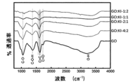
FTIRスペクトル
図1に示すように、GOフィルムのFTIRスペクトルには、カルボン酸やカルボニル部分のC‐O、C‐OH、C=C、C=Oに関連するピークが存在する。これらのピークは、主にシートエッジに沿って存在するが、グラフェンシートの基底面にも存在し、幅広いO‐Hピークも存在する。興味深いことに、C‐O、C‐O‐H、C=Oの各官能基に対応するピークは、KIの量を増やすと大幅に減少し、GOとKIの重量比が1:2になるとほぼ完全に消失した。このことから、水中に懸濁したGOと溶解したKIを組み合わせるだけで、GOの化学的還元が促進され、得られた懸濁液は主にprGOで構成されていることがわかった。
Example 2
FTIR Spectra As shown in Figure 1, the FTIR spectrum of the GO film contains peaks associated with the carboxylic acid and carbonyl moieties C-O, C-OH, C=C, and C=O. These peaks are mainly along the sheet edges, but also present on the basal planes of the graphene sheets, as well as a broad O-H peak. Interestingly, the peaks corresponding to the C-O, C-O-H, and C=O functional groups were significantly reduced with increasing amounts of KI, and almost completely disappeared at a GO to KI weight ratio of 1:2. This indicates that the combination of suspended GO and dissolved KI in water alone is sufficient to promote the chemical reduction of GO, with the resulting suspension being composed mainly of prGO.
ラマン分光法
KIとGOの相互作用を更に理解するために、ラマン分光測定を行った。10%出力のHeNe(632.8nm)レーザーを装備した「Renishaw Confocal micro‐Raman Spectrometer」を用いて、水を除去して得られたprGOおよびKI膜の液体組成物から得られた乾燥層のラマンスペクトルを得た。レーザーのスポットサイズは1μmで、100~3200の波数で10秒間の延長スキャンを行った。バックグラウンドを除去した後、データを最大強度で割ってスペクトルの強度を正規化した。PeakFitソフトウェアパッケージを用いてピークフィッティングを行い、フィッティングされた曲線を用いて、主要なGバンドとDバンドの強度比(ID/IG)を決定した。その結果を図2にまとめた。
Raman spectroscopy To further understand the interaction between KI and GO, Raman spectroscopy measurements were performed. A Renishaw Confocal micro-Raman Spectrometer equipped with a HeNe (632.8 nm) laser at 10% power was used to obtain Raman spectra of the dried layers obtained from the liquid compositions of prGO and KI membranes obtained by removing the water. The laser spot size was 1 μm and extended scans of 10 s duration were performed from 100 to 3200 wavenumbers. After background subtraction, the intensity of the spectra was normalized by dividing the data by the maximum intensity. Peak fitting was performed using the PeakFit software package and the fitted curve was used to determine the intensity ratio of the main G band to the D band (I D /I G ). The results are summarized in Figure 2.
各スペクトルには、1600cm-1付近に、GO構造のグラファイト化の指標である、炭素環および炭素鎖のすべてのペアのsp2原子の結合伸張に対応するGバンドと、1350cm-1付近に、活性化に欠陥/無秩序を必要とする炭素環のsp2原子のブリージングモードに起因するDバンドが存在した。KIとGOを組み合わせることで、ID/IG比(試料の少なくとも5つの異なる領域で測定し平均化したもの)は1.21から1.13に減少した。この比率の低下は、官能基の除去とC=C結合の回復によるものと考えられる。これらの結果は、KIによってGOが部分的に還元されてprGOになったことを示唆するFTIR分析結果と一致する。 Each spectrum contained a G band at around 1600 cm -1 , which corresponds to the bond stretching of sp2 atoms of all pairs of carbon rings and carbon chains, indicative of the graphitization of the GO structure, and a D band at around 1350 cm -1 , which is due to the breathing mode of sp2 atoms of carbon rings, which require defects/disorder for activation. By combining KI with GO, the I D /I G ratio (measured and averaged over at least five different regions of the sample) decreased from 1.21 to 1.13. This decrease in ratio can be attributed to the removal of functional groups and the restoration of C=C bonds. These results are consistent with the FTIR analysis, which suggests that KI partially reduced GO to prGO.
X線光電子分光法(XPS)
XPSは、FTIRとラマン分光法の観察結果を裏付けるものである。試料のO/C比は、サーベイスペクトル(survey spectra)から決定した。GO、prGO、および紫外線照射によって生じたGOの還元体のシグナルを分離するため、XPS分析の前にKIを含む試料を十分に洗浄した。図3および図4は、各試料の高分解能C1sスペクトルである。
X-ray photoelectron spectroscopy (XPS)
XPS confirms the observations from FTIR and Raman spectroscopy. The O/C ratios of the samples were determined from survey spectra. To separate the signals, the samples containing KI were thoroughly washed prior to XPS analysis. Figures 3 and 4 show the high-resolution C1s spectra of each sample.
ピークが近接しているため、KIのC1sスペクトルにはK2pダブレットも含まれている。洗浄後にこのダブレットが除去されていることから、洗浄プロセスとKイオンの除去が有効であることがわかる。GO層のO/C比は0.407で、そのC1sスペクトルには、グラフで示したようにC=O、C‐O、C‐C/C=C基に属するピークが含まれていた。溶解したKIと懸濁したGOを組み合わせるだけでO/C比が0.341まで低下することがわかり、このプロセスがエポキシや水酸基のようなC‐O基を主に除去することでGOを還元していることがわかる。 Due to the close proximity of the peaks, the C1s spectrum of KI also contains a K2p doublet. This doublet is removed after washing, indicating that the washing process and removal of K ions are effective. The O/C ratio of the GO layer is 0.407 and its C1s spectrum contains peaks belonging to C=O, C-O, and C-C/C=C groups as shown in the graph. We find that the O/C ratio drops to 0.341 simply by combining dissolved KI with suspended GO, indicating that the process reduces GO primarily by removing C-O groups such as epoxy and hydroxyl groups.
X線回折(XRD)
Bruker D2 phaser 回折計を用いて、30kV、10mAの電圧でCu‐Kα線を照射し、走査速度2°/分、工程サイズ0.02°で、乾燥層のX線回折(XRD)分析を行い、KIによるGOの還元を更に確認した。未変性(pristine)GOは、GOの(001)面に起因する約10.7°の2θのピークを1つだけ示した(図5)。これは、GOの(001)面の間にK+またはI-イオンがインターカレートし、層間距離が長くなったためと考えられる。更に、約24~25°に小さなこぶが現れたが、これは特徴的なrGO(002)ピークであると考えられる。残りのピークは、未反応のKI結晶に属するものであることがわかった。
X-ray diffraction (XRD)
X-ray diffraction (XRD) analysis of the dried layer was performed using a Bruker D2 phaser diffractometer with Cu-Kα radiation at a voltage of 30 kV, 10 mA, a scan rate of 2°/min, and a step size of 0.02° to further confirm the reduction of GO by KI. The pristine GO showed only one peak at 2θ of about 10.7°, which was attributed to the (001) plane of GO (Figure 5). This was attributed to the intercalation of K + or I - ions between the (001) planes of GO, which increased the interlayer distance. In addition, a small hump appeared at about 24-25°, which was believed to be the characteristic rGO (002) peak. The remaining peaks were found to belong to unreacted KI crystals.
電気シート抵抗
電気シート抵抗の測定は、1mm幅の4点プローブを用い、Keithley電位計(モデル2400、米国)で行った。その結果、KIの添加によりシート抵抗が大幅に減少していることがわかった。乾燥したGO層のシート抵抗は約1.4GΩ/sq.であったが、GO:KI(1:2)のシート抵抗は約24.7MΩ/sq.以下低下した。測定における残留KIの影響を排除するため、フィルムをRO水で広範囲に洗浄し、真空オーブンで乾燥させた。洗浄したフィルムのシート抵抗値は約25.5MΩ/sq.で、未洗浄のフィルムと非常に近い値であった。これらの結果は、KIとの組み合わせによるprGOの形成とC=C結合の回復を示すさらなる証拠である。
Electrical Sheet Resistance Electrical sheet resistance measurements were performed with a Keithley electrometer (Model 2400, USA) using a 1 mm wide 4-point probe. The results showed that the addition of KI significantly reduced the sheet resistance. The sheet resistance of the dried GO layer was about 1.4 GΩ/sq., while the sheet resistance of the GO:KI (1:2) was reduced to about 24.7 MΩ/sq. To eliminate the influence of residual KI on the measurements, the films were extensively washed with RO water and dried in a vacuum oven. The sheet resistance value of the washed film was about 25.5 MΩ/sq., very close to that of the unwashed film. These results are further evidence of the formation of prGO and restoration of C=C bonds upon combination with KI.
(実施例3)
液体組成物の偏光顕微鏡検査
prGOおよびヨウ化物を含む液体組成物は、液晶の光学特性を示している。懸濁液の液状地殻性を証明するために、CRI社のAbrio偏光イメージングシステムを装着した倒立型Leica DM IRB顕微鏡を用いて偏光顕微鏡検査を行った。画像は、従来のコンペンセーターの代わりに、直線偏光子、アナライザー、2枚の可変電気光学リターダープレートからなる複屈折セットアップモードで撮影した。試料を透過した偏光は、従来の顕微鏡用スライドガラスにセットされ、アナライザーを通過した後、高感度CCDカメラに取り込まれる。撮影された信号は、デジタル画像処理システムを用いて順次処理されて、光遅延を生じ、異方性材料の軸方向の画像を遅らせた。1:2のGO:KI比を有するrGO懸濁液をこの目的のために使用した。
Example 3
Polarized light microscopy of liquid compositions Liquid compositions containing prGO and iodide show optical properties of liquid crystals. To prove the liquid crustal nature of the suspensions, polarized light microscopy was performed using an inverted Leica DM IRB microscope fitted with a CRI Abrio polarized imaging system. Images were taken in a birefringence setup mode consisting of a linear polarizer, an analyzer and two variable electro-optical retarder plates instead of a conventional compensator. The polarized light transmitted through the sample is set on a conventional microscope slide and, after passing through an analyzer, is captured on a highly sensitive CCD camera. The captured signal was subsequently processed using a digital image processing system to produce an optical delay and retard the axial image of the anisotropic material. A rGO suspension with a GO:KI ratio of 1:2 was used for this purpose.
偏光顕微鏡の顕微鏡写真(図示せず)からわかったように、prGOおよびヨウ化物を含む液体組成物は光遅延を示す。この遅延は、異方性材料の特徴である面内および面外の光学的位相差により発生する。更に、prGOのプレートレットは好ましい方向に配向しており、その好ましい方向は試料全体で空間的に変化し、典型的なネマティック液晶ドメインを形成していた。この分析結果は、液体組成物の液晶性を示している。 As seen from polarized light microscopy micrographs (not shown), the liquid composition containing prGO and iodide exhibits optical retardation. This retardation arises from the in-plane and out-of-plane optical retardation characteristic of anisotropic materials. Furthermore, the prGO platelets are aligned in a preferred direction that varies spatially throughout the sample, forming typical nematic liquid crystal domains. This analysis indicates the liquid crystalline nature of the liquid composition.
(実施例4)
液状組成物の安定性
GOは水に非常に安定した懸濁液を作るが、安定した水性のprGO懸濁液を得ることは困難である。そのため、prGOを含む液体組成物の安定性を調べることが重要である。安定性の指標として、液体組成物のゼータ電位をBrookhaven Nanobrook Omni Zeta Potential Analyzerを用いて測定した。各試料の5回の測定からの平均値で、25℃で20回の相サイクルからなる各測定値を取った。測定には、気泡ができないようにポリスチレン製のキュベットにパラジウム電極を浸した。ポリスチレン製キュベットの経路長を1.0cmとし、Smoluchowski(スモルフコフスキー)近似法:
![]()
を用いてゼータ電位ζを求めた。
Example 4
Stability of the liquid composition
Although GO forms a very stable suspension in water, it is difficult to obtain a stable aqueous prGO suspension. Therefore, it is important to investigate the stability of liquid compositions containing prGO. As an indicator of stability, the zeta potential of the liquid compositions was measured using a Brookhaven Nanobrook Omni Zeta Potential Analyzer. Each measurement consisted of 20 phase cycles at 25°C, with the average value from five measurements for each sample. For the measurements, the palladium electrode was immersed in a polystyrene cuvette to avoid air bubbles. The path length of the polystyrene cuvette was set to 1.0 cm, and the Smoluchowski approximation method:
![]()
The zeta potential ζ was calculated using
GOにKIを添加すると、最初にゼータ電位が上昇した(図6)。これは、最初に懸濁液の安定性を低下させるいくつかのprGOが形成されたことに起因すると考えられる。KIの添加量を更に増やすと、ゼータ電位は低下し始め、純粋なGO懸濁液のそれよりも低くなり、安定性が向上したことを示している。KIの添加と官能基のさらなる除去により、高い静電的負電荷は、K+イオンの存在による正味の正電荷によって遮蔽される可能性がある。一方、I-イオンによる静電的な反発は、水相中のprGOの効果的な分散を助け、ゼータ電位の低下と懸濁液の安定性の向上につながると考えられる。 The addition of KI to GO initially increased the zeta potential (Fig. 6). This could be attributed to the formation of some prGO that initially reduced the stability of the suspension. With further increase in the amount of KI added, the zeta potential began to decrease and became lower than that of the pure GO suspension, indicating improved stability. With the addition of KI and further removal of functional groups, the high electrostatic negative charge could be shielded by the net positive charge due to the presence of K + ions. Meanwhile, the electrostatic repulsion by I- ions could help the effective dispersion of prGO in the aqueous phase, leading to a decrease in the zeta potential and improved suspension stability.
懸濁液の安定性は、更に長期間の保存によって物理的に評価された。GO:KIの重量比が1:2のprGO液体組成物を、好適な量のRO水を加えて10-2g/リットルの濃度になるように異なる範囲で希釈した。懸濁液は4ヶ月間安定しており、prGOの目に見える浮遊または沈降は示さなかった。 The stability of the suspension was further physically evaluated by long-term storage. The prGO liquid composition with a weight ratio of 1:2 GO:KI was diluted in different ranges to a concentration of 10 −2 g/liter by adding an appropriate amount of RO water. The suspension was stable for 4 months and showed no visible floating or settling of prGO.
(実施例5)
紫外線照射
prGO(GO:KI 1:2)層を更に還元するために、乾燥したコーティング剤をUVランプ(55W、Philips、TUV PL-L 55W/4P)を用いて254nmのUV光に22.4mW/cm2の強度で17時間照射した。
Example 5
UV irradiation To further reduce the prGO (GO:KI 1:2) layer, the dried coatings were irradiated with 254 nm UV light using a UV lamp (55 W, Philips, TUV PL-L 55W/4P) at an intensity of 22.4 mW/ cm2 for 17 h.
紫外線照射による還元後、XRDパターンのGOピークは完全に消失し(図5)、ラマンスペクトルの特徴的なID/IG比は1.07まで更に減少した(図2)。更に、XPS分析では、C‐O基が除去され、O/C比が0.177に減少したことで、GOのUV還元が確認されました(図4(b))。注目すべきは、XPS分析の結果、UVC光で還元された純粋なGO膜の方が、より大きなO/C比(0.233)を示したことである(図4(c))。これらの結果は、GOにKIを添加することでGOが部分的に還元され、UV照射による還元効率が向上したことを示している。更に、試料の高分解能I 3d XPSスキャン(図7)から、Iは特に紫外線還元時にprGOと結合を形成し、IドープprGOを形成していることがわかった。図7aでは、右側のピークの半値全幅(FWHM)は1.0983eVである。図7bでは、右側のピークは、半値幅が1.3262(面積77.03%)と1.4(面積22.97%)の2つのピークに分解できる。図7cでは、右側のピークは、FWHMが1.2408(89.04%の面積)と1.3861(10.96%の面積)の2つのピークに分解される。図7a、図7b、図7cのx軸は結合エネルギー(eV)である。 After reduction by UV irradiation, the GO peak in the XRD pattern completely disappeared (Fig. 5), and the characteristic I D /I G ratio in the Raman spectrum further decreased to 1.07 (Fig. 2). Furthermore, XPS analysis confirmed the UV reduction of GO by removing the C-O groups and decreasing the O/C ratio to 0.177 (Fig. 4(b)). Of note, the XPS analysis showed that the pure GO film reduced by UVC light showed a larger O/C ratio (0.233) (Fig. 4(c)). These results indicate that the addition of KI to GO partially reduced GO and improved the reduction efficiency by UV irradiation. Furthermore, the high-resolution I 3d XPS scan of the sample (Fig. 7) showed that I formed bonds with prGO, especially during UV reduction, to form I-doped prGO. In Fig. 7a, the full width at half maximum (FWHM) of the right peak is 1.0983 eV. In Figure 7b, the right peak can be resolved into two peaks with FWHMs of 1.3262 (area 77.03%) and 1.4 (area 22.97%). In Figure 7c, the right peak can be resolved into two peaks with FWHMs of 1.2408 (area 89.04%) and 1.3861 (area 10.96%). The x-axis in Figures 7a, 7b, and 7c is binding energy (eV).
また、UV処理したrGOフィルムのシート抵抗は、~24.7MΩ/sq.から~1.1MΩ/sq.へと、約22分の1に大幅に減少した。 In addition, the sheet resistance of the UV-treated rGO film was significantly reduced by about 22 times, from ~24.7 MΩ/sq. to ~1.1 MΩ/sq.
(実施例6)
スーパーキャパシタの作製
上記の実施例に記載された手順で得られた形態の還元型GOを使用して、二重層スーパーキャパシタデバイスを作製した。最初の還元型GOを金属集電体にロッドコートして電極を作製した。作製した電極の面荷重は、10μgの加重精度を持つマイクロ天秤を用いて測定したところ、約7mg/cm2であり、これは2.3mg/cm2のグラファイト面荷重に相当する。この電極は、17時間のUV照射によって更に還元され、一般的なパウチセルの構成でパッケージングされた。この構成では、一対の折り畳まれた電極が、周囲の条件でLi2SO4電解液に浸されたセパレータによって分離されている。
Example 6
Supercapacitor Fabrication A double-layer supercapacitor device was fabricated using reduced GO in the form obtained by the procedure described in the above examples. The initial reduced GO was rod-coated onto a metal current collector to fabricate an electrode. The surface loading of the fabricated electrode was approximately 7 mg/ cm2 , as measured using a microbalance with a load accuracy of 10 μg, which corresponds to a graphite surface loading of 2.3 mg/ cm2 . The electrode was further reduced by UV irradiation for 17 hours and packaged in a typical pouch cell configuration, in which a pair of folded electrodes are separated by a separator immersed in Li2SO4 electrolyte at ambient conditions.
走査型電子顕微鏡(SEM、FEI Nova NanoSEM 450 FEG)を用いて、電極の形態とrGO内の残留KI結晶の分布を調べた。断面のSEM顕微鏡写真から、KI結晶(丸い粒子)が、ラザニア型構造を形成するrGOのグラファイト層の間に分布していることが明らかになった(図8)。このようにグラファイトシートの間にヨウ化物が分布していると、電極の抵抗が大幅に減少し、定格容量が向上することが期待される。 Scanning electron microscopy (SEM, FEI Nova NanoSEM 450 FEG) was used to study the electrode morphology and the distribution of residual KI crystals in the rGO. Cross-sectional SEM micrographs revealed that KI crystals (round particles) were distributed between the graphite layers of rGO forming a lasagna-type structure (Figure 8). Such iodide distribution between the graphite sheets is expected to significantly reduce the electrode resistance and improve the rated capacity.
(実施例7)
スーパーキャパシタデバイスの性能を、BioLogic社のポテンショスタットで評価した。開放電位(OCP)を少なくとも1時間モニターし、経時的な安定性を確認した。OCPの変動が1000秒間で10mV以内であれば、電気化学的測定を行う前に安定した電位とみなした。電極のサイクリックボルタモグラム(CV曲線)は、さまざまな走査速度(5mV/s~100mV/s)で、試験電位範囲内で記録した。測定は、各走査速度で50サイクル繰り返した。異なる走査速度でのスーパーキャパシタデバイスのCVボルタモグラムを図9に示す。
(Example 7)
The performance of the supercapacitor device was evaluated with a BioLogic potentiostat. The open circuit potential (OCP) was monitored for at least 1 h to check the stability over time. A variation in OCP within 10 mV for 1000 s was considered as a stable potential before electrochemical measurements were performed. Cyclic voltammograms (CV curves) of the electrodes were recorded at various scan rates (5 mV/s to 100 mV/s) within the test potential range. The measurements were repeated for 50 cycles at each scan rate. The CV voltammograms of the supercapacitor device at different scan rates are shown in Figure 9.
このボルタモグラムは、走査速度100mV/秒まで長方形を呈しており、これは電極の典型的な二重層容量の挙動と、その優れた評価能力を示している(図9(a))。この電極の5mV/秒での比誘電率は約83F/gであった。図9(b)は、電極の走査速度依存性比容量をまとめたものである。この電極は、走査速度の増加に伴って良好な容量維持率を示し、容量維持率は約70%であった。更に、この電極は、パウチセル構成において、11.5Wh/kgという高いエネルギー密度と2800W/kgという大きな電力密度を示した。 The voltammogram exhibited a rectangular shape up to a scan rate of 100 mV/s, indicating the typical double layer capacitance behavior of the electrode and its excellent characterization capability (Figure 9(a)). The relative dielectric constant of the electrode at 5 mV/s was about 83 F/g. Figure 9(b) summarizes the scan rate-dependent specific capacitance of the electrode. The electrode showed good capacity retention with increasing scan rate, with a capacity retention of about 70%. Furthermore, the electrode showed a high energy density of 11.5 Wh/kg and a large power density of 2800 W/kg in a pouch cell configuration.
電気化学インピーダンス分光法(EIS)試験は、開回路電位に10mVの振幅で正弦波の電位摂動を加えて行った。インピーダンス応答は、1MHzから10MHzの間の周波数で測定し、周波数の10年ごとに6点を記録した。電気化学データの再現性を調べるため、すべての電気化学実験を少なくとも3回繰り返した。図9(c)は、電極のナイキストプロットを示している。このプロットは、高周波の小さな半円と、低周波領域の高傾斜の直線から構成されている。高周波の小さな半円は、非常に小さな電荷移動抵抗を表し、低周波の高い傾きの直線は、電極の容量性を表している。ナイキストプロットとインピーダンスの実部(x軸)との交点から推定される電極の抵抗値は非常に小さく、約60MΩであることがわかった。 Electrochemical impedance spectroscopy (EIS) tests were performed by applying a sinusoidal potential perturbation with an amplitude of 10 mV to the open circuit potential. The impedance response was measured at frequencies between 1 MHz and 10 MHz, and six points were recorded per decade of frequency. To check the reproducibility of the electrochemical data, all electrochemical experiments were repeated at least three times. Figure 9(c) shows the Nyquist plot of the electrode. The plot consists of a small semicircle at high frequency and a straight line with a high slope in the low frequency region. The small semicircle at high frequency represents a very small charge transfer resistance, and the straight line with a high slope at low frequency represents the capacitive nature of the electrode. The resistance of the electrode, estimated from the intersection of the Nyquist plot with the real part of the impedance (x-axis), was found to be very small, about 60 MΩ.
さまざまな電流密度(0.2A/g、0.5A/g、1A/g、2A/g)で測定した電極の定電流充放電曲線を図10に示す。すべての電流密度において、全電位範囲にわたって一定の傾きを持つ対称的で直線的な充放電プロファイルが得られ、ほぼ完全な二重層容量性の挙動を示している。更に、充放電曲線では非常に小さなIRドロップが観察され、デバイスの等価直列抵抗(ESR)が小さい(約400MΩ)ことを示しており、インピーダンス測定(~300MΩ、Nyquist(ナイキスト)線図の低周波領域の接線とインピーダンスの実部(x軸)との交点から推定)と一致していた。 Galvanostatic charge-discharge curves of the electrode measured at various current densities (0.2 A/g, 0.5 A/g, 1 A/g, 2 A/g) are shown in Figure 10. At all current densities, symmetrical and linear charge-discharge profiles with constant slope over the entire potential range were obtained, indicating nearly perfect double-layer capacitive behavior. Furthermore, very small IR drops were observed in the charge-discharge curves, indicating that the equivalent series resistance (ESR) of the device is small (~400 MΩ), consistent with impedance measurements (~300 MΩ, estimated from the intersection of the tangent line in the low-frequency region of the Nyquist plot with the real part of the impedance (x-axis)).
(実施例8)
1Vおよび2Vのスーパーキャパシタデバイスを作製し、後者は2つの1Vデバイスを直列に接続して得た。図11は、2VのデバイスのCV曲線と充放電挙動をまとめたもので、同じ電流28.8mAで測定した1VのスーパーキャパシタのCV曲線と比較している。2Vのスーパーキャパシタは、1Vのスーパーキャパシタと同様の特性、すなわち、長方形のCVカーブと対称的で直線的な充放電プロファイルを示した。
(Example 8)
1 V and 2 V supercapacitor devices were fabricated, the latter obtained by connecting two 1 V devices in series. Figure 11 summarizes the CV curves and charge/discharge behavior of the 2 V device and compares it with the CV curve of the 1 V supercapacitor measured at the same current of 28.8 mA. The 2 V supercapacitor showed similar characteristics to the 1 V supercapacitor, i.e., a rectangular CV curve and a symmetrical linear charge/discharge profile.
本明細書中および請求項において、文脈上他の意味に解すべき場合を除き、「~を含む(comprise)」という語、および「comprises」や「comprising」などの変化形は、記載された完全体(integer)または工程、または完全体または工程のグループを含むことを意味するが、他の完全体または工程、または完全体または工程のグループを除外することを意味しないと理解される。 In this specification and claims, unless the context requires otherwise, the word "comprise" and variations such as "comprises" and "comprising" are understood to mean the inclusion of a stated integer or step or group of integers or steps, but not the exclusion of other integers or steps or groups of integers or steps.
本明細書中では、先行刊行物(またはそれから派生した情報)または既知の事項を参照しているが、その先行刊行物物(またはそれから派生した情報)または既知の事項が、本明細書が関連する技術分野における一般常識の一部を形成していることを認めたり、承認したり、何らかの形で示唆したりするものではなく、かつそうすべきではない。 The reference in this specification to prior publications (or information derived therefrom) or known matters is not, and should not be, an acknowledgement, admission or in any way suggestion that the prior publications (or information derived therefrom) or known matters form part of the common general knowledge in the art to which this specification pertains.
Claims (18)
液体媒体にてGOを懸濁させ、ヨウ化物を溶解させて、それによって、溶解したヨウ化物がGOを部分的に還元して、部分的に還元されたGO(prGO)および溶解したヨウ化物を含む液体組成物を得る工程、
液体組成物から液体媒体を除去して、prGOおよびヨウ化物を含むグラファイト層を形成する工程、および
グラファイト層に紫外線を照射して、prGOを更に還元し、還元型酸化グラフェンを提供する工程
を含む、方法。 1. A method for reducing graphene oxide (GO), comprising:
suspending GO in a liquid medium and dissolving iodide, whereby the dissolved iodide partially reduces the GO to obtain a liquid composition comprising partially reduced GO (prGO) and dissolved iodide;
removing the liquid medium from the liquid composition to form a graphite layer comprising prGO and iodide; and irradiating the graphite layer with ultraviolet light to further reduce the prGO and provide reduced graphene oxide.
Applications Claiming Priority (3)
| Application Number | Priority Date | Filing Date | Title |
|---|---|---|---|
| AU2019901781 | 2019-05-24 | ||
| AU2019901781A AU2019901781A0 (en) | 2019-05-24 | Reduced Graphene Oxide | |
| PCT/AU2020/050507 WO2020237289A1 (en) | 2019-05-24 | 2020-05-22 | Reduced graphene oxide |
Publications (2)
| Publication Number | Publication Date |
|---|---|
| JP2022534222A JP2022534222A (en) | 2022-07-28 |
| JP7594792B2 true JP7594792B2 (en) | 2024-12-05 |
Family
ID=73552137
Family Applications (1)
| Application Number | Title | Priority Date | Filing Date |
|---|---|---|---|
| JP2021569357A Active JP7594792B2 (en) | 2019-05-24 | 2020-05-22 | Reduced graphene oxide |
Country Status (7)
| Country | Link |
|---|---|
| US (1) | US12325636B2 (en) |
| EP (1) | EP3976532A4 (en) |
| JP (1) | JP7594792B2 (en) |
| KR (1) | KR102915897B1 (en) |
| CN (1) | CN114174221A (en) |
| AU (1) | AU2020282379A1 (en) |
| WO (1) | WO2020237289A1 (en) |
Families Citing this family (2)
| Publication number | Priority date | Publication date | Assignee | Title |
|---|---|---|---|---|
| JP7558569B2 (en) * | 2021-04-15 | 2024-10-01 | 国立研究開発法人産業技術総合研究所 | Graphene laminate and method for producing same |
| CN118419917B (en) * | 2023-07-19 | 2024-12-10 | 微智帆途科技(苏州)有限公司 | Graphene reduced by graphene oxide, graphene film and preparation method of graphene film |
Citations (3)
| Publication number | Priority date | Publication date | Assignee | Title |
|---|---|---|---|---|
| JP2014009104A (en) | 2012-06-27 | 2014-01-20 | Unitika Ltd | Graphene-dispersed liquid and preparation method thereof |
| JP2016222526A (en) | 2015-05-29 | 2016-12-28 | 株式会社半導体エネルギー研究所 | Film formation method and element |
| WO2018044762A1 (en) | 2016-08-31 | 2018-03-08 | Rutgers, The State University Of New Jersey | High-quality graphene and method of producing same via microwave reduction of graphene oxide |
Family Cites Families (11)
| Publication number | Priority date | Publication date | Assignee | Title |
|---|---|---|---|---|
| US20110079748A1 (en) * | 2009-10-02 | 2011-04-07 | Ruoff Rodney S | Exfoliation of Graphite Oxide in Propylene Carbonate and Thermal Reduction of Resulting Graphene Oxide Platelets |
| CN103065813B (en) | 2012-12-20 | 2016-03-30 | 中国科学技术大学 | The preparation method of electrode of super capacitor and application thereof |
| KR20140119952A (en) | 2013-03-29 | 2014-10-13 | 도시바삼성스토리지테크놀러지코리아 주식회사 | Method of manufacturing Graphene using a plurality of light source |
| CN103754866B (en) * | 2014-01-23 | 2016-02-03 | 四川材料与工艺研究所 | The method of graphene film is prepared in a kind of iron iodide acidic solution reduction |
| US9840782B2 (en) * | 2014-07-17 | 2017-12-12 | Rochester Institute Of Technology | Electrochemical process for producing graphene, graphene oxide, metal composites, and coated substrates |
| KR101733861B1 (en) * | 2015-04-28 | 2017-05-08 | 성균관대학교산학협력단 | Method of manufacturing a reduced-graphene oxide |
| US20210134537A1 (en) | 2017-03-01 | 2021-05-06 | B.G. Negev Technologies And Applications Ltd., At Ben-Gurion University | An electrode and an electrochemical capacitor comprising the electrode |
| CN107610804B (en) * | 2017-08-23 | 2020-12-29 | 北京师范大学 | Method for preparing photoresist-reduced graphene oxide composite conductive material |
| CN107876087B (en) * | 2017-11-03 | 2019-12-17 | 山东大学 | Preparation of methylamine lead iodine-reduced graphene oxide composite photocatalytic material and its application in photocatalytic hydrogen production |
| CN108975316B (en) * | 2018-09-26 | 2020-02-04 | 西北有色金属研究院 | Preparation method of graphene film |
| CN109956465B (en) * | 2019-03-22 | 2020-09-08 | 北京航空航天大学 | Preparation method of long-chain conjugated pi-bond crosslinked ultra-tough high-conductivity graphene composite film |
-
2020
- 2020-05-22 JP JP2021569357A patent/JP7594792B2/en active Active
- 2020-05-22 KR KR1020217042326A patent/KR102915897B1/en active Active
- 2020-05-22 EP EP20815302.3A patent/EP3976532A4/en active Pending
- 2020-05-22 WO PCT/AU2020/050507 patent/WO2020237289A1/en not_active Ceased
- 2020-05-22 CN CN202080053351.2A patent/CN114174221A/en active Pending
- 2020-05-22 US US17/613,755 patent/US12325636B2/en active Active
- 2020-05-22 AU AU2020282379A patent/AU2020282379A1/en active Pending
Patent Citations (3)
| Publication number | Priority date | Publication date | Assignee | Title |
|---|---|---|---|---|
| JP2014009104A (en) | 2012-06-27 | 2014-01-20 | Unitika Ltd | Graphene-dispersed liquid and preparation method thereof |
| JP2016222526A (en) | 2015-05-29 | 2016-12-28 | 株式会社半導体エネルギー研究所 | Film formation method and element |
| WO2018044762A1 (en) | 2016-08-31 | 2018-03-08 | Rutgers, The State University Of New Jersey | High-quality graphene and method of producing same via microwave reduction of graphene oxide |
Non-Patent Citations (1)
| Title |
|---|
| LI Jianwei et al,Novel iodine-doped reduced graphene oxide anode for sodium ion batteries,RSC Advances,2017年,Vol. 7,No. 87,p.55060-55066,DOI: 10.1039/c7ra09349g |
Also Published As
| Publication number | Publication date |
|---|---|
| JP2022534222A (en) | 2022-07-28 |
| KR102915897B1 (en) | 2026-01-20 |
| US12325636B2 (en) | 2025-06-10 |
| WO2020237289A1 (en) | 2020-12-03 |
| CN114174221A (en) | 2022-03-11 |
| EP3976532A1 (en) | 2022-04-06 |
| US20220242735A1 (en) | 2022-08-04 |
| KR20220011726A (en) | 2022-01-28 |
| AU2020282379A1 (en) | 2022-01-20 |
| EP3976532A4 (en) | 2023-11-29 |
Similar Documents
| Publication | Publication Date | Title |
|---|---|---|
| Murali et al. | A review on MXenes: new-generation 2D materials for supercapacitors | |
| Liu et al. | Sulfonic-Group-Grafted Ti3C2T x MXene: A Silver Bullet to Settle the Instability of Polyaniline toward High-Performance Zn-Ion Batteries | |
| Sohan et al. | Review on MXene synthesis, properties, and recent research exploring electrode architecture for supercapacitor applications | |
| Zhang et al. | A novel PMA/PEG-based composite polymer electrolyte for all-solid-state sodium ion batteries | |
| Ju et al. | Cationic interfacial layer toward a LiF-enriched interphase for stable Li metal batteries | |
| US11450487B2 (en) | Humic acid-based supercapacitors | |
| Huang et al. | Permselective graphene oxide membrane for highly stable and anti-self-discharge lithium–sulfur batteries | |
| Li et al. | Controlling the formation of rodlike V2O5 nanocrystals on reduced graphene oxide for high-performance supercapacitors | |
| Zhu et al. | Graphene oxide/polypyrrole nanocomposites: one-step electrochemical doping, coating and synergistic effect for energy storage | |
| US10068716B2 (en) | Graphene-ionic liquid composites | |
| JP6952702B2 (en) | Supercapacitor electrodes with highly oriented and tightly packed graphene sheets and manufacturing process | |
| Rath et al. | Reduced graphene oxide paper based nanocomposite materials for flexible supercapacitors | |
| Pham et al. | Facile electrodeposition of reduced graphene oxide hydrogels for high-performance supercapacitors | |
| KR20200003867A (en) | Rolled Supercapacitors and Production Process | |
| Shen et al. | Recent advances in two-dimensional MXenes for zinc-ion batteries | |
| Ronnasi et al. | ⍺-NSA doped PPy@ Ti3C2T x hybrid material as a high-performance supercapacitor electrode | |
| JP7594792B2 (en) | Reduced graphene oxide | |
| Zheng et al. | 3D porous reduced graphene cathode and non-corrosive electrolyte for long-life rechargeable aluminum batteries | |
| Maddukuri et al. | Na0. 44MnO2/polyimide aqueous Na-ion batteries for large energy storage applications | |
| Kim et al. | Utilization of 2D materials in aqueous zinc ion batteries for safe energy storage devices | |
| Chen et al. | Dendrite-free Mg-MOF-based all-solid-state lithium metal batteries with superior cycle life: X.-D. Chen et al. | |
| Zhao et al. | Accordion frameworks enable free‐standing, high Si content anode for Li‐ion batteries | |
| Kim et al. | Inhibiting polysulfide shuttle and enhancing polysulfide redox: Conductive 2D metal-organic framework coated separators for lithium-sulfur batteries | |
| Yan et al. | Application of GO anchored mediator in a polymer electrolyte membrane for high-rate solid-state supercapacitors | |
| Al-Bujasim et al. | A tripartite composite incorporating nitrogen-doped graphene oxide, polypyrrole, and silica for lithium-ion battery anodes |
Legal Events
| Date | Code | Title | Description |
|---|---|---|---|
| A621 | Written request for application examination |
Free format text: JAPANESE INTERMEDIATE CODE: A621 Effective date: 20230510 |
|
| RD03 | Notification of appointment of power of attorney |
Free format text: JAPANESE INTERMEDIATE CODE: A7423 Effective date: 20240513 |
|
| A977 | Report on retrieval |
Free format text: JAPANESE INTERMEDIATE CODE: A971007 Effective date: 20240521 |
|
| A131 | Notification of reasons for refusal |
Free format text: JAPANESE INTERMEDIATE CODE: A131 Effective date: 20240604 |
|
| A521 | Request for written amendment filed |
Free format text: JAPANESE INTERMEDIATE CODE: A523 Effective date: 20240806 |
|
| TRDD | Decision of grant or rejection written | ||
| A01 | Written decision to grant a patent or to grant a registration (utility model) |
Free format text: JAPANESE INTERMEDIATE CODE: A01 Effective date: 20241022 |
|
| A61 | First payment of annual fees (during grant procedure) |
Free format text: JAPANESE INTERMEDIATE CODE: A61 Effective date: 20241118 |
|
| R150 | Certificate of patent or registration of utility model |
Ref document number: 7594792 Country of ref document: JP Free format text: JAPANESE INTERMEDIATE CODE: R150 |