JP7592425B2 - Processing method, processing device, mold manufacturing method, resin molded product manufacturing method, program, and recording medium - Google Patents
Processing method, processing device, mold manufacturing method, resin molded product manufacturing method, program, and recording medium Download PDFInfo
- Publication number
- JP7592425B2 JP7592425B2 JP2020132527A JP2020132527A JP7592425B2 JP 7592425 B2 JP7592425 B2 JP 7592425B2 JP 2020132527 A JP2020132527 A JP 2020132527A JP 2020132527 A JP2020132527 A JP 2020132527A JP 7592425 B2 JP7592425 B2 JP 7592425B2
- Authority
- JP
- Japan
- Prior art keywords
- region
- processing
- head
- irradiation
- recesses
- Prior art date
- Legal status (The legal status is an assumption and is not a legal conclusion. Google has not performed a legal analysis and makes no representation as to the accuracy of the status listed.)
- Active
Links
Images


Landscapes
- Laser Beam Processing (AREA)
- Moulds For Moulding Plastics Or The Like (AREA)
Description
本発明は、加工方法、加工装置、金型の製造方法、樹脂成形物の製造方法、等に関する。特に、外観面の光沢を制御するために微細な表面構造を備えた樹脂成形品を製造するのに寄与する技術に関する。 The present invention relates to a processing method, a processing device, a method for manufacturing a mold, a method for manufacturing a resin molded product, etc. In particular, the present invention relates to a technology that contributes to the manufacturing of a resin molded product with a fine surface structure in order to control the gloss of the exterior surface.
プリンタをはじめとする各種装置の外装に使用される樹脂成形品では、その外観面に高い意匠性が求められる。例えば、表面を平滑化することで鏡面のような光沢をもたせて高級感を演出したり、逆に成形品表面に視認できないレベルの微細な凹凸を設けることでマットな質感を演出したりすることが行われる。これらの成形品は、一般的には金型を用いた射出成形法等により製造するが、成形品の表面光沢を適切に制御するためには、金型の成形面の表面加工が重要になる。例えば、樹脂成形品に光沢を持たせる場合には、研磨加工により成形面を平滑に加工する。樹脂成形品にマット感を持たせる場合には、エッチング加工、ブラスト加工、切削加工やレーザ加工による粗面化処理を行い、成形面が微細凹凸形状になるよう加工することになる。 Plastic molded products used for the exterior of printers and other devices require high design quality for their exterior surfaces. For example, a luxurious feel can be created by smoothing the surface to give it a mirror-like gloss, or conversely, a matte texture can be created by providing the surface of the molded product with minute irregularities that cannot be seen with the naked eye. These molded products are generally manufactured by injection molding using a mold, but surface processing of the molding surface of the mold is important to properly control the surface gloss of the molded product. For example, to give a plastic molded product a glossy finish, the molding surface is processed to be smooth by polishing. To give a plastic molded product a matte finish, the molding surface is roughened by etching, blasting, cutting, or laser processing, and processed to give it a finely irregular shape.
特にレーザ加工は、金型の成形面に微細な凹凸を制御性よく形成できるため、樹脂成形品に付与する光沢の階調レベルや、光沢を付与する領域の形状を容易に制御できるという利点がある。
レーザ加工を行う際のレーザ光の走査方式としては、レーザ光の照射位置をミラーの回転により高速に制御するガルバノ方式や、照射ヘッドを移動させることで照射位置を制御するプロッタ方式、両者の方式を組み合わせた複合方式によるものがある。
Laser processing in particular has the advantage that it is possible to form fine irregularities on the molding surface of a mold with good controllability, making it easy to control the level of gloss gradation imparted to a resin molded product and the shape of the area to which gloss is to be imparted.
Laser light scanning methods used in laser processing include the galvano method, in which the irradiation position of the laser light is controlled at high speed by rotating a mirror, the plotter method, in which the irradiation position is controlled by moving the irradiation head, and a hybrid method that combines both methods.
複合方式のレーザ加工機では、ミラーを備えた照射ヘッドをプロッタ方式で移動させ、移動位置において、ミラーで走査可能な領域内(ガルバノスキャンエリア)を加工する。複合方式は、照射ヘッドをプロッタ方式で移動させ、次々とガルバノスキャンエリアを移動させてゆくので、ヘッドの位置を固定してミラーをスキャンする単純なガルバノ方式に比べ、広い面積を加工することができる。また、単純なプロッタ方式に比べ、レーザ照射位置の精度や走査ピッチの微細化、走査速度の点で優れている。 In a combined laser processing machine, an irradiation head equipped with a mirror is moved in a plotter manner, and at the moved position, the area that can be scanned by the mirror (galvano scan area) is processed. The combined method moves the irradiation head in a plotter manner, and moves through the galvano scan area one after another, so it can process a larger area than the simple galvano method, in which the head position is fixed and the mirror is scanned. It is also superior to the simple plotter method in terms of the accuracy of the laser irradiation position, finer scanning pitch, and scanning speed.
このような複合方式のレーザ加工機において、レーザ光の走査経路を設定する方法として、例えば特許文献1に開示された技術がある。特許文献1に開示された方法では、総加工時間が最小となるように、ヘッドの移動経路を含めたレーザ光の走査経路を設定している。
For example,
従来のレーザ加工方法により、金型成形面を広い面積にわたり加工する場合には、レーザ光の照射手順に依存して成形面の一部に意図しない形状変化が生じ、樹脂成形品の光沢特性が意図しないものになってしまう場合がある。 When processing a large area of a mold molding surface using conventional laser processing methods, unintended shape changes can occur in parts of the molding surface depending on the laser light irradiation procedure, resulting in unintended gloss characteristics for the resin molded product.
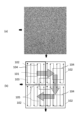
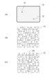
図1(a)に示すのは、樹脂成形品の表面に一様なマット感を付与するため、微細なドット形状(凹部)を重ねて配置した金型成形面の外観(平面形状)を示す写真である。複合方式でレーザ光を走査するレーザ加工機を使用して、成形面には肉眼では視認できないほど微細な径(約40μm)のドット形状(凹部)が形成されている。 Figure 1 (a) shows a photograph of the appearance (planar shape) of the molding surface of a mold on which minute dot shapes (recesses) are arranged in layers to give the surface of a resin molded product a uniform matte finish. Using a laser processing machine that scans laser light in a composite manner, dot shapes (recesses) with a diameter (approximately 40 μm) that are too fine to be seen with the naked eye are formed on the molding surface.
図1(a)を観察すると、矢印で示した位置に線状のパターンが視認されることがわかる。この線状のパターンは、従来の走査方法によりレーザ光を走査した際のガルバノスキャンエリアどうしの境界に位置しているが、もともと意図して形成したものではない。金型の成形面に、視認可能な線状のパターンが存在すると、成形した樹脂成形品にも視認可能な線状のパターンが転写され、樹脂成形品の外観品質が低下してしまう。 When observing Figure 1 (a), it can be seen that a linear pattern is visible at the position indicated by the arrow. This linear pattern is located at the boundary between galvano scan areas when laser light is scanned using a conventional scanning method, but it was not originally formed intentionally. If a visible linear pattern exists on the molding surface of the mold, the visible linear pattern will also be transferred to the molded resin molded product, reducing the appearance quality of the resin molded product.
図1(b)に示すのは、複合方式により金型成形面をレーザ光で加工する際の従来の走査手順を説明するための模式図である。図中の太い矢印101は、ガルバノミラーを備えた照射ヘッドをプロッタ方式で移動させる移動経路を示し、照射ヘッドは各矢印の始点位置または終点位置にてガルバノミラーを用いてガルバノ方式でレーザ光をスキャンする。矢印103は、ガルバノ方式によるレーザ光の走査経路であるが、図示の便宜上、走査経路のピッチを粗く示している。図1(b)の例では、4つのガルバノスキャンエリア102が隣接しており、各スキャンエリア内では、ミラーを駆動して走査経路である矢印103に沿ってレーザビームを走査している。
Figure 1(b) shows a schematic diagram for explaining a conventional scanning procedure when processing a mold molding surface with laser light by a composite method. The
図2(a)は、図1(a)に示した金型を用いて成形した樹脂成形品の表面形状を説明するための模式的な平面図であり、図2(b)は、図2(a)に示す一点鎖線P-P’に沿って樹脂成形品を切断した模式的な断面図である。尚、図示の便宜のため、図2(a)および図2(b)では、金型のドット形状(凹部)が転写された樹脂成形品の凸部を模式的に拡大して示しているが、実際には図示したよりも多数の凸部が微細なピッチで形成されている。 Figure 2(a) is a schematic plan view illustrating the surface shape of a resin molded product molded using the mold shown in Figure 1(a), and Figure 2(b) is a schematic cross-sectional view of the resin molded product cut along the dashed line P-P' shown in Figure 2(a). For ease of illustration, Figures 2(a) and 2(b) show enlarged schematic views of the convex portions of the resin molded product to which the dot shapes (concave portions) of the mold have been transferred, but in reality, many more convex portions are formed at a finer pitch than shown.
図1(b)と図2(a)を対比させると判るように、ガルバノスキャンエリア102の内部領域104では、隣接する凸部同士の重なり方は規則的(一定)である。しかし、ガルバノスキャンエリア102どうしの境界付近の領域105では、隣接する凸部同士の配列(重なり方)が、内部領域104における規則的な重なり方とは異なっている。この重なり方のパターンの変化は、複合方式でレーザ光を走査した際の照射順に依存して生じるものである。金型表面において先にレーザ光が照射されて形成された凹部の一部形状が、後からその近傍に照射されたレーザ光の影響を受けて変形する。これにより、図2(b)に示すように、内部領域104と境界付近の領域105において、樹脂成形物の凸部の形状が微細に異なったものになる場合がある。
1(b) and 2(a), the overlapping of adjacent convex portions is regular (constant) in the
このように、複合方式でレーザ光を走査して金型成形面を加工すると、ガルバノスキャンエリア102どうしの境界付近の領域105において、内部領域104と比べてドット形状(凹部)の重なり方や微細な形状に差異が生じる場合が有る。そうした成形面を有する金型を用いて製作した樹脂成形品では、ガルバノスキャンエリア102どうしの境界部に対応する位置において、転写されたドット(凸部)の重なり方や微細なドット形状に差異が生じることになる。一般に物体表面の反射特性は、その微細凹凸形状に依存して変化するが、樹脂成形品のその部分(ガルバノスキャンエリアの境界部)の反射特性が周囲と異なると、視覚的に目立ってしまい、樹脂成形品の外観品位が低下することがあった。
In this way, when the mold molding surface is processed by scanning laser light using a composite method, differences may occur in the overlap and fine shape of the dot shapes (concave portions) in the
そこで、複合方式でレーザ光を走査して広い面積にわたり金型成形面を加工する際に、成形品表面の反射特性に影響を及ぼすような形状パターンがガルバノスキャンエリアの境界部付近に形成されるのを抑制できる技術が求められていた。 Therefore, there was a need for technology that could prevent geometric patterns that would affect the reflection characteristics of the molded product surface from being formed near the boundaries of the galvano scan area when processing the mold molding surface over a wide area by scanning laser light using a combined method.
本発明の第1の態様は、レーザ光の光路を光学的に変更させて照射位置を変更可能なヘッドと、被照射物と前記ヘッドの相対位置を変更可能な移動部と、を備えた加工装置を用いる加工方法であって、前記被照射物と前記ヘッドが第1の相対位置にあるとき、前記ヘッドが前記被照射物の第1の領域内の複数の加工位置に対して、前記複数の加工位置の配列ピッチよりも大きなスポット径のレーザ光を順次照射して、前記加工位置のそれぞれに凹部を形成する第1照射工程と、前記被照射物と前記ヘッドが第2の相対位置にあるとき、前記ヘッドが前記被照射物の第2の領域内の複数の加工位置に対して、前記複数の加工位置の配列ピッチよりも大きなスポット径のレーザ光を順次照射して、前記加工位置のそれぞれに凹部を形成する第2照射工程と、を有し、前記第1の領域と前記第2の領域は隣接し、前記第1の領域と前記第2の領域の境界部には、前記第1照射工程で形成された凹部と前記第2照射工程で形成された凹部とが重なり合うことで形成される境界部領域が設けられ、前記ヘッドは、前記第1の領域内の複数の加工位置および前記第2の領域内の複数の加工位置に対して、前記境界部領域に存する前記凹部どうしの重なり方が、前記第1の領域内における前記凹部どうしの重なり方、および前記第2の領域内における前記凹部どうしの重なり方と、実質的に同じになるように前記第1照射工程と前記第2照射工程とが複数回繰り返して行われる照射順で前記被照射物の前記境界部領域の加工位置にレーザ光を照射する、ことを特徴とする加工方法である。 A first aspect of the present invention is a processing method using a processing device equipped with a head capable of optically changing an optical path of a laser beam to change an irradiation position, and a moving unit capable of changing a relative position between an irradiated object and the head, the method including a first irradiation step in which, when the irradiated object and the head are in a first relative position, the head sequentially irradiates a plurality of processing positions in a first region of the irradiated object with laser beams having a spot diameter larger than an arrangement pitch of the plurality of processing positions to form recesses at each of the processing positions, and a second irradiation step in which, when the irradiated object and the head are in a second relative position, the head sequentially irradiates a plurality of processing positions in a second region of the irradiated object with laser beams having a spot diameter larger than the arrangement pitch of the plurality of processing positions to form recesses at each of the processing positions. and a second irradiation step, wherein the first region and the second region are adjacent to each other, and a boundary region between the first region and the second region is provided where a recess formed in the first irradiation step and a recess formed in the second irradiation step overlap each other, and the head irradiates the laser light to the processing positions of the boundary region of the irradiated object in an irradiation order in which the first irradiation step and the second irradiation step are repeated a plurality of times so that, for a plurality of processing positions in the first region and a plurality of processing positions in the second region, a manner in which the recesses present in the boundary region overlap each other is substantially the same as a manner in which the recesses in the first region and the second region overlap each other .
また、本発明の第2の態様は、レーザ光の光路を光学的に変更させて照射位置を変更可能なヘッドと、被照射物と前記ヘッドの相対位置を変更可能な移動部と、を備え、前記被照射物と前記ヘッドが第1の相対位置にあるとき、前記ヘッドが前記被照射物の第1の領域内の複数の加工位置に対して、前記複数の加工位置の配列ピッチよりも大きなスポット径のレーザ光を順次照射して、前記加工位置のそれぞれに凹部を形成し、前記被照射物と前記ヘッドが第2の相対位置にあるとき、前記ヘッドが前記被照射物の第2の領域内の複数の加工位置に対して、前記複数の加工位置の配列ピッチよりも大きなスポット径のレーザ光を順次照射して、前記加工位置のそれぞれに凹部を形成し、前記第1の領域と前記第2の領域は隣接しており、前記第1の領域と前記第2の領域の境界部には、前記第1の領域内への照射で形成された凹部と前記第2の領域内への照射で形成された凹部とが重なり合うことで形成される境界部領域が設けられ、前記ヘッドは、前記第1の領域内の複数の加工位置および前記第2の領域内の複数の加工位置に対して、前記第1の領域と前記第2の領域の前記境界部領域に存する前記凹部どうしの重なり方が、前記第1の領域内における前記凹部どうしの重なり方、および前記第2の領域内における前記凹部どうしの重なり方と、実質的に同じになるように前記第1の領域内への照射と前記第2の領域内への照射とが複数回繰り返して行われる照射順で前記被照射物の前記境界部領域の加工位置にレーザ光を照射する、ことを特徴とする加工装置である。 A second aspect of the present invention is a laser irradiation method comprising: a head capable of optically changing an optical path of a laser beam to change an irradiation position; and a moving unit capable of changing a relative position between an irradiated object and the head; when the irradiated object and the head are in a first relative position, the head sequentially irradiates a plurality of processing positions in a first region of the irradiated object with laser beams having a spot diameter larger than an arrangement pitch of the plurality of processing positions to form recesses at each of the processing positions; when the irradiated object and the head are in a second relative position, the head sequentially irradiates a plurality of processing positions in a second region of the irradiated object with laser beams having a spot diameter larger than an arrangement pitch of the plurality of processing positions to form recesses at each of the processing positions; the first region and the second region are adjacent to each other; The processing device is characterized in that a boundary region between the first region and the second region is provided by overlapping a recess formed by irradiation into the first region and a recess formed by irradiation into the second region, and the head irradiates the laser light to the processing positions of the boundary region of the irradiated object in an irradiation order in which irradiation into the first region and irradiation into the second region are repeated multiple times so that the overlapping manner of the recesses in the boundary region between the first region and the second region is substantially the same as the overlapping manner of the recesses in the first region and the overlapping manner of the recesses in the second region for multiple processing positions in the first region and multiple processing positions in the second region.
本発明によれば、複合方式でレーザ光を走査して広い面積にわたり金型成形面を加工する際に、成形品表面の反射特性に影響を及ぼすような形状パターンがガルバノスキャンエリアの境界部付近に形成されるのを抑制することができる。 According to the present invention, when a laser beam is scanned using a combined method to process a mold molding surface over a wide area, it is possible to prevent the formation of geometric patterns near the boundaries of the galvano scan area that may affect the reflection characteristics of the molded product surface.
図面を参照して、本発明の実施形態である樹脂成形品の製造方法、樹脂成形品を成形する金型の製造方法、等について説明する。
尚、以下の実施形態及び実施例の説明において参照する図面では、特に但し書きがない限り、同一の参照番号を付して示す要素は、同一または類似の機能を有するものとする。
DETAILED DESCRIPTION OF THE PREFERRED EMBODIMENTS A method for manufacturing a resin molded product, a method for manufacturing a die for molding a resin molded product, and the like according to embodiments of the present invention will be described with reference to the drawings.
In the drawings referred to in the following description of the embodiments and examples, elements denoted by the same reference numbers have the same or similar functions unless otherwise specified.
本発明は、例えば家電製品や電子機器の筐体、自動車などの移動体の外装部品や内装部品、カメラ用レンズの鏡筒など、高品位な外観が要求される樹脂成形品において好適に実施することができる。一例を挙げれば、図3に示すプリンタの外装部品において好適に実施することができる。 The present invention can be suitably implemented in resin molded products that require a high-quality appearance, such as the housings of home appliances and electronic devices, the exterior and interior parts of moving objects such as automobiles, and the lens barrels of camera lenses. As an example, the present invention can be suitably implemented in the exterior parts of a printer as shown in Figure 3.
図3は、原稿読取装置を備えた複合型プリンタ2の外観を示す斜視図であり、原稿カバー22や筐体20は、例えば黒色の樹脂で成形されている。これら各部の外観面21は、通常の使用状態においてユーザの目に触れやすい部分であり、光沢あるいはマット感など高品位な外観が求められる部分である。
Figure 3 is a perspective view showing the exterior of a
外観面21を構成する樹脂部品を製造する手順について、以下に説明する。
図4は、外観面21を構成する樹脂部品の製造プロセスを説明するためのフローチャートである。
まず、金型形状加工工程31において、金属等の母材を切削加工して、製造しようとする樹脂成形品の凹凸形状を反転させた金型を作成する。切削加工後、必要に応じて金型の成形面を鏡面加工するのが望ましい。
The procedure for manufacturing the resin part that constitutes the
FIG. 4 is a flow chart for explaining a manufacturing process of the resin part that constitutes the
First, in the die
次に、金型表面加工工程32において、金型の成形面の中で、外観面21を転写する領域に対してレーザ加工を行い、樹脂成形品の光沢を制御するための微細構造を形成する。本実施形態におけるレーザ加工方法については、後に詳しく述べるが、予め金型形状加工工程31において成形面を鏡面加工してからレーザ加工を行うことが望ましい。
そして、樹脂成形工程33において、加工済の金型に樹脂を充填することにより、表面光沢が制御された樹脂成形品を得る。
Next, in a mold
Then, in the
(金型表面加工)
次に、金型表面加工工程32におけるレーザ加工方法について詳細に説明する。
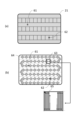
図5(a)および図5(b)は、金型表面加工工程32において金型表面を加工するのに用いるマシニングセンタを示す模式図である。図5(a)は、マシニングセンタの加工機本体であるレーザ加工機(レーザ加工装置)の外観斜視図および一部拡大図を示している。図5(b)は、マシニングセンタのブロック図を示している。
(Mold surface treatment)
Next, the laser processing method in the mold
Figures 5(a) and 5(b) are schematic diagrams showing a machining center used to process the surface of a mold in the mold
マシニングセンタ40は、制御装置42(制御部)と加工機本体41とを有する。制御装置42は、CPU及びメモリ等を有するコンピュータで構成され、加工データ43を用いて加工機本体41を制御する。加工データ43には、レーザ加工で使用する各種の指令(プログラム)が含まれている。プログラムは、コンピュータ読み取り可能な記録媒体であれば、いかなる記録媒体に記録されていてもよい。例えば、プログラムを供給するための記録媒体としては、ROM、ディスク、外部記憶装置等を用いてもよい。具体例を挙げて説明すると、記録媒体として、フレキシブルディスク、光ディスク、光磁気ディスク、磁気テープ、USBメモリ等の不揮発性メモリ、SSD等を用いることができる。
The
制御装置42は、複数の機能ブロック(モジュール)を含んでいるが、これらの機能ブロックは、例えば記憶装置や非一時的な記録媒体に記憶された制御プログラムを、CPUが読み出して実行することにより構成され得る。あるいは、制御装置42が備えるASIC等のハードウェアにより、機能ブロックの一部または全部を構成してもよい。
The
制御装置42が備える不図示の表示装置および入力装置は、ユーザインターフェースとして用いられる。表示装置には、例えば液晶ディスプレイや有機ELディスプレイなどの表示デバイスが用いられ、入力装置には、例えばキーボード、ジョグダイアル、マウス、ポインティングデバイス、音声入力機などの入力デバイスが用いられる。
The display device and input device (not shown) provided in the
加工機本体41としてのレーザ加工機410は、直線軸X、直線軸Y、直線軸Zの3軸で駆動可能に構成されている。レーザ加工機には、さらに多くの軸で構成されているものもあるが、その様なレーザ加工機を使用しても構わない。これらの駆動軸は、被照射物とヘッドの相対位置を変更可能であればよく、被照射物を固定してヘッドを移動させてもよいし、ヘッドを固定して被照射物を移動させてもよいし、ヘッドと被照射物の両方を移動させてもよい。
The
レーザビームを照射するためのヘッド411は、レーザ発振器412、レーザビームの整形や集束を行うレンズ群413、レーザビーム418の照射方向を制御するX方向ガルバノミラー414、Y方向ガルバノミラー416を備えている。X方向ガルバノミラー414はX方向アクチュエーター415により、Y方向ガルバノミラー416はY方向アクチュエーター417により、それぞれ駆動される。ヘッド411は、レーザ光の光路を光学的に変更させて照射位置を変更可能である。
The
制御装置42は、移動部としてのX軸、Y軸、Z軸を駆動制御して、ヘッド411をプロッタ方式で移動させることができる。また、制御装置42は、X方向アクチュエーター415およびY方向アクチュエーター417を駆動制御して、ガルバノミラーを用いてガルバノ方式でレーザ光をスキャンすることができる。すなわち、レーザ加工機410は、複合方式でレーザビームを走査して、金型成形面の広い面積を加工することができる。金型表面加工工程32において、レーザ加工機410は複合方式でレーザビームを走査して、金型の成形面に樹脂成形品の表面光沢を制御するための微細構造を形成してゆく。
The
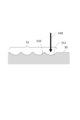
図6は、レーザによる金型表面加工を説明するための模式的な断面図であり、金型の表面50にレーザビーム418が照射され、複数のドット形状(凹部51)が順次形成されてゆく様子を示している。先に加工された凹部510は、他の凹部511を加工するために後から照射されたレーザ光の影響を受けて変形し、凹部510に凹部511が重なった形状となる。
Figure 6 is a schematic cross-sectional view for explaining the laser processing of the mold surface, showing how the
言い換えれば、複数の加工位置に対して、加工位置の配列ピッチよりも大きなスポット径のレーザ光を順次照射して、加工位置のそれぞれに凹部を形成してゆく。スポット径が加工位置の配列ピッチよりも大きなため、隣接する凹部についてみれば、先に形成された凹部の一部は、後から照射されたレーザ光に照射され、後から形成された別の凹部が重ねられたように変形するのである。 In other words, multiple processing positions are sequentially irradiated with laser light having a spot diameter larger than the arrangement pitch of the processing positions, forming recesses at each of the processing positions. Because the spot diameter is larger than the arrangement pitch of the processing positions, when we look at adjacent recesses, a part of the previously formed recess is irradiated with the later irradiated laser light, and is deformed as if another recess formed later was superimposed on top of it.
従来の複合方式による走査方法のように、隣接する凹部の重なり順がガルバノスキャンエリア境界部においてのみ異なると、ガルバノスキャンエリアの境界に視認可能な微細形状パターン(線状パターン)が形成されてしまう。
すなわち、従来の複合方式によるレーザ走査方法により金型の表面加工を行い、その金型を用いて複合型プリンタの原稿カバーを作成すると、図7(a)に示すように、樹脂部品の外観面21には、視認可能な線状パターンが形成されてしまう。図7(a)では、ガルバノスキャンエリア境界部に対応する位置に、視認可能な線状パターンがラダー状に形成されてしまった状況を模式的に示している。尚、領域61は、ガルバノスキャンエリア内に対応する位置の小領域を示し、領域62は、ガルバノスキャンエリア境界部に対応する位置の小領域を示している。
If the overlapping order of adjacent recesses differs only at the boundary between galvano scan areas, as in the conventional composite scanning method, a visible fine shape pattern (linear pattern) is formed at the boundary between the galvano scan areas.
That is, when a mold is surface-processed by a conventional composite laser scanning method and a document cover for a composite printer is produced using the mold, a visible linear pattern is formed on the
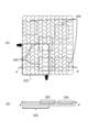
図7(b)は、従来の加工方法により金型の表面加工を行なった際の、レーザビームの走査手順を示す模式図である。また、図8(a)は、当該金型を用いて成形した樹脂成形品の領域61における凸部の形成状況を示す模式図であり、図8(b)は、領域62における凸部の形成状況を示す模式図である。
Figure 7(b) is a schematic diagram showing the scanning procedure of a laser beam when processing the surface of a mold using a conventional processing method. Also, Figure 8(a) is a schematic diagram showing the formation of a convex portion in
図7(b)において、太い矢印64は、ガルバノミラーを備えたヘッドをプロッタ方式で移動させた移動経路を示し、照射ヘッドは各矢印の始点位置または終点位置にてガルバノミラーを用いてガルバノ方式でレーザ光をスキャンする。図の下部に、ガルバノスキャンエリアを拡大して示すが、細い矢印65は、ガルバノ方式によるレーザ光の走査経路を示している。尚、図7(b)は、樹脂成形物ではなく金型を示しているが、樹脂成形物の領域61、領域62に対応する位置に、便宜的に61、62の参照番号を図示している。
In FIG. 7(b), the
樹脂成形品(樹脂成形物)の外観面21には、マットな質感を持たせるために、多数の微細な凸部が形成されているが、本来は一様なマット感であるべきところ、図7(a)を参照して説明したように、視認可能な線状パターンが形成されている。すなわち、ガルバノスキャンエリア内部の領域61では、図8(a)に示すように、微細な凸部の重なり方は一様に規則的である。この領域に対応する金型の表面加工では、常に左側よりも右側の加工順が後であり、樹脂成形品では左の凸部に右の凸部が覆い被さって見えるような規則的な繰り返しパターンとなっている。しかし、ガルバノスキャンエリアの境界部付近の領域62では、図8(b)に示すように、大半の列では領域61と同様に右側の加工順が後となっているが、ガルバノスキャンエリア境界63に位置する列でのみ異なる加工順となっている。すなわち、ガルバノスキャンエリアの境界部付近のみ、パターンの規則性が崩れている。上述したように、こうしたパターンの変化により反射特性の変化が生じ、結果として樹脂成形品の外観面において、ライン状のパターンが視認されてしまうのである。
A large number of fine protrusions are formed on the
本実施形態では、ガルバノスキャンエリアの境界部に対応する位置において、樹脂成形品に反射特性の差異が生じるのを抑制するために、凸部の重なり順の態様が境界部と他の部分とで同様になるように、金型表面加工のレーザ光の照射手順を設定する。
以下では、まず実施形態に係る樹脂成形品の形状について図面を参照して説明し、その後に金型表面加工におけるレーザ光の照射手順について説明する。
In this embodiment, in order to suppress differences in the reflection characteristics of the resin molded product at positions corresponding to the boundaries of the galvano scan area, the procedure for irradiating the laser light for processing the mold surface is set so that the overlap order of the convex portions is similar at the boundaries and other parts.
In the following, first, the shape of the resin molded product according to the embodiment will be described with reference to the drawings, and then the procedure for irradiating the laser light in processing the surface of the mold will be described.
[実施形態1]
図9(a)は、実施形態1に係る樹脂成形品の外観面21の全体を示す模式的な平面図である。図中の領域71は、当該樹脂成形品用の金型の成形面に表面加工をした際の、ガルバノスキャンエリア内に対応する位置の小領域を示している。また、領域72は、ガルバノスキャンエリア境界部に対応する位置の小領域を示している。また、図9(b)と図9(c)は、それぞれ領域71と領域72の拡大図である。
[Embodiment 1]
Fig. 9(a) is a schematic plan view showing the entire
図示のように、実施形態1では、樹脂成型品の全域において、凸部の重なり順に単純な規則性は見られず、周囲と比べて重なり順が特異的に異なるような部分は、領域71および領域72の拡大図をもってしても認識することができない。すなわち、領域72のガルバノスキャンエリア境界63の付近に、周囲と比べて凸部が特異的な重なり方をしている部分(周囲と反射率が異なる部分)は存在しない。
As shown in the figure, in
従って、実施形態1に係る樹脂成形品では、ガルバノスキャンエリア境界に対応する位置において意図しないパターンが視認されることはなく、図9(a)に示すように、一様な光沢あるいはマット感を呈する外観面を備えることができる。
Therefore, in the resin molded product of
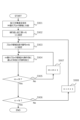
次に、実施形態1に係る金型表面加工方法を説明する。図10は、図9(b)と図9(c)に示した不規則な重なり順の凸部を形成するための金型を製造する際の、表面加工処理のフローチャートである。 Next, the mold surface processing method according to the first embodiment will be described. Figure 10 is a flowchart of the surface processing process when manufacturing a mold for forming the irregular overlapping order of the convex portions shown in Figures 9(b) and 9(c).
まず、ステップS901において、表面加工処理を行う金型成形面の全体を、ガルバノスキャンエリアと同サイズのブロック領域に分割する。以後、分割して得られるブロック領域の個数をMとする。尚、ここでいう分割とは仮想的に区分するという意味であり、金型を物理的に分断するという意味ではない。 First, in step S901, the entire molding surface of the mold to be surface-treated is divided into block areas of the same size as the galvano scan area. Hereinafter, the number of block areas obtained by division is designated as M. Note that division here means to virtually divide the mold, and does not mean to physically separate the mold.
次に、ステップS902において、繰り返し加工数nを1に設定する。本処理では各ブロック領域への加工をN回に分割して行うため、その加工数を管理する変数をnと設定している。そして、ステップS903において、ブロック領域を表すブロック番号mを1に設定する。 Next, in step S902, the number of repeated processes n is set to 1. In this process, the processing of each block area is divided into N processes, so the variable that manages the number of processes is set to n. Then, in step S903, the block number m that represents the block area is set to 1.
次に、ステップS904において、m番のブロック領域に加工するKm個の凹部のうち、未加工の凹部からKm/N個を無作為に選んで(例えばランダム関数や疑似ランダム関数を用いた情報処理で凹部をランダムに選んで)、加工する。具体的には、m番のブロック領域がガルバノスキャンエリアに含まれる位置にヘッドを移動した後、ミラー制御によりレーザ光を走査して、選択した凹部の加工位置へ順次レーザ光を照射する。 Next, in step S904, of the Km recesses to be machined in the mth block region, Km/N recesses are randomly selected from the unmachined recesses (for example, by randomly selecting recesses by information processing using a random function or a pseudorandom function) and machined. Specifically, after the head is moved to a position where the mth block region is included in the galvano scan area, the laser light is scanned by mirror control, and the laser light is sequentially irradiated to the machining positions of the selected recesses.
ステップS905において、ブロック番号mがM、すなわち最終領域であるか否かを判定する。最終領域Mでなかった場合(ステップS905:No)には、ステップS907に進み、ブロック番号mを1進めてステップS904に戻る。最終領域Mであった場合(ステップS905:Yes)には、ステップS906に進む。 In step S905, it is determined whether block number m is M, i.e., whether it is the final region. If it is not the final region M (step S905: No), proceed to step S907, increment block number m by 1, and return to step S904. If it is the final region M (step S905: Yes), proceed to step S906.
ステップS906では、繰り返し加工数nがNであるか否かを判定する。繰り返し加工数nがNでなかった場合(ステップS906:No)には、ステップS908に進み、繰り返し加工数nを1進めてステップS903に戻る。繰り返し加工数nがNであった場合(ステップS906:Yes)には、全ての凹部を加工したと判断し、処理を終了する。 In step S906, it is determined whether the number of repeated processes n is N. If the number of repeated processes n is not N (step S906: No), the process proceeds to step S908, increments the number of repeated processes n by 1, and returns to step S903. If the number of repeated processes n is N (step S906: Yes), it is determined that all recesses have been processed, and the process ends.
本実施形態では、このような手順で金型表面処理を行うため、ガルバノスキャンエリア内部とガルバノスキャンエリア境界部のいずれにおいても、凹部の重なり順は規則性を持つことがない。本実施形態では、金型に対してヘッドが第1の相対位置にある時に第1の領域に凹部を形成し、金型に対してヘッドが第2の相対位置にある時に第2の領域に凹部を形成する。その際、隣接した第1の領域と第2の領域の境界部に存する凹部どうしの重なり方が、第1の領域内における凹部どうしの重なり方、および第2の領域内における凹部どうしの重なり方と、実質的に同じになるような照射順で金型にレーザ光を照射する。第1の領域内の複数の加工位置および第2の領域内の複数の加工位置に対して、照射順がランダムになるようにレーザ光を照射する。金型成形面のガルバノスキャンエリア境界の付近に、周囲と比べて凹部が特異的な重なり方をしている部分は存在しない。このため、金型の成形面形状を転写したときに、成形物の外面には、周囲に比べて反射率が異なる部分(周囲と比べて凸部が特異的な重なり方をしている部分)が形成されることはない。すなわち、本実施形態によれば、所望の光沢度あるいはマット感が付与された品位の高い外観面を備えた成形品を製造することが可能である。 In this embodiment, the mold surface treatment is performed in this manner, so that the overlap order of the recesses has no regularity either inside the galvano scan area or at the boundary of the galvano scan area. In this embodiment, a recess is formed in the first region when the head is in a first relative position with respect to the mold, and a recess is formed in the second region when the head is in a second relative position with respect to the mold. At that time, the mold is irradiated with laser light in an irradiation order such that the overlap of the recesses at the boundary between the adjacent first and second regions is substantially the same as the overlap of the recesses in the first region and the overlap of the recesses in the second region. Laser light is irradiated to a plurality of processing positions in the first region and a plurality of processing positions in the second region so that the irradiation order is random. There is no portion near the boundary of the galvano scan area on the mold molding surface where the recesses overlap in a unique manner compared to the surroundings. Therefore, when the shape of the molding surface of the mold is transferred, no part with a different reflectance compared to the surrounding area (part with convex parts overlapping in a unique way compared to the surrounding area) is formed on the outer surface of the molded product. In other words, according to this embodiment, it is possible to manufacture a molded product with a high-quality exterior surface that is given the desired gloss or matte finish.
[実施形態2]
実施形態1では、金型表面処理を行う際に、表面全域において凹部の重なり順の規則性を排除することで、ガルバノスキャンエリア境界に周囲と比べて特異な重なりパターンが発生するのを抑制していた。
これに対して、実施形態2は、樹脂成型品の外観面における凸部の重なり順が単純なパターンの繰り返しとなるようにし、なおかつガルバノスキャンエリア境界部に対応する位置に特異な重なりパターンが発生しないようにする。
[Embodiment 2]
In the first embodiment, when performing surface treatment on a mold, the regularity of the overlapping order of recesses is eliminated across the entire surface, thereby suppressing the occurrence of an overlapping pattern that is unique to the boundary of the galvano scan area compared to the surrounding area.
In contrast, in the second embodiment, the overlapping order of the convex portions on the exterior surface of the resin molded product is made to be a simple repetition of a pattern, and no peculiar overlapping pattern is generated at positions corresponding to the boundaries of the galvano scan areas.
図11(a)は、実施形態2に係る樹脂成形品の外観面21の全体を示す模式的な平面図である。図中の領域81は、当該樹脂成形品用の金型成形面の表面加工をした際の、ガルバノスキャンエリア内に対応する位置の小領域を示している。また、領域82は、ガルバノスキャンエリア境界部に対応する位置の小領域を示している。また、図11(b)と図11(c)は、それぞれ領域81と領域82の拡大図である。
Figure 11(a) is a schematic plan view showing the entire
図示のように、実施形態2では、領域81および領域82の全域において、凸部の重なり順は単純な規則性を有している。すなわち、領域82のガルバノスキャンエリア境界63の付近に、周囲と比べて凸部が特異的な重なり方をしている部分(周囲と反射率が異なる部分)は存在しない。
As shown in the figure, in the second embodiment, the overlap order of the convex portions has a simple regularity throughout the
従って、実施形態2に係る樹脂成形品では、ガルバノスキャンエリア境界に対応する位置において意図しないパターンが視認されることはなく、図11(a)に示すように、一様な光沢あるいはマット感を呈する外観面を備えることができる。
Therefore, in the resin molded product of
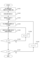
次に、実施形態2に係る金型表面加工方法を説明する。図12は、図11(b)と図11(c)に示した規則的な重なり順の凸部を形成するための金型を製造する際の、表面加工処理のフローチャートである。
ステップS1001は、実施形態1におけるステップS901と同様の処理である。
Next, a description will be given of a mold surface processing method according to
Step S1001 is the same process as step S901 in the first embodiment.
次に、ステップS1002において、各凹部に何回目の繰り返し加工において加工を行うかを表す番号iを割り当てる。番号の割り当ては、同一の番号が割り当てられた凹部がブロック領域の境界線上で重ならないように、かつ、加工面全体が単一のパターンの繰り返しとなるように行う。例えば、図13(a)に示すパターン111を、図13(b)に示すように加工面にタイリングして番号を割り当てればよい。
ステップS1003、S1004は、それぞれ実施形態1におけるステップS902、S903と同様の処理である。
Next, in step S1002, a number i is assigned to each recess, which indicates the number of repeated machining operations in which the recess is to be machined. The numbers are assigned so that recesses assigned the same number do not overlap on the boundary line of the block area, and so that the entire machining surface is a repetition of a single pattern. For example, the
Steps S1003 and S1004 are similar to steps S902 and S903 in the first embodiment, respectively.
次に、ステップS1005においては、m番のブロック領域に加工する凹部のうち、ステップS1002において割り当てられた番号iがnである凹部を加工する。
そして、ステップS1006において、ブロック番号mがM、すなわち最終領域であるか否かを判定する。最終領域Mでなかった場合(ステップS1006:No)はステップS1008に進み、ブロック番号mを1進めてステップS1005に戻る。最終領域Mであった場合(ステップS1006:Yes)には、ステップS1007に進む。
Next, in step S1005, among the recesses to be machined in the mth block region, the recesses whose number i assigned in step S1002 is n are machined.
Then, in step S1006, it is determined whether or not the block number m is M, i.e., the final region. If it is not the final region M (step S1006: No), the process proceeds to step S1008, where the block number m is incremented by 1, and the process returns to step S1005. If it is the final region M (step S1006: Yes), the process proceeds to step S1007.
ステップS1007では、繰り返し加工数nがNであるか否かを判定する。Nでなかった場合(ステップS1007:No)は、ステップS1009に進み繰り返し加工数nを1進めてステップS1004に戻る。Nであった場合(ステップS1007:Yes)には、全ての凹部を加工したと判断し、処理を終了する。 In step S1007, it is determined whether the number of repeated processes n is N. If it is not N (step S1007: No), the process proceeds to step S1009, increments the number of repeated processes n by 1, and returns to step S1004. If it is N (step S1007: Yes), it is determined that all recesses have been processed, and the process ends.
本実施形態では、このような手順で金型表面処理を行うため、ガルバノスキャンエリア内部とガルバノスキャンエリア境界部のいずれにおいても、凹部の重なり順は同一の規則性を持つことになる。本実施形態では、金型に対してヘッドが第1の相対位置にある時に第1の領域に凹部を形成し、金型に対してヘッドが第2の相対位置にある時に第2の領域に凹部を形成する。その際、第1の領域と第2の領域の境界部に存する凹部どうしの重なり方が、第1の領域内における凹部どうしの重なり方、および第2の領域内における凹部どうしの重なり方と、実質的に同じになるような照射順で金型にレーザ光を照射する。すなわち、第1の領域内の複数の加工位置および第2の領域内の複数の加工位置に対して、同じ規則で決められた照射順にしたがってレーザ光を照射する。金型成形面のガルバノスキャンエリア境界の付近に、周囲と比べて凹部が特異的な重なり方をしている部分は存在しない。このため、金型の成形面形状を転写したときに、成形物の外面には、周囲に比べて反射率が異なる部分(周囲と比べて凸部が特異的な重なり方をしている部分)が形成されることはない。すなわち、本実施形態によれば、所望の光沢度あるいはマット感が付与された品位の高い外観面を備えた成形品を製造することが可能である。 In this embodiment, the mold surface treatment is performed in this manner, so that the overlap order of the recesses has the same regularity both inside the galvano scan area and at the boundary of the galvano scan area. In this embodiment, when the head is in a first relative position with respect to the mold, a recess is formed in the first region, and when the head is in a second relative position with respect to the mold, a recess is formed in the second region. At that time, the mold is irradiated with laser light in an irradiation order such that the overlap of the recesses at the boundary between the first region and the second region is substantially the same as the overlap of the recesses in the first region and the overlap of the recesses in the second region. That is, the laser light is irradiated to a plurality of processing positions in the first region and a plurality of processing positions in the second region according to an irradiation order determined by the same rule. There is no portion near the boundary of the galvano scan area on the mold molding surface where the recesses overlap in a unique manner compared to the surroundings. Therefore, when the shape of the molding surface of the mold is transferred, no part with a different reflectance compared to the surrounding area (part with convex parts overlapping in a unique way compared to the surrounding area) is formed on the outer surface of the molded product. In other words, according to this embodiment, it is possible to manufacture a molded product with a high-quality exterior surface that is given the desired gloss or matte finish.
以下、具体的な実施例について説明する。 Specific examples are described below.
[実施例1]
実施形態1に係る具体的な実施例1について、図14(a)、図14(b)を参照して、説明する。図14(a)は、実施例1に係る樹脂成形品の全体平面図、図14(b)は、図14(a)に示した領域121を拡大した図である。
[Example 1]
A specific example 1 according to the
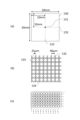
本実施例では、厚さ1.6mm、縦・横20mmの板状の樹脂成形品の外観面全面に凸部122を形成した。凸部122は、直径が40μm、高さが10μmであり、各凸部の間隔は25μmとなるように凸部を形成した。このように微細な凸部を全面に形成することで、樹脂成形品120の表面はマットな質感を持つ低光沢面となった。
In this example,
樹脂成形品を製造するための金型は、材料にステンレスを使用し、図示しない切削加工機を用いて荒加工および鏡面加工を施した。その後、図5に示すマシニングセンタにて、樹脂成形品に凸部122を形成するための凹部を、図10を参照して説明した実施形態1の手順に従って金型成形面に形成した。その際には、繰り返し加工回数Nを4として加工を行った。尚、本実施例におけるガルバノスキャンエリアの大きさは、10mm×10mmとし、ブロック領域も同様に設定した。よって、金型の加工領域は2×2個のブロック領域に分割した。その後、当該金型を用いて射出成形を行い、樹脂成形品120を得た。尚、樹脂材料はHIPSで黒色を使用した。
The mold for manufacturing the resin molded product was made of stainless steel, and was rough-machined and mirror-finished using a cutting machine (not shown). After that, a recess for forming a
得られた樹脂成形品の外観面について、標準的な視力の人に目視により観察してもらい、ガルバノスキャンエリアの境界部分123における境界線の有無について評価した。結果、境界線はほとんど視認できないことを確認した。特に、従来手法によって成形面を加工した金型を用いて成形した樹脂成形品と比較すると、境界線の視認性の違いは歴然であり、本実施例の方が境界線の視認性が大幅に抑制されていることを確認できた。
The external appearance of the obtained resin molded product was visually observed by a person with normal eyesight, and the presence or absence of a boundary line at the
[実施例2]
実施形態2に係る具体的な実施例2について、図15(a)、図15(b)および図15(c)を参照して説明する。図15(a)は、実施例2に係る樹脂成形品の全体平面図、図15(b)は、図15(a)に示した領域131を拡大した図である。また、図15(c)は、実施例2に係る樹脂成形品を製造するための金型を作成する際に、表面加工時に加工面にタイリングして番号を割り当てる状況を示す図である。
[Example 2]
A specific example 2 according to the second embodiment will be described with reference to Fig. 15(a), Fig. 15(b) and Fig. 15(c). Fig. 15(a) is an overall plan view of a resin molded product according to the second embodiment, and Fig. 15(b) is an enlarged view of an
本実施例においても、実施例1と同様の外形寸法の板状の樹脂成形品130を成形した。樹脂成形品130の外観を図15(a)に示す。図15(b)から明らかなように、本実施例では、光沢あるいはマット感を制御するための凸部の重なり方が、実施例1とは異なっている。
In this embodiment, a plate-shaped resin molded
樹脂成形品を製造するための金型は、材料にステンレスを使用し、図示しない切削加工機を用いて荒加工および鏡面加工を施した。その後、図5に示すマシニングセンタにて、樹脂成形品に凸部122を形成するための凹部を、図10を参照して説明した実施形態1の手順に従って金型成形面に形成した。その際、繰り返し加工回数Nを4とし、図15(c)に示すように番号iを割り当てて加工を行った。なお、金型の加工領域は実施例1と同じく4×4個のブロック領域に分割した。その後、当該金型を用いて射出成形を行い、樹脂成形品120を得た。尚、樹脂材料はHIPSで黒色を使用した。
The mold for manufacturing the resin molded product was made of stainless steel, and was rough-machined and mirror-finished using a cutting machine (not shown). After that, a recess for forming a
得られた樹脂成形品の外観面について、標準的な視力の人に目視により観察してもらい、ガルバノスキャンエリアの境界部分133における境界線の有無について評価した。結果、境界線はほとんど視認できないことを確認した。特に、従来手法によって成形面を加工した金型を用いて成形した樹脂成形品と比較すると、境界線の視認性の違いは歴然であり、本実施例の方が境界線の視認性が大幅に抑制されていることを確認できた。
The external appearance of the obtained resin molded product was visually observed by a person with normal eyesight, and the presence or absence of a boundary line at the
[その他の実施例]
前記実施例においては、ブロック領域をレーザ加工機のガルバノスキャンエリアと同等の大きさに設定していたが、ブロック領域の大きさはガルバノスキャンエリア以下であればどのような大きさであっても構わない。ブロック領域をガルバノスキャンエリアよりも小さく設定した場合は、レーザ加工機側のガルバノスキャンエリアの設定をブロック領域に合わせるようにすれば良い。
[Other Examples]
In the above embodiment, the block area is set to a size equal to the galvano scan area of the laser processing machine, but the size of the block area may be any size as long as it is equal to or smaller than the galvano scan area. If the block area is set smaller than the galvano scan area, the setting of the galvano scan area on the laser processing machine can be adjusted to match the block area.
また、前記実施例においては、樹脂成形品の外観面全面に凸部を形成していたが、凸部は必ずしも全面に一様に配置しなくても良い。表面の光沢を制御するために、凸部の数や配置密度を調整する場合にも本発明は適用できる。尚、従来の方法でガルバノスキャンエリアの境界線が視認されるのは、凸部の面積占有率が約50%以上の場合である。 In addition, in the above embodiment, the convex portions are formed over the entire exterior surface of the resin molded product, but the convex portions do not necessarily have to be arranged uniformly over the entire surface. The present invention can also be applied to cases where the number of convex portions or their arrangement density is adjusted to control the surface gloss. Note that with the conventional method, the boundary line of the galvano scan area is visible when the area occupancy rate of the convex portions is approximately 50% or more.
また、前記実施例においては、凸部の高さを10μm、間隔を25μmとしたが、これに限らないことは言うまでもない。本発明の適用範囲としては、凸部の高さ・間隔(大きさに相当)に制限はないが、視認できない大きさであることが望ましい。 In addition, in the above embodiment, the height of the protrusions is 10 μm and the interval is 25 μm, but it goes without saying that this is not limited to this. There is no limit to the height and interval (equivalent to size) of the protrusions within the scope of application of the present invention, but it is desirable that they are of a size that cannot be visually recognized.
更には、凸部の高さは樹脂成形品の外観面の位置毎に異なっていても良い。例えば凸部の高さを位置毎に変化させることで表面をより粗すことができるため、よりマットな質感を得ることが出来る。このような樹脂成形品に対しても本発明は適用可能である。 Furthermore, the height of the convex parts may differ depending on the position on the exterior surface of the resin molded product. For example, by varying the height of the convex parts depending on the position, the surface can be made rougher, resulting in a more matte texture. The present invention can also be applied to such resin molded products.
[他の実施形態]
本発明は、以上説明した実施形態や実施例に限定されるものではなく、本発明の技術的思想内で多くの変形が可能である。
上述した金型の製造方法や、樹脂成形品の製造方法に係る制御方法を実行可能な制御プログラム、制御プログラムを格納したコンピュータで読み取り可能な記録媒体も、本発明の実施形態に含まれる。
[Other embodiments]
The present invention is not limited to the above-described embodiments and examples, and many modifications are possible within the technical concept of the present invention.
The embodiments of the present invention also include a control program capable of executing a control method relating to the above-described manufacturing method of a mold and a manufacturing method of a resin molded product, and a computer-readable recording medium storing the control program.
本発明は、実施形態の1以上の機能を実現するプログラムを、ネットワーク又は記憶媒体を介してシステム又は装置に供給し、そのシステム又は装置のコンピュータにおける1つ以上のプロセッサーがプログラムを読出し実行する処理でも実現可能である。また、1以上の機能を実現する回路(例えば、ASIC)によっても実現可能である。 The present invention can also be realized by supplying a program that realizes one or more of the functions of the embodiments to a system or device via a network or storage medium, and having one or more processors in the computer of the system or device read and execute the program. It can also be realized by a circuit (e.g., an ASIC) that realizes one or more of the functions.
2・・・複合型プリンタ/20・・・筐体/21・・・外観面/22・・・原稿カバー/40・・・マシニングセンタ/41・・・加工機本体/42・・・制御装置/43・・・加工データ/50・・・表面/51・・・凹部/63・・・ガルバノスキャンエリア境界/64・・・太い矢印(ガルバノミラーを備えたヘッドをプロッタ方式で移動させた移動経路)/65・・・細い矢印(ガルバノ方式によるレーザ光の走査経路)/410・・・レーザ加工機/418・・・レーザビーム 2... Multi-function printer / 20... Housing / 21... Exterior surface / 22... Document cover / 40... Machining center / 41... Machine body / 42... Control device / 43... Processing data / 50... Surface / 51... Recess / 63... Galvano scan area boundary / 64... Thick arrow (path of movement of head equipped with galvano mirror moved by plotter method) / 65... Thin arrow (path of laser light scanning by galvano method) / 410... Laser processing machine / 418... Laser beam
Claims (15)
被照射物と前記ヘッドの相対位置を変更可能な移動部と、を備えた加工装置を用いる加工方法であって、
前記被照射物と前記ヘッドが第1の相対位置にあるとき、前記ヘッドが前記被照射物の第1の領域内の複数の加工位置に対して、前記複数の加工位置の配列ピッチよりも大きなスポット径のレーザ光を順次照射して、前記加工位置のそれぞれに凹部を形成する第1照射工程と、
前記被照射物と前記ヘッドが第2の相対位置にあるとき、前記ヘッドが前記被照射物の第2の領域内の複数の加工位置に対して、前記複数の加工位置の配列ピッチよりも大きなスポット径のレーザ光を順次照射して、前記加工位置のそれぞれに凹部を形成する第2照射工程と、を有し、
前記第1の領域と前記第2の領域は隣接し、前記第1の領域と前記第2の領域の境界部には、前記第1照射工程で形成された凹部と前記第2照射工程で形成された凹部とが重なり合うことで形成される境界部領域が設けられ、
前記ヘッドは、前記第1の領域内の複数の加工位置および前記第2の領域内の複数の加工位置に対して、
前記境界部領域に存する前記凹部どうしの重なり方が、前記第1の領域内における前記凹部どうしの重なり方、および前記第2の領域内における前記凹部どうしの重なり方と、実質的に同じになるように前記第1照射工程と前記第2照射工程とが複数回繰り返して行われる照射順で前記被照射物の前記境界部領域の加工位置にレーザ光を照射する、
ことを特徴とする加工方法。 a head capable of optically changing the optical path of the laser light to change the irradiation position;
A processing method using a processing apparatus having a moving unit capable of changing a relative position between an object to be irradiated and the head,
a first irradiation step in which, when the object to be irradiated and the head are in a first relative position, the head sequentially irradiates a plurality of processing positions in a first region of the object to be irradiated with laser light having a spot diameter larger than an arrangement pitch of the plurality of processing positions to form recesses at each of the processing positions;
a second irradiation step in which, when the object to be irradiated and the head are in a second relative position, the head sequentially irradiates a plurality of processing positions in a second region of the object with laser light having a spot diameter larger than an arrangement pitch of the plurality of processing positions to form recesses at each of the processing positions;
the first region and the second region are adjacent to each other , and a boundary region is provided at a boundary between the first region and the second region, where a recess formed in the first irradiation step and a recess formed in the second irradiation step overlap each other;
The head is configured to:
The first irradiation step and the second irradiation step are repeated a plurality of times so that an overlapping manner of the recesses in the boundary region is substantially the same as an overlapping manner of the recesses in the first region and an overlapping manner of the recesses in the second region , and the first irradiation step and the second irradiation step are repeated a plurality of times in the irradiation order.
A processing method characterized by the above .
前記第2照射工程の後に、前記第1の相対位置となるように、前記移動部によって前記被照射物と前記ヘッドとの相対位置を変更する工程と、をさらに有する、After the second irradiation step, the method further includes a step of changing a relative position between the object to be irradiated and the head by the moving unit so that the object to be irradiated and the head are in the first relative position.
ことを特徴とする請求項1に記載の加工方法。The processing method according to claim 1 .
前記ミラーを制御することにより、照射位置を光学的に変更することで、前記第1照射工程および前記第2照射工程を行う、
ことを特徴とする請求項1に記載の加工方法。 the head includes a mirror capable of changing the optical path of the laser light,
The first irradiation step and the second irradiation step are performed by optically changing an irradiation position by controlling the mirror.
The processing method according to claim 1 .
ことを特徴とする請求項1に記載の加工方法。 the head irradiates a laser beam to a plurality of processing positions in the first region and a plurality of processing positions in the second region in accordance with an irradiation order determined by the same rule;
The processing method according to claim 1 .
ことを特徴とする請求項1に記載の加工方法。 the head irradiates the laser light to a plurality of processing positions in the first region and a plurality of processing positions in the second region in a random order;
The processing method according to claim 1 .
ことを特徴とする請求項1に記載の加工方法。 the recesses adjacent to each other in the first region, the recesses adjacent to each other in the second region, and the recesses adjacent to each other in the boundary region are all provided in an irregular overlapping order .
The processing method according to claim 1 .
ことを特徴とする請求項1に記載の加工方法。 the recesses adjacent to each other in the first region, the recesses adjacent to each other in the second region, and the recesses adjacent to each other in the boundary region are all provided in a regular overlapping order .
The processing method according to claim 1 .
被照射物と前記ヘッドの相対位置を変更可能な移動部と、を備え、
前記被照射物と前記ヘッドが第1の相対位置にあるとき、前記ヘッドが前記被照射物の第1の領域内の複数の加工位置に対して、前記複数の加工位置の配列ピッチよりも大きなスポット径のレーザ光を順次照射して、前記加工位置のそれぞれに凹部を形成し、
前記被照射物と前記ヘッドが第2の相対位置にあるとき、前記ヘッドが前記被照射物の第2の領域内の複数の加工位置に対して、前記複数の加工位置の配列ピッチよりも大きなスポット径のレーザ光を順次照射して、前記加工位置のそれぞれに凹部を形成し、
前記第1の領域と前記第2の領域は隣接しており、前記第1の領域と前記第2の領域の境界部には、前記第1の領域内への照射で形成された凹部と前記第2の領域内への照射で形成された凹部とが重なり合うことで形成される境界部領域が設けられ、
前記ヘッドは、前記第1の領域内の複数の加工位置および前記第2の領域内の複数の加工位置に対して、前記第1の領域と前記第2の領域の前記境界部領域に存する前記凹部どうしの重なり方が、前記第1の領域内における前記凹部どうしの重なり方、および前記第2の領域内における前記凹部どうしの重なり方と、実質的に同じになるように前記第1の領域内への照射と前記第2の領域内への照射とが複数回繰り返して行われる照射順で前記被照射物の前記境界部領域の加工位置にレーザ光を照射する、
ことを特徴とする加工装置。 a head capable of optically changing the optical path of the laser light to change the irradiation position;
A moving unit capable of changing a relative position between the irradiation object and the head,
When the object to be irradiated and the head are in a first relative position, the head sequentially irradiates a plurality of processing positions in a first region of the object with laser light having a spot diameter larger than an arrangement pitch of the plurality of processing positions to form recesses at each of the processing positions;
When the object to be irradiated and the head are in a second relative position, the head sequentially irradiates a plurality of processing positions in a second region of the object with laser light having a spot diameter larger than an arrangement pitch of the plurality of processing positions to form recesses at each of the processing positions;
the first region and the second region are adjacent to each other, and a boundary region is provided at a boundary between the first region and the second region, where a recess formed by irradiation in the first region and a recess formed by irradiation in the second region overlap each other;
the head irradiates the laser light to the processing positions in the boundary region of the irradiated object in an irradiation order in which irradiation into the first region and irradiation into the second region are repeated a plurality of times so that the overlapping manner of the recesses in the boundary region between the first region and the second region is substantially the same as the overlapping manner of the recesses in the first region and the overlapping manner of the recesses in the second region, for a plurality of processing positions in the first region and a plurality of processing positions in the second region ;
A processing device characterized by :
前記ミラーを制御することにより、照射位置を光学的に変更する、
ことを特徴とする請求項8に記載の加工装置。 the head includes a mirror capable of changing the optical path of the laser light,
By controlling the mirror, an irradiation position is optically changed.
9. The processing apparatus according to claim 8 .
ことを特徴とする請求項8に記載の加工装置。 the head irradiates a laser beam to a plurality of processing positions in the first region and a plurality of processing positions in the second region in accordance with an irradiation order determined by the same rule;
9. The processing apparatus according to claim 8 .
ことを特徴とする請求項8に記載の加工装置。 the head irradiates the laser light to a plurality of processing positions in the first region and a plurality of processing positions in the second region in a random order;
9. The processing apparatus according to claim 8 .
ことを特徴とする金型の製造方法。 The processing method according to any one of claims 1 to 7 , wherein a molding surface of a die as an irradiated object is processed.
A method for manufacturing a mold, comprising the steps of:
加工済の前記金型に樹脂を射出して樹脂成形物を製造する、
ことを特徴とする樹脂成形物の製造方法。 The processing method according to any one of claims 1 to 7 , wherein the molding surface of a die as an irradiated object is processed,
A resin is injected into the processed mold to produce a resin molded product.
A method for producing a resin molded product comprising the steps of:
前記加工装置の制御部が実行するためのプログラム。 Each step of the processing method according to any one of claims 1 to 7 is
A program to be executed by a control unit of the processing device.
Priority Applications (1)
| Application Number | Priority Date | Filing Date | Title |
|---|---|---|---|
| JP2020132527A JP7592425B2 (en) | 2020-08-04 | 2020-08-04 | Processing method, processing device, mold manufacturing method, resin molded product manufacturing method, program, and recording medium |
Applications Claiming Priority (1)
| Application Number | Priority Date | Filing Date | Title |
|---|---|---|---|
| JP2020132527A JP7592425B2 (en) | 2020-08-04 | 2020-08-04 | Processing method, processing device, mold manufacturing method, resin molded product manufacturing method, program, and recording medium |
Publications (2)
| Publication Number | Publication Date |
|---|---|
| JP2022029269A JP2022029269A (en) | 2022-02-17 |
| JP7592425B2 true JP7592425B2 (en) | 2024-12-02 |
Family
ID=80271364
Family Applications (1)
| Application Number | Title | Priority Date | Filing Date |
|---|---|---|---|
| JP2020132527A Active JP7592425B2 (en) | 2020-08-04 | 2020-08-04 | Processing method, processing device, mold manufacturing method, resin molded product manufacturing method, program, and recording medium |
Country Status (1)
| Country | Link |
|---|---|
| JP (1) | JP7592425B2 (en) |
Citations (4)
| Publication number | Priority date | Publication date | Assignee | Title |
|---|---|---|---|---|
| JP2010162545A (en) | 2009-01-13 | 2010-07-29 | Panasonic Corp | Method for forming periodical structure |
| JP2013180342A (en) | 2012-03-05 | 2013-09-12 | Sumitomo Heavy Ind Ltd | Laser beam machining apparatus and laser beam machining method |
| JP2013208797A (en) | 2012-03-30 | 2013-10-10 | Sumitomo Chemical Co Ltd | Method and apparatus for manufacturing mold |
| JP2020001379A (en) | 2018-06-22 | 2020-01-09 | キヤノン株式会社 | Resin article, electronic device, and method of manufacturing resin article |
-
2020
- 2020-08-04 JP JP2020132527A patent/JP7592425B2/en active Active
Patent Citations (4)
| Publication number | Priority date | Publication date | Assignee | Title |
|---|---|---|---|---|
| JP2010162545A (en) | 2009-01-13 | 2010-07-29 | Panasonic Corp | Method for forming periodical structure |
| JP2013180342A (en) | 2012-03-05 | 2013-09-12 | Sumitomo Heavy Ind Ltd | Laser beam machining apparatus and laser beam machining method |
| JP2013208797A (en) | 2012-03-30 | 2013-10-10 | Sumitomo Chemical Co Ltd | Method and apparatus for manufacturing mold |
| JP2020001379A (en) | 2018-06-22 | 2020-01-09 | キヤノン株式会社 | Resin article, electronic device, and method of manufacturing resin article |
Also Published As
| Publication number | Publication date |
|---|---|
| JP2022029269A (en) | 2022-02-17 |
Similar Documents
| Publication | Publication Date | Title |
|---|---|---|
| KR102443621B1 (en) | Laser ablation method using patch optimization | |
| US11458573B2 (en) | Layer selective exposure in the overhang region in generative manufacturing | |
| EP3582915B1 (en) | Systemfor fabricating a component with laser array | |
| CN111819061B (en) | Product and method of manufacturing a product | |
| CN114535817B (en) | Laser ablation method for engraving textured workpieces | |
| JP2021104687A (en) | Resin molding, electronic equipment, metal mold, method for manufacturing metal mold, and method for manufacturing resin molding | |
| JP2023085256A (en) | Modeling system and modeling method | |
| JP7592425B2 (en) | Processing method, processing device, mold manufacturing method, resin molded product manufacturing method, program, and recording medium | |
| US8507829B2 (en) | Method for producing coarse surface structures | |
| JP2002087834A (en) | Processing method of transparent member by excimer laser and processed product | |
| US20250353117A1 (en) | Surface treatment method, manufacturing method for product, surface treatment apparatus, and product | |
| EP2647464A1 (en) | Laser ablation method by machining dots randomly | |
| JP7802854B2 (en) | Manufacturing method of resin molded product, manufacturing method of electronic device | |
| US20200055146A1 (en) | Processing method, processing system, and processing program | |
| CN109982830B (en) | Information processing apparatus, forming device, information processing method, and program | |
| JPS63139729A (en) | Three-dimensional shape forming device | |
| JPH08238678A (en) | Stereolithography device | |
| JP7814726B2 (en) | Laser ablation method for engraving texture into a workpiece - Patent Application 20070122967 | |
| KR101429865B1 (en) | Processing machine | |
| JPH03136834A (en) | Three-dimensional structure and preparation thereof | |
| KR20170089621A (en) | Apparatus for printing 3-dimensonal object based on laser scanner for large area using on-the-fly | |
| CN111975209B (en) | Method for machining a workpiece by laser ablation | |
| US20230418234A1 (en) | Decorating Method Of Dial, Dial, And Timepiece | |
| WO2023121754A2 (en) | System and method for using mechanical loading to create spatially patterned meta surfaces for optical components | |
| JP2023020932A (en) | Surface treatment method, article manufacturing method, surface treatment apparatus, article |
Legal Events
| Date | Code | Title | Description |
|---|---|---|---|
| A621 | Written request for application examination |
Free format text: JAPANESE INTERMEDIATE CODE: A621 Effective date: 20230724 |
|
| A977 | Report on retrieval |
Free format text: JAPANESE INTERMEDIATE CODE: A971007 Effective date: 20240313 |
|
| A131 | Notification of reasons for refusal |
Free format text: JAPANESE INTERMEDIATE CODE: A131 Effective date: 20240319 |
|
| A521 | Request for written amendment filed |
Free format text: JAPANESE INTERMEDIATE CODE: A523 Effective date: 20240516 |
|
| A131 | Notification of reasons for refusal |
Free format text: JAPANESE INTERMEDIATE CODE: A131 Effective date: 20240702 |
|
| A521 | Request for written amendment filed |
Free format text: JAPANESE INTERMEDIATE CODE: A523 Effective date: 20240828 |
|
| TRDD | Decision of grant or rejection written | ||
| A01 | Written decision to grant a patent or to grant a registration (utility model) |
Free format text: JAPANESE INTERMEDIATE CODE: A01 Effective date: 20241022 |
|
| A61 | First payment of annual fees (during grant procedure) |
Free format text: JAPANESE INTERMEDIATE CODE: A61 Effective date: 20241120 |
|
| R150 | Certificate of patent or registration of utility model |
Ref document number: 7592425 Country of ref document: JP Free format text: JAPANESE INTERMEDIATE CODE: R150 |