JP7588948B2 - Turbocharger and method for assembling turbocharger - Google Patents
Turbocharger and method for assembling turbocharger Download PDFInfo
- Publication number
- JP7588948B2 JP7588948B2 JP2019024518A JP2019024518A JP7588948B2 JP 7588948 B2 JP7588948 B2 JP 7588948B2 JP 2019024518 A JP2019024518 A JP 2019024518A JP 2019024518 A JP2019024518 A JP 2019024518A JP 7588948 B2 JP7588948 B2 JP 7588948B2
- Authority
- JP
- Japan
- Prior art keywords
- bearing
- sleeve
- diameter portion
- rotating shaft
- collar
- Prior art date
- Legal status (The legal status is an assumption and is not a legal conclusion. Google has not performed a legal analysis and makes no representation as to the accuracy of the status listed.)
- Active
Links
- 238000000034 method Methods 0.000 title claims description 14
- 239000010687 lubricating oil Substances 0.000 claims description 28
- 239000003921 oil Substances 0.000 claims description 8
- 230000002093 peripheral effect Effects 0.000 claims 1
- 238000002485 combustion reaction Methods 0.000 description 3
- 230000005489 elastic deformation Effects 0.000 description 3
- 238000010586 diagram Methods 0.000 description 1
- 230000000694 effects Effects 0.000 description 1
- 230000007613 environmental effect Effects 0.000 description 1
- 239000007788 liquid Substances 0.000 description 1
- 230000004048 modification Effects 0.000 description 1
- 238000012986 modification Methods 0.000 description 1
Images

Classifications
-
- F—MECHANICAL ENGINEERING; LIGHTING; HEATING; WEAPONS; BLASTING
- F16—ENGINEERING ELEMENTS AND UNITS; GENERAL MEASURES FOR PRODUCING AND MAINTAINING EFFECTIVE FUNCTIONING OF MACHINES OR INSTALLATIONS; THERMAL INSULATION IN GENERAL
- F16C—SHAFTS; FLEXIBLE SHAFTS; ELEMENTS OR CRANKSHAFT MECHANISMS; ROTARY BODIES OTHER THAN GEARING ELEMENTS; BEARINGS
- F16C17/00—Sliding-contact bearings for exclusively rotary movement
- F16C17/10—Sliding-contact bearings for exclusively rotary movement for both radial and axial load
- F16C17/102—Sliding-contact bearings for exclusively rotary movement for both radial and axial load with grooves in the bearing surface to generate hydrodynamic pressure
- F16C17/107—Sliding-contact bearings for exclusively rotary movement for both radial and axial load with grooves in the bearing surface to generate hydrodynamic pressure with at least one surface for radial load and at least one surface for axial load
-
- F—MECHANICAL ENGINEERING; LIGHTING; HEATING; WEAPONS; BLASTING
- F01—MACHINES OR ENGINES IN GENERAL; ENGINE PLANTS IN GENERAL; STEAM ENGINES
- F01D—NON-POSITIVE DISPLACEMENT MACHINES OR ENGINES, e.g. STEAM TURBINES
- F01D25/00—Component parts, details, or accessories, not provided for in, or of interest apart from, other groups
- F01D25/16—Arrangement of bearings; Supporting or mounting bearings in casings
- F01D25/162—Bearing supports
-
- F—MECHANICAL ENGINEERING; LIGHTING; HEATING; WEAPONS; BLASTING
- F01—MACHINES OR ENGINES IN GENERAL; ENGINE PLANTS IN GENERAL; STEAM ENGINES
- F01D—NON-POSITIVE DISPLACEMENT MACHINES OR ENGINES, e.g. STEAM TURBINES
- F01D25/00—Component parts, details, or accessories, not provided for in, or of interest apart from, other groups
- F01D25/18—Lubricating arrangements
-
- F—MECHANICAL ENGINEERING; LIGHTING; HEATING; WEAPONS; BLASTING
- F02—COMBUSTION ENGINES; HOT-GAS OR COMBUSTION-PRODUCT ENGINE PLANTS
- F02B—INTERNAL-COMBUSTION PISTON ENGINES; COMBUSTION ENGINES IN GENERAL
- F02B37/00—Engines characterised by provision of pumps driven at least for part of the time by exhaust
-
- F—MECHANICAL ENGINEERING; LIGHTING; HEATING; WEAPONS; BLASTING
- F02—COMBUSTION ENGINES; HOT-GAS OR COMBUSTION-PRODUCT ENGINE PLANTS
- F02B—INTERNAL-COMBUSTION PISTON ENGINES; COMBUSTION ENGINES IN GENERAL
- F02B39/00—Component parts, details, or accessories relating to, driven charging or scavenging pumps, not provided for in groups F02B33/00 - F02B37/00
- F02B39/14—Lubrication of pumps; Safety measures therefor
-
- F—MECHANICAL ENGINEERING; LIGHTING; HEATING; WEAPONS; BLASTING
- F16—ENGINEERING ELEMENTS AND UNITS; GENERAL MEASURES FOR PRODUCING AND MAINTAINING EFFECTIVE FUNCTIONING OF MACHINES OR INSTALLATIONS; THERMAL INSULATION IN GENERAL
- F16C—SHAFTS; FLEXIBLE SHAFTS; ELEMENTS OR CRANKSHAFT MECHANISMS; ROTARY BODIES OTHER THAN GEARING ELEMENTS; BEARINGS
- F16C17/00—Sliding-contact bearings for exclusively rotary movement
- F16C17/02—Sliding-contact bearings for exclusively rotary movement for radial load only
-
- F—MECHANICAL ENGINEERING; LIGHTING; HEATING; WEAPONS; BLASTING
- F16—ENGINEERING ELEMENTS AND UNITS; GENERAL MEASURES FOR PRODUCING AND MAINTAINING EFFECTIVE FUNCTIONING OF MACHINES OR INSTALLATIONS; THERMAL INSULATION IN GENERAL
- F16C—SHAFTS; FLEXIBLE SHAFTS; ELEMENTS OR CRANKSHAFT MECHANISMS; ROTARY BODIES OTHER THAN GEARING ELEMENTS; BEARINGS
- F16C17/00—Sliding-contact bearings for exclusively rotary movement
- F16C17/04—Sliding-contact bearings for exclusively rotary movement for axial load only
-
- F—MECHANICAL ENGINEERING; LIGHTING; HEATING; WEAPONS; BLASTING
- F16—ENGINEERING ELEMENTS AND UNITS; GENERAL MEASURES FOR PRODUCING AND MAINTAINING EFFECTIVE FUNCTIONING OF MACHINES OR INSTALLATIONS; THERMAL INSULATION IN GENERAL
- F16C—SHAFTS; FLEXIBLE SHAFTS; ELEMENTS OR CRANKSHAFT MECHANISMS; ROTARY BODIES OTHER THAN GEARING ELEMENTS; BEARINGS
- F16C17/00—Sliding-contact bearings for exclusively rotary movement
- F16C17/10—Sliding-contact bearings for exclusively rotary movement for both radial and axial load
-
- F—MECHANICAL ENGINEERING; LIGHTING; HEATING; WEAPONS; BLASTING
- F16—ENGINEERING ELEMENTS AND UNITS; GENERAL MEASURES FOR PRODUCING AND MAINTAINING EFFECTIVE FUNCTIONING OF MACHINES OR INSTALLATIONS; THERMAL INSULATION IN GENERAL
- F16C—SHAFTS; FLEXIBLE SHAFTS; ELEMENTS OR CRANKSHAFT MECHANISMS; ROTARY BODIES OTHER THAN GEARING ELEMENTS; BEARINGS
- F16C23/00—Bearings for exclusively rotary movement adjustable for aligning or positioning
- F16C23/02—Sliding-contact bearings
- F16C23/04—Sliding-contact bearings self-adjusting
-
- F—MECHANICAL ENGINEERING; LIGHTING; HEATING; WEAPONS; BLASTING
- F16—ENGINEERING ELEMENTS AND UNITS; GENERAL MEASURES FOR PRODUCING AND MAINTAINING EFFECTIVE FUNCTIONING OF MACHINES OR INSTALLATIONS; THERMAL INSULATION IN GENERAL
- F16C—SHAFTS; FLEXIBLE SHAFTS; ELEMENTS OR CRANKSHAFT MECHANISMS; ROTARY BODIES OTHER THAN GEARING ELEMENTS; BEARINGS
- F16C33/00—Parts of bearings; Special methods for making bearings or parts thereof
- F16C33/02—Parts of sliding-contact bearings
- F16C33/04—Brasses; Bushes; Linings
- F16C33/06—Sliding surface mainly made of metal
- F16C33/10—Construction relative to lubrication
- F16C33/1025—Construction relative to lubrication with liquid, e.g. oil, as lubricant
- F16C33/1045—Details of supply of the liquid to the bearing
-
- F—MECHANICAL ENGINEERING; LIGHTING; HEATING; WEAPONS; BLASTING
- F16—ENGINEERING ELEMENTS AND UNITS; GENERAL MEASURES FOR PRODUCING AND MAINTAINING EFFECTIVE FUNCTIONING OF MACHINES OR INSTALLATIONS; THERMAL INSULATION IN GENERAL
- F16C—SHAFTS; FLEXIBLE SHAFTS; ELEMENTS OR CRANKSHAFT MECHANISMS; ROTARY BODIES OTHER THAN GEARING ELEMENTS; BEARINGS
- F16C43/00—Assembling bearings
- F16C43/02—Assembling sliding-contact bearings
-
- F—MECHANICAL ENGINEERING; LIGHTING; HEATING; WEAPONS; BLASTING
- F05—INDEXING SCHEMES RELATING TO ENGINES OR PUMPS IN VARIOUS SUBCLASSES OF CLASSES F01-F04
- F05D—INDEXING SCHEME FOR ASPECTS RELATING TO NON-POSITIVE-DISPLACEMENT MACHINES OR ENGINES, GAS-TURBINES OR JET-PROPULSION PLANTS
- F05D2220/00—Application
- F05D2220/40—Application in turbochargers
-
- F—MECHANICAL ENGINEERING; LIGHTING; HEATING; WEAPONS; BLASTING
- F05—INDEXING SCHEMES RELATING TO ENGINES OR PUMPS IN VARIOUS SUBCLASSES OF CLASSES F01-F04
- F05D—INDEXING SCHEME FOR ASPECTS RELATING TO NON-POSITIVE-DISPLACEMENT MACHINES OR ENGINES, GAS-TURBINES OR JET-PROPULSION PLANTS
- F05D2230/00—Manufacture
- F05D2230/60—Assembly methods
-
- F—MECHANICAL ENGINEERING; LIGHTING; HEATING; WEAPONS; BLASTING
- F05—INDEXING SCHEMES RELATING TO ENGINES OR PUMPS IN VARIOUS SUBCLASSES OF CLASSES F01-F04
- F05D—INDEXING SCHEME FOR ASPECTS RELATING TO NON-POSITIVE-DISPLACEMENT MACHINES OR ENGINES, GAS-TURBINES OR JET-PROPULSION PLANTS
- F05D2240/00—Components
- F05D2240/50—Bearings
- F05D2240/52—Axial thrust bearings
-
- F—MECHANICAL ENGINEERING; LIGHTING; HEATING; WEAPONS; BLASTING
- F05—INDEXING SCHEMES RELATING TO ENGINES OR PUMPS IN VARIOUS SUBCLASSES OF CLASSES F01-F04
- F05D—INDEXING SCHEME FOR ASPECTS RELATING TO NON-POSITIVE-DISPLACEMENT MACHINES OR ENGINES, GAS-TURBINES OR JET-PROPULSION PLANTS
- F05D2240/00—Components
- F05D2240/50—Bearings
- F05D2240/54—Radial bearings
-
- F—MECHANICAL ENGINEERING; LIGHTING; HEATING; WEAPONS; BLASTING
- F05—INDEXING SCHEMES RELATING TO ENGINES OR PUMPS IN VARIOUS SUBCLASSES OF CLASSES F01-F04
- F05D—INDEXING SCHEME FOR ASPECTS RELATING TO NON-POSITIVE-DISPLACEMENT MACHINES OR ENGINES, GAS-TURBINES OR JET-PROPULSION PLANTS
- F05D2260/00—Function
- F05D2260/98—Lubrication
-
- F—MECHANICAL ENGINEERING; LIGHTING; HEATING; WEAPONS; BLASTING
- F16—ENGINEERING ELEMENTS AND UNITS; GENERAL MEASURES FOR PRODUCING AND MAINTAINING EFFECTIVE FUNCTIONING OF MACHINES OR INSTALLATIONS; THERMAL INSULATION IN GENERAL
- F16C—SHAFTS; FLEXIBLE SHAFTS; ELEMENTS OR CRANKSHAFT MECHANISMS; ROTARY BODIES OTHER THAN GEARING ELEMENTS; BEARINGS
- F16C2326/00—Articles relating to transporting
- F16C2326/30—Ships, e.g. propelling shafts and bearings therefor
-
- F—MECHANICAL ENGINEERING; LIGHTING; HEATING; WEAPONS; BLASTING
- F16—ENGINEERING ELEMENTS AND UNITS; GENERAL MEASURES FOR PRODUCING AND MAINTAINING EFFECTIVE FUNCTIONING OF MACHINES OR INSTALLATIONS; THERMAL INSULATION IN GENERAL
- F16C—SHAFTS; FLEXIBLE SHAFTS; ELEMENTS OR CRANKSHAFT MECHANISMS; ROTARY BODIES OTHER THAN GEARING ELEMENTS; BEARINGS
- F16C2360/00—Engines or pumps
- F16C2360/23—Gas turbine engines
- F16C2360/24—Turbochargers
Landscapes
- Engineering & Computer Science (AREA)
- General Engineering & Computer Science (AREA)
- Mechanical Engineering (AREA)
- Chemical & Material Sciences (AREA)
- Combustion & Propulsion (AREA)
- Oil, Petroleum & Natural Gas (AREA)
- Physics & Mathematics (AREA)
- Fluid Mechanics (AREA)
- Supercharger (AREA)
- Sliding-Contact Bearings (AREA)
- Support Of The Bearing (AREA)
Description
本発明は、過給機並びに過給機の組立方法に関するものである。 The present invention relates to a turbocharger and a method for assembling the same.
例えば船舶等に用いられるディーゼルエンジンには、燃焼用空気を供給するための過給機が用いられる(特許文献1参照)。過給機は、環境規制の高まりから、性能向上が求められている。 For example, diesel engines used in ships and the like use turbochargers to supply air for combustion (see Patent Document 1). Due to increasing environmental regulations, there is a demand for improved performance of turbochargers.
特許文献1に記載された過給機は、羽根車を回転させる回転軸を支持する軸受として、ジャーナル軸受とスラスト軸受とをそれぞれ別個に備えている。
しかし、ジャーナル軸受とスラスト軸受をそれぞれ別個に備える構成とすると、部品点数が多くなり、小型化に対する妨げとなっている。
The turbocharger described in Patent Document 1 is provided with a journal bearing and a thrust bearing, which are separate bearings that support a rotating shaft that rotates an impeller.
However, if a journal bearing and a thrust bearing are provided separately, the number of parts increases, which is an obstacle to miniaturization.
本発明は、このような事情に鑑みてなされたものであって、少ない部品点数で回転軸を支持することができる過給機並びに過給機の組立方法を提供することを目的とする。 The present invention has been made in consideration of the above circumstances, and has an object to provide a turbocharger capable of supporting a rotating shaft with a small number of parts, and a method for assembling the turbocharger.
本発明の一態様に係る過給機は、中心軸線回りに回転する回転軸の外周を包囲するように設けられ、該回転軸と共に回転するスリーブと、前記スリーブの前記中心軸線方向における両端に対して当接するようにそれぞれ設けられ、前記スリーブよりも大径とされ、前記回転軸とともに回転するカラーと、前記スリーブの外周側でかつ各前記カラーの間に配置された1つの軸受であり、前記スリーブを介して前記回転軸のラジアル方向を支持するジャーナル軸受とされるとともに、前記カラーを介して前記回転軸のスラスト方向を支持するスラスト軸受とされている軸受構造と、羽根車と、前記羽根車が取り付けられ、小径部と、大径部と、該小径部と該大径部とを接続する段差部とを備えた回転軸と、前記大径部に設けられた大径部側ジャーナル軸受と、を備え、前記スリーブ及び各前記カラーは、前記小径部に設けられ、前記大径部側の前記カラーは、前記段差部に当接するように設けられ、前記軸受構造は、前記回転軸を支持し、前記スリーブの外径は、前記大径部の外径と同じとされ、前記1つの軸受の内径は、前記大径部側ジャーナル軸受の内径と同じとされている。 A turbocharger according to one aspect of the present invention includes a sleeve that is provided to surround an outer periphery of a rotating shaft that rotates about a central axis and rotates together with the rotating shaft, a collar that is provided to abut against both ends of the sleeve in the central axis direction, has a larger diameter than the sleeve, and rotates together with the rotating shaft, and one bearing that is disposed on the outer periphery of the sleeve and between the collars, and serves as a journal bearing that supports the rotating shaft in the radial direction via the sleeve, and a thrust bearing that supports the rotating shaft in the thrust direction via the collar. a rotating shaft to which the impeller is attached and which has a small diameter portion, a large diameter portion, and a step portion connecting the small diameter portion and the large diameter portion, and a large diameter portion-side journal bearing provided on the large diameter portion, wherein the sleeve and each of the collars are provided on the small diameter portion, and the collar on the large diameter portion side is provided so as to abut against the step portion, the bearing structure supports the rotating shaft, the outer diameter of the sleeve is the same as the outer diameter of the large diameter portion, and the inner diameter of one of the bearings is the same as the inner diameter of the large diameter portion-side journal bearing .
回転軸とともに回転するスリーブと、スリーブの両端に当接するように回転軸と共に回転するカラーを設けた。そして、スリーブの外周側でかつ両カラー間に挟まれるように軸受を設けることとした。これにより、軸受は、スリーブを介して回転軸のラジアル方向を支持することができ、かつ、カラーを介して回転軸のスラスト方向を支持することができる。これにより、1つの軸受でジャーナル軸受とスラスト軸受の機能を持たせることができるので、部品点数を低減でき、また小型化を実現することができる。
また、スリーブによってカラー間の距離が決まるので、中心軸線方向における軸受とカラーとの間のスラスト隙間を適切に管理することができる。
スリーブの外径を大径部と同じとすることによって、軸受の内径と、ジャーナル軸受の内径とを同等とすることができる。これにより、軸受とジャーナル軸受の内径を共通で管理することができる。
A sleeve that rotates with the rotating shaft and collars that rotate with the rotating shaft and abut against both ends of the sleeve are provided. A bearing is provided on the outer periphery of the sleeve and sandwiched between the two collars. This allows the bearing to support the rotating shaft in the radial direction via the sleeve, and to support the rotating shaft in the thrust direction via the collar. This allows one bearing to function as both a journal bearing and a thrust bearing, reducing the number of parts and realizing a compact design.
In addition, since the distance between the collars is determined by the sleeve, the thrust gap between the bearing and the collar in the central axial direction can be appropriately controlled.
By making the outer diameter of the sleeve the same as that of the large diameter portion, the inner diameter of the bearing and the inner diameter of the journal bearing can be made equal, so that the inner diameters of the bearing and the journal bearing can be managed in common.
さらに、本発明の一態様に係る過給機では、前記1つの軸受の前記中心軸線方向における両端部には、油溝が形成されている。 Furthermore, in the turbocharger according to one aspect of the present invention, oil grooves are formed on both ends of the one bearing in the direction of the central axis.
軸受の両端部に油溝を形成することとした。これにより、潤滑油が軸受の両端部に導かれることで軸受の両端部をスラストパッドとして用いることができる。したがって、軸受とは別の部品としてスラストパッドを設ける必要がないので、部品点数を低減することができる。 Oil grooves are formed at both ends of the bearing. This allows lubricating oil to be guided to both ends of the bearing, allowing both ends of the bearing to be used as thrust pads. This means there is no need to provide thrust pads as separate parts from the bearing, reducing the number of parts.
さらに、本発明の一態様に係る過給機では、前記1つの軸受には、下流側が該1つの軸受の内周側に開口する潤滑油供給穴が形成されている。 Furthermore, in the turbocharger according to one aspect of the present invention, a lubricating oil supply hole is formed in the one bearing, the downstream side of which opens onto the inner circumferential side of the one bearing.
下流側が軸受の内周側に開口する潤滑油供給穴が形成されているので、潤滑油は軸受の内周側に流出した後に、軸受の内周とスリーブの外周との間のラジアル隙間を通り、その後に軸受の端部とカラーとの間のスラスト隙間を流れる。このように、潤滑油はラジアル隙間を通過しながら摩擦熱によって加熱されて粘度が低下した後に、スラスト隙間を流れることになる。このように温度上昇により潤滑油の粘度を下げることで、スラスト隙間で生じる機械損失を低減することができる。 Since a lubricating oil supply hole is formed with the downstream side opening to the inner circumference side of the bearing, the lubricating oil flows out to the inner circumference side of the bearing, passes through the radial gap between the inner circumference of the bearing and the outer circumference of the sleeve, and then flows through the thrust gap between the end of the bearing and the collar. In this way, the lubricating oil is heated by frictional heat as it passes through the radial gap, reducing its viscosity, and then flows through the thrust gap. In this way, by reducing the viscosity of the lubricating oil through an increase in temperature, it is possible to reduce mechanical losses that occur in the thrust gap.
また、本発明の一態様に係る過給機は、前記小径部側の前記回転軸の端部に取り付けられ、各前記カラー及び前記スリーブを前記段差部側に向けて押圧する固定具を備えている。 Furthermore, the turbocharger according to one aspect of the present invention includes a fastener attached to an end of the rotating shaft on the small diameter portion side, and pressing each of the collars and the sleeves toward the stepped portion.
回転軸の小径部に取り付けられた固定具によって、カラー及びスリーブを回転軸の段差部側に向けて押圧することとした。これにより、カラー及びスリーブが回転軸と一体に回転するように固定される。
また、固定具と段差部との間で、回転軸の小径部に張力がかかることになる。小径部は大径部に比べて弾性変形による伸びが大きいので、カラー及びスリーブに対して締め代(伸び代)を大きくでき、締付のロバスト性を向上させることができる。
The collar and sleeve are pressed toward the stepped portion of the rotating shaft by a fastener attached to the small diameter portion of the rotating shaft, thereby fixing the collar and sleeve so that they rotate integrally with the rotating shaft.
In addition, tension is applied to the small diameter portion of the rotating shaft between the fixing device and the step portion. Since the small diameter portion stretches more due to elastic deformation than the large diameter portion, the tightening margin (stretching margin) can be increased for the collar and sleeve, improving the robustness of the tightening.
また、本発明の一態様に係る過給機の組立方法は、羽根車と、前記羽根車が取り付けられ、中心軸線回りに回転する回転軸と、前記回転軸を軸支する軸受構造と、を備えた過給機の組立方法であって、前記回転軸は、小径部と、大径部側ジャーナル軸受が設けられた大径部と、該小径部と該大径部とを接続する段差部とを備え、前記軸受構造は、前記回転軸の外周を包囲するスリーブと、前記スリーブの前記中心軸線方向における両端に対して当接するようにそれぞれ設けられ、前記スリーブよりも大径とされたカラーと、前記スリーブの外周側でかつ各前記カラーの間に配置された軸受と、を備え、前記軸受は、1つの軸受であり、前記スリーブを介して前記回転軸のラジアル方向を支持するジャーナル軸受とされるとともに、前記カラーを介して前記回転軸のスラスト方向を支持するスラスト軸受とされ、前記小径部に対して、前記カラー及び前記スリーブを挿入するとともに、両前記カラー間に前記軸受を配置する配置工程と、一方の前記カラーを前記段差部に当接させる当接工程と、前記小径部に対して固定具を固定することによって、前記羽根車、前記カラー及び前記スリーブを前記段差部に押し込んで固定する固定工程と、を有し、前記スリーブ及び各前記カラーは、前記小径部に設けられ、前記大径部側の前記カラーは、前記段差部に当接するように設けられ、前記スリーブの外径は、前記大径部の外径と同じとされ、前記軸受の内径は、前記大径部側ジャーナル軸受の内径と同じとされている。 Moreover, a method of assembling a turbocharger according to one aspect of the present invention is a method of assembling a turbocharger including an impeller, a rotating shaft to which the impeller is attached and which rotates about a central axis, and a bearing structure supporting the rotating shaft, wherein the rotating shaft includes a small diameter portion, a large diameter portion provided with a large diameter portion -side journal bearing, and a step portion connecting the small diameter portion and the large diameter portion, and the bearing structure includes a sleeve surrounding an outer periphery of the rotating shaft, collars provided so as to abut against both ends of the sleeve in the central axis direction and having a larger diameter than the sleeve, and bearings disposed on the outer periphery of the sleeve and between the collars, the bearing being a single bearing, and a journal bearing supporting the radial direction of the rotating shaft via the sleeve. the impeller, the collar and the sleeve are arranged on the small diameter portion and serve as a thrust bearing that supports the thrust direction of the rotating shaft via the collar, and the process includes an arrangement process of inserting the collar and the sleeve into the small diameter portion and arranging the bearing between the two collars, an abutment process of abutting one of the collars against the stepped portion, and a fixing process of pressing the impeller, the collar and the sleeve into the stepped portion and fixing them by fixing a fixing device to the small diameter portion, wherein the sleeve and each of the collars are provided on the small diameter portion, the collar on the large diameter portion side is provided to abut against the stepped portion, the outer diameter of the sleeve is the same as the outer diameter of the large diameter portion, and the inner diameter of the bearing is the same as the inner diameter of the large diameter portion side journal bearing.
回転軸の小径部に取り付けられた固定具によって、カラー及びスリーブを回転軸の段差部側に向けて押圧することとした。これにより、カラー及びスリーブが回転軸と一体に回転するように固定される。
また、固定具と段差部との間で、回転軸の小径部に張力がかかることになる。小径部は大径部に比べて弾性変形による伸びが大きいので、カラー及びスリーブに対して締め代(伸び代)を大きくでき、締付のロバスト性を向上させることができる。
The collar and sleeve are pressed toward the stepped portion of the rotating shaft by a fastener attached to the small diameter portion of the rotating shaft, thereby fixing the collar and sleeve so that they rotate integrally with the rotating shaft.
In addition, tension is applied to the small diameter portion of the rotating shaft between the fixing tool and the step portion. Since the small diameter portion stretches more due to elastic deformation than the large diameter portion, the tightening margin (stretching margin) can be increased for the collar and sleeve, improving the robustness of the tightening.
軸受でラジアルとスラストの両方を支持することとしたので、部品点数を低減することができる。 Because the bearings support both radial and thrust, the number of parts can be reduced.
以下に、本発明に係る一実施形態について、図面を参照して説明する。
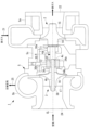
図1に示すように、排気タービン過給機とされた過給機1は、例えば船舶の主機とされたディーゼルエンジンに用いられる。過給機1は、タービン2と、コンプレッサ3と、回転軸4と、これらを収容するハウジング5とを備えている。なお、過給機1は、主機に限らず補機に用いても良い。
Hereinafter, an embodiment of the present invention will be described with reference to the drawings.
As shown in Fig. 1, a turbocharger 1 serving as an exhaust turbocharger is used in, for example, a diesel engine serving as the main engine of a ship. The turbocharger 1 includes a
ハウジング5は、内部が中空に形成され、タービン2を収容するタービンハウジング5aと、コンプレッサ3を収容するコンプレッサハウジング5bと、回転軸4を収容する軸受ハウジング5cとを有している。軸受ハウジング5cは、タービンハウジング5aとコンプレッサハウジング5bとの間に位置している。
The
回転軸4の中心軸線CL方向における一端部(図1において右端部)には、タービン2のタービンホイール14が固定されている。タービンホイール14には、複数のタービン翼15が周方向に所定間隔で設けられている。回転軸4の中心軸線CL方向における他端部(図1において左端部)には、コンプレッサ3のコンプレッサ羽根車16が固定されている。コンプレッサ羽根車16には、複数のブレード17が周方向に所定間隔で設けられている。
The
回転軸4は、タービン2側でタービン側ジャーナル軸受11によって中心軸線CL回りに回転自在に支持され、コンプレッサ3側でコンプレッサ側ジャーナル軸受(軸受)12により中心軸線CL回りに回転自在に支持されている。コンプレッサ側ジャーナル軸受12は、後述するようにスラスト軸受としての機能も有している。
The rotating
タービンハウジング5aには、タービン翼15に対する排ガスの入口通路21と排ガスの出口通路22が設けられている。ディーゼルエンジンの排ガスが入口通路21から導かれてタービン翼15を通過する際に排ガスのエネルギーがタービン2の回転エネルギーに変換され、回転軸4が中心軸線CL回りに回転する。
The
コンプレッサハウジング5bには、コンプレッサ羽根車16に対する空気の吸入口24と、圧縮空気を吐出する吐出口25とが設けられている。タービン2によって得られた回転動力によってコンプレッサ羽根車16が回転し、吸入口24から吸入された空気がコンプレッサ羽根車16のブレード17を通過する際に圧縮される。コンプレッサ3によって圧縮された圧縮空気は、吐出口25からディーゼルエンジンに燃焼用空気として導かれる。
The
軸受ハウジング5cには、軸受11,12等の各所へ潤滑油を供給する潤滑油供給経路30が設けられている。潤滑油供給経路30のタービン側潤滑油供給経路30aは、タービン側ジャーナル軸受11の外周側に接続されている。コンプレッサ側潤滑油供給経路30bは、コンプレッサ側ジャーナル軸受12の外周側に接続されている。
The bearing
<軸受構造>
次に、コンプレッサ側ジャーナル軸受12周りの軸受構造について説明する。
回転軸4は、タービン2側の大径部4aと、コンプレッサ3側の小径部4bとを備えている。大径部4aと小径部4bとは、段差部4cによって接続されている。段差部4cは、中心軸線CLに直交する面を備えている。
<Bearing structure>
Next, the bearing structure around the compressor side journal bearing 12 will be described.
The rotating
コンプレッサ側ジャーナル軸受12の内周側には、円筒スリーブ(スリーブ)32が設けられている。円筒スリーブ32は、円筒形状とされ、回転軸4の小径部4bを包囲するように挿入されている。円筒スリーブ32の外周とコンプレッサ側ジャーナル軸受12の内周との間にはラジアル隙間が形成されており、このラジアル隙間に潤滑油が導かれて回転軸4のラジアル方向が支持されるようになっている。
A cylindrical sleeve (sleeve) 32 is provided on the inner periphery of the compressor-side journal bearing 12. The
コンプレッサ側ジャーナル軸受12の両側には、スラストカラー(カラー)34a,34bがそれぞれ設けられている。各スラストカラー34a,34bは、円板形状とされており、各スラストカラー34a,34bの中心を貫通するように回転軸4の小径部4bが挿入されている。各スラストカラー34a,34bの外径は、円筒スリーブ32の外径よりも大きい。すなわち、円筒スリーブ32の両端に各スラストカラー34a,34bが径方向に突出した状態とされている。各スラストカラー34a,34bの端面は、円筒スリーブ32の両端に対してそれぞれ当接している。
Thrust collars (collars) 34a, 34b are provided on both sides of the compressor-side journal bearing 12. Each
円筒スリーブ32の中心軸線CL方向の寸法は、コンプレッサ側ジャーナル軸受12の中心軸線CL方向の寸法よりも大きい。このため、円筒スリーブ32よりも中心軸線CL方向の寸法が短いコンプレッサ側ジャーナル軸受12と各スラストカラー34a,34bとの間には、所定のスラスト隙間が形成されている。このスラスト隙間に潤滑油が導かれて、回転軸4のスラスト方向が支持されるようになっている。
The dimension of the
円筒スリーブ32と両側のスラストカラー34a,34bとで囲まれた領域に位置するように、コンプレッサ側ジャーナル軸受12が配置されている。コンプレッサ側ジャーナル軸受12は、軸受ハウジング5c側に周方向の回動を制限するように保持されている。
The compressor side journal bearing 12 is arranged so as to be located in the area surrounded by the
コンプレッサ側ジャーナル軸受12の両端部には、各スラストカラー34a,34bと対向する面に、油溝(図示せず)が形成されている。油溝は、所定間隔を空けて周方向に複数設けられている。これら油溝に潤滑油が貯留されて液膜を形成することによって、スラストカラー34a,34bからコンプレッサ側ジャーナル軸受12に加わるスラスト力が支持されるようになっている。このように、コンプレッサ側ジャーナル軸受12は、両端部に油溝を備えることによってスラストパッドの機能も備えている。
Oil grooves (not shown) are formed on both ends of the compressor-side journal bearing 12 on the surfaces facing the
タービン2側のスラストカラー34aのタービン2側の側端面は、回転軸4の段差部4cに当接している。すなわち、タービン2側のスラストカラー34aは、段差部4cに突き当たって中心軸線CL方向のタービン2側にはそれ以上は移動できないようになっている。
The
コンプレッサ3側のスラストカラー34bのコンプレッサ3側の側部は、中間スリーブ36の端部に当接している。中間スリーブ36は、円筒形状とされ、回転軸4を包囲するように配置されている。中間スリーブ36のコンプレッサ3側の端部は、コンプレッサ羽根車16の端部に当接している。
The
コンプレッサ羽根車16の先端側(吸入側)には、固定ナット(固定具)38が設けられている。固定ナット38は、回転軸4の小径部4bの先端(図1において左端)に形成された雄ネジに対して螺合される。固定ナット38を締め付けることにより、コンプレッサ羽根車16、中間スリーブ36、スラストカラー34b、円筒スリーブ32及びスラストカラー34aを順に回転軸4の段差部4cに対して押し込むようになっている。このように固定ナット38を締め付けることによって、コンプレッサ羽根車16、中間スリーブ36、スラストカラー34b、円筒スリーブ32及びスラストカラー34aを回転軸4と一体化している。これにより、コンプレッサ羽根車16、中間スリーブ36、円筒スリーブ32及びスラストカラー34a,34bは、回転軸4とともに回転するようになっている。
A fixed nut (fixing device) 38 is provided on the tip side (suction side) of the
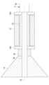
図2には、上述したような、コンプレッサ羽根車16、中間スリーブ36、スラストカラー34b、円筒スリーブ32及びスラストカラー34aの位置関係が簡略化して示されている。
Figure 2 shows a simplified diagram of the positional relationship between the
円筒スリーブ32の外径は、回転軸4の大径部4aの外径と同等とされていることが好ましい。これにより、大径部4aを軸支するタービン側ジャーナル軸受11の内径と、コンプレッサ側ジャーナル軸受12の内径とを同等とすることができる。
The outer diameter of the
図2には、コンプレッサ側潤滑油供給経路30b(図1参照)によって導かれた潤滑油の経路が示されている。潤滑油は、コンプレッサ側ジャーナル軸受12の半径方向に形成され、コンプレッサ側ジャーナル軸受12の内周側に開口する潤滑油供給穴を矢印A1のように通り、矢印A2のように両側に分かれてコンプレッサ側ジャーナル軸受12の内周と円筒スリーブ32の外周との間のラジアル隙間を中心軸線CL方向に流れる。その後、矢印A3のように、コンプレッサ側ジャーナル軸受12とスラストカラー34a,34bとの間の各スラスト隙間を流れる。このように、潤滑油は、ラジアル隙間を流れた後にスラスト隙間を流れるようになっている。
Figure 2 shows the path of the lubricating oil guided by the compressor side lubricating
上述したコンプレッサ側ジャーナル軸受12周りの軸受構造は、以下のように組み立てられる。 The bearing structure around the compressor side journal bearing 12 described above is assembled as follows.
回転軸4の小径部4bに対して、タービン2側のスラストカラー34aを挿入し、段差部4cに当接させる(当接工程)。
The
そして、コンプレッサ側ジャーナル軸受12が嵌め合わされた円筒スリーブ32、コンプレッサ3側のスラストカラー34b、中間スリーブ36及びコンプレッサ羽根車16を順に挿入する。このようにして、両スラストカラー34a,34b間にコンプレッサ側ジャーナル軸受12が位置するように配置する(配置工程)。
Then, the
その後、固定ナット38を回転軸4の小径部4bに対して螺合することによって、コンプレッサ羽根車16、中間スリーブ36、コンプレッサ3側のスラストカラー34b、円筒スリーブ32、タービン2側のスラストカラー34aを段差部4cに当てつつ押し込んで固定する(固定工程)。これにより、コンプレッサ羽根車16、中間スリーブ36、コンプレッサ3側のスラストカラー34b、円筒スリーブ32及びタービン2側のスラストカラー34aが回転軸4と一体化して回転軸4とともに回転するようになる。
Then, the fixing
以上の通り、本実施形態によれば、以下の作用効果を奏する。
回転軸4とともに回転する円筒スリーブ32と、円筒スリーブ32の両端に当接するように回転軸4と共に回転するスラストカラー34a,34bを設けた。そして、円筒スリーブ32の外周側でかつ両スラストカラー34a,34b間に挟まれるようにコンプレッサ側ジャーナル軸受12を設けることとした。これにより、コンプレッサ側ジャーナル軸受12は、円筒スリーブ32を介して回転軸4のラジアル方向を支持することができ、かつ、スラストカラー34a,34bを介して回転軸4のスラスト方向を支持することができる。これにより、1つのコンプレッサ側ジャーナル軸受12でジャーナル軸受とスラスト軸受の機能を持たせることができるので、部品点数を低減でき、また小型化を実現することができる。
また、円筒スリーブ32によってスラストカラー34a,34b間の距離が決まるので、中心軸線CL方向におけるコンプレッサ側ジャーナル軸受12と各スラストカラー34a,34bとの間のスラスト隙間を適切に管理することができる。
As described above, according to the present embodiment, the following advantageous effects are obtained.
A
Furthermore, since the distance between the
コンプレッサ側ジャーナル軸受12の両端部に油溝を形成することとした。これにより、潤滑油がコンプレッサ側ジャーナル軸受12の両端部に導かれることでコンプレッサ側ジャーナル軸受12の両端部をスラストパッドとして用いることができる。したがって、コンプレッサ側ジャーナル軸受12とは別の部品としてスラストパッドを設ける必要がないので、部品点数を低減することができる。 Oil grooves are formed at both ends of the compressor side journal bearing 12. This allows lubricating oil to be guided to both ends of the compressor side journal bearing 12, allowing both ends of the compressor side journal bearing 12 to be used as thrust pads. This eliminates the need to provide thrust pads as separate parts from the compressor side journal bearing 12, reducing the number of parts.
下流側がコンプレッサ側ジャーナル軸受12の内周側に開口する潤滑油供給穴が形成されているので、潤滑油はコンプレッサ側ジャーナル軸受12の内周側に流出(図2の矢印A1参照)した後に、コンプレッサ側ジャーナル軸受12の内周と円筒スリーブ32の外周との間のラジアル隙間を通り(図2の矢印A2参照)、その後にコンプレッサ側ジャーナル軸受12の端部と各スラストカラー34a,34bとの間のスラスト隙間を流れる(図2の矢印A3参照)。このように、潤滑油はラジアル隙間を通過しながら摩擦熱によって加熱されて粘度が低下した後に、スラスト隙間を流れることになる。このように温度上昇により潤滑油の粘度を下げることで、スラスト隙間で生じる機械損失を低減することができる。
Since a lubricating oil supply hole is formed whose downstream side opens to the inner periphery side of the compressor side journal bearing 12, the lubricating oil flows out to the inner periphery side of the compressor side journal bearing 12 (see arrow A1 in FIG. 2), then passes through the radial gap between the inner periphery of the compressor side journal bearing 12 and the outer periphery of the cylindrical sleeve 32 (see arrow A2 in FIG. 2), and then flows through the thrust gap between the end of the compressor side journal bearing 12 and each thrust
回転軸4の小径部4bに取り付けられた固定ナット38によって、スラストカラー34a,34b及び円筒スリーブ32を回転軸4の段差部4c側に向けて押圧することとした。これにより、スラストカラー34a,34b及び円筒スリーブ32が回転軸4と一体に回転するように固定される。
また、固定ナット38と段差部4cとの間で、回転軸4の小径部4bに張力がかかることになる。小径部4bは大径部4aに比べて弾性変形による伸びが大きいので、スラストカラー34a,34b及び円筒スリーブ32に対して締め代(伸び代)を大きくでき、締付のロバスト性を向上させることができる。
The fixing
Furthermore, tension is applied to the
円筒スリーブ32の外径を回転軸4の大径部4aと同等とすることによって、コンプレッサ側ジャーナル軸受12の内径と、タービン側ジャーナル軸受11の内径とを同等とすることができる。これにより、コンプレッサ側ジャーナル軸受12とタービン側ジャーナル軸受11の内径を共通で管理することができる。
By making the outer diameter of the
また、円筒スリーブ32の半径方向の厚さを適宜調整することによって、回転軸4の小径部4bの径を変更することができる。これにより、固定ナット38で締め付けた際の小径部4bの伸び量を調整できることができる。また、タービン2側のスラストカラー34aと回転軸4の段差部4cとの接触面積を調整することで、摩擦力を適切に設定することができる。
The diameter of the
<変形例>
なお、本実施形態は、図3のように変形することができる。
図3に示すように、ジャーナル軸受を1つとしても良い。具体的には、図2に示したコンプレッサ側ジャーナル軸受12を中心軸線CL方向に延長形成したコンプレッサ側ジャーナル軸受12’とし、図2に示した円筒スリーブ32を中心軸線CL方向に延長形成した円筒スリーブ32’とする。これに伴い、小径部4b’も中心軸線CL方向に延長する。これにより、1つのコンプレッサ側ジャーナル軸受12’によって回転軸4の中心軸線CL回りの振れ回りを支持することができるので、図2に示したタービン側ジャーナル軸受11を省略することができる。
<Modification>
This embodiment can be modified as shown in FIG.
As shown in Fig. 3, the number of journal bearings may be one. Specifically, the compressor side journal bearing 12 shown in Fig. 2 is extended in the direction of the central axis CL to form a compressor side journal bearing 12', and the
なお、上述した実施形態では、過給機1の適用先として舶用主機として用いられるディーゼルエンジンとしたが、本発明はこれに限定されるものではなく、例えば舶用主機以外のディーゼルエンジンに用いることができ、また、ディーゼルエンジン以外の内燃機関に用いることもできる。 In the above-described embodiment, the turbocharger 1 is applied to a diesel engine used as a marine main engine, but the present invention is not limited to this and can be used, for example, in diesel engines other than marine main engines, and can also be used in internal combustion engines other than diesel engines.
1 過給機
2 タービン
3 コンプレッサ
4 回転軸
4a 大径部
4b,4b’ 小径部
4c 段差部
5 ハウジング
5a タービンハウジング
5b コンプレッサハウジング
5c 軸受ハウジング
11 タービン側ジャーナル軸受
12,12’ コンプレッサ側ジャーナル軸受
14 タービンホイール
15 タービン翼
16 コンプレッサ羽根車
17 ブレード
21 入口通路
22 出口通路
24 吸入口
25 吐出口
30 潤滑油供給経路
30a タービン側潤滑油供給経路
30b コンプレッサ側潤滑油供給経路
32,32’ 円筒スリーブ(スリーブ)
34a (タービン側の)スラストカラー
34b (コンプレッサ側の)スラストカラー
36 中間スリーブ
38 固定ナット(固定具)
CL 中心軸線
Reference Signs List 1
34a (turbine side) thrust
CL central axis
Claims (5)
前記スリーブの前記中心軸線方向における両端に対して当接するようにそれぞれ設けられ、前記スリーブよりも大径とされ、前記回転軸とともに回転するカラーと、
前記スリーブの外周側でかつ各前記カラーの間に配置された1つの軸受であり、前記スリーブを介して前記回転軸のラジアル方向を支持するジャーナル軸受とされるとともに、前記カラーを介して前記回転軸のスラスト方向を支持するスラスト軸受とされている軸受構造と、
羽根車と、
前記羽根車が取り付けられ、小径部と、大径部と、該小径部と該大径部とを接続する段差部とを備えた回転軸と、
前記大径部に設けられた大径部側ジャーナル軸受と、
を備え、
前記スリーブ及び各前記カラーは、前記小径部に設けられ、
前記大径部側の前記カラーは、前記段差部に当接するように設けられ、
前記軸受構造は、前記回転軸を支持し、
前記スリーブの外径は、前記大径部の外径と同じとされ、
前記1つの軸受の内径は、前記大径部側ジャーナル軸受の内径と同じとされている過給機。 a sleeve provided to surround an outer periphery of a rotating shaft that rotates about a central axis and rotates together with the rotating shaft;
a collar provided to abut against both ends of the sleeve in the central axis direction, the collar having a larger diameter than the sleeve, and the collar rotating together with the rotating shaft;
a bearing structure including one bearing disposed on the outer circumferential side of the sleeve and between the collars, the bearing serving as a journal bearing for supporting the radial direction of the rotating shaft via the sleeve and a thrust bearing for supporting the thrust direction of the rotating shaft via the collar;
An impeller,
a rotating shaft to which the impeller is attached and which has a small diameter portion, a large diameter portion, and a step portion connecting the small diameter portion and the large diameter portion;
a large diameter portion side journal bearing provided in the large diameter portion;
Equipped with
The sleeve and each of the collars are provided on the small diameter portion,
The collar on the large diameter portion side is provided so as to abut against the step portion,
the bearing structure supports the rotating shaft,
The outer diameter of the sleeve is the same as the outer diameter of the large diameter portion,
A turbocharger, wherein an inner diameter of the one bearing is the same as an inner diameter of the large diameter portion side journal bearing.
前記羽根車が取り付けられ、中心軸線回りに回転する回転軸と、
前記回転軸を軸支する軸受構造と、
を備えた過給機の組立方法であって、
前記回転軸は、小径部と、大径部側ジャーナル軸受が設けられた大径部と、該小径部と該大径部とを接続する段差部とを備え、
前記軸受構造は、前記回転軸の外周を包囲するスリーブと、前記スリーブの前記中心軸線方向における両端に対して当接するようにそれぞれ設けられ、前記スリーブよりも大径とされたカラーと、前記スリーブの外周側でかつ各前記カラーの間に配置された軸受と、
を備え、
前記軸受は、1つの軸受であり、前記スリーブを介して前記回転軸のラジアル方向を支持するジャーナル軸受とされるとともに、前記カラーを介して前記回転軸のスラスト方向を支持するスラスト軸受とされ、
前記小径部に対して、前記カラー及び前記スリーブを挿入するとともに、両前記カラー間に前記軸受を配置する配置工程と、
一方の前記カラーを前記段差部に当接させる当接工程と、
前記小径部に対して固定具を固定することによって、前記羽根車、前記カラー及び前記スリーブを前記段差部に押し込んで固定する固定工程と、
を有し、
前記スリーブ及び各前記カラーは、前記小径部に設けられ、
前記大径部側の前記カラーは、前記段差部に当接するように設けられ、
前記スリーブの外径は、前記大径部の外径と同じとされ、
前記軸受の内径は、前記大径部側ジャーナル軸受の内径と同じとされている過給機の組立方法。 An impeller,
a rotating shaft to which the impeller is attached and which rotates about a central axis;
A bearing structure that supports the rotating shaft;
A method for assembling a turbocharger comprising:
the rotating shaft includes a small diameter portion, a large diameter portion provided with a large diameter portion -side journal bearing, and a step portion connecting the small diameter portion and the large diameter portion,
The bearing structure includes a sleeve surrounding an outer periphery of the rotating shaft, collars provided to abut against both ends of the sleeve in the central axis direction and having a larger diameter than the sleeve, and bearings disposed on the outer periphery of the sleeve and between the collars,
Equipped with
the bearing is a single bearing, which is a journal bearing that supports the radial direction of the rotating shaft via the sleeve, and a thrust bearing that supports the thrust direction of the rotating shaft via the collar,
an arrangement step of inserting the collar and the sleeve into the small diameter portion and arranging the bearing between the collars;
a contact step of contacting one of the collars with the step portion;
a fixing step of fixing the impeller, the collar, and the sleeve to the stepped portion by fixing a fixing tool to the small diameter portion;
having
The sleeve and each of the collars are provided on the small diameter portion,
The collar on the large diameter portion side is provided so as to abut against the step portion,
The outer diameter of the sleeve is the same as the outer diameter of the large diameter portion,
An assembly method for a turbocharger, wherein an inner diameter of the bearing is the same as an inner diameter of the large diameter portion side journal bearing.
Priority Applications (7)
| Application Number | Priority Date | Filing Date | Title |
|---|---|---|---|
| JP2019024518A JP7588948B2 (en) | 2019-02-14 | 2019-02-14 | Turbocharger and method for assembling turbocharger |
| US17/430,562 US11732607B2 (en) | 2019-02-14 | 2020-01-28 | Bearing structure, turbocharger having the same, and assembly method of turbocharger |
| KR1020217025149A KR102646973B1 (en) | 2019-02-14 | 2020-01-28 | Bearing structure, supercharger equipped with the same, and method of assembling the supercharger |
| PCT/JP2020/002954 WO2020166318A1 (en) | 2019-02-14 | 2020-01-28 | Bearing structure, supercharger having same, and assembly method for supercharger |
| CN202080013707.XA CN113423930A (en) | 2019-02-14 | 2020-01-28 | Bearing structure, supercharger provided with same, and method for assembling supercharger |
| FIEP20755528.5T FI3910173T3 (en) | 2019-02-14 | 2020-01-28 | Turbocharger with bearing structure, and assembly method for turbocharger |
| EP20755528.5A EP3910173B1 (en) | 2019-02-14 | 2020-01-28 | Turbocharger with bearing structure, and assembly method for turbocharger |
Applications Claiming Priority (1)
| Application Number | Priority Date | Filing Date | Title |
|---|---|---|---|
| JP2019024518A JP7588948B2 (en) | 2019-02-14 | 2019-02-14 | Turbocharger and method for assembling turbocharger |
Publications (2)
| Publication Number | Publication Date |
|---|---|
| JP2020133687A JP2020133687A (en) | 2020-08-31 |
| JP7588948B2 true JP7588948B2 (en) | 2024-11-25 |
Family
ID=72045567
Family Applications (1)
| Application Number | Title | Priority Date | Filing Date |
|---|---|---|---|
| JP2019024518A Active JP7588948B2 (en) | 2019-02-14 | 2019-02-14 | Turbocharger and method for assembling turbocharger |
Country Status (7)
| Country | Link |
|---|---|
| US (1) | US11732607B2 (en) |
| EP (1) | EP3910173B1 (en) |
| JP (1) | JP7588948B2 (en) |
| KR (1) | KR102646973B1 (en) |
| CN (1) | CN113423930A (en) |
| FI (1) | FI3910173T3 (en) |
| WO (1) | WO2020166318A1 (en) |
Families Citing this family (1)
| Publication number | Priority date | Publication date | Assignee | Title |
|---|---|---|---|---|
| CN117052785A (en) * | 2023-08-03 | 2023-11-14 | 马鞍山经纬回转支承股份有限公司 | Maintenance-free sliding slewing bearing |
Citations (4)
| Publication number | Priority date | Publication date | Assignee | Title |
|---|---|---|---|---|
| JP2005030382A (en) | 2003-06-18 | 2005-02-03 | Komatsu Ltd | Compressor for turbomachine and compressor impeller thereof |
| JP2009174358A (en) | 2008-01-23 | 2009-08-06 | Ihi Corp | Supercharger |
| WO2014103004A1 (en) | 2012-12-28 | 2014-07-03 | 株式会社日立製作所 | Duplex bearing device |
| JP2014149058A (en) | 2013-02-04 | 2014-08-21 | Taiho Kogyo Co Ltd | Thrust bearing |
Family Cites Families (37)
| Publication number | Priority date | Publication date | Assignee | Title |
|---|---|---|---|---|
| DE6608771U (en) * | 1966-08-24 | 1971-11-11 | Wallace Murray Corp | BEARING FOR FAST ROTATING MACHINERY, PREFERABLY TURBOCHARGER. |
| JPS50149710U (en) * | 1974-05-29 | 1975-12-12 | ||
| JPS5267442A (en) | 1975-12-01 | 1977-06-03 | Hitachi Ltd | Taper land thrust bearing |
| US4256441A (en) * | 1979-06-19 | 1981-03-17 | Wallace-Murray Corporation | Floating ring bearing structure and turbocharger employing same |
| JPS5887935U (en) * | 1981-12-10 | 1983-06-15 | 石川島播磨重工業株式会社 | Turbocharger thrust bearing |
| JPS5890327U (en) * | 1981-12-14 | 1983-06-18 | 日産自動車株式会社 | Turbo supercharger bearing device |
| JPS61202648U (en) * | 1985-06-10 | 1986-12-19 | ||
| JPS61202649U (en) * | 1985-06-10 | 1986-12-19 | ||
| JPS62143819U (en) * | 1986-03-04 | 1987-09-10 | ||
| JPS62143818U (en) * | 1986-03-04 | 1987-09-10 | ||
| JPS6376913A (en) * | 1986-09-19 | 1988-04-07 | Hitachi Ltd | Doubel thrust bearing with journal bearing |
| JP2505916B2 (en) | 1989-08-11 | 1996-06-12 | 株式会社荏原製作所 | Bearing structure |
| EP0412509A3 (en) | 1989-08-11 | 1992-02-26 | Ebara Corporation | Bearing structure |
| JPH07217441A (en) * | 1994-02-02 | 1995-08-15 | Taiho Kogyo Co Ltd | Non-contact sealing device for turbocharger |
| US5857332A (en) * | 1996-12-20 | 1999-01-12 | Turbodyne Systems, Inc. | Bearing systems for motor-assisted turbochargers for internal combustion engines |
| US6017184A (en) * | 1997-08-06 | 2000-01-25 | Allied Signal Inc. | Turbocharger integrated bearing system |
| JP4008074B2 (en) * | 1997-09-03 | 2007-11-14 | Thk株式会社 | Grinding equipment |
| US6418722B1 (en) * | 2001-04-19 | 2002-07-16 | Honeywell International, Inc. | Turbocharger bearing system |
| JP2004332885A (en) | 2003-05-12 | 2004-11-25 | Nippon Densan Corp | Gas dynamic-pressure bearing and spindle motor |
| US7670056B2 (en) * | 2007-03-22 | 2010-03-02 | Honeywell International Inc. | Stepped outer diameter semi-floating bearing |
| CN201407202Y (en) | 2009-03-14 | 2010-02-17 | 广东美的电器股份有限公司 | Gear drive mechanism of centrifugal compressor |
| GB2503620B (en) * | 2011-04-08 | 2017-12-20 | Dresser-Rand Company | Self-lubricating snubber bearing |
| US8845271B2 (en) * | 2011-05-31 | 2014-09-30 | William E. Woollenweber | Turbocharger bearing system |
| JP5524427B2 (en) * | 2011-12-27 | 2014-06-18 | 三菱重工業株式会社 | Thrust bearing device for turbocharger |
| WO2014038080A1 (en) * | 2012-09-10 | 2014-03-13 | 株式会社日立製作所 | Thrust bearing device and rotating machine using same |
| KR20150102043A (en) * | 2012-12-27 | 2015-09-04 | 보르그워너 인코퍼레이티드 | Fluid film conical or hemispherical floating ring bearings |
| US20170067472A1 (en) * | 2014-02-25 | 2017-03-09 | Borgwarner Inc. | Thrust bearing assembly including lined bearing surfaces |
| JP6345470B2 (en) | 2014-04-14 | 2018-06-20 | 大豊工業株式会社 | Thrust bearing |
| DE112015004493T5 (en) * | 2014-09-30 | 2017-06-29 | Ihi Corporation | WAREHOUSE AND TURBOLADER |
| US10641330B2 (en) * | 2016-03-01 | 2020-05-05 | Mitsubishi Heavy Industries Engine & Turbocharger, Ltd. | Bearing device and exhaust turbine supercharger |
| US20190078509A1 (en) | 2016-03-01 | 2019-03-14 | Mitsubishi Heavy Industries Engine & Turbocharger, Ltd. | Bearing device and exhaust turbine supercharger |
| DE202016105071U1 (en) * | 2016-09-13 | 2016-11-03 | Martin Berger | Hydrodynamic plain bearing and exhaust gas turbocharger |
| DE112017005884T5 (en) * | 2016-11-21 | 2019-08-08 | Ihi Corporation | Bearing structure and turbocharger |
| JP2018145942A (en) | 2017-03-08 | 2018-09-20 | 三菱重工業株式会社 | Assembly method for supercharger, compressor and supercharger |
| DE102018130706A1 (en) * | 2018-12-03 | 2020-06-04 | Martin Berger | Exhaust gas turbocharger with a hydrodynamic plain bearing or hydrodynamic plain bearing |
| DE102018130709A1 (en) * | 2018-12-03 | 2020-06-04 | Martin Berger | Exhaust gas turbocharger with a hydrodynamic plain bearing or hydrodynamic plain bearing |
| CN113260796B (en) * | 2019-01-07 | 2023-06-27 | 三菱重工发动机和增压器株式会社 | Bearing device and turbocharger having the same |
-
2019
- 2019-02-14 JP JP2019024518A patent/JP7588948B2/en active Active
-
2020
- 2020-01-28 WO PCT/JP2020/002954 patent/WO2020166318A1/en not_active Ceased
- 2020-01-28 EP EP20755528.5A patent/EP3910173B1/en active Active
- 2020-01-28 CN CN202080013707.XA patent/CN113423930A/en active Pending
- 2020-01-28 FI FIEP20755528.5T patent/FI3910173T3/en active
- 2020-01-28 US US17/430,562 patent/US11732607B2/en active Active
- 2020-01-28 KR KR1020217025149A patent/KR102646973B1/en active Active
Patent Citations (4)
| Publication number | Priority date | Publication date | Assignee | Title |
|---|---|---|---|---|
| JP2005030382A (en) | 2003-06-18 | 2005-02-03 | Komatsu Ltd | Compressor for turbomachine and compressor impeller thereof |
| JP2009174358A (en) | 2008-01-23 | 2009-08-06 | Ihi Corp | Supercharger |
| WO2014103004A1 (en) | 2012-12-28 | 2014-07-03 | 株式会社日立製作所 | Duplex bearing device |
| JP2014149058A (en) | 2013-02-04 | 2014-08-21 | Taiho Kogyo Co Ltd | Thrust bearing |
Also Published As
| Publication number | Publication date |
|---|---|
| EP3910173A1 (en) | 2021-11-17 |
| KR20210110711A (en) | 2021-09-08 |
| JP2020133687A (en) | 2020-08-31 |
| US20220127972A1 (en) | 2022-04-28 |
| WO2020166318A1 (en) | 2020-08-20 |
| KR102646973B1 (en) | 2024-03-12 |
| FI3910173T3 (en) | 2025-01-15 |
| EP3910173A4 (en) | 2021-11-17 |
| EP3910173B1 (en) | 2024-12-11 |
| US11732607B2 (en) | 2023-08-22 |
| CN113423930A (en) | 2021-09-21 |
Similar Documents
| Publication | Publication Date | Title |
|---|---|---|
| EP1273765B1 (en) | Turbocharger shaft dual phase seal | |
| CN107044304B (en) | Bearing outer race retention during high load events | |
| US9982557B2 (en) | VTG mechanism assembly using wave spring | |
| CN103080499B (en) | Fixed vane turbocharger | |
| US9759223B2 (en) | Bearing system for a turbocharger with an internal electric motor | |
| US4519747A (en) | Method for assembling an impeller onto a turboshaft | |
| JP6806150B2 (en) | Bearings and turbochargers | |
| CN108799399B (en) | Squeeze film damper assembly | |
| JPWO2015128958A1 (en) | Centrifugal compressor, turbocharger including the centrifugal compressor, and method for manufacturing the centrifugal compressor | |
| CN114555927A (en) | Turbomachine fan assembly comprising a roller bearing and a double row ball bearing in oblique contact | |
| EP1676016B1 (en) | Turbocharger with a thin-walled turbine housing having a floating flange attachment to the centre housing | |
| JP2007285252A (en) | Turbocharger | |
| KR20040036657A (en) | Compressor wheel assembly | |
| JP7588948B2 (en) | Turbocharger and method for assembling turbocharger | |
| JP7099625B2 (en) | Turbine housing and turbocharger | |
| JP5230590B2 (en) | Exhaust inlet casing of exhaust turbine supercharger | |
| US20190107052A1 (en) | Turbocharger | |
| US11319964B2 (en) | Turbocharger and bearing housing therefor | |
| JP2009257258A (en) | Bearing housing for exhaust gas turbine supercharger | |
| US20250043817A1 (en) | Airfoil bearing arrangement and method for making the same | |
| JP2907086B2 (en) | Centrifugal compressor or centrifugal turbine impeller fixing mechanism | |
| WO2024262099A1 (en) | Rotation device | |
| JP2026051630A (en) | Motor rotor | |
| WO2024237107A1 (en) | Rotary device | |
| JP2022046217A (en) | Turbocharger |
Legal Events
| Date | Code | Title | Description |
|---|---|---|---|
| A711 | Notification of change in applicant |
Free format text: JAPANESE INTERMEDIATE CODE: A711 Effective date: 20200325 |
|
| A521 | Request for written amendment filed |
Free format text: JAPANESE INTERMEDIATE CODE: A523 Effective date: 20211222 |
|
| A621 | Written request for application examination |
Free format text: JAPANESE INTERMEDIATE CODE: A621 Effective date: 20211222 |
|
| A131 | Notification of reasons for refusal |
Free format text: JAPANESE INTERMEDIATE CODE: A131 Effective date: 20230117 |
|
| A601 | Written request for extension of time |
Free format text: JAPANESE INTERMEDIATE CODE: A601 Effective date: 20230315 |
|
| A521 | Request for written amendment filed |
Free format text: JAPANESE INTERMEDIATE CODE: A523 Effective date: 20230511 |
|
| A131 | Notification of reasons for refusal |
Free format text: JAPANESE INTERMEDIATE CODE: A131 Effective date: 20230829 |
|
| A521 | Request for written amendment filed |
Free format text: JAPANESE INTERMEDIATE CODE: A523 Effective date: 20231027 |
|
| A131 | Notification of reasons for refusal |
Free format text: JAPANESE INTERMEDIATE CODE: A131 Effective date: 20231114 |
|
| A521 | Request for written amendment filed |
Free format text: JAPANESE INTERMEDIATE CODE: A523 Effective date: 20240112 |
|
| A131 | Notification of reasons for refusal |
Free format text: JAPANESE INTERMEDIATE CODE: A131 Effective date: 20240402 |
|
| A521 | Request for written amendment filed |
Free format text: JAPANESE INTERMEDIATE CODE: A523 Effective date: 20240603 |
|
| A131 | Notification of reasons for refusal |
Free format text: JAPANESE INTERMEDIATE CODE: A131 Effective date: 20240910 |
|
| A521 | Request for written amendment filed |
Free format text: JAPANESE INTERMEDIATE CODE: A523 Effective date: 20240924 |
|
| TRDD | Decision of grant or rejection written | ||
| A01 | Written decision to grant a patent or to grant a registration (utility model) |
Free format text: JAPANESE INTERMEDIATE CODE: A01 Effective date: 20241015 |
|
| A61 | First payment of annual fees (during grant procedure) |
Free format text: JAPANESE INTERMEDIATE CODE: A61 Effective date: 20241113 |
|
| R150 | Certificate of patent or registration of utility model |
Ref document number: 7588948 Country of ref document: JP Free format text: JAPANESE INTERMEDIATE CODE: R150 |