JP2007285252A - Turbo charger - Google Patents
Turbo charger Download PDFInfo
- Publication number
- JP2007285252A JP2007285252A JP2006115622A JP2006115622A JP2007285252A JP 2007285252 A JP2007285252 A JP 2007285252A JP 2006115622 A JP2006115622 A JP 2006115622A JP 2006115622 A JP2006115622 A JP 2006115622A JP 2007285252 A JP2007285252 A JP 2007285252A
- Authority
- JP
- Japan
- Prior art keywords
- floating bearing
- turbine
- oil supply
- oil
- turbocharger
- Prior art date
- Legal status (The legal status is an assumption and is not a legal conclusion. Google has not performed a legal analysis and makes no representation as to the accuracy of the status listed.)
- Withdrawn
Links
Images


Classifications
-
- F—MECHANICAL ENGINEERING; LIGHTING; HEATING; WEAPONS; BLASTING
- F16—ENGINEERING ELEMENTS AND UNITS; GENERAL MEASURES FOR PRODUCING AND MAINTAINING EFFECTIVE FUNCTIONING OF MACHINES OR INSTALLATIONS; THERMAL INSULATION IN GENERAL
- F16C—SHAFTS; FLEXIBLE SHAFTS; ELEMENTS OR CRANKSHAFT MECHANISMS; ROTARY BODIES OTHER THAN GEARING ELEMENTS; BEARINGS
- F16C37/00—Cooling of bearings
- F16C37/002—Cooling of bearings of fluid bearings
-
- F—MECHANICAL ENGINEERING; LIGHTING; HEATING; WEAPONS; BLASTING
- F16—ENGINEERING ELEMENTS AND UNITS; GENERAL MEASURES FOR PRODUCING AND MAINTAINING EFFECTIVE FUNCTIONING OF MACHINES OR INSTALLATIONS; THERMAL INSULATION IN GENERAL
- F16C—SHAFTS; FLEXIBLE SHAFTS; ELEMENTS OR CRANKSHAFT MECHANISMS; ROTARY BODIES OTHER THAN GEARING ELEMENTS; BEARINGS
- F16C17/00—Sliding-contact bearings for exclusively rotary movement
- F16C17/02—Sliding-contact bearings for exclusively rotary movement for radial load only
-
- F—MECHANICAL ENGINEERING; LIGHTING; HEATING; WEAPONS; BLASTING
- F16—ENGINEERING ELEMENTS AND UNITS; GENERAL MEASURES FOR PRODUCING AND MAINTAINING EFFECTIVE FUNCTIONING OF MACHINES OR INSTALLATIONS; THERMAL INSULATION IN GENERAL
- F16C—SHAFTS; FLEXIBLE SHAFTS; ELEMENTS OR CRANKSHAFT MECHANISMS; ROTARY BODIES OTHER THAN GEARING ELEMENTS; BEARINGS
- F16C17/00—Sliding-contact bearings for exclusively rotary movement
- F16C17/12—Sliding-contact bearings for exclusively rotary movement characterised by features not related to the direction of the load
- F16C17/18—Sliding-contact bearings for exclusively rotary movement characterised by features not related to the direction of the load with floating brasses or brushing, rotatable at a reduced speed
-
- F—MECHANICAL ENGINEERING; LIGHTING; HEATING; WEAPONS; BLASTING
- F16—ENGINEERING ELEMENTS AND UNITS; GENERAL MEASURES FOR PRODUCING AND MAINTAINING EFFECTIVE FUNCTIONING OF MACHINES OR INSTALLATIONS; THERMAL INSULATION IN GENERAL
- F16C—SHAFTS; FLEXIBLE SHAFTS; ELEMENTS OR CRANKSHAFT MECHANISMS; ROTARY BODIES OTHER THAN GEARING ELEMENTS; BEARINGS
- F16C2360/00—Engines or pumps
- F16C2360/23—Gas turbine engines
- F16C2360/24—Turbochargers
Abstract
Description
この発明は、一般的には、ターボチャージャに関し、より特定的には、コンプレッサおよびタービン間を連結するシャフトの軸受けとしてフローティングベアリングを備えるターボチャージャに関する。 The present invention relates generally to a turbocharger, and more particularly to a turbocharger that includes a floating bearing as a bearing for a shaft that connects between a compressor and a turbine.
従来のターボチャージャに関して、たとえば、特開2002−138846号公報には、ターボチャージャのシャフトの振動による騒音の低減と、白煙の発生の防止とを両立することを目的としたターボチャージャの軸受け装置が開示されている(特許文献1)。特許文献1に開示された軸受け装置は、シャフトを回転自在に支承するコンプレッサ側軸受けおよびタービン側軸受けを有する。これらの軸受けは、浮動ブッシュ軸受けから構成されている。コンプレッサ側軸受けは、外径クリアランスが大きく、内径クリアランスが小さくなるか、外径幅が小さく、内径幅が大きくなるように構成されている。タービン側軸受けは、内外径クリアランスが共に小さくなるか、内外径幅が共に大きくなるように構成されている。 Regarding a conventional turbocharger, for example, Japanese Patent Application Laid-Open No. 2002-13884 discloses a turbocharger bearing device for achieving both reduction of noise due to vibration of a shaft of a turbocharger and prevention of generation of white smoke. Is disclosed (Patent Document 1). The bearing device disclosed in Patent Document 1 includes a compressor side bearing and a turbine side bearing that rotatably support a shaft. These bearings are composed of floating bush bearings. The compressor side bearing is configured to have a large outer diameter clearance and a smaller inner diameter clearance, or a smaller outer diameter width and a larger inner diameter width. The turbine-side bearing is configured such that both the inner and outer diameter clearances are reduced or the inner and outer diameter widths are both increased.
また、特開昭58−176418号公報には、ラジアル軸受けのメタル部への潤滑油量を増加させることによって、メタル部の冷却効率やターボチャージャの耐久性を向上させることを目的とした過給機が開示されている(特許文献2)。
上述の特許文献1では、コンプレッサ側軸受けの内外径クリアランスもしくは内外径幅を調整することによって、シャフトの振動を抑え、騒音を低減させる。しかしながら、このような調整によっては、オイルホワールやオイルウィップと呼ばれる油膜の自励振動を抑え、異音を十分に低減させることが難しい。また、内外径クリアランスの調整には、高精度の加工や精密な寸法測定を伴うため、量産性に劣る。一方、排気ガスの影響を受けるタービン側軸受けでは、コンプレッサ側軸受けよりも発熱量が大きくなるため、効率良く冷却される必要がある。 In the above-mentioned Patent Document 1, by adjusting the inner / outer diameter clearance or inner / outer diameter width of the compressor side bearing, shaft vibration is suppressed and noise is reduced. However, with such adjustment, it is difficult to suppress the self-excited vibration of the oil film called oil whirl or oil whip and sufficiently reduce abnormal noise. In addition, the adjustment of the inner and outer diameter clearances is accompanied by high-precision processing and precise dimensional measurement, which is inferior in mass productivity. On the other hand, the turbine-side bearing affected by the exhaust gas has a larger amount of heat generation than the compressor-side bearing, and therefore needs to be cooled efficiently.
そこでこの発明の目的は、上記の課題を解決することであり、冷却性能の維持を図りつつ、異音の発生が十分に抑制されるターボチャージャを提供することである。 Accordingly, an object of the present invention is to solve the above-described problem and to provide a turbocharger in which the generation of abnormal noise is sufficiently suppressed while maintaining the cooling performance.
この発明に従ったターボチャージャは、所定の軸に沿って延びるシャフトと、シャフトを取り囲むように設けられたハウジングと、所定の軸方向に並ぶ第1および第2のフローティングベアリングとを備える。シャフトは、所定の軸方向に離間したコンプレッサとタービンとを連結する。第1および第2のフローティングベアリングは、ハウジングおよびシャフトの各々との間の隙間にオイルを介在させて浮遊し、ハウジングに対してシャフトを回転自在に支持する。第1のフローティングベアリングは、タービン側に配設されている。第2のフローティングベアリングは、コンプレッサ側に配設されている。ターボチャージャは、さらに、第1のフローティングベアリングの所定の軸周りの回転を規制する第1の回転止め部材を備える。ハウジングには、第1のフローティングベアリングに供給するオイルが流れる第1の給油通路と、第2のフローティングベアリングに供給するオイルが流れる第2の給油通路とが形成されている。第1の給油通路の断面積は、第2の給油通路の断面積よりも大きい。 A turbocharger according to the present invention includes a shaft extending along a predetermined axis, a housing provided so as to surround the shaft, and first and second floating bearings arranged in a predetermined axial direction. The shaft connects a compressor and a turbine spaced apart in a predetermined axial direction. The first and second floating bearings float with oil interposed in gaps between the housing and the shaft, and rotatably support the shaft with respect to the housing. The first floating bearing is disposed on the turbine side. The second floating bearing is disposed on the compressor side. The turbocharger further includes a first rotation stop member that restricts the rotation of the first floating bearing around a predetermined axis. A first oil supply passage through which oil supplied to the first floating bearing flows and a second oil supply passage through which oil supplied to the second floating bearing flow are formed in the housing. The cross-sectional area of the first oil supply passage is larger than the cross-sectional area of the second oil supply passage.
このように構成されたターボチャージャによれば、第1の回転止め部材により、第1のフローティングベアリングの回転を規制する。これにより、第1のフローティングベアリングと、ハウジングおよびシャフトの各々との間の隙間に介在するオイルの自励振動を抑えることができる。また、回転が規制され、発熱量が大きくなる第1のフローティングベアリングを、第1の給油通路の断面積を第2の給油通路の断面積よりも大きく設定することによって、効率的に冷却することができる。したがって、本発明によれば、冷却性能の維持を図りつつ、オイルの自励振動に起因する異音の発生を十分に抑制することができる。 According to the turbocharger configured as described above, the rotation of the first floating bearing is restricted by the first rotation stop member. Thereby, the self-excited vibration of the oil interposed in the clearance between the first floating bearing and each of the housing and the shaft can be suppressed. Further, the first floating bearing whose rotation is restricted and the amount of generated heat is increased can be efficiently cooled by setting the cross-sectional area of the first oil supply passage to be larger than the cross-sectional area of the second oil supply passage. Can do. Therefore, according to this invention, generation | occurrence | production of the noise resulting from the self-excited vibration of oil can be fully suppressed, aiming at maintenance of cooling performance.
また、タービンの重量は、コンプレッサの重量よりも大きい。このように構成されたターボチャージャによれば、タービンおよびコンプレッサの重量差により、コンプレッサ側に配設された第2のフローティングベアリングよりもタービン側に配設された第1のフローティングベアリングで、オイルの自励振動が大きくなる傾向が生じる。このため、第1のフローティングベアリングの回転を規制することによって、異音の発生をより効果的に抑制することができる。 Further, the weight of the turbine is larger than the weight of the compressor. According to the turbocharger configured as described above, due to the weight difference between the turbine and the compressor, the first floating bearing disposed on the turbine side rather than the second floating bearing disposed on the compressor side, The self-excited vibration tends to increase. For this reason, generation | occurrence | production of unusual noise can be suppressed more effectively by restrict | limiting rotation of a 1st floating bearing.
また好ましくは、第1のフローティングベアリングには、所定の軸を中心とした半径方向に貫通する給油孔が形成されている。第1の回転止め部材は、第1の給油通路に挿入される一方端と、給油孔に挿入される他方端とを有する円筒形状に形成されている。このように構成されたターボチャージャによれば、第1の回転止め部材によって、第1のフローティングベアリングの回転を規制するとともに、第1の給油通路から第1の給油孔にオイルを流通させることができる。 Preferably, the first floating bearing is formed with an oil supply hole penetrating in a radial direction around a predetermined axis. The first rotation stop member is formed in a cylindrical shape having one end inserted into the first oil supply passage and the other end inserted into the oil supply hole. According to the turbocharger configured as described above, the rotation of the first floating bearing can be regulated by the first rotation stop member, and the oil can be circulated from the first oil supply passage to the first oil supply hole. it can.
また好ましくは、ターボチャージャは、第1および第2のリング部材をさらに備える。第1および第2のリング部材は、第1のフローティングベアリングに当接し、第1のフローティングベアリングの所定の軸方向の移動を規制する。第1のリング部材は、第1のフローティングベアリングとタービンとの間に配設されている。第2のリング部材は、第1のフローティングベアリングに対して第1のリング部材の反対側に配設されている。所定の軸を中心とした半径方向の第1のリング部材の幅は、第2のリング部材の幅よりも大きい。 Preferably, the turbocharger further includes first and second ring members. The first and second ring members abut on the first floating bearing and restrict movement of the first floating bearing in a predetermined axial direction. The first ring member is disposed between the first floating bearing and the turbine. The second ring member is disposed on the opposite side of the first ring member with respect to the first floating bearing. The width of the first ring member in the radial direction around the predetermined axis is larger than the width of the second ring member.
このように構成されたターボチャージャによれば、第1のフローティングベアリングと第1のリング部材とが当接する面積を、第1のフローティングベアリングと第2のリング部材とが当接する面積よりも大きく設定することができる。これにより、第1の給油通路の断面積が第2の給油通路の断面積よりも大きく設定されているにもかかわらず、第1の給油通路から供給されたオイルが、第1のフローティングベアリングと第1のリング部材との間を通ってタービン側に漏れる量を少なくできる。 According to the turbocharger configured as described above, the area where the first floating bearing and the first ring member abut is set larger than the area where the first floating bearing and the second ring member abut. can do. Thereby, although the cross-sectional area of the first oil supply passage is set larger than the cross-sectional area of the second oil supply passage, the oil supplied from the first oil supply passage becomes the first floating bearing. The amount of leakage to the turbine side through the first ring member can be reduced.
また好ましくは、ターボチャージャは、第2のフローティングベアリングの所定の軸周りの回転を規制する第2の回転止め部材をさらに備える。このように構成されたターボチャージャによれば、第2のフローティングベアリングと、ハウジングおよびシャフトの各々との間の隙間に介在するオイルの自励振動を抑え、異音の発生をさらに効果的に抑制することができる。 Preferably, the turbocharger further includes a second rotation stop member that restricts rotation of the second floating bearing around a predetermined axis. According to the turbocharger configured as described above, the self-excited vibration of the oil interposed in the gap between the second floating bearing and each of the housing and the shaft is suppressed, and the generation of abnormal noise is further effectively suppressed. can do.
以上説明したように、この発明に従えば、冷却性能の維持を図りつつ、異音の発生が十分に抑制されるターボチャージャを提供することができる。 As described above, according to the present invention, it is possible to provide a turbocharger in which generation of abnormal noise is sufficiently suppressed while maintaining cooling performance.
この発明の実施の形態について、図面を参照して説明する。なお、以下で参照する図面では、同一またはそれに相当する部材には、同じ番号が付されている。 Embodiments of the present invention will be described with reference to the drawings. In the drawings referred to below, the same or corresponding members are denoted by the same reference numerals.
(実施の形態1)
図1は、この発明の実施の形態1におけるターボチャージャを示す断面図である。図1を参照して、ターボチャージャ10は、車両に搭載されるガソリンエンジンやディーゼルエンジン等の内燃機関の過給機として用いられる。ターボチャージャ10は、排気ガスのエネルギを利用して、吸入空気または混合気を圧縮し、密度の高い空気または混合気を燃焼室に送り込む装置である。
(Embodiment 1)
1 is a cross-sectional view showing a turbocharger according to Embodiment 1 of the present invention. Referring to FIG. 1, a
ターボチャージャ10は、中心軸101に沿って延びるタービンシャフト12と、タービンシャフト12の両端に接続されたコンプレッサ61およびタービン66と、タービンシャフト12の外周上を取り囲むように設けられたセンターハウジング41と、タービンシャフト12を支持するフローティングベアリング21および26と、フローティングベアリング21の回転を規制するピン部材36とを備える。
The
センターハウジング41には、タービン66を収容するタービンハウジング71と、コンプレッサ61を収容するコンプレッサハウジング76とが固定されている。タービンハウジング71およびコンプレッサハウジング76には、それぞれ、渦室72および渦室77が形成されている。
A turbine housing 71 that houses the
コンプレッサ61およびタービン66は、タービンシャフト12によって互いに連結されている。コンプレッサ61およびタービン66は、中心軸101の軸方向に距離を隔てて設けられている。タービン66の重量は、コンプレッサ61の重量よりも大きい。コンプレッサ61は、たとえば、アルミニウムから形成されている。タービン66は、排気ガスに直接、晒され、非常に高温になるため、耐熱性や耐久性を備える超耐熱合金から形成されている。
The
フローティングベアリング21および26は、タービンシャフト12をセンターハウジング41に対して回転自在に支持している。フローティングベアリング21および26により支持されたタービンシャフト12は、コンプレッサ61およびタービン66とともに中心軸101を中心に回転する。
The
フローティングベアリング21および26は、コンプレッサ61とタービン66との間に設けられている。フローティングベアリング21とフローティングベアリング26とは、中心軸101の軸方向に間隔を隔てて設けられている。フローティングベアリング21は、タービン66側に設けられ、フローティングベアリング26は、コンプレッサ61側に設けられている。
The floating
すなわち、タービン66とフローティングベアリング21との間の距離は、相対的に小さく、タービン66とフローティングベアリング26との間の距離は、相対的に大きい。また、コンプレッサ61とフローティングベアリング21との間の距離は、相対的に大きく、コンプレッサ61とフローティングベアリング26との間の距離は、相対的に小さい。言い換えれば、中心軸101の軸方向において、フローティングベアリング21は、タービン66とフローティングベアリング26との間に配置されている。フローティングベアリング26は、コンプレッサ61とフローティングベアリング21との間に配置されている。
That is, the distance between the
ターボチャージャ10は、スラストブッシュ63およびスラストベアリング62をさらに備える。スラストブッシュ63は、タービンシャフト12の外周上に固定されている。スラストブッシュ63は、フローティングベアリング26とコンプレッサ61との間に配置されている。スラストベアリング62は、中心軸101の軸方向に微小な隙間を設けてスラストブッシュ63に係合している。その隙間に潤滑油が供給されることによって、タービンシャフト12は、中心軸101の軸方向に支持されている。
The
センターハウジング41には、オイルが流通する給油通路42が形成されている。給油通路42に流れるオイルは、フローティングベアリング21および26ならびにスラストベアリング62に潤滑油として供給される。また、そのオイルは、回転するタービンシャフト12を冷却する。タービンシャフト12には、センターハウジング41内のオイルがタービンハウジング71内に漏出することを防ぐためのオイルスリンガ67が成形されている。
The
ターボチャージャ10の働きについて簡単に説明すると、エンジンで、燃料と混合され燃焼させられた空気、すなわち排気ガスは、エンジンの各気筒に接続されたエキゾーストマニホールドからタービンハウジング71の渦室72に導かれる。排気ガスは、そこでタービン66を回転させ、その回転力がタービンシャフト12に伝達される。その後、排気ガスは、触媒に導かれ、浄化された状態で車外へと排出される。一方、エンジンに供給するため車外より吸入された空気は、図示しないエアクリーナによってろ過された後、コンプレッサハウジング76内に導かれる。空気は、タービンシャフト12と一体となって回転するコンプレッサ61により加圧され、渦室77に送られる。加圧された空気は、インタークーラーに導かれ、冷却された状態でエンジンのインテークマニホールドへと吸入される。
The operation of the
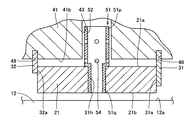
図2は、図1中のターボチャージャに設けられた軸受け機構を詳細に示す断面図である。図3は、図1中のターボチャージャが備えるフローティングベアリングを示す斜視図である。 FIG. 2 is a cross-sectional view showing in detail a bearing mechanism provided in the turbocharger in FIG. FIG. 3 is a perspective view showing a floating bearing provided in the turbocharger in FIG.
図2および図3を参照して、フローティングベアリング21は、外周面21aと内周面21bとを有する円筒形状に形成されている。フローティングベアリング21には、外周面21aから内周面21bまで貫通する給油孔21hが形成されている。給油孔21hは、中心軸101を中心とする半径方向に延びている。給油孔21hは、中心軸101を中心としてその周方向に間隔を隔て、複数形成されている。なお、図中には、6つの給油孔21hが形成される場合が示されているが、給油孔21hの数は、これに限定されるものではない。
Referring to FIGS. 2 and 3, floating
タービンシャフト12は、外周面12aを有する。フローティングベアリング21は、外周面12aと内周面21bとが対向するように、タービンシャフト12に嵌め合わされている。センターハウジング41は、外周面12aに向い合う内周面41bを有する。フローティングベアリング21は、内周面41bと外周面21aとが対向するように、センターハウジング41に嵌め合わされている。外周面12aと内周面21bとの間および内周面41bと外周面21aとの間には、それぞれ、オイルによって満たされる隙間が形成されている。すなわち、フローティングベアリング21は、オイルを介してセンターハウジング41およびタービンシャフト12から浮遊した状態で設けられる。
The
フローティングベアリング26は、フローティングベアリング21と同様の形状を有する。フローティングベアリング26には、複数の給油孔26hが形成されている。フローティングベアリング26は、フローティングベアリング21と同様の形態で、タービンシャフト12の外周上に設けられている。
The floating
図4は、図2中のIV−IV線上に沿ったセンターハウジングの断面図である。図2および図4を参照して、センターハウジング41には、給油通路42に流通するオイルをフローティングベアリング21に向けて供給する給油通路43と、フローティングベアリング26に向けて供給する給油通路44とが形成されている。
FIG. 4 is a cross-sectional view of the center housing along the line IV-IV in FIG. Referring to FIGS. 2 and 4, the
給油通路43は、フローティングベアリング21に対向する位置で内周面41bに開口する。給油通路44は、フローティングベアリング26に対向する位置で内周面41bに開口する。給油通路43の断面積は、給油通路44の断面積よりも大きい。中心軸101の軸方向に沿った給油通路43の幅B1は、給油通路44の幅B2よりも大きい。このような構成は、給油通路43の加工に用いられるカッター(切削加工用の工具)の厚みを、給油通路44の加工に用いられるカッターの厚みよりも大きく設定することによって得られる。
The
このような構成により、給油通路43を通じてフローティングベアリング21に供給されるオイル量は、給油通路44を通じてフローティングベアリング26に供給されるオイル量よりも大きくなる。
With this configuration, the amount of oil supplied to the floating
なお、給油通路43および44は、図4中に示す形状に限定されず、たとえば、円形の断面形状を有しても良い。この場合、給油通路43の孔径が、給油通路44の孔径よりも大きく設定される。また、フローティングベアリング21にオイルを供給する給油通路43の数を、フローティングベアリング26にオイルを供給する給油通路44の数よりも多くすることにより、両者の通路の総断面積に差を設けても良い。
The
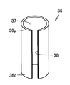
図5は、図1中のターボチャージャが備えるピン部材を示す斜視図である。図2および図5を参照して、ピン部材36は、中空部37を有する中空形状に形成されている。ピン部材36は、給油通路43に挿入される一方端36pと、給油孔21hに挿入される他方端36qとを有する。このような形状を有するピン部材36を設けることにより、中心軸101周りのフローティングベアリング21の回転が規制されている。
FIG. 5 is a perspective view showing a pin member provided in the turbocharger in FIG. 1. Referring to FIGS. 2 and 5, the
本実施の形態では、ばね鋼からなる薄板を巻回することによって、ピン部材36が形成されている。巻回された薄板の端辺の繋ぎ目には、一方端36pと他方端36qとの間で延びるスリット38が形成されている。
In the present embodiment, the
フローティングベアリング26は、中心軸101周りの回転が許容され、センターハウジング41およびタービンシャフト12から浮遊した状態でタービンシャフト12を支持するフルフローティングベアリングとして設けられている。一方、フローティングベアリング21は、中心軸101周りの回転が規制され、センターハウジング41およびタービンシャフト12から浮遊した状態でタービンシャフト12を支持するセミフローティングベアリングとして設けられている。
The floating
図2を参照して、ターボチャージャ10は、中心軸101の軸方向に沿ったフローティングベアリング21の移動を規制する第1のリング部材としてのタービン側スナップリング31と、第2のリング部材としてのコンプレッサ側スナップリング32とをさらに備える。
Referring to FIG. 2, the
タービン側スナップリング31は、フローティングベアリング21とタービン66との間に配置されている。タービン側スナップリング31は、タービン66に近接する方向のフローティングベアリング21の移動を規制している。コンプレッサ側スナップリング32は、フローティングベアリング21を挟んでタービン側スナップリング31の反対側に配置されている。コンプレッサ側スナップリング32は、コンプレッサ61に近接する方向のフローティングベアリング21の移動を規制している。
The turbine-
中心軸101の軸方向に沿ったフローティングベアリング26の移動は、スラストブッシュ63と、コンプレッサ側スナップリング32と同形状を有するスナップリング33とによって規制されている。
The movement of the floating
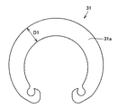
図6は、図2中の2点鎖線VIで囲まれた位置を拡大して示す断面図である。図7は、図1中のターボチャージャが備えるタービン側スナップリングを示す正面図である。図8は、図1中のターボチャージャが備えるコンプレッサ側スナップリングを示す正面図である。 6 is an enlarged cross-sectional view of a position surrounded by a two-dot chain line VI in FIG. FIG. 7 is a front view showing a turbine-side snap ring included in the turbocharger in FIG. FIG. 8 is a front view showing a compressor-side snap ring included in the turbocharger in FIG. 1.
図6から図8を参照して、センターハウジング41の内周面41bには、スナップリング溝48および49が形成されている。スナップリング溝48とスナップリング溝49とは、同じ深さを有する。タービン側スナップリング31およびコンプレッサ側スナップリング32は、それぞれ、スナップリング溝48およびスナップリング溝49に嵌め合わされている。
With reference to FIGS. 6 to 8,
タービン側スナップリング31およびコンプレッサ側スナップリング32は、それぞれ、フローティングベアリング21と当接する表面31aおよび32aを有する。中心軸101を中心とする半径方向の表面31aの幅D1は、表面32aの幅D2よりも大きい。内周面41bから突出するタービン側スナップリング31の突出長さは、コンプレッサ側スナップリング32の突出長さよりも大きい。このような構成により、フローティングベアリング21と表面31aとの接触面積が、フローティングベアリング21と表面32aとの接触面積よりも大きくなる。
The turbine-
給油通路43からフローティングベアリング21に供給されるオイルの流れについて説明する。給油通路43に流れるオイルは、中空部37を通ってフローティングベアリング21に向かう。この際、中空部37を通るオイルは、他方端36qから流出して、外周面12aと内周面21bとの間の隙間に供給される。また、中空部37を通るオイルは、ピン部材36に形成された図5中のスリット38から流出して、外周面21aと内周面41bとの間の隙間に供給される。すなわち、ピン部材36には、外周面12aと内周面21bとの間の隙間および外周面21aと内周面41bとの間の隙間の双方にオイルを供給する孔としての中空部37およびスリット38が形成されている。
The flow of oil supplied from the
外周面21aと内周面41bとの間の隙間に供給されたオイルは、フローティングベアリング21とタービン側スナップリング31との間およびフローティングベアリング21とコンプレッサ側スナップリング32との間を通って、それぞれタービン側およびコンプレッサ側に排出される。
The oil supplied to the gap between the outer
本実施の形態では、フローティングベアリング21に供給されるオイル量がフローティングベアリング26に供給されるオイル量よりも大きくなるように、給油通路43および44が形成されている。この場合、タービンシャフト12にオイルスリンガ67が成形されているにもかかわらず、センターハウジング41内からタービンハウジング71内に漏出するオイル量が増大するおそれがある。
In the present embodiment, the
これに対して、ターボチャージャ10では、フローティングベアリング21と表面31aとの接触面積が、フローティングベアリング21と表面32aとの接触面積よりも大きく設定されているため、フローティングベアリング21からタービン側に排出されるオイル量をより少なくできる。これにより、タービンハウジング71へのオイルの漏出を抑え、オイルの消費量の増大を抑制できる。
On the other hand, in the
この発明の実施の形態1におけるターボチャージャ10は、所定の軸としての中心軸101に沿って延びるシャフトとしてのタービンシャフト12と、タービンシャフト12を取り囲むように設けられたハウジングとしてのセンターハウジング41と、中心軸101方向に並ぶ第1および第2のフローティングベアリングとしてのフローティングベアリング21および26とを備える。タービンシャフト12は、中心軸101方向に離間したコンプレッサ61とタービン66とを連結する。フローティングベアリング21および26は、センターハウジング41およびタービンシャフト12の各々との間の隙間にオイルを介在させて浮遊し、センターハウジング41に対してタービンシャフト12を回転自在に支持する。フローティングベアリング21は、タービン66側に配設されている。フローティングベアリング26は、コンプレッサ61側に配設されている。
A
ターボチャージャ10は、さらに、フローティングベアリング21の中心軸101の軸周りの回転を規制する第1の回転止め部材としてのピン部材36を備える。センターハウジング41には、フローティングベアリング21に供給するオイルが流れる第1の給油通路としての給油通路43と、フローティングベアリング26に供給するオイルが流れる第2の給油通路としての給油通路44とが形成されている。給油通路43の断面積は、給油通路44の断面積よりも大きい。
The
このように構成された、この発明の実施の形態1におけるターボチャージャ10によれば、以下に説明する理由から、冷却性能の維持を図りつつ、異音の発生を十分に抑制することができる。
According to the
従来、ターボチャージャ付きのエンジンでフルフロート方式の軸受けを採用した場合、ホワール音と呼ばれる異音の発生が指摘される場合がある。このホワール音は、フルフロート方式の軸受け特有の現象であり、その発生原因は、軸受け内外に形成される油膜の自励振動に起因すると考えられる。 Conventionally, when a full float type bearing is adopted in an engine with a turbocharger, the occurrence of an abnormal noise called a whirl may be pointed out. This whirl noise is a phenomenon peculiar to a full float type bearing, and the cause of the occurrence is considered to be due to self-excited vibration of an oil film formed inside and outside the bearing.
これに対して、本実施の形態では、フローティングベアリング21の回転を規制し、セミフロート化することによって、油膜の自励振動を抑えることができる。これにより、振動特性線図やキャンベル線図上に現れるホワール振動成分を低減させ、車両のNV性能(noise and vibration)を向上させることができる。特にターボチャージャ10では、タービン66の重量がコンプレッサ61の重量よりも大きいため、コンプレッサ側よりもタービン側でホワール振動成分が大きくなる。このため、タービン側に配設されたフローティングベアリング21の回転を規制することによって、ホワール振動成分をより効果的に低減させることができる。
In contrast, in the present embodiment, the self-excited vibration of the oil film can be suppressed by regulating the rotation of the floating
一方、フローティングベアリング21をセミフロート化することによって、フローティングベアリング21における発熱量が増大する。また、フローティングベアリング21の近傍では、排気ガスの影響を大きく受けるため、温度が上昇する。これに対して、本実施の形態では、フローティングベアリング21にオイルを供給する給油通路43の断面積を、フローティングベアリング26にオイルを供給する給油通路44の断面積よりも大きく設定している。これにより、フローティングベアリング21をより積極的に冷却し、冷却性能の維持を図ることができる。
On the other hand, by making the floating
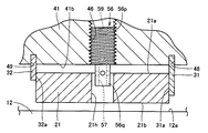
図9は、図1中のターボチャージャが備えるピン部材の第1の変形例を示す断面図である。図9を参照して、本変形例では、図7中のピン部材36に替えてピン部材51が設けられている。ピン部材51は、中空部52を有する筒形状に形成されている。ピン部材51は、給油通路43に挿入される一方端51pと、給油孔21hに挿入される他方端51qとを有する。ピン部材51には、図7中のピン部材36に形成されたスリット38の替わりに、孔54が形成されている。中空部52を通るオイルは、孔54を介して、外周面21aと内周面41bとの間の隙間に供給される。
FIG. 9 is a cross-sectional view showing a first modification of the pin member provided in the turbocharger in FIG. Referring to FIG. 9, in this modification, a
図10は、図1中のターボチャージャが備えるピン部材の第2の変形例を示す断面図である。図10を参照して、本変形例では、図7中のピン部材36に替えてピン部材56が設けられている。ピン部材56は、給油通路43とは別に、センターハウジング41に形成された雌ねじ孔46に設けられている。ピン部材56は、雌ねじ孔46に螺合される一方端56pと、給油孔21hに挿入される他方端56qとを有する。ピン部材56には、他方端51q側に開口し、外周面21aと内周面41bとの間の隙間に連通する孔57が形成されている。外周面12aと内周面21bとの間の隙間を流れるオイルは、孔57を介して、外周面21aと内周面41bとの間の隙間に供給される。
FIG. 10 is a cross-sectional view showing a second modification of the pin member provided in the turbocharger in FIG. Referring to FIG. 10, in this modification, a
これらの変形例によっても、フローティングベアリング21の内外へのオイルの供給を確保すると同時に、フローティングベアリング21の回転を規制することができる。
Also according to these modified examples, it is possible to restrict the rotation of the floating
(実施の形態2)
図11は、この発明の実施の形態2におけるターボチャージャを示す断面図である。図11は、実施の形態1における図2に対応する図である。本実施の形態におけるターボチャージャは、実施の形態1におけるターボチャージャ10と比較して、基本的には同様の構造を備える。以下、重複する構造については説明を繰り返さない。
(Embodiment 2)
FIG. 11 is a cross-sectional view showing a turbocharger according to Embodiment 2 of the present invention. FIG. 11 is a diagram corresponding to FIG. 2 in the first embodiment. The turbocharger in the present embodiment basically has the same structure as the
図11を参照して、本実施の形態では、ターボチャージャが、フローティングベアリング26の回転を規制する第2の回転止め部材としてのピン部材81をさらに備える。ピン部材81は、図5中のピン部材36と同様の形状を有する。ピン部材81に替えて、図9および図10中にそれぞれ示すピン部材51またはピン部材56を設けても良い。
Referring to FIG. 11, in the present embodiment, the turbocharger further includes a
このように構成された、この発明の実施の形態2におけるターボチャージャによれば、フローティングベアリング21に加えて、フローティングベアリング26をセミフロート化することによって、ホワール振動成分をさらに効果的に低減させることができる。なお、実施の形態1におけるターボチャージャ10では、実施の形態2におけるターボチャージャと比較して、ピン部材を設ける位置が少なくなる。このため、部品点数の増加や組み立て作業の複雑化による製造コストの増大を抑制することができる。
According to the turbocharger of the second embodiment of the present invention configured as described above, the whirl vibration component can be further effectively reduced by semi-floating the floating
今回開示された実施の形態はすべての点で例示であって制限的なものではないと考えられるべきである。本発明の範囲は上記した説明ではなくて特許請求の範囲によって示され、特許請求の範囲と均等の意味および範囲内でのすべての変更が含まれることが意図される。 The embodiment disclosed this time should be considered as illustrative in all points and not restrictive. The scope of the present invention is defined by the terms of the claims, rather than the description above, and is intended to include any modifications within the scope and meaning equivalent to the terms of the claims.
10 ターボチャージャ、12 タービンシャフト、21,26 フローティングベアリング、21h 給油孔、31 タービン側スナップリング、32 コンプレッサ側スナップリング、36,51,56,81 ピン部材、36p,51p,56p 一方端、36q,51q,56q 他方端、41 センターハウジング、43,44 給油通路、61 コンプレッサ、66 タービン、101 中心軸。 10 Turbocharger, 12 Turbine shaft, 21, 26 Floating bearing, 21h Oil supply hole, 31 Turbine side snap ring, 32 Compressor side snap ring, 36, 51, 56, 81 Pin member, 36p, 51p, 56p One end, 36q, 51q, 56q The other end, 41 Center housing, 43, 44 Oil supply passage, 61 Compressor, 66 Turbine, 101 Central axis.
Claims (5)
前記シャフトを取り囲むように設けられたハウジングと、
前記ハウジングおよび前記シャフトの各々との間の隙間にオイルを介在させて浮遊し、前記ハウジングに対して前記シャフトを回転自在に支持し、前記所定の軸方向に並ぶ第1および第2のフローティングベアリングとを備え、
前記第1のフローティングベアリングは、前記タービン側に配設され、前記第2のフローティングベアリングは、前記コンプレッサ側に配設され、さらに、
前記第1のフローティングベアリングの前記所定の軸周りの回転を規制する第1の回転止め部材を備え、
前記ハウジングには、前記第1のフローティングベアリングに供給するオイルが流れる第1の給油通路と、前記第2のフローティングベアリングに供給するオイルが流れる第2の給油通路とが形成され、前記第1の給油通路の断面積が前記第2の給油通路の断面積よりも大きい、ターボチャージャ。 A shaft extending along a predetermined axis and connecting the compressor and the turbine spaced apart in the predetermined axial direction;
A housing provided to surround the shaft;
First and second floating bearings that float with oil interposed between the housing and each of the shafts, support the shaft rotatably with respect to the housing, and are aligned in the predetermined axial direction And
The first floating bearing is disposed on the turbine side, the second floating bearing is disposed on the compressor side, and
A first anti-rotation member for restricting rotation of the first floating bearing around the predetermined axis;
The housing is formed with a first oil supply passage through which oil supplied to the first floating bearing flows and a second oil supply passage through which oil supplied to the second floating bearing flows. A turbocharger in which a cross-sectional area of the oil supply passage is larger than a cross-sectional area of the second oil supply passage.
前記第1の回転止め部材は、前記第1の給油通路に挿入される一方端と、前記給油孔に挿入される他方端とを有する円筒形状に形成されている、請求項1または2に記載のターボチャージャ。 The first floating bearing is formed with an oil supply hole penetrating in a radial direction around the predetermined axis,
The said 1st rotation stopping member is formed in the cylindrical shape which has one end inserted in the said 1st oil supply channel | path, and the other end inserted in the said oil supply hole. Turbocharger.
前記第1のリング部材は、前記第1のフローティングベアリングと前記タービンとの間に配設され、前記第2のリング部材は、前記第1のフローティングベアリングに対して前記第1のリング部材の反対側に配設され、
前記所定の軸を中心とした半径方向の前記第1のリング部材の幅は、前記第2のリング部材の幅よりも大きい、請求項1から3のいずれか1項に記載のターボチャージャ。 First and second ring members that abut against the first floating bearing and restrict the movement of the first floating bearing in the predetermined axial direction are further provided,
The first ring member is disposed between the first floating bearing and the turbine, and the second ring member is opposite to the first ring member with respect to the first floating bearing. Arranged on the side,
The turbocharger according to any one of claims 1 to 3, wherein a width of the first ring member in a radial direction around the predetermined axis is larger than a width of the second ring member.
Priority Applications (1)
| Application Number | Priority Date | Filing Date | Title |
|---|---|---|---|
| JP2006115622A JP2007285252A (en) | 2006-04-19 | 2006-04-19 | Turbo charger |
Applications Claiming Priority (1)
| Application Number | Priority Date | Filing Date | Title |
|---|---|---|---|
| JP2006115622A JP2007285252A (en) | 2006-04-19 | 2006-04-19 | Turbo charger |
Publications (1)
| Publication Number | Publication Date |
|---|---|
| JP2007285252A true JP2007285252A (en) | 2007-11-01 |
Family
ID=38757257
Family Applications (1)
| Application Number | Title | Priority Date | Filing Date |
|---|---|---|---|
| JP2006115622A Withdrawn JP2007285252A (en) | 2006-04-19 | 2006-04-19 | Turbo charger |
Country Status (1)
| Country | Link |
|---|---|
| JP (1) | JP2007285252A (en) |
Cited By (15)
| Publication number | Priority date | Publication date | Assignee | Title |
|---|---|---|---|---|
| JP2011236966A (en) * | 2010-05-10 | 2011-11-24 | Ihi Corp | Floating bushing, sliding bearing structure and supercharger |
| CN102859122A (en) * | 2010-05-14 | 2013-01-02 | 博格华纳公司 | Exhaust-gas turbocharger |
| JP2013050090A (en) * | 2011-08-31 | 2013-03-14 | Ihi Corp | Multi-sealing structure and supercharger |
| JP2013155668A (en) * | 2012-01-30 | 2013-08-15 | Daihatsu Motor Co Ltd | Turbocharger |
| JP2014047680A (en) * | 2012-08-30 | 2014-03-17 | Daihatsu Motor Co Ltd | Turbosupercharger |
| JP2015530537A (en) * | 2012-09-24 | 2015-10-15 | アイ・エイチ・アイ チャージング システムズ インターナショナル ゲーエムベーハー | Bearing device and exhaust gas turbocharger |
| US9726189B2 (en) | 2011-03-29 | 2017-08-08 | Mitsubishi Heavy Industries, Ltd. | Turbocharger and method of manufacturing floating bush |
| US9790812B2 (en) * | 2012-12-27 | 2017-10-17 | Borgwarner Inc. | Fluid film conical or hemispherical floating ring bearings |
| KR101830817B1 (en) * | 2009-05-07 | 2018-02-21 | 보르그워너 인코퍼레이티드 | Spring clip method for anti-rotation and thrust constraint of a rolling element bearing cartridge |
| JP2018505342A (en) * | 2015-02-11 | 2018-02-22 | ボーグワーナー インコーポレーテッド | Bearing for turbocharger |
| KR101838169B1 (en) * | 2009-05-07 | 2018-03-13 | 보르그워너 인코퍼레이티드 | Sliding clip method for anti-rotation and thrust constraint of a rolling element bearing cartridge |
| WO2019039338A1 (en) * | 2017-08-25 | 2019-02-28 | 株式会社Ihi | Supercharger |
| US10465747B2 (en) | 2015-07-21 | 2019-11-05 | Ihi Corporation | Bearing structure and turbocharger |
| US10526960B2 (en) | 2015-09-14 | 2020-01-07 | Mitsubishi Heavy Industries Engine & Turbocharger, Ltd. | Turbocharger |
| JP2020020266A (en) * | 2018-07-30 | 2020-02-06 | 三菱重工業株式会社 | Bearing device and turbocharger |
-
2006
- 2006-04-19 JP JP2006115622A patent/JP2007285252A/en not_active Withdrawn
Cited By (32)
| Publication number | Priority date | Publication date | Assignee | Title |
|---|---|---|---|---|
| KR101838169B1 (en) * | 2009-05-07 | 2018-03-13 | 보르그워너 인코퍼레이티드 | Sliding clip method for anti-rotation and thrust constraint of a rolling element bearing cartridge |
| KR101830817B1 (en) * | 2009-05-07 | 2018-02-21 | 보르그워너 인코퍼레이티드 | Spring clip method for anti-rotation and thrust constraint of a rolling element bearing cartridge |
| JP2011236966A (en) * | 2010-05-10 | 2011-11-24 | Ihi Corp | Floating bushing, sliding bearing structure and supercharger |
| US9638059B2 (en) * | 2010-05-14 | 2017-05-02 | Borgwarner Inc. | Exhaust-gas turbocharger |
| JP2013526672A (en) * | 2010-05-14 | 2013-06-24 | ボーグワーナー インコーポレーテッド | Exhaust gas turbocharger |
| US20130108483A1 (en) * | 2010-05-14 | 2013-05-02 | Borgwarner Inc. | Exhaust-gas turbocharger |
| KR101829362B1 (en) * | 2010-05-14 | 2018-02-19 | 보르그워너 인코퍼레이티드 | Exhaust-gas turbocharger |
| CN102859122A (en) * | 2010-05-14 | 2013-01-02 | 博格华纳公司 | Exhaust-gas turbocharger |
| US9726189B2 (en) | 2011-03-29 | 2017-08-08 | Mitsubishi Heavy Industries, Ltd. | Turbocharger and method of manufacturing floating bush |
| JP2013050090A (en) * | 2011-08-31 | 2013-03-14 | Ihi Corp | Multi-sealing structure and supercharger |
| JP2013155668A (en) * | 2012-01-30 | 2013-08-15 | Daihatsu Motor Co Ltd | Turbocharger |
| JP2014047680A (en) * | 2012-08-30 | 2014-03-17 | Daihatsu Motor Co Ltd | Turbosupercharger |
| JP2015530537A (en) * | 2012-09-24 | 2015-10-15 | アイ・エイチ・アイ チャージング システムズ インターナショナル ゲーエムベーハー | Bearing device and exhaust gas turbocharger |
| JP2016191465A (en) * | 2012-09-24 | 2016-11-10 | アイ・エイチ・アイ チャージング システムズ インターナショナル ゲーエムベーハー | Bearing device and exhaust gas turbocharger |
| US9790812B2 (en) * | 2012-12-27 | 2017-10-17 | Borgwarner Inc. | Fluid film conical or hemispherical floating ring bearings |
| EP3256707A4 (en) * | 2015-02-11 | 2018-10-17 | BorgWarner Inc. | Bearings for a turbocharger |
| JP2018505342A (en) * | 2015-02-11 | 2018-02-22 | ボーグワーナー インコーポレーテッド | Bearing for turbocharger |
| US10465747B2 (en) | 2015-07-21 | 2019-11-05 | Ihi Corporation | Bearing structure and turbocharger |
| US10526960B2 (en) | 2015-09-14 | 2020-01-07 | Mitsubishi Heavy Industries Engine & Turbocharger, Ltd. | Turbocharger |
| US10989115B2 (en) | 2017-08-25 | 2021-04-27 | Ihi Corporation | Turbocharger |
| WO2019039338A1 (en) * | 2017-08-25 | 2019-02-28 | 株式会社Ihi | Supercharger |
| CN110832181B (en) * | 2017-08-25 | 2021-09-07 | 株式会社Ihi | Pressure booster |
| CN110832181A (en) * | 2017-08-25 | 2020-02-21 | 株式会社Ihi | Pressure booster |
| JPWO2019039338A1 (en) * | 2017-08-25 | 2020-04-16 | 株式会社Ihi | Supercharger |
| JP2020020266A (en) * | 2018-07-30 | 2020-02-06 | 三菱重工業株式会社 | Bearing device and turbocharger |
| KR20210031862A (en) * | 2018-07-30 | 2021-03-23 | 미쓰비시주코마린마시나리 가부시키가이샤 | Bearing unit and turbocharger |
| CN112513440A (en) * | 2018-07-30 | 2021-03-16 | 三菱重工船用机械株式会社 | Bearing device and turbocharger |
| EP3832086A4 (en) * | 2018-07-30 | 2021-06-09 | Mitsubishi Heavy Industries Marine Machinery & Equipment Co., Ltd. | Bearing device and turbo supercharger |
| WO2020026863A1 (en) * | 2018-07-30 | 2020-02-06 | 三菱重工業株式会社 | Bearing device and turbo supercharger |
| US11415021B2 (en) | 2018-07-30 | 2022-08-16 | Mitsubishi Heavy Industries Marine Machinery & Equipment Co., Ltd. | Bearing device and turbocharger |
| KR102466046B1 (en) | 2018-07-30 | 2022-11-10 | 미쓰비시주코마린마시나리 가부시키가이샤 | Bearing device and turbocharger |
| JP7269706B2 (en) | 2018-07-30 | 2023-05-09 | 三菱重工マリンマシナリ株式会社 | Bearing device and turbocharger |
Similar Documents
| Publication | Publication Date | Title |
|---|---|---|
| JP2007285252A (en) | Turbo charger | |
| US7670056B2 (en) | Stepped outer diameter semi-floating bearing | |
| JPH0540273Y2 (en) | ||
| KR0154105B1 (en) | Turbocharger compressor wheel assembly with boreless hub compressor wheel | |
| US8857180B2 (en) | Turbocharger bearing anti-rotation plate | |
| US8061976B2 (en) | Variable geometry turbocharger, vane ring assembly with retaining member | |
| US8376695B2 (en) | Variable geometry vane ring assembly with stepped spacer | |
| KR101829362B1 (en) | Exhaust-gas turbocharger | |
| US8267647B2 (en) | Variable geometry turbocharger lower vane ring retaining system | |
| US20090110572A1 (en) | Anisotropic bearing supports for turbochargers | |
| US20070280824A1 (en) | Combination hydrodynamic and rolling bearing system | |
| JP2011153668A (en) | Bearing device | |
| WO2012036122A1 (en) | Fixed vane-type turbo charger | |
| JP2007046642A (en) | Supercharger and fully floating bearing | |
| JP6562150B2 (en) | Turbocharger | |
| US20020073714A1 (en) | Gas turbine engine with offset shroud | |
| JP2010138753A (en) | Bearing device for supercharger | |
| KR20170017764A (en) | Turbocharger assembly | |
| JP4386563B2 (en) | Turbocharger bearing device | |
| JP2013130136A (en) | Fastening part structure of turbocharger | |
| JP4238610B2 (en) | Turbocharger seal structure | |
| JP4239536B2 (en) | Bearing device for turbocharger | |
| KR102646973B1 (en) | Bearing structure, supercharger equipped with the same, and method of assembling the supercharger | |
| JP2007205179A (en) | Turbocharger | |
| JP5995735B2 (en) | Turbocharger bearing structure and turbocharger including the same |
Legal Events
| Date | Code | Title | Description |
|---|---|---|---|
| A300 | Withdrawal of application because of no request for examination |
Free format text: JAPANESE INTERMEDIATE CODE: A300 Effective date: 20090707 |