EP1273765B1 - Turbocharger shaft dual phase seal - Google Patents
Turbocharger shaft dual phase seal Download PDFInfo
- Publication number
- EP1273765B1 EP1273765B1 EP01116392A EP01116392A EP1273765B1 EP 1273765 B1 EP1273765 B1 EP 1273765B1 EP 01116392 A EP01116392 A EP 01116392A EP 01116392 A EP01116392 A EP 01116392A EP 1273765 B1 EP1273765 B1 EP 1273765B1
- Authority
- EP
- European Patent Office
- Prior art keywords
- seal
- rotor
- dual phase
- wheel
- grooving
- Prior art date
- Legal status (The legal status is an assumption and is not a legal conclusion. Google has not performed a legal analysis and makes no representation as to the accuracy of the status listed.)
- Expired - Lifetime
Links
Images


Classifications
-
- F—MECHANICAL ENGINEERING; LIGHTING; HEATING; WEAPONS; BLASTING
- F01—MACHINES OR ENGINES IN GENERAL; ENGINE PLANTS IN GENERAL; STEAM ENGINES
- F01D—NON-POSITIVE DISPLACEMENT MACHINES OR ENGINES, e.g. STEAM TURBINES
- F01D25/00—Component parts, details, or accessories, not provided for in, or of interest apart from, other groups
- F01D25/18—Lubricating arrangements
- F01D25/183—Sealing means
- F01D25/186—Sealing means for sliding contact bearing
-
- F—MECHANICAL ENGINEERING; LIGHTING; HEATING; WEAPONS; BLASTING
- F01—MACHINES OR ENGINES IN GENERAL; ENGINE PLANTS IN GENERAL; STEAM ENGINES
- F01D—NON-POSITIVE DISPLACEMENT MACHINES OR ENGINES, e.g. STEAM TURBINES
- F01D11/00—Preventing or minimising internal leakage of working-fluid, e.g. between stages
- F01D11/02—Preventing or minimising internal leakage of working-fluid, e.g. between stages by non-contact sealings, e.g. of labyrinth type
- F01D11/04—Preventing or minimising internal leakage of working-fluid, e.g. between stages by non-contact sealings, e.g. of labyrinth type using sealing fluid, e.g. steam
-
- F—MECHANICAL ENGINEERING; LIGHTING; HEATING; WEAPONS; BLASTING
- F01—MACHINES OR ENGINES IN GENERAL; ENGINE PLANTS IN GENERAL; STEAM ENGINES
- F01D—NON-POSITIVE DISPLACEMENT MACHINES OR ENGINES, e.g. STEAM TURBINES
- F01D25/00—Component parts, details, or accessories, not provided for in, or of interest apart from, other groups
- F01D25/18—Lubricating arrangements
- F01D25/183—Sealing means
-
- F—MECHANICAL ENGINEERING; LIGHTING; HEATING; WEAPONS; BLASTING
- F02—COMBUSTION ENGINES; HOT-GAS OR COMBUSTION-PRODUCT ENGINE PLANTS
- F02C—GAS-TURBINE PLANTS; AIR INTAKES FOR JET-PROPULSION PLANTS; CONTROLLING FUEL SUPPLY IN AIR-BREATHING JET-PROPULSION PLANTS
- F02C7/00—Features, components parts, details or accessories, not provided for in, or of interest apart form groups F02C1/00 - F02C6/00; Air intakes for jet-propulsion plants
- F02C7/06—Arrangements of bearings; Lubricating
-
- F—MECHANICAL ENGINEERING; LIGHTING; HEATING; WEAPONS; BLASTING
- F04—POSITIVE - DISPLACEMENT MACHINES FOR LIQUIDS; PUMPS FOR LIQUIDS OR ELASTIC FLUIDS
- F04D—NON-POSITIVE-DISPLACEMENT PUMPS
- F04D25/00—Pumping installations or systems
- F04D25/02—Units comprising pumps and their driving means
- F04D25/04—Units comprising pumps and their driving means the pump being fluid-driven
-
- F—MECHANICAL ENGINEERING; LIGHTING; HEATING; WEAPONS; BLASTING
- F04—POSITIVE - DISPLACEMENT MACHINES FOR LIQUIDS; PUMPS FOR LIQUIDS OR ELASTIC FLUIDS
- F04D—NON-POSITIVE-DISPLACEMENT PUMPS
- F04D29/00—Details, component parts, or accessories
- F04D29/08—Sealings
- F04D29/10—Shaft sealings
- F04D29/102—Shaft sealings especially adapted for elastic fluid pumps
-
- F—MECHANICAL ENGINEERING; LIGHTING; HEATING; WEAPONS; BLASTING
- F04—POSITIVE - DISPLACEMENT MACHINES FOR LIQUIDS; PUMPS FOR LIQUIDS OR ELASTIC FLUIDS
- F04D—NON-POSITIVE-DISPLACEMENT PUMPS
- F04D29/00—Details, component parts, or accessories
- F04D29/26—Rotors specially for elastic fluids
- F04D29/266—Rotors specially for elastic fluids mounting compressor rotors on shafts
-
- F—MECHANICAL ENGINEERING; LIGHTING; HEATING; WEAPONS; BLASTING
- F05—INDEXING SCHEMES RELATING TO ENGINES OR PUMPS IN VARIOUS SUBCLASSES OF CLASSES F01-F04
- F05D—INDEXING SCHEME FOR ASPECTS RELATING TO NON-POSITIVE-DISPLACEMENT MACHINES OR ENGINES, GAS-TURBINES OR JET-PROPULSION PLANTS
- F05D2220/00—Application
- F05D2220/40—Application in turbochargers
Definitions
- This invention relates to compressor and turbine wheel shaft seals, particularly for use in engine turbochargers and the like. More particularly, the invention relates to a shaft seal system especially applicable to four cycle engine turbochargers.
- turbocharger uses a mechanical drive train to drive a turbine/compressor rotor to provide adequate scavenging and charging air pressure at engine idle and in the lower speed and power settings of the associated engine.
- the turbocharger is provided with turbine and compressor rotor shaft seals employing labyrinth seal grooves fed with pressure air from the output of the compressor wheel.
- the developed labyrinth seal system has proved to be extremely reliable and functionally effective, as well as cost effective for use in two cycle engine applications.
- the labyrinth seal grooves are preferably formed in an inner cylinder surrounding the rotor shaft, although they could alternatively be formed in an outer cylinder rotating with the shaft.
- the labyrinth seal system used in the two cycle engine turbocharger has been found to be less effective. This is because, at idle and in operation at light loads, the four cycle turbocharger does not provide sufficient air pressure boost to supply adequate air pressure to the labyrinth seals. A suitable cost effective and reliable seal system was therefore desired to effectively limit oil leakage under the full operating range of the four cycle engine and turbocharger.
- US-A-5 066 192 discloses a dual phase seal according to the preamble of claim 1.
- DE-U-1 995 814 discloses a seal element for sealing a shaft against the loss of lubricant.
- the present invention provides an improved seal system including a dual phase seal for limiting leakage from lubricated rotor support bearings to a turbine and/or compressor wheel of a rotor operational over an extended speed range.
- the dual phase seal combines features of the previously developed labyrinth seal, effective in a higher portion of the turbocharger rotor speed range, with added features of a known auger seal, found to be effective in a lower portion of the rotor speed range.
- the dual phase seal includes an outer cylinder on the rotor between a bearing and an associated wheel, an inner cylinder carried by a rotor support and surrounding the outer cylinder with close clearance, auger seal grooving formed in one of the cylinders on a portion thereof toward the bearing, labyrinth seal grooving formed in one of the cylinders on a portion thereof toward the wheel, and a pressure air supply to the labyrinth seal at a pressure which is reduced at rotor speeds in a lower portion of the speed range.
- the seal system for a turbocharger includes a pressure air supply from an output of the compressor wheel to the labyrinth seal grooving of bearing seals for both the turbine and compressor ends of the rotor shaft.
- the auger groove portions of the dual phase seals provide effective sealing at lower rotor speeds but lose effectiveness at higher speeds.
- the labyrinth groove portions of the seals provide effective sealing at the higher rotor speeds where the auger seal portions are less effective.
- Turbocharger 10 generally indicates an exhaust driven turbocharger for an engine, such as a diesel engine intended for use in railway locomotives or other applications of medium speed diesel engines.
- Turbocharger 10 includes a rotor 12 carried by a rotor support 14 for rotation on a longitudinal axis 16 and including a turbine wheel 18 and a compressor wheel 20.
- the compressor wheel is enclosed by a compressor housing assembly 22 including components which are supported on an axially facing first side 24 of the rotor support 14.
- An exhaust duct 26 has a compressor end 28 that is mounted on a second side 30 of the rotor support 14 spaced axially from the first side 24.
- the exhaust duct 26 is physically positioned between the rotor support 14 and the turbine wheel 18 to receive exhaust gases passing through the turbine wheel and carry them to an exhaust outlet 32.
- a turbine end 34 of the exhaust duct 26 and an associated nozzle retainer assembly 35 are separately supported by an exhaust duct support 36 that is connected with the exhaust duct 26 at the turbine end 34.
- the exhaust duct support 36 also supports a turbine inlet scroll 38 which receives exhaust gas from the associated engine and directs it through a nozzle ring 40 to the turbine wheel 18 for transferring energy to drive the turbocharger compressor wheel 20.
- the rotor support 14 includes a pair of laterally spaced mounting feet 42 which are rigidly connected to an upstanding mounting portion 44 of the rotor support 14 and are adapted to be mounted on a rigid base, not shown.
- the rotor support 14 further includes a tapering rotor support portion 46 having bearings 48, 50 that rotatably support the rotor 12.
- Bearing 48 is a combination sleeve and thrust bearing while bearing 50 is primarily a sleeve bearing.
- the rotor 12 includes a shaft 52 connected with the turbine wheel 18 at one end and the compressor wheel 20 at the opposite end.
- the shaft 52 includes a pair of axially spaced bearing journals 54, 56 respectively adjacent the compressor and turbine wheel ends of the shaft.
- a flange, inboard of journal 54, carries a radial thrust reaction surface 58.
- a second flange adjacent journal 56 carries a radial surface 60.
- Journals 54, 56 are respectively supported in bearings 48, 50.
- Radial surface 58 carries thrust forces to the sleeve/thrust bearing 58 and radial surface 60 limits axial movement of the rotor.
- Connecting means of any suitable type may be provided for aligning and connecting the compressor and turbine wheels on their respective ends of the shaft 52.
- the aluminum alloy compressor wheel 20 includes an axially aligned cylindrical stub 62 on which is fixed an adapter 64 including an outer seal surface 65.
- the connecting means comprise a pair of non-locking cones including an external cone 66 extending axially from the adapter 64 and engaging an internal cone 68 formed in the compressor end of the shaft 52.
- the connecting means include non-locking cones including an external cone 70 integral with and extending axially from the turbine wheel to engagement with an internal cone 72 formed in the turbine end of the shaft 52.
- a seal collar 74 fixed on the turbine wheel adjacent the cone 70 includes an outer seal surface 76.
- the rotor elements are secured together by fastener means including a nut 78 and a long stud 79 that extends through the compressor wheel 20 and shaft 52 to engage a threaded opening 80 in the external cone 70 of the turbine wheel 18.
- the stud and nut hold the non-locking cones in engagement to maintain the compressor and turbine wheels in axial alignment on the shaft 52.
- Mechanical stops 84, 86 are preferably provided between the shaft and wheel elements of the rotor to provide angular orientation and allow reassembly of the elements in predetermined angular relation. Any suitable forms of stops may be used.
- the outer seal surface 65 of adapter 64 is an outer cylinder located between the compressor wheel 20 and bearing journal 54, which is supported by oil lubricated bearing 48 ( FIG. 1 ).
- the outer cylinder 65 is surrounded by an inner cylinder 88, formed by a bore in a compressor seal 90 fixed to the rotor support 14 at the compressor end of the support portion 46.
- the outer seal surface 76 of seal collar 74 is an outer cylinder located between the turbine wheel 18 and bearing journal 56, which is supported by oil lubricated bearing 50.
- the outer cylinder 76 is surrounded by an inner cylinder 92, formed by a bore in a turbine seal 94 fixed to the rotor support 14 at the compressor end of the support portion 46.
- the outer cylinders 65, 76 are centered within the inner cylinders 88, 92 with a predetermined close clearance selected to enhance sealing action of the dual phase seals partially defined by opposing cylinders 65, 88 and 76, 92.
- the outer cylinders 65, 76 are each provided with auger seal grooving 96 consisting of a multi-start helical thread cut into the outer cylinders 65, 76.
- the threads extend over about the inner halves of the respective outer cylinders, that is, the ends toward their adjacent bearings, and lie opposite smooth bore portions 98 of the associated inner cylinders 88, 92 ( FIGS. 3 and 4 ).
- the threads have helix angles turning in opposite directions, chosen so that rotation of the rotor causes a viscous pumping action of the threads against the smooth bores 98 that forces oil entering the clearance back toward the associated bearings.
- the inner cylinders 88, 92 are each provided with labyrinth seal grooving 100 ( FIGS 3 and 4 ) consisting of spaced circumferential lands and grooves cut into the inner cylinders 88, 92.
- the labyrinth seal grooving 100 extends over about the outer halves of the respective inner cylinders, that is, the ends toward their adjacent wheels 20, 18, and lies opposite smooth surfaced portions 102 of the associated outer cylinders 65, 76.
- a wider central groove in the grooving 100 receives air pressure through passages 104, 106 in the compressor seal 90 and passages 108, 110 in the turbine seal 94. The air pressure is received from an annular groove 112 in the turbocharger rotor support mounting portion 44 ( FIG.
- Air pressure is received at the groove 112 from the air output at the circumference of the compressor wheel and is conducted through internal passages in the rotor support 12 to the passages 106, 110 of the compressor and turbine seals 90, 94 for delivery to the labyrinth seal grooving 100.
- the air pressure in grooving 100 is distributed across the clearance from the smooth surfaced portions 102 of the outer cylinders 65, 76 and partially flows back through the clearance toward the adjacent bearings 48, 50, further preventing the passage of oil through the clearance toward the compressor and turbine wheels.
- the turbocharger rotor operates over a relatively large speed range, in which it is beyond the ability of the auger seal grooving to be fully effective.
- the auger seal portion is made to provide effective oil sealing primarily in the lower portion of the rotor operating speed range and its effectiveness drops off in the higher portion of the speed range.
- the air pressure fed to the annular groove 112 from the compressor wheel output is relatively low at low rotor speeds and inadequate to provide effective labyrinth oil sealing.
- the air pressure is adequate to provide effective sealing by the labyrinth seal portions.
- the combined auger seal grooving 96 and labyrinth seal grooving 100 together with pressure air supply thereto at higher turbine speeds comprise dual phase seals 116, 118 that provide effective oil sealing over the entire operating speed range of the turbocharger rotor 12.
- the dual phase seals comprise part of a seal system 120 that supplies pressure air to the labyrinth seals from the output of the compressor wheel, wherein the pressure is reduced in a lower portion of the rotor speed range. In this lower speed portion, the auger seal grooves are fully effective to prevent oil leakage toward the wheels.
- the dual phase seal system provides a cost effective as well as functionally effective and reliable seal system for a turbocharger or other rotary machine wherein a variable air pressure source is available.
Description
- This invention relates to compressor and turbine wheel shaft seals, particularly for use in engine turbochargers and the like. More particularly, the invention relates to a shaft seal system especially applicable to four cycle engine turbochargers.
- Well known turbocharged two cycle diesel engines have been used in railway locomotives and other applications for many years. Because two cycle engines are not self scavenged, a turbocharger has been developed which uses a mechanical drive train to drive a turbine/compressor rotor to provide adequate scavenging and charging air pressure at engine idle and in the lower speed and power settings of the associated engine. The turbocharger is provided with turbine and compressor rotor shaft seals employing labyrinth seal grooves fed with pressure air from the output of the compressor wheel. The developed labyrinth seal system has proved to be extremely reliable and functionally effective, as well as cost effective for use in two cycle engine applications. The labyrinth seal grooves are preferably formed in an inner cylinder surrounding the rotor shaft, although they could alternatively be formed in an outer cylinder rotating with the shaft.
- In designing a turbocharger for a four cycle diesel locomotive engine, the labyrinth seal system used in the two cycle engine turbocharger has been found to be less effective. This is because, at idle and in operation at light loads, the four cycle turbocharger does not provide sufficient air pressure boost to supply adequate air pressure to the labyrinth seals. A suitable cost effective and reliable seal system was therefore desired to effectively limit oil leakage under the full operating range of the four cycle engine and turbocharger.
-
US-A-5 066 192 discloses a dual phase seal according to the preamble ofclaim 1. -
DE-U-1 995 814 discloses a seal element for sealing a shaft against the loss of lubricant. - The present invention provides an improved seal system including a dual phase seal for limiting leakage from lubricated rotor support bearings to a turbine and/or compressor wheel of a rotor operational over an extended speed range. The dual phase seal combines features of the previously developed labyrinth seal, effective in a higher portion of the turbocharger rotor speed range, with added features of a known auger seal, found to be effective in a lower portion of the rotor speed range.
- In general, the dual phase seal includes an outer cylinder on the rotor between a bearing and an associated wheel, an inner cylinder carried by a rotor support and surrounding the outer cylinder with close clearance, auger seal grooving formed in one of the cylinders on a portion thereof toward the bearing, labyrinth seal grooving formed in one of the cylinders on a portion thereof toward the wheel, and a pressure air supply to the labyrinth seal at a pressure which is reduced at rotor speeds in a lower portion of the speed range.
- The seal system for a turbocharger includes a pressure air supply from an output of the compressor wheel to the labyrinth seal grooving of bearing seals for both the turbine and compressor ends of the rotor shaft. The auger groove portions of the dual phase seals provide effective sealing at lower rotor speeds but lose effectiveness at higher speeds. The labyrinth groove portions of the seals provide effective sealing at the higher rotor speeds where the auger seal portions are less effective.
- These and other features and advantages of the invention will be more fully understood from the following description of certain specific embodiments of the invention taken together with the accompanying drawings.
- In the drawings:
-
FIG. 1 is a cross-sectional view of an engine turbocharger having dual phase rotor seals in accordance with the invention; -
FIG. 2 is a side view of the rotor from the embodiment ofFIG. 1 showing seal surfaces of the adapter and seal collar; -
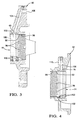
FIG. 3 is a cross-sectional view of the compressor seal assembly with portions of the adapter broken away to show the seal bore grooves; and -
FIG. 4 is a cross-sectional view of the turbine seal assembly with portions of the seal collar broken away to show the seal bore grooves. - Referring now to the drawings in detail,
numeral 10 generally indicates an exhaust driven turbocharger for an engine, such as a diesel engine intended for use in railway locomotives or other applications of medium speed diesel engines.Turbocharger 10 includes arotor 12 carried by arotor support 14 for rotation on alongitudinal axis 16 and including aturbine wheel 18 and acompressor wheel 20. The compressor wheel is enclosed by acompressor housing assembly 22 including components which are supported on an axially facingfirst side 24 of therotor support 14. Anexhaust duct 26 has acompressor end 28 that is mounted on asecond side 30 of the rotor support 14 spaced axially from thefirst side 24. - The
exhaust duct 26 is physically positioned between therotor support 14 and theturbine wheel 18 to receive exhaust gases passing through the turbine wheel and carry them to anexhaust outlet 32. Aturbine end 34 of theexhaust duct 26 and an associatednozzle retainer assembly 35 are separately supported by anexhaust duct support 36 that is connected with theexhaust duct 26 at theturbine end 34. Theexhaust duct support 36 also supports aturbine inlet scroll 38 which receives exhaust gas from the associated engine and directs it through anozzle ring 40 to theturbine wheel 18 for transferring energy to drive theturbocharger compressor wheel 20. - The
rotor support 14 includes a pair of laterally spacedmounting feet 42 which are rigidly connected to anupstanding mounting portion 44 of therotor support 14 and are adapted to be mounted on a rigid base, not shown. Therotor support 14 further includes a taperingrotor support portion 46 havingbearings rotor 12.Bearing 48 is a combination sleeve and thrust bearing while bearing 50 is primarily a sleeve bearing. - Referring particularly to
FIG. 2 , therotor 12 includes ashaft 52 connected with theturbine wheel 18 at one end and thecompressor wheel 20 at the opposite end. Theshaft 52 includes a pair of axially spaced bearingjournals journal 54, carries a radialthrust reaction surface 58. A second flangeadjacent journal 56 carries aradial surface 60.Journals bearings Radial surface 58 carries thrust forces to the sleeve/thrust bearing 58 andradial surface 60 limits axial movement of the rotor. - Connecting means of any suitable type may be provided for aligning and connecting the compressor and turbine wheels on their respective ends of the
shaft 52. The aluminumalloy compressor wheel 20 includes an axially alignedcylindrical stub 62 on which is fixed anadapter 64 including anouter seal surface 65. For thecompressor wheel 18, the connecting means comprise a pair of non-locking cones including anexternal cone 66 extending axially from theadapter 64 and engaging aninternal cone 68 formed in the compressor end of theshaft 52. - For the
turbine wheel 18, the connecting means include non-locking cones including anexternal cone 70 integral with and extending axially from the turbine wheel to engagement with aninternal cone 72 formed in the turbine end of theshaft 52. Aseal collar 74 fixed on the turbine wheel adjacent thecone 70 includes anouter seal surface 76. The rotor elements are secured together by fastener means including anut 78 and along stud 79 that extends through thecompressor wheel 20 andshaft 52 to engage a threadedopening 80 in theexternal cone 70 of theturbine wheel 18. The stud and nut hold the non-locking cones in engagement to maintain the compressor and turbine wheels in axial alignment on theshaft 52.Mechanical stops - In accordance with the invention, as best shown in
FIGS. 2-4 , theouter seal surface 65 ofadapter 64 is an outer cylinder located between thecompressor wheel 20 and bearingjournal 54, which is supported by oil lubricated bearing 48 (FIG. 1 ). Theouter cylinder 65 is surrounded by aninner cylinder 88, formed by a bore in acompressor seal 90 fixed to therotor support 14 at the compressor end of thesupport portion 46. Similarly, theouter seal surface 76 ofseal collar 74 is an outer cylinder located between theturbine wheel 18 and bearingjournal 56, which is supported by oil lubricatedbearing 50. Theouter cylinder 76 is surrounded by aninner cylinder 92, formed by a bore in aturbine seal 94 fixed to therotor support 14 at the compressor end of thesupport portion 46. Theouter cylinders inner cylinders opposing cylinders - The
outer cylinders auger seal grooving 96 consisting of a multi-start helical thread cut into theouter cylinders portions 98 of the associatedinner cylinders 88, 92 (FIGS. 3 and 4 ). The threads have helix angles turning in opposite directions, chosen so that rotation of the rotor causes a viscous pumping action of the threads against thesmooth bores 98 that forces oil entering the clearance back toward the associated bearings. - The
inner cylinders FIGS 3 and 4 ) consisting of spaced circumferential lands and grooves cut into theinner cylinders adjacent wheels portions 102 of the associatedouter cylinders grooving 100 receives air pressure throughpassages compressor seal 90 andpassages turbine seal 94. The air pressure is received from anannular groove 112 in the turbocharger rotor support mounting portion 44 (FIG. 1 ) behind theback face 114 of the compressor wheel near its outer periphery. Air pressure is received at thegroove 112 from the air output at the circumference of the compressor wheel and is conducted through internal passages in therotor support 12 to thepassages portions 102 of theouter cylinders adjacent bearings - The turbocharger rotor operates over a relatively large speed range, in which it is beyond the ability of the auger seal grooving to be fully effective. Thus, the auger seal portion is made to provide effective oil sealing primarily in the lower portion of the rotor operating speed range and its effectiveness drops off in the higher portion of the speed range. Conversely, the air pressure fed to the
annular groove 112 from the compressor wheel output is relatively low at low rotor speeds and inadequate to provide effective labyrinth oil sealing. However, in the higher portion of the rotor speed range the air pressure is adequate to provide effective sealing by the labyrinth seal portions. - Thus the combined auger seal grooving 96 and labyrinth seal grooving 100 together with pressure air supply thereto at higher turbine speeds comprise dual phase seals 116, 118 that provide effective oil sealing over the entire operating speed range of the
turbocharger rotor 12. In the turbocharger application, the dual phase seals comprise part of aseal system 120 that supplies pressure air to the labyrinth seals from the output of the compressor wheel, wherein the pressure is reduced in a lower portion of the rotor speed range. In this lower speed portion, the auger seal grooves are fully effective to prevent oil leakage toward the wheels. At higher rotor speeds, higher air pressures supplied by the compressor wheel make the labyrinth seal portions fully effective to prevent oil leakage while the effectiveness of the auger seal portions is reduced. Since positive clearance is provided between the inner and outer cylinders of the dual phase seals, virtually no wear is experienced at the seal surfaces during operation of the turbocharger. Further, if some contact did occur, only minor wear would be experienced which would not impair the sealing functions. Additionally, the dual seal assembly includes no fragile components which can break and potentially damage the rotor. Thus the dual phase seal system provides a cost effective as well as functionally effective and reliable seal system for a turbocharger or other rotary machine wherein a variable air pressure source is available. - While the invention has been described by reference to certain preferred embodiments, it should be understood that numerous changes could be made within the spirit and scope of the inventive concepts described. Accordingly, it is intended that the invention not be limited to the disclosed embodiments, but that it have the full scope permitted by the language of the following claims.
Claims (6)
- A dual phase seal for limiting oil leakage from a lubricated bearing of a rotor support (14) to a gas reacting wheel of a rotor (12) operational over an extended speed range, said seal comprising:an outer cylinder (65) on the rotor between the bearing and the wheel;an inner cylinder (88) carried by the rotor support and surrounding the outer cylinder with close clearance;auger seal grooving (96) formed in one of the cylinders on a portion thereof toward the bearing; characterized by :labyrinth seal grooving (100) formed in one of the cylinders on a portion thereof toward the wheel; andpressure air supply for supplying air to the labyrinth seal grooving (100) at a pressure which is reduced at rotor speeds in a lower portion of the rotor speed range.
- A dual phase seal as in claim 1 wherein said wheel is an air compressing impeller.
- A dual phase seal as in claim 1 wherein said wheel is an exhaust gas driven turbine.
- A dual phase seal as in claim 1 wherein said air supply is an output of an air compressing impeller mounted on said rotor (12).
- A dual phase seal as in claim 1 wherein said auger seal grooving (96) is in the outer cylinder (65).
- A dual phase seal as in claim 1 wherein said labyrinth seal grooving (100) is in the inner cylinder (88).
Priority Applications (4)
| Application Number | Priority Date | Filing Date | Title |
|---|---|---|---|
| US09/567,877 US6368077B1 (en) | 2000-05-10 | 2000-05-10 | Turbocharger shaft dual phase seal |
| CA002352021A CA2352021C (en) | 2000-05-10 | 2001-07-03 | Turbocharger shaft dual phase seal |
| DE60139928T DE60139928D1 (en) | 2001-07-06 | 2001-07-06 | Two-phase seal for a turbocharger |
| EP01116392A EP1273765B1 (en) | 2000-05-10 | 2001-07-06 | Turbocharger shaft dual phase seal |
Applications Claiming Priority (3)
| Application Number | Priority Date | Filing Date | Title |
|---|---|---|---|
| US09/567,877 US6368077B1 (en) | 2000-05-10 | 2000-05-10 | Turbocharger shaft dual phase seal |
| CA002352021A CA2352021C (en) | 2000-05-10 | 2001-07-03 | Turbocharger shaft dual phase seal |
| EP01116392A EP1273765B1 (en) | 2000-05-10 | 2001-07-06 | Turbocharger shaft dual phase seal |
Publications (2)
| Publication Number | Publication Date |
|---|---|
| EP1273765A1 EP1273765A1 (en) | 2003-01-08 |
| EP1273765B1 true EP1273765B1 (en) | 2009-09-16 |
Family
ID=27171575
Family Applications (1)
| Application Number | Title | Priority Date | Filing Date |
|---|---|---|---|
| EP01116392A Expired - Lifetime EP1273765B1 (en) | 2000-05-10 | 2001-07-06 | Turbocharger shaft dual phase seal |
Country Status (3)
| Country | Link |
|---|---|
| US (1) | US6368077B1 (en) |
| EP (1) | EP1273765B1 (en) |
| CA (1) | CA2352021C (en) |
Cited By (3)
| Publication number | Priority date | Publication date | Assignee | Title |
|---|---|---|---|---|
| WO2013126232A1 (en) * | 2012-02-20 | 2013-08-29 | Borgwarner Inc. | Fluid cooled electrically-assisted turbocharger |
| US9470231B2 (en) | 2012-01-06 | 2016-10-18 | Borgwarner Inc. | Electrically assisted turbocharger |
| US10670029B2 (en) | 2012-02-17 | 2020-06-02 | Borgwarner Inc. | Multi-segment turbocharger bearing housing and methods therefor |
Families Citing this family (39)
| Publication number | Priority date | Publication date | Assignee | Title |
|---|---|---|---|---|
| US6499969B1 (en) * | 2000-05-10 | 2002-12-31 | General Motors Corporation | Conically jointed turbocharger rotor |
| US6966746B2 (en) * | 2002-12-19 | 2005-11-22 | Honeywell International Inc. | Bearing pressure balance apparatus |
| WO2004063535A1 (en) * | 2003-01-10 | 2004-07-29 | Honeywell International Inc. | Sealing means for a lubrication system in a turbocharger |
| EP1766195B1 (en) * | 2004-07-09 | 2010-08-25 | Honeywell International Inc. | Turbocharger housing, turbocharger and a multiturbocharger system |
| US20100253005A1 (en) * | 2009-04-03 | 2010-10-07 | Liarakos Nicholas P | Seal for oil-free rotary displacement compressor |
| US9068571B2 (en) * | 2009-04-03 | 2015-06-30 | Ergoseal, Inc. | Seal for oil-free rotary displacement compressor |
| EP2336571A1 (en) | 2009-12-15 | 2011-06-22 | Perkins Engines Company Limited | System for reducing compressor oil consumption |
| DE102010043198B4 (en) * | 2010-11-01 | 2022-06-02 | Abb Schweiz Ag | Burst protection for an exhaust gas turbocharger |
| DE102011001530A1 (en) * | 2011-03-24 | 2012-09-27 | Atlas Copco Energas Gmbh | turbomachinery |
| US8701477B2 (en) | 2011-09-16 | 2014-04-22 | General Electric Company | Methods and systems for diagnosing a turbocharger |
| US8850878B2 (en) | 2011-09-16 | 2014-10-07 | General Electric Company | Methods and systems for diagnosing a turbocharger |
| ITCO20120019A1 (en) * | 2012-04-27 | 2013-10-28 | Nuovo Pignone Srl | LABYRINTH HIGHLY DAMPENED SEALS WITH HELICOIDAL AND CYLINDRICAL-MIXED SHAPE |
| WO2014046909A1 (en) * | 2012-09-18 | 2014-03-27 | Borgwarner Inc. | Turbocharger shaft seal |
| GB201220300D0 (en) * | 2012-11-12 | 2012-12-26 | Cummins Ltd | Turbomachine bearing assembly preloading arrangement |
| WO2015181326A1 (en) | 2014-05-30 | 2015-12-03 | Nuovo Pignone Srl | Sealing device for turbomachines |
| US9574965B2 (en) | 2014-06-24 | 2017-02-21 | General Electric Company | System and method of determining bearing health in a rotating machine |
| US9803493B2 (en) * | 2014-10-01 | 2017-10-31 | Electro-Motive Diesel, Inc. | Turbine bearing and seal assembly for a turbocharger |
| US9188133B1 (en) | 2015-01-09 | 2015-11-17 | Borgwarner Inc. | Turbocharger compressor active diffuser |
| US9650913B2 (en) | 2015-03-09 | 2017-05-16 | Caterpillar Inc. | Turbocharger turbine containment structure |
| US9810238B2 (en) | 2015-03-09 | 2017-11-07 | Caterpillar Inc. | Turbocharger with turbine shroud |
| US9638138B2 (en) | 2015-03-09 | 2017-05-02 | Caterpillar Inc. | Turbocharger and method |
| US9732633B2 (en) | 2015-03-09 | 2017-08-15 | Caterpillar Inc. | Turbocharger turbine assembly |
| US9683520B2 (en) | 2015-03-09 | 2017-06-20 | Caterpillar Inc. | Turbocharger and method |
| US9752536B2 (en) | 2015-03-09 | 2017-09-05 | Caterpillar Inc. | Turbocharger and method |
| US10006341B2 (en) | 2015-03-09 | 2018-06-26 | Caterpillar Inc. | Compressor assembly having a diffuser ring with tabs |
| US9890788B2 (en) | 2015-03-09 | 2018-02-13 | Caterpillar Inc. | Turbocharger and method |
| US9777747B2 (en) | 2015-03-09 | 2017-10-03 | Caterpillar Inc. | Turbocharger with dual-use mounting holes |
| US9822700B2 (en) | 2015-03-09 | 2017-11-21 | Caterpillar Inc. | Turbocharger with oil containment arrangement |
| US9739238B2 (en) | 2015-03-09 | 2017-08-22 | Caterpillar Inc. | Turbocharger and method |
| US10066639B2 (en) | 2015-03-09 | 2018-09-04 | Caterpillar Inc. | Compressor assembly having a vaneless space |
| US9915172B2 (en) | 2015-03-09 | 2018-03-13 | Caterpillar Inc. | Turbocharger with bearing piloted compressor wheel |
| US9879594B2 (en) | 2015-03-09 | 2018-01-30 | Caterpillar Inc. | Turbocharger turbine nozzle and containment structure |
| US9903225B2 (en) | 2015-03-09 | 2018-02-27 | Caterpillar Inc. | Turbocharger with low carbon steel shaft |
| JP6566043B2 (en) * | 2015-12-01 | 2019-08-28 | 株式会社Ihi | Mounting structure and turbocharger |
| CN105673193B (en) * | 2016-02-22 | 2018-10-26 | 奇瑞汽车股份有限公司 | A kind of turbocharger and its lubricating method improving lubrication pressure |
| CN112119221A (en) * | 2018-05-15 | 2020-12-22 | Lg电子株式会社 | Turbo compressor |
| EP3693561A1 (en) * | 2019-02-06 | 2020-08-12 | ABB Turbo Systems AG | Shaft seal system, turbomachine with shaft seal system, and method of sealing a shaft |
| US11879348B2 (en) * | 2021-11-11 | 2024-01-23 | Progress Rail Locomotive Inc. | Bearing carrier |
| US11614001B1 (en) * | 2021-11-11 | 2023-03-28 | Progress Rail Locomotive Inc. | Turbine containment |
Family Cites Families (10)
| Publication number | Priority date | Publication date | Assignee | Title |
|---|---|---|---|---|
| DE1995814U (en) | 1968-08-19 | 1968-10-31 | Drabert Soehne | SEALING MEMBER FOR SEALING A SHAFT AGAINST LUBRICANT LEAKS. |
| US3874677A (en) * | 1973-07-19 | 1975-04-01 | Nasa | High speed, self-acting shaft seal |
| US4207035A (en) * | 1977-12-27 | 1980-06-10 | Cummins Engine Company, Inc. | Turbocharger assembly |
| US4257617A (en) * | 1978-11-06 | 1981-03-24 | Carrier Corporation | Shaft seal assembly |
| US4472107A (en) * | 1982-08-03 | 1984-09-18 | Union Carbide Corporation | Rotary fluid handling machine having reduced fluid leakage |
| US4673332A (en) * | 1984-07-25 | 1987-06-16 | Teledyne Industries, Inc. | Lubrication seals |
| US5074567A (en) * | 1989-04-10 | 1991-12-24 | Orlowski David C | Modified one piece labyrinth seal |
| DE4012361A1 (en) | 1989-04-19 | 1990-10-25 | Aisin Seiki | OIL SEALING DEVICE FOR A TURBOCHARGER |
| JP3567064B2 (en) * | 1997-06-23 | 2004-09-15 | 株式会社 日立インダストリイズ | Labyrinth seal device and fluid machine provided with the same |
| US6102577A (en) * | 1998-10-13 | 2000-08-15 | Pratt & Whitney Canada Corp. | Isolated oil feed |
-
2000
- 2000-05-10 US US09/567,877 patent/US6368077B1/en not_active Expired - Fee Related
-
2001
- 2001-07-03 CA CA002352021A patent/CA2352021C/en not_active Expired - Fee Related
- 2001-07-06 EP EP01116392A patent/EP1273765B1/en not_active Expired - Lifetime
Cited By (3)
| Publication number | Priority date | Publication date | Assignee | Title |
|---|---|---|---|---|
| US9470231B2 (en) | 2012-01-06 | 2016-10-18 | Borgwarner Inc. | Electrically assisted turbocharger |
| US10670029B2 (en) | 2012-02-17 | 2020-06-02 | Borgwarner Inc. | Multi-segment turbocharger bearing housing and methods therefor |
| WO2013126232A1 (en) * | 2012-02-20 | 2013-08-29 | Borgwarner Inc. | Fluid cooled electrically-assisted turbocharger |
Also Published As
| Publication number | Publication date |
|---|---|
| EP1273765A1 (en) | 2003-01-08 |
| CA2352021A1 (en) | 2003-01-03 |
| CA2352021C (en) | 2003-12-23 |
| US6368077B1 (en) | 2002-04-09 |
Similar Documents
| Publication | Publication Date | Title |
|---|---|---|
| EP1273765B1 (en) | Turbocharger shaft dual phase seal | |
| EP1193372B1 (en) | Bearing/seal member/assembly and mounting | |
| US7086842B2 (en) | Turbocharger | |
| EP1253307B1 (en) | Turbocharger rotor with ball bearings | |
| US5890881A (en) | Pressure balanced turbocharger rotating seal | |
| US5454646A (en) | Journal bearing for use with high speed shafting | |
| US4719818A (en) | Turbocharger planetary drive | |
| US5567056A (en) | Turbocharger drive and planet bearing therefor | |
| US6418722B1 (en) | Turbocharger bearing system | |
| US7189052B2 (en) | Centrifugal compressor having rotatable compressor case insert | |
| CA2048932C (en) | Turbocharger assembly and stabilizing journal bearing therefor | |
| CN103206271B (en) | Turbine shaft seal arrangement | |
| US5066192A (en) | Oil sealing system for a turbo charger | |
| US20050042105A1 (en) | Compressor of turbo machine and its compressor wheel | |
| US5778668A (en) | Hydrodynamic clutch arrangement in a drive system | |
| JPS58124024A (en) | Bearing device for turbosupercharger | |
| US10954996B2 (en) | Turbocharger bearing | |
| US11732607B2 (en) | Bearing structure, turbocharger having the same, and assembly method of turbocharger | |
| JP2003293783A (en) | Oil seal device of supercharger | |
| JP2003293781A (en) | Bearing mounting structure of supercharger |
Legal Events
| Date | Code | Title | Description |
|---|---|---|---|
| PUAI | Public reference made under article 153(3) epc to a published international application that has entered the european phase |
Free format text: ORIGINAL CODE: 0009012 |
|
| AK | Designated contracting states |
Kind code of ref document: A1 Designated state(s): AT BE CH CY DE DK ES FI FR GB GR IE IT LI LU MC NL PT SE TR |
|
| AX | Request for extension of the european patent |
Free format text: AL;LT;LV;MK;RO;SI |
|
| AKX | Designation fees paid | ||
| 17P | Request for examination filed |
Effective date: 20030407 |
|
| RBV | Designated contracting states (corrected) |
Designated state(s): CH DE FR GB LI |
|
| REG | Reference to a national code |
Ref country code: DE Ref legal event code: 8566 |
|
| RAP1 | Party data changed (applicant data changed or rights of an application transferred) |
Owner name: ELECTRO-MOTIVE DIESEL, INC. |
|
| 17Q | First examination report despatched |
Effective date: 20080611 |
|
| GRAP | Despatch of communication of intention to grant a patent |
Free format text: ORIGINAL CODE: EPIDOSNIGR1 |
|
| GRAS | Grant fee paid |
Free format text: ORIGINAL CODE: EPIDOSNIGR3 |
|
| GRAA | (expected) grant |
Free format text: ORIGINAL CODE: 0009210 |
|
| AK | Designated contracting states |
Kind code of ref document: B1 Designated state(s): CH DE FR GB LI |
|
| REG | Reference to a national code |
Ref country code: GB Ref legal event code: FG4D |
|
| REG | Reference to a national code |
Ref country code: CH Ref legal event code: NV Representative=s name: DR. GRAF & PARTNER INTELLECTUAL PROPERTY Ref country code: CH Ref legal event code: EP |
|
| REF | Corresponds to: |
Ref document number: 60139928 Country of ref document: DE Date of ref document: 20091029 Kind code of ref document: P |
|
| REG | Reference to a national code |
Ref country code: CH Ref legal event code: PFA Owner name: ELECTRO-MOTIVE DIESEL, INC. Free format text: ELECTRO-MOTIVE DIESEL, INC.#9301 WEST 55TH STREET,#LAGRANGE, ILLINOIS 60525 (US) -TRANSFER TO- ELECTRO-MOTIVE DIESEL, INC.#9301 WEST 55TH STREET,#LAGRANGE, ILLINOIS 60525 (US) |
|
| PLBE | No opposition filed within time limit |
Free format text: ORIGINAL CODE: 0009261 |
|
| STAA | Information on the status of an ep patent application or granted ep patent |
Free format text: STATUS: NO OPPOSITION FILED WITHIN TIME LIMIT |
|
| 26N | No opposition filed |
Effective date: 20100617 |
|
| REG | Reference to a national code |
Ref country code: CH Ref legal event code: NV Representative=s name: KATZAROV S.A. |
|
| PGFP | Annual fee paid to national office [announced via postgrant information from national office to epo] |
Ref country code: CH Payment date: 20110729 Year of fee payment: 11 |
|
| REG | Reference to a national code |
Ref country code: DE Ref legal event code: R082 Ref document number: 60139928 Country of ref document: DE Representative=s name: WAGNER & GEYER PARTNERSCHAFT MBB PATENT- UND R, DE Ref country code: DE Ref legal event code: R082 Ref document number: 60139928 Country of ref document: DE Representative=s name: WAGNER & GEYER PARTNERSCHAFT PATENT- UND RECHT, DE |
|
| PGFP | Annual fee paid to national office [announced via postgrant information from national office to epo] |
Ref country code: DE Payment date: 20120731 Year of fee payment: 12 Ref country code: FR Payment date: 20120712 Year of fee payment: 12 |
|
| PGFP | Annual fee paid to national office [announced via postgrant information from national office to epo] |
Ref country code: GB Payment date: 20130624 Year of fee payment: 13 |
|
| REG | Reference to a national code |
Ref country code: CH Ref legal event code: PL |
|
| REG | Reference to a national code |
Ref country code: FR Ref legal event code: ST Effective date: 20140331 |
|
| PG25 | Lapsed in a contracting state [announced via postgrant information from national office to epo] |
Ref country code: LI Free format text: LAPSE BECAUSE OF NON-PAYMENT OF DUE FEES Effective date: 20130731 Ref country code: CH Free format text: LAPSE BECAUSE OF NON-PAYMENT OF DUE FEES Effective date: 20130731 Ref country code: DE Free format text: LAPSE BECAUSE OF NON-PAYMENT OF DUE FEES Effective date: 20140201 |
|
| REG | Reference to a national code |
Ref country code: DE Ref legal event code: R119 Ref document number: 60139928 Country of ref document: DE Effective date: 20140201 |
|
| PG25 | Lapsed in a contracting state [announced via postgrant information from national office to epo] |
Ref country code: FR Free format text: LAPSE BECAUSE OF NON-PAYMENT OF DUE FEES Effective date: 20130731 |
|
| GBPC | Gb: european patent ceased through non-payment of renewal fee |
Effective date: 20140706 |
|
| PG25 | Lapsed in a contracting state [announced via postgrant information from national office to epo] |
Ref country code: GB Free format text: LAPSE BECAUSE OF NON-PAYMENT OF DUE FEES Effective date: 20140706 |