JP7588936B2 - Control device for molding removal machine - Google Patents
Control device for molding removal machine Download PDFInfo
- Publication number
- JP7588936B2 JP7588936B2 JP2020202992A JP2020202992A JP7588936B2 JP 7588936 B2 JP7588936 B2 JP 7588936B2 JP 2020202992 A JP2020202992 A JP 2020202992A JP 2020202992 A JP2020202992 A JP 2020202992A JP 7588936 B2 JP7588936 B2 JP 7588936B2
- Authority
- JP
- Japan
- Prior art keywords
- torque
- unit
- command
- molded product
- control device
- Prior art date
- Legal status (The legal status is an assumption and is not a legal conclusion. Google has not performed a legal analysis and makes no representation as to the accuracy of the status listed.)
- Active
Links
Images


Classifications
-
- B—PERFORMING OPERATIONS; TRANSPORTING
- B29—WORKING OF PLASTICS; WORKING OF SUBSTANCES IN A PLASTIC STATE IN GENERAL
- B29C—SHAPING OR JOINING OF PLASTICS; SHAPING OF MATERIAL IN A PLASTIC STATE, NOT OTHERWISE PROVIDED FOR; AFTER-TREATMENT OF THE SHAPED PRODUCTS, e.g. REPAIRING
- B29C37/00—Component parts, details, accessories or auxiliary operations, not covered by group B29C33/00 or B29C35/00
- B29C37/0003—Discharging moulded articles from the mould
-
- B—PERFORMING OPERATIONS; TRANSPORTING
- B29—WORKING OF PLASTICS; WORKING OF SUBSTANCES IN A PLASTIC STATE IN GENERAL
- B29C—SHAPING OR JOINING OF PLASTICS; SHAPING OF MATERIAL IN A PLASTIC STATE, NOT OTHERWISE PROVIDED FOR; AFTER-TREATMENT OF THE SHAPED PRODUCTS, e.g. REPAIRING
- B29C45/00—Injection moulding, i.e. forcing the required volume of moulding material through a nozzle into a closed mould; Apparatus therefor
- B29C45/17—Component parts, details or accessories; Auxiliary operations
- B29C45/40—Removing or ejecting moulded articles
- B29C45/42—Removing or ejecting moulded articles using means movable from outside the mould between mould parts, e.g. robots
-
- B—PERFORMING OPERATIONS; TRANSPORTING
- B65—CONVEYING; PACKING; STORING; HANDLING THIN OR FILAMENTARY MATERIAL
- B65G—TRANSPORT OR STORAGE DEVICES, e.g. CONVEYORS FOR LOADING OR TIPPING, SHOP CONVEYOR SYSTEMS OR PNEUMATIC TUBE CONVEYORS
- B65G43/00—Control devices, e.g. for safety, warning or fault-correcting
- B65G43/08—Control devices operated by article or material being fed, conveyed or discharged
-
- B—PERFORMING OPERATIONS; TRANSPORTING
- B29—WORKING OF PLASTICS; WORKING OF SUBSTANCES IN A PLASTIC STATE IN GENERAL
- B29C—SHAPING OR JOINING OF PLASTICS; SHAPING OF MATERIAL IN A PLASTIC STATE, NOT OTHERWISE PROVIDED FOR; AFTER-TREATMENT OF THE SHAPED PRODUCTS, e.g. REPAIRING
- B29C37/00—Component parts, details, accessories or auxiliary operations, not covered by group B29C33/00 or B29C35/00
- B29C37/0003—Discharging moulded articles from the mould
- B29C37/0007—Discharging moulded articles from the mould using means operable from outside the mould for moving between mould parts, e.g. robots
-
- B—PERFORMING OPERATIONS; TRANSPORTING
- B29—WORKING OF PLASTICS; WORKING OF SUBSTANCES IN A PLASTIC STATE IN GENERAL
- B29C—SHAPING OR JOINING OF PLASTICS; SHAPING OF MATERIAL IN A PLASTIC STATE, NOT OTHERWISE PROVIDED FOR; AFTER-TREATMENT OF THE SHAPED PRODUCTS, e.g. REPAIRING
- B29C45/00—Injection moulding, i.e. forcing the required volume of moulding material through a nozzle into a closed mould; Apparatus therefor
- B29C45/17—Component parts, details or accessories; Auxiliary operations
- B29C45/76—Measuring, controlling or regulating
-
- B—PERFORMING OPERATIONS; TRANSPORTING
- B29—WORKING OF PLASTICS; WORKING OF SUBSTANCES IN A PLASTIC STATE IN GENERAL
- B29C—SHAPING OR JOINING OF PLASTICS; SHAPING OF MATERIAL IN A PLASTIC STATE, NOT OTHERWISE PROVIDED FOR; AFTER-TREATMENT OF THE SHAPED PRODUCTS, e.g. REPAIRING
- B29C45/00—Injection moulding, i.e. forcing the required volume of moulding material through a nozzle into a closed mould; Apparatus therefor
- B29C45/17—Component parts, details or accessories; Auxiliary operations
- B29C45/84—Safety devices
-
- B—PERFORMING OPERATIONS; TRANSPORTING
- B65—CONVEYING; PACKING; STORING; HANDLING THIN OR FILAMENTARY MATERIAL
- B65G—TRANSPORT OR STORAGE DEVICES, e.g. CONVEYORS FOR LOADING OR TIPPING, SHOP CONVEYOR SYSTEMS OR PNEUMATIC TUBE CONVEYORS
- B65G47/00—Article or material-handling devices associated with conveyors; Methods employing such devices
- B65G47/74—Feeding, transfer, or discharging devices of particular kinds or types
-
- G—PHYSICS
- G05—CONTROLLING; REGULATING
- G05B—CONTROL OR REGULATING SYSTEMS IN GENERAL; FUNCTIONAL ELEMENTS OF SUCH SYSTEMS; MONITORING OR TESTING ARRANGEMENTS FOR SUCH SYSTEMS OR ELEMENTS
- G05B19/00—Program-control systems
- G05B19/02—Program-control systems electric
- G05B19/18—Numerical control [NC], i.e. automatically operating machines, in particular machine tools, e.g. in a manufacturing environment, so as to execute positioning, movement or co-ordinated operations by means of program data in numerical form
- G05B19/406—Numerical control [NC], i.e. automatically operating machines, in particular machine tools, e.g. in a manufacturing environment, so as to execute positioning, movement or co-ordinated operations by means of program data in numerical form characterised by monitoring or safety
- G05B19/4062—Monitoring servoloop, e.g. overload of servomotor, loss of feedback or reference
-
- B—PERFORMING OPERATIONS; TRANSPORTING
- B29—WORKING OF PLASTICS; WORKING OF SUBSTANCES IN A PLASTIC STATE IN GENERAL
- B29C—SHAPING OR JOINING OF PLASTICS; SHAPING OF MATERIAL IN A PLASTIC STATE, NOT OTHERWISE PROVIDED FOR; AFTER-TREATMENT OF THE SHAPED PRODUCTS, e.g. REPAIRING
- B29C37/00—Component parts, details, accessories or auxiliary operations, not covered by group B29C33/00 or B29C35/00
- B29C2037/90—Measuring, controlling or regulating
- B29C2037/903—Measuring, controlling or regulating by means of a computer
-
- B—PERFORMING OPERATIONS; TRANSPORTING
- B29—WORKING OF PLASTICS; WORKING OF SUBSTANCES IN A PLASTIC STATE IN GENERAL
- B29C—SHAPING OR JOINING OF PLASTICS; SHAPING OF MATERIAL IN A PLASTIC STATE, NOT OTHERWISE PROVIDED FOR; AFTER-TREATMENT OF THE SHAPED PRODUCTS, e.g. REPAIRING
- B29C37/00—Component parts, details, accessories or auxiliary operations, not covered by group B29C33/00 or B29C35/00
- B29C2037/94—Safety devices
-
- B—PERFORMING OPERATIONS; TRANSPORTING
- B29—WORKING OF PLASTICS; WORKING OF SUBSTANCES IN A PLASTIC STATE IN GENERAL
- B29C—SHAPING OR JOINING OF PLASTICS; SHAPING OF MATERIAL IN A PLASTIC STATE, NOT OTHERWISE PROVIDED FOR; AFTER-TREATMENT OF THE SHAPED PRODUCTS, e.g. REPAIRING
- B29C45/00—Injection moulding, i.e. forcing the required volume of moulding material through a nozzle into a closed mould; Apparatus therefor
- B29C45/17—Component parts, details or accessories; Auxiliary operations
- B29C45/76—Measuring, controlling or regulating
- B29C45/7626—Measuring, controlling or regulating the ejection or removal of moulded articles
- B29C2045/7633—Take out or gripping means
-
- B—PERFORMING OPERATIONS; TRANSPORTING
- B29—WORKING OF PLASTICS; WORKING OF SUBSTANCES IN A PLASTIC STATE IN GENERAL
- B29C—SHAPING OR JOINING OF PLASTICS; SHAPING OF MATERIAL IN A PLASTIC STATE, NOT OTHERWISE PROVIDED FOR; AFTER-TREATMENT OF THE SHAPED PRODUCTS, e.g. REPAIRING
- B29C2945/00—Indexing scheme relating to injection moulding, i.e. forcing the required volume of moulding material through a nozzle into a closed mould
- B29C2945/76—Measuring, controlling or regulating
- B29C2945/76003—Measured parameter
- B29C2945/7602—Torque
- B29C2945/76023—Torque derivative, change thereof
-
- B—PERFORMING OPERATIONS; TRANSPORTING
- B29—WORKING OF PLASTICS; WORKING OF SUBSTANCES IN A PLASTIC STATE IN GENERAL
- B29C—SHAPING OR JOINING OF PLASTICS; SHAPING OF MATERIAL IN A PLASTIC STATE, NOT OTHERWISE PROVIDED FOR; AFTER-TREATMENT OF THE SHAPED PRODUCTS, e.g. REPAIRING
- B29C2945/00—Indexing scheme relating to injection moulding, i.e. forcing the required volume of moulding material through a nozzle into a closed mould
- B29C2945/76—Measuring, controlling or regulating
- B29C2945/76177—Location of measurement
- B29C2945/76314—Auxiliary devices
- B29C2945/76317—Auxiliary devices robots, grippers
-
- B—PERFORMING OPERATIONS; TRANSPORTING
- B29—WORKING OF PLASTICS; WORKING OF SUBSTANCES IN A PLASTIC STATE IN GENERAL
- B29C—SHAPING OR JOINING OF PLASTICS; SHAPING OF MATERIAL IN A PLASTIC STATE, NOT OTHERWISE PROVIDED FOR; AFTER-TREATMENT OF THE SHAPED PRODUCTS, e.g. REPAIRING
- B29C2945/00—Indexing scheme relating to injection moulding, i.e. forcing the required volume of moulding material through a nozzle into a closed mould
- B29C2945/76—Measuring, controlling or regulating
- B29C2945/76344—Phase or stage of measurement
- B29C2945/76421—Removing or handling ejected articles
-
- B—PERFORMING OPERATIONS; TRANSPORTING
- B29—WORKING OF PLASTICS; WORKING OF SUBSTANCES IN A PLASTIC STATE IN GENERAL
- B29C—SHAPING OR JOINING OF PLASTICS; SHAPING OF MATERIAL IN A PLASTIC STATE, NOT OTHERWISE PROVIDED FOR; AFTER-TREATMENT OF THE SHAPED PRODUCTS, e.g. REPAIRING
- B29C2945/00—Indexing scheme relating to injection moulding, i.e. forcing the required volume of moulding material through a nozzle into a closed mould
- B29C2945/76—Measuring, controlling or regulating
- B29C2945/76494—Controlled parameter
- B29C2945/76568—Position
-
- B—PERFORMING OPERATIONS; TRANSPORTING
- B29—WORKING OF PLASTICS; WORKING OF SUBSTANCES IN A PLASTIC STATE IN GENERAL
- B29C—SHAPING OR JOINING OF PLASTICS; SHAPING OF MATERIAL IN A PLASTIC STATE, NOT OTHERWISE PROVIDED FOR; AFTER-TREATMENT OF THE SHAPED PRODUCTS, e.g. REPAIRING
- B29C2945/00—Indexing scheme relating to injection moulding, i.e. forcing the required volume of moulding material through a nozzle into a closed mould
- B29C2945/76—Measuring, controlling or regulating
- B29C2945/76655—Location of control
- B29C2945/76792—Auxiliary devices
- B29C2945/76795—Auxiliary devices robots, grippers
-
- B—PERFORMING OPERATIONS; TRANSPORTING
- B29—WORKING OF PLASTICS; WORKING OF SUBSTANCES IN A PLASTIC STATE IN GENERAL
- B29C—SHAPING OR JOINING OF PLASTICS; SHAPING OF MATERIAL IN A PLASTIC STATE, NOT OTHERWISE PROVIDED FOR; AFTER-TREATMENT OF THE SHAPED PRODUCTS, e.g. REPAIRING
- B29C2945/00—Indexing scheme relating to injection moulding, i.e. forcing the required volume of moulding material through a nozzle into a closed mould
- B29C2945/76—Measuring, controlling or regulating
- B29C2945/76822—Phase or stage of control
- B29C2945/76899—Removing or handling ejected articles
-
- B—PERFORMING OPERATIONS; TRANSPORTING
- B29—WORKING OF PLASTICS; WORKING OF SUBSTANCES IN A PLASTIC STATE IN GENERAL
- B29C—SHAPING OR JOINING OF PLASTICS; SHAPING OF MATERIAL IN A PLASTIC STATE, NOT OTHERWISE PROVIDED FOR; AFTER-TREATMENT OF THE SHAPED PRODUCTS, e.g. REPAIRING
- B29C2945/00—Indexing scheme relating to injection moulding, i.e. forcing the required volume of moulding material through a nozzle into a closed mould
- B29C2945/76—Measuring, controlling or regulating
- B29C2945/76929—Controlling method
- B29C2945/76939—Using stored or historical data sets
- B29C2945/76943—Using stored or historical data sets compare with thresholds
-
- B—PERFORMING OPERATIONS; TRANSPORTING
- B65—CONVEYING; PACKING; STORING; HANDLING THIN OR FILAMENTARY MATERIAL
- B65G—TRANSPORT OR STORAGE DEVICES, e.g. CONVEYORS FOR LOADING OR TIPPING, SHOP CONVEYOR SYSTEMS OR PNEUMATIC TUBE CONVEYORS
- B65G2203/00—Indexing code relating to control or detection of the articles or the load carriers during conveying
- B65G2203/02—Control or detection
- B65G2203/0266—Control or detection relating to the load carrier(s)
- B65G2203/0283—Position of the load carrier
-
- B—PERFORMING OPERATIONS; TRANSPORTING
- B65—CONVEYING; PACKING; STORING; HANDLING THIN OR FILAMENTARY MATERIAL
- B65G—TRANSPORT OR STORAGE DEVICES, e.g. CONVEYORS FOR LOADING OR TIPPING, SHOP CONVEYOR SYSTEMS OR PNEUMATIC TUBE CONVEYORS
- B65G2203/00—Indexing code relating to control or detection of the articles or the load carriers during conveying
- B65G2203/02—Control or detection
- B65G2203/0266—Control or detection relating to the load carrier(s)
- B65G2203/0291—Speed of the load carrier
-
- G—PHYSICS
- G05—CONTROLLING; REGULATING
- G05B—CONTROL OR REGULATING SYSTEMS IN GENERAL; FUNCTIONAL ELEMENTS OF SUCH SYSTEMS; MONITORING OR TESTING ARRANGEMENTS FOR SUCH SYSTEMS OR ELEMENTS
- G05B2219/00—Program-control systems
- G05B2219/30—Nc systems
- G05B2219/45—Nc applications
- G05B2219/45137—Punch, stamp, also with use die, mould
Landscapes
- Engineering & Computer Science (AREA)
- Mechanical Engineering (AREA)
- Manufacturing & Machinery (AREA)
- Robotics (AREA)
- Human Computer Interaction (AREA)
- Physics & Mathematics (AREA)
- General Physics & Mathematics (AREA)
- Automation & Control Theory (AREA)
- Numerical Control (AREA)
- Moulds For Moulding Plastics Or The Like (AREA)
- Control Of Position Or Direction (AREA)
Description
本発明は、手動操作時に衝突が発生したときに適切な退避動作を行うことができる成形品取出機の制御装置に関するものである。 The present invention relates to a control device for a molded product removal machine that can perform appropriate evacuation operations when a collision occurs during manual operation.
特許第3526555号公報(特許文献1)には、チャック部に過度な外力が作用した場合であっても、チャック部が取り付けられる部材の変形を防止して、成形品の傷付を防止することができる成形品取出機の発明が開示されている。この発明では、チャック部が所定の位置へ移動した際に電動モータを直流拘束してチャック部を所定の位置に停止保持させ、停止保持されたチャック部に外力が作用したことを衝突検知用センサで検出して電動モータによる直流拘束力を減少制御してチャック部を外力により移動可能にする。 Patent Publication No. 3526555 (Patent Document 1) discloses an invention for a molded product removal machine that can prevent deformation of the member to which the chuck is attached and prevent damage to the molded product even when an excessive external force acts on the chuck. In this invention, when the chuck moves to a specified position, the electric motor is DC-constrained to stop and hold the chuck in the specified position, and a collision detection sensor detects that an external force has acted on the stopped chuck, and the DC restraining force of the electric motor is reduced and controlled to allow the chuck to be moved by the external force.
しかしながら衝突検知専用センサや衝突退避専用センサを取出機の取出ヘッドを含むフレーム全体に取り付けることは現実的に難しく、大きなコストアップにもつながる。また作業環境や作業状況によって、どの箇所に衝突するかを予測することは難しい。そのため実際には、作業者が、成形品取出機の手動動作中に操作を誤って金型や周辺機器に衝突させ、その後の退避操作が原因で、取出ヘッドやガイド部であるトラックローラー及び固定プレートを損傷させることがある。 However, it is practically difficult to install dedicated collision detection sensors and collision avoidance sensors on the entire frame of the take-out machine, including the take-out head, and this leads to a large increase in costs. In addition, it is difficult to predict where a collision will occur, depending on the work environment and working conditions. As a result, in reality, workers may make a mistake while manually operating the molded product take-out machine, causing it to collide with a mold or peripheral equipment, and the subsequent escape operation may damage the take-out head and the track rollers and fixed plates that form the guide section.
本発明の目的は、成形品取出機を手動操作する際に衝突が発生したときに破損を防止する適切な動作を行うことができる成形品取出機の制御装置を提供することにある。 The object of the present invention is to provide a control device for a molded product removal machine that can perform appropriate operations to prevent damage when a collision occurs during manual operation of the molded product removal machine.
本発明は、成形品取出機における取出ヘッドを有するフレームを駆動するサーボモータの駆動部の位置及び速度をエンコーダにより検出して、検出値と位置指令及び速度指令の値との偏差を求め、この偏差により駆動部の位置及び速度のフィードバック制御を行ってサーボモータを制御するサーボ系制御部と、サーボ系制御部を手動操作する際の手動指令を発生する手動指令発生部を備えた成形品取出機の制御装置を改良の対象とする。本発明の制御装置は、衝突が発生したときに適切な動作を行えるようにするために、トルク検知部と、衝突検知部と偏差クリア部を備えている。トルク検知部は、手動指令発生部から出力される手動指令によりサーボ系制御部に動作指令を与えてサーボモータを手動操作する際にフレームに加わるトルクを検知する。そして衝突検知部は、トルク検知部の検出値が予め定めた値より大きくなったときに取出ヘッドが周辺物に衝突したものとして動作停止指令を出力する。その上で、偏差クリア部は、動作停止指令が出力されたときにも、サーボ系制御部のオン状態を維持してトルクを保持した状態で、サーボ系制御部中の偏差を0にするクリア動作を行う。 The present invention aims to improve a control device for a molded product removal machine, which includes a servo system control unit that detects the position and speed of a drive unit of a servo motor that drives a frame having a take-out head in the molded product removal machine by an encoder, calculates the deviation between the detected value and the value of a position command and a speed command, and controls the servo motor by feedback control of the position and speed of the drive unit based on the deviation, and a manual command generating unit that generates a manual command when the servo system control unit is manually operated. The control device of the present invention includes a torque detection unit, a collision detection unit, and a deviation clearing unit so as to perform an appropriate operation when a collision occurs. The torque detection unit detects the torque applied to the frame when the servo motor is manually operated by giving an operation command to the servo system control unit based on the manual command output from the manual command generating unit. When the detection value of the torque detection unit becomes larger than a predetermined value, the collision detection unit outputs an operation stop command as the take-out head has collided with a surrounding object. In addition, the deviation clearing unit performs a clearing operation to set the deviation in the servo system control unit to 0 while maintaining the on state of the servo system control unit and holding the torque even when the operation stop command is output.
現状では、手動操作中に上下フレームの取出ヘッドを金型等に衝突させることでモータトルク値が例えば、300%に達したときに、過負荷エラーが発生して、サーボモータを停止させる。このときは、サーボ系制御部はサーボオフの状態となるため、衝突した状態から退避するためには再びサーボ系制御部をサーボオンにする必要がある。サーボ系制御部でサーボオフの状態になると、位置偏差が0になると共に取出ヘッドが金型等と接触した状態で若干下降し、取出ヘッドを損傷させるおそれがある。また退避動作をする際に、サーボオンとしたときに手動操作を誤ると、再度、取出ヘッドを金型に衝突させたり、負荷がかかることで上下フレームや取出ヘッドを変形させる可能性がある。また場合によっては、再びサーボオフとなり衝突した状態から脱却できない可能性がある。 Currently, when the motor torque value reaches, for example, 300% due to the collision of the take-out heads of the upper and lower frames with a mold or the like during manual operation, an overload error occurs and the servo motor is stopped. At this time, the servo system control unit turns the servo off, so it is necessary to turn the servo on again to escape from the collision state. When the servo system control unit turns the servo off, the position deviation becomes zero and the take-out head descends slightly while in contact with the mold or the like, which may damage the take-out head. Furthermore, if the servo is turned on during an escape operation and manual operation is incorrect, the take-out head may collide with the mold again, or the upper and lower frames or the take-out head may be deformed due to the load. In some cases, the servo may turn off again and it may be impossible to escape from the collision state.
本発明によれば、動作停止指令が出力されたときに、偏差クリア部がサーボ系制御部のオン状態を維持してトルクを保持した状態で、サーボ系制御部中の偏差を0にするクリア動作を行うため、偏差が0となることにより位置決め完了が確定して、再度運転が可能となる。その結果、動作停止後に、退避操作をするときには、操作指令通りにサーボモータを動作させて、上下フレーム及び取出ヘッドを動かすことができて、衝突状態からスムーズに退避することができる。 According to the present invention, when an operation stop command is output, the deviation clearing unit maintains the on state of the servo system control unit to hold the torque and performs a clearing operation to set the deviation in the servo system control unit to 0, so that the positioning completion is confirmed when the deviation becomes 0, and operation can be resumed. As a result, when performing an evacuation operation after the operation is stopped, the servo motor can be operated according to the operation command to move the upper and lower frames and the take-out head, and the collision state can be smoothly evacuated.
衝突検知部は、前述の予め定めた値を自動運転時の制限値よりも低い値とするのが好ましい。これにより作業者による手動操作の相違によって、衝突時に必要以上の負荷が周辺物に加わるのを防止することができる。 It is preferable for the collision detection unit to set the aforementioned predetermined value to a value lower than the limit value during automatic driving. This makes it possible to prevent unnecessary loads from being applied to surrounding objects in the event of a collision due to differences in manual operation by the operator.
また衝突検知部は、トルク検知部の検出値が予め定めた値より大きくなったことを所定時間検知し続けたときに、取出ヘッドが周辺物に衝突したものとして動作停止指令を出力するのが好ましい。このようにするとノイズによって予め定めた値よりも検出値が大きくなってしまった際にそのノイズを検出しなくなるので、「衝突した」という検出を正確に行うことができる。 In addition, it is preferable that the collision detection unit outputs an operation stop command when it continues to detect for a predetermined period of time that the detection value of the torque detection unit is greater than a predetermined value, determining that the extraction head has collided with a surrounding object. In this way, when noise causes the detection value to become greater than the predetermined value, the noise is no longer detected, so that a "collision" can be accurately detected.
さらに衝突検知部は、動作停止指令を出力すると同時にアラーム信号を出力し、衝突検知後の退避時に前記サーボ系制御部に再度手動指令発生部から移動指令が入力されてトルク検知部の検出値が前述の予め定めた値よりも低くなった後、所定時間が経過するまでアラーム信号を出力し続けるのが好ましい。もしトルク検知部の検出値が前述の予め定めた値よりも低くなったと同時にアラームを消してしまうと、作業者が同時に手動操作を止めた場合、衝突状態から完全に退避できていない可能性がある。そのため、アラーム信号の出力を所定時間経過するまで出力することで、作業者は手動操作を続け、衝突状態から完全に退避することができる。 Furthermore, it is preferable that the collision detection unit outputs an alarm signal at the same time as outputting the operation stop command, and continues to output the alarm signal until a predetermined time has elapsed after a movement command is again input from the manual command generating unit to the servo system control unit during evacuation after the collision is detected and the detection value of the torque detection unit falls below the aforementioned predetermined value. If the alarm is turned off at the same time that the detection value of the torque detection unit falls below the aforementioned predetermined value, there is a possibility that the collision state will not be completely evacuated if the operator stops manual operation at the same time. Therefore, by outputting the alarm signal until the predetermined time has elapsed, the operator can continue manual operation and completely evacuate from the collision state.
また偏差クリア部は、再度前記手動指令発生部から移動指令が入力されると再度クリア動作を行うのが好ましい。このようにすると、退避動作行う前に確実に偏差データをクリアすることができる。また、わずかな偏差が残った状態で移動指令が入力されることがなくなるので、わずかな偏差を急激にゼロにしようとするフィードバック制御が働いて、オーバーシュートもしくはアンダーシュートを伴う動作により、再度衝突する危険が発生することを防止できる。 The deviation clearing unit preferably performs the clearing operation again when a movement command is input again from the manual command generating unit. This ensures that the deviation data is cleared before the evacuation operation is performed. In addition, since a movement command will not be input when a slight deviation remains, feedback control will be activated to rapidly reduce the slight deviation to zero, preventing the risk of another collision due to an operation involving overshoot or undershoot.
トルク検知部は、取出ヘッドに作用する少なくとも1つのトルクの作用方向を検知できるように構成されており、手動操作をするために使用される入力部の表示部には、トルクの作用方向とトルクの大きさに比例するトルク表示が示されているのが好ましい。これらのトルク表示は、数値表示、バーグラフ表示、メータ表示など任意の表示をすることができる。このようにすると、操作者は、退避動作を行う場合にどの方向のトルクを小さくする方向に退避すればよいのかをデータに基づいて正しく決定することができる。 The torque detection unit is configured to detect at least one direction of torque acting on the extraction head, and the display of the input unit used for manual operation preferably shows a torque display proportional to the torque direction and the magnitude of the torque. These torque displays can be displayed in any manner, such as numerically, as a bar graph, or as a meter. In this way, the operator can correctly determine, based on the data, in which direction to evacuate in order to reduce the torque when performing an evacuation operation.
表示部にはトルク表示に隣接して、退避方向を示唆する示唆表示が示されているのが好ましい。この示唆は、文字表示でも、マーク表示でも、またランプ表示等のいずれでもよい。このような表示をすれば、熟練者で無くても、衝突後に容易に退避動作を行うことができる。 It is preferable that the display section has a suggestion display adjacent to the torque display that indicates the direction of evacuation. This suggestion may be in the form of text, a mark, a lamp, or the like. With such a display, even an unskilled person can easily perform evacuation operations after a collision.
なおトルク検知部は、サーボモータが3軸(XVZ)方向の駆動に用いられる場合には、トルク検知部は横行方向のトルク、引抜方向のトルク及び上下方向トルクを検知できるように構成されているのが好ましい。またサーボモータが駆動する軸数が、5軸、6軸等の多軸の場合には、多軸のすべてのトルクを検出できるようにトルク検知部を構成するのが好ましい。さらに取出ヘッドが姿勢制御装置に装着される場合には、姿勢制御装置から取出ヘッドに加わるトルクも、トルク検知部で検知できるようにするのが好ましい。 When the servo motor is used to drive in three axial directions (X, V, Z), the torque detection unit is preferably configured to detect lateral torque, pull-out torque, and up-down torque. When the servo motor drives multiple axes, such as five or six axes, it is preferable to configure the torque detection unit so that it can detect all torques of the multiple axes. Furthermore, when the extraction head is attached to a posture control device, it is preferable that the torque detection unit can also detect the torque applied to the extraction head from the posture control device.
表示部には3つのトルク表示に隣接して、退避方向を示唆する3つの示唆表示がそれぞれ示されてもよい。このような表示をすれば、操作者は、衝突後の退避動作を行う場合にどの方向のトルクを小さくする方向に退避すればよいのかをデータに基づいて正しく決定することができる。 The display unit may show three indications suggesting the direction of evacuation adjacent to the three torque indications. By showing such indications, the operator can correctly determine, based on the data, in which direction to evacuate in order to reduce the torque when performing an evacuation operation after a collision.
以下図面参照して本発明の実施の形態の一例を詳細に説明する。図1は、本発明の一実施の形態を適用した成形品取出機1の概略構成を示すブロック図である。図2は本実施の形態の特に衝突検知前後のタイムチャートを示している。図3は入力部23の表示の一例を示す図である。成形品取出機1は、成形機の型内に進入して成形機の型から成形品を取り出すための取出ヘッド3を先端に有する上下フレーム5を三軸直交型の搬送機構7により搬送する成形品取出機である。搬送機構7の駆動源としてエンコーダ10付きの複数のサーボモータ9が用いられている。複数のサーボモータ9の制御をする制御装置11内には、エンコーダ10が検出する位置情報及び速度情報と位置指令及び速度指令との偏差を求めて、この偏差により駆動部としてのサーボモータ9の駆動軸の位置及び速度のフィードバック制御を行うためのサーボ系制御部13が複数のサーボモータ9に対して設けられている。サーボ系制御部13は、いわゆるサーボアンプとしての機能を果たす。
An example of an embodiment of the present invention will be described in detail below with reference to the drawings. FIG. 1 is a block diagram showing a schematic configuration of a molded
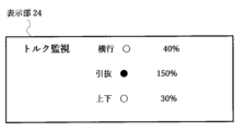
本実施の形態では、制御装置11は、サーボ系制御部13を手動操作する際の手動指令を発生する手動指令発生部14と、ティーチングの際に適切な動作を行うために必要な動作を行ってティーチングデータを取得して記憶するティーチングデータ取得部15と、トルク検知部17と、衝突検知部19と偏差クリア部21を備えている。トルク検知部17は、図2に示すように、入力部23からの手動操作により手動指令発生部14がサーボ系制御部13に移動指令[図2(A)参照]を与えてサーボモータ9を手動操作する際に上下フレーム5または取出ヘッド3に加わるトルク[図2(B)参照]を検知する。本実施の形態では、トルク検知部17は、取出ヘッド3に作用する横行方向のトルク、引抜方向のトルク及び上下方向トルクを検知できるように構成されている。トルクの検知は、モータ電流を測定して検知してもよいし、トルクセンサを用いて検知してもよい。そして本実施の形態では、図3に示すように、手動操作をするために使用されるコントローラからなる入力部23の表示部24の表示画面に、横行方向のトルク、引抜方向のトルク及び上下方向のトルクの大きさに比例する3つのトルク表示(図3では、「40%」、「150%」、「30%」の表示)をするようにしている。また表示部24の表示画面には3つのトルク表示に隣接して、退避方向を示唆する3つの示唆表示(図3では、「○」印と「●」印)がそれぞれ示されている。なおこの示唆表示は、文字表示でも、マーク表示でも、またランプ表示等のいずれでもよい。このような表示をすれば、操作者は、衝突後の退避動作を行う場合にどの方向のトルクを小さくする方向に退避すればよいのかをデータに基づいて正しく決定することができる。また熟練者で無くても、衝突後に容易に退避動作を行うことができる。
In this embodiment, the control device 11 includes a manual
衝突検知部19は、トルク検知部17の検出値が予め定めた値より大きくなったときに取出ヘッド3が周辺物に衝突したものとして動作停止指令を出力する。本実施の形態では、図2(B)に示すように、衝突検知部19は、予め定めた値を自動運転時の制限値(例えば定格トルクの300%)よりも低い値(制限値×α%:例えばα=50%)にしている。このように予め定め値を定めることにより、ティーチング等の作業や衝突後の退避動作をするときの手動操作によって、衝突時や退避動作時に必要以上の負荷が周辺物に加わるのを防止している。また本実施の形態では、衝突検知部19が、トルク検知部17の検出値が予め定めた値より大きくなったことを所定時間T1[図2(B)の「β秒」参照]検知し続けたときに、取出ヘッド3が周辺物に衝突したものとして動作停止指令[図2(E)参照]を出力する。このトルクが予め定めた値を超えたときに直ちに衝突であると判断すると、タッピング操作をするときなどに、衝突であると誤った判断をすることがあるため、β秒(具体的に0.2~0.3秒)の期間が経過した後も、トルクが制限値×α%を超え続けていた場合に、衝突が発生したと判断することとした。
When the detection value of the
さらに衝突検知部19は、動作停止指令を出力すると同時にアラーム信号[図2(C)のエラーフラグ参照]を出力する。その後、退避操作をするために、入力部23を操作してサーボ系制御部13に手動指令発生部14から再度手動操作による移動指令が入力された(図2(A)の「逆方向へ移動」のタイミングになった)後、トルク検知部17の検出値が前述の予め定めた値よりも小さくなった後(フラグ1が0になった)後、所定時間[図2(B)のγ秒参照]が経過するまで(時間T2)は、アラーム信号[図2(C)のエラーフラグ]を出力し続ける。なお「逆方向への移動」をする移動指令が入力されても衝突状態から徐々にトルクが0になっていくため、直ちに制限値×α%が0になることはない。そしてアラーム信号が出力されている間は、アラーム25は音、画像等により作業者に警告を発生する。なおγ秒の待ち時間T2を設定するのは、作業者の退避操作が誤っている場合に、作業者に退避操作のやり直しをするチャンスを与えるためである。すなわち衝突によって引抜方向のトルクが高い状態にあるときには、引抜方向のトルクが0になる方向に上下フレーム5を移動させる必要がある。しかし作業者が上下方向に上下フレーム5を移動させる手動操作をすると、取出ヘッド3を強い力で被衝突物に押しつけた状態で上限方向に移動させて、取出ヘッド3を壊してしまうことがある。そこで作業者に正しい判断をするのに必要な時間を提供するために、γ秒の待ち時間T2を設定している。
Furthermore, the
偏差クリア部21は、衝突検知部19から動作停止指令が出力されたときに、サーボモータのサーボ系制御部13のオン状態を維持して図2(B)に示すようにトルクを保持した状態で、サーボ系制御部13内で演算した偏差を0にする偏差クリア動作を行う。本実施の形態では、偏差クリア部21は、図2(D)に示すように、再度手動操作による移動指令[図2(A)参照]が入力されると、再度クリア動作を行う[図2(D)参照]。
When an operation stop command is output from the
本実施の形態の制御装置によれば、衝突検知部19から動作停止指令が出力されたときに、偏差クリア部21がサーボ系制御部のオン状態を維持してトルクを保持した状態で[図2(B)参照]、サーボ系制御部中の偏差を0にするクリア動作を行うため、偏差が0となることにより位置決め完了が確定して、再度手動指令に対応した運転が可能となる。偏差が0になっていないと、退避動作のための手動指令に先立って偏差分の動作をすることになる。この動作が、取出ヘッド3を損傷させる虞れがあるが、本実施の形態では、このような問題は発生しない。本実施の形態では、動作停止後に、脱却操作をするときには、入力部23からの操作指令通りにサーボモータ9を動作させて、上下フレーム5(取出ヘッド3)を動かすことができて、衝突状態からスムーズに退避することができる。
According to the control device of this embodiment, when the operation stop command is output from the
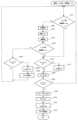
図4は、衝突検知時の実際の動作フローである。ステップST1では、トルク値が所定の値(制限値×α%)より大きいか否かが判定される。Noの場合にはステップST2で手動操作が実行され、ステップST3でサーボモータ9を駆動して軸を移動させる。そしてステップST4では、トルク値が所定の値(制限値×α%)より大きいか否かが再度判定され、Yesの場合には、ステップST5へと進んでタイマの時間T1が0であるかを判定し、YesであればステップST6でタイマの計数を開始してステップST7へと進む。またステップST5でNoの場合にもステップST7へと進んで、タイマは計数を継続する。次にステップST8で、タイマ時間T1がβであるか否かの判定がなされ、βであればステップST9へと進み、NoであればステップST1に戻る。ステップST4でNoであれば、ステップST41へと進み。タイマ時間T1が0であるか否かの判定が行われ、NoであればステップST42でタイマをオフにしてステップST43でタイマ時間T1を0にしてステップST2に戻る。ステップST41でYesの場合にもステップST2に戻る。ステップST8でタイマ時間T1がβになったことが判定されると、ステップST9でエラーフラグがONとなりステップST10で停止処理が実行される。その後ステップST11で偏差がクリアされ、ステップST12でアラームとしてエラーポップアップ(エラー表示)が出され、ステップST13でアラームとしてブザーが発報される。その後ステップST14でタイマのオフ動作が行われてステップST15でタイマ時間T1が0になる。上記の動作により、衝突が検知された後サーボ系制御部がオン状態を維持してトルクを保持した状態で偏差がリセットされる。 FIG. 4 shows an actual operation flow when a collision is detected. In step ST1, it is determined whether the torque value is greater than a predetermined value (limit value x α%). If the answer is No, a manual operation is performed in step ST2, and the servo motor 9 is driven in step ST3 to move the axis. Then, in step ST4, it is determined again whether the torque value is greater than a predetermined value (limit value x α%). If the answer is Yes, the process proceeds to step ST5 to determine whether the timer time T1 is 0. If the answer is Yes, the process proceeds to step ST6 to start counting the timer and proceeds to step ST7. Also, if the answer is No in step ST5, the process proceeds to step ST7, and the timer continues counting. Next, in step ST8, it is determined whether the timer time T1 is β. If the answer is β, the process proceeds to step ST9. If the answer is No, the process returns to step ST1. If the answer is No in step ST4, the process proceeds to step ST41. It is determined whether the timer time T1 is 0. If the answer is No, the process turns off the timer in step ST42, sets the timer time T1 to 0 in step ST43, and returns to step ST2. If the answer is Yes in step ST41, the process also returns to step ST2. If it is determined in step ST8 that the timer time T1 has reached β, an error flag is turned ON in step ST9 and a stop process is executed in step ST10. After that, the deviation is cleared in step ST11, an error pop-up (error display) is displayed as an alarm in step ST12, and a buzzer is sounded as an alarm in step ST13. After that, the timer is turned off in step ST14, and the timer time T1 becomes 0 in step ST15. Through the above operations, the deviation is reset in a state in which the servo system control unit maintains the ON state after a collision is detected and torque is maintained .
図5は衝突退避時の動作フローである。この例では開始時にトルク値が制限値×α%より大きい場合に衝突退避を行う。ステップST21でトルク値が制限値×α%より小さいか否かの判定がなされる。小さくない場合(大きい場合)にはステップST22へと進んで手動操作が実行され、ステップST23で偏差をクリアして動作停止指令をオフにして、ステップST24でサーボモータを駆動して軸を移動させる。その後、ステップST25で、トルク値が制限値×α%より小さいか否かの判定がなされる。トルク値が制限値×α%より小さい場合には、ステップST26へと進んでタイマ時間T2が0か否かの判定がなされる。タイマ時間T2が0の場合には、ステップST27でタイマの計数が開始される。タイマ時間T2が0でない場合にはステップST28でタイマの計数が継続される。ステップST25でトルク値が制限値×α%より小さくない場合には、ステップST251へと進んでタイマ時間T2が0か否かの判定がなされる。0であればステップST21に戻り、0でなければステップST252へと進んでタイマがオフとされ、ステップST253でタイマ時間T2を0(初期化)にしてステップST21へ戻る。ステップST28でのタイマ時間の計数で、タイマ時間がγになったか否かがステップST29で判定される。NOであればステップ21へ戻り、Yesであれば衝突退避動作のためにステップST30へと進んでエラーフラグをオフにし、ステップST31でブザーをオフにし、ステップST32でタイマ時間T2の計数をオフにして、ステップST33でタイマ時間T2を0にする(初期化する)。これにより衝突状態からの退避がなされる。 Figure 5 shows the operation flow during collision avoidance. In this example, collision avoidance is performed when the torque value is greater than the limit value × α% at the start. In step ST21, it is determined whether the torque value is smaller than the limit value × α%. If it is not smaller (if it is greater), the process proceeds to step ST22, where manual operation is performed, the deviation is cleared in step ST23, the operation stop command is turned off, and the servo motor is driven in step ST24 to move the axis. Then, in step ST25, it is determined whether the torque value is smaller than the limit value × α%. If the torque value is smaller than the limit value × α%, the process proceeds to step ST26, where it is determined whether the timer time T2 is 0 or not. If the timer time T2 is 0, the timer starts counting in step ST27. If the timer time T2 is not 0, the timer continues counting in step ST28. If the torque value is not smaller than the limit value × α% in step ST25, the process proceeds to step ST251, where it is determined whether the timer time T2 is 0 or not. If it is 0, the process returns to step ST21; if it is not 0, the process proceeds to step ST252, where the timer is turned off, and in step ST253, the timer time T2 is set to 0 (initialized), and the process returns to step ST21. In step ST28, it is determined in step ST29 whether the timer time has reached γ in counting the timer time. If it is NO, the process returns to step ST21; if it is YES, the process proceeds to step ST30 for collision avoidance operation, where the error flag is turned off, in step ST31 the buzzer is turned off, in step ST32 the counting of timer time T2 is turned off, and in step ST33 the timer time T2 is set to 0 (initialized). This allows the vehicle to avoid the collision state.
[変形例]
トルク検知部は、取出ヘッドに種々の方向から作用するトルクの作用方向を検知できるように構成されているのが好ましい。例えばサーボモータが駆動する軸数が、5軸、6軸等の多軸の場合には、多軸のすべてのトルクを検出できるようにトルク検知部を構成すればよい。また取出ヘッドが姿勢制御装置に装着される場合には、姿勢制御装置から取出ヘッドに加わるトルクも、トルク検知部で検知できるようにすればよい。さらに手動操作をするために使用される入力部の表示部には、トルク検知部が検知するすべてのトルクの大きさに比例するトルク表示を示すのが好ましい。これらのトルク表示は、数値表示、バーグラフ表示、メータ表示な任意の表示をすることができる。また入力部の表示部のトルク表示に隣接して、退避方向を示唆する示唆表示がそれぞれ示されているのが好ましい。この示唆は、文字表示でも、マーク表示でも、またランプ表示等のいずれでもよい。
[Modification]
The torque detector is preferably configured to detect the direction of torque acting on the take-out head from various directions. For example, when the number of axes driven by the servo motor is multiple, such as 5-axis or 6-axis, the torque detector may be configured to detect all torques of the multiple axes. When the take-out head is attached to a posture control device, the torque detector may detect the torque applied to the take-out head from the posture control device. Furthermore, the display of the input unit used for manual operation preferably shows torque indications proportional to the magnitude of all torques detected by the torque detector. These torque indications may be displayed in any form, such as numerical values, bar graphs, or meters. Furthermore, it is preferable that a suggestion indication suggesting the direction of evacuation is displayed adjacent to the torque indication on the display of the input unit. This suggestion may be displayed in the form of letters, marks, lamps, or the like.
本発明によれば、動作停止指令が出力されたときに、偏差クリア部がサーボ系制御部のオン状態を維持してトルクを保持した状態で、サーボ系制御部中の偏差を0にするクリア動作を行うため、偏差が0となることにより位置決め完了が確定して、再度運転が可能となる。その結果、動作停止後に、退避操作をするときには、操作指令通りにサーボモータを動作させて、上下フレーム及び取出ヘッドを動かすことができて、衝突状態からスムーズに退避することができる。 According to the present invention, when an operation stop command is output, the deviation clearing unit maintains the on state of the servo system control unit to hold the torque and performs a clearing operation to set the deviation in the servo system control unit to 0, so that the positioning completion is confirmed when the deviation becomes 0, and operation can be resumed. As a result, when performing an evacuation operation after the operation is stopped, the servo motor can be operated according to the operation command to move the upper and lower frames and the take-out head, and the collision state can be smoothly evacuated.
1 成形品取出機
3 取出ヘッド
5 上下フレーム
7 搬送機構
9 サーボモータ
10 エンコーダ
11 制御装置
13 サーボ系制御部
14 手動指令発生部
15 ティーチングデータ取得部
17 トルク検知部
19 衝突検知部
21 偏差クリア部
23 入力部
24 表示部
25 アラーム
REFERENCE SIGNS
Claims (9)
前記手動指令発生部から出力される前記手動指令により前記サーボ系制御部に動作指令を与えて前記サーボモータを手動操作する際に前記フレームに加わるトルクを検知するトルク検知部と、
前記トルク検知部の検出値が予め定めた値より大きくなったときに前記取出ヘッドが周辺物に衝突したものとして動作停止指令を出力する衝突検知部と、
前記動作停止指令が出力されたときに、前記サーボ系制御部のオン状態を維持して前記トルクを保持した状態で、前記サーボ系制御部中の前記偏差を0にするクリア動作を行う偏差クリア部をさらに備えたことを特徴とする成形品取出機の制御装置。 A control device for a molded product removal machine, comprising: a servo system control section which detects, by an encoder, a position and a speed of a drive section of a servo motor which drives a frame having a removal head in the molded product removal machine, obtains a deviation between the detected value and a position command and a speed command value, and controls the servo motor by performing a feedback control of the position and the speed of the drive section based on the deviation; and a manual command generating section which generates a manual command when the servo system control section is manually operated,
a torque detection unit that detects a torque applied to the frame when the servo motor is manually operated by giving an operation command to the servo system control unit according to the manual command output from the manual command generation unit;
a collision detection unit that outputs an operation stop command when the torque detection unit detects that the pickup head has collided with a surrounding object when the torque detection unit detects that ...
a deviation clearing unit that performs a clearing operation to set the deviation in the servo system control unit to zero while maintaining the on state of the servo system control unit and holding the torque when the operation stop command is output.
前記手動操作をするために使用される入力部の表示部には、前記トルクの作用方向と前記トルクの大きさに比例するトルク表示が示されている請求項1乃至5のいずれか1項に記載の成形品取出機の制御装置。 The torque detector is configured to detect a direction of torque acting on the extraction head,
6. A control device for a molded product removal machine as described in any one of claims 1 to 5, wherein a display unit of an input unit used for the manual operation shows a torque display proportional to the direction of action of the torque and the magnitude of the torque.
前記手動操作をするために使用される入力部の表示部には、前記横行方向のトルク、前記引抜方向のトルク及び前記上下方向のトルクの大きさに比例する3つのトルク表示が示されている請求項6に記載の成形品取出機の制御装置。 The torque detector is configured to detect a lateral torque, a pull-out torque, and a vertical torque acting on the take-out head,
A control device for a molded product removal machine as described in claim 6, wherein the display unit of the input unit used for the manual operation shows three torque indications proportional to the magnitude of the torque in the lateral direction, the torque in the withdrawal direction, and the torque in the vertical direction.
9. The control device for a molded product removing machine according to claim 8, wherein the display unit displays three indications each indicating a retraction direction adjacent to the three torque indications.
Priority Applications (5)
| Application Number | Priority Date | Filing Date | Title |
|---|---|---|---|
| JP2020202992A JP7588936B2 (en) | 2020-12-07 | 2020-12-07 | Control device for molding removal machine |
| CN202111479367.2A CN114590553B (en) | 2020-12-07 | 2021-12-06 | Control device of molded article extractor |
| EP21212561.1A EP4008517B1 (en) | 2020-12-07 | 2021-12-06 | Control system for apparatus for taking out molded product |
| US17/542,866 US12246474B2 (en) | 2020-12-07 | 2021-12-06 | Control system for apparatus for taking out molded product that detects collision based on torque |
| KR1020210173489A KR20220080721A (en) | 2020-12-07 | 2021-12-07 | Control device of apparatus for taking out molded product |
Applications Claiming Priority (1)
| Application Number | Priority Date | Filing Date | Title |
|---|---|---|---|
| JP2020202992A JP7588936B2 (en) | 2020-12-07 | 2020-12-07 | Control device for molding removal machine |
Publications (2)
| Publication Number | Publication Date |
|---|---|
| JP2022090541A JP2022090541A (en) | 2022-06-17 |
| JP7588936B2 true JP7588936B2 (en) | 2024-11-25 |
Family
ID=79185632
Family Applications (1)
| Application Number | Title | Priority Date | Filing Date |
|---|---|---|---|
| JP2020202992A Active JP7588936B2 (en) | 2020-12-07 | 2020-12-07 | Control device for molding removal machine |
Country Status (5)
| Country | Link |
|---|---|
| US (1) | US12246474B2 (en) |
| EP (1) | EP4008517B1 (en) |
| JP (1) | JP7588936B2 (en) |
| KR (1) | KR20220080721A (en) |
| CN (1) | CN114590553B (en) |
Families Citing this family (1)
| Publication number | Priority date | Publication date | Assignee | Title |
|---|---|---|---|---|
| CN117532392A (en) * | 2023-12-28 | 2024-02-09 | 广东义同智能装备有限公司 | Protection method and system for numerical control machine after collision |
Citations (4)
| Publication number | Priority date | Publication date | Assignee | Title |
|---|---|---|---|---|
| JP2000271886A (en) | 1999-03-26 | 2000-10-03 | Fanuc Ltd | Industrial robot |
| JP2015217468A (en) | 2014-05-16 | 2015-12-07 | キヤノン株式会社 | Method for controlling robot system, program, recording medium, robot system, and diagnostic device |
| JP2017019057A (en) | 2015-07-13 | 2017-01-26 | セイコーエプソン株式会社 | Robot control device, robot and robot system |
| JP2017030058A (en) | 2015-07-29 | 2017-02-09 | セイコーエプソン株式会社 | Robot, robot controller and robot system |
Family Cites Families (17)
| Publication number | Priority date | Publication date | Assignee | Title |
|---|---|---|---|---|
| JPS526555B2 (en) | 1972-10-30 | 1977-02-23 | ||
| US4065212A (en) | 1975-06-30 | 1977-12-27 | International Business Machines Corporation | Inspection tool |
| JP2665984B2 (en) | 1989-12-26 | 1997-10-22 | ファナック株式会社 | Collision detection method using disturbance estimation observer |
| JP2608161B2 (en) * | 1990-03-29 | 1997-05-07 | ファナック株式会社 | Industrial robot stop control method |
| JP3079047B2 (en) * | 1996-10-22 | 2000-08-21 | ファナック株式会社 | Movable member collision detection device for electric injection molding machine |
| JP4055090B2 (en) * | 1997-07-08 | 2008-03-05 | 株式会社安川電機 | Robot control device |
| JP2000277039A (en) | 1999-03-26 | 2000-10-06 | Toshiba Corp | Image display device and method of manufacturing the same |
| JP3526555B2 (en) | 2001-03-01 | 2004-05-17 | 株式会社スター精機 | Method for controlling the movement of the chuck part of the molded product take-out machine |
| JP2004025369A (en) * | 2002-06-26 | 2004-01-29 | Denso Wave Inc | Control method and control device of robot |
| WO2009128156A1 (en) * | 2008-04-17 | 2009-10-22 | 三菱電機株式会社 | Collision detector and method for detecting collision in processing machine |
| CN102792238A (en) * | 2010-03-08 | 2012-11-21 | 三菱电机株式会社 | Numerical control device and control method of numerical control device |
| CN106239516B (en) * | 2015-06-03 | 2021-09-24 | 精工爱普生株式会社 | Robot Controllers, Robots, and Robot Systems |
| JP6779766B2 (en) * | 2015-12-09 | 2020-11-04 | 株式会社ユーシン精機 | Molded product take-out machine |
| US11397563B2 (en) * | 2017-07-21 | 2022-07-26 | Husky Injection Molding Systems Ltd. | Programming a protection device for a molding machine |
| JP6731893B2 (en) * | 2017-07-31 | 2020-07-29 | ヤンマーパワーテクノロジー株式会社 | Work vehicle |
| CN112739515B (en) * | 2018-09-21 | 2022-11-29 | 佳能弗吉尼亚股份有限公司 | injection molding system |
| EP3689555A1 (en) * | 2019-02-04 | 2020-08-05 | Siemens Aktiengesellschaft | Force-limited method of at least one element of a production machine in manual operation |
-
2020
- 2020-12-07 JP JP2020202992A patent/JP7588936B2/en active Active
-
2021
- 2021-12-06 CN CN202111479367.2A patent/CN114590553B/en active Active
- 2021-12-06 US US17/542,866 patent/US12246474B2/en active Active
- 2021-12-06 EP EP21212561.1A patent/EP4008517B1/en active Active
- 2021-12-07 KR KR1020210173489A patent/KR20220080721A/en active Pending
Patent Citations (4)
| Publication number | Priority date | Publication date | Assignee | Title |
|---|---|---|---|---|
| JP2000271886A (en) | 1999-03-26 | 2000-10-03 | Fanuc Ltd | Industrial robot |
| JP2015217468A (en) | 2014-05-16 | 2015-12-07 | キヤノン株式会社 | Method for controlling robot system, program, recording medium, robot system, and diagnostic device |
| JP2017019057A (en) | 2015-07-13 | 2017-01-26 | セイコーエプソン株式会社 | Robot control device, robot and robot system |
| JP2017030058A (en) | 2015-07-29 | 2017-02-09 | セイコーエプソン株式会社 | Robot, robot controller and robot system |
Also Published As
| Publication number | Publication date |
|---|---|
| US20220176596A1 (en) | 2022-06-09 |
| EP4008517A1 (en) | 2022-06-08 |
| US12246474B2 (en) | 2025-03-11 |
| KR20220080721A (en) | 2022-06-14 |
| CN114590553A (en) | 2022-06-07 |
| EP4008517B1 (en) | 2025-11-26 |
| CN114590553B (en) | 2025-12-23 |
| JP2022090541A (en) | 2022-06-17 |
Similar Documents
| Publication | Publication Date | Title |
|---|---|---|
| JP4261470B2 (en) | Control device | |
| US11531319B2 (en) | Failure prediction device and machine learning device | |
| EP0540753B1 (en) | System for controlling industrial robot | |
| US6409495B1 (en) | Mold protection device for injection molding machine | |
| EP0566741A1 (en) | Abnormal load detecting method | |
| US10747197B2 (en) | Abnormally factor identification apparatus | |
| JP2003326438A (en) | Tool abnormality detection device | |
| JP4897632B2 (en) | Machine tool control device having a collision detection function | |
| JP2008176559A (en) | Control unit | |
| EP0203199B1 (en) | Injection molding machine which uses a servo motor and which is provided with a protecting function | |
| JP2005327191A (en) | Servo control device | |
| JP7588936B2 (en) | Control device for molding removal machine | |
| US20060184256A1 (en) | Controller | |
| JP6440984B2 (en) | Numerical control device that performs acceleration / deceleration control by stopping distance | |
| JP4258718B2 (en) | Robot controller | |
| JP6077497B2 (en) | Numerical control device for repetitive machining | |
| US20200159190A1 (en) | Numerical controller | |
| JP2005052941A (en) | Apparatus for mounting workpiece | |
| JP6441253B2 (en) | Numerical control device that facilitates measures after detecting interference | |
| JP2000181521A (en) | Controller for automatic machine | |
| JPH0976144A (en) | Machining state monitoring method in machine tool | |
| CN113285653A (en) | Collision protection system and method for servo control device and computer readable medium | |
| JP2005321979A (en) | Numerical controller | |
| US12186908B2 (en) | Force-limited movement of at least one element of a production machine in manual operation | |
| US20210191346A1 (en) | Abnormality detection device and abnormality detection method |
Legal Events
| Date | Code | Title | Description |
|---|---|---|---|
| RD02 | Notification of acceptance of power of attorney |
Free format text: JAPANESE INTERMEDIATE CODE: A7422 Effective date: 20230816 |
|
| A621 | Written request for application examination |
Free format text: JAPANESE INTERMEDIATE CODE: A621 Effective date: 20231025 |
|
| A977 | Report on retrieval |
Free format text: JAPANESE INTERMEDIATE CODE: A971007 Effective date: 20240726 |
|
| A131 | Notification of reasons for refusal |
Free format text: JAPANESE INTERMEDIATE CODE: A131 Effective date: 20240806 |
|
| A521 | Request for written amendment filed |
Free format text: JAPANESE INTERMEDIATE CODE: A523 Effective date: 20241007 |
|
| TRDD | Decision of grant or rejection written | ||
| A01 | Written decision to grant a patent or to grant a registration (utility model) |
Free format text: JAPANESE INTERMEDIATE CODE: A01 Effective date: 20241112 |
|
| A61 | First payment of annual fees (during grant procedure) |
Free format text: JAPANESE INTERMEDIATE CODE: A61 Effective date: 20241112 |
|
| R150 | Certificate of patent or registration of utility model |
Ref document number: 7588936 Country of ref document: JP Free format text: JAPANESE INTERMEDIATE CODE: R150 |
|
| S533 | Written request for registration of change of name |
Free format text: JAPANESE INTERMEDIATE CODE: R313533 |
|
| R350 | Written notification of registration of transfer |
Free format text: JAPANESE INTERMEDIATE CODE: R350 |