JP7588926B2 - Heat insulating cover device for piping heat insulating structure and its manufacturing method - Google Patents
Heat insulating cover device for piping heat insulating structure and its manufacturing method Download PDFInfo
- Publication number
- JP7588926B2 JP7588926B2 JP2024526736A JP2024526736A JP7588926B2 JP 7588926 B2 JP7588926 B2 JP 7588926B2 JP 2024526736 A JP2024526736 A JP 2024526736A JP 2024526736 A JP2024526736 A JP 2024526736A JP 7588926 B2 JP7588926 B2 JP 7588926B2
- Authority
- JP
- Japan
- Prior art keywords
- ring
- chassis
- plate portion
- vertical plate
- cover
- Prior art date
- Legal status (The legal status is an assumption and is not a legal conclusion. Google has not performed a legal analysis and makes no representation as to the accuracy of the status listed.)
- Active
Links
Images


Classifications
-
- F—MECHANICAL ENGINEERING; LIGHTING; HEATING; WEAPONS; BLASTING
- F16—ENGINEERING ELEMENTS AND UNITS; GENERAL MEASURES FOR PRODUCING AND MAINTAINING EFFECTIVE FUNCTIONING OF MACHINES OR INSTALLATIONS; THERMAL INSULATION IN GENERAL
- F16L—PIPES; JOINTS OR FITTINGS FOR PIPES; SUPPORTS FOR PIPES, CABLES OR PROTECTIVE TUBING; MEANS FOR THERMAL INSULATION IN GENERAL
- F16L59/00—Thermal insulation in general
- F16L59/02—Shape or form of insulating materials, with or without coverings integral with the insulating materials
-
- F—MECHANICAL ENGINEERING; LIGHTING; HEATING; WEAPONS; BLASTING
- F16—ENGINEERING ELEMENTS AND UNITS; GENERAL MEASURES FOR PRODUCING AND MAINTAINING EFFECTIVE FUNCTIONING OF MACHINES OR INSTALLATIONS; THERMAL INSULATION IN GENERAL
- F16L—PIPES; JOINTS OR FITTINGS FOR PIPES; SUPPORTS FOR PIPES, CABLES OR PROTECTIVE TUBING; MEANS FOR THERMAL INSULATION IN GENERAL
- F16L59/00—Thermal insulation in general
- F16L59/10—Bandages or covers for the protection of the insulation, e.g. against the influence of the environment or against mechanical damage
- F16L59/11—Rigid covers for elbows
-
- F—MECHANICAL ENGINEERING; LIGHTING; HEATING; WEAPONS; BLASTING
- F16—ENGINEERING ELEMENTS AND UNITS; GENERAL MEASURES FOR PRODUCING AND MAINTAINING EFFECTIVE FUNCTIONING OF MACHINES OR INSTALLATIONS; THERMAL INSULATION IN GENERAL
- F16L—PIPES; JOINTS OR FITTINGS FOR PIPES; SUPPORTS FOR PIPES, CABLES OR PROTECTIVE TUBING; MEANS FOR THERMAL INSULATION IN GENERAL
- F16L59/00—Thermal insulation in general
- F16L59/02—Shape or form of insulating materials, with or without coverings integral with the insulating materials
- F16L59/021—Shape or form of insulating materials, with or without coverings integral with the insulating materials comprising a single piece or sleeve, e.g. split sleeves; consisting of two half sleeves; comprising more than two segments
- F16L59/024—Shape or form of insulating materials, with or without coverings integral with the insulating materials comprising a single piece or sleeve, e.g. split sleeves; consisting of two half sleeves; comprising more than two segments consisting of two half sleeves
-
- F—MECHANICAL ENGINEERING; LIGHTING; HEATING; WEAPONS; BLASTING
- F16—ENGINEERING ELEMENTS AND UNITS; GENERAL MEASURES FOR PRODUCING AND MAINTAINING EFFECTIVE FUNCTIONING OF MACHINES OR INSTALLATIONS; THERMAL INSULATION IN GENERAL
- F16L—PIPES; JOINTS OR FITTINGS FOR PIPES; SUPPORTS FOR PIPES, CABLES OR PROTECTIVE TUBING; MEANS FOR THERMAL INSULATION IN GENERAL
- F16L59/00—Thermal insulation in general
- F16L59/04—Arrangements using dry fillers, e.g. using slag wool
-
- F—MECHANICAL ENGINEERING; LIGHTING; HEATING; WEAPONS; BLASTING
- F16—ENGINEERING ELEMENTS AND UNITS; GENERAL MEASURES FOR PRODUCING AND MAINTAINING EFFECTIVE FUNCTIONING OF MACHINES OR INSTALLATIONS; THERMAL INSULATION IN GENERAL
- F16L—PIPES; JOINTS OR FITTINGS FOR PIPES; SUPPORTS FOR PIPES, CABLES OR PROTECTIVE TUBING; MEANS FOR THERMAL INSULATION IN GENERAL
- F16L59/00—Thermal insulation in general
- F16L59/14—Arrangements for the insulation of pipes or pipe systems
- F16L59/16—Arrangements specially adapted to local requirements at flanges, junctions, valves or the like
- F16L59/161—Housings for valves, tee pieces, or the like
Landscapes
- Engineering & Computer Science (AREA)
- General Engineering & Computer Science (AREA)
- Mechanical Engineering (AREA)
- Thermal Insulation (AREA)
Description
本発明は、配管の外部表面を取り囲むように設置される配管断熱構造体の断熱カバー装置に関し、より詳細には、配管を取り囲む断熱材を覆う仕上げカバーおよび保護シートと、仕上げカバーと保護シートとの間を連結するソケットとを含む、配管断熱構造体の断熱カバー装置およびその製造方法に関する。 The present invention relates to an insulating cover device for a pipe insulation structure that is installed to surround the external surface of a pipe, and more specifically, to an insulating cover device for a pipe insulation structure that includes a finishing cover and a protective sheet that cover the insulation material surrounding the pipe, and a socket that connects between the finishing cover and the protective sheet, and a method for manufacturing the same.
一般に、オフィスビル、産業用建物及びアパートなどの建物には各種配管設備が設置され、これらの配管設備は、保温及び保冷、または付加的に配管設備の寿命延長及び外観デザインのための目的で保温カバーが設置されて使用され、このような保温カバーは、主に配管設備においてバルブ、T型管、エルボ、直管などに使用される。 Generally, various piping equipment is installed in buildings such as office buildings, industrial buildings, and apartments, and these piping equipment are used with thermal insulation covers installed for the purpose of keeping the equipment hot or cold, or additionally for the purpose of extending the life of the piping equipment and improving the appearance design. Such thermal insulation covers are mainly used for valves, T-pipes, elbows, straight pipes, etc. in piping equipment.
特に、発電所(原子力、火力など)および石油化学プラントなどでは、ボイラで生産された高温高圧の蒸気がタービンに回転力を提供して最終的に電気的エネルギーを生産する。高温高圧の蒸気と温水は、配管を介して各系統別に速い速度で移送されており、 移送過程中に配管内部の流体摩擦及びキャビテーション(Cavitation)などによる配管厚さが薄くなって正常運転中に系統の安全上の事故を誘発させる危険性が潜在しており、発電設備の計画予防整備中に配管の減肉状態(腐食などの原因により配管の壁が薄くなる状態)の点検で設備の健全性を確認している。 In particular, in power plants (nuclear, thermal, etc.) and petrochemical plants, high-temperature, high-pressure steam produced in boilers provides rotational force to turbines, ultimately producing electrical energy. High-temperature, high-pressure steam and hot water are transported at high speeds through pipes in various systems, and during the transport process, fluid friction and cavitation inside the pipes can cause the pipes to thin, potentially resulting in a safety accident in the system during normal operation. Therefore, during planned preventive maintenance of power generation equipment, the integrity of the equipment is confirmed by inspecting the pipes for thinning (a condition in which the walls of the pipes become thinner due to corrosion, etc.).
減肉検査を実施する際に、断熱材で施工された場合には、配管の外部に仕上げられた金属材質の仕上げカバー及び断熱材等を順次撤去した後に減肉検査を実施し、減肉検査が完了した以降は新たな断熱材を取り付け、仕上げカバーで仕上げる方式で行われている。 When conducting a wall-thinning inspection, if insulation is used, the metal finishing cover and insulation material attached to the outside of the pipe are sequentially removed before the wall-thinning inspection is carried out. After the wall-thinning inspection is completed, new insulation material is installed and finished with a finishing cover.
このような減肉検査後の断熱材施工方式は、毎年撤去される断熱材及び仕上げカバーの廃棄量により資材の莫大な浪費を引き起こし、特にエルボまたはTジョイント部分の場合には、直管の断熱材の設置に比べて高度の熟練した機能が要求されるだけでなく、誤って施工された場合、断熱隙間(thermal notch)の発生により熱疲労現象(thermal stress)が増加してその部分に対する減肉現象が顕著に進む可能性があり、これにより全配管の寿命を短縮させるという問題点があった。 This method of installing insulation after thinning inspection results in a huge waste of materials due to the amount of insulation and finishing covers that are removed every year, and in particular in the case of elbow or T-joint parts, it requires a higher level of skill than installing insulation on straight pipes. If installed incorrectly, the occurrence of thermal notches can increase thermal stress and cause significant thinning in that area, shortening the lifespan of the entire pipe.
前述した問題点を解決することができるように、着脱が容易であり、断熱隙間の発生を減らすことにより、配管の減肉検査及び断熱材の施工作業を簡便にすることができる配管用断熱構造が提案されている。 In order to solve the problems mentioned above, a pipe insulation structure has been proposed that is easy to attach and detach, reduces the occurrence of insulation gaps, and simplifies pipe thinning inspection and insulation installation work.
前述したような従来の配管用断熱構造は、特許文献1:韓国登録特許第10-1820450号(2018年1月15日)に開示されており、図1及び図2を参照して従来の配管用断熱構造を説明すると、次の通りである。 The conventional insulation structure for piping as described above is disclosed in Patent Document 1: Korean Patent Registration No. 10-1820450 (January 15, 2018), and the conventional insulation structure for piping is described below with reference to Figures 1 and 2.
図1及び図2を参照すると、従来の配管用断熱構造は、配管10の幅方向の一側と他側を囲む半円筒状の第1断熱材110及び第2断熱材120と、第1断熱材110と第2断熱材120の外部表面を覆うアルミニウム材質の第1仕上げカバー210及び第2仕上げカバー220と、第1断熱材110と第2断熱材120の表面のうち、第1仕上げカバー210または第2仕上げカバー220によって覆われていない部位を覆う第1保護シート310および第2保護シート320と、第1仕上げカバー210と第2仕上げカバー220を分離可能に結合させるために締結フック510、回転片520および締結リンク530を含む締結ユニット500と、第1仕上げカバー210の幅方向の両端がそれぞれ挿入される一対の第1締結ソケット710と、第2仕上げカバー220の幅方向の両端がそれぞれ挿入される一対の第2締結ソケット720と、第1締結ソケット710と第2締結ソケット720とが互いに向かい合う面に挿入される締結パッキン740と、第1保護シート310の幅方向の一側を貫通した後、第1締結ソケット710のうち第1仕上げカバー210が挿入された部位を貫通するように締結され、第2保護シート320の幅方向の一側を貫通した後、第2締結ソケット720のうち第2仕上げカバー220が挿入された部位を貫通するように締結される多数個の締結リベット730と、を含む。また、第1保護シート310と第2保護シート320の幅方向の両側は、締結リベット730が貫通する部位が二重に重なるように折り畳まれる。また、第1保護シート310と第2保護シート320の幅方向の両側のうち、折り畳まれた部位には固定ワイヤー330が挿入される。そして、締結リベット730のヘッドが装着される締結ワッシャー750が提供される。
1 and 2, the conventional insulation structure for piping includes a semi-cylindrical
従来技術は、ソケット710、720及び仕上げカバー210、220がアルミニウム材質であり、これに結合されなければならない保護シート310、320がアルミニウム材質とうまく結合できないセラミック繊維などの織物材質であるから、ソケット710、720及び仕上げカバー210、220に対する保護シート310、320の結合にリベット730を利用する。しかし、従来のリベットによる結合方法は、面倒で複雑であるという欠点がある。しかも、リベットが外部に突出して外観も悪いという欠点がある。
In the conventional technology, the
本発明の目的は、配管を取り囲む断熱材を覆う仕上げカバー及び保護シートと、仕上げカバーと保護シートとの間を連結するソケットと、を含み、リベット等の追加的な要素なしで、保護シートと仕上げカバーがソケットに容易かつ簡単に結合できる、配管断熱構造体の断熱カバー装置及びその製造方法を提供することにある。 The object of the present invention is to provide an insulation cover device for a piping insulation structure, which includes a finishing cover and a protective sheet that cover the insulation material surrounding the piping, and a socket that connects the finishing cover and the protective sheet, and in which the protective sheet and the finishing cover can be easily and simply joined to the socket without the need for additional elements such as rivets, and a method for manufacturing the same.
上記目的を達成するための本発明の一態様による配管断熱構造体の断熱カバー装置は、配管を囲む断熱材の外部表面の一部を覆う仕上げカバーと、前記断熱材の外部表面のうち前記仕上げカバーによって覆われない部位を覆うように配置され、末端に鋼線の挿入された輪部を有する保護シートと、前記仕上げカバーと前記保護シートとの間を連結するための連結ソケットと、を含み、前記連結ソケットは、水平板部と、前記水平板部から垂直方向に延びた内側垂直板部と、前記水平板部から垂直方向に延び、前記内側垂直板部との間に前記仕上げカバーの挿入される挿入溝を形成する外側垂直板部と、を含み、前記挿入溝に挿入された前記仕上げカバーは、前記内側垂直板部にリング状に加圧成形される複数個のリング状加圧部によって前記連結ソケットと互いに結合され、前記保護シートは、前記輪部が前記内側垂直板部から切り出されて曲げられたり巻き上げられたりする複数個のクランピングフックによって囲まれる形態でクランプされることにより、前記連結ソケットと互いに結合される。 The insulation cover device for a pipe insulation structure according to one aspect of the present invention for achieving the above object includes a finishing cover that covers a part of the external surface of the insulation surrounding the pipe, a protective sheet that is arranged to cover the part of the external surface of the insulation that is not covered by the finishing cover and has a ring part with a steel wire inserted at its end, and a connecting socket for connecting between the finishing cover and the protective sheet, the connecting socket includes a horizontal plate part, an inner vertical plate part extending vertically from the horizontal plate part, and an outer vertical plate part extending vertically from the horizontal plate part and forming an insertion groove into which the finishing cover is inserted between the inner vertical plate part, the finishing cover inserted into the insertion groove is connected to the connecting socket by a plurality of ring-shaped pressurizing parts that are pressurized into a ring shape on the inner vertical plate part, and the protective sheet is connected to the connecting socket by clamping in a form in which the ring part is surrounded by a plurality of clamping hooks that are cut out from the inner vertical plate part and bent or rolled up.
前記仕上げカバーと前記連結ソケットは軟質金属材質で形成され、前記保護シートは織物材質で形成され得る。 The finishing cover and the connecting socket may be made of a soft metal material, and the protective sheet may be made of a woven material.
前記複数個のリング状加圧部は、リング状断面のパンチ(punch)で前記内側垂直板部をプレス加工して形成されたものであり、前記仕上げカバー及び前記外側垂直板部のそれぞれには、前記リング状加圧部に押圧されてリング状の溝が形成されることにより、前記内側垂直板部、前記仕上げカバー及び前記外側垂直板部が互いに係合されるようにすることができる。 The multiple ring-shaped pressure members are formed by pressing the inner vertical plate with a punch having a ring-shaped cross section, and a ring-shaped groove is formed in each of the finishing cover and the outer vertical plate by pressing the finishing cover against the ring-shaped pressure members, so that the inner vertical plate, the finishing cover, and the outer vertical plate can be engaged with each other.
前記保護シートは、前記水平板部と前記内側垂直板部との間のコーナーに前記輪部が置かれるように配置された状態で、前記内側垂直板部から切り出されて曲げられたり巻き上げられたりした前記クランピングフックが前記輪部を囲むようにクランプされることにより、前記連結ソケットと互いに結合されることができる。 The protective sheet can be connected to the connecting socket by being positioned so that the loop portion is placed at the corner between the horizontal plate portion and the inner vertical plate portion, and the clamping hook, which is cut out from the inner vertical plate portion and bent or rolled up, is clamped to surround the loop portion.
前記仕上げカバーは、第1組立端部には第1シャーシ挿入溝が形成され、第2組立端部には第2シャーシ挿入溝が形成された軟質金属材質の少なくとも一つの連結シャーシと、軟質金属材質の複数のプレートと、を備え、前記複数のプレートのうちのいずれか一つである第1プレートの一端部が前記第1シャーシ挿入溝に挿入され、前記第1プレートに隣接した第2プレートの一端部が前記第2シャーシ挿入溝に挿入されるようにした状態で、前記連結シャーシの内面から前記第1シャーシ挿入溝に向かってリング状に加圧成形される複数個のリング状加圧部によって前記連結シャーシと前記第1プレートとが結合され、前記連結シャーシの内面から前記第2シャーシ挿入溝に向かってリング状に加圧成形される複数個のリング状加圧部によって前記連結シャーシと前記第2プレートとが結合されるようにする方式で、前記複数のプレートと前記少なくとも一つの連結シャーシとが前記配管の曲面に対応して結合された構造を有することができる。 The finishing cover includes at least one connecting chassis made of a soft metal material, with a first chassis insertion groove formed at a first assembly end and a second chassis insertion groove formed at a second assembly end, and a plurality of plates made of a soft metal material. In a state where one end of a first plate, which is one of the plurality of plates, is inserted into the first chassis insertion groove and one end of a second plate adjacent to the first plate is inserted into the second chassis insertion groove, the connecting chassis and the first plate are joined by a plurality of ring-shaped pressurizing parts that are pressurized from the inner surface of the connecting chassis toward the first chassis insertion groove in a ring shape, and the connecting chassis and the second plate are joined by a plurality of ring-shaped pressurizing parts that are pressurized from the inner surface of the connecting chassis toward the second chassis insertion groove in a ring shape, so that the plurality of plates and the at least one connecting chassis are joined in accordance with the curved surface of the piping.
前記少なくとも一つの連結シャーシは、断面が「H」字状に平板形状を有するか、或いは前記第1組立端部と前記第2組立端部とが互いに一定角度をなすように中間部分が曲げられた曲面を成したりする形状を有することができる。 The at least one connecting chassis may have a flat "H"-shaped cross section, or may have a curved shape with the middle portion bent so that the first assembly end and the second assembly end form a certain angle with each other.
前記少なくとも一つの連結シャーシ、及び前記少なくとも一つの連結シャーシに挿入されたプレートは、前記リング状加圧部に押圧されてリング状の溝が形成されることにより、前記少なくとも一つの連結シャーシと前記プレートとが互いに係合されることができる。 The at least one connecting chassis and the plate inserted into the at least one connecting chassis are pressed against the ring-shaped pressure section to form a ring-shaped groove, so that the at least one connecting chassis and the plate can be engaged with each other.
上記目的を達成するための本発明の他の態様による配管断熱構造体の断熱カバー装置の製造方法は、配管を囲む断熱材の外部表面を覆う仕上げカバーと、前記断熱材の外部表面のうち、前記仕上げカバーによって覆われない部位を覆うように配置され、末端に鋼線の挿入された輪部を有する保護シートとを準備し、前記仕上げカバーと前記保護シートとを連結するために、水平板部と、前記水平板部から垂直方向に延びた内側垂直板部と、前記水平板部から垂直方向に延び、前記内側垂直板部との間に挿入溝を形成する外側垂直板部とを一体に含む連結ソケットを準備するステップと、前記仕上げカバーの端部を前記挿入溝に挿入し、前記挿入溝に前記仕上げカバーの端部が挿入された状態で、前記内側垂直板部に複数個のリング状加圧部を形成して、前記仕上げカバーと前記連結ソケットとを結合するステップと、前記保護シートの輪部が前記連結ソケットの前記水平板部と前記内側垂直板部との間のコーナーに置かれた状態で、前記内側垂直板部を切り出して曲げたり巻き上げたりしたクランピングフックで、前記鋼線の挿入された輪部を囲む形態でクランプすることにより、前記保護シートと前記連結ソケットとを結合するステップと、を備える。 In order to achieve the above object, a method for manufacturing an insulation cover device for a piping insulation structure according to another aspect of the present invention includes the steps of preparing a finishing cover that covers the outer surface of the insulation material surrounding the piping, and a protective sheet that is arranged to cover the portion of the outer surface of the insulation material that is not covered by the finishing cover and has a ring portion with a steel wire inserted at its end, and preparing a connecting socket that includes a horizontal plate portion, an inner vertical plate portion that extends vertically from the horizontal plate portion, and an outer vertical plate portion that extends vertically from the horizontal plate portion and forms an insertion groove between the horizontal plate portion and the inner vertical plate portion, in order to connect the finishing cover and the protective sheet. the step of inserting the end of the finishing cover into the insertion groove, forming a plurality of ring-shaped pressure parts on the inner vertical plate part with the end of the finishing cover inserted in the insertion groove, and joining the finishing cover to the connecting socket; and the step of clamping the inner vertical plate part with a clamping hook cut out, bent, or rolled up in a manner that surrounds the inserted ring part of the steel wire, joining the protective sheet to the connecting socket with the connecting socket, with the ring part of the protective sheet being placed at the corner between the horizontal plate part and the inner vertical plate part of the connecting socket.
前記複数個のリング状加圧部は、リング状断面のパンチ(punch)で前記内側垂直板部をプレス加工して形成されたものであり、前記仕上げカバー及び前記外側垂直板部のそれぞれには、前記リング状加圧部に押圧されてリング状の溝が形成されることにより、前記内側垂直板部、前記仕上げカバー及び前記外側垂直板部が互いに係合されるようにすることができる。 The multiple ring-shaped pressure members are formed by pressing the inner vertical plate with a punch having a ring-shaped cross section, and a ring-shaped groove is formed in each of the finishing cover and the outer vertical plate by pressing the finishing cover against the ring-shaped pressure members, so that the inner vertical plate, the finishing cover, and the outer vertical plate can be engaged with each other.
前記仕上げカバーは、第1端部には第1シャーシ挿入溝が形成され、第2端部には第2シャーシ挿入溝が形成された軟質金属材質の少なくとも一つの連結シャーシと、軟質金属材質の複数のプレートと、を備え、前記複数のプレートのうちいずれか一つである第1プレートの一端部が前記第1シャーシ挿入溝に挿入され、前記第1プレートに隣接した第2プレートの一端部が前記第2シャーシ挿入溝に挿入されるようにした状態で、前記連結シャーシの内面から前記第1シャーシ挿入溝に向かってリング状に加圧成形される複数個のリング状加圧部によって前記連結シャーシと前記第1プレートとが結合され、前記連結シャーシの内面から前記第2シャーシ挿入溝に向かってリング状に加圧成形される複数個のリング状加圧部によって前記連結シャーシと前記第2プレートとが結合されるようにする方式で、前記複数のプレートと前記少なくとも一つの連結シャーシとが前記配管の曲面に対応して結合された構造を有することができる。 The finishing cover includes at least one connecting chassis made of a soft metal material having a first chassis insertion groove formed at a first end and a second chassis insertion groove formed at a second end, and a plurality of plates made of a soft metal material. In a state where one end of a first plate, which is one of the plurality of plates, is inserted into the first chassis insertion groove and one end of a second plate adjacent to the first plate is inserted into the second chassis insertion groove, the connecting chassis and the first plate are coupled by a plurality of ring-shaped pressurizing parts which are pressurized from the inner surface of the connecting chassis toward the first chassis insertion groove in a ring shape, and the connecting chassis and the second plate are coupled by a plurality of ring-shaped pressurizing parts which are pressurized from the inner surface of the connecting chassis toward the second chassis insertion groove in a ring shape, so that the plurality of plates and the at least one connecting chassis are coupled in accordance with the curved surface of the piping.
本発明によれば、配管を取り囲む断熱材を覆う仕上げカバー及び保護シートと、仕上げカバーと保護シートとの間を連結するソケットとを結合するにあたり、リベット等の追加的な要素なしで、簡便かつ速やかに結合することができるという利点がある。また、別途の締結部材なしで簡便かつ迅速に仕上げカバーを配管の曲面に対応するように組み立てることが可能である。 The present invention has the advantage that the finishing cover and protective sheet that cover the insulation surrounding the piping can be easily and quickly joined to the socket that connects the finishing cover and the protective sheet without the need for additional elements such as rivets. In addition, the finishing cover can be easily and quickly assembled to fit the curved surface of the piping without the need for separate fastening members.
以下、添付図面を参照して、本発明の実施形態に対して本発明の属する技術分野における通常の知識を有する者が容易に実施し得るように詳細に説明する。本発明は、種々の異なる形態で実現されることができ、ここで説明する実施形態に限定されない。 Hereinafter, with reference to the accompanying drawings, an embodiment of the present invention will be described in detail so that a person having ordinary knowledge in the technical field to which the present invention pertains can easily implement the present invention. The present invention can be realized in various different forms and is not limited to the embodiments described herein.
本発明を説明するにあたり、図面に示された構成要素の大きさや形状などは、説明の明瞭性と便宜のために誇張または単純化されて示されることができる。 When describing the present invention, the size and shape of the components shown in the drawings may be exaggerated or simplified for clarity and convenience of description.
また、本発明の構成及び作用を考慮して特別に定義された用語は、使用者、運用者の意図または慣例によって変わることができる。これらの用語は、本明細書全般にわたる内容に基づいて、本発明の技術的思想に符合する意味と概念で解釈される。 In addition, terms that are specifically defined in consideration of the configuration and function of the present invention may vary depending on the intention or practice of the user or operator. These terms are to be interpreted in a meaning and concept that conforms to the technical ideas of the present invention based on the contents of this specification as a whole.
本発明を明確に説明するために、本発明の技術的思想と関係ない部分の説明は省略し、明細書全体にわたって同一または類似の構成要素に対しては同一の参照符号を付するようにする。 In order to clearly explain the present invention, descriptions of parts that are not related to the technical concept of the present invention will be omitted, and the same reference symbols will be used throughout the specification to refer to the same or similar components.
また、様々な実施形態において、同一の構成を有する構成要素に対しては同一の符号を用いて代表的な実施形態でのみ説明し、その他の実施形態では代表的な実施形態とは異なる構成についてのみ説明する。 Furthermore, in various embodiments, components having the same configuration are designated by the same reference numerals and are described only in the representative embodiment, and in other embodiments, only configurations different from those of the representative embodiment are described.
明細書全体において、ある部分が他の部分と「連結」されているとするとき、これは、「直接的に連結」されている場合だけでなく、他の部材を挟んで「間接的に連結」されている場合も含む。また、ある部分がある構成要素を「含む」とするとき、これは、特に反対となる記載がない限り、他の構成要素を除外するのではなく、他の構成要素をさらに含むことを意味することができる。 Throughout the specification, when a part is said to be "connected" to another part, this includes not only the case where it is "directly connected" to another part, but also the case where it is "indirectly connected" via another member. In addition, when a part is said to "include" a certain component, this does not mean to exclude the other component, but can mean to further include the other component, unless specifically stated to the contrary.
以下、添付図面を参照して、本発明による配管断熱構造体の断熱カバー装置の実施形態を詳細に説明する。 Below, an embodiment of an insulating cover device for a piping insulation structure according to the present invention will be described in detail with reference to the attached drawings.
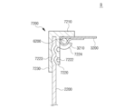
図3は、本発明の一実施形態による配管断熱構造体の分解断面図、図4および図5は、第1断熱カバー装置Aおよび第2断熱カバー装置Bを説明するための斜視図、図6~図9は、第1断熱カバー装置Aおよび第2断熱カバー装置Bを説明するための断面図である。図6は、第1断熱カバー装置Aのリング状加圧部を示す断面図、図7は、第1断熱カバー装置Aのクランピングフック結合部分を示す断面図、図8は、第2断熱カバー装置Bのリング状加圧部を示す断面図、図9は、第2断熱カバー装置Bのクランピングフック結合部分を示す断面図である。 Figure 3 is an exploded cross-sectional view of a piping insulation structure according to one embodiment of the present invention, Figures 4 and 5 are perspective views for explaining the first insulation cover device A and the second insulation cover device B, and Figures 6 to 9 are cross-sectional views for explaining the first insulation cover device A and the second insulation cover device B. Figure 6 is a cross-sectional view showing the ring-shaped pressure portion of the first insulation cover device A, Figure 7 is a cross-sectional view showing the clamping hook connection portion of the first insulation cover device A, Figure 8 is a cross-sectional view showing the ring-shaped pressure portion of the second insulation cover device B, and Figure 9 is a cross-sectional view showing the clamping hook connection portion of the second insulation cover device B.
図3~図9に示すように、本発明の一実施形態による配管断熱構造体は、高温高圧の蒸気や温水が流れる配管10を取り囲むように装着され、配管10の断熱性を高めるとともに外部衝撃による配管10の破損を防止することができるように構成される。図示してはいないが、配管10で発生する振動および騒音を減衰させることが可能な構造がさらに提供できる。
As shown in Figures 3 to 9, a pipe insulation structure according to one embodiment of the present invention is installed to surround a
本発明の配管断熱構造体は、エルボ配管、直管、フランジ用配管、バルブ用配管、T型配管などにその形状に合わせて変形して適用可能である。 The pipe insulation structure of the present invention can be modified to suit the shape of elbow pipes, straight pipes, flange pipes, valve pipes, T-shaped pipes, etc.
本実施形態において、配管断熱構造体は、配管10の幅方向の一側と他側を囲む半円筒状の第1断熱材1100及び第2断熱材1200と、前記第1断熱材1100と前記第2断熱材1200のそれぞれの外部表面を囲む第1断熱カバー装置A及び第2断熱カバー装置Bと、第1断熱カバー装置Aと第2断熱カバー装置Bとを結合させる締結ユニットと、を含む。図示してはいないが、配管10で発生した振動を吸収する防振手段がさらに設けられてもよい。
In this embodiment, the pipe insulation structure includes a semi-cylindrical
前記第1断熱材1100および第2断熱材1200は、多様な断熱材で構成でき、単一層構造または互いに異なる断熱材が互いに複数の層をなす複合層構造を有することができる。
The
前記第1断熱カバー装置A及び第2断熱カバー装置Bは、仕上げカバー2000と保護シート3000とを互いに結合させた構造を有し、前記仕上げカバー2000は、前記第1断熱カバー装置Aを構成する第1仕上げカバー2100と、前記第2断熱カバー装置Bを構成する第2仕上げカバー2200とに区分され、前記保護シート3000は、前記第1断熱カバー装置Aを構成する第1保護シート3100と、前記第2断熱カバー装置Bを構成する第2保護シート3200とに区分されることができる。
The first insulating cover device A and the second insulating cover device B have a structure in which a
具体的には、本実施形態による第1断熱カバー装置Aおよび第2断熱カバー装置Bは、前記第1断熱材1100と第2断熱材1200の外部表面の一部を覆う第1仕上げカバー2100および第2仕上げカバー2200と、前記第1断熱材1100と第2断熱材1200の外部表面のうち前記第1仕上げカバー2100または第2仕上げカバー2200によって覆われていない部位を覆う第1保護シート3100および第2保護シート3200と、を含む。
Specifically, the first insulating cover device A and the second insulating cover device B according to this embodiment include a
前記第1断熱カバー装置Aと第2断熱カバー装置Bとは、相互結合されたときに円筒状をなす一つの断熱カバー構造体となり、内部に備えられた断熱材を含む場合、前記配管断熱構造体を構成する。 The first insulating cover device A and the second insulating cover device B, when interconnected, form a single cylindrical insulating cover structure, and when they include an insulating material provided inside, constitute the piping insulating structure.
前記第1仕上げカバー2100と第2仕上げカバー2200は、外部衝撃に対する剛性を有しながらも製作時の便宜性を有するようにアルミニウムやアルミニウム合金などの軟質金属材質を有することができる。
The
前記第1断熱カバー装置Aおよび第2断熱カバー装置B、または前記第1仕上げカバー2100と第2仕上げカバー2200は、左右側に備えられたまま、長さ方向に沿ってアレイされた多数個の締結ユニットによって分離可能に結合される。本実施形態において、前記締結ユニットは、第2仕上げカバー2200に固定結合される締結フック5100と、第1仕上げカバー2100に回転可能な構造で結合される回転片5200と、一側が前記回転片5200に結合され、他側が締結フック5100に掛けられるように折り曲げられた締結リンク5300とから構成されることができる。
The first insulating cover device A and the second insulating cover device B, or the
また、第1保護シート3100と第2保護シート3200は、前記第1仕上げカバー2100または第2仕上げカバー2200によって覆われない第1断熱材1100と第2断熱材1200の外部表面、すなわち、第1断熱材1100及び第2断熱材1200の外周面ではなく、外部表面が外部に露出しないように第1断熱材1100と第2断熱材1200の一部の表面を囲むように配置される。
Furthermore, the first
このとき、第1保護シート3100と第2保護シート3200は、配管10から発生する熱によって損傷しないようにセラミック繊維などの不燃性織物で製作される。前記第1保護シート3100と第2保護シート3200は、織物で製作されることによりフレキシブルな特性を有するようになり、配管10の表面が不規則的であるか或いは突出部位が一部あるとしても、密着するように配管10を取り囲むことが可能である。
In this case, the first
前記第1保護シート3100と第2保護シート3200のそれぞれは、以下に説明される第1連結ソケット7100及び第2連結ソケット7200によって第1仕上げカバー2100及び第2仕上げカバー2200と連結される。フレキシブルな特性を有する第1保護シート3100と第2保護シート3200のそれぞれを第1連結ソケット7100および第2連結ソケット7200に安定的に結合するために、第1保護シート3100及び第2保護シート3200は、末端部分が折り畳まれて重なった後、裁縫されて第1及び第2輪部3110、3210が形成され、その第1及び第2輪部3110、3210には、一定強度を有する円形断面の第1及び第2鋼線6100、6200が長く挿設される。保護シート3100、3200は、金属で製作されるのではなく、フレキシブルな特性を有する軟性材質の織物で製作されるので、金属で製作される仕上げカバー2100、2200に直接結合される場合、前記保護シート3100、3200が前記仕上げカバー2100、2200から容易に剥離されるという問題が発生するおそれがある。したがって、保護シート3100、3200の末端部分がより堅固に仕上げカバー2100、2200と結合することができるように、前記鋼線6100、6200の挿入された前記輪部3100、3210を形成する。
The first
一方、前記仕上げカバー2000と保護シート3000との間に位置する断熱材1100または1200が一側に偏るか或いは偏らないように、すなわち、断熱材1100または1200の位置が一定に固定された状態を維持することができるように、前記仕上げカバー2000と保護シート3000によって形成された空間は、複数個のセル(cell)で構成されることができる。複数個のセルは、例えば、長さ方向の一端が保護シート3000に連結され、長さ方向の他端が断熱材1100または1200を貫通して仕上げカバー2000に連結される第1及び第2連結シート4100または4200によって区画されることができる。
Meanwhile, the space formed by the finishing
上述したように、本実施形態による第1断熱カバー装置Aおよび第2断熱カバー装置Bは、第1断熱材1100および第2断熱材1200の外部表面を覆う第1仕上げカバー2100および第2仕上げカバー2200と、第1断熱材1100および第2断熱材1200の外部表面のうち前記第1仕上げカバー2100または第2仕上げカバー2200によって覆われていない部位を覆う第1保護シート3100および第2保護シート3200と、第1保護シート3100及び第2保護シート3200のそれぞれを第1仕上げカバー2100及び第2仕上げカバー2200と連結するための第1連結ソケット7100及び第2連結ソケット7200と、を含む。
As described above, the first insulating cover device A and the second insulating cover device B according to this embodiment include a
前記第1連結ソケット7100は、アルミニウムやアルミニウム合金材料などの軟質金属材料を用いた押出成形によって形成できる。また、前記第1連結ソケット7100は、図6及び図7に示すように、第1水平板部7110と、第1水平板部7110から垂直方向に延びた第1内側垂直板部7120と、第1内側垂直板部7120と平行をなすように第1水平板部7110から垂直方向に延びた第1外側垂直板部7130とを一体に含む。
前記第1内側垂直板部7120と前記第1外側垂直板部7130との間には、第1仕上げカバー2100の挿入される第1挿入溝が形成される。第1仕上げカバー2100は、側端部が第1水平板部7110と接する深さまで第1挿入溝に完全に挿入されることが好ましい。
The first connecting
A first insertion groove into which the
前記第1挿入溝に挿入された第1仕上げカバー2100は、図6に示すように、第1内側垂直板部7120にリング状に加圧成形された複数個の第1リング状加圧部7122によって第1挿入溝にしっかりと固定される。複数個の第1リング状加圧部7122のそれぞれは、第1内側垂直板部7120にリング状断面のパンチ(punch)でプレス加工して形成されたものであり得る。具体的に説明すると、図13に示すように、底板8100にリング状断面のパンチ8200を設置し、前記パンチ8200の上に前記内側垂直板部7120の加圧部位が位置するようにした状態で、前記内側垂直板部7120の上側に位置する前記外側垂直板部7130の対応部位をプレス8300で加圧する方式で前記第1リング状加圧部7122を形成することが可能である。ここで、リング状断面の代わりに円形又はその他の断面形状のパンチが用いられることも考えられる。
The
前記第1リング状加圧部7122の深さは、前記パンチ8200が前記底板8100から突出した長さに対応するので、前記パンチ8200の突出長さを調節することにより、前記第1リング状加圧部7122の深さ調節が可能である。前記底板8100は、円滑な作業のために丸く突出する構造を有することができる。
The depth of the first ring-shaped
前記第1リング状加圧部7122のそれぞれは、第1仕上げカバー2100に向かって突出した形態を有し、前記第1仕上げカバー2100が第1リング状加圧部7122により押圧され、前記第1外側垂直板部7130は、前記第1仕上げカバー2100の被加圧部位によって押圧されることにより、すなわち、前記第1リング状加圧部7122を形成する圧力が前記第1仕上げカバー2100及び前記第1外側垂直板部7130に連鎖的に加えられることにより、前記第1仕上げカバー2100及び前記第1外側垂直板部7130のそれぞれには、対応する部位、すなわち、圧力が加えられる部位にリング状の溝7123が形成される。これにより、前記第1内側垂直板部7120、前記第1仕上げカバー2100及び前記第1外側垂直板部7130が互いに係合される。
Each of the first ring-shaped
上述したように、第1保護シート3100は、末端部分が折り畳まれて重なった後、裁縫されて第1輪部3110が形成され、その輪部3110には、一定強度を有する円形断面の第1鋼線6100が長く挿設される。
As described above, the end portion of the first
一方、第1保護シート3100は、図7に示すように、鋼線6000の挿入された第1輪部3110が第1水平板部7110と第1内側垂直板部7120との間のコーナーに置かれるように配置された状態で第1連結ソケット7100に固定される。第1連結ソケット7100は、第1保護シート3100を固定するために第1内側垂直板部7120から切り出されて曲げられたり巻き上げられたりして第1鋼線6100の挿入された第1輪部3110を囲む形態でクランプする複数個の第1クランピングフック7124を一体に含む。
Meanwhile, the first
複数個の第1クランピングフック7124のそれぞれを形成するために、互いに向かい合う一対の切開線を形成するように第1内側垂直板部7120を破る第1過程と、破られた部分、すなわち、一対の切開線の間で破られた部分をリング状に曲げたり巻き上げたりして、第1鋼線6100が挿入されている第1保護シート3100の第1輪部3110を囲む形態でクランプする第1クランピングフック7124を成形する第2過程が順次行われる。第1過程と第2過程が一つの装置によって一度に行われることもでき、別途の装置によってそれぞれ分けられて行われることもできる。
To form each of the plurality of first clamping hooks 7124, a first process is performed in which the first inner
また、第1連結ソケット7100は、第1水平板部7100の端部で第2連結ソケット7200の外面を覆うように、第1内側垂直板部7120及び第1外側垂直板部713の延長方向とは反対方向である垂直方向に延びた延長板部7140をさらに含む。このとき、延長板部7140と第2連結ソケット7200の外面との間にはパッキン7500が介在することができる。
The first connecting
一方、第2連結ソケット7200は、アルミニウムやアルミニウム合金材料などの軟質金属材料を用いた押出成形によって形成されるものであって、前述した第1連結ソケット7100と一つのセットをなすことができる。また、第2連結ソケット7200は、図8及び図9に示すように、第2水平板部7210と、前記第2水平板部7210から垂直方向に延びた第2内側垂直板部7220と、第2内側垂直板部7220と平行をなしながら第2水平板部7210から垂直方向に延びた第2外側垂直板部7230と、を一体に含む。
Meanwhile, the second connecting
第2内側垂直板部7220と第2外側垂直板部7230との間には、第2仕上げカバー2200の挿入される第2挿入溝が形成される。第2仕上げカバー2200は、側端部が第2水平板部7210と接する深さまで第2挿入溝に完全に挿入されることが好ましい。
A second insertion groove into which the
前記第2挿入溝に挿入された第2仕上げカバー2200は、図8に示すように、第2内側垂直板部7220にリング状に加圧成形された複数個の第2リング状加圧部7222によって第2挿入溝にしっかりと固定される。複数個の第2リング状加圧部7222のそれぞれは、第2内側垂直板部7220にリング状断面のパンチでプレス加工して形成されたものであり得る。前記第2リング状加圧部7222の形成方式は、前記第1リング状加圧部7122の形成方式と同様である。
The
前記第2リング状加圧部7222のそれぞれは、第2仕上げカバー2200に向かって突出した形態を有し、第2仕上げカバー2200が第2リング状加圧部7222により押圧され、前記第2外側垂直板部7230は、前記第2仕上げカバー2200の被加圧部位により押圧される。すなわち、前記第2リング状加圧部7222を形成する圧力が前記第2仕上げカバー2200及び前記第2外側垂直板部7230に連鎖的に加えられることにより、前記第2仕上げカバー2200及び前記第2外側垂直板部7230のそれぞれには、対応する部位、すなわち、圧力が加えられる部位にリング状の溝7223が形成される。これにより、前記第2内側垂直板部7220、前記第2仕上げカバー2200及び前記第1外側垂直板部7230が互いに係合される。
Each of the second ring-shaped
前記第2保護シート3200は、末端部分が折り畳まれて重なった後、裁縫されて第2輪部3210が形成され、その第2輪部3210には、一定強度を有する円形断面の第2鋼線6200が長く挿設される。
The end portion of the second
一方、第2保護シート3200は、図9に示すように、第2鋼線6200の挿入された第2輪部3210が第1水平板部7210と第2内側垂直板部7220との間のコーナーに置かれるように配置された状態で第2連結ソケット7200に固定される。第2連結ソケット7200は、第2保護シート3200を固定するために、第2内側垂直板部7220から切り出されて曲げられたり巻き上げられたりして、第2鋼線6200の挿入された第2輪部3210を囲む形態でクランプする複数個の第2クランピングフック7224を一体に含む。
Meanwhile, the second
複数個の第2クランピングフック7224のそれぞれを形成するために、互いに向かい合う一対の切開線を形成するように第2内側垂直板部7220を破る第1過程と、破られた部分、すなわち、一対の切開線の間で破られた部分をリング状に曲げたり巻き上げたりして、第2鋼線6200が挿入されている第2保護シート3200の輪部3210をクランプする第2クランピングフック7224を成形する第2過程が順次行われる。第1過程と第2過程が一つの装置によって一度に行われることもでき、別途の装置によってそれぞれ分けられて行われることもできる。
To form each of the plurality of second clamping hooks 7224, a first process is performed in which the second inner
前述したように、本発明は、連結ソケット7100または7200の内側垂直板部7120または7220と外側垂直板部7130または7230との間に挿入された仕上げカバー2100または2200が、内側垂直板部7120または7220をリング状断面のパンチを利用してプレス加工して形成された複数個のリング状加圧部7122または7222によって連結ソケット7100または7200と結合される。また、内側垂直板部7120または7220から切り出して曲げたり巻き上げたりして形成した複数個のクランピングフック7124、7224で鋼線6100または6200の挿入された輪部3210または3220をクランプすることにより、保護シート3100、3200を前記連結ソケット7100または7200に固定して結合するので、リベットまたはワッシャーの追加的な部品の省略が可能であり、そのリベットまたはワッシャーなどの部品を用いた複雑な結合作業が省略できる。
As described above, in the present invention, the finishing
次に、前述した配管断熱構造体の断熱カバー装置AまたはBの製造方法を説明する。
まず、水平板部7110または7210と、前記水平板部7110または7210から垂直方向に延びた内側垂直板部7120または7220と、前記水平板部7110または7210から垂直方向に延びて、前記内側垂直板部7120または7220との間に挿入溝を形成する外側垂直板部7130または7230と、を含む連結ソケット7100または7200を準備する。
Next, a method for manufacturing the heat insulating cover device A or B of the above-mentioned piping heat insulating structure will be described.
First, a connecting
次に、前述した仕上げカバー201000の端部を前記挿入溝に挿入し、前記挿入溝に前記仕上げカバー200の端部が挿入された状態で、前記内側垂直板部7120または7220に複数個の前記仕上げカバー2000を固定する複数個のリング状加圧部7122または7222をプレス加工によって形成することにより、前記仕上げカバー2000を連結ソケット7100または7200に固定結合する。
Next, the end of the finishing cover 201000 described above is inserted into the insertion groove, and with the end of the finishing cover 200 inserted into the insertion groove, a plurality of ring-shaped
また、保護シート3000を前記連結ソケット7100または7200に固定するために、前記保護シート3100または3200の末端を重ねて輪部3110または3210を形成した後、前記輪部3110または3210に前述した円形断面の鋼線6100または6200を挿入し、前記鋼線6100または6200の挿入された輪部3110または3210が前記水平板部7110または7210と前記内側垂直板部7120または7220との間のコーナーに置かれた状態で、前記内側垂直板部7120または7220を切り出して曲げたり巻き上げたりしたクランピングフック7124または7224で前記鋼線6100または6200の挿入された輪部3110または3210を囲むようにクランプすることにより、前記保護シート3000を連結ソケット7100または7200に固定結合する。
In addition, in order to fix the
一方、仕上げカバー2000は、図3に示すように、配管10を囲む断熱材1100、1200の外部表面を覆う構造で配管10の曲面に対応する曲面を有するように形成される。前記仕上げカバー2000は、複数のプレートと少なくとも一つの連結シャーシを用いて上述のリング状加圧部を形成する方式で複数のプレートと少なくとも一つの連結シャーシとを結合させて形成可能である。以下、図10~図13を参照して詳細に説明する。
Meanwhile, the finishing
図10は、前記仕上げカバーのうち、エルボ用配管に適用されるための仕上げカバーの概略図であり、図11は、図10の連結シャーシとプレートとの結合部分へのリング状加圧部の形成前と形成後の拡大図である。 Figure 10 is a schematic diagram of one of the finishing covers to be applied to an elbow pipe, and Figure 11 is an enlarged view of the ring-shaped pressure section before and after formation at the joint between the connecting chassis and the plate in Figure 10.
図10および図11に示すように、前記エルボ用配管の断熱カバー装置A、Bを構成する前記仕上げカバー2000は、複数のプレート2400と少なくとも一つの連結シャーシ2500とが前記エルボ用配管の曲面に対応するように組み立てられる。
As shown in Figures 10 and 11, the finishing
前記仕上げカバー2000は、少なくとも一つの連結シャーシ2500及び複数のプレート2400が組立又は結合される構造を有する。前記仕上げカバー2000の幅方向の端部は、図3を参照して説明したように、前記連結ソケット7100、7200を介して前記保護シート3000と結合される。前記仕上げカバー2000の長さ方向の端部も、必要に応じて、前記連結ソケット7100、7200を介して前記保護シート3000と結合される構造を有することができる。
The finishing
前記仕上げカバー2000をなす少なくとも一つの連結シャーシ2500と複数のプレート2400は、アルミニウムやアルミニウム合金などの軟質金属材質を有することができる。
At least one connecting
前記少なくとも一つの連結シャーシ2500の第1組立端部には第1シャーシ挿入溝2510が形成され、反対側の第2組立端部には第2シャーシ挿入溝2520が形成される。前記少なくとも一つの連結シャーシ2500は、断面がH字状を有することができ、第1組立端部と第2組立端部とが直線をなす平板形状を有することもでき、前記第1組立端部と前記第2組立端部とが互いに一定角度をなすように中間部分が曲げられた形状を有するか、或いは前記配管10の曲面に対応する曲面形状を有することができる。
A first
前記複数のプレート2400は、一定の長さを有するように備えられ、前記断熱カバー装置A、Bは、平板状、または配管10の曲面に対応する曲面状を有することができ、エルボ配管の曲面を囲む構造で形成されるために多様な幅を有することができる。
The
前記複数のプレート2400と前記少なくとも一つの連結シャーシ2500は、次の通りに組み立てられる。
The plurality of
図11の(a)に示すように、前記複数のプレート2400のうち、いずれか一つである第1プレート2400aの一端部が前記第1シャーシ挿入溝2510に挿入され、前記第1プレート2400aに隣接した第2プレート2400bの一端部が前記第2シャーシ挿入溝2520に挿入されるようにする。
As shown in FIG. 11(a), one end of a
この状態で、図11の(b)に示すように、前記少なくとも一つの連結シャーシ2500の内面(図3において、前記仕上げカバー2000が断熱材1100を囲む場合、断熱材1100と接触する面)から前記第1シャーシ挿入溝2510に向かってリング状に加圧成形される複数個の第3リング状加圧部2530を形成することにより、前記連結シャーシ2500と前記第1プレート2400aとが結合されるようにし、前記連結シャーシ2500の内面(図3において、前記仕上げカバー2000が断熱材1100を包む場合、断熱材1100と接触する面)から前記第2シャーシ挿入溝2520に向かってリング状に加圧成形される複数個の第4リング状加圧部2540を形成することにより、前記連結シャーシ2500と前記第2プレート2400bとが結合されるようにする。
In this state, as shown in FIG. 11(b), a plurality of third ring-shaped
このような方式で、前記複数のプレート2400と前記少なくとも一つの連結シャーシ2500とが前記配管10の曲面に対応して結合されて前記仕上げカバー2000を構成する。
In this manner, the
複数個の第3リング状加圧部2530及び複数個の第4リング状加圧部2540のそれぞれは、前記連結シャーシ2500の内面をリング状断面のパンチ(punch)でプレス加工して形成されたものであり得る。
Each of the plurality of third ring-shaped
具体的に説明すると、図13に示すように、底板8100にリング状断面のパンチ8200を設置し、前記パンチ8200上に前記連結シャーシ2500の内面の加圧部位が位置するようにした状態で、上側に位置する前記連結シャーシ2500の外面の対応部位をプレスで加圧する方式で前記複数の第3リング状加圧部2530及び複数個の第4リング状加圧部2540を形成することが可能である。ここで、リング状断面の代わりに円形又はその他の断面形状のパンチが用いられることも考えられる。
Specifically, as shown in FIG. 13, a
また、前記複数個の第3リング状加圧部2530及び複数個の第4リング状加圧部2540の深さは、前記パンチ8200が前記底板8100から突出した長さに対応するので、前記パンチ8200の突出長さを調節することにより、前記複数の第3リング状加圧部2530及び複数個の第4リング状加圧部2540の深さ調節が可能である。前記底板8100は、配管の曲面に対応する仕上げカバー2000の円滑な組立のために丸く突出する構造を有することができる。上述した図13のリング状加圧部を形成するための装置は、通常の技術者によく知られた多様な構造を有することができる。
In addition, the depth of the third ring-shaped
前記連結シャーシ2500の内面を加圧して形成された前記第3リング状加圧部2530及び前記第4リング状加圧部2540のそれぞれは、前記連結シャーシ2500のシャーシ挿入溝256、2520に挿入されたプレート2400a、2400bに向かって突出した形態を有し、シャーシ挿入溝256、2520に挿入されたプレート2400a、2400bの内側に形成される前記第3リング状加圧部2530及び前記第4リング状加圧部2540によって前記プレート2400a、2400bが押圧され、前記プレート2400a、2400bの被押圧部位によって前記プレート2400a、2400bの外側にある前記連結シャーシ2500が押圧されることにより、圧力が加えられる部位にリング状の溝2550が形成される。
The third ring-shaped
すなわち、前記第3リング状加圧部2530及び前記第4リング状加圧部2540を形成する圧力が前記連結シャーシ2500の内側、前記プレート2400a、2400b及び前記連結シャーシ2500の外側に連鎖的に加えられることにより、前記連結シャーシ2500及び前記プレート2400a、2400bのそれぞれには対応する部位、すなわち圧力が加えられる部位にリング状の溝2550が形成される。これにより、前記連結シャーシ2500と前記プレート2400a、2400bとが互いに係合される。
In other words, the pressure forming the third ring-shaped
これにより、前記連結シャーシ2500を媒介として互いに隣接した二つのプレート2400a、2400bが結合される。このような方式で複数のプレート2400と前記少なくとも一つの連結シャーシ2500を前記配管10の曲面に対応するように曲面状に結合すると、エルボ配管用仕上げカバー2000を構成することが可能である。
As a result, two
図12は、前記直管用配管の断熱カバー装置A、Bを構成する仕上げカバー2000を示すものである。図12に示すように、直管用仕上げカバー2000は、上述したエルボ配管用仕上げカバーの組立または結合方式をそのまま適用して実現可能である。
Figure 12 shows the finishing
その他にも、図10および図11を参照して説明した仕上げカバーの組立又は結合方式は、フランジ用配管、バルブ用配管、T型配管などにその形状に合わせて変形して適用可能であるのは明白である。 In addition, it is clear that the assembly or connection method of the finishing cover described with reference to Figures 10 and 11 can be modified and applied to flange piping, valve piping, T-shaped piping, etc. to suit their shapes.
上述したように、本発明によれば、配管を取り囲む断熱材を覆う仕上げカバー、保護シートと連結ソケットとを結合するにあたり、リベット等の追加的な要素なしで、簡便かつ速やかに結合することができるという利点がある。また、別途の締結部材なしで簡便かつ迅速に仕上げカバーを配管の曲面に対応するように組み立てることが可能である。 As described above, the present invention has the advantage that the finishing cover that covers the insulation surrounding the piping, the protective sheet and the connecting socket can be easily and quickly joined without the need for additional elements such as rivets. In addition, the finishing cover can be easily and quickly assembled to fit the curved surface of the piping without the need for separate fastening members.
以上、本発明を好適な実施形態を用いて詳細に説明したが、本発明の範囲は、特定の実施形態に限定されるものではなく、添付された特許請求の範囲によって解釈されるべきである。また、この技術分野における通常の知識を有する者であれば、本発明の範囲から逸脱することなく多くの修正と変形が可能である。 The present invention has been described in detail above using preferred embodiments, but the scope of the present invention should not be limited to specific embodiments, but should be interpreted by the scope of the appended claims. Furthermore, a person having ordinary knowledge in this technical field can make many modifications and variations without departing from the scope of the present invention.
Claims (10)
配管を囲む断熱材の外部表面の一部を覆う仕上げカバーと、
前記断熱材の外部表面のうち前記仕上げカバーによって覆われない部位を覆うように配置され、末端に鋼線の挿入された輪部を有する保護シートと、
前記仕上げカバーと前記保護シートとの間を連結するための連結ソケットと、を含み、
前記連結ソケットは、
水平板部と、
前記水平板部から垂直方向に延びた内側垂直板部と、
前記水平板部から垂直方向に延び、前記内側垂直板部との間に前記仕上げカバーが挿入される挿入溝を形成する外側垂直板部と、を含み、
前記挿入溝に挿入された前記仕上げカバーは、前記内側垂直板部にリング状に加圧成形される複数個のリング状加圧部によって前記連結ソケットと互いに結合され、
前記保護シートは、前記輪部が前記内側垂直板部から切り出されて曲げられたり巻き上げられたりする複数個のクランピングフックによって囲まれる形態でクランプされることにより、前記連結ソケットと互いに結合される
ことを特徴とする配管断熱構造体の断熱カバー装置。 A heat insulating cover device for a pipe insulation structure for insulating a pipe, comprising:
a finish cover covering a portion of the exterior surface of the insulation surrounding the piping;
A protective sheet is arranged to cover a portion of the outer surface of the insulation material that is not covered by the finishing cover, and has a loop portion with a steel wire inserted at its end;
a connection socket for connecting between the finishing cover and the protective sheet;
The connecting socket is
A horizontal plate portion;
An inner vertical plate portion extending vertically from the horizontal plate portion;
an outer vertical plate portion extending vertically from the horizontal plate portion and forming an insertion groove into which the finishing cover is inserted between the outer vertical plate portion and the inner vertical plate portion;
The finishing cover inserted into the insertion groove is coupled to the connecting socket by a plurality of ring-shaped pressurizing parts which are pressurized into a ring shape on the inner vertical plate part,
The protective sheet is connected to the connecting socket by being clamped in a manner that the loop portion is surrounded by a plurality of clamping hooks that are cut out from the inner vertical plate portion and bent or rolled up.
請求項1に記載の配管断熱構造体の断熱カバー装置。 2. The heat insulating cover device of claim 1, wherein the finishing cover and the connecting socket are made of soft metal material, and the protective sheet is made of a woven material.
前記仕上げカバー及び前記外側垂直板部のそれぞれには、前記リング状加圧部に押圧されてリング状の溝が形成されることにより、前記内側垂直板部、前記仕上げカバー及び前記外側垂直板部が互いに係合されるようにする
請求項2に記載の配管断熱構造体の断熱カバー装置。 the plurality of ring-shaped pressurizing portions are formed by pressing the inner vertical plate portion with a punch having a ring-shaped cross section,
3. An insulating cover device for a piping insulation structure as described in claim 2, wherein a ring-shaped groove is formed in each of the finishing cover and the outer vertical plate portion by pressing them against the ring-shaped pressure portion, thereby allowing the inner vertical plate portion, the finishing cover and the outer vertical plate portion to engage with each other.
請求項2に記載の配管断熱構造体の断熱カバー装置。 3. The insulating cover device of a piping insulation structure as described in claim 2, wherein the protective sheet is connected to the connecting socket by clamping the clamping hook, which is cut out from the inner vertical plate portion and bent or rolled up, to surround the ring portion with the ring portion placed at the corner between the horizontal plate portion and the inner vertical plate portion.
第1組立端部には第1シャーシ挿入溝が形成され、第2組立端部には第2シャーシ挿入溝が形成された軟質金属材質の少なくとも一つの連結シャーシと、
軟質金属材質の複数のプレートと、を備え、
前記複数のプレートのうちのいずれか一つである第1プレートの一端部が前記第1シャーシ挿入溝に挿入され、前記第1プレートに隣接した第2プレートの一端部が前記第2シャーシ挿入溝に挿入されるようにした状態で、
前記連結シャーシの内面から前記第1シャーシ挿入溝に向かってリング状に加圧成形される複数個のリング状加圧部によって前記連結シャーシと前記第1プレートとが結合され、前記連結シャーシの内面から前記第2シャーシ挿入溝に向かってリング状に加圧成形される複数個のリング状加圧部によって前記連結シャーシと前記第2プレートとが結合されるようにする方式で、
前記複数のプレートと前記少なくとも一つの連結シャーシが前記配管の曲面に対応して結合された構造を有する
請求項1に記載の廃館断熱構造体の断熱カバー装置。 The finishing cover is
At least one connecting chassis made of a soft metal material, the connecting chassis having a first chassis insertion groove formed at a first assembly end and a second chassis insertion groove formed at a second assembly end;
a plurality of plates made of a soft metal material;
one end of a first plate, which is one of the plurality of plates, is inserted into the first chassis insertion groove, and one end of a second plate adjacent to the first plate is inserted into the second chassis insertion groove,
The connecting chassis and the first plate are joined by a plurality of ring-shaped pressurizing parts which are pressurized from an inner surface of the connecting chassis toward the first chassis insertion groove in a ring shape, and the connecting chassis and the second plate are joined by a plurality of ring-shaped pressurizing parts which are pressurized from an inner surface of the connecting chassis toward the second chassis insertion groove in a ring shape,
The insulation cover device for an abandoned building insulation structure as described in claim 1, wherein the multiple plates and the at least one connecting chassis have a structure in which they are connected to correspond to the curved surface of the piping.
請求項5に記載の配管断熱構造体の断熱カバー装置。
The at least one connecting chassis has a flat plate shape with an "H"-shaped cross section, or has a shape in which the middle portion is bent or curved so that the first assembly end and the second assembly end form a certain angle with each other.
請求項5に記載の配管断熱構造体の断熱カバー装置。 The at least one connecting chassis and the plate inserted into the at least one connecting chassis are pressed against the ring-shaped pressure portion to form a ring-shaped groove, thereby engaging the at least one connecting chassis and the plate with each other.
配管を囲む断熱材の外部表面を覆う仕上げカバーと、前記断熱材の外部表面のうち、前記仕上げカバーによって覆われない部位を覆うように配置され、末端に鋼線の挿入された輪部を有する保護シートと、を準備し、前記仕上げカバーと前記保護シートとを連結するために、水平板部と、前記水平板部から垂直方向に延びた内側垂直板部と、前記水平板部から垂直方向に延び、前記内側垂直板部との間に挿入溝を形成する外側垂直板部とを一体に含む連結ソケットを準備するステップと、
前記仕上げカバーの端部を前記挿入溝に挿入し、前記挿入溝に前記仕上げカバーの端部が挿入された状態で、前記内側垂直板部に複数個のリング状加圧部を形成して、前記仕上げカバーと前記連結ソケットとを結合するステップと、
前記保護シートの輪部が前記連結ソケットの前記水平板部と前記内側垂直板部との間のコーナーに置かれた状態で、前記内側垂直板部を切り出して曲げたり巻き上げたりしたクランピングフックで、前記鋼線の挿入された輪部を囲む形態でクランプすることにより、前記保護シートと前記連結ソケットとを結合するステップと、を備える
ことを特徴とする配管断熱構造体の断熱カバー装置の製造方法。 A method for manufacturing an insulating cover device for a pipe insulating structure, comprising:
A step of preparing a finishing cover that covers the outer surface of the insulation surrounding the piping, and a protective sheet that is arranged to cover the portion of the outer surface of the insulation that is not covered by the finishing cover and has a ring portion with a steel wire inserted at its end, and a connecting socket that integrally includes a horizontal plate portion, an inner vertical plate portion extending vertically from the horizontal plate portion, and an outer vertical plate portion extending vertically from the horizontal plate portion and forming an insertion groove between the inner vertical plate portion and the horizontal plate portion, in order to connect the finishing cover and the protective sheet;
inserting an end of the finishing cover into the insertion groove, and forming a plurality of ring-shaped pressure portions on the inner vertical plate portion while the end of the finishing cover is inserted into the insertion groove, thereby coupling the finishing cover and the connecting socket;
and a step of connecting the protective sheet and the connecting socket by placing the ring portion of the protective sheet at the corner between the horizontal plate portion and the inner vertical plate portion of the connecting socket, and clamping the inner vertical plate portion in a manner that surrounds the ring portion into which the steel wire is inserted with a clamping hook that is cut out, bent, or rolled up.
前記仕上げカバー及び前記外側垂直板部のそれぞれには、前記リング状加圧部に押圧されてリング状の溝が形成されることにより、前記内側垂直板部、前記仕上げカバー及び前記外側垂直板部が互いに係合されるようにする
請求項8に記載の配管断熱構造体の断熱カバー装置の製造方法。 The plurality of ring-shaped pressurizing portions are formed by pressing the inner vertical plate portion with a punch having a ring-shaped cross section,
A method for manufacturing an insulating cover device for a piping insulation structure as described in claim 8, wherein a ring-shaped groove is formed in each of the finishing cover and the outer vertical plate portion by pressing them against the ring-shaped pressure portion, thereby allowing the inner vertical plate portion, the finishing cover and the outer vertical plate portion to engage with each other.
第1端部には第1シャーシ挿入溝が形成され、第2端部には第2シャーシ挿入溝が形成された軟質金属材質の少なくとも一つの連結シャーシと、
軟質金属材質の複数のプレートと、を備え、
前記複数のプレートのうちいずれか一つである第1プレートの一端部が前記第1シャーシ挿入溝に挿入され、前記第1プレートに隣接した第2プレートの一端部が前記第2シャーシ挿入溝に挿入されるようにした状態で、
前記連結シャーシの内面から前記第1シャーシ挿入溝に向かってリング状に加圧成形される複数個のリング状加圧部によって前記連結シャーシと前記第1プレートとが結合され、前記連結シャーシの内面から前記第2シャーシ挿入溝に向かってリング状に加圧成形される複数個のリング状加圧部によって前記連結シャーシと前記第2プレートとが結合されるようにする方式で、
前記複数のプレートと前記少なくとも一つの連結シャーシとが前記配管の曲面に対応して結合された構造を有する
請求項8に記載の配管断熱構造体の断熱カバー装置の製造方法。 The finishing cover is
At least one connecting chassis made of a soft metal material, the connecting chassis having a first chassis insertion groove formed at a first end and a second chassis insertion groove formed at a second end;
a plurality of plates made of a soft metal material;
one end of a first plate, which is one of the plurality of plates, is inserted into the first chassis insertion groove, and one end of a second plate adjacent to the first plate is inserted into the second chassis insertion groove,
The connecting chassis and the first plate are joined by a plurality of ring-shaped pressurizing parts which are pressurized from an inner surface of the connecting chassis toward the first chassis insertion groove in a ring shape, and the connecting chassis and the second plate are joined by a plurality of ring-shaped pressurizing parts which are pressurized from an inner surface of the connecting chassis toward the second chassis insertion groove in a ring shape,
The method for manufacturing an insulating cover device for a piping insulating structure according to claim 8, wherein the plurality of plates and the at least one connecting chassis are coupled to each other in correspondence with a curved surface of the piping.
Applications Claiming Priority (3)
| Application Number | Priority Date | Filing Date | Title |
|---|---|---|---|
| KR10-2021-0152230 | 2021-11-08 | ||
| KR1020210152230A KR102470040B1 (en) | 2021-11-08 | 2021-11-08 | Insulation cover device in piping heat insulating structure and method for manufacturing the same |
| PCT/KR2021/017376 WO2023080315A1 (en) | 2021-11-08 | 2021-11-24 | Insulating cover device of pipe-insulating structure, and manufacturing method therefor |
Publications (2)
| Publication Number | Publication Date |
|---|---|
| JP2024537578A JP2024537578A (en) | 2024-10-11 |
| JP7588926B2 true JP7588926B2 (en) | 2024-11-25 |
Family
ID=84236742
Family Applications (1)
| Application Number | Title | Priority Date | Filing Date |
|---|---|---|---|
| JP2024526736A Active JP7588926B2 (en) | 2021-11-08 | 2021-11-24 | Heat insulating cover device for piping heat insulating structure and its manufacturing method |
Country Status (5)
| Country | Link |
|---|---|
| US (1) | US12117119B1 (en) |
| EP (1) | EP4431784A4 (en) |
| JP (1) | JP7588926B2 (en) |
| KR (1) | KR102470040B1 (en) |
| WO (1) | WO2023080315A1 (en) |
Families Citing this family (2)
| Publication number | Priority date | Publication date | Assignee | Title |
|---|---|---|---|---|
| KR102659100B1 (en) * | 2023-08-08 | 2024-04-22 | 김국수 | Insulation device for pipe with improved structural strength |
| CN118623144B (en) * | 2024-08-14 | 2024-11-12 | 兴化市热华能源有限公司 | A heat preservation device for heat pipe |
Citations (2)
| Publication number | Priority date | Publication date | Assignee | Title |
|---|---|---|---|---|
| JP2020511607A (en) | 2017-03-21 | 2020-04-16 | ジョーウン−デコ カンパニー リミテッドJoeun−Deco Co.,Ltd | Finishing panel fixing device |
| JP2020516821A (en) | 2017-04-07 | 2020-06-11 | パブリック ジョイント ストック カンパニー マシン−ビルディング プラント“ジオ ポドリスク” | Reinforced removable insulation |
Family Cites Families (13)
| Publication number | Priority date | Publication date | Assignee | Title |
|---|---|---|---|---|
| JPS3810589Y1 (en) * | 1959-06-23 | 1963-05-31 | ||
| US3559694A (en) * | 1969-04-14 | 1971-02-02 | Associated Insulation Of Calif | Removable insulated fitting for pipe joints |
| US3886981A (en) * | 1971-11-08 | 1975-06-03 | Atlantic Richfield Co | Pipeline insulation means |
| US3818949A (en) * | 1973-02-05 | 1974-06-25 | Transco Inc | Removable insulated pipe jacket |
| JPS6028692U (en) * | 1983-08-03 | 1985-02-26 | 鐘淵化学工業株式会社 | tube body |
| JPH02109717U (en) * | 1989-02-21 | 1990-09-03 | ||
| KR200207806Y1 (en) * | 2000-07-06 | 2000-12-15 | 이종문 | A elbow duct for pipe insulation |
| JP2002048295A (en) * | 2000-08-03 | 2002-02-15 | Inoac Corp | Piping cover member |
| KR20040081397A (en) * | 2004-08-28 | 2004-09-21 | 노현우 | the keeping warm cover for distributor of boiler |
| JP5188692B2 (en) * | 2006-10-05 | 2013-04-24 | 株式会社久米設計 | Folding duct and mounting method of the folding duct |
| KR101727682B1 (en) * | 2015-12-08 | 2017-04-19 | (주)동인엔지니어링 | Pipe heating cover |
| KR101820450B1 (en) | 2017-06-12 | 2018-01-22 | (주)동인엔지니어링 | Pipe insulation apparatus with vibration prevention function |
| KR101889443B1 (en) * | 2018-01-05 | 2018-08-17 | (주)동인엔지니어링 | Pipe insulation apparatus |
-
2021
- 2021-11-08 KR KR1020210152230A patent/KR102470040B1/en active Active
- 2021-11-24 US US18/702,483 patent/US12117119B1/en active Active
- 2021-11-24 JP JP2024526736A patent/JP7588926B2/en active Active
- 2021-11-24 WO PCT/KR2021/017376 patent/WO2023080315A1/en not_active Ceased
- 2021-11-24 EP EP21963415.1A patent/EP4431784A4/en active Pending
Patent Citations (2)
| Publication number | Priority date | Publication date | Assignee | Title |
|---|---|---|---|---|
| JP2020511607A (en) | 2017-03-21 | 2020-04-16 | ジョーウン−デコ カンパニー リミテッドJoeun−Deco Co.,Ltd | Finishing panel fixing device |
| JP2020516821A (en) | 2017-04-07 | 2020-06-11 | パブリック ジョイント ストック カンパニー マシン−ビルディング プラント“ジオ ポドリスク” | Reinforced removable insulation |
Also Published As
| Publication number | Publication date |
|---|---|
| WO2023080315A1 (en) | 2023-05-11 |
| EP4431784A4 (en) | 2025-09-10 |
| EP4431784A1 (en) | 2024-09-18 |
| KR102470040B1 (en) | 2022-11-23 |
| US12117119B1 (en) | 2024-10-15 |
| JP2024537578A (en) | 2024-10-11 |
| US20240328566A1 (en) | 2024-10-03 |
Similar Documents
| Publication | Publication Date | Title |
|---|---|---|
| JP7588926B2 (en) | Heat insulating cover device for piping heat insulating structure and its manufacturing method | |
| US5813438A (en) | Braided conduit and method of making a braided conduit | |
| US9958106B2 (en) | Insulating material protective cover for valve unit | |
| US4724293A (en) | Method of making a pressure vessel | |
| JP6723364B2 (en) | Temporary scaffolding board fixing device for scaffolding | |
| KR101187548B1 (en) | Wire braid hose expansion joint | |
| JPH0914545A (en) | Pipe joint and packing | |
| KR20140049653A (en) | Pipe connection device | |
| KR100822219B1 (en) | Tube coupler | |
| CN217683747U (en) | Connecting device for plastic-coated steel pipe | |
| KR101889443B1 (en) | Pipe insulation apparatus | |
| KR100597567B1 (en) | Pocket Flange in Duct | |
| KR101339856B1 (en) | Method for manufacturing expansion joint | |
| KR101636217B1 (en) | Elbow pipe manufacturing method and a manufacturing apparatus | |
| JP2010090672A (en) | External facing material attaching member, attaching structure for the same, attaching method for the same, and construction method of external facing structure | |
| KR102659100B1 (en) | Insulation device for pipe with improved structural strength | |
| KR102446724B1 (en) | Clamping hook forming device for connection sockets for pipe insulation structures | |
| KR102880001B1 (en) | air conditioner pipe | |
| CN102278564A (en) | Flexible pipe | |
| KR20230095360A (en) | Composite column and manufacturing method thereof | |
| KR20170100895A (en) | Added huraekssibeul and the manufacturing method for high pressure for high pressure added huraekssibeul | |
| KR101890284B1 (en) | Valve unit insulation apparatus | |
| RU234620U1 (en) | PIPELINE SEALING AND HERMETIZATION SYSTEM | |
| KR102766507B1 (en) | Pipe Clamping Device And Installation method for Pipe Clamping Device | |
| JP2002161708A (en) | Piping pressure sealing method |
Legal Events
| Date | Code | Title | Description |
|---|---|---|---|
| A521 | Request for written amendment filed |
Free format text: JAPANESE INTERMEDIATE CODE: A523 Effective date: 20240502 |
|
| A621 | Written request for application examination |
Free format text: JAPANESE INTERMEDIATE CODE: A621 Effective date: 20240502 |
|
| A871 | Explanation of circumstances concerning accelerated examination |
Free format text: JAPANESE INTERMEDIATE CODE: A871 Effective date: 20240502 |
|
| TRDD | Decision of grant or rejection written | ||
| A01 | Written decision to grant a patent or to grant a registration (utility model) |
Free format text: JAPANESE INTERMEDIATE CODE: A01 Effective date: 20241029 |
|
| A61 | First payment of annual fees (during grant procedure) |
Free format text: JAPANESE INTERMEDIATE CODE: A61 Effective date: 20241106 |
|
| R150 | Certificate of patent or registration of utility model |
Ref document number: 7588926 Country of ref document: JP Free format text: JAPANESE INTERMEDIATE CODE: R150 |