JP6723364B2 - Temporary scaffolding board fixing device for scaffolding - Google Patents
Temporary scaffolding board fixing device for scaffolding Download PDFInfo
- Publication number
- JP6723364B2 JP6723364B2 JP2018535890A JP2018535890A JP6723364B2 JP 6723364 B2 JP6723364 B2 JP 6723364B2 JP 2018535890 A JP2018535890 A JP 2018535890A JP 2018535890 A JP2018535890 A JP 2018535890A JP 6723364 B2 JP6723364 B2 JP 6723364B2
- Authority
- JP
- Japan
- Prior art keywords
- scaffolding
- clamp
- steel pipe
- temporary
- pin
- Prior art date
- Legal status (The legal status is an assumption and is not a legal conclusion. Google has not performed a legal analysis and makes no representation as to the accuracy of the status listed.)
- Expired - Fee Related
Links
- 229910000831 Steel Inorganic materials 0.000 claims description 38
- 239000010959 steel Substances 0.000 claims description 38
- 230000008878 coupling Effects 0.000 claims description 20
- 238000010168 coupling process Methods 0.000 claims description 20
- 238000005859 coupling reaction Methods 0.000 claims description 20
- 230000000149 penetrating effect Effects 0.000 claims description 7
- 238000009434 installation Methods 0.000 description 6
- 239000000463 material Substances 0.000 description 4
- 238000000034 method Methods 0.000 description 4
- 238000007667 floating Methods 0.000 description 3
- 238000004519 manufacturing process Methods 0.000 description 3
- 125000006850 spacer group Chemical group 0.000 description 3
- 239000000470 constituent Substances 0.000 description 2
- 238000010276 construction Methods 0.000 description 2
- 238000010586 diagram Methods 0.000 description 2
- 230000000694 effects Effects 0.000 description 2
- 238000007796 conventional method Methods 0.000 description 1
- 238000005516 engineering process Methods 0.000 description 1
Images


Classifications
-
- E—FIXED CONSTRUCTIONS
- E04—BUILDING
- E04G—SCAFFOLDING; FORMS; SHUTTERING; BUILDING IMPLEMENTS OR AIDS, OR THEIR USE; HANDLING BUILDING MATERIALS ON THE SITE; REPAIRING, BREAKING-UP OR OTHER WORK ON EXISTING BUILDINGS
- E04G7/00—Connections between parts of the scaffold
- E04G7/02—Connections between parts of the scaffold with separate coupling elements
- E04G7/28—Clips or connections for securing boards
-
- E—FIXED CONSTRUCTIONS
- E04—BUILDING
- E04G—SCAFFOLDING; FORMS; SHUTTERING; BUILDING IMPLEMENTS OR AIDS, OR THEIR USE; HANDLING BUILDING MATERIALS ON THE SITE; REPAIRING, BREAKING-UP OR OTHER WORK ON EXISTING BUILDINGS
- E04G5/00—Component parts or accessories for scaffolds
- E04G5/08—Scaffold boards or planks
-
- E—FIXED CONSTRUCTIONS
- E04—BUILDING
- E04G—SCAFFOLDING; FORMS; SHUTTERING; BUILDING IMPLEMENTS OR AIDS, OR THEIR USE; HANDLING BUILDING MATERIALS ON THE SITE; REPAIRING, BREAKING-UP OR OTHER WORK ON EXISTING BUILDINGS
- E04G7/00—Connections between parts of the scaffold
- E04G7/02—Connections between parts of the scaffold with separate coupling elements
- E04G7/26—Connections between parts of the scaffold with separate coupling elements for use with specially-shaped scaffold members
Description
本発明は足場用仮設足場板固定装置に関し、さらに詳しくは高所作業のために設置された足場に作業空間及び歩行路の確保のために設置される仮設足場板を堅固かつ迅速にクランプ可能とすることにより、作業の安定性と効率性を高めることができる足場用仮設足場板固定装置に関する。 The present invention relates to a temporary scaffolding board fixing device for scaffolding, and more specifically, it is possible to firmly and quickly clamp a temporary scaffolding board installed for securing a working space and a walkway on a scaffolding installed for work at high places. By doing so, the present invention relates to a temporary scaffolding plate fixing device for scaffolding, which can enhance the stability and efficiency of work.
一般に、建築や建設及び造船など、産業現場で様々な装備と資材を高所へ運搬して作業するための手段として仮設構造物である足場用鋼管を設置した後、その鋼管に支持されるようにパネル形状に製作された作業足場板を据え置く方法が一般化されている。 Generally, after installing a steel pipe for scaffolding, which is a temporary structure, as a means for transporting and working various equipment and materials to high places at industrial sites such as construction, construction and shipbuilding, it is supposed to be supported by the steel pipe. The method of laying down the panel-shaped work scaffolding plate has been generalized.
前記鋼管足場に設置された作業足場は作業の生産性に直接影響を及ぼす構造物であって、性能検定試験に合格した鋼材を素材として様々な規格で製作されており、特に造船分野と高度の高い海洋プラントを製作する時に用いられる作業足場板は、安全基準に対する標準化を通じて安全文化を革新している。 The work scaffold installed on the steel pipe scaffold is a structure that directly affects the productivity of work, and is manufactured in various standards using steel materials that have passed the performance certification test as materials, especially in the field of shipbuilding and The work scaffolding plates used to build tall marine plants are revolutionizing safety culture through standardization to safety standards.
足場を構成している作業足場板は、複数の鋼管に載置された状態で固定設置され、この時、作業足場板を鋼管に固定するために両側部材を針金で縛ったが、作業性に劣る問題点により近年では様々な種類の専用固定器具を用いている傾向である。 The work scaffolding plate that constitutes the scaffolding is fixedly installed in a state of being placed on multiple steel pipes.At this time, both side members were tied with wires to fix the work scaffolding plate to the steel pipes. Due to its inferior problems, in recent years there is a tendency to use various types of dedicated fixing devices.
従来の韓国登録特許第10−1016274号公報は、一対のプレートを突き合せた状態で必要に応じて相互組み立てることができるようにした足場板において、前記プレートの突き合せた部分の空間に結合可能な形状で内部に凹溝部が形成され、底面に結合孔が形成されたブラケットと、前記ブラケットの結合孔を通じてパイプをクランプすることができるクランプの上端にネジ棒を形成した状態で結合した後、上部に貫通孔を形成した円柱形状の固定ピンを横にして結合し、前記固定ピンには偏心孔が形成されたクランプハンドルを結合して作動孔を通じてクランプハンドルを作動することにより、偏心孔によりクランプが囲んでいるパイプを引くようになって、各プレートが堅固に固定されることができるように構成した足場板用固定冶具が提案されている。 According to the conventional Korean Patent Registration No. 10-1016274, a scaffolding plate is constructed such that a pair of plates can be assembled to each other as needed, and the scaffolding plate can be coupled to the space of the parts where the plates are butted. After forming a concave groove in the shape of a bracket, and a bracket having a coupling hole formed on the bottom surface, and a screw rod formed at the upper end of the clamp that can clamp the pipe through the coupling hole of the bracket, after coupling, A cylindrical fixing pin with a through hole formed in the upper part is connected sideways, and a clamp handle having an eccentric hole is connected to the fixing pin, and the clamp handle is operated through the operation hole. There has been proposed a scaffolding plate fixing jig configured so that each plate can be firmly fixed by pulling a pipe surrounded by a clamp.
しかし、前記従来の技術はパイプを囲むクランプが一つのフック(hook)となっているため、クランプハンドルを作動させてパイプを引く場合、フックの接触された部位のみに力が加わることにより、固定力を発揮する部位が制限され、堅固性と安全性に劣るという問題点があった。 However, since the clamp surrounding the pipe is one hook in the above conventional technique, when the clamp handle is operated to pull the pipe, a force is applied only to the contacted portion of the hook to fix the hook. There is a problem that the part that exerts the power is limited and the robustness and safety are poor.
特に、クランプハンドルを作動させて、その偏心孔に結合された固定ピンを起点としてパイプを囲んでいるクランプを上方へ引くことになると、一つのフック構造となっているクランプに偏心応力が加わることにより、応力が集中する部位が弱くなってクランプに変形や損傷が頻繁に発生し、耐久性が失われることはもちろん、鋼管からクランプが離脱されて安全性が欠如するという問題点もあった。 In particular, when the clamp handle is actuated and the clamp surrounding the pipe is pulled upward from the fixing pin connected to the eccentric hole as the starting point, eccentric stress is applied to the clamp with one hook structure. As a result, the portion where stress is concentrated weakens, the clamp is frequently deformed or damaged, and durability is lost. In addition, the clamp is disengaged from the steel pipe, resulting in lack of safety.
本発明は、前記のような従来の鋼管足場に足場板を固定するための装置の問題点に鑑みて発明したものであって、その目的は、高所作業のために設置された鋼管素材の足場に作業空間及び歩行路を確保するための足場板を設置する足場板の固定作業を堅固かつ迅速に行うことができる足場用仮設足場板固定装置を提供することにある。 The present invention has been made in view of the problems of the device for fixing the scaffolding plate to the conventional steel pipe scaffolding as described above, and its object is to provide a steel pipe material installed for aerial work. (EN) Provided is a temporary scaffolding plate fixing device for scaffolding, which can firmly and quickly fix the scaffolding plate for installing a scaffolding plate for securing a work space and a walking path on the scaffolding.
本発明が解決しようとする課題は前述の課題に制限されず、言及されないまた他の課題は以下の記載により本発明が属する技術分野において通常の知識を有する者にとって明確に理解されるべきである。 The problem to be solved by the present invention is not limited to the above-mentioned problems, and other problems not mentioned are to be clearly understood by those having ordinary knowledge in the technical field to which the present invention belongs. ..
前述した本発明の目的によって、鋼管足場の上部に安着される仮設足場板を固定させるための鋼管足場用仮設足場板固定装置であって、前記仮設足場板の上側の端に一部が安着されたまま前記仮設足場板をクランプする足場板クランプと、前記鋼管足場の外周を部分的に囲むようにクランプする円弧状の鋼管足場クランプと、前記足場板クランプと鋼管足場クランプとを連結する連結部材とで構成され、前記連結部材は、前記足場板クランプと鋼管足場クランプとの間に配置され、上部ピン孔及び下部ピン孔が形成された連結ブラケットと、前記上部ピン孔に嵌合され、貫通孔が形成された結束ピンと、前記足場板クランプを上部から貫通して前記結束ピンの貫通孔にネジ締結される締結ボルトと、前記足場板クランプと結束ピンとの間に介在される弾性部材と、前記下部ピン孔及び前記鋼管足場クランプの上端を貫通して連結ブラケットと鋼管足場クランプとを結合する結合ピンとで構成されることをさらに含む、足場用仮設足場板固定装置が提供される。 According to the above-mentioned object of the present invention, there is provided a temporary scaffolding plate fixing device for a steel pipe scaffolding for fixing a temporary scaffolding plate to be seated on an upper part of the steel pipe scaffolding, wherein a part of the temporary scaffolding plate has an upper end. A scaffolding plate clamp that clamps the temporary scaffolding plate while being worn, an arc-shaped steel pipe scaffolding clamp that clamps so as to partially surround the outer circumference of the steel pipe scaffolding, and the scaffolding plate clamp and the steel pipe scaffolding clamp are connected. And a coupling bracket, which is disposed between the scaffolding plate clamp and the steel pipe scaffolding clamp, has a top pin hole and a bottom pin hole formed therein, and is fitted into the top pin hole. A binding pin having a through hole, a fastening bolt penetrating the scaffolding plate clamp from above and screwed into the through hole of the binding pin, and an elastic member interposed between the scaffolding plate clamp and the binding pin. A temporary scaffolding plate fixing device for scaffolding is further provided, which further comprises: and a connecting pin that penetrates the lower pin hole and the upper end of the steel pipe scaffolding clamp to connect the connecting bracket and the steel pipe scaffolding clamp.
また、本発明の目的によって、足場の上部に安着される仮設足場板を固定させるための足場用仮設足場板固定装置であって、前記仮設足場板の上側の端に一部が安着されたまま前記仮設足場板をクランプする足場板クランプと、前記足場の水平端部をクランプするC型の足場クランプと、前記足場板クランプと足場クランプとを連結する連結部材とで構成され、前記連結部材は前記足場板クランプと足場クランプとの間に配置され、上部ピン孔及び下部ピン孔が形成された連結ブラケットと、前記上部ピン孔に嵌合され、貫通孔が形成された結束ピンと、前記足場板クランプを上部から貫通して前記結束ピンの貫通孔にネジ締結される締結ボルトと、前記足場板クランプと結束ピンとの間に介在される弾性部材と、前記下部ピン孔及び前記足場クランプの上端を貫通して連結ブラケットと足場クランプとを結合する結合ピンとで構成されていることをさらに含む、足場用仮設足場板固定装置が提供されることができる。 Further, according to the object of the present invention, there is provided a temporary scaffolding plate fixing device for scaffolding for fixing a temporary scaffolding plate to be seated on an upper part of the scaffolding, wherein a part of the temporary scaffolding plate is seated on an upper end of the temporary scaffolding plate. A scaffolding plate clamp that clamps the temporary scaffolding plate, a C-shaped scaffolding clamp that clamps the horizontal end of the scaffolding, and a connecting member that connects the scaffolding plate clamp and the scaffolding clamp. The member is disposed between the scaffolding plate clamp and the scaffolding clamp, a connecting bracket having an upper pin hole and a lower pin hole, a binding pin fitted in the upper pin hole and having a through hole, A fastening bolt that penetrates the scaffolding plate clamp from above and is screwed into the through hole of the binding pin, an elastic member interposed between the scaffolding plate clamp and the binding pin, the lower pin hole and the scaffolding clamp. A temporary scaffolding plate fixing device for scaffolding may further be provided, which further comprises a connecting pin penetrating the upper end and connecting the connecting bracket and the scaffolding clamp.
また、本発明の目的によって、足場の上部に安着される仮設足場を固定させるための足場用仮設足場板固定装置であって、前記仮設足場板の上側の端に一部が安着されたまま前記仮設足場板をクランプする足場板クランプと、前記足場の垂直端部をクランプする足場クランプと、前記足場板クランプと足場クランプとを連結する連結部材とで構成され、前記連結部材は前記足場板クランプと足場クランプとの間に配置され、上部ピン孔及び下部ピン孔が形成された連結ブラケットと、前記上部ピン孔に嵌合され、貫通孔が形成された結束ピンと、前記足場板クランプを上部から貫通して前記結束ピンの貫通孔にネジ締結される締結ボルトと、前記足場板クランプと結束ピンとの間に介在される弾性部材と、前記下部ピン孔及び前記足場クランプの上端を貫通して連結ブラケットと足場クランプとを結合する結合ピンとで構成され、前記足場クランプは、前記結合ピンにより前記連結ブラケットの下部に結合され、下端に前記足場の垂直端部が凹入される凹入溝の形成されたクランプハウジングと、前記クランプハウジングの内部の両側に配置され、前記結合ピンにより前記クランプハウジングに上部がピン結合されて結合ピンを中心として相互反対方向にリンク回転する一対のリンク節と、前記各リンク節の下端にピン結合されたまま前記リンク節のリンク回転によって前記クランプハウジングの凹入溝へ凹入される足場の垂直端部を両方で把持する一対のクランパーとで構成されることをさらに含む、足場用仮設足場板固定装置が提供されることができる。 Further, according to the object of the present invention, there is provided a temporary scaffold plate fixing device for a scaffold for fixing a temporary scaffold which is seated on an upper part of the scaffold, wherein a part of the temporary scaffold plate is seated at an upper end of the temporary scaffold plate. The scaffolding plate clamp that clamps the temporary scaffolding plate, the scaffolding clamp that clamps the vertical end of the scaffolding, and the connecting member that connects the scaffolding plate clamp and the scaffolding clamp, the connecting member being the scaffolding member. The scaffolding plate clamp and the connecting bracket, which is disposed between the plate clamp and the scaffolding clamp, has an upper pin hole and a lower pin hole formed therein, a binding pin fitted in the upper pin hole and having a through hole formed therein. A fastening bolt that penetrates from above and is screwed into the through hole of the binding pin, an elastic member interposed between the scaffolding plate clamp and the binding pin, and penetrates through the lower pin hole and the upper end of the scaffolding clamp. And a coupling pin for coupling the scaffolding clamp to the scaffolding clamp, the scaffolding clamp is coupled to the lower part of the coupling bracket by the coupling pin, and the vertical end of the scaffolding is recessed at the lower end. And a pair of linking nodes arranged on both sides inside the clamp housing and having upper portions pin-coupled to the clamp housing by the coupling pins so as to perform link rotation in opposite directions about the coupling pin. , A pair of clampers that hold the vertical ends of the scaffolds that are recessed into the recessed grooves of the clamp housing by the link rotation of the link joints while being pin-coupled to the lower ends of the respective link joints. The temporary scaffolding board fixing device for scaffolding which further includes that can be provided.
好ましくは、前記弾性部材は前記足場板クランプと結束ピンとの間で締結ボルトが貫通するように設置される下部開口型のスプリングハウジングと、前記スプリングハウジングに挿入されるスプリングと、前記スプリングハウジングの下部で前記スプリングを弾力支持するように設置されるスプリング支持台とで構成されることができる。 Preferably, the elastic member is a lower opening type spring housing installed so that a fastening bolt penetrates between the scaffolding plate clamp and the binding pin, a spring inserted into the spring housing, and a lower part of the spring housing. And a spring support stand installed so as to elastically support the spring.
前述した本発明における課題の解決手段によれば、仮設足場板を足場と交差する方向に安定的に固定、設置することができることはもちろん、隣接する仮設足場板間に相互安定的に連結されることができるという効果を奏する。 According to the means for solving the problems in the present invention described above, the temporary scaffolding plate can be stably fixed and installed in the direction intersecting with the scaffolding, and of course, the temporary scaffolding plates are mutually stably connected between adjacent temporary scaffolding plates. There is an effect that can be.
また、仮設足場板間の連結が画一化されることにより、設置及び解体が迅速かつ容易になされることはもちろん、既存のワイヤーによる結束に比べて相対的に結束程度が一律となることができるので、作業者の不注意などによる安全事故を減らすことができる効果がある。 In addition, since the connection between the temporary scaffolding plates is standardized, the installation and disassembly can be performed quickly and easily, and the binding degree can be relatively uniform as compared with the binding by the existing wire. Therefore, there is an effect that it is possible to reduce safety accidents due to carelessness of workers.
以下、添付の図面を参照して本発明の実施例を詳細に説明する。図面上の同一の構成要素に対しては同一の参照符号を用い、これらに対する重複説明は省略する。 Hereinafter, embodiments of the present invention will be described in detail with reference to the accompanying drawings. The same reference numerals are used for the same components in the drawings, and duplicated description thereof will be omitted.
本発明の実施例は、該技術分野において通常の知識を有する者にとって本発明をさらに完全に説明するために提供されるものであって、以下の実施例は様々な他の形態に変形可能であり、本発明の範囲が以下の実施例に限定されるものではない。むしろ、これらの実施例は、本開示をさらに充実かつ完全とし、該技術分野において通常の知識を有する者にとって本発明の思想を完全に伝えるために提供されるものである。 The embodiments of the present invention are provided for a person having ordinary skill in the art to explain the present invention more completely, and the following embodiments can be modified into various other forms. However, the scope of the present invention is not limited to the following examples. Rather, these examples are provided so that this disclosure will be thorough and complete, and will fully convey the concept of the invention to those of ordinary skill in the art.
本明細書において、第1、第2などの用語が様々な部材、領域、層、部位及び/または構成要素を説明するために用いられるが、これらの部材、部品、領域、層、部位及び/または構成要素は、これらの用語によって限定されてはならないことは自明である。これらの用語は、特定の手順や上下、または優劣を意味せず、一つの部材、領域、部位、または構成要素を他の部材、領域、部位または構成要素と区別するためにのみ用いられる。したがって、以下、詳述する第1部材、領域、部位または構成要素は本発明の技術思想から逸脱されずに、第2部材、領域、部位または構成要素を指すことができる。例えば、本発明の権利範囲から逸脱されないまま第1構成要素は第2構成要素と命名されることができ、同様に第2構成要素も第1構成要素と命名されることができる。 Although the terms first, second, etc. are used herein to describe various members, regions, layers, portions and/or components, these members, parts, regions, layers, portions and/or Alternatively, it is self-evident that the component should not be limited by these terms. These terms do not imply any particular procedure, top or bottom, or superiority or inferiority, and are only used to distinguish one member, region, site or component from another member, region, site or component. Therefore, the first member, region, portion or constituent element described in detail below can refer to the second member, region, portion or constituent element without departing from the technical idea of the present invention. For example, the first component can be named the second component, and the second component can be named the first component without departing from the scope of the present invention.
特に断わらない限り、ここに用いられる全ての用語は、技術用語と科学用語を含めて本発明の概念が属する技術分野において通常の知識を有する者が共通に理解しているものと同じ意味を有する。また、通常に用いられる、辞書に定義されているような用語は関連する技術の観点から、これらが意味するところと一貫する意味を有するものと解釈されるべきであり、ここに明示的に定義しない限り、過度に形式的な意味として解釈されてはならないことを理解すべきである。 Unless defined otherwise, all terms used herein have the same meaning as commonly understood by one of ordinary skill in the art to which the inventive concept belongs, including technical and scientific terms. .. Also, commonly used terms such as those defined in the dictionary should be construed to have a meaning consistent with what they mean, in terms of related technology, and not expressly defined herein. It should be understood that, unless otherwise, it should not be interpreted as an overly formal meaning.
ある実施例が相異に具現可能な場合に、特定の工程順序は説明される順序と異なるように行われることもできる。例えば、連続して説明される二つの工程が実質的に同時に行われることもでき、説明される順序と反対の順序で行われることもできる。 If a particular embodiment can be implemented differently, a particular process order may be different from that described. For example, two steps described in succession can be performed substantially simultaneously, or the steps can be performed in the reverse order.
添付の図面において、例えば、製造技術及び/または工差によって、図示された形状の変形が予想されることができる。したがって、本発明の実施例は本明細書に図示された領域の特定形状に制限されたものと解釈されてはならず、例えば、製造過程で齎される形状の変化を含めなければならない。 In the accompanying drawings, variations in the illustrated shape may be expected, for example, due to manufacturing techniques and/or manufacturing differences. Therefore, embodiments of the present invention should not be construed as limited to the particular geometries of the regions illustrated herein, but must include, for example, variations in the geometry produced during manufacturing.
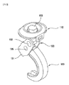
添付の図1は本発明の第1実施例に係る足場用仮設足場板固定装置の分解斜視図であり、図2は図1の組立斜視図であり、図3は図2の断面図及び設置状態図である。 1 is an exploded perspective view of a temporary scaffolding plate fixing device for scaffolding according to a first embodiment of the present invention, FIG. 2 is an assembly perspective view of FIG. 1, FIG. 3 is a sectional view and installation of FIG. It is a state diagram.
これらの図面によれば、本発明の第1実施例に係る足場用仮設足場板固定装置は、足場1に安着される仮設足場板4を固定させるためのものであって、特に、鋼管足場1と仮設足場板4を結束するためのものである。 According to these drawings, the temporary scaffolding board fixing device for scaffolding according to the first embodiment of the present invention is for fixing the temporary scaffolding board 4 seated on the scaffolding 1, and in particular, the steel pipe scaffolding. 1 for binding the temporary scaffolding board 4 and the temporary scaffolding board 4.
具体的に説明すれば、第1実施例の足場用仮設足場板固定装置は、前記仮設足場板4の上側の端に一部が安着されたまま前記仮設足場板4をクランプする足場板クランプ110と、前記鋼管足場1の外周を部分的に囲むようにクランプする円弧状の鋼管足場クランプ120と、前記足場板クランプ110と鋼管足場クランプ120とを連結する連結部材130とで構成される。
Specifically, the temporary scaffolding plate fixing device for scaffolding of the first embodiment is a scaffolding plate clamp for clamping the temporary scaffolding plate 4 while a part of the temporary scaffolding plate 4 is seated on the upper end of the temporary scaffolding plate 4. 110, an arc-shaped steel
ここで、前記連結部材130は、前記足場板クランプ110と鋼管足場クランプ120との間に配置され、上部ピン孔131a及び下部ピン孔131bが形成された連結ブラケット131と、前記上部ピン孔131aに嵌合され、貫通孔132aが形成された結束ピン132と、前記足場板クランプ110を上部から貫通して前記結束ピン132の貫通孔132aを貫通したまま下部にナットNが締結仕上げられる締結ボルト133と、前記足場板クランプ110と結束ピン132との間に介在される弾性部材134と、前記下部ピン孔131b及び前記鋼管足場クランプ120の上端を貫通して連結ブラケット131と鋼管足場クランプ120とを結合する結合ピン135とで構成されることができる。
Here, the connecting
一方、前記弾性部材134は、前記足場板クランプ110と結束ピン132との間で締結ボルト133が貫通するように設置される下部開口型のスプリングハウジング134aと、前記スプリングハウジング134aに挿入されるスプリング134bと、前記スプリングハウジング134aの下部で前記スプリング134bを弾力支持するように設置されるスプリング支持台134cとで構成されることができる。
Meanwhile, the
未説明の符号111は、前記足場板クランプ110の両端に形成されて、隣接する仮設足場板4の端部に密接して足場板クランプ110の遊動を防止する一方、隣接する仮設足場板4の間の間隔を一定に保持させるスペーサである。
The
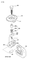
添付の図4は、本発明の第2実施例に係る足場用仮設足場板固定装置の分解斜視図であり、図5は図4の組立斜視図であり、図6は図5の断面図及び設置状態図である。 FIG. 4 attached herewith is an exploded perspective view of a temporary scaffolding plate fixing device for scaffolding according to a second embodiment of the present invention, FIG. 5 is an assembly perspective view of FIG. 4, and FIG. 6 is a sectional view of FIG. It is an installation state figure.
これらの図面によれば、本発明の第2実施例に係る足場用仮設足場板固定装置は、足場2に安着される仮設足場板4を固定させるためのものであって、特に水平端部を有する足場と仮設足場板を結束するためのものである。
According to these drawings, the temporary scaffolding board fixing device for scaffolding according to the second embodiment of the present invention is for fixing the temporary scaffolding board 4 which is seated on the
具体的に説明すれば、第2実施例の足場用仮設足場板固定装置は、前記仮設足場板4の上側の端に一部が安着されたまま前記仮設足場板4をクランプする足場クランプ210と、前記足場2の水平端部2aをクランプするC型の足場クランプ220と、前記足場板クランプ210と足場クランプ220とを連結する連結部材230とで構成されることができる。
Specifically, the temporary scaffolding board fixing device for scaffolding of the second embodiment is a
ここで、前記連結部材230は、前記足場板クランプ210と足場クランプ220との間に配置され、上部ピン孔231a及び下部ピン孔231bが形成された連結ブラケット231と、前記上部ピン孔231aに嵌合され、貫通孔232aが形成された結束ピン232と、前記足場クランプ210を上部から貫通して前記結束ピン232の貫通孔232aを貫通したまま下部にナットNが締結仕上げられる締結ボルト233と、前記足場板クランプ210と結束ピン232との間に介在される弾性部材234と、前記下部ピン孔231b及び前記足場クランプ220の上端を貫通して連結ブラケット231と足場クランプ220とを結合する結合ピン235とで構成されることができる。
Here, the
一方、前記弾性部材234は、前記足場板クランプ210と結束ピン232との間で締結ボルト233が貫通するように設置される下部開口型のスプリングハウジング234aと、前記スプリングハウジング234aに挿入されるスプリング234bと、前記スプリングハウジング234aの下部で前記スプリング234bを弾力支持するように設置されるスプリング支持台234cとで構成されることができる。
Meanwhile, the
未説明の符号211は、前記足場板クランプ210の両端に形成され、隣接する仮設足場板4の端部に密接して足場板クランプ210の遊動を防止する一方、隣接する仮設足場板4の間の間隔を一定に保持させるスペーサである。
The
図7は、本発明の第3実施例に係る足場用仮設足場板固定装置の分解斜視図であり、図8は図7の組立斜視図であり、図9は図8の断面図及び設置状態図である。 7 is an exploded perspective view of a temporary scaffolding plate fixing device for scaffolds according to a third embodiment of the present invention, FIG. 8 is an assembled perspective view of FIG. 7, FIG. 9 is a sectional view of FIG. It is a figure.
これらの図面によれば、本発明の第3実施例に係る足場用仮設足場板固定装置は、足場3に安着される仮設足場板4を固定させるためのものであって、特に垂直端部を有する足場と仮設足場板を結束するためのものである。 According to these drawings, a temporary scaffolding board fixing device for scaffolding according to a third embodiment of the present invention is for fixing a temporary scaffolding board 4 which is seated on a scaffolding 3, and in particular a vertical end portion. It is for binding the scaffolding having and the temporary scaffolding board.
具体的に説明すれば、前記仮設足場板4の上側の端に一部が安着されたまま前記仮設足場板4をクランプする足場板クランプ310と、前記足場3の垂直端部3aをクランプする足場クランプ320と、前記足場板クランプ310と足場クランプ320とを連結する連結部材330とで構成されることができる。
More specifically, a
ここで、前記連結部材330は、前記足場板クランプ310と足場クランプ320との間に配置され、上部ピン孔331a及び下部ピン孔331bが形成された連結ブラケット331と、前記上部ピン孔331aに嵌合され、貫通孔332aが形成された結束ピン332と、前記足場板クランプ310を上部から貫通して前記結束ピン332の貫通孔332aを貫通したまま下部にナットNとして締結仕上げられる締結ボルト333と、前記足場板クランプ310と結束ピン332との間に介在される弾性部材334と、前記下部ピン孔331b及び前記足場クランプ320の上端を貫通して連結ブラケット331と足場クランプ320とを結合する結合ピン335とで構成されることができる。
Here, the
また、前記足場クランプ320は、前記結合ピン334により前記連結ブラケット331の下部に結合され、下端に前記足場3の垂直端部3aが凹入される凹入溝321aが形成されたクランプハウジング321と、前記クランプハウジング321の内部の両側に配置され、前記結合ピン335により前記クランプハウジング321に上部が結合されて結合ピン332を中心として相互反対方向にリンク回転する一対のリンク節323と、前記各リンク節323の下端にピン結合されたまま、前記リンク節323のリンク回転によって前記クランプハウジング321の凹入溝321aへ凹入される足場3の垂直端部3aを両方で把持する二対のクランパー324とで構成されることができる。
In addition, the
一方、前記弾性部材334は、前記足場板クランプ310と結束ピン332との間で締結ボルト333が貫通するように設置される下部開口型のスプリングハウジング334aと、前記スプリングハウジング334aに挿入されるスプリング334bと、前記スプリングハウジング334aの下部で前記スプリング334bを弾力支持するように設置されるスプリング支持台334cとで構成されることができる。
Meanwhile, the
未説明の符号311は、前記足場板クランプ310の両端に形成され、隣接する仮設足場板4の端部に密接して足場板クランプ310の遊動を防止する一方、隣接する仮設足場板4の間の間隔を一定に保持させるスペーサである。
The
Claims (1)
前記足場板クランプ(110)と前記鋼管足場クランプ(120)との間に配置される連結部材(130)は、上部ピン孔(131a)及び下部ピン孔(131b)が形成された連結ブラケット(131)と、前記上部ピン孔(131a)に嵌合され、貫通孔(132a)が形成された結束ピン(132)と、前記足場板クランプ(110)を上部から貫通して前記結束ピン(132)の貫通孔(132a)を貫通したまま下部にナット(N)が締結される締結ボルト(133)と、前記足場板クランプ(110)と前記結束ピン(132)との間に介在される弾性部材(134)と、前記下部ピン孔(131b)を貫通して前記連結ブラケット(131)と前記鋼管足場クランプ(120)とを結束させる結合ピン(135)とを含み、
前記鋼管足場(1)は前記連結ブラケット(131)と前記鋼管足場クランプ(120)によって挟持され、
前記締結ボルト(133)が前記ナット(N)に対して締結されることにより、前記連結ブラケット(131)は前記締結ボルト(133)の長軸方向に引き上げられ、前記連結ブラケット(131)と前記鋼管足場(1)との接触点を支点として、前記鋼管足場クランプ(120)は前記連結ブラケット(131)との間が狭まるよう作動し、前記鋼管足場クランプ(120)が前記連結ブラケット(131)に対して前記鋼管足場(1)を締め付けて固定する構成を特徴とする足場用仮設足場板固定装置。 A scaffolding plate clamp (110) partially seated on the upper end of the temporary scaffolding plate (4) for fixing the temporary scaffolding plate (4) seated on the steel pipe scaffolding (1), and the steel pipe scaffolding an arcuate one steel tube scaffold clamp for clamping to the outer periphery partially surround (1) (120), connecting members for connecting the scaffolding plate clamp (110) and the steel pipe scaffold clamp (120) (130) In the temporary scaffolding plate fixing device for steel pipe scaffold composed of
The connecting member (130) disposed between the scaffold plate clamp (110) and the steel pipe scaffold clamp (120), connecting bracket (131 upper pin holes (131a) and the lower pin holes (131b) are formed ), a binding pin (132) fitted into the upper pin hole (131a) and having a through hole (132a), and the binding pin (132) penetrating the scaffolding plate clamp (110) from above. an elastic member which is interposed between the fastening bolts (133) to the nut in the lower part while penetrating (N) is fastened, and the scaffolding plate clamp (110) and said tying pin (132) through holes a (132a) of and (134), seen including a coupling pin (135) for bundling and said lower pin holes (131b) the steel pipe scaffold clamp and the connecting bracket (131) through the (120),
The steel pipe scaffold (1) is clamped by the connecting bracket (131) and the steel pipe scaffolding clamp (120),
When the fastening bolt (133) is fastened to the nut (N), the connecting bracket (131) is pulled up in the major axis direction of the fastening bolt (133), and the connecting bracket (131) and the connecting bracket (131) are pulled up. The steel pipe scaffolding clamp (120) operates so as to be narrowed between the steel pipe scaffolding clamp (120) and the connecting bracket (131) with the contact point with the steel pipe scaffolding (1) as a fulcrum, and the steel pipe scaffolding clamp (120) causes the connecting bracket (131). A temporary scaffolding plate fixing device for scaffolding, characterized in that the steel pipe scaffolding (1) is fastened and fixed to the above .
Applications Claiming Priority (3)
| Application Number | Priority Date | Filing Date | Title |
|---|---|---|---|
| KR10-2016-0106894 | 2016-08-23 | ||
| KR1020160106894A KR101763077B1 (en) | 2016-08-23 | 2016-08-23 | APPARATUS of FIXING FOOTING SCAFFOLDING |
| PCT/KR2017/009181 WO2018038518A1 (en) | 2016-08-23 | 2017-08-23 | Apparatus for fixing scaffold plank for scaffold |
Publications (2)
| Publication Number | Publication Date |
|---|---|
| JP2019508606A JP2019508606A (en) | 2019-03-28 |
| JP6723364B2 true JP6723364B2 (en) | 2020-07-15 |
Family
ID=59422123
Family Applications (1)
| Application Number | Title | Priority Date | Filing Date |
|---|---|---|---|
| JP2018535890A Expired - Fee Related JP6723364B2 (en) | 2016-08-23 | 2017-08-23 | Temporary scaffolding board fixing device for scaffolding |
Country Status (4)
| Country | Link |
|---|---|
| JP (1) | JP6723364B2 (en) |
| KR (1) | KR101763077B1 (en) |
| CN (1) | CN108603376A (en) |
| WO (1) | WO2018038518A1 (en) |
Families Citing this family (2)
| Publication number | Priority date | Publication date | Assignee | Title |
|---|---|---|---|---|
| JP3209357U (en) * | 2016-12-28 | 2017-03-09 | 株式会社Osk | Scaffolding plate fixture |
| KR102408944B1 (en) * | 2021-12-29 | 2022-06-14 | 서대운 | Attachment for steel pipe clamping |
Family Cites Families (9)
| Publication number | Priority date | Publication date | Assignee | Title |
|---|---|---|---|---|
| JPS5116728A (en) * | 1974-08-01 | 1976-02-10 | Juichi Ishikawa | PAIPUASHIBAYOPANERUKURANPU |
| JPH049888U (en) * | 1990-05-16 | 1992-01-28 | ||
| JPH0416782U (en) * | 1990-06-01 | 1992-02-12 | ||
| JPH0532378U (en) * | 1991-10-07 | 1993-04-27 | 大成鑿岩機株式会社 | Anchor hanging method |
| KR200254637Y1 (en) * | 2001-08-07 | 2001-12-01 | 김진곤 | Clamp for bridge |
| JP2007001671A (en) * | 2005-06-21 | 2007-01-11 | Nippon Clamp Kk | Clamp for hanging vertically |
| KR200450331Y1 (en) * | 2008-04-30 | 2010-09-24 | 배용웅 | Fixing structure for concrete form |
| KR101588868B1 (en) * | 2014-11-24 | 2016-02-12 | 김현식 | Fixing apparatus of scaffold and structure body |
| KR101588984B1 (en) * | 2014-12-29 | 2016-01-28 | 김현식 | Fixing apparatus of scaffold and structure body |
-
2016
- 2016-08-23 KR KR1020160106894A patent/KR101763077B1/en active IP Right Grant
-
2017
- 2017-08-23 WO PCT/KR2017/009181 patent/WO2018038518A1/en active Application Filing
- 2017-08-23 JP JP2018535890A patent/JP6723364B2/en not_active Expired - Fee Related
- 2017-08-23 CN CN201780009688.1A patent/CN108603376A/en not_active Withdrawn
Also Published As
| Publication number | Publication date |
|---|---|
| CN108603376A (en) | 2018-09-28 |
| JP2019508606A (en) | 2019-03-28 |
| WO2018038518A1 (en) | 2018-03-01 |
| KR101763077B1 (en) | 2017-07-28 |
Similar Documents
| Publication | Publication Date | Title |
|---|---|---|
| US10240692B2 (en) | Fastening-type pipe supporting apparatus for curved pipe | |
| KR101711614B1 (en) | Connection structure of steel column and steel beam | |
| JP6723364B2 (en) | Temporary scaffolding board fixing device for scaffolding | |
| US8646241B2 (en) | Intercoupled piping assembly | |
| TW201537000A (en) | Constraint bracing device having inspection window | |
| JP6067403B2 (en) | Beam-to-column connection and steel beam connection at beam-to-column connection | |
| JP5567994B2 (en) | Connector | |
| KR101236184B1 (en) | Pendant assembling type prefabricated scaffolding system device for large heat power plant | |
| KR101773434B1 (en) | Coupling device for concrete and steel File | |
| CN109689993A (en) | Detachable fastening system for two crossed module plate-girders | |
| KR100960943B1 (en) | A steel pipe scaffold for construction work | |
| JP2012072562A (en) | Junction structure of hollow square bar, and bathroom unit installation base | |
| KR20200084290A (en) | Improved pipe coupling | |
| KR101454643B1 (en) | scaffold pipe with connector | |
| KR101453626B1 (en) | Connection structure of steel member with a closed section | |
| KR102552341B1 (en) | Apparatus for the vertical connection of precast concrete wall using the C-shaped damper for energy dissipation and its construction method | |
| KR101580236B1 (en) | Beam Connecting Tool | |
| JP2017066665A (en) | Reinforcement device of through hole in steel beam | |
| JP4043976B2 (en) | Reinforcing device | |
| KR101992423B1 (en) | Flange structure for water pipes with improved connection | |
| JP7264467B2 (en) | Vertical strut for temporary scaffolding and temporary scaffolding system using the same | |
| KR20180073032A (en) | Pipe connector and pipe additional strengthening for vinyl house using the same | |
| JP2019100118A (en) | Post-attachment brace joint structure | |
| KR101639276B1 (en) | Korean house memebers connection structure | |
| KR101454975B1 (en) | Clamp Embeded Pipe |
Legal Events
| Date | Code | Title | Description |
|---|---|---|---|
| A621 | Written request for application examination |
Free format text: JAPANESE INTERMEDIATE CODE: A621 Effective date: 20180725 |
|
| A977 | Report on retrieval |
Free format text: JAPANESE INTERMEDIATE CODE: A971007 Effective date: 20190710 |
|
| A131 | Notification of reasons for refusal |
Free format text: JAPANESE INTERMEDIATE CODE: A131 Effective date: 20190730 |
|
| A601 | Written request for extension of time |
Free format text: JAPANESE INTERMEDIATE CODE: A601 Effective date: 20191030 |
|
| A521 | Request for written amendment filed |
Free format text: JAPANESE INTERMEDIATE CODE: A523 Effective date: 20191227 |
|
| TRDD | Decision of grant or rejection written | ||
| A01 | Written decision to grant a patent or to grant a registration (utility model) |
Free format text: JAPANESE INTERMEDIATE CODE: A01 Effective date: 20200602 |
|
| A61 | First payment of annual fees (during grant procedure) |
Free format text: JAPANESE INTERMEDIATE CODE: A61 Effective date: 20200623 |
|
| R150 | Certificate of patent or registration of utility model |
Ref document number: 6723364 Country of ref document: JP Free format text: JAPANESE INTERMEDIATE CODE: R150 |
|
| LAPS | Cancellation because of no payment of annual fees |