JP7588570B2 - Power conversion device and abnormality determination method - Google Patents
Power conversion device and abnormality determination method Download PDFInfo
- Publication number
- JP7588570B2 JP7588570B2 JP2021155865A JP2021155865A JP7588570B2 JP 7588570 B2 JP7588570 B2 JP 7588570B2 JP 2021155865 A JP2021155865 A JP 2021155865A JP 2021155865 A JP2021155865 A JP 2021155865A JP 7588570 B2 JP7588570 B2 JP 7588570B2
- Authority
- JP
- Japan
- Prior art keywords
- neutral point
- voltage
- power conversion
- smoothing capacitor
- inverter
- Prior art date
- Legal status (The legal status is an assumption and is not a legal conclusion. Google has not performed a legal analysis and makes no representation as to the accuracy of the status listed.)
- Active
Links
Images


Landscapes
- Rectifiers (AREA)
- Inverter Devices (AREA)
Description
本発明は、電力変換装置、および異常判定方法に関する。 The present invention relates to a power conversion device and an abnormality determination method.
交流電圧を直流電圧に変換する、または直流電圧を交流電圧に変換する電力変換装置には、直流電圧の変動を抑制するための平滑コンデンサを備えている。平滑コンデンサは電力変換装置において重要な役割を果たす部品の一つであり、異常が発生した場合は電力変換装置の動作に大きく影響を及ぼす。 Power conversion devices that convert AC voltage to DC voltage or DC voltage to AC voltage are equipped with smoothing capacitors to suppress fluctuations in the DC voltage. Smoothing capacitors are one of the components that play an important role in power conversion devices, and if an abnormality occurs, it will have a significant impact on the operation of the power conversion device.
特許文献1には、平滑コンデンサの直流電圧からリップル電圧値を算出すると共に、リップル電圧値と、負荷電流の値に対応する比較リップル電圧値とを比較して平滑コンデンサの劣化を判定する技術が開示されている。
従来の技術では、平滑コンデンサの異常を精度よく検出することができなかった。 Conventional technology was not able to accurately detect abnormalities in smoothing capacitors.
本発明による電力変換装置は、交流電圧を正電位と、負電位と、前記正電位と前記負電位の中間の中性点電位との3つの電位を有する直流電圧に変換する、または前記3つの電位を有する直流電圧を交流電圧に変換する電力変換回路と、前記正電位と前記中性点電位との間、および前記中性点電位と前記負電位との間にそれぞれ接続された平滑コンデンサと、前記平滑コンデンサが接続された各電位間の電圧を検出する直流電圧検出器と、前記電力変換回路を制御する制御部と、を備え、前記制御部は、前記直流電圧検出器の検出値と前記中性点電位を中性点電圧指令に追従させる操作量とに基づいて前記中性点電位を制御し、前記操作量の変動成分により前記平滑コンデンサの異常を判定する。
本発明による異常判定方法は、交流電圧を正電位と、負電位と、前記正電位と前記負電位の中間の中性点電位との3つの電位を有する直流電圧に変換する、または前記3つの電位を有する直流電圧を交流電圧に変換する電力変換回路と、前記正電位と前記中性点電位との間、および前記中性点電位と前記負電位との間にそれぞれ接続された平滑コンデンサと、前記平滑コンデンサが接続された各電位間の電圧を検出する直流電圧検出器と、前記電力変換回路を制御する制御部と、を備える電力変換装置における平滑コンデンサの異常判定方法であって、前記直流電圧検出器の検出値と前記中性点電位を中性点電圧指令に追従させる操作量とに基づいて前記中性点電位を制御し、前記操作量の変動成分により前記平滑コンデンサの異常を判定する。
The power conversion device according to the present invention comprises a power conversion circuit that converts an AC voltage into a DC voltage having three potentials, namely a positive potential, a negative potential, and a neutral point potential halfway between the positive potential and the negative potential, or that converts a DC voltage having the three potentials into an AC voltage, smoothing capacitors connected between the positive potential and the neutral point potential and between the neutral point potential and the negative potential, respectively, a DC voltage detector that detects the voltage between each potential to which the smoothing capacitor is connected, and a control unit that controls the power conversion circuit, wherein the control unit controls the neutral point potential based on the detection value of the DC voltage detector and an operating variable that causes the neutral point potential to follow a neutral point voltage command, and determines an abnormality in the smoothing capacitor based on the fluctuation component of the operating variable.
The method for determining an abnormality according to the present invention is a method for determining an abnormality in a smoothing capacitor in a power conversion device that includes a power conversion circuit that converts an AC voltage into a DC voltage having three potentials: a positive potential, a negative potential, and a neutral point potential halfway between the positive potential and the negative potential, or that converts a DC voltage having the three potentials into an AC voltage, smoothing capacitors connected between the positive potential and the neutral point potential and between the neutral point potential and the negative potential, respectively, a DC voltage detector that detects the voltage between each potential to which the smoothing capacitor is connected, and a control unit that controls the power conversion circuit, wherein the neutral point potential is controlled based on the detection value of the DC voltage detector and an operating variable that causes the neutral point potential to follow a neutral point voltage command, and an abnormality in the smoothing capacitor is determined based on the fluctuation component of the operating variable.
本発明によれば、電力変換装置における平滑コンデンサの異常を精度よく検出することが可能となる。 The present invention makes it possible to accurately detect abnormalities in smoothing capacitors in power conversion devices.
[第1実施形態]
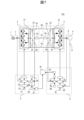
図1は、第1実施形態に係る電力変換装置100の全体構成図である。
電力変換装置100は、交流電源1からの交流電力を直流電力に変換するコンバータユニット(コンバータともいう)2と、コンバータユニット2が出力する直流電力を所望の交流電力に変換するインバータユニット(インバータともいう)3と、コンバータユニット2を制御するコンバータ制御装置5と、インバータユニット3を制御するインバータ制御装置6と、を備える。電動機4は、インバータユニット3が出力する交流電力により駆動される。
[First embodiment]
FIG. 1 is an overall configuration diagram of a
The
コンバータユニット2は、いわゆる3レベルコンバータであり、交流電力を、正電位(第1電位)レベルと、中性点(零)電位(第2電位)レベルと、負電位(第3電位)レベルとの直流電力に変換する。インバータユニット3は、いわゆる3レベルインバータであり、コンバータユニット2で変換された、正電位(第1電位)レベルと、中性点(零)電位(第2電位)レベルと、負電位(第3電位)レベルとの直流電力を、交流電力に変換する。コンバータユニット2と、インバータユニット3との正電位レベルは、P配線40で接続され、中性点電位レベルは、C配線41で接続され、負電位レベルは、N配線42で接続されている。
The
コンバータユニット2は、コンバータ電力変換回路21と、直流電圧の変動を抑制するためのコンバータP側平滑コンデンサ22(コンバータ側平滑コンデンサ22、平滑コンデンサ22と表記する場合がある)と、コンバータN側平滑コンデンサ23(コンバータ側平滑コンデンサ23、平滑コンデンサ23と表記する場合がある)と、コンバータP側平滑コンデンサ22の端子間電圧を測定するためのコンバータP側直流電圧検出器25(直流電圧検出器25と表記する場合がある)と、コンバータN側平滑コンデンサ23の端子間電圧を測定するためのコンバータN側直流電圧検出器26(直流電圧検出器26と表記する場合がある)と、C配線41に接続され、直流共振を抑制するためのコンバータ中性点抵抗24と、を備える。
The
コンバータユニット2は、図1においては、コンバータ電力変換回路21の1相分の構成のみ(コンバータ中性点抵抗24、直流電圧検出器25、直流電圧検出器26を除く)を示しているが、他の2相も同様の構成を備えている。1相分のコンバータ電力変換回路21は、4個のスイッチング素子が直列に接続され、各スイッチング素子と並列にダイオード素子が接続される直列回路を構成している。直列回路の中間点には交流電源1からの1相が接続される。中間点と負電位レベルとの間の2個のスイッチング素子の第1接続点と、中間点と正電位レベルとの間の2個のスイッチング素子の第2接続点と、の間には2個のダイオードが、第1接続点から第2接続点へ向けて順方向に直列に接続されている。そして、この2個のダイオードの中間に、コンバータP側平滑コンデンサ22とコンバータN側平滑コンデンサ23の中性点電位レベルが、さらにコンバータ中性点抵抗24が接続される。
In FIG. 1, the
電力変換装置100は、コンバータユニット2の出力電流を検出して出力する電流検出器7を備え、電流検出器7、及び直流電圧検出器25、26により検出された検出値の信号(出力信号)は、コンバータ制御装置5に入力される。コンバータ制御装置5は、入力された検出値に基づいて、各種演算処理を行い、コンバータ電力変換回路21のスイッチング素子をオン・オフ制御するためのパルス信号を出力する。すなわち、コンバータ制御装置5は、変換される直流電力が所望の値となるようにコンバータ電力変換回路21を制御する。
The
インバータユニット3は、インバータ電力変換回路31と、インバータP側平滑コンデンサ32(インバータ側平滑コンデンサ32、平滑コンデンサ32と表記する場合がある)と、インバータN側平滑コンデンサ33(インバータ側平滑コンデンサ33、平滑コンデンサ33と表記する場合がある)と、インバータP側平滑コンデンサ32の端子間電圧を測定するためのインバータP側直流電圧検出器35(直流電圧検出器35と表記する場合がある)と、インバータN側平滑コンデンサ33の端子間電圧を測定するためのインバータN側直流電圧検出器36(直流電圧検出器36と表記する場合がある)と、C配線41に接続され、直流共振を抑制するためのインバータ中性点抵抗34と、を備える。
The
インバータユニット3は、図1においては、インバータ電力変換回路31の1相分の構成のみ(インバータ中性点抵抗34、直流電圧検出器35、直流電圧検出器36を除く)を示しているが、他の2相も同様の構成を備えている。1相分のインバータ電力変換回路31は、4個のスイッチング素子が直列に接続され、各スイッチング素子と並列にダイオード素子が接続される直列回路を構成している。直列回路の中間点には電動機4の1相に接続される。中間点と負電位レベルとの間の2個のスイッチング素子の第1接続点と、中間点と正電位レベルとの間の2個のスイッチング素子の第2接続点と、の間には2個のダイオードが、第1接続点から第2接続点へ向けて順方向に直列に接続されている。そして、この2個のダイオードの中間に、インバータP側平滑コンデンサ32とインバータN側平滑コンデンサ33の中性点電位レベルが、さらにインバータ中性点抵抗34が接続される。
In FIG. 1, the
電力変換装置100は、電動機4の速度を検出して出力する速度検出器8と、インバータユニット3の出力電流を検出して出力する電流検出器9とを備え、速度検出器8、電流検出器9、及び直流電圧検出器35、36により検出された検出値の信号(出力信号)は、インバータ制御装置6に入力される。インバータ制御装置6は、入力された検出値に基づいて、各種演算処理を行い、インバータ電力変換回路31のスイッチング素子をオン・オフ制御するためのパルス信号を出力する。すなわち、インバータ制御装置6は、電動機4の出力トルクや速度が所望の特性を満たすようにインバータ電力変換回路31を制御する。
The
コンバータ制御装置5は、直流電圧指令発生器51と、直流電圧制御器52と、電流制御器53と、パルス生成器54と、コンバータ側中性点電圧制御器55とを備える。
The
直流電圧指令発生器51は、コンバータユニット2から出力させる直流電圧の電圧値を示す直流電圧指令値を直流電圧制御器52に出力する。
The DC
直流電圧制御器52は、直流電圧指令発生器51から入力される直流電圧指令値と、直流電圧検出器25、26から入力される直流電圧の検出値とに基づいて、コンバータ出力電流指令値を演算して、電流制御器53に出力する。具体的には、直流電圧制御器52は、直流電圧検出器25、26のそれぞれから入力される直流電圧の検出値の合計値が直流電圧指令値と一致するようにコンバータ出力電流指令値を演算する。
The
コンバータ側中性点電圧制御器55は、直流電圧検出器25、26のそれぞれから入力される直流電圧の検出値の差に基づいて、中性点電圧が零となるような電圧指令を演算して電流制御器53に出力する。
The converter-side neutral
電流制御器53は、電流検出器7から出力されるコンバータ出力電流検出値が、直流電圧制御器52から入力されるコンバータ出力電流指令値と一致するようにコンバータ電圧指令値を演算してパルス生成器54に出力する。この際、電流制御器53は、コンバータ側中性点電圧制御器55から入力される電圧指令も考慮して、中性点電圧を零にコントロールするようにコンバータ電圧指令値を演算する。
The
パルス生成器54は、電流制御器53から入力されるコンバータ電圧指令値に基づいて、コンバータ電力変換回路21の各スイッチング素子をオン・オフ制御するためのパルス信号を演算して、パルス信号をコンバータ電力変換回路21に出力する。
The
インバータ制御装置6は、速度指令発生器61と、速度制御器62と、電流制御器63と、パルス生成器64と、インバータ側中性点電圧制御器65と、インバータ側変動成分演算器66と、インバータ側平滑コンデンサ異常判定器67と、インバータ側中性点電圧指令発生器68を備える。
The
速度指令発生器61は、電動機4を動作させる速度を示す速度指令値を速度制御器62に出力する。
The
速度制御器62は、速度検出器8から入力される速度検出値が、速度指令発生器61から入力される速度指令値と一致するようにインバータ出力電流指令値を演算し、インバータ出力電流指令値を電流制御器63に出力する。
The
電流制御器63は、電流検出器9から入力されるインバータ出力電流検出値が、速度制御器62から入力されるインバータ出力電流指令値と一致するようにインバータ電圧指令値を演算してパルス生成器64に出力する。この際、電流制御器63は、インバータ側中性点電圧制御器65から入力される電圧指令を考慮して、インバータ電圧指令値を演算する。なお、平滑コンデンサの異常判定を行う場合は、インバータ側中性点電圧制御器65から後述の操作量が電流制御器63へ入力される。この操作量は、電圧指令に相当するもので、電流制御器63は、インバータ側中性点電圧制御器65から入力される操作量を考慮して、インバータ電圧指令値を演算する。
The
パルス生成器64は、電流制御器63から入力されるインバータ出力電圧指令値に基づいて、インバータ電力変換回路31の各スイッチング素子をオン・オフ制御するためのパルス信号を演算して、パルス信号をインバータ電力変換回路31に出力する。
The
インバータ側中性点電圧指令発生器68は、電力変換装置100の通常動作時には、インバータ側中性点電圧制御器65に対して中性点電圧の目標値となる中性点電圧指令を与える。通常動作時における中性点電圧指令は所望の値(波形信号ではない静的な値)である。電力変換装置100の待機時等において平滑コンデンサの劣化等の異常を判定する場合には、インバータ側中性点電圧指令発生器68は、インバータ側中性点電圧制御器65に対して波形信号を成す中性点電圧指令を与える。波形信号の詳細は後述する。
During normal operation of the
インバータ側中性点電圧制御器65は、直流電圧検出器35、36の検出値から算出される中性点電圧と目標とする中性点電圧指令値との差に基づいて、中性点電圧を中性点電圧指令に追従させるための操作量を演算して、操作量をインバータ側変動成分演算器66および電流制御器63へ出力する。
The inverter side neutral
インバータ側変動成分演算器66は、インバータ側中性点電圧制御器65より入力された操作量に基づいて、平滑コンデンサの異常判断時に、中性点電圧指令を波形信号で変化させたときの操作量の変動成分を抽出し、インバータ側平滑コンデンサ異常判定器67に出力する。
The inverter side
インバータ側平滑コンデンサ異常判定器67は、インバータ側変動成分演算器66にて出力されるインバータ側中性点電圧制御器65の操作量において、平滑コンデンサの異常発生時に生じる変動成分の変化に基づいて、インバータP側平滑コンデンサ32およびインバータN側平滑コンデンサ33の異常を判定する。インバータ側平滑コンデンサ異常判定器67は、異常がある平滑コンデンサを検出した場合には、異常に関する情報や点検・交換等を推奨するメッセージなどを表示器70に表示する。なお、表示器70は電力変換装置100内にあってもよく、電力変換装置100外にあってもよい。
The inverter-side smoothing capacitor abnormality determiner 67 determines abnormalities in the inverter P-
次に、平滑コンデンサの異常判定について詳細に説明する。
インバータユニット3の中性点電圧は、インバータ側中性点電圧制御器65により、通常零に制御されており、その制御器の制御定数(例えば、比例積分制御器の場合は比例ゲインと積分時定数)は、制御対象となる中性点電圧の挙動に関係する平滑コンデンサの容量に基づいて計算される。インバータ中性点抵抗34は高い抵抗値の抵抗を用いて、インバータ中性点抵抗34により他の平滑コンデンサ22、23から分離されているため、インバータユニット3の中性点電圧の挙動に関係する平滑コンデンサは、インバータP側平滑コンデンサ32とインバータN側平滑コンデンサ33となる。
Next, the determination of an abnormality in the smoothing capacitor will be described in detail.
The neutral point voltage of the
平滑コンデンサの異常判定では、インバータ側中性点電圧指令発生器68は、波形信号を成す中性点電圧指令を目標値として中性点電圧制御器65へ入力する。中性点電圧制御器65は、その目標値に制御対象である中性点電圧が追従するように、直流電圧検出器35、36の検出値から算出される中性点電圧と目標値である中性点電圧指令値との差に基づいて、中性点電圧を中性点電圧指令に追従させるための操作量を演算する。この時の操作量は、設計時の制御応答と設計時に用いた平滑コンデンサ容量と中性点電圧指令の特性から、予め計算して求めておく。
When determining whether the smoothing capacitor is abnormal, the inverter-side neutral point
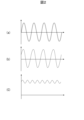
図2(a)、図2(b)、図2(c)は、平滑コンデンサが正常な場合において、操作量と変動成分との関係の一例を示すグラフである。図2(a)は、点線で中性点電圧指令を、実線で中性点電圧を示す。同図において、横軸は時間、縦軸は電圧である。図2(b)は、操作量を示す。同図において、横軸は時間、縦軸は大きさである。図2(c)は、変動成分を示す。同図において、横軸は時間、縦軸は大きさである。
図2(a)の点線に示すように、平滑コンデンサの異常判定時に、インバータ側中性点電圧指令発生器68から目標値となる波形信号、例えば、正弦波の信号を与える。
Figures 2(a), 2(b), and 2(c) are graphs showing an example of the relationship between the manipulated variable and the fluctuation component when the smoothing capacitor is normal. In Figure 2(a), the dotted line indicates the neutral point voltage command, and the solid line indicates the neutral point voltage. In this figure, the horizontal axis indicates time, and the vertical axis indicates voltage. Figure 2(b) shows the manipulated variable. In this figure, the horizontal axis indicates time, and the vertical axis indicates magnitude. Figure 2(c) shows the fluctuation component. In this figure, the horizontal axis indicates time, and the vertical axis indicates magnitude.
As shown by the dotted line in FIG. 2A, when an abnormality is detected in the smoothing capacitor, a waveform signal, for example a sine wave signal, which is a target value is provided from the inverter side neutral point
インバータ側中性点電圧制御器65は、前述のようにして図2(b)にしめす操作量を演算する。操作量は正弦波の信号である中性点電圧指令と同様の正弦波となる。この操作量は、インバータ側変動成分演算器66および電流制御器63へ入力される。電流制御器63は、操作量を考慮して、インバータ電圧指令値を演算してパルス生成器64へ出力する。パルス生成器64は、インバータ出力電圧指令値に一致するように、パルス信号をインバータ電力変換回路31に出力する。その結果、中性点電圧は、図2(a)の実線で示すように、中性点電圧指令値と若干の時間遅れで、中性点電圧指令値と同様な正弦波となる。
The inverter side neutral
一方、インバータ側変動成分演算器66は、入力された操作量の変動成分を抽出する。図2(c)は、この操作量の変動成分を示す。操作量の変動成分は、例えば、操作量の絶対値を演算し一次遅れフィルタを通して抽出する。操作量の変動成分は、インバータ側平滑コンデンサ異常判定器67に出力する。
On the other hand, the inverter side
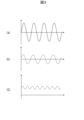
図3(a)、図3(b)、図3(c)は、平滑コンデンサが異常な場合において、操作量と変動成分との関係の一例を示すグラフである。図3(a)は、点線で中性点電圧指令を、実線で中性点電圧を示す。同図において、横軸は時間、縦軸は電圧である。図3(b)は、平滑コンデンサが劣化等によりその容量が低下していた場合を例に、その操作量を示す。同図において、横軸は時間、縦軸は大きさである。図3(c)は、変動成分を示す。同図において、横軸は時間、縦軸は大きさである。 Figures 3(a), 3(b), and 3(c) are graphs showing an example of the relationship between the manipulated variable and the fluctuation component when the smoothing capacitor is abnormal. In Figure 3(a), the dotted line shows the neutral point voltage command, and the solid line shows the neutral point voltage. In the figure, the horizontal axis is time and the vertical axis is voltage. Figure 3(b) shows the manipulated variable for an example where the capacity of the smoothing capacitor has decreased due to deterioration or the like. In the figure, the horizontal axis is time and the vertical axis is magnitude. Figure 3(c) shows the fluctuation component. In the figure, the horizontal axis is time and the vertical axis is magnitude.
インバータ側平滑コンデンサ異常判定器67は、入力された操作量の変動成分の変化に基づいて、インバータP側平滑コンデンサ32、インバータN側平滑コンデンサ33に異常があるか否かを判定する。例えば、操作量の変動成分の値と、基準値との差が、所定の閾値を超えている場合に、平滑コンデンサが異常であると判定する。
The inverter-side smoothing
ここで、基準値について述べる。前述したように、インバータ側中性点電圧制御器65の操作量は、設計時の制御応答と設計時に用いた平滑コンデンサの容量と中性点電圧指令の特性から、予め計算できる。そこで、予め計算によって基準値を算出しておき、算出された基準値を例えば、インバータ側平滑コンデンサ異常判定器67内の図示省略した記憶部に格納しておく。
Now, we will discuss the reference value. As mentioned above, the operation amount of the inverter side neutral
図2(a)と同様に、図3(a)の点線に示すように、平滑コンデンサの異常判定時に、インバータ側中性点電圧指令発生器68から目標値として、例えば、正弦波の信号を与える。
As shown by the dotted line in FIG. 3(a), similarly to FIG. 2(a), when an abnormality is detected in the smoothing capacitor, the inverter side neutral point
インバータ側中性点電圧制御器65は、前述と同様に、中性点電圧を中性点電圧指令に追従させるための操作量を演算する。図3(b)は、この操作量を示す。平滑コンデンサが劣化等によりその容量が低下していれば、図2(a)の点線で示す正弦波と同じ正弦波の中性点電圧指令に追従させるのに必要なインバータ側中性点電圧制御器65の操作量は、図2(b)と比較して、操作量の振幅が小さくなる。そして、インバータ側変動成分演算器66により抽出した変動成分は、図3(c)に示すように、図2(c)と比較して小さくなる。
The inverter side neutral
図4は、操作量の変動成分の値と平滑コンデンサの劣化度合いとの関係を示す図である。横軸は、劣化度合いを、縦軸は変動成分の大きさを示す。
図4に示すように、変動成分が小さくなるほど劣化度合いが大きくなる。劣化度合いは、1が基準であり、1~c1は正常範囲であることを示す。劣化度合いが、c1~c2は、劣化が若干進んでおり、平滑コンデンサの交換推奨レベルであることを示す。劣化度合いが、c2以上は、劣化が更に進んでおり、平滑コンデンサの要交換レベルを示している。図4に示すように、操作量の変動成分と平滑コンデンサの劣化度合いは直線的な関係にあるので、操作量の変動成分により平滑コンデンサの異常を精度よく検出することが可能となる。なお、操作量の変動成分を大きさで示したが、電圧値などその他の指標(物理量)で表してもよく、以降は、変動成分の値と称する。
4 is a diagram showing the relationship between the value of the fluctuation component of the manipulated variable and the degree of deterioration of the smoothing capacitor, where the horizontal axis represents the degree of deterioration and the vertical axis represents the magnitude of the fluctuation component.
As shown in FIG. 4, the smaller the fluctuation component, the greater the degree of deterioration. The deterioration degree is 1 as a reference, and 1 to c1 indicate a normal range. Degrees of deterioration of c1 to c2 indicate that the deterioration is slightly advanced and replacement of the smoothing capacitor is recommended. Degrees of deterioration of c2 or more indicate that the deterioration is further advanced and that the smoothing capacitor needs to be replaced. As shown in FIG. 4, the fluctuation component of the operation amount and the degree of deterioration of the smoothing capacitor are in a linear relationship, so that an abnormality in the smoothing capacitor can be detected with high accuracy by the fluctuation component of the operation amount. Note that although the fluctuation component of the operation amount is shown by a magnitude, it may be expressed by other indexes (physical quantities) such as a voltage value, and hereinafter, it will be referred to as the value of the fluctuation component.
平滑コンデンサに異常が無い、又は劣化の度合いが小さい場合には、図4に示すように、インバータ側中性点電圧制御器65による操作量の変動成分と基準値E0との差E1は小さい。一方、平滑コンデンサに異常(例えば、容量が大きく低下)がある場合には、基準値E0との差E2は大きくなる。
When there is no abnormality in the smoothing capacitor or the degree of deterioration is small, as shown in Figure 4, the difference E1 between the fluctuation component of the manipulated variable by the inverter side neutral
そこで、インバータ側平滑コンデンサ異常判定器67は、インバータ側中性点電圧制御器65の操作量の変動成分の値と基準値とを比較し、それらの差が所定の閾値以内であるか否かを判定し、インバータ側中性点電圧制御器65の操作量の変動成分と基準値との差が所定の閾値を超える場合には、平滑コンデンサが異常であると判定する。
The inverter-side smoothing
次に、インバータ側平滑コンデンサ異常判定器67で異常と判定した場合の表示器70の表示について説明する。
表示器70は、例えば、液晶ディスプレイ等の情報を表示可能な表示装置であり、各種情報を表示する。
Next, a description will be given of the display on the
The
インバータ側平滑コンデンサ異常判定器67は、異常がある平滑コンデンサを検出した場合には、異常に関する情報(例えば、異常のある平滑コンデンサを特定できる情報(例えば、デバイス番号))と、点検・交換等を推奨するメッセージとを表示器70に表示する。
When the inverter-side smoothing
ここで、インバータ側平滑コンデンサ異常判定器67は、平滑コンデンサの劣化等の異常を判定する閾値を複数備え、インバータ側中性点電圧制御器65の操作量の変動成分の値と各閾値とに基づいて、交換推奨レベルや、要交換レベルなど段階的に異なる異常判定を行っても良い。
The inverter-side smoothing
例えば、中性点電圧制御器の操作量の変動成分の値と基準値E0との差がレベルE1~レベルE2の場合は、平滑コンデンサの劣化が疑われるため点検・交換推奨であることを、さらにレベルE2を超える場合は、平滑コンデンサが異常である可能性が高いため、交換必須であることを表示器70に表示する。また、操作量の変動成分の値と基準値とを比較して、平滑コンデンサの劣化度合いを推定し、表示器70にその劣化度合いに関する情報を表示するようにしてもよい。
For example, when the difference between the value of the fluctuation component of the operation amount of the neutral point voltage controller and the reference value E0 is between level E1 and level E2, the
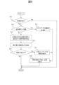
図5は、インバータ制御装置6による異常判定処理のフローチャートである。
異常判定を実施するために、電力変換装置100が待機状態であるかを判定する(ステップS11)。待機状態とは、電動機4が低速または無負荷の状態であり、例えば、速度検出器8により電動機4の速度を検出して、待機状態であるかを判定する。
FIG. 5 is a flowchart of the abnormality determination process performed by the
In order to perform the abnormality determination, it is determined whether the
待機状態である場合(ステップS11:Yes)、インバータ側平滑コンデンサ異常判定器67は、インバータユニット3に備えられたP側平滑コンデンサ32およびN側平滑コンデンサ33両端の電圧を直流電圧検出器35、36にて検出し、検出値と定格直流電圧とに乖離があるか否かを判定する(ステップS12)。定格直流電圧は、電力変換装置100の定格直流電圧である。
If the inverter is in a standby state (step S11: Yes), the inverter-side smoothing
直流電圧検出器35、36の検出値と定格直流電圧とで乖離がある場合(ステップS12:Yes)には、例えば、コンバータユニット2が正常に動作していない等の異常がある可能性が考えられるため、インバータ側平滑コンデンサ異常判定器67はコンバータユニット2に異常があると判定し、コンバータユニット2に異常があることを示す情報(例えば、「コンバータ異常」)を表示器70に表示し(ステップS13)、処理をステップS18に進める。
If there is a discrepancy between the detection values of the
一方、直流電圧検出器35、36の検出値と定格直流電圧とで乖離がない場合(ステップS12:No)には、インバータ側中性点電圧指令発生器68はインバータ側中性点電圧制御器65に正弦波の中性点電圧指令を与え、インバータ側中性点電圧制御器65は中性点電圧指令に中性点電圧を追従するための操作量を算出する(ステップS14)。
On the other hand, if there is no discrepancy between the detection values of the
次に、インバータ側変動成分演算器66は、インバータ側中性点電圧制御器65により算出された操作量の絶対値を計算し、一次遅れフィルタを通す等の処理を行うことによって、インバータ側中性点電圧制御器65による操作量の変動成分を抽出し、操作量の変動成分をインバータ側平滑コンデンサ異常判定器67に出力する(ステップS15)。
Next, the inverter side
次に、インバータ側平滑コンデンサ異常判定器67は、ステップS15で抽出されたインバータ側中性点電圧制御器65の操作量の変動成分の値と基準値とを比較し、平滑コンデンサに異常があるか否かを判定する(ステップS16)。
Next, the inverter-side smoothing
ステップS16において、抽出されたインバータ側中性点電圧制御器65の操作量の変動成分の値と基準値との間に、所定の閾値以上の乖離がある場合(ステップS16:Yes)、平滑コンデンサ32、33に異常があると判定し、平滑コンデンサ32、33に異常がある事を示す情報(例えば「平滑コンデンサ異常」)を表示器70に表示し(ステップS17)、処理をステップS18に進める。ステップS17において、図4を参照して説明したように、平滑コンデンサの劣化等の異常を判定する閾値を複数備え、操作量の変動成分の値と各閾値とに基づいて、段階的に異なる異常判定により、交換推奨レベルや、要交換レベルなどを表示器70に表示してもよい。
In step S16, if there is a deviation of a predetermined threshold or more between the value of the extracted variable component of the inverter-side neutral
ステップS18では、インバータ側平滑コンデンサ異常判定器67は、例えば、「異常箇所を点検及び交換してください」との文章を表示器70に表示して、処理を終了する。
In step S18, the inverter-side smoothing
一方、ステップS16において、抽出されたインバータ側中性点電圧制御器65の操作量の変動成分の値と基準値との間に、所定の閾値以下の乖離しかない場合(ステップS16:No)、インバータ側平滑コンデンサ異常判定器67は平滑コンデンサ32、33に対して異常なしと判定し、異常判定処理を終了する。
On the other hand, in step S16, if the deviation between the value of the extracted variable component of the inverter-side neutral
図5で示した異常判定処理のフローチャートでは、電力変換装置100の待機状態であるか否かにかかわらず、異常判定の処理を開始した場合の処理動作を示した。待機状態でない場合は、ステップS11:Noで、異常判定の処理は実施されない。しかし、待機状態でないことを事前に表示器等で明示し、異常判定の処理を開始できないようにしてもよい。
The flowchart of the abnormality determination process shown in FIG. 5 shows the processing operation when the abnormality determination process is started regardless of whether the
また、本実施形態では、正弦波を用いた例で説明したが、正弦波に限定されず、矩形状のステップ信号や三角波状のインパルス信号などその他の波形信号を目標値として用いて、その操作量の変動成分から平滑コンデンサの異常判定を行っても良い。また、中性点電圧制御器が中性点電圧を制御する操作量は、目標値とする波形信号の周波数と振幅や正常時の平滑コンデンサ容量、電力変換装置100の制御応答によって、その変動成分が増減する。そのため、平滑コンデンサの容量、電力変換装置100の制御応答に応じて、波形信号の周波数と振幅をあらかじめ適切に設定することが望ましい。
In addition, in this embodiment, an example using a sine wave has been described, but it is not limited to a sine wave. Other waveform signals, such as a rectangular step signal or a triangular impulse signal, may be used as the target value, and an abnormality in the smoothing capacitor may be determined from the fluctuation component of the manipulated variable. In addition, the manipulated variable for controlling the neutral point voltage by the neutral point voltage controller increases or decreases in its fluctuation component depending on the frequency and amplitude of the waveform signal that is the target value, the capacity of the smoothing capacitor under normal conditions, and the control response of the
本実施形態との比較のために、仮に、直流電圧検出器35、36のそれぞれから入力される直流電圧検出値に含まれる変動成分(例えば直流電圧に生じるリプル成分など)に基づいて平滑コンデンサの異常を判定する場合を考える。この場合の変動成分は電力変換回路のスイッチング動作を含む回路動作により受動的に発生し、回路動作の影響を受けるので異常判定の検出精度が低下する。
For comparison with this embodiment, let us consider a case in which an abnormality in the smoothing capacitor is determined based on fluctuation components (such as ripple components generated in the DC voltage) contained in the DC voltage detection values input from each of the
本実施形態では、平滑コンデンサの異常判定では、中性点電圧を制御する中性点電圧制御器における、平滑コンデンサ容量劣化時の操作量の変動成分に着目し、中性点電圧指令を変化させ、その時の中性点電圧制御器65の操作量の変動成分に基づいて平滑コンデンサの異常を判定する。この異常判定の処理は、電力変換装置100の待機状態など必要に応じて適宜行うことができる、すなわち能動的に行うことができる。例えば、電力変換装置100の待機状態(電動機4が低速または無負荷の状態)などの、回路動作の影響を受けない状況下を選んで、異常判定を行うことができる。このため、平滑コンデンサの異常を精度よく検出することが可能となる。さらに、本実施形態によれば、操作量の変動成分の値と平滑コンデンサの劣化度合いは直線的な関係にあるので、操作量の変動成分により平滑コンデンサの異常を精度よく検出することが可能となる。
In this embodiment, the smoothing capacitor abnormality determination focuses on the fluctuating component of the operation amount when the smoothing capacitor capacity deteriorates in the neutral point voltage controller that controls the neutral point voltage, changes the neutral point voltage command, and determines the smoothing capacitor abnormality based on the fluctuating component of the operation amount of the neutral
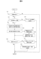
図6は、インバータ制御装置6による変形例に係る異常判定処理のフローチャートである。この変形例は、図5に示した異常判定処理のフローチャートに対し、平滑コンデンサの異常までの期間を予測するための処理(ステップS19およびステップS20)を追加したものである。図5に示した異常判定処理のフローチャートの処理と同一の処理には同一の符号を附して、その説明を簡略に行う。
Figure 6 is a flowchart of a modified abnormality determination process performed by the
変形例に係る異常判定処理は、図5と同様に、電力変換装置100が待機状態であること(ステップS11:Yes)、そして直流電圧検出器の出力が電力変換装置100の定格電圧と乖離していないこと(ステップS11:Nо)を判定した後に行われる。
The abnormality determination process according to the modified example is performed after determining that the
平滑コンデンサの異常判定処理において、中性点電圧指令発生器68は中性点電圧指令を中性点電圧制御器65に与え、中性点電圧制御器65は中性点電圧が中性点電圧指令に追従するように操作量を演算する(ステップS14)。その後、変動成分演算器66は、中性点電圧制御器65により演算された操作量の変動成分を抽出し(ステップS15)、平滑コンデンサ異常判定器67は抽出された操作量の変動成分に基づいて異常判定を行う(ステップS16)。
In the smoothing capacitor abnormality determination process, the neutral point
ここで、ステップS15において、変動成分演算器66は中性点電圧制御器65の操作量の変動成分を抽出した後、抽出された操作量の変動成分の値および変動成分を取得した時間を記憶部に記憶する(ステップS19)。記憶部には、図6に示す異常判定処理が行われる度に抽出される操作量の変動成分の値および変動成分を取得した時間が履歴として順次記憶される。
Here, in step S15, the
次に、記憶部に記憶されている履歴を読み出し、例えば、図4に示した操作量の変動成分の値と平滑コンデンサの劣化度合いとの関係を参照して、平滑コンデンサの劣化度合いが、c1~c2やc2以上になるまでの期間を予測する。そして、予測した期間を、例えば、交換推奨レベルまで2か月です、などと表示器70に表示する(ステップS20)。なお、記憶部に記憶されている履歴は、平滑コンデンサの交換時に削除する。もしくは、変動成分の値が急激に上昇したことを検出して、平滑コンデンサが交換されたとみなし、記憶部の履歴を自動的に削除する。なお、平滑コンデンサの劣化度合いを段階的に表示する例を説明したが、履歴に基づいて平滑コンデンサの異常発生までの期間を予測してこれを表示してもよい。
Next, the history stored in the memory unit is read out, and the period until the degree of deterioration of the smoothing capacitor reaches c1 to c2 or c2 or more is predicted, for example, by referring to the relationship between the value of the variable component of the operation amount and the deterioration degree of the smoothing capacitor shown in FIG. 4. The predicted period is then displayed on the
変形例によれば、平滑コンデンサの異常発生の時期を前もって把握することができ、異常発生の予防や異常発生時の対応の準備を予め行うことができる。 According to this modified example, it is possible to know in advance when an abnormality will occur in the smoothing capacitor, and to take steps to prevent the abnormality from occurring and to respond in the event of an abnormality occurring.
[第2実施形態]
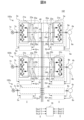
図7は、第2実施形態に係る電力変換装置101の全体構成図である。
図7に示す第2実施形態に係る電力変換装置101は、図1に示す第1実施形態に係る電力変換装置100のコンバータ制御装置5に、コンバータ側変動成分演算器56と、コンバータ側平滑コンデンサ異常判定器57と、コンバータ側中性点電圧指令発生器58とを備えた構成である。図1に示す第1実施形態に係る電力変換装置100と同一の箇所には同一の符号を附してその説明を省略する。
[Second embodiment]
FIG. 7 is an overall configuration diagram of a
A
電力変換装置101の待機状態において、コンバータ側の平滑コンデンサ22、23の異常判定処理を行う場合に、コンバータ側中性点電圧指令発生器58は、波形信号を成す中性点電圧指令を目標値としてコンバータ側中性点電圧制御器55へ入力する。
When the
コンバータ側中性点電圧制御器55は、中性点電圧指令に中性点電圧を追従させるための操作量を算出し、中性点電圧を制御する。コンバータ側変動成分演算器56は、コンバータ側中性点電圧制御器55より入力された操作量に基づいて、平滑コンデンサの異常判断時に、中性点電圧指令を波形信号で変化させたときの操作量の変動成分を抽出し、コンバータ側平滑コンデンサ異常判定器57に出力する。コンバータ側平滑コンデンサ異常判定器57は、操作量において、平滑コンデンサの異常発生時に生じる変動成分の変化に基づいて、コンバータP側平滑コンデンサ22およびコンバータN側平滑コンデンサ23の異常を判定する。この異常の判定手法は、図2~図6を参照して説明したインバータ側平滑コンデンサ32、33の異常判定と同様である。
The converter-side neutral
ここで、コンバータ側直流電圧検出器25、26の検出値から算出される中性点電圧と、インバータ側直流電圧検出器35、36の検出値から算出される中性点電圧は、コンバータ中性点抵抗24およびインバータ中性点抵抗34によって分離されている。したがって、中性点電圧は、コンバータ2とインバータ3で個別の値を有し、コンバータ側中性点電圧制御器55とインバータ側中性点電圧制御器65は、コンバータ側中性点電圧とインバータ側中性点電圧を個別に制御している。そのため、インバータ側平滑コンデンサ32、33の異常判定とコンバータ側平滑コンデンサ異常判定22、23は、互いに干渉することなく、個別に実施することができる。
Here, the neutral point voltage calculated from the detection values of the converter side
なお、インバータ側平滑コンデンサ32、33の異常判定は、図2~図6を参照して説明した第1実施形態と同様である。すなわち、インバータ側中性点電圧制御器65は、中性点電圧指令に中性点電圧を追従させるための操作量を算出し、中性点電圧を制御する。インバータ側平滑コンデンサ異常判定器67は、操作量の変動成分の値に基づいて、インバータP側平滑コンデンサ32およびインバータN側平滑コンデンサ33の異常を判定する。
The abnormality determination for the inverter
コンバータ側平滑コンデンサ異常判定器57およびインバータ側平滑コンデンサ異常判定器67は、異常がある平滑コンデンサを検出した場合には、異常に関する情報(例えば、異常のある平滑コンデンサを特定できる情報(例えば、コンバータ側のデバイス番号、インバータ側のデバイス番号))と、点検・交換等を推奨するメッセージとを表示器70に表示する。
When the converter side smoothing
前述したように、中性点電圧を制御する操作量は、目標値とする波形信号の周波数と振幅や正常時の平滑コンデンサ容量、制御応答によってその変動成分が増減する。従って、インバータ3とコンバータ2の平滑コンデンサ容量が異なる場合や、制御応答が異なる場合は、コンバータ側中性点電圧制御器55とインバータ側中性点電圧制御器65において目標値とする波形信号の周波数と振幅は、個別の値を設定することが望ましい。
As mentioned above, the fluctuating components of the manipulated variable that controls the neutral point voltage increase or decrease depending on the frequency and amplitude of the waveform signal that is the target value, the smoothing capacitor capacity under normal conditions, and the control response. Therefore, if the smoothing capacitor capacity of the
本実施形態によれば、インバータ側の平滑コンデンサ32、33の異常判定のみならず、コンバータ側の平滑コンデンサ22、23の異常判定も実施でき、操作量の変動成分の値と平滑コンデンサの劣化度合いは直線的な関係にあるので、操作量の変動成分によりインバータ側の平滑コンデンサおよびコンバータ側の平滑コンデンサの異常を精度よく検出することが可能となる。
According to this embodiment, it is possible to perform abnormality determination not only for the smoothing
[第3実施形態]
図8は、第3実施形態に係る電力変換装置102の全体構成図である。
図8に示す第3実施形態に係る電力変換装置102は、図7に示す第2実施形態に係る電力変換装置101を複数個並列に設けた構成である。図7に示す第2実施形態に係る電力変換装置101と同一の箇所には同一の符号を附してその説明を省略する。
[Third embodiment]
FIG. 8 is an overall configuration diagram of a
A
電力変換装置102の一つ(第1電力変換装置102aと表記する場合がある)は、第2実施形態に係る電力変換装置101と同様に、交流電源1aからの交流電力を直流電力に変換するコンバータユニット2aと、コンバータユニット2aが出力する直流電力を所望の交流電力に変換するインバータユニット3aと、コンバータユニット2aを制御するコンバータ制御装置5aと、インバータユニット3aを制御するインバータ制御装置6aと、を備え、インバータユニット3aが出力する交流電力により電動機4aが駆動される。電力変換装置102は、このような第1電力変換装置102aを複数個並列(第1電力変換装置102a、第2電力変換装置102b、第3電力変換装置102c、・・・)に設けて構成される。
One of the power conversion devices 102 (sometimes referred to as the first
各電力変換装置102a、102b、102c、・・・のP配線40、C配線41、N配線42は各々共通の線で接続されている。また、表示器70は、各電力変換装置102a、102b、102c、・・・から出力される平滑コンデンサの異常に関する情報を表示する。
The
コンバータ制御装置5a、5b、5c、・・・の構成は、図7を参照して説明したコンバータ制御装置5と同様である。インバータ制御装置6a、6b、6c、・・・の構成は、図1を参照して説明したインバータ制御装置6と同様である。
The configuration of the
コンバータ制御装置5a、5b、5c、・・・は、コンバータ側中性点電圧制御器55(55a、55b、55c、・・・)と、コンバータ側平滑コンデンサ異常判定器57(57a、57b、57c、・・・)と、コンバータ側中性点電圧指令発生器58(58a、58b、58c、・・・)とを備える。そして、コンバータ側中性点電圧制御器55(55a、55b、55c、・・・)の操作量の変動成分に基づいてコンバータP側平滑コンデンサ22(22a、22b、22c、・・・)およびコンバータN側平滑コンデンサ23(23a、23b、23c、・・・)の異常を判定する。
The
インバータ制御装置6a、6b、6c、・・・は、インバータ側中性点電圧制御器65(65a、65b、65c、・・・)と、インバータ側平滑コンデンサ異常判定器67(67a、67b、67c、・・・)と、インバータ側中性点電圧指令発生器68(68a、68b、68c、・・・)とを備える。そして、インバータ側中性点電圧制御器65(65a、65b、65c、・・・)の操作量の変動成分に基づいてインバータP側平滑コンデンサ32(32a、32b、32c、・・・)およびインバータN側平滑コンデンサ33(33a、33b、33c、・・・)の異常を判定する。
The
電力変換装置102において、中性点電圧は、コンバータ中性点抵抗24(24a、24b、24c、・・・)とインバータ中性点抵抗34(34a、34b、34c、・・・)によって、コンバータユニット2(2a、2b、2c、・・・)とインバータユニット3(3a、3b、3c、・・・)に中性点電圧が分離されており、異なる中性点電圧を有する。このため、電力変換装置102のように複数のコンバータまたはインバータが並列に接続された構成でも、コンバータユニット2およびインバータユニット3の平滑コンデンサの異常判定を適切に行うことができる。
In the
また、コンバータ側平滑コンデンサ異常判定器57(57a、57b、57c、・・・)およびインバータ側平滑コンデンサ異常判定器67(67a、67b、67c、・・・)において、関係する平滑コンデンサが異常であると判定した場合には、異常である平滑コンデンサを特定する情報、例えば、デバイス番号を表示器70へ出力する。
In addition, when the converter side smoothing capacitor abnormality determiner 57 (57a, 57b, 57c, ...) and the inverter side smoothing capacitor abnormality determiner 67 (67a, 67b, 67c, ...) determine that the relevant smoothing capacitor is abnormal, information identifying the abnormal smoothing capacitor, such as the device number, is output to the
本実施形態によれば、各コンバータユニット2(2a、2b、2c、・・・)またはインバータユニット3(3a、3b、3c、・・・)の異常と判定された平滑コンデンサの位置を、各ユニット単位で特定できる。また、操作量の変動成分の値と平滑コンデンサの劣化度合いは直線的な関係にあるので、操作量の変動成分の値により各ユニットの平滑コンデンサの異常を精度よく検出することが可能となる。 According to this embodiment, the position of the smoothing capacitor determined to be abnormal in each converter unit 2 (2a, 2b, 2c, ...) or inverter unit 3 (3a, 3b, 3c, ...) can be identified for each unit. In addition, since there is a linear relationship between the value of the fluctuation component of the manipulated variable and the degree of deterioration of the smoothing capacitor, it is possible to accurately detect an abnormality in the smoothing capacitor of each unit based on the value of the fluctuation component of the manipulated variable.
第1実施形態から第3実施形態では、コンバータ制御装置5やインバータ制御装置6はブロック構成図で説明したが、各ブロックの一部もしくは全部をプロセッサとプログラムによってその機能を実現するようにしてもよい。この場合、例えば、図5、図6のフローチャートで示した処理、等の処理を実行するプログラムは、プロセッサ(例えばCPU、GPU)によって実行される。これらの処理は、適宜に記憶資源(例えばメモリ)および/またはインターフェースデバイス(例えば通信ポート)等を用いながら行う。また、プログラムを実行して行う処理の主体が、プロセッサを有するコントローラ、装置、システム、計算機、ノードであってもよい。プログラムを実行して行う処理の主体は、演算部であれば良く、特定の処理を行う専用回路(例えばFPGAやASIC)を含んでいてもよい。
In the first to third embodiments, the
以上説明した実施形態によれば、次の作用効果が得られる。
(1)電力変換装置100、101、102は、交流電圧を正電位と、負電位と、正電位と負電位の中間の中性点電位との3つの電位を有する直流電圧に変換する、または3つの電位を有する直流電圧を交流電圧に変換する電力変換回路21、31と、正電位と中性点電位との間、および中性点電位と負電位との間にそれぞれ接続された平滑コンデンサ22、23、32、33と、平滑コンデンサ22、23、32、33が接続された各電位間の電圧を検出する直流電圧検出器25、26、35、36と、電力変換回路を制御する制御部(コンバータ制御装置5、インバータ制御装置6)と、を備え、制御部(コンバータ制御装置5、インバータ制御装置6)は、直流電圧検出器25、26、35、36の検出値と中性点電位を中性点電圧指令に追従させる操作量とに基づいて中性点電位を制御し、操作量の変動成分により平滑コンデンサ22、23、32、33の異常を判定する。これにより、電力変換装置における平滑コンデンサの異常を精度よく検出することが可能となる。
According to the embodiment described above, the following advantageous effects can be obtained.
(1)
(2)異常判定方法は、交流電圧を正電位と、負電位と、正電位と前記負電位の中間の中性点電位との3つの電位を有する直流電圧に変換する、または3つの電位を有する直流電圧を交流電圧に変換する電力変換回路21、31と、正電位と中性点電位との間、および中性点電位と負電位との間にそれぞれ接続された平滑コンデンサ22、23、32、33と、平滑コンデンサ22、23、32、33が接続された各電位間の電圧を検出する直流電圧検出器25、26、35、36と、電力変換回路21、31を制御する制御部(コンバータ制御装置5、インバータ制御装置6)と、を備える電力変換装置100、101、102における平滑コンデンサ22、23、32、33の異常判定方法であって、直流電圧検出器25、26、35、36の検出値と中性点電位を中性点電圧指令に追従させる操作量とに基づいて中性点電位を制御し、操作量の変動成分により平滑コンデンサ22、23、32、33の異常を判定する。これにより、電力変換装置における平滑コンデンサの異常を精度よく検出することが可能となる。
(2) The abnormality determination method includes
(変形例)
本発明は、以上説明した第1~第3の実施形態を次のように変形して実施することができる。
(1)電力変換装置100は、交流電源1からの交流電力を直流電力に変換するコンバータユニット2と、コンバータユニット2が出力する直流電力を所望の交流電力に変換するインバータユニット3とを備えた例で説明した。しかし、電力変換装置100は、コンバータユニット2もしくはインバータユニット3の何れかを備えた構成であってもよい。インバータユニット3のみを備えた電力変換装置100は、例えば、バッテリ等の直流電源より供給される直流電力を所望の交流電力に変換する。
(Modification)
The present invention can be carried out by modifying the above-described first to third embodiments as follows.
(1) The
本発明は、上述の実施形態に限定されるものではなく、本発明の特徴を損なわない限り、本発明の技術思想の範囲内で考えられるその他の形態についても、本発明の範囲内に含まれる。また、上述の各実施形態と複数の変形例を組み合わせた構成としてもよい。 The present invention is not limited to the above-described embodiments, and other forms that are conceivable within the scope of the technical concept of the present invention are also included within the scope of the present invention, so long as they do not impair the characteristics of the present invention. In addition, the above-described embodiments may be combined with multiple modified examples.
2…コンバータユニット、3…インバータユニット、4…電動機、5…コンバータ制御装置、6…インバータ制御装置、21、31…電力変換回路、22…コンバータP側平滑コンデンサ、23…コンバータN側平滑コンデンサ、24…コンバータ中性点抵抗、25…コンバータP側直流電圧検出器、26…コンバータN側直流電圧検出器、32…インバータP側平滑コンデンサ、33…インバータN側平滑コンデンサ、34…インバータ中性点抵抗、35…インバータP側直流電圧検出器、36…インバータN側直流電圧検出器、55…コンバータ側中性点電圧制御器、56…コンバータ側変動成分演算器、57…コンバータ側平滑コンデンサ異常判定器、58…コンバータ側中性点電圧指令発生器、65…インバータ側中性点電圧制御器、66…インバータ側変動成分演算器、67…インバータ側平滑コンデンサ異常判定器、68…インバータ側中性点電圧指令発生器、70…表示器、100、101、102…電力変換装置。 2...Converter unit, 3...Inverter unit, 4...Electric motor, 5...Converter control device, 6...Inverter control device, 21, 31...Power conversion circuit, 22...Converter P-side smoothing capacitor, 23...Converter N-side smoothing capacitor, 24...Converter neutral point resistance, 25...Converter P-side DC voltage detector, 26...Converter N-side DC voltage detector, 32...Inverter P-side smoothing capacitor, 33...Inverter N-side smoothing capacitor, 34...Inverter neutral point resistance, 35...Inverter inverter P-side DC voltage detector, 36... inverter N-side DC voltage detector, 55... converter side neutral point voltage controller, 56... converter side fluctuation component calculator, 57... converter side smoothing capacitor abnormality determiner, 58... converter side neutral point voltage command generator, 65... inverter side neutral point voltage controller, 66... inverter side fluctuation component calculator, 67... inverter side smoothing capacitor abnormality determiner, 68... inverter side neutral point voltage command generator, 70... display, 100, 101, 102... power conversion device.
Claims (13)
前記正電位と前記中性点電位との間、および前記中性点電位と前記負電位との間にそれぞれ接続された平滑コンデンサと、
前記平滑コンデンサが接続された各電位間の電圧を検出する直流電圧検出器と、
前記電力変換回路を制御する制御部と、を備え、
前記制御部は、前記直流電圧検出器の検出値と前記中性点電位を中性点電圧指令に追従させる操作量とに基づいて前記中性点電位を制御し、前記操作量の変動成分により前記平滑コンデンサの異常を判定する電力変換装置。 a power conversion circuit that converts an AC voltage into a DC voltage having three potentials, namely a positive potential, a negative potential, and a neutral point potential intermediate between the positive potential and the negative potential, or converts a DC voltage having the three potentials into an AC voltage;
smoothing capacitors connected between the positive potential and the neutral point potential, and between the neutral point potential and the negative potential;
a DC voltage detector for detecting a voltage between each potential to which the smoothing capacitor is connected;
A control unit that controls the power conversion circuit,
The control unit controls the neutral point potential based on the detection value of the DC voltage detector and an operating variable that causes the neutral point potential to follow a neutral point voltage command, and determines whether or not there is an abnormality in the smoothing capacitor based on the fluctuation component of the operating variable.
前記制御部は、
前記中性点電圧指令を発生する中性点電圧指令発生器と、
前記中性点電圧指令発生器より入力される中性点電圧指令値と前記直流電圧検出器より検出される中性点電圧との差に基づいて、前記操作量を演算する中性点電圧制御器と、を備え、
前記制御部は、前記中性点電圧制御器により演算された前記操作量の前記変動成分を抽出して、前記変動成分の値に基づいて前記平滑コンデンサの異常を判定する電力変換装置。 2. The power conversion device according to claim 1,
The control unit is
a neutral point voltage command generator that generates the neutral point voltage command;
a neutral point voltage controller that calculates the manipulated variable based on a difference between a neutral point voltage command value input from the neutral point voltage command generator and a neutral point voltage detected by the DC voltage detector,
The control unit extracts the fluctuation component of the manipulated variable calculated by the neutral point voltage controller, and determines whether or not there is an abnormality in the smoothing capacitor based on the value of the fluctuation component.
前記中性点電圧指令発生器は、前記中性点電圧指令として波形信号を発生する電力変換装置。 3. The power conversion device according to claim 2,
The neutral point voltage command generator is a power conversion device that generates a waveform signal as the neutral point voltage command.
前記制御部は、前記操作量の前記変動成分の値と基準値との差が、所定の閾値を超えている場合に、平滑コンデンサが異常であると判定する電力変換装置。 3. The power conversion device according to claim 2,
The control unit determines that a smoothing capacitor is abnormal when a difference between a value of the fluctuation component of the manipulated variable and a reference value exceeds a predetermined threshold.
前記制御部は、前記変動成分の値に応じて前記平滑コンデンサの劣化の度合いを判定し、前記判定した前記劣化の度合いに応じた情報を表示器に表示する電力変換装置。 The power conversion device according to claim 4,
The control unit determines a degree of deterioration of the smoothing capacitor according to the value of the fluctuation component, and displays information according to the determined degree of deterioration on a display.
前記制御部は、前記中性点電圧制御器より入力される前記操作量の前記変動成分の値を履歴として記憶し、前記記憶した前記履歴に基づいて、前記平滑コンデンサの異常発生までの期間を予測して、その予測結果を表示器に表示する電力変換装置。 3. The power conversion device according to claim 2,
The control unit stores the value of the fluctuation component of the manipulated variable input from the neutral point voltage controller as history, predicts the period until an abnormality occurs in the smoothing capacitor based on the stored history, and displays the prediction result on a display.
前記電力変換回路は、前記交流電圧を前記直流電圧に変換するコンバータ、または前記直流電圧を前記交流電圧に変換するインバータである電力変換装置。 In the power conversion device according to any one of claims 1 to 6,
The power conversion circuit is a power conversion device that is a converter that converts the AC voltage into the DC voltage, or an inverter that converts the DC voltage into the AC voltage.
前記電力変換回路は、前記コンバータと前記インバータとを接続して構成され、前記コンバータおよび前記インバータは前記中性点電位を前記インバータ側と前記コンバータ側とに分離する中性点抵抗器を備え、
前記制御部は、前記コンバータを制御する第1制御部と、前記インバータを制御する第2制御部とを備え、
前記第1制御部は、前記中性点抵抗器によって分離された前記コンバータ側の前記中性点電位を前記操作量に基づいて制御して前記コンバータ側の前記平滑コンデンサの異常を判定し、
前記第2制御部は、前記中性点抵抗器によって分離された前記インバータ側の前記中性点電位を前記操作量に基づいて制御して前記インバータ側の前記平滑コンデンサの異常を判定する電力変換装置。 The power conversion device according to claim 7,
the power conversion circuit is configured by connecting the converter and the inverter, the converter and the inverter each including a neutral point resistor that divides the neutral point potential into an inverter side and a converter side;
The control unit includes a first control unit that controls the converter and a second control unit that controls the inverter,
the first control unit controls the neutral point potential of the converter side separated by the neutral point resistor based on the manipulated variable to determine an abnormality of the smoothing capacitor of the converter side;
The second control unit is a power conversion device that determines an abnormality in the smoothing capacitor on the inverter side by controlling the neutral point potential on the inverter side separated by the neutral point resistor based on the manipulated variable.
前記電力変換回路は、並列に複数個設けられ、
前記制御部は、各電力変換回路に対応してそれぞれ設けられ、前記コンバータ側または前記インバータ側の前記平滑コンデンサの異常を判定する電力変換装置。 The power conversion device according to claim 7,
The power conversion circuit is provided in a plurality of units in parallel,
The control unit is provided corresponding to each power conversion circuit, and is a power conversion device that determines an abnormality in the smoothing capacitor on the converter side or the inverter side.
前記電力変換回路は、並列に複数個設けられ、
前記制御部は、各電力変換回路に対応してそれぞれ設けられ、前記コンバータ側または前記インバータ側の前記平滑コンデンサの異常を判定する電力変換装置。 9. The power converter according to claim 8,
The power conversion circuit is provided in a plurality of units in parallel,
The control unit is provided corresponding to each power conversion circuit, and is a power conversion device that determines an abnormality in the smoothing capacitor on the converter side or the inverter side.
前記電力変換回路は、前記直流電圧を前記交流電圧に変換して電動機を駆動するインバータであり、
前記制御部は、前記電動機の待機状態において、前記平滑コンデンサの異常を判定する電力変換装置。 The power conversion device according to claim 7,
the power conversion circuit is an inverter that converts the DC voltage into the AC voltage to drive an electric motor,
The control unit is configured to determine an abnormality in the smoothing capacitor when the motor is in a standby state.
前記電力変換回路は、前記直流電圧を前記交流電圧に変換して電動機を駆動するインバータであり、
前記制御部は、前記電動機の待機状態において、前記平滑コンデンサの異常を判定する電力変換装置。 9. The power converter according to claim 8,
the power conversion circuit is an inverter that converts the DC voltage into the AC voltage to drive an electric motor,
The control unit is configured to determine an abnormality in the smoothing capacitor when the motor is in a standby state.
前記正電位と前記中性点電位との間、および前記中性点電位と前記負電位との間にそれぞれ接続された平滑コンデンサと、
前記平滑コンデンサが接続された各電位間の電圧を検出する直流電圧検出器と、
前記電力変換回路を制御する制御部と、を備える電力変換装置における平滑コンデンサの異常判定方法であって、
前記直流電圧検出器の検出値と前記中性点電位を中性点電圧指令に追従させる操作量とに基づいて前記中性点電位を制御し、前記操作量の変動成分により前記平滑コンデンサの異常を判定する異常判定方法。
a power conversion circuit that converts an AC voltage into a DC voltage having three potentials, namely a positive potential, a negative potential, and a neutral point potential intermediate between the positive potential and the negative potential, or converts a DC voltage having the three potentials into an AC voltage;
smoothing capacitors connected between the positive potential and the neutral point potential, and between the neutral point potential and the negative potential;
a DC voltage detector for detecting a voltage between each potential connected to the smoothing capacitor;
A method for determining an abnormality of a smoothing capacitor in a power conversion device including a control unit that controls the power conversion circuit,
An abnormality determination method for controlling the neutral point potential based on the detection value of the DC voltage detector and an operating variable that causes the neutral point potential to follow a neutral point voltage command, and determining an abnormality in the smoothing capacitor based on the fluctuation component of the operating variable.
Priority Applications (1)
| Application Number | Priority Date | Filing Date | Title |
|---|---|---|---|
| JP2021155865A JP7588570B2 (en) | 2021-09-24 | 2021-09-24 | Power conversion device and abnormality determination method |
Applications Claiming Priority (1)
| Application Number | Priority Date | Filing Date | Title |
|---|---|---|---|
| JP2021155865A JP7588570B2 (en) | 2021-09-24 | 2021-09-24 | Power conversion device and abnormality determination method |
Publications (2)
| Publication Number | Publication Date |
|---|---|
| JP2023046987A JP2023046987A (en) | 2023-04-05 |
| JP7588570B2 true JP7588570B2 (en) | 2024-11-22 |
Family
ID=85778272
Family Applications (1)
| Application Number | Title | Priority Date | Filing Date |
|---|---|---|---|
| JP2021155865A Active JP7588570B2 (en) | 2021-09-24 | 2021-09-24 | Power conversion device and abnormality determination method |
Country Status (1)
| Country | Link |
|---|---|
| JP (1) | JP7588570B2 (en) |
Citations (2)
| Publication number | Priority date | Publication date | Assignee | Title |
|---|---|---|---|---|
| JP2008011606A (en) | 2006-06-28 | 2008-01-17 | Hitachi Ltd | Power conversion device and power conversion method |
| JP2010233425A (en) | 2009-03-30 | 2010-10-14 | Fujitsu General Ltd | Capacitor deterioration detection circuit and electronic device equipped with the same |
Family Cites Families (1)
| Publication number | Priority date | Publication date | Assignee | Title |
|---|---|---|---|---|
| JP3173376B2 (en) * | 1996-06-14 | 2001-06-04 | 株式会社日立製作所 | Apparatus for determining the capacitance of a capacitor of a three-level power converter |
-
2021
- 2021-09-24 JP JP2021155865A patent/JP7588570B2/en active Active
Patent Citations (2)
| Publication number | Priority date | Publication date | Assignee | Title |
|---|---|---|---|---|
| JP2008011606A (en) | 2006-06-28 | 2008-01-17 | Hitachi Ltd | Power conversion device and power conversion method |
| JP2010233425A (en) | 2009-03-30 | 2010-10-14 | Fujitsu General Ltd | Capacitor deterioration detection circuit and electronic device equipped with the same |
Also Published As
| Publication number | Publication date |
|---|---|
| JP2023046987A (en) | 2023-04-05 |
Similar Documents
| Publication | Publication Date | Title |
|---|---|---|
| KR102294575B1 (en) | Sensor fault diagnosis system for converter | |
| US9608534B2 (en) | Power conversion system, and voltage detection device thereof | |
| KR101823140B1 (en) | Method for detecting inverter fault and apparatus thereof | |
| JP6895921B2 (en) | Power converter and abnormality detection method | |
| JP5896964B2 (en) | Electronic control unit | |
| WO2011040411A1 (en) | Voltage monitoring apparatus | |
| US20210057997A1 (en) | Power supply device | |
| JP4466618B2 (en) | Power conversion device and power conversion method | |
| JP6817881B2 (en) | Power converter and abnormality detection method | |
| JP7588570B2 (en) | Power conversion device and abnormality determination method | |
| JP6417256B2 (en) | Electric motor drive | |
| JP2020156207A (en) | Multiphase converter | |
| WO2020157919A1 (en) | Machine learning device and motor control system | |
| US10797512B2 (en) | Uninterruptible power supply | |
| JP2019195231A (en) | Electric power conversion system and abnormality detection method | |
| JP5242980B2 (en) | Capacitor failure detection circuit and power supply device | |
| JP2017112792A (en) | Capacitor deterioration diagnosis method and power converter | |
| JP2008172910A (en) | Power converter | |
| US9823278B2 (en) | Fault detecting apparatus and computer program therefor | |
| JP7499198B2 (en) | Power conversion device and abnormality detection method | |
| JP7631078B2 (en) | Power conversion device and electric motor control method | |
| JP5876748B2 (en) | Converter device | |
| JP6984288B2 (en) | Power converter | |
| JP6988300B2 (en) | Three-phase inverter device | |
| CN116961439A (en) | power conversion device |
Legal Events
| Date | Code | Title | Description |
|---|---|---|---|
| A621 | Written request for application examination |
Free format text: JAPANESE INTERMEDIATE CODE: A621 Effective date: 20240226 |
|
| A977 | Report on retrieval |
Free format text: JAPANESE INTERMEDIATE CODE: A971007 Effective date: 20241023 |
|
| TRDD | Decision of grant or rejection written | ||
| A01 | Written decision to grant a patent or to grant a registration (utility model) |
Free format text: JAPANESE INTERMEDIATE CODE: A01 Effective date: 20241029 |
|
| A61 | First payment of annual fees (during grant procedure) |
Free format text: JAPANESE INTERMEDIATE CODE: A61 Effective date: 20241112 |
|
| R150 | Certificate of patent or registration of utility model |
Ref document number: 7588570 Country of ref document: JP Free format text: JAPANESE INTERMEDIATE CODE: R150 |