JP7586877B2 - Method for dismantling and assembling a wind turbine - Google Patents

Method for dismantling and assembling a wind turbine Download PDF

Info

Publication number
JP7586877B2
JP7586877B2 JP2022169172A JP2022169172A JP7586877B2 JP 7586877 B2 JP7586877 B2 JP 7586877B2 JP 2022169172 A JP2022169172 A JP 2022169172A JP 2022169172 A JP2022169172 A JP 2022169172A JP 7586877 B2 JP7586877 B2 JP 7586877B2
Authority
JP
Japan
Prior art keywords
frame
tower
nacelle
wind turbine
lifting
Prior art date
Legal status (The legal status is an assumption and is not a legal conclusion. Google has not performed a legal analysis and makes no representation as to the accuracy of the status listed.)
Active
Application number
JP2022169172A
Other languages
Japanese (ja)
Other versions
JP2024061311A (en
Inventor
魁 水上
孝之 落合
延光 長井
Current Assignee (The listed assignees may be inaccurate. Google has not performed a legal analysis and makes no representation or warranty as to the accuracy of the list.)
Taihei Dengyo Kaisha Ltd
Original Assignee
Taihei Dengyo Kaisha Ltd
Priority date (The priority date is an assumption and is not a legal conclusion. Google has not performed a legal analysis and makes no representation as to the accuracy of the date listed.)
Filing date
Publication date
Application filed by Taihei Dengyo Kaisha Ltd filed Critical Taihei Dengyo Kaisha Ltd
Priority to JP2022169172A priority Critical patent/JP7586877B2/en
Publication of JP2024061311A publication Critical patent/JP2024061311A/en
Application granted granted Critical
Publication of JP7586877B2 publication Critical patent/JP7586877B2/en
Active legal-status Critical Current
Anticipated expiration legal-status Critical

Links

Images

Classifications

    • YGENERAL TAGGING OF NEW TECHNOLOGICAL DEVELOPMENTS; GENERAL TAGGING OF CROSS-SECTIONAL TECHNOLOGIES SPANNING OVER SEVERAL SECTIONS OF THE IPC; TECHNICAL SUBJECTS COVERED BY FORMER USPC CROSS-REFERENCE ART COLLECTIONS [XRACs] AND DIGESTS
    • Y02TECHNOLOGIES OR APPLICATIONS FOR MITIGATION OR ADAPTATION AGAINST CLIMATE CHANGE
    • Y02EREDUCTION OF GREENHOUSE GAS [GHG] EMISSIONS, RELATED TO ENERGY GENERATION, TRANSMISSION OR DISTRIBUTION
    • Y02E10/00Energy generation through renewable energy sources
    • Y02E10/70Wind energy
    • Y02E10/72Wind turbines with rotation axis in wind direction

Landscapes

  • Wind Motors (AREA)

Description

本発明は、風力発電等に用いられる風車の解体又は組み立てに係る施工方法等に関するものである。 The present invention relates to a construction method for dismantling or assembling a wind turbine used for wind power generation, etc.

特許文献1には、風力発電に用いられる風車の施工方法が開示されている。特許文献1の施工方法では、特許文献1の図1等に示すように、風車のタワーの横に自己昇降式作業台を構築し、その上に自走式クレーンを配置し、自走式クレーンを用いて風車の施工を行う。 Patent Document 1 discloses a construction method for a wind turbine used for wind power generation. In the construction method of Patent Document 1, as shown in FIG. 1 of Patent Document 1, a self-elevating work platform is constructed next to the tower of the wind turbine, a self-propelled crane is placed on top of the platform, and the wind turbine is constructed using the self-propelled crane.

特開2019-152120号公報JP 2019-152120 A

しかしながら、風車が設置される山間部において風車の解体を行うための施工スペースは限られており、自己昇降式作業台を設置することが困難な場合がある。また、自走式クレーンに代えて超大型の非自走式クレーンを用いるとしても、クレーンの組立、解体、設置スペース、風車タワー下架後の解体スペースを考慮すると広大な作業スペースが必要となる。更に、大型クレーンや大型のトレーラーが通行する為の搬入路の整備や地盤整備のために多くの木々を切り開くこととなり、多大な時間と費用が掛かることもある。 However, in mountainous areas where wind turbines are installed, the construction space required for dismantling the turbines is limited, and it can be difficult to install a self-elevating work platform. Even if an extra-large non-self-propelled crane is used instead of a self-propelled crane, a large work space is required when considering the space required for assembling, dismantling and setting up the crane, and for dismantling the wind turbine tower after it is lowered. Furthermore, many trees must be cut down to prepare access roads and ground for large cranes and large trailers to pass through, which can be very time-consuming and costly.

本発明は、こうした事情を鑑み、狭小な土地において巨大な風車の施工を可能とする風車施工用架台を用いた風車の施工方法等を提供することを目的とする。 In view of these circumstances, the present invention aims to provide a wind turbine construction method using a wind turbine construction stand that enables the construction of a large wind turbine on a small piece of land.

この発明は、上記目的を達成するためになされたものであって、下記を特徴とするものである。 This invention has been made to achieve the above objective and has the following features:

請求項1記載の発明は、風車のタワーを囲う位置に構築される第1架台と、前記タワーを囲う位置であって前記第1架台の外側に構築される第2架台と、前記第2架台に設けられ、前記第1架台を昇降させる架台用昇降手段と、前記第1架台に設けられ、前記タワーを構成する複数のタワー部材のうち最下段にある前記タワー部材より上にあるその他の前記タワー部材を吊った状態で昇降させる第1昇降手段と、前記第1架台に設けられ、前記最下段にあるタワー部材を吊った状態で昇降させる第2昇降手段と、を備え、前記第1架台が、その頂部に、最上段の前記タワー部材の上部に設置されたナセルを載置可能な載置部を有する風車施工用架台を用いた前記風車の解体方法であって、前記最下段にあるタワー部材と、最下段から一段上にある前記タワー部材を分割する分割工程と、前記第1架台が前記第2架台に対してせり上がった状態で、前記第1昇降手段により前記最下段にあるタワー部材より上にある前記風車の部材の荷重を支持する支持工程と、前記支持工程により荷重を支持している状態で、前記第2昇降手段により前記最下段にあるタワー部材を支持しつつ、前記風車施工用架台から搬出する搬出工程と、前記搬出工程の後に、前記第1昇降手段により前記その他のタワー部材を下降させる風車部材下降工程と、前記風車部材下降工程により前記ナセルが前記載置部に載置された場合に、前記最上段のタワー部材と前記ナセルを切り離す切り離し工程と、前記ナセルが前記載置部に載置された状態で、前記架台用昇降手段がせり上がった状態の前記第1架台を下降させる架台下降工程と、前記架台下降工程の後に、前記ナセルが前記載置部に載置された状態で、前記第1架台の上部を残して下部を解体する第1架台解体工程と、前記第1架台解体工程の後に、前記ナセルが前記載置部に載置された状態で、前記架台用昇降手段が前記第1架台の上部を更に下降させる架台上部下降工程と、を含むことを特徴とする。 The invention described in claim 1 is a method for dismantling a wind turbine using a wind turbine construction stand comprising: a first stand constructed in a position surrounding a wind turbine tower; a second stand constructed outside the first stand in a position surrounding the tower; a stand lifting means provided on the second stand for lifting and lowering the first stand; a first lifting means provided on the first stand for lifting and lowering the other tower members above the lowest tower member among the multiple tower members constituting the tower while suspending them; and a second lifting means provided on the first stand for lifting and lowering the tower member at the lowest level while suspending them. The first stand has a mounting portion at its top on which a nacelle installed on the top of the tower member at the highest level can be placed, and the method includes a division process for dividing the tower member at the lowest level and the tower member one level above the lowest level, and a step of lifting and lowering the tower member at the lowest level by the first lifting means while the first stand is raised above the second stand. a supporting step of supporting a load of wind turbine components; a carrying-out step of carrying out the lowest tower component from the wind turbine construction frame while supporting the lowest tower component with the second lifting means while the load is being supported by the supporting step; a wind turbine component lowering step of lowering the other tower components with the first lifting means after the carrying-out step; a separation step of separating the highest tower component from the nacelle when the nacelle is placed on the placement section by the wind turbine component lowering step; The method includes a platform lowering step in which the platform lifting means lowers the first platform in a raised state while the nacelle is placed on the placement section; a first platform dismantling step in which, after the platform lowering step, the lower part of the first platform is dismantled while leaving the upper part while the nacelle is placed on the placement section; and an upper part of platform lowering step in which, after the first platform dismantling step, the platform lifting means further lowers the upper part of the first platform while the nacelle is placed on the placement section.

請求項2に記載の発明は、請求項1に記載の風車の解体方法であって、前記架台上部下降工程の前に、前記第1架台の上部を下降させる際に干渉する、前記第2架台の部材を撤去する撤去工程を更に含むことを特徴とする。 The invention described in claim 2 is the wind turbine dismantling method described in claim 1, characterized in that it further includes a removal step of removing a member of the second frame that interferes when the upper part of the first frame is lowered before the upper frame lowering step.

請求項3に記載の発明は、風車のタワーを囲う位置に構築される第1架台と、前記タワーを囲う位置であって前記第1架台の外側に構築される第2架台と、前記第2架台に設けられ、前記第1架台を昇降させる架台用昇降手段と、前記第1架台に設けられ、前記タワーを構成する複数のタワー部材のうち一部の前記タワー部材を吊った状態で昇降させる第1昇降手段と、前記第1架台に設けられ、前記一部のタワー部材より下に配置されるその他の前記タワー部材を吊った状態で昇降させる第2昇降手段と、を備え、前記第1架台が、その頂部に、最上段の前記タワー部材の上部に設置されたナセルを載置可能な載置部を有する風車施工用架台を用いた前記風車の組立方法であって、前記載置部を有する、前記第1架台の上部を構築する架台上部構築工程と、前記ナセルが前記載置部に載置された状態で、前記架台用昇降手段が前記第1架台の上部を上昇させる架台上部上昇工程と、前記架台上部上昇工程の後に、前記第1架台の上部に対して前記第1架台の下部を構築する架台下部構築工程と、前記架台下部構築工程の後に、前記ナセルが前記載置部に載置された状態で、前記架台用昇降手段が、前記第1架台を上昇させる架台上昇工程と、前記架台上昇工程の後に、前記第1昇降手段により最上段の前記タワー部材を前記ナセルと接合可能な位置まで吊り上げ、前記最上段のタワー部材と前記ナセルを接合するナセル接合工程と、前記第1架台が前記第2架台に対してせり上がった状態で、前記第1昇降手段により前記一部のタワー部材を吊り上げる吊り上げ工程と、前記第1昇降手段により吊り上げられた前記一部のタワー部材の下方に、前記第2昇降手段により前記その他のタワー部材を吊った状態で配置する配置工程と、前記第1昇降手段により前記一部のタワー部材を下降させ、前記配置工程で配置された前記その他のタワー部材の上に載置する載置工程と、前記載置工程の後に、前記一部のタワー部材と前記その他のタワー部材を接合するタワー部材接合工程と、を含むことを特徴とする。 The invention described in claim 3 includes a first frame constructed in a position surrounding a wind turbine tower, a second frame constructed outside the first frame in a position surrounding the tower, a frame lifting means provided on the second frame for raising and lowering the first frame, a first lifting means provided on the first frame for raising and lowering some of the tower members among a plurality of tower members constituting the tower in a suspended state, and a second lifting means provided on the first frame for raising and lowering the other tower members arranged below the some of the tower members in a suspended state. a second lifting means for lifting and lowering the upper part of the first frame with a second lifting means, and the first frame having a mounting portion on the top of the uppermost tower member, on which a nacelle installed on the upper part of the tower member at the highest stage can be placed, the method for assembling the wind turbine using a wind turbine construction frame comprising the steps of: a frame upper part construction step for constructing an upper part of the first frame having the mounting portion; a frame upper part raising step for raising the upper part of the first frame with the frame lifting means while the nacelle is placed on the mounting portion; The method includes a frame lower construction step for constructing the lower part of the stand, a frame lifting step for lifting the first frame with the frame lifting means while the nacelle is placed on the placement section after the frame lower construction step, a frame lifting step for lifting the topmost tower member with the first lifting means to a position where it can be joined with the nacelle after the frame lifting step, and joining the topmost tower member to the nacelle, a lifting step for lifting the part of the tower members with the first lifting means while the first frame is raised above the second frame, a placement step for placing the other tower members in a suspended state with the second lifting means below the part of the tower members lifted by the first lifting means, a placement step for lowering the part of the tower members with the first lifting means and placing them on the other tower members placed in the placement step, and a tower member joining step for joining the part of the tower members to the other tower members after the placement step.

請求項1の発明によれば、風車のタワーを囲う位置に構築される第1架台と第2架台が二重に構築され、第1架台が第2架台からせり上がり、第1架台に設けられた第1昇降手段により風車の最下段にあるタワー部材より上方の風車の部材を支持している間に、第1架台に設けられた第2昇降手段により最下段にあるタワー部材を搬出することから、クレーン等を設置するための広大な用地が不要であり、狭い土地においても巨大な風車の解体を行うことができる。また、架台用昇降手段により第1架台の上部とともにナセルを地上付近まで下降させることから、ナセルの解体を高所で行う場合よりも安全に行うことができる。 According to the invention of claim 1, a first frame and a second frame are constructed in a double structure in a position surrounding the tower of the wind turbine, and the first frame rises from the second frame, and while the first lifting means provided on the first frame supports the wind turbine components above the tower components at the lowest level of the wind turbine, the second lifting means provided on the first frame removes the tower components at the lowest level, so that a large area for installing cranes, etc. is not required, and a huge wind turbine can be dismantled even on a small area of land. In addition, the lifting means for the frame lowers the nacelle to near the ground together with the upper part of the first frame, so that the dismantling of the nacelle can be carried out more safely than when it is carried out at a high place.

請求項3の発明によれば、風車のタワーを囲う位置に構築される第1架台と第2架台が二重に構築され、第1架台が第2架台からせり上がり、第1架台に設けられた第1昇降手段により吊り上げられた一部のタワー部材の下方に、第1架台に設けられた第2昇降手段によりその他のタワー部材を吊った状態で配置し、その他のタワー部材の上に一部のタワー部材を載置して接合することから、クレーン等を設置するための広大な用地が不要となり、狭い土地においても巨大な風車の組立を行うことができる。また、地上付近で組み立てたナセルを、架台用昇降手段により第1架台の上部とともに上昇させることから、ナセルの組み立てを高所で行う場合よりも安全に行うことができる。 According to the invention of claim 3, a first frame and a second frame are constructed in a double structure in a position surrounding the tower of the wind turbine, the first frame rises from the second frame, and the other tower members are placed in a suspended state by the second lifting means provided on the first frame below a part of the tower members lifted by the first lifting means provided on the first frame, and some of the tower members are placed on top of the other tower members and joined, so that a large site for installing cranes, etc. is not required, and a huge wind turbine can be assembled even on a small site. In addition, since the nacelle assembled near the ground is raised together with the upper part of the first frame by the lifting means for the frame, the assembly of the nacelle can be performed more safely than when it is performed at a high place.

(A)は風車100のブレード130Cをチェーンブロック11により吊っている際の正面図であり、(B)は同左側面図である。1A is a front view of a blade 130C of the wind turbine 100 suspended by a chain block 11, and FIG. (A)は吊治具1の平面図であり、(B)は同正面図であり、(C)は同左側面図であり、(D)は吊治具1をブレード130Cのフランジ131の下部に取り付けた場合の平面図である。(A) is a plan view of the hoisting jig 1, (B) is a front view of the same, (C) is a left side view of the same, and (D) is a plan view of the hoisting jig 1 when attached to the lower part of the flange 131 of the blade 130C. 吊治具1を用いてチェーンブロック11によりブレード130Cを吊っている状態を示す正面図である。1 is a front view showing a state in which a blade 130C is suspended by a chain block 11 using a hoisting jig 1. FIG. (A)は風車100のブレード130Cをチルクライマー21により吊り下ろしている際の正面図であり、(B)は同左側面図である。1A is a front view of a blade 130C of the wind turbine 100 being lowered by a climber 21, and FIG. 吊治具1を用いてチルクライマー21によりブレード130Cを吊っている状態を示す正面図である。1 is a front view showing a state in which a blade 130C is suspended by a climber 21 using a hoisting jig 1. FIG. (A)は風車100のブレード130Cをクレーンにより吊っている際の正面図であり、(B)は同左側面図である。1A is a front view of a blade 130C of the wind turbine 100 being suspended by a crane, and FIG. タワー110と風車施工用架台300の正面図である。FIG. 2 is a front view of the tower 110 and the wind turbine construction stand 300. タワー110と風車施工用架台300の側面図である。FIG. 2 is a side view of the tower 110 and the wind turbine construction stand 300. タワー110と風車施工用架台300の平面図である。FIG. 2 is a plan view of the tower 110 and the wind turbine construction stand 300. (A)はジャッキベース306の平面図であり、(B)はジャッキベース306の側面図である。1A is a plan view of the jack base 306, and FIG. 1B is a side view of the jack base 306. (A)~(D)はタワー部材111に鋼材を貫通させた際の平面図及び側面図であり、(E)はタワー部材111の接合部を示す側面図である。13A to 13D are plan and side views of the tower member 111 when the steel material penetrates the tower member 111, and 13E is a side view showing the joint of the tower member 111. (A)はタワー部材111Cを搬出する際の風車施工用架台300の側面図であり、(B)はタワー部材111Bを搬出する際の風車施工用架台300の側面図であり、(C)はタワー部材111Aを搬出する際の風車施工用架台300の側面図である。1A is a side view of the wind turbine construction stand 300 when transporting the tower member 111C, FIG. 1B is a side view of the wind turbine construction stand 300 when transporting the tower member 111B, and FIG. 1C is a side view of the wind turbine construction stand 300 when transporting the tower member 111A. (A)は内側架台301を下降させた際の風車施工用架台300の側面図であり、(B)はナセル120を解体している際の風車施工用架台300の側面図である。1A is a side view of the wind turbine construction stand 300 when the inner stand 301 has been lowered, and FIG. 1B is a side view of the wind turbine construction stand 300 when the nacelle 120 is being dismantled. 風車100の解体方法の流れの一例を示すフローチャートである。4 is a flowchart showing an example of the flow of a method for dismantling the wind turbine 100. 風車100の組立方法の流れの一例を示すフローチャートである。4 is a flowchart showing an example of the flow of a method for assembling the wind turbine 100. 変形例における、内側架台301を下降させた際の風車施工用架台300の斜視図である。FIG. 13 is a perspective view of the wind turbine installation stand 300 when the inner stand 301 is lowered in the modified example. (A)は変形例における、内側架台301を下降させた際の風車施工用架台300の正面図であり、(B)は変形例における、内側架台301を下降させた際の風車施工用架台300の側面図である。1A is a front view of the wind turbine construction stand 300 when the inner frame 301 is lowered in the modified example, and FIG. 1B is a side view of the wind turbine construction stand 300 when the inner frame 301 is lowered in the modified example. 変形例における、内側架台301の上部301Aを下降させる前の風車施工用架台300の斜視図である。FIG. 13 is a perspective view of the wind turbine installation stand 300 before an upper portion 301A of the inner stand 301 is lowered in the modified example. (A)は変形例における、内側架台301の上部301Aを下降させる前の風車施工用架台300の正面図であり、(B)は変形例における、内側架台301の上部301Aを下降させる前の風車施工用架台300の側面図である。1A is a front view of the wind turbine construction stand 300 before the upper part 301A of the inner stand 301 is lowered in a modified example, and FIG. 1B is a side view of the wind turbine construction stand 300 before the upper part 301A of the inner stand 301 is lowered in a modified example. 変形例における、内側架台301の上部301Aを下降させた際の風車施工用架台300の斜視図である。FIG. 13 is a perspective view of the wind turbine installation stand 300 when an upper part 301A of the inner stand 301 is lowered in the modified example. (A)は変形例における、内側架台301の上部301Aを下降させた際の風車施工用架台300の正面図であり、(B)は変形例における、内側架台301の上部301Aを下降させた際の風車施工用架台300の側面図である。1A is a front view of the wind turbine construction stand 300 when the upper part 301A of the inner stand 301 has been lowered in a modified example, and FIG. 1B is a side view of the wind turbine construction stand 300 when the upper part 301A of the inner stand 301 has been lowered in a modified example. (A)は変形例における、内側架台301の上部301Aを解体した際の正面図であり、(B)は変形例における、内側架台301の上部301Aを解体した際の側面図である。13A is a front view of the modified example when the upper portion 301A of the inner frame 301 is disassembled, and FIG. 13B is a side view of the modified example when the upper portion 301A of the inner frame 301 is disassembled. (A)は変形例における、ナセル搬出用車両405を搬入する際の正面図であり、(B)は変形例における、ナセル搬出用車両405を搬入する際の側面図である。13A is a front view of the modified example when a nacelle removal vehicle 405 is being brought in, and FIG. 13B is a side view of the modified example when the nacelle removal vehicle 405 is being brought in. FIG. (A)は変形例における、ナセル搬出用車両405にナセル120を積載する際の正面図であり、(B)は変形例における、ナセル搬出用車両を積載する際の側面図である。13A is a front view of the modified example when the nacelle 120 is loaded onto the nacelle transport vehicle 405, and FIG. 13B is a side view of the modified example when the nacelle transport vehicle is loaded. (A)は変形例における、ナセル搬出用車両405でナセル120を搬出する際の正面図であり、(B)は変形例における、ナセル搬出用車両405でナセル120を搬出する際の側面図である。13A is a front view of the modified example when the nacelle 120 is removed by the nacelle removal vehicle 405, and FIG. 13B is a side view of the modified example when the nacelle 120 is removed by the nacelle removal vehicle 405. FIG. 変形例における、風車100の解体方法の流れの一例を示すフローチャートである。10 is a flowchart showing an example of the flow of a method for dismantling the wind turbine 100 in a modified example. 変形例における、風車100の組立方法の流れの一例を示すフローチャートである。10 is a flowchart showing an example of the flow of a method for assembling the wind turbine 100 in a modified example. (A)は変形例における、外側架台302の別の補強方法を示す風車施工用架台300の正面図であり、(B)は変形例における、外側架台302の別の補強方法を示す風車施工用架台300の側面図である。1A is a front view of the wind turbine construction frame 300 showing another reinforcement method for the outer frame 302 in the modified example, and FIG. 1B is a side view of the wind turbine construction frame 300 showing another reinforcement method for the outer frame 302 in the modified example.

以下、図面を参照しながら、本発明の実施形態(具体的には、風車100の解体方法及び風車100の組立方法)について説明する。 Below, an embodiment of the present invention (specifically, a method for dismantling a wind turbine 100 and a method for assembling a wind turbine 100) will be described with reference to the drawings.

[1.風車100の構成]
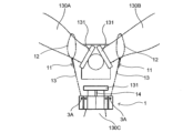
図1(A)、(B)に示すように、風車100は、タワー110と、ナセル120と、3本のブレード130A、130B、130C(以下、3本のブレードを総称してブレード130という場合がある)と、ハブ140とを含む。なお、タワー110は、例えば100m前後の塔状の構造物である。
[1. Configuration of the wind turbine 100]
1A and 1B, the wind turbine 100 includes a tower 110, a nacelle 120, three blades 130A, 130B, and 130C (hereinafter, the three blades may be collectively referred to as blades 130), and a hub 140. The tower 110 is, for example, a tower-like structure of about 100 m.

タワー110は、高さ方向に分割された3つのタワー部材111A、111B、111Cにより構成される(以下、3つのタワー部材を総称してタワー部材111という場合がある)。なお、タワー部材111Aが最上段のタワー部材であり、タワー部材111Bが上から2段目(中段)のタワー部材であり、タワー部材111Cが上から3段目(最下段)のタワー部材である。 The tower 110 is composed of three tower members 111A, 111B, and 111C that are divided in the height direction (hereinafter, the three tower members may be collectively referred to as tower members 111). Note that tower member 111A is the top tower member, tower member 111B is the second tower member from the top (middle), and tower member 111C is the third tower member from the top (bottom).

ナセル120は、軸受けや発電装置等を格納する。発電装置は、ブレード130の回転数を引き上げる増速機や、発電機(誘導発電機、同期発電機等)や、風車100の運転状況等を監視する監視装置を含む。ナセル120は、最上段のタワー部材111Aの上部に取り付けられる。また、ナセル120の正面側にはハブ140が設けられており、ハブ140には3本のブレード130が取り付けられている。 The nacelle 120 houses bearings, a power generating device, etc. The power generating device includes a gearbox that increases the rotation speed of the blades 130, a generator (induction generator, synchronous generator, etc.), and a monitoring device that monitors the operating status of the wind turbine 100. The nacelle 120 is attached to the top of the uppermost tower member 111A. A hub 140 is provided on the front side of the nacelle 120, and three blades 130 are attached to the hub 140.

次に、図2を用いて、ブレード130Cをハブ140から取り外して吊り下ろす際に用いられる吊治具1について説明する。 Next, using Figure 2, we will explain the lifting jig 1 used when removing the blade 130C from the hub 140 and hanging it down.

[2.吊治具1の構成]
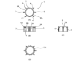
図2(A)~(C)に示すように、吊治具1は、リング状の吊治具本体2と、吊板3と、吊ピース4とを含む。吊治具本体2は2つの半リング状の本体部材2A、2Bからなる。吊治具本体2は、ブレード130Cのフランジ131に下方から当接する。
[2. Configuration of the hanging jig 1]
2A to 2C, the hoisting jig 1 includes a ring-shaped hoisting jig body 2, a hanging plate 3, and a hanging piece 4. The hoisting jig body 2 is made up of two semi-ring-shaped body members 2A and 2B. The hoisting jig body 2 abuts against a flange 131 of the blade 130C from below.

本体部材2A、2Bにはそれぞれ1枚ずつ吊板3が設けられており、吊板3には挿通孔3Aが形成されている。挿通孔3Aには、後述するチェーンブロック11の吊ワイヤー13が取り付けられる。 A hanging plate 3 is provided on each of the main body members 2A and 2B, and an insertion hole 3A is formed in the hanging plate 3. The hanging wire 13 of the chain block 11, which will be described later, is attached to the insertion hole 3A.

また、本体部材2A、2Bにはそれぞれ2枚ずつ吊ピース4が設けられており、吊ピース4には挿通孔4Aが形成されている。挿通孔4Aには、後述するチルクライマー21の吊ワイヤー23が取り付けられる。 In addition, two hanging pieces 4 are provided on each of the main body members 2A and 2B, and the hanging pieces 4 have insertion holes 4A. The hanging wires 23 of the climbers 21, which will be described later, are attached to the insertion holes 4A.

図2(D)に示すように、吊治具1はリング状の吊治具本体2の内側にブレード130を抱え込んだ際に、吊治具本体2の外周がブレード130のフランジ131の外周よりも小さくなっている。 As shown in FIG. 2(D), when the hoisting jig 1 holds the blade 130 inside the ring-shaped hoisting jig body 2, the outer periphery of the hoisting jig body 2 is smaller than the outer periphery of the flange 131 of the blade 130.

[3.風車100の解体方法]
図1~図14を用いて、本実施形態に係る風車100の解体方法について説明する。
[3. Method for dismantling the wind turbine 100]
A method for dismantling a wind turbine 100 according to this embodiment will be described with reference to Figs. 1 to 14.

[3.1.解体工程1]
図1に示すように、まず、ハブ140及びブレード130を回転させて、吊り下ろし対象であるブレード130Cの先端を下方(鉛直方向下向き)に向ける。
[3.1. Demolition process 1]
As shown in FIG. 1, first, the hub 140 and the blade 130 are rotated so that the tip of the blade 130C to be suspended faces downward (vertically downward).

[3.2.解体工程2]
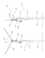
次に、図3に示すように、吊り下ろし対象であるブレード130C以外のブレード130A、130Bにチェーンブロック11を取り付け、チェーンブロック11と吊り下ろし対象であるブレード130Cを接続する。
[3.2. Demolition process 2]
Next, as shown in FIG. 3, the chain block 11 is attached to the blades 130A and 130B other than the blade 130C that is the target to be lowered, and the chain block 11 is connected to the blade 130C that is the target to be lowered.

解体工程2では、吊り下ろし対象であるブレード130Cのフランジ131を下方から支持する吊治具1に対してチェーンブロック11を取り付けることにより、チェーンブロック11と吊り下ろし対象であるブレード130Cを間接的に接続する。 In dismantling process 2, the chain block 11 is attached to the lifting jig 1 that supports from below the flange 131 of the blade 130C to be lowered, thereby indirectly connecting the chain block 11 to the blade 130C to be lowered.

具体的には、2つのチェーンブロック11をそれぞれブレード130Aとブレード130Bに取り付けるために、チェーンブロック11に設けられたチェーンブロック取付ワイヤー12をそれぞれブレード130Aとブレード130Bに括り付ける。また、ブレード130Cにおける、ブレード130Cをハブ140に取り付けるためのフランジ131の下面(ブレード130Cの先端を下方に向けた状態の下側の面)に接するように治具受け具14を取り付ける。次いで予め分割しておいた本体部材2A、2Bをブレード130Cの根元を挟み込み、吊治具本体2の上面が治具受け具14の下面と接するようにボルト接合により取り付ける。 Specifically, to attach the two chain blocks 11 to the blades 130A and 130B, respectively, the chain block attachment wires 12 provided on the chain block 11 are tied to the blades 130A and 130B. In addition, the jig receiver 14 is attached to the blade 130C so that it contacts the underside of the flange 131 (the underside when the tip of the blade 130C faces downward) for attaching the blade 130C to the hub 140. Next, the body members 2A and 2B, which have been separated in advance, are sandwiched around the base of the blade 130C, and the upper surface of the hanging jig body 2 is attached by bolting so that it contacts the underside of the jig receiver 14.

そして、吊治具1の吊板3に形成された挿通孔3Aにチェーンブロック11の吊ワイヤー13を通して固定する。次いで、チェーンブロック11で吊治具1を吊り上げることにより治具受け具14と吊治具1が当接した状態となる。これにより、チェーンブロック11とブレード130Cが間接的に接続され、チェーンブロック11でブレード130Cの荷重を支える。 Then, the hanging wire 13 of the chain block 11 is passed through the insertion hole 3A formed in the hanging plate 3 of the hanging jig 1 and fixed. Next, the hanging jig 1 is lifted by the chain block 11, so that the jig receiver 14 and the hanging jig 1 come into contact with each other. This indirectly connects the chain block 11 and the blade 130C, and the chain block 11 supports the load of the blade 130C.

なお、解体工程2から解体工程5の作業等は、タワー110に沿って設けられたゴンドラ用ワイヤー202により昇降するゴンドラ201に作業員が搭乗して行う。 The work from dismantling process 2 to dismantling process 5 is carried out by workers aboard a gondola 201 that rises and falls on a gondola wire 202 installed along the tower 110.

[3.3.解体工程3]
次に、チェーンブロック11と吊り下ろし対象であるブレード130Cが接続された状態において、ハブ140から吊り下ろし対象であるブレード130Cを取り外す。このとき、チェーンブロック11がブレード130Cの荷重を受けることでブレード130Cの落下を防ぐ。
[3.3. Demolition process 3]
Next, in a state where the blade 130C to be lowered is connected to the chain block 11, the blade 130C to be lowered is removed from the hub 140. At this time, the chain block 11 receives the load of the blade 130C, so that the blade Prevents 130C from falling.

[3.4.解体工程4]
次に、チェーンブロック11と吊り下ろし対象であるブレード130Cが接続された状態において、ハブ140又はナセル120の内部にチルクライマー21を設置し、チルクライマー21と吊り下ろし対象であるブレード130Cを接続する。
[3.4. Demolition process 4]
Next, in a state in which the chain block 11 and the blade 130C to be lowered are connected, the climber 21 is installed inside the hub 140 or the nacelle 120, and the climber 21 and the blade 130C to be lowered are connected. .

解体工程4では、吊治具1に対してチルクライマー21を取り付けることにより、チルクライマー21と吊り下ろし対象であるブレード130Cを間接的に接続する。 In dismantling process 4, the climber 21 is attached to the hoisting jig 1, indirectly connecting the climber 21 to the blade 130C to be lowered.

具体的には、図5に示すように、4つのチルクライマー21(図5は水平方向からの図のため2つのチルクライマー21を示している)をそれぞれハブ140又はナセル120の内部の固定部(図示しない)に取り付けるために、チルクライマー21に設けられたチルクライマー取付ワイヤー22をそれぞれ当該固定部に固定する。 Specifically, as shown in FIG. 5, in order to attach each of the four climbers 21 (FIG. 5 shows two climbers 21 because it is a horizontal view), to a fixed part (not shown) inside the hub 140 or the nacelle 120, the climber attachment wires 22 provided on the climbers 21 are fixed to the fixed part.

そして、吊治具1の吊ピース4に形成された挿通孔4Aにチルクライマー21の吊ワイヤー23を通して固定する。これにより、チルクライマー21とブレード130Cが間接的に接続され、チェーンブロック11とチルクライマー21でブレード130Cの荷重を支える。 Then, the hanging wire 23 of the climber 21 is passed through the insertion hole 4A formed in the hanging piece 4 of the hanging jig 1 and fixed in place. This indirectly connects the climber 21 and the blade 130C, and the chain block 11 and the climber 21 support the load of the blade 130C.

[3.5.解体工程5]
次に、チェーンブロック11と吊り下ろし対象であるブレード130Cの接続を解除する。具体的には、図5に示すように、吊治具1の吊板3の挿通孔3Aに挿通されているチェーンブロック11の吊ワイヤー13を取り外す。これにより、チルクライマー21のみでブレード130Cの荷重を支える。
[3.5. Demolition process 5]
Next, the connection between the chain block 11 and the blade 130C to be lowered is released. Specifically, as shown in FIG. 5, the chain inserted into the insertion hole 3A of the hanging plate 3 of the hanging jig 1 is released. The suspension wire 13 of the block 11 is removed. This allows the load of the blade 130C to be supported only by the climber 21.

[3.6.解体工程6]
次に、図4に示すように、チルクライマー21により吊り下ろし対象であるブレード130Cを地上に吊り下ろす。
[3.6. Demolition process 6]
Next, as shown in FIG. 4, the blade 130C to be lowered is lowered to the ground by the chill climber 21.

なお、解体工程6では、チルクライマー21によりブレード130Cを地上まで吊り下ろすのではなく、図6(A)、図6(B)に示すように、下降の途中でチルクライマー21からクレーン30に吊り替えを行い、クレーン30で地上まで吊り下ろすこととしてもよい。このとき、クレーン30のブーム30Aの先端のフックに取り付けられた吊ワイヤー31は、空いている吊板3の挿通孔3Aに通して固定する。そして、クレーン30のブーム30Aで荷重を受けられるようになったら、チルクライマー21の吊ワイヤー23を吊ピース4の挿通孔4Aから取り外して荷重をチルクライマー21からクレーン30へと切り替える。 In the dismantling process 6, instead of suspending the blade 130C to the ground by the chill climber 21, as shown in Figures 6(A) and 6(B), the blade 130C may be transferred from the chill climber 21 to the crane 30 midway down and then suspended to the ground by the crane 30. At this time, the suspension wire 31 attached to the hook at the tip of the boom 30A of the crane 30 is passed through the free insertion hole 3A of the suspension plate 3 and fixed in place. Then, when the boom 30A of the crane 30 is able to support the load, the suspension wire 23 of the chill climber 21 is removed from the insertion hole 4A of the suspension piece 4, and the load is switched from the chill climber 21 to the crane 30.

解体工程1~解体工程6を各ブレード130について行うことにより、全てのブレード130を取り外す。但し、解体工程2において、取り外したブレード130にはチェーンブロック11を取り付けることができないので、取り外したブレード130が取り付けてあったフランジ穴にアイボルト等の治具を取り付けて、チェーンブロック11を取り付けることとする。 Dismantling steps 1 to 6 are performed on each blade 130 to remove all of the blades 130. However, since the chain block 11 cannot be attached to the removed blades 130 in dismantling step 2, the chain block 11 is attached by attaching a jig such as an eye bolt to the flange hole where the removed blade 130 was attached.

[3.7.解体工程7]
次に、図7-図9に示すような風車施工用架台300を、例えば、クレーン30のメインブームのみで構築する。風車施工用架台300は、風車100のタワー110を囲う位置に構築される内側架台301と、タワー110を囲う位置であって内側架台301の外側に構築される外側架台302と、を含む。また、外側架台302には内側架台用ジャッキ303が4台設けられ、内側架台用ジャッキ303が内側架台301を昇降させる。これにより、外側架台302に対して内側架台301がせり上がり、風車施工用架台300を高くすることができる。
[3.7. Demolition process 7]
Next, a wind turbine construction stand 300 as shown in Fig. 7 to Fig. 9 is constructed, for example, using only the main boom of the crane 30. The wind turbine construction stand 300 is constructed in a position surrounding the tower 110 of the wind turbine 100. The tower 110 includes an inner frame 301 and an outer frame 302 that is constructed outside the inner frame 301 at a position surrounding the tower 110. The outer frame 302 is provided with four inner frame jacks 303. The jack 303 raises and lowers the inner frame 301. As a result, the inner frame 301 rises up relative to the outer frame 302, and the wind turbine construction frame 300 can be made higher.

外側架台302は、架台用マット304の上に配された架台用ガーダー305上に構築される。架台用マット304を設けることにより、風車施工用架台300の自重及び風車100の部材の荷重を広く地面に分散し、地耐力が弱い場所でも施工が可能となる。また、架台用ガーダー305を設けることにより、風車施工用架台300の転倒リスクを低減させる。 The outer frame 302 is constructed on a frame girder 305 arranged on a frame mat 304. By providing the frame mat 304, the weight of the wind turbine construction frame 300 and the load of the components of the wind turbine 100 are widely distributed over the ground, making construction possible even in places with weak bearing capacity. In addition, by providing the frame girder 305, the risk of the wind turbine construction frame 300 toppling over is reduced.

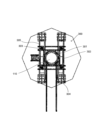
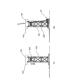
内側架台301には、8台のジャッキを備えるジャッキベース306が固定されている。図10(A)、(B)に示すように、ジャッキベース306は、下段フレーム307、中段支持材308、上段支持材309を備える。下段フレーム307は、内側架台301と同サイズの平面視正方形をしており、4つの角部307Aが内側架台301の柱に固定される。下段フレーム307上には、下段フレーム307の2辺に架かるように4つの中段支持材308が固定されている。また、中段支持材308上には、4つの上段支持材309が固定されている。4つの中段支持材308にはそれぞれ下ジャッキ311が固定されている。同様に4つの上段支持材309にはそれぞれ上ジャッキ310が固定されている。これによりジャッキベース306には、平面視した場合に重ならない位置に4台の上ジャッキ310と4台の下ジャッキ311が固定される。 A jack base 306 equipped with eight jacks is fixed to the inner frame 301. As shown in Figs. 10(A) and (B), the jack base 306 includes a lower frame 307, a middle support member 308, and an upper support member 309. The lower frame 307 is a square in plan view of the same size as the inner frame 301, and four corners 307A are fixed to the columns of the inner frame 301. Four middle support members 308 are fixed to the lower frame 307 so as to span two sides of the lower frame 307. Four upper support members 309 are fixed to the middle support members 308. Lower jacks 311 are fixed to the four middle support members 308, respectively. Similarly, upper jacks 310 are fixed to the four upper support members 309, respectively. This allows four upper jacks 310 and four lower jacks 311 to be fixed to the jack base 306 in positions that do not overlap when viewed in a plan view.

なお、風車施工用架台300は、内側架台301を一番下まで下降させた際に、クレーン30のメインブームのみ(ジブ不要)で組立・解体が可能な高さとする。これによりジブの組立・解体に掛かる時間及びコストを削減でき、クレーンのエリア移動時間も短縮できる。また、風車施工用架台300は、軽量の仮設鋼材を採用することにより、搬出入に大型トレーラーを用いたり、組立・解体に大型クレーンを用いたりする必要が無い。 When the inner frame 301 is lowered to its lowest position, the wind turbine construction frame 300 is set to a height that allows it to be assembled and disassembled using only the main boom of the crane 30 (no jib required). This reduces the time and cost required to assemble and disassemble the jib, and also reduces the time it takes for the crane to move between areas. In addition, by using lightweight temporary steel materials, the wind turbine construction frame 300 does not require the use of large trailers for transporting it in and out, or large cranes for assembly and disassembly.

[3.8.解体工程8]
次に、解体工程7で構築した風車施工用架台300の内側架台301を4台の内側架台用ジャッキ303により水平に上昇させ(せり上げ)、その状態で内側架台301と外側架台302を鋼材(図示しない)で接続する。これにより、風車施工用架台300の安定性を向上させ、強風等により転倒することを防止する。なお、内側架台301に作業用足場を設けておくことにより、高所で安全に作業を行うことができる。
[3.8. Demolition process 8]
Next, the inner frame 301 of the wind turbine construction frame 300 constructed in the dismantling process 7 is raised horizontally (lifted up) by four inner frame jacks 303, and in this state, the inner frame 301 and the outer frame 302 are attached to the steel material ( This improves the stability of the wind turbine construction frame 300 and prevents it from falling over due to strong winds, etc. By providing a work platform on the inner frame 301, it is possible to You can work safely.

[3.9.解体工程9]
次に、タワー部材111Bとタワー部材111Cに吊点を設ける。具体的には図11(A)~(E)に示すように、タワー部材111Bの下部とタワー部材111Cの上部(すなわち、タワー部材111Bとタワー部材111Cの接合部近傍)に、それぞれ吊具313が設けられた二本の鋼材312を上下で直角に交差するように貫通させる。これにより、タワー部材111Bとタワー部材111Cのそれぞれに4つの吊点が設けられる。
[3.9. Demolition process 9]
Next, a suspension point is provided to the tower member 111B and the tower member 111C. Specifically, as shown in FIG. 11(A) to (E), a suspension point is provided to the lower part of the tower member 111B and the upper part of the tower member 111C (i.e., the tower member Two steel members 312 each having a hoist 313 are inserted between the tower members 111B and 111C (near the joint between the tower members 111B and 111C) so as to cross at right angles. Four suspension points are provided.

[3.10.解体工程10]
次に、タワー部材111C(「最下段にあるタワー部材」の一例)とタワー部材111B(「最下段から一段上にあるタワー部材」の一例)を分割する(「分割工程」の一例)。なお、解体工程10は、タワー部材111Bと4台の上ジャッキ310の接続(後続の解体工程11を参照)、及び、タワー部材111Cと4台の下ジャッキ311の接続(後続の解体工程12を参照)の少なくとも一方が完了してから行うこととしてもよい。これにより、タワー部材111B、タワー部材111Cの少なくとも一方がジャッキにより支持された状態で分割できるため安定して作業を行うことができる。
[3.10. Demolition process 10]
Next, the tower member 111C (an example of the "lowest tower member") and the tower member 111B (an example of the "next tower member above the lowest") are separated (an example of the "separation step"). Dismantling step 10 includes connecting the tower member 111B to the four upper jacks 310 (see the following dismantling step 11), and connecting the tower member 111C to the four lower jacks 311 (see the following dismantling step 12). In this way, at least one of the tower members 111B and 111C can be separated while being supported by the jack, so that the work can be performed stably.

[3.11.解体工程11]
次に、4台の上ジャッキ310の吊ワイヤー314に設けられたアンカーをそれぞれタワー部材111Bに設けた4つの吊具(吊点)313に接続し、吊り上げる(「支持工程」の一例)。これにより、タワー部材111Bより上方の風車100の部材(タワー部材111B、タワー部材111A、ナセル120、ハブ140)の荷重を4台の上ジャッキ310により水平に支持する。また、4台の上ジャッキ310により4点で吊り上げることにより風の影響を受けにくく、例えば1台のクレーンにより1点で吊り上げる場合よりも荷振れや荷の回転を抑制できる。
[3.11. Demolition process 11]
Next, the anchors provided on the hoisting wires 314 of the four upper jacks 310 are connected to the four hoisting devices (suspension points) 313 provided on the tower member 111B, respectively, and the tower member 111B is hoisted up (an example of the "supporting step"). Thus, the load of the members of the wind turbine 100 above the tower member 111B (the tower member 111B, the tower member 111A, the nacelle 120, and the hub 140) is horizontally supported by the four upper jacks 310. By hoisting the load at four points, it is less susceptible to the effects of wind, and the load swaying and rotation can be reduced more than when hoisting the load at one point using a single crane, for example.

[3.12.解体工程12]
次に、4台の下ジャッキ311の吊ワイヤー314に設けられたアンカーをそれぞれタワー部材111Cに設けた吊具(吊点)313に接続し、吊り上げる。これにより、タワー部材111Cを地面から水平に浮かすことができる。また、上ジャッキ310と同様に、4台の下ジャッキ311により4点で吊り上げることにより風の影響を受けにくく、例えば1台のクレーンにより1点で吊り上げる場合よりも荷振れや荷の回転を抑制できる。
[3.12. Demolition process 12]
Next, the anchors provided on the hoisting wires 314 of the four lower jacks 311 are connected to the hoisting devices (suspension points) 313 provided on the tower member 111C, respectively, and the tower member 111C is lifted up. As a result, the tower member 111C is horizontally lifted from the ground. In addition, by lifting the load at four points using the four lower jacks 311 in the same manner as the upper jacks 310, the load is less susceptible to the effects of wind, and is less susceptible to load swinging and other problems than when lifting the load at one point using a single crane. Rotation of the load can be suppressed.

[3.13.解体工程13]
次に、工解体程12で浮かしたタワー部材111Cと地面の間に台車315を入れ、次いで、タワー部材111Cを4台の下ジャッキ311により水平に下降させて台車315に載せる。
[3.13. Demolition process 13]
Next, a dolly 315 is inserted between the tower member 111C that has been lifted in the dismantling step 12 and the ground, and then the tower member 111C is lowered horizontally by the four lower jacks 311 and placed on the dolly 315.

[3.14.解体工程14]
次に、図12(A)に示すように、4台の下ジャッキ311によりタワー部材111Cを下降させつつ、台車315をウインチ(図示しない)で横引きすることにより、タワー部材111Cを横倒しにする。
[3.14. Demolition process 14]
Next, as shown in FIG. 12A, the tower member 111C is lowered by the four lower jacks 311 while the dolly 315 is pulled sideways by a winch (not shown) to lay the tower member 111C sideways. .

[3.15.解体工程15]
次に、4台の下ジャッキ311とクレーン30でタワー部材111Cを相吊りして、風車施工用架台300から搬出しつつトレーラー(図示しない)に載せる。なお、解体工程14~解体工程15は「搬出工程」の一例である。
[3.15. Demolition process 15]
Next, the tower member 111C is hoisted by the four lower jacks 311 and the crane 30, and is removed from the wind turbine construction stand 300 and placed on a trailer (not shown). This is an example of a "carry-out process."

[3.16.解体工程16]
次に、4台の下ジャッキ311の吊ワイヤー314とタワー部材111Cを切り離す。
[3.16. Demolition process 16]
Next, the suspension wires 314 of the four lower jacks 311 are disconnected from the tower member 111C.

[3.17.解体工程17]
次に、4台の上ジャッキ310によりタワー部材111Bより上方の風車100の部材(タワー部材111B、タワー部材111A、ナセル120、ハブ140)を地面まで下降させる(「風車部材下降工程」の一例)。これにより、タワー部材111Bが最下段にあるタワー部材となる。
[3.17. Demolition process 17]
Next, the four upper jacks 310 are used to lower the components of the wind turbine 100 above the tower member 111B (the tower member 111B, the tower member 111A, the nacelle 120, and the hub 140) to the ground (an example of a "wind turbine component lowering process"). This makes tower member 111B the lowest tower member.

[3.18.解体工程18]
次に、図12(B)に示すように、タワー部材111B、タワー部材111Aについてもタワー部材111Cと同様に解体工程9~解体工程17を繰り返し、風車施工用架台300から搬出する。なお、解体工程9では上ジャッキ310と下ジャッキ311で吊り替えを行う。具体的には、最下段にある(最下段の位置にある。以下同様)タワー部材111の上部と、その一段上にあるタワー部材111の下部に鋼材を貫通させて吊点を設け、それぞれ、下ジャッキ311と上ジャッキ310を吊ワイヤー314で接続する。但し、最上段のタワー部材111Aについては、上ジャッキ310から下ジャッキ311に吊り替えを行わなくても風車施工用架台300から搬出可能であれば、そのまま上ジャッキ310で下部を吊ったまま搬出することとしてもよい。
[3.18. Demolition process 18]
Next, as shown in FIG. 12B, the dismantling steps 9 to 17 are repeated for the tower members 111B and 111A in the same manner as for the tower member 111C, and the tower members 111B and 111A are removed from the wind turbine construction frame 300. In step 9, the upper jack 310 and the lower jack 311 are used to switch the suspension. Specifically, the upper part of the tower member 111 at the lowest level (located at the lowest level; the same applies below) and the tower member 112 at the level above it are used to switch the suspension. A steel material is passed through the lower part of the tower member 111 to provide a suspension point, and the lower jack 311 and the upper jack 310 are connected to each other by a suspension wire 314. However, for the top tower member 111A, the upper jack 310 is connected to the lower jack 311 by a suspension wire 314. If it is possible to remove the wind turbine construction stand 300 without changing the suspension, it may be removed while the lower part is still suspended by the upper jack 310.

[3.19.解体工程19]
タワー部材111B又はタワー部材111Aについての解体工程17において、ナセル120が内側架台301の上部に予め設けられたナセル載置部(「載置部」の一例)まで下降してきて、ナセル120がナセル載置部に載置されたら下降を停止する。そして、ナセル120を内側架台301に固定してから、ナセル120とタワー部材111Aを切り離す(「切り離し工程」の一例)。
[3.19. Demolition process 19]
In the dismantling process 17 for the tower member 111B or the tower member 111A, the nacelle 120 is lowered to a nacelle mounting portion (an example of a "mounting portion") provided in advance on the upper portion of the inner frame 301, and the nacelle 120 is placed on the nacelle mounting portion. The descent is stopped when the nacelle 120 is placed on the placement portion. Then, the nacelle 120 is fixed to the inner frame 301, and then the nacelle 120 and the tower member 111A are separated (an example of a "separation process").

[3.20.解体工程20]
次に、解体工程19により、ナセル120とタワー部材111Aを切り離したら、図12(C)に示すように、タワー部材111Aについて解体工程13~解体工程16を行う。
[3.20. Demolition process 20]
Next, after the nacelle 120 and the tower member 111A are separated in dismantling step 19, dismantling steps 13 to 16 are carried out on the tower member 111A as shown in FIG. 12(C).

[3.21.解体工程21]
そして、全てのタワー部材111の搬出が完了したら、次いで、図13(A)に示すように、ナセル120が載置・固定された内側架台301を内側架台用ジャッキ303により下降させる(「架台下降工程」の一例)。
[3.21. Demolition process 21]
Then, when all the tower members 111 have been completely removed, the inner frame 301 on which the nacelle 120 is placed and fixed is lowered by the inner frame jack 303 as shown in FIG. 13A ("frame lowering"). (An example of a "process").

[3.22.解体工程22]
次に、図13(B)に示すように、ナセル120を内側架台301に載置された状態で、クレーン30を用いて解体する。風車100の構成部品の中で最も重量のあるナセル120を内側架台301に載せて内側架台301を下降させることで解体の際の揚程が低くなり、また、解体に要するクレーンも小型のものを利用することができる。
[3.22. Demolition process 22]
Next, as shown in FIG. 13B, the nacelle 120 is dismantled using the crane 30 while it is placed on the inner frame 301. The nacelle 120, which is the heaviest component of the wind turbine 100, is By placing the structure on the inner frame 301 and lowering the inner frame 301, the lifting height required for dismantling is reduced, and a small crane can be used for dismantling.

[3.23.解体工程23]
次に、クレーン30を用いて風車施工用架台300を解体する。
[3.23. Demolition process 23]
Next, the wind turbine construction frame 300 is dismantled using the crane 30.

このように、本実施形態の風車100の解体方法では、だるま落としの要領で、最下段の位置にあるタワー部材111の分割、搬出を繰り返すことでタワー110を解体していく。なお、本実施形態では、タワー110が3段のタワー部材111で構成されている場合について説明したが、4段以上のタワー部材111で構成されるタワー110についても本解体方法を適用することができる。 In this manner, in the method for dismantling the wind turbine 100 of this embodiment, the tower 110 is dismantled by repeatedly dividing and removing the tower member 111 in the lowest position in a manner similar to that of a Daruma-otoshi game. Note that, although this embodiment has been described as being composed of three tiers of tower members 111, this dismantling method can also be applied to towers 110 composed of four or more tiers of tower members 111.

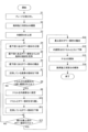
ここで、図14のフローチャートを用いて風車100の解体方法の流れの一例について説明する。 Here, an example of the flow of a method for dismantling the wind turbine 100 will be explained using the flowchart in Figure 14.

まず、ブレード130をハブ140から取り外す(ステップS1)。ステップS1は、上述した解体工程1~解体工程6に対応する。 First, the blade 130 is removed from the hub 140 (step S1). Step S1 corresponds to disassembly steps 1 to 6 described above.

次に、風車施工用架台300を構築する(ステップS2)。ステップS2は、上述した解体工程7に対応する。 Next, the wind turbine construction stand 300 is constructed (step S2). Step S2 corresponds to the dismantling step 7 described above.

次に、内側架台301を上昇させる(ステップS3)。ステップS3は、上述した解体工程8に対応する。 Next, the inner frame 301 is raised (step S3). Step S3 corresponds to dismantling step 8 described above.

次に、最下段にあるタワー部材111と、その一段上にあるタワー部材111を分割する(ステップS4)。ステップS4は、上述した解体工程10に対応する。 Next, the tower member 111 at the bottom level is separated from the tower member 111 at the level above (step S4). Step S4 corresponds to the dismantling process 10 described above.

次に、最下段にあるタワー部材111より上の風車100の部材を上ジャッキ310により支持する(ステップS5)。なお、ステップS5の前までに(好ましくはステップS4の前までに)、最下段にあるタワー部材111と、その一段上にあるタワー部材111に吊点を設け(上述した解体工程9に対応)、最下段にあるタワー部材111と下ジャッキ311を接続し、その一段上にあるタワー部材111と上ジャッキ310を接続しておくこととする。ステップS5は、上述した解体工程11に対応する。 Next, the components of the wind turbine 100 above the lowest tower member 111 are supported by the upper jack 310 (step S5). Note that before step S5 (preferably before step S4), suspension points are provided on the lowest tower member 111 and the tower member 111 one level above (corresponding to dismantling step 9 described above), the lowest tower member 111 is connected to the lower jack 311, and the tower member 111 one level above is connected to the upper jack 310. Step S5 corresponds to dismantling step 11 described above.

次に、最下段にあるタワー部材111を、下ジャッキ311を用いて風車施工用架台300から搬出する(ステップS6)。ステップS6は、上述した解体工程12~解体工程15に対応する。 Next, the lowest tower member 111 is removed from the wind turbine construction stand 300 using the lower jack 311 (step S6). Step S6 corresponds to the above-mentioned dismantling steps 12 to 15.

次に、上ジャッキ310により支持している風車100の部材を下降させる(ステップS7)。ステップS7は、上述した解体工程17に対応する。 Next, the components of the wind turbine 100 supported by the upper jack 310 are lowered (step S7). Step S7 corresponds to the dismantling process 17 described above.

ステップS7の途中で、ナセル120が内側架台301の上部のナセル載置部に載置された場合には(ステップS8:YES)、ナセル120を内側架台301に固定し(ステップS9)、ナセル120とタワー部材111Aを切り離してから(ステップS10)、再度、上ジャッキ310により支持しているタワー部材111を下降させる(ステップS11)。ステップS9、ステップS10は、上述した解体工程19に対応し、ステップS11は、上述した解体工程17に対応する。 If the nacelle 120 is placed on the nacelle placement section on the upper part of the inner frame 301 during step S7 (step S8: YES), the nacelle 120 is fixed to the inner frame 301 (step S9), the nacelle 120 is separated from the tower member 111A (step S10), and the tower member 111 supported by the upper jack 310 is lowered again (step S11). Steps S9 and S10 correspond to the dismantling process 19 described above, and step S11 corresponds to the dismantling process 17 described above.

一方、ナセル120が内側架台301の上部のナセル載置部に載置されない場合には(ステップS8:NO)、ステップS12に移行する。 On the other hand, if the nacelle 120 is not placed on the nacelle mounting portion at the top of the inner frame 301 (step S8: NO), proceed to step S12.

次に、搬出が済んでいない残りのタワー部材111が最上段のタワー部材111Aだけではない場合には(ステップS12:NO)、ステップS4に移行する。一方、搬出が済んでいない残りのタワー部材111が最上段のタワー部材111Aだけである場合には(ステップS12:YES)、次いで、最上段のタワー部材111Aを風車施工用架台300から搬出する(ステップS13)。ステップS13は、上述した解体工程18で繰り返す解体工程9~解体工程16に対応する。 Next, if the topmost tower member 111A is not the only remaining tower member 111 that has not been removed (step S12: NO), proceed to step S4. On the other hand, if the topmost tower member 111A is the only remaining tower member 111 that has not been removed (step S12: YES), then the topmost tower member 111A is removed from the wind turbine construction stand 300 (step S13). Step S13 corresponds to dismantling steps 9 to 16 that are repeated in the dismantling step 18 described above.

次に、内側架台301をナセル120とともに下降させる(ステップS14)。ステップS14は、上述した解体工程21に対応する。 Next, the inner frame 301 is lowered together with the nacelle 120 (step S14). Step S14 corresponds to the dismantling process 21 described above.

次に、クレーン30を用いてナセル120を内側架台301上で解体する(ステップS15)。ステップS15は、上述した解体工程22に対応する。 Next, the nacelle 120 is dismantled on the inner frame 301 using the crane 30 (step S15). Step S15 corresponds to the dismantling process 22 described above.

次に、クレーン30を用いて風車施工用架台300を解体する(ステップS16)。ステップS16は、上述した解体工程23に対応する。 Next, the wind turbine construction stand 300 is dismantled using the crane 30 (step S16). Step S16 corresponds to the dismantling process 23 described above.

以上説明したように、本実施形態の風車100の解体方法は、
風車100のタワー110を囲う位置に構築される内側架台301(「第1架台」の一例)と、タワー110を囲う位置であって内側架台301の外側に構築される外側架台302(「第2架台」の一例)と、外側架台302に設けられ、内側架台301を昇降させる内側架台用ジャッキ303(「架台用昇降手段」の一例)と、内側架台301に設けられ、タワー110を構成する複数のタワー部材111のうち最下段にあるタワー部材111より上にあるその他のタワー部材111を吊った状態で昇降させる上ジャッキ310(「第1昇降手段」の一例)と、内側架台301に設けられ、最下段にあるタワー部材111を吊った状態で昇降させる下ジャッキ311(「第2昇降手段」の一例)と、を備える風車施工用架台300を用いた風車100の解体方法であって、最下段にあるタワー部材111と、最下段から一段上にあるタワー部材111を分割する解体工程10(「分割工程」の一例)と、内側架台301が外側架台302に対してせり上がった状態で、上ジャッキ310により最下段にあるタワー部材111より上にある風車100の部材の荷重を支持する解体工程11(「支持工程」の一例)と、上ジャッキ310により荷重を支持している状態で、下ジャッキ311により最下段にあるタワー部材111を支持しつつ、風車施工用架台300から搬出する解体工程14及び解体工程15(「搬出工程」の一例)と、を含む。
As described above, the method for dismantling the wind turbine 100 according to the present embodiment includes the following steps:
The wind turbine 100 includes an inner frame 301 (an example of a "first frame") constructed in a position surrounding the tower 110 of the wind turbine 100, an outer frame 302 (an example of a "second frame") constructed in a position surrounding the tower 110 and outside the inner frame 301, an inner frame jack 303 (an example of a "frame lifting means") provided on the outer frame 302 and used to lift and lower the inner frame 301, an upper jack 310 (an example of a "first lifting means") provided on the inner frame 301 and used to lift and lower the other tower members 111 above the lowest tower member 111 among the multiple tower members 111 constituting the tower 110 while suspending them, and a lower jack 311 (an example of a "second frame") provided on the inner frame 301 and used to lift and lower the lowest tower member 111 while suspending them. a "second lifting means" for lifting the inner frame 301 upward from the outer frame 302, and includes a dismantling process 10 (an example of a "dividing process") of separating the lowest tower member 111 and the tower member 111 one step above the lowest member, a dismantling process 11 (an example of a "supporting process") of supporting the load of the members of the wind turbine 100 higher than the lowest tower member 111 by the upper jacks 310 while the inner frame 301 is raised up relative to the outer frame 302, and a dismantling process 14 and a dismantling process 15 (an example of a "transporting process") of transporting the lowest tower member 111 from the wind turbine construction frame 300 while supporting it by the lower jacks 311 while the load is supported by the upper jacks 310.

したがって、本実施形態の風車100の解体方法によれば、風車100のタワー110を囲う位置に構築される内側架台301と外側架台302が二重に構築され、内側架台301が外側架台302からせり上がり、内側架台301に設けられた上ジャッキ310により風車100の最下段にあるタワー部材111より上方の風車100の部材を支持している間に、内側架台301に設けられた下ジャッキ311により最下段にあるタワー部材111を搬出することから、クレーン等を設置するための広大な用地が不要であり、狭い土地においても巨大な風車の解体を行うことができる。 Therefore, according to the method for dismantling the wind turbine 100 of this embodiment, the inner frame 301 and the outer frame 302 are constructed in a double structure in a position surrounding the tower 110 of the wind turbine 100, the inner frame 301 rises up from the outer frame 302, and while the upper jack 310 provided on the inner frame 301 supports the wind turbine 100 components above the tower member 111 at the bottom of the wind turbine 100, the lower jack 311 provided on the inner frame 301 removes the tower member 111 at the bottom, so that a large area for installing a crane or the like is not required, and a huge wind turbine can be dismantled even on a small piece of land.

また、本実施形態の風車100の解体方法は、解体工程14及び解体工程15の後に、上ジャッキ310により搬出したタワー部材111より上のその他のタワー部材111を下降させる解体工程17(「風車部材下降工程」の一例)を更に含む。これにより、先に搬出したタワー部材111より一段上のタワー部材を次の搬出対象となる最下段にあるタワー部材111とすることができる。 The method for dismantling the wind turbine 100 of this embodiment further includes, after dismantling steps 14 and 15, a dismantling step 17 (an example of a "wind turbine member lowering step") in which the upper jack 310 is used to lower the other tower members 111 above the tower member 111 that has been transported out. This allows the tower member one level above the previously transported tower member 111 to become the lowest tower member 111 to be transported next.

さらに、本実施形態の風車100の解体方法は、解体工程10(「分割工程」の一例)、解体工程11(「支持工程」の一例)、解体工程14及び解体工程15(「搬出工程」の一例)、解体工程17(「風車部材下降工程」の一例)を繰り返し、タワー110を構成する全てのタワー部材111を搬出する。これにより、大型のクレーン等を用いずに狭い土地においても全てのタワー部材111を解体・搬出することできる。 Furthermore, the method for dismantling the wind turbine 100 of this embodiment repeats dismantling process 10 (an example of a "division process"), dismantling process 11 (an example of a "support process"), dismantling process 14 and dismantling process 15 (an example of a "transportation process"), and dismantling process 17 (an example of a "wind turbine component lowering process") to transport all of the tower components 111 that make up the tower 110. This makes it possible to dismantle and transport all of the tower components 111 even on a small piece of land without using a large crane, etc.

さらにまた、本実施形態の風車100の解体方法は、内側架台301がその頂部にタワー部材111A(「最上段のタワー部材」の一例)の上部に設置されたナセル120を載置可能な載置部を有し、解体工程17によりナセル120が載置部に載置された場合に、タワー部材111Aとナセル120を切り離す解体工程19(「切り離し工程」の一例)を更に含む。これにより、ナセル120が安定した状態で、ナセル120とタワー部材111Aを切り離すことができる。 Furthermore, the method for dismantling the wind turbine 100 of this embodiment further includes a dismantling process 19 (an example of a "separating process") in which the inner frame 301 has a mounting portion at its top on which the nacelle 120 installed on top of the tower member 111A (an example of a "topmost tower member") can be placed, and in which the tower member 111A and the nacelle 120 are separated when the nacelle 120 is placed on the mounting portion by the dismantling process 17. This allows the nacelle 120 to be separated from the tower member 111A while the nacelle 120 is in a stable state.

さらにまた、本実施形態の風車100の解体方法は、ナセル120が載置部に載置された状態で、内側架台用ジャッキ303がせり上がった状態の内側架台301を下降させる解体工程21(「架台下降工程」の一例)を更に含む。これにより、風車100の構成部品の中でも重量のあるナセル120を安定して下方に移動させて解体することができる。 Furthermore, the method for dismantling the wind turbine 100 of this embodiment further includes a dismantling step 21 (an example of a "mount lowering step") in which the inner mount jack 303 is lowered while the nacelle 120 is placed on the mounting section, thereby allowing the nacelle 120, which is one of the heaviest components of the wind turbine 100, to be stably moved downward and dismantled.

なお、解体工程11では、上ジャッキ310により最下段にあるタワー部材111より上にある風車100の部材の荷重を支持することができればよく、上ジャッキ310は、タワー部材111Bのみならず、タワー部材111Aに吊点を設けて吊り上げることにより、これを支持することとしてもよい。 In addition, in dismantling process 11, it is sufficient that the upper jack 310 is able to support the weight of the components of the wind turbine 100 above the lowest tower member 111, and the upper jack 310 may support not only tower member 111B, but also tower member 111A by providing a suspension point to lift it up.

[4.風車100の組立方法]
次に、風車施工用架台300を用いた風車100の組立方法について説明する。基本的には、上述した風車100の解体方法を逆手順で行うことにより風車100を組み立てることができる。以下、風車100の組立方法について説明する。
4. Method of Assembling the Wind Turbine 100
Next, a method for assembling the wind turbine 100 using the wind turbine construction frame 300 will be described. Basically, the wind turbine 100 can be assembled by performing the above-mentioned method for dismantling the wind turbine 100 in reverse order. The method for assembling the wind turbine 100 will be described below.

[4.1.組立工程1]
まず、風車100の解体方法の解体工程7と同様に、風車施工用架台300を構築する。
[4.1. Assembly process 1]
First, similarly to dismantling step 7 of the method for dismantling the wind turbine 100, the wind turbine construction stand 300 is constructed.

[4.2.組立工程2]
次に、図13(B)に示すように、クレーン30を用いてナセル120を内側架台301上で組み立てる。ナセル120が完成したら、ナセル120を内側架台301に固定する
[4.2. Assembly process 2]
Next, as shown in FIG. 13B, the nacelle 120 is assembled on the inner frame 301 using the crane 30. When the nacelle 120 is completed, the nacelle 120 is fixed to the inner frame 301.

[4.3.組立工程3]
次に、図13(A)に示すように、ナセル120が載置された状態の内側架台301を内側架台用ジャッキ303により水平に上昇させる(「架台上昇工程」の一例)。
[4.3. Assembly process 3]
Next, as shown in FIG. 13A, the inner frame 301 on which the nacelle 120 is placed is raised horizontally by the inner frame jacks 303 (an example of a "frame raising step").

[4.4.組立工程4]
次に、トレーラー(図示しない)によりタワー部材111Aを搬入し、4台の下ジャッキ311をタワー部材111Aの上部と接続する。なお、タワー部材111Aには予め吊点を設けておくこととする(但し、解体方法の場合とは異なり、鋼材を貫通させて吊点を設けるのではなく、タワー部材111の外壁面に吊具を設けるなどするのが強度や外観を考慮すると好ましい)。次いで、タワー部材111Aの下部をトレーラーから台車315に積み替える。
[4.4. Assembly process 4]
Next, the tower member 111A is brought in by a trailer (not shown), and the four lower jacks 311 are connected to the upper part of the tower member 111A. Note that the tower member 111A is provided with a suspension point in advance (however, unlike the dismantling method, it is preferable to provide a suspension tool on the outer wall surface of the tower member 111, rather than providing a suspension point by penetrating a steel material, in consideration of strength and appearance). Next, the lower part of the tower member 111A is transferred from the trailer to the dolly 315.

[4.5.組立工程5]
次に、図12(C)に示すように、タワー部材111Aの上部を4台の下ジャッキ311で吊り上げつつ、タワー部材111Aの下部を台車115でスライドさせ、タワー部材111Aを内側架台301の内部に滑り込ませて、立たせた状態で配置する。
[4.5. Assembly process 5]
Next, as shown in FIG. 12(C), the upper part of the tower member 111A is lifted by four lower jacks 311 while the lower part of the tower member 111A is slid by the dolly 115, so that the tower member 111A is slid inside the inner frame 301 and positioned in an upright position.

[4.6.工程6]
次に、下ジャッキ311でタワー部材111Aの上部を吊った状態で、上ジャッキ310の吊ワイヤー314をタワー部材111Aの下部に予め設けられた吊点(但し、解体方法の場合とは異なり、鋼材を貫通させて吊点を設けるのではなく、タワー部材111の外壁面に吊具を設けるなどするのが強度や外観を考慮すると好ましい)に取り付けることで下ジャッキ311から上ジャッキ310に吊り替えを行う。
[4.6. Step 6]
Next, with the upper part of the tower member 111A suspended by the lower jack 311, the suspension wire 314 of the upper jack 310 is attached to a suspension point previously installed at the lower part of the tower member 111A (however, unlike the dismantling method, in consideration of strength and appearance, it is preferable to install a suspension device on the outer wall surface of the tower member 111 rather than installing a suspension point by penetrating steel material), thereby transferring the suspension from the lower jack 311 to the upper jack 310.

[4.7.組立工程7]
次に、タワー部材111A(「一部のタワー部材」、「最上段のタワー部材」の一例)を4台の上ジャッキ310で水平に吊り上げ(「吊り上げ工程」の一例)、上部がナセル120に接触したところで吊り上げを止める。
[4.7. Assembly process 7]
Next, tower member 111A (an example of "a portion of the tower members" or "the topmost tower member") is lifted horizontally by four upper jacks 310 (an example of the "lifting process"), and the lifting is stopped when the upper part comes into contact with the nacelle 120.

[4.8.組立工程8]
次に、タワー部材111Aの上部とナセル120を接合する。なお、組立工程7及び組立工程8は「ナセル接合工程」の一例である。
[4.8. Assembly process 8]
Next, the upper part of the tower member 111A is joined to the nacelle 120. Note that assembly process 7 and assembly process 8 are examples of a "nacelle joining process".

[4.9.組立工程9]
次に、図12(B)に示すように、タワー部材111Bについて組立工程4、5を行い、タワー部材111Bをタワー部材111Aの下方に配置する(「配置工程」の一例)。
[4.9. Assembly process 9]
Next, as shown in FIG. 12B, assembly steps 4 and 5 are performed on the tower member 111B, and the tower member 111B is disposed below the tower member 111A (an example of an "arrangement step").

[4.10.組立工程10]
次に、上ジャッキ310によりタワー部材111A及びナセル120(「一部のタワー部材」の一例)を水平に下降させ、組立工程9で配置したタワー部材111B(「その他のタワー部材」の一例)の上に載置する(「載置工程」の一例)。
[4.10. Assembly process 10]
Next, tower member 111A and nacelle 120 (an example of "some of the tower members") are lowered horizontally by upper jack 310 and placed on top of tower member 111B (an example of "other tower members") arranged in assembly process 9 (an example of a "loading process").

[4.11.組立工程11]
次に、タワー部材111Bの上部とタワー部材111Aの下部を接合する(「タワー部材接合工程」の一例)。
[4.11. Assembly process 11]
Next, the upper part of tower member 111B and the lower part of tower member 111A are joined together (an example of a "tower member joining process").

[4.12.組立工程12]
次に、タワー部材111Bについて組立工程6を行う。
[4.12. Assembly process 12]
Next, assembly process 6 is performed on the tower member 111B.

[4.13.組立工程13]
次に、タワー部材111B及びその上のタワー部材111A(「一部のタワー部材」の一例)を4台の上ジャッキ310で水平に吊り上げ(「吊り上げ工程」の一例)、下方にタワー部材111Cを配置可能なスペースができたところで吊り上げを止める。
Assembly process 13
Next, tower member 111B and the tower member 111A above it (an example of a "part of the tower member") are lifted horizontally by four upper jacks 310 (an example of a "lifting process"), and the lifting is stopped when space is created below in which tower member 111C can be placed.

[4.14.組立工程14]
次に、図12(A)に示すように、タワー部材111Cについて組立工程4、5を行い、タワー部材111Bをタワー部材111Bの下方に配置する(「配置工程」の一例)。
[4.14. Assembly process 14]
Next, as shown in FIG. 12A, assembly steps 4 and 5 are performed on tower member 111C, and tower member 111B is disposed below tower member 111B (an example of an "arrangement step").

[4.15.組立工程15]
次に、上ジャッキ310によりタワー部材111A、タワー部材111B及びナセル120(「一部のタワー部材」の一例)を水平に下降させ、組立工程14で配置されたタワー部材111C(「その他のタワー部材」の一例)の上に載置する(「載置工程」の一例)。
4.15. Assembly process 15
Next, tower member 111A, tower member 111B and nacelle 120 (an example of "some of the tower members") are lowered horizontally by upper jack 310 and placed on top of tower member 111C (an example of "other tower members") that was arranged in assembly process 14 (an example of a "loading process").

[4.16.組立工程16]
次に、タワー部材111Cの上部とタワー部材111Bの下部を接合する(「タワー部材接合工程」の一例)。タワー部材111A、タワー部材111B及びタワー部材111Cを接合してタワー110ができたら、タワー110を上ジャッキ310で吊り上げ(ジャッキアップし)、基礎上に吊り下げて(ジャッキダウンして)基礎に固定する。
Assembly Process 16
Next, the upper part of tower member 111C and the lower part of tower member 111B are joined (an example of a "tower member joining process"). After tower member 111A, tower member 111B, and tower member 111C are joined to complete tower 110, tower 110 is lifted (jacked up) by upper jack 310 and suspended (jacked down) above the foundation to be fixed to the foundation.

[4.17.組立工程17]
次に、内側架台301を下降させた後、風車施工用架台300を解体する。
Assembly process 17
Next, the inner frame 301 is lowered, and then the wind turbine construction frame 300 is dismantled.

[4.18.組立工程18]
次に、クレーン30を用いてハブ140に3本のブレード130を取り付ける。
Assembly Process 18
Next, the three blades 130 are attached to the hub 140 using the crane 30 .

このように、本実施形態の風車100の組立方法では、だるま落としの逆手順の要領で、最下段の位置にタワー部材111を継ぎ足していくことでタワー110を組み立てていく。本実施形態では、タワー110が3段のタワー部材111で構成されている場合について説明したが、4段以上のタワー部材111で構成されるタワー110についても本組立方法を適用することができる。 In this way, in the assembly method for the wind turbine 100 of this embodiment, the tower 110 is assembled by adding tower members 111 to the lowest position in a reverse manner to the Daruma-otoshi game. In this embodiment, the case where the tower 110 is composed of three stages of tower members 111 has been described, but this assembly method can also be applied to a tower 110 composed of four or more stages of tower members 111.

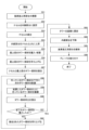
ここで、図15のフローチャートを用いて風車100の組立方法の流れの一例について説明する。 Here, an example of the flow of the assembly method of the wind turbine 100 will be explained using the flowchart in Figure 15.

まず、クレーン30を用いて、タワー110を設置する位置を囲うように、内側架台301及び外側架台302を配置した風車施工用架台300を構築する(ステップS51)。ステップS51は、上述した組立方法の組立工程1に対応する。 First, the crane 30 is used to construct the wind turbine construction frame 300, which includes the inner frame 301 and the outer frame 302, so as to surround the position where the tower 110 is to be installed (step S51). Step S51 corresponds to assembly step 1 of the assembly method described above.

次に、クレーン30を用いて、ナセル120を内側架台301の載置部に固定し(ステップS52)、載置部にてナセル120を組み立てる(ステップS53)。ステップS52、ステップS53は、上述した組立方法の組立工程2に対応する。 Next, the nacelle 120 is fixed to the mounting portion of the inner frame 301 using the crane 30 (step S52), and the nacelle 120 is assembled on the mounting portion (step S53). Steps S52 and S53 correspond to assembly step 2 of the assembly method described above.

次に、内側架台301をナセル120とともに上昇させる(ステップS54)。ステップS54は、上述した組立方法の組立工程3に対応する。 Next, the inner frame 301 is raised together with the nacelle 120 (step S54). Step S54 corresponds to assembly step 3 of the assembly method described above.

次に、最上段のタワー部材111Aを風車施工用架台300内に搬入し、立たせた状態で配置する(ステップS55)。このとき、下ジャッキ311でタワー部材111Aの上部を吊りながら最上段のタワー部材111Aを搬入して立たせる。ステップS55は、上述した組立工程4、組立工程5に対応する。 Next, the top tower member 111A is carried into the wind turbine construction stand 300 and placed in an upright position (step S55). At this time, the top tower member 111A is carried in and placed upright while the top of the tower member 111A is suspended by the lower jack 311. Step S55 corresponds to the assembly steps 4 and 5 described above.

次に、最上段のタワー部材111Aを下ジャッキ311から上ジャッキ310に吊り替えを行ってから、最上段のタワー部材111Aを上ジャッキ310で吊り上げる(ステップS56)。ステップS56は、上述した組立方法の組立工程6、組立工程7に対応する。 Next, the top tower member 111A is transferred from the lower jack 311 to the upper jack 310, and then the top tower member 111A is lifted by the upper jack 310 (step S56). Step S56 corresponds to assembly steps 6 and 7 of the assembly method described above.

最上段のタワー部材111Aとナセル120が接する高さまで上昇したら、最上段のタワー部材111Aとナセル120を接合する(ステップS57)。ステップS57は、上述した組立方法の組立工程8に対応する。 When the uppermost tower member 111A and the nacelle 120 have risen to a height where they come into contact, they are joined together (step S57). Step S57 corresponds to assembly step 8 of the assembly method described above.

次に、上ジャッキ310で吊っている(支持している)タワー部材111の下方に次のタワー部材111を配置する(ステップS58)。次のタワー部材111とは、上ジャッキ310で最上段のタワー部材111Aを吊っている場合にはタワー部材111Bのことであり、上ジャッキ310で中段のタワー部材111Bを吊っている場合にはタワー部材111Cのことである。ステップS58は、上述した組立方法の組立工程9に対応する。 Next, the next tower member 111 is placed below the tower member 111 suspended (supported) by the upper jack 310 (step S58). The next tower member 111 refers to tower member 111B if the uppermost tower member 111A is suspended by the upper jack 310, and refers to tower member 111C if the middle tower member 111B is suspended by the upper jack 310. Step S58 corresponds to assembly step 9 of the assembly method described above.

次に、ステップS58で配置したタワー部材111の上に、上ジャッキ310で吊っている(支持している)タワー部材111を下降させて載置する(ステップS59)。ステップS59は、上述した組立方法の組立工程10に対応する。 Next, the tower member 111 suspended (supported) by the upper jack 310 is lowered and placed on top of the tower member 111 placed in step S58 (step S59). Step S59 corresponds to assembly step 10 of the assembly method described above.

次に、ステップS58で配置したタワー部材111と、ステップS59で載置したタワー部材111同士を接合する(ステップS60)。ステップS60は、上述した組立方法の組立工程11に対応する。 Next, the tower members 111 arranged in step S58 and the tower members 111 placed in step S59 are joined together (step S60). Step S60 corresponds to assembly step 11 of the assembly method described above.

次に、全てのタワー部材111を搬入していない場合には(ステップS61:NO)、ステップS60で接合した下側のタワー部材111を上ジャッキ310で吊り上げ(ステップS62)、ステップS58に移行する。ステップS62は、上述した組立方法の組立工程12(組立工程6)、組立工程13に対応する。 Next, if all tower members 111 have not been brought in (step S61: NO), the lower tower member 111 joined in step S60 is lifted by the upper jack 310 (step S62), and the process proceeds to step S58. Step S62 corresponds to assembly step 12 (assembly step 6) and assembly step 13 of the assembly method described above.

一方、全てのタワー部材111を搬入した場合には(ステップS61:YES)、タワー110を上ジャッキ310で吊り上げ(ジャッキアップし)、基礎上に吊り下げて(ジャッキダウンして)基礎に固定する(ステップS63)。ステップS63は、上述した組立方法の組立工程16に対応する。次いで、内側架台301を下降させ(ステップS64)、クレーン30を用いて風車施工用架台300を解体する(ステップS65)。ステップS64、ステップS65は、上述した組立方法の組立工程17に対応する。 On the other hand, if all tower components 111 have been delivered (step S61: YES), the tower 110 is lifted (jacked up) by the upper jack 310, suspended (jacked down) over the foundation, and secured to the foundation (step S63). Step S63 corresponds to assembly step 16 of the assembly method described above. Next, the inner frame 301 is lowered (step S64), and the wind turbine construction frame 300 is dismantled using the crane 30 (step S65). Steps S64 and S65 correspond to assembly step 17 of the assembly method described above.

次に、ハブ140にブレード130を取り付ける(ステップS66)。ステップS66は、上述した組立方法の組立工程18に対応する。 Next, the blades 130 are attached to the hub 140 (step S66). Step S66 corresponds to assembly step 18 of the assembly method described above.

以上説明した本実施形態の風車100の組立方法は、風車100のタワー110を囲う位置に構築される内側架台301(「第1架台」の一例)と、タワー110を囲う位置であって内側架台301の外側に構築される外側架台302(「第2架台」の一例)と、外側架台302に設けられ、内側架台301を昇降させる内側架台用ジャッキ303(「架台用昇降手段」の一例)と、内側架台301に設けられ、タワー110を構成する複数のタワー部材111のうち一部のタワー部材111を吊った状態で昇降させる上ジャッキ310(「第1昇降手段」の一例)と、内側架台301に設けられ、一部のタワー部材より下に配置されるその他のタワー部材111を吊った状態で昇降させる下ジャッキ311(「第2昇降手段」の一例)と、を備える風車施工用架台300を用いた風車100の組立方法であって、内側架台301が外側架台302に対してせり上がった状態で、上ジャッキ310により一部のタワー部材111を吊り上げる組立工程7、組立工程13(「吊り上げ工程」の一例)と、上ジャッキ310により吊り上げられた一部のタワー部材の下方に、下ジャッキ311によりその他のタワー部材111を吊った状態で配置する組立工程9、組立工程14(「配置工程」の一例)と、上ジャッキ310により一部のタワー部材111を下降させ、組立工程9、組立工程14で配置されたその他のタワー部材111の上に載置する組立工程10、組立工程15(「載置工程」の一例)と、組立工程10、組立工程15の後に、一部のタワー部材111とその他のタワー部材111を接合する組立工程11、組立工程16(「タワー部材接合工程」の一例)と、を含む。 The method of assembling the wind turbine 100 of the present embodiment described above is a method of assembling the wind turbine 100 using a wind turbine construction stand 300 including an inner stand 301 (an example of a "first stand") constructed in a position surrounding the tower 110 of the wind turbine 100, an outer stand 302 (an example of a "second stand") constructed in a position surrounding the tower 110 and outside the inner stand 301, an inner stand jack 303 (an example of a "stand lifting means") provided on the outer stand 302 and used to lift and lower the inner stand 301, an upper jack 310 (an example of a "first lifting means") provided on the inner stand 301 and used to lift and lower some of the tower members 111 that constitute the tower 110 in a suspended state, and a lower jack 311 (an example of a "second lifting means") provided on the inner stand 301 and used to lift and lower other tower members 111 that are located below the some of the tower members in a suspended state. The assembly method includes assembly steps 7 and 13 (an example of a "lifting step") in which some of the tower members 111 are lifted by the upper jacks 310 while the inner frame 301 is raised above the outer frame 302, assembly steps 9 and 14 (an example of an "arrangement step") in which the other tower members 111 are placed in a suspended state by the lower jacks 311 below the some of the tower members lifted by the upper jacks 310, assembly steps 10 and 15 (an example of a "placement step") in which some of the tower members 111 are lowered by the upper jacks 310 and placed on the other tower members 111 placed in assembly steps 9 and 14, and assembly steps 11 and 16 (an example of a "tower member joining step") in which some of the tower members 111 are joined to the other tower members 111 after assembly steps 10 and 15.

したがって、本実施形態の風車100の組立方法によれば、風車100のタワー110を囲う位置に構築される内側架台301と外側架台302が二重に構築され、内側架台301が外側架台302からせり上がり、内側架台301に設けられた上ジャッキ310により吊り上げられた一部のタワー部材111の下方に、内側架台301に設けられた下ジャッキ311によりその他のタワー部材111を吊った状態で配置し、その他のタワー部材111の上に一部のタワー部材111を載置して接合することから、クレーン等を設置するための広大な用地が不要となり、狭い土地においても巨大な風車の組立を行うことができる。 Therefore, according to the assembly method of the wind turbine 100 of this embodiment, the inner frame 301 and the outer frame 302 are constructed in a double structure in a position surrounding the tower 110 of the wind turbine 100, the inner frame 301 is raised from the outer frame 302, and the other tower members 111 are placed in a suspended state by the lower jacks 311 provided on the inner frame 301 below some of the tower members 111 that are lifted by the upper jacks 310 provided on the inner frame 301, and some of the tower members 111 are placed on top of the other tower members 111 and joined together, so that a large site for installing a crane or the like is not required, and a huge wind turbine can be assembled even on a small piece of land.

また、本実施形態の風車100の組立方法は、組立工程7、組立工程13(「吊り上げ工程」の一例)、組立工程9、組立工程14(「配置工程」の一例)、組立工程10、組立工程15(「載置工程」の一例)、組立工程11、組立工程16(「タワー部材接合工程」の一例)を繰り返し、タワー110を組み立てる。これにより、大型のクレーン等を用いずに狭い土地においてもタワー110を組み立てることできる。 In addition, the method of assembling the wind turbine 100 of this embodiment involves repeating assembly steps 7, 13 (an example of a "lifting process"), 9, 14 (an example of an "arrangement process"), 10, 15 (an example of a "mounting process"), 11, and 16 (an example of a "tower component joining process") to assemble the tower 110. This allows the tower 110 to be assembled even on a small piece of land without using a large crane, etc.

さらに、本実施形態の風車100の組立方法は、内側架台301は、その頂部に、タワー部材111A(「最上段のタワー部材」の一例)の上部に設置されるナセル120を載置可能な載置部を有し、ナセル120が載置部に載置された状態で、内側架台用ジャッキ303が内側架台301を上昇させる組立工程3(「架台上昇工程」の一例)と、組立工程3の後に、上ジャッキ310によりタワー部材111Aをナセル120と接合可能な位置まで吊り上げ、タワー部材111Aとナセル120を接合する組立工程7、組立工程8(「ナセル接合工程」の一例)と、を更に含む。これにより、風車100の構成部品の中でも重量のあるナセル120を安定して上方に移動させてタワー部材111Aと接合することができる。 Furthermore, the assembly method of the wind turbine 100 of this embodiment further includes an assembly step 3 (an example of a "mount raising step") in which the inner mount 301 has a mounting portion at its top on which the nacelle 120 installed on the top of the tower member 111A (an example of the "topmost tower member") can be placed, and the inner mount jack 303 raises the inner mount 301 with the nacelle 120 placed on the mounting portion, and an assembly step 7 and an assembly step 8 (an example of a "nacelle joining step") in which, after assembly step 3, the upper jack 310 lifts the tower member 111A to a position where it can be joined to the nacelle 120 and joins the tower member 111A and the nacelle 120. This allows the nacelle 120, which is one of the components of the wind turbine 100, to be stably moved upward and joined to the tower member 111A.

以上説明したように、本実施形態の風車施工用架台300を用いた風車100の解体方法及び組立方法によれば、従来行われている超大型クレーンを使用した施工方法よりも、作業エリアを狭くすることができ、施工の適用範囲を広げることができる。また、小型のクレーンのブームのみで施工できるため、クレーンジブの組立が不要となり、クレーンジブそのものの組立、解体のスペースが不要となる。 As described above, according to the dismantling and assembly method of the wind turbine 100 using the wind turbine construction stand 300 of this embodiment, the work area can be made narrower than the conventional construction method using an extra-large crane, and the scope of application of construction can be expanded. In addition, since construction can be performed using only the boom of a small crane, there is no need to assemble a crane jib, and no space is required for assembling and dismantling the crane jib itself.

また、風車100の規模やエリアの条件に応じて風車施工用架台300の設計ができる。また、風車100が大型なものでもクレーンの規模はほとんど変わらないため、施工にかかるコスト変動を抑制することができる。 The wind turbine construction stand 300 can be designed according to the size of the wind turbine 100 and the conditions of the area. Even if the wind turbine 100 is large, the size of the crane remains almost the same, so fluctuations in construction costs can be suppressed.

さらに、風車100を風車施工用架台300で解体している間、クレーン30は別箇所の作業に従事できるので2エリア同時施工が可能となり、工期短縮を図ることができ、延いては単位期間当たりの施工可能基数を増加させることでき、コスト的にも優位となる。 Furthermore, while the wind turbine 100 is being dismantled on the wind turbine construction stand 300, the crane 30 can be engaged in work in another location, making it possible to carry out construction in two areas simultaneously, shortening the construction period and ultimately increasing the number of units that can be constructed per unit period, resulting in cost advantages.

さらにまた、従来のクレーンのみで行う施工方法では狭い風車の内部で作業を行うが、内側架台301に作業用足場を架設することにより、作業エリアを広くでき、安全性、作業性が向上する。 Furthermore, with conventional construction methods using only a crane, work must be done inside the narrow space inside the wind turbine, but by erecting a work scaffold on the inner frame 301, the work area can be enlarged, improving safety and workability.

[5.変形例]
次に、図16-図27を用いて、上記実施形態の変形例について説明する。上記実施形態では、風車100の解体時において、図13(B)に示すように、外側架台302に対してせり上がった状態の内側架台301をナセル120(ハブ140を含む。以下、変形例の説明において同様)とともに下降させた後、クレーン30を用いてナセル120を内側架台301上で解体することとした。また、風車100の組立時において、図13(B)に示すように、クレーン30を用いて内側架台301上でナセル120を組み立てることとした。これに対して、本変形例では、解体時においては、ナセル120を載置した状態で内側架台301の下部を解体し、次いで、内側架台用ジャッキ303により、残った内側架台301の上部をナセル120とともに地上付近まで下降させる。また、組立時には、地上付近でナセル120を組み立て、内側架台用ジャッキ303により内側架台301の上部とともにナセル120を上昇させる。つまり、内側架台301の上部とともにナセル120を地上付近と外側架台302の上部付近の間を下降・上昇させることにより、外側架台302の上部付近(図13(B)参照)、すなわち高所で、ナセル120を解体・組立をする場合より安全に作業を行うことができる。以下、変形例について具体的に説明する。なお、変形例の説明は、上記実施形態との相違点を中心に説明し、上記実施形態と重複する部分については説明を一部省略する。
5. Modifications
Next, a modified example of the above embodiment will be described with reference to Figs. 16 to 27. In the above embodiment, when dismantling the wind turbine 100, as shown in Fig. 13(B), the inner frame 301, which is raised relative to the outer frame 302, is lowered together with the nacelle 120 (including the hub 140; the same applies in the following description of the modified example), and then the nacelle 120 is dismantled on the inner frame 301 using the crane 30. Also, when assembling the wind turbine 100, as shown in Fig. 13(B), the nacelle 120 is assembled on the inner frame 301 using the crane 30. In contrast, in this modified example, when dismantling, the lower part of the inner frame 301 is dismantled with the nacelle 120 placed thereon, and then the upper part of the remaining inner frame 301 is lowered together with the nacelle 120 to near the ground by the inner frame jack 303. During assembly, the nacelle 120 is assembled near the ground, and the nacelle 120 is raised together with the upper part of the inner frame 301 by the inner frame jack 303. In other words, by lowering and raising the nacelle 120 together with the upper part of the inner frame 301 between near the ground and near the upper part of the outer frame 302, work can be performed more safely than when dismantling and assembling the nacelle 120 near the upper part of the outer frame 302 (see FIG. 13(B)), i.e., at a high altitude. The modified example will be described in detail below. Note that the description of the modified example will focus on the differences from the above embodiment, and some descriptions of parts that overlap with the above embodiment will be omitted.

[5.1.変形例における風車100の解体方法]
図26に示すように、変形例におけるステップS21-ステップS34は、上記実施形態におけるステップS1-ステップS14(図14参照)と同様なので説明を省略する。なお、図16、図17(A)、(B)は、図13(B)の状態に相当する。
[5.1. Method of dismantling the wind turbine 100 in the modified example]
As shown in Fig. 26, steps S21 to S34 in the modified example are similar to steps S1 to S14 in the above embodiment (see Fig. 14), so the description will be omitted. Note that Fig. 16, Fig. 17 (A) and (B) correspond to the state in Fig. 13 (B).

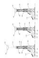
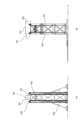
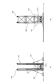
図26においてステップS34(図14のステップS14に対応)を終えると、次いで、外側架台302の補強及び分割を行う(ステップS35)。具体的には、図16-図18に示すように、外側架台302の補強をするため、外側架台302の下部にアウトリガー402を設けたり、外側架台302の支柱の本数を増やしたりする。なお、アウトリガー402は外側架台302を構築する際に取り付けておくことで風車100の解体時の安定性を向上できる。また、外側架台302の補強が済んだら、外側架台302の正面側及び背面側の梁401や筋交い(正面側上段の筋交い、背面側上段・中段・下段の筋交い)を撤去する(「撤去工程」の一例)ことにより、外側架台302の両側面を残す。これにより、外側架台302の正面側及び背面側の梁401や筋交いが無くなり、内側架台301の上部301Aとともにナセル120を下降させる際に、ナセル120が梁401や筋交いと干渉しない。 After step S34 in FIG. 26 (corresponding to step S14 in FIG. 14) is completed, the outer frame 302 is reinforced and divided (step S35). Specifically, as shown in FIG. 16-FIG. 18, in order to reinforce the outer frame 302, outriggers 402 are provided at the bottom of the outer frame 302, and the number of pillars of the outer frame 302 is increased. The outriggers 402 can be attached when the outer frame 302 is constructed to improve the stability when the wind turbine 100 is dismantled. After the outer frame 302 has been reinforced, the beams 401 and braces (the upper braces on the front side, and the upper, middle, and lower braces on the rear side) on the front and rear sides of the outer frame 302 are removed (an example of a "removal process"), leaving both sides of the outer frame 302. This eliminates the need for beams 401 and braces on the front and rear sides of the outer frame 302, and when the nacelle 120 is lowered together with the upper portion 301A of the inner frame 301, the nacelle 120 does not interfere with the beams 401 or braces.

次に、内側架台301に対する内側架台用ジャッキ303の吊り替えを行う(ステップS36)。具体的には、図16に示すように、4台の内側架台用ジャッキ303のフック403は、それぞれ内側架台301をせり上げるために内側架台301の下端部に取り付けられているので、これらを一度外して巻き上げた後、図18に示すように、内側架台301の上部301Aに取り付けることにより吊り替えを行う。これにより、ステップS37において内側架台301の下部(上部301Aより下の部分)を解体しても、上部301Aが落下することがない。 Next, the inner frame jacks 303 are resuspended from the inner frame 301 (step S36). Specifically, as shown in FIG. 16, the hooks 403 of the four inner frame jacks 303 are attached to the lower end of the inner frame 301 in order to raise the inner frame 301. After these hooks are removed and lifted up, the inner frame jacks 303 are resuspended by attaching them to the upper part 301A of the inner frame 301 as shown in FIG. 18. This prevents the upper part 301A from falling even if the lower part of the inner frame 301 (the part below the upper part 301A) is dismantled in step S37.

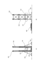
次に、内側架台301の下部を解体する(ステップS37。「第1架台解体工程」の一例)。これにより、図18に示すように、内側架台301の下部が無くなり、内側架台301の上部301Aがナセル120とともに内側架台用ジャッキ303に吊られた状態となる。 Next, the lower part of the inner frame 301 is dismantled (step S37, an example of the "first frame dismantling process"). As a result, as shown in FIG. 18, the lower part of the inner frame 301 is removed, and the upper part 301A of the inner frame 301 is suspended together with the nacelle 120 from the inner frame jack 303.

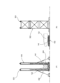
次に、図20、図21(A)、(B)に示すように、内側架台用ジャッキ303により、内側架台301の上部301Aをナセル120とともに地上まで下降させる(ステップS38)(「架台上部下降工程」の一例)。 Next, as shown in Figures 20, 21 (A) and (B), the upper part 301A of the inner frame 301 is lowered to the ground together with the nacelle 120 by the inner frame jack 303 (step S38) (an example of the "upper frame lowering process").

次に、図22に示すように、ナセル120が載置されている、内側架台301の上部301Aの梁(ナセル搬出用梁404)に内側架台用ジャッキ303のフック403を取り付け、ナセル搬出用梁404(「載置部」の一例)を残して、内側架台301の上部301Aを解体・撤去する(ステップS39)。 Next, as shown in FIG. 22, the hook 403 of the inner frame jack 303 is attached to the beam (nacelle removal beam 404) of the upper part 301A of the inner frame 301 on which the nacelle 120 is placed, and the upper part 301A of the inner frame 301 is dismantled and removed, leaving behind the nacelle removal beam 404 (an example of a "placement part") (step S39).

次に、ナセル120を搬出する(ステップS40)。具体的には、図23に示すように、ナセル搬出用梁404の下方にナセル搬出用車両405を搬入し、次いで、図24に示すように、内側架台用ジャッキ303によりナセル搬出用梁404とともにナセル120を下降させてナセル搬出用車両405に積載し、次いで、図25に示すように、ナセル搬出用車両405でナセル搬出用梁404とともにナセル120を搬出する。ナセル120は、ナセル搬出用車両405によりナセル解体場所まで運搬し、解体する。 Next, the nacelle 120 is removed (step S40). Specifically, as shown in FIG. 23, the nacelle removal vehicle 405 is brought in below the nacelle removal beam 404, and then, as shown in FIG. 24, the nacelle 120 is lowered together with the nacelle removal beam 404 by the inner frame jack 303 and loaded onto the nacelle removal vehicle 405, and then, as shown in FIG. 25, the nacelle 120 is removed together with the nacelle removal beam 404 by the nacelle removal vehicle 405. The nacelle 120 is transported by the nacelle removal vehicle 405 to a nacelle dismantling site and dismantled.

次に、外側架台302を解体・撤去する(ステップS41)。 Next, the outer frame 302 is dismantled and removed (step S41).

以上説明したように、変形例における、風車100の解体方法は、風車100のタワー110を囲う位置に構築される内側架台301(「第1架台」の一例)と、タワー110を囲う位置であって内側架台301の外側に構築される外側架台302(「第2架台」の一例)と、外側架台302に設けられ、内側架台301を昇降させる内側架台用ジャッキ303(「架台用昇降手段」の一例)と、内側架台301に設けられ、タワー110を構成する複数のタワー部材111のうち最下段にあるタワー部材111より上にあるその他のタワー部材111を吊った状態で昇降させる上ジャッキ310(「第1昇降手段」の一例)と、内側架台301に設けられ、最下段にあるタワー部材111を吊った状態で昇降させる下ジャッキ311(「第2昇降手段」の一例)と、を備え、内側架台301が、その頂部に、タワー部材111A(「最上段のタワー部材」の一例)の上部に設置されたナセル120を載置可能な載置部を有する風車施工用架台300を用いた風車100の解体方法であって、最下段にあるタワー部材111と、最下段から一段上にあるタワー部材111を分割する解体工程10(「分割工程」の一例)と、内側架台301が外側架台302に対してせり上がった状態で、上ジャッキ310により最下段にあるタワー部材111より上にある風車100の部材の荷重を支持する解体工程11(「支持工程」の一例)と、上ジャッキ310により荷重を支持している状態で、下ジャッキ311により最下段にあるタワー部材111を支持しつつ、風車施工用架台300から搬出する解体工程14及び解体工程15(「搬出工程」の一例)と、解体工程14及び解体工程15の後に、上ジャッキ310により搬出したタワー部材111より上のその他のタワー部材111を下降させる解体工程17(「風車部材下降工程」の一例)と、解体工程17によりナセル120が載置部に載置された場合に、タワー部材111Aとナセル120を切り離す解体工程19(「切り離し工程」の一例)と、ナセル120が載置部に載置された状態で、内側架台用ジャッキ303がせり上がった状態の内側架台301を下降させる解体工程21(「架台下降工程」の一例)と、工程21の後に、ナセル120が載置部に載置された状態で、内側架台301の上部301Aを残して下部を解体する工程(ステップS37。「第1架台解体工程」の一例)と、内側架台301の下部を解体する工程の後に、ナセル120が載置部に載置された状態で、内側架台用ジャッキ303が内側架台301の上部301Aを更に下降させる工程(ステップS38。「架台上部下降工程」の一例)と、を含む。 As described above, the method of dismantling the wind turbine 100 in the modified example includes an inner frame 301 (an example of a "first frame") constructed in a position surrounding the tower 110 of the wind turbine 100, an outer frame 302 (an example of a "second frame") constructed in a position surrounding the tower 110 and outside the inner frame 301, an inner frame jack 303 (an example of a "frame lifting means") provided on the outer frame 302 and used to raise and lower the inner frame 301, and an upper jack 310 (an example of a "first lifting means") provided on the inner frame 301 and used to lift and lower the other tower members 111 above the lowest tower member 111 among the multiple tower members 111 that make up the tower 110 while suspending them. The method for dismantling a wind turbine 100 uses a wind turbine construction stand 300, the wind turbine construction stand 300 including a lower jack 311 (an example of a "second lifting means") provided on the inner stand 301 and lifting and lowering the tower member 111 at the lowest level while it is suspended, the inner stand 301 having a mounting portion at its top capable of mounting a nacelle 120 installed at the top of the tower member 111A (an example of a "topmost tower member"), the method including a dismantling step 10 (an example of a "division step") of dividing the tower member 111 at the lowest level and the tower member 111 one level above the lowest level, and a lower jack 310 lifting and lowering the tower member 111 at the lowest level while the inner stand 301 is raised up relative to the outer stand 302. Dismantling process 11 (an example of a "supporting process") in which the load of the components of the wind turbine 100 above a certain tower component 111 is supported; dismantling process 14 and dismantling process 15 (an example of a "carrying out process") in which, while the load is supported by the upper jacks 310, the lowest tower component 111 is supported by the lower jacks 311 and transported out of the wind turbine construction frame 300; dismantling process 17 (an example of a "wind turbine component lowering process") in which, after dismantling process 14 and dismantling process 15, other tower components 111 above the tower component 111 carried out by the upper jacks 310 are lowered; and, when the nacelle 120 is placed on the mounting section in dismantling process 17, the tower component 111A and It includes a dismantling step 19 (an example of a "disconnecting step") in which the nacelle 120 is separated, a dismantling step 21 (an example of a "mount lowering step") in which the inner frame jack 303 lowers the inner frame 301 in the raised state while the nacelle 120 is placed on the mounting part, a step after step 21 in which the lower part of the inner frame 301 is dismantled while leaving the upper part 301A of the inner frame 301 remaining while the nacelle 120 is placed on the mounting part (step S37, an example of a "first frame dismantling step"), and a step after the step of dismantling the lower part of the inner frame 301 in which the inner frame jack 303 further lowers the upper part 301A of the inner frame 301 while the nacelle 120 is placed on the mounting part (step S38, an example of a "mount upper part lowering step").

したがって、変形例における、風車100の解体方法によれば、内側架台用ジャッキ303により内側架台301の上部301Aとともにナセル120を地上付近まで下降させることから、ナセル120の解体を高所で行う場合よりも安全に行うことができる。 Therefore, according to the method for dismantling the wind turbine 100 in the modified example, the nacelle 120 is lowered to near the ground together with the upper part 301A of the inner frame 301 by the inner frame jack 303, so that the dismantling of the nacelle 120 can be carried out more safely than if it were carried out at a high altitude.

また、変形例における、風車100の解体方法は、内側架台301の上部301Aを下降させる工程(ステップS38)の前に、内側架台301の上部301Aを下降させる際に干渉する、外側架台302の梁401や筋交い(「部材」の一例)を撤去する工程(ステップS38。「撤去工程」の一例)を含む。これにより、内側架台用ジャッキ303により内側架台301の上部301Aを下降させる際に、外側架台302の梁401や筋交いと、ナセル120が接触することを防ぐことができる。 In addition, the method of dismantling the wind turbine 100 in the modified example includes a step (step S38, an example of a "removal step") of removing the beams 401 and braces (an example of "components") of the outer frame 302 that interfere when the upper part 301A of the inner frame 301 is lowered before the step (step S38) of lowering the upper part 301A of the inner frame 301. This makes it possible to prevent the beams 401 and braces of the outer frame 302 from coming into contact with the nacelle 120 when the upper part 301A of the inner frame 301 is lowered by the inner frame jack 303.

[5.2.変形例における風車100の組立方法]
次に、図27等を用いて、変形例における風車100の組立方法について説明するが、基本的には、上述した変形例における風車100の解体方法を逆手順で行う。なお、図27に示すように、変形例におけるステップS77-ステップS88は、上記実施形態におけるステップS55-ステップS66(図15参照)と同様なので説明を省略する。
[5.2. Assembly method of the wind turbine 100 in the modified example]
Next, a method for assembling the wind turbine 100 in the modified example will be described with reference to Figure 27 etc., but basically, the method for dismantling the wind turbine 100 in the modified example described above is performed in reverse order. Note that, as shown in Figure 27, steps S77 to S88 in the modified example are similar to steps S55 to S66 (see Figure 15) in the above embodiment, and therefore description thereof will be omitted.

まず、風車100の設置位置に外側架台302を構築する(ステップS71)。このとき、内側架台301の上部301Aとナセル120を上昇させる際に干渉しないように、正面側及び背面側の梁401は設けない。つまり、外側架台302を左右に分割した状態で構築する。また、外側架台302の下には、架台用マット304及び架台用ガーダー305を設けることとする。 First, the outer frame 302 is constructed at the installation position of the wind turbine 100 (step S71). At this time, the beams 401 are not provided on the front and rear sides so that the upper part 301A of the inner frame 301 does not interfere with the nacelle 120 when it is raised. In other words, the outer frame 302 is constructed in a state where it is divided into left and right halves. In addition, a frame mat 304 and a frame girder 305 are provided under the outer frame 302.

次に、外側架台302の内側に内側架台301の上部301Aを構築し(「架台上部構築工程」の一例)、その上にナセル120を載置・固定する(ステップS72)。ナセル120は、先に構築した内側架台301の上部301A上で構築してもよい。また、予め構築したナセル120をナセル搬出用車両405とナセル搬出用梁404(「載置部」の一例)を用いて外側架台302の内側に搬入し、次いで、ナセル搬出用梁404及びナセル120を内側架台用ジャッキ303で吊り上げ、ナセル搬出用梁404を上部301Aの一部として上部301Aを構築してもよい。 Next, the upper part 301A of the inner frame 301 is constructed inside the outer frame 302 (an example of an "upper frame construction process"), and the nacelle 120 is placed and fixed on it (step S72). The nacelle 120 may be constructed on the upper part 301A of the inner frame 301 constructed previously. Alternatively, the previously constructed nacelle 120 may be carried inside the outer frame 302 using a nacelle transport vehicle 405 and a nacelle transport beam 404 (an example of a "mounting unit"), and then the nacelle transport beam 404 and the nacelle 120 may be lifted by the inner frame jack 303, and the nacelle transport beam 404 may be used as part of the upper part 301A to construct the upper part 301A.

次に、内側架台用ジャッキ303により、内側架台301の上部301Aをナセル120とともに上昇させる(ステップS73)。なお、予め、内側架台301の上部301Aに4台の内側架台用ジャッキ303のフック403を取り付けておくこととする。 Next, the upper portion 301A of the inner frame 301 is raised together with the nacelle 120 by the inner frame jack 303 (step S73). Note that the hooks 403 of the four inner frame jacks 303 are attached to the upper portion 301A of the inner frame 301 in advance.

次に、内側架台301の下部(上部301Aより下の部分)を構築する(ステップS74)。このとき、内側架台301の下部は架台用ガーダー305に接地させ、内側架台301及びナセル120の荷重を地面で受けるようにする。 Next, the lower part of the inner frame 301 (the part below the upper part 301A) is constructed (step S74). At this time, the lower part of the inner frame 301 is grounded on the frame girder 305 so that the load of the inner frame 301 and the nacelle 120 is supported by the ground.

次に、内側架台301の内側架台用ジャッキ303の吊り替えを行う(ステップS75)。具体的には、4台の内側架台用ジャッキ303のフック403は、内側架台301の上部301Aに取り付けられているので、これらを一度外して下降させた後、図16に示すように、内側架台301の下端部に取り付けることにより、吊り替えを行う。 Next, the inner frame jacks 303 of the inner frame 301 are resuspended (step S75). Specifically, the hooks 403 of the four inner frame jacks 303 are attached to the upper part 301A of the inner frame 301, so they are first removed and lowered, and then resuspended by attaching them to the lower end of the inner frame 301 as shown in FIG. 16.

次に、分割された状態の外側架台302を統合し、次いで、内側架台用ジャッキ303により内側架台301が外側架台302に対してせり上がった状態まで内側架台301をナセル120とともに上昇させる(ステップS76)。外側架台302を統合は、正面側及び背面側の梁401を取り付けることにより統合する。次いで、ステップS77の工程に移る。 Next, the divided outer frame 302 is integrated, and then the inner frame 301 is raised together with the nacelle 120 by the inner frame jack 303 until the inner frame 301 is raised above the outer frame 302 (step S76). The outer frame 302 is integrated by attaching the beams 401 on the front and rear sides. Then, the process proceeds to step S77.

以上説明したように、変形例における、風車100の組立方法は、風車100のタワー110を囲う位置に構築される内側架台301(「第1架台」の一例)と、タワー110を囲う位置であって内側架台301の外側に構築される外側架台302(「第2架台」の一例)と、外側架台302に設けられ、内側架台301を昇降させる内側架台用ジャッキ303(「架台用昇降手段」の一例)と、内側架台301に設けられ、タワー110を構成する複数のタワー部材111のうち一部のタワー部材111を吊った状態で昇降させる上ジャッキ310(「第1昇降手段」の一例)と、内側架台301に設けられ、一部のタワー部材より下に配置されるその他のタワー部材111を吊った状態で昇降させる下ジャッキ311(「第2昇降手段」の一例)と、を備え、内側架台301が、その頂部に、タワー部材111A(「最上段のタワー部材」の一例)の上部に設置されたナセル120を載置可能な載置部を有する風車施工用架台300を用いた風車100の組立方法であって、載置部を有する、内側架台301の上部301Aを構築する工程(ステップS72。「架台上部構築工程」の一例)と、ナセル120が載置部に載置された状態で、内側架台用ジャッキ303が内側架台301の上部301Aを上昇させる工程(ステップS73。「架台上部上昇工程」の一例)と、内側架台301の上部301Aを上昇させる工程の後に、内側架台301の上部301Aに対して内側架台301の下部を構築する工程(ステップS74。「架台下部構築工程」の一例)と、内側架台301の下部を構築する工程の後に、ナセル120が載置部に載置された状態で、内側架台用ジャッキ303が、内側架台301が外側架台302に対してせり上がった状態まで内側架台301を上昇させる工程(ステップS76。「架台上昇工程」の一例)と、内側架台301を上昇させる工程の後に、上ジャッキ310によりタワー部材111Aをナセル120と接合可能な位置まで吊り上げ、タワー部材111Aとナセル120を接合する組立工程7、組立工程8(「ナセル接合工程」の一例)と、内側架台301が外側架台302に対してせり上がった状態で、上ジャッキ310により一部のタワー部材111を吊り上げる組立工程7、組立工程13(「吊り上げ工程」の一例)と、上ジャッキ310により吊り上げられた一部のタワー部材の下方に、下ジャッキ311によりその他のタワー部材111を吊った状態で配置する組立工程9、組立工程14(「配置工程」の一例)と、上ジャッキ310により一部のタワー部材111を下降させ、組立工程9、組立工程14で配置されたその他のタワー部材111の上に載置する組立工程10、組立工程15(「載置工程」の一例)と、組立工程10、組立工程15の後に、一部のタワー部材111とその他のタワー部材111を接合する組立工程11、組立工程16(「タワー部材接合工程」の一例)と、を含む。 As described above, the method of assembling the wind turbine 100 in the modified example includes an inner frame 301 (an example of a "first frame") constructed in a position surrounding the tower 110 of the wind turbine 100, an outer frame 302 (an example of a "second frame") constructed in a position surrounding the tower 110 and outside the inner frame 301, an inner frame jack 303 (an example of a "frame lifting means") provided on the outer frame 302 and used to raise and lower the inner frame 301, an upper jack 310 (an example of a "first lifting means") provided on the inner frame 301 and used to lift and lower some of the tower members 111 that constitute the tower 110 in a suspended state, and an upper jack 310 (an example of a "first lifting means") provided on the inner frame 301 and used to lift and lower other tower members 111 that are located below the some of the tower members in a suspended state. a lower jack 311 (an example of a "second lifting means") for lifting and lowering the inner frame 301 in a state in which the nacelle 120 is placed on the top of a tower member 111A (an example of a "topmost tower member"), and the inner frame 301 has a mounting portion at its top, on which the nacelle 120 installed on the top of the tower member 111A (an example of a "topmost tower member") can be placed, the method including a step of constructing the upper portion 301A of the inner frame 301 having the mounting portion (step S72, an example of a "mount upper portion construction step"); a step of the inner frame jack 303 lifting the upper portion 301A of the inner frame 301 with the nacelle 120 placed on the mounting portion (step S73, an example of a "mount upper portion lifting step"); and a step of constructing the lower part of the side frame 301 (step S74, an example of a "frame lower part construction step"); a step of, after the step of constructing the lower part of the inner frame 301, using the inner frame jack 303 to raise the inner frame 301 to a state in which the inner frame 301 is raised above the outer frame 302 with the nacelle 120 placed on the placement section (step S76, an example of a "frame raising step"); assembly steps 7 and 8 (an example of a "nacelle joining step"), after the step of raising the inner frame 301, using the upper jack 310 to lift the tower member 111A to a position where it can be joined to the nacelle 120 and join the tower member 111A to the nacelle 120; The assembly process includes assembly process 7 and assembly process 13 (an example of a "lifting process") in which some of the tower members 111 are lifted by the upper jacks 310, assembly process 9 and assembly process 14 (an example of an "arrangement process") in which the other tower members 111 are placed in a suspended state by the lower jacks 311 below the some of the tower members lifted by the upper jacks 310, assembly process 10 and assembly process 15 (an example of a "placement process") in which some of the tower members 111 are lowered by the upper jacks 310 and placed on the other tower members 111 placed in assembly process 9 and assembly process 14, and assembly process 11 and assembly process 16 (an example of a "tower member joining process") in which some of the tower members 111 are joined to the other tower members 111 after assembly process 10 and assembly process 15.

したがって、変形例における、風車100の組立方法によれば、地上付近で組み立てたナセル120を、内側架台用ジャッキ303により内側架台301の上部301Aとともに上昇させることから、ナセル120の組み立てを高所で行う場合よりも安全に行うことができる。 Therefore, according to the method of assembling the wind turbine 100 in the modified example, the nacelle 120 assembled near the ground is raised together with the upper part 301A of the inner frame 301 by the inner frame jack 303, so that the assembly of the nacelle 120 can be carried out more safely than if it were carried out at a high altitude.

なお、変形例では、図16-図18に示すように、外側架台302の補強をするため、外側架台302の下部にアウトリガー402を設けたり、外側架台302の支柱の本数を増やしたりしたが、これに代えて、図28に示すように、外側架台302の外側の左右にそれぞれ補強架台410を構築することとしてもよい。左右の補強架台410は、それぞれ、2本(正面側と背面側に1本ずつ)の補強支柱412と、補強支柱412と外側架台302を接続する補強梁411と、筋交い413と、正面側の補強支柱412と背面側の補強支柱412を接続する補強梁414と、補強支柱412に固定されるアウトリガー402と、を含む。補強梁411は、外側架台302の支柱と補強支柱412の間に水平に設けられる。また、補強支柱412は、底部が基礎に固定されている。補強架台410を構築することで、外側架台302の強度を高めることができる。 In the modified example, as shown in Figs. 16-18, in order to reinforce the outer frame 302, outriggers 402 are provided at the bottom of the outer frame 302, and the number of pillars of the outer frame 302 is increased. Alternatively, as shown in Fig. 28, reinforcing frames 410 may be constructed on the left and right of the outer side of the outer frame 302. The left and right reinforcing frames 410 each include two reinforcing pillars 412 (one on the front side and one on the rear side), a reinforcing beam 411 connecting the reinforcing pillars 412 to the outer frame 302, a diagonal brace 413, a reinforcing beam 414 connecting the reinforcing pillars 412 on the front side and the reinforcing pillars 412 on the rear side, and an outrigger 402 fixed to the reinforcing pillars 412. The reinforcing beam 411 is provided horizontally between the pillars of the outer frame 302 and the reinforcing pillars 412. In addition, the bottom of the reinforcing column 412 is fixed to the foundation. By constructing the reinforcing frame 410, the strength of the outer frame 302 can be increased.

1 吊治具
2 吊治具本体
2A、2B 本体部材
3 吊板
3A 挿通孔
4 吊ピース
4A 挿通孔
11 チェーンブロック
12 チェーンブロック取付ワイヤー
13 吊ワイヤー
14 治具受け具
21 チルクライマー
22 チルクライマー取付ワイヤー
23 吊ワイヤー
30 クレーン
30A ブーム
31 吊りワイヤー
100 風車
110 タワー
111(111A、111B、111C) タワー部材
120 ナセル
130(130A、130B、130C) ブレード
131 フランジ
140 ハブ
201 ゴンドラ
202 ゴンドラ用ワイヤー
300 風車施工用架台
301 内側架台
302 外側架台
303 内側架台用ジャッキ
304 架台用マット
305 架台用ガーダー
306 ジャッキベース
307 下段フレーム
308 中段支持材
309 上段支持材
310 上ジャッキ
311 下ジャッキ
312 鋼材
313 吊具
314 吊ワイヤー
315 台車
401 梁
402 アウトリガー
403 フック
404 ナセル搬出用梁
405 ナセル搬出用車両
410 補強架台
411 補強梁
412 補強支柱
413 筋交い
1 Lifting jig 2 Lifting jig body 2A, 2B Body member 3 Lifting plate 3A Insertion hole 4 Lifting piece 4A Insertion hole 11 Chain block 12 Chain block mounting wire 13 Lifting wire 14 Jig receiver 21 Climbing rod 22 Climbing rod mounting wire 23 Lifting wire 30 Crane 30A Boom 31 Lifting wire 100 Wind turbine 110 Tower 111 (111A, 111B, 111C) Tower member 120 Nacelle 130 (130A, 130B, 130C) Blade 131 Flange 140 Hub 201 Gondola 202 Gondola wire 300 Wind turbine construction stand 301 Inner stand 302 Outer stand 303 Inner stand jack 304 Stand mat 305 Stand girder 306 Jack base 307 Lower frame 308, middle support member 309, upper support member 310, upper jack 311, lower jack 312, steel member 313, hoisting device 314, hoisting wire 315, trolley 401, beam 402, outrigger 403, hook 404, beam for nacelle removal 405, vehicle for nacelle removal 410, reinforcing frame 411, reinforcing beam 412, reinforcing pillar 413, diagonal brace

Claims (3)

風車のタワーを囲う位置に構築される第1架台と、
前記タワーを囲う位置であって前記第1架台の外側に構築される第2架台と、
前記第2架台に設けられ、前記第1架台を昇降させる架台用昇降手段と、
前記第1架台に設けられ、前記タワーを構成する複数のタワー部材のうち最下段にある前記タワー部材より上にあるその他の前記タワー部材を吊った状態で昇降させる第1昇降手段と、
前記第1架台に設けられ、前記最下段にあるタワー部材を吊った状態で昇降させる第2昇降手段と、
を備え、前記第1架台が、その頂部に、最上段の前記タワー部材の上部に設置されたナセルを載置可能な載置部を有する風車施工用架台を用いた前記風車の解体方法であって、
前記最下段にあるタワー部材と、最下段から一段上にある前記タワー部材を分割する分割工程と、
前記第1架台が前記第2架台に対してせり上がった状態で、前記第1昇降手段により前記最下段にあるタワー部材より上にある前記風車の部材の荷重を支持する支持工程と、
前記支持工程により荷重を支持している状態で、前記第2昇降手段により前記最下段にあるタワー部材を支持しつつ、前記風車施工用架台から搬出する搬出工程と、
前記搬出工程の後に、前記第1昇降手段により前記その他のタワー部材を下降させる風車部材下降工程と、
前記風車部材下降工程により前記ナセルが前記載置部に載置された場合に、前記最上段のタワー部材と前記ナセルを切り離す切り離し工程と、
前記ナセルが前記載置部に載置された状態で、前記架台用昇降手段がせり上がった状態の前記第1架台を下降させる架台下降工程と、
前記架台下降工程の後に、前記ナセルが前記載置部に載置された状態で、前記第1架台の上部を残して下部を解体する第1架台解体工程と、
前記第1架台解体工程の後に、前記ナセルが前記載置部に載置された状態で、前記架台用昇降手段が前記第1架台の上部を更に下降させる架台上部下降工程と、
を含むことを特徴とする風車の解体方法。
A first frame constructed in a position surrounding the wind turbine tower;
A second rack constructed at a position surrounding the tower and outside the first rack;
a platform lifting means provided on the second platform for lifting and lowering the first platform;
a first lifting means provided on the first frame for lifting and lowering the tower members above the lowest tower member among the plurality of tower members constituting the tower in a suspended state;
a second lifting means provided on the first frame for lifting and lowering the tower member at the lowest stage while the tower member is suspended;
The first frame has a mounting portion at its top on which a nacelle installed at the top of the uppermost tower member can be mounted,
a dividing step of dividing the tower member at the lowest level and the tower member one level above the lowest level;
a supporting step of supporting a load of the wind turbine components above the lowest tower component by the first lifting means in a state in which the first frame is elevated relative to the second frame;
a carrying-out process of carrying out the tower member at the lowest stage from the wind turbine construction frame while supporting the tower member at the lowest stage by the second lifting means in a state in which the load is supported by the supporting process;
a wind turbine member lowering step of lowering the other tower members by the first lifting means after the carrying-out step;
a separation process of separating the uppermost tower member from the nacelle when the nacelle is placed on the placement section by the wind turbine member lowering process;
a platform lowering step of lowering the first platform in a raised state by the platform lifting means while the nacelle is placed on the platform;
a first frame dismantling step of dismantling a lower part of the first frame while leaving an upper part of the first frame, with the nacelle placed on the placement section after the frame lowering step;
a frame upper part lowering step in which, after the first frame dismantling step, the frame lifting means further lowers an upper part of the first frame with the nacelle placed on the placement section;
A method for dismantling a wind turbine, comprising:
請求項1に記載の風車の解体方法であって、
前記架台上部下降工程の前に、前記第1架台の上部を下降させる際に干渉する、前記第2架台の部材を撤去する撤去工程を更に含むことを特徴とする風車の解体方法。
A method for dismantling a wind turbine according to claim 1,
The method for dismantling a wind turbine, further comprising, before the step of lowering the upper part of the frame, a removal step of removing members of the second frame that interfere when the upper part of the first frame is lowered.
風車のタワーを囲う位置に構築される第1架台と、
前記タワーを囲う位置であって前記第1架台の外側に構築される第2架台と、
前記第2架台に設けられ、前記第1架台を昇降させる架台用昇降手段と、
前記第1架台に設けられ、前記タワーを構成する複数のタワー部材のうち一部の前記タワー部材を吊った状態で昇降させる第1昇降手段と、
前記第1架台に設けられ、前記一部のタワー部材より下に配置されるその他の前記タワー部材を吊った状態で昇降させる第2昇降手段と、
を備え、前記第1架台が、その頂部に、最上段の前記タワー部材の上部に設置されたナセルを載置可能な載置部を有する風車施工用架台を用いた前記風車の組立方法であって、
前記載置部を有する、前記第1架台の上部を構築する架台上部構築工程と、
前記ナセルが前記載置部に載置された状態で、前記架台用昇降手段が前記第1架台の上部を上昇させる架台上部上昇工程と、
前記架台上部上昇工程の後に、前記第1架台の上部に対して前記第1架台の下部を構築する架台下部構築工程と、
前記架台下部構築工程の後に、前記ナセルが前記載置部に載置された状態で、前記架台用昇降手段が、前記第1架台を上昇させる架台上昇工程と、
前記架台上昇工程の後に、前記第1昇降手段により最上段の前記タワー部材を前記ナセルと接合可能な位置まで吊り上げ、前記最上段のタワー部材と前記ナセルを接合するナセル接合工程と、
前記第1架台が前記第2架台に対してせり上がった状態で、前記第1昇降手段により前記一部のタワー部材を吊り上げる吊り上げ工程と、
前記第1昇降手段により吊り上げられた前記一部のタワー部材の下方に、前記第2昇降手段により前記その他のタワー部材を吊った状態で配置する配置工程と、
前記第1昇降手段により前記一部のタワー部材を下降させ、前記配置工程で配置された前記その他のタワー部材の上に載置する載置工程と、
前記載置工程の後に、前記一部のタワー部材と前記その他のタワー部材を接合するタワー部材接合工程と、を含むことを特徴とする風車の組立方法。
A first frame constructed in a position surrounding the wind turbine tower;
A second rack constructed at a position surrounding the tower and outside the first rack;
a platform lifting means provided on the second platform for lifting and lowering the first platform;
a first lifting means provided on the first frame and configured to lift and lower a part of the tower members among a plurality of tower members constituting the tower in a suspended state;
A second lifting means is provided on the first frame and lifts and lowers the other tower members that are arranged below the part of the tower members in a suspended state;
The first frame has a mounting portion at its top on which a nacelle installed at the top of the uppermost tower member can be mounted,
a frame upper part construction process for constructing an upper part of the first frame having the mounting portion;
a frame upper portion raising step in which the frame lifting means raises an upper portion of the first frame in a state in which the nacelle is placed on the placement section;
a frame lower part construction step of constructing a lower part of the first frame relative to an upper part of the first frame after the frame upper part lifting step;
a frame lifting step in which, after the frame lower part construction step, the frame lifting means lifts the first frame in a state in which the nacelle is placed on the placement part;
a nacelle joining step of lifting the uppermost tower member by the first lifting means to a position where the uppermost tower member can be joined to the nacelle after the frame lifting step, and joining the uppermost tower member to the nacelle;
a lifting process of lifting the part of the tower members by the first lifting means in a state in which the first frame is elevated relative to the second frame;
a placement step of placing the other tower members in a suspended state by the second lifting means below the part of the tower members lifted by the first lifting means;
a placing step of lowering the part of the tower members by the first lifting means and placing the part of the tower members on the other tower members arranged in the placing step;
a tower member joining step of joining the part of the tower members to the other tower members after the placing step.
JP2022169172A 2022-10-21 2022-10-21 Method for dismantling and assembling a wind turbine Active JP7586877B2 (en)

Priority Applications (1)

Application Number Priority Date Filing Date Title
JP2022169172A JP7586877B2 (en) 2022-10-21 2022-10-21 Method for dismantling and assembling a wind turbine

Applications Claiming Priority (1)

Application Number Priority Date Filing Date Title
JP2022169172A JP7586877B2 (en) 2022-10-21 2022-10-21 Method for dismantling and assembling a wind turbine

Publications (2)

Publication Number Publication Date
JP2024061311A JP2024061311A (en) 2024-05-07
JP7586877B2 true JP7586877B2 (en) 2024-11-19

Family

ID=90925370

Family Applications (1)

Application Number Title Priority Date Filing Date
JP2022169172A Active JP7586877B2 (en) 2022-10-21 2022-10-21 Method for dismantling and assembling a wind turbine

Country Status (1)

Country Link
JP (1) JP7586877B2 (en)

Citations (4)

* Cited by examiner, † Cited by third party
Publication number Priority date Publication date Assignee Title
JP2005042313A (en) 2003-07-22 2005-02-17 Mitsubishi Heavy Ind Ltd Tower structure assembling method and tower structure assembling apparatus
JP2014020016A (en) 2012-07-12 2014-02-03 Taihei Dengyo Kaisha Ltd Construction method for towering structure
JP2021143599A (en) 2020-03-10 2021-09-24 太平電業株式会社 Tower member building-up method and lifting-up tool used for tower member building-up method
JP2022088204A (en) 2020-12-02 2022-06-14 ベステラ株式会社 Disassembly method of offshore tower type wind turbine generator system

Family Cites Families (1)

* Cited by examiner, † Cited by third party
Publication number Priority date Publication date Assignee Title
JPH07197696A (en) * 1993-12-31 1995-08-01 Nippon Concrete Ind Co Ltd Construction method of connection type columnar body

Patent Citations (4)

* Cited by examiner, † Cited by third party
Publication number Priority date Publication date Assignee Title
JP2005042313A (en) 2003-07-22 2005-02-17 Mitsubishi Heavy Ind Ltd Tower structure assembling method and tower structure assembling apparatus
JP2014020016A (en) 2012-07-12 2014-02-03 Taihei Dengyo Kaisha Ltd Construction method for towering structure
JP2021143599A (en) 2020-03-10 2021-09-24 太平電業株式会社 Tower member building-up method and lifting-up tool used for tower member building-up method
JP2022088204A (en) 2020-12-02 2022-06-14 ベステラ株式会社 Disassembly method of offshore tower type wind turbine generator system

Also Published As

Publication number Publication date
JP2024061311A (en) 2024-05-07

Similar Documents

Publication Publication Date Title
CN113348289B (en) Multi-column wind turbine tower and erection method
JP2009113922A (en) Construction method of tower-like structure and construction crane
CN206692235U (en) A kind of steel structure dome lifts by crane erecting device
JP2020515484A (en) Winding system for wind turbine installation
CN209308175U (en) A kind of factory building roof rack mounting structure
JP7586877B2 (en) Method for dismantling and assembling a wind turbine
CN109440942A (en) A kind of factory building roof rack mounting structure and construction technology
US3998029A (en) Tower crane climbing
CN111852074B (en) Adjustable lifting type supporting device
EP3263891B1 (en) Method for mounting a wind turbine on a tower
CN119933344A (en) Installation method and removal method of internal construction platform of silo
EP0776404A1 (en) Crane for raising longitudinal bodies, foundation for such a crane and method for raising of longitudinal bodies by means of such a crane
JP3905103B2 (en) Tower-like building erection method and erection device
JP7174806B1 (en) Wind turbine dismantling method, wind turbine assembly method, and wind turbine construction stand
JP6438931B2 (en) Temporary column, temporary column installation structure, and roof frame construction method
JP6814717B2 (en) How to install horizontal members and how to build a building frame
JP2579715B2 (en) External tower crane
JP2011201691A (en) Simple assembly type derrick
CN215054431U (en) Unequal-diameter ring truss high-altitude sectional installation fixing device
JP3827321B1 (en) Windmill assembling apparatus and assembling method
JP2023131474A (en) Steel tower disassembly and assembly equipment, steel tower disassembly method, and steel tower assembly method
JP3242775B2 (en) Installation method of vertical container
CN209780399U (en) movable intelligent lifting radar tower
CN103121625A (en) Method for high altitude disassembly of large-scale part
JP7555840B2 (en) Tower crane transport unit and tower crane transport method

Legal Events

Date Code Title Description
A621 Written request for application examination

Free format text: JAPANESE INTERMEDIATE CODE: A621

Effective date: 20240314

TRDD Decision of grant or rejection written
A01 Written decision to grant a patent or to grant a registration (utility model)

Free format text: JAPANESE INTERMEDIATE CODE: A01

Effective date: 20241022

A977 Report on retrieval

Free format text: JAPANESE INTERMEDIATE CODE: A971007

Effective date: 20241024

A61 First payment of annual fees (during grant procedure)

Free format text: JAPANESE INTERMEDIATE CODE: A61

Effective date: 20241107

R150 Certificate of patent or registration of utility model

Ref document number: 7586877

Country of ref document: JP

Free format text: JAPANESE INTERMEDIATE CODE: R150