JP7586875B2 - Water recovery systems and power plants - Google Patents
Water recovery systems and power plants Download PDFInfo
- Publication number
- JP7586875B2 JP7586875B2 JP2022160927A JP2022160927A JP7586875B2 JP 7586875 B2 JP7586875 B2 JP 7586875B2 JP 2022160927 A JP2022160927 A JP 2022160927A JP 2022160927 A JP2022160927 A JP 2022160927A JP 7586875 B2 JP7586875 B2 JP 7586875B2
- Authority
- JP
- Japan
- Prior art keywords
- water
- recovered
- recovered water
- cooled cooler
- external
- Prior art date
- Legal status (The legal status is an assumption and is not a legal conclusion. Google has not performed a legal analysis and makes no representation as to the accuracy of the status listed.)
- Active
Links
- XLYOFNOQVPJJNP-UHFFFAOYSA-N water Substances O XLYOFNOQVPJJNP-UHFFFAOYSA-N 0.000 title claims description 778
- 238000011084 recovery Methods 0.000 title claims description 153
- 238000001816 cooling Methods 0.000 claims description 184
- 239000007789 gas Substances 0.000 claims description 60
- 239000006200 vaporizer Substances 0.000 claims description 37
- 239000003507 refrigerant Substances 0.000 claims description 33
- 239000002737 fuel gas Substances 0.000 claims description 32
- 239000000446 fuel Substances 0.000 claims description 29
- 230000008016 vaporization Effects 0.000 claims description 26
- 238000009834 vaporization Methods 0.000 claims description 21
- 239000002826 coolant Substances 0.000 claims description 18
- 238000003809 water extraction Methods 0.000 claims description 17
- 238000011144 upstream manufacturing Methods 0.000 claims description 11
- 239000007788 liquid Substances 0.000 claims description 6
- 238000005259 measurement Methods 0.000 claims description 6
- 230000001105 regulatory effect Effects 0.000 claims 2
- 230000001276 controlling effect Effects 0.000 claims 1
- 230000007423 decrease Effects 0.000 description 20
- 239000013535 sea water Substances 0.000 description 15
- 238000010586 diagram Methods 0.000 description 12
- 239000012535 impurity Substances 0.000 description 12
- 230000005856 abnormality Effects 0.000 description 8
- 239000003949 liquefied natural gas Substances 0.000 description 6
- 238000002485 combustion reaction Methods 0.000 description 5
- 230000006870 function Effects 0.000 description 5
- 230000014509 gene expression Effects 0.000 description 5
- 238000000034 method Methods 0.000 description 5
- 239000003921 oil Substances 0.000 description 5
- 230000008569 process Effects 0.000 description 5
- 239000000295 fuel oil Substances 0.000 description 4
- VNWKTOKETHGBQD-UHFFFAOYSA-N methane Chemical compound C VNWKTOKETHGBQD-UHFFFAOYSA-N 0.000 description 4
- 238000000605 extraction Methods 0.000 description 3
- 238000012423 maintenance Methods 0.000 description 3
- 238000010248 power generation Methods 0.000 description 3
- 238000012545 processing Methods 0.000 description 3
- 239000000498 cooling water Substances 0.000 description 2
- 230000000694 effects Effects 0.000 description 2
- 239000000945 filler Substances 0.000 description 2
- 239000003345 natural gas Substances 0.000 description 2
- 230000004044 response Effects 0.000 description 2
- NWUYHJFMYQTDRP-UHFFFAOYSA-N 1,2-bis(ethenyl)benzene;1-ethenyl-2-ethylbenzene;styrene Chemical compound C=CC1=CC=CC=C1.CCC1=CC=CC=C1C=C.C=CC1=CC=CC=C1C=C NWUYHJFMYQTDRP-UHFFFAOYSA-N 0.000 description 1
- QGZKDVFQNNGYKY-UHFFFAOYSA-N Ammonia Chemical compound N QGZKDVFQNNGYKY-UHFFFAOYSA-N 0.000 description 1
- NINIDFKCEFEMDL-UHFFFAOYSA-N Sulfur Chemical compound [S] NINIDFKCEFEMDL-UHFFFAOYSA-N 0.000 description 1
- 238000007664 blowing Methods 0.000 description 1
- 230000008859 change Effects 0.000 description 1
- 239000000567 combustion gas Substances 0.000 description 1
- 238000004891 communication Methods 0.000 description 1
- 230000003247 decreasing effect Effects 0.000 description 1
- 230000006866 deterioration Effects 0.000 description 1
- 238000007599 discharging Methods 0.000 description 1
- 238000006073 displacement reaction Methods 0.000 description 1
- 229910052739 hydrogen Inorganic materials 0.000 description 1
- 239000001257 hydrogen Substances 0.000 description 1
- 125000004435 hydrogen atom Chemical class [H]* 0.000 description 1
- 239000003456 ion exchange resin Substances 0.000 description 1
- 229920003303 ion-exchange polymer Polymers 0.000 description 1
- 239000003350 kerosene Substances 0.000 description 1
- 239000000463 material Substances 0.000 description 1
- 239000007800 oxidant agent Substances 0.000 description 1
- 229910052717 sulfur Inorganic materials 0.000 description 1
- 239000011593 sulfur Substances 0.000 description 1
Images


Landscapes
- Engine Equipment That Uses Special Cycles (AREA)
Description
本開示は、水回収システム、および、発電プラントに関する。 This disclosure relates to a water recovery system and a power generation plant.
従来、ボイラから排出される排ガスから水分を回収するための水回収システムが知られている。例えば特許文献1で開示される火力発電プラントは、ガスタービンと、ガスタービンから排出される排ガスから熱を回収する排熱回収ボイラと、排熱回収ボイラから排出される排ガス中の水分を回収する水回収システムとを備える。水回収システムは、上記排ガスと循環水との気液接触により水分を回収する接触式冷却塔と、接触式冷却塔から排出される上記水分を含む循環水を冷却する冷却熱交換器とを含む。
Conventionally, water recovery systems for recovering moisture from exhaust gas discharged from a boiler are known. For example, a thermal power plant disclosed in
同文献で開示される発電プラントは、液化天然ガスの気化処理によって得られる天然ガスをガスタービンの燃焼器に供給するLNG気化システムをさらに備える。LNG気化システムは、海から海水を取水する海水取水ラインと、海水取水ラインによって供給される海水を熱源として液化天然ガスを気化させる気化器と、気化器から排出される海水を冷却熱交換器に供給する海水排水ラインとを含む。冷却熱交換器は、海水排水ラインを流れる海水を冷却源として循環水を冷却する。 The power plant disclosed in the document further includes an LNG vaporization system that supplies natural gas obtained by vaporization of liquefied natural gas to the combustor of the gas turbine. The LNG vaporization system includes a seawater intake line that takes in seawater from the sea, a vaporizer that vaporizes liquefied natural gas using the seawater supplied by the seawater intake line as a heat source, and a seawater discharge line that supplies seawater discharged from the vaporizer to a cooling heat exchanger. The cooling heat exchanger cools the circulating water using seawater flowing through the seawater discharge line as a cooling source.
上記特許文献では、海から取水された海水がそのまま気化器に流入するので、気化器で利用される海水の温度が比較的低い。従って、規定量の天然ガスを生成するために必要となる海水の量が増えてしまうので、気化器に海水を供給するための動力が増大する。よって、発電プラントの運転効率が下がるおそれがある。 In the above patent document, seawater taken from the ocean flows directly into the vaporizer, so the temperature of the seawater used in the vaporizer is relatively low. This increases the amount of seawater required to produce a specified amount of natural gas, and increases the power required to supply seawater to the vaporizer. This may result in a decrease in the operating efficiency of the power plant.
本開示の目的は、発電プラントの運転効率を向上した水回収システム、および、それを備えた発電プラントを提供することである。 The objective of this disclosure is to provide a water recovery system that improves the operating efficiency of a power plant, and a power plant equipped with the same.
本開示の少なくとも一実施形態に係る水回収システムは、
発電プラントが備えるボイラから排出される排ガスから水分を回収するための水回収システムであって、
前記排ガスと冷媒水とを気液接触させることで前記排ガス中の前記水分を回収水として回収するための水回収装置と、
前記水回収装置から排出される前記回収水を前記発電プラントの外部から取水した外部水で冷却するための第1回収水冷却装置と、
前記水回収装置から排出される前記回収水を前記第1回収水冷却装置に導くとともに、前記第1回収水冷却装置によって冷却された前記回収水を前記冷媒水として前記水回収装置に導くための回収水循環ラインと、
前記第1回収水冷却装置から排出される前記外部水を、液化燃料ガスを気化させるための気化器へ供給する外部水供給ラインと、
を備える。
In accordance with at least one embodiment of the present disclosure, the water recovery system comprises:
A water recovery system for recovering moisture from exhaust gas discharged from a boiler of a power plant, comprising:
a water recovery device for recovering the moisture in the exhaust gas as recovered water by bringing the exhaust gas into gas-liquid contact with refrigerant water;
a first recovered water cooling device for cooling the recovered water discharged from the water recovery device with external water taken from outside the power plant;
a recovered water circulation line for guiding the recovered water discharged from the water recovery device to the first recovered water cooling device and guiding the recovered water cooled by the first recovered water cooling device to the water recovery device as the refrigerant water;
an external water supply line that supplies the external water discharged from the first recovered water cooling device to a vaporizer for vaporizing the liquefied fuel gas;
Equipped with.
本開示の一実施形態に係る発電プラントは、
前記気化器を含む液化燃料気化システムと、
前記液化燃料気化システムによって生成される燃料ガスが供給される燃焼器を含むガスタービンと、
ボイラ給水を貯める補給水タンクと、
前記ガスタービンから排出される前記排ガスから回収した熱を利用して、前記補給水タンクから供給される前記ボイラ給水から蒸気を生成するための前記ボイラである排熱回収ボイラと、
前記排熱回収ボイラから排出される前記排ガスから前記水分を回収するための、上記の水回収システムと、
を備える。
A power plant according to an embodiment of the present disclosure includes:
a liquefied fuel vaporization system including the vaporizer;
a gas turbine including a combustor supplied with fuel gas produced by the liquefied fuel vaporization system;
A make-up water tank for storing boiler feed water;
a heat recovery boiler that generates steam from the boiler feed water supplied from the make-up water tank by utilizing heat recovered from the exhaust gas discharged from the gas turbine;
The above water recovery system for recovering the moisture from the exhaust gas discharged from the heat recovery steam generator;
Equipped with.
本開示によれば、発電プラントの運転効率を向上した水回収システム、および、それを備えた発電プラントを提供できる。 The present disclosure provides a water recovery system that improves the operating efficiency of a power plant, and a power plant equipped with the same.
以下、添付図面を参照して本開示の幾つかの実施形態について説明する。ただし、実施形態として記載されている又は図面に示されている構成部品の寸法、材質、形状、その相対的配置等は、本開示の範囲をこれに限定する趣旨ではなく、単なる説明例にすぎない。
例えば、「ある方向に」、「ある方向に沿って」、「平行」、「直交」、「中心」、「同心」或いは「同軸」等の相対的或いは絶対的な配置を表す表現は、厳密にそのような配置を表すのみならず、公差、若しくは、同じ機能が得られる程度の角度や距離をもって相対的に変位している状態も表すものとする。
例えば、「同一」、「等しい」及び「均質」等の物事が等しい状態であることを表す表現は、厳密に等しい状態を表すのみならず、公差、若しくは、同じ機能が得られる程度の差が存在している状態も表すものとする。
例えば、四角形状や円筒形状等の形状を表す表現は、幾何学的に厳密な意味での四角形状や円筒形状等の形状を表すのみならず、同じ効果が得られる範囲で、凹凸部や面取り部等を含む形状も表すものとする。
一方、一の構成要素を「備える」、「含む」、又は、「有する」という表現は、他の構成要素の存在を除外する排他的な表現ではない。
なお、同様の構成については同じ符号を付し説明を省略することがある。
Hereinafter, some embodiments of the present disclosure will be described with reference to the accompanying drawings. However, the dimensions, materials, shapes, relative arrangements, etc. of components described as the embodiments or shown in the drawings are merely illustrative examples and are not intended to limit the scope of the present disclosure.
For example, expressions expressing relative or absolute configuration, such as "in a certain direction,""along a certain direction,""parallel,""orthogonal,""center,""concentric," or "coaxial," not only strictly express such a configuration, but also express a state in which there is a relative displacement with a tolerance or an angle or distance to the extent that the same function is obtained.
For example, expressions indicating that things are in an equal state, such as "identical,""equal," and "homogeneous," not only indicate a state of strict equality, but also indicate a state in which there is a tolerance or a difference to the extent that the same function is obtained.
For example, expressions describing shapes such as a rectangular shape or a cylindrical shape do not only refer to rectangular shapes, cylindrical shapes, etc. in the strict geometric sense, but also refer to shapes that include uneven portions, chamfered portions, etc., to the extent that the same effect is obtained.
On the other hand, the expressions "comprise", "include", or "have" a certain element are not exclusive expressions excluding the presence of other elements.
In addition, the same components are denoted by the same reference numerals and the description thereof may be omitted.
<1.発電プラント100の概要>
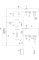
図1は、本開示の一実施形態に係る発電プラント100を示す概略図である。同図で例示されるガスタービンコジェネレーションシステムとしての発電プラント100は、大気6から圧縮空気7を生成するための圧縮機1と、圧縮空気7と燃料とが混合されるように構成される燃焼器3と、燃焼器3から排出される燃焼ガス12を駆動源として回転するためのガスタービン2と、ガスタービン2に連結される発電機5と、排熱回収ボイラ14とを備える。排熱回収ボイラ14は、ガスタービン2から排出される水分を含んだ排ガス13から回収した熱を利用してボイラ給水から蒸気を生成するように構成されるボイラである。なお、ボイラ給水は排熱回収ボイラ14に供給されるための水である。発電プラント100は、排熱回収ボイラ14から排出される排ガス13が流れるための主排気ダクト57をさらに備える。
1. Overview of
FIG. 1 is a schematic diagram showing a
本開示の必須の構成要素ではないが、発電プラント100は、排熱回収ボイラ14から排出される蒸気の温度を下げるための減温器22をさらに備える。減温器22は、例えば、排熱回収ボイラ14に供給されるボイラ給水の一部が冷水として流入するように構成されており(矢印B参照)、該冷水が減温器22の内部で噴射されることによって蒸気は冷まされる。冷まされた蒸気は、燃焼器3のヘッドエンド部に導かれ、圧縮空気7を酸化剤として燃焼器3内で燃料燃焼時に発生するサーマルNOxを抑制するように火炎領域に噴射される。
Although not an essential component of the present disclosure, the
本開示の一実施形態に係る燃焼器3には、燃料ガスまたは油燃料が選択的に供給可能である。具体的な一例として、発電プラント100は、燃料ガス供給ライン151、及び、油供給ライン152を備える。燃料ガス供給ライン151は、液化燃料ガスを気化させるための液化燃料気化システム50によって生成された燃料ガスを燃焼器3に供給する。液化燃料ガスは、一例として液化天然ガス(LNG;Liquefied Natural Gas)であるが、本開示はこれに限定されない。液化燃料ガスは、液体アンモニアまたは液体水素などであってもよい。油供給ライン152は、例えば重油または灯油などであってもよい油燃料を供給源8から燃焼器3に供給する。また、燃料ガス供給ライン151と油供給ライン152にはそれぞれ燃料供給弁151A,152Aが設けられる。燃料供給弁151A,152Aが選択的に開閉制御されることで、燃料ガスまたは油燃料のいずれかが燃焼器3に供給される。
The
燃焼器3では、燃料ガスまたは油燃料のいずれかと圧縮空気7とが混ざり、燃焼が起こる。燃焼による火炎中に上述の蒸気が噴射される。ガスタービン2からの排ガス13には、大気中水分、燃焼生成水分、および、蒸気噴射水分が含まれる。そして、排熱回収ボイラ14から排出される排ガス13に含まれる水分は、後述の水回収システム40によって回収される。水回収システム40にて水分を回収された排ガス13は系外に排出される(矢印A)。
In the
本例の発電プラント100は、補給水ライン15と、補給水ライン15から供給される補給水をボイラ給水として貯める補給水タンク17と、補給水タンク17と排熱回収ボイラ14とに接続される給水ライン19と、給水ライン19に設けられる給水ポンプ18とを備える。給水ポンプ18が駆動すると、補給水タンク17に貯留されるボイラ給水は給水ライン19を流れて排熱回収ボイラ14に供給される。排熱回収ボイラ14に供給されるボイラ給水の温度は高い方が好ましい。排熱回収ボイラ14が蒸気を生成するために必要とする熱量が低減し、発電プラント100の効率は向上するからである。
The
本開示の必須の構成要素ではないが、発電プラント100は、主排気ダクト57に連通する排気ダクト29と、排気ダクト29に設けられる通気ダンパ31と、排気ダクト29に連結される排気塔30とを備える。通気ダンパ31が開放されたときには、主排気ダクト57を流れる排ガス13は、排気ダクト29を経由して排気塔30から系外に排出される。また本開示の主排気ダクト57は水回収システム40にも連結されている。そして、通気ダンパ31が閉鎖されたときには、主排気ダクト57を流れる排ガス13は発電プラント100の構成要素である水回収システム40へと流れ、排ガス13に含まれる水分が回収される。
Although not a required component of the present disclosure, the
なお、上記の実施形態に係る発電プラント100は、ガスタービン2を備えるガスタービン発電プラントであるが、本開示はこれに限定されない。例えば、他の実施形態に係る発電プラント100は、蒸気タービンを備える汽力発電プラントであってもよい。
Note that the
<2.水回収システム40の概要>
図2は、本開示の一実施形態に係る水回収システム40を示す概略図である。水回収システム40の概要は以下の通りである。
2. Overview of the
2 is a schematic diagram showing a
水回収システム40の構成要素である水回収装置33は、排ガス13と冷媒水とを気液接触させることで排ガス13中の水分を回収水として回収するように構成される。より詳細な一例として、水回収装置33は、排ガス13と冷媒水とが流入する熱交換容器130と、熱交換容器130の内部で冷媒水を散水するための散水装置34と、熱交換容器130の内部で散水装置34の下方に位置する充填物35とを含む。散水装置34によって散水される冷媒水は充填物35に付着し、熱交換容器130に流入する排ガス13と熱交換を行う。これにより、排ガス13の水分が凝縮する。凝縮した水分と熱交換を終えた冷媒水とを含む回収水は落下し、熱交換容器130の下部を構成する貯水槽136に貯まる。
The
水回収システム40は、水回収装置33の貯水槽136から排出される回収水を冷却するための第1回収水冷却装置110と、水回収装置33の貯水槽136から排出される回収水を第1回収水冷却装置110に導くための回収水排出ライン39と、第1回収水冷却装置110から排出される冷却された回収水を冷媒水として水回収装置33に導くための回収水供給ライン42とをさらに備える。回収水供給ライン42と回収水排出ライン39は、水回収装置33と第1回収水冷却装置110の間で回収水を循環させる回収水循環ライン43として機能する。以下では説明の便宜上、回収水供給ライン42から水回収装置33の入口に流入した回収水を冷媒水という。
The
本例では、インバータ(図示外)を含む回収水ポンプ38が回収水排出ライン39に設けられており、回収水ポンプ38の回転数が水回収システム40の構成要素であるコントローラ90によって制御される。これにより、回収水循環ライン43における回収水の循環流量が制御される。本例では、水回収装置33から排出される排ガス13の温度が規定温度になるよう、回収水ポンプ38の回転数の制御を通じて回収水の循環流量が制御される。また本例では、排ガス13の温度が規定温度になるよう、第1回収水冷却装置110の出口における回収水の温度は制御される。第1回収水冷却装置110の出口における回収水の温度の制御は、第1回収水冷却装置110の冷却系統をコントローラ90が制御することで実現される。
In this example, a recovered
第1回収水冷却装置110の冷却系統を説明する。第1回収水冷却装置110は、発電プラント100の外部9から取水された外部水で回収水を冷却するように構成されている。本実施形態では、第1回収水冷却装置110にて回収水から熱を回収した外部水が、既述の液化燃料気化システム50を構成する気化器52に供給される。気化器52は外部水で液化燃料ガスを気化することで燃料ガスを生成し、生成された燃料ガスは既述の燃料ガス供給ライン151(図1参照)に排出される。なお、外部水は、例えば、海水、河川水、または、湖水などである。外部水が海水である場合には外部9は海であり、外部水が河川水である場合には外部9は河川であり、外部水が湖水である場合には外部9は湖である。
The cooling system of the first recovered
第1回収水冷却装置110の冷却系統の具体的な構成例は以下の通りである。水回収システム40は、外部9から得られる外部水が第1回収水冷却装置110に流入するための外部水流入ライン62と、第1回収水冷却装置110から排出される外部水を気化器52へ供給するための外部水供給ライン63とを備える。本例では、外部水流量調整弁73が外部水流入ライン62に設けられ、外部水開閉弁65が外部水流入ライン62と外部水供給ライン63の各々に設けられる。
他の例では、外部水流量調整弁73が外部水流入ライン62と外部水供給ライン63のそれぞれに設けられてもよいし、外部水供給ライン63のみに設けられてもよい。また、外部水開閉弁65は、外部水流入ライン62と外部水供給ライン63のいずれか一方のみに設けられてもよい。
A specific configuration example of the cooling system of the first recovered
In another example, the external water flow
上記構成によれば、第1回収水冷却装置110において回収水から熱を受領した外部水が外部水供給ライン63を経由して気化器52に流入する。気化器52に流入する外部水の温度が高まるので、規定の燃料ガスを生成するために気化器52において必要となる外部水の量を低減できる。気化器52に外部水を供給するための動力(例えば、図5に示す外部水を送るための外部水ポンプ55の動力)を低減できるので、発電プラント100の運転効率を向上させた水回収システム40が実現される。
According to the above configuration, the external water that has received heat from the recovered water in the first recovered
なお、本開示の必須の構成要素ではないが、図2で例示される水回収システム40は、回収水を補給水タンク17に導くための給水ライン4をさらに備え、給水ライン4は、高温給水ライン44と低温給水ライン47とを含む。高温給水ライン44は、回収水排出ライン39に接続されており、回収水排出ライン39から取り出された回収水を補給水タンク17に導くように構成される。回収水排出ライン39から取り出される回収水は、排ガス13から回収された熱を有するため、比較的高い温度を有する(本例では、回収水排出ライン39を流れる回収水の温度は60℃~70℃程度である。)。低温給水ライン47は、回収水供給ライン42に接続されており、回収水供給ライン42から取り出された回収水を補給水タンク17に導くように構成される。回収水供給ライン42から取り出される回収水は、第1回収水冷却装置110による冷却処理が施されているため、比較的低い温度を有する(本例では、回収水供給ライン42を流れる回収水の温度は40℃程度である。)。なお、回収水供給ライン42を流れる回収水は、第1回収水冷却装置110によって冷却処理が施されていることに限定されない。回収水供給ライン42を流れる回収水は、第1回収水冷却装置110に加えてあるいは第1回収水冷却装置110に代えて、後述する少なくとも1つの第2回収水冷却装置120(図3参照)によって冷却処理が施されていてもよい。
Although not an essential component of the present disclosure, the
低温給水ライン47には、水回収システム40の構成要素である水処理装置46が設けられている。水処理装置46は、低温給水ライン47を流れる回収水に対して例えば硫黄などの不純物を除去する処理を施すように構成される。不純物は燃焼器3(図1参照)での燃焼に伴って生じ、排ガス13に混入することがある。この不純物の少なくとも一部は、水回収装置33での排ガス13と冷媒水との熱交換により、回収水に溶解する。水処理装置46が、回収水に含まれる不純物を除去することで、補給水タンク17に貯留されるボイラ給水に不純物が含まれることが抑制される。一般に、処理される水の温度が低い方が、水処理装置46における不純物除去の処理能力は向上する。回収水の温度が高い場合、水処理装置46を構成するイオン交換樹脂146が損傷する可能性があり、不純物除去の処理能力が低下する虞がある。
The low-temperature
高温給水ライン44には高温給水開閉弁48が設けられ、低温給水ライン47には低温給水開閉弁45が設けられる。例えば液化燃料気化システム50から燃焼器3に燃料ガスが供給される場合、排ガス13に含まれる不純物の量が規定量以下となる。この場合、高温給水開閉弁48を開放し且つ低温給水開閉弁45を閉止する。これにより、不純物の除去処理を要さない高温の回収水が、高温給水ライン44を経由して補給水タンク17に流入する。補給水タンク17から排熱回収ボイラ14に供給されるボイラ給水の温度を高くできるので、発電プラント100の効率は向上する。
The high-
他方で、例えば油燃料が燃焼器3に供給される場合、排ガス13に含まれる不純物の量が規定量を上回る。この場合、高温給水開閉弁48を閉止し且つ低温給水開閉弁45を開放する。これにより、不純物の除去処理を要する低温の回収水が、低温給水ライン47に設けられる水処理装置46を経由して、補給水タンク17に流入する。これにより、補給水ライン15および排熱回収ボイラ14などの発電プラント100を構成する機器に不純物が付着するのが回避され、発電プラント100の劣化を抑制できる。このように、本例の水回収システム40では、燃焼器3に供給される燃料の種類に応じて、補給水タンク17に送る回収水の供給ラインを切り替えることが可能になる。
On the other hand, for example, when oil fuel is supplied to the
コントローラ90はコンピュータによって構成されており、プロセッサ、メモリ、及び外部通信インタフェースを備える。プロセッサは、CPU、GPU、MPU、DSP、又はこれらの組み合わせなどである。他の実施形態に係るプロセッサは、PLD、ASIC、FPGA、またはMCU等の集積回路により実現されてもよい。メモリは、各種データを一時的または非一時的に記憶するように構成され、例えば、RAM、ROM、またはフラッシュメモリの少なくとも1つによって実現される。メモリにロードされたプログラムの命令にしたがって、プロセッサは各種制御処理を実行する。また、コントローラ90は、発電プラント100を構成する複数の制御盤の一つを構成するDCS盤であってもよい。
The
<3.水回収システム40の追加的な構成要素>
図3は、追加的な構成要素を備えた水回収システム40の概略図である。本開示の必須の構成要素ではないが、水回収システム40は、回収水を冷却媒体で冷却するための少なくとも1つの第2回収水冷却装置120をさらに備えてもよい。冷却媒体は、上述した外部水であってもよいし、空気などの気体であってもよい。少なくとも1つの第2回収水冷却装置120は、回収水循環ライン43(より詳細には回収水供給ライン42)おいて、第1回収水冷却装置110よりも下流側かつ水回収装置33よりも上流側に設けられる。また、同図の例では、少なくとも1つの第2回収水冷却装置120よりも下流側かつ水回収装置33よりも上流側において、回収水供給ライン42に低温給水ライン47が接続されている。
3. Additional Components of
3 is a schematic diagram of the
水回収装置33から排出される回収水の温度は比較的高く、第1回収水冷却装置110といった回収水の冷却系統には熱負荷がかかる傾向にある。そのため、水回収装置33の入口における回収水の温度である冷媒水温度を目標温度にする制御が困難となる場合がある。この点、上記構成によれば、第1回収水冷却装置110から排出される冷媒水を第2回収水冷却装置120がさらに冷却することが可能になる。従って、水回収装置33から排出される回収水の温度が高い場合であっても、冷媒水温度と目標値の偏差を十分に小さくできる。
The temperature of the recovered water discharged from the
本開示の必須の構成要素ではないが、図3に示すように、水回収システム40は、第1回収水冷却装置110をバイパスするように回収水循環ライン43に接続される第1回収水バイパスライン81を備えてもよい。第1回収水バイパスライン81は、水回収装置33から排出される回収水を第2回収水冷却装置120に導くように構成される。第1回収水バイパスライン81は、回収水排出ライン39に接続される分岐部88と、回収水供給ライン42に接続される合流部89とを有する。分岐部88は、回収水循環ライン43において、回収水排出ライン39と高温給水ライン44とが接続される場所よりも下流側に位置し、合流部89は、回収水供給ライン42において、第1回収水冷却装置110と第2回収水冷却装置120との間に位置する。
Although not a required component of the present disclosure, as shown in FIG. 3, the
第1回収水バイパスライン81を流れる回収水の流量は、水回収システム40の構成要素である第1バイパス流量調整弁81Aによって調整される。本例の第1バイパス流量調整弁81Aは、合流部89に設けられた分流式三方調節弁である。第1バイパス流量調整弁81Aはコントローラ90によって制御される。
The flow rate of the recovered water flowing through the first recovered
上記構成によれば、第1バイパス流量調整弁81Aが回収水の流量を調整することで、第1回収水冷却装置110に流入する回収水の流量を低減させることが可能になる。従って、例えば、第1回収水冷却装置110に流入する冷却源としての外部水の流量が低下する場合には、回収水の少なくとも一部は、第1回収水冷却装置110を経由せずに第1回収水バイパスライン81を流れて、水回収装置33に流入できる。なお、第1回収水冷却装置110における外部水の流入量の低下は、発電プラント100の出力低下に伴って気化器52で生成される燃料ガスの量が低下する場合、外部水の供給系統において異常が発生した場合などに発生し得る。あるいは、発電プラント100の起動運転中、水回収装置33の入口における回収水の温度である冷媒水温度を低くする必要がない場合などにおいても、第1バイパス流量調整弁81Aの制御を通じて、第1回収水冷却装置110における回収水の流入量を低減させることができる。
According to the above configuration, the first bypass flow
なお、回収水排出ライン39から第1回収水バイパスライン81に回収水が流れないよう第1バイパス流量調整弁81Aが制御されると、回収水排出ライン39を流れる回収水は、第1回収水冷却装置110と第2回収水冷却装置120によって冷却される。また、回収水排出ライン39から全ての回収水が第1回収水バイパスライン81に流れるよう第1バイパス流量調整弁81Aが制御されると、回収水排出ライン39を流れる回収水は、第2回収水冷却装置120によってのみ冷却される。
When the first bypass flow
<4.第2回収水冷却装置120の詳細例>
図4A~図4D、図5を参照し、第2回収水冷却装置120の構成例を説明する。以下では構成例として、第1の例示(図4A参照)、第2の例示(図4B参照)、第3の例示(図4C参照)、及び、第4の例示(図4D参照)を順に挙げる。詳細は後述するが、図5で開示される水回収システム40は、第2の例示、第3の例示、および、第4の例示に適用可能である。
4. Detailed Example of Second Recovered
Configuration examples of the second recovered
<4-1.第2回収水冷却装置120(第1の例示)>
図4Aで例示されるように、水回収システム40A(40)の第2回収水冷却装置120A(120)は、空気を冷却媒体とするラジエータである空冷冷却器121を含む。空冷冷却器121は、回収水が流れる配管127と、配管127に向けて空気を送風するためのファン128とを有する。空冷冷却器121は、回収水の冷却媒体として外部水を利用しない点で、上述の第1回収水冷却装置110とは異なる。
<4-1. Second recovered water cooling device 120 (first example)>
As illustrated in Fig. 4A, the second recovered
上記構成によれば、回収水を空気で冷却する空冷冷却器121が設けられるので、水回収システム40A(40)は、回収水を冷却するための外部水の依存度を低減できる。従って、例えば、第1回収水冷却装置110に流入する外部水の流量が低下する場合(具体例は既述の通りである)であっても、水回収システム40Aは水回収装置33に供給される回収水を冷却することができる。また、第1回収水冷却装置110が外部水の供給源である外部9から離れた遠隔地に設置されていることに起因して、発電プラント100の通常運転中に第1回収水冷却装置110に十分な量の外部水を供給することが困難な場合でも、空冷冷却器121が設けられるので、水回収装置33に供給される回収水を十分に冷却できる。
According to the above configuration, since the air-cooled
<4-2.第2回収水冷却装置120(第2の例示)>
図4Bで例示されるように、水回収システム40B(40)の第2回収水冷却装置120B(120)は、外部水を冷却媒体とする水冷冷却器122を含む。水冷冷却器122は第1回収水冷却装置110と同型の熱交換器であり、外部水を回収水の冷却源として利用する。その具体的構成は以下の通りである。水回収システム40Bは、外部水抽水ライン68と、外部水排出ライン69とを含む。外部水抽水ライン68は、気化器52から排出される外部水が流れる外部水放出ライン72から抽水される外部水を、水冷冷却器122へ供給する。外部水排出ライン69は、水冷冷却器122から排出される外部水が流れる流路であり、この排出される外部水は、液化燃料気化システム50に戻ってもよいし(詳細は後述)、外部9に直接的に排出されてもよい。
<4-2. Second recovered water cooling device 120 (second example)>
As illustrated in FIG. 4B, the second recovered
上記構成によれば、外部水放出ライン72を流れる外部水は、気化器52において液化燃料ガスによって冷却されている。この外部水が、外部水抽水ライン68を経由して水冷冷却器122に供給されるので、水冷冷却器122は回収水を十分に冷却できる。よって、水回収システム40B(40)は、水回収装置33に供給するための回収水を十分に冷却することが可能になる。さらに液化燃料の有する冷熱を気化器52にて有効に活用して外部水の温度を下げることにより、例えば海であってもよい外部9に放出される外部水の温度を、海から取水される外部水の温度(外部水の元の温度)により近づけることができる。
より具体的には、海に放出される外部水の温度から外部水の元の温度を差し引いた値を7℃以下にすることができ、これにより、自然環境への影響を低減できる。さらに、第1回収水冷却装置110による冷却と第2回収水冷却装置120による冷却とを組み合わせることにより、水回収装置33から排出される回収水の温度域が一般に温度制御が難しいといわれている60~70℃あたりの温度域であっても、熱交換を効率よく行うことが可能となる。
According to the above-mentioned configuration, the external water flowing through the external
More specifically, the temperature of the external water discharged into the sea minus the original temperature of the external water can be kept at 7°C or less, thereby reducing the impact on the natural environment. Furthermore, by combining the cooling by the first recovered
図4Bで例示される水回収システム40B(40)では、第1回収水冷却装置110と水冷冷却器122がいずれも、液化燃料気化システム50における外部水を利用する。図5は、液化燃料気化システム50から水回収システム40B(40)への外部水の供給系統を示す概略図である。
In the
図5で例示される液化燃料気化システム50は、液化燃料ガスを気化器52に供給するための液化燃料ガス供給源58と、外部9から取水される外部水を気化器52に供給するための外部水取水ライン61と、外部水取水ライン61に設けられる外部水ポンプ55と、外部水を気化器52から外部9に放出するための既述の外部水放出ライン72とを備える。液化燃料ガス供給源58は、陸地に設置された貯留タンクであってもよいし、液化燃料ガスを運搬可能な大型輸送船であってもよい。
The liquefied
既述の通り、水回収システム40B(40)の第1回収水冷却装置110の冷却系統は、外部水流入ライン62と外部水供給ライン63とを含む。図5の例では、外部水流入ライン62と外部水供給ライン63はいずれも、外部水ポンプ55と気化器52との間において、外部水取水ライン61に接続される。つまり、図5で示される外部水流入ライン62は、外部水取水ライン61から抽水された外部水を第1回収水冷却装置110に供給するように構成された外部水分岐ラインとして機能する。また、外部水供給ライン63は、第1回収水冷却装置110から排出される熱交換を終えた外部水を外部水取水ライン61に戻すように構成された外部水戻しラインとして機能する。外部水取水ライン61から第1回収水冷却装置110に供給される外部水の流量は、例えば外部水流入ライン62に設けられてもよい外部水流量調整弁73が制御されることによって調整される。外部水流量調整弁73の制御は、一例としてコントローラ90によって実行される。
As described above, the cooling system of the first recovered
上記構成によれば、第1回収水冷却装置110における熱負荷に応じた量の外部水を外部水取水ライン61から抽水して第1回収水冷却装置110に供給することが、外部水流量調整弁73の制御を通じて可能になる。これにより、第1回収水冷却装置110は発電プラント100の運転状態の変化に追従した回収水の冷却を実行できる。具体例を挙げると、発電プラント100の運転状態が部分負荷運転から定格運転に切り替わる場合には、気化器52における燃料ガスの生成量を増やす必要がある。このため、外部水取水ライン61によって取水される気化器52の熱源としての外部水の流量を増やす必要がある。燃料ガスの生成量が増えると、水回収装置33に流入する排ガス13の熱量は増大する。第1回収水冷却装置110における熱負荷が増大するので、第1回収水冷却装置110に流入する回収水が増大するよう外部水流量調整弁73は制御される。これにより、第1回収水冷却装置110は、増大した熱負荷に対応した回収水の冷却を実行できる。
According to the above configuration, it is possible to extract an amount of external water corresponding to the heat load in the first recovered
既述の通り、第2回収水冷却装置120の冷却系統は、外部水抽水ライン68と外部水排出ライン69とを含む。図5の例では、外部水抽水ライン68には、インバータを含む外部水抽水ポンプ67が設けられる。外部水排出ライン69は、外部水放出ライン72に接続されており、外部水排出ライン69を流れる外部水は、液化燃料気化システム50を構成する外部水放出ライン72を経由して、外部9に排出される。また、同図の例では、抽水流量調整弁74が外部水抽水ライン68に設けられ、開閉弁71が外部水抽水ライン68と外部水排出ライン69との各々に設けられる。第2回収水冷却装置120に供給される回収水の流量を調整するための抽水流量調整弁74は、外部水抽水ライン68に加えてあるいは外部水抽水ライン68に代えて、外部水排出ライン69に設けられてもよい。
As described above, the cooling system of the second recovered
<4-3.第2回収水冷却装置120(第3の例示)>
図4Cで示される水回収システム40C(40)の第2回収水冷却装置120C(120)は、第1の例示で説明した空冷冷却器121と、第2の例示で説明した水冷冷却器122とを含む。空冷冷却器121と水冷冷却器122についての構成および冷却系統は既述の通りであるので詳説を割愛するが、図5で例示される外部水の供給系統は水回収システム40Cにも適用可能である。図4Cの第3の例示では、空冷冷却器121と水冷冷却器122は、回収水供給ライン42において互いに直列に配置されており、空冷冷却器121は、水冷冷却器122よりも上流側かつ第1回収水冷却装置110よりも下流側に配置される。従って、第1回収水冷却装置110によって冷却された回収水(または第1回収水バイパスライン81を流れた回収水)は、空冷冷却器121および水冷冷却器122によって順に冷却することができる。
<4-3. Second recovered water cooling device 120 (third example)>
The second recovered
上記構成によれば、回収水循環ライン43の回収水供給ライン42を流れる回収水は、空冷冷却器121と水冷冷却器122とによって順に冷却することが可能になる。よって、第2回収水冷却装置120C(120)は、水回収装置33に供給するための回収水を十分に冷却できる。また、外部環境に影響を受けやすい空気の温度が上昇して空冷冷却器121の冷却性能が下がった場合でも、空冷冷却器121よりも下流側に配置される水冷冷却器122が、回収水の温度を目標となる温度まで下げることができる。なお、図4Cで例示される水回収システム40Cは第1回収水バイパスライン81を備えるが、既述の通り、第1回収水バイパスライン81は本開示の必須の構成要素ではない。第1回収水バイパスライン81が設けられなくても、上記利点は得られる。
According to the above configuration, the recovered water flowing through the recovered
本開示の必須の構成要素ではないが、水回収システム40Cは、水冷冷却器122をバイパスするように回収水循環ライン43の回収水供給ライン42に接続される第2回収水バイパスライン82と、第2回収水バイパスライン82を流れる回収水の流量を調整するための第2バイパス流量調整弁82Aとをさらに備えてもよい。第2回収水バイパスライン82は、空冷冷却器121から排出される回収水を、水冷冷却器122を経ずに水回収装置33に導くように構成される。本例の第2バイパス流量調整弁82Aは、空冷冷却器121および水冷冷却器122よりも上流側で第2回収水バイパスライン82と回収水供給ライン42とが接続される場所に設けられた分流式三方調節弁である。
Although not a required component of the present disclosure, the
第2バイパス流量調整弁82Aはコントローラ90によって制御される。具体的には、コントローラ90は、水冷冷却器122が休止している状態であることを示す休止信号を受信した場合、空冷冷却器121から排出される全ての回収水が第2回収水バイパスライン82を流れるよう、第2バイパス流量調整弁82Aを制御する。一例として、休止信号は、作業者が水冷冷却器122のメンテナンス作業を開始すること伴ってコントローラ90に入力されてもよい。休止信号は、液化燃料気化システム50のトリップに伴ってコントローラ90に入力されてもよい。例えば、外部水ポンプ55(図5参照)において異常が発生したことに伴って液化燃料気化システム50のトリップ処理が実行された場合に、コントローラ90に休止信号が入力されてもよい。あるいは、水冷冷却器122の冷却系統における異常(例えば、外部水抽水ポンプ67またはいずれかの開閉弁71における異常)が発生した場合に、休止信号がコントローラ90に入力されてもよい。
The second bypass flow
上記構成によれば、水冷冷却器122が休止している状態である場合、空冷冷却器121から排出される全ての回収水を、第2回収水バイパスライン82を経由して水回収装置33に供給することが可能になる。これにより、水冷冷却器122が停止する条件は、前述の如く、メンテナンス、冷却水系統における異常発生時等であるが、第2回収水バイパスライン82に全量通水し、空冷冷却器121の冷却負荷上昇で対応可能である。
According to the above configuration, when the water-cooled
<4-4.第2回収水冷却装置120(第4の例示)>
図4Dで示される水回収システム40D(40)の第2回収水冷却装置120D(120)は、第1の例示で説明した空冷冷却器121と、第2の例示で説明した水冷冷却器122とを含む。空冷冷却器121と水冷冷却器122についての構成および冷却系統は既述の通りであるので詳説を割愛するが、図5で例示される外部水の供給系統は水回収システム40Dにも適用可能である。第4の例示では、空冷冷却器121と水冷冷却器122は、回収水供給ライン42において互いに並列に配置されている。より詳細な一例として、水回収システム40Dの回収水供給ライン42は、互いに並列に配置される第1供給ライン101と第2供給ライン102とを有する。そして、空冷冷却器121は第1供給ライン101に配置され、水冷冷却器122は第2供給ライン102に配置される。
<4-4. Second recovered water cooling device 120 (fourth example)>
The second recovered
上記構成によれば、第2回収水冷却装置120Dは、空冷冷却器121による回収水の冷却と、水冷冷却器122による回収水の冷却を並列的に実行できる。そして、例えば空冷冷却器121の冷却媒体である空気の温度が周囲の環境の変化に伴って高くなるといったことに起因して、空冷冷却器121の冷却性能が下がる場合でも、気化器52から排出される温度の低い外部水を冷却媒体とする水冷冷却器122がより多くの量の回収水を冷却することも可能になる。従って、空冷冷却器121の冷却性能の低下を補うことも可能となる。
According to the above configuration, the second recovered
第1供給ライン101と第2供給ライン102のそれぞれを流れる回収水の流量の配分(即ち、空冷冷却器121と水冷冷却器122のそれぞれに供給される回収水の流量の配分)は、水回収システム40D(40)の構成要素である流量調整弁95によって調整される。本例の流量調整弁95は、空冷冷却器121および水冷冷却器122よりも上流側で第1供給ライン101と第2供給ライン102とが接続される場所に設けられた分流式三方調節弁である。流量調整弁95はコントローラ90によって制御される。
The distribution of the flow rate of the recovered water flowing through each of the
水回収システム40D(40)は、水冷冷却器122から排出される回収水の温度である水冷冷却器出口温度を計測するための水冷冷却器温度センサ92と、空冷冷却器121から排出される回収水の温度である空冷冷却器出口温度を計測するための空冷冷却器温度センサ91とを備える。そして、上述のコントローラ90は、水冷冷却器出口温度と空冷冷却器出口温度との偏差が小さくなるよう、水冷冷却器温度センサ92および空冷冷却器温度センサ91の計測結果に基づき流量調整弁95を制御する。例えば、計測により求まる水冷冷却器出口温度が、計測により求まる空冷冷却器出口温度よりも高い場合、コントローラ90は、より多くの回収水が空冷冷却器121へ流れるよう流量調整弁95を制御する。これにより、水冷冷却器出口温度は下がり、空冷冷却器出口温度は上がる。なお、このとき、コントローラ90は、既述の抽水流量調整弁74(図5参照)および外部水抽水ポンプ67(図5参照)を制御して、水冷冷却器122に供給される外部水の流量を増やしてもよい。これにより、水冷冷却器122から排出される回収水の温度は低下する。
The
本開示の一実施形態では、水回収装置33から排出される排ガス13の温度が規定温度になるよう、水回収装置33の入口における回収水(冷媒水)の温度である冷媒水温度の目標値と、入口に流入する回収水の流量とをコントローラ90は設定する。そして、コントローラ90が流量調整弁95に上述の制御を実行することで、水冷冷却器出口温度および空冷冷却器出口温度は略一致し、実際の冷媒水温度もこれらの温度と略一致する。従って、実際の冷媒水温度は、空冷冷却器温度センサ91と水冷冷却器温度センサ92との計測結果に基づき特定可能である。
仮に実際の冷媒水温度が目標値よりも高ければ、コントローラ90は第1回収水冷却装置110における回収水の冷却を強める制御を実行すればよい。具体的には、コントローラ90は、第1回収水冷却装置110から排出される回収水の温度が下がるよう、外部水流量調整弁73の制御を通じて外部水の供給量を増やせばよい。これにより、水冷冷却器出口温度および空冷冷却器出口温度は下がる(つまり、実際の冷媒水温度は下がる)。あるいは、実際の冷媒水温度が目標値よりも高い場合、コントローラ90は、第1回収水バイパスライン81を流れる回収水の流量が低下し、第1回収水冷却装置110に流入する回収水が増大するよう、第1バイパス流量調整弁81A(図3参照)を制御してもよい。第2回収水冷却装置120に流入する回収水の温度が下がるので、実際の冷媒水温度は下がる。
In one embodiment of the present disclosure, the
If the actual refrigerant water temperature is higher than the target value, the
上記構成によれば、水冷冷却器出口温度と空冷冷却器出口温度が違っていても、双方の並列熱交換器(空冷冷却器121と水冷冷却器122)より下流で合流する回収水の温度(即ち冷媒水温度)は、上流にある第1回収水冷却装置110の冷却負荷を増加させて並列熱交換器の入口温度を低下させることで、低下させることができる。これにより、並列熱交換器の下流で合流する回収水の温度(即ち冷媒水温度)を目標値に一致させる効果がある。
According to the above configuration, even if the water-cooled cooler outlet temperature and the air-cooled cooler outlet temperature are different, the temperature of the recovered water (i.e., the refrigerant water temperature) that joins downstream of both parallel heat exchangers (air-cooled
<5.まとめ>
上述した幾つかの実施形態に記載の内容は、例えば以下のように把握される。
<5. Summary>
The contents described in the above-mentioned embodiments can be understood, for example, as follows.
1)本開示の少なくとも一実施形態に係る水回収システム(40)は、
発電プラント(100)が備えるボイラ(排熱回収ボイラ14)から排出される排ガス(13)から水分を回収するための水回収システム(40)であって、
前記排ガス(13)と冷媒水とを気液接触させることで前記排ガス(13)中の前記水分を回収水として回収するための水回収装置(33)と、
前記水回収装置(33)から排出される前記回収水を前記発電プラント(100)の外部(9)から取水した外部水で冷却するための第1回収水冷却装置(110)と、
前記水回収装置(33)から排出される前記回収水を前記第1回収水冷却装置(110)に導くとともに、前記第1回収水冷却装置(110)によって冷却された前記回収水を前記冷媒水として前記水回収装置(33)に導くための回収水循環ライン(43)と、
前記第1回収水冷却装置(110)から排出される前記外部水を、液化燃料ガスを気化させるための気化器(52)へ供給する外部水供給ライン(63)と、
を備える。
1) A water recovery system (40) according to at least one embodiment of the present disclosure comprises:
A water recovery system (40) for recovering moisture from exhaust gas (13) discharged from a boiler (exhaust heat recovery boiler 14) provided in a power plant (100), comprising:
a water recovery device (33) for recovering the moisture in the exhaust gas (13) as recovered water by bringing the exhaust gas (13) into gas-liquid contact with refrigerant water;
a first recovered water cooling device (110) for cooling the recovered water discharged from the water recovery device (33) with external water taken from the outside (9) of the power plant (100);
a recovered water circulation line (43) for guiding the recovered water discharged from the water recovery device (33) to the first recovered water cooling device (110) and for guiding the recovered water cooled by the first recovered water cooling device (110) to the water recovery device (33) as the refrigerant water;
an external water supply line (63) for supplying the external water discharged from the first recovered water cooling device (110) to an vaporizer (52) for vaporizing a liquefied fuel gas;
Equipped with.
上記1)の構成によれば、第1回収水冷却装置(110)において回収水から熱を受領した外部水が海水供給ラインを経由して気化器(52)に流入する。気化器(52)に流入する外部水の温度が高まるので、規定の燃料ガスを生成するために気化器(52)において必要となる外部水の量を低減できる。気化器(52)に外部水を供給するための動力を低減できるので、発電プラント(100)の運転効率を向上した水回収システム(40)が実現される。 According to the configuration of 1) above, the external water that has received heat from the recovered water in the first recovered water cooling device (110) flows into the vaporizer (52) via the seawater supply line. Since the temperature of the external water flowing into the vaporizer (52) increases, the amount of external water required in the vaporizer (52) to generate a specified fuel gas can be reduced. Since the power required to supply external water to the vaporizer (52) can be reduced, a water recovery system (40) that improves the operating efficiency of the power plant (100) is realized.
2)幾つかの実施形態では、上記1)に記載の水回収システム(40)は、
前記回収水循環ライン(43)において、前記第1回収水冷却装置(110)よりも下流側かつ前記水回収装置(33)よりも上流側に設けられ、前記回収水を冷却媒体で冷却するための少なくとも1つの第2回収水冷却装置(120)をさらに備える。
2) In some embodiments, the water recovery system (40) described in 1) above comprises:
The recovered water circulation line (43) further includes at least one second recovered water cooling device (120) that is provided downstream of the first recovered water cooling device (110) and upstream of the water recovery device (33) for cooling the recovered water with a cooling medium.
水回収装置(33)から排出される回収水の温度は比較的高く、第1回収水冷却装置(110)など回収水の冷却系統には熱負荷がかかる傾向にある。そのため、水回収装置(33)の入口における回収水の温度である冷媒水温度を目標温度にする制御が困難となる場合がある。この点、上記2)の構成によれば、第1回収水冷却装置(110)から排出される冷媒水を第2回収水冷却装置(120)がさらに冷却することが可能になる。従って、水回収装置(33)から排出される回収水の温度が高い場合であっても、冷媒水温度と目標値の偏差を十分に小さくできる。 The temperature of the recovered water discharged from the water recovery device (33) is relatively high, and the recovered water cooling system, such as the first recovered water cooling device (110), tends to be subjected to a thermal load. Therefore, it may be difficult to control the refrigerant water temperature, which is the temperature of the recovered water at the inlet of the water recovery device (33), to a target temperature. In this regard, according to the configuration of 2) above, the second recovered water cooling device (120) can further cool the refrigerant water discharged from the first recovered water cooling device (110). Therefore, even if the temperature of the recovered water discharged from the water recovery device (33) is high, the deviation between the refrigerant water temperature and the target value can be sufficiently reduced.
3)幾つかの実施形態では、上記2)に記載の水回収システム(40)は、
前記第1回収水冷却装置(110)をバイパスするように前記回収水循環ライン(43)に接続される第1回収水バイパスライン(81)であって、前記水回収装置(33)から排出される前記回収水を前記第2回収水冷却装置(120)に導くための第1回収水バイパスライン(81)と、
前記第1回収水バイパスライン(81)を流れる前記回収水の流量を調整するための第1バイパス流量調整弁(81A)と、
をさらに備える。
3) In some embodiments, the water recovery system (40) described in 2) above comprises:
a first recovered water bypass line (81) connected to the recovered water circulation line (43) so as to bypass the first recovered water cooling device (110), the first recovered water bypass line (81) for guiding the recovered water discharged from the water recovery device (33) to the second recovered water cooling device (120);
a first bypass flow rate adjustment valve (81A) for adjusting the flow rate of the recovered water flowing through the first recovered water bypass line (81);
It further comprises:
上記3)の構成によれば、第1バイパス流量調整弁(81A)が回収水の流量を調整することで、第1回収水冷却装置(110)に流入する回収水の流量を低下させることが可能になる。従って、例えば、発電プラント(100)の出力低下に伴い第1回収水冷却装置(110)に流入する外部水の流量が低下する場合、または、外部水の供給系統において異常が発生して第1回収水冷却装置(110)に外部水が十分に流入しない場合、第1回収水バイパスライン(81)における回収水の流量を増大させることで、第1回収水冷却装置(110)における回収水の流入量を抑えることができる。あるいは、発電プラント(100)が起動運転する間、水回収装置(33)に流入する回収水の温度を低くする必要がない場合などであっても、第1回収水冷却装置(110)における回収水の流入量を抑えることができる。 According to the above configuration 3), the first bypass flow rate control valve (81A) adjusts the flow rate of the recovered water, thereby making it possible to reduce the flow rate of the recovered water flowing into the first recovered water cooling device (110). Therefore, for example, when the flow rate of the external water flowing into the first recovered water cooling device (110) decreases due to a decrease in the output of the power plant (100), or when an abnormality occurs in the external water supply system and the external water does not flow sufficiently into the first recovered water cooling device (110), the flow rate of the recovered water in the first recovered water bypass line (81) can be increased to reduce the inflow amount of the recovered water in the first recovered water cooling device (110). Alternatively, even when it is not necessary to lower the temperature of the recovered water flowing into the water recovery device (33) during the start-up operation of the power plant (100), the inflow amount of the recovered water in the first recovered water cooling device (110) can be reduced.
4)幾つかの実施形態では、上記2)または3)に記載の水回収システム(40)であって、
前記第2回収水冷却装置(120)は、空気を前記冷却媒体とする空冷冷却器(121)を含む。
4) In some embodiments, the water recovery system (40) described in 2) or 3) above,
The second recovered water cooling device (120) includes an air-cooled cooler (121) that uses air as the cooling medium.
上記4)の構成によれば、回収水を空気で冷却する空冷冷却器(121)が設けられるので、水回収システム(40)は回収水を冷却するための外部水への依存度を低減できる。従って、例えば、発電プラント(100)の出力低下に伴い第1回収水冷却装置(110)に外部水が十分に流入しない場合、外部水供給系統において異常が発生して第1回収水冷却装置(110)に外部水が十分に流入しない場合、または、第1回収水冷却装置(110)が外部水の供給源から離れた遠隔地に設置されていることに起因して発電プラント(100)の通常運転中に第1回収水冷却装置(110)に十分な量の外部水を供給することが困難な場合でも、水回収装置(33)に供給される回収水を十分に冷却できる。 According to the configuration of 4) above, since an air-cooled cooler (121) that cools the recovered water with air is provided, the water recovery system (40) can reduce its dependency on external water for cooling the recovered water. Therefore, even if, for example, external water does not flow sufficiently into the first recovered water cooling device (110) due to a decrease in the output of the power plant (100), an abnormality occurs in the external water supply system and external water does not flow sufficiently into the first recovered water cooling device (110), or it is difficult to supply a sufficient amount of external water to the first recovered water cooling device (110) during normal operation of the power plant (100) because the first recovered water cooling device (110) is installed in a remote location away from the external water supply source, the recovered water supplied to the water recovery device (33) can be sufficiently cooled.
5)幾つかの実施形態では、上記2)から4)のいずれかに記載の水回収システム(40)は、
前記気化器(52)から排出される前記外部水が流れる外部水放出ライン(72)から抽水される前記外部水を前記第2回収水冷却装置(120)へ供給する外部水抽水ライン(68)をさらに備え、
前記第2回収水冷却装置(120)は、前記外部水抽水ライン(68)によって供給される前記外部水を前記冷却媒体とする水冷冷却器(122)を含む。
5) In some embodiments, the water recovery system (40) described in any one of 2) to 4) above comprises:
an external water extraction line (68) that supplies the external water extracted from an external water discharge line (72) through which the external water discharged from the vaporizer (52) flows to the second recovered water cooling device (120);
The second recovered water cooling device (120) includes a water-cooled cooler (122) that uses the external water supplied through the external water extraction line (68) as the cooling medium.
上記5)の構成によれば、外部水放出ライン(72)を流れる外部水は、気化器(52)において液化燃料ガスによって冷却されている。この外部水が外部水抽水ライン(68)を経由して水冷冷却器(122)に供給されるので、水冷冷却器(122)は回収水を十分に冷却できる。よって、水回収システム(40)は、冷媒水として水回収装置(33)に供給するための回収水を十分に冷却することが可能になる。 According to the configuration of 5) above, the external water flowing through the external water discharge line (72) is cooled by the liquefied fuel gas in the vaporizer (52). This external water is supplied to the water-cooled cooler (122) via the external water extraction line (68), so that the water-cooled cooler (122) can sufficiently cool the recovered water. Therefore, the water recovery system (40) can sufficiently cool the recovered water to be supplied to the water recovery device (33) as refrigerant water.
6)幾つかの実施形態では、上記5)に記載の水回収システム(40)であって、
前記第2回収水冷却装置(120)は、空気を前記冷却媒体とする空冷冷却器(121)であって、前記水冷冷却器(122)よりも上流側かつ前記第1回収水冷却装置(110)よりも下流側において、前記水冷冷却器(122)と直列に配置される空冷冷却器(121)をさらに含む。
6) In some embodiments, the water recovery system (40) described in 5) above,
The second recovered water cooling device (120) is an air-cooled cooler (121) that uses air as the cooling medium, and further includes an air-cooled cooler (121) that is arranged in series with the water-cooled cooler (122) upstream of the water-cooled cooler (122) and downstream of the first recovered water cooling device (110).
上記6)の構成によれば、回収水循環ライン(43)を流れる回収水は、空冷冷却器(121)と水冷冷却器(122)とによって順に冷却することが可能になる。よって、第2回収水冷却装置(120)は、水回収装置(33)に供給するための回収水を十分に冷却できる。また、外部環境に影響を受けやすい空気の温度が上昇して空冷冷却器(121)の冷却性能が下がった場合でも、空冷冷却器(121)よりも下流側に配置される水冷冷却器(122)が、回収水の温度を目標となる温度まで下げることができる。 According to the configuration of 6) above, the recovered water flowing through the recovered water circulation line (43) can be cooled in sequence by the air-cooled cooler (121) and the water-cooled cooler (122). Therefore, the second recovered water cooling device (120) can sufficiently cool the recovered water to be supplied to the water recovery device (33). Even if the temperature of the air, which is easily affected by the external environment, rises and the cooling performance of the air-cooled cooler (121) drops, the water-cooled cooler (122), which is located downstream of the air-cooled cooler (121), can lower the temperature of the recovered water to a target temperature.
7)幾つかの実施形態では、上記6)に記載の水回収システム(40)は、
前記水冷冷却器(122)をバイパスするように前記回収水循環ライン(43)に接続される第2回収水バイパスライン(82)であって、前記空冷冷却器(121)から排出される前記回収水を前記水回収装置(33)に導くための第2回収水バイパスライン(82)と、
前記第2回収水バイパスライン(82)を流れる前記回収水の流量を調整するための第2バイパス流量調整弁(82A)と、
前記水冷冷却器(122)が休止している状態であることを示す休止信号を受信した場合、前記空冷冷却器(121)から排出される全ての前記回収水が前記第2回収水バイパスライン(82)を流れるよう、前記第2バイパス流量調整弁(82A)を制御するように構成されるコントローラ(90)と、
をさらに備える。
7) In some embodiments, the water recovery system (40) described in 6) above comprises:
a second recovered water bypass line (82) connected to the recovered water circulation line (43) so as to bypass the water-cooled cooler (122), the second recovered water bypass line (82) for guiding the recovered water discharged from the air-cooled cooler (121) to the water recovery device (33);
a second bypass flow rate adjustment valve (82A) for adjusting the flow rate of the recovered water flowing through the second recovered water bypass line (82);
a controller (90) configured to control the second bypass flow control valve (82A) so that all of the recovered water discharged from the air-cooled cooler (121) flows through the second recovered water bypass line (82) when an idle signal indicating that the water-cooled cooler (122) is idle is received;
It further comprises:
上記7)の構成によれば、メンテナンスまたは冷却水系統における異常発生などによって水冷冷却器(122)が休止する場合でも、空冷冷却器(121)から排出される全回収水を、第2回収水バイパスライン(82)に通水させて、空冷冷却器(121)における冷却負荷の上昇でもって対処できる。 According to the configuration of 7) above, even if the water-cooled cooler (122) is stopped due to maintenance or an abnormality in the cooling water system, all recovered water discharged from the air-cooled cooler (121) can be passed through the second recovered water bypass line (82), and the increase in cooling load in the air-cooled cooler (121) can be dealt with.
8)幾つかの実施形態では、上記5)に記載の水回収システム(40)であって、
前記第2回収水冷却装置(120)は、空気を前記冷却媒体とする空冷冷却器(121)であって、前記水冷冷却器(122)と並列に配置される空冷冷却器(121)をさらに含む。
8) In some embodiments, the water recovery system (40) described in 5) above, further comprising:
The second recovered water cooling device (120) further includes an air-cooled cooler (121) that uses air as the cooling medium and is arranged in parallel with the water-cooled cooler (122).
上記8)の構成によれば、第2回収水冷却装置(120)は、空冷冷却器(121)による回収水の冷却と、水冷冷却器(122)による回収水の冷却を並列的に実行できる。そして、例えば空冷冷却器(121)の冷却媒体である空気の温度が周囲の環境の変化などに伴って高くなるといったことに起因して、空冷冷却器(121)の冷却性能が下がる場合でも、気化器(52)から排出される温度の低い外部水を冷却媒体とする水冷冷却器(122)がより多くの量の回収水を冷却することも可能になる。従って、空冷冷却器(121)の冷却性能の低下を補うことも可能となる。 According to the configuration of 8) above, the second recovered water cooling device (120) can perform cooling of the recovered water by the air-cooled cooler (121) and cooling of the recovered water by the water-cooled cooler (122) in parallel. And even if the cooling performance of the air-cooled cooler (121) decreases due to, for example, the temperature of the air, which is the cooling medium of the air-cooled cooler (121), increasing due to changes in the surrounding environment, the water-cooled cooler (122), which uses the low-temperature external water discharged from the evaporator (52) as its cooling medium, can cool a larger amount of recovered water. Therefore, it is also possible to compensate for the decrease in the cooling performance of the air-cooled cooler (121).
9)幾つかの実施形態では、上記8)に記載の水回収システム(40)は、
前記空冷冷却器(121)と前記水冷冷却器(122)のそれぞれに供給される前記回収水の配分を調整するための流量調整弁(95)と、
前記水冷冷却器(122)から排出される前記回収水の温度である水冷冷却器出口温度を計測するための水冷冷却器出口温度センサ(92)と、
前記空冷冷却器(121)から排出される前記回収水の温度である空冷冷却器出口温度を計測するための空冷冷却器温度センサ(91)と、
前記水冷冷却器出口温度と前記空冷冷却器出口温度との偏差が小さくなるよう、前記水冷冷却器出口温度センサ(92)および前記空冷冷却器温度センサ(91)の計測結果に基づき前記流量調整弁(95)を制御するように構成されるコントローラ(90)と、
をさらに備える。
9) In some embodiments, the water recovery system (40) described in 8) above comprises:
a flow rate control valve (95) for controlling the distribution of the recovered water supplied to each of the air-cooled cooler (121) and the water-cooled cooler (122);
a water-cooled cooler outlet temperature sensor (92) for measuring a water-cooled cooler outlet temperature, which is the temperature of the recovered water discharged from the water-cooled cooler (122);
an air-cooled cooler temperature sensor (91) for measuring an air-cooled cooler outlet temperature, which is the temperature of the recovered water discharged from the air-cooled cooler (121);
a controller (90) configured to control the flow rate control valve (95) based on measurement results of the water-cooled cooler outlet temperature sensor (92) and the air-cooled cooler temperature sensor (91) so as to reduce a deviation between the water-cooled cooler outlet temperature and the air-cooled cooler outlet temperature;
It further comprises:
上記9)の構成によれば、水冷冷却器出口温度および空冷冷却器出口温度が互いに違っていても、上流に位置する第1回収水冷却装置(110)の冷却負荷を増加させることで、
空冷冷却器(121)と水冷冷却器(122)の下流で合流する回収水の温度である冷媒水温度を目標値に一致させることができる。
According to the above configuration 9), even if the water-cooled cooler outlet temperature and the air-cooled cooler outlet temperature are different from each other, by increasing the cooling load of the first recovered water cooling device (110) located upstream,
The refrigerant water temperature, which is the temperature of the recovered water that joins downstream of the air-cooled cooler (121) and the water-cooled cooler (122), can be made to coincide with a target value.
10)幾つかの実施形態では、上記1)から9)のいずれかに記載の水回収システム(40)は、
前記外部(9)から取水された前記外部水を前記気化器(52)に供給するための外部水取水ライン(61)に接続される外部水分岐ライン(外部水流入ライン62)であって、前記外部水取水ライン(61)から抽水される前記外部水を前記第1回収水冷却装置(110)に供給するための外部水分岐ライン(外部水流入ライン62)と、
前記外部水分岐ライン(外部水流入ライン62)または前記外部水供給ライン(63)の少なくとも一方に設けられる外部水流量調整弁(73)と、
をさらに備え、
前記外部水供給ライン(63)は、前記第1回収水冷却装置(110)から排出される前記外部水を前記外部水取水ライン(61)に戻すように構成される。
10) In some embodiments, the water recovery system (40) described in any one of 1) to 9) above comprises:
an external water branch line (external water inlet line 62) connected to an external water intake line (61) for supplying the external water taken from the outside (9) to the vaporizer (52), the external water branch line (external water inlet line 62) for supplying the external water extracted from the external water intake line (61) to the first recovered water cooling device (110);
An external water flow rate control valve (73) provided in at least one of the external water branch line (external water inlet line 62) or the external water supply line (63);
Further equipped with
The external water supply line (63) is configured to return the external water discharged from the first recovered water cooling device (110) to the external water intake line (61).
上記10)の構成によれば、第1回収水冷却装置(110)における熱負荷に応じた量の外部水を外部水取水ライン(61)から抽水して第1回収水冷却装置(110)に供給することが、外部水流量調整弁(73)の制御を通じて可能になる。これにより、第1回収水冷却装置(110)は発電プラント(100)の運転状態の変化に追従した回収水の冷却を実行できる。 According to the configuration of 10) above, it is possible to extract an amount of external water corresponding to the heat load in the first recovered water cooling device (110) from the external water intake line (61) and supply it to the first recovered water cooling device (110) through the control of the external water flow rate adjustment valve (73). This allows the first recovered water cooling device (110) to perform cooling of the recovered water in accordance with changes in the operating state of the power plant (100).
11)本開示の少なくとも一実施形態に係る発電プラント(100)は、
前記気化器(52)を含む液化燃料気化システム(50)と、
前記液化燃料気化システム(50)によって生成される燃料ガスが供給される燃焼器(3)を含むガスタービン(2)と、
ボイラ給水を貯める補給水タンク(17)と、
前記ガスタービンから排出される前記排ガス(13)から回収した熱を利用して、前記補給水タンクから供給される前記ボイラ給水から蒸気を生成するための前記ボイラである排熱回収ボイラ(14)と、
前記排熱回収ボイラ(14)から排出される前記排ガス(13)から前記水分を回収するための、上記1)乃至10)の何れかに記載の水回収システム(40)と、
を備える。
11) A power plant (100) according to at least one embodiment of the present disclosure,
a liquefied fuel vaporization system (50) including the vaporizer (52);
a gas turbine (2) including a combustor (3) to which fuel gas generated by the liquefied fuel vaporization system (50) is supplied;
A make-up water tank (17) for storing boiler feed water;
a heat recovery boiler (14) which is the boiler for generating steam from the boiler feed water supplied from the make-up water tank by utilizing heat recovered from the exhaust gas (13) discharged from the gas turbine;
A water recovery system (40) according to any one of 1) to 10) above for recovering the moisture from the exhaust gas (13) discharged from the heat recovery steam generator (14);
Equipped with.
上記11)の構成によれば、上記1)と同様の理由により、運転効率を向上した発電プラント(100)が実現される。 The configuration of 11) above realizes a power plant (100) with improved operating efficiency for the same reason as 1) above.
2 :ガスタービン
3 :燃焼器
9 :外部
13 :排ガス
14 :排熱回収ボイラ
17 :補給水タンク
33 :水回収装置
40 :水回収システム
43 :回収水循環ライン
50 :液化燃料気化システム
52 :気化器
61 :外部水取水ライン
62 :外部水流入ライン(外部水分岐ライン)
63 :外部水供給ライン
68 :外部水抽水ライン
72 :外部水放出ライン
73 :外部水流量調整弁
81 :第1回収水バイパスライン
81A :第1バイパス流量調整弁
82 :第2回収水バイパスライン
82A :第2バイパス流量調整弁
90 :コントローラ
91 :空冷冷却器温度センサ
92 :水冷冷却器温度センサ
95 :流量調整弁
100 :発電プラント
110 :第1回収水冷却装置
120 :第2回収水冷却装置
121 :空冷冷却器
122 :水冷冷却器
2: Gas turbine 3: Combustor 9: Outside 13: Exhaust gas 14: Heat recovery boiler 17: Make-up water tank 33: Water recovery device 40: Water recovery system 43: Recovered water circulation line 50: Liquefied fuel vaporization system 52: Vaporizer 61: External water intake line 62: External water inlet line (external water branch line)
63: External water supply line 68: External water extraction line 72: External water discharge line 73: External water flow rate control valve 81: First recovered
Claims (8)
前記排ガスと冷媒水とを気液接触させることで前記排ガス中の前記水分を回収水として回収するための水回収装置と、
前記水回収装置から排出される前記回収水を前記発電プラントの外部から取水した外部水で冷却するための第1回収水冷却装置と、
前記水回収装置から排出される前記回収水を前記第1回収水冷却装置に導くとともに、前記第1回収水冷却装置によって冷却された前記回収水を前記冷媒水として前記水回収装置に導くための回収水循環ラインと、
前記第1回収水冷却装置から排出される前記外部水を、液化燃料ガスを気化させるための気化器へ供給する外部水供給ラインと、
を備え、
前記回収水循環ラインにおいて、前記第1回収水冷却装置よりも下流側かつ前記水回収装置よりも上流側に設けられ、前記回収水を冷却媒体で冷却するための少なくとも1つの第2回収水冷却装置をさらに備え、
前記気化器から排出される前記外部水が流れる外部水放出ラインから抽水される前記外部水を前記第2回収水冷却装置へ供給する外部水抽水ラインをさらに備え、
前記第2回収水冷却装置は、前記外部水抽水ラインによって供給される前記外部水を前記冷却媒体とする水冷冷却器を含む、
水回収システム。 A water recovery system for recovering moisture from exhaust gas discharged from a boiler of a power plant, comprising:
a water recovery device for recovering the moisture in the exhaust gas as recovered water by bringing the exhaust gas into gas-liquid contact with refrigerant water;
a first recovered water cooling device for cooling the recovered water discharged from the water recovery device with external water taken from outside the power plant;
a recovered water circulation line for guiding the recovered water discharged from the water recovery device to the first recovered water cooling device and guiding the recovered water cooled by the first recovered water cooling device to the water recovery device as the refrigerant water;
an external water supply line that supplies the external water discharged from the first recovered water cooling device to a vaporizer for vaporizing the liquefied fuel gas;
Equipped with
The recovered water circulation line further includes at least one second recovered water cooling device that is provided downstream of the first recovered water cooling device and upstream of the water recovery device, and that cools the recovered water with a cooling medium;
an external water extraction line that supplies the external water extracted from an external water discharge line through which the external water discharged from the vaporizer flows to the second recovered water cooling device;
The second recovered water cooling device includes a water-cooled cooler that uses the external water supplied through the external water extraction line as a cooling medium.
Water recovery system.
前記第1回収水バイパスラインを流れる前記回収水の流量を調整するための第1バイパス流量調整弁と、
をさらに備える、
請求項1に記載の水回収システム。 a first recovered water bypass line connected to the recovered water circulation line so as to bypass the first recovered water cooling device, the first recovered water bypass line for guiding the recovered water discharged from the water recovery device to the second recovered water cooling device;
a first bypass flow rate adjustment valve for adjusting a flow rate of the recovered water flowing through the first recovered water bypass line;
Further comprising:
10. The water recovery system of claim 1 .
請求項1に記載の水回収システム。 The second recovered water cooling device is an air-cooled cooler that uses air as the cooling medium, and further includes an air-cooled cooler that is arranged in series with the water-cooled cooler upstream of the water-cooled cooler and downstream of the first recovered water cooling device.
10. The water recovery system of claim 1 .
前記第2回収水バイパスラインを流れる前記回収水の流量を調整するための第2バイパス流量調整弁と、
前記水冷冷却器が休止している状態であることを示す休止信号を受信した場合、前記空冷冷却器から排出される全ての前記回収水が前記第2回収水バイパスラインを流れるよう、前記第2バイパス流量調整弁を制御するように構成されるコントローラと、
をさらに備える、
請求項3に記載の水回収システム。 a second recovered water bypass line connected to the recovered water circulation line so as to bypass the water-cooled cooler, the second recovered water bypass line for guiding the recovered water discharged from the air-cooled cooler to the water recovery device;
a second bypass flow rate adjustment valve for adjusting a flow rate of the recovered water flowing through the second recovered water bypass line;
a controller configured to control the second bypass flow rate adjustment valve when a pause signal indicating that the water-cooled chiller is paused is received, so that all of the recovered water discharged from the air-cooled chiller flows through the second recovered water bypass line;
Further comprising:
4. The water recovery system of claim 3 .
請求項1に記載の水回収システム。 The second recovered water cooling device is an air-cooled cooler that uses air as the cooling medium and further includes an air-cooled cooler that is arranged in parallel with the water-cooled cooler.
10. The water recovery system of claim 1 .
前記水冷冷却器から排出される前記回収水の温度である水冷冷却器出口温度を計測するための水冷冷却器温度センサと、
前記空冷冷却器から排出される前記回収水の温度である空冷冷却器出口温度を計測するための空冷冷却器温度センサと、
前記水冷冷却器出口温度と前記空冷冷却器出口温度との偏差が小さくなるよう、前記水冷冷却器温度センサおよび前記空冷冷却器温度センサの計測結果に基づき前記流量調整弁を制御するように構成されるコントローラと、
をさらに備える、
請求項5に記載の水回収システム。 a flow rate control valve for controlling the distribution of the recovered water supplied to each of the air-cooled cooler and the water-cooled cooler;
a water-cooled cooler temperature sensor for measuring a water-cooled cooler outlet temperature, which is the temperature of the recovered water discharged from the water-cooled cooler;
an air-cooled cooler temperature sensor for measuring an air-cooled cooler outlet temperature, which is the temperature of the recovered water discharged from the air-cooled cooler;
a controller configured to control the flow rate regulating valve based on measurement results of the water-cooled cooler temperature sensor and the air-cooled cooler temperature sensor so as to reduce a deviation between the water-cooled cooler outlet temperature and the air-cooled cooler outlet temperature;
Further comprising:
6. The water recovery system of claim 5 .
前記外部水分岐ラインまたは前記外部水供給ラインの少なくとも一方に設けられる外部水流量調整弁と、
をさらに備え、
前記外部水供給ラインは、前記第1回収水冷却装置から排出される前記外部水を前記外部水取水ラインに戻すように構成される、
請求項1乃至6の何れか1項に記載の水回収システム。 an external water branching line connected to an external water intake line for supplying the external water taken from the outside to the vaporizer, the external water branching line for supplying the external water extracted from the external water intake line to the first recovered water cooling device;
an external water flow rate regulating valve provided in at least one of the external water branch line or the external water supply line;
Further equipped with
The external water supply line is configured to return the external water discharged from the first recovered water cooling device to the external water intake line.
A water recovery system according to any one of claims 1 to 6 .
前記液化燃料気化システムによって生成される燃料ガスが供給される燃焼器を含むガスタービンと、
ボイラ給水を貯める補給水タンクと、
前記ガスタービンから排出される前記排ガスから回収した熱を利用して、前記補給水タンクから供給される前記ボイラ給水から蒸気を生成するための前記ボイラである排熱回収ボイラと、
前記排熱回収ボイラから排出される前記排ガスから前記水分を回収するための、請求項1乃至6の何れか1項に記載の水回収システムと、
を備える発電プラント。 a liquefied fuel vaporization system including the vaporizer;
a gas turbine including a combustor supplied with fuel gas produced by the liquefied fuel vaporization system;
A make-up water tank for storing boiler feed water;
a heat recovery boiler that generates steam from the boiler feed water supplied from the make-up water tank by utilizing heat recovered from the exhaust gas discharged from the gas turbine;
The water recovery system according to any one of claims 1 to 6 , for recovering the moisture from the exhaust gas discharged from the heat recovery steam generator;
A power plant comprising:
Priority Applications (1)
| Application Number | Priority Date | Filing Date | Title |
|---|---|---|---|
| JP2022160927A JP7586875B2 (en) | 2022-10-05 | 2022-10-05 | Water recovery systems and power plants |
Applications Claiming Priority (1)
| Application Number | Priority Date | Filing Date | Title |
|---|---|---|---|
| JP2022160927A JP7586875B2 (en) | 2022-10-05 | 2022-10-05 | Water recovery systems and power plants |
Publications (2)
| Publication Number | Publication Date |
|---|---|
| JP2024054605A JP2024054605A (en) | 2024-04-17 |
| JP7586875B2 true JP7586875B2 (en) | 2024-11-19 |
Family
ID=90707839
Family Applications (1)
| Application Number | Title | Priority Date | Filing Date |
|---|---|---|---|
| JP2022160927A Active JP7586875B2 (en) | 2022-10-05 | 2022-10-05 | Water recovery systems and power plants |
Country Status (1)
| Country | Link |
|---|---|
| JP (1) | JP7586875B2 (en) |
Citations (2)
| Publication number | Priority date | Publication date | Assignee | Title |
|---|---|---|---|---|
| JP2005158660A (en) | 2003-11-28 | 2005-06-16 | Fuji Electric Holdings Co Ltd | Fuel cell power generator |
| JP2021060012A (en) | 2019-10-08 | 2021-04-15 | 三菱パワー株式会社 | Humid air utilization power generating system and operation method of the same |
Family Cites Families (2)
| Publication number | Priority date | Publication date | Assignee | Title |
|---|---|---|---|---|
| JPS54159539A (en) * | 1978-06-06 | 1979-12-17 | Toshiba Corp | Method of utilizing hot-exhaust-water from plant |
| JPH08260909A (en) * | 1995-03-28 | 1996-10-08 | Toshiba Corp | Desalination equipment |
-
2022
- 2022-10-05 JP JP2022160927A patent/JP7586875B2/en active Active
Patent Citations (2)
| Publication number | Priority date | Publication date | Assignee | Title |
|---|---|---|---|---|
| JP2005158660A (en) | 2003-11-28 | 2005-06-16 | Fuji Electric Holdings Co Ltd | Fuel cell power generator |
| JP2021060012A (en) | 2019-10-08 | 2021-04-15 | 三菱パワー株式会社 | Humid air utilization power generating system and operation method of the same |
Also Published As
| Publication number | Publication date |
|---|---|
| JP2024054605A (en) | 2024-04-17 |
Similar Documents
| Publication | Publication Date | Title |
|---|---|---|
| US12173645B2 (en) | Gas turbine plant, and method for supplying fuel to same | |
| US11300010B2 (en) | Cooling equipment, combined cycle plant comprising same, and cooling method | |
| JPH10332090A (en) | Treatment method of liquefied gas cooled at low temperature | |
| CN109281719B (en) | Hybrid power generation system | |
| JP2007163126A (en) | Combined cycle power generation system with improved efficiency | |
| JP2025176152A (en) | Gas Turbine System | |
| CN113474250B (en) | Evaporated gas treatment system and ship | |
| JP7586875B2 (en) | Water recovery systems and power plants | |
| JP7685903B2 (en) | Cold heat recovery system and method for starting the cold heat recovery system | |
| JP2011131692A (en) | Engine control system of ship | |
| KR101922026B1 (en) | Energy saving system for using waste heat of ship | |
| KR102560206B1 (en) | Liquefied gas vaporization device and floating body facility equipped with the same | |
| KR20150068569A (en) | Fuel Supply System Using Waste Heat Of Scavenge Air For Ship | |
| JP5951593B2 (en) | Waste heat recovery device, waste heat recovery type ship propulsion device, and waste heat recovery method | |
| JP2013194598A (en) | Engine system with supercharger and engine of liquefied gas transport vessel having the same | |
| US11359518B2 (en) | Combined cycle power plant | |
| JP7715617B2 (en) | Exhaust heat recovery system | |
| WO2017077718A1 (en) | Ship | |
| JPH06235332A (en) | Method for evaporating liquefied natural gas fuel for gas turbine and method for improving gas turbine performance | |
| JP7607795B2 (en) | Gas turbine plant, its operation method, and its modification method | |
| JP7592054B2 (en) | Water recovery system, water recovery system operation method, and gas turbine cogeneration system modification method | |
| JP7792922B2 (en) | Water recovery system, method for operating a water recovery system, and method for modifying a water recovery system | |
| JP7471353B2 (en) | Water recovery system, gas turbine cogeneration system, and operation method thereof | |
| WO2023095362A1 (en) | Gas turbine plant, operation method therefor, and remodeling method therefor | |
| KR101519542B1 (en) | Energy saving apparatus for a ship using waste heat of organic cooling medium |
Legal Events
| Date | Code | Title | Description |
|---|---|---|---|
| A621 | Written request for application examination |
Free format text: JAPANESE INTERMEDIATE CODE: A621 Effective date: 20231120 |
|
| A977 | Report on retrieval |
Free format text: JAPANESE INTERMEDIATE CODE: A971007 Effective date: 20240809 |
|
| A131 | Notification of reasons for refusal |
Free format text: JAPANESE INTERMEDIATE CODE: A131 Effective date: 20240820 |
|
| A521 | Request for written amendment filed |
Free format text: JAPANESE INTERMEDIATE CODE: A523 Effective date: 20240906 |
|
| TRDD | Decision of grant or rejection written | ||
| A01 | Written decision to grant a patent or to grant a registration (utility model) |
Free format text: JAPANESE INTERMEDIATE CODE: A01 Effective date: 20241029 |
|
| A61 | First payment of annual fees (during grant procedure) |
Free format text: JAPANESE INTERMEDIATE CODE: A61 Effective date: 20241107 |
|
| R150 | Certificate of patent or registration of utility model |
Ref document number: 7586875 Country of ref document: JP Free format text: JAPANESE INTERMEDIATE CODE: R150 |