JP7586872B2 - Stator manufacturing method and stator manufacturing device - Google Patents
Stator manufacturing method and stator manufacturing device Download PDFInfo
- Publication number
- JP7586872B2 JP7586872B2 JP2022156077A JP2022156077A JP7586872B2 JP 7586872 B2 JP7586872 B2 JP 7586872B2 JP 2022156077 A JP2022156077 A JP 2022156077A JP 2022156077 A JP2022156077 A JP 2022156077A JP 7586872 B2 JP7586872 B2 JP 7586872B2
- Authority
- JP
- Japan
- Prior art keywords
- stator
- stator core
- straight
- portions
- radial direction
- Prior art date
- Legal status (The legal status is an assumption and is not a legal conclusion. Google has not performed a legal analysis and makes no representation as to the accuracy of the status listed.)
- Active
Links
Images


Landscapes
- Manufacture Of Motors, Generators (AREA)
Description
本発明は、ステータの製造方法及びステータ製造装置に関する。 The present invention relates to a stator manufacturing method and a stator manufacturing device.
従来、複数のセグメントコイルの直線部をステータコアのスロット内に径方向に複数層に配列されるように挿入し、ステータコアの一方端面から突出する複数の直線部を折り曲げることによってコイルエンド部を形成したステータが知られている(例えば、特許文献1参照)。 Conventionally, a stator is known in which the straight sections of multiple segment coils are inserted into the slots of a stator core so that they are arranged in multiple layers in the radial direction, and the coil end sections are formed by bending the straight sections protruding from one end face of the stator core (see, for example, Patent Document 1).
コイルエンド部では、径方向に隣接する一対の直線部の端部同士が溶接されて接合される。接合時、コイルエンド部を構成する複数の直線部の端部は、周方向からクランプ治具によって挟まれて支持され、一対ずつ径方向に揃えられる。そのため、溶接作業を効率的に行うことができる。 In the coil end section, the ends of a pair of radially adjacent straight sections are welded together to join them. When joining, the ends of the multiple straight sections that make up the coil end section are clamped and supported from the circumferential direction by a clamping jig, and are aligned radially in pairs. This allows the welding work to be carried out efficiently.
一般に、ステータコアの径方向に沿うスロットの長さは、セグメントコイルの複数の直線部を挿入し易くするために、スロット内に挿入される全ての直線部をステータコアの径方向に束ねて配列したときの長さよりも長く形成される。スロット内に全ての直線部が挿入されても、スロット内には僅かに隙間が形成されるため、クランプ治具が直線部を挟んだ際に、挟まれたセグメントコイルがステータコアの周方向に引き寄せられることによって、スロット内における直線部の直立姿勢が乱れて径方向に倒れ込む場合がある。直線部の直立姿勢が乱れると、倒れ込んだ直線部の角部が他の直線部に当たることによって、セグメントコイルの表面を覆う絶縁被膜を損傷してステータの精度を低下させるおそれがある。 In general, the length of the slot along the radial direction of the stator core is made longer than the length when all the straight sections to be inserted into the slot are bundled and arranged in the radial direction of the stator core, in order to make it easier to insert the multiple straight sections of the segment coil. Even when all the straight sections are inserted into the slot, a small gap is formed in the slot. When the clamping jig clamps the straight sections, the clamped segment coil is pulled in the circumferential direction of the stator core, which may cause the straight sections to lose their upright position in the slot and fall in the radial direction. When the upright position of the straight sections is disturbed, the corners of the fallen straight sections may hit other straight sections, damaging the insulating coating that covers the surface of the segment coil and reducing the precision of the stator.
本発明は、ステータコアのスロットに装着された複数のセグメントコイルの直線部を直立姿勢の乱れなく接合することができ、ステータの精度を向上させることができるステータの製造方法及びステータ製造装置を提供することを目的とする。 The present invention aims to provide a stator manufacturing method and device that can join the straight sections of multiple segment coils mounted in the slots of a stator core without disturbing their upright position, thereby improving the precision of the stator.
(1) 本発明に係るステータの製造方法は、ステータコア(例えば、後述のステータコア2)のスロット(例えば、後述のスロット22)内に径方向(例えば、後述のY方向)に複数層(例えば、後述の1T層~8T層)に配列されるように挿入されて前記ステータコアの一方端面(例えば、後述の端面2b)から突出する複数のセグメントコイル(例えば、後述のセグメントコイル30)の直線部(例えば、後述の直線部31)によってコイルエンド部(例えば、後述のコイルエンド部300)が形成されるステータ(例えば、後述のステータ1)において、前記コイルエンド部における前記スロット内の径方向に隣接する一対の前記直線部の端部(例えば、後述の立上がり部312)同士を接合するステータの製造方法であって、前記コイルエンド部における前記複数層の前記直線部のうちの少なくとも1つの層間を径方向に拡幅させた状態で、前記ステータコアの径方向に配列される前記直線部の前記端部近傍を周方向(例えば、後述のX方向)から支持して前記端部同士を接合する、ステータの製造方法である。
(1) The method of manufacturing a stator according to the present invention is a method of manufacturing a stator including a stator core (e.g.,
(2) 上記(1)に記載のステータの製造方法において、前記少なくとも1つの層間に、前記ステータコアの前記一方端面側から環状のスペーサ部材(例えば、後述のスペーサ部材5)を挿入することによって、前記層間を径方向に拡幅させるようにしてもよい。
(2) In the method for manufacturing a stator described in (1) above, the gap between at least one of the layers may be radially expanded by inserting an annular spacer member (e.g.,
(3) 本発明に係るステータ製造装置は、ステータコア(例えば、後述のステータコア2)のスロット(例えば、後述のスロット22)内に径方向(例えば、後述のY方向)に複数層(例えば、後述の1T層~8T層)に配列されるように挿入されて前記ステータコアの一方端面(例えば、後述の端面2b)から突出する複数のセグメントコイル(例えば、後述のセグメントコイル30)の直線部(例えば、後述の直線部31)によってコイルエンド部(例えば、後述のコイルエンド部300)が形成されるステータ(例えば、後述のステータ1)において、前記コイルエンド部における前記スロット内の径方向に隣接する一対の前記直線部の端部(例えば、後述の立上がり部312)同士を接合するステータ製造装置(例えば、後述のステータ製造装置4)であって、前記ステータコアの前記一方端面側から、前記コイルエンド部における前記複数層の前記直線部のうちの少なくとも1つの層間に挿入されることによって、前記層間を径方向に拡幅させる環状のスペーサ部材(例えば、後述のスペーサ部材5)と、前記層間が径方向に拡幅した状態の前記コイルエンド部における前記ステータコアの径方向に配列される前記直線部の前記端部近傍を周方向(例えば、後述のX方向)から支持するクランプ治具(例えば、後述のクランプ治具6)と、を備える、ステータ製造装置である。
(3) The stator manufacturing apparatus according to the present invention is for a stator (e.g.,
(4) 上記(3)に記載のステータ製造装置において、前記クランプ治具は、前記直線部の前記端部近傍を周方向から挟む一対のクランプ本体(例えば、後述のクランプ本体61)を有し、前記一対のクランプ本体は、前記直線部の前記端部近傍を周方向から挟むことによって、接合される一対の前記直線部の前記端部同士が互いに近接するように径方向に移動させる複数のガイド突起(例えば、後述のガイド突起611,612)をそれぞれ備え、前記複数のガイド突起のうち、前記スペーサ部材によって拡幅される前記層間に対応する部位に配置される前記ガイド突起(例えば、後述のガイド突起612)の径方向の幅は、他の部位に配置される前記ガイド突起(例えば、後述のガイド突起611)の径方向の幅よりも大きくてもよい。
(4) In the stator manufacturing device described in (3) above, the clamp jig has a pair of clamp bodies (e.g.,
本発明によれば、ステータコアのスロットに装着された複数のセグメントコイルの直線部を直立姿勢の乱れなく接合することができ、ステータの精度を向上させることができるステータの製造方法及びステータ製造装置を提供することができる。 The present invention provides a stator manufacturing method and a stator manufacturing device that can join the straight sections of multiple segment coils mounted in the slots of a stator core without disturbing their upright posture, thereby improving the accuracy of the stator.
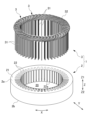
以下、本実施形態のステータの製造方法及びステータ製造装置について図面を参照して詳細に説明する。まず、図1~図5を参照してステータ1について説明する。ステータ1は、例えば、回転電機のステータであり、ステータコア2と、ステータコア2に装着されるセグメントコイル群3と、を含んで構成される。
The stator manufacturing method and stator manufacturing device of this embodiment will be described in detail below with reference to the drawings. First,
ステータコア2は、薄肉のコアプレートが複数積層された積層体からなる円環部21を有する。円環部21は、中心を軸方向に貫通する軸孔20と、軸孔20の周囲に配置され、ステータコア2の軸方向に貫通する複数のスロット22と、を有する。スロット22は、円環部21の周方向に沿って一定の間隔で放射状に配列され、軸孔20に向けて細幅に開口する開口部22aを有する。
The
なお、ステータ1及びステータコア2において、図中の矢印で示すように、周方向は、スロット22が配列されるX方向である。径方向は、放射方向に沿うY方向である。軸方向は、軸孔20を貫通するZ方向である。
In the
セグメントコイル群3は、複数のセグメントコイル30の集合体である。セグメントコイル30は、例えば、断面矩形状の平角線からなる導体を略U字形状に成形することによって構成される。セグメントコイル30は、図2及び図3に示すように、一対の平行な直線部31と、その一対の直線部31の一方端部同士を連結する連結部32と、をそれぞれ有する。本実施形態では、図3に示すように、4本のセグメントコイル30がステータコア2の径方向に積層されて束ねられている。束ねられた4本のセグメントコイル30は、一方の直線部31と他方の直線部31とを、2つのスロット22,22にそれぞれ軸方向に沿って挿入することによって、ステータコア2に装着される。スロット22に挿入された各セグメントコイル30の直線部31,31は、図4に示すように、ステータコア2の挿入側の端面2aとは反対側の端面(一方端面)2bから直立するように突出する。
The
本実施形態では、1つのスロット22に、束ねられた4本のセグメントコイル30の直線部31と、別に束ねられた4本のセグメントコイル30の直線部31とが、ステータコア2の径方向に配列するように挿入される。これによって、スロット22内には、図5に示すように、それぞれ8本の直線部31が径方向に配列される。各スロット22内の8本の直線部31において、ステータコア2の径方向の同一位置に配置される複数の直線部31は、1つの層を形成する。したがって、本実施形態のステータコア2には、径方向内方から外方に向けて1T層~8T層からなる8層構成のセグメントコイル群3が装着される。
In this embodiment, the
ステータコア2の径方向に沿うスロット22の長さは、8本の直線部31をステータコア2の径方向に束ねて配列したときの長さよりも長い。そのため、スロット22内に8本の直線部31が径方向に配列するように挿入されても、スロット22内には直線部31が僅かながらも移動し得る隙間が存在する。なお、ステータコア2のスロット22内にはそれぞれ絶縁部材が挿入されるが、各図において絶縁部材は省略されている。
The length of the
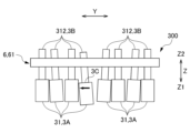
全てのセグメントコイル30がステータコア2の全てのスロット22に挿入された後、ステータコア2の端面2bから突出する直線部31は、図6に示すように、それぞれステータコア2の周方向に折り曲げられてコイルエンド部300を形成する。コイルエンド部300を形成する各直線部31は、ステータコア2の周方向に斜めに折り曲げられた斜行部311と、斜行部311の先端側がステータコア2の軸方向に立ち上がるように折り曲げられた立上がり部312と、をそれぞれ有する。
After all the
各スロット22内の径方向の同一位置に配置される直線部31の斜行部311は、折り曲げ方向が同一方向となるように折り曲げられ、且つ径方向に隣り合う直線部31,31の斜行部311,311は、折り曲げ方向が互いに反対方向となるように折り曲げられる。折り曲げられた同相のセグメントコイル30の直線部31,31の立上がり部312,312同士は、径方向に揃えられ、後述のステータ製造装置4における溶接トーチ42(図7参照)によって溶接されて接合される。
The
なお、セグメントコイル30の全体は、図6に示すように、樹脂製の絶縁被膜3Aによって被覆されるが、セグメントコイル30のそれぞれの直線部31の先端部31aだけは、所定の長さに亘って絶縁被膜3Aが完全に剥離されている。これによって、直線部31の先端部31aに、被膜剥離部3Bがそれぞれ形成されている。立上がり部312は、被膜剥離部3Bのみによって形成されている。
As shown in FIG. 6, the
次に、ステータコア2の端面2bから突出するコイルエンド部300の各立上がり部312を接合することによってステータ1を製造するためのステータ製造装置4の構成について、図7~図12を参照して説明する。
Next, the configuration of the
図7に示すように、ステータ製造装置4は、ステータ1を固定する固定治具41と、TIG(Tungsten Inert Gas)溶接等によって一対の立上がり部312,312を溶接する溶接トーチ42と、スペーサ部材5と、クランプ治具6と、を有する。
As shown in FIG. 7, the
スペーサ部材5は、ステンレス鋼等の金属材によって環状に形成され、ステータコア2の端面2bから突出するコイルエンド部300の層間に、図示しない昇降装置もしくは作業者の手作業によって挿入可能に設けられる。スペーサ部材5は、図8及び図9に示すように、スペーサ本体51と、複数の耳部52と、を有する。
The
スペーサ本体51は、円筒状に形成される。スペーサ本体51の軸方向(Z方向)の長さは、ステータコア2の端面2bから突出するコイルエンド部300の軸方向の突出高さよりもやや短い。したがって、スペーサ部材5がコイルエンド部300の層間に、先端がステータコア2の端面2bに当接するように挿入された際、コイルエンド部300の各立上がり部312は、スペーサ部材5よりも突出するため、後述のクランプ治具6によるクランプ部位が確保される。
The
スペーサ本体51の径方向の板厚は、8本の直線部31が挿入されたスロット22内に残される隙間に相当する厚み以上の厚みを有する。したがって、スペーサ本体51がコイルエンド部300の層間に挿入された際、コイルエンド部300の2つの層は、スロット22の径方向内方と外方とにそれぞれ押し付けられる。図9に示すように、スペーサ本体51の下端部51aは、コイルエンド部300の層間への挿入性を良好にするために、先細り状に形成されている。
The radial thickness of the
耳部52は、スペーサ本体51の上端部に配置され、径方向外側に延びている。本実施形態のスペーサ部材5は、スペーサ本体51の周方向に90度の角度で配置された4つの耳部52を有する。耳部52は、スペーサ部材5が図示しない昇降装置に取り付けられる際の固定部、もしくは作業者によって取り扱われる際の取り扱い部となる部位である。耳部52は、細幅の矩形板状にそれぞれ形成される。詳しくは、耳部52の周方向の幅は、コイルエンド部300の周方向に隣り合う立上がり部312,312間に収まり得る程度の幅を有する。
The
スペーサ部材5は、コイルエンド部300のいずれかの層間に、ステータコア2の端面2b側から挿入される。図10に示すように、本実施形態では、スペーサ部材5は、8層の直線部31からなるコイルエンド部300のうちの4T層と5T層との間に挿入されている。但し、スペーサ部材5は、コイルエンド部300の少なくとも1つの層間に挿入されればよく、2以上の層間にそれぞれ挿入されてもよい。
The
コイルエンド部300の層間に挿入されたスペーサ部材5の各耳部52は、ステータコア2の周方向に隣り合う立上がり部312,312の間に配置される。このとき、スペーサ部材5のスペーサ本体51によって、1T層~4T層はスロット22内の径方向内方に押し付けられ、5T層~8T層はスロット22内の径方向外方に押し付けられる。これによって、スロット22内に挿入されるセグメントコイル30の8層の直線部31は、4層ずつの2つの層に区分され、その2つの層間は、スペーサ部材5のスペーサ本体51によってステータコア2の径方向に拡幅される。
Each
クランプ治具6は、一対のクランプ本体61,61によって構成される。一対のクランプ本体61,61は左右対称構造であるため、図11を参照して1つのクランプ本体61について説明する。クランプ本体61は、ステンレス鋼等の金属材によってステータコア2の径方向に沿って長尺な棒状に形成される。クランプ本体61の長さ方向の両端部には、それぞれ図示しないクランプ駆動装置にボルト63(図13~図15参照)によって取り付けるための取付部62,62が一体に設けられている。
The
クランプ本体61には、他方のクランプ本体61と対向する面61aに、複数のガイド突起611,612を有する。詳しくは、クランプ本体61の面61aには、2つのガイド突起611と1つのガイド突起612とが一体に形成される。1つのガイド突起612は、クランプ本体61の長さ方向の略中央部に配置される。具体的には、ガイド突起612は、コイルエンド部300に挿入されたスペーサ部材5のスペーサ本体51の直上に対応する位置に配置される。ガイド突起611は、クランプ本体61の長さ方向におけるガイド突起612の両側に所定の間隔をおいて1つずつ配置される。
The
ガイド突起611,612は、いずれもステータコア2の径方向に2つの傾斜面を有し、他方のクランプ本体61に向けて先細り状に突出する略三角形状もしくは略台形状に形成される。図12に示すように、ステータコア2の径方向に沿うガイド突起612の幅W1は、2つのガイド突起611,611の幅W2に比べて大きい。取付部62,62の近傍のクランプ本体61の両端部には、2つのガイド突起611,611の外側に所定の間隔をおいて、ガイド突起611が有する一方の傾斜面に対向する傾斜面613,613が形成されている。これによって、図11に示すように、クランプ本体61の面61aにおけるガイド突起611と傾斜面613との間及びガイド突起611とガイド突起612との間に、クランプした一対の立上がり部312,312をそれぞれガイドしつつ収容する収容溝614が形成される。
The guide protrusions 611, 612 each have two inclined surfaces in the radial direction of the
クランプ治具6は、図13に示すように、ガイド突起611,612が互いに対向するように一対のクランプ本体61,61を配置させた状態で、スペーサ部材5が挿入された後のコイルエンド部300の上方から装着される。詳しくは、一対のクランプ本体61,61は、ステータコア2の径方向に沿って配列される8本の直線部31の立上がり部312の端部近傍を、ステータコア2の周方向の両側から挟むことができるように配置される。各クランプ本体61,61の中央のガイド突起612は、コイルエンド部300の4T層と5T層との間に挿入されたスペーサ本体51の略直上に配置される。
As shown in FIG. 13, the
図14に示すように、図示しないクランプ駆動装置の駆動によって一対のクランプ本体61,61が閉じるように動作すると、一対のクランプ本体61,61に挟まれる8本の立上がり部312は、ガイド突起611と傾斜面613との間及びガイド突起611とガイド突起612との間にそれぞれ2本ずつ挟持される。2本ずつの立上がり部312は、ガイド突起611,612のそれぞれの傾斜面と傾斜面613とに案内されて、互いに近接するように径方向に移動し、収容溝614内に収容される。これによって、8本の立上がり部312は、2本ずつの束となってステータコア2の径方向に揃えられる。
As shown in FIG. 14, when the pair of
スペーサ本体51の略直上に配置されるガイド突起612の幅W1は、ガイド突起611の幅W2よりも大きいため、スペーサ本体51を挟んで配置される4T層の直線部31の立上がり部312と5T層の直線部31の立上がり部312とは、ガイド突起612にガイドされ、スロット22内の直線部31と同様に円滑に拡幅される。
The width W1 of the
コイルエンド部300の4T層と8T層との間には、スペーサ部材5のスペーサ本体51が挿入されているため、図15Aに示すように、スロット22内の直線部31は、4T層と5T層との間においてステータコア2の径方向に拡幅され、それぞれスロット22内の内方端及び外方端に押し付けられている。そのため、ステータコア2の径方向の8本の立上がり部312をクランプ治具6の一対のクランプ本体61,61によって周方向から挟み付けた際に、各セグメントコイル30がステータコア2の周方向に引き寄せられても、直線部31がスロット22内でずれることはないため、各立上がり部312の直立姿勢が乱れるおそれはない。
Because the
これに対し、コイルエンド部300にスペーサ部材5を挿入しない場合では、図15Bに示すように、ステータコア2の径方向の8本の立上がり部312をクランプ治具6の一対のクランプ本体61,61によって周方向から挟み付けられてセグメントコイル30がステータコア2の周方向に引き寄せられた際、直線部31がスロット22内でずれ、一部の直線部31にステータコア2の径方向への倒れ込みが発生する場合がある。このとき、絶縁被膜3Aと被膜剥離部3Bとの境界部3Cが、他のセグメントコイル30に角当たりすることによって、絶縁被膜3Aを損傷するおそれがある。
In contrast, when the
クランプ治具6によって8本の立上がり部312を挟み付けた後、溶接トーチ42によって、揃えられた2本の立上がり部312,312が溶接される。これによって、図16に示すように、2本の立上がり部312,312は、先端に溶接部100が形成されて接合される。同様にしてステータコア2の径方向に配列される2本ずつの立上がり部312,312が全て接合されることによって、ステータ1が得られる。
After the eight rising
本実施形態に係るステータ製造方法及びステータ製造装置4によれば、以下の効果を奏する。
The stator manufacturing method and
本実施形態に係るステータの製造方法は、ステータコア2のスロット22内に径方向に複数層に配列されるように挿入されてステータコア2の一方端面2bから突出する複数のセグメントコイル30の直線部31によってコイルエンド部300が形成されるステータ1において、コイルエンド部300におけるスロット22内の径方向に隣接する一対の直線部31,31の端部である立上がり部312,312同士を接合するステータ1の製造方法であって、コイルエンド部300における複数層の直線部31のうちの少なくとも1つの層間を径方向に拡幅させた状態で、ステータコア2の径方向に配列される直線部31の端部近傍を周方向から支持して端部同士を接合する、ステータ1の製造方法である。
The manufacturing method of the stator according to this embodiment is a manufacturing method of the
これによれば、スロット22内の直線部31の少なくとも1つの層間がステータコア2の径方向に拡幅され、それぞれスロット22内の内方端及び外方端に押し付けられるため、直線部31の端部近傍、すなわち立上がり部312の端部近傍が挟み付けられても、直線部31がスロット22内でずれることはなく、各直線部31の立上がり部312の直立姿勢が乱れるおそれはない。そのため、直立姿勢に乱れのない状態のセグメントコイル30の直線部31を接合することができ、ステータ1の精度を向上させることができる。
As a result, at least one layer of the
本実施形態に係るステータ1の製造方法では、少なくとも1つの層間に、ステータコア2の一方端面2b側から環状のスペーサ部材5を挿入することによって、層間を径方向に拡幅させる。
In the manufacturing method of the
これによれば、スロット22内の直線部31をステータコア2の径方向に容易に拡幅でき、直立姿勢の乱れを確実に防止することができる。
This allows the
本実施形態に係るステータ製造装置は、ステータコア2のスロット22内に径方向に複数層に配列されるように挿入されてステータコア2の一方端面2bから突出する複数のセグメントコイル30の直線部31によってコイルエンド部300が形成されるステータ1において、コイルエンド部300におけるスロット22内の径方向に隣接する一対の直線部31,31の端部である立上がり部312,312同士を接合するステータ製造装置4であって、ステータコア2の一方端面2b側から、コイルエンド部300における複数層の直線部31のうちの少なくとも1つの層間に挿入されることによって、層間を径方向に拡幅させる環状のスペーサ部材5と、層間が径方向に拡幅した状態のコイルエンド部300におけるステータコア2の径方向に配列される直線部31の端部近傍、すなわち立上がり部312の端部近傍を周方向から支持するクランプ治具6と、を備える、ステータ製造装置4である。
The stator manufacturing device according to this embodiment is a
これによれば、スロット22内の直線部31の少なくとも1つの層間をステータコア2の径方向に容易に拡幅でき、それぞれスロット22内の内方端及び外方端に押し付けるため、直線部31の端部近傍、すなわち立上がり部312の端部近傍をクランプ治具6によって挟み付けても、直線部31がスロット22内でずれることはなく、各直線部31の立上がり部312の直立姿勢が乱れるおそれはない。そのため、直立姿勢の乱れが確実に防止された状態のセグメントコイル30の直線部31を接合することができ、ステータ1の精度を向上させることができる。
This allows at least one layer of the
本実施形態に係るステータ製造装置4において、クランプ治具6は、直線部31の端部近傍、すなわち立上がり部312の端部近傍を周方向から挟む一対のクランプ本体61,61を有し、一対のクランプ本体61,61は、直線部31の端部近傍、すなわち立上がり部312の端部近傍を周方向から挟むことによって、接合される一対の直線部31の端部である立上がり部312,312同士が互いに近接するように径方向に移動させる複数のガイド突起611,612をそれぞれ備え、複数のガイド突起611,612のうち、スペーサ部材5によって拡幅される層間に対応する部位に配置されるガイド突起612の径方向の幅W1は、他の部位に配置されるガイド突起611の径方向の幅W2よりも大きい。
In the
これによれば、スペーサ部材5を挟んで配置される直線部31,31の立上がり部312,312の間も、ガイド突起612にガイドされて、スロット22内の直線部31,31と同様に円滑に拡幅される。
As a result, the space between the rising
1 ステータ
2 ステータコア
2b 端面(一方端面)
22 スロット
30 セグメントコイル
31 直線部
300 コイルエンド部
4 ステータ製造装置
5 スペーサ部材
6 クランプ治具
61 クランプ本体
611,612 ガイド突起
1
22
Claims (1)
前記ステータコアの前記一方端面側から、前記コイルエンド部における前記複数層の前記直線部のうちの少なくとも1つの層間に挿入されることによって、前記層間を径方向に拡幅させる環状のスペーサ部材と、
前記層間が径方向に拡幅した状態の前記コイルエンド部における前記ステータコアの径方向に配列される前記直線部の前記端部近傍を周方向の両側から挟み付けることによって支持するクランプ治具と、
を備え、
前記クランプ治具は、前記直線部の前記端部近傍を周方向から挟む一対のクランプ本体を有し、
前記一対のクランプ本体は、前記直線部の前記端部近傍を周方向から挟むことによって、接合される一対の前記直線部の前記端部同士が互いに近接するように径方向に移動させる複数のガイド突起をそれぞれ備え、
前記複数のガイド突起のうち、前記スペーサ部材によって拡幅される前記層間に対応する部位に配置される前記ガイド突起の径方向の幅は、他の部位に配置される前記ガイド突起の径方向の幅よりも大きい、ステータ製造装置。 A stator manufacturing device for a stator in which coil end portions are formed by straight portions of a plurality of segment coils that are inserted into slots of a stator core so as to be arranged in multiple layers in the radial direction and protruding from one end face of the stator core, the device joining ends of a pair of straight portions that are adjacent to each other in the radial direction in the slot in the coil end portion,
an annular spacer member that is inserted between at least one of the linear portions of the plurality of layers in the coil end portion from the one end face side of the stator core to radially expand the gap between the layers;
a clamping jig that supports the coil end portion of the stator core by clamping the ends of the linear portions arranged in the radial direction of the stator core in the coil end portion in a state in which the interlayer space is expanded in the radial direction from both sides in the circumferential direction;
Equipped with
The clamp jig has a pair of clamp bodies that circumferentially sandwich the vicinity of the end of the straight portion,
The pair of clamp bodies each include a plurality of guide protrusions that circumferentially sandwich the vicinity of the end of the straight portion, thereby moving the ends of the pair of straight portions to be joined in a radial direction so that they approach each other,
a radial width of the guide protrusions arranged at a portion corresponding to the gap between the layers that is widened by the spacer member is larger than a radial width of the guide protrusions arranged at other portions,
Priority Applications (2)
| Application Number | Priority Date | Filing Date | Title |
|---|---|---|---|
| JP2022156077A JP7586872B2 (en) | 2022-09-29 | 2022-09-29 | Stator manufacturing method and stator manufacturing device |
| CN202310909915.3A CN117791990A (en) | 2022-09-29 | 2023-07-24 | Stator manufacturing method and stator manufacturing device |
Applications Claiming Priority (1)
| Application Number | Priority Date | Filing Date | Title |
|---|---|---|---|
| JP2022156077A JP7586872B2 (en) | 2022-09-29 | 2022-09-29 | Stator manufacturing method and stator manufacturing device |
Publications (2)
| Publication Number | Publication Date |
|---|---|
| JP2024049689A JP2024049689A (en) | 2024-04-10 |
| JP7586872B2 true JP7586872B2 (en) | 2024-11-19 |
Family
ID=90384162
Family Applications (1)
| Application Number | Title | Priority Date | Filing Date |
|---|---|---|---|
| JP2022156077A Active JP7586872B2 (en) | 2022-09-29 | 2022-09-29 | Stator manufacturing method and stator manufacturing device |
Country Status (2)
| Country | Link |
|---|---|
| JP (1) | JP7586872B2 (en) |
| CN (1) | CN117791990A (en) |
Families Citing this family (1)
| Publication number | Priority date | Publication date | Assignee | Title |
|---|---|---|---|---|
| CN120862050B (en) * | 2025-09-29 | 2025-12-16 | 深圳市金岷江智能装备有限公司 | Welding clamping device and welding equipment |
Citations (3)
| Publication number | Priority date | Publication date | Assignee | Title |
|---|---|---|---|---|
| JP2003219614A (en) | 2002-01-21 | 2003-07-31 | Mitsubishi Electric Corp | Winding joining method for rotating electrical machines |
| WO2017159865A1 (en) | 2016-03-17 | 2017-09-21 | 本田技研工業株式会社 | Clamp jig, stator manufacturing device, and method for manufacturing stator |
| JP2022074406A (en) | 2020-11-04 | 2022-05-18 | トヨタ自動車株式会社 | Stator manufacturing device |
-
2022
- 2022-09-29 JP JP2022156077A patent/JP7586872B2/en active Active
-
2023
- 2023-07-24 CN CN202310909915.3A patent/CN117791990A/en active Pending
Patent Citations (3)
| Publication number | Priority date | Publication date | Assignee | Title |
|---|---|---|---|---|
| JP2003219614A (en) | 2002-01-21 | 2003-07-31 | Mitsubishi Electric Corp | Winding joining method for rotating electrical machines |
| WO2017159865A1 (en) | 2016-03-17 | 2017-09-21 | 本田技研工業株式会社 | Clamp jig, stator manufacturing device, and method for manufacturing stator |
| JP2022074406A (en) | 2020-11-04 | 2022-05-18 | トヨタ自動車株式会社 | Stator manufacturing device |
Also Published As
| Publication number | Publication date |
|---|---|
| JP2024049689A (en) | 2024-04-10 |
| CN117791990A (en) | 2024-03-29 |
Similar Documents
| Publication | Publication Date | Title |
|---|---|---|
| EP1328059B1 (en) | Rotary electric machine and method for connecting stator conductors | |
| JP3279279B2 (en) | Iron core equipment | |
| US6515394B2 (en) | Stacked coil assembly for a stator | |
| US11502586B2 (en) | Stator of a motor | |
| CN210693605U (en) | Stator assembly for hairpin winding motors | |
| JP6663942B2 (en) | Rotating electric machine stator | |
| KR20020077041A (en) | Stator and stator core for a dynamoelectric machine and a method for manufacture thereof | |
| JP6483079B2 (en) | Electrical conductor joining method | |
| JP2013165615A (en) | Positioning device of segment coil | |
| JP2015035922A (en) | Coil joining method of rotating electrical machine | |
| JP7586872B2 (en) | Stator manufacturing method and stator manufacturing device | |
| JP2020114062A (en) | Rotary electric machine stator and production method therefor | |
| JP4410730B2 (en) | Rotating electric machine stator, rotating electric machine, and method of manufacturing rotating electric machine stator | |
| JP7503353B2 (en) | Segment coil welding device and method of manufacturing a stator for a rotating electric machine | |
| JP3316762B1 (en) | Manufacturing method of iron core device | |
| JP6486545B2 (en) | Stator for rotating electrical machine, rotating electrical machine using the same, and method for manufacturing stator for rotating electrical machine | |
| JP7646681B2 (en) | Welding jig and manufacturing method for rotating electric machine | |
| JP4443286B2 (en) | Rotating motor stator, rotating motor coil mounting method, coil winding machine | |
| JP2006025544A (en) | Winding joining device for rotating electrical machines | |
| JP5712820B2 (en) | Jig for rotating electrical machine coil | |
| JP5343905B2 (en) | Welding and holding device for winding coils of rotating electrical machines | |
| JP7474816B2 (en) | Stator manufacturing apparatus and method | |
| CN217669111U (en) | Assembling tool for block type stator | |
| JP2006157993A (en) | Segment type stator and manufacturing method thereof | |
| CN100399672C (en) | Manufacturing method of iron core of rotating electric machine |
Legal Events
| Date | Code | Title | Description |
|---|---|---|---|
| A621 | Written request for application examination |
Free format text: JAPANESE INTERMEDIATE CODE: A621 Effective date: 20230526 |
|
| A131 | Notification of reasons for refusal |
Free format text: JAPANESE INTERMEDIATE CODE: A131 Effective date: 20240618 |
|
| A521 | Request for written amendment filed |
Free format text: JAPANESE INTERMEDIATE CODE: A523 Effective date: 20240709 |
|
| A131 | Notification of reasons for refusal |
Free format text: JAPANESE INTERMEDIATE CODE: A131 Effective date: 20240910 |
|
| A521 | Request for written amendment filed |
Free format text: JAPANESE INTERMEDIATE CODE: A523 Effective date: 20240926 |
|
| TRDD | Decision of grant or rejection written | ||
| A01 | Written decision to grant a patent or to grant a registration (utility model) |
Free format text: JAPANESE INTERMEDIATE CODE: A01 Effective date: 20241105 |
|
| A61 | First payment of annual fees (during grant procedure) |
Free format text: JAPANESE INTERMEDIATE CODE: A61 Effective date: 20241107 |
|
| R150 | Certificate of patent or registration of utility model |
Ref document number: 7586872 Country of ref document: JP Free format text: JAPANESE INTERMEDIATE CODE: R150 |