JP7586849B2 - Operating device for hydraulic operating system - Google Patents
Operating device for hydraulic operating system Download PDFInfo
- Publication number
- JP7586849B2 JP7586849B2 JP2022055982A JP2022055982A JP7586849B2 JP 7586849 B2 JP7586849 B2 JP 7586849B2 JP 2022055982 A JP2022055982 A JP 2022055982A JP 2022055982 A JP2022055982 A JP 2022055982A JP 7586849 B2 JP7586849 B2 JP 7586849B2
- Authority
- JP
- Japan
- Prior art keywords
- piston
- housing
- operating device
- unit
- control unit
- Prior art date
- Legal status (The legal status is an assumption and is not a legal conclusion. Google has not performed a legal analysis and makes no representation as to the accuracy of the status listed.)
- Active
Links
Images


Classifications
-
- B—PERFORMING OPERATIONS; TRANSPORTING
- B60—VEHICLES IN GENERAL
- B60T—VEHICLE BRAKE CONTROL SYSTEMS OR PARTS THEREOF; BRAKE CONTROL SYSTEMS OR PARTS THEREOF, IN GENERAL; ARRANGEMENT OF BRAKING ELEMENTS ON VEHICLES IN GENERAL; PORTABLE DEVICES FOR PREVENTING UNWANTED MOVEMENT OF VEHICLES; VEHICLE MODIFICATIONS TO FACILITATE COOLING OF BRAKES
- B60T13/00—Transmitting braking action from initiating means to ultimate brake actuator with power assistance or drive; Brake systems incorporating such transmitting means, e.g. air-pressure brake systems
- B60T13/10—Transmitting braking action from initiating means to ultimate brake actuator with power assistance or drive; Brake systems incorporating such transmitting means, e.g. air-pressure brake systems with fluid assistance, drive, or release
- B60T13/12—Transmitting braking action from initiating means to ultimate brake actuator with power assistance or drive; Brake systems incorporating such transmitting means, e.g. air-pressure brake systems with fluid assistance, drive, or release the fluid being liquid
- B60T13/14—Transmitting braking action from initiating means to ultimate brake actuator with power assistance or drive; Brake systems incorporating such transmitting means, e.g. air-pressure brake systems with fluid assistance, drive, or release the fluid being liquid using accumulators or reservoirs fed by pumps
- B60T13/142—Systems with master cylinder
-
- B—PERFORMING OPERATIONS; TRANSPORTING
- B60—VEHICLES IN GENERAL
- B60T—VEHICLE BRAKE CONTROL SYSTEMS OR PARTS THEREOF; BRAKE CONTROL SYSTEMS OR PARTS THEREOF, IN GENERAL; ARRANGEMENT OF BRAKING ELEMENTS ON VEHICLES IN GENERAL; PORTABLE DEVICES FOR PREVENTING UNWANTED MOVEMENT OF VEHICLES; VEHICLE MODIFICATIONS TO FACILITATE COOLING OF BRAKES
- B60T17/00—Component parts, details, or accessories of power brake systems not covered by groups B60T8/00, B60T13/00 or B60T15/00, or presenting other characteristic features
- B60T17/02—Arrangements of pumps or compressors, or control devices therefor
-
- B—PERFORMING OPERATIONS; TRANSPORTING
- B60—VEHICLES IN GENERAL
- B60T—VEHICLE BRAKE CONTROL SYSTEMS OR PARTS THEREOF; BRAKE CONTROL SYSTEMS OR PARTS THEREOF, IN GENERAL; ARRANGEMENT OF BRAKING ELEMENTS ON VEHICLES IN GENERAL; PORTABLE DEVICES FOR PREVENTING UNWANTED MOVEMENT OF VEHICLES; VEHICLE MODIFICATIONS TO FACILITATE COOLING OF BRAKES
- B60T7/00—Brake-action initiating means
- B60T7/02—Brake-action initiating means for personal initiation
- B60T7/04—Brake-action initiating means for personal initiation foot actuated
- B60T7/042—Brake-action initiating means for personal initiation foot actuated by electrical means, e.g. using travel or force sensors
-
- B—PERFORMING OPERATIONS; TRANSPORTING
- B60—VEHICLES IN GENERAL
- B60T—VEHICLE BRAKE CONTROL SYSTEMS OR PARTS THEREOF; BRAKE CONTROL SYSTEMS OR PARTS THEREOF, IN GENERAL; ARRANGEMENT OF BRAKING ELEMENTS ON VEHICLES IN GENERAL; PORTABLE DEVICES FOR PREVENTING UNWANTED MOVEMENT OF VEHICLES; VEHICLE MODIFICATIONS TO FACILITATE COOLING OF BRAKES
- B60T8/00—Arrangements for adjusting wheel-braking force to meet varying vehicular or ground-surface conditions, e.g. limiting or varying distribution of braking force
- B60T8/32—Arrangements for adjusting wheel-braking force to meet varying vehicular or ground-surface conditions, e.g. limiting or varying distribution of braking force responsive to a speed condition, e.g. acceleration or deceleration
- B60T8/34—Arrangements for adjusting wheel-braking force to meet varying vehicular or ground-surface conditions, e.g. limiting or varying distribution of braking force responsive to a speed condition, e.g. acceleration or deceleration having a fluid pressure regulator responsive to a speed condition
- B60T8/36—Arrangements for adjusting wheel-braking force to meet varying vehicular or ground-surface conditions, e.g. limiting or varying distribution of braking force responsive to a speed condition, e.g. acceleration or deceleration having a fluid pressure regulator responsive to a speed condition including a pilot valve responding to an electromagnetic force
- B60T8/3615—Electromagnetic valves specially adapted for anti-lock brake and traction control systems
- B60T8/3675—Electromagnetic valves specially adapted for anti-lock brake and traction control systems integrated in modulator units
- B60T8/368—Electromagnetic valves specially adapted for anti-lock brake and traction control systems integrated in modulator units combined with other mechanical components, e.g. pump units, master cylinders
-
- B—PERFORMING OPERATIONS; TRANSPORTING
- B60—VEHICLES IN GENERAL
- B60T—VEHICLE BRAKE CONTROL SYSTEMS OR PARTS THEREOF; BRAKE CONTROL SYSTEMS OR PARTS THEREOF, IN GENERAL; ARRANGEMENT OF BRAKING ELEMENTS ON VEHICLES IN GENERAL; PORTABLE DEVICES FOR PREVENTING UNWANTED MOVEMENT OF VEHICLES; VEHICLE MODIFICATIONS TO FACILITATE COOLING OF BRAKES
- B60T2220/00—Monitoring, detecting driver behaviour; Signalling thereof; Counteracting thereof
- B60T2220/04—Pedal travel sensor, stroke sensor; Sensing brake request
-
- B—PERFORMING OPERATIONS; TRANSPORTING
- B60—VEHICLES IN GENERAL
- B60Y—INDEXING SCHEME RELATING TO ASPECTS CROSS-CUTTING VEHICLE TECHNOLOGY
- B60Y2400/00—Special features of vehicle units
- B60Y2400/42—Clutches or brakes
-
- F—MECHANICAL ENGINEERING; LIGHTING; HEATING; WEAPONS; BLASTING
- F16—ENGINEERING ELEMENTS AND UNITS; GENERAL MEASURES FOR PRODUCING AND MAINTAINING EFFECTIVE FUNCTIONING OF MACHINES OR INSTALLATIONS; THERMAL INSULATION IN GENERAL
- F16D—COUPLINGS FOR TRANSMITTING ROTATION; CLUTCHES; BRAKES
- F16D2121/00—Type of actuator operation force
- F16D2121/02—Fluid pressure
- F16D2121/04—Fluid pressure acting on a piston-type actuator, e.g. for liquid pressure
-
- F—MECHANICAL ENGINEERING; LIGHTING; HEATING; WEAPONS; BLASTING
- F16—ENGINEERING ELEMENTS AND UNITS; GENERAL MEASURES FOR PRODUCING AND MAINTAINING EFFECTIVE FUNCTIONING OF MACHINES OR INSTALLATIONS; THERMAL INSULATION IN GENERAL
- F16D—COUPLINGS FOR TRANSMITTING ROTATION; CLUTCHES; BRAKES
- F16D2121/00—Type of actuator operation force
- F16D2121/18—Electric or magnetic
- F16D2121/24—Electric or magnetic using motors
Landscapes
- Engineering & Computer Science (AREA)
- Transportation (AREA)
- Mechanical Engineering (AREA)
- Physics & Mathematics (AREA)
- Electromagnetism (AREA)
- Fluid Mechanics (AREA)
- Regulating Braking Force (AREA)
- Braking Systems And Boosters (AREA)
- Braking Elements And Transmission Devices (AREA)
- Hydraulic Clutches, Magnetic Clutches, Fluid Clutches, And Fluid Joints (AREA)
- Transmission Devices (AREA)
Description
本発明は、特許請求項1の上位概念部に記載の液圧式の操作システム用の操作装置、特に自動車ブレーキまたは電化されたクラッチアクチュエータおよびギヤアクチュエータ用の操作装置に関する。
The present invention relates to an actuating device for a hydraulic actuating system, in particular for an actuating device for a motor vehicle brake or electrified clutch actuator and gear actuator, as described in the generic part of
従来技術
機器の組み込み、特にエンジンルームまたは機器室内への機器の組み込みは、自動車製造元(OEM)の多数の新しいシステムに鑑み、逼迫した組み込みスペースの理由からますます大きな問題に直面している。一部において、例えばABS用機器は、特に前輪駆動および横置きエンジンの場合、エンジンの後方に配置される。このことは、ABS用機器を交換する際には、エンジンが取り外されねばならないという結果を伴う。
PRIOR ART The installation of equipment, especially in the engine or equipment compartment, is facing increasing problems due to the tight installation space in view of the many new systems of the OEMs. In some cases, for example, the ABS equipment is located behind the engine, especially in the case of front-wheel drive and transverse engines. This has the consequence that the engine must be removed when replacing the ABS equipment.
それゆえ、既存の機器を小型化または新たにできる限りコンパクトに構成すべきというOEMの要求が存在する。右ハンドルと左ハンドルとが存在するという事情もあり、このことは、ブレーキ機器において、いわゆるパッケージングは同じであることが望ましいという結果を伴う。 Therefore, there is a demand from OEMs to miniaturize existing equipment or to design new equipment as compact as possible. Given the existence of right-hand drive and left-hand drive vehicles, this has the consequence that the so-called packaging of brake equipment is desirably the same.
多くの機器は、電気的な機能およびセンサを有しており、これらは、往々にして複数のコネクタを必要とし、このことは、特に組み立てに手間を要する。 Many devices have electrical functions and sensors that often require multiple connectors, which makes assembly particularly tedious.
さらに衝突安全性への要求は、ますます高まっており、このことは、機器室内のシステムの組み込み長さが、特にシステムが前壁に取り付けられていて、隣接する機器または制御器がこの組み込みユニットに対して取着されているとき、できる限り短く細身であるべきという結果を伴う。 Furthermore, the demands on crash safety are ever increasing, which has the consequence that the installation length of the system in the equipment room should be as short and slim as possible, especially when the system is mounted on the front wall and adjacent equipment or controls are attached to this installation unit.
公知であるように、ブレーキシステムにおいて、今日一般的であるいわゆる「3ボックス解決手段(3-Box-Loesung)」、すなわち、制動倍力装置(Bremskraftverstaerker)、ABS/ESP用機器および真空ポンプがそれぞれ異なる構成ユニットを形成しており、これらの構成ユニットが特に空間的にも隔絶されていることができる解決手段から、統合型の「1ボックス解決手段(1-Box-Loesung)」、すなわち、すべてのコンポーネント、例えば圧力供給部、液圧式の(弁)ユニット(HCU)、制御ユニット(ECU)および主シリンダ(Hauptzylinder)が1つの構成ユニット内に統合されている解決手段に切り換わる強い傾向が存在している。DE102012213216には、例えばこのようなコンパクトな「1ボックスブレーキシステム」が記載されている。主たる特徴は、電気モータの軸線が、第1のシリンダピストンユニットの長手方向軸線に対して垂直であることである。 As is known, there is a strong tendency in brake systems to switch from the so-called "three-box solutions" that are common today, in which the brake booster, the ABS/ESP device and the vacuum pump form different components, which can be separated in particular spatially, to integrated "one-box solutions", in which all components, such as the pressure supply, the hydraulic (valve) unit (HCU), the control unit (ECU) and the main cylinder, are integrated in one component. DE 10 2012 213 216 describes, for example, such a compact "one-box brake system". The main feature is that the axis of the electric motor is perpendicular to the longitudinal axis of the first cylinder-piston unit.
1980年代の中頃、Tevesは、Mark 2でもって、この特徴を有する半統合型の解決手段を、しかし、ポンプを有する電気モータの軸線が操作軸線に対して平行に配置された変化態様としても提供していた。注目すべきは、紹介する本発明とは異なり、モータ、圧力供給部およびECUが1つのハウジングユニット内に統合されていないことである。ここでは、モータは、ポンプとともに取り付けられ、チューブ線路により弁ブロック(HCU)とシリンダピストンユニットとからなるハウジングに接続されていた。極めて細身で短い構成ユニットという目標設定は、まだ達成されていなかった。 In the mid-1980s, Teves offered a semi-integrated solution with this feature in the Mark 2, but also in a variant in which the axis of the electric motor with the pump was arranged parallel to the operating axis. It should be noted that, unlike the present invention, the motor, pressure supply and ECU were not integrated in one housing unit. Here, the motor was mounted together with the pump and connected by tube lines to the housing consisting of the valve block (HCU) and the cylinder-piston unit. The goal of an extremely slender and short structural unit had not yet been achieved.
電気式の駆動モータ用のセンサとして、DE102011017436には、モータターゲットの歯車駆動が記載されている。ここでは、センサ要素は、センサモジュール内に配置されており、センサモジュールは、差し込み接続を介してシステム回路板に接続されている。付加的に、冗長なペダルストロークセンサと、ブレーキ液体容器内の充填レベルを監視するセンサとが必要とされる。 As a sensor for an electric drive motor, DE 10 2011 017 436 describes a gear drive of a motor target. Here, the sensor element is arranged in a sensor module, which is connected to the system circuit board via a plug-in connection. In addition, a redundant pedal stroke sensor and a sensor for monitoring the filling level in the brake fluid container are required.
DE102012213216に記載のブレーキ設備の場合、車両操縦者により操作される第1のシリンダ-ピストン-アッセンブリと、圧力提供装置と、弁装置とが、同じハウジング内に配置されており、圧力提供装置の電気モータの軸線は、第1のシリンダ-ピストン-アッセンブリの長手方向軸線に対して略垂直に配置されている。この解決手段により、既にある程度のコンパクト性が得られるように努められてはいるものの、さらなる改良の余地がある。特にDE102012213216は、従来慣用の真空式倍力装置の円形の輪郭の空間的な境界条件に合わせて設計されており、車両内の全体的なパッケージング最適化は考慮していない。最適なパッケージングのためには、矩形の構造形態が、円形の輪郭より好ましい。また、特に様々な組み付け状況への適応性、例えばエンジンルーム内での、特にバルクヘッドに組み付けられる電気式制動倍力装置(Elektrischer Bremskraftverstaerker)および統合型のABSを有する電気式制動倍力装置のための組み付け(いわゆる「フロントボルト固定型(front bolted)」)についての適応性等、改良すべき点も残されている。
In the case of the brake system according to
さらなる要求としては:
-短く細身の構造形態、
-液圧式の線路、特にホイールブレーキへのブレーキ線路を組み付けるための良好な接近性、
-コネクタ、特に主線路ハーネスのコネクタのための良好な接近性と、自動車分配器ボックス(セントラルエレクトリックシステム)への短いケーブル長さ、
-最終組み立て状態(真空状態)のみならず、保守中も良好な空気抜き性(ペダル操作による空気抜き)、
-コネクタからモータ制御部の電力部へのパワー線路の短い線路程、
-電力部(出力段、MOSFETおよびドライバ)の良好な冷却および熱導出、
-駆動部および電磁弁のノイズ、バルクヘッドへの固体伝播音伝達の減少、
-THZからの短い孔、HCUへの圧力遅延、
がある。
Further requirements include:
- Short and slender structural form,
- good accessibility for mounting the hydraulic lines, in particular the brake lines to the wheel brakes;
- good accessibility for connectors, especially for the mainline harness connectors, and short cable lengths to the vehicle distribution box (central electric system);
- Good air release during maintenance (air release by pedal operation) as well as in the final assembly state (vacuum state),
- short lengths of power lines from the connector to the power section of the motor control,
- good cooling and heat dissipation of the power section (output stage, MOSFETs and drivers),
- Reduction of actuator and solenoid valve noise, and structure-borne sound transmission to bulkheads;
- Short hole from THZ, pressure delay to HCU,
There is.
発明の課題
それゆえ本発明の課題は、例えば柔軟に様々な車両あるいは組み込み状況に適した、できる限りコンパクトかつ重量およびコストの面で有利な液圧式のコンポーネント用の操作装置、特に自動車ブレーキ、液圧式のクラッチまたはギヤアクチュエータ用の操作装置を提供することである。
Object of the Invention It is therefore an object of the present invention to provide an actuating device for hydraulic components, in particular an actuating device for automobile brakes, hydraulic clutches or gear actuators, which is as compact as possible and advantageous in terms of weight and cost, for example flexibly adapted to various vehicle or installation situations.
課題の解決手段
本発明の課題は、特許請求項1の特徴を備える操作装置により解決される。
Solution to the problem The problem according to the invention is solved by an operating device having the features of
本発明に係る操作装置は、有利には、コンパクトかつ低コストであり、軽量であり、しかも、様々な車両あるいは組み込み状況に対して柔軟であるという点で優れている。車両ブレーキ用の操作装置として使用したとき、本発明に係る操作装置は、有利には、以下の要求を充足し、以下の利点を有している:
-短く細身の構造形態と、特に矩形の基本形状および良好なコネクタポジショニングにより、車両内の他のコンポーネントにとって最適に利用可能な幾何学形状;
-左ハンドル(LL)および右ハンドル(RL)のために大幅に対称化した構成;
-液圧式および電気式の接続部の組み付けのための良好な接近性;
-車両の前壁(バルクヘッド)への、エンジン側から(フロントボルト固定型)も、フットスペース側からも可能な取り付け;
-とりわけ短い接続孔によるできる限り低いコストおよび重量;
-様々な拡張段階、例えば自律走行のためのモジュール構造;
-エラーに対する高い安全性;
-良好な空気抜き性;
-良好な冷却と、PCBから、高い熱容量を有するハウジングユニットへの熱導出;
-低い固体伝播音伝達によるパッセンジャルーム内のノイズレベルの低減;
-組み付け時および空気抜き時の良好な取り扱い性;
-車両内のすべてのコンポーネントの全体的なパッケージングに合わせて最適化された構成スペース。
The actuating device according to the invention is advantageously compact, low-cost, lightweight and flexible for different vehicles or installation situations. When used as an actuating device for vehicle brakes, the actuating device according to the invention advantageously meets the following requirements and has the following advantages:
- A short and slender construction form and an optimally accessible geometry for other components in the vehicle, especially due to the rectangular basic shape and good connector positioning;
- Highly symmetrical configuration for left-hand drive (LL) and right-hand drive (RL);
- good accessibility for the assembly of hydraulic and electrical connections;
- Mounting to the front wall (bulkhead) of the vehicle, either from the engine side (front bolt-on) or from the footwell side;
- lowest possible costs and weight due to particularly short connection holes;
- Modular structure for different expansion stages, e.g. autonomous driving;
- high security against errors;
- good air release;
- good cooling and heat dissipation from the PCB to the housing unit with high thermal mass;
- Reduced noise levels in the passenger compartment due to low structure-borne sound transmission;
- good handling during assembly and evacuation;
- Optimized configuration space for overall packaging of all components within the vehicle.
本発明は、有利には、ピストン-シリンダ-ユニットの軸線と、圧力供給装置のピストンポンプあるいはダブルアクションピストンポンプの軸線とが、互いに平行に、かつ鉛直方向で互いに間隔を置いて配置されていることと、ピストン-シリンダ-ユニットおよび圧力供給ユニットが、第1のハウジング内に配置されており、駆動部が、第1のハウジングに取り付けられており、ピストン-シリンダ-ユニットの軸線の下方に配置されていることとを特徴とする。その際、駆動部と第1のハウジングとの間には、さらに、特に遮音性の中間ハウジングまたは要素が配置されていてもよい。操作装置が車両内で車両のホイールブレーキの圧力制御のために使用される場合、操作装置は、鉛直線に対して5°ないし30°の角度φの分だけ傾倒されてエンジンルーム内に配置されていてもよい。本発明に係る操作装置のこの有利な構成により、特にスリムな構造形式が得られるので、本発明に係る操作機構は、極めて短く構成され、かつ省スペースに例えばエンジンルーム内に配置される。これにより、車両内で本発明に係る操作機構は、有利には、左ハンドル車内での使用にも、右ハンドル車内での使用にも、使用可能である。 The invention is advantageously characterized in that the axis of the piston-cylinder unit and the axis of the piston pump or double-acting piston pump of the pressure supply device are arranged parallel to one another and spaced apart from one another in the vertical direction, and that the piston-cylinder unit and the pressure supply unit are arranged in a first housing, and the drive is attached to the first housing and arranged below the axis of the piston-cylinder unit. In this case, an intermediate housing or element, which is particularly sound-insulating, may also be arranged between the drive and the first housing. If the actuating device is used in a vehicle for controlling the pressure of the wheel brakes of the vehicle, the actuating device may be arranged in the engine compartment tilted by an angle φ of 5° to 30° to the vertical. This advantageous configuration of the actuating device according to the invention results in a particularly slim construction, so that the actuating mechanism according to the invention is designed to be very short and is arranged in a space-saving manner, for example in the engine compartment. As a result, the actuating mechanism according to the invention can be advantageously used in a vehicle both in left-hand drive vehicles and in right-hand drive vehicles.
少数の電磁弁、圧力トランスデューサを有する液圧式のシステム(例えばクラッチアクチュエータおよびギヤアクチュエータ)において、あるいは主ブレーキシリンダを有しない構成(例えば主ブレーキシリンダなしのブレーキ-バイ-ワイヤ式の液圧システム、少数の電磁弁を有する液圧システム)において、極度に細身の構造形態を実現するという意味で、電磁弁および圧力トランスデューサを含むハウジング部分(GH2)も、圧力供給器装置を有する第1のハウジング部分に対して互いに平行に、かつ鉛直方向で互いに間隔を置いて配置され得る。その際、電磁弁は、電磁弁の磁石コイルを含むECUの被せ嵌めにより直接的に接点接続されるように、圧力供給器装置の軸線に対して垂直に配置されている。このことは、モータの回転角トランスデューサがECUに対して僅かな間隔を置いており、より簡単に接点接続され得るという利点も有している。 In hydraulic systems with a small number of solenoid valves, pressure transducers (e.g. clutch actuators and gear actuators) or in configurations without a main brake cylinder (e.g. brake-by-wire hydraulic systems without a main brake cylinder, hydraulic systems with a small number of solenoid valves), the housing part (GH2) containing the solenoid valves and pressure transducers can also be arranged parallel to the first housing part with the pressure supplier device and spaced apart from each other in the vertical direction, in order to achieve an extremely slender construction. In this case, the solenoid valves are arranged perpendicular to the axis of the pressure supplier device so that they are directly contact-connected by the ECU, which includes the magnet coils of the solenoid valves, by being fitted over them. This also has the advantage that the rotation angle transducer of the motor is spaced apart from the ECU by a small distance and can be contact-connected more easily.
弁装置は、固有の第2のハウジング内に配置されているか、またはともに第1のハウジング内に配置されているか、または第1のハウジングの構成部材であることができる。 The valve device may be located in a separate second housing, or may be located together in the first housing, or may be a component of the first housing.
開ループ・閉ループ制御ユニットの回路板との間の電気的な接続は、有利には、差し込み可能に構成されていることができるので、開ループ・閉ループ制御ユニットを駆動モータおよび弁装置に載置したとき、駆動モータも、センサシステムも、電磁弁も、直接的に開ループ・閉ループ制御ユニットに接点接続される。これにより、有利には、付加的な配線ステップが省略される。 The electrical connection between the circuit board of the open-loop/closed-loop control unit can advantageously be configured to be pluggable, so that when the open-loop/closed-loop control unit is mounted on the drive motor and valve device, the drive motor, the sensor system and the solenoid valve are directly contact-connected to the open-loop/closed-loop control unit. This advantageously avoids additional wiring steps.
さらに、本発明に係る操作装置は、大半のまたはすべての液圧コンポーネント、特に電磁弁、圧力ピストン、主ブレーキシリンダが、1つの液圧ブロック内に配置されているように形成されていてもよい。その際、液圧ブロックは、1つの部分または2つの部分から形成されていることができる。2つの部分からなる構成の場合、第1のハウジングと第2のハウジングとは、有利には、形状結合式または力結合式に互いに結合されている。両ハウジング間に「液圧式の回路板(hydraulische Leiterplatte)」を配置することも可能である。液圧式の回路板は、液圧式の接続、特に液圧式のコンポーネント、THZ、圧力供給部、電磁弁および圧力トランスデューサの液圧式の接続を可能にするあるいは実現する。これにより、有利には、弁プレートの厚さならびに接続孔および閉塞栓の数を減じることができる。付加的に、両ハウジング間の良好な熱の移行が生じると、有利である。 Furthermore, the actuating device according to the invention can be designed in such a way that most or all of the hydraulic components, in particular the solenoid valve, the pressure piston, the main brake cylinder, are arranged in a hydraulic block. In this case, the hydraulic block can be designed in one part or in two parts. In the case of a two-part design, the first housing and the second housing are preferably connected to each other in a form-locking or force-locking manner. It is also possible to arrange a "hydraulic circuit board" between the two housings. The hydraulic circuit board enables or realizes the hydraulic connection, in particular the hydraulic connection of the hydraulic components, the THZ, the pressure supply, the solenoid valve and the pressure transducer. This advantageously makes it possible to reduce the thickness of the valve plate as well as the number of connection holes and plugs. In addition, it is advantageous if good heat transfer between the two housings occurs.
本発明の有利な一構成は、弁装置の一方の側に、圧力供給装置およびピストン-シリンダ-ユニットが配置され、弁装置の反対側に、電子式の開ループ・閉ループ制御ユニットが配置されているときに得られる。このサンドイッチ状のアッセンブリは、有利には、小型で省スペースのアッセンブリを実現し、電子式の開ループ・閉ループ制御ユニットおよび弁装置のハウジングは、高さおよび奥行きより大幅に小さい幅を有している。 An advantageous configuration of the invention is obtained when the pressure supply device and the piston-cylinder unit are arranged on one side of the valve device and the electronic open-loop/closed-loop control unit is arranged on the opposite side of the valve device. This sandwich-like assembly advantageously results in a compact and space-saving assembly, where the housing of the electronic open-loop/closed-loop control unit and the valve device has a width that is significantly smaller than its height and depth.
前述の実施の形態は、電子式の開ループ・閉ループ制御ユニットと、弁装置と、圧力供給装置およびピストン-シリンダ-ユニットを重ね合わせに配置したアッセンブリとからなる配列の端面側に、モータが配置されていることで補われてもよい。さらに電子式の開ループ・閉ループ制御ユニットのハウジングの一部分が、弁装置および/または第1のハウジングの上方に配置されていてもよい。また、その際、有利には、貯蔵容器が、ピストン-シリンダ-ユニットの上方または電子式の開ループ・閉ループ制御ユニットのハウジングの上述の部分の上方に配置されていることも可能である。設けねばならない液圧式の連通線路をできる限り少なくすべく、貯蔵容器は、貯蔵容器の一領域が、第1のハウジングの側方を下向きに延在し、この領域が、ハウジングの入口通路および出口通路に接続する接続部を有しているように形成されていてもよい。 The above-mentioned embodiment may be supplemented by the arrangement of the motor on the end side of the arrangement of the electronic open-loop/closed-loop control unit, the valve device, the pressure supply device and the piston-cylinder unit arranged one on top of the other. Furthermore, a part of the housing of the electronic open-loop/closed-loop control unit may be arranged above the valve device and/or the first housing. In this case, it is also advantageously possible for the storage container to be arranged above the piston-cylinder unit or above the above-mentioned part of the housing of the electronic open-loop/closed-loop control unit. In order to minimize the number of hydraulic communication lines that need to be provided, the storage container may be designed in such a way that a region of the storage container extends downwards on the side of the first housing and has connections to the inlet and outlet passages of the housing.
別の可能な一実施の形態において、有利には、弁装置は、ピストン-シリンダ-ユニットの軸線の上方に配置されている。これにより、同じく、本発明に係る操作装置のすべてのコンポーネントの極めて小さく良好な配置が生じる。この構成の場合、電子式の開ループ・閉ループ制御ユニットが、横断面図で見てL字形またはU字形に形成されており、第1のハウジングの2面または3面に当接していると、特に有利である。特に電子式の開ループ・閉ループ制御ユニットのU字形の形成は、コンポーネント間の極めて簡単な電気的な接続と良好な熱導出との点で優れている。その際、開ループ・閉ループ制御ユニットのハウジングは、第1のハウジングを下方より囲繞し、第1のハウジングの側方を上方に延在する両脚片領域は、上方に弁装置まで延在している。これにより、弁装置と開ループ・閉ループ制御ユニットとの間の、間に何も介しない結合も可能である。而して電磁弁の駆動コイルは、開ループ・閉ループ制御ユニット内に格納され、電磁弁の可動子その他の液圧式のコンポーネントは、弁装置内に格納されていることができる。 In another possible embodiment, the valve device is preferably arranged above the axis of the piston-cylinder unit. This also results in a very compact and good arrangement of all components of the actuation device according to the invention. In this configuration, it is particularly advantageous if the electronic open-loop/closed-loop control unit is L- or U-shaped in cross section and abuts on two or three sides of the first housing. The U-shaped design of the electronic open-loop/closed-loop control unit in particular is advantageous in terms of a very simple electrical connection between the components and good heat dissipation. The housing of the open-loop/closed-loop control unit then surrounds the first housing from below, and the two leg areas that run up the sides of the first housing run up to the valve device. This also makes it possible to connect the valve device and the open-loop/closed-loop control unit without any intermediate parts. The drive coil of the solenoid valve can thus be accommodated in the open-loop/closed-loop control unit, and the armature of the solenoid valve and other hydraulic components can be accommodated in the valve device.
最後に説明した実施の形態の場合、圧力供給ユニットのモータは、間に何も介さずに、またはその間に配置される部分を介して電子式の開ループ・閉ループ制御ユニットに端面側で隣接していることができる。この場合、モータと開ループ・閉ループ制御ユニットとの間の接点接続は、有利には、差し込み接点により実施され、差し込み接点は、コンポーネントを組み付けたとき、電気的な接続を形成する。モータと第1のハウジングあるいは開ループ・閉ループ制御ユニットとの間にハウジングが配置される場合、このハウジングは、有利には、遮音性の材料からなる、かつ/または遮音性の特性を示す。遮音性の特性は、特にその機械的な特性および幾何学的な形状に基づいていてもよい。 In the last-described embodiment, the motor of the pressure supply unit can be adjacent to the electronic open-loop/closed-loop control unit on the end side, either directly or via a part arranged therebetween. In this case, the contact connection between the motor and the open-loop/closed-loop control unit is preferably realized by plug-in contacts, which form an electrical connection when the components are assembled. If a housing is arranged between the motor and the first housing or the open-loop/closed-loop control unit, this housing preferably consists of a sound-insulating material and/or exhibits sound-insulating properties. The sound-insulating properties may be based in particular on its mechanical properties and geometric shape.
モータおよびピストンシリンダユニットの平行な配置は、短い構造長さに関して、モータ、圧力供給ユニットおよびその駆動部が短く構成されていることを前提とする。このことは、例えばダブルアクションピストン、段付きピストン、段付けされていないピストンと、DE102008063772に記載の、スピンドルがボールねじ機構(Kugelgewindetrieb:KGTともいう)とともにロータ内に配置された「中空軸モータ」とにより可能である。これにより構造長さは、追って図3に示すように、実質的にピストンストロークおよびボールねじ機構ナットのみにより規定される。
The parallel arrangement of the motor and the piston-cylinder unit presupposes that the motor, the pressure supply unit and their drive are short in terms of the short construction length. This is possible, for example, with double-action pistons, stepped pistons, non-stepped pistons and "hollow shaft motors" in which the spindle is arranged in the rotor together with the ball screw mechanism (also called Kugelgewindetrieb, KGT), as described in
第1のハウジング内には、ピストンシリンダユニットの他に、ピストンユニットの吸い込み弁およびストロークシミュレータも格納されていることができる。同じく貯蔵容器への接続は、第1のハウジング内で実現されていることができる。 In addition to the piston-cylinder unit, the first housing can also accommodate an intake valve and a stroke simulator for the piston unit. The connection to the storage container can also be realized in the first housing.
本発明の意味で、同じく弁は、システムコンセプトに応じて第2のハウジング内に配置されていても、第1のハウジング内に配置されていてもよい。その際、第2のハウジング内には、特に電磁弁および圧力トランスデューサが配置されていることができる。電磁弁は、液圧式の回路、例えばブレーキ回路内での、例えばABSと、圧力供給ユニットのための圧力制御と、様々なピストンアッセンブリの加圧とのために必要である。代替的には、電磁弁は、電気式制動倍力装置の場合、HZピストン(主シリンダピストン)の制御および圧力供給および接続のために使用され得る。 In the sense of the present invention, the valves may also be arranged in the second housing or in the first housing depending on the system concept. In this case, in particular, solenoid valves and pressure transducers may be arranged in the second housing. Solenoid valves are required for pressure control, for example for the ABS and pressure supply units in hydraulic circuits, for example in the brake circuit, and for pressurizing various piston assemblies. Alternatively, solenoid valves may be used in the case of an electric brake booster for the control and pressure supply and connection of the HZ piston (main cylinder piston).
第2のハウジングユニットの分離は、第1のハウジングユニットから第2のハウジングユニットへの前述の要素のより短い接続孔の利点を有しており、例えば圧力供給用の弁は、対向するようにポジショニングされる。 The separation of the second housing unit has the advantage of shorter connection holes for the aforementioned elements from the first housing unit to the second housing unit, e.g. valves for pressure supply are positioned opposite each other.
内部にピストン-シリンダ-ユニット、圧力供給ユニット、弁装置の弁および開ループ・閉ループ制御ユニットが配置されているハウジングが、相俟って、機器の高さの70%未満の幅を有していると、特に有利である。これにより、省スペースにかつ構造的に容易にエンジンルーム内に配置されるスリムな構造形態が得られる。より小さな間隔は、例えばブレーキシステムに隣接して電気液圧式のクラッチアクチュエータ操作機構およびギヤアクチュエータ操作機構が設けられているときも、有意義である。この種のシステム配置のためには、液圧ブロックの特に細身かつ矩形の構造形態が企図されるべきである。 It is particularly advantageous if the housing, in which the piston-cylinder unit, the pressure supply unit, the valves of the valve device and the open-loop and closed-loop control units are arranged, has a width which, taken together, is less than 70% of the height of the device. This results in a slim design which is space-saving and structurally easy to arrange in the engine compartment. Smaller distances are also advantageous, for example, when electrohydraulic clutch actuator operating mechanisms and gear actuator operating mechanisms are provided adjacent to the brake system. For this type of system arrangement, a particularly slender and rectangular design of the hydraulic block should be provided.
前述の操作装置の特に有利な可能な一構成は、内部にピストン-シリンダ-ユニット、圧力供給ユニット、弁装置の弁および開ループ・閉ループ制御ユニットが配置されているハウジングが、相俟って、平らな側壁を形成しており、側壁が、例えば車両の少なくとも1つの電子コンポーネント、特に車両バッテリに面している、特にこれに対して平行に配置されている際に、得られる。 A particularly advantageous possible configuration of the aforementioned operating device is obtained when the housing, inside which the piston-cylinder unit, the pressure supply unit, the valves of the valve device and the open-loop and closed-loop control units are arranged, together form a flat side wall, which is arranged, for example, facing, in particular parallel to, at least one electronic component of the vehicle, in particular the vehicle battery.
貯蔵容器は、同じく直接的に圧力供給部の吸い込み入口に通じる側方の接続部を有して完全に上方に配置されていることができる。このことは、ハウジング内の大きな孔を省略するまたは減じる。同じく貯蔵容器は、ピストン-シリンダ-ユニット、圧力供給ユニットおよび開ループ・閉ループ制御ユニットに沿って一部は上方、一部は側方を延在していることが可能である。また貯蔵容器には、ピストン-シリンダ-ユニット、圧力供給ユニットおよび/または弁装置に接続するために用いられる通路が取り付けられ、特に溶接され、または射出成形により付着され、あるいは一体成形されていることができる。これにより、有利には、複数あるハウジングのうちの1つのハウジング内の孔は、省略可能である。 The storage container can also be arranged completely upwards with a lateral connection that also leads directly to the intake inlet of the pressure supply. This eliminates or reduces large holes in the housing. The storage container can also extend partly upwards and partly to the side along the piston-cylinder unit, the pressure supply unit and the open-loop/closed-loop control unit. The storage container can also be fitted with passages, in particular welded or attached by injection molding or molded in one piece, which are used to connect the piston-cylinder unit, the pressure supply unit and/or the valve device. As a result, holes in one of the housings can advantageously be omitted.
而して開ループ・閉ループ制御ユニットは、別の第3のハウジングユニット内に配置されていてもよく、この別の第3のハウジングユニットは、直接的に第2のハウジングに設置され、第2のハウジングに結合されており、磁石コイルは、機能的に第2のハウジングユニットに属している。 The open-loop/closed-loop control unit may then be arranged in a separate third housing unit, which is directly mounted on and coupled to the second housing, and the magnet coil functionally belongs to the second housing unit.
THZの略すべてのピストン、圧力供給部のピストンおよび吸い込み弁を収容し、かつストロークシミュレータも収容する第1のハウジングは、有利には、車両のバルクヘッドに取り付けるための取り付けフランジと、ペダルセンサ操作部を有するペダルインタフェースとを有している。第1のハウジングは、好ましくはダイカスト法または連続鋳造法で製造され、圧力供給器ユニットおよびブレーキペダルユニットの操作ピストンのピストンガイドのために後加工される。このとき、孔を閉鎖しなければならない場合は、端部にそれぞれ閉鎖キャップをかしめねばならない。 The first housing, which accommodates almost all the pistons of the THZ, the pistons and the intake valves of the pressure supply unit, and also accommodates the stroke simulator, advantageously has a mounting flange for mounting to the bulkhead of the vehicle and a pedal interface with a pedal sensor actuator. The first housing is preferably manufactured by die casting or continuous casting and is post-machined for the piston guides of the pressure supply unit and the actuator pistons of the brake pedal unit. In this case, if the holes have to be closed, closing caps must be crimped on the respective ends.
特に弁装置をその電磁弁、逆止弁、絞り、圧力トランスデューサとともに収容する第2のハウジングは、取り付けのために、特に、高い流動性を示す材料、例えばアルミニウムによりかしめられるまたはプレス加工される。加えて第2のハウジングは、任意選択的には圧力供給ピストンの一部を収容することができる。 The second housing, which in particular houses the valve device with its solenoid valve, check valve, restrictor and pressure transducer, is crimped or pressed for mounting, in particular from a material exhibiting high fluidity, for example aluminum. In addition, the second housing can optionally house part of the pressure supply piston.
第1のハウジングユニットおよび第2のハウジングユニットは、1つの部材として構成されてもよいし、あるいは両ハウジング部分は、接合プロセスで、好ましくはピストンシリンダガイドの加工前に結合されてもよい。 The first housing unit and the second housing unit may be constructed as one piece or both housing parts may be joined in a joining process, preferably before machining of the piston cylinder guide.
第1のハウジングまたは第2のハウジングまたは両ハウジング内にセンサ操作部が格納されており、センサ操作部が、ペダルおよびロータの運動を、回転可能なターゲット(例えば磁石)に伝達し、センサ評価要素が直接的にシステム回路板にポジショニングされているか、またはシステム回路板に結合されていると、有利である。これにより、付加的な線路、差し込み接続器、または保護回路および評価回路(例えばホール素子)を受ける回路板(PCB)は、不要である。 It is advantageous if a sensor operating unit is housed in the first housing or the second housing or in both housings, the sensor operating unit transmitting the movement of the pedal and the rotor to a rotatable target (e.g. a magnet), and the sensor evaluation element is positioned directly on or connected to the system circuit board. This eliminates the need for additional lines, plug connectors, or circuit boards (PCBs) for receiving protection and evaluation circuits (e.g. Hall elements).
搭載電源網への電気式の接続要素(コネクタ)は、好ましくは上側に水平の差し込み方向をもって特に貯蔵容器の下方に配置されている。この位置は、良好にアクセス可能であり、直角の引き出し部を有する線路ハーネスにとって搭載電源網への短い線路長さを実現する。その際、好ましくは、差し込み方向は、車両外側に向かって方向付けられ、車両中央に向かっては方向付けられていないように選択あるいは設定され得る。 The electrical connection element (connector) to the vehicle electrical grid is preferably arranged with a horizontal plug-in direction on the upper side, in particular below the storage container. This position allows good access and allows short track lengths to the vehicle electrical grid for line harnesses with right-angled exits. In this case, the plug-in direction can preferably be selected or set so that it is directed towards the outside of the vehicle and not towards the center of the vehicle.
ホイールブレーキへの液圧式の接続線路は、車室から見て端面側に取着されており、ひいては左ハンドルLLおよび右ハンドルRLにとって良好にアクセス可能であり、簡単な組み立て工具で済ませることができる。 The hydraulic connection lines to the wheel brakes are attached to the end face when viewed from the passenger compartment, and are therefore easily accessible to the left-hand drive (LL) and right-hand drive (RL), requiring simple assembly tools.
場合によっては生じるシールを通した漏れは、下側の部分で拡張されたモータハウジングまたは漏れハウジングにより捕集され、電極を介してセンシングされ得る。後者の場合、所定の漏れ体積時、ブレーキ液体貯蔵容器のレベルトランスデューサが応答することを前提とする。 Any leakage through the seal that may occur can be collected by the motor housing or leakage housing extended at the lower part and sensed via electrodes. In the latter case, it is assumed that the level transducer in the brake fluid reservoir responds at a given leakage volume.
特にフォールバックレベルでの運転のためのすべての液圧式のコンポーネントの良好な空気抜き(ブレーキペダルあるいはクラッチペダルを介した操作)は、重要である。それというのも、通常運転中であれば、空気抜きがそれほど良好でなくても、圧力供給部の制御により補償されるからである。さらに電磁弁の良好な空気抜きは、PWM運転のために必要である。それというのも、このために可動子運動の減衰に影響があるからである。加えて、ホイールブレーキ線路の接続部の出口は、ホイールの圧力制御用の相応の電磁弁より高い位置にあることが必要である。 Good bleeding of all hydraulic components (operation via the brake or clutch pedal) is important, especially for operation at the fallback level, since during normal operation even less good bleeding is compensated for by the control of the pressure supply. Furthermore, good bleeding of the solenoid valves is necessary for PWM operation, since this has an effect on the damping of the armature movement. In addition, the outlets of the wheel brake line connections must be located higher than the corresponding solenoid valves for wheel pressure control.
PCB上の電力部の位置は、不都合に実現してしまうと、コストを上昇させるように働く。これに対して、有利であるのは、コネクタのすぐ横へのポジショニングおよび同じ領域でのモータへの接点接続である。 The location of the power section on the PCB, if implemented in an inconvenient way, can drive up costs. What is advantageous, however, is its positioning right next to the connector and contact connection to the motor in the same area.
モータの駆動制御は、電力部(MOSFETおよびドライバ)内に損失出力を発生させる。このとき、ハウジングユニットへの熱導出が、有利かつ低コストに実現可能である。ブレーキ運転の継続時間は、比較的短いため、熱を伝導して放熱するには、ハウジングユニットの大きな熱容量で十分である。 The drive control of the motor generates power losses in the power section (MOSFETs and drivers). In this case, heat dissipation to the housing unit can be advantageously and inexpensively achieved. Since the duration of the braking operation is relatively short, the large thermal capacity of the housing unit is sufficient to conduct and dissipate the heat.
運転中、モータ軸受、KGTおよび電磁弁の操作により固体伝播音が発生する。このためにモータは、減衰作用を有するプラスチックハウジングを介してハウジングユニットに結合される。ハウジングユニットは、他方、プラスチックからなる別体のフランジによりバルクヘッドに結合されている。さらなる改良は、フランジを、減衰作用を有する材料(例えばエラストマー)内で、バルクヘッドへのアダプタ部分内に支持してやれば、果たされる。 During operation, the operation of the motor bearings, the KGT and the solenoid valves generates structure-borne noise. For this purpose, the motor is connected to a housing unit via a damped plastic housing. The housing unit is in turn connected to the bulkhead by a separate flange made of plastic. A further improvement is achieved if the flange is supported in a damped material (e.g. elastomer) in the adapter part to the bulkhead.
さもなければ不可避のスピンドル揺動と、圧力供給装置のピストンへの望ましくない横方向力とを大幅に減じ、最良の場合、完全に回避すべく、前述の実施の形態において、任意選択的に、弾性的な撓み棒が駆動部と圧力供給ユニットのピストンとの間に配置されてもよい。 In order to significantly reduce, and in the best case completely avoid, otherwise unavoidable spindle rocking and undesirable lateral forces on the piston of the pressure supply device, in the above-described embodiments, optionally, a resilient flexure rod may be disposed between the drive and the piston of the pressure supply unit.
以下に、本発明に係る操作装置の可能な実施の形態について図面を参照しながら詳しく説明する。 Below, possible embodiments of the operating device according to the present invention will be described in detail with reference to the drawings.
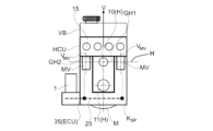
図1は、車両内で車両ブレーキシステムまたはクラッチアクチュエータおよびギヤアクチュエータの圧力供給に使用する本発明に係る操作装置の可能な一実施の形態を示している。本実施の形態において、モータMは、第1のシリンダピストンユニットの軸線Hに対して平行な第2の水平軸線H1上に配置されている。この軸線H上には、ペダルプランジャ26が作用しており、ペダルプランジャ26は、図示しないブレーキペダルに結合可能である。軸線H1上には、モータMの他に、圧力供給装置のピストン11も配置可能である。
Figure 1 shows one possible embodiment of an actuating device according to the invention for use in a vehicle for pressure supply of a vehicle brake system or a clutch actuator and a gear actuator. In this embodiment, the motor M is arranged on a second horizontal axis H1 parallel to the axis H of the first cylinder-piston unit. On this axis H, a
主軸線Hには、同じくペダルインタフェースP1と、両ブレーキ回路用の圧力ピストンを有する主シリンダアッセンブリ10、例えば一般的にはTHZまたはEP2015/068696に応じたアッセンブリとが配置されている。これらは、圧力供給装置のコンポーネント、例えばピストンシリンダアッセンブリ11とともに、ハウジングユニットGH1の構成部材である。第1のハウジングGH1には、圧力供給装置11を駆動するモータMがフランジ固定されている。上方または鉛直方向には、ホイールブレーキに通じる端面側の接続部15を有する弁装置HCUと、貯蔵容器VBとがポジショニングされている。下方には、コネクタ1を有する開ループ・閉ループ制御ユニットECUが配置されており、コネクタ1は、接点KSを介してPCB25に接続されている。
Arranged on the main axis H are likewise the pedal interface P1 and the
図1aは、図1の操作装置の部分断面図XXである。この場合、横断面図で見てU字形に形成される開ループ・閉ループ制御ユニットECUは、ハウジングユニットGH1を下方より取り囲み、THZピストン10は、圧力供給装置のピストン11の上方に配置されている。第1のハウジングGH1の上方には、弁装置HCUが配置されており、弁装置HCUは、第1のハウジングGH1の両側に、鉛直の軸線VMVを有する電磁弁MVを収容している。電磁弁MVは、その下側で接点KSPにより開ループ・閉ループ制御ユニットECUの回路板PCBに電気的に接続されている。コネクタ1は、端面に代えて開ループ・閉ループ制御ユニットECUの側方に配置されていてもよい。前述した特徴により、開ループ・閉ループ制御ユニットECU、圧力供給装置11およびピストンシリンダユニット10ならびに弁装置HCUを鉛直方向に積み重ねた極度に細身の構造形式が得られる。加えてこのことは、すべての液圧式のコンポーネントの良好な空気抜きが可能な、極度にコンパクトな構造形式を生じる。
1a is a partial cross-sectional view XX of the operating device of FIG. 1. In this case, the open-loop/closed-loop control unit ECU, which is U-shaped in cross section, surrounds the housing unit GH1 from below, and the
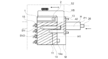
図2は、操作軸線Hに対して平行なモータMおよび圧力供給部11の軸線H1を有するハウジング構造および主コンポーネントの代替的なアッセンブリを示しており、ここでペダルプランジャ26は、ペダルインタフェースP1に作用し、ペダルインタフェースP1は、少なくとも1つの圧力ピストンと、ペダルストロークセンサ操作部とに結合されている。本明細書ではセンサについて深入りすることはしない。通常はホール素子が使用される。
Figure 2 shows an alternative assembly of the housing structure and main components with the axis H1 of the motor M and the
モータMは、遮音性の材料からなる中間部材14を介してハウジングユニットGH1に取り付けねじ14aにより結合されている。中間部材14により、モータMおよびピストン駆動部、例えばKGTの高周波の振動は低減される。第1のハウジングユニットGH1は、本実施の形態では、横断面図で見てL字形の構造形態を呈しており、端面側でフランジ13に結合されている。フランジ13は、前壁にねじ42により取り付けられる。
The motor M is connected to the housing unit GH1 by means of an
モータMは、その駆動に伴い、好ましくはKGTを介して圧力供給ユニットのピストン11に作用する。この場合、このピストン解決手段、特にダブルアクションピストンでは、特に短い構造長さを可能にする点で、有利である。それというのも、前進ストロークおよび後進ストロークを介して連続的に媒体体積を圧送することで、ピストンストロークは、小さく維持され得るからである。これは、前進ストロークおよび後進ストロークのために、貯蔵容器VBに接続された2つの吸い込み弁SV1およびSV2を有している。シングルピストンの場合は、1つの吸い込み弁のみが必要である。端面側には、ホイールブレーキシリンダ用の接続部15が設けられており、これにより接続部15には、最適にアクセス可能である。第1のハウジングGH1の上方には、コネクタ1が配置されており、コネクタ1は、線路ハーネスの好ましくは側方の引き出し部2を有している。これにより、搭載電源網への短い線路長さが可能である。本実施の形態では、貯蔵容器VBは、部分的にコネクタの上方および側方と、アッセンブリの後面に沿って延在している。このことは、車両の電気的な搭載電源網ボックスがストラットドームの前または後に位置することにつながる。上述したことは、ペダルプランジャをx方向で見た図2aにさらに分かりやすく示してある。
When the motor M is driven, it acts on the
図2aには、右側に、第1のハウジングユニットGH1を示してあり、第1のハウジングユニットGH1は、ピストンシリンダユニット10(軸線H)と、圧力供給ユニットのピストン11(軸線H1)とを収容している。 Figure 2a shows on the right side the first housing unit GH1, which accommodates the piston-cylinder unit 10 (axis H) and the piston 11 (axis H1) of the pressure supply unit.
好ましくは、ピストンシリンダユニット10,11は、1つの鉛直の軸線上に配置されており、ストロークシミュレータWSと切り換え弁SV1,SV2とは、主として電磁弁MVと単数または複数の圧力トランスデューサとを収容する弁装置HCUに対してできる限り小さな間隔を置いて配置されている。システムコンセプトに応じて、本実施の形態では、約10~25個の電磁弁MVが、ABS/ESPの圧力制御や、圧力供給装置11、ピストンシリンダユニット10およびストロークシミュレータWSの制御のために必要である。加えて、ピストンシリンダユニットから貯蔵容器VBおよび圧力トランスデューサへ向けて、逆止弁が設けられていてもよい。本発明に係るアッセンブリにより、例えばストロークシミュレータ回路用の電磁弁MVが、ストロークシミュレータピストンの横に配置されているとき、短い孔長さが必要であるにすぎない。これにより僅かなコストおよび流動抵抗が達成される。弁装置HCUの横に開ループ・閉ループ制御ユニットECUがフランジ固定されている。開ループ・閉ループ制御ユニットECUの回路板PCB25は、コイル接点KSPを介して電磁弁コイルに接続されている。同じくモータMは、電気的な接続要素12により回路板PCBに接続されている。このアッセンブリについては、図3を参照しながら詳しく説明する。
Preferably, the piston-
既に言及したように、本明細書では、ペダルストローク、モータ回転、液圧液体のレベルのセンサについて深入りして説明することはしない。目標は、すべてのセンサ要素がシステム回路板PCB25上に配置されており、センサのターゲットがシステム回路板の近傍に配置されており、かつシステム要素に対して僅かな間隔(<5mm)を有していることである。接点が設けられたコネクタ部分は、本実施の形態では、好ましくは、いわゆる圧入接点を介してPCBに接続される。コネクタ1は、本実施の形態では、側方で一般的な機構により嵌合される。コネクタ1は、図2および2aに示した箇所で、特に良好にアクセス可能である。貯蔵容器VBは、コネクタ領域1に空所を有している。液圧消費器、特にホイールブレーキ15の接続部は、鉛直の方向で重ね合わせに配置されることも、水平方向で隣り合わせに配置されることもできる。水平に配置した場合は、第1のハウジング内に接続孔が設けられるべきである。
As already mentioned, the sensors for the pedal stroke, the motor revolutions and the hydraulic liquid level are not described in detail here. The aim is that all sensor elements are arranged on the system circuit board PCB25 and that the sensor targets are arranged close to the system circuit board and have a small distance (<5 mm) to the system elements. The connector parts with the contacts are preferably connected to the PCB in this embodiment via so-called press-fit contacts. The
両ハウジング部分GH1およびGH2は、相俟って1つのハウジングを形成することができるか、または別々に形成されている。 The two housing parts GH1 and GH2 can together form one housing or can be formed separately.
操作機構は、ハウジングフランジ13により車両の前壁に取り付け可能である。この場合、フランジの右側では、良好にアクセス可能にいわゆる「フロントボルト固定型(front bolted)」ねじが使用され、左側では、「リヤボルト固定型(rear bolted)」ねじが使用可能である。例えば1つのねじだけが「フロントボルト固定型」、つまり車両の前方よりアクセス可能であれば、十分である。これにより、あらゆる組み立て可能性が実現可能である。
The operating mechanism can be attached to the front wall of the vehicle by means of a
公知のようにあらゆるシールは漏れる可能性があり、漏れは、もはや外部に漏出してはならないので、本実施の形態では、第1のハウジングGH1の下面に、例えば14cと組み合わされて、漏れリザーバ50を形成することができる。
As is well known, all seals can leak and leakage must no longer occur to the outside, so in this embodiment, a
回路板PCBおよび電子式の構成部品の熱は、熱伝導体26を介して弁装置HCUに伝導され、放熱され得る。開ループ・閉ループ制御ユニットECUは、平らに、または、より大きな回路板面積が必要な場合は、下側で直角に構成され得る。
The heat of the circuit board PCB and electronic components can be conducted and dissipated to the valve unit HCU via
構成スペース獲得を評価するために、ここでは小型の真空式BKVの周囲輪郭を記入してある。右側には、電気的な機器、例えばバッテリ用の付加的な容積が生じている。この構成スペース獲得は、特に右ハンドルの場合に重要である。それというのも、右ハンドルの場合、横置きされたエンジンが、多くのスペースを必要とするからである。 To assess the space available, the outline of a small vacuum BKV has been drawn here. On the right side, additional volume is available for electrical equipment, such as the battery. This space available is particularly important for right-hand drive vehicles, since the transversely mounted engine requires a lot of space in this case.
ハウジング部分GH1またはGH2内には、ピストンおよびばねを有するブレーキシステムのストロークシミュレータも、格納することができる。その際、ストロークシミュレータは、主シリンダの軸線に対して軸線平行に配置されても、これに対して垂直に配置されてもよい。 A stroke simulator of the brake system with a piston and a spring can also be accommodated in the housing part GH1 or GH2. In this case, the stroke simulator can be arranged axially parallel to the axis of the main cylinder or perpendicular to it.
図2には、一点鎖線により、THZの部片とともに2チャンバ型真空式制動倍力装置(2-Kammer-Vacuum-Bremskraftverstaerker)の周囲輪郭52(例えば9インチの直径を有する小型の真空式倍力装置)を示してある。本発明に係るアッセンブリにより可能なスペース獲得は、直ちに明らかとなる。ここでは、略50%の構造長さ獲得、小型のBKVの場合は、略40%の構造長さ獲得が可能である。図2aには、円51により約9インチの小型の真空式BKVの周囲輪郭を示してある。ここでは、貯蔵容器VBとともにハウジング部分GH1およびGH2により規定されて、本発明に係る制動倍力装置の明らかな構成スペース獲得が明らかである。
2 shows the
図3は、モータ、駆動部、圧力供給装置DK、弁装置HCUおよび開ループ・閉ループ制御ユニットECUの横断面図をそれらの主要なコンポーネントとともに示している。この図示は、図2に示した図示の鏡像反転である。 Figure 3 shows a cross-sectional view of the motor, drive, pressure supply device DK, valve device HCU and open-loop and closed-loop control unit ECU with their main components. This illustration is a mirror image of the illustration shown in Figure 2.
モータハウジング16は、好ましくは遮音性の材料からなる中間部材14を介して第1のハウジング部分GH1に結合されており、このときセンタリングは、延長部14bを介して実施可能である。モータハウジング16、中間部材14およびECUハウジング35は、封止、例えば矩形にハッチングを施した面でもって封止されている。この面について詳しく説明することはしない。モータハウジング16内には、4点軸受20が圧入されており、4点軸受20は、スピンドル25およびロータ22からの両方向の軸方向力を受け、スピンドル25およびロータ22をセンタリングしている。ロータ22は、軸方向リテーニング部29を介して保持されており、ステータ領域において一般的なロータ金属薄板19を磁石20とともに担持している。
The
さらにロータ22は、端面側で傘歯車28に結合されており、傘歯車28は、第2の傘歯車29を軸41およびターゲット38とともに駆動する。ターゲット38は、ロータ回転を評価するセンサ要素37に対して作用する。この場合、センサ要素は、システム回路板PCBに載置されており、特に低コストであり、障害に対して強い。この機械的な解決手段に代えて、ロータが、円錐車に結合される代わりに、スリーブに結合され、スリーブが、磁石を含み、これにより、モータの回転角を評価するためのターゲット38を形成している図示しない解決手段が実現されてもよい。この場合、ターゲット磁界は、センサ要素をターゲットの近傍に(例えばECUとの差し込み接続により)相応に配置することで検出され得るか、あるいは磁束伝導要素を介してPCB上の離れたセンサ要素へ案内され得る。
Furthermore, the
傘歯車29は、ハウジング40内に支承されており、ハウジング40は、モータハウジング16に結合されている。歯車20は、可撓性の駆動軸41が相応に変形することでバックラッシがないように、ハウジング内に半径方向の遊びSRをもって支持されている。この場合、軸は、中間部材14内に取り付けられた軸受ブシュ41内に支持されている。軸41は、歯車29に相対回動不能に結合、例えば回り止めを有する相応の輪郭を介して結合されている。ロータ22には、撓み棒BSが、ナット23を介して取り付けられている。撓み棒BSは、スピンドル25に相対回動不能に、例えば溶接部30により結合されている。スピンドル25は、KGTナット26に作用し、KGTナット26は、例えばねじ山27を介して相対回動不能にピストン11に結合されている。ロータ22およびスピンドル25の回転時、半径方向の公差は、スピンドル揺動を引き起こし、スピンドル揺動は、ピストンに相応に高い横方向力を発生させてしまう。この横方向力は、シールDKの摺動面にとって問題である。撓み棒BSの曲げ弾性は、この横方向力を小さな値に低減する。この原理は、図示しない定置のスピンドルおよび回転するナットの場合にも適用可能である。本実施の形態では、ピストンは、段付きピストンとして構成されており、小さなストローク時、短い構造長さを生じる。断面図が示しているように、構造長さは、ストロークH1+H2=2×H1+KGTナットのLから構成されている。これは、KGTナットは、本件出願人のDE102008063772に応じたモータ、中空軸モータ内に配置されているので、ステータと軸受とから構成される本来のモータ構造長さは、この構造長さには含まれない。ストローク成分H1のフリースペースは、巻線のリードフレーム31のために使用される。リードフレーム31は、巻線線材に接続されている。付加的に、ここには、既に説明したように、さらにモータセンシング部28~29が格納され得る。
The
ピストンは、対応する圧力室を封止すべく、3つのシールDKを介して封止される。本明細書ではシールDKの詳細について深入りすることはしない。中間部材14およびGH1の、このために最適な構成についても深入りすることはしない。
The pistons are sealed off via three seals DK to seal the corresponding pressure chambers. The details of the seals DK will not be described in detail here, nor will the optimal configuration of the
ピストンを備えるKGTナットは、回り止めを必要とする。回り止めは、本実施の形態では、端面側で取着されている。四角形または多角形の輪郭を有する対応する部分33は、GH1に相対回動不能に結合されており、滑りブシュ34に支持されている。滑りブシュ34は、相対回動不能にピストンに結合されている。この滑り案内は、ブレーキ液体の小さな潤滑作用に乗じる。ピストン駆動は、定置のスピンドルおよび回転するKGTナットにより実施されてもよい。GH1の一方の側には、吸い込み弁SV1およびSV2が格納されており、吸い込み弁SV1およびSV2は、貯蔵容器VBに通じている対応する接続部に接続されている。一点鎖線で略示したように、これらは、H2のレベルで管形の要素内に配置され得る。反対側には、GH2-HCU(弁装置)が配置され、GH2-HCUは、既に説明したように、MVおよびその他の弁を圧力トランスデューサとともに収容している。この場合、上下にGH1およびGH2の極めて短い接続孔が明瞭に看取可能である。
The KGT nut with the piston requires a detent, which in this embodiment is attached at the end face side. The
ハウジング部分GH2には、ECUハウジングが結合されており、ECUハウジングは、構成要素BEを有する回路板PCBを収容している。ここには、リードフレーム31からモータあるいはモータ接点KMへの短い電気的な接続も示してあり、モータ接点KMの近傍には、PCB上に、コネクタ1のパワー接点が、モータ制御用のBEとともに配置されている。相応の損失出力は、PCBから熱伝導体を介してHCUの弁ブロック56に導出される。ECUハウジング35は、モータに対して平行にかつ側方で構成され得る。このアッセンブリにより、多くの要求を考慮した有利なコンパクトな解決手段が、低コストに実現され得る。
An ECU housing is connected to the housing part GH2, which accommodates the circuit board PCB with the components BE. A short electrical connection from the
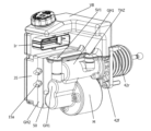
図4は、斜視図で、ABS/ESPユニットが機器室内に配置されているE-BKV(電気式制動倍力装置)に関する実施の形態におけるアッセンブリのコンパクト性を特に明瞭に示している。それゆえ15aにより、ABS/ESP用機器の両ブレーキ回路の2つの液圧式の接続線路のみが、図2、2aに示したような統合型のバージョンにおけるホイール回路に通じる4つの液圧式の接続線路と対比させて示されている。主コンポーネント、図3に対応する圧力供給部を有するモータ、ハウジングユニットGH1およびGH2ならびにECUの配置における主要な相違点は、存在しないので、両バージョンは、モジュール式に構成され、製造され得る。ECU、GH2内のコンポーネント、例えば電磁弁の数および複数の吸い込み弁を有する圧力供給部のピストンのGH3の構成のみが相違する。 Figure 4, in a perspective view, particularly clearly shows the compactness of the assembly in the embodiment for an E-BKV (electric brake booster) in which the ABS/ESP unit is arranged in the equipment compartment. Therefore, with 15a, only two hydraulic connections of both brake circuits of the ABS/ESP equipment are shown, in contrast to the four hydraulic connections to the wheel circuits in the integrated version as shown in Figures 2 and 2a. There are no major differences in the arrangement of the main components, the motor with pressure supply corresponding to Figure 3, the housing units GH1 and GH2 and the ECU, so that both versions can be constructed and manufactured modularly. Only the components in the ECU, GH2, such as the number of solenoid valves and the configuration of the piston GH3 of the pressure supply with several intake valves, differ.
コネクタ1cは、ECUに接続されるいわゆるオス部分のみを示している。貯蔵容器VBは、1つの吸い込み弁SV1にのみ接続されている。ハウジングフランジ内に設けられた主シリンダとの第2の接続部THZは、前方から取り付けるためのフロントボルト固定型の1つのねじ42であり、42rが付されたその他の1ないし3つのねじは、リヤボルト固定型として設けられている。
The connector 1c shows only the so-called male part that is connected to the ECU. The storage container VB is connected to only one intake valve SV1. The second connection THZ with the main cylinder provided in the housing flange is one
図4aは、互いにねじ止めされたハウジング部分GH1とハウジング部分GH2と間の液圧式の案内板HLP50の配置を示している。液圧式の案内板HLP50は、相応の通路により、弁ブロック内に設けられる多くの孔と、孔の出口に設けられる盲栓とに置換される。これらは、例えばTHZ、圧力供給部、電磁弁の液圧式の線路を接続するために必要である。HLPは、数を減じ、特に長さを減じ、かつより薄い弁ブロック(GH2)を実現し、このことは、重量を削減する。封止のために、リップシールD1または矩形シールが使用可能である。好ましくは、リップシールD1または矩形シールは、HLPに射出成形により付着される。 Figure 4a shows the arrangement of the hydraulic guide plate HLP50 between the housing parts GH1 and GH2 which are screwed together. The hydraulic guide plate HLP50 replaces the numerous holes in the valve block with corresponding passages and blind plugs at the hole outlets. These are necessary, for example, to connect the hydraulic lines of the THZ, the pressure supply and the solenoid valves. The HLP allows for a reduced number, especially reduced length, and a thinner valve block (GH2), which reduces the weight. For sealing, lip seals D1 or rectangular seals can be used. Preferably, the lip seals D1 or rectangular seals are applied to the HLP by injection molding.
Claims (15)
-ブレーキペダルあるいはクラッチ操作装置の形態の操作装置用の接続部と、
-ピストンポンプまたはダブルアクションピストンポンプの形態の、電気モータ式の駆動部により駆動される圧力供給装置であって、前記電気モータ式の駆動部は、直接的に、または変換伝動機構を介して、前記ピストンポンプまたはダブルアクションピストンポンプのピストンを調節する、圧力供給装置と、
-前記操作装置により操作可能なピストン-シリンダ-ユニットであって、液圧的に圧力媒体貯蔵容器に接続されているピストン-シリンダ-ユニットと、
-電子式の制御ユニットと、
を備える操作装置において、
接続要素が、前記ピストン-シリンダ-ユニットの軸線に垂直の差し込み方向で前記電子式の制御ユニット内に差し込み可能であり、前記接続要素は、前記ピストン-シリンダ-ユニットの上方に配置されており、前記ピストン-シリンダ-ユニットを少なくとも部分的に覆う、
ことを特徴とする、操作装置。 1. An actuation device for a hydraulic actuation system of a vehicle, comprising the following components:
- a connection for an actuator in the form of a brake pedal or a clutch actuator,
a pressure supply device in the form of a piston pump or a double-action piston pump, driven by an electric motor drive, which adjusts the piston of said piston pump or double-action piston pump either directly or via a converter transmission;
a piston-cylinder unit operable by said actuation device, said piston-cylinder unit being hydraulically connected to a pressure medium reservoir;
- an electronic control unit,
In an operating device comprising:
a connecting element is insertable into the electronic control unit in an insertion direction perpendicular to the axis of the piston-cylinder unit, the connecting element being arranged above the piston-cylinder unit and at least partially covering the piston-cylinder unit ;
An operating device comprising:
Priority Applications (2)
| Application Number | Priority Date | Filing Date | Title |
|---|---|---|---|
| JP2024068356A JP7781208B2 (en) | 2016-03-21 | 2024-04-19 | Operating device for hydraulic operating system |
| JP2025203215A JP2026032128A (en) | 2016-03-21 | 2025-11-25 | Operating device for hydraulic operating system |
Applications Claiming Priority (4)
| Application Number | Priority Date | Filing Date | Title |
|---|---|---|---|
| DE102016105232.9A DE102016105232A1 (en) | 2016-03-21 | 2016-03-21 | Actuating device for a hydraulic actuation system, in particular a motor vehicle brake or an electrified clutch and gear actuator |
| DE102016105232.9 | 2016-03-21 | ||
| PCT/EP2017/056567 WO2017162593A1 (en) | 2016-03-21 | 2017-03-20 | Actuating device for a hydraulic actuating system |
| JP2018549513A JP7051698B2 (en) | 2016-03-21 | 2017-03-20 | Operating equipment for hydraulic operating systems |
Related Parent Applications (1)
| Application Number | Title | Priority Date | Filing Date |
|---|---|---|---|
| JP2018549513A Division JP7051698B2 (en) | 2016-03-21 | 2017-03-20 | Operating equipment for hydraulic operating systems |
Related Child Applications (1)
| Application Number | Title | Priority Date | Filing Date |
|---|---|---|---|
| JP2024068356A Division JP7781208B2 (en) | 2016-03-21 | 2024-04-19 | Operating device for hydraulic operating system |
Publications (2)
| Publication Number | Publication Date |
|---|---|
| JP2022088562A JP2022088562A (en) | 2022-06-14 |
| JP7586849B2 true JP7586849B2 (en) | 2024-11-19 |
Family
ID=58398167
Family Applications (4)
| Application Number | Title | Priority Date | Filing Date |
|---|---|---|---|
| JP2018549513A Active JP7051698B2 (en) | 2016-03-21 | 2017-03-20 | Operating equipment for hydraulic operating systems |
| JP2022055982A Active JP7586849B2 (en) | 2016-03-21 | 2022-03-30 | Operating device for hydraulic operating system |
| JP2024068356A Active JP7781208B2 (en) | 2016-03-21 | 2024-04-19 | Operating device for hydraulic operating system |
| JP2025203215A Pending JP2026032128A (en) | 2016-03-21 | 2025-11-25 | Operating device for hydraulic operating system |
Family Applications Before (1)
| Application Number | Title | Priority Date | Filing Date |
|---|---|---|---|
| JP2018549513A Active JP7051698B2 (en) | 2016-03-21 | 2017-03-20 | Operating equipment for hydraulic operating systems |
Family Applications After (2)
| Application Number | Title | Priority Date | Filing Date |
|---|---|---|---|
| JP2024068356A Active JP7781208B2 (en) | 2016-03-21 | 2024-04-19 | Operating device for hydraulic operating system |
| JP2025203215A Pending JP2026032128A (en) | 2016-03-21 | 2025-11-25 | Operating device for hydraulic operating system |
Country Status (7)
| Country | Link |
|---|---|
| US (4) | US10933853B2 (en) |
| EP (3) | EP4201764A1 (en) |
| JP (4) | JP7051698B2 (en) |
| KR (2) | KR102346057B1 (en) |
| CN (5) | CN208233037U (en) |
| DE (1) | DE102016105232A1 (en) |
| WO (1) | WO2017162593A1 (en) |
Families Citing this family (39)
| Publication number | Priority date | Publication date | Assignee | Title |
|---|---|---|---|---|
| DE102017113563A1 (en) | 2017-06-20 | 2018-12-20 | Ipgate Ag | braking system |
| CN109572655B (en) * | 2017-09-29 | 2022-09-20 | 株式会社万都 | Actuator of electronic brake system |
| DE102018206082A1 (en) * | 2018-04-20 | 2019-10-24 | Robert Bosch Gmbh | Multi-circuit hydraulic open brake system, especially for a highly automated or autonomous vehicle |
| DE102018206588A1 (en) * | 2018-04-27 | 2019-10-31 | Continental Teves Ag & Co. Ohg | Control arrangement, method for measuring an angle and use of the control arrangement |
| WO2019214835A1 (en) * | 2018-05-09 | 2019-11-14 | Ipgate Ag | Piston-cylinder system having separate bearing and sealing region |
| DE112019002347A5 (en) | 2018-05-09 | 2021-01-21 | Ipgate Ag | Braking system |
| WO2019215030A1 (en) | 2018-05-09 | 2019-11-14 | Ipgate Ag | Brake system |
| DE102018215716A1 (en) * | 2018-09-14 | 2020-03-19 | Continental Teves Ag & Co. Ohg | Brake system for a motor vehicle |
| DE102018221450A1 (en) * | 2018-12-11 | 2020-06-18 | Mando Corporation | Brake actuation unit for a brake-by-wire motor vehicle brake system and motor vehicle brake system |
| US12071118B2 (en) | 2019-02-12 | 2024-08-27 | Ipgate Ag | Pressure supply device with double stroke piston for a brake system |
| DE102019103483A1 (en) * | 2019-02-12 | 2020-08-13 | Ipgate Ag | Packaging for a braking system |
| DE102019103464A1 (en) | 2019-02-12 | 2020-08-13 | Ipgate Ag | Hydraulic system with at least two hydraulic circuits and at least two pressure supply devices |
| DE202019101596U1 (en) | 2019-02-12 | 2020-05-13 | Ipgate Ag | Hydraulic system with at least two hydraulic circuits and at least two pressure supply devices |
| JP2022520243A (en) | 2019-02-12 | 2022-03-29 | アイピーゲート・アクチェンゲゼルシャフト | Fail-safe braking system |
| DE202019101586U1 (en) | 2019-02-12 | 2020-05-13 | Ipgate Ag | Packaging for a braking system |
| CN118405104A (en) | 2019-02-12 | 2024-07-30 | 爱皮加特股份公司 | Brake system with a pressure supply device and a safety door for a brake circuit |
| DE102019118723A1 (en) | 2019-07-10 | 2021-01-14 | Ipgate Ag | Pressure supply unit for a hydraulic system with at least one consumer circuit and with at least one rotary pump |
| DE102019212353A1 (en) * | 2019-08-19 | 2021-02-25 | Robert Bosch Gmbh | Hydraulic block for a hydraulic unit of an external hydraulic vehicle brake system |
| KR102766232B1 (en) * | 2019-10-24 | 2025-02-12 | 에이치엘만도 주식회사 | Leak detecting device of brake system |
| DE102019219869A1 (en) * | 2019-12-17 | 2021-06-17 | Continental Teves Ag & Co. Ohg | Hydraulic braking device for a motor vehicle braking system with an improved container connection |
| DE102020102590B4 (en) | 2020-01-28 | 2025-01-09 | Ipgate Ag | braking system and method for controlling a braking system |
| DE102020204459A1 (en) * | 2020-04-07 | 2021-10-07 | Robert Bosch Gesellschaft mit beschränkter Haftung | Hydraulic block for a hydraulic unit of an external hydraulic vehicle brake system |
| KR102899794B1 (en) * | 2020-04-16 | 2025-12-12 | 에이치엘만도 주식회사 | Braking system for vehicle |
| DE102020205950A1 (en) * | 2020-05-12 | 2021-11-18 | Robert Bosch Gesellschaft mit beschränkter Haftung | Hydraulic block for a hydraulic unit of an external hydraulic vehicle brake system |
| DE102020207505A1 (en) | 2020-06-17 | 2021-12-23 | Robert Bosch Gesellschaft mit beschränkter Haftung | Hydraulic unit, in particular for controlling and regulating a brake pressure in a brake circuit of an electronically slip-regulated brake system of a motor vehicle and method for assembling a hydraulic unit |
| CN111828720A (en) * | 2020-08-14 | 2020-10-27 | 江苏易恒自动化设备有限公司 | A gas-liquid linkage actuator and gas-liquid linkage control system |
| WO2022050741A1 (en) * | 2020-09-02 | 2022-03-10 | 주식회사 만도 | Device for sensing liquid flowing into housing of electronic control device |
| DE102020212989A1 (en) * | 2020-10-14 | 2022-04-14 | Robert Bosch Gesellschaft mit beschränkter Haftung | Piston pump with helical gear as external power brake pressure generator of a hydraulic external power vehicle brake system |
| DE102020216113A1 (en) * | 2020-12-17 | 2022-06-23 | Robert Bosch Gesellschaft mit beschränkter Haftung | Hydraulic block for a hydraulic unit of a brake pressure control of a hydraulic vehicle brake system |
| DE102021114788B4 (en) * | 2021-06-09 | 2023-11-02 | Schaeffler Technologies AG & Co. KG | Space-saving and safe control unit for the electro-hydraulic actuation of motor vehicle units |
| EP4101707B1 (en) * | 2021-06-12 | 2025-04-09 | BWI (Shanghai) Co., Ltd. | Pressure supply unit for a brake system of a vehicle |
| DE102021119571A1 (en) | 2021-07-28 | 2023-02-02 | Nidec Gpm Gmbh | Pump module, in particular for a thermal management system, and thermal management system having the pump module and motor vehicle having the pump module or the thermal management system |
| KR20230065815A (en) * | 2021-11-05 | 2023-05-12 | 현대모비스 주식회사 | Electric Hydraulic Brake |
| DE102022108721A1 (en) | 2022-04-11 | 2023-10-12 | Heinz Leiber | Master brake cylinder with adjustable pedal characteristics |
| DE102022205437A1 (en) * | 2022-05-30 | 2023-11-30 | Robert Bosch Gesellschaft mit beschränkter Haftung | Actuating device for a brake system, method for producing an actuating device for a brake system |
| KR102661669B1 (en) * | 2022-06-27 | 2024-04-29 | 현대모비스 주식회사 | Brake device for vehicle |
| DE102022119541A1 (en) | 2022-08-04 | 2024-02-29 | Heinz Leiber | Braking system for a vehicle |
| US11951956B2 (en) | 2022-08-30 | 2024-04-09 | ZF Active Safety US Inc. | Single chamber power transmission unit and brake systems using same |
| US12358464B2 (en) * | 2023-10-09 | 2025-07-15 | Bruno Thierry Robert Pellichero | System and method of immobilizing a vehicle to prevent vehicle theft |
Citations (2)
| Publication number | Priority date | Publication date | Assignee | Title |
|---|---|---|---|---|
| JP2007269171A (en) | 2006-03-31 | 2007-10-18 | Advics:Kk | Brake hydraulic control unit |
| DE102011017436A1 (en) | 2011-04-18 | 2012-10-18 | Ipgate Ag | Actuating device for a vehicle brake system |
Family Cites Families (67)
| Publication number | Priority date | Publication date | Assignee | Title |
|---|---|---|---|---|
| JPS642987Y2 (en) * | 1984-10-29 | 1989-01-25 | ||
| JP3611386B2 (en) * | 1995-12-28 | 2005-01-19 | 日信工業株式会社 | Electric brake booster |
| JP3932710B2 (en) * | 1998-12-12 | 2007-06-20 | アイシン精機株式会社 | Hydraulic control unit |
| JP2002280110A (en) | 2001-03-16 | 2002-09-27 | Bosch Braking Systems Co Ltd | Automotive connectors and connector members |
| UA77830C2 (en) | 2002-08-19 | 2007-01-15 | Dynamic separator | |
| DE10245068A1 (en) * | 2002-09-27 | 2004-04-08 | Continental Teves Ag & Co. Ohg | Hydraulic unit for slip-controlled brake systems |
| DE502004005089D1 (en) * | 2003-07-11 | 2007-11-08 | Continental Teves Ag & Co Ohg | ELECTROHYDRAULIC BRAKING SYSTEM FOR MOTOR VEHICLES |
| DE102005015262A1 (en) * | 2005-04-04 | 2006-10-05 | Robert Bosch Gmbh | Pressurized medium accumulator for electronically slip-regulated vehicle brake assembly, has piston with gasket that divides accumulator into separate chambers, where piston is single-piece chipless component made of sheet metal material |
| DE102006015905A1 (en) * | 2005-09-15 | 2007-04-19 | Continental Teves Ag & Co. Ohg | Braking system for motor vehicles |
| CN101896382A (en) * | 2007-10-29 | 2010-11-24 | 凯尔西-海耶斯公司 | Hydraulic brake system with controlled boost |
| DE102009033499A1 (en) * | 2008-07-18 | 2010-01-21 | Continental Teves Ag & Co. Ohg | Brake system for motor vehicles |
| US8113595B1 (en) | 2008-10-30 | 2012-02-14 | Robert Bosch Gmbh | Electric booster with hydraulic transmission |
| DE102008063772A1 (en) | 2008-12-22 | 2010-06-24 | Ipgate Ag | Rotation angle sensor for spindle drives of brake booster, for detecting rotational movement or position of body, particularly shaft, is provided with housings, in which sensor element is arranged for detecting rotational movement of magnet |
| DE102010039916A1 (en) * | 2009-09-01 | 2011-03-03 | Continental Teves Ag & Co. Ohg | linear unit |
| DE102010040097A1 (en) * | 2009-09-11 | 2011-03-31 | Continental Teves Ag & Co. Ohg | Brake system for motor vehicles |
| DE102010040078A1 (en) * | 2010-09-01 | 2012-03-01 | Continental Teves Ag & Co. Ohg | Brake system for motor vehicles |
| DE102012205862A1 (en) * | 2011-04-19 | 2012-10-25 | Continental Teves Ag & Co. Ohg | Brake system for motor vehicles and method for operating a brake system |
| DE102012205860A1 (en) * | 2011-04-19 | 2012-10-25 | Continental Teves Ag & Co. Ohg | Brake system for motor vehicles |
| DE102012205962A1 (en) * | 2011-05-05 | 2012-11-08 | Continental Teves Ag & Co. Ohg | Brake system for motor vehicles and method for operating a brake system |
| DE102011106626A1 (en) * | 2011-06-17 | 2012-12-20 | Ipgate Ag | High dynamic short-drive assembly for brake system of motor car, has hydraulic actuator that is partially provided in inside electric motor provided with rotor in cavity, and integrated transmission for actuating hydraulic actuator |
| DE102012213216A1 (en) * | 2011-08-15 | 2013-02-21 | Continental Teves Ag & Co. Ohg | Brake actuation unit |
| DE102012212836A1 (en) | 2011-08-17 | 2013-02-21 | Continental Teves Ag & Co. Ohg | Braking system for motor vehicle, comprises power input piston guided in borehole of housing along actuation axis in movable manner, and simulation device is provided, which is hydraulically connected with hydraulic pressure chamber |
| DE102012222897A1 (en) * | 2012-02-28 | 2013-08-29 | Continental Teves Ag & Co. Ohg | Method for operating a brake system |
| JP5838875B2 (en) * | 2012-03-16 | 2016-01-06 | トヨタ自動車株式会社 | Hydraulic control device and hydraulic brake system |
| DE102013204778B4 (en) * | 2012-03-22 | 2026-03-26 | Aumovio Germany Gmbh | Methods for providing haptic information to the driver of a motor vehicle |
| US9975532B2 (en) * | 2012-03-30 | 2018-05-22 | Autoliv Nissin Brake Systems Japan Co., Ltd. | Master cylinder apparatus |
| JP2014046853A (en) | 2012-08-31 | 2014-03-17 | Hitachi Automotive Systems Ltd | Electric booster |
| JP5972734B2 (en) * | 2012-09-21 | 2016-08-17 | 日立オートモティブシステムズ株式会社 | Brake unit |
| DE102012222575A1 (en) * | 2012-12-07 | 2014-06-12 | Robert Bosch Gmbh | Hydraulic pump unit for a hydraulic vehicle brake system |
| DE102012223059B4 (en) * | 2012-12-13 | 2025-03-20 | Robert Bosch Gmbh | Hydraulic block for a hydraulic unit of a slip-controlled, hydraulic vehicle brake system |
| JP6197098B2 (en) * | 2013-03-28 | 2017-09-13 | ローベルト ボッシュ ゲゼルシャフト ミット ベシュレンクテル ハフツング | Brake system for vehicles |
| DE102013222281A1 (en) * | 2013-05-02 | 2014-11-06 | Continental Teves Ag & Co. Ohg | Method for haptic information of a driver of a motor vehicle and brake system |
| DE102013111974A1 (en) * | 2013-10-30 | 2015-04-30 | Ipgate Ag | Actuating device for a vehicle brake |
| DE102013226699A1 (en) * | 2013-12-19 | 2015-06-25 | Robert Bosch Gmbh | Arrangement for controlling a medium |
| DE102014207234A1 (en) * | 2014-04-15 | 2015-10-15 | Continental Teves Ag & Co. Ohg | Electrohydraulic actuator |
| JP6217027B2 (en) * | 2014-05-08 | 2017-10-25 | 日立オートモティブシステムズ株式会社 | Brake device |
| DE102014208871A1 (en) * | 2014-05-12 | 2015-11-12 | Robert Bosch Gmbh | Hydraulic block for a hydraulic unit of a slip control of a hydraulic vehicle brake system |
| DE102014212409A1 (en) * | 2014-06-27 | 2015-12-31 | Robert Bosch Gmbh | Pressure generator for a hydraulic vehicle brake system |
| JP6375542B2 (en) * | 2014-07-15 | 2018-08-22 | 日立オートモティブシステムズ株式会社 | Brake device and master cylinder |
| DE102014111594A1 (en) | 2014-08-13 | 2016-02-18 | Ipgate Ag | Actuation system, in particular for a vehicle brake, and method for operating the actuation system |
| US10407040B2 (en) * | 2014-10-17 | 2019-09-10 | Mando Corporation | Hydraulic unit of electronic control brake system |
| CN105523026B (en) * | 2014-10-21 | 2018-09-28 | 株式会社万都 | Integrated power brake system |
| JP6267094B2 (en) * | 2014-10-21 | 2018-01-24 | オートリブ日信ブレーキシステムジャパン株式会社 | VEHICLE CONTROL DEVICE AND VEHICLE BRAKE SYSTEM |
| DE102014225590A1 (en) * | 2014-12-11 | 2016-06-16 | Robert Bosch Gmbh | Piston assembly for a pressure generating device, pressure generating device, hydraulic unit for interacting with the pressure generating device, brake system and method for mounting the piston assembly for the pressure generating device |
| DE102014225595A1 (en) * | 2014-12-11 | 2016-06-16 | Robert Bosch Gmbh | Pressure generating device for a brake system of a motor vehicle, hydraulic unit for interacting with the pressure generating device, brake system and method for mounting a brake system for a motor vehicle |
| DE102014225962A1 (en) * | 2014-12-16 | 2016-06-16 | Continental Teves Ag & Co. Ohg | Brake system for motor vehicles |
| KR20160080899A (en) * | 2014-12-29 | 2016-07-08 | 주식회사 만도 | Electric intergrated hydraulic brake |
| US9776604B2 (en) * | 2014-12-30 | 2017-10-03 | Mando Corporation | Integrated brake device for vehicle |
| US10017168B2 (en) * | 2015-02-13 | 2018-07-10 | Autoliv Nissin Brake Systems Japan Co., Ltd. | Brake system |
| DE102015104246A1 (en) * | 2015-03-20 | 2016-09-22 | Ipgate Ag | Actuating device for a motor vehicle brake |
| DE102015214584B4 (en) * | 2015-07-31 | 2024-11-07 | Robert Bosch Gmbh | rotational/translational converter transmission |
| JP6493758B2 (en) * | 2015-08-26 | 2019-04-03 | 日立オートモティブシステムズ株式会社 | Pump device and brake system |
| DE102015222286A1 (en) * | 2015-11-12 | 2017-05-18 | Robert Bosch Gmbh | Hydraulic block and hydraulic unit |
| JP6535952B2 (en) * | 2015-11-20 | 2019-07-03 | 日立オートモティブシステムズ株式会社 | Hydraulic control device and brake system |
| DE102015223507A1 (en) * | 2015-11-27 | 2017-06-01 | Robert Bosch Gmbh | Piston pump unit |
| DE102016202113A1 (en) * | 2016-02-12 | 2017-08-17 | Robert Bosch Gmbh | Hydraulic block for a brake system of a motor vehicle and brake system for a motor vehicle |
| DE102016216344A1 (en) * | 2016-08-30 | 2018-03-01 | Robert Bosch Gmbh | Method for tensioning and machining a hydraulic block of a slip-controlled hydraulic vehicle brake system and hydraulic block |
| DE102016225761A1 (en) * | 2016-09-07 | 2018-03-08 | Robert Bosch Gmbh | Hydraulic block for a hydraulic unit of a slip control of a hydraulic vehicle brake system |
| DE102017204407A1 (en) * | 2017-03-16 | 2018-09-20 | Robert Bosch Gmbh | Hydraulic block for a hydraulic power-operated vehicle brake system |
| DE102017114556A1 (en) * | 2017-06-29 | 2019-01-03 | Ipgate Ag | Device for a hydraulic actuation system |
| DE102017211873A1 (en) * | 2017-07-12 | 2019-01-17 | Robert Bosch Gmbh | Piston pump unit for a hydraulic power-operated vehicle brake system |
| DE102017214593A1 (en) * | 2017-08-22 | 2019-02-28 | Robert Bosch Gmbh | Piston pump unit for a hydraulic power-operated vehicle brake system |
| KR102425546B1 (en) * | 2017-09-29 | 2022-07-29 | 주식회사 만도 | Actuator of Electric brake system |
| CN109572655B (en) * | 2017-09-29 | 2022-09-20 | 株式会社万都 | Actuator of electronic brake system |
| CN110395234B (en) * | 2018-08-12 | 2021-10-08 | 京西重工(上海)有限公司 | Electro-hydraulic brake system |
| DE202019101586U1 (en) * | 2019-02-12 | 2020-05-13 | Ipgate Ag | Packaging for a braking system |
| DE102020212989A1 (en) * | 2020-10-14 | 2022-04-14 | Robert Bosch Gesellschaft mit beschränkter Haftung | Piston pump with helical gear as external power brake pressure generator of a hydraulic external power vehicle brake system |
-
2016
- 2016-03-21 DE DE102016105232.9A patent/DE102016105232A1/en active Pending
-
2017
- 2017-03-20 EP EP22205854.7A patent/EP4201764A1/en active Pending
- 2017-03-20 JP JP2018549513A patent/JP7051698B2/en active Active
- 2017-03-20 EP EP24162123.4A patent/EP4403426A3/en active Pending
- 2017-03-20 WO PCT/EP2017/056567 patent/WO2017162593A1/en not_active Ceased
- 2017-03-20 CN CN201720274215.1U patent/CN208233037U/en active Active
- 2017-03-20 CN CN201720273834.9U patent/CN207617706U/en active Active
- 2017-03-20 KR KR1020187030350A patent/KR102346057B1/en active Active
- 2017-03-20 KR KR1020217042737A patent/KR102457126B1/en active Active
- 2017-03-20 EP EP17712743.8A patent/EP3433147B1/en active Active
- 2017-03-20 US US16/086,896 patent/US10933853B2/en active Active
- 2017-03-20 CN CN201720275054.8U patent/CN207864604U/en active Active
- 2017-03-20 CN CN201780019150.9A patent/CN108778869B/en active Active
- 2017-03-20 CN CN201720275052.9U patent/CN207860167U/en active Active
-
2021
- 2021-01-20 US US17/153,186 patent/US11554765B2/en active Active
-
2022
- 2022-03-30 JP JP2022055982A patent/JP7586849B2/en active Active
- 2022-12-02 US US18/074,192 patent/US11897439B2/en active Active
-
2024
- 2024-01-12 US US18/411,517 patent/US12325389B2/en active Active
- 2024-04-19 JP JP2024068356A patent/JP7781208B2/en active Active
-
2025
- 2025-11-25 JP JP2025203215A patent/JP2026032128A/en active Pending
Patent Citations (2)
| Publication number | Priority date | Publication date | Assignee | Title |
|---|---|---|---|---|
| JP2007269171A (en) | 2006-03-31 | 2007-10-18 | Advics:Kk | Brake hydraulic control unit |
| DE102011017436A1 (en) | 2011-04-18 | 2012-10-18 | Ipgate Ag | Actuating device for a vehicle brake system |
Also Published As
| Publication number | Publication date |
|---|---|
| US20210213924A1 (en) | 2021-07-15 |
| JP2022088562A (en) | 2022-06-14 |
| EP3433147B1 (en) | 2022-11-09 |
| KR102457126B1 (en) | 2022-10-19 |
| WO2017162593A1 (en) | 2017-09-28 |
| KR102346057B1 (en) | 2021-12-31 |
| CN108778869A (en) | 2018-11-09 |
| JP2019509215A (en) | 2019-04-04 |
| US20230094770A1 (en) | 2023-03-30 |
| JP7781208B2 (en) | 2025-12-05 |
| US10933853B2 (en) | 2021-03-02 |
| CN207617706U (en) | 2018-07-17 |
| US20240149848A1 (en) | 2024-05-09 |
| JP2024096998A (en) | 2024-07-17 |
| US20190100182A1 (en) | 2019-04-04 |
| JP2026032128A (en) | 2026-02-25 |
| EP3433147A1 (en) | 2019-01-30 |
| CN208233037U (en) | 2018-12-14 |
| KR20220000954A (en) | 2022-01-04 |
| EP4403426A3 (en) | 2024-12-11 |
| US12325389B2 (en) | 2025-06-10 |
| JP7051698B2 (en) | 2022-04-11 |
| CN207864604U (en) | 2018-09-14 |
| EP4403426A2 (en) | 2024-07-24 |
| US11554765B2 (en) | 2023-01-17 |
| US11897439B2 (en) | 2024-02-13 |
| CN108778869B (en) | 2022-08-12 |
| DE102016105232A1 (en) | 2017-09-21 |
| CN207860167U (en) | 2018-09-14 |
| KR20180123130A (en) | 2018-11-14 |
| EP4201764A1 (en) | 2023-06-28 |
Similar Documents
| Publication | Publication Date | Title |
|---|---|---|
| JP7586849B2 (en) | Operating device for hydraulic operating system | |
| US12084018B2 (en) | Device for a hydraulic actuating system | |
| US10549737B2 (en) | Actuating device for a motor vehicle brake |
Legal Events
| Date | Code | Title | Description |
|---|---|---|---|
| A521 | Request for written amendment filed |
Free format text: JAPANESE INTERMEDIATE CODE: A523 Effective date: 20220426 |
|
| A621 | Written request for application examination |
Free format text: JAPANESE INTERMEDIATE CODE: A621 Effective date: 20220426 |
|
| A977 | Report on retrieval |
Free format text: JAPANESE INTERMEDIATE CODE: A971007 Effective date: 20230425 |
|
| A131 | Notification of reasons for refusal |
Free format text: JAPANESE INTERMEDIATE CODE: A131 Effective date: 20230509 |
|
| A601 | Written request for extension of time |
Free format text: JAPANESE INTERMEDIATE CODE: A601 Effective date: 20230809 |
|
| A521 | Request for written amendment filed |
Free format text: JAPANESE INTERMEDIATE CODE: A523 Effective date: 20230920 |
|
| A02 | Decision of refusal |
Free format text: JAPANESE INTERMEDIATE CODE: A02 Effective date: 20231220 |
|
| A61 | First payment of annual fees (during grant procedure) |
Free format text: JAPANESE INTERMEDIATE CODE: A61 Effective date: 20241107 |
|
| R150 | Certificate of patent or registration of utility model |
Ref document number: 7586849 Country of ref document: JP Free format text: JAPANESE INTERMEDIATE CODE: R150 |