JP7586842B2 - Selective mode signal transfer between serially chained devices - Google Patents
Selective mode signal transfer between serially chained devices Download PDFInfo
- Publication number
- JP7586842B2 JP7586842B2 JP2021569844A JP2021569844A JP7586842B2 JP 7586842 B2 JP7586842 B2 JP 7586842B2 JP 2021569844 A JP2021569844 A JP 2021569844A JP 2021569844 A JP2021569844 A JP 2021569844A JP 7586842 B2 JP7586842 B2 JP 7586842B2
- Authority
- JP
- Japan
- Prior art keywords
- sbu
- signal
- local
- tbu
- fbu
- Prior art date
- Legal status (The legal status is an assumption and is not a legal conclusion. Google has not performed a legal analysis and makes no representation as to the accuracy of the status listed.)
- Active
Links
- 238000012546 transfer Methods 0.000 title description 3
- 230000004044 response Effects 0.000 claims description 172
- 238000000034 method Methods 0.000 claims description 69
- 238000001514 detection method Methods 0.000 claims description 28
- 230000005540 biological transmission Effects 0.000 description 55
- 238000010586 diagram Methods 0.000 description 18
- 238000011144 upstream manufacturing Methods 0.000 description 13
- 230000002457 bidirectional effect Effects 0.000 description 11
- 239000004020 conductor Substances 0.000 description 11
- 238000012545 processing Methods 0.000 description 9
- 238000012937 correction Methods 0.000 description 5
- 239000000758 substrate Substances 0.000 description 5
- 230000001360 synchronised effect Effects 0.000 description 5
- 230000009471 action Effects 0.000 description 3
- 230000006855 networking Effects 0.000 description 3
- 230000011664 signaling Effects 0.000 description 3
- 125000004122 cyclic group Chemical group 0.000 description 2
- 238000009429 electrical wiring Methods 0.000 description 2
- 230000006870 function Effects 0.000 description 2
- 230000010354 integration Effects 0.000 description 2
- 230000013011 mating Effects 0.000 description 2
- 238000012544 monitoring process Methods 0.000 description 2
- 230000008569 process Effects 0.000 description 2
- 230000002618 waking effect Effects 0.000 description 2
- 230000002776 aggregation Effects 0.000 description 1
- 238000004220 aggregation Methods 0.000 description 1
- 230000007175 bidirectional communication Effects 0.000 description 1
- 230000006854 communication Effects 0.000 description 1
- 238000004891 communication Methods 0.000 description 1
- 238000010276 construction Methods 0.000 description 1
- 238000013461 design Methods 0.000 description 1
- 239000000446 fuel Substances 0.000 description 1
- 238000009413 insulation Methods 0.000 description 1
- 239000004973 liquid crystal related substance Substances 0.000 description 1
- 238000012986 modification Methods 0.000 description 1
- 230000004048 modification Effects 0.000 description 1
- 239000013307 optical fiber Substances 0.000 description 1
- 230000002093 peripheral effect Effects 0.000 description 1
- 230000008439 repair process Effects 0.000 description 1
- 230000002441 reversible effect Effects 0.000 description 1
- 238000012360 testing method Methods 0.000 description 1
Images


Classifications
-
- H—ELECTRICITY
- H04—ELECTRIC COMMUNICATION TECHNIQUE
- H04L—TRANSMISSION OF DIGITAL INFORMATION, e.g. TELEGRAPHIC COMMUNICATION
- H04L12/00—Data switching networks
- H04L12/28—Data switching networks characterised by path configuration, e.g. LAN [Local Area Networks] or WAN [Wide Area Networks]
- H04L12/40—Bus networks
- H04L12/40006—Architecture of a communication node
- H04L12/40039—Details regarding the setting of the power status of a node according to activity on the bus
-
- H—ELECTRICITY
- H05—ELECTRIC TECHNIQUES NOT OTHERWISE PROVIDED FOR
- H05K—PRINTED CIRCUITS; CASINGS OR CONSTRUCTIONAL DETAILS OF ELECTRIC APPARATUS; MANUFACTURE OF ASSEMBLAGES OF ELECTRICAL COMPONENTS
- H05K1/00—Printed circuits
- H05K1/02—Details
- H05K1/14—Structural association of two or more printed circuits
-
- H—ELECTRICITY
- H04—ELECTRIC COMMUNICATION TECHNIQUE
- H04L—TRANSMISSION OF DIGITAL INFORMATION, e.g. TELEGRAPHIC COMMUNICATION
- H04L12/00—Data switching networks
- H04L12/28—Data switching networks characterised by path configuration, e.g. LAN [Local Area Networks] or WAN [Wide Area Networks]
- H04L12/40—Bus networks
- H04L12/40006—Architecture of a communication node
- H04L12/40013—Details regarding a bus controller
-
- H—ELECTRICITY
- H04—ELECTRIC COMMUNICATION TECHNIQUE
- H04L—TRANSMISSION OF DIGITAL INFORMATION, e.g. TELEGRAPHIC COMMUNICATION
- H04L12/00—Data switching networks
- H04L12/28—Data switching networks characterised by path configuration, e.g. LAN [Local Area Networks] or WAN [Wide Area Networks]
- H04L12/40—Bus networks
- H04L2012/40267—Bus for use in transportation systems
- H04L2012/40273—Bus for use in transportation systems the transportation system being a vehicle
Landscapes
- Engineering & Computer Science (AREA)
- Computer Networks & Wireless Communication (AREA)
- Signal Processing (AREA)
- Microelectronics & Electronic Packaging (AREA)
- Two-Way Televisions, Distribution Of Moving Picture Or The Like (AREA)
- Small-Scale Networks (AREA)
- Communication Control (AREA)
Description
幾つかの電子システムにおいて、種々の構成要素が、コネクタ及び電気配線を含む物理層によって結合される。幾つかの応用例において、種々の構成要素の機能性に対する限界が、コネクタのコスト、サイズ、及び数、及び/又は電気配線における個々の配線のコスト、サイズ、及び数によって制限され得る。 In some electronic systems, various components are coupled by a physical layer that includes connectors and electrical wiring. In some applications, the limits on the functionality of the various components may be limited by the cost, size, and number of connectors and/or the cost, size, and number of individual wires in the electrical wiring.
説明される例では、回路は、ローカルポート又は第1のシステムポートで入力信号を受信するように適合される。トランシーバが、ローカルウェイクアップ信号に応答して第1のモードに入るように構成され、ローカルウェイクアップ信号に応答して第2のシステムポートでシステムウェイクアップ信号を送信するように構成される。コントローラが、エネルギー検出信号に応答してローカルウェイクアップ信号を生成するように構成される。エネルギー検出器は、第1のシステムポート及びローカルポートに結合され、第2のモードでトランシーバによって受信される第1のシステム入力信号及びローカル入力信号の一方のエネルギーの検出に応答して、エネルギー検出信号を生成するように構成される。 In the described example, the circuit is adapted to receive an input signal at the local port or the first system port. The transceiver is configured to enter the first mode in response to a local wake-up signal and to transmit a system wake-up signal at the second system port in response to the local wake-up signal. The controller is configured to generate the local wake-up signal in response to an energy detect signal. The energy detector is coupled to the first system port and the local port and configured to generate an energy detect signal in response to detecting energy in one of the first system input signal and the local input signal received by the transceiver in the second mode.
図において、同様の参照番号は同様の要素を示し、種々の特徴は必ずしも一定の縮尺通りに描かれているわけではない。 In the figures, like reference numbers indicate like elements and the various features are not necessarily drawn to scale.
種々の電子システムが、共に結合された構成要素を用いてシステムを構成する。システムの機能性が増大すると相互接続の複雑さが増大する。より多くの機能性がシステムに付加されると(例えば、集積化及び処理能力の増大に応答して)、コネクタの端子数が増加し、その結果、コネクタのサイズ、複雑さ、及び/又はコストが増加する。 Various electronic systems use components that are coupled together to form the system. As the functionality of the system increases, the complexity of the interconnections increases. As more functionality is added to a system (e.g., in response to increased integration and processing power), the number of terminals on the connector increases, which in turn increases the size, complexity, and/or cost of the connector.
幾つかの電子システムが、輸送プラットフォーム(航空機又は自動車等)に設置され得る。モバイルプラットフォームの構造における制限(例えば、人的要因、安全性考慮、及び空気力学的特性等に起因する)が、電子システムのコネクタ及びケーブリングに使用可能であったスペースを制限し得る。また、例えば、電子システムが車両のダッシュボード(少なくとも1つのエアバッグを含み得る)に設置される場合等に、(例えば、テスト、交換、及び/又は修理のための)コネクタ及びケーブリングへのアクセスが制限され得る(これは運用コストを増加させる)。 Some electronic systems may be installed on a transportation platform (such as an aircraft or automobile). Constraints in the construction of the mobile platform (e.g., due to human factors, safety considerations, aerodynamics, etc.) may limit the space available for the connectors and cabling of the electronic system. Also, access to the connectors and cabling (e.g., for testing, replacement, and/or repair) may be limited (which increases operational costs), such as when the electronic system is installed in the dashboard of a vehicle (which may include at least one airbag).
モバイルプラットフォームにおいて設置され得る電子システムの例は、自動車の「インフォテインメント(infotainment)」システムであり、このシステムでは、制御ユニット(例えば、ヘッドユニット又は他のデータソース)によってビデオデータが生成され得る(或いは、送信され得る)。生成されたビデオデータは、複数のディスプレイパネル(例えば、ヘッドアップディスプレイ、計器クラスタ、及び中央計器ディスプレイ)に伝送され得る。異なるタイプのディスプレイデータを制御ユニットから異なるディスプレイに送るために、種々のケーブル/コネクタが、制御ユニットと、異なるディスプレイのそれぞれとの間に配置される。2つのユニット(ディスプレイと制御ユニット等)の間で信号を搬送するように適合されたケーブルは、第1のユニットの第1の嵌合コネクタに接続するように適合された第1のコネクタ(例えば、コネクタの第1のセット)、第2のユニットの第2の嵌合コネクタに接続するように適合された第2のコネクタ(例えば、コネクタの第2のセット)、及び、第1のコネクタと第2のコネクタとの間で信号(例えば、単方向及び/又は双方向信号)を電気的に結合させるように配された絶縁配線を有するケーブルハーネス(例えば、フレキシブルケーブルハーネス)を有する。 An example of an electronic system that may be installed in a mobile platform is an automobile "infotainment" system, in which video data may be generated (or transmitted) by a control unit (e.g., a head unit or other data source). The generated video data may be transmitted to multiple display panels (e.g., a head-up display, an instrument cluster, and a central instrument display). Various cables/connectors are disposed between the control unit and each of the different displays to transmit different types of display data from the control unit to the different displays. A cable adapted to carry signals between two units (such as a display and a control unit) has a first connector (e.g., a first set of connectors) adapted to connect to a first mating connector of the first unit, a second connector (e.g., a second set of connectors) adapted to connect to a second mating connector of the second unit, and a cable harness (e.g., a flexible cable harness) having insulated wiring arranged to electrically couple signals (e.g., unidirectional and/or bidirectional signals) between the first connector and the second connector.
一例において、複数のディスプレイが一対複数構成で制御ユニットに接続され得、その際、接続ケーブルは、制御ユニット上で一か所(例えば、制御ユニットの表面)に収束する。例えば、マスター制御ユニットが、(例えば、スターネットワークトポロジーにおいて)システムの各スレーブデバイスと通信するためのコネクタ及びケーブルのペアを含み得る。制御ユニットにおけるコネクタとケーブルの収束は、機械的スペーシングの問題を生じさせ、並んで位置する複数のコネクタの収束は、自動車において有意なスペースを占有する。また、制御ユニットからのビデオ情報(少なくとも1つのビデオストリーム等)は、それぞれのコネクタ/ケーブルペアを介してそれぞれのディスプレイに連続的にストリーミングされる高解像度データである。スタートポロジーのポイントツーポイント接続のために、各ビデオストリームはネットワーキングアドレスに関連付けられたり、或いは、識別されたりする必要がない。従来、ディスプレイに伝送されるヘッドユニットからのビデオデータは、連続的にストリーミングされる高解像度データであり、幾つかの他のデータネットワーキング応用例におけるように、容易にネットワーク化できる形式ではない。 In one example, multiple displays may be connected to a control unit in a one-to-many configuration, with the connecting cables converging to one location on the control unit (e.g., on the face of the control unit). For example, a master control unit may include a connector and cable pair for communicating with each slave device in the system (e.g., in a star network topology). The convergence of connectors and cables at the control unit creates mechanical spacing issues, and the convergence of multiple connectors located side-by-side takes up significant space in the vehicle. Also, the video information (e.g., at least one video stream) from the control unit is high-resolution data that is continuously streamed to each display via a respective connector/cable pair. Because of the point-to-point connection of the star topology, each video stream does not need to be associated with or identified by a networking address. Traditionally, the video data from the head unit transmitted to the displays is continuously streamed high-resolution data and is not in a format that can be easily networked as in some other data networking applications.
本明細書に説明されるように、例示のシステムが、例示のシステムの直列連鎖デバイス間で送信を選択的に転送するように適合される。例えば、例示のシステムは、ディスプレイユニットの直列連鎖(例えば、直列連鎖の一端)に結合される制御ユニットを含み得る。例示のマルチストリーム生成器が、制御ユニットの出力に結合され得、その結果、例示のマルチストリーム生成器は、複数のストリームからのビデオデータを、直列連鎖(例えば、デイジーチェーン型のディスプレイ)における種々のタイプのディスプレイに適応可能なフォーマットに符号化(例えば、カプセル化)し得る。制御ユニット位置でのケーブル/コネクタの収束に起因する密集の機械的スペーシングの問題は、例示のシステム構成要素を図1に示すように配置することによって軽減され得る。 As described herein, an example system is adapted to selectively route transmissions between serially chained devices of the example system. For example, an example system may include a control unit coupled to a serial chain of display units (e.g., at one end of the serial chain). An example multi-stream generator may be coupled to an output of the control unit such that the example multi-stream generator may encode (e.g., encapsulate) video data from multiple streams into a format adaptable to various types of displays in the serial chain (e.g., daisy-chained displays). Congested mechanical spacing issues due to cable/connector convergence at the control unit location may be mitigated by arranging the example system components as shown in FIG. 1.
図1は、例示のシステムの直列連鎖デバイス間で送信を選択的に転送するように適合された例示のシステムを含む例示の車両を示すシステム図である。概して、システム100は、ホスト車両110を含む例示のシステムである。例示のマルチディスプレイシステム120がホスト車両110に設置され得る。例示のマルチディスプレイシステム120は、直列連鎖において、その一端が制御ユニットに接続され得る任意の数のディスプレイを含み得る。
FIG. 1 is a system diagram illustrating an example vehicle including an example system adapted to selectively redirect transmissions between serially-chained devices of the example system. Generally, the
例示のマルチディスプレイシステム120は、制御ユニット(例えば、ヘッドユニット122)、第1のディスプレイ(例えば、計器クラスタディスプレイCLUSTER124)、第2のディスプレイ(例えば、ヘッドアップディスプレイHUD126)、及び第3のディスプレイ(例えば、中央計器ディスプレイCID128)を含み得る。例示のマルチディスプレイシステムは、1つ又は複数のヘッドユニット122を含み得る。ヘッドユニット122が、(例えば、カメラ又は計器センサからの)センサデータを受け取り、センサデータに応答してビデオストリームを生成するように適合される。各ヘッドユニット122は、少なくとも1つの生成されたビデオストリームを送信し、その各々が、マルチストリーム生成器123によって受け取られる。しかしながら、複数ヘッドユニットの使用は、システムを複雑にし、付加的な故障ノードを生じさせ、コストを増加させ、例えば、限られた面積においてより多くのスペースを占有する。
An example
マルチストリーム生成器123(MG)は、ヘッドユニット122に結合された(例えば、ヘッドユニット122に含まれ得る)入力(例えば、ビデオ入力)を含み得、ストリームディスアグリゲータ125の入力に(例えば、ケーブル133を介して)結合された出力を含み得る。或る例において、マルチストリーム生成器123は、それぞれのヘッドユニット122からビデオストリームを受け取り得る。幾つかの例において、マルチストリーム生成器123は、少なくとも1つのヘッドユニット122からビデオストリームを受け取り得る(例えば、その結果、マルチストリーム生成器123によるストリーム集約のための、1つ又は複数のビデオストリームがヘッドユニット122によって生成され得る)。
The multi-stream generator 123 (MG) may include an input (e.g., a video input) coupled to (e.g., included in) the
ストリームディスアグリゲータ125は、ディスプレイCLUSTER124に結合される(例えば、含まれ得る)第1の出力(例えば、ローカル出力)を有し得、ストリームディスアグリゲータ127の入力に(例えば、ケーブル135を介して)結合される第2の出力(例えば、システム出力)を有し得る。
The
ストリームディスアグリゲータ127は、ディスプレイHUD126に結合される(例えば、含まれ得る)第1の出力(例えば、ローカル出力)を含み得、ストリームディスアグリゲータ129の入力に(例えば、ケーブル137を介して)結合される第2の出力(例えば、システム出力)を含み得る。
The
ストリームディスアグリゲータ129(SD)は、ディスプレイCD128に結合される(例えば、含まれ得る)第1の出力(例えば、ローカル出力)を有し得、表示のための任意選択のストリームディスアグリゲータ(図示されない)の入力に(例えば、図示されない別のケーブルを介して)任意選択的に結合される第2の出力(例えば、システム出力)を有し得る。他のストリームディスアグリゲータが、直列連鎖されたディスプレイを接続する直列連鎖のテールに連続的に連結され得る(例えば、直列連鎖のテールがヘッドユニット122に接続された直列連鎖の端部と反対側にある)(例示の配線網が図4に関連してこれ以降に説明される)。
Stream disaggregator 129 (SD) may have a first output (e.g., a local output) that is coupled to (e.g., may be included in)
3つのディスプレイのためのスタートポロジーディスプレイシステム(これは、3つのケーブルと、制御ユニットの或る位置で収束するそれぞれのコネクタを含む)と比較して、本明細書に説明される直列連鎖のディスプレイシステムは、スペース及び機械的制約を軽減する(例えば、その結果、制約がヘッドユニット122において接続される1つのコネクタ/ケーブルのスペースまで低減される)。 Compared to a star topology display system for three displays (which includes three cables and respective connectors that converge at a location on the control unit), the serially chained display system described herein reduces space and mechanical constraints (e.g., resulting in constraints reduced to the space of one connector/cable connected at the head unit 122).
マルチストリーム生成器123は、高解像度のリアルタイムビデオデータ(ビデオ関連データを含む)をパケットフォーマットに符号化するように配される。マルチストリーム生成器の動作は、図3に関連してこれ以降に説明される。マルチストリーム生成器123は、シリアライザ(例えば、これは、ビデオデータをシリアルに出力するように適合され、ビデオデータが、シリアル又はパラレルフォーマットでマルチストリーム生成器123によって非同期で受け取られ得る)として配され得、及び/又は、ビデオデータをパラレルに出力するように配され得る。各パケットは、符号化された特定のビデオストリームを識別するための、及び/又は、パケットの宛先を識別する(例えば、パケットがアドレス指定されるディスプレイを識別する)ための、識別子(例えば、ストリーム識別子)を含み得る。識別子は、それぞれのストリームディスアグリゲータに関連するモード(例えば、デフォルト又はプログラムされた構成)に従って、ストリームディスアグリゲータによって解析され得る。各パケットは、転送(及び/又は復号/非直列化のために)、少なくとも1つのストリームディスアグリゲータによって受け取られる。
The
ストリームディスアグリゲータ(例えば、133、135、及び137)は、パケット(例えば、宛先ディスプレイを示すための識別子を有する)を受け取り、ストリームディスアグリゲータ第1出力(例えば、局地的に結合されたディスプレイに情報を結合させるためのローカル出力)とストリームディスアグリゲータ第2出力(例えば、少なくとも1つの他のストリームディスアグリゲータに情報を転送するためのシステム出力)との間で選択するように配される。 Stream disaggregators (e.g., 133, 135, and 137) are arranged to receive packets (e.g., having an identifier to indicate a destination display) and select between a stream disaggregator first output (e.g., a local output for combining the information with a locally combined display) and a stream disaggregator second output (e.g., a system output for forwarding the information to at least one other stream disaggregator).
図2は、直列連鎖デバイス間の送信を選択的に転送するように適合された例示のシステムにおける例示の送信の図である。概して、送信200は、パケットフォーマットで配される例示の送信である。例示の送信は、ビデオをストリーミングさせるためのストリーミングデータを含み得る。ストリーミングビデオデータは、ストリーミングビデオに結合された(例えば、同期された)オーディオデータを含み得る。ストリーミングデータは、動画及び/又は静止画を表示するためのコンテンツを含み得る。
2 is a diagram of an example transmission in an example system adapted to selectively forward transmissions between serially chained devices. Generally,
第1の例示のパケット(パケット210等)において、パケット210は、制御(CTL)フィールド211、ペイロード(例えば、STREAM_PAYLOAD)フィールド212、誤り訂正符号(ECC)フィールド213、ストリーム/宛先(STRM)フィールド214、確保されたフィールド215、及び継続(CONT)フィールド216を含む。
In a first example packet (such as packet 210),
フィールド211は、ストリームペイロード(例えば、フィールド212)がコマンドデータ又はストリーミングデータを含む否かを示し得る。フィールド212に含まれるコマンドデータとしては、例えば、選択されたビデオストリームの再生を開始するための、開始コマンド、例えば、モードを構成し、特定のストリームディスアグリゲータが、接続されたローカルディスプレイ(例えば、向けられてケーブリングされた、ローカルディスプレイ)と通信するための特定のプロトコルを選択し(例えば、種々の所有権又は業界標準の中から)、特定のディスプレイ(例えば、選択されたSTRMフィールド214値を含む少なくとも1つの選択されたストリームを再生するためのもの)に対して再生チャネルを設定するための、構成コマンド、(例えば、特定のストリームディスアグリゲータの)ローカルディスプレイにルーティングされるべき少なくとも1つのストリームを選択するためのコマンドであるルーティングコマンド、及び/又は、別のストリームディスアグリゲータに転送されるべき少なくとも1つのストリームを選択する(その結果、第1のディスアグリゲータが、選択されたストリームを、第1のストリームディスアグリゲータから下流の第2のディスアグリゲータ及びヘッドユニットに転送する)ための転送コマンドが含まれ得る。一例において、構成データは、特定のストリームディスアグリゲータに、(例えば、自動車工場等のシステム統合時に)事前プログラミングされ得(例えば、その結果、構成時間が低減され)、コマンドデータが、動作中に所与の構成を再プログラミングするために用いられ得る(例えば、その所与の構成は事前プログラミングされるか又は動作中にプログラミングされる)。
フィールド212に含まれるストリーミングデータは、ビデオ(例えば、静止又は動的ビデオ)情報、オーディオ情報、又はそれらの組み合わせを含み得る。ストリーミングデータの解像度は、特定のディスプレイ及び/又はターゲットとなる機能性と同等のビデオ(及び/又はサウンド)品質を提供するように選択され得る。ストリーミングされたビデオデータは、ピクセル情報を含み得る。例示のピクセルは、8ビットの赤の情報、8ビットの緑の情報、及び8ビットの青の情報を含み得る。ピクセルの行及び列の数は、特定のディスプレイスクリーンの能力に対応するビデオフレームを生成するように選択され得る。ビデオフレームは、送信記号として及び/又はターゲットディスプレイによる送信及びその後の復号のための圧縮情報として符号化され得る。ビデオフレームはストリーミングされ得る(例えば、特定のビデオ「フィード」に関連するビデオフレームの時間シーケンスとして送信される)。
The streaming data included in
フィールド213は、(例えば、誤り検出及び訂正のための)ECCコードを含む。フィールド213のビットの数は、(例えば、1ビットのパリティビットからより多くのビット数まで)増加され得、送信及び受信されているパケット210において生じ得る誤りの検出及び更には訂正をより高いレベルで提供し得る。レシーバが、受け取ったパケットのECCコードを、受け取ったパケットの他のビットに対して評価して、例えば、破損したパケットを訂正し、及び/又は(例えば、アップストリームで送信することによって)元のパケット(例えば、元のパケットデータ)の再送を要求し得る。ECCフィールドの長さは、(例えば、後部座席の同乗者が見るためのより重要度の低いインフォテインメントディスプレイユニットと比較したダッシュボードのディスプレイに対して)特定の機能性に対するパフォーマンスレベルを提供するように選択され得る。
フィールド214は、受け取ったパケットがルーティングされるディスプレイを識別するのに役立つ情報を含む。フィールド214におけるビット数は、特定のストリーム(例えば、ビデオチャネル)及び/又はディスプレイ(例えば、受け取ったパケットに関連するストリームを消費及び再生するための少なくとも1つのディスプレイ)を一意に識別するために充分である。第1の例において、フィールド214は、特定のストリーム(例えば、チャネル番号)を識別するのに充分なビットを含み、ストリームディスアグリゲータが、受け取ったパケットを少なくとも1つのディスプレイ(例えば、これはチャネル番号に設定され、その結果、1つ以上のディスプレイが同じストリームを再生し得る)にルーティングするように(例えば、本明細書に説明される構成コマンドを介して)プログラミングされる。第2の例において、フィールド214は、特定の受信パケットが表示される特定のディスプレイ(例えば、計器パネル又は電子サイドビュー「ミラー」ディスプレイ)を識別するのに充分なビットを含む。第3の例において、フィールド214は、特定の受け取ったパケットを消費(例えば、ローカルディスプレイへのルーティング)するため及び/又は転送するための事前定義されたルーティング構成を選択するためのコードを示すのに充分なビットを含む。第4の例において、フィールド214は、第1、第2、及び第3の例に対して本明細書に説明された機能性の組み合わせ(例えば、幾つか又は全ての組み合わせ)を含むのに充分なビットを含む。
フィールド215は、未定義の(例えば、未公開又はまだ公開されていない)目的のためのデータ搬送用に確保されている。例えば、確保されたフィールドは、早期のシステムにおいては必ずしも有用なデータを搬送しないが、後期のシステムにおいて有用な情報を搬送するために用いられ得るため、後に実装される情報を搬送するための余地を作るためにパケット長を変更する必要がない。フィールド215は、共通のパケット長(例えば、少なくとも1つの既存のFPD規格に関連する後続のプロトコル規格に従って、又は後に開発される独自のプロトコルに従って)を有するパケットを拡張的に送受信するのに充分なビットを含み得る。
フィールド216は、パケットがストリームにおける最後のパケットであるか否かを示す。フィールド216がストリームにおける最後のパケットであることを示す例において、パケットを消費するディスプレイは、特定の受け取ったパケットがストリームにおける最後のパケットであることの指示に応答して、アクションを取り得る。例示のアクション(例えば、これは特定の受け取ったパケットがストリームにおける最後のパケットであることの指示に応答して取られる)は、特定の受け取ったパケットに関連するストリームを表示するために選択されたディスプレイを調光すること等の仮アクション(例えば、素早く反転可能なアクション)であり得る。パケット送信及び転送は、図4を参照してこれ以降に説明される。
第2の例示のパケット(パケット220等)において、パケット220は、制御(CTL)フィールド221、ストップ(例えば、STREAM_STOP)フィールド222、及び誤り訂正符号(ECC)フィールド223、ストリーム/宛先(STRM)フィールド224、及び確保されたフィールド225を含む。
In a second example packet (such as packet 220),
フィールド221は、ストリームペイロードがコマンドデータ(フィールド222のストップコマンド等)を含むか否かを示し得る。フィールド222に含まれるコマンドデータは、ストップコマンドを含み得る。送信されたストップコマンドに応答して、フィールド224によって識別されたダウンストリームストリームディスアグリゲータ及びディスプレイは、受け取ったパケット(例えば、ストップコマンドを含むパケット)に関連するストリームを表示するために、以前に割り当てられたリソースを、パワーダウン、再初期化、及び/又は再割り当てし得る。一例において、フィールド222は、ビデオ情報を表示するように適合されたプログラマブルハードウェアの動作を終了させるためのコマンドを含み得る(例えば、ストップフィールド222におけるコードが、インスタントパケットがフィールド224によって指示されたビデオストリームにおける最後のパケットであることを示し得る)。
フィールド223は、フィールド213に含まれるコード等のECCコード(例えば、誤り検出及び訂正のため)を含む。
フィールド224は、フィールド214と同様のフィールドであり、どのストリームがパケットに関連するかを示すための情報及び/又はパケットが送信されるべきディスプレイを示すための情報を含み得る。
フィールド225は、フィールド215と同様のフィールドである。ストップフィールドの存在は、ストップフィールドを含むパケットがストリームにおける最後のパケットであることを判定するために用いられ得るので、ストップフィールドを含むパケットにおいて、フィールド216等の継続フィールドが実装される必要はない。ストップフィールドを用いてそのストリームが終了されるべきであることを示すことによって、ストップフィールドを有するパケットにおいて継続フィールドによって用いられるスペースが解放され、潜在的な将来の使用(例えば、任意の目的のための将来の使用)のために確保される。
図3は、直列連鎖デバイス間で送信を選択的に転送するように適合された例示のシステムにおいて、入力ストリームを集約するように適合された例示のマルチストリーム生成器のブロック図である。マルチストリーム生成器300は、基板302上に配置され得る例示のマルチストリーム生成器である。マルチストリーム生成器302は、選択されたヘッドユニットから少なくとも1つのビデオストリームを受け取るように適合された入力(例えば、レシーバ310)、及びパケット化されたビデオストリームを第1のストリームディスアグリゲータに転送するように適合された出力(例えば、トランスミッタ390)を含む。パケット化されたビデオストリームは、ビデオソース(デジタルカメラ等)によって、MIPI(モバイル業界周辺機器インタフェース)カメラシリアルインタフェース(CSI)に従って生成され(例えば、ソーシングされ)得る。例示のビデオ0~ビデオ7のストリームを生成するためのビデオソースは、センサ(例えば、センサ402)を含み得、センサは、バックアップ又はサイドビューカメラ等の種々のカメラを含み、各カメラはそれぞれのビデオストリームを生成するように配され得る。例示のビデオ0~ビデオ7のストリームを生成するためのビデオソースはまた、ヘッドユニット(例えば、ヘッドユニット401)自体を含み得、センサ402等のセンサに応答して、表示するための少なくとも1つのビデオストリームを生成し得る(図4に関連してこれ以降に説明する)。
3 is a block diagram of an example multi-stream generator adapted to aggregate input streams in an example system adapted to selectively forward transmissions between serially-chained devices. The
一例において、クロック生成器304は基板302上に配置され、ビデオピクセルクロック(VPクロック)、ビデオリンク層クロック(vclk_link)、フレームクロック(clk_frame)、及びレーンクロック(clk_div40)等のクロック信号を生成するように適合される。幾つかの例において、クロック信号の幾つかが、基板302上に含まれない回路要素によって生成され得る。また、マルチストリーム生成器のアーキテクチャは、スケーラブルであり(例えば、2の累乗によって)、その結果、マルチストリーム生成器は、選択された数(例えば、8又はそれ以上)のビデオストリームを集約し得る(フィールド214及びフィールド224に充分な数のビットを含むことによってアドレス指定され得る)。幾つかの例において、レシーバはトランスミッタを含み得、その結果、例示のレシーバ310から(例えば、第2の、反対の方向に)情報が送信され得る。マルチストリーム生成器300は、データを双方向に(例えば、アップストリームで毎秒165メガビット、ダウンストリームで毎秒13ギガビットで)伝送するように適合され得る。伝送されたデータの双方向送信/受信の例が、本明細書に参照として組み込まれる、2016年6月7日発行の米国特許番号US9,363,067、「共通コンダクタペアを介して同時双方向通信を提供するためのデータ信号トランシーバ回路要素」に記載されている。
例示のマルチストリーム生成器300における第1のビデオストリーム(例えば、ビデオIn0)の場合、ピクセル整合器(aligner)312が、第1のビデオ送信をサンプリングして、サンプリングされたデータをマルチストリーム生成器300の内部クロック(例えば、VPクロック)に整合する(例えば、同期させる)ように、及び水平同期(hsync)及び垂直同期(vsync)情報(例えば、受け取ったピクセルデータのピクセル位置を識別するためのもの)を生成するように適合されている。サンプリングされたデータは、32ビットの巡回冗長検査装置(CRC)314によって誤りをチェックすること(及び可能であれば訂正すること)によって検証される。検証された情報は、ビデオバッファ322にストアされ、hsync及びvsync情報に一時的に関連付けられる。そのため、例えば、スタート及びストップパケットが、それぞれ、表示されるビデオフレームの開始と終了に関連付けられ得る。ビデオストリームは、シリアル又はパラレルストリームとして(例えば、ヘッドユニットから)受け取られ、システムメモリ(例えば、フレームメモリ)からアクセスされ、及び/又は、それらの組み合わせによって送信/アクセスされ得る。
For a first video stream (e.g., video In0) in the
ストリームマッパー330は、ビデオバッファ322からのストリーム(例えば、ビデオIn0ストリーム)情報及び関連するhsync及びvsync信号を受信するように適合される。ビデオバッファ322情報及び関連するhsync及びvsync信号に応答して、ストリームマッパー330は、(例えば、フィールド214又はフィールド224等のSTRMフィールドの値を設定することによって)特定のビデオストリームを特定のディスプレイに関連付けるように構成される。
レーン‐0リンク層332は、システムプロトコル(例えば、これ以降に説明するFPDプロトコル)に従って、レーン‐0上でデータを送信するために物理層パラメータを制御するように適合された信号(例えば)を生成するように配置される。レーン‐1リンク層334は、システムプロトコルに従って、レーン‐1を横切ってデータを送信するために物理層パラメータを制御するように適合されたリンク制御信号(例えば)を生成するように配置される。リンク制御信号は、ビデオリンク層クロックに同期して(例えば、それに応答して)生成され得る。
The lane-0
特定のストリーム(例えば、ビデオIn0ストリーム)からのパケットが、送信分配器(TX分配器)342によって成された割り振りに応答して、レーン‐0又はレーン‐1のいずれかを介して送信され得る。TX分配器342は、少なくとも1つの送信レーンを割り当てることができ、そのため、ビデオフレームのピクセルが、STRMフィールドによって示されたディスプレイのフレームレートを達成するために充分なレートで送信され得る。TX分配器342の第1の出力が、レーン‐0データをフレーマ352の入力に伝送するように結合され、TX分配器342の第2の出力が、レーン‐1データを、フレーマ354の入力に伝送するように結合される。ビデオフレームのピクセルは、フレームクロックと同期して送信され得る。幾つかの例において、特定のレーンがそれぞれのディスプレイ(例えば、システム設計選択として)に関連付けられ得、その結果、ビデオストリームがそれぞれのディスプレイに関連付けられ(例えば、転送され)得る。幾つかの例において、レーンは、ネットワークトラフィックに基づいて動的に割り振られ得るため、レーンは異なるビデオストリームを搬送し得る(例えば、ストリームディスアグリゲータが、特定のビデオストリームの受信パケットを特定のディスプレイに関連付け、それに応答して、所与のビデオストリームのパケットのパケットを正しいディスプレイに向けて転送/送信するように適合される場合)。
Packets from a particular stream (e.g., video In0 stream) may be transmitted over either lane-0 or lane-1 in response to an allocation made by a transmit distributor (TX distributor) 342. The
フレーマ352及びフレーマ354は、低電圧差動信号方式(LVDS:low-voltage differential-signaling)プロトコル等のシステムプロトコルに従って送信フレームを生成するように適合される。システムプロトコルは、プラットパネルディスプレイリンク(FPD)プロトコル(例えば、FPD-Link I、FPD-Link II、FPD-Link III、及び少なくとも1つの既存のFPD規格に関連する任意の後続の規格)等のLVDS規格であり得る。システムプロトコルはまた、「サブLVDS規格」、電流モード及び/又は電圧モードのドライバ/レシーバ、及びその他の低電力の高速信号方式プロトコル(ギガビットマルチメディアシリアルリンクGMSLを含む)を含み得る。FPDフレーマ362は、送信フレーム内での送信のためにデータを整合するように適合され、FPDエンコーダ372は、整合されたデータを、送信フレーム内で送信するための記号として符号化するように適合され、FPDフレーム物理整合器(FRAME PHY ALIGN)382は、レーン‐0を介するトランスミッタ390による同期送信(例えば、レーンクロックによってクロックされる)のために、符号化された記号をバッファリングするように適合される。FPDフレーマ364は、送信フレーム内での送信のためにデータを整合するように適合され、FPDエンコーダ374は、整合されたデータを、送信フレーム内での送信のための記号として符号化するように適合され、FPDフレーム物理整合器(FRAME PHY ALIGN)384は、レーン‐1を介するトランスミッタ390による同期送信のために、符号化された記号をバッファリングするように適合される。符号化された記号は、例えば、これ以降に説明するように、レシーバ422等のレシーバによって復号され得、ストリームフォワーダ426等のストリームフォワーダ(例えば、ストリームトランスミッタ)によって符号化され得る。
例示のマルチストリーム生成器300における第2のビデオストリーム(例えば、ビデオIn7)の場合、ピクセル整合器316が、ビデオ送信をサンプリングして、サンプリングされたデータをマルチストリーム生成器300の内部クロックに整合し、水平同期(hsync)及び垂直同期(vsync)情報を生成するように適合される。サンプリングされたデータは、32ビットの巡回冗長性検査装置(CRC)318によって誤りをチェックすることによって検証される。検証された情報は、ビデオバッファ324にストアされ、hsync及びvsync情報に一時的に関連付けられ、その結果、例えば、スタート及びストップパケットが、それぞれ、表示されるべきビデオフレームの開始及び終了に関連付けられ得る。
For a second video stream (e.g., Video In7) in the
ストリームマッパー330は、ビデオバッファ324からのストリーム(例えば、ビデオIn7 ストリーム)情報及び関連するhsync及びvsync信号を受信するように適合される。ビデオバッファ324情報及び関連するhsync及びvsync信号に応答して、ストリームマッパー330は、(例えば、フィールド214又はフィールド224等のSTRMフィールドの値を設定することによって)特定のビデオストリームを特定のディスプレイに関連付けるように構成される。
レーン‐2リンク層336は、システムプロトコルに従って、レーン‐2上にデータを送信するために、物理層パラメータを制御するように適合された信号(例えば)を生成するように配置される。レーン‐3リンク層338は、システムプロトコルに従って、レーン‐3を介してデータを送信するために、物理層パラメータを制御するように適合された信号(例えば)を生成するように配置される。
The lane-2
特定のストリーム(例えば、ビデオIn7 ストリーム)からのパケットが、送信分配器(TX分配器)344によって成された割り振りに応答して、レーン‐2又はレーン‐3のいずれかを介して送信され得る。TX分配器344は、少なくとも1つの送信レーンを割り当て得、その結果、ピクセルが、STRMフィールドによって示されたディスプレイのフレームレートを達成するのに充分なレートで送信され得る。TX分配器344の第1の出力が、レーン‐2データをフレーマ356の入力に伝送するように結合され、TX分配器344の第2の出力が、レーン‐1データをフレーマ358の入力に伝送するように結合される。
Packets from a particular stream (e.g., the Video In7 stream) may be transmitted over either lane-2 or lane-3 in response to an allocation made by transmit distributor (TX distributor) 344.
フレーマ356及びフレーマ358は、低電圧差動信号方式(LVDS)プロトコル等のシステムプロトコルに従って送信フレームを生成するように適合される。システムプロトコルは、フラットパネルディスプレイ(FPD)リンクプロトコルの第4改定版等のLVDS規格であり得る。FPDフレーマ366は、送信フレーム内での送信のためにデータを整合するように適合され、FPDエンコーダ376は、整合されたデータを送信フレーム内での送信のための記号として符号化するように適合され、FPDフレーム物理整合器(FRAME PHY ALIGN)386は、レーン‐2を介するトランスミッタ390による同期送信のために、符号化された記号をバッファリングするように適合される。FPDフレーマ368は、送信フレーム内での送信のためにデータを整合するように適合され、FPDエンコーダ378は、整合されたデータを、送信フレーム内での送信のための記号として符号化するように適合され、FPDフレーム物理整合器(FRAME PHY ALIGN)388は、レーン‐3を介するトランスミッタ390による同期送信のために、符号化された記号をバッファリングするように適合される。
他のビデオ入力(例えば、ビデオIn2~ビデオIn6)、レーン出力(例えば、レーン‐4~レーン‐15)、及び回路要素が含まれ得、そのため、システム帯域幅は、(例えば)より多くのディスプレイ(例えば、計器用、サイド及びリアビュー用、ナビ用、同乗者用のインフォテインメントシステム用)及び/又はより高い解像度を処理するのに充分である。図4に関連してこれ以降に説明するように、出力(例えば、マルチストリーム出力)は、選択されたビデオストリームをそれぞれのローカルディスプレイに結合するために、少なくとも1つのストリームディスアグリゲータに結合される。ローカルディスプレイがストリームディスアグリゲータに結合される必要はないが、ストリームディスアグリゲータに結合されていないローカルディスプレイを配線するために、複数のディスプレイ及びビデオストリームを備えたシステムにおける配線要件(例えば、コネクタ、ケーブル、及び導体の数)が増加する。 Other video inputs (e.g., Video In2-Video In6), lane outputs (e.g., Lane-4-Lane-15), and circuit elements may be included so that the system bandwidth is sufficient to handle (for example) more displays (e.g., for instrument, side and rear view, navigation, passenger infotainment systems) and/or higher resolutions. As described hereinafter in connection with FIG. 4, the outputs (e.g., multi-stream outputs) are coupled to at least one stream disaggregator to couple selected video streams to respective local displays. While local displays need not be coupled to stream disaggregators, wiring requirements (e.g., number of connectors, cables, and conductors) in a system with multiple displays and video streams increases to wire local displays that are not coupled to a stream disaggregator.
図4は、直列連鎖デバイス間で送信を選択的に転送するように適合された少なくとも1つのストリームディスアグリゲータを含む例示のシステムのブロック図である。例えば、システム400は、ヘッドユニット401、マルチストリーム生成器410、ストリームディスアグリゲータ420(例えば、ケーブル405を介してローカルディスプレイ404に局地的に結合される)、ストリームディスアグリゲータ430(例えば、ケーブル407を介してローカルディスプレイ406に局地的に結合される)、及びストリームディスアグリゲータ440(例えば、ケーブル409を介してローカルディスプレイ408に局地的に結合される)を含む例示のシステムである。ストリームディスアグリゲータ420、430、及び440は、データを双方向に伝送するように適合され得る(例えば、アップストリームで毎秒165メガビット又はダウンストリームで毎秒13ギガビットで)。
4 is a block diagram of an example system including at least one stream disaggregator adapted to selectively forward transmissions between serially-chained devices. For example,
一例において、ヘッドユニット401は、センサ402からセンサ情報を受け取るように結合される。センサ402は、車両(例えば、車両110)の電子システムに関連するセンサ一式であり得る。このようなセンサとしては、ドライバ制御(例えば、ギアシフト、ライト、ステアリングホイール、転向信号レバー、及びその他の制御)、車両属性(例えば、速度、ガスレベル温度、燃料フロー、タイヤ圧力、シートベルト、及びその他の属性)、及びポジショニング(例えば、レーダ、サテライトナビゲ-ション、カメラ、レーン及びカーブセンサ、及びその他の関連情報)の位置を検知するように適合されたセンサが含まれ得る。ヘッドユニット401は、センサ情報に応答して、出力情報(例えば、ビデオ情報)を生成するように適合される。付加的なヘッドユニット401が、種々のセンサ402とマルチストリーム生成器410との間に結合され得る。
In one example, the
ヘッドユニット401は、ローカルディスプレイ404(例えば、これはCLUSTER124であり得る)、ローカルディスプレイ406(例えば、これはヘッドアップディスプレイHUD126であり得る)、及びローカルディスプレイ408(例えば、これは中央計器ディスプレイCID128であり得る)上の表示のためのビデオ情報を生成するように適合される。例えば、ヘッドユニットは、動作中の車両ダッシュボードの第1のビデオストリーム(例えば、機械的ゲージの交換のためにディスプレイパネル上に表示するため)、HUDのための第2のビデオストリーム(例えば、フロントガラス上の仮想スクリーン上にナビゲーション情報を表示するため)、及びCIDのための第3のビデオストリーム(例えば、後方を向いたバックアップカメラからのリアルタイム画像を表示するため)を生成し得る。ヘッドユニット401は、例えば、ビデオストリームを個々のビットストリームとして出力するように適合される。
The
マルチストリーム生成器410は、上述されたマルチストリーム生成器300等のマルチストリーム生成器である。マルチストリーム生成器410は、ヘッドユニット401のビデオ出力(例えば、ビデオ出力の各々)に結合され、システムプロトコルを用いて、ヘッドユニット401から受け取ったビデオストリームの独立したビデオストリーム(例えば、少なくとも2つ)を結合して統合された(例えば、マルチストリームの)ビデオストリームにするように適合される。マルチストリーム生成器は、統合されたビデオストリーム(例えば、少なくとも2つのビデオストリームを含む)からの情報をパケット化し、統合されたビデオストリーム(マルチストリーム)を送信するように適合される。従って、マルチストリーム生成器は、統合されたビデオストリームのソースノードとして配される。
The
(マルチストリーム生成器によって生成される)個々のパケットは各々、選択されたディスプレイ(例えば、アドレス指定されたディスプレイ及び/又はアドレス指定されたノード)をパケットの宛先として識別し得るSTRM識別子等の識別フィールドを含む。マルチストリーム生成器410は、符号化されたパケットを、マルチストリーム生成器410の(例えば、ソースノードの)ソース出力に結合するように適合される。第1のケーブル(411)が、マルチストリーム生成器410(例えば、ソースノード)と第1のストリームディスアグリゲータ(例えば、ストリームディスアグリゲータ420)との間に接続される。第1のケーブルは、その上でビデオ情報が送信される全てのレーン(例えば、少なくとも1つのレーン)のための情報を搬送するのに充分な導体(及び関連する絶縁体/遮蔽体)を含む。
Each individual packet (generated by the multi-stream generator) includes an identification field, such as a STRM identifier, that may identify a selected display (e.g., an addressed display and/or an addressed node) as the destination of the packet. The
ストリームディスアグリゲータ420は、ローカルリンクコントローラ421、ストリーム入力(レシーバ422等)、ストリームセレクタ423、デマルチプレクサ(DEMUX)424、及びスイッチ427(これは、ローカルエクスポータ425及びストリームフォワーダ426を含む)を含む。レシーバ422は物理層レシーバを含み得、ローカルエクスポータ425は物理層ドライバを含み得、ストリームフォワーダ426は物理層ドライバを含み得る。レシーバ422はレシーバ出力を有する。レシーバ422は、ソースノード(例えば、マルチストリーム生成器410)の出力からの入力データ(例えば、統合されたビデオストリーム)を受け取るように適合されたレシーバ入力を有する。入力データは、識別フィールドを含む入来パケットであり得(及び/又は含み得)、入来パケットはソースノードによって送信される。入力データは、シリアル又はパラレルデータとして受け取られ得る。入力データは、ローカルプロトコル(例えば、これ以降に説明されるeDPプロトコル)とは異なるシステムプロトコル(例えば、FPDプロトコル)に従って受け取られる。
The
ストリームセレクタ423はセレクタ出力を含む。ストリームセレクタ423はレシーバ出力(例えば、レシーバ422の)に結合され、ストリームセレクタ423は、セレクタ出力(例えば、ストリームセレクタ423の)において、宛先表示を生成するように構成される。例えば、ストリームセレクタ423は、STRMフィールドコンテンツ(例えば、これは機能データを含み得る)に対し、受け取った送信(例えば、パケット210及びパケット220)についてレシーバ422を監視し、それに応答して、デマルチプレクサ(DEMUX)424をプログラミングするように適合される。一例において、ストリームセレクタ423は、識別フィールドに応答して宛先表示を生成するように適合される(ストリームセレクタ423は、任意選択的に、識別フィールドを受け取るように適合される)。
The
スイッチ427は、スイッチローカル出力及びスイッチシステム出力を含む。スイッチ427は、レシーバ422の出力に結合され(又は任意選択的にレシーバ422の入力に結合され)、ストリームセレクタ423出力及び入力データの指示に応答して、スイッチローカル出力(例えば、スイッチの第1の出力)において送信(例えば、出力信号)を生成するように適合され、入力データに応答して、スイッチシステム出力において送信を生成するように適合される。スイッチローカル出力は、第1の宛先ノードに結合されるように適合され、スイッチシステム出力は、第2の宛先ノードに結合されるように適合される。例えば、スイッチ427は、例えば、識別フィールドが、そのパケットがローカルディスプレイ404にエクスポートされるべきであることを示すとき、識別フィールドに応答して、スイッチローカル出力(例えば、ローカルエクスポータ425)において送信されるように適合された出力パケットを生成するように適合される。一例において、スイッチ427は、例えば、ストリームセレクタ423の出力における宛先表示が、そのパケットが別のディスプレイに転送されるべきである(例えば、そのパケットが、ローカルディスプレイ404にエクスポートされるべきでない)ことを示すとき、宛先表示に応答して、入力データをスイッチシステム出力(例えば、ストリームフォワーダ426)にルーティングするように適合される。別の例において、スイッチ427は、ストリームディスアグリゲータ420によって受け取られた全ての入力データを転送(例えば、送信)し、入力データは、レシーバ入力422から結合される(この結合は、レシーバ422自体及びレシーバ422出力を介して入力データを結合することを含み得る)ので、スイッチシステム出力における送信が、入力データに応答して(例えば、ストリームフィールド214及び224のコンテンツに関係なく)、スイッチ427によって生成される。
The
デマルチプレクサ424は、第1の宛先ノードに結合されるように適合された第1の出力を含み、デマルチプレクサ424は、第2の宛先ノードに結合されるように適合された第2の出力を含む。例えば、デマルチプレクサ424は、ローカルエクスポータ425を介してローカルディスプレイ404に結合されるように適合された第1の出力を含む。第1の宛先ノードは、少なくとも1つのディスプレイノードアドレスに関連付けられ得るローカル(例えば、ストリームディスアグリゲータ420事例に対してローカルである)ノードアドレスである。この例において、デマルチプレクサ424は、ストリームフォワーダ426、ケーブル412、及びストリームディスアグリゲータ430を介して、ローカルディスプレイ406(例えば)に結合されるように適合された第2の出力を含む。第2の宛先ノードは、第1の宛先ノードに関連するノードアドレス以外のノードアドレスを示すディスプレイノードアドレスに関連付けられ得る非ローカルノードアドレスである。ノードアドレスは、種々のディスプレイノードの論理アドレスであり得、一方、ストリームフィールドコンテンツは、特定のビデオストリームを識別する(例えば、異なる論理アドレスを有する1つ又は複数のディスプレイによって選択的に受け取られ得る)。ストリームセレクタが、(例えば、受け取られた制御パケットに応答して)選択されたビデオストリームを、ストリームセレクタに関連付けられたローカルディスプレイに向けるように、動的にプログラミングされ得る。ストリームフォワーダ426は、スイッチシステム出力に結合され、ストリームフォワーダは、システムプロトコルに従って送信するように適合される。
The
一例において、デマルチプレクサ424は、宛先表示に応答して、入来パケットを、スイッチの第1の出力及びスイッチの第2の出力に結合するように(例えば、スイッチングによって)適合される。一例において、デマルチプレクサ424は、識別フィールドに応答して、少なくともスイッチの第1の出力及びスイッチの第2の出力のうちの選択された一方においてパケットを生成するように適合される。一例において、デマルチプレクサ424は、入来パケットの識別フィールドに応答して、パケット宛先表示を生成するように適合される。
In one example, the
ローカルリンクコントローラは、スイッチローカル出力に結合されたローカルコントローラであり、スイッチローカル出力は、ディスプレイに送信するよう適合される。ローカルリンクコントローラ421は、コマンド(例えば、機能データ)に関して、レシーバ422によって受け取られた送信(例えば、パケット210及びパケット220)を監視するように適合される。ローカルリンクコントローラ421は、ローカルプロトコル(例えば、システムプロトコルとは異なるプロトコル)に従って、スイッチローカル出力からのパケットの送信を制御するように適合される。
The local link controller is a local controller coupled to a switch local output, which is adapted to transmit to a display. The
ローカルエクスポータ425は、デマルチプレクサ424の第1の出力に結合され、ローカルエクスポータ425は、ディスプレイに結合するように適合されたエクスポータ出力を含む。例えば、デマルチプレクサ424の第1の出力はローカルエクスポータ425の入力に結合される。ローカルエクスポータ425のエクスポータ出力が、ローカルディスプレイ404に結合(例えば、接続)され得る。
The
ローカルエクスポータ425の出力はローカルプロトコルを含む。一例において、ローカルプロトコルは、Video Electronics Association of America (VESA)のembedded Display port(eDP)規格等のディスプレイポートプロトコルである。従って、入力データは、少なくとも1つのローカルプロトコルとは異なるシステムプロトコル(例えば、FDP)に従ったレシーバ422によって受け取られ得る。ローカルプロトコルとしてサポートされ得るその他のディスプレイポートプロトコルとしては、ディスプレイポート(DP)、オープン液晶ディスプレイインタフェース(OpenLDI)、及びモバイルインダストリープロセッサインタフェース(MIPI)ディスプレイシリアルインタフェース(DSI)、及びカメラシリアルインタフェース(CSI)が含まれる。第1のディスプレイ(例えば、404)の第1のローカルプロトコル(例えば、405)は、第2のディスプレイ(例えば、406)の第2のローカルプロトコル(例えば、407)とは異なるプロトコルであり得る。
The output of the
ストリームディスアグリゲータ420は、ローカルエクスポータ425に局地的に結合された特定のディスプレイに関連するプロトコルに従って動作するようにプログラムされ得る。例えば、マルチストリーム生成器410は、選択されたプロトコルの指示を含む開始コマンドをローカルリンクコントローラ421に送信することによって、ストリームディスアグリゲータ420を構成し得る。選択されたプロトコルの指示は、例えば、ストリームペイロード212内に含まれ得る。例示のシステムにおいて、第1のストリームディスアグリゲータ(例えば、420)は、第1のローカルプロトコル(例えば、405)を選択するように適合され、第2のストリームディスアグリゲータ(例えば、430)は、第1のローカルプロトコルとは異なるプロトコルである第2のローカルプロトコルを選択するように適合される。
The
2つのディスプレイを備える例示のシステムにおいて、第1のケーブル(例えば、411)がマルチストリーム生成器410の出力と第1のストリームディスアグリゲータ420の入力との間に結合され、第2のケーブル(例えば、412)が、第1のストリームディスアグリゲータ420の第2の出力と第2のストリームディスアグリゲータ430の入力との間に結合される。2つのディスプレイを備える例示のシステムにおいて、第1のビデオストリームの受け取られたパケット(例えば、符号化されたパケット)が第1のケーブルを介して(例えば、第1のスイッチローカル出力を介して)、第1のディスプレイに送信され、第2のビデオストリームの受け取られたパケット(例えば、符号化されたパケット)が、第1のケーブル及び第2のケーブルを介して(例えば、第1のスイッチシステム出力及び第2のスイッチローカル出力を介して)、第2のディスプレイに送信される。
In an exemplary system with two displays, a first cable (e.g., 411) is coupled between an output of the
少なくとも2つのディスプレイを備える例において、ストリームディスアグリゲータ430は、第2のレシーバ出力を有し、第1のスイッチローカル出力からの第2の入力データを受け取るように適合された第2のレシーバ入力を有する第2のレシーバと、第2のセレクタ出力を有する第2のセレクタであって、第2のセレクタが第2のレシーバに結合され、第2のセレクタが第2のセレクタ出力において第2の宛先表示を生成するように構成される第2のセレクタと、第2のスイッチローカル出力及び第2のスイッチシステム出力を有する第2のスイッチであって、第2のスイッチが第2のレシーバに結合され、第2のスイッチが、第2のセレクタ出力及び第2の入力データの指示に応答して、第2のスイッチローカル出力において送信を生成するように適合され、第2のスイッチが、第2の入力データに応答して、第2のスイッチシステム出力において送信を生成するように適合される第2のスイッチとを含み得る。
In an example with at least two displays, the
少なくとも2つのディスプレイを備える例示のシステムにおいて、ストリームディスアグリゲータ430は更に、第2のスイッチローカル出力に結合される第2のローカルコントローラを含み、第2のスイッチローカル出力が第2のディスプレイに送信するように適合され、第2のローカルエクスポータが、第2のディスプレイを示す第2の宛先表示を含むパケットの開始コマンドに応答して、データを第2のディスプレイに送信するように配される。
In an exemplary system having at least two displays, the
少なくとも2つのディスプレイを備える別の例示のシステムにおいて、ヘッドユニットが、ヘッドユニットの出力において、少なくとも2つのビデオストリームを生成するように適合され、マルチストリーム生成器が、ヘッドユニットの出力に結合され、少なくとも2つのビデオストリームからの情報を含む符号化されたパケットを生成し、符号化されたパケットをソース出力に送信するように適合され、入力データは少なくとも2つのビデオストリームの1つからのパケットを含む。符号化されたパケットは、FDPエンコーダ372、374、376、及び378等のエンコーダによって符号化され得、符号化されたパケットは、レシーバ(例えば、ダウンストリームストリームディスアグリゲータのレシーバ422等)によって復号され得る。
In another example system with at least two displays, a head unit is adapted to generate at least two video streams at an output of the head unit, a multi-stream generator is coupled to the output of the head unit and adapted to generate encoded packets containing information from the at least two video streams and transmit the encoded packets to a source output, and the input data includes packets from one of the at least two video streams. The encoded packets may be encoded by an encoder, such as
少なくとも2つのディスプレイを備える例示のシステムにおいて、システムは、少なくとも2つのビデオストリームを生成するように適合されたヘッドユニットと、ヘッドユニットに結合されたマルチストリーム生成器であって、識別フィールドを含み、少なくとも2つのビデオストリームからの情報を含む、符号化されたパケットを生成し、符号化されたパケットをマルチストリーム生成器の出力に結合するように適合されたマルチストリーム生成器と、マルチストリーム生成器の出力に結合された第1のストリーム入力を有する第1のストリームディスアグリゲータであって、第1のストリームディスアグリゲータが、受け取った符号化されたパケットの識別フィールドが第1のディスプレイのノードアドレスを示すことに応答して、第1のローカルプロトコルに従って、受け取った符号化されたパケットを第1のディスプレイに結合するように適合される第1の出力を有し、第1のストリームディスアグリゲータが、受け取った符号化されたパケットの識別フィールドが第1のディスプレイ以外のノードアドレスを示すことに応答して、受け取った符号化されたパケットを転送するように適合される第2の出力を有する、第1のストリームディスアグリゲータと、第1のストリームディスアグリゲータの第2の出力に結合された第2のストリームを有する第2のストリームディスアグリゲータであって、第2のストリームディスアグリゲータが、受け取った符号化されたパケットの識別フィールドが第2のディスプレイノードを示すことに応答して、第2のローカルプロトコルに従って、受け取った符号化されたパケットを第2のディスプレイに結合するように適合される第1の出力を有し、第2のストリームディスアグリゲータが、受け取った符号化されたパケットの識別フィールドが第2のディスプレイノードアドレス以外のノードアドレスを示すことに応答して、受け取った符号化されたパケットを転送するように適合される第2の出力を有する、第2のストリームディスアグリゲータとを含む。例示のシステムは、第2のストリームディスアグリゲータの第2の出力に結合される第3のストリーム入力を有する第3のストリームディスアグリゲータであって、第3のストリームディスアグリゲータが、受け取った符号化されたパケットの識別フィールドが第3のディスプレイノードアドレスを示すことに応答して、受け取った符号化されたパケットを第3のディスプレイに結合するように適合された第1の出力を有し、第3のストリームディスアグリゲータが、受け取った符号化されたパケットの識別フィールドが第3のディスプレイノードアドレス以外のノードアドレスを示すことに応答して、受け取った符号化されたパケットを転送するように適合された第2の出力を有する、第3のストリームディスアグリゲータを更に含み得る。例示のシステムは更に、マルチストリーム生成器の出力と第1のストリーム入力との間に結合される第1のケーブル、及び、第1のストリームディスアグリゲータの第2の出力と第2のストリームディスアグリゲータとの間に結合される第2のケーブルを含み得、第1のビデオストリームの符号化されたパケットが、第1のケーブルを介して、第1のディスプレイに送信され、第2のビデオストリームの符号化されたパケットが、第1のケーブル及び第2のケーブルを介して第2のディスプレイに送信される。例示のシステムにおいて、第1のローカルプロトコルは、第2のローカルプロトコルとは異なるプロトコルであり得る。 In an exemplary system having at least two displays, the system includes a head unit adapted to generate at least two video streams, a multi-stream generator coupled to the head unit, the multi-stream generator adapted to generate encoded packets including an identification field and including information from the at least two video streams and to combine the encoded packets to an output of the multi-stream generator, and a first stream disaggregator having a first stream input coupled to the output of the multi-stream generator, the first stream disaggregator having a first output adapted to combine the received encoded packets to the first display according to a first local protocol in response to the identification field of the received encoded packets indicating a node address of the first display, a first stream disaggregator having a second output adapted to forward received encoded packets in response to an identification field of the received encoded packets indicating a node address other than the first display node address; and a second stream disaggregator having a second stream coupled to the second output of the first stream disaggregator, the second stream disaggregator having a first output adapted to couple received encoded packets to the second display according to a second local protocol in response to an identification field of the received encoded packets indicating the second display node, and the second stream disaggregator having a second output adapted to forward received encoded packets in response to an identification field of the received encoded packets indicating a node address other than the second display node address. Example systems may further include a third stream disaggregator having a third stream input coupled to the second output of the second stream disaggregator, the third stream disaggregator having a first output adapted to couple the received encoded packet to a third display in response to the identification field of the received encoded packet indicating the third display node address, and the third stream disaggregator having a second output adapted to forward the received encoded packet in response to the identification field of the received encoded packet indicating a node address other than the third display node address. The example system may further include a first cable coupled between an output of the multi-stream generator and the first stream input, and a second cable coupled between a second output of the first stream disaggregator and the second stream disaggregator, where the encoded packets of the first video stream are transmitted via the first cable to the first display, and the encoded packets of the second video stream are transmitted via the first cable and the second cable to the second display. In the example system, the first local protocol may be a different protocol than the second local protocol.
マルチディスプレイシステムをネットワーク化するための例示の方法が、受け取った符号化されたパケットの識別フィールドが第1のディスプレイのノードアドレスを示すことに応答して、受け取った符号化されたパケットの情報を含む第1の送信を、第1のディスプレイに送信することと、受け取った符号化されたパケットの識別フィールドが第1のディスプレイノードアドレス以外のノードアドレスを示すことに応答して、受け取った符号化されたパケットの情報を含む第2の送信を転送することと、受け取った符号化されたパケットの識別フィールドが第2のディスプレイを示すことに応答して、受け取った符号化されたパケットの情報を含む第3の送信を第2のディスプレイに送信することと、受け取った符号化されたパケットの識別フィールドが第2のディスプレイノードアドレス以外のノードアドレスを示すことに応答して、受け取った符号化されたパケットの情報を含む第4の送信を転送すること等の動作を含み得る。受け取った符号化されたパケットが第1の符号化されたパケットであるとき、例示の方法は、更に、第1のビデオストリームから受け取った情報に応答して、第1の符号化されたパケットを生成し、第2のビデオストリームから受け取った情報に応答して、第2の符号化されたパケットを生成することと、第1のビデオストリームの第1の符号化されたパケットを、第1のケーブルを介して第1のディスプレイに送信することと、第2のビデオストリームの第2の符号化されたパケットを、第1のケーブル及び第2のケーブルを介して第2のディスプレイに送信することとを含み得る。例示の方法は更に、第1のディスプレイ及び第2のディスプレイを含む車両のセンサに応答して、第1のビデオストリームを生成することを含み得る。 An example method for networking a multi-display system may include operations such as sending a first transmission including information from the received encoded packet to a first display in response to the identification field of the received encoded packet indicating a node address of the first display, forwarding a second transmission including information from the received encoded packet in response to the identification field of the received encoded packet indicating a node address other than the first display node address, sending a third transmission including information from the received encoded packet to a second display in response to the identification field of the received encoded packet indicating a second display, and forwarding a fourth transmission including information from the received encoded packet in response to the identification field of the received encoded packet indicating a node address other than the second display node address. When the received encoded packet is a first encoded packet, the example method may further include generating a first encoded packet in response to information received from the first video stream and generating a second encoded packet in response to information received from the second video stream, transmitting the first encoded packet of the first video stream to the first display via the first cable, and transmitting the second encoded packet of the second video stream to the second display via the first cable and the second cable. The example method may further include generating the first video stream in response to a sensor of the vehicle including the first display and the second display.
3つのディスプレイを備える例示のシステムにおいて、第1のケーブル(例えば、411)が、マルチストリーム生成器410の出力と第1のストリームディスアグリゲータ420の入力との間に結合され、第2のケーブル(例えば、412)が、第1のストリームディスアグリゲータ420の第2の出力と第2のストリームディスアグリゲータ430の入力との間に結合され、第3のケーブル(例えば、413)が、第2のストリームディスアグリゲータ430の第2の出力と第3のストリームディスアグリゲータ440の入力との間に結合される。3つのディスプレイを備える例示のシステムにおいて、第1のビデオストリームの受け取った符号化されたパケットが、第1のケーブルを介して(例えば、第1のスイッチローカル出力を介して)、第1のディスプレイに送信され、第2のビデオストリームの受け取った符号化されたパケットが、第1のケーブル及び第2のケーブルを介して(例えば、第1のスイッチシステム出力及び第2のスイッチローカル出力を介して)、第2のディスプレイに送信され、第3のビデオストリームの受け取った符号化されたパケットが、第1のケーブル、第2のケーブル、及び第3のケーブルを介して(例えば、第1のスイッチシステム出力、第2のスイッチシステム出力、及び第3のスイッチローカル出力を介して)、第3のディスプレイに送信される。
In an exemplary system with three displays, a first cable (e.g., 411) is coupled between an output of the
本明細書に説明される例に従って、付加的なディスプレイ及びビデオストリームが、(例えば)ヘッドユニット401及び/又はマルチストリーム生成器410に結合される(例えば、物理的に結合される)ケーブルの数を増加させることなく、マルチプルディスプレイユニットに付加され得る。
In accordance with the examples described herein, additional displays and video streams can be added to multiple display units without increasing the number of cables coupled (e.g., physically coupled) to (e.g.) the
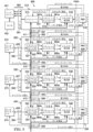
図5は、直列連鎖バスユニットの間で、システムウェイクアップ信号を生成し、転送するように適合された少なくとも1つのバスユニットを含む例示のシステムのブロック図である。例えば、システム500は例示のシステムであり、ヘッドユニット401(例えば、センサ402に結合される)、第1のバスユニット510(例えば、ローカルポート561及びケーブル560を介してヘッドユニット401に局地的に結合される)、第2のバスユニット520(例えば、ローカルポート562及びケーブル405を介してタッチディスプレイ572に局地的に結合される)、第3のバスユニット530(例えば、ローカルポート563及びケーブル407を介してタッチディスプレイ573に局地的に結合される)、及び第4のバスユニット540(例えば、ローカルポート564及びケーブル409を介してタッチディスプレイ574に局地的に結合される)を含む。バスユニット510、520、530、及び540は、(例えば、アップストリームで毎秒165メガビット又はダウンストリームで毎秒13ギガビットで)データを双方向に伝送するように適合され得る。バスユニット520、530、及び540は、シリアライザ及び/又はデシリアライザ(例えば、SERDES)及び/又はディスアグリゲータ(それぞれ、420、430、及び440等)であり得る。
5 is a block diagram of an example system including at least one bus unit adapted to generate and transfer a system wake-up signal between serially chained bus units. For example,
本明細書において、これ以降に概して説明される例示のウェイクアップシーケンスにおいて、第2のバスユニット520は、タッチディスプレイ572において検出されるウェイクアップ事象に応答して生成されるローカルウェイクアップ信号によって、節電モードからアクティブモード(例えば、アウェイクンド)で構成され得る。ローカルウェイクアップ信号に応答し、第2のバスユニット520は、システムウェイクアップ信号を生成し、第1のバスユニット510に送信し得る(例えば、その結果、システムウェイクアップ信号がアップストリーム方向に送信され、それに応答して、第1のバスユニット510がアウェイクされる)。同様に、第2のバスユニット520は、システムウェイクアップ信号を生成し、第3のバスユニット530に送信し得る(例えば、その結果、システムウェイクアップ信号がダウンストリーム方向に送信され、それに応答して、第3のバスユニット5がアウェイクされる)。この例において、第3のバスユニット530は、システムウェイクアップ信号の受信に応答して、その後のウェイクアップ信号を生成し、そのウェイクアップ信号を第4のバスユニット540に送信し得る(例えば、その結果、システムウェイクアップ信号がダウンストリーム方向に送信され、それに応答して、第3のバスユニット530がアウェイクされる)。その他のウェイクアップシーケンスは(例えば、図8、図9、及び図10に関連して)これ以降に説明される。
In an example wake-up sequence generally described hereinafter, the
第1の例示のシステムにおいて、システム500は、第1のバスユニット(FBU)510を含み、FBU510は、第1のシステムポート(例えば、ダウンストリームD-ポート591)と、FBUローカルポート(例えば、ローカルL-ポート561)と、FBUウェイクアップ入力と、FBUトランシーバ512と、FBUコントローラ514と、FBUエネルギー検出器516とを有する。FBUトランシーバ512は、FBU第1のシステムポート、FBUローカルポート、及びFBUウェイクアップ入力に結合される。
In a first exemplary system, the
FBU第1のシステムポート(例えば、591)は、FBU第1のシステム入力信号を受信するように適合される。FBUローカルポート(例えば、561)は、FBUローカル入力信号を受信するように適合される。FBUトランシーバ512は、FBU第1のシステム入力信号のデータを、FBU第1のモード(例えば、アクティブモード)で、FBUローカルポート(例えば、561)に伝送するように構成される。FBUトランシーバ512は、FBU第2のモードで節電するように構成される。FBUトランシーバ512は、FBUローカルウェイクアップ信号に応答して、FBU第1のモードに入るように構成される。FBUトランシーバ512は、FBUローカルウェイクアップ信号に応答して、FBU第1のシステムポート(例えば、591)及びFBUローカルポート(例えば、561)の1つにおいて、FBUシステムウェイクアップ信号を送信するように構成される。
The FBU first system port (e.g., 591) is adapted to receive the FBU first system input signal. The FBU local port (e.g., 561) is adapted to receive the FBU local input signal. The
FBUコントローラ514は、FBUエネルギー検出入力及びFBUウェイクアップ出力を有し、FBUウェイクアップ出力は、FBUウェイクアップ入力に結合される。FBUコントローラ514は、FBUエネルギー検出信号に応答して、FBUウェイクアップ出力において、FBUローカルウェイクアップ信号を生成するように構成される。
The
FBUエネルギー検出器516は、FBUエネルギー検出入力に結合されるFBUエネルギー検出出力を有する。FBUエネルギー検出器516は、FBU第1のシステムポート(例えば、バス551を介して)及びFBUローカルポートに(例えば、ノード561aを介して)結合される。FBUエネルギー検出器516は、FBU第2のモードでFBUトランシーバ512によって受信されるFBU第1のシステム入力信号(例えば、ノード561aを介して)及びFBUローカル入力信号の一方のエネルギーのFBU検出に応答して、FBUエネルギー検出出力においてFBUエネルギー検出信号を生成するように構成される。
The
第1の例示のシステムにおいて、システム500は更に、第2のバスユニット(SBU)第1のシステムポート(例えば、アップストリームU-ポート582)を有するSBU520を含む。SBU第1のシステムポートは、FBU第1のシステムポート(例えば、ダウンストリームD-ポート591)に結合される。SBU第1のシステムポート(例えば、582)は、FBUシステムウェイクアップ信号を受信するように適合され、FBU第1のシステムポート(例えば、591)は、SBUシステムウェイクアップ信号(例えば、SBU第1のシステムポートを介してSBU520によって送信される場合)を受信するように適合される。
In the first exemplary system, the
SBU520は更に、SBU第2のシステムポート(例えば、ダウンストリームD-ポート592)、SBUローカルポート(例えば、ローカルL-ポート562)、SBUウェイクアップ入力、SBUトランシーバ522、SBUコントローラ524、及びSBUエネルギー検出器526を含み得る。SBUトランシーバ522は、SBU第1のシステムポート、SBU第2のシステムポート、SBUローカルポート、及びSBUウェイクアップ入力に結合される。
The
SBU第1のシステムポート(例えば、582)は、SBU第1のシステム入力信号を受信するように適合され、SBU第2のシステムポート(例えば、592)は、SBU第2のシステム入力信号を受信するように適合され、SBUローカルポート(例えば、562)は、SBUローカル入力信号を受信するように適合される。SBUトランシーバ522は、SBU第1のモード(例えば、アクティブモード)で、SBU第1のシステム入力信号のデータをSBU第2のシステムポート(例えば、592)に伝送するように構成され、SBUトランシーバ522は、SBU第2のモード(例えば、節電モード)で、節電するように構成される。SBUトランシーバ522は、SBUローカルウェイクアップ信号に応答して、SBU第1のモードに入るように構成される。SBUトランシーバ522は、SBUローカルウェイクアップ信号に応答して、SBU第1のシステムポート及びSBU第2のシステムポートの一方において、SBUシステムウェイクアップ信号を送信するように構成される。
The SBU first system port (e.g., 582) is adapted to receive an SBU first system input signal, the SBU second system port (e.g., 592) is adapted to receive an SBU second system input signal, and the SBU local port (e.g., 562) is adapted to receive an SBU local input signal. The
概して、SBU520は、第1のシステムポート(例えば、582)、SBU第2のシステムポート(例えば、592)、及びSBUローカルポート(例えば、562)の任意のものにおけるウェイクアップ信号を検出し得る。SBU520は、(検出されたウェイクアップ信号に応答して)検出されたウェイクアップ信号を受け取ったポートに送信されるべき後続のウェイクアップ信号を生成するように構成される。第1のシナリオにおいて、SBUローカルポート(例えば、562)を介してウェイクアップ信号が検出され、それに応答して、SBUトランシーバ522は、SBU第1のシステムポート(例えば、582)を介し、SBU第2のシステムポート(例えば、592)を介して、システムウェイクアップ信号を送信する。第2のシナリオにおいて、SBU第1のシステムポート(例えば、582)を介してウェイクアップ信号が検出され、それに応答して、SBUトランシーバ522は、SBU第2のシステムポート(例えば、592)を介してシステムウェイクアップ信号を送信し、SBUローカルポート(例えば、562)を介してローカルウェイクアップ信号を送信する。第3のシナリオにおいて、SBU第2のシステムポート(例えば、592)を介してウェイクアップ信号が検出され、それに応答して、SBUトランシーバ522は、SBU第1のシステムポート(例えば、582)を介してシステムウェイクアップ信号を送信し、SBUローカルポート(例えば、562)を介してローカルウェイクアップ信号を送信する。SBU522がFBU510又は第3のバスユニット530の一方からシステムウェイクアップ信号を受信することに応答して、タッチディスプレイ572にローカルウェイクアップ信号を送信することが、節電モードからアクティブモードへ変換するようにタッチディスプレイに信号を送り得る。
In general, the
SBUコントローラ524は、SBUエネルギー検出入力及びSBUウェイクアップ出力を有し、SBUウェイクアップ出力は、SBUウェイクアップ入力に結合される。SBUコントローラ524は、SBUエネルギー検出信号に応答して、SBUウェイクアップ出力においてSBUローカルウェイクアップ信号を生成するように構成される。
The
SBUエネルギー検出器526は、SBUエネルギー検出入力に結合されるSBUエネルギー検出出力を有する。SBUエネルギー検出器526は、SBU第1のシステムポート(例えば、582)、SBU第2のシステムポート(例えば、592)及びSBUローカルポート(例えば、562)に結合される。SBUエネルギー検出器526は、SBU第2のモードで、SBUトランシーバ522によって受信される、SBU第1のシステム入力信号(例えば、ノード582aを介して)、SBU第2のシステム入力信号(例えば、バス552を介して)、及びSBUローカル入力信号(例えば、ノード562aを介して)のうちの1つのエネルギーのSBU検出に応答して、SBUエネルギー検出出力においてSBUエネルギー検出信号を生成するように構成される。
The
第1の例示のシステムにおいて、システム500は更に第3のバスユニット(TBU)530を含み、TBU530は、TBU第1のシステムポート(例えば、アップストリームU-ポート583)、任意選択のTBU第2のシステムポート(例えば、ダウンストリームD-ポート593)、TBUローカルポート(例えば、ローカルL-ポート563)、TBUウェイクアップ入力、TBUトランシーバ532、TBUコントローラ534、及びTBUエネルギー検出器536を有する。TBU第1のシステムポート(例えば、583)は、SBU第2のシステムポート(例えば、592)に結合される。TBUトランシーバ532は、TBU第1のシステムポート、任意選択のTBU第2のシステムポート、TBUローカルポート、及びTBUウェイクアップ入力に結合される。
In the first exemplary system, the
TBU第1のシステムポート(例えば、583)は、TBU第1のシステム入力信号を受信するように適合され、任意選択のTBU第2のシステムポート(例えば、593)は、TBU第2のシステム入力信号を受信するように適合され得、TBUローカルポート(例えば、563)は、TBUローカル入力信号を受信するように適合される。TBUトランシーバ532は、TBU第1のモード(例えば、アクティブモード)で、TBU第1のシステム入力信号のデータをTBUローカルポート(例えば、563)及びTBU第2のシステムポート(例えば、593)の一方に伝送するように構成され、TBUトランシーバ532は、TBU第2のモード(例えば、節電モード)で節電するように構成される。TBUトランシーバ532は、TBUローカルウェイクアップ信号に応答して、TBU第1のモードに入るように構成される。TBUトランシーバ532は、TBUローカルウェイクアップ信号に応答して、TBU第1のシステムポート及びTBUローカルポートの一方において、TBUシステムウェイクアップ信号を送信するように構成される。SBU第2のシステムポート(例えば、592)は、(例えば、TBUシステムウェイクアップ信号がTBU第1のシステムポートを介してTBU530によって送信されたことに応答して)、TBUシステムウェイクアップ信号を受信するように適合される。
The TBU first system port (e.g., 583) is adapted to receive the TBU first system input signal, the optional TBU second system port (e.g., 593) may be adapted to receive the TBU second system input signal, and the TBU local port (e.g., 563) is adapted to receive the TBU local input signal. The
概して、TBU530は、第1のシステムポート(例えば、583)、TBU第2のシステムポート(例えば、593)、及びTBUローカルポート(例えば、563)の任意のものにおけるウェイクアップ信号を検出し得る。TBU530は、(検出されたウェイクアップ信号に応答して)、検出されたウェイクアップ信号が受信されたポートに送信されるべき後続のウェイクアップ信号を生成するように構成される。第1のシナリオにおいて、TBUローカルポート(例えば、563)を介してウェイクアップ信号が検出され、それに応答して、TBUトランシーバ532は、システムウェイクアップ信号を、TBU第1のシステムポート(例えば、583)を介し、TBU第2のシステムポート(例えば、593)を介して送信する。第2のシナリオにおいて、TBU第1のシステムポート(例えば、583)を介してウェイクアップ信号が検出され、それに応答して、TBUトランシーバ532は、TBU第2のシステムポート(例えば、593)を介してシステムウェイクアップ信号を送信し、TBUローカルポート(例えば、563)を介してローカルウェイクアップ信号を送信する。第3のシナリオにおいて、TBU第2のシステムポート(例えば、593)を介してウェイクアップ信号が検出され、それに応答して、TBUトランシーバ532は、TBU第1のシステムポート(例えば、583)を介してシステムウェイクアップ信号を送信し、TBUローカルポート(例えば、563)を介してローカルウェイクアップ信号を送信する。TBU532がSBU510又は第3のバスユニット530の一方からシステムウェイクアップ信号を受信することに応答して、ローカルウェイクアップ信号をタッチディスプレイ573に送信することが、タッチディスプレイに節電モードからアクティブモードに変換させるように信号を送り得る(例えば、命令し得る)。
In general, the
TBUコントローラ534は、TBUエネルギー検出入力及びTBUウェイクアップ出力を有し、TBUウェイクアップ出力は、TBUウェイクアップ入力に結合される。TBUコントローラ534は、TBUエネルギー検出信号に応答して、TBUウェイクアップ出力においてTBUウェイクアップ信号を生成するように構成される。
The
TBUエネルギー検出器536は、TBUエネルギー検出入力に結合されるTBUエネルギー検出出力を有する。TBUエネルギー検出器536は、TBU第1のシステムポート(例えば、583)、TBU第2のシステムポート(例えば、593)、及びTBUローカルポート(例えば、563)に結合される。TBUエネルギー検出器536は、TBU第2のモードでTBUトランシーバ532によって受信される、TBU第1のシステム入力信号(例えば、ノード583aを介して)、任意選択のTBU第2のシステム入力信号(例えば、バス553を介して)、及びTBUローカル入力信号(例えば、ノード563aを介して)のうちの1つのエネルギーのTBU検出に応答して、TBUエネルギー検出出力にいて、TBUエネルギー検出信号を生成するように構成される。
The
第1の例示のシステムにおいて、システム500は更に、直列連鎖のシステムバスを延長するための、付加的な(例えば、任意選択の)バスユニットを含み得る。例えば、第4のバスユニット540は、第1のシステムポート(例えば、アップストリームU-ポート584)、第2のシステムポート(例えば、ダウンストリームD-ポート594)、ローカルポート(例えば、ローカルL-ポート564)、ウェイクアップ入力、トランシーバ542、コントローラ544、及びエネルギー検出器546を有する。第1のシステムポート(例えば、584)は、TBU第2のシステムポート(例えば、593)に結合される。
In the first exemplary system, the
第1のシステムポート(例えば、584)は、第1のシステム入力信号を受信するように適合され、任意選択の第2のシステムポート(例えば、594)は、第2のシステム入力信号を受信するように適合され得、ローカルポート(例えば、564)は、ローカル入力信号を受信するように適合される。トランシーバ542は、第1のモード(例えば、アクティブモード)で、第1のシステム入力信号のデータを、ローカルポート(例えば、564)及び第2のシステムポート(例えば、594)のうちの1つに伝送するように構成され、トランシーバ542は、第2のモード(例えば、節電モード)で節電するように構成される。トランシーバ542は、ローカルウェイクアップ信号に応答して、第1のモードに入るように構成される。トランシーバ542は、ローカルウェイクアップ信号に応答して、第1のシステムポート及びローカルポートのうちの1つにおいて、システムウェイクアップ信号を送信するように構成される。TBU第2のシステムポート(例えば、593)は、(例えば、第4のバスユニットシステムウェイクアップ信号が第4のバスユニットの第1のシステムポートを介して第4のバスユニット540によって送信されたことに応答して)第4のバスユニット生成システムウェイクアップ信号を受信するように適合される。
The first system port (e.g., 584) is adapted to receive a first system input signal, the optional second system port (e.g., 594) may be adapted to receive a second system input signal, and the local port (e.g., 564) is adapted to receive a local input signal. The
コントローラ544は、エネルギー検出入力及びウェイクアップ出力を有し、ウェイクアップ出力はウェイクアップ入力に結合される。コントローラ544は、エネルギー検出信号に応答して、ウェイクアップ出力においてローカルウェイクアップ信号を生成するように構成される。
The
エネルギー検出器546は、エネルギー検出入力に結合されるエネルギー検出出力を有する。エネルギー検出器546は、第1のシステムポート(例えば、584)、第2のシステムポート(例えば、594)、及びローカルポート(例えば、564)に結合される。エネルギー検出器546は、第2のモードでトランシーバ542によって受信される、第1のシステム入力信号(例えば、ノード584aを介して)、任意選択の第2のシステム入力信号(例えば、バス554を介して)、及びローカル入力信号(例えば、ノード564aを介して)のうちの1つのエネルギーの検出に応答して、エネルギー検出出力においてエネルギー検出信号を生成するように構成される。
The
第1の例示のシステムにおいて、システム500は更に、タッチディスプレイ572、573、及び574の1つ等の、ユーザインタフェース(UI)デバイスを含む。タッチディスプレイ572は、ケーブル405及びローカルポート562を介してSBU520のトランシーバ522のスイッチ527(例えば、スイッチ427と同様)に結合され、タッチディスプレイ573は、ケーブル407及びローカルポート563を介してTBU530のトランシーバ532のスイッチ537(例えば、スイッチ437と同様)に結合され、タッチディスプレイ574は、ケーブル409及びローカルポート564を介して第4のバスユニット540のトランシーバ542のスイッチ547(例えば、スイッチ447と同様)に結合される。
In the first exemplary system, the
FBU510に関して、UIデバイス(例えば、センサ402及びヘッドユニット401)が、FBUローカルポート(561)に結合されるUIポート(例えば、560)を含み、UIデバイスは、ユーザ入力(ユーザのタッチ、ユーザの音声、ユーザの操作、近接検出、及び物理的又は電子的指示等)を受け取るように適合される。FBU510は、ユーザ入力に応答して、UIポートにおいてユーザウェイクアップ信号を生成するように構成される。FBU510は、ユーザウェイクアップ信号に応答して、SBUシステムウェイクアップ信号を生成するように構成される。SBU520は、FBUシステムウェイクアップ信号に応答して、SBUローカルウェイクアップ信号を生成するように構成される。
With respect to the
SBU520に関して、UIデバイス(例えば、タッチディスプレイ572)が、SBUローカルポート(562)に結合されるUIポート(例えば、405)を含み、UIデバイスは、ユーザ入力を受け取るように適合される。SBU520は、ユーザ入力に応答して、UIポートにおいてユーザウェイクアップ信号を生成するように構成される。SBU520は、ユーザウェイクアップ信号に応答して、SBUシステムウェイクアップ信号を生成するように構成される。FBU510は、SBUシステムウェイクアップ信号に応答して、FBUローカルウェイクアップ信号を生成するように構成され、TBU530は、SBUシステムウェイクアップ信号に応答して、FBUローカルウェイクアップ信号を生成するように構成される。
With respect to the
TBU530に関して、UIデバイス(例えば、タッチディスプレイ573)が、TBUローカルポート(563)に結合されるUIポート(例えば、407)を含み、UIデバイスは、ユーザ入力を受け取るように適合される。TBU530は、ユーザ入力に応答して、UIポートにおいてユーザウェイクアップ信号を生成するように構成される。TBU530は、ユーザウェイクアップ信号に応答して、TBUシステムウェイクアップ信号を生成するように構成される。SBU520は、TBUシステムウェイクアップ信号に応答して、SBUローカルウェイクアップ信号を生成するように構成され、第4のバスユニット540は、TBUシステムウェイクアップ信号に応答して、第4のバスユニットのローカルウェイクアップ信号を生成するように構成される。
With respect to the
第4のバスユニット540に関して、UIデバイス(例えば、タッチディスプレイ574)が、第4のバスユニットのローカルポート(564)に結合されるUIポート(例えば、409)を含み、UIデバイスはユーザ入力を受け取るように適合される。第4のバスユニット540は、ユーザ入力に応答して、UIポートにおいてユーザウェイクアップ信号を生成するように構成される。第4のバスユニット540は、ユーザウェイクアップ信号に応答して、第4のバスユニットシステムウェイクアップ信号を生成するように構成される。TBU530は、第4のバスユニットシステムウェイクアップ信号に応答して、TBUローカルウェイクアップ信号を生成するように構成され、任意の直列連鎖の付加的なバスユニットが、近接する直列連鎖のバスユニットシステムウェイクアップ信号に応答して、それぞれのユニットのローカルウェイクアップ信号を生成するように構成される。
For the
第2の例示のシステムにおいて、システム500は電力管理システム508を含む。電力管理システム508は、FBU510に結合されるPMIC(電力マネージャ集積回路)518、SBU520に結合されるPMIC528、TBU520に結合されるPMIC538、及び第4のバスユニット540に結合されるPMIC548等の電力マネージャを含む。PMIC518、PMIC528、PMIC538、及びPMIC548は、共通の基板上に含まれ得、それぞれのPMIC及び/又はそれらの組み合わせが結合されるバスユニットを含む基板上に含まれ得る。例えば、電力マネージャ及びエネルギー検出回路要素の制御を動作させるための電力が、VDDKA(第1の電力レールキープアライブ)電力信号(これは、例えば、節電モードにおいて、電力消費を低減させる)を介して提供(例えば、結合され)され得る。
In a second exemplary system, the
第2の例示のシステムにおいて、システム500は、トランシーバ(例えば、522)、コントローラ(例えば、524)、及びエネルギー検出器(例えば、526)を含む回路(SBU520等)を含む。
In a second exemplary system, the
トランシーバ(例えば、522)は、第1のシステムポート(例えば、582及び592のうちで第1に選択されたもの)、第2のシステムポート(例えば、582及び592のうちで第2に選択されたもので、これは582及び592のうちで第1に選択されたものとは異なる)、ローカルポート(例えば、562)、及びウェイクアップ入力を有する。第1のシステムポートは、第1のシステム入力信号を受信するように適合され、第2のシステムポートは、第2のシステム入力信号を受信するように適合され、ローカルポートは、ローカル入力信号を受信するように適合される。トランシーバは、第1のモードで第1のシステム入力信号のデータを第2のシステムポートに伝送するように構成され、トランシーバは、第2のモードで節電するように構成され、トランシーバは、ローカルウェイクアップ信号に応答して、第1のモードに入るように構成され、トランシーバは、ローカルウェイクアップ信号に応答して第2のシステムポートにおいてシステムウェイクアップ信号を送信するように構成される。 The transceiver (e.g., 522) has a first system port (e.g., a first selected one of 582 and 592), a second system port (e.g., a second selected one of 582 and 592, which is different from the first selected one of 582 and 592), a local port (e.g., 562), and a wake-up input. The first system port is adapted to receive a first system input signal, the second system port is adapted to receive a second system input signal, and the local port is adapted to receive a local input signal. The transceiver is configured to transmit data of the first system input signal to the second system port in a first mode, the transceiver is configured to save power in a second mode, the transceiver is configured to enter the first mode in response to a local wake-up signal, and the transceiver is configured to transmit a system wake-up signal at the second system port in response to the local wake-up signal.
コントローラ(例えば、524)は、エネルギー検出入力及びウェイクアップ出力を有し、ウェイクアップ出力はウェイクアップ入力に結合される。コントローラは、エネルギー検出信号に応答して、ウェイクアップ出力においてローカルウェイクアップ信号を生成するように構成される。 The controller (e.g., 524) has an energy detect input and a wake-up output, the wake-up output being coupled to the wake-up input. The controller is configured to generate a local wake-up signal at the wake-up output in response to the energy detect signal.
エネルギー検出器(例えば、526)は、エネルギー検出入力に結合されるエネルギー検出出力を有する。エネルギー検出器は、第1のシステムポート及びローカルポートに結合される。エネルギー検出器は、第2のモードで、トランシーバによって受信される第1のシステム入力信号及びローカル入力信号の一方のエネルギーの検出に応答して、エネルギー検出出力においてエネルギー検出信号を生成するように構成される。 An energy detector (e.g., 526) has an energy detect output coupled to the energy detect input. The energy detector is coupled to the first system port and the local port. The energy detector is configured to generate an energy detect signal at the energy detect output in response to detecting energy in one of the first system input signal and the local input signal received by the transceiver in the second mode.
一例において、トランシーバは更に、第1のモードで、第2のシステム入力信号のデータを第1のシステムポートに伝送するように構成される。この例において、システムウェイクアップ信号はウェイクアップパターンを含み得る。 In one example, the transceiver is further configured to transmit data of the second system input signal to the first system port in the first mode. In this example, the system wake-up signal may include a wake-up pattern.
別の例において、トランシーバは更に、第2のモードで、ローカルウェイクアップ信号に応答して、第1のシステムポートにおいてシステムウェイクアップ信号を送信するように構成される。 In another example, the transceiver is further configured in the second mode to transmit a system wake-up signal at the first system port in response to the local wake-up signal.
更に別の例において、エネルギー検出器は、第1のシステム入力信号及びローカル入力信号の一方のエネルギーを検出するように構成される。この例において、エネルギー検出器は、第2のシステムポートに結合され得、エネルギー検出器は、第2のシステム入力信号のエネルギーを検出するように構成され得る。この例において、エネルギー検出器は、第2のモードで、トランシーバによって受信される第2のシステム入力信号のエネルギーの検出に応答して、エネルギー検出出力において、エネルギー検出信号を生成するように構成される。 In yet another example, the energy detector is configured to detect energy in one of the first system input signal and the local input signal. In this example, the energy detector may be coupled to the second system port, and the energy detector may be configured to detect energy in the second system input signal. In this example, the energy detector is configured to generate an energy detection signal at the energy detection output in response to detecting energy in the second system input signal received by the transceiver in the second mode.
更なる例において、コントローラは更に、第1のシステムポート及びローカルポートに結合される。コントローラは更に、エネルギー検出信号に応答して、第1のシステム入力信号及びローカル入力信号の1つにおいて、ウェイクアップパターンを検出するように構成される。この例では、コントローラは更に、データ有効出力を含み得、コントローラは、第1のシステム入力信号及びローカル入力信号の1つにおけるウェイクアップパターンの検出に応答して、データ有効出力においてデータ有効信号を生成するように構成される。この例では、エネルギー検出器は更に、データ有効入力及びイネーブル電力出力を含み得、データ有効入力はデータ有効出力に結合され、エネルギー検出器は更に、イネーブル電力出力においてイネーブル電力信号を生成するように構成される。この例では、回路は更に電力マネージャを含み得、電力マネージャはイネーブル電力入力及び電力供給出力を含み、イネーブル電力入力はイネーブル電力出力に結合され、電力マネージャは、イネーブル電力信号に応答して、電力供給出力において電力信号を生成するように構成される。この例では、コントローラは更に、電力供給入力を含み、電力供給入力は電力供給出力に結合され、コントローラは更に、電力信号に応答してローカルウェイクアップ信号を生成するように構成される。例示のシステムにおいて、電力マネージャの回路は更に、ロジックイネーブル出力を含み得、コントローラは更にロジックイネーブル入力を含み得、ロジックイネーブル入力はロジックイネーブル出力に結合され、電力マネージャは更に、電力信号に応答して、ロジックイネーブル出力においてロジックイネーブル信号を生成するように構成され得、コントローラは更に、ロジックイネーブル信号に応答してローカルウェイクアップ信号を生成するように構成され得る。 In a further example, the controller is further coupled to the first system port and the local port. The controller is further configured to detect a wake-up pattern in one of the first system input signal and the local input signal in response to the energy detect signal. In this example, the controller may further include a data valid output, and the controller is configured to generate a data valid signal at the data valid output in response to detecting the wake-up pattern in one of the first system input signal and the local input signal. In this example, the energy detector may further include a data valid input and an enable power output, and the data valid input is coupled to the data valid output, and the energy detector is further configured to generate an enable power signal at the enable power output. In this example, the circuit may further include a power manager, and the power manager includes an enable power input and a power supply output, and the enable power input is coupled to the enable power output, and the power manager is configured to generate a power signal at the power supply output in response to the enable power signal. In this example, the controller further includes a power supply input, and the power supply input is coupled to the power supply output, and the controller is further configured to generate a local wake-up signal in response to the power signal. In an example system, the power manager circuitry may further include a logic enable output, and the controller may further include a logic enable input, the logic enable input coupled to the logic enable output, the power manager may further be configured to generate a logic enable signal at the logic enable output in response to the power signal, and the controller may further be configured to generate a local wake-up signal in response to the logic enable signal.
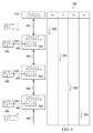
図6は、図5の例示のシステムのウェイクアップ信号発行の例示の方法のフローチャートである。例示の方法600は、本明細書においてこれ以降に説明する種々の技法を含み得る。種々の実装において、説明される動作は必ずしも説明される順に実施される必要はない。例示の方法600において、方法は605において開始され得る。
6 is a flow chart of an example method of issuing a wake-up signal for the example system of FIG. 5. The
605において、この方法は、第1のバスユニット(FBU)の第1のポートによって、第1のウェイクアップ信号を受信することを含み得る。例えば、センサ502に応答して、ヘッドユニット401によって第1のウェイクアップ信号が生成され得る。第1のウェイクアップ信号は、ローカルポート561において、FBU510によって受信され得る。この方法は610において継続し得る。
At 605, the method may include receiving a first wake-up signal by a first port of a first bus unit (FBU). For example, the first wake-up signal may be generated by
610において、この方法は、第1のウェイクアップ信号に応答して、FBUの第2のポートに電力を印加することを含み得る。例えば、PMIC518等の電力管理回路要素は、動作電力を、(例えば、トランシーバ512の)トランスミッタに結合し得、その結果、トランスミッタは、節電モードを出てアクティブモードに入り得る(例えば、そこでは、信号が送信され得る)。一例において、電力は、電源を付勢することによって結合され得る。別の例において、システムクロックが起動され(例えば、発行され)、その結果、アクティブなCMOS回路要素のスイッチングが、起動されたシステムクロックによって切り替えられることに応答して、付加的な電力が引かれる。或る実装において、受信されたウェイクアップ信号に応答して、全てのバスユニットのアクティブな回路要素に対して電力を印加することによって、全体のバスユニットがアクティブモードに置かれ得る。この方法は615において継続し得る。
At 610, the method may include applying power to a second port of the FBU in response to the first wake-up signal. For example, a power management circuit element, such as the
615において、この方法は、第1のウェイクアップ信号に応答して、FBUの第2のポートによって、第2のウェイクアップ信号を送信することを含み得る。例えば、トランシーバ512のトランスミッタ部分が、第2のポート(例えば、第1のシステムポート591)から第2のウェイクアップ信号を送信し得る。この方法は620において継続し得る。
At 615, the method may include transmitting a second wake-up signal by a second port of the FBU in response to the first wake-up signal. For example, a transmitter portion of the
620において、この方法は、第2のバスユニット(SBU)の第1のポートによって、第2のウェイクアップ信号を受信することを含み得る。例えば、第2のウェイクアップ信号は、第1のウェイクアップ信号に応答して、FBU510によって生成され得る。第2のウェイクアップ信号は、第1のシステムポート582において、SBU520によって受信され得る。この方法は625において継続し得る。
At 620, the method may include receiving a second wake-up signal by a first port of a second bus unit (SBU). For example, the second wake-up signal may be generated by the
625において、この方法は、第2のウェイクアップ信号に応答して、SBUの第2のポートに電力を印加することを含み得る。例えば、PMIC528等の電力管理回路要素が、動作電力をトランスミッタ(例えば、トランシーバ522)に結合し得、その結果、トランスミッタは、節電モードから出てアクティブモードに入り得る(例えば、そこでは信号が送られ得る)。この方法は630において継続し得る。
At 625, the method may include applying power to a second port of the SBU in response to the second wake-up signal. For example, power management circuitry such as
630において、この方法は、第2のウェイクアップ信号に応答して、SBUの第2のポートによって、第3のウェイクアップ信号を送信することを含み得る。例えば、トランシーバ522のトランスミッタ部分が、第2のポート(例えば、第2のシステムポート592)から第3のウェイクアップ信号を送信し得る。トランシーバ522のトランスミッタ部分が、第2のウェイクアップ信号に応答して、ローカルウェイクアップ信号を、第3のポート(例えば、562)から、局地的に結合されたデバイス(例えば、タッチディスプレイ572)に任意選択的に送り得る。この方法は635において継続し得る。
At 630, the method may include transmitting a third wake-up signal by a second port of the SBU in response to the second wake-up signal. For example, the transmitter portion of the
635において、この方法は、第3のバスユニット(TBU)の第1のポートによって、第3のウェイクアップ信号を受信することを含み得る。例えば、第3のウェイクアップ信号は、第2のウェイクアップ信号に応答して、SBU520によって生成され得る。第3のウェイクアップ信号は、第1のシステムポート582において、TBU530によって受信され得る。この方法は625において継続し得る。
At 635, the method may include receiving a third wake-up signal by a first port of a third bus unit (TBU). For example, the third wake-up signal may be generated by
640において、この方法は、第3のウェイクアップ信号に応答して、電力をTBUに印加することを含み得る。例えば、PMIC538等の電力管理回路要素は、動作電力をTBU530に結合し得、その結果、TBU530は節電モードから出てアクティブモードに入り得る(例えば、そこでは信号がアクティブに受信及び送信され得る)。このように、本明細書に説明されるシステム500において、ローカルウェイクアップ事象が、バスユニットの直列連鎖を横断し通過して発行され得る。
At 640, the method may include applying power to the TBU in response to the third wake-up signal. For example, power management circuitry such as the
図7は、図5の例示のシステムのウェイクアップ信号検出及びウェイクアップ信号処理の例示の方法のフローチャートである。例示の方法700は、本明細書においてこれ以降に説明する種々の技法を含み得る。種々の実装において、説明される動作は必ずしも説明された順に実施される必要はない。例示の方法700において、この方法は705において開始され得る。
7 is a flow chart of an example method of wake-up signal detection and wake-up signal processing for the example system of FIG. 5. The
705において、この方法は、エネルギー検出器(例えば、526)によって、ウェイクアップモード信号を監視することを含み得る。例えば、ウェイクアップモード信号は、動作電力をバスユニットのエネルギー検出器に供給し得るVDDKA信号であり得る。この方法は710において継続し得る。 At 705, the method may include monitoring, by an energy detector (e.g., 526), for a wake-up mode signal. For example, the wake-up mode signal may be a VDDKA signal that may provide operating power to the energy detector of the bus unit. The method may continue at 710.
710において、ウェイクアップモード信号がアサートされた場合、この方法は715において継続し、そうでない場合、この方法は705において継続する。 If the wake-up mode signal is asserted at 710, the method continues at 715, otherwise the method continues at 705.
715において、この方法は、エネルギー検出器(例えば、526)によって、信号エネルギーについて入力信号を監視することを含み得る。例えば、バスユニットのエネルギー検出器は、導電体によって搬送される電界強度、電流、及び/又は電圧レベルを閾値に対して比較して入力信号における量子化された変化を検出し得る。信号網(例えば、信号線)は、専用ウェイクアップ信号導体であり得、或いは、バスユニットがアクティブモードで動作している間は他の目的(例えば、アップストリームソースからビデオストリーム情報を受け取るための信号レーン)に用いられ得る。この方法は720において継続し得る。 At 715, the method may include monitoring the incoming signal for signal energy by an energy detector (e.g., 526). For example, the energy detector of the bus unit may compare the field strength, current, and/or voltage levels carried by the conductors against a threshold to detect quantized changes in the incoming signal. The signal network (e.g., signal lines) may be dedicated wake-up signal conductors or may be used for other purposes (e.g., signal lanes for receiving video stream information from an upstream source) while the bus unit is operating in the active mode. The method may continue at 720.
720において、信号エネルギーが検出される場合、この方法は725において継続し、そうでない場合、この方法は705において継続する。 If signal energy is detected at 720, the method continues at 725, otherwise the method continues at 705.
725において、この方法は、信号エネルギーの検出に応答して、エネルギー検出器(例えば、526)によってイネーブル電力信号をアサートすることを含み得る。この方法は730において継続する。 At 725, the method may include asserting an enable power signal by an energy detector (e.g., 526) in response to detecting the signal energy. The method continues at 730.
730において、この方法は、信号エネルギーの検出に応答して、エネルギー検出器(例えば、526)によって、エネルギー検出信号をアサートすることを含み得る。この方法は735において継続する。 At 730, the method may include asserting, by an energy detector (e.g., 526), an energy detect signal in response to detecting the signal energy. The method continues at 735.
735において、この方法は、アサートされたイネーブル電力信号に応答して、電力管理インタフェースコントローラ(例えば、528)によって、電力をバスユニットのコントローラ(例えば、524)に印加することを含み得る。この方法は740において継続する。 At 735, the method may include applying power to the bus unit's controller (e.g., 524) by a power management interface controller (e.g., 528) in response to the asserted enable power signal. The method continues at 740.
740において、この方法は、イネーブル電力信号に応答して、電力管理インタフェースコントローラ(例えば、528)によって、ロジックイネーブル信号をアサートすることを含み得る。例えば、ロジックイネーブル信号は、電力の印加後、コントローラのロジック回路が安定化し得る時間期間後にアサートされ得る。この方法は745において継続する。 At 740, the method may include asserting, by a power management interface controller (e.g., 528), a logic enable signal in response to the enable power signal. For example, the logic enable signal may be asserted after a period of time following application of power to allow logic circuitry of the controller to stabilize. The method continues at 745.
745において、この方法は、コントローラ(例えば、524)によって、有効検出期間の開始時間を判定することを含み得る。例えば、コントローラは、ロジックイネーブル信号に応答して、有効検出期間の開始時間を判定し得る(例えば、タイマーを開始する)。この有効検出期間の間に、入力信号(例えば、潜在的なウェイクアップ信号)が有効データ(例えば、ウェイクアップパターン)について評価される。この方法は750において継続する。 At 745, the method may include determining, by a controller (e.g., 524), a start time of a valid detection period. For example, the controller may determine a start time of a valid detection period (e.g., start a timer) in response to the logic enable signal. During this valid detection period, an input signal (e.g., a potential wake-up signal) is evaluated for valid data (e.g., a wake-up pattern). The method continues at 750.
750において、この方法は、バスユニットのコントローラ(例えば、524)によって、入力信号の受け取った信号を、有効データについて評価することを含み得る。例えば、入力信号は、ウェイクアップパターンの存在を判定するために評価され得る。有効データはまた、入力信号においてウェイクアップ信号が受信されたバスユニットを識別するように構成されたウェイクアップコードを含み得る。ウェイクアップパターンは、エントロピーを低減するため(例えば、注入されたノイズに起因する誤検知を低減するため)に符号化され得る。この方法は755において継続する。 At 750, the method may include evaluating, by a controller (e.g., 524) of the bus unit, a received signal of the input signal for valid data. For example, the input signal may be evaluated to determine the presence of a wake-up pattern. The valid data may also include a wake-up code configured to identify the bus unit from which the wake-up signal was received in the input signal. The wake-up pattern may be encoded to reduce entropy (e.g., to reduce false positives due to injected noise). The method continues at 755.
755において、この方法は、有効データが検出された場合は、780において継続し、検出されない場合は、この方法は760において継続する。 At 755, if valid data is detected, the method continues at 780; if not, the method continues at 760.
760において、この方法は、有効検出期間が満了した(例えば、有効検出期間を過ぎている)場合、765において継続し、そうでない場合、この方法は750において継続する。 At 760, if the valid detection period has expired (e.g., the valid detection period has passed), the method continues at 765, otherwise the method continues at 750.
765において、この方法は、バスユニットのコントローラ(例えば、524)によって、有効データが検出されなかったことを示すことを含み得る。この方法は770において継続する。 At 765, the method may include indicating, by the bus unit's controller (e.g., 524), that no valid data was detected. The method continues at 770.
770において、この方法は、有効データが検出されなかったことの指示に応答して、エネルギー検出器(例えば、526)によって、イネーブル電力信号をデアサートすることを含み得る。例えば、イネーブル電力信号は、アクティブロー信号(例えば、有効データ)を否定することによってデアサートされ得る。アクティブロー信号は、アクティブローのときに、有効データが検出されたことを示す。この方法は775において継続する。 At 770, the method may include deasserting, by the energy detector (e.g., 526), an enable power signal in response to an indication that valid data was not detected. For example, the enable power signal may be deasserted by negating an active low signal (e.g., valid data), which, when active low, indicates that valid data was detected. The method continues at 775.
775において、この方法は、デアサートされたイネーブル電力信号に応答して、電力管理インタフェースコントローラ(例えば、528)によって、バスユニットのコントローラ(例えば、524)から電力を除去することを含み得る。この方法は705において継続する。 At 775, the method may include removing power from the bus unit's controller (e.g., 524) by the power management interface controller (e.g., 528) in response to the deasserted enable power signal. The method continues at 705.
780において、この方法は、バスユニット(例えば、エネルギー検出器526及びコントローラ524を含む第1のバスユニットであるバスユニット520)によって、ウェイクアップ信号(例えば、第2のウェイクアップ信号)を別のバスユニット(例えば、バスユニット510及び/又は530等の第2のバスユニット)に送信することを含み得る。例えば、第1のバスユニットは、第2のウェイクアップ信号を第2のバスユニットに送り得、第2のウェイクアップ信号は、第1のバスユニットの識別子を用いて符号化され、第2のバスユニットは、第1のウェイクアップ信号が送られたバスユニットではない。ウェイクアップ信号は、繰り返しパターンを含み得、その結果、有効検出期間にわたってウェイクアップ信号が送信され(例えば、繰り返して送信され)得る。有効検出期間の長さ(例えば、持続期間)は、それぞれのバスユニットに対して選択され得る。一例において、ウェイクパターンが、3個の開始ビット「101」、4個のアドレスビット「0010」(これは、バスユニット520を示す)、及び偶数パリティビット「1」を含み、その結果、送信されたウェイクパターンは、8ビット「10100101」の繰り返し可能なパターンである。受け取ったパターンが正しいパリティビットを含まず、また開始ビット「101」を含まないとき、データ有効信号は、コントローラ524によって、デアサートされ(例えば、高に設定され)て、受け取ったウェイクパターンが有効ではないことを示し、その結果、エネルギー検出器526は、無効なウェイクパターンに応答して、イネーブル電力信号をアサートしない。
At 780, the method may include a bus unit (e.g., a
図8は、例示のシステムにおける第1の例示のウェイクアップ信号処理シナリオのブロック図である。この例において、システム800は、810、820、830、及び840等の直列連鎖バスユニットを含む。バスユニットは、デシリアライザ(これは、直列化回路及び非直列化回路自体の両方を含み得る)及び/又はディスアグリゲータ(図4に関連して上述されたもの)であり得る。
Figure 8 is a block diagram of a first example wake-up signal processing scenario in an example system. In this example,
FBU810は、マルチストリーム生成器410及び/又はFBU510と同様であり得る。FBU810は、種々のデバイス(例えば、センサ402及びヘッドユニット401)に、局地的に結合され得、任意の結合されたセンサによって生成された入力に応答して、ローカルウェイクアップ信号を生成し得る。FBU810は、SBU820のアップストリームである(例えば、システムバスの主チャネルにおけるビデオストリームフローの大部分の方向に関して)。FBU810は、ケーブル801を介してSBU820に結合される。ケーブル801(及びケーブル802、803、及び804の各々)は、ウェイクアップ信号の送信及び/又は受信のための導体(例えば、ツイストペア、同軸、又は光ファイバ)を含むケーブルハーネスであり得る。幾つかの例において、アクティブモードで、ビデオストリーミングのための「レーン」として確保された導体が、ウェイクアップ信号を、節電モードにある近接するバスユニットに送信するために用いられ得る。
The
FBU810は、ケーブル801を介して第2のバスユニット(SBU)820に結合される。SBU820は、ケーブル824を介して、タッチディスプレイ826(これはタッチディスプレイ572と同様であり得る)に局地的に結合され、SBU820が、アクティブモードでビデオをディスアグリゲートし(スイッチ822によって)、ディスアグリゲートされたストリームをタッチディスプレイ826に送るように構成される。SBU820は、ケーブル802を介して第3のバスユニット(TBU)830に結合される。TBU830は、ケーブル834を介して、タッチディスプレイ836(これはタッチディスプレイ573と同様であり得る)に局地的に結合され、TBU830は、アクティブモードでビデオをディスアグリゲートし(スイッチ832によって)、ディスアグリゲートされたストリームをタッチディスプレイ836に送るように構成される。TBU830は、ケーブル803を介して第4のバスユニット840に結合される。第4のバスユニット840は、ケーブル844を介してタッチディスプレイ846(これはタッチディスプレイ574と同様であり得る)に局地的に結合され、第4のバスユニット840は、アクティブモードでビデオをディスアグリゲートし(スイッチ842によって)、ディスアグリゲートされたストリームをタッチディスプレイ846に送るように構成される。第4のバスユニット840は、ケーブル804を介して、近接する(例えば、ダウンストリーム)バスユニットに結合され得る(更により多くのダウンストリームのバスユニットが、システムバスに沿って直列に連鎖され得、付加的なダウンストリームユニットの各々が、同様の回路に局地的に結合され得る)。
The
第1の例示のシナリオにおいて、第1のバスユニット(例えば、FBU810)が、ユーザウェイクアップ信号(例えば、センサ402及びヘッドユニット401によって生成される)に応答して、第1の時間(例えば、時間T0)において、システムウェイクアップ信号850を生成する(例えば、送信する)ように構成される。システムウェイクアップ信号850は、第1の出力(例えば、ケーブル801)において生成される。第2のバスユニット(例えば、SBU820)が、システムウェイクアップ信号850に応答して、第2の時間(例えば、第1の時間に続く時間T1)において、システムウェイクアップ信号851を生成する(例えば、送信する)ように構成される。システムウェイクアップ信号851は、第2の出力(例えば、ケーブル802)において生成される。第3のバスユニット(例えば、TBU830)が、システムウェイクアップ信号851に応答して、第3の時間(例えば、第2の時間に続く時間T2)において、システムウェイクアップ信号852を生成する(例えば、送信する)ように構成される。システムウェイクアップ信号852は、第3の出力(例えば、ケーブル803)において生成される。第4のバスユニット(例えば、第4のバスユニット840)が、システムウェイクアップ信号852に応答して、第4の時間(例えば、第3の時間に続く時間3)において、システムウェイクアップ信号853を生成する(例えば、送信する)ように構成される。システムウェイクアップ信号853は、第4の出力(例えば、ケーブル804)において生成される。
In a first example scenario, a first bus unit (e.g., FBU 810) is configured to generate (e.g., transmit) a system wake-
図9は、例示のシステムにおける第2の例示のウェイクアップ信号処理シナリオのブロック図である。この例において、システム900は、910、920、930、及び940等の直列連鎖バスユニットを含む。バスユニットは、デシリアライザ及び/又はディスアグリゲータであり得る。
Figure 9 is a block diagram of a second example wake-up signal processing scenario in an example system. In this example,
FBU910は、マルチストリーム生成器410及び/又はFBU510と同様であり得る。FBU910は、種々のデバイス(例えば、センサ402及びヘッドユニット401)に、局地的に結合され得、任意の結合されたセンサによって生成される入力に応答して、ローカルウェイクアップ信号を生成し得る。FBU910は、SBU920のアップストリームである。FBU910は、ケーブル901を介してSBU920に結合される。ケーブル901(及びケーブル902、903、及び904の各々)は、ウェイクアップ信号を送信及び/又は受信するための導体を含むケーブルハーネスであり得る。幾つかの例において、アクティブモードでビデオストリーミングのための「レーン」として確保された導体は、ウェイクアップ信号を、節電モードにある近接するバスユニットに送信するために用いられ得る。
The
FBU910は、ケーブル901を介して第2のバスユニット(SBU)920に結合される。SBU920は、ケーブル924を介してタッチディスプレイ926(これはタッチディスプレイ572と同様であり得る)に局地的に結合され、SBU920は、アクティブモードでビデオを(スイッチ922によって)ディスアグリゲートし、ディスアグリゲートされたストリームをタッチディスプレイ926に送るように構成される。SBU920は、ケーブル902を介して第3のバスユニット(TBU)930に結合される。TBU930は、ケーブル934を介してタッチディスプレイ936(これはタッチディスプレイ573と同様であり得る)に局地的に結合され、TBU930は、アクティブモードでビデオを(スイッチ932によって)ディスアグリゲートし、ディスアグリゲートされたストリームをタッチディスプレイ936に送るように構成される。TBU930は、ケーブル903を介して第4のバスユニット940に生成される。第4のバスユニット940は、ケーブル944を介してタッチディスプレイ946(これはタッチディスプレイ574と同様であり得る)に局地的に結合され、第4のバスユニット940は、アクティブモードでビデオを(スイッチ942によって)ディスアグリゲートし、ディスアグリゲートされたストリームをタッチディスプレイ946に送るように構成される。第4のバスユニット940は、ケーブル904を介して、近接する(例えば、ダウンストリーム)バスユニットに結合され得る(更に多くのダウンストリームバスユニットが、システムバスに沿って直列連鎖され得、付加的なダウンストリームユニットの各々は、同様の回路を用いて局地的に結合され得る)。
The
第2の例示のシナリオにおいて、第1のバスユニット(例えば、SBU920)が、ユーザウェイクアップ信号(例えば、タッチディスプレイ926によって生成される)に応答して、第1の時間(例えば、時間T0)において、システムウェイクアップ信号950を生成する(例えば、送信する)ように構成される。システムウェイクアップ信号950は、第1の出力(例えば、ケーブル901)において生成される。第1のバスユニット(例えば、SBU920)は更に、ユーザウェイクアップ信号(例えば、タッチディスプレイ926によって生成される)に応答して、第1の時間(例えば、時間T0)において、システムウェイクアップ信号951を生成する(例えば、送信する)ように構成される。システムウェイクアップ信号951は、第2の出力(例えば、ケーブル902)において生成される。第2のバスユニット(例えば、TBU930)が、システムウェイクアップ信号951に応答して、第2の時間(例えば、第1の時間に続く時間T1)において、システムウェイクアップ信号952を生成する(例えば、送信する)ように構成される。システムウェイクアップ信号952は、第3の出力(例えば、ケーブル903)において生成される。第3のバスユニット(例えば、第4のバスユニット940)が、システムウェイクアップ信号952に応答して、第3の時間(例えば、第2の時間に続く時間T2)において、システムウェイクアップ信号953を生成する(例えば、送信する)ように構成される。システムウェイクアップ信号953は、第4の出力(例えば、ケーブル904)において生成される。
In a second example scenario, a first bus unit (e.g., SBU 920) is configured to generate (e.g., transmit) a system wake-
図10は、例示のシステムにおける第3の例示のウェイクアップ信号処理シナリオのブロック図である。この例において、システム1000は、1010、1020、1030、及び1040等の直列連鎖バスユニットを含む。バスユニットは、デシリアライザ及び/又はディスアグリゲータであり得る。
Figure 10 is a block diagram of a third example wake-up signal processing scenario in an example system. In this example,
FBU1010は、マルチストリーム生成器410及び/又はFBU510と同様であり得る。FBU1010は、任意の結合されたセンサによって生成された入力に応答して、ローカルウェイクアップ信号を生成し得る種々のデバイス(例えば、センサ402及びヘッドユニット401)に局地的に結合され得る。FBU1010は、SBU1020のアップストリームである。FBU1010は、ケーブル1001を介してSBU1020に結合される。ケーブル1001(及びケーブル1002、1003、及び1004の各々)は、ウェイクアップ信号を送信及び/又は受信するための導体を含むケーブルハーネスであり得る。幾つかの例において、アクティブモードでビデオストリーミングのための「レーン」として確保された導体は、ウェイクアップ信号を、節電モードにある近接するバスユニットに送信するために用いられ得る。
The
FBU1010は、ケーブル1001を介して第2のバスユニット(SBU)1020に結合される。SBU1020は、ケーブル1024を介してタッチディスプレイ1026(これはタッチディスプレイ572と同様であり得る)に、局地的に結合され、SBU1020は、アクティブモードでビデオを(スイッチ1022によって)ディスアグリゲートし、ディスアグリゲートされたストリームをタッチディスプレイ1026に送るように構成される。SBU1020は、ケーブル1002を介して第3のバスユニット(TBU)1030に結合される。TBU1030は、ケーブル1034を介してタッチディスプレイ1036(これはタッチディスプレイ573と同様であり得る)に局地的に結合され、TBU1030は、アクティブモードでビデオを(スイッチ1032によって)ディスアグリゲートし、ディスアグリゲートされたストリームをタッチディスプレイ1036に送るように構成される。TBU1030は、ケーブル1003を介して第4のバスユニット1040に結合される。第4のバスユニット1040は、ケーブル1044を介してタッチディスプレイ1046(これはタッチディスプレイ574と同様であり得る)に局地的に結合され、第4のバスユニット1040は、アクティブモードでビデオを(スイッチ1042によって)ディスアグリゲートし、ディスアグリゲートされたストリームをタッチディスプレイ1046に送るように構成される。第4のバスユニット1040は、ケーブル1004を介して、近接する(例えば、ダウンストリーム)バスユニットに、結合され得る(そこでは、更に多くのダウンストリームバスユニットが、システムバスに沿って、直列に連鎖され得、付加的ダウンストリームユニットの各々が、同様の回路を用いて局地的に結合され得る)。
The
第3の例示のシナリオにおいて、第1のバスユニット(例えば、SBU1030)が、ユーザウェイクアップ信号(例えば、タッチディスプレイ1036によって生成される)に応答して、第1の時間(例えば、時間T0)において、システムウェイクアップ信号1050を生成する(例えば、送信する)ように構成される。システムウェイクアップ信号1050は、第1の出力(例えば、ケーブル1002)において生成される。第1のバスユニット(例えば、SBU1030)は更に、ユーザウェイクアップ信号(例えば、タッチディスプレイ1036によって生成される)に応答して、第1の時間(例えば、時間T0)において、システムウェイクアップ信号1051を生成する(例えば、送信する)ように構成される。システムウェイクアップ信号1051は、第2の出力(例えば、ケーブル1003)において生成される。第2のバスユニット(例えば、TBU1020)が、システムウェイクアップ信号1050に応答して、第2の時間(例えば、第1の時間に続く時間T1)において、システムウェイクアップ信号1052を生成する(例えば、送信する)ように構成される。システムウェイクアップ信号1052は、第3の出力(例えば、ケーブル1001)において生成される。第3のバスユニット(例えば、第4のバスユニット1040)が、システムウェイクアップ信号1051に応答して、第2の時間(例えば、第1の時間に続く時間T1)において、システムウェイクアップ信号1053を生成する(例えば、送信する)ように構成される。システムウェイクアップ信号1053は、第4の出力(例えば、ケーブル1004)において生成される。
In a third example scenario, a first bus unit (e.g., SBU 1030) is configured to generate (e.g., transmit) a system wake-
図11は、直列連鎖デバイスの間で、送信を選択的に転送するように適合された少なくとも1つのストリームディスアグリゲータを含む別の例示のシステムのブロック図である。例えば、システム1100は、ソース1101、シリアライザ1110(ケーブル1102を介してソース1101に結合される)、デシリアライザ1120(例えば、ケーブル1105を介してローカルディスプレイ1104に局地的に結合される)、デシリアライザ1130(例えば、ケーブル1107を介してローカルディスプレイ1106に局地的に結合される)、及びデシリアライザ1140(例えば、ケーブル1109を介してローカルディスプレイ1108に局地的に結合される)を含む例示のシステムである。
11 is a block diagram of another example system including at least one stream disaggregator adapted to selectively forward transmissions between serially-chained devices. For example, system 1100 is an example system including a
ケーブル1111、1112、及び1113は、各々、物理媒体を含み、物理媒体を介してシステムプロトコル(例えば、システムバス)が実装される。システムプロトコルは、単方向又は双方向のいずれかであり得る。双方向システムプロトコルの実装において、第1の双方向シリアルリンクが、ケーブル1111(これはシリアライザ1110とデシリアライザ1120との間に結合される)を介して、シリアライザ1110とデシリアライザ1120との間に確立され、第2の双方向シリアルリンクが、ケーブル1112(これはデシリアライザ1120とデシリアライザ1130との間に結合される)を介して、デシリアライザ1120とデシリアライザ1130との間に確立され、第3の双方向シリアルリンクが、ケーブル1113(これはデシリアライザ1130とデシリアライザ1140との間に結合される)を介して、デシリアライザ1130とデシリアライザ1140との間に確立される。
双方向シリアルリンクは、非対称又は対称のいずれかであり得る。例示の非対称双方向リンクは、毎秒165メガビットのアップストリーム速度(例えば、シリアライザ1110方向へ向けられたビットトラフィックの場合)を含み、毎秒13ギガビットのダウンストリーム速度(例えば、シリアライザ1110から離れる方向へのビットトラフィックの場合)を含む。非対称の速度によって、高解像度ビデオを高速でダウンストリーム送信することが可能になり(例えば、種々の高解像度ビデオストリームを選択されたディスプレイに送信するため)、一方、堅固な双方向システム制御及びデバイス間での通信リンクも可能となる。例示の非対称双方向リンクは対称データ速度を含み、そのため、データはいずれの方向にもフルレートで伝送され得る。 The bidirectional serial link can be either asymmetric or symmetric. An exemplary asymmetric bidirectional link includes an upstream rate of 165 megabits per second (e.g., for bit traffic directed toward the serializer 1110) and a downstream rate of 13 gigabits per second (e.g., for bit traffic directed away from the serializer 1110). The asymmetric speed allows high-definition video to be sent downstream at high speeds (e.g., to send various high-definition video streams to selected displays), while also allowing a robust bidirectional system control and communication link between devices. The exemplary asymmetric bidirectional link includes symmetric data rates, so that data can be transmitted at full rate in either direction.
一例において、ソース1101は、ヘッドユニット401等のソースである。ソース1101は、ケーブル1102を介してシリアライザ1110に結合される。ケーブル1102は、MIPI CIS等のプロトコルに従って、少なくとも1つのビデオストリームを搬送するように配される。
In one example,
この例において、シリアライザ1110は、マルチストリーム生成器410等のシリアライザである。シリアライザ1110は、トランスミッタ390等のトランスミッタ1190を含み、それはマルチストリーム(例えば、これは、シリアライザ1110によって生成され、ケーブル1102を介して搬送される少なくとも1つのビデオストリームのフォーマット変更された情報を含む)を送信するように適合され、その結果、デシリアライザ1120は送信されたマルチストリームを受信及び処理(例えば、その一部を処理)し得る。
In this example, the
この例において、デシリアライザ1120は、ストリームディスアグリゲータ420等のデシリアライザである。デシリアライザ1120は、ケーブル1111を介してシリアライザ1110に結合される。デシリアライザ1120は、トランスミッタ1190によって送信された情報を受け取るように配されるレシーバ1122(レシーバ422等)を含む。デシリアライザ1120は、トランスミッタ1190から受け取った情報を送信するように配されるトランスミッタ1126(ストリームフォワーダ426等)を含む。ケーブル1111が、FPD-リンクIV等のプロトコルに従って、トランスミッタ1190によって送信されたマルチストリーム出力を搬送するように配される。デシリアライザ1120は、ケーブル1105を介して、ローカルディスプレイ1104(ローカルディスプレイ404等)に局地的に結合される。ケーブル1105が、eDP(拡張ディスプレイプロトコル)等のプロトコルに従って、選択されたビデオストリームを搬送するように配される。
In this example, the
この例では、デシリアライザ1130は、ストリームディスアグリゲータ430等のデシリアライザである。デシリアライザ1130は、ケーブル1112を介してシリアライザ1120に結合される。デシリアライザ1130は、トランスミッタ1126によって送信された情報を受け取るように配されるレシーバ1132(レシーバ422等)を含む。デシリアライザ1130は、トランスミッタ1126から受け取った情報を送信するように配されるトランスミッタ1136(ストリームフォワーダ426等)を含む。ケーブル1112が、FPD-リンクIV等のプロトコルに従って、トランスミッタ1126によって送信されたマルチストリーム出力を搬送するように配される。デシリアライザ1130は、ケーブル1107を介して、ローカルディスプレイ1106(ローカルディスプレイ406等)に局地的に結合される。ケーブル1107が、eDP等のプロトコルに従って、選択されたビデオストリームを搬送するように配される。
In this example, the
この例では、デシリアライザ1140は、ストリームディスアグリゲータ440等のデシリアライザである。デシリアライザ1140は、ケーブル1113を介してシリアライザ1130に結合される。デシリアライザ1140は、トランスミッタ1136によって送信された情報を送信するように配されるレシーバ1142(レシーバ422等)を含む。デシリアライザ1140は、トランスミッタ1136から受け取った情報を送信するように配されるトランスミッタ1146(ストリームフォワーダ426等)を任意選択的に含む。ケーブル1113が、FPD-リンクIV等のプロトコルに従って、トランスミッタ1136によって送信されたマルチストリーム出力を搬送するように配される。デシリアライザ1140は、ケーブル1109を介して、ローカルディスプレイ1108(ローカルディスプレイ408等)に局地的に結合される。ケーブル1109が、eDP等のプロトコルに従って、選択されたビデオストリームを搬送するように配される。
In this example, the
例えば、連鎖における最後のデシリアライザが、最後のデシリアライザに局地的に結合されたそれぞれのローカルディスプレイ上に表示されるように意図された(例えば、アドレス指定された)データのみを受け取る場合、最後のデシリアライザは、スイッチ427等のスイッチを含む必要がない。
For example, if the last deserializer in the chain only receives data intended (e.g., addressed) to be displayed on a respective local display locally coupled to the last deserializer, the last deserializer does not need to include a switch such as
特許請求の範囲内で、説明した実施形態における変更が可能であり、他の実施形態が可能である。 Modifications in the described embodiments are possible and other embodiments are possible within the scope of the claims.
Claims (19)
第1のシステム入力信号を受信するように適合される第1のシステムポートと、第2のシステム入力信号を受信するように適合される第2のシステムポートと、ローカル入力信号を受信するように適合されるローカルポートと、ウェイクアップ入力とを含むトランシーバであって、
第1のモードにおいて前記第2のシステムポートに前記第1のシステム入力信号のデータを伝送し、
第2のモードにおいて節電し、
ローカルウェイクアップ信号に応答して前記第1のモードに入り、
前記ローカルウェイクアップ信号に応答して前記第2のシステムポートにシステムウェイクアップ信号を送信する、
ように構成される、前記トランシーバと、
エネルギー検出入力と、前記ウェイクアップ入力に結合されるウェイクアップ出力とを有するコントローラであって、エネルギー検出信号に応答して前記ウェイクアップ出力に前記ローカルウェイクアップ信号を生成するように構成される、前記コントローラと、
前記エネルギー検出入力に結合されるエネルギー検出出力を含み、前記第1のシステムポートと前記ローカルポートとに結合されるエネルギー検出器であって、前記第2のモードにおいて、前記トランシーバによって受信される前記第1のシステム入力信号と前記ローカル入力信号との1つのエネルギーの検出に応答して、前記エネルギー検出出力に前記エネルギー検出信号を生成するように構成される、前記エネルギー検出器と、
を含む、回路。 1. A circuit comprising:
1. A transceiver including a first system port adapted to receive a first system input signal, a second system port adapted to receive a second system input signal, a local port adapted to receive a local input signal, and a wake-up input ,
transmitting data of the first system input signal to the second system port in a first mode;
In a second mode, power is saved ;
entering the first mode in response to a local wake-up signal;
transmitting a system wakeup signal to the second system port in response to the local wakeup signal ;
The transceiver ,
a controller having an energy detect input and a wakeup output coupled to the wakeup input , the controller being configured to generate the local wakeup signal at the wakeup output in response to an energy detect signal;
an energy detector coupled to the first system port and to the local port, the energy detector including an energy detect output coupled to the energy detect input, the energy detector being configured to, in the second mode, generate the energy detect signal at the energy detect output in response to detecting energy in one of the first system input signal and the local input signal received by the transceiver;
The circuit includes :
前記トランシーバが、前記第1のモードにおいて、前記第1のシステムポートに前記第2のシステム入力信号のデータを伝送するように更に構成される、回路。 2. The circuit of claim 1,
The circuitry further configured such that, in the first mode, the transceiver transmits data of the second system input signal to the first system port .
前記システムウェイクアップ信号が、ウェイクアップパターンを含む、回路。 3. The circuit of claim 2,
The circuit, wherein the system wake-up signal includes a wake-up pattern.
前記トランシーバが、前記第2のモードにおいて、前記ローカルウェイクアップ信号に応答して前記第1のシステムポートに前記システムウェイクアップ信号を送信するように更に構成される、回路。 2. The circuit of claim 1,
The circuitry further configured such that, in the second mode, the transceiver transmits the system wakeup signal to the first system port in response to the local wakeup signal.
前記エネルギー検出器が、前記第1のシステム入力信号と前記ローカル入力信号との1つのエネルギーを検出するように更に構成される、回路。 2. The circuit of claim 1,
The circuit, wherein the energy detector is further configured to detect energy in one of the first system input signal and the local input signal.
前記エネルギー検出器が、前記第2のシステムポートに更に結合され、前記エネルギー検出器が、前記第2のシステム入力信号のエネルギーを検出するように更に構成される、回路。 6. The circuit of claim 5,
The circuit, wherein the energy detector is further coupled to the second system port, the energy detector further configured to detect energy of the second system input signal.
前記エネルギー検出器が、前記第2のモードにおいて、前記トランシーバによって受信される前記第2のシステム入力信号のエネルギーの検出に応答して前記エネルギー検出出力に前記エネルギー検出信号を生成するように更に構成される、回路。 7. A circuit according to claim 6, comprising:
the energy detector is further configured to generate, in the second mode, the energy detect signal at the energy detect output in response to detecting energy in the second system input signal received by the transceiver.
前記コントローラが、前記第1のシステムポートと前記ローカルポートとに結合され、前記コントローラが、前記エネルギー検出信号に応答して前記第1のシステム入力信号と前記ローカル入力信号との1つにおけるウェイクアップパターンを検出するように更に構成される、回路。 2. The circuit of claim 1,
The circuit, wherein the controller is coupled to the first system port and the local port, the controller further configured to detect a wake-up pattern in one of the first system input signal and the local input signal in response to the energy detection signal.
前記コントローラが、データ有効出力を更に有し、前記コントローラが、前記第1のシステム入力信号と前記ローカル入力信号との1つにおける前記ウェイクアップパターンの検出に応答して前記データ有効出力にデータ有効信号を生成するように更に構成され、
前記エネルギー検出器が、前記データ有効出力に結合されるデータ有効入力と、イネーブル電力出力とを更に有し、前記エネルギー検出器が、前記データ有効信号に応答して前記イネーブル電力出力にイネーブル電力信号を生成するように更に構成される、回路。 9. The circuit of claim 8,
the controller further having a data valid output , the controller further configured to generate a data valid signal at the data valid output in response to detecting the wake-up pattern in one of the first system input signal and the local input signal ;
the energy detector further having a data valid input coupled to the data valid output and an enable power output, the energy detector further configured to generate an enable power signal at the enable power output in response to the data valid signal .
前記イネーブル電力出力に結合されるイネーブル電力入力と、電力供給出力とを有する電力マネージャであって、前記イネーブル電力信号に応答して前記電力供給出力に電力信号を生成するように構成される、前記電力マネージャを更に含む、回路。 10. The circuit of claim 9 ,
The circuit further includes a power manager having an enable power input coupled to the enable power output and a power supply output, the power manager configured to generate a power signal at the power supply output in response to the enable power signal.
前記コントローラが、前記電力供給出力に結合される電力供給入力を更に有し、前記コントローラが、前記電力信号に応答して前記ローカルウェイクアップ信号を生成するように更に構成される、回路。 11. The circuit of claim 10 ,
The circuit, wherein the controller further has a power supply input coupled to the power supply output , the controller further configured to generate the local wake-up signal in response to the power signal.
前記電力マネージャが、ロジックイネーブル出力を更に有し、前記コントローラが、前記ロジックイネーブル出力に結合されるロジックイネーブル入力を更に有し、
前記電力マネージャが、前記電力信号に応答して前記ロジックイネーブル出力にロジックイネーブル信号を生成するように更に構成され、前記コントローラが、前記ロジックイネーブル信号に応答して前記ローカルウェイクアップ信号を生成するように更に構成される、回路。 12. The circuit of claim 11 ,
the power manager further having a logic enable output , the controller further having a logic enable input coupled to the logic enable output ;
The circuit, wherein the power manager is further configured to generate a logic enable signal at the logic enable output in response to the power signal, and the controller is further configured to generate the local wake up signal in response to the logic enable signal.
第1のバスユニット(FBU)であって、
FBU第1のシステム入力信号を受信するように適合されるFBU第1のシステムポートと、
FBUローカル入力信号を受信するように適合されるFBUローカルポートと、
FBUウェイクアップ入力と、
前記FBU第1のシステムポートと前記FBUローカルポートと前記FBUウェイクアップ入力とに結合されるFBUトランシーバであって、
FBU第1のモードにおいて、前記FBUローカルポートに前記FBU第1のシステム入力信号のデータを伝送し、
FBU第2のモードにおいて節電し、
FBUローカルウェイクアップ信号に応答して前記FBU第1のモードに入り、
前記FBUローカルウェイクアップ信号に応答して、前記FBU第1のシステムポートと前記FBUローカルポートとの1つにFBUシステムウェイクアップ信号を送信する、
ように構成される、前記FBUトランンシーバと、
FBUエネルギー検出入力と、前記FBUウェイクアップ入力に結合されるFBUウェイクアップ出力とを有するFBUコントローラであって、FBUエネルギー検出信号に応答して前記FBUウェイクアップ出力に前記FBUローカルウェイクアップ信号を生成するように構成される、前記FBUコントローラと、
前記FBUエネルギー検出入力に結合されるFBUエネルギー検出出力を有し、前記FBU第1のシステムポートと前記FBUローカルポートとに結合されるFBUエネルギー検出器であって、前記FBU第2のモードにおいて、前記FBUトランシーバによって受信される前記FBU第1のシステム入力信号と前記FBUローカル入力信号との1つのエネルギーのFBU検出に応答して前記FBUエネルギー検出出力に前記FBUエネルギー検出信号を生成するように構成される、前記FBUエネルギー検出器と、
を含む、前記FBUと、
第2のバスユニット(SBU)であって、前記FBU第1のシステムポートに結合されて前記FBUシステムウェイクアップ信号を受信するように適合されるSBU第1のシステムポートを含む、前記SBUと、
を含み、
前記FBU第1のシステムポートが、前記SBUによって生成されるSBUシステムウェイクアップ信号を受信するように適合される、システム。 1. A system comprising:
A first bus unit (FBU),
an FBU first system port adapted to receive an FBU first system input signal ;
an FBU local port adapted to receive an FBU local input signal ;
FBU wakeup input ,
an FBU transceiver coupled to the FBU first system port , the FBU local port , and the FBU wakeup input,
In an FBU first mode, transmitting data of the FBU first system input signal to the FBU local port ;
Save power in the second mode of the FBU;
entering said FBU first mode in response to an FBU local wake-up signal;
in response to the FBU local wakeup signal, transmitting an FBU system wakeup signal to one of the FBU first system port and the FBU local port ;
The FBU transceiver ,
an FBU controller having an FBU energy detect input and an FBU wakeup output coupled to the FBU wakeup input , the FBU controller being configured to generate the FBU local wakeup signal at the FBU wakeup output in response to an FBU energy detect signal;
an FBU energy detector coupled to the FBU first system port and the FBU local port, the FBU energy detector having an FBU energy detect output coupled to the FBU energy detect input, the FBU energy detector being configured to generate the FBU energy detect signal at the FBU energy detect output in response to FBU detection of energy in one of the FBU first system input signal and the FBU local input signal received by the FBU transceiver in the FBU second mode ;
The FBU comprising:
a second bus unit ( SBU ) including an SBU first system port coupled to the FBU first system port and adapted to receive the FBU system wake-up signal;
Including,
A system, wherein the FBU first system port is adapted to receive an SBU system wake-up signal generated by the SBU.
前記SBU第1のシステムポートが、SBU第1のシステム入力信号を受信するように更に適合され、
前記SBUが、
SBU第2のシステム入力信号を受信するように適合されるSBU第2のシステムポートと、
SBUローカル入力信号を受信するように適合されるSBUローカルポートと、
SBUウェイクアップ入力と、
前記SBU第1のシステムポートと前記SBU第2のシステムポートと前記SBUローカルポートと前記SBUウェイクアップ入力とに結合されるSBUトランシーバであって、
SBU第1のモードにおいて、前記SBU第2のシステムポートに前記SBU第1のシステム入力信号のデータを伝送し、
SBU第2のモードにおいて節電し、
SBUローカルウェイクアップ信号に応答して前記SBU第1のモードに入り、
前記SBUローカルウェイクアップ信号に応答して前記SBU第1のシステムポートと前記SBU第2のシステムポートとの1つに前記SBUシステムウェイクアップ信号を送信する、
ように構成される、前記SBUトランシーバと、
SBUエネルギー検出入力と、前記SBUウェイクアップ入力に結合されるSBUウェイクアップ出力とを有するSBUコントローラであって、SBUエネルギー検出信号に応答して前記SBUウェイクアップ出力に前記SBUローカルウェイクアップ信号を生成するように構成される、前記SBUコントローラと、
前記SBUエネルギー検出入力に結合されるSBUエネルギー検出出力を有し、前記SBU第1のシステムポートと前記SBU第2のシステムポートと前記SBUローカルポートとに結合されるSBUエネルギー検出器であって、前記SBU第2のモードにおいて、前記SBUトランシーバによって受信される前記SBU第1のシステム入力信号と前記SBU第2のシステム入力信号と前記SBUローカル入力信号との1つのエネルギーのSBU検出に応答して前記SBUエネルギー検出出力に前記SBUエネルギー検出信号を生成するように構成される、前記SBUエネルギー検出器と、
を更に含む、システム。 14. The system of claim 13 ,
the SBU first system port is further adapted to receive an SBU first system input signal;
The SBU,
an SBU second system port adapted to receive an SBU second system input signal ;
an SBU local port adapted to receive an SBU local input signal ;
SBU wakeup input ;
an SBU transceiver coupled to the SBU first system port , the SBU second system port , the SBU local port , and the SBU wakeup input,
In an SBU first mode, transmitting data of the SBU first system input signal to the SBU second system port ;
Save power in the second mode of the SBU;
Entering the SBU first mode in response to an SBU local wakeup signal;
transmitting the SBU system wakeup signal to one of the SBU first system port and the SBU second system port in response to the SBU local wakeup signal ;
The SBU transceiver is configured as follows :
an SBU controller having an SBU energy detect input and an SBU wakeup output coupled to the SBU wakeup input , the SBU controller being configured to generate the SBU local wakeup signal at the SBU wakeup output in response to an SBU energy detect signal;
an SBU energy detector having an SBU energy detect output coupled to the SBU energy detect input, coupled to the SBU first system port , the SBU second system port, and the SBU local port, configured to generate the SBU energy detect signal at the SBU energy detect output in response to SBU detection of energy in one of the SBU first system input signal , the SBU second system input signal, and the SBU local input signal received by the SBU transceiver in the SBU second mode;
The system further comprises :
第3のバスユニット(TBU)であって、
前記SBU第2のシステムポートに結合されるTBU第1のシステムポートであって、前記SBUシステムウェイクアップ信号とTBU第1のシステム入力信号とを受信するように適合される、前記TBU第1のシステムポートと、
TBUローカル入力信号を受信するように適合されるTBUローカルポートと、
TBUウェイクアップ入力と、
前記TBU第1のシステムポートと前記TBUローカルポートと前記TBUウェイクアップ入力とに結合されるTBUトランシーバであって、
TBU第1のモードにおいて、前記TBUローカルポートに前記TBU第1のシステム入力信号のデータを伝送し、
TBU第2のモードにおいて節電し、
TBUローカルウェイクアップ信号に応答して前記TBU第1のモードに入り、
前記TBUローカルウェイクアップ信号に応答して前記TBU第1のシステムポートと前記TBUローカルポートとの1つにTBUシステムウェイクアップ信号を送信する、
ように構成される、前記TBUトランシーバと、
TBUエネルギー検出入力と、前記TBUウェイクアップ入力に結合されるTBUウェイクアップ出力とを有するTBUコントローラであって、TBUエネルギー検出信号に応答して前記TBUウェイクアップ出力に前記TBUローカルウェイクアップ信号を生成するように構成される、前記TBUコントローラと、
前記TBUエネルギー検出入力に結合されるTBUエネルギー検出出力を有し、前記TBU第1のシステムポートと前記TBUローカルポートとに結合されるTBUエネルギー検出器であって、前記TBU第2のモードにおいて、前記TBUトランシーバによって受信される前記TBU第1のシステム入力信号と前記TBUローカル入力信号との1つのエネルギーのTBU検出に応答して、前記TBUエネルギー検出出力に前記TBUエネルギー検出信号を生成するように構成される、前記TBUエネルギー検出器と、
を含む、前記TBUを更に含む、システム。 15. The system of claim 14 ,
a third bus unit (TBU),
a TBU first system port coupled to the SBU second system port, the TBU first system port adapted to receive the SBU system wakeup signal and a TBU first system input signal ;
a TBU local port adapted to receive a TBU local input signal;
TBU wakeup input;
a TBU transceiver coupled to said TBU first system port , said TBU local port and said TBU wakeup input,
In a TBU first mode, transmitting data of the TBU first system input signal to the TBU local port ;
Save power in the second mode of the TBU;
Entering said TBU first mode in response to a TBU local wakeup signal;
transmitting a TBU system wakeup signal to one of the TBU first system port and the TBU local port in response to the TBU local wakeup signal ;
The TBU transceiver is configured as follows :
a TBU controller having a TBU energy detect input and a TBU wakeup output coupled to the TBU wakeup input , the TBU controller being configured to generate the TBU local wakeup signal at the TBU wakeup output in response to a TBU energy detect signal;
a TBU energy detector coupled to the TBU first system port and the TBU local port, the TBU energy detector having a TBU energy detect output coupled to the TBU energy detect input, the TBU energy detector being configured to generate the TBU energy detect signal at the TBU energy detect output in response to TBU detection of energy in one of the TBU first system input signal and the TBU local input signal received by the TBU transceiver in the TBU second mode ;
The system further comprises the TBU .
前記SBUローカルポートに結合されるUIポートを含むユーザーインターフェース(UI)デバイスであって、ユーザ入力を受信するように適合される、前記UIデバイスを更に含み、
前記SBUが、前記ユーザ入力に応答して前記UIポートにユーザウェイクアップ信号を生成し、前記ユーザウェイクアップ信号に応答して前記SBUシステムウェイクアップ信号を生成する、ように構成され、
前記FBUが、前記SBUシステムウェイクアップ信号に応答して前記FBUローカルウェイクアップ信号を生成するように構成され、
前記TBUが、前記SBUシステムウェイクアップ信号に応答して前記TBUローカルウェイクアップ信号を生成するように構成される、システム。 16. The system of claim 15 ,
a user interface (UI) device including a UI port coupled to the SBU local port, the UI device adapted to receive user input;
the SBU is configured to generate a user wakeup signal on the UI port in response to the user input, and to generate the SBU system wakeup signal in response to the user wakeup signal ;
the FBU is configured to generate the FBU local wake-up signal in response to the SBU system wake-up signal;
The system, wherein the TBU is configured to generate the TBU local wakeup signal in response to the SBU system wakeup signal.
第1のバスユニット(FBU)トランシーバによって、第2のバスユニット(SBU)によってSBU第1のシステムポートから送信されるSBUシステムウェイクアップ信号を受信することと、
SBUトランシーバによって、SBU第1のモードにおいてSBU第2のシステムポートにSBU第1のシステム入力信号のデータを伝送することと、
前記SBUによって、SBU第2のモードにおいて節電することであって、前記SBUトランシーバがSBUローカルウェイクアップ信号に応答して前記SBU第2のモードから前記SBU第1のモードに入るように構成される、前記節電することと、
前記SBUトランシーバによって、前記SBUローカルウェイクアップ信号に応答して前記SBU第1のシステムポートにSBUシステムウェイクアップ信号を送信することと、
SBUコントローラによって、SBUエネルギー検出信号に応答して前記SBUローカルウェイクアップ信号を生成することと、
SBUエネルギー検出器によって、前記SBU第2のモードにおいて前記SBUトランシーバによって受信されるSBU第2のシステム入力信号とSBUローカル入力信号との1つのエネルギーを検出することと、
前記SBUエネルギー検出器によって、前記SBU第2のシステム入力信号と前記SBUローカル入力信号との1つの検出に応答して前記SBUエネルギー検出信号を生成することであって、前記SBU第2のモードにおいて前記SBU第2のシステム入力信号と前記SBUローカル入力信号との1つが前記SBUトランシーバによって受信される、前記生成することと、
前記SBUトランシーバによって、前記SBU第1のシステムポートに前記SBUシステムウェイクアップ信号を送信することと、
を含む、方法。 1. A method comprising:
receiving, by a first bus unit (FBU) transceiver, an SBU system wakeup signal transmitted by a second bus unit (SBU) from an SBU first system port;
transmitting data of the SBU first system input signal to the SBU second system port in the SBU first mode by the SBU transceiver;
conserving power in an SBU second mode , by the SBU , the SBU transceiver being configured to enter the SBU first mode from the SBU second mode in response to an SBU local wakeup signal;
transmitting , by the SBU transceiver, an SBU system wakeup signal to the SBU first system port in response to the SBU local wakeup signal;
generating, by an SBU controller, an SBU local wake-up signal in response to an SBU energy detect signal;
detecting , by an SBU energy detector, energy of one of an SBU second system input signal and an SBU local input signal received by the SBU transceiver in the SBU second mode;
generating , by the SBU energy detector, the SBU energy detect signal in response to detection of one of the SBU second system input signal and the SBU local input signal, wherein in the SBU second mode, one of the SBU second system input signal and the SBU local input signal is received by the SBU transceiver;
transmitting , by the SBU transceiver, the SBU system wakeup signal to the SBU first system port;
A method comprising:
前記SBUトランシーバによって、前記SBU第2のシステムポートに前記SBUシステムウェイクアップ信号を送信することを更に含む、方法。 20. The method of claim 17 ,
The method further comprising transmitting , by the SBU transceiver, the SBU system wakeup signal to the SBU second system port.
第3のバスユニット(TBU)によって、前記SBU第2のシステムポートを介して送信される前記SBUシステムウェイクアップ信号を受信することと、
前記TBUによって、TBUウェイクアップ信号を生成することと、
を更に含む、方法。 20. The method of claim 18 ,
receiving , by a third bus unit (TBU), the SBU system wakeup signal transmitted via the SBU second system port;
generating a TBU wake-up signal by said TBU ;
The method further comprises:
Priority Applications (1)
| Application Number | Priority Date | Filing Date | Title |
|---|---|---|---|
| JP2024195359A JP2025015559A (en) | 2019-05-23 | 2024-11-07 | Selected mode signal forwarding between serially chained devices |
Applications Claiming Priority (5)
| Application Number | Priority Date | Filing Date | Title |
|---|---|---|---|
| US16/420,396 US10904478B2 (en) | 2019-05-23 | 2019-05-23 | Selected forwarding between serially chained devices |
| US16/420,396 | 2019-05-23 | ||
| US16/578,759 | 2019-09-23 | ||
| US16/578,759 US11329844B2 (en) | 2019-05-23 | 2019-09-23 | Selected mode signal forwarding between serially chained devices |
| PCT/US2020/034495 WO2020237235A1 (en) | 2019-05-23 | 2020-05-26 | Selected mode signal forwarding between serially chained devices |
Related Child Applications (1)
| Application Number | Title | Priority Date | Filing Date |
|---|---|---|---|
| JP2024195359A Division JP2025015559A (en) | 2019-05-23 | 2024-11-07 | Selected mode signal forwarding between serially chained devices |
Publications (2)
| Publication Number | Publication Date |
|---|---|
| JP2022534075A JP2022534075A (en) | 2022-07-27 |
| JP7586842B2 true JP7586842B2 (en) | 2024-11-19 |
Family
ID=73456444
Family Applications (2)
| Application Number | Title | Priority Date | Filing Date |
|---|---|---|---|
| JP2021569844A Active JP7586842B2 (en) | 2019-05-23 | 2020-05-26 | Selective mode signal transfer between serially chained devices |
| JP2024195359A Pending JP2025015559A (en) | 2019-05-23 | 2024-11-07 | Selected mode signal forwarding between serially chained devices |
Family Applications After (1)
| Application Number | Title | Priority Date | Filing Date |
|---|---|---|---|
| JP2024195359A Pending JP2025015559A (en) | 2019-05-23 | 2024-11-07 | Selected mode signal forwarding between serially chained devices |
Country Status (4)
| Country | Link |
|---|---|
| US (1) | US11329844B2 (en) |
| JP (2) | JP7586842B2 (en) |
| CN (2) | CN113853835B (en) |
| WO (1) | WO2020237235A1 (en) |
Families Citing this family (1)
| Publication number | Priority date | Publication date | Assignee | Title |
|---|---|---|---|---|
| CN118381867B (en) * | 2024-04-28 | 2024-11-05 | 慷智集成电路(上海)有限公司 | Deserializer, serializer and vehicle-mounted video data transmission system, method and medium |
Citations (2)
| Publication number | Priority date | Publication date | Assignee | Title |
|---|---|---|---|---|
| US20150370312A1 (en) | 2014-06-20 | 2015-12-24 | Freescale Semiconductor, Inc. | Electronic monitoring device having wake-up for daisy chain |
| JP2016081012A (en) | 2014-10-22 | 2016-05-16 | シャープ株式会社 | Multi-display device |
Family Cites Families (41)
| Publication number | Priority date | Publication date | Assignee | Title |
|---|---|---|---|---|
| JP3478656B2 (en) * | 1996-03-01 | 2003-12-15 | 富士通テン株式会社 | Multiplex transmission equipment |
| US7774443B2 (en) * | 1996-07-23 | 2010-08-10 | Server Technology, Inc. | Power-manager configuration upload and download method and system for network managers |
| US20010012692A1 (en) | 1998-10-30 | 2001-08-09 | Robin L. Miller | Thick-film etch-back process for use in manufacturing fine-line hybrid circuits |
| US20020116705A1 (en) | 2001-02-20 | 2002-08-22 | Perlman Stephen G. | System and method for processing conditional access data |
| JP4608789B2 (en) | 2001-02-27 | 2011-01-12 | 日本電気株式会社 | Multi-access communication system and data transmitting / receiving apparatus |
| CA2366397A1 (en) | 2001-12-31 | 2003-06-30 | Tropic Networks Inc. | An interface for data transfer between integrated circuits |
| US7362779B1 (en) | 2002-01-22 | 2008-04-22 | Applied Micro Circuits Corporation | Transmission of data frames as a plurality of subframes over a plurality of channels |
| US9917773B2 (en) | 2008-08-04 | 2018-03-13 | General Electric Company | Data communication system and method |
| US7221680B2 (en) * | 2003-09-02 | 2007-05-22 | Qualcomm Incorporated | Multiplexing and transmission of multiple data streams in a wireless multi-carrier communication system |
| US7392331B2 (en) | 2004-08-31 | 2008-06-24 | Micron Technology, Inc. | System and method for transmitting data packets in a computer system having a memory hub architecture |
| US7480753B2 (en) | 2006-04-27 | 2009-01-20 | Standard Microsystems Corporation | Switching upstream and downstream logic between ports in a universal serial bus hub |
| US20090018467A1 (en) * | 2006-06-25 | 2009-01-15 | Kwok Wai Chiu | Apparatus for punch biopsy |
| US8023819B2 (en) * | 2006-12-20 | 2011-09-20 | Polatis Photonics, Inc. | Method and apparatus for network fault detection and protection switching using optical switches with integrated power detectors |
| US8400061B2 (en) * | 2007-07-17 | 2013-03-19 | I/O Controls Corporation | Control network for LED-based lighting system in a transit vehicle |
| US20090094658A1 (en) | 2007-10-09 | 2009-04-09 | Genesis Microchip Inc. | Methods and systems for driving multiple displays |
| JP4309451B2 (en) | 2007-12-21 | 2009-08-05 | 株式会社東芝 | Information processing device |
| US8237624B2 (en) | 2008-05-06 | 2012-08-07 | Integrated Device Technology, Inc. | System having capability for daisy-chained serial distribution of video display data |
| US8798175B2 (en) * | 2009-05-08 | 2014-08-05 | Intersil Americas LLC | Communicating with a self-clocking amplitude modulated signal |
| CN102835091B (en) | 2010-01-12 | 2017-07-04 | 美国莱迪思半导体公司 | Multimedia USB data transmission is through digital video and the interactive interface of audio (DiiVA) |
| WO2011112851A2 (en) | 2010-03-10 | 2011-09-15 | National Semiconductor Corporation | Data signal transceiver circuitry for providing simultaneous bi-directional communication via a common conductor pair |
| EP2614430A1 (en) | 2010-09-10 | 2013-07-17 | SMSC Holdings S.à.r.l. | Monitor chaining and docking mechanism |
| JP5678849B2 (en) * | 2011-09-14 | 2015-03-04 | 株式会社デンソー | Communication system and transceiver |
| US9087638B2 (en) | 2011-12-13 | 2015-07-21 | Texas Instruments Incorporated | Wireless power system and method |
| US20140040477A1 (en) | 2012-07-31 | 2014-02-06 | F5 Networks, Inc. | Connection mesh in mirroring asymmetric clustered multiprocessor systems |
| US8824597B2 (en) | 2012-09-07 | 2014-09-02 | Texas Instruments Incorporated | Circuits and methods for field-based communication |
| US9128690B2 (en) | 2012-09-24 | 2015-09-08 | Texas Instruments Incorporated | Bus pin reduction and power management |
| US9774949B2 (en) * | 2014-02-28 | 2017-09-26 | Texas Instruments Incorporated | Power control for multichannel signal processing circuit |
| US9904645B2 (en) | 2014-10-31 | 2018-02-27 | Texas Instruments Incorporated | Multicore bus architecture with non-blocking high performance transaction credit system |
| US9641245B2 (en) * | 2015-05-12 | 2017-05-02 | Saudi Arabian Oil Company | System, method, and apparatus for daisy chain network protection from node malfunction or power outage |
| US10397668B2 (en) * | 2015-07-06 | 2019-08-27 | Panasonic Intellectual Property Management Co., Ltd. | Wakeup sequence for two-wire daisy chain communication system |
| US10999559B1 (en) | 2015-09-11 | 2021-05-04 | Ambarella International Lp | Electronic side-mirror with multiple fields of view |
| US10075292B2 (en) | 2016-03-30 | 2018-09-11 | Divx, Llc | Systems and methods for quick start-up of playback |
| KR20220101776A (en) | 2016-08-25 | 2022-07-19 | 아나로그 디바이시즈 인코포레이티드 | Systems and techniques for remote bus enable |
| JP6713393B2 (en) * | 2016-09-29 | 2020-06-24 | 太平洋工業株式会社 | Tire condition detector |
| EP3577854B1 (en) * | 2017-02-03 | 2021-07-07 | Shure Acquisition Holdings, Inc. | System for detecting and monitoring power characteristics amongst connected devices in a conferencing system |
| GB2560570A (en) | 2017-03-16 | 2018-09-19 | British Telecomm | Branched communications network |
| US10447266B2 (en) * | 2017-04-24 | 2019-10-15 | Texas Instruments Incorporated | Low power energy detector |
| US20190179588A1 (en) * | 2017-10-12 | 2019-06-13 | Qualcomm Incorporated | Mobile terminal display options for vehicle telltales |
| TWI662808B (en) * | 2018-03-16 | 2019-06-11 | 中強光電股份有限公司 | Remote management system and method |
| US20190313053A1 (en) | 2018-04-05 | 2019-10-10 | Visteon Global Technologies, Inc. | Video link system for multiple displays |
| US10904478B2 (en) | 2019-05-23 | 2021-01-26 | Texas Instruments Incorporated | Selected forwarding between serially chained devices |
-
2019
- 2019-09-23 US US16/578,759 patent/US11329844B2/en active Active
-
2020
- 2020-05-26 JP JP2021569844A patent/JP7586842B2/en active Active
- 2020-05-26 CN CN202080037299.1A patent/CN113853835B/en active Active
- 2020-05-26 WO PCT/US2020/034495 patent/WO2020237235A1/en not_active Ceased
- 2020-05-26 CN CN202410872326.7A patent/CN118870650A/en active Pending
-
2024
- 2024-11-07 JP JP2024195359A patent/JP2025015559A/en active Pending
Patent Citations (2)
| Publication number | Priority date | Publication date | Assignee | Title |
|---|---|---|---|---|
| US20150370312A1 (en) | 2014-06-20 | 2015-12-24 | Freescale Semiconductor, Inc. | Electronic monitoring device having wake-up for daisy chain |
| JP2016081012A (en) | 2014-10-22 | 2016-05-16 | シャープ株式会社 | Multi-display device |
Also Published As
| Publication number | Publication date |
|---|---|
| CN118870650A (en) | 2024-10-29 |
| CN113853835B (en) | 2024-07-16 |
| JP2022534075A (en) | 2022-07-27 |
| US11329844B2 (en) | 2022-05-10 |
| WO2020237235A1 (en) | 2020-11-26 |
| US20200374153A1 (en) | 2020-11-26 |
| JP2025015559A (en) | 2025-01-30 |
| CN113853835A (en) | 2021-12-28 |
Similar Documents
| Publication | Publication Date | Title |
|---|---|---|
| US11483517B2 (en) | Selected forwarding between serially chained devices | |
| US11736313B2 (en) | Common bus data flow for serially chained devices | |
| US20020049879A1 (en) | Cable and connection with integrated DVI and IEEE 1394 capabilities | |
| US20080301748A1 (en) | High definition and low power partial functionality communication link | |
| US10523867B2 (en) | Methods and apparatus for multi-lane mapping, link training and lower power modes for a high speed bus interface | |
| CN113132552B (en) | Video stream processing method and device | |
| CN111414094B (en) | Vehicle multi-screen display system and vehicle | |
| JP2025015559A (en) | Selected mode signal forwarding between serially chained devices | |
| CN116962646A (en) | A video transmission system, method and vehicle | |
| US9426006B2 (en) | Low power partial functionality communication link | |
| US20090282164A1 (en) | Method, Communication System, Multimedia Nodes, and Gateway for Transmitting Multimedia Data in MPEG Format | |
| JP7737368B2 (en) | Common bus data flow for serially chained devices | |
| KR102670789B1 (en) | Design and Implementation of MIPI A-PHY Retransmission Layer | |
| US11115623B2 (en) | Systems and methods for asymmetric image splitter with line mark memory | |
| US20090094657A1 (en) | Real-Time Video Transmission System | |
| US20180157609A1 (en) | Controller-phy connection using intra-chip serdes | |
| CN117640863A (en) | Multi-channel integrated video signal transmission system and vehicle including the same | |
| CN221509678U (en) | Data processing devices and electronic equipment | |
| US20110191488A1 (en) | Network media processing device and network media display system | |
| CN120135191A (en) | Smart cockpit for efficient serial and deserialization | |
| CN119865569A (en) | Video processing system and method of airborne intelligent display | |
| CN112596244A (en) | Split type AR intelligent glasses and data transmission method thereof | |
| CN102420964A (en) | Real-time high definition video transmitter | |
| Jin et al. | A 720Mbps fast auxiliary channel design for DisplayPort 1.2 |
Legal Events
| Date | Code | Title | Description |
|---|---|---|---|
| A521 | Request for written amendment filed |
Free format text: JAPANESE INTERMEDIATE CODE: A821 Effective date: 20211124 |
|
| A621 | Written request for application examination |
Free format text: JAPANESE INTERMEDIATE CODE: A621 Effective date: 20230519 |
|
| A977 | Report on retrieval |
Free format text: JAPANESE INTERMEDIATE CODE: A971007 Effective date: 20240529 |
|
| A131 | Notification of reasons for refusal |
Free format text: JAPANESE INTERMEDIATE CODE: A131 Effective date: 20240611 |
|
| A521 | Request for written amendment filed |
Free format text: JAPANESE INTERMEDIATE CODE: A523 Effective date: 20240717 |
|
| TRDD | Decision of grant or rejection written | ||
| A01 | Written decision to grant a patent or to grant a registration (utility model) |
Free format text: JAPANESE INTERMEDIATE CODE: A01 Effective date: 20241009 |
|
| A61 | First payment of annual fees (during grant procedure) |
Free format text: JAPANESE INTERMEDIATE CODE: A61 Effective date: 20241107 |
|
| R150 | Certificate of patent or registration of utility model |
Ref document number: 7586842 Country of ref document: JP Free format text: JAPANESE INTERMEDIATE CODE: R150 |